current transducer itc 2000-/p1 i = 2000 a · 2020-02-13 · itc 2000-/p1 the itc 2000 transducer...
TRANSCRIPT

Page 1/11
24November2014/version 7 LEM reserves the right to carry out modifications on its transducers, in order to improve them, without prior notice www.lem.com
Current transducer ITC 2000-S/SP1 IPN = 2000 A
N° 97.H4.69.001.0
For the electronic measurement of current: DC, AC, pulsed..., with galvanic separation between the primary and the secondary circuit.
Features
Bipolar and insulated current measurement up to 3 kA Current output Aperture for primary cable or bus bar and secondary
connections on 15-pin D-Sub Other options possible for secondary connections.
Advantages
Exceptional accuracy (better than Class 0.5R) Low consumption and losses Good behavior under common mode variations High bandwidth Very low temperature drift High immunity to external interference.
Applications
Energy metering Propulsion converter Substations Test and measurement.
Standards
EN 50155: 2007 EN 50124-1: 2001 EN 50121-3-2: 2006 EN 50463: 2012.
Application Domains
Traction (fixed and onboard) Industrial.

Page 2/11
24November2014/version 7 LEM reserves the right to carry out modifications on its transducers, in order to improve them, without prior notice www.lem.com
ITC 2000-S/SP1Absolute maximum ratings
Parameter Symbol Value
Maximum supply voltage (IP = 0 A, 0.1 s) ±UC ±34 V
Maximum supply voltage (working) (-40 .. 85 °C) ±UC ±26.4 V
Maximum primary current IP 100 kA
Maximum steady state primary current (-40 .. 85 °C) IPN2000 A
Maximum steady state test winding current (-40 .. 85 °C) IT1 A
Maximum /VALID output current 0.1 A
Maximum /VALID output voltage same limits as supply voltage
Absolute maximum ratings apply at 25 °C unless otherwise noted. Stresses above these ratings may cause permanent damage. Exposure to absolute maximum ratings for extended periods may degrade reliability.
Insulation coordinationParameter Symbol Unit Value Comment
Rms voltage for AC insulation test, 50 Hz, 1 min Ud kV 14 100 % tested in production
Impulse withstand voltage (1.2/50 µs exponential shape) ÛW kV 30
Partial discharge extinction rms voltage @ 10 pC Ue V 5000 bar with centered
Insulation resistance RIS MΩ 200 measured at 500 V DC
Clearance (pri. - sec.) dCI mm See dimensions drawing on
page 11
Shortest distance through air
Creepage distance (pri. - sec.) dCp mm Shortest path along device body
Case material - - V0 according to UL 94
Comparative tracking index CTI 600
Environmental and mechanical characteristicsParameter Symbol Unit Min Typ Max
Ambient operating temperature TA °C -40 85
Ambient storage temperature TS °C -50 90
Primary conductor temperature TB °C 100
Mass m kg 5.2
Class accuracyParameter Accuracy class Comment
Class accuracy for a rated primary current IPN= 2000 A 0.5R according EN 50463-2
Class accuracy for a rated primary current IPN= 1500 A 0.5R according EN 50463-2
Class accuracy for a rated primary current IPN= 1000 A 0.5R according EN 50463-2
Class accuracy for a rated primary current IPN= 750 A 0.5R according EN 50463-2
Class accuracy for a rated primary current IPN= 500 A 0.5R according EN 50463-2
If used for energy measurement according to EN 50463, please note that the re-verification period of the transducer may be subject to national or international legal requirements. Recommended re-verification period is at least 8 years.

Page 3/11
24November2014/version 7 LEM reserves the right to carry out modifications on its transducers, in order to improve them, without prior notice www.lem.com
ITC 2000-S/SP1
Electrical dataAt TA = 25 °C, ±UC = ±24 V, RM = 0.1 Ω, unless otherwise noted. Lines with a * in the conditions column apply over the -40 .. 85 °C ambient temperature range.
Parameter Symbol Unit Min Typ Max Conditions
Primary nominal rms current IPN A 2000 *
Primary current, measuring range IPM A -3000 3000 *
Measuring resistance RM Ω 0 2 * For I IPM I <3 kA, max value of RM is given in figure1
Secondary nominal rms current ISN A 0.8 *
Secondary current IS A -1.2 1.2 *
Supply voltage ±UC V ±21.6 ±24 ±26.4 *
Rise time of UC (10-90 %) trise ms 100 *
Current consumption IC mA 45 54 70 IP = 0 A, ±UC = ±24 V, valid for + and - supplies
Offset current, referred to primary IO A -0.01 0.004 0.01 23 °C; 100 % tested in production
Magnetic offset current, referred to primary IOM A 0.005 After IP = 10 kA
Temperature variation of IO, referred to primary IOT A -0.05 -0.01 0.05 -40 .. 85 °C;100 % tested in
production
Sensitivity G mA/A 0.4
Sensitivity error εG % -0.005 -0.0002 0.005
Thermal drift of sensitivity εGT % -0.01 0.002 0.01 * -40 .. 85 °C
Linearity error εL % of IPM -0.01 0.0004 0.01 * ±IPM range
Overall accuracy at IPN XG % of IPN-0.01 -0.01
-0.0015 -0.0015
0.01 0.01 * 23 °C; 100 % tested in production
-40 .. 85 °C
Overall accuracy at 10 % of IPN% of
reading -0.1 -0.0040 0.1 23 °C; 100 % tested in production
Overall accuracy at 5 % of IPN% of
reading -0.2 -0.015 0.2 23 °C; 100 % tested in production
Overall accuracy at 1 % of IPN% of
reading -1 -0.03 1 23 °C; 100 % tested in production
Overall accuracy at 0.4% of IPN% of
reading -2.5 -0.3 2.5 23 °C
Output rms current noise, referred to primary Ino A 2 1 Hz to 1 MHz
Reaction time to 10 % of IPN tra µs 0.1 0 to 2 kA, 100 A/µs
Step response time to 90 % of IPN tr µs 0.1 0 to 2 kA, 100 A/µs
Frequency bandwidth BW kHz27 23 3
3 dB, 100 A 1 dB, 100 A 0.1 dB, 100 A
Start-up time tstart ms 400 500 *
Number of secondary turns NS 2500
Number of turns (test winding) NT 200

Page 4/11
24November2014/version 7 LEM reserves the right to carry out modifications on its transducers, in order to improve them, without prior notice www.lem.com
ITC 2000-S/SP1
Typical performance characteristics
Figure 1: Maximum measuring resistance (TA = -40 .. 85 °C) Figure 2: Overall accuracy in temperature for 0.1 IPN ≤IP ≤1.2 IPN
Figure 3: Overall accuracy in temperature for Figure 4: Overall accuracy in temperature for 0.05 IPN ≤IP <0.1 IPN 0.01 IPN ≤IP <0.05 IPN
Figure 5: Typical offset variation Figure 6: Typical sensitivity variation in temperature (10 samples shown) in temperature (10 samples shown)

Page 5/11
24November2014/version 7 LEM reserves the right to carry out modifications on its transducers, in order to improve them, without prior notice www.lem.com
ITC 2000-S/SP1
Typical performance characteristics
Figure 7: Typical supply current function of supply voltage Figure 8: Typical supply current function of primary (IP = 0 A) current (RM = 0.1 Ω, ±UC = ±24 V) (both supply currents are identical)
Figure 9: Typical frequency response, IP = 100 A rms Filtered output was measured with a 10 kHz 1st order low pass filter
Figure 10: Typical frequency response (detail), IP = 100 A rms Filtered output was measured with a 10 kHz 1st order low pass filter

Page 6/11
24November2014/version 7 LEM reserves the right to carry out modifications on its transducers, in order to improve them, without prior notice www.lem.com
ITC 2000-S/SP1
Typical performance characteristics
Figure 11: Typical step response (0 to 2 kA, 100 A/µs) Figure 12: 100 kA overload behaviour
Figure 13: Typical noise voltage density eno Figure 14: Typical total output current noise with RM = 1 Ω (primary referred, rms) with RM = 1 Ω (fc is upper cut off frequency of bandpass, low cut off frequency is 1 Hz). Filtered output was measured with 10 kHz 1st order low pass filter.
Figure 13 (noise voltage density) shows that there are two discrete frequencies in the output.Figure 14 confirms that because there are steps in the total output current noise at around 6 and 200 kHz.The 10 kHz filter reduces by a large amount the high frequency noise.To calculate the noise in a frequency band f1 to f2, the formula is:
with Ino(f) read from figure 14 (typical, rms value).Example: What is the noise from 10 to 1000 Hz?Figure 14 gives Ino(10 Hz) = 4 mA and Ino(1000 Hz) = 6.5 mA.The output current noise (rms) is therefore.
) 2-32-3 )10(4 5.1 mA referred to primary10(6.5 ⋅
− −−⋅
22 In(f1)In(f2)f2)toIn(f1 −=
Figure 15: Typical linearity error
22 Ino(f1 )I
no(f2 )f2 ) toI
no(f1 −=

Page 7/11
24November2014/version 7 LEM reserves the right to carry out modifications on its transducers, in order to improve them, without prior notice www.lem.com
ITC 2000-S/SP1
Typical performance characteristics
Figure 16: Typical common mode perturbation, Figure 17: Typical common mode perturbation unfiltered output with 10 kHz 1st order low pass filter (5 kV step with 1 kV/µs, RM = 1 Ω) on the output (5 kV step with 1 kV/µs, RM = 1 Ω)
Definition of typical, minimum and maximum values
Minimum and maximum values for specified limiting and safety conditions have to be understood as such as well as values shown in “typical” graphs.On the other hand, measured values are part of a statistical distribution that can be specified by an interval with upper and lower limits and a probability for measured values to lie within this interval.Unless otherwise stated (e.g. “100 % tested”), the LEM definition for such intervals designated with “min” and “max” is that the probability for values of samples to lie in this interval is 99.73 %.For a normal (Gaussian) distribution, this corresponds to an interval between -3 sigma and +3 sigma. If “typical” values are not obviously mean or average values, those values are defined to delimit intervals with a probability of 68.27 %, corresponding to an interval between -sigma and +sigma for a normal distribution.Typical, maximal and minimal values are determined during the initial characterization of the product.

Page 8/11
24November2014/version 7 LEM reserves the right to carry out modifications on its transducers, in order to improve them, without prior notice www.lem.com
ITC 2000-S/SP1
The ITC 2000 transducer is a closed loop current transducer based on the fluxgate principle for the isolated yet accurate measurement of currents up to 3 kA.Its Class D power stage greatly reduces the power consumption compared to standard designs and allows function without limitation with an ambient temperature from -40 to 85 °C.
Closed loop transducerThe ITC is a compensated current transducer (also called closed loop): it means that the current in the secondary coil is regulated so that the magnetic flux it creates in the main toroidal core compensates exactly the flux generated by the primary current.This implies that the magnetic potential (ampere-turns) of the two coils are identical, hence:
NP·IP = Ns·Is or Is= IP·NP/Ns also written Is = G·IP with -NP and Ns the turns numbers of the primary and compensation (or secondary) windings, -G = NP/Ns the sensitivity of the transducer
Consequently, the secondary current Is is the exact image of the primary current IP being measured.Inserting a measuring resistor RM in series with the compensation coil (see figure 18) creates an output voltage that is an exact image of the measured current from DC to high frequencies.
Figure 18: Principle of ITC transducer
FluxgateA fluxgate detector measures the resulting magnetic flux.It uses an inductor, the fluxgate, composed of a thin toroid with a coil around it and placed in the center of the main core halves (see figure 19).The electronics saturate the fluxgate in both directions and analyzes the symmetry of the fluxgate’s saturation currents to extract the actual flux value.The fluxgate detector developed for the ITC is very stable in temperature, which gives the ITC its outstanding accuracy stability.
Figure 19: ITC head construction
Output stageThe output stage of the ITC uses a Class D amplifier to limit both the power consumption of the transducer and its losses. In this type of switched-mode amplifier both transistors of the output bridge are turned on and off alternatively by a PWM signal as shown in figure 20 and 21. The losses are therefore only caused by the Rds (on) and the turn-on and -off losses of the transistors T1H and T1L. Compared to the industry standard, which is the Class AB (linear), the Class D allows the losses in the transistors to bereduced by a factor close to 10, removing the need for large heatsinks and improving the reliability of the electronics. A built-in second order filter attenuates the harmonics to a very low level.The ITC moreover uses a proprietary technique to balance the supply currents which results in reduced and almost equal supply currents drawn from both supplies whatever the input current measured (I_H and I_L in figure 20). See also figure 8.
Figure 20: Power stage principle
Figure 21: Current in transistors
primary conductor
magnetic core
compensation winding fluxgates
IP
-Uc
+Uc
Compensation winding
I_T1L
IS
RM
I_T1H
I_L
I_H
Class D power stage
0V
0V
+
+
Power supplies
balancing circuit
T1H
T1L
IS
IT
NT
IP
NP = 1
flux detector
regulator and
amplifier
0V
RM
General description
Page 9/11
24November2014/version 7 LEM reserves the right to carry out modifications on its transducers, in order to improve them, without prior notice www.lem.com
ITC 2000-S/SP1
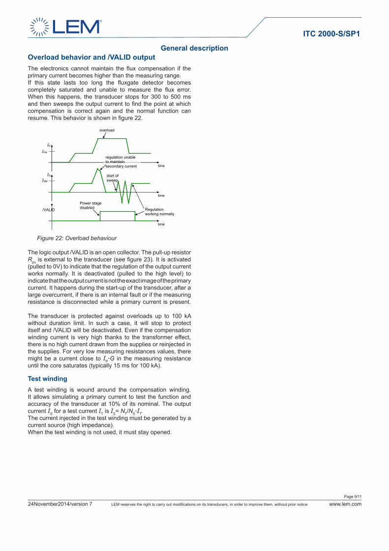
Overload behavior and /VALID outputThe electronics cannot maintain the flux compensation if the primary current becomes higher than the measuring range.If this state lasts too long the fluxgate detector becomes completely saturated and unable to measure the flux error. When this happens, the transducer stops for 300 to 500 ms and then sweeps the output current to find the point at which compensation is correct again and the normal function can resume. This behavior is shown in figure 22.
Figure 22: Overload behaviour
The logic output /VALID is an open collector. The pull-up resistor Rpu is external to the transducer (see figure 23). It is activated (pulled to 0V) to indicate that the regulation of the output current works normally. It is deactivated (pulled to the high level) to indicate that the output current is not the exact image of the primary current. It happens during the start-up of the transducer, after a large overcurrent, if there is an internal fault or if the measuring resistance is disconnected while a primary current is present. The transducer is protected against overloads up to 100 kA without duration limit. In such a case, it will stop to protect itself and /VALID will be deactivated. Even if the compensation winding current is very high thanks to the transformer effect, there is no high current drawn from the supplies or reinjected in the supplies. For very low measuring resistances values, there might be a current close to IP·G in the measuring resistance until the core saturates (typically 15 ms for 100 kA).
Test windingA test winding is wound around the compensation winding. It allows simulating a primary current to test the function and accuracy of the transducer at 10% of its nominal. The output current IS for a test current IT is IS= NT/NS·IT.The current injected in the test winding must be generated by a current source (high impedance).When the test winding is not used, it must stay opened.
regulation unable to maintain secondary current
time
/VALID
time
IP
time
IS
IPM
ISM
overload
start of sweep
Regulation working normally
Power stage disabled
General description

Page 10/11
24November2014/version 7 LEM reserves the right to carry out modifications on its transducers, in order to improve them, without prior notice www.lem.com
ITC 2000-S/SP1
The schematic used to measure all electrical parameters are:
UC
UC
IT
RM
ISIS
IP
Figure 23: Standard characterization schematics for current output transducers
Transducer simplified modelThe static model of the transducer at temperature TA is: IS = G·IP +error In which error = IOE+IOT (TA) +εG·G·IP +εGT (TA)·G·IP +εL·G·IPM +IOM IS : secondary current (A) G : sensitivity of the transducer (A/A) IP : primary current (A) IPM : primary current, measuring range (A) TA : ambient operating temperature (°C) IOE : electrical offset current (A) IOM : magnetic offset current (A) IOT (TA) : temperature variation of IO at temperature TA (A) εG : sensitivity error at 25 °C εGT (TA) : thermal drift of sensitivity at temperature TA εL : linearity error
This is the absolute maximum error. As all errors are independent, a more realistic way to calculate the error would be to use the following formula:
error =
Sensitivity and linearityTo measure sensitivity and linearity, the primary current (DC) is cycled from 0 to IPM, then to -IPM and back to 0 (equally spaced IPM/10 steps).The sensitivity G is defined as the slope of the linear regression line for a cycle between ±IPM.The linearity error εL is the maximum positive or negative difference between the measured points and the linear regression line, expressed in % of the maximum measured value.
Magnetic offsetThe magnetic offset IOM is the change of offset after a given current has been applied to the input. It is included in the linearity error as long as the transducer remains in its measuring range. Due to its working principle, this type of transducer has small magnetic offset current.
Electrical offsetThe electrical offset current IOE is the residual output current when the input current is zero (magnetic offset removed).The temperature variation IOT of the electrical offset current IOE is the variation of the electrical offset from 25 °C to the considered temperature.
Overall accuracyThe overall accuracy XG is the error at a given current (IPN if not mentioned), relative to the rated value IPN or to the reading.It includes all errors mentioned above.
Response and reaction timesThe response time tr and the reaction time tra are shown in the next figure.Both slightly depend on the primary current di/dt. They are measured at nominal current.
Figure 24: Response time tr and reaction time tra
Performance parameters definition
∑ 2)_( componenterror
tra
I
tr
90 %
10 %
t
100 %
I
I
Sp

Page 11/11
24November2014/version 7 LEM reserves the right to carry out modifications on its transducers, in order to improve them, without prior notice www.lem.com
ITC 2000-S/SP1
Mechanical characteristics General tolerance ±1 mm Measuring head
Transducer fastening 4 slots or holes 7 mm 4 M6 steel screws Recommended fastening torque 5 N·m (±10 %)
Electronic module Output connection D-Sub male connector 15 cts with M3 hexagonal locking screws Electronic module fastening 4 M5 screw Recommended fastening torque 5 N·m (±10 %)
Remarks IS is positive when IP flows in the direction of arrow. The secondary cables also have to be routed together all the
way. Installation of the transducer is to be done without primary or
secondary voltage present. Maximum temperature of primary conductor: see page 2 Installation of the transducer must be done unless otherwise
specified on the datasheet, according to LEM Transducer Generic Mounting Rules. Please refer to LEM document N°ANE120504 available on our Web site: Products/Product Documentation.
Dimensions (in mm)
Safety
This transducer must be used in electric/electronic equipment with respect to applicable standards and safety requirements in accordance with the manufacturer’s operating instructions.
Caution, risk of electrical shock
When operating the transducer, certain parts of the module can carry hazardous voltage (eg. primary busbar, power supply). Ignoring this warning can lead to injury and/or cause serious damage. This transducer is a build-in device, whose conducting parts must be inaccessible after installation. A protective housing or additional shield could be used. Main supply must be able to be disconnected.
Connection
UC
UC
IS
ISIP
IT
dCI dCp