curtainwall primer for design professionals - · pdf filecurtainwall primer for design...
TRANSCRIPT

PDHonline Course S119 (1 PDH)
Curtainwall Primer for Design Professionals
Instructor: D. Matthew Stuart, P.E., S.E., F.ASCE, F.SEI, SECB, MgtEng
2016
PDH Online | PDH Center
5272 Meadow Estates Drive
Fairfax, VA 22030-6658
Phone & Fax: 703-988-0088
www.PDHonline.org
www.PDHcenter.com
An Approved Continuing Education Provider
www.PDHonline.orgwww.PDHcenter.com
This presentation includes a discussion of curtainwalls used to enclosed buildings.
1© D. Matthew Stuart
www.PDHonline.orgwww.PDHcenter.com
The purpose of this course is to provide a basic understanding of the different types of curtainwall systems that are commercially available and commonly used in building construction. In addition, a basic understanding of curtainwall systems as they relate to the structural design and detailing of the supports required for this type of building cladding will also be discussed. A basic understanding of curtainwalls helps to assure that the structural engineer of record, the architect and the curtainwall vender all communicate clearly during the design and construction of a building.
In addition, I will also discuss non‐curtainwall systems in order to highlight the difference between curtainwall and non‐curtainwall systems, and to cover the more broad topic of building cladding as it relates to structural design.
A more detailed resource that is also available from ASCE includes the Curtainwall System Engineering Practice Manual No. 126 that is shown on this slide. This document provides more detailed information on curtainwall components, design, testing and construction.
2© D. Matthew Stuart

www.PDHonline.orgwww.PDHcenter.com
A curtainwall is an exterior, non‐load bearing cladding system which uses glass and vertical and horizontal mullions acting as structural members to transfer wind and gravity forces to the building structure. The glass can either be transparent or opaque, which is often referred to as spandrel glass. The spandrel portion can also be metal panel or some other similar opaque material. The entire system is typically supplied and installed by one contractor, and normally weighs approximately 8 to 10 PSF. The manufacturer’s in‐house engineering staff also typically provides the structural design and ensures the structural integrity of the curtainwall systemstructural integrity of the curtainwall system.
Curtainwalls first appeared in the early 1900’s and by the mid‐1930s new technologies had paved the way for developments in metal curtainwall panels. After World War II, metal and glass curtainwall systems started appearing on commercial and institutional buildings. Large areas of glass became possible in the 1950s with the invention of the float process glass manufacturingfloat process glass manufacturing.
The types of curtainwall systems in use today include Stick, Unitized, Column Cover & Spandrel, and Point‐Loaded Structural Glazing. These classifications are based on the type of frames used to construct the curtainwall and where the system is assembled.
3© D. Matthew Stuart

www.PDHonline.orgwww.PDHcenter.com
This slide illustrates an example of an opaque spandrel glass, which typically occurs at the floor and roof levels in order to hide and conceal the structure framing.
4© D. Matthew Stuart

www.PDHonline.orgwww.PDHcenter.com
Curtainwalls should not be confused with Window Wall systems. The main difference between these two systems is the relationship of the edge of the structure to the backup framing for the façade or building cladding. Window Walls are constructed between the framed floor structures while a curtainwall is located beyond the edge of the framed structure.
Highlight using screen cursor
5© D. Matthew Stuart

www.PDHonline.orgwww.PDHcenter.com
Both Curtainwall and Window Wall systems require a method of attachment to the main structure; however, Curtainwall systems normally also require a Firestop between the outside edge of the framed floor structure and the inside face of the Curtainwall.
Highlight using screen cursor
6© D. Matthew Stuart

www.PDHonline.orgwww.PDHcenter.com
Curtainwalls must perform as intended in order to provide a proper building enclosure envelope. Categories of performance include:
1. Water Penetration Resistance
2. Air Infiltration Resistance
3. Structurally adequate enough to transfer imposed loads back to the main structure.
4. Energy Efficiency
5. Aesthetics
6. Durability and Ease of Maintenance
7. …and Special Performance criteria including sound attenuation, fire resistance and blast resistanceblast resistance.
7© D. Matthew Stuart

www.PDHonline.orgwww.PDHcenter.com
A Stick curtainwall is a system in which the mullions are installed first, and then the glass panels are inserted into the mullion framing in the field. The vertical deflection criterion is more stringent for this type of system. The primary advantage of this system is it's lower cost.
8© D. Matthew Stuart

www.PDHonline.orgwww.PDHcenter.com
…and here is a photo of the installation of a Stick System curtainwall.
Highlight using screen cursor
9© D. Matthew Stuart

www.PDHonline.orgwww.PDHcenter.com
A Unitized curtainwall is a system in which the mullions are fabricated with the glass panels sometimes already in place, and then erected as individual panels. The primary disadvantage of this system is that it is more expensive than a stick system.
10© D. Matthew Stuart

www.PDHonline.orgwww.PDHcenter.com
…and here is a photo of the installation of a Unitized System curtainwall.
Highlight using screen cursor
11© D. Matthew Stuart

www.PDHonline.orgwww.PDHcenter.com
Advantages of the Unitized system include:
1. The curtainwall erection time is reduced.
2. Unitized panels can tolerate more vertical deflection in the structure due to the gasketed joints between each unit.
3. The gasketed joints also allow the curtainwall to form an incremental expansion joint at each mullion which in turn provides for almost unlimited adjustment.
12© D. Matthew Stuart
www.PDHonline.orgwww.PDHcenter.com
There are three basic types of Unitized System curtainwalls:
1.Screw‐Spline or Ladder.
2.Pre‐Glazed, and…
3.Unit or Panel. This system, which is the most recognized of the three types, includes fully assembled and glazed panel units.
13© D. Matthew Stuart
www.PDHonline.orgwww.PDHcenter.com
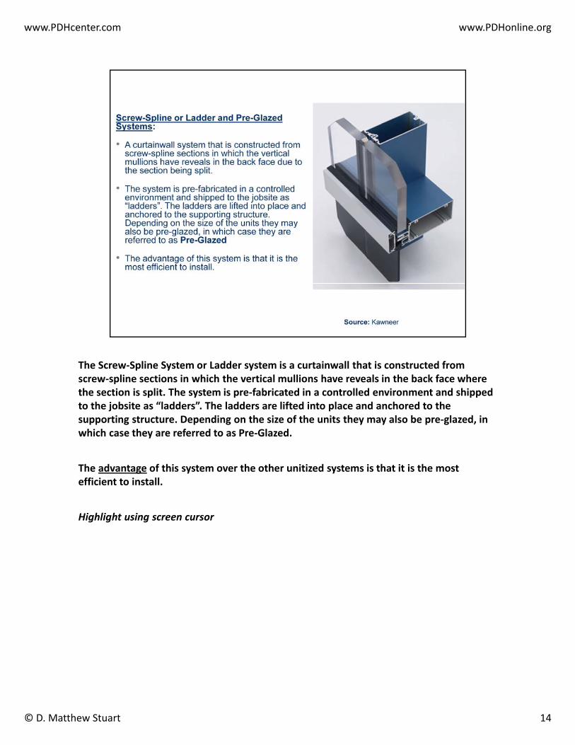
The Screw‐Spline System or Ladder system is a curtainwall that is constructed from screw‐spline sections in which the vertical mullions have reveals in the back face where the section is split. The system is pre‐fabricated in a controlled environment and shipped to the jobsite as “ladders”. The ladders are lifted into place and anchored to the supporting structure. Depending on the size of the units they may also be pre‐glazed, in which case they are referred to as Pre‐Glazed.
The advantage of this system over the other unitized systems is that it is the most efficient to install.
Highlight using screen cursor
14© D. Matthew Stuart
www.PDHonline.orgwww.PDHcenter.com
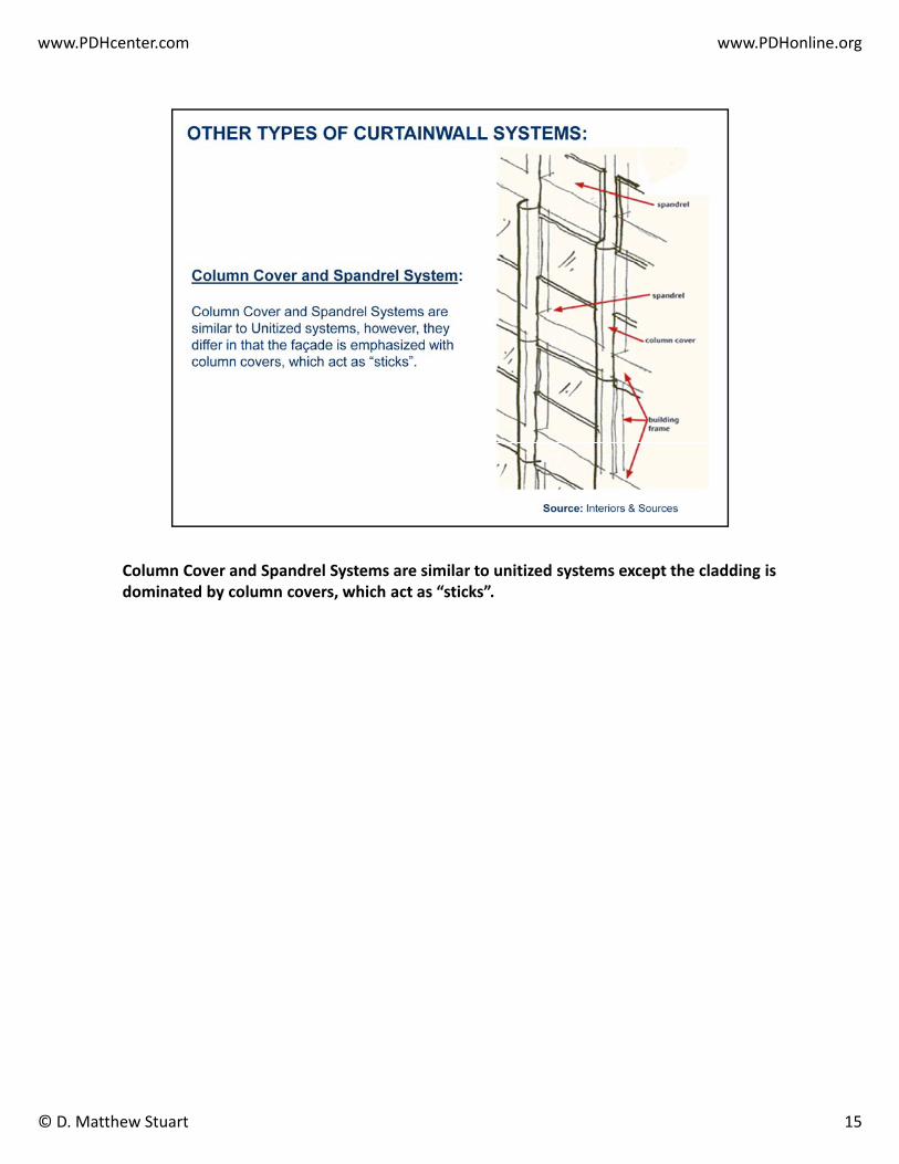
Column Cover and Spandrel Systems are similar to unitized systems except the cladding is dominated by column covers, which act as “sticks”.
15© D. Matthew Stuart

www.PDHonline.orgwww.PDHcenter.com
…and here is a photo of an example of a Column Cover and Spandrel System using prefabricated GFRC panels on light gage metal stud backup frames.
Highlight using screen cursor
16© D. Matthew Stuart

www.PDHonline.orgwww.PDHcenter.com
A Point Loaded Structural Glazing Systems is a type of curtainwall system in which the vertical framing member can include stick, cable, or another customized structural elements on the inside face of the glass. The glass is supported by a system of four‐point brackets, and the joints are sealed with silicone.
17© D. Matthew Stuart

www.PDHonline.orgwww.PDHcenter.com
Here are some examples of a Structural Glazing System. The primary wind resisting element that spans vertically between each level of the building is highlighted in each image.
18© D. Matthew Stuart

www.PDHonline.orgwww.PDHcenter.com
Similar to the different classifications of curtainwall types there are also different types of glass listed on this slide that can be used in a curtainwall.listed on this slide that can be used in a curtainwall.
1.Float glass was developed in the 1950’s by Pilkington and enabled the production of large sheets of glass.
2.Annealed glass undergoes a controlled heating and cooling process that improves its fracture resistance; however, the material can break into sharp pieces and as a result many building codes limit its use.
3.Tempered glass is chemically or thermally treated to provide improved strength and shatter resistance. When a sheet of tempered glass is broken it shatters into tiny pieces that are less likely to cause injury.
4.Heat and Chemically Strengthened glass is a material that falls between annealed and tempered glass in terms of strength, but similar to annealed glass is prone to break into sharp pieces. Scratches in the this type of glass can also compromise the strength of the material.
5.Laminated glass bonds two or more sheets of glass to an interlayer of plastic (typically PVB) which holds the glass in place if it becomes broken. This type of glass is often specified for curtainwalls in hurricane prone regions or building that must satisfy blast requirements.
6.Insulating glazing units, or IGUs, improve thermal performance through the use of double or triple panes of glass which are separated by a space filled with air or an inert gas.
7.…and finally Spandrel glass, which I mentioned earlier, is a darkened or opaque pane or panel that is used to hide the supporting structure or create other visual illusions in conjunction withthat is used to hide the supporting structure or create other visual illusions in conjunction with the adjacent curtainwall.
19© D. Matthew Stuart

www.PDHonline.orgwww.PDHcenter.com
In addition to the different types of frames and glass used in curtainwalls, additional classifications include:
1. Special functions include fire resistance, acoustical properties and blast resistance.
2. The most common type of mullion material is aluminum; however, wood, steel and composites are sometimes integrated into aluminum mullions and of course there iscomposites are sometimes integrated into aluminum mullions, and of course there is also glass mullions used in the point loaded glazing systems.
3. Types of mullion configurations include tubular, trussed, cable stayed and again glass for point loaded systems.
4. Methods of glass attachment include captured, structural and planar, with either internal or external replacement access.
20© D. Matthew Stuart

www.PDHonline.orgwww.PDHcenter.com
Let’s now talk about some general curtainwall recommendations.
• The design of the support members for a curtainwall should be based on component and cladding pressures obtained from the governing Building Code.
• The limiting vertical and horizontal defection criteria should be obtained from the manufacturer so that the connections between the curtainwall and adjacentmanufacturer so that the connections between the curtainwall and adjacent supporting structure can be detailed to prevent imposing any gravity loads, via the deflection of the building frame, on to the curtainwall system.
• The Contract Drawings should clearly indicate where the gravity load of the curtainwall is to be supported.
21© D. Matthew Stuart

www.PDHonline.orgwww.PDHcenter.com
• It is also recommended that for full height curtainwalls on a building of 5 to 6 stories, that the gravity load of the wall be supported at the lowest or foundation level with the connections at all of the upper framed levels providing lateral support only.
• On taller building and shorter building in which the curtainwall system starts at an upper floor, the gravity load support of the curtainwall should occur at regularly spaced intermediate floors or at the lowest level that the curtainwall begins.
22© D. Matthew Stuart

www.PDHonline.orgwww.PDHcenter.com
• In a tall building the joint between the bottom of the upper gravity supported curtainwall section and the top of the lower laterally connected wall should allow for the deflection of the framed support level so that no gravity loads will be imposed on the lower section.
• In addition, the joint should allow for any differential deflection between the lower and upper supported walls so that the horizontal expansion joint between the two different sections of walls can be properly maintained.
• Also, the manufacturer of the curtainwall system should account for any differential interstory building sway and thermal movement of the wall in the design of the system and the connections to the main building supports.
23© D. Matthew Stuart

www.PDHonline.orgwww.PDHcenter.com
Important curtainwall structural wind loading design considerations include the following items:
• The required site specific design loading for the curtainwall should be provided in the contract documents.
• This can be documented in the curtainwall specifications in the form of a narrative• This can be documented in the curtainwall specifications in the form of a narrative regarding loads and/or building elevations showing the required loading on the drawings.
• In all cases, this must be done using "components and cladding" loads from the building code.
24© D. Matthew Stuart

www.PDHonline.orgwww.PDHcenter.com
• The local governing building code must be reviewed for the required components and cladding loads.
• For example, Ohio specifies one wind speed for the entire state.
• Massachusetts however specifies individual wind speeds for each county or city and divides the state into three zonesdivides the state into three zones.
• In determining these wind loads, it is important to know what the tributary area of a particular mullion is because this factors into the wind pressure used.
• Normally, you would assume a single mullion span and spacing in order to determine Normally, you would assume a single mullion span and spacing in order to determinethe tributary area.
25© D. Matthew Stuart

www.PDHonline.orgwww.PDHcenter.com
Glazed curtainwalls are capable of performing well when exposed to low levels of wind loads and pressures associated with hurricanes and blasts. This is because curtainwalls are capable of large horizontal deflections without the glass breaking when compared to rigidly supported punched window systems.
Curtainwalls walls can be designed to meet Department of Defense (DoD) and General Service Administration (GSA) blast requirements and blast performance testing standards per ASTM F 1642 (Standard Test Method for Glazing and Glazing Systems Subject to Airblast Loading).
However, it is important to understand that a curtainwall designed for blast criteria does not automatically qualify for hurricane loading.
Based on the required structural loading, impact protection and cyclical nature of the exposure, the components of a curtainwall system can involve low, medium and high pressure resistant mullions (including mullion reinforcement), low, medium and high pressure resistant glazing, and both wet (in other words silicone) and dry ( in other words gasketed) glazing joints.
26© D. Matthew Stuart

www.PDHonline.orgwww.PDHcenter.com
Even though glass is one of the weakest components of a building’s cladding, there are ways to strengthen the material for hurricane and blast loads. Strengthening can include laminated glazing using PVB interlayers for lower ranges of blast loads or multi‐ply polycarbonate plies for extreme blast loads. Glass laminated with interlayers of PVB can break but still take the brunt of hurricane impacts and bomb blasts while still protecting the building occupants.
Thicker glass, such as SentryGlas, can also be used to improve the performance of the glazing to wind borne debris and is 100 times stiffer than PVB and more tear resistant.
Mullion widths can also be increased in order to increase the glass bite (or how deep the glazing is buried into the mullion pocket) to allow the curtainwall to withstand higher wind loads and impact forces. This approach to strengthening a curtainwall is often the best method of improving the load resisting characteristics and performance of the system at the least cost. The use of dry or gasketed joints as opposed to wet or silicone joints for this approach helps to further reduce costs.
Curtainwall systems can also be strengthened by including steel sections within the aluminum mullion extrusions.
27© D. Matthew Stuart

www.PDHonline.orgwww.PDHcenter.com
Full‐scale curtainwall mockups are required for hurricane impact loading tests. The mockup must pass impact testing per ASTM E 1886 and E 1996 followed by cyclical pressure testing. The test is intended to simulate debris impact and the pulsating wind pressure that occurs during a hurricane.
The simulation involves using an airplane engine and propeller to create high wind speedThe simulation involves using an airplane engine and propeller to create high wind speed loads on the mockup. During the test water is sprayed on the face of the curtainwall to determine if it leaks.
28© D. Matthew Stuart

www.PDHonline.orgwww.PDHcenter.com
Curtainwall fasteners must have the required hardness, yield strength and tensile capacity to withstand the loads imposed on the system without compromising the structural integrity and weather‐tightness of the wall. In addition, depending on what type of substrate that the system is attached to, for instance concrete masonry or steel, different types of connectors are required for each material.
A useful reference for specifying fasteners is the American Architectural Manufacturers Associate Technical Information Report/Design Guide for Metal Cladding Fasteners. The Design Guide provides metal curtainwall designers with the data necessary to select fasteners for curtain wall framing members and components, and for anchoring the curtain wall to the building structure.
29© D. Matthew Stuart

www.PDHonline.orgwww.PDHcenter.com
There are three primary methods of fastening a curtainwall system to the main structure, all of which are shown here. Cast‐in‐Place anchors and post‐installed anchors are used exclusively to attach to concrete structures, while Power Actuated Fasteners, or PAF’s, can be used with concrete or steel structures.
30© D. Matthew Stuart

www.PDHonline.orgwww.PDHcenter.com
And here are specific examples of each type of method of fastening that are available from Hilti, along with the major advantages and disadvantages to each type of fastener.
Briefly mention and point out each
31© D. Matthew Stuart

www.PDHonline.orgwww.PDHcenter.com
Anticipated building frame deflections (both vertical and horizontal) must be coordinated with the curtain wall supplier. This is typically provided in the curtain wall specifications. The limiting deflection of the mullions and glass themselves is typically based on industry standards. The typical limiting vertical deflection in the curtain wall industry is only 1/4".
32© D. Matthew Stuart

www.PDHonline.orgwww.PDHcenter.com
• It is important to provide details to allow the building structure to deflect vertically without imposing undue loading or movement to the curtain wall.
• It must be stated clearly on the contract drawings where the gravity loading is assumed to be supported and where the lateral support is assumed to be provided.
• Connections to the structure can be from the screed angle the concrete slab or a• Connections to the structure can be from the screed angle, the concrete slab, or a “free‐floating” beam.
Highlight using screen cursor
33© D. Matthew Stuart

www.PDHonline.orgwww.PDHcenter.com
• It is also important to note that the connections to the building structure must sometimes also be capable of supporting the cladding dead load.
• Torsion, which is induced by the eccentricity of the curtainwall to the supporting structure, should also be considered.
• Curtainwall connections should be reviewed thoroughly during the shop drawing• Curtainwall connections should be reviewed thoroughly during the shop drawing submittal process.
34© D. Matthew Stuart

www.PDHonline.orgwww.PDHcenter.com
Examples of various types of curtainwall connections designed and developed by the building structural engineer of record are provided on the following slides. This slide is an example of a clip angle supported by a composite concrete slab and metal deck edge.
Point out note concerning who is responsible of providing the lateral and gravity load curtainwall connections.
35© D. Matthew Stuart

www.PDHonline.orgwww.PDHcenter.com
Here is another composite concrete slab and metal deck edge support that involves an embedded bent plate.
36© D. Matthew Stuart

www.PDHonline.orgwww.PDHcenter.com
This composite concrete slab and metal deck edge support detail involves an external bent plate. Note that the vertically slotted holes at the mullion, which prevents the transmission of vertical loads between the curtainwall and the structure, have been provided at this level.
The length of the vertical slot is a function of:
1 The anticipated live load deflection of the supporting structure and1. The anticipated live load deflection of the supporting structure, and…
2. The anticipated thermal movement of the curtainwall.
Highlight using screen cursor
37© D. Matthew Stuart

www.PDHonline.orgwww.PDHcenter.com
This is an example of an embedded plate in the edge of a cast‐in‐place concrete slab edge.
For this example the curtainwall manufacturer is directed to support both gravity and lateral loads at each level.
Highlight using screen cursorHighlight using screen cursor
38© D. Matthew Stuart

www.PDHonline.orgwww.PDHcenter.com
Here is another slab edge connection example of a curtainwall system that also includes a metal stud backup wall, which was required for the support of the architectural interior finishes; however, the studs were also used to transfer the gravity and lateral load of the curtainwall to the supporting structure.
Highlight using screen cursor
39© D. Matthew Stuart

www.PDHonline.orgwww.PDHcenter.com
This slide illustrates curtainwall connections at a steel framed roof edge.
40© D. Matthew Stuart

www.PDHonline.orgwww.PDHcenter.com
Curtainwalls also sometimes require special supplemental, architecturally exposed backup structures to support the glazing system as illustrated in this slide. In this case horizontal trussed girts laterally brace the curtainwall. The trussed girts span between vertical trussed wind columns that span from the floor to the roof framing.
41© D. Matthew Stuart

www.PDHonline.orgwww.PDHcenter.com
As was mentioned at the start of this presentation, fire safety is another area of concern when detailing curtainwalls. The gap between the edge of a floor and the inside face of a curtainwall does little to impede fire and smoke, therefore fire stops and smoke seals should be located within this same gap. In addition, tempered knockout panels, designed to fracture and provide access during a fire, should be considered.
Highlight using screen cursor
42© D. Matthew Stuart

www.PDHonline.orgwww.PDHcenter.com
As mentioned earlier, a variety of additional factors can influence the performance of a curtainwall system.
• Air and water infiltration, the quality of materials and installation, and other similar issues have the potential to lead to curtainwall failure.
• To help maintain the life of a curtainwall system periodic checks of gaskets seals and• To help maintain the life of a curtainwall system, periodic checks of gaskets, seals and system joints should be conducted on a regular and routine basis.
• Perimeter sealants, which are typically capable of 10 to 15 year of service life should be carefully inspected and replaced as required on a similar schedule.
• It is also interesting to note that curtainwall systems typically cost more than standard window systems.
43© D. Matthew Stuart

www.PDHonline.orgwww.PDHcenter.com
Common sources of curtainwall failures are listed on this slide and include:
1. Excessive deflection of the mullions when exposed to out of plane forces can contribute to the failure of a curtainwall by causing leaks at the joints and damage to the glazing. Deflection of mullions is controlled through proper sizing of the aluminum crosssection and in some cases via internal reinforcing using structural steel shapes. Proper sizing of the mullions is the responsibility of the delegated curtainwall designer; however, the building structural engineer of record should confirm the correct lateralloads have been used by the curtainwall designer.
2. Lack of coordination between the building structural engineer of record and the delegated curtainwall designer can result in failures caused by unanticipated excessive vertical deflection of the supporting floor or excessive differential horizontal swaybetween adjacent framed floors. To avoid this type of failure it is recommended that the building structural engineer of recorddocument the anticipated live load deflections and interstory differential horizontal sway at the areas of the structure used tosupport the curtainwall.pp
3. Failures associated with improper shop fabrication and field installation are best avoided by implementing a QA/QC program at the fabrication facility and the job site.
4. The most common source of poor maintenance is an underfunded budget established by the building or property manager over the life of the facility. In addition the omission of a commissioning phase or maintenance instruction manual at the end of the construction can also contribute to this type of curtainwall failure.
5. Failures of the glazing system can include condensation due to failure of a hermetic seal in a IGU system, or excessively high relative humidity inside the building. Cracks in the glass due to excessive thermal stresses as a result of improper heat y g g p pstrengthening during manufacturing can also cause failures.
6. The incorrect installation of sealants typically occurs at frame corners and other similar intersections. In addition the use of a sealant that is not compatible with the curtainwall system or is not durable enough to provide a sufficient service life can also a source of a failure.
7. Another common cause of curtainwall problems is the failure of the gaskets and seals that secure the glazing. Gaskets are strips of synthetic rubber or plastic compressed between the gazing and the frame to form a watertight seal. As the gaskets age they begin to dry out, shrink and crack. As a result gaskets have to be maintained and replaced in order for the curtainwall to continue to operate properly. In lieu of gaskets some curtainwall systems use structural sealants, which are typically high‐strength silicone, to secure the glass to the frame. However, similar to gaskets structural sealants have a finite service life andstrength silicone, to secure the glass to the frame. However, similar to gaskets structural sealants have a finite service life and have to likewise be maintained and replaced.
44© D. Matthew Stuart

www.PDHonline.orgwww.PDHcenter.com
In order to better understand what a Curtainwall system is, it is helpful to also have an understanding of other non‐curtain wall systems such as Strip Windows and Punched Windows. Strip windows are sometimes referred to as Ribbon windows and involve a continuous uninterrupted band of window units. Punched windows, as the name implies, involves individual window openings that are separate from adjacent window openings.
Highlight using screen cursor
45© D. Matthew Stuart

www.PDHonline.orgwww.PDHcenter.com
Other types of non‐curtainwall claddings that may or may not involve window openings that structural engineers are involved with include the design of precast concrete and insulated metal wall panels.
46© D. Matthew Stuart
www.PDHonline.orgwww.PDHcenter.com
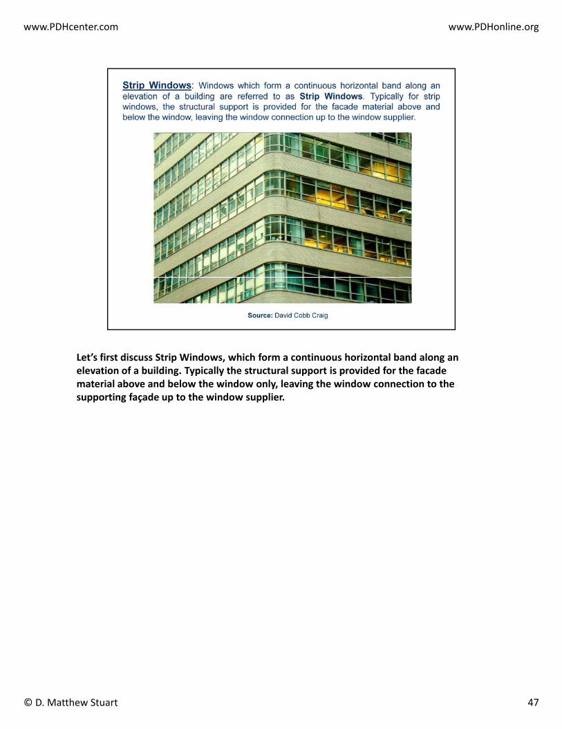
Let’s first discuss Strip Windows, which form a continuous horizontal band along an elevation of a building. Typically the structural support is provided for the facade material above and below the window only, leaving the window connection to the supporting façade up to the window supplier.
47© D. Matthew Stuart

www.PDHonline.orgwww.PDHcenter.com
Strip windows typically involve the use of continuous “hung” lintels that are used to support the cladding above the window opening. The “hung” lintels in turn are supported by and suspended from the floor or roof framing above the window head as illustrated in this slide.
Highlight using screen cursor
48© D. Matthew Stuart

www.PDHonline.orgwww.PDHcenter.com
Here are some additional examples of “hung” lintel details used at a Strip Window condition.
Highlight using screen cursor
49© D. Matthew Stuart

www.PDHonline.orgwww.PDHcenter.com
…and here are some additional roof edge “hung” lintel details.
Highlight using screen cursor
50© D. Matthew Stuart

www.PDHonline.orgwww.PDHcenter.com
Another type of special “hung” lintel is shown on this slide. This detail shows a proprietary system that is constructed integrally with masonry brick and is often used with suspended fake brick arches. This type of concealed system is manufactured by Halfen. Information concerning this system can be found at the company’s website: www.halfenusa.com
Highlight using screen cursor
51© D. Matthew Stuart

www.PDHonline.orgwww.PDHcenter.com
Punched Windows are individual windows which are "punched" into a building elevation. The facade or cladding surrounds the windows on all four sides of the opening. The structural support is typically provided for the entire facade system while the window supplier is responsible for the support of the window to the cladding at the sill, jambs, and head of the opening. The structural support framing can either be designed and detailed by the building engineer of record, or a performance specification can be provided for a delegated design by others. In the latter case the structural calculations details and shop drawings are submitted by an independent vendor andcalculations, details and shop drawings are submitted by an independent vendor and reviewed and approved by the project engineer of record.
52© D. Matthew Stuart

www.PDHonline.orgwww.PDHcenter.com
This slide illustrates the backup framing around punched window openings in a metal stud wall. Note that the jamb members have a considerable tributary area of wind loading, and that the same members must also resist the gravity load reactions of the lintels. The lintel support of a typical brick veneer that would clad a metal stud wall would be separate from the backup framing lintel and would bear on the brick jambs.
53© D. Matthew Stuart

www.PDHonline.orgwww.PDHcenter.com
Punched window openings in a CMU backup wall are constructed in a similar manner with reinforced jambs and lintels.
Highlight using screen cursor
54© D. Matthew Stuart

www.PDHonline.orgwww.PDHcenter.com
Punched window openings of many different configurations can be obtained with reinforced precast concrete panels.
55© D. Matthew Stuart

www.PDHonline.orgwww.PDHcenter.com
Here is a typical precast spandrel connection to a supporting building column in which the panel is capable of spanning between each column to support its self‐weight, and the weight of the window wall above.
Highlight using screen cursor
56© D. Matthew Stuart

www.PDHonline.orgwww.PDHcenter.com
And here is a plan detail at a vertical column cover precast panel supported directly from a building column.
Highlight using screen cursor
57© D. Matthew Stuart

www.PDHonline.orgwww.PDHcenter.com
Metal panel cladding is often used at mechanical penthouses and other similar industrial structures. This slide illustrates a metal panel clad penthouse along with the corresponding partial elevation of the supporting girts and columns. Note that HSS sections were used at the open cooling tower bay where the steel is exposed to exterior conditions, while wide flange section girts were used for interior exposures. Since wide flange girts are typically turned so the strong axis of the section is perpendicular to the ground, to maximize their resistance to wind loading, it is not recommended to use these same sections for exterior conditions because water can collect on top of the websame sections for exterior conditions because water can collect on top of the web between the upturned flanges, and cause corrosion of the steel.
58© D. Matthew Stuart

www.PDHonline.orgwww.PDHcenter.com
This slides provides the sections cut on the previous wall elevation. Note that sag rods are used to help the wide flange girt resist it’s own dead load, while this was not necessary with the HSS girt. For this particular project you will also note that vertically spanning light gage metal studs were used between the main support framing and the metal wall panels for supplemental interior architectural finishes that were required to hide the inside face of the exterior metal wall panels.
59© D. Matthew Stuart

www.PDHonline.orgwww.PDHcenter.com
Although there are exceptions with heavier cladding, for the most part girts (and wind columns) are typically only designed to resist wind loads on the building exterior, which typically controls over lateral seismic forces. In my opinion, the magnitude of wind load (both pressure and suction) imposed on a girt should always be based on the worse case component and cladding criteria, even if the total tributary area of the girt allows for a decrease in the design pressures.
Although just about any steel cross section can function as a girt, as indicated previously, it is typical for a wide flange to be laid on its side to allow the strong axis of the section to resist the horizontal forces. Channel sections are also sometimes laid on their side and used as girts. In either case, this situation results in a condition in which the weak axis of the member must resist all imposed dead loads, which typically includes just the self weight of the member and not the cladding. To overcome this condition, sag rods are used to support the girt at intermediate points across the horizontal span of the member.
Although the sag rods do not participate directly in the resistance to the imposed lateral wind loads they do serve the additional function of laterally bracing the compression flange of the member when the supporting wall is exposed to suction or negative wind y g p g pp g p gforces. When the wall is exposed to positive wind pressures, the compression flange of the beam is typically braced by the attachments to the cladding. An example of an Allowable Stress Design analysis of the bracing capabilities of sag rods of a girt is provided in this slide. The magnitude of bracing force imposed on the sag rod (i.e. 1% of the flange compression force) was established by Dr. Yura at the University of Texas, Austin.
It should also be noted that it is necessary to double nut the sag rod to the girt web to assure that the rod can resist buckling of the beam in either direction (i.e. up or down). In addition, mobilization of the dead load of the beam (typically only one half of the uniform dead weight of beam is assumed to account for any support provided by the connections to the cladding) also assists to prevent any buckling of the beam in the upward direction. When multiple layers of girts are employed due to the height of the wall it is necessary to articulate the sag rods (as opposed to running the rods continuously through the upper girts down to the lower girts) to assure that both the upper and lower girts are properly braced by the rods, and to aid with the constructability of the vertically stacked girts.
As previously illustrated HSS sections are also used as girts. In this situation, in which the member is typically symmetrical about both axis, the girt is designed to span the entire distance between the end supports for both lateral and gravity loads. For this scenario the girt must be checked for combined bi‐axial bending. Biaxial bending stresses must also be checked for a sag rod supported wide flange or channel girt, however, because of the relatively insignificant minor axis bending moments, this is typically not a controlling factor. For a PEMB it is typical to use cold formed metal sections such as a Z‐purlin laid on its side, and supported by sag rods, as a girt.
With the exception of masonry cladding (both brick and CMU), which is governed by ACI 530, the limiting deflection for any exterior cladding should be provided and established by the manufacturer of the system. This information is then used to establish theminimum section properties of the supporting girt and or wind column as it is not unusual for serviceability criteria to control over strength criteria when designing backup supports for building claddings.
60© D. Matthew Stuart

www.PDHonline.orgwww.PDHcenter.com
Finally, a good source of information concerning the design of façade attachments to steel framed building is Design Guide 22 published by the AISC. PCI is also an excellent resource for precast concrete panel and connection design.
61© D. Matthew Stuart