curve sign for - co.douglas.or.us · existing signs. w1-2. mile post. w1-1. w1-4. w1-3 w1. w1-5-8...
TRANSCRIPT
RECOMMENDED SIGNS
REQUIRED SIGNS
EXISTING SIGNS
MILE POST W1‐2
W1‐1
W1‐4
W1‐3
W1‐5
W1‐8
W13‐1P
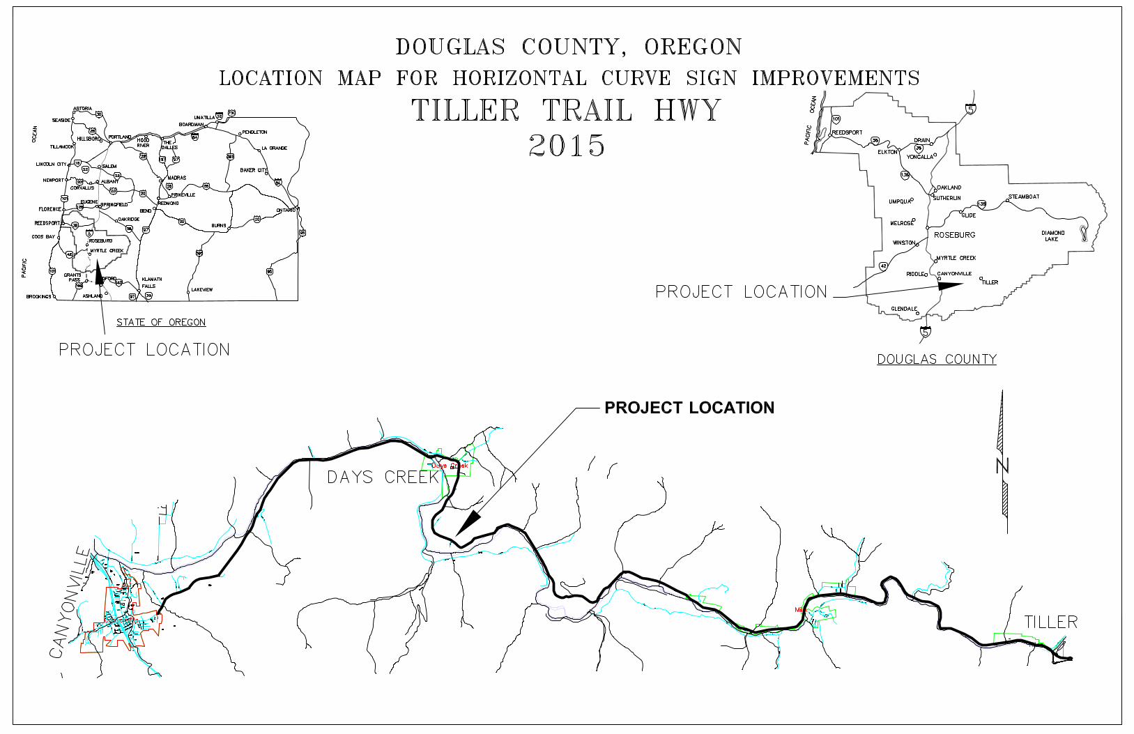
CURVE SIGN CHANGES FOR:
NORTH BANK RD (200)
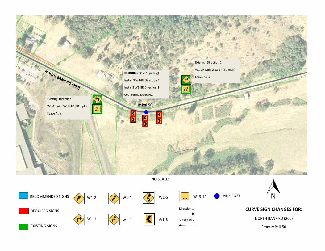
From MP: 0.50
NO SCALE:
Direc on 1
Direc on 2
30
30
MP:0.50
REQUIRED: (120’ Spacing)
Install 3 W1‐8L Direc on 1
Install3 W1‐8R Direc on 2
Countermeasure: RD7
NORTH BANK RD (200)
Exis ng: Direc on 2
W1‐1R with W13‐1P (30 mph)
Leave As Is
Exis ng: Direc on 1
W1‐1L with W13‐1P (30 mph)
Leave As Is
RECOMMENDED SIGNS
REQUIRED SIGNS
EXISTING SIGNS
MILE POST W1‐2
W1‐1
W1‐4
W1‐3
W1‐5
W1‐8
W13‐1P
CURVE SIGN CHANGES FOR:
NORTH BANK RD (200)
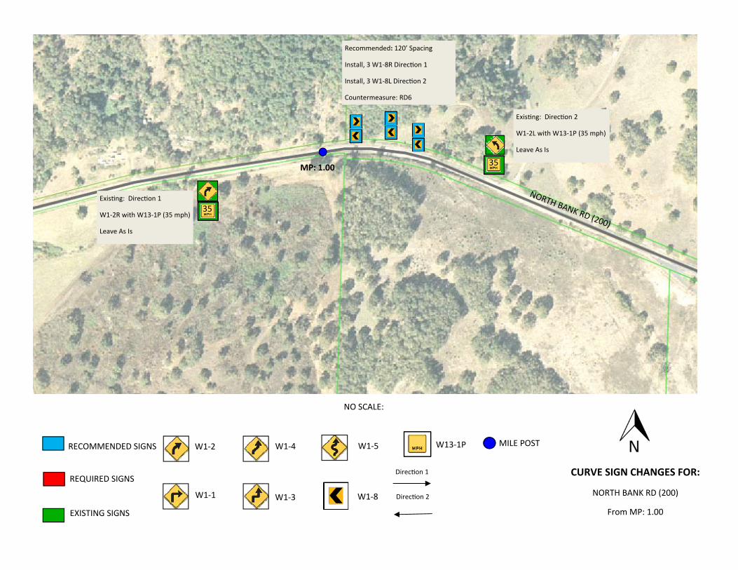
From MP: 1.00
NO SCALE:
Direc on 1
Direc on 2
MP: 1.00
35
35
Recommended: 120’ Spacing
Install, 3 W1‐8R Direc on 1
Install, 3 W1‐8L Direc on 2
Countermeasure: RD6
Exis ng: Direc on 1
W1‐2R with W13‐1P (35 mph)
Leave As Is
Exis ng: Direc on 2
W1‐2L with W13‐1P (35 mph)
Leave As Is
NORTH BANK RD (200)
RECOMMENDED SIGNS
REQUIRED SIGNS
EXISTING SIGNS
MILE POST W1‐2
W1‐1
W1‐4
W1‐3
W1‐5
W1‐8
W13‐1P
CURVE SIGN CHANGES FOR:
NORTH BANK RD (200)
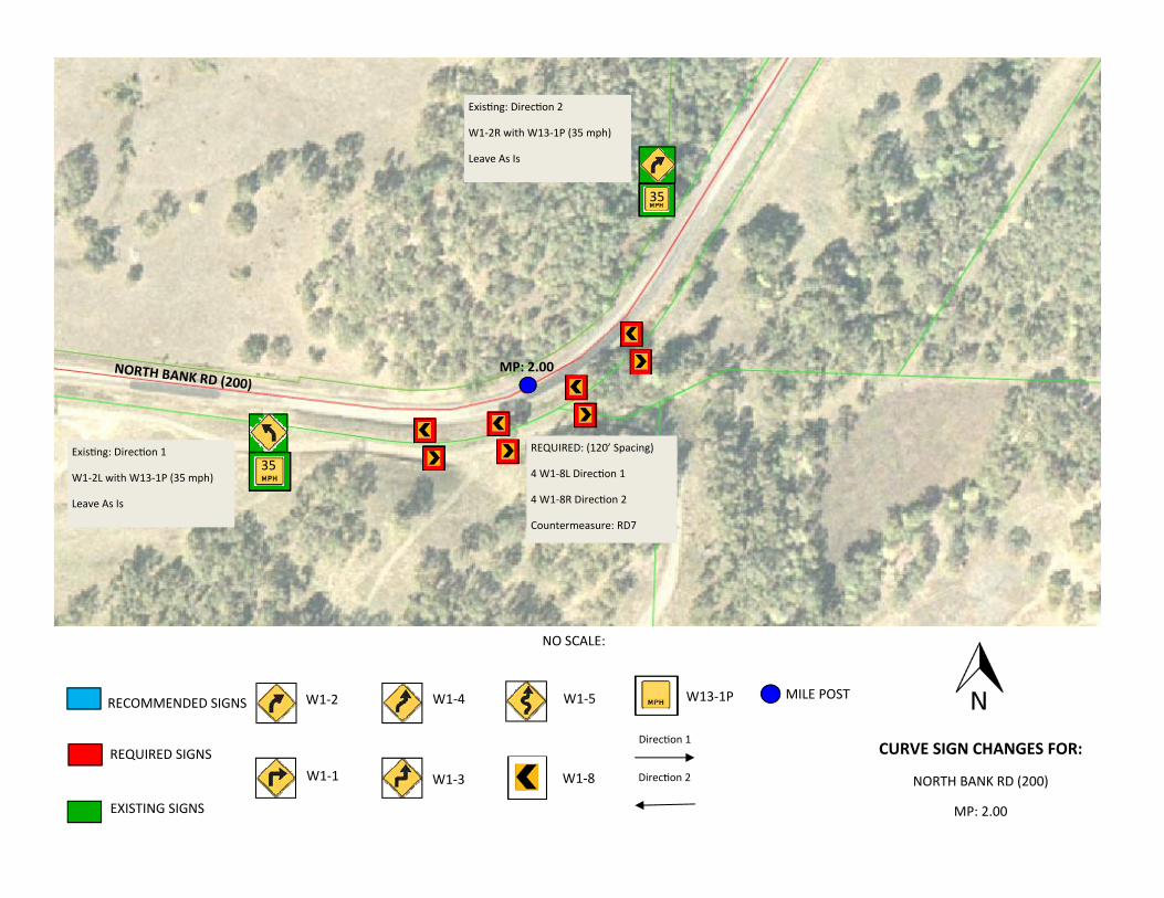
MP: 2.00
NO SCALE:
Direc on 1
Direc on 2
35
35
Exis ng: Direc on 2
W1‐2R with W13‐1P (35 mph)
Leave As Is
Exis ng: Direc on 1
W1‐2L with W13‐1P (35 mph)
Leave As Is
REQUIRED: (120’ Spacing)
4 W1‐8L Direc on 1
4 W1‐8R Direc on 2
Countermeasure: RD7
MP: 2.00 NORTH BANK RD (200)
RECOMMENDED SIGNS
REQUIRED SIGNS
EXISTING SIGNS
MILE POST W1‐2
W1‐1
W1‐4
W1‐3
W1‐5
W1‐8
W13‐1P
CURVE SIGN CHANGES FOR:
NORTH BANK RD (200)
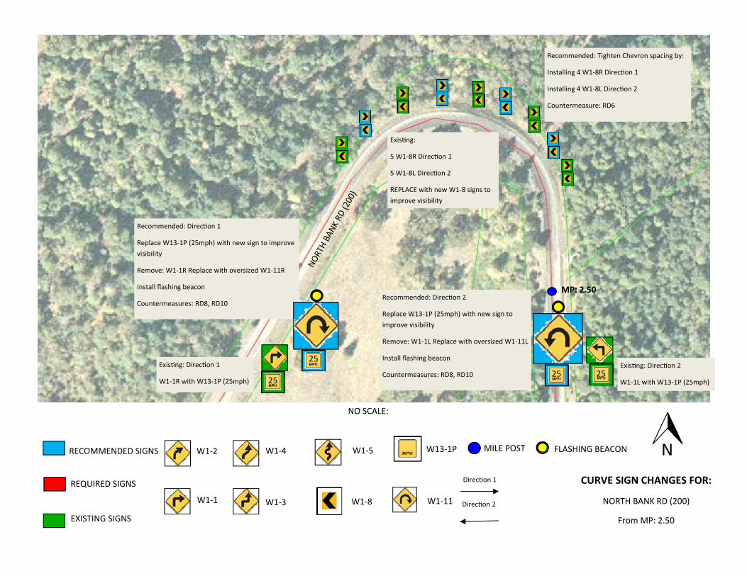
From MP: 2.50
NO SCALE:
Direc on 1
Direc on 2
25
NORTH BANK
RD (200)
MP: 2.50
Exis ng: Direc on 1
W1‐1R with W13‐1P (25mph)
Exis ng: Direc on 2
W1‐1L with W13‐1P (25mph) 25
Exis ng:
5 W1‐8R Direc on 1
5 W1‐8L Direc on 2
REPLACE with new W1‐8 signs to improve visibility
Recommended: Tighten Chevron spacing by:
Installing 4 W1‐8R Direc on 1
Installing 4 W1‐8L Direc on 2
Countermeasure: RD6
W1‐11
Recommended: Direc on 1
Replace W13‐1P (25mph) with new sign to improve visibility
Remove: W1‐1R Replace with oversized W1‐11R
Install flashing beacon
Countermeasures: RD8, RD10
25
FLASHING BEACON
Recommended: Direc on 2
Replace W13‐1P (25mph) with new sign to improve visibility
Remove: W1‐1L Replace with oversized W1‐11L
Install flashing beacon
Countermeasures: RD8, RD10 25
RECOMMENDED SIGNS
REQUIRED SIGNS
EXISTING SIGNS
MILE POST W1‐2
W1‐1
W1‐4
W1‐3
W1‐5
W1‐8
W13‐1P
CURVE SIGN CHANGES FOR:
NORTH BANK RD (200)
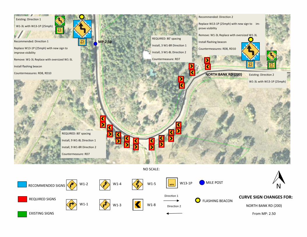
From MP: 2.50
NO SCALE:
Direc on 1
Direc on 2
Exis ng: Direc on 1
W1‐3L with W13‐1P (25mph)
25
25
Exis ng: Direc on 2
W1‐3L with W13‐1P (25mph)
REQUIRED: 80’ spacing
Install, 3 W1‐8R Direc on 1
Install, 3 W1‐8L Direc on 2
Countermeasure: RD7
REQUIRED: 80’ spacing
Install, 9 W1‐8L Direc on 1
Install, 9 W1‐8R Direc on 2
Countermeasure: RD7
MP:2.50
NORTH BANK RD (200)
Recommended: Direc on 1
Replace W13‐1P (25mph) with new sign to improve visibility
Remove: W1‐3L Replace with oversized W1‐3L
Install flashing beacon
Countermeasures: RD8, RD10
25
Recommended: Direc on 2
Replace W13‐1P (25mph) with new sign to im‐prove visibility
Remove: W1‐3L Replace with oversized W1‐3L
Install flashing beacon
Countermeasures: RD8, RD10
25
FLASHING BEACON
RECOMMENDED SIGNS
REQUIRED SIGNS
EXISTING SIGNS
MILE POST W1‐2
W1‐1
W1‐4
W1‐3
W1‐5
W1‐8
W13‐1P
CURVE SIGN CHANGES FOR:
NORTH BANK RD (200)
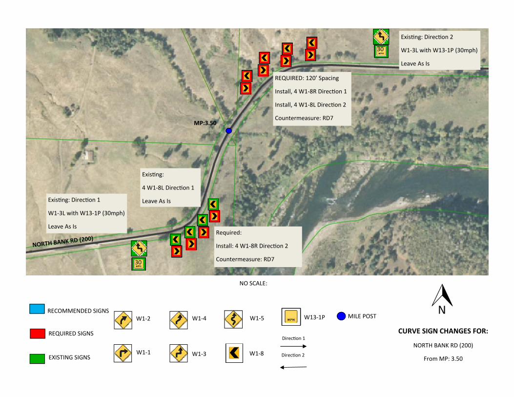
From MP: 3.50
NO SCALE:
Direc on 1
Direc on 2
30
30
Exis ng: Direc on 1
W1‐3L with W13‐1P (30mph)
Leave As Is
Exis ng: Direc on 2
W1‐3L with W13‐1P (30mph)
Leave As Is
Exis ng:
4 W1‐8L Direc on 1
Leave As Is
REQUIRED: 120’ Spacing
Install, 4 W1‐8R Direc on 1
Install, 4 W1‐8L Direc on 2
Countermeasure: RD7
NORTH BANK RD (200)
MP:3.50
Required:
Install: 4 W1‐8R Direc on 2
Countermeasure: RD7
RECOMMENDED SIGNS
REQUIRED SIGNS
EXISTING SIGNS
MILE POST W1‐2
W1‐1
W1‐4
W1‐3
W1‐5
W1‐8
W13‐1P
CURVE SIGN CHANGES FOR:
NORTH BANK RD (200)
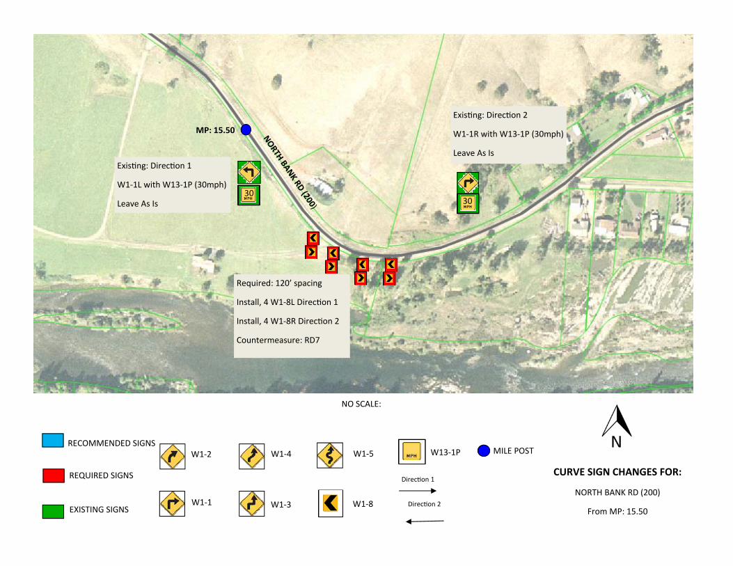
From MP: 15.50
NO SCALE:
Direc on 1
Direc on 2
MP: 15.50
30 30
Exis ng: Direc on 1
W1‐1L with W13‐1P (30mph)
Leave As Is
Exis ng: Direc on 2
W1‐1R with W13‐1P (30mph)
Leave As Is
Required: 120’ spacing
Install, 4 W1‐8L Direc on 1
Install, 4 W1‐8R Direc on 2
Countermeasure: RD7
NORTH BANK RD (200)
RECOMMENDED SIGNS
REQUIRED SIGNS
EXISTING SIGNS
MILE POST W1‐2
W1‐1
W1‐4
W1‐3
W1‐5
W1‐8
W13‐1P
CURVE SIGN CHANGES FOR:
NORTH BANK RD (200)
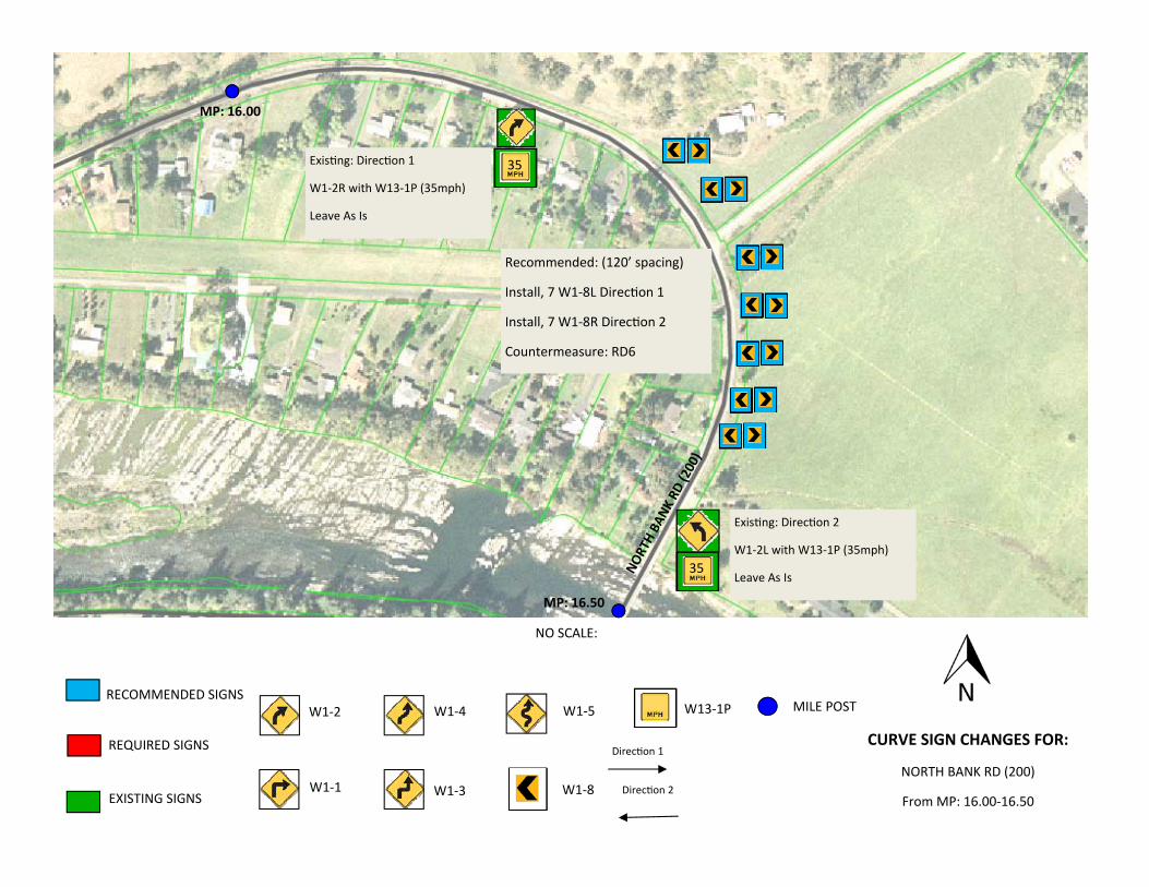
From MP: 16.00‐16.50
NO SCALE:
Direc on 1
Direc on 2
MP: 16.00
MP: 16.50
35
35
Exis ng: Direc on 1
W1‐2R with W13‐1P (35mph)
Leave As Is
Exis ng: Direc on 2
W1‐2L with W13‐1P (35mph)
Leave As Is
Recommended: (120’ spacing)
Install, 7 W1‐8L Direc on 1
Install, 7 W1‐8R Direc on 2
Countermeasure: RD6
NORTH BANK
RD (200)
RECOMMENDED SIGNS
REQUIRED SIGNS
EXISTING SIGNS
MILE POST W1-2
W1-1
W1-4
W1-3
W1-5
W1-8
W13-1P
CURVE SIGN CHANGES FOR:
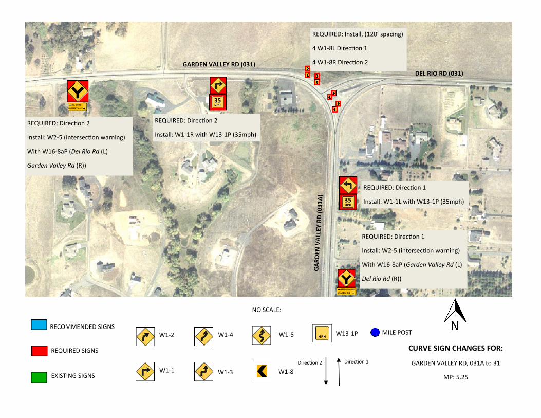
GARDEN VALLEY RD, 031A to 31
MP: 5.25
NO SCALE:
Direction 2 Direction 1
GARDEN VALLEY
DEL RIO RD
DEL RIO RD
GARDEN VALLEY
35
35
DEL RIO RD (031)
GARDEN VALLEY RD (031)
GA
RD
EN V
ALL
EY R
D (
03
1A
)
REQUIRED: Direction 2
Install: W2-5 (intersection warning)
With W16-8aP (Del Rio Rd (L)
Garden Valley Rd (R))
REQUIRED: Direction 2
Install: W1-1R with W13-1P (35mph)
REQUIRED: Direction 1
Install: W1-1L with W13-1P (35mph)
REQUIRED: Direction 1
Install: W2-5 (intersection warning)
With W16-8aP (Garden Valley Rd (L)
Del Rio Rd (R))
REQUIRED: Install, (120’ spacing)
4 W1-8L Direction 1
4 W1-8R Direction 2
RECOMMENDED SIGNS
REQUIRED SIGNS
EXISTING SIGNS
MILE POST W1‐2
W1‐1
W1‐4
W1‐3
W1‐5
W1‐8
W13‐1P
CURVE SIGN CHANGES FOR:
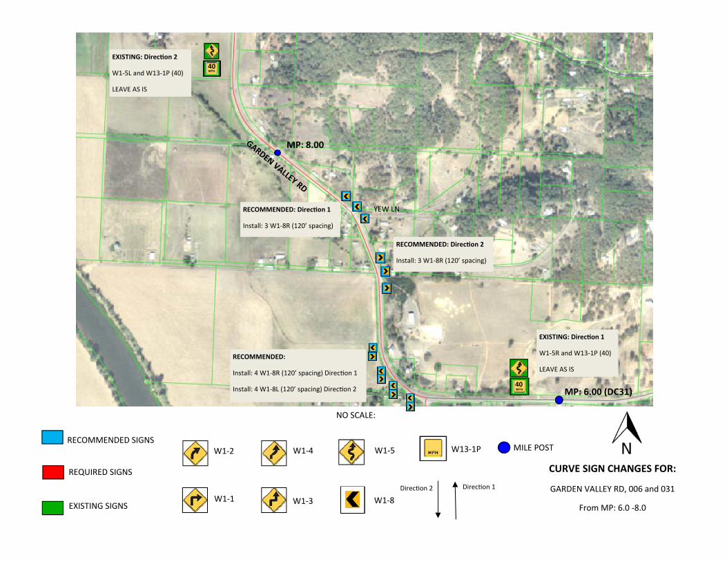
GARDEN VALLEY RD, 006 and 031
From MP: 6.0 ‐8.0
NO SCALE:
Direc on 2 Direc on 1
MP: 6.00 (DC31)
MP: 8.00
40
40
EXISTING: Direc on 1
W1‐5R and W13‐1P (40)
LEAVE AS IS
EXISTING: Direc on 2
W1‐5L and W13‐1P (40)
LEAVE AS IS
GARDEN VALLEY RD
RECOMMENDED: Direc on 2
Install: 3 W1‐8R (120’ spacing)
YEW LN RECOMMENDED: Direc on 1
Install: 3 W1‐8R (120’ spacing)
RECOMMENDED:
Install: 4 W1‐8R (120’ spacing) Direc on 1
Install: 4 W1‐8L (120’ spacing) Direc on 2
RECOMMENDED SIGNS
REQUIRED SIGNS
EXISTING SIGNS
MILE POST W1‐2
W1‐1
W1‐4
W1‐3
W1‐5
W1‐8
W13‐1P
CURVE SIGN CHANGES FOR:
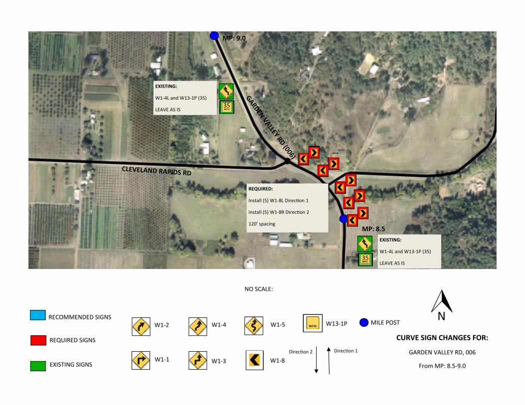
GARDEN VALLEY RD, 006
From MP: 8.5‐9.0
NO SCALE:
Direc on 2 Direc on 1
MP: 8.5
MP: 9.0
35
35
GARDEN VALLEY RD (006)
CLEVELAND RAPIDS RD
REQUIRED:
Install (5) W1‐8L Direc on 1
Install (5) W1‐8R Direc on 2
120’ spacing
EXISTING:
W1‐4L and W13‐1P (35)
LEAVE AS IS
EXISTING:
W1‐4L and W13‐1P (35)
LEAVE AS IS
RECOMMENDED SIGNS
REQUIRED SIGNS
EXISTING SIGNS
MILE POST W1‐2
W1‐1
W1‐4
W1‐3
W1‐5
W1‐8
W13‐1P
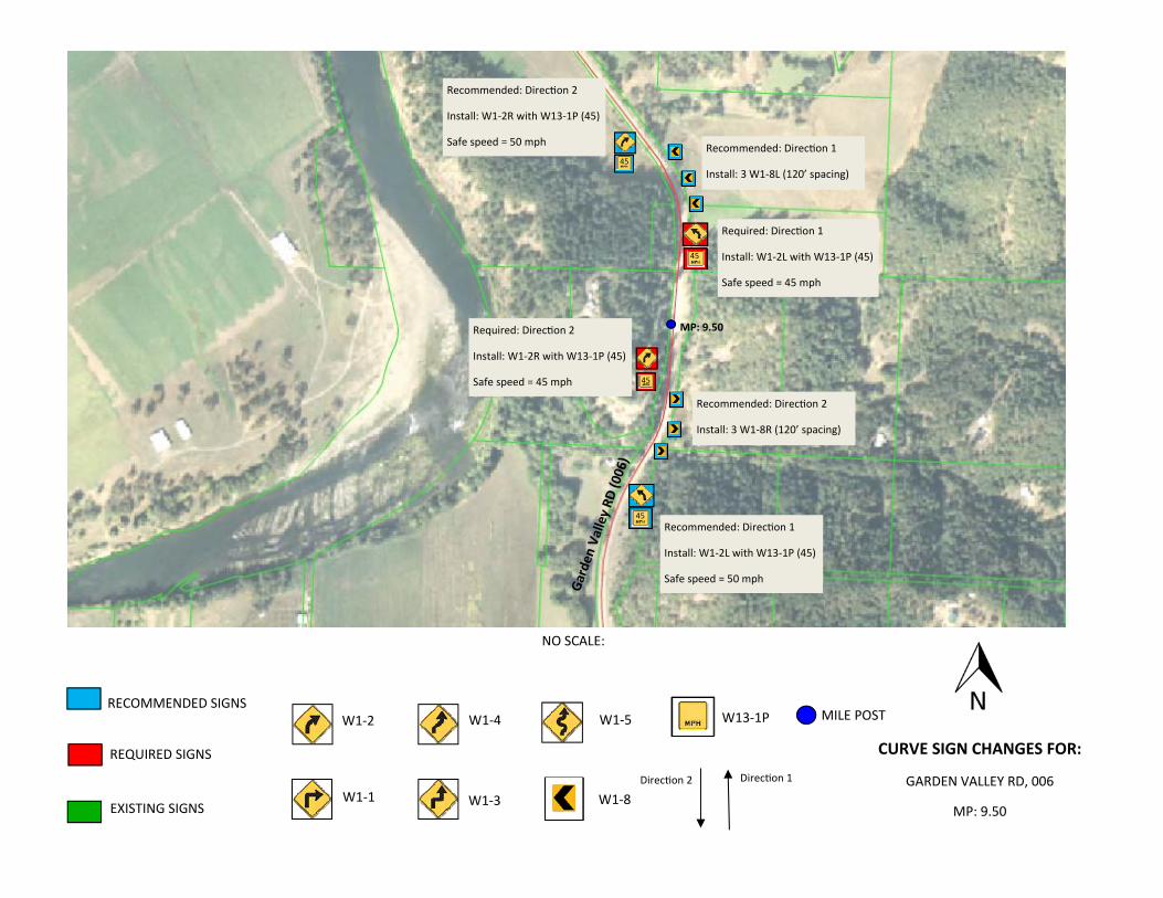
CURVE SIGN CHANGES FOR:
GARDEN VALLEY RD, 006
MP: 9.50
NO SCALE:
Direc on 2 Direc on 1
45
45
45
45
Required: Direc on 1
Install: W1‐2L with W13‐1P (45)
Safe speed = 45 mph
Required: Direc on 2
Install: W1‐2R with W13‐1P (45)
Safe speed = 45 mph
Recommended: Direc on 2
Install: W1‐2R with W13‐1P (45)
Safe speed = 50 mph
Recommended: Direc on 1
Install: W1‐2L with W13‐1P (45)
Safe speed = 50 mph
Recommended: Direc on 2
Install: 3 W1‐8R (120’ spacing)
Recommended: Direc on 1
Install: 3 W1‐8L (120’ spacing)
MP: 9.50
Garden
Valley RD
(006)
RECOMMENDED SIGNS
REQUIRED SIGNS
EXISTING SIGNS
MILE POST W1‐2
W1‐1
W1‐4
W1‐3
W1‐5
W1‐8
W13‐1P
CURVE SIGN CHANGES FOR:
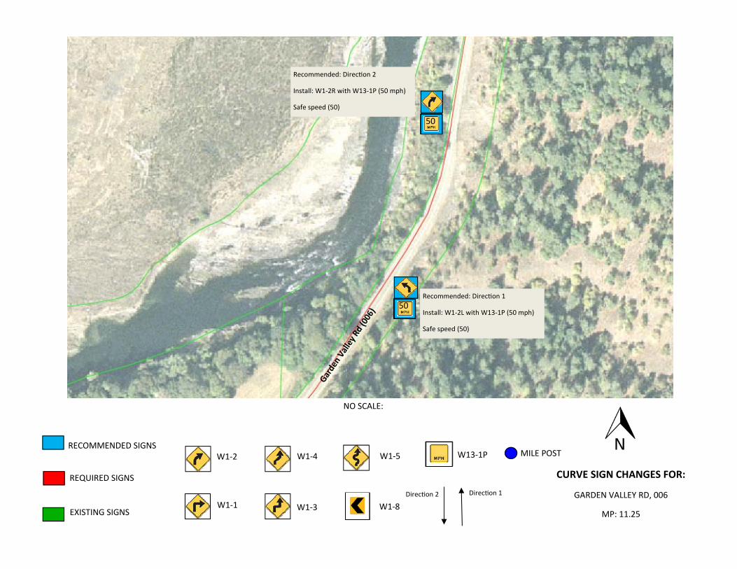
GARDEN VALLEY RD, 006
MP: 11.25
NO SCALE:
Direc on 2 Direc on 1
50
50
Recommended: Direc on 1
Install: W1‐2L with W13‐1P (50 mph)
Safe speed (50)
Recommended: Direc on 2
Install: W1‐2R with W13‐1P (50 mph)
Safe speed (50)
Garden Valley Rd (006)
RECOMMENDED SIGNS
REQUIRED SIGNS
EXISTING SIGNS
MILE POST W1‐2
W1‐1
W1‐4
W1‐3
W1‐5
W1‐8
W13‐1P
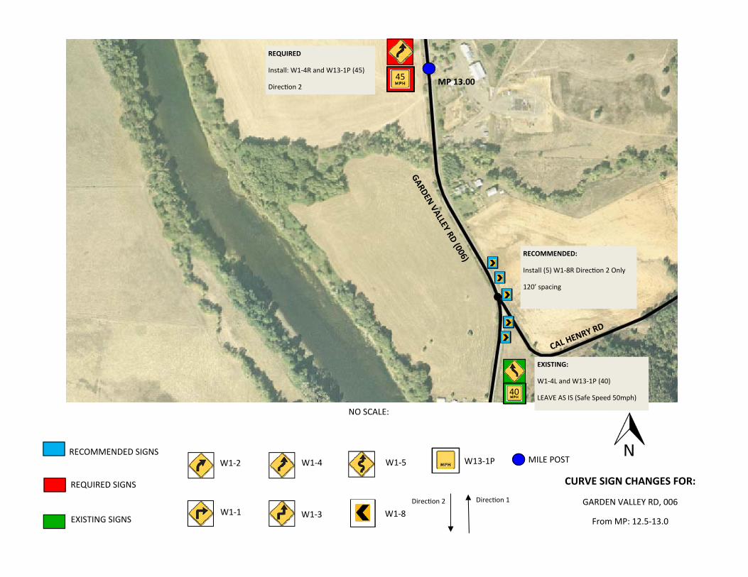
CURVE SIGN CHANGES FOR:
GARDEN VALLEY RD, 006
From MP: 12.5‐13.0
NO SCALE:
Direc on 2 Direc on 1
45
40
RECOMMENDED:
Install (5) W1‐8R Direc on 2 Only
120’ spacing
REQUIRED
Install: W1‐4R and W13‐1P (45)
Direc on 2
EXISTING:
W1‐4L and W13‐1P (40)
LEAVE AS IS (Safe Speed 50mph)
GARDEN VALLEY RD (006)
MP 13.00
CAL HEN
RY RD
RECOMMENDED SIGNS
REQUIRED SIGNS
EXISTING SIGNS
MILE POST W1‐2
W1‐1
W1‐4
W1‐3
W1‐5
W1‐8
W13‐1P
CURVE SIGN CHANGES FOR:
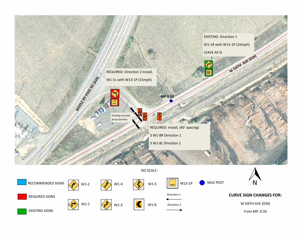
W SIXTH AVE (039)
From MP: 0.50
NO SCALE:
Direc on 1
Direc on 2
EXISTING: Direc on 1
W1‐1R with W13‐1P (10mph)
LEAVE AS IS
MP 0.50
10
Exis ng concrete jersey barriers
15
W SIXTH
AVE (0
39)
RIDD
LE BY‐PASS RD (039)
REQUIRED: Direc on 2 Install,
W1‐1L with W13‐1P (15mph)
REQUIRED: Install, (40’ spacing)
3 W1‐8R Direc on 1
3 W1‐8L Direc on 2
RECOMMENDED SIGNS
REQUIRED SIGNS
EXISTING SIGNS
MILE POST W1‐2
W1‐1
W1‐4
W1‐3
W1‐5
W1‐8
W13‐1P
CURVE SIGN CHANGES FOR:
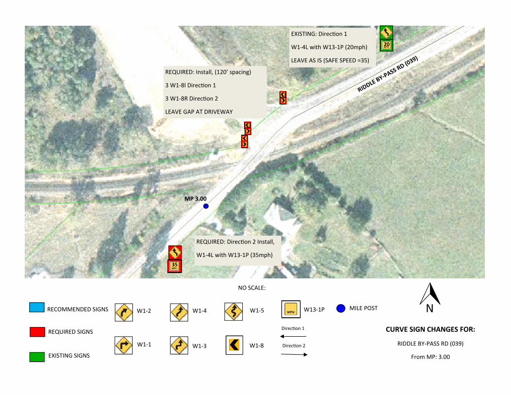
RIDDLE BY‐PASS RD (039)
From MP: 3.00
NO SCALE:
Direc on 1
Direc on 2
EXISTING: Direc on 1
W1‐4L with W13‐1P (20mph)
LEAVE AS IS (SAFE SPEED =35)
MP 3.00
RIDDLE
BY‐PA
SS RD (0
39)
REQUIRED: Direc on 2 Install,
W1‐4L with W13‐1P (35mph)
REQUIRED: Install, (120’ spacing)
3 W1‐8l Direc on 1
3 W1‐8R Direc on 2
LEAVE GAP AT DRIVEWAY
20
35
RECOMMENDED SIGNS
REQUIRED SIGNS
EXISTING SIGNS
MILE POST W1‐2
W1‐1
W1‐4
W1‐3
W1‐5
W1‐8
W13‐1P
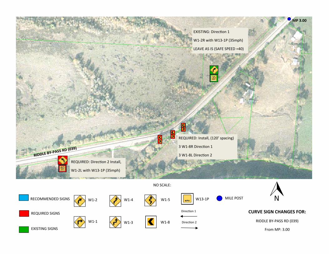
CURVE SIGN CHANGES FOR:
RIDDLE BY‐PASS RD (039)
From MP: 3.00
NO SCALE:
Direc on 1
Direc on 2
EXISTING: Direc on 1
W1‐2R with W13‐1P (35mph)
LEAVE AS IS (SAFE SPEED =40)
MP 3.00
RIDDLE BY‐PASS R
D (039)
REQUIRED: Direc on 2 Install,
W1‐2L with W13‐1P (35mph)
REQUIRED: Install, (120’ spacing)
3 W1‐8R Direc on 1
3 W1‐8L Direc on 2
35
40
RECOMMENDED SIGNS
REQUIRED SIGNS
EXISTING SIGNS
MILE POST W1‐2
W1‐1
W1‐4
W1‐3
W1‐5
W1‐8
W13‐1P
CURVE SIGN CHANGES FOR:
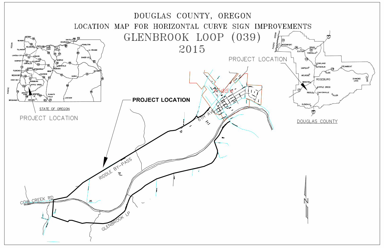
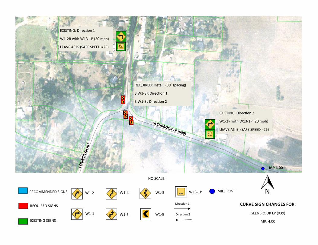
GLENBROOK LP (039)
MP: 4.00
NO SCALE:
Direc on 1
Direc on 2
EXISTING: Direc on 1
W1‐2R with W13‐1P (20 mph)
LEAVE AS IS (SAFE SPEED =25)
MP 4.00
GLENBROOK LP (039)
REQUIRED: Install, (80’ spacing)
3 W1‐8R Direc on 1
3 W1‐8L Direc on 2
20
20
EXISTING: Direc on 2
W1‐2R with W13‐1P (20 mph)
LEAVE AS IS (SAFE SPEED =25)
COUN
CIL C
R RD
RECOMMENDED SIGNS
REQUIRED SIGNS
EXISTING SIGNS
MILE POST W1‐2
W1‐1
W1‐4
W1‐3
W1‐5
W1‐8
W13‐1P
CURVE SIGN CHANGES FOR:
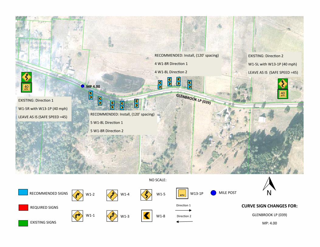
GLENBROOK LP (039)
MP: 4.00
NO SCALE:
Direc on 1
Direc on 2
EXISTING: Direc on 1
W1‐5R with W13‐1P (40 mph)
LEAVE AS IS (SAFE SPEED =45)
MP 4.00
GLENBROOK LP (039)
RECOMMENDED: Install, (120’ spacing)
4 W1‐8R Direc on 1
4 W1‐8L Direc on 2
EXISTING: Direc on 2
W1‐5L with W13‐1P (40 mph)
LEAVE AS IS (SAFE SPEED =45)
40
40
RECOMMENDED: Install, (120’ spacing)
5 W1‐8L Direc on 1
5 W1‐8R Direc on 2
RECOMMENDED SIGNS
REQUIRED SIGNS
EXISTING SIGNS
MILE POST W1‐2
W1‐1
W1‐4
W1‐3
W1‐5
W1‐8
W13‐1P
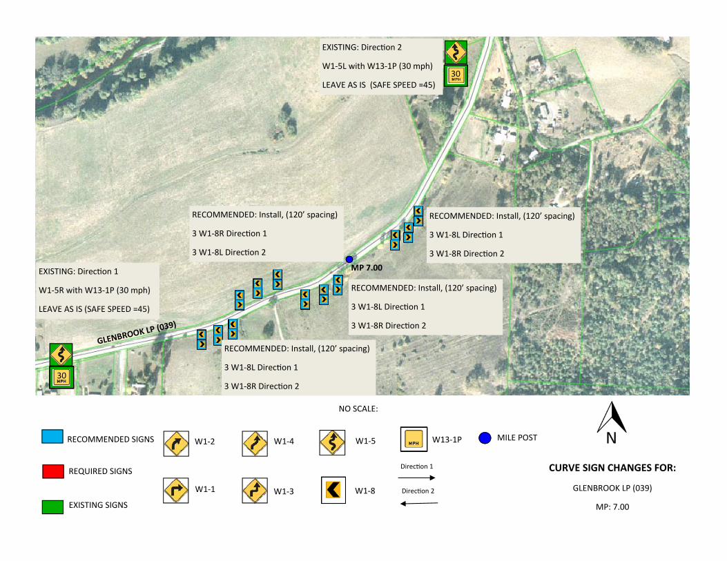
CURVE SIGN CHANGES FOR:
GLENBROOK LP (039)
MP: 7.00
NO SCALE:
Direc on 1
Direc on 2
EXISTING: Direc on 1
W1‐5R with W13‐1P (30 mph)
LEAVE AS IS (SAFE SPEED =45)
MP 7.00
GLENBROOK LP
(039)
RECOMMENDED: Install, (120’ spacing)
3 W1‐8L Direc on 1
3 W1‐8R Direc on 2
EXISTING: Direc on 2
W1‐5L with W13‐1P (30 mph)
LEAVE AS IS (SAFE SPEED =45)
30
30
RECOMMENDED: Install, (120’ spacing)
3 W1‐8L Direc on 1
3 W1‐8R Direc on 2
RECOMMENDED: Install, (120’ spacing)
3 W1‐8L Direc on 1
3 W1‐8R Direc on 2
RECOMMENDED: Install, (120’ spacing)
3 W1‐8R Direc on 1
3 W1‐8L Direc on 2
RECOMMENDED SIGNS
REQUIRED SIGNS
EXISTING SIGNS
MILE POST W1‐2
W1‐1
W1‐4
W1‐3
W1‐5
W1‐8
W13‐1P
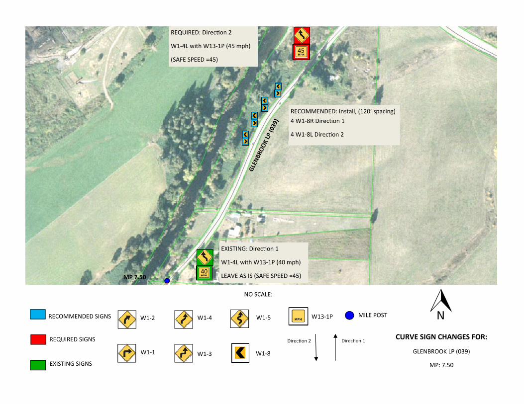
CURVE SIGN CHANGES FOR:
GLENBROOK LP (039)
MP: 7.50
NO SCALE:
Direc on 1 Direc on 2
EXISTING: Direc on 1
W1‐4L with W13‐1P (40 mph)
LEAVE AS IS (SAFE SPEED =45) MP 7.50
GLEN
BROO
K LP (039)
REQUIRED: Direc on 2
W1‐4L with W13‐1P (45 mph)
(SAFE SPEED =45)
40
45
RECOMMENDED: Install, (120’ spacing)4 W1‐8R Direc on 1
4 W1‐8L Direc on 2
RECOMMENDED SIGNS
REQUIRED SIGNS
EXISTING SIGNS
MILE POST
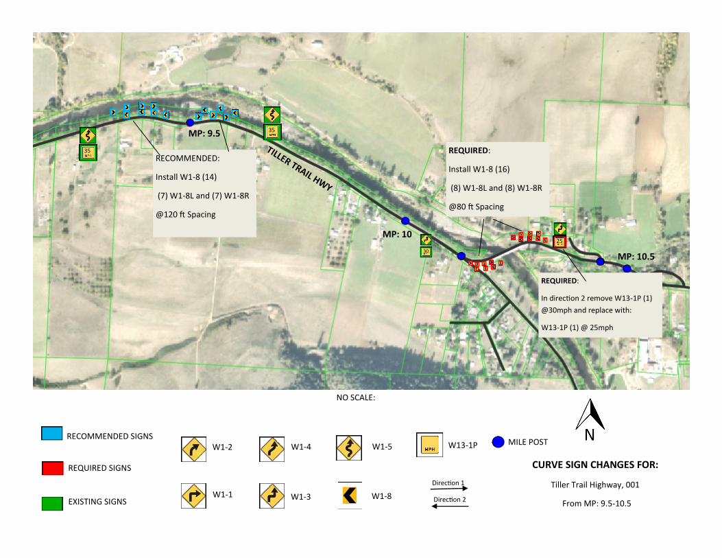
MP: 9.5
W1-2
W1-1
W1-4
W1-3
W1-5
W1-8
W13-1P
35
CURVE SIGN CHANGES FOR:
Tiller Trail Highway, 001
From MP: 9.5-10.5
NO SCALE:
MP: 10
MP: 10.5 30
25
35 TILLER TRAIL HWY
RECOMMENDED:
Install W1-8 (14)
(7) W1-8L and (7) W1-8R
@120 ft Spacing
REQUIRED:
Install W1-8 (16)
(8) W1-8L and (8) W1-8R
@80 ft Spacing
REQUIRED:
In direction 2 remove W13-1P (1)
@30mph and replace with:
W13-1P (1) @ 25mph
Direction 1
Direction 2
RECOMMENDED SIGNS
REQUIRED SIGNS
EXISTING SIGNS
MILE POST W1-2
W1-1
W1-4
W1-3
W1-5
W1-8
W13-1P
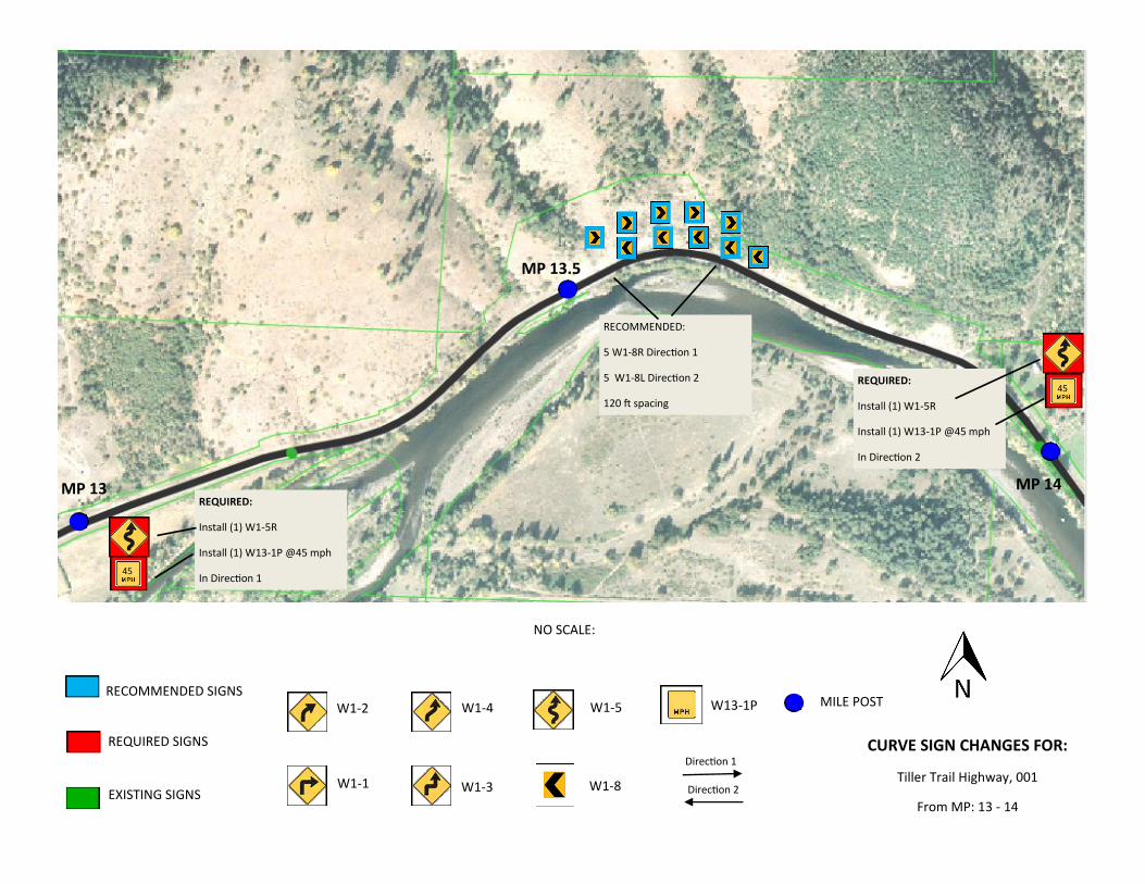
CURVE SIGN CHANGES FOR:
Tiller Trail Highway, 001
From MP: 13 - 14
NO SCALE:
Direction 1
Direction 2
45
45
RECOMMENDED:
5 W1-8R Direction 1
5 W1-8L Direction 2
120 ft spacing
REQUIRED:
Install (1) W1-5R
Install (1) W13-1P @45 mph
In Direction 1
REQUIRED:
Install (1) W1-5R
Install (1) W13-1P @45 mph
In Direction 2
MP 13.5
MP 13 MP 14
RECOMMENDED SIGNS
REQUIRED SIGNS
EXISTING SIGNS
MILE POST W1-2
W1-1
W1-4
W1-3
W1-5
W1-8
W13-1P
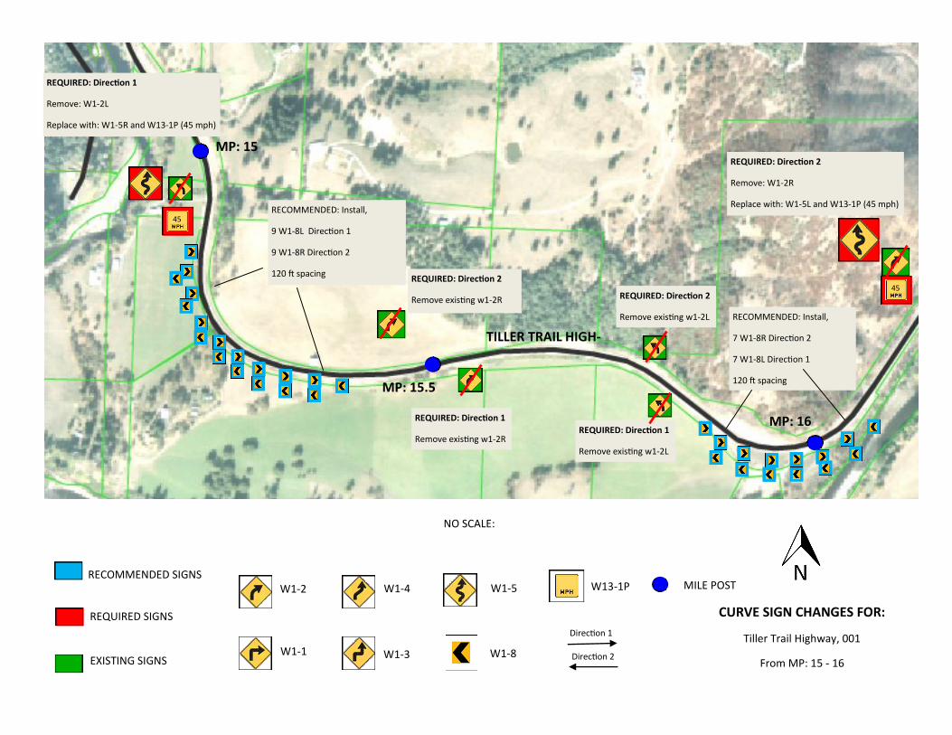
CURVE SIGN CHANGES FOR:
Tiller Trail Highway, 001
From MP: 15 - 16
NO SCALE:
45
MP: 15
MP: 15.5
MP: 16
RECOMMENDED: Install,
9 W1-8L Direction 1
9 W1-8R Direction 2
120 ft spacing
TILLER TRAIL HIGH-
Direction 1
Direction 2
45
RECOMMENDED: Install,
7 W1-8R Direction 2
7 W1-8L Direction 1
120 ft spacing
REQUIRED: Direction 2
Remove: W1-2R
Replace with: W1-5L and W13-1P (45 mph)
REQUIRED: Direction 1
Remove existing w1-2L
REQUIRED: Direction 2
Remove existing w1-2R
REQUIRED: Direction 1
Remove: W1-2L
Replace with: W1-5R and W13-1P (45 mph)
REQUIRED: Direction 2
Remove existing w1-2L
REQUIRED: Direction 1
Remove existing w1-2R
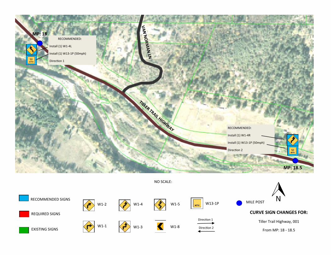
RECOMMENDED SIGNS
REQUIRED SIGNS
EXISTING SIGNS
MILE POST W1-2
W1-1
W1-4
W1-3
W1-5
W1-8
W13-1P
CURVE SIGN CHANGES FOR:
Tiller Trail Highway, 001
From MP: 18 - 18.5
NO SCALE:
Direction 1
Direction 2
50
50
RECOMMENDED:
Install (1) W1-4L
Install (1) W13-1P (50mph)
Direction 1
RECOMMENDED:
Install (1) W1-4R
Install (1) W13-1P (50mph)
Direction 2
MP: 18.5
MP: 18
TILLER TRAIL HIGHWAY
VA
N N
OR
MA
N LN
TM
200
TM200Effective Date: December 1, 2018 - May 31, 2019
TM
200.d
gn 1-3-2
017
N/ACALC. BOOK NO. BASELINE REPORT DATE
the current Oregon Standard Specifications
All material and workmanship shall be in accordance withNOTE:
DATE REVISION DESCRIPTION
OREGON STANDARD DRAWINGS
2018
SIGN INSTALLATION DETAILS
The selection and use of this
Standard Drawing, while de-
signed in accordance with
generally accepted engineer-
ing principles and practices,
is the sole responsibility of
the user and should not be
used without consulting a
Registered Professional En-
gineer.
plotfile_TM200s_500s.dgn :: Default 6/15/2018 3:56:29 PM hwyr20m
1/08/18 Adjusted slope line on Mounting Height detail for clarity
01/08/2018
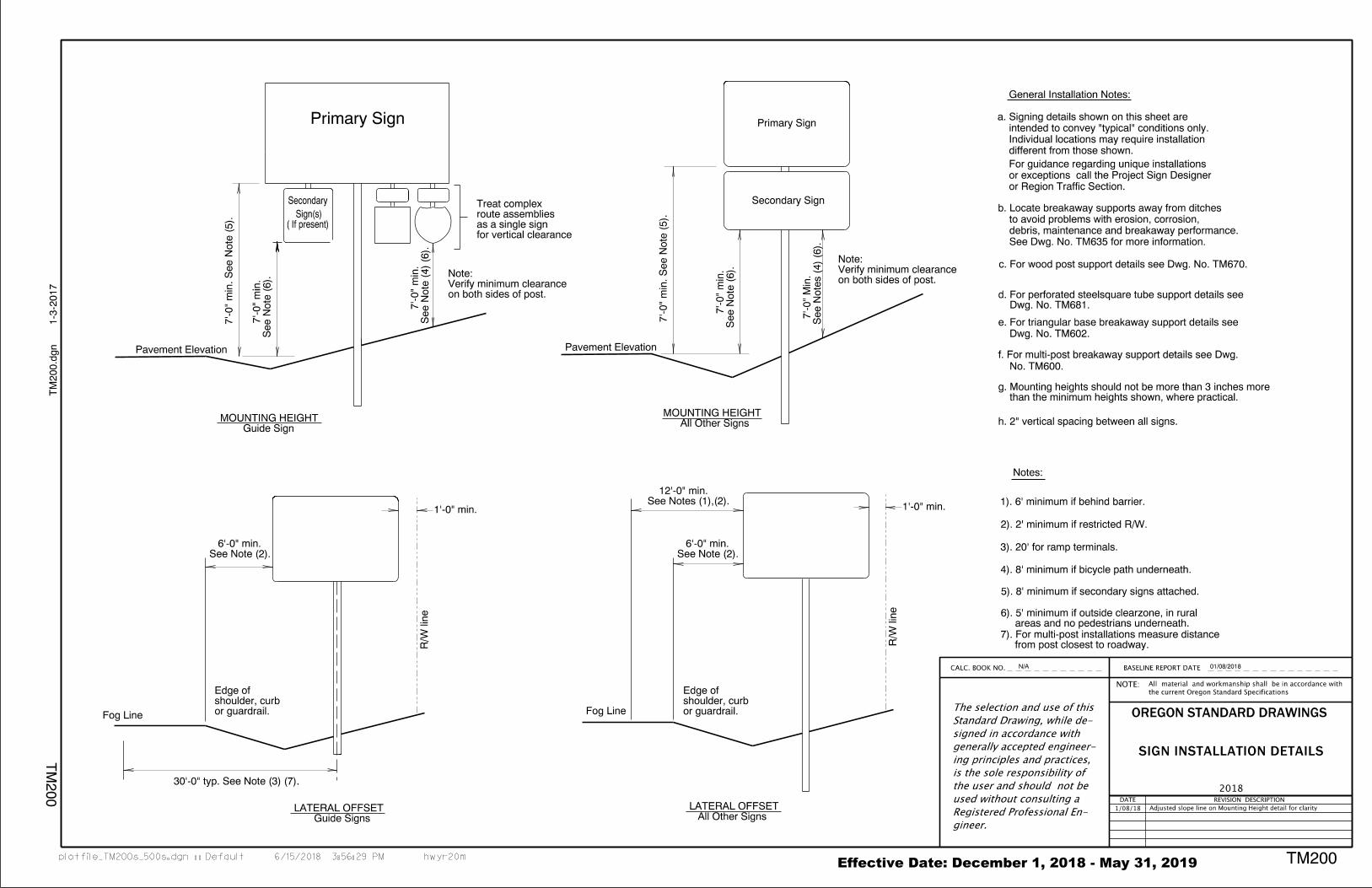
Secondary
Primary Sign
Pavement Elevation
c. For wood post support details see Dwg. No. TM670.
to avoid problems with erosion, corrosion,
debris, maintenance and breakaway performance.
See Dwg. No. TM635 for more information.
a. Signing details shown on this sheet are
intended to convey "typical" conditions only.
different from those shown.
For guidance regarding unique installations
or exceptions call the Project Sign Designer
b. Locate breakaway supports away from ditches
or Region Traffic Section.
e. For triangular base breakaway support details see
Dwg. No. TM602.
f. For multi-post breakaway support details see Dwg.
No. TM600.
Pavement Elevation
than the minimum heights shown, where practical.g. Mounting heights should not be more than 3 inches more
Guide SignsLATERAL OFFSET
R/W line
R/W line
All Other SignsLATERAL OFFSET
4). 8' minimum if bicycle path underneath.
2). 2' minimum if restricted R/W.
3). 20' for ramp terminals.
5). 8' minimum if secondary signs attached.
1'-0" min.1'-0" min.See Notes (1),(2). 12'-0" min.
Dwg. No. TM681.d. For perforated steelsquare tube support details see
h. 2" vertical spacing between all signs. Guide SignMOUNTING HEIGHT
All Other SignsMOUNTING HEIGHT
See Note (2). 6'-0" min.
See Note (2). 6'-0" min.
7'-0"
min. See N
ote (5).
See N
ote (6).
7'-0"
min.
7'-0"
min. See N
ote (5).
See N
ote (6).
7'-0"
min.
See N
otes (4) (6).
7'-0"
Min.
on both sides of post.Verify minimum clearanceNote:
or guardrail. shoulder, curbEdge of
Fog Line or guardrail. shoulder, curbEdge of
See N
ote (4) (6).
7'-0"
min.
on both sides of post.Verify minimum clearanceNote:
areas and no pedestrians underneath.6). 5' minimum if outside clearzone, in rural
from post closest to roadway.7). For multi-post installations measure distance
Primary Sign
for vertical clearanceas a single signroute assembliesTreat complex
( If present) Sign(s)
Secondary Sign
General Installation Notes:
Individual locations may require installation
1). 6' minimum if behind barrier.
Notes:
30'-0" typ. See Note (3) (7).
Fog Line
The selection and use of this
Standard Drawing, while de-
signed in accordance with
generally accepted engineer-
ing principles and practices,
is the sole responsibility of
the user and should not be
used without consulting a
Registered Professional En-
gineer.
Effective Date: December 1, 2018 – May 31, 2019
CALC. BOOK NO. BASELINE REPORT DATE
the current Oregon Standard Specifications
All material and workmanship shall be in accordance withNOTE:
DATE REVISION DESCRIPTION
OREGON STANDARD DRAWINGS
2018
TM676
tm676.d
gn 1
0-J
UL-2
017
TM
676
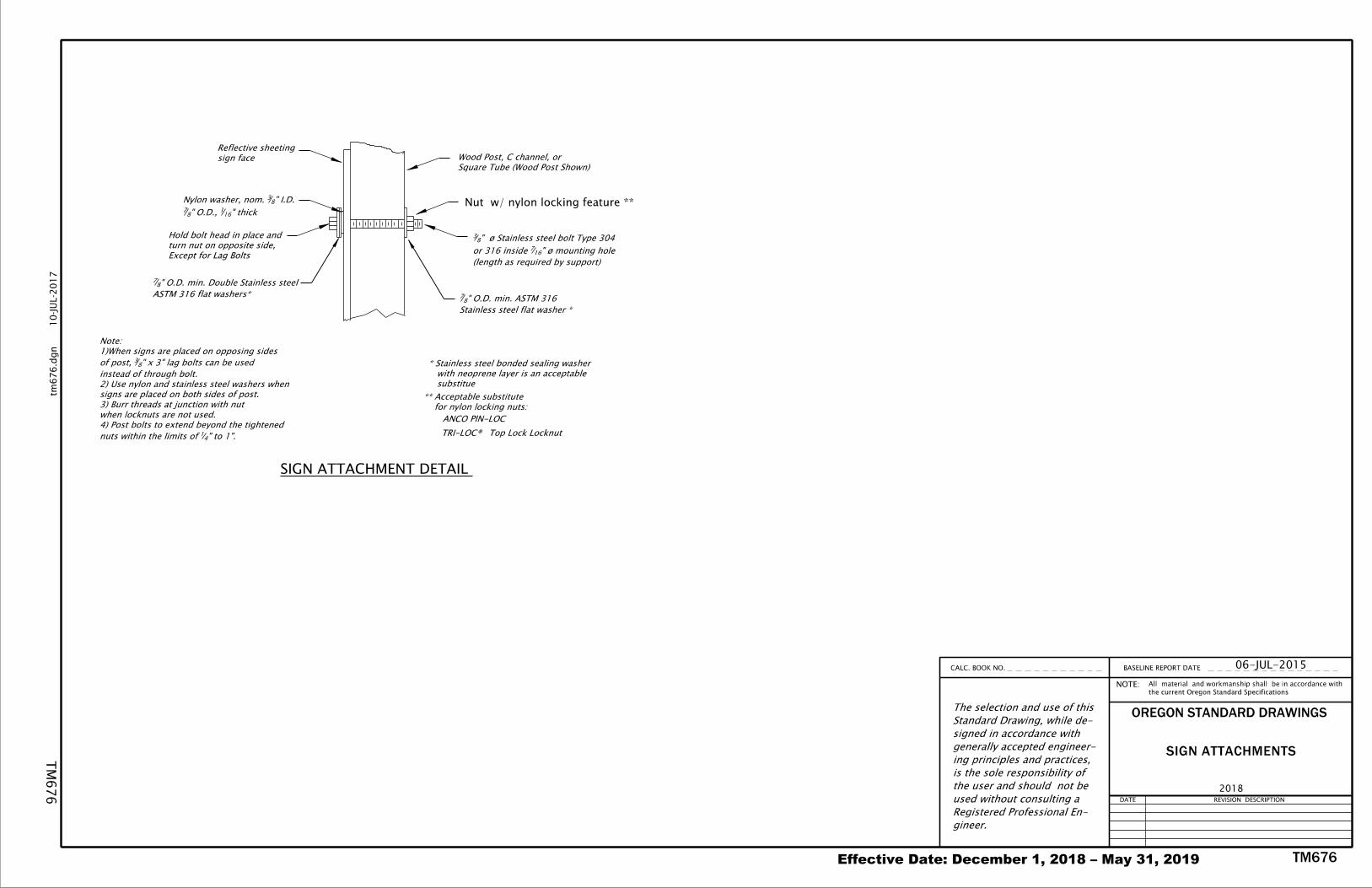
SIGN ATTACHMENTS
06-JUL-2015
(length as required by support)
" ø mounting hole167or 316 inside
" ø Stainless steel bolt Type 30483
Stainless steel flat washer *
" O.D. min. ASTM 31687
Square Tube (Wood Post Shown)
Wood Post, C channel, or sign face
Reflective sheeting
ANCO PIN-LOC
Top Lock Locknut
for nylon locking nuts:
** Acceptable substitute
" thick161" O.D., 8
7
" I.D.83Nylon washer, nom.
" to 1".41nuts within the limits of
4) Post bolts to extend beyond the tightened
when locknuts are not used.
3) Burr threads at junction with nut
signs are placed on both sides of post.
2) Use nylon and stainless steel washers when
instead of through bolt.
" x 3" lag bolts can be used83of post,
1)When signs are placed on opposing sides
Note:
Except for Lag Bolts
turn nut on opposite side,
Hold bolt head in place and
ASTM 316 flat washers*
" O.D. min. Double Stainless steel 87
SIGN ATTACHMENT DETAIL
TRI-LOC®
substitue
with neoprene layer is an acceptable
* Stainless steel bonded sealing washer
Nut w/ nylon locking feature **
Registered Professional Engineer.
be used without consulting a
sibility of the user and should not
and practices, is the sole respon-
accepted engineering principles
in accordance with generally
Standard Drawing, while designed
The selection and use of this
Effective Date: December 1, 2018 - May 31, 2019
2018
C
100'|
100'|
Fla
gger
Fla
gger
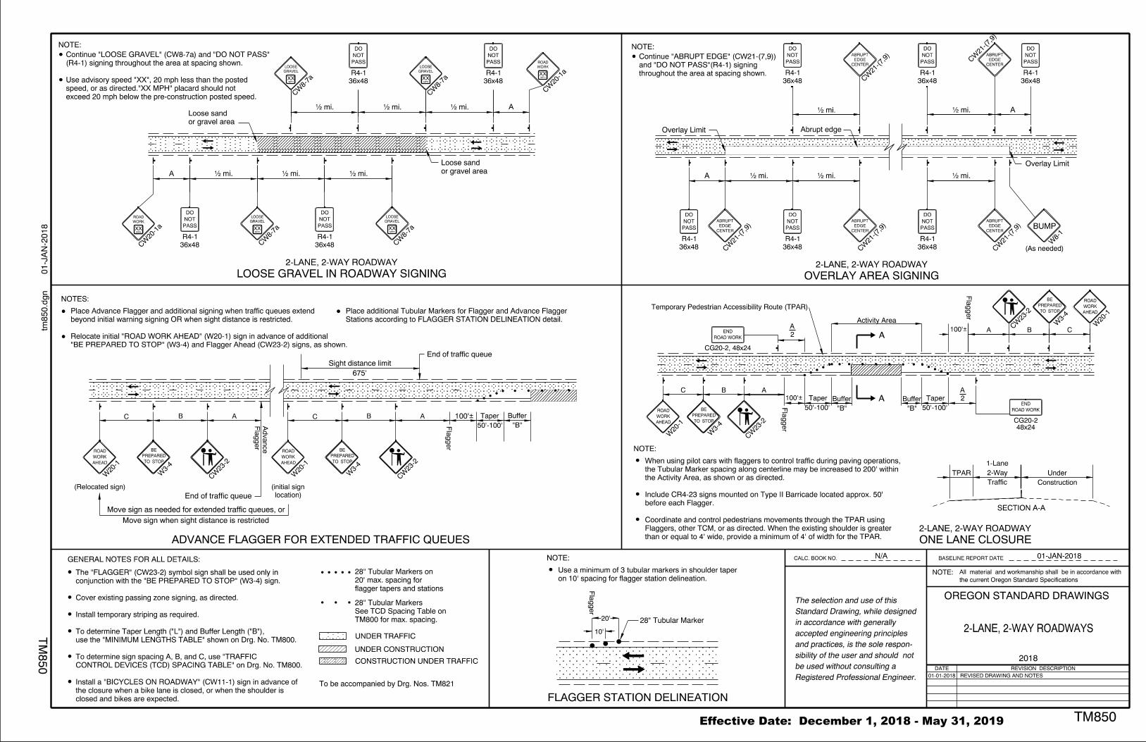
ONE LANE CLOSURE
2-LANE, 2-WAY ROADWAY
2-LANE, 2-WAY ROADWAY
GENERAL NOTES FOR ALL DETAILS:
NOTES:
C
Fla
gger
Fla
gger
Advance
ADVANCE FLAGGER FOR EXTENDED TRAFFIC QUEUES
TM800 for max. spacing.
See TCD Spacing Table on
28" Tubular Markers
UNDER TRAFFIC
UNDER CONSTRUCTION
CONSTRUCTION UNDER TRAFFIC
End of traffic queue
Move sign when sight distance is restricted
End of traffic queue
675'
Sight distance limit
NOTE:
PASS
NOT
DO
panelStyle:regulatory.ssipanelName:namepanelQuantity:1panelStation:nonepanelMaterial:0legendMaterial:0panelMounting:0panelWidthLock:1panelHeightLock:1marginAlign:9panelRoundCorners:0panelSizes:constructPanelMode:0constructPanels:36|24|18
PASS
NOT
DO
panelStyle:regulatory.ssipanelName:namepanelQuantity:1panelStation:nonepanelMaterial:0legendMaterial:0panelMounting:0panelWidthLock:1panelHeightLock:1marginAlign:9panelRoundCorners:0panelSizes:constructPanelMode:0constructPanels:36|24|18
PASS
NOT
DO
panelStyle:regulatory.ssipanelName:namepanelQuantity:1panelStation:nonepanelMaterial:0legendMaterial:0panelMounting:0panelWidthLock:1panelHeightLock:1marginAlign:9panelRoundCorners:0panelSizes:constructPanelMode:0constructPanels:36|24|18panelStyle:construction_warning.ssipanelName:namepanelQuantity:1panelStation:nonepanelMaterial:0legendMaterial:0panelMounting:0panelWidthLock:0panelHeightLock:0marginAlign:9panelRoundCorners:0panelSizes:constructPanelMode:0constructPanels:36|24|18
CENTER
EDGE
ABRUPT
panelStyle:construction_warning.ssipanelName:namepanelQuantity:1panelStation:nonepanelMaterial:0legendMaterial:0panelMounting:0panelWidthLock:0panelHeightLock:0marginAlign:9panelRoundCorners:0panelSizes:constructPanelMode:0constructPanels:36|24|18
CENTER
EDGE
ABRUPT
panelStyle:construction_warning.ssipanelName:namepanelQuantity:1panelStation:nonepanelMaterial:0legendMaterial:0panelMounting:0panelWidthLock:0panelHeightLock:0marginAlign:9panelRoundCorners:0panelSizes:constructPanelMode:0constructPanels:36|24|18
CENTER
EDGE
ABRUPT
BUMP
panelStyle:construction_warning.ssipanelName:namepanelQuantity:1panelStation:nonepanelMaterial:0legendMaterial:0panelMounting:0panelWidthLock:0panelHeightLock:0marginAlign:9panelRoundCorners:0panelSizes:constructPanelMode:0constructPanels:36|24|18
panelStyle:regulatory.ssipanelName:namepanelQuantity:1panelStation:nonepanelMaterial:0legendMaterial:0panelMounting:0panelWidthLock:1panelHeightLock:1marginAlign:9panelRoundCorners:0panelSizes:constructPanelMode:0constructPanels:36|24|18 panelStyle:regulatory.ssipanelName:namepanelQuantity:1panelStation:nonepanelMaterial:0legendMaterial:0panelMounting:0panelWidthLock:1panelHeightLock:1marginAlign:9panelRoundCorners:0panelSizes:constructPanelMode:0constructPanels:36|24|18
PASS
NOT
DO
panelStyle:regulatory.ssipanelName:namepanelQuantity:1panelStation:nonepanelMaterial:0legendMaterial:0panelMounting:0panelWidthLock:1panelHeightLock:1marginAlign:9panelRoundCorners:0panelSizes:constructPanelMode:0constructPanels:36|24|18
PASS
NOT
DO
panelStyle:regulatory.ssipanelName:namepanelQuantity:1panelStation:nonepanelMaterial:0legendMaterial:0panelMounting:0panelWidthLock:1panelHeightLock:1marginAlign:9panelRoundCorners:0panelSizes:constructPanelMode:0constructPanels:36|24|18
panelStyle:construction_warning.ssipanelName:namepanelQuantity:1panelStation:nonepanelMaterial:0legendMaterial:0panelMounting:0panelWidthLock:0panelHeightLock:0marginAlign:9panelRoundCorners:0panelSizes:constructPanelMode:0constructPanels:36|24|18
CENTER
EDGE
ABRUPT
panelStyle:construction_warning.ssipanelName:namepanelQuantity:1panelStation:nonepanelMaterial:0legendMaterial:0panelMounting:0panelWidthLock:0panelHeightLock:0marginAlign:9panelRoundCorners:0panelSizes:constructPanelMode:0constructPanels:36|24|18
CENTER
EDGE
ABRUPT
PASS
NOT
DO
panelStyle:regulatory.ssipanelName:namepanelQuantity:1panelStation:nonepanelMaterial:0legendMaterial:0panelMounting:0panelWidthLock:1panelHeightLock:1marginAlign:9panelRoundCorners:0panelSizes:constructPanelMode:0constructPanels:36|24|18
B A
CBA
(Relocated sign)
NOTE:
"B"
Buffer
"B"
Buffer
B A C B A
"B"
Buffer
To be accompanied by Drg. Nos. TM821
2-LANE, 2-WAY ROADWAYS
50'-100'
Taper
50'-100'
Taper
50'-100'
Taper
N/A
• mi.
• mi.
• mi.
• mi.• mi.
Overlay Limit Abrupt edge
Overlay Limit
100'|
2
A
2
A
NOTE:
2-LANE, 2-WAY ROADWAY
• mi.
MPH
panelStyle:construction_warning.ssipanelName:namepanelQuantity:1panelStation:nonepanelMaterial:0legendMaterial:0panelMounting:0panelWidthLock:0panelHeightLock:0marginAlign:9panelRoundCorners:0panelSizes:constructPanelMode:0constructPanels:36|24|18
WORK
ROAD
• mi. • mi.
PASS
NOT
DO
panelStyle:regulatory.ssipanelName:namepanelQuantity:1panelStation:nonepanelMaterial:0legendMaterial:0panelMounting:0panelWidthLock:1panelHeightLock:1marginAlign:9panelRoundCorners:0panelSizes:constructPanelMode:0constructPanels:36|24|18
PASS
NOT
DO
panelStyle:regulatory.ssipanelName:namepanelQuantity:1panelStation:nonepanelMaterial:0legendMaterial:0panelMounting:0panelWidthLock:1panelHeightLock:1marginAlign:9panelRoundCorners:0panelSizes:constructPanelMode:0constructPanels:36|24|18
MPH
panelStyle:construction_warning.ssipanelName:namepanelQuantity:1panelStation:nonepanelMaterial:0legendMaterial:0panelMounting:0panelWidthLock:0panelHeightLock:0marginAlign:9panelRoundCorners:0panelSizes:constructPanelMode:0constructPanels:36|24|18
GRAVEL
LOOSE
MPH
panelStyle:construction_warning.ssipanelName:namepanelQuantity:1panelStation:nonepanelMaterial:0legendMaterial:0panelMounting:0panelWidthLock:0panelHeightLock:0marginAlign:9panelRoundCorners:0panelSizes:constructPanelMode:0constructPanels:36|24|18
GRAVEL
LOOSE
or gravel area
Loose sand
LOOSE GRAVEL IN ROADWAY SIGNING
location)
(initial sign
flagger tapers and stations
20' max. spacing for
28" Tubular Markers on
OVERLAY AREA SIGNING
01-JAN-2018
Move sign as needed for extended traffic queues, or
TM850
NOTE:the current Oregon Standard Specifications
All material and workmanship shall be in accordance with
OREGON STANDARD DRAWINGS
DATE REVISION DESCRIPTION
BASELINE REPORT DATECALC. BOOK NO.
TM
850
tm850.d
gn 0
1-J
AN-2
018 XX XX XX
• mi.
or gravel area
Loose sand
• mi. • mi.
MPH
panelStyle:construction_warning.ssipanelName:namepanelQuantity:1panelStation:nonepanelMaterial:0legendMaterial:0panelMounting:0panelWidthLock:0panelHeightLock:0marginAlign:9panelRoundCorners:0panelSizes:constructPanelMode:0constructPanels:36|24|18
GRAVEL
LOOSE
XXMPH
panelStyle:construction_warning.ssipanelName:namepanelQuantity:1panelStation:nonepanelMaterial:0legendMaterial:0panelMounting:0panelWidthLock:0panelHeightLock:0marginAlign:9panelRoundCorners:0panelSizes:constructPanelMode:0constructPanels:36|24|18
GRAVEL
LOOSE
XX
MPH
panelStyle:construction_warning.ssipanelName:namepanelQuantity:1panelStation:nonepanelMaterial:0legendMaterial:0panelMounting:0panelWidthLock:0panelHeightLock:0marginAlign:9panelRoundCorners:0panelSizes:constructPanelMode:0constructPanels:36|24|18
WORK
ROAD
XX
AHEAD
WORK
ROAD
panelStyle:construction_warning.ssipanelName:namepanelQuantity:1panelStation:nonepanelMaterial:0legendMaterial:0panelMounting:0panelWidthLock:0panelHeightLock:0marginAlign:9panelRoundCorners:0panelSizes:constructPanelMode:0constructPanels:36|24|18
STOP
PREPARED
BE
TO
panelStyle:construction_warning.ssipanelName:namepanelQuantity:1panelStation:nonepanelMaterial:0legendMaterial:0panelMounting:0panelWidthLock:0panelHeightLock:0marginAlign:9panelRoundCorners:0panelSizes:constructPanelMode:0constructPanels:36|24|18 panelStyle:construction_warning.ssipanelName:namepanelQuantity:1panelStation:nonepanelMaterial:0legendMaterial:0panelMounting:0panelWidthLock:0panelHeightLock:0marginAlign:9panelRoundCorners:0panelSizes:constructPanelMode:0constructPanels:36|24|18
(As needed)
AHEAD
WORK
ROAD
panelStyle:construction_warning.ssipanelName:namepanelQuantity:1panelStation:nonepanelMaterial:0legendMaterial:0panelMounting:0panelWidthLock:0panelHeightLock:0marginAlign:9panelRoundCorners:0panelSizes:constructPanelMode:0constructPanels:36|24|18
STOP
PREPARED
BE
TO
panelStyle:construction_warning.ssipanelName:namepanelQuantity:1panelStation:nonepanelMaterial:0legendMaterial:0panelMounting:0panelWidthLock:0panelHeightLock:0marginAlign:9panelRoundCorners:0panelSizes:constructPanelMode:0constructPanels:36|24|18 panelStyle:construction_warning.ssipanelName:namepanelQuantity:1panelStation:nonepanelMaterial:0legendMaterial:0panelMounting:0panelWidthLock:0panelHeightLock:0marginAlign:9panelRoundCorners:0panelSizes:constructPanelMode:0constructPanels:36|24|18
panelStyle:construction_warning.ssipanelName:namepanelQuantity:1panelStation:nonepanelMaterial:0legendMaterial:0panelMounting:0panelWidthLock:0panelHeightLock:0marginAlign:9panelRoundCorners:0panelSizes:constructPanelMode:0constructPanels:36|24|18
AHEAD
WORK
ROAD
panelStyle:construction_warning.ssipanelName:namepanelQuantity:1panelStation:nonepanelMaterial:0legendMaterial:0panelMounting:0panelWidthLock:0panelHeightLock:0marginAlign:9panelRoundCorners:0panelSizes:constructPanelMode:0constructPanels:36|24|18
STOP
PREPARED
BE
TO
panelStyle:construction_warning.ssipanelName:namepanelQuantity:1panelStation:nonepanelMaterial:0legendMaterial:0panelMounting:0panelWidthLock:0panelHeightLock:0marginAlign:9panelRoundCorners:0panelSizes:constructPanelMode:0constructPanels:36|24|18
NOTE:
FLAGGER STATION DELINEATION
Fla
gger
10'
20' 28" Tubular Marker
on 10' spacing for flagger station delineation.
Use a minimum of 3 tubular markers in shoulder taper
A
A A
A
Stations according to FLAGGER STATION DELINEATION detail.
Place additional Tubular Markers for Flagger and Advance Flagger
exceed 20 mph below the pre-construction posted speed.
speed, or as directed."XX MPH" placard should not
Use advisory speed "XX", 20 mph less than the posted
(R4-1) signing throughout the area at spacing shown.
Continue "LOOSE GRAVEL" (CW8-7a) and "DO NOT PASS"
CW8-7a
CW8-7a
CW8-7a
CW8-7a
36x48
R4-1
PASS
NOT
DO
panelStyle:regulatory.ssipanelName:namepanelQuantity:1panelStation:nonepanelMaterial:0legendMaterial:0panelMounting:0panelWidthLock:1panelHeightLock:1marginAlign:9panelRoundCorners:0panelSizes:constructPanelMode:0constructPanels:36|24|18
36x48
R4-1
PASS
NOT
DO
panelStyle:regulatory.ssipanelName:namepanelQuantity:1panelStation:nonepanelMaterial:0legendMaterial:0panelMounting:0panelWidthLock:1panelHeightLock:1marginAlign:9panelRoundCorners:0panelSizes:constructPanelMode:0constructPanels:36|24|18
36x48
R4-1
36x48
R4-1
CW20-1a
CW20-1a
"BE PREPARED TO STOP" (W3-4) and Flagger Ahead (CW23-2) signs, as shown.
Relocate initial "ROAD WORK AHEAD" (W20-1) sign in advance of additional
beyond initial warning signing OR when sight distance is restricted.
Place Advance Flagger and additional signing when traffic queues extend
W20-1
W3-4
CW23-2
W20-1
W3-4
CW23-2
closed and bikes are expected.
the closure when a bike lane is closed, or when the shoulder is
Install a "BICYCLES ON ROADWAY" (CW11-1) sign in advance of
CONTROL DEVICES (TCD) SPACING TABLE" on Drg. No. TM800.
To determine sign spacing A, B, and C, use "TRAFFIC
use the "MINIMUM LENGTHS TABLE" shown on Drg. No. TM800.
To determine Taper Length ("L") and Buffer Length ("B"),
Install temporary striping as required.
Cover existing passing zone signing, as directed.
conjunction with the "BE PREPARED TO STOP" (W3-4) sign.
The "FLAGGER" (CW23-2) symbol sign shall be used only in
CW21-(7,9)
CW21-(7,9)
CW21-(7,9)
CW21-(7,9)
CW21-(7,9)
W8-1
36x48
R4-1
36x48
R4-1
36x48
R4-1
36x48
R4-1
36x48
R4-1
36x48
R4-1throughout the area at spacing shown.
and "DO NOT PASS"(R4-1) signing
Continue "ABRUPT EDGE" (CW21-(7,9))
48x24CG20-2
ROAD WORK
END
panelStyle:regulatory.ssipanelName:namepanelQuantity:1panelStation:nonepanelMaterial:0legendMaterial:0panelMounting:0panelWidthLock:1panelHeightLock:1marginAlign:9panelRoundCorners:0panelSizes:constructPanelMode:0constructPanels:36|24|18
CW23-2
W3-4
W20-1
W20-1
W3-4
CW23-2
CG20-2, 48x24
ROAD WORK
END
panelStyle:regulatory.ssipanelName:namepanelQuantity:1panelStation:nonepanelMaterial:0legendMaterial:0panelMounting:0panelWidthLock:1panelHeightLock:1marginAlign:9panelRoundCorners:0panelSizes:constructPanelMode:0constructPanels:36|24|18
A
A
Activity Area
SECTION A-A
Construction
Under
Traffic
2-Way
1-Lane
TPAR
than or equal to 4' wide, provide a minimum of 4' of width for the TPAR.
Flaggers, other TCM, or as directed. When the existing shoulder is greater
Coordinate and control pedestrians movements through the TPAR using
before each Flagger.
Include CR4-23 signs mounted on Type II Barricade located approx. 50'
the Activity Area, as shown or as directed.
the Tubular Marker spacing along centerline may be increased to 200' within
When using pilot cars with flaggers to control traffic during paving operations,
Temporary Pedestrian Accessibility Route (TPAR)
01-01-2018 REVISED DRAWING AND NOTES