custom home - verradoall illustrations reference architectural direction only and do not represent...
TRANSCRIPT

CUSTOM HOME Des ign Guide l ines
THIRD EDITIONJULY 21, 2015

All illustrations reference architectural direction only and do not represent actual Homes specific to this Site.
This material is not intended to constitute an offering in violation of the law of any jurisdiction. Obtain the Public Report or its equivalent, required by Federal and State Law, and read it before signing anything. No Federal or State agency has judged the merits or value, if any, of this property. No binding offer to sell or lease may be made or accepted prior to issuance of the final Arizona Subdivision Public Report for the property. These materials and the features and amenities depicted herein are based upon current development plans, which are subject to change without notice. No guarantee is made that the features and amenities depicted by artists’ renderings or otherwise described will be built, or, if built, will be the same type, size, or nature as depicted or described. Warning: The Department of Real Estate has not inspected, examined, or qualified this offering. While the conceptual designs depicted conform to Verrado Design Guidelines, the designs may not be considered compatible due to the specific restrictions, adjacent home designs, etc. The desired style direction for your home should be discussed at the required pre-design meeting.
© 2005 DMB White Tank, LLC and Dale Gardon Design, LLC
10 9 8 7 6 5 4 3 2
06/2005, Revised July 21, 2015
DMB White Tank, LLCLand Development Coordination
Dale Gardon Design, LLCDesign Guideline Author and Graphic Design
DTJ DesignLot-specific Special Design Criteria
Jeff Simutis, ASAIIllustration

Contents at a Glance
SECTION ONE Design Philosophy and Introduction
SECTION TWO Site Design
SECTION THREE General Architectural Design Considerations
SECTION FOUR Detailed Architectural Design Considerations
SECTION FIVE Architectural Styles
SECTION SIX Landscape Design
SECTION SEVEN Exterior Lighting
SECTION EIGHT Design Review Procedures
SECTION NINE Construction Regulations
APPENDIX A Defined Terms
APPENDIX B Lot-specific Special Design Criteria—Parcel 5.803 and 5.804
APPENDIX C Lot-specific Special Design Criteria—Parcel 3.101
APPENDIX D Approved Roof Materials

vTABLE OF CONTENTS
V E R R A D O CUSTOM HOME DESIGN GUIDEL INES
JULU 21, 2015
Table of Contents
SECTION ONEDesign Philosophy and Introduction
1.1 The Value of This Guide ...............................................................................1.2
1.2 A Vision for Verrado Custom Homes .............................................................1.3
1.2.1 Unified Town Concept .......................................................................... 1.3
1.2.2 Reflecting Regional Heritage .................................................................. 1.3
1.2.3 Location and Setting ............................................................................. 1.3
1.2.4 Community Themes .............................................................................. 1.3
1.2.5 Guiding Principles for Design ................................................................. 1.5
1.2.6 Design Integrity .................................................................................... 1.7
SECTION TWOSite Design
2.1 The Home Site .............................................................................................2.3
2.2 General Site Design Considerations ...............................................................2.3
2.2.1 Lot Exhibits for Individual Lots .............................................................. 2.3
2.2.2 Lot Types and Relationship to Landform and Lot Size ............................. 2.4
2.2.3 Homes Built on Golf Course Lots .......................................................... 2.9
2.2.4 Signature Lots ....................................................................................... 2.10
2.2.5 Selecting a Home Site on Sloping or Level Landforms ............................. 2.12
2.2.6 Visual Openness and Relationship to the Street ..................................... 2.13
2.2.7 Driveway Access and Design Considerations .......................................... 2.13
2.2.8 Multiple Lot Joining .............................................................................. 2.13
2.2.9 Lots with special Design Criteria ........................................................... 2.14
2.3 Composing Elements within a Site Plan—Natural Foothill and Graded Foothill Lots (Parcels 3.101, 5.803, and 5.804) .............................2.16
2.3.1 Designing within the Building Envelopes ................................................ 2.16
2.3.2 Building Envelopes ................................................................................ 2.17

vi TABLE OF CONTENTS
V E R R A D O CUSTOM HOME DESIGN GUIDEL INES
JULY 21, 2015
2.3.3 Modifications to the Building Envelope .................................................. 2.19
2.3.4 Established Minimum Building Setbacks ................................................. 2.21
2.3.5 Designated Open Space ........................................................................ 2.23
2.4 Composing Elements within a Site Plan—Town Lots
(Parcel 5.802 and Parcel 3.101) ......................................................................2.23
2.4.1 Designing within Setbacks and the Designated Building Pad ................... 2.24
2.4.2 Setbacks ............................................................................................... 2.24
2.5 Composing elements wiythin a Site Plan—Park Lots (Parcel 3.101) .................2.26
2.5.1 Homes Designed to Have a Positive Street Presence ............................... 2.27
2.5.2 Designing within Setbacks and the Designated Building Pad ................... 2.29
2.6 Composing elements wiythin a Site Plan—Park Lots (Parcel 3.101) .................2.30
2.6.1 Homes Designed to Have a Positive Street Presence ............................... 2.30
2.6.2 Designing within Setbacks .................................................................... 2.31
2.7 Specific Site Design Considerations ...............................................................2.34
2.7.1 Design for Resident and Guest Comfort .................................................. 2.34
2.7.2 Guest and Resident Arrival and Parking .................................................. 2.35
2.7.3 Address Markers and Mailboxes ............................................................. 2.38
2.7.4 Yard Signs ............................................................................................. 2.38
2.7.5 Tree and Cacti Relocation and Removal .................................................. 2.39
2.8 Paving and Hardscape Design .......................................................................2.39
2.8.1 Walkways, Patios, and Terraces ............................................................. 2.39

viiTABLE OF CONTENTS
V E R R A D O CUSTOM HOME DESIGN GUIDEL INES
JULU 21, 2015
2.9 House to Landform Adaptation .....................................................................2.40
2.9.1 Design Considerations for Uphill and Downhill Lots ............................... 2.41
2.9.2 Grading Strategies and Finish Floor Elevations ........................................ 2.42
2.9.3 Home Design on Two (2) Percent to Fifteen (15) Percent Slopes ............ 2.43
2.9.4 Home Design on Fifteen (15) Percent to Thirty (30) Percent Slopes ........ 2.43
2.9.5 Cut and Fill Allowances ........................................................................ 2.44
2.9.6 Exposed Cut and Fill Slopes .................................................................. 2.48
2.9.7 Unexposed Cut and Fill Slopes .............................................................. 2.48
2.9.8 Finish Grading ...................................................................................... 2.48
2.9.9 Site Drainage ........................................................................................ 2.49
2.9.10 Bridges and Culverts ............................................................................ 2.50
2.9.11 Rip Rap and Erosion Protection ............................................................ 2.50
2.9.12 Drainage through Retaining Walls ........................................................ 2.51
2.9.13 Soil Stabilization at Drainage Outfalls ................................................... 2.51
2.9.14 Federally Protected Non-Disturbance Area (FPNA) ................................ 2.51
2.10 Site Walls and Fences .................................................................................2.51
2.10.1 General Considerations for Site Walls and Fences .................................. 2.52
2.10.2 Walls, Fences, and Gates—Natural Foothill and Graded Foothill Lots
(Parcels 3.101, 5.803, and 53804) ........................................................ 2.56
2.10.3 Walls, Fences, and Gates—Town Lots
(Parcels 5.802 and 3.101) and Park Lots (Parcel 3.101) .......................... 2.59
2.10.4 Walls, Fences, and Gates—Town Lots
(Parcels 5.701) .................................................................................... 2.64
2.11 Exterior Features and Equipment ..................................................................2.66
2.11.1 Pools and Spas .................................................................................... 2.66
2.11.2 Water Features and Fountains ............................................................. 2.68
2.11.3 Exterior Fireplaces and Firepits .............................................................. 2.68
2.11.4 Barbecue Grills and Outdoor Cooktops ................................................. 2.68
2.11.5 Dog Runs and Pet Enclosures ............................................................... 2.69
2.11.6 Sport Courts and Equipment ................................................................ 2.69

viii TABLE OF CONTENTS
V E R R A D O CUSTOM HOME DESIGN GUIDEL INES
JULY 21, 2015
2.11.7 Play Equipment ................................................................................... 2.70
2.11.8 Outdoor Art ........................................................................................ 2.71
2.11.9 Above Ground Transformers and Utility................................................ 2.71
2.11.10 Utility and Mechanical Equipment ...................................................... 2.72
2.11.11 Refuse Container Areas ...................................................................... 2.72
2.11.12 Flags and Flagpoles ............................................................................ 2.73
2.11.13 Antennae and Satellite Dishes ............................................................ 2.73
2.10.14 Solar Design and Wind Turns ............................................................. 2.73
2.11.15 Windscreens ...................................................................................... 2.74
2.11.16 Existing Boulders ............................................................................... 2.74
2.11.17 Exterior Holiday Decorations ............................................................... 2.75
SECTION THREE:General Architectural Design Considerations
3.1 Style Selection ..............................................................................................3.2
3.2 Architect Selection .......................................................................................3.2
3.3 Builder Selection ..........................................................................................3.2
3.4 Home Size Relationship to Lot Type ..............................................................3.3
3.4.1 Natural Foothill and Graded Foothill Lots ............................................... 3.3
3.4.2 Graded Golf District Lots and Town Lots ................................................ 3.3
3.5 Building Height ............................................................................................3.4
3.6 Exterior Elevations .......................................................................................3.5
3.7 Building Massing .........................................................................................3.6
3.8 Massing Criteria ...........................................................................................3.6
3.9 Primary Massing Goals .................................................................................3.6
3.10 Vertical Massing Accents ............................................................................3.8
3.11 Front Entries ...............................................................................................3.8
3.12 Building for Sustainability ...........................................................................3.9

ixTABLE OF CONTENTS
V E R R A D O CUSTOM HOME DESIGN GUIDEL INES
JULU 21, 2015
SECTION FOUR:Detailed Architectural Design Considerations
4.1 Exterior Building Wall Construction ...............................................................4.2
4.2 Exterior Wall Finish Materials ........................................................................4.2
4.2.1 Material Types and Quantity ................................................................. 4.2
4.2.2 Material Application .............................................................................. 4.3
4.3 Exterior Color ...............................................................................................4.3
4.4 Roof Forms ..................................................................................................4.4
4.4.1 General Criteria ..................................................................................... 4.4
4.4.2 Flat Roofs ............................................................................................. 4.5
4.4.3 Specific Dimensional Criteria ................................................................ 4.5
4.4.4 Non-Parapetted Roofs .......................................................................... 4.6
4.5 Roof Details .................................................................................................4.7
4.5.1 Eaves and Fascias .................................................................................. 4.7
4.5.2 Plumbing Vents and Flashing ................................................................ 4.7
4.5.3 Roof Ventilation ................................................................................... 4.7
4.5.4 Scuppers .............................................................................................. 4.7
4.5.5 Curved and Conical-Shaped Roof .......................................................... 4.8
4.6 Roof Materials ..............................................................................................4.8
4.6.1 Asphalt or Fiberglass Shingles or Composition Tiles ................................ 4.8
4.6.2 Metal Roofs .......................................................................................... 4.8
4.6.3 Clay Tile ............................................................................................... 4.9
4.6.4 Concrete Tile ........................................................................................ 4.9
4.6.5 Natural Stone Tile ................................................................................. 4.10
4.6.6 Other Roof Materials ............................................................................. 4.10
4.7 Garages .......................................................................................................4.10
4.8 Accessory Structures ....................................................................................4.11
4.9 Roof Terraces, Balconies, and Decks ..............................................................4.1

x TABLE OF CONTENTS
V E R R A D O CUSTOM HOME DESIGN GUIDEL INES
JULY 21, 2015
4.10 Towers and Daylight Monitors .....................................................................4.12
4.11 Decorative Railings .....................................................................................4.12
4.12 Window Materials and Design .....................................................................4.12
4.12.1 Window Materials and Quality ............................................................ 4.12
4.12.2 Window Design and Detail .................................................................. 4.12
4.12.3 Window Grids, Mullions, and Muntins ................................................ 4.14
4.12.4 Glass Block ......................................................................................... 4.15
4.13 Solar Screens ..............................................................................................4.15
4.14 Awnings ....................................................................................................4.16
4.15 Interior Window Treatments ........................................................................4.16
4.16 Skylights ....................................................................................................4.16
4.17 Door Materials and Design ..........................................................................4.17
4.17.1 Door Materials ..................................................................................... 4.17
4.17.2 Door Design ........................................................................................ 4.13
4.18 Structural Supports .....................................................................................4.18
4.19 Decorative Trim ..........................................................................................4.18
4.20 Ornamental Details .....................................................................................4.18
4.21 Chimneys and Other Building Projections ....................................................4.19
4.22 Gutters ......................................................................................................4.19
4.23 Outdoor Stairs ............................................................................................4.20
4.24 Exterior Driveway, Terrace, or Walkway Paving .............................................4.20
4.25 Fire Sprinklers .............................................................................................4.20

xiTABLE OF CONTENTS
V E R R A D O CUSTOM HOME DESIGN GUIDEL INES
JULU 21, 2015
SECTION FIVE:Architectural Styles
5.1 Introduction to Architectural Styles ...............................................................5.2
5.2 Spanish Design Styles ...................................................................................5.2
5.3 Spanish Colonial ..........................................................................................5.3
5.3.1 Spanish Colonial Exterior Character ........................................................ 5.3
5.3.2 Spanish Colonial Massing Criteria .......................................................... 5.4
5.3.3 Spanish Colonial Building Elements ....................................................... 5.4
5.3.4 Spanish Colonial Accents and Details .................................................... 5.4
5.3.5 Spanish Colonial Exterior Color and Materials ........................................ 5.5
5.4 Spanish Monterey ........................................................................................5.7
5.4.1 Spanish Monterey Exterior Character ...................................................... 5.7
5.4.2 Spanish Monterey Massing Criteria ........................................................ 5.7
5.4.3 Spanish Monterey Building Elements ..................................................... 5.7
5.4.4 Spanish Monterey Accents and Details .................................................. 5.7
5.4.5 Spanish Monterey Exterior Color and Materials ....................................... 5.9
5.5 Spanish Mission ...........................................................................................5.11
5.5.1 Spanish Mission Exterior Character ........................................................ 5.11
5.5.2 Spanish Mission Massing Criteria .......................................................... 5.11
5.5.3 Spanish Mission Building Elements ........................................................ 5.12
5.5.4 Spanish Mission Accents and Details ..................................................... 5.12
5.5.5 Spanish Mission Exterior Color and Materials ......................................... 5.13
5.6 Spanish Hacienda .........................................................................................5.15
5.6.1 Spanish Hacienda Exterior Character ...................................................... 5.15
5.6.2 Spanish Hacienda Massing Criteria ........................................................ 5.15
5.6.3 Spanish Hacienda Building Elements ...................................................... 5.15
5.6.4 Spanish Hacienda Accents and Details ................................................... 5.16
5.6.5 Spanish Hacienda Exterior Color and Materials ....................................... 5.17

xii TABLE OF CONTENTS
V E R R A D O CUSTOM HOME DESIGN GUIDEL INES
JULY 21, 2015
5.7 Ranch Hacienda ...........................................................................................5.19
5.7.1 Ranch Hacienda Exterior Character ......................................................... 5.19
5.7.2 Ranch Hacienda Massing Criteria ........................................................... 5.19
5.7.3 Ranch Hacienda Building Elements ........................................................ 5.20
5.7.4 Ranch Hacienda Accents and Details ..................................................... 5.20
5.7.5 Ranch Hacienda Exterior Color and Materials .......................................... 5.21
5.8 Rural Mediterranean .....................................................................................5.23
5.8.1 Rural Mediterranean Exterior Character ................................................... 5.23
5.8.2 Rural Mediterranean Massing Criteria ..................................................... 5.24
5.8.3 Rural Mediterranean Building Elements .................................................. 5.24
5.8.4 Rural Mediterranean Accents and Details ............................................... 5.24
5.8.5 Rural Mediterranean Exterior Color and Materials ................................... 5.25
5.9 Western Regional Design Styles ....................................................................5.27
5.10 Western Farmhouse ...................................................................................5.27
5.10.1 Western Farmhouse Exterior Character.................................................. 5.27
5.10.2 Western Farmhouse Massing Criteria .................................................... 5.27
5.10.3 Western Farmhouse Building Elements ................................................. 5.28
5.10.4 Western Farmhouse Accents and Details .............................................. 5.29
5.10.5 Western Farmhouse Exterior Color and Materials .................................. 5.29
5.11 Ranch Territorial .........................................................................................5.31
5.11.1 Ranch Territorial Exterior Character ....................................................... 5.31
5.11.2 Ranch Territorial Massing Criteria ......................................................... 5.32
5.11.3 Ranch Territorial Building Elements ...................................................... 5.32
5.11.4 Ranch Territorial Accents and Details ................................................... 5.32
5.11.5 Ranch Territorial Exterior Color and Materials ........................................ 5.33
5.12 Desert Prairie ..............................................................................................5.35
5.12.1 Desert Prairie Exterior Character ........................................................... 5.35
5.12.2 Desert Prairie Massing Criteria .............................................................. 5.36
5.12.3 Desert Prairie Building Elements ........................................................... 5.36
5.12.4 Desert Prairie Accents and Details ........................................................ 5.36
5.12.5 Desert Prairie Exterior Color and Materials ............................................ 5.37

xiiiTABLE OF CONTENTS
V E R R A D O CUSTOM HOME DESIGN GUIDEL INES
JULU 21, 2015
5.13 Craftsman Style ..........................................................................................5.39
5.13.1 Craftsman Style Exterior Character ........................................................ 5.39
5.13.2 Craftsman Style Massing Criteria .......................................................... 5.40
5.13.3 Craftsman Style Building Elements ....................................................... 5.40
5.13.4 Craftsman Style Accents and Details .................................................... 5.41
5.13.5 Craftsman Style Exterior Color and Materials ........................................ 5.41
5.14 Contemporary Western Regional Style .........................................................5.43
5.14.1 Applicability and Intrepretation ............................................................ 5.43
5.14.2 CWR - Not Allowed in Parcel 5.701 ..................................................... 5.45
5.14.3 CWR - Additional Submittal Requirements ........................................... 5.45
5.14.4 Craftsman Style Exterior Character ....................................................... 5.46
5.14.5 Craftsman Style Massing Criteria .......................................................... 5.47
5.14.6 Craftsman Style Building Elements ....................................................... 5.48
5.14.7 Craftsman Style Accents and Details .................................................... 5.48
5.14.8 Craftsman Style Exterior Color and Materials ........................................ 5.50

xiv TABLE OF CONTENTS
V E R R A D O CUSTOM HOME DESIGN GUIDEL INES
JULY 21, 2015
SECTION SIX:Landscape Design
6.1 Design Philosophy ........................................................................................6.2
6.2 Design Principles ..........................................................................................6.2
6.2.1 Accenting the Architectural Style of the Home ....................................... 6.2
6.2.2 Landscape Character ............................................................................. 6.3
6.3 General Landscape Design Considerations ......................................................6.3
6.3.1 Landscape Architect/Designer Selection .................................................. 6.3
6.3.2 Homeowner’s Responsibilities for Landscape Construction ...................... 6.3
6.3.3 Planting Zones ..................................................................................... 6.4
6.3.4 Plant Transition from Zone to Zone ....................................................... 6.10
6.3.5 Outdoor Living Environments ................................................................ 6.10
6.3.6 Turf Grass ............................................................................................ 6.11
6.3.7 Minimum Tree and Shrub Requirements ................................................ 6.13
6.3.8 Ground Plane Treatments ...................................................................... 6.14
6.3.9 Landscape Boulders............................................................................... 6.15
6.3.10 Landscape Drainage ............................................................................. 6.16
6.3.11 Landscape Maintenance ....................................................................... 6.16
6.3.12 Landscape Completion at Residence Occupancy ................................... 6.16
6.4 Detailed Landscape Design Considerations—Non-graded Lots .........................6.17
6.4.1 Native Plant Inventory and Relocation ................................................... 6.17
6.4.2 Revegetation ......................................................................................... 6.17
6.5 List of Acceptable Plants ........................................................................6.18
6.5.1 Prohibited Plant List .............................................................................. 6.35
6.5.2 Protected Plants .................................................................................... 6.35
6.6 Design of the Irrigation System .....................................................................6.36
6.6.1 General Design Considerations .............................................................. 6.36
6.6.2 Design for Performance and Reduced Consumption ................................ 6.37

xvTABLE OF CONTENTS
V E R R A D O CUSTOM HOME DESIGN GUIDEL INES
JULU 21, 2015
SECTION SEVEN:Exterior Lighting
7.1 Lighting Design .............................................................................................7.2
7.1.1 Shielding and Diffused Light ................................................................... 7.2
7.1.2 Color of Light ....................................................................................... 7.3
7.1.3 Lighting Design Objectives ..................................................................... 7.3
7.1.4 Energy Conservation .............................................................................. 7.4
7.2 Fixtures and Applications ..............................................................................7.4
7.2.1 Fixtures Related to Architectural Styles ................................................... 7.4
7.2.2 Interior Lighting .................................................................................... 7.5
7.2.3 Wall Sconces and Lanterns .................................................................... 7.5
7.2.4 Garden Lights........................................................................................ 7.5
7.2.5 Step Lights ............................................................................................ 7.5
7.2.6 Trees and Specimen Plants..................................................................... 7.5
7.2.7 Security Lighting ................................................................................... 7.6
7.2.8 Underwater Lighting ............................................................................. 7.7
7.2.9 Sport Court Lighting .............................................................................. 7.7
7.2.10 Porch Lighting for Town Lots and Park Lots .......................................... 7.7
7.2.11 Driveway Lighting ................................................................................ 7.8
7.2.12 Fixtures to Avoid ................................................................................. 7.8

xvi TABLE OF CONTENTS
V E R R A D O CUSTOM HOME DESIGN GUIDEL INES
JULY 21, 2015
SECTION EIGHT:Design Review Procedures
8.1 Design Review Process Overview ...................................................................8.2
8.2 Design Review Process .................................................................................8.2
Step 1: Pre-Design Meeting ............................................................................ 8.2
Step 2: Preliminary Design Review .................................................................. 8.3
Step 3: Final Design Review ............................................................................ 8.6
Step 4: Construction Reviews ......................................................................... 8.7
8.3 Additional Requirements ...............................................................................8.9
8.3.1 Subsequent Changes ............................................................................. 8.9
8.3.2 Resubmittal of Plans ............................................................................. 8.9
8.3.3 Notice to Comply ................................................................................. 8.9
8.3.4 Appeals Procedure ................................................................................ 8.9
8.3.5 Right of Waiver .................................................................................... 8.9
8.3.6 Non-Waiver .......................................................................................... 8.9
8.3.7 Submission Forms ................................................................................. 8.9
8.4 Verrado Design Review Committee ................................................................8.10
8.4.1 Design Review Committee Purpose ....................................................... 8.10
8.4.2 Design Guidelines ................................................................................. 8.10
8.4.3 Amendment of Design Guidelines ......................................................... 8.10
8.4.4 Design Review Committee Functions ..................................................... 8.10
8.4.5 Standards of Review ............................................................................. 8.11
8.4.6 Accomplishment of Work After Approval .............................................. 8.11
8.4.7 Professional Advice ............................................................................... 8.11
8.4.8 Nonliability of Design Review Committee Members .............................. 8.12

xviiTABLE OF CONTENTS
V E R R A D O CUSTOM HOME DESIGN GUIDEL INES
JULU 21, 2015
SECTION NINE:Construction Regulations
9.1 Construction Regulations ..............................................................................9.2
9.1.1 Preconstruction Conference .................................................................... 9.2
9.1.2 Builder’s Bonds ..................................................................................... 9.2
9.1.3 Fencing Requirements for Natural Foothill Lots and Graded Foothill Lots .. 9.2
9.1.4 Access to Construction Site ................................................................... 9.3
9.1.5 Material Deliveries ................................................................................. 9.3
9.1.6 Construction Operation Times ............................................................... 9.3
9.1.7 Construction Trailers and Portable Field Offices ...................................... 9.3
9.1.8 Blasting ................................................................................................ 9.4
9.1.9 Restoration or Repair of Other Property Damage ..................................... 9.4
9.1.10 Sanitary Facilities ................................................................................. 9.4
9.1.11 Vehicles, Parking Areas, and Speed Limits ............................................. 9.4
9.1.12 Debris and Trash Removal .................................................................... 9.5
9.1.13 Excavation, Grading, and Tree Protection .............................................. 9.5
9.1.14 Insurance ............................................................................................ 9.5
9.1.15 Construction Signs .............................................................................. 9.6
9.1.16 Pets..................................................................................................... 9.6
9.1.17 Security ............................................................................................... 9.6
9.1.18 Noise .................................................................................................. 9.6
9.1.19 Fire Protection ..................................................................................... 9.6
9.1.20 Washout and Cleaning ........................................................................ 9.6
9.1.21 Occupational Safety and Health Act (OSHA) Compliance ..................... 9.6
Appendix A:Defined TermsAppendix B:
Lot-specific Special Design Criteria—Parcel 5.803 and 5.804Appendix C:
Lot-specific Special Design Criteria—Parcel 3.101Appendix D:
Approved Roof Materials
SECTION ONE:
Design Philosophy and Introduction

1.2 SECTION ONE
V E R R A D O CUSTOM HOME DESIGN GUIDEL INES
JULY 21, 2015
1.1 The Value of This GuideThis document provides an understanding of how the architecture of Verrado should be derived
from Styles and Values consistent with the regional history and traditions of Arizona and the Desert
Southwest. In the sections that follow, you will find specific definitions with sketch images that ex-
emplify the overall architectural character of this Community, the unique Style of Verrado, and the
signature of the Homes within Verrado. The goal of this collection of information is to achieve great
design and ensure a lasting value in the Community through guidance of individual design expres-
sion. The intent is to convey the rich array of possibilities that express the established Styles for
Verrado.
It is the Homeowner’s responsibility to obtain the most current Design Guidelines and carefully re-
view all applicable sections of the Community Charter for Verrado (the “Charter”) prior to com-
mencement of design. If any provisions of these Design Guidelines are inconsistent with the terms
of the Charter, the terms of the Charter shall control.
Each Home Site in Verrado has opportunities to excel in architectural design character,
landscape integration, and site planning

1.3DESIGN PHILOSOPHY AND INTRODUCTION
V E R R A D O CUSTOM HOME DESIGN GUIDEL INES
JULY 21, 2015
1.2 A Vision for Verrado Custom Homes
1.2.1 Unifi ed Town ConceptUnlike many large master planned communities, Verrado is not a collection of individual projects
or villages. Although there are Golf Courses, Custom Lots, shopping opportunities, and a variety
of housing types, at Verrado these will be linked and blended together in a manner that results in a
unified, singular form. Typical of a town that has evolved over time, it will have a downtown (Town
Center) and several smaller hubs of neighborhood services (District Cores), each surrounded by
higher and mid-density neighborhoods that gradually transition to lower density neighborhoods at
the edge of the town. Opportunities to build Custom Homes that can take advantage of the town
amenities and increased Home size are available in the Foothill, Golf, and Town Districts.
1.2.2 Refl ecting Regional HeritageHistorically, “town building” in the Valley has been rich in planning, architectural, and landscape
forms. From the hard grid of central Phoenix and the more relaxed grid forms of the Encanto and
Palmcroft Districts to the curvilinear suburban forms of Scottsdale, each has applications at Verrado.
As in any town that evolved over an extended period of time, different parts of the town reflect the
desires, values, and landforms of each sector as it developed, driven by both the strong climatic in-
fluences and the culture of the people that have settled there over time.
1.2.3 Location and SettingVerrado is located approximately 26 miles west of Downtown Phoenix at the foothills of the White
Tank Mountains, along the Interstate 10 corridor. The 8,800-acre site is strategically located in the
middle of the West Valley growth patterns within the town of Buckeye. The 4,000-foot-high White
Tank Mountains provide a spectacular backdrop for the new Custom Home neighborhoods of
Verrado.
1.2.4 Community ThemesDistinctive DistrictsWithin Verrado, distinctive districts have been established to build thematic continuity from neigh-
borhood to neighborhood. When combined, these districts will knit together, forming a Communi-
ty character rich in diversity and aesthetic quality. Custom Home opportunities are provided in the
following districts:
Foothill District
Golf District
Town District

1.4 SECTION ONE
V E R R A D O CUSTOM HOME DESIGN GUIDEL INES
JULY 21, 2015
Foothill DistrictThe Foothill District is nestled at the base of the mountain ridge. This area is characterized by mod-
erate hillside and canyon settings, with views of golf, mountains, and distant city lights. The plan-
ning forms emphasize dramatic views provided by larger residential Lots for Custom Homes, open
space adjacency, and a serene desert feel. The neighborhoods are the most relaxed and free- form as
they respond to the natural landscape and topography. The paths and trails from these districts are
also linked to the Main Street District, resulting in an unusual mix of open space setting and access
to the Town.
Verrado Phase 1 and Phase 2 Custom Home site plan
PHASE 1
FOOTHILL DISTRICT
PHASE 2
CUSTOM HOMES
TOWN DISTRICT
NEIGHBORHOODS
VERR
AD
O W
AY
GOLF DISTRICT
PARCEL 5.802
PARCEL 5.803
PARCEL 5.804
PARCEL 3.101
PHASE 2
CUSTOM HOMES
FOOTHILL DISTRICT
For illustrative purposes only

1.5DESIGN PHILOSOPHY AND INTRODUCTION
V E R R A D O CUSTOM HOME DESIGN GUIDEL INES
JULY 21, 2015
Golf DistrictThe Golf District, located west of the Main Street District, consists of Custom Home neighbor-
hoods with dramatic Golf Course and mountain views. The Verrado golf neighborhoods are dis-
tinctive because they maintain the amenity and lifestyle premiums of a Golf Course setting, while
retaining their core traditional neighborhood character. Golf District neighborhoods are organized
around a small “formative” park, so the interior Lots also have an open space amenity. Streets are
connected, generally without cul-de-sacs, to support neighborhood cohesion. Housing types are
medium to low density with variable setbacks, massing, and style, creating the heightened sense of
diversity of neighborhoods that have been built over time.
Town DistrictThe Town District is located along the southern face of the mountain foothills with each Lot hav-
ing exceptional views of the mountains. Most of the Custom Lots in the Town District are organized
around a small “formative” park that the front entries of Homes will face . Similar to Homes de-
signed in the Golf District, housing types are medium to low density with variable setbacks, mass-
ing, and style, creating the pattern reminiscent of classic neighborhoods.
Understanding Lot TypesWithin each of the three districts, each Home site has been defined by type of Lot. Characteristics
of each Lot type is further defined in Section Two-Site Design. Lot types include:
Natural Foothill Lots
Graded Foothill Lots
Town Lots
Park Lots
1.2.5 Guiding Principles for DesignDiversity in Form and CharacterDiversity is encouraged and can be accomplished using a variety of architectural Styles of Spanish
and Western origins—all within a framework of quality, design integrity, and appropriateness; how-
ever, blending two or more individually identified Styles within the same Home is not allowed, as
such Style meshing diminishes the fabric of the Community’s overall architectural integrity.
Authentic ArchitectureAuthentic architectural Style will be rediscovered at Verrado. Massing, roof forms, materials, and
details will reflect historic, regional styles, recognizable by the average resident. Styles, therefore,
must be carefully matched to the plan forms so costly changes in roof and structure can be avoided.
Authentic architecture is a key element of great neighborhoods.
1.6 SECTION ONE
V E R R A D O CUSTOM HOME DESIGN GUIDEL INES
JULY 21, 2015
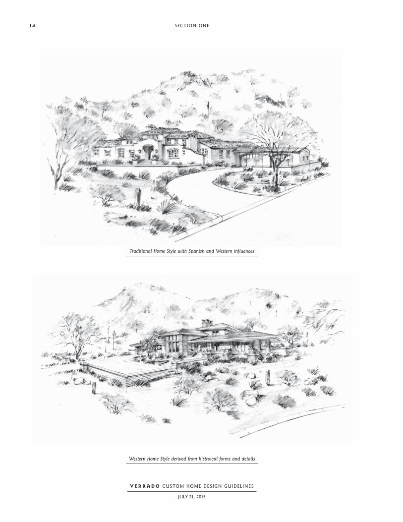
Traditional Home Style with Spanish and Western infl uences
Western Home Style derived from histroical forms and details

1.7DESIGN PHILOSOPHY AND INTRODUCTION
V E R R A D O CUSTOM HOME DESIGN GUIDEL INES
JULY 21, 2015
The intent of the design criteria is to avoid “stage-front” architecture. The massing of the buildings
as well as the application of details and overall character of the architectural Styles should be as au-
thentic as possible. For concept and inspiration, we have turned to the Desert Southwest’s own ar-
chitectural past. The Southwestern architectural lineage includes Western Regional, Territorial, and
Spanish-influenced Styles found throughout Arizona and the surrounding region. Designers and Ar-
chitects should rely on historical references and conceptual illustrations in these Design Guidelines
for inspiration. The application of Styles is further defined in the Architectural Styles section of this
document (Section Five).
CraftsmanshipAs a Community goal, each Custom Home in Verrado is expected to be designed in an artful man-
ner for the specific site opportunities each Lot has to offer, and be built with superior craftsmanship.
Rather than focusing on size, Verrado architecture focuses on authenticity, detail, and setting on the
land in a naturalistic manner. In the spirit of the great Home properties around the world, our high-
est aspiration is to offer more thoughtful floor plans, simplicity in massing, finer detailing, richer
finishes, and enduring quality.
Architectural Style Selection by Site Opportunities, Constraints, and LifestyleEach architectural Style offers uniquely distinct characteristics that respond differently to specific
site opportunities and constraints. Some Styles are best suited to longer street exposures, and may
not be compatible with narrower Lot shapes. Additionally, some Styles present a more formal axial
emphasis at the front of the Home, whereas others are purposely less formal and offer a casual qual-
ity. Styles indicative of less formal character and form are well suited for sloping Lots with steeper,
sometimes complex, grades. Home Styles with formal emphasis should be considered only for flat-
ter Lots of minimum slope. Every Home Site within Verrado possesses unique conditions and op-
portunities to contribute to the enhancement of Community quality in many ways.
1.2.6 Design IntegrityEach residential design may comply with all technical requirements, and yet not be visually pleasing
in terms of architectural composition or Design Integrity. The Design Review Committee will eval-
uate each Home design using these Elements of Composition, and if, in the opinion of the Design
Review Committee, the spirit of these guidelines have been met while some technical aspects may
not have been, a “variance for excellence” can be granted at the sole discretion of the Design Review
Committee. Design Integrity will be reviewed for each design submission according to the follow-
ing twelve (12) Elements of Composition.
1.8 SECTION ONE
V E R R A D O CUSTOM HOME DESIGN GUIDEL INES
JULY 21, 2015
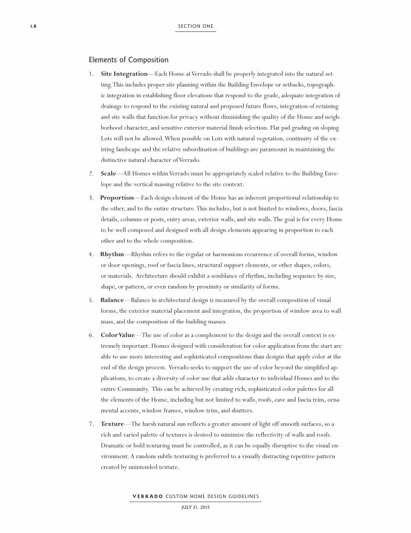
Elements of Composition
1. Site Integration—Each Home at Verrado shall be properly integrated into the natural set-
ting. This includes proper site planning within the Building Envelope or setbacks, topograph-
ic integration in establishing floor elevations that respond to the grade, adequate integration of
drainage to respond to the existing natural and proposed future flows, integration of retaining
and site walls that function for privacy without diminishing the quality of the Home and neigh-
borhood character, and sensitive exterior material finish selection. Flat pad grading on sloping
Lots will not be allowed. When possible on Lots with natural vegetation, continuity of the ex-
isting landscape and the relative subordination of buildings are paramount in maintaining the
distinctive natural character of Verrado.
2. Scale—All Homes within Verrado must be appropriately scaled relative to the Building Enve-
lope and the vertical massing relative to the site context.
3. Proportion—Each design element of the Home has an inherent proportional relationship to
the other, and to the entire structure. This includes, but is not limited to windows, doors, fascia
details, columns or posts, entry areas, exterior walls, and site walls. The goal is for every Home
to be well composed and designed with all design elements appearing in proportion to each
other and to the whole composition.
4. Rhythm—Rhythm refers to the regular or harmonious recurrence of overall forms, window
or door openings, roof or fascia lines, structural support elements, or other shapes, colors,
or materials. Architecture should exhibit a semblance of rhythm, including sequence by size,
shape, or pattern, or even random by proximity or similarity of forms.
5. Balance—Balance in architectural design is measured by the overall composition of visual
forms, the exterior material placement and integration, the proportion of window area to wall
mass, and the composition of the building masses.
6. Color Value—The use of color as a complement to the design and the overall context is ex-
tremely important. Homes designed with consideration for color application from the start are
able to use more interesting and sophisticated compositions than designs that apply color at the
end of the design process. Verrado seeks to support the use of color beyond the simplified ap-
plications, to create a diversity of color use that adds character to individual Homes and to the
entire Community. This can be achieved by creating rich, sophisticated color palettes for all
the elements of the Home, including but not limited to walls, roofs, eave and fascia trim, orna-
mental accents, window frames, window trim, and shutters.
7. Texture—The harsh natural sun reflects a greater amount of light off smooth surfaces, so a
rich and varied palette of textures is desired to minimize the reflectivity of walls and roofs.
Dramatic or bold texturing must be controlled, as it can be equally disruptive to the visual en-
vironment. A random subtle texturing is preferred to a visually distracting repetitive pattern
created by unintended texture.

1.9DESIGN PHILOSOPHY AND INTRODUCTION
V E R R A D O CUSTOM HOME DESIGN GUIDEL INES
JULY 21, 2015
8. Shade/Shadow—A vital component of design is the use of depth in architectural design and
detailing to compensate for the harsh natural sun. Without attention to this element of design,
a Home may be incompatible with the natural context. A series of transitional spaces or archi-
tectural features, such as an arcade, a trellis, or arbors from the outside to the inside is a nec-
essary component augmenting the visual appeal and livability of the Home. Also, depth in each
window or door opening adds value to the perceived quality of the Home.
9. Integrity/Visual Strength—The overall integrity of a design is measured in its visu-
al strength or in how well all the components look and feel when assembled together. A well-
composed Home that has excelled in all design elements listed here will have great visual
strength.
10. Material Integration—The Design Guidelines stipulate specific criteria regarding the al-
lowable type and placement of exterior materials. The purpose of this element as part of De-
sign Integrity is to ensure that in addition to providing the correct type and amount, artfulness
in overall composition is also achieved. The combination of textures shall be complementary
rather than competing. Colors shall be compatible and their placement must enhance the other
elements of Design Integrity such as balance, appropriateness, and visual strength.
11. Appropriateness—The degree of diversity of individual design expression will be measured
against the stated goals for the overall character of Verrado. Some individual designs may be
deemed inappropriate or incompatible with the goals for Verrado, and are not necessarily a re-
flection of the quality of the design. All Home designs shall be responsive to the climate and
the existing natural setting. Appropriateness also applies to all other elements listed here with
regard to the components being compatible in scale, material, color selection, and so on.
12. Artistic Endeavor—This element recognizes that the criteria presented in these Design
Guidelines are not intended to inhibit the overall artistic quality of a design submission. A de-
sign submission may be considered exempt from particular criteria if the design successfully
incorporates all other elements contained herein. The exception must not cause an undue nega-
tive impact to another individual property or the Community as a whole.
Western Farmhouse Home Style in the Golf District

SECTION T WO:
Site Design

2.2 SECTION T WO
V E R R A D O CUSTOM HOME DESIGN GUIDEL INES
JULY 21, 2015
Verrado Custom Home on a Natural Foothill Lot

2.3SITE DESIGN
V E R R A D O CUSTOM HOME DESIGN GUIDEL INES
JULY 21, 2015
2.1 The Home SiteThe creation of a memorable Home with high quality interior and exterior spaces requires great ar-
chitecture, a well-crafted landscape set comfortably in a desert environment, and a skilled approach
to site planning that accentuates the Home in an artful manner. The architecture of Verrado will
create a statement appropriate in scale and with simplicity of form. The landscaped Yard outside
the Home will accent the presence of the house by framing it in a combination of well-defined out-
door rooms and naturalized landscape spaces. Design of the Home Site should receive the same lev-
el of consideration as the design of structures. The outdoor spaces frame the Home and enhance the
character of the outdoor living environment. It is appropriate to create transition landscapes that
blend garden spaces and outdoor rooms into the native landscape beyond the Building Envelopes of
the property.
2.2 General Site Design ConsiderationsEach Home Site has unique landform and vegetation characteristics that serve as opportunities to
create well-designed exterior spaces that complement the house design and contribute to the am-
biance of the living experience. The Architect and Landscape Architect for each Home should be
experienced in designing Homes in desert-specific topography and must guide the Homeowner
through the process of locating the Home and outdoor spaces in a complementary manner to con-
tribute to the livability of the Home and overall context of the site. For Homes on Lots with high
visibility, or along streets with a number of Homes in view, the integration of each residential com-
position in the context of the entire Community is critical, as there are views to and from each
Home Site from many directions.
2.2.1 Lot Exhibits for Individual LotsLot Exhibits define unique conditions and requirements for each Lot. Criteria such as existing land
use designation, topography, native vegetation, easements, building height limitations, vehicular ac-
cess, or special landscape considerations may exist on a Lot. For this reason it is necessary to consult
the Lot’s specific Lot Exhibit prior to the start of design.

2.4 SECTION T WO
V E R R A D O CUSTOM HOME DESIGN GUIDEL INES
JULY 21, 2015
2.2.2 Lot Types and Relationship to Landform and Lot SizeWithin the Custom Home neighborhoods, there are four (4) distinctly different Lot types:
Natural Foothill Lots
Graded Foothill Lots
Town Lots
Park Lots
Lot types will vary by the amount of slope in natural terrain and by Lot size. The differences in Lot
slope and Lot size will have a significant influence on the individual site planning and architectural
design strategies.
Natural Foothill LotsThe majority of Lots in the Foothill District are situated on sloping landforms, and average approx-
imately one (1) acre in size. These large Lots are characterized by elevated and more rugged moun-
tain slopes, and some may be situated along the Golf Course. Native vegetation and drainage washes
remain in their natural condition. Homes located in the Natural Foothill Lots have great external
views to the mountains, Golf Course, city lights, and Verrado’s Main Street District. Some Natural
Foothill Lots have special design criteria developed specifically for the unique character of the Lot.
Refer to Appendix C in these Design Guidelines.
Graded Foothill LotsSome Lots in the Foothill District have been graded for development purposes. Some Lots are locat-
ed along Lost Creek and some near Verrado Way, and some may be situated along the Golf Course.
As a fully graded lot, cleared of existing vegetation, Graded Foothill Lots offer maximum flexibility
for site planning strategies within a predetermined Building Envelope. Homes located in the Grad-
ed Foothill Lots have great external views to the mountains, Golf Course, and Verrado’s Main Street
District.

2.5SITE DESIGN
V E R R A D O CUSTOM HOME DESIGN GUIDEL INES
JULY 21, 2015
Town LotsAll of the Custom Lots in the Golf District, and some of the Lots in the Town District, have been
graded to accommodate Homes with either single floor levels or multiple levels; these Lots range
in size, averaging approximately one-half (1/2) acre to one (1) acre and are considered Town Lots.
Town Lots are situated at the base of the foothills, and some will be in close proximity to the Golf
Course. As a fully graded lot, cleared of existing vegetation, Town Lots offer maximum flexibility
for site planning strategies within established setbacks. Homes located in the Town Lots have great
external views to the mountains and city lights, and some will have great external views to the Golf
Course. Some Town Lots have special design criteria developed specifically for the unique character
of the Lot. Refer to Appendix B and Appendix C in these Design Guidelines.
Park LotsSome of the Custom Lots in the Town District have been graded to accommodate Homes with ei-
ther single floor levels or multiple levels and are situated adjacent to a formative park; these Lots
range in size from approximately one-half (1/2) acre to one (1) acre and are considered Park Lots.
These Lots are situated at the base of the foothills, in close proximity to parks and natural open
space. As a fully graded Lot, cleared of existing vegetation, Park Lots offer maximum flexibility for
site planning strategies within established setbacks.
Two-story Home on Golf Course edge on graded Town Lot

2.6 SECTION T WO
V E R R A D O CUSTOM HOME DESIGN GUIDEL INES
JULY 21, 2015
Foothill District
Golf District
TownDistrict
NaturalFoothill
Lot
GradedFoothill
Lot
SpecialDesignCriteria
BuildingPadsApply
BuildingEnvelopes
Apply
GolfCourse
LotsTownLot
ParkLot
SignatureLot
X - denotes that condi-tion and/or designation may apply
LOT TYPE AND CONDITIONS
DISTRICTS LOT TYPE SPECIAL CRITERIA
Verrado Phase 1 and Phase 2 Lot type chart
PARCEL 5.701
Lots 101-112 X X X X
PARCEL 5.802
Lot 201 X X X X X
Lots 202-206 X X X X
Lot 207 X X X X X
Lots 208-213 X X X X
Lots 214-215 X X X X X
Lots 216-224 X X X X
Lots 225-239 X X X
Lots 240-241 X X X X
Lots 242-245 X X X
PARCEL 5.803
Lot 301 X X X X
Lots 302-305 X X X X
Lot 306 X X X
Lot 307 X X X
Lots 308-311 X X X X
Lots 312-313 X X X
Lots 314-319 X X X X
Lot 320 X X X X X
Lots 321-322 X X X X
Lots 323-325 X X X X
PARCEL 5.804
Lots 401-402 X X X X
Lot 403 X X X X X
Lots 404-414 X X X
Lot 415 X X X
Lots 416-418 X X X X
Lots 419-431 X X X
Lot 432 X X X X
Lots 433-436 X X X X X X

2.7SITE DESIGN
V E R R A D O CUSTOM HOME DESIGN GUIDEL INES
JULY 21, 2015
Foothill District
Golf District
TownDistrict
NaturalFoothill
Lot
GradedFoothill
Lot
SpecialDesignCriteria
BuildingPadsApply
BuildingEnvelopes
Apply
GolfCourse
LotsTownLot
ParkLot
SignatureLot
X - denotes that condi-tion and/or designation may apply
LOT TYPE AND CONDITIONS
DISTRICTS LOT TYPE SPECIAL CRITERIA
Verrado Phase 1 and Phase 2 Lot type chart
PARCEL 3.101
Lots 1-18 X X X
Lots 19-20 X X X X
Lot 21 X X X X
Lots 22-31 X X X
Lot 32 X X X X
Lot 33 X X X X X
Lots 34-42 X X X
Lots 43-44 X X X
Lots 45-47 X X X
Lots 48-50 X X X X
Lot 51 X X X X X
Lots 52-54 X X X
Lots 55-56 X X X X
Lots 57-60 X X X
Lots 61-63 X X X X
Lots 64-66 X X X
Lot 67 X X X X
Lots 68-69 X X X X X
Lot 70 X X X X
Lots 71-77 X X X
Lots 78-79 X X X X
Lots 80-83 X X X X X
Lots 84-85 X X X X
Lots 86-100 X X X
Lots 101-102 X X X X
Lot 103 X X X
Lots 104-105 X X X X

2.8 SECTION T WO
V E R R A D O CUSTOM HOME DESIGN GUIDEL INES
JULY 21, 2015
Verrado Phase 1 and Phase 2 Custom Home Lot types
FOOTHILL DISTRICT
GOLF DISTRICT
LEGENDNF NATURAL FOOTHILL LOT GF GRADED FOOTHILL LOT TOWN LOT
NF
NF
NF
NF
GFGF
TL
PARCEL 5.802
PARCEL 5.803
PARCEL 5.804
TL
TL
TLTL
TL
GF
GFNF
GF
NF
NF
NF
NF
NF
NF
NF
NF
GF
GF
GF
PL
TL
PL
RETENTION BASIN
RETENTION BASIN
MAIN STREET DISTRICT
PARCEL 3.101
VERR
AD
O W
AYTOWN DISTRICT
PHASE 2NEIGHBORHOODS
PHASE 1
CUSTOM HOMES
PL PARK LOT
TL
TL
TL
PLPLPL
PL
PL
PLPL
NF
PHASE 2
CUSTOM HOMES
GFGF
For illustrative purposes only
FOOTHILL DISTRICT
PARCEL 5.701
TL

2.9SITE DESIGN
V E R R A D O CUSTOM HOME DESIGN GUIDEL INES
JULY 21, 2015
2.2.3 Homes Built on Golf Course LotsGolf Course Lots differ from the other types of Lots in that they must have two facades of front el-
evation quality: one that faces the main street and one that faces the Golf Course. Although all
Homes in Verrado are required to treat all exterior facades equally, the artfulness of the elevation facing
the Golf Course must be carefully considered. The following strategies shall be used when designing
Homes that can be viewed from the Golf Course:
Provide strong massing composition and detailing for all sides of the Home.
Consider enhancing the building elevation facing the Golf Course by placing vertical accents in
strategic locations Visible from the Golf Course.
Design a strong sense of proportion and balance for all sides.
Utilize artfulness in the site wall design, combining view fence and solid walls. Site walls that
do not integrate into the character, layout, and appearance of the architectural design will not
be approved.
Integrate a well-conceived color and material palette.
Select outdoor furnishings compatible with the design of the Home.
Provide a well-integrated landscape design.
View from porch overlooking park in Park Lots

2.10 SECTION T WO
V E R R A D O CUSTOM HOME DESIGN GUIDEL INES
JULY 21, 2015
Design Considerations for Golfing ActivitiesAs with all Golf Course Lots, there is an inherent risk that golf balls and the play of golf may impact
a Lot or Home. Detailed consideration shall be given during the site planning of a Golf Course Lot
to the possibility of errant golf balls, particularly with the orientation of windows or other break-
able surfaces of the Home.
No form of protective netting, screens, excessive landscaping, fences, or large blank walls will be
allowed along, or within view of, the Golf Course.
Proper determination of structure location, orientation, massing, and setbacks should provide
for maximum view orientation with minimal adverse impact from the play of golf.
Design consideration should be given to the noise and activity generated by golfers, the golf club,
and the golf maintenance operations.
Approval of Final Design Submission by the Design Review Committee does not constitute as-
surance of protection from errant golf balls.
Considering Views from the Golf CourseThe views from the Golf Course shall be considered, even for Lots not directly on the Golf Course
perimeter. All of the design strategies indicated for Golf Course Lots shall be considered when de-
signing Homes that may be located just off the Golf Course perimeter. The Golf Course experience
should improve over time as more Homes are added to the visual composition.
2.2.4 Signature LotsA number of select Lots have been designated as Signature Lots. Signature Lots have particular sig-
nificance in the Community due to their prominence as either a Lot on an axial focus with a street
alignment, a focal Golf Course Lot, a significant corner Lot expanse, or a prominent hillside Lot.
Two-story massing facing Golf Course with well-articulated exterior elevation

2.11SITE DESIGN
V E R R A D O CUSTOM HOME DESIGN GUIDEL INES
JULY 21, 2015
The design professionals working on these Lots are encouraged to celebrate their special location
and respond accordingly in the design. The design response may utilize one of the following strate-
gies:
Provide vertical emphasis in the building massing on the axial alignment.
Provide special landscape features in the form of large, specimen trees and/or accent planting.
Provide special design consideration for prominence of significant landform.
Location of designated Signature Lots in Custom Home neighborhoods
FOOTHILL DISTRICT
GOLF DISTRICT
SSS
SS
S
SS
S
S
SS
SS
LEGENDS DESIGNATED SIGNATURE LOT
SS
SS
PARCEL 5.802
PARCEL 5.803
PARCEL 5.804
S
SS
S
SS
S
S
S
S
S
PARCEL 3.101
TOWN DISTRICT
PHASE 2
NEIGHBORHOODS
VERR
AD
O W
AY
PHASE 1
CUSTOM LOTS
MAIN STREET DISTRICT
PHASE 2
CUSTOM LOTS
FOOTHILL DISTRICT
For illustrative purposes only
PARCEL 5.701

2.12 SECTION T WO
V E R R A D O CUSTOM HOME DESIGN GUIDEL INES
JULY 21, 2015
2.2.5 Selecting a Home Site on Sloping or Level LandformsIn Verrado, each prospective resident has the opportunity to select a Home Site that provides the
potential for a Home design, that meets the Homeowner’s expectations for Style and exterior expe-
rience. Some Lots offer sloping terrain and naturally undulating landforms punctuated with stands
of native vegetation, which present opportunities for building Homes with spectacular views
and/or added privacy. Other Lots occur on gently sloping or level landforms. There are distinct
challenges among the two differing landforms contained in Verrado that influence individual site
planning, Style selections, and architectural design strategies.
Prospective Buyers are strongly encouraged to consider their expectations for living environment,
desired level of privacy, and construction budgets when making a decision to purchase a Lot on ei-
ther a sloping landform or a level grade. Construction of Homes designed for sloping Lots will
require the Homeowner and Architect to pursue design solutions to minimize the amount of grad-
ing and site disturbance to improve site integration. Design solutions can include the use of retain-
ing walls, terraced floor levels, and selection of a less formal architectural Style. In general, Homes
built on sloping Lots will cost more per square foot of construction than Homes built on level Lots.
Homes designed with large, single-level floor areas that work against the contours and require ex-
cessive Cut and Fill will not be allowed on Lots with sloping landforms.
Custom Home with distinctive street presence on Graded Golf District Lot

2.13SITE DESIGN
V E R R A D O CUSTOM HOME DESIGN GUIDEL INES
JULY 21, 2015
2.2.6 Visual Openness and Relationship to the StreetIn addition to landform characteristics, each Home in Verrado will have its site design influenced by
the natural openness specific for each Lot. The amount of visual openness as viewed to and from the
Lot from the street, neighboring Lots, and/or the Golf Course, or from the rest of the Communi-
ty, must be considered when developing site planning strategies and architectural elevations. His-
torically, residential streets with memorable character rely on the strong visual relationships of the
Homes to the street, without compromising desired levels of privacy. Within neighborhoods of high
levels of openness and forward-facing entries, it is important to orient the main Home entry to the
street and allow transparency in the front yard landscape to reinforce the relationship of the Home
to the street. On corner Lots where the Home has two street frontages, and driveway access is not
provided on the primary street, it is important to provide a strong street presence on the primary
street.
2.2.7 Driveway Access and Design ConsiderationsDriveway entries play a significant role in creating the street appeal in Verrado, and, when designed
to take advantage of the natural features of the site, will contribute to the overall composition of the
Home. Resident driveways and guest arrival opportunities are determined by the Architect after a
complete site analysis, and are submitted for review and approval to the Design Review Committee.
All corner Lots and mid-street Lots will have one (1) access point for a resident, guest, and/or ser-
vice driveway.
2.2.8 Multiple Lot Joining Throughout Verrado there are opportunities to purchase two (2) or three (3) individual and adjoin-
ing Lots, and combine them into one (1) larger Lot. Multiple Lot Joins are allowed in the areas of
Natural Foothill and Graded Foothill Lots in Parcels 5.803, 5.804, and 3.101 only. Multiple Lot
Joins are not allowed in Town and Park Lots in Parcels 5.802 and 3.101.
Multiple Lot JoiningWhen applicable, two (2) or three (3) adjoining Lots may be considered for combining into a Mul-
tiple Lot Join. In the event that a Prospective Buyer, or Lot Owner, wants to purchase two (2) or
three (3) contiguous Lots and combine those Lots into one Home Site, he or she must receive ap-
proval from the Design Review Committee to confirm that those Lots are possible to assemble. Pri-
or to Design Review Committee submission, the Prospective Buyer or Lot Owner shall submit a
proposed reconfiguration of the Building Envelope to the Design Review Committee, which will re-
view and approve, or disapprove, the reconfiguration at its sole and absolute discretion.

2.14 SECTION T WO
V E R R A D O CUSTOM HOME DESIGN GUIDEL INES
JULY 21, 2015
Approval of the reconfigured Building Envelope must be obtained prior to preparing the Prelimi-
nary Design Submittal. A reconfigured Building Envelope may span the common Lot line, or have a
connection between the two prior Building Envelopes, as long as the combined total area of the new
Building Envelope does not exceed seventy-five (75) percent of the sum of the two (2) or three (3)
individual original Building Envelopes.
On Lots located on hillsides, it is more likely that reconfiguration of the Building Envelope on more
than one Lot may cause an adverse effect on Adjacent Lots. The Design Review Committee will give
consideration at its sole discretion to the Adjacent Lots with any proposed reconfiguration. Any con-
sideration of Building Envelope reconfiguration, including determination of driveway access, will be
based on, but not limited to, the following guidelines:
Location of existing natural drainage washes and proposed drainage patterns
Location, density, and quality of vegetation
Topography, slope, and viewshed constraints
Existing natural features.
Existing or planned driveways on Adjacent Lots
2.2.9 Lots with Special Design Criteria For some Homes, a combination of general design guidelines and Lot-specific special design criteria
have been established. Lot-specific special design criteria are located in Appendix B and Appendix
C of this document. It is the expressed responsibility of the Homeowner and his or her design team
to identify the accurate Lot type and determine if special design criteria apply. Refer to the adjacent
map for designation of Lots with special criteria.
In the event that a conflict arises between the general Design Guidelines in this book and the spe-
cial design criteria in Appendix B and Appendix C, the information in Appendixes B and C will gov-
ern as final.

2.15SITE DESIGN
V E R R A D O CUSTOM HOME DESIGN GUIDEL INES
JULY 21, 2015
Lots with Lot-specific Special Design Criteria
FOOTHILL DISTRICT
GOLF DISTRICT
LEGENDSC LOT WITH DESIGNATED SPECIAL DESIGN CRITERIA (REFERENCE APPENDIXES B AND C)
PARCEL 5.802
PARCEL 5.803
PARCEL 5.804
SC
SCSC
SC
SC
SC
SCSC
SC
SC
PARCEL 3.101
TOWN DISTRICT
PHASE 2
NEIGHBORHOODS
VERR
AD
O W
AY
PHASE 1
CUSTOM LOTS
MAIN STREET DISTRICT
SCSC
SC
SC
SC
SCSC
SCSC
SC SC SC
SCSCSCSC
SC
SCSC
SC
SC
SCSC
PHASE 2
CUSTOM LOTS
FOOTHILL DISTRICT
For illustrative purposes only

2.16 SECTION T WO
V E R R A D O CUSTOM HOME DESIGN GUIDEL INES
JULY 21, 2015
2.3 Composing Elements within a Site Plan—Natural Foothill and Graded Foothill Lots (Parcels 3.101, 5.803 and 5.804)
For Homes built on a Natural Foothill Lot or Graded Foothill Lot, predetermined Building Enve-
lopes have been established, as shown in the Lot Exhibit. Each structure that forms the complete
composition must be contained within the Building Envelope and contribute meaningfully to the
overall composition for the site upon which it is situated. The placement of each component adja-
cent to the main Home, including, but not limited to, trellises/arcades/arbors, ramadas/gazebos,
and accessory structures (Guest Houses, studios, offices) or walls, must be sited in a manner coher-
ent to the principles of design for that specific Home.
2.3.1 Designing within the Building EnvelopesThe Design Guidelines for Verrado place a high value on the character of undisturbed natural vege-
tation in each neighborhood, affording each Home the opportunity to achieve privacy from Lot to
Lot. Determining where each house can be located on the property to maintain the overall charac-
ter of the open space is achieved by establishing Building Envelopes. It is the intent of these Design
Guidelines to provide the Architect with flexible options in site planning and Home design without
diminishing the quality of on-site natural features or off-site view potential.
In Verrado, a significant amount of analysis and thought has been given to determine the location
and spatial size of Building Envelopes. These Building Envelopes have been carefully selected to
maximize the value of the individual Lot and preserve the quality of Adjacent Lots. Any request to
modify the established Building Envelopes is discouraged. In cases of special circumstances, the De-
sign Review Committee may consider a request for modification to a Building Envelope. Written
approval from the Design Review Committee is required before final design begins.

2.17SITE DESIGN
V E R R A D O CUSTOM HOME DESIGN GUIDEL INES
JULY 21, 2015
2.3.2 Building EnvelopesEach Home Site has a specific Building Envelope defining the buildable area of the Lot in which all
Improvements are required to be placed. All construction, including the Home, Guest House, pools
and pool houses, Accessory Buildings, garages, patios, site and retaining walls, vehicular access, auto
courts, and landscape improvements, must be built within the limits of the Building Envelope. All
construction activities, including equipment maneuvering and material storage, are limited to this
area. The Design Review Committee must approve removal of any trees or protected plants, where
removal is required for the reasonable development of the Lot. The Building Envelope for each spe-
cific Lot is depicted on the Lot Exhibit for each subdivision.
The Building Envelope acts as a limit beyond which no construction activity, including grading, ma-
terial storage, and access, may take place. All construction improvements must be held to a mini-
mum of five (5) feet within the Building Envelope to allow for construction activity to be contained
within the Building Envelope.
Building Envelope and envelope setback diagram—Graded Foothill Lot
Landscape Improvements completely within Building Envelope
Homeowner responsible for native landscape restoration outside of Building Envelope to property line and/or curb
Property line
Limit of Building Envelope
GO
LF C
OU
RSE
25’ minimum building setback on Golf Course edges
20’ minimum building setback on side and rear yards
40’ Front Yard Building Setback
Designated Public Utility Eastment (P.U.E.)
Driveway

2.18 SECTION T WO
V E R R A D O CUSTOM HOME DESIGN GUIDEL INES
JULY 21, 2015
Building Envelope and envelope setback diagram—Natural Foothill Lot
Property line
Limit of Building Envelope
25’ minimum building setback on Golf Course edges
Natural drainage feature
Golf Course
Driveway
Stre
et
20’ minimum building setback on side and rear yards of each Lot
Designated public utility easement (PUE)
40’ Front Yard Building Setback
Landscape Improvements completely within Building Envelope areas not disturbed by construction can remain natural
Designated open space to remain natural and undisturbed

2.19SITE DESIGN
V E R R A D O CUSTOM HOME DESIGN GUIDEL INES
JULY 21, 2015
2.3.3 Modifications to the Building EnvelopeRequests to modify the shape and position of the Building Envelope may be considered by the De-
sign Review Committee at its sole discretion. Any request to expand the total size of the Building
Envelope is strongly discouraged, and approval will be granted only in the event of special circum-
stances, in the opinion of the Design Review Committee. No modification of the Building Envelope
is allowed unless specifically approved in writing by the Design Review Committee. All consid-
erations of Building Envelope reconfigurations, including approval of driveway access, will be re-
viewed based on impact to the street scene; the location of existing natural and proposed drainage
washes; location, density, and quality of vegetation; and existing or planned driveways on Adjacent
Lots.
Minor Modifications to the Building EnvelopeSome Minor Modifications to the Building Envelope may be allowed by the Design Review Com-
mittee upon a Homeowner’s application for this specific variance. Minor Modifications to the Build-
ing Envelope may be approved when justified in the Design Review Committee’s opinion, based on
consideration of views, privacy, location of existing Improvements, topography, natural features,
existing vegetation, drainage corridors, and the overall character of the Community. Minor Modi-
fications will be considered with a Preliminary Design Submittal and will not require separate sub-
mission. Although Minor Modifications will be considered, the Design Review Committee has no
obligation to approve such proposed modifications for any reason.
Minor Modifications shall be defined as changes to the established Building Envelope of less than ten
(10) feet in any outward direction beyond the original Building Envelope, as shown on the Lot Ex-
hibit. Relocation of the Building Envelope to accommodate a driveway will be considered minor
unless, in the opinion of the Design Review Committee, the modification in driveway location ma-
terially impacts the views, privacy, and/or character of an Adjacent Lot, streets, or other Common
Areas. Under no circumstances can the Minor Modification of a Building Envelope result in the in-
crease of total area of Building Envelope when compared to the numeric amount represented on a
Lot Exhibit, unless otherwise approved by the Design Review Committee.

2.20 SECTION T WO
V E R R A D O CUSTOM HOME DESIGN GUIDEL INES
JULY 21, 2015
Major Modifications to the Building EnvelopeA Major Modification to a Building Envelope shall be defined as any proposed modification that ex-
ceeds ten (10) feet in any outward direction beyond the original Building Envelope, as shown on the
Lot Exhibit. Major Modification to a Building Envelope will require written approval of all Own-
ers of Adjacent Lots on a form provided by the Design Review Committee. In the case where the
Adjacent Lots are owned by the Developer, written approval from the Developer will be required.
It is the sole responsibility of the Homeowner to obtain written approval from all Owners of Adja-
cent Lots prior to submission of the request for Major Modification. Under no circumstances can
the Major Modification of a Building Envelope result in the increase of total area of the Building En-
velope when compared to the numeric amount represented on a Lot Exhibit, unless otherwise ap-
proved by the Design Review Committee.
Modifications along the Golf CourseBuilding Envelopes on Lots adjacent to Golf Course property have been established to maintain a
discrete distance between Homes and the Golf Course. Building Envelopes on Golf Course Lots are
considered fixed along the Golf Course edge. Proposed Building Envelope modifications that would
result in a reduction of distance between the Golf Course and Building Envelopes will not be con-
sidered.
Separation of Building Envelopes between Adjacent LotsAppropriate separation between Building Envelopes has been established to enhance levels of priva-
cy between Adjacent Lots. In most cases, Building Envelopes are separated at a distance of forty (40)
feet or more from the envelope limits on Adjacent Lots. Requests for modification of Building En-
velopes that would reduce separation to a distance of less than twenty (20) feet from the property
line will not be considered. In those cases where the original Building Envelope has been established
at less than twenty (20) feet of separation from a property line, no adjustment will be approved that
would further reduce separation from the Adjacent Lot, or allow areas currently greater than the
minimum distance to be reduced to the minimum. A Lot Owner will not be required to alter an ap-
proved Building Envelope because of a modification approved by the Design Review Committee on
an Adjacent Lot.

2.21SITE DESIGN
V E R R A D O CUSTOM HOME DESIGN GUIDEL INES
JULY 21, 2015
2.3.4 Established Minimum Building SetbacksCustom Home Lots will have established Building Envelopes, and will also have minimum building
setbacks along the front yard, and along front yards and side yards along streets on corner Lot con-
ditions. The established Building Envelope and building setbacks will be identified on Lot Exhibits,
and, if more restrictive than the Town jurisdiction for current zoning, the established Building En-
velope and building setbacks will take precedence. These building setbacks will apply in addition to
the limits of the Building Envelope. Lots may have minimum setbacks established by these guide-
lines that may be greater than those established in the Verrado Community Master Plan or by the
Town of Buckeye. On corner Lots, selection of which street frontage is designated as front yard is
determined by the Homeowner and design team.
Composing site elements to minimize grading and maintain
or re-establish native landscape
Enhanced privacy with minimum building separation
Native landscape to remain or be revegetated
Garage area screened from main street

2.22 SECTION T WO
V E R R A D O CUSTOM HOME DESIGN GUIDEL INES
JULY 21, 2015
Front Yard Building Setbacks Front Yard Building Setbacks are measured at forty (40) feet from the Lot property line along the
street. All buildings, including the main Home, Accessory Buildings, and garages, are to be locat-
ed beyond the forty (40) foot building setback. On corner Lots, selection of which street frontage is
designated as front yard is determined by the Homeowner and design team. Driveways, auto courts,
and patios are allowed within the Front Yard Building Setback, provided they are located within the
Building Envelope.
Within the Front Yard Building Setback, no Home, Accessory Building or garage, solid walls, or oth-
er Improvement higher than three (3) feet from the natural grade may be installed or constructed;
however, Improvements lower than three (3) feet from the natural grade may be constructed if lo-
cated within the Building Envelope.
Side Yard Building SetbacksBuilding setbacks for side yards adjacent to another Lot are predetermined and measured at twen-
ty (20) feet from the Lot property line along the street. Refer to the Lot Exhibit for specific build-
ing setbacks.
Side Yard Building Setbacks along Streets on Corner LotsBuilding setbacks for side yards abutting a street are measured at thirty (30) feet from Lot proper-
ty line along the street. Within the thirty (30) foot setback, all Front Yard Building Setback criteria
shall apply to side yard conditions along streets. All buildings, including the main Home, Accesso-
ry Buildings, and garages, are to be located beyond the thirty (30) foot building setback. Driveways,
auto courts, and patios are allowed within the side yard building setback, provided they are located
within the Building Envelope.
Rear Yard Building SetbacksBuilding setbacks for rear yards are measured at twenty-five (25) feet from the rear Lot property
line. Refer to the Lot Exhibit for specific building setbacks.
Golf Course Building SetbacksOn Lots adjacent to Golf Course property, building setbacks are fixed at twenty-five (25) feet, as
measured from each property line adjacent to a Golf Course edge. Walls, patios, pools, and fenc-
es can be located within the Golf Course building setback provided that they are within the Build-
ing Envelope.
Special Design Criteria for Natural Foothill and Graded Foothill LotsRefer to Appendix B and Appendix C for Lot-specific special design criteria that may supersede the
aforementioned building setbacks.

2.23SITE DESIGN
V E R R A D O CUSTOM HOME DESIGN GUIDEL INES
JULY 21, 2015
2.3.5 Designated Open SpaceEach Home Site has designated open space within each Lot (consult the Lot Exhibit for each specif-
ic Lot). Open space functions as a buffer between properties, preserves native vegetation and wash-
es, and creates visual connectivity within the larger desert context. The open space is defined as the
area of native restoration or undisturbed land outside of the Building Envelope. If open
space landscape is undisturbed, construction disturbances are not permitted, the landscape shall re-
main in its natural condition, and placement of any structure, landscape Improvements, or site al-
terations is prohibited.
2.4 Composing Elements within a Site Plan—Town Lots (Parcel 5.802 and Parcel 3.101)
For Homes built on Town Lots, building setbacks have been established for the front, sides, and
rear yards. Each building structure that forms the complete composition must be contained with-
in the building setbacks and contribute meaningfully to the overall composition for the site upon
which it is situated. Walls and fences can be located within the building setbacks. The placement of
each component adjacent to the main Home, including, but not limited to, trellises/arcades/arbors,
ramadas/gazebos, and accessory structures (Guest Houses, studios, offices) or walls, must be sited
in a manner coherent to the principles of design for that specific Home.
Signature Home on corner Lot in Town District

2.24 SECTION T WO
V E R R A D O CUSTOM HOME DESIGN GUIDEL INES
JULY 21, 2015
2.4.1 Designing within Setbacks and the Designated Building PadA significant amount of thought has been given to determine the depth of building setbacks, and the
resulting separation of Homes on the Town Lots. These building setbacks have been carefully mea-
sured to maximize the value of the individual Lot and preserve the quality of Adjacent Lots. Any re-
quest to modify the established building setbacks will not be considered.
All Town Lots have a designated Building Pad as delineated on the Lot Exhibit for Parcel 5.802 and
Parcel 3.101. Building Pads have been engineered and constructed to accommodate building. Areas
outside of the designated Building Pad, which are often sloping, are not intended nor designed for
building structures, but may be used for patios, pools, walls, fences, landscape, and retaining walls.
Any structures located within the building setbacks, but beyond the limits of the designated Build-
ing Pad, may require additional geotechnical analysis and earthwork construction by the Owner to
accommodate them in this area.
2.4.2 SetbacksEach Home Site has specific minimum building setbacks that may or may not correspond to the des-
ignated Building Pad. Construction of all buildings, including the Home, Guest House, pool houses,
Accessory Buildings, and garages, must be built within the limits of the building setbacks. In addi-
tion, the Homeowner is required to make all landscape Improvements, including patios, pools, site
and retaining walls, vehicular access, auto courts, and landscape plantings, for the entire Lot within
the limits of the property lines.
Front Yard Building Setbacks Front Yard Building Setbacks are measured at twenty-five (25) feet from the Lot property line along
the street. All buildings, including the main Home, Accessory Buildings, and garages, are to be lo-
cated beyond the twenty-five (25) foot setback. Driveways, auto courts, and patios are allowed
within the Front Yard Building Setback.
Within the Front Yard Building Setback, between the front Lot boundary and twenty-five (25) feet
from the front Lot boundary, no Home, Accessory Building or garage, solid walls, or other Im-
provement higher than three (3) feet from the natural grade may be installed or constructed; how-
ever, Improvements lower than three (3) feet from the natural grade may be constructed.
Side Yard Building Setbacks on Corner LotsBuilding setbacks for side yards abutting a street are measured at twenty-five (25) feet from the Lot
property line along the street. Within the twenty-five (25) foot setback, all Front Yard Building Set-
back criteria apply to side yard conditions along streets. All buildings, including the main Home,
Accessory Buildings, and garages, are to be located beyond the twenty-five (25) foot setback. Drive-
ways, auto courts, and patios are allowed within the side yard building setback.

2.25SITE DESIGN
V E R R A D O CUSTOM HOME DESIGN GUIDEL INES
JULY 21, 2015
Walls allowed on property lines in rear yard and side yards
Twenty-five (25) foot Front Yard Building Setback
Thirty (30) foot rear yard building setback along Golf Course or open space
Twenty-five (25) foot side yard building setback adjacent to street.
Seven (7) foot side yard building setback on one side only
Twenty-three (23) foot side yard building setback on one side only
Side Yard Building SetbacksBuilding setbacks for side yards adjacent to another Lot are predetermined and measured at either
twenty-three (23) feet on one side and seven (7) feet on the other side from Lot property line. Re-
fer to the Lot Exhibit for specific building setbacks and to understand the predetermined locations
for the specific side yard setbacks.
Rear Yard Building SetbacksBuilding setbacks for rear yards adjacent to another Lot, or along Golf Course property are mea-
sured at thirty (30) feet from rear Lot property line.
Setback diagrams on Town Lots

2.26 SECTION T WO
V E R R A D O CUSTOM HOME DESIGN GUIDEL INES
JULY 21, 2015
PARK
PHASE 2
NIEGHBORHOODS
Lot 76
Lot 77
Lot 34
Lot 81
Lot 80
Lot 79
Lot 78
Lot 33
Lot 32
Lot 85
Lot 84
Lot 83
Lot 82
Lot 91
Lot 92
Lot 31
Lot 30
Lot 86
Lot 33 Lot 77
2.5 Composing Elements within a Site Plan—Park Lots (Parcel 3.101)
In general, building setbacks have been established for the front, sides, and rear yards of Park Lots.
Each building structure that forms the complete composition must be contained within the build-
ing setbacks and contribute meaningfully to the overall composition for the site upon which it is sit-
uated. The placement of each component adjacent to the main Home, including, but not limited to,
trellises/arcades/arbors, ramadas/gazebos, and accessory structures (Guest Houses, studios, offic-
es) or walls, must be sited in a manner coherent to the principles of design for that specific Home.
Park Lots adjacent to Heritage Street

2.27SITE DESIGN
V E R R A D O CUSTOM HOME DESIGN GUIDEL INES
JULY 21, 2015
2.5.1 Homes Designed to Have a Positive Street PresenceHomes designed on Park Lots will take on a more formal appearance, and face the the street and
parks in a proud manner. In the tradition of classic neighborhood building, Homes on Park Lots will
be designed with an attention to site planning, grading, architectural, and landscape design details.
Park Lots adjacent to Canyon Drive
Lot 55
Lot 51
Lot 56 Lot 67 Lot 68
Lot 69Lot 70Lot 48Lot 49Lot 50
PARK
Lot 54 Lot 57 RETENTION AREA
VERR
AD
O W
AY
RETENTION AREA
Lot 71Lot 47
Lot 46Lot 45
Lot 43
Lot 42
Lot 40

2.28 SECTION T WO
V E R R A D O CUSTOM HOME DESIGN GUIDEL INES
JULY 21, 2015
Raised Building PadsSome Park Lots will have raised pads measuring two (2) to four (4) feet above the sidewalk eleva-
tion. For those Lots with raised pads, the front yard landscape will have special features that add
character and quality to the neighborhood. The special landscape features required include:
A walkway leading from the Home’s entry to the street in as straight a path as possible. The walk-
way should connect the street/sidewalk to the porch steps.
For grade transition, well-crafted stairs with low-scale cheek walls are required. Stairs can have
rectilinear walls or curved/splayed walls depending on the character of the Home.
For Homes with more than two (2) feet of grade difference from the sidewalk to the pad, a low
front yard retaining wall will be required. The low wall must be a maximum of two (2) feet
above the sidewalk and be placed a minimum of two (2) feet off the edge of the back of the side-
walk.
Low front yard retaining walls must have weep holes using a maximum two (2) inch diameter
pipe set at four (4) inches above finish grade as measured to the top of pipe, and spaced horizon-
tally as needed.
Front Porches in Town DistrictMost Homes on the Park Lots will have front porches. Some Lots will require front porches. Porch-
es should be designed to create usable outdoor living areas that add to the quality of the street envi-
ronment.
Front porches must be raised a minimum of twenty-four (24) inches above the finish grade.
On corner Lots, porches that wrap a front and side elevation can add to the quality of both
streets. Some Lots will have requirements for porches that wrap two sides.
Front porches must be sized a minimum of ten (10) feet deep by twenty-five (25) feet wide.
Porch railings and their details should be designed as extensions of the Home’s architectural
character. Porch railings with some transparency are recommended.
Driveways in Town DistrictIn addition to the driveway design guidelines stated throughout this section, the following shall ap-
ply to Park Lots:
All driveways must be no wider that twelve (12) feet at the curb, and cannot expand beyond
twelve (12) feet in width within eight (8) feet of the sidewalk or right-of-way.
Hollywood drives—driveways that include landscape strips in the center—are encouraged to re-
duce the amount of hardscape in the front yard area.
Driveway locations are prescribed on some Lots. Refer to Appendix C.
Trees installed within the Streetscape Zone are considered fixed in place. Locate driveways to
minimize impact to existing street trees.

2.29SITE DESIGN
V E R R A D O CUSTOM HOME DESIGN GUIDEL INES
JULY 21, 2015
Front-of-Home Orientation to Streets and ParksHomes designed adjacent to parks and entry streets will have their front-of-Home orientation de-
termined by special criteria in Appendix C.
In most cases, Homes are required to sit parallel to the Lot boundary on the primary street.
All Homes are required to have front entry doors that face the primary street.
Some Lots will be required to have two-story massing. Refer to Appendix C.
On corner Lots, Homes with two-story massing should be placed on the street side of the Lot.
Garages in Town DistrictIn addition to the garage design guidelines stated throughout this section, the following shall apply
to Park Lots:
Some Lots will have the location of side- and rear-loaded garages prescribed in Appendix C.
All front faces of garages must be no closer than fifteen (15) feet to front elevation of the Home.
2.5.2 Designing within Setbacks and a Designated Building PadA significant amount of thought has been given to determine the depth of building setbacks, and the
resulting separation of Homes on the Park Lots. These building setbacks have been carefully mea-
sured to maximize the value of the individual Lot and preserve the quality of Adjacent Lots. Any re-
quest to modify the established building setbacks will not be considered.
All Park Lots have a designated Building Pad as delineated on the Lot Exhibit for Parcel 3.101.
Building Pads have been engineered and constructed to accommodate building structures. Areas
outside of the designated Building Pad, which are often sloping, are not intended nor designed for
building structures, but may be used for patios, pools, walls, fences, landscape, and retaining walls.
Any structure located within the building setbacks, but beyond the limits of the designated Building
Pad, may require additional geotechnical analysis and earthwork construction by the Owner to ac-
commodate them in this area.
Building Setbacks for Park LotsEach Home Site has specific minimum building setbacks that may or may not correspond to the des-
ignated Building Pad. Construction of all structures, including the Home, Guest House, pool hous-
es, Accessory Buildings, and garages, must be built within the limits of the building setbacks. In
addition, the Homeowner is required to make all landscape Improvements, including patios, pools,
site and retaining walls, vehicular access, auto courts, and landscape plantings, for the entire Lot,
within the limits of the property lines.
For all Park Lots, refer to Appendix C for Lot-specific special design criteria including each Lot’s
building setbacks.

2.30 SECTION T WO
V E R R A D O CUSTOM HOME DESIGN GUIDEL INES
JULY 21, 2015
2.6 Composing Elements within a Site Plan—Town Lots (Parcel 5.701)
For Homes built on Town Lots in Parcel 5.701, building setbacks have been established for the
front, sides, and rear yards. Each building structure that forms the complete composition must be
contained within the building setbacks and contribute meaningfully to the overall composition for
the site upon which it is situated. Walls and fences can be located within the building setbacks. The
placement of each component adjacent to the main Home, including, but not limited to, trellis-
es/arcades/arbors, ramadas/gazebos, and accessory structures (Guest Houses, studios, offices) or
walls, must be sited in a manner coherent to the principles of design for that specific Home.
2.6.1 Homes Designed to Have a Positive Street PresenceHomes within Parcel 5.701 will take on a more formal appearance, and face the the street in
a proud manner. Homes in parcel 5.701will be designed with an attention to site planning,
grading, architectural composition, and landscape design details that result in a positive presence to
the street ans seen in traditional of historic neighborhoods.
Front-of-Home Orientation to the Street
The front face of the Home shall be parallel and perpindicular to the primary street.
In most cases, the Home will be required to be placed forward to the front building setback.
The front entry door shall face the street.
The front walkway shall extend from the front entry to the public sidewalk.
Front Porches and Front of House Living
Broad front porches that present an inviting face to the street are strongly encouraged.
Livable spaces and rooms that face the street are strongly encouraged.
Entry courtyards and architecturally significant entry building massing is encouraged on the
front elevation of the Home.
Garages Placement
The garage may not be the most visually dominant element of the front elevation of the home.
All front faces of garages must be no closer than twelve (12) feet to front elevation of the Home.
Side-facing garages are preferred and strongly encouraged.
Split garages are allowed.
Three (3) garage bays or more are not allowed to face the street unless the garage is deeply
recessed behind a porte-cohere or other significant architectural element.

2.31SITE DESIGN
V E R R A D O CUSTOM HOME DESIGN GUIDEL INES
JULY 21, 2015
Driveways
All driveways must be no wider that twelve (12) feet at the curb, and cannot expand beyond
twelve (12) feet in width within eight (8) feet of the sidewalk or right-of-way.
Hollywood drives—driveways that include landscape strips in the center—are encouraged to re-
duce the amount of hardscape in the front yard area.
Street trees installed within the Streetscape Zone (between the street and the public sidewalk)
are considered fixed in place and may not be moved or relocated. Locate driveways a minimum
of four (4) feet from any existing street tree.
2.6.2 Designing within SetbacksConstruction of the primary building structure must be built within the limits of the established
building setbacks as noted below. In addition, all site Improvements, including patios, pools, site
and retaining walls, vehicular access, auto courts, and landscape plantings shall be fully contained
within the limits of the property lines.
Front Yard Building Setbacks Front Yard Building Setbacks for Parcel 5.701 are:
Twenty (20) feet from the Lot property line to a Front Porch or single story building element.
Twenty-five (25) feet from the Lot property line to a two-story building element or any mass
that is taller than sixteen (16) feet in height.
Side Yard Building Setbacks on Corner LotsBuilding setbacks for side yards abutting a street are measured at fifteen (15) feet from the Lot
property line along the street. Within the fifteen (15) foot setback, all Front Yard Building Setback
criteria apply to side yard conditions along streets. All buildings, including the main Home, Acces-
sory Buildings, and garages, are to be located beyond the fifteen (15) foot setback. Driveways, auto
courts, and patios are allowed within the side yard building setback.
Side Yard Building SetbacksWhen a side yard abuts an Adjacent Lot or Common Area, the Side Yard Building Setbacks for Par-
cel 5.701 shall be ten (10) feet minimum on each side as measured from the side property line to
the face of the Home. Walls, fences, patios, pools, and other site improvements are allowed with-
in the Side Yard Building Setback, subject to the provisions and restrictions outlined in these Design
Guidelines.

2.32 SECTION T WO
V E R R A D O CUSTOM HOME DESIGN GUIDEL INES
JULY 21, 2015
Rear Yard Building SetbacksRear Yard Building Setbacks in Parcel 5.701 adjacent to the Golf Course property are:
Thirty (30) feet minimum as measured from the rear property line to a two-story building ele-
ment or building mass that is taller than sixteen (16) feet in height.
Twenty (20) feet minimum as measured from the rear property line to a covered patio or sin-
gle-story building element for up to a maximum of forty (40) percent of the width of the home.
For example, an 80’ wide home would be allowed to have a portion of the home up to thir-
ty-two (32) feet wide that would utilize a twenty (20) foot Rear Yard Building Setback; and the
rest of the home would be required to have a thirty (30) foot Rear Yard Building Setback.
Walls, fences, patios, pools, and other site improvements are allowed within the Rear Yard Build-
ing Setback, subject to the provisions and restrictions outlined in these Design Guidelines.
Setbacks for Accessory Buildings and Detached StructuresAccessory Buildings and detached structures may be allowed within the rear yard, subject to the fol-
lowing setbacks:
Five (5) feet minimum as measured from any side property line to an Accessory Building.
Ten (10) feet minimum as measured from the rear property line to any Accessory Building.
Ten (10) feet minimum as measured between any Accessory Building and the Main Residence.
An Accessory Building or detached structure may not exceed a height of twelve (12) feet from
the primary finished floor level of the main home.
Refer to Section 4.8 of these Design Guidelines for additional restrictions regarding Accessory
Buildings.
Projections into a Setback
Continuous architectural projections that do not extend to the ground, such as overhangs and
eaves, may project no more than three (3) feet into an established setback.
Architectural projections on a second floor that cantilever beyond the primary building wall be-
low, such as a bay window or Juliet balcony, may project no more than two (2) feet into an estab-
lished setback provided that the encroachment is not wider than ten (10) feet.
Architectural projections that extend to the ground, such as fireplaces, entertainment niches,
and bay windows may encroach no more than two (2) feet into an established setback provided
that the encroachment is not wider than ten (10) feet.

2.33SITE DESIGN
V E R R A D O CUSTOM HOME DESIGN GUIDEL INES
JULY 21, 2015
Maximum Lot Coverage
For Homes in Parcel 5.701, a maximum of fifty (50) percent of the lot area may be covered by
buildings and/or solid roof, including overhangs.
For Homes in Parcel 5.701, a maximum of thirty (30) percent of the total enclosed square foot-
age, including the garage, may be on the second floor.
Fences and Site WallsRefer to Section 2.10.4 of these Design Guidelines for setback requirements for fences and site
walls for lots within Parcel 5.701.
Setback Plan for Lots in Parcel 5.701

2.34 SECTION T WO
V E R R A D O CUSTOM HOME DESIGN GUIDEL INES
JULY 21, 2015
Comfortable outdoor rooms relate to interior spaces and Yards
2.7 Specific Site Design Considerations
2.7.1 Design for Resident and Guest ComfortThe design of Custom Home environments in the Sonoran Desert is influenced by the advantag-
es of living in mild climatic conditions with high levels of sunlight access. The quality of indoor and
outdoor living spaces in desert environments is greatly impacted by their relationship to solar ori-
entation and exposure to direct sunlight throughout seasonal changes. The choices in site features,
design materials, and shade devices will have a positive impact and provide comfortable interior and
exterior spaces.
Outdoor RoomsThe extension of the living areas of the Home from indoors to outdoors is a very important feature
in creating comfortable living environments in the desert climate. The deliberate programming of
outdoor spaces is critical to function for a variety of purposes, from quiet contemplation or intimate
conversation, to terraces for entertaining, to recreation on the lawn. Each of these outdoor areas
should be defined by hardscape or plantings to give more definition to each space before blending
into the desert environment. When these spaces become well defined, they create the comfort of
outdoor “rooms.” Similar to indoor rooms, they can provide accent or emphasis to primary views,
or from strategically placed locations they can enhance views back to the primary Home.
Terraces and PorchesTerraces and porches serve as extensions of interior livable space, taking full advantage of the out-
door conditions and view opportunities. Consideration for placement and orientation of all outdoor
spaces shall be based on resident comfort and utilize the benefits of warm winter sun while provid-
ing protection from the elements. Terraces and porches function best when positioned to establish
meaningful views of internal and external viewpoints.

2.35SITE DESIGN
V E R R A D O CUSTOM HOME DESIGN GUIDEL INES
JULY 21, 2015
Solar OrientationFiltering sunlight in exterior spaces through the use of architecturally integrated shading devices
and/or vegetation is encouraged. All location and sizing of windows must acknowledge the sun ex-
posure to avoid the need for undesirable shading devices that often become necessary if this topic is
not adequately addressed in the initial design of the Home. Shading devices that are poorly integrat-
ed afterthoughts in the design are not permitted.
Pool EnvironmentsPool decks and patios should be located to complement the overall composition of the architectural
features and take full advantage of sun angles and breeze corridors for comfort. Pools and deck ar-
eas should be located with the southern sun exposure in mind, while considering the views afford-
ed by each site. Materials used in the pool walls and decks shall complement materials used on the
Home and exterior hardscape.
2.7.2 Guest and Resident Arrival and ParkingIn Verrado, guest arrival will be an important feature of every Home. Each Home makes a statement
about the Community to the arriving guest. The following are requirements related to guest park-
ing areas:
Each Home shall contain parking within the Lot for at least two (2) automobiles in an enclosed
garage either attached to or detached from the main residential structure.
No unenclosed storage of campers, trailers, recreational vehicles, ATVs, boats, jet skis, or any
other type of recreational vehicle will be permitted, including those within rear yards or open-
air screened areas.
For Natural Foothill, Graded Foothill, and Town Lots OnlyA minimum of two (2) off-street guest parking spaces not located in front of the primary garage
doors, or otherwise obstructing the use of the driveway, must be provided. Off-street guest parking
areas can be treated with permeable surface material as approved by the Design Review Commit-
tee on a Lot-by-Lot basis. If permeable surface material is approved on a specific Lot, decomposed
granite materials may be utilized on surfaces with a slope of less than five (5) percent. Permeable
surfaces must be contained with a hard edge to prevent deterioration and expansion.
For Park Lots OnlyGuest parking spaces on Lots are not required.

2.36 SECTION T WO
V E R R A D O CUSTOM HOME DESIGN GUIDEL INES
JULY 21, 2015
Fire Department RequirementsThe Town of Buckeye Fire Department may require operational platforms and turnaround areas for
driveways longer than one hundred fifty (150) feet from the street. Verify all requirements with lo-
cal Fire Department pertaining to their standards for driveway widths, operating clearances and
platforms, surface materials, additional shoulder width, and turnarounds.
Garage PlacementThe goal is to locate garage doors and service areas of the Home away from the primary guest arriv-
al entrance and out of prominent view from the street. This involves utilizing the following strate-
gies for the isolation of this component:
Use substantially recessed garage doors set back deep enough into the Lot to not create a strong
presence on the front entry of the Home or street.
Enhanced garage door finishes and architectural features such as trellises or arches to visually re-
cede the doors are required.
Single-wide garage doors are required when a garage is front-facing and located near the front
portion of the Lot.
Double-wide garage doors are permitted when garages are recessed off the street and fully or
partially screened behind architectural walls.
Design for planting areas of mature plants and trees to be incorporated into what otherwise
would be a large area of hardscape.
Front-facing Garage with enhanced detailing set back from the main building

2.37SITE DESIGN
V E R R A D O CUSTOM HOME DESIGN GUIDEL INES
JULY 21, 2015
DrivewaysThe driveway entry design is the critical first impression of the Home, and often the only impres-
sion for the Community when the Home is remote from the street. Driveway design shall be incor-
porated thoroughly into the design submission for early comment and review by the Design Review
Committee. Driveways should be located so as to minimize their visual impact on important natural
features of a Lot such as large or significant plant materials, boulders, washes, or drainage flowlines.
Care shall be given to the design of all elements at the entry drive location, which may include all or
some of the following elements:
Address marker
Exterior lighting fixtures
Landscape features
All driveways shall comply with the following:
Driveways shall be a maximum of twelve (12) feet wide at the street curb and can taper to a
maximum of sixteen (16) feet wide beyond the first twenty (20) feet from the street, unless oth-
erwise restricted by applicable codes.
Driveways shall intersect the street preferably at a right angle, but at a minimum angle of seventy
(70) degrees. Driveways should also be located in such a way as not to interfere with drainage in
the right-of-way of the street.
Only one (1) driveway entrance off of the street will be permitted for each Lot, except when
three (3) or more Lots are tied together to create a single lot; then the Design Review Commit-
tee may, at its sole discretion, approve up to, but not exceeding, two (2) driveway entrances off
of the street(s).
Driveway paving materials shall complement the architectural Style of the Home, and in general
can include integral color concrete, stone, brick and concrete pavers, and grasscrete pavers. Un-
colored smooth concrete may not be used for driveway surfaces. Stamped concrete patterns sim-
ulating real paving materials may be approved by the Design Review Committee upon review of
a field mock-up. Feature strips of different material and special aggregates in exposed concrete
will be reviewed on a case-by-case basis. Driveways with slopes in excess of five (5) percent may
not be surfaced with decomposed granite due to erosion and siltation problems. Driveways sur-
faced with decomposed granite are required to be contained by integral colored concrete rib-
bons, curbs, edging, or some other containment treatment to ensure that the driveway area does
not expand and creep outward due to lack of visual containment of the driving surface. Decom-
posed granite used as a driveway surface shall be a maximum size of one-half (1/2) inch or less
and shall match the color of the existing native granite specific to the Lot. Rounded pea gravel
and crushed rock may not be used as a driveway surface material.

2.38 SECTION T WO
V E R R A D O CUSTOM HOME DESIGN GUIDEL INES
JULY 21, 2015
For Town and Park Lots with a Landscape Parkway between Sidewalk and the Street:
Driveways apron shall be neutral grey concrete and match the Verrado standard driveway apron
detail. The public sidewalk shall continue uninterrupted across the driveway.
Prior to installing the driveway apron, the Builder shall two (2) four (4) inch sleeves under the
apron for irrigation use by Verrado Community Association. The Builder shall coordinate the
construction of the apron and sleeves with Association staff.
Driveway GatesPrivate security and/or decorative gates for driveways are not allowed and are considered undesir-
able from a Community perspective. The Design Review Committee may consider, at its sole dis-
cretion, approval of proposed driveway gates only under special circumstances.
2.7.3 Address Markers and MailboxesIndividual mail delivery is provided to each home via an individual private mailbox located at the
street near the driveway. A standard mailbox design has been adopted and will be required for each
Home in the Custom Lot neighborhoods. The Homeowner is responsible for installing the standard
mailbox. Consult with the Design Review Committee or Homeowners Association to confirm the
approved mailbox specification.
2.7.4 Yard SignsPosting of signs of any kind, either permanently or temporarily (including, but not limited to “For
Rent,” “For Lease,” “For Sale,” “Open House,” and other similar real estate signs) is strictly prohibit-
ed, except for those required by law or approved by the Design Review Committee. Only one (1)
“Open House” sign, limited to 24”x36” and not to exceed forty-eight (48) inches in height from ad-
jacent grade, may be displayed in front of the Home on the Lot on Saturday and/or Sunday from
10:00 am to 5:00 pm, provided that the Homeowner/listing agent/representative is present at all
times during the open house. The sign must be removed each day immediately after the open house
is completed. Directional signs are not permitted.
Only one (1) security/surveillance sign, limited to one (1) square foot in size and not to exceed
eighteen (18) inches in height from ground level, may be displayed at the Home foundation. Or, one
(1) small sign, limited to six (6) inches by six (6) inches, may be placed in a window of the Home
close to the front entry door. The Design Review Committee, or Master Developer, reserves the
rights to create additional or modified signage criteria and signage design criteria in the future.

2.39SITE DESIGN
V E R R A D O CUSTOM HOME DESIGN GUIDEL INES
JULY 21, 2015
2.7.5 Tree and Cacti Relocation and RemovalThe removal of trees on any portion of a Lot is prohibited unless written approval is granted from
the Design Review Committee. A Native Plant Inventory is required to be submitted for each Lot
at Concept Design phase. The following guidelines shall apply for the protection, relocation, and/or
removal of existing trees:
Prior to commencement of construction activities, a Native Plant Inventory showing all trees,
saguaros, barrel cactus, and ocotillo shall be completed on an accurate site map or site plan not-
ing location, caliper size, height, species, and suitability for relocation.
A plant salvage contractor with a proven record of successful native plant salvage practices must
perform all native tree and cactus salvage activities.
If tree removal occurs without obtaining the proper permits or by accidental damage, the Own-
er or Builder will be required to replace the damaged or removed trees with trees of the same
size or larger and of the same species.
No removal of existing trees or cacti outside of the Building Envelope is allowed. Locate utilities
and driveways to avoid impact.
2.8 Paving and Hardscape DesignThe appearance of the ground plane in sloping topography is a greater issue of concern than it is in
areas with less slope. There is potential for a full or partial view of the hardscape from any Lot or
public areas at a higher elevation.
2.8.1 Walkways, Patios, and TerracesAll exterior paving shall be sensitively selected to complement the exterior materials and Style of
the Home. Terrace areas shall include adequate areas for planting, and in general, paving shall not
terminate at the exterior walls, but shall be offset to allow for properly sized planting areas.
Consideration shall be given to screening views of the furnishings on the terrace from adjacent
properties or the Golf Course. The following design requirements shall be considered when design-
ing the hardscape:
All flat work should be “keyed” into the grade with turndowns in lieu of forming and pouring on
top of finished grade.
Top of concrete should not extend more than one (1) inch above adjacent finished grade.
All steps shall terminate into an abutting mass designed as an extension of the adjoining mass.

2.40 SECTION T WO
V E R R A D O CUSTOM HOME DESIGN GUIDEL INES
JULY 21, 2015
2.9 House to Landform AdaptationFor Graded Foothill Lots, Town Lots, and Park Lots on generally level grades, establishing a finish
floor elevation set above the street elevation and Golf Course grades is important. Careful Cut and
Fill strategies must be executed to achieve the desired floor elevation while minimizing the need for
excessive retaining walls and stem walls.
For Natural Foothill Lots in sloping topography, the integration of well-proportioned masses and
simpler forms, characteristic of a well-crafted residential character, must be executed with great
care. A major part of good site integration strategies is designing the Home to take advantage of
topographic changes and slope. Single-level Homes and Homes designed for flat pads will not be al-
lowed on sloping Lots when opportunities for terraced floors and reduced retaining walls exist. For
instance, a predominantly single-level Home may integrate in moderate slopes, but not as well in
steeper slopes unless it is a very narrow house footprint set parallel to the contours. In addition to
the differences in the landform, whether the site is an Uphill Lot or a Downhill Lot brings into play
significantly different design issues that need to be considered.
Terraces provide opportunities for framing views on overlooks

2.41SITE DESIGN
V E R R A D O CUSTOM HOME DESIGN GUIDEL INES
JULY 21, 2015
2.9.1 Design Considerations for Uphill and Downhill LotsIn addition to the landform features characteristic to each site, there are different design issues to
consider based on whether the site is an Uphill Lot or a Downhill Lot.
Uphill LotsHomes designed on Uphill Lots, where the driveway entry and the street are at a lower elevation
than the Home, are more visually prominent due to the relationship to the street, and therefore re-
quire sensitive integration into the hillside topography. In general, the Home must be designed with
steps in the finish floors or exterior terraces to follow the sloping site.
Floor levels of the Home and terraces must transition with grade to minimize exposed retaining
wall heights.
Garage areas should be benched into the hillside and screened as much as possible.
Rear courtyards and terrace areas should be considered for uphill views.
Walls must be integral with the designing of the Home. Materials and geometry should be com-
patible extensions of the Home.
Site wall geometry must appear integral to the design of the Home and reflect the exterior ma-
terials and the massing of the design character of the Home.
Consider placement of the terrace at the front of the house for a downhill view.
Downhill LotsDownhill Lots, where the driveway entry and the street are at a higher elevation than the Home, of-
ten have a predominant view of the roof profile of the Home. Homes on Downhill Lots can contrib-
ute to the street character by orientating the entry and front yard to the street, and by concealing
the garage area elsewhere in the building mass and minimizing its visibility from the street.
Walls must be integral with the designing of the Home. Materials and geometry should be com-
patible extensions of the Home.
The finish floors of the Home must transition with the grade and create multiple stories where
grade is significant enough to do so.
Upper windows can provide additional daylight and views of higher slopes.
Front yard retaining walls help transition grade from street to house.

2.42 SECTION T WO
V E R R A D O CUSTOM HOME DESIGN GUIDEL INES
JULY 21, 2015
2.9.2 Grading Strategies and Finish Floor ElevationsIn order to have a successfully integrated Home on a Natural Foothill Lot, the grading must appear
as a natural condition. The Home must be properly positioned within the Building Envelope, and se-
lection of the finish floor elevations is critical. The following shall be considered when designing the
grading solutions:
Use multiple floor or terrace levels to resolve the grade differential.
Avoid abrupt grade transitions or finish grades greater than 4:1 except when tieing into existing
slopes.
Properly locate and integrate retaining walls into the whole design composition when required.
Exposed fill slopes, or “pads,” are not allowed.
Do not impede major site drainage flows, or, if rerouting is unavoidable, reconstruct in a natural
appearance.
Create a natural appearance between the relationship of the Home and the landform.
Downhill Lots relate to the street with an entry and a recessed garage

2.43SITE DESIGN
V E R R A D O CUSTOM HOME DESIGN GUIDEL INES
JULY 21, 2015
House elevation at twenty (20) percent slope with multiple terrace levels
2.9.3 Home Design on Two (2) Percent to Fifteen (15) Percent Slopes
Building footprints on Graded Foothill, Town, and Park Lots with two (2) percent to fifteen (15)
percent slopes can be longer and wider as the site slopes become more gradual. The footprint can
spread to a width perpendicular to the contour lines equal to or less than the spread parallel to the
contours. Terracing single-story designs and stepping multi-story designs are acceptable options to
fit the Home onto the site.
2.9.4 Home Design on Fifteen (15) Percent to Thirty (30) Percent Slopes
Building footprints on Natural Foothill Lots with fifteen (15) percent to thirty (30) percent slopes
shall be narrow and generally spread parallel along contour lines to fit with the natural landforms
on site. It is unlikely that single-level homes will be approved on slopes between fifteen (15) and
thirty (30) percent. Single-story Homes with terraced floor levels may work if the narrowest build-
ing footprint is provided to avoid deep cuts into the site or high retaining walls. Homes with ter-
raced floor levels shall also be predominantly parallel to the contours, but will be allowed to spread
wider as the steps follow the grade changes. Rooflines shall also generally transition with grade in
order to stay below the maximum height restrictions.
House elevation at five (5) percent slope with single floor level

2.44 SECTION T WO
V E R R A D O CUSTOM HOME DESIGN GUIDEL INES
JULY 21, 2015
2.9.5 Cut and Fill AllowancesIn general, the larger the Home the more dramatic the required changes in the finish floor elevation
within the Home. Each Home should nestle into the natural landform. Wherever possible, signifi-
cant Cut and Fill conditions should be contained within retaining walls or within the Improvements
to avoid the exposure of Cut and Fill slopes. Cut and Fill conditions will also vary depending on
whether the Home is on a single level or terraced multi-levels to fit with the topography. Cut and
Fill conditions are evaluated based on conditions directly under the footprint of the Home, as well
as on the overall site Improvements, patios, and driveways. Evaluation of a proposed Home will be
based on conformance with the following Cut and Fill guidelines:
Maximum Cut on any Lot is fifteen (15) feet vertically, unless specifically approved in writing by
the Design Review Committee.
The Design Review Committee may request that the proposed finished floor elevations be ad-
justed due to Cut and Fill conditions, regardless of compliance with building height guidelines.
Cut and Fill conditions must meet the intent and goals of these Cut and Fill guidelines, as well as
their technical application.
The Design Review Committee may allow exceptions, on a case-by-case basis, to the technical
Cut and Fill guidelines when, in the sole opinion of the Design Review Committee, the objec-
tives and intent of these guidelines are met.
Graded Lot —Single Floor Level and Terraced Floor LevelIn cases where the Building Envelope or flat pad has been graded level, the Home and Improve-
ments should generally take advantage of the graded pad and minimize the amount of Cut and Fill.
The Cut and Fill conditions shall generally be as shown here:
Graded Lot
General slope = 2–3% within building pad
General slope = 3–8% outside of building pad
Minimal Cut slope

2.45SITE DESIGN
V E R R A D O CUSTOM HOME DESIGN GUIDEL INES
JULY 21, 2015
Steeply Sloping Lot—Terraced Floor LevelIn cases where the Building Envelope slopes generally in one (1) direction and the Home and other
Improvements are on multiple floor levels that step down with the terrain, the Cut and Fill condi-
tions shall generally be as shown here:
Steeply sloping Lot with single floor level
Overall Fill +/- 35%
Natural grade
Overall Cut +/- 65%
Steeply Sloping Lot —Single Floor Level In cases where the Building Envelope slopes generally in one (1) direction and the Home and oth-
er Improvements are primarily on a single floor level, the Cut and Fill conditions shall generally be
as shown here:
Steeply sloping Lot with terraced floor level
Overall Cut +/- 50%
Overall Fill +/- 50%

2.46 SECTION T WO
V E R R A D O CUSTOM HOME DESIGN GUIDEL INES
JULY 21, 2015
Ridge or Knoll Lot—Terraced Floor LevelIn cases where the Building Envelope is generally located on a ridge, knoll, or other high point and
the Home and other Improvements are on multiple floor levels that step down with the terrain, the
Cut and Fill conditions shall generally be as shown here:
Ridge or Knoll Lot—Single Floor LevelIn cases where the Building Envelope is generally located on a ridge, knoll, or other high point and
the Home and other Improvements are primarily on a single floor level, the Cut and Fill conditions
shall generally be as shown here:
Ridge or knoll Lot with terraced floor level
Overall Fill +/- 35%
Overall Cut +/- 65%
Natural grade
Ridge or knoll Lot with single floor level
Overall Cut +/- 80%
Natural grade
Overall Fill +/- 20%

2.47SITE DESIGN
V E R R A D O CUSTOM HOME DESIGN GUIDEL INES
JULY 21, 2015
Acceptable Cut and Fill Techniques Cut and Fill slopes may not remain exposed following the completion of construction. “Flat pads”
will not be allowed to extend beyond the perimeter of the building or site walls. Cut slopes may
be regraded and naturally contoured to match existing terrain if all grading is contained within the
Building Envelope. Acceptable Cut and Fill shall generally be as shown below.
Unacceptable Cut and Fill techniques
Large exposed Cut slopes are not allowed
Exposed Fill slopes are not allowed Natural grade
Cut
Acceptable Cut and Fill techniques
Fill to be contained within wall
Natural grade
Cut area
Unacceptable Cut and Fill TechniquesUnacceptable Cut and Fill shall generally be as shown here:
2.48 SECTION T WO
V E R R A D O CUSTOM HOME DESIGN GUIDEL INES
JULY 21, 2015
2.9.6 Exposed Cut and Fill SlopesExposed slopes Visible from off-site vantage points must be graded and shaped to appear similar
to the surrounding hillside. Finish grades on exposed slopes must transition into natural grade in a
manner that appears natural and seamless. Above-grade rock outcroppings exposed after construc-
tion and lacking a weathered appearance that blends into the natural ground plane must be treated
to match the color of similar features. In areas of exposed slopes near natural areas, vegetation from
the appropriate landscape palette must be reintroduced to match the appearance of landscape on ad-
jacent slopes (both species and densities).
2.9.7 Unexposed Cut and Fill SlopesCut and Fill slopes that are not Visible from any adjacent vantage point, such as an Adjacent Lot,
street, or Golf Course, are considered “unexposed.” Unexposed Cut and Fill slopes are not required
to be contained with retaining walls, and can be allowed up to a two-to-one (2:1) slope when an en-
gineer has certified that there is proper stabilization. All above-grade rock faces or outcroppings ex-
posed after construction and lacking a weathered appearance must be treated to match the color
of similar natural features. In general, unexposed Cut and Fill slopes are hidden by building mass-
es, but in the event there are unexposed slopes near natural areas, vegetation from the appropriate
landscape palette must be reintroduced to match the appearance of the landscape on adjacent slopes
(both species and densities).
2.9.8 Finish GradingGrade transitions and landform shaping play an important role in heightening the visual appeal of
the landscape areas. This also relates to creating comfortable outdoor living environments. When
developing finish grading strategies, it’s important to consider the following:
Home placement shall avoid major washes and minimize disturbance to natural drainage pat-
terns.
Steps in the Home in conjunction with retaining walls and extended building stem walls dramat-
ically reduce the need for artificial earth berming against the house.
A Home placed with its major axis parallel to contour lines reduces the amount of stepping re-
quired.
Within the construction area, proper care shall be taken to protect all trees during grading. Pre-
cautions shall be taken to minimize compaction and/or damage within the drip line of the tree.
In cases where an enhanced landscape area extends outward towards native landscape areas, low
vertical wall elements allow for quick transition.

2.49SITE DESIGN
V E R R A D O CUSTOM HOME DESIGN GUIDEL INES
JULY 21, 2015
2.9.9 Site DrainageThe natural drainage ways for each Lot are defined by the pattern of storm water runoff that oc-
curred on the Lot prior to development of the Lot by the Homeowner. These natural drainage ways
occur frequently throughout Verrado and should not be obstructed. Structures and other Improve-
ments should be sited to avoid these washes, although they can be sited near the edge of a wash.
Improvements considered necessary within, or traversing, a drainage way should be designed and
constructed to bridge the drainage way and reduce the impact. The following is the preferred ap-
proach to handling drainage on each site:
Avoid interruption of major drainage systems passing through the site.
Direct disturbed drainage corridors back to the historic flow location in an efficient manner.
Roof leaders and other devices releasing concentrated flows onto the Lot shall be equipped with
energy dissipating devices, such as solid objects that briefly interrupt the flow of water onto the
site and reduce water flow velocities, to eliminate erosion.
Seepage pits or other subsurface disposal of surface runoff shall not be permitted on any Lot un-
less approved by a geotechnical engineer registered in the State of Arizona.
Direct intermittent water (irrigation, condensation) and storm water (roof, hardscape, terraces)
into planter beds to enhance plant material growth.
Direct storm water runoff into natural washes where possible.
Consider providing adequate measures for drainage from any upslope Lot in the event that the
established drainage pattern is altered.
Site drainage should utilize one or a combination of the following systems:
Direct and retain water into planters utilizing swales and berms that have a naturalistic
appearance.
Direct drainage flows to natural drainage washes.
Drainage note: The Verrado Design Review Committee does not review nor approve submit-
tals as to the engineering design, drainage specifications, drainage reports, or the effectiveness of
any drainage system(s); or the effect of any drainage systems on neighboring properties. Neither
the Design Review Committee, it’s individual members nor it’s staff or consultants, are liable for
the engineering design, drainage specifications, drainage reports, or the effectiveness of any drain-
age system(s). The responsibility for ensuring adequate drainage rests solely on the Lot Owner and
Owner’s consultants. therefore, the Owner must retain a qualified civil engineer licensed in the
State of Arizona to prepare the necessary drainage plans for the situations.

2.50 SECTION T WO
V E R R A D O CUSTOM HOME DESIGN GUIDEL INES
JULY 21, 2015
2.9.10 Bridges and CulvertsIn conditions where major drainage washes and important native plant groupings exist between the
street and Building Envelope, bridges or culverts are needed to provide access to the site and avoid
impeding the conveyance of drainage flow. Bridges or culverts can be an important element in the
arrival experience. They have a gateway quality that can add to the perception of seclusion. Bridg-
es or culverts shall be designed in scale with the site features and utilize elements from the architec-
tural form and materials for contextual fit. A qualified civil engineer licensed in the State of Arizona
should be retained to prepare the necessary drainage design for these conditions. If culverts are
used, concrete culverts are preferred. Corrugated metal and plastic culverts should be used only
when not Visible. The termination of culverts, including the use of head walls, must result in a well-
designed termination with finished edges. Rough, bent, or chipped ends of culverts must not be ex-
posed. The design of culverts and drainage structures, when needed, should complement or match
the color and materials of the buildings on the Lot.
2.9.11 Rip Rap and Erosion ProtectionIf rip rap or other rock-type methods of erosion control are proposed for significant drainage ways,
the drainage way must be naturally contoured and the rip rap or rock must be covered with a mini-
mum of eight (8) inches of native soil and revegetation. This method can still provide the necessary
engineered erosion control, but creates a more natural-looking drainage way that blends with the
desert environment and topographic conditions.
Culvert treatments can be subtle elements that relate to the Home’s architectural Style

2.51SITE DESIGN
V E R R A D O CUSTOM HOME DESIGN GUIDEL INES
JULY 21, 2015
2.9.12 Drainage through Retaining WallsStorm water and nuisance water from irrigation, for instance, that are is contained behind retain-
ing wall systems shall be piped through the wall in a manner that protects the outward appearance
and structural integrity of the wall. Weep holes and drain pipes that daylight on the low side of the
wall are to be a maximum of four (4) inches above the finish grade. Drainpipes are to be concealed
at points of daylighting and flows are to be directed to natural drainage corridors. If heavy runoff is
anticipated, splash pads made of materials that match the architectural character or the natural en-
vironments, as well as the design integral to the wall, must be used to prevent erosion. Precast con-
crete splash pads are not acceptable.
2.9.13 Soil Stabilization at Drainage OutfallsIn areas where surface drainage will cause erosion, soil stabilization materials will be necessary. Uti-
lization of plantings or materials such as native rock can be designed to blend into the landscape en-
vironment and hide their functional attributes.
2.9.14 Federally Protected Non-disturbance Area (FPNA)All areas designated as Federally Protected Non-disturbance (FPNA) areas on the final plat are re-
quired by federal law to remain in their natural state. No Homeowner shall be permitted to alter or
disturb such areas from their natural state, nor to install any Improvements within such areas. All ar-
eas designated as FPNA shall allow for storm water drainage and retention in such areas. Each Ho-
meowner is required to identify FPNAs on their Lot, if applicable, and abide by the following:
If an FPNA is present on a Lot no disturbance is allowed within three (3) feet of the FPNA lim-
it. All construction fencing, grading, trash dump, run off, Improvements, and the like shall be al-
lowed no closer than within three (3) feet of the FPNA limit.
2.10 Site Walls and FencesFor Custom Home Lots in Verrado, design strategies for determination of placement, materials,
and scale of walls and fences is crucial to the success of a well-conceived Home design. Long runs
of walls without turns and offsets, and unrelated to the massing and layout of the Home, will be un-
acceptable. Walls designed in materials and colors that are not related to the character of the Home
are strongly discouraged. Walls should generally be as low as possible and transparent when the op-
portunity arises.
For the purpose of these guidelines, the Homeowner and his or her design team must be aware of
the Lot type prior to wall and fence design. Homes built on Natural Foothill and Graded Foothill
Lots have Building Envelopes with specific wall design guidelines. Homes built on Town Lots and
Park Lots, with established setbacks and Adjacent Lots in closer proximity, will have different spe-
cific wall design guidelines.

2.52 SECTION T WO
V E R R A D O CUSTOM HOME DESIGN GUIDEL INES
JULY 21, 2015
2.10.1 General Considerations for Site Walls and FencesFor all Custom Lots in Verrado, walls and fences may be built to heights as specified below. Fences,
which are more transparent, can provide animal containment barriers without fully screening views
in and out of the property. Other site walls, such as low courtyard walls, low garden walls, and re-
taining walls, provide opportunities to create spaces for outdoor living.
Site Walls and FencesGeneral considerations for site walls and fences include:
Wall and fence material must match, accent, or complement the materials, character, Style, and
color of architecture.
On Lots with walls and fences abutting Golf Course, open space, or other natural landscape ar-
eas, and exposed to the public on one side, the wall must be finished to the same level of detail
and quality on all exposed sides.
Walls and fences must respond in form, layout, and appearance to the architectural character of
the Home. Walls and fences may not arbitrarily follow the Building Envelope limits.
Site walls that simply encompass the Lot or surround the primary structures are not allowed. In
no case can walls be placed to delineate the property lines or Building Envelope of a Lot. Site
walls that create enclosure between isolated structures and are integrated into the design of
those structures are preferred.
On Lots with designated open space, the placement of walls and fencing in the open space zone
is not allowed.
Wall and fence design and materials must have Design Review Committee approval prior to con-
struction.
Ornamental iron fences and gates add to the quality of building elevation and visual openness.
Premanufactured wall and fence systems are generally not acceptable, but will be reviewed by
the Design Review Committee on a case-by-case basis.
Columns, thickened ends, and/or wall turns on exposed wall ends are typically required.
Generally, walls and fences should avoid excessive stepping in the top profile. It is preferred that
the top remain constant in height for each component, and vertical transition be made at massing
changes.
Individual wall components with differing heights shall interlock and overlap each other.
Walls shall not block or alter natural and proposed drainage.

2.53SITE DESIGN
V E R R A D O CUSTOM HOME DESIGN GUIDEL INES
JULY 21, 2015
Wall and fence material shall either match or complement the character, Style, and color of the
Home’s architectural Style. Acceptable wall and fence designs include:
Brick, stone, and adobe walls.
Concrete block walls when plastered and painted on all exposed surfaces.
Concrete block walls with unfinished exposed surfaces are not allowed; however, the use of con-
crete block walls with special surface treatments is allowed. These treatments can include, but
are not limited to, honed, sandblasted, acid etched, and stained.
Pour in place concrete walls with surface color and/or texture added at a minimum is required.
Uncolored and untextured concrete walls are not allowed.
Fence designs that are not acceptable include, but are not limited to:
Chain link fencing
Dooley block walls
Pre-engineered fence systems, and manufactured fence panels
Site wall and fence diagram on Natural Foothill and Graded Foothill Lots
Wall layout relates to building
Walls and fences are not encouraged in front yards
Fencing on Golf Course edge
Native landscape in front and side Lots provide landscape continuity throughout the neighborhood

2.54 SECTION T WO
V E R R A D O CUSTOM HOME DESIGN GUIDEL INES
JULY 21, 2015
Courtyard WallsCourtyard walls may be as high as the exterior building walls to create the enclosure and privacy of
the courtyard. The detailing of these walls shall be consistent with the quality and detail of the exte-
rior facades. Courtyard walls must be designed as integral architectural forms with the Home.
Retaining WallsWith the nature of existing topography in Verrado, it is inevitable that some Homes will require re-
taining walls that do not support any portion of a building. The intent of these Design Guidelines is
to promote the creation of artful wall design solutions within acceptable maximum height. In severe
cases, where retaining walls are required and the need for high retaining walls is expected, the De-
sign Review Committee will consider allowing retaining walls higher than eight (8) feet if the de-
sign is of a high quality layout, material, and color. In the event that retaining walls are required,
they must meet the intent of the following requirements:
Generally, retaining walls shall not exceed eight (8) feet in height from the lowest finished grade
adjacent to the top of the wall on the exterior side of the enclosure. Additional height may be
achieved by the use of more than one (1) retaining wall to a maximum of twelve (12) feet in
height, provided a significant setback, minimum four (4) feet, is provided between the two (2)
walls. Terraced retaining walls that run parallel to other retaining walls for more than twenty
(20) feet in length are not allowed.
All retaining walls Visible from any street or Golf Course shall be constructed to complement
the color and materials of the Home, unless specifically approved as an accent base. The top of
the wall should be level, and shift in plan location when a height change is required.
Maintain consistent top of wall elevations. When necessary to step wall height, the wall must jog
a maximum of ninety (90) degrees.
Drainage Openings in Walls and FencesDrainage openings, weep holes, roof drain outlets, patio drain outlets or other drainage outlets in
a retaining wall, site wall or fence shall outlet no higher than four (4) inches above the adjacent fin-
ished grade on the exterior face of the wall or fence.

2.55SITE DESIGN
V E R R A D O CUSTOM HOME DESIGN GUIDEL INES
JULY 21, 2015
Service Gates and Yard Gates
Service gates and yard gates are defined as gates that lead to enclosed yards, pool equipment en-
closures, air conditioning equipment enclosures or other enclosures or fenced yard areas. Ser-
vice gates do not include decorative entry gates and arrival courtyard gates.
The design, appearance, colors and materials of all service and yard gates shall match the archi-
tectural character of the Home.
Service and yard gates shall be constructed of durable and long-lasting materials that require
minimal maintenance.
Service and yard gates shall not exceed four (4) feet in width per opening.
Vehicular gates, double gates or gates that are wider than four (4) feet are not allowed.
Mechanical, Utility, and Trash EnclosuresAll mechanical equipment including A/C condenser units and pool equipment must be screened
from off-site and on-site views. Care should be taken to assess the planned placement of mechani-
cal equipment in order to place it in inconspicuous yet accessible locations. Trash enclosures should
generally be placed close to the driveway or side garage door access.
A solid wall matching the character of other walls and architectural features is required.
The top of the wall should be a minimum of twelve (12) inches above the height of equipment.
Where gates are required, decorative designs are encouraged. Inexpensive and low quality off-
the-shelf products, such as metal tube steel gate frames with wood slats, are not allowed.

2.56 SECTION T WO
V E R R A D O CUSTOM HOME DESIGN GUIDEL INES
JULY 21, 2015
2.10.2 Walls, Fences, and Gates—Natural Foothill and Graded Foothill Lots (Parcels 3.101 and 5.803, and Parcel 5.804)
Natural Foothill and Graded Foothill Lots have been designed for the Home to take advantage of the
natural landforms and existing vegetation. On each Lot, the area between streets and Building En-
velopes, and between Building Envelopes and other Building Envelopes, have been designated as
open space and will be preserved or landscaped to form a high level of natural landscape continuity
from Lot to Lot. In most cases, use of native planting to form a natural barrier between Lots is en-
couraged. This natural barrier is intended to relieve each Lot from needing high perimeter walls and
fences that prevent the resident from experiencing the natural environment.
Front Yard Walls and FencesGenerally, walls located in the front yard, or in side yards along streets, are not encouraged. If pro-
posed, walls should be integrated into the architectural composition or detached structures, instead
of being seen as isolated elements. Most Lots have a high degree of visual openness due to the low
scale of natural vegetation, and are typically visually connected to the street. Lots open to the street
view generally occur with less dense vegetation, and result in a major portion of the Home being
Visible from the street.
Lowering side and rear walls exposes Homes to the street and Golf Course

2.57SITE DESIGN
V E R R A D O CUSTOM HOME DESIGN GUIDEL INES
JULY 21, 2015
For the purpose of additional privacy, Lots may be allowed front yard walls as long as they meet the
intent of the following requirements:
Walls shall generally be the dividing line between the natural transition landscape and the en-
hanced landscapes. In general, site walls shall not be placed within areas dividing the natural
landscape.
Wall and view fences, when allowed, shall not exceed a height of three (3) feet, when measured
from the finish grade along the exterior side of the enclosure.
Front yard walls, within the Building Envelope, that span the entire length of the street frontage
are not allowed.
Rear and Side Yard Walls and FencesWalls located in the rear and side yards, or in side yards along streets, are anticipated. When pro-
posed, walls should be integrated into the architectural composition or detached structures, instead
of being seen as isolated elements. In the event that a Homeowner proposes a rear or side yard wall,
they must meet the intent of the following requirements:
Screen walls and view fences, when allowed and when not supporting a building or retaining
earth, shall not exceed a height of six (6) feet when measured from the finish grade along the ex-
terior side of the enclosure.
Walls and fences are intended to enclose usable Yard areas, and must respond in form, layout,
and appearance to the architectural character of the Home. Walls and fences ringing the Home
by being placed on the Building Envelope line are not allowed.
Side yard walls that enclose rear yard spaces must return to the building at a point before the
midpoint of the Home depth.
Swimming pool enclosures shall meet local safety ordinances.

2.58 SECTION T WO
V E R R A D O CUSTOM HOME DESIGN GUIDEL INES
JULY 21, 2015
“Sticks in the Desert” Pool FenceAt times, it can be difficult to provide the required pool safety barriers on lots with rugged terrain
or steep slopes. “Sticks-in-the-Desert” pool fence can provide an attractive grade-adaptive solution.
“Sticks-in-the-Desert” pool fence is only allowed for Natural Foothill Lots and Graded Foothill Lots,
subject to the following design requirements.
“Sticks-in-the-Desert” pool fence is constructed with vertical pickets made of #4 or #5 rebar
at 4” on-center. A small ¼” diameter pencil rod is used to stabilize the top of the fence at a point
about 6” below the top of the pickets. No large posts are used; all vertical pickets including the
ends must be the same size. Prefabricated “panels” of fence are not allowed. The vertical pickets
are anchored in a concrete footing that is buried a minimum of 4” below the finished grade and
covered with native soil. No portion of the footing may be visible. The fence shall naturally rust
so that it blends with the natural desert.
The alignment and height of the “sticks-in-the-desert” fence shall be placed in a soft, flowing,
meandering and undulating pattern that follows the natural terrain of the lot; allowing the fence
to adapt to the natural topography. “Sticks-in-the-Desert” pool fence does not have jogs, steps,
straight lines or segments.
Native and indigenous plants and native soil are required on both sides of the “Sticks-in-the-Des-
ert” pool fence. The objective is that the fence “disappears into the desert”; therefore this con-
cept requires native desert landscaping on both sides of the “Sticks-in-the-Desert” pool fence.
Manicured or non-native landscape is not allowed on the inside of the “Sticks-in-the-Desert” pool
fence. The use of imported decomposed granite is not allowed on the inside of the “Sticks-in-
the-Desert” pool fence.
If constructed by hand, the “Sticks-in-the-Desert” fence may be located a minimum of two (2)
feet within the approved Building Envelope.
Sticks in the Desert Pool Fence Details

2.59SITE DESIGN
V E R R A D O CUSTOM HOME DESIGN GUIDEL INES
JULY 21, 2015
2.10.3 Walls, Fences, and Gates—Town Lots (Parcels 5.802 and 3.101) and Park Lots (Parcel 3.101)
Town Lots and Park Lots have been site planned to promote a strong street scene character, with
Homes in closer proximity to each other and the street. Some Town Lots, located at the edge of the
parcel along the Golf Course, have the opportunity to create a street presence and to contribute to
the quality of the golf experience. Other Town Lots and Park Lots, located in the interior of the par-
cel, have the opportunity to contribute to the neighborhood character by having a strong presence
on the street and positively influencing the relationship to Homes on Adjacent Lots. The intent of
these Design Guidelines, related to walls and fences in Town Lots and Park Lots, is to allow the ad-
dition of walls and fences for privacy without diminishing the quality of the street scene character
or golf experience due to poor design of wall layout and wall appearance.
Wall and fence diagram—Natural Foothill Lots and Graded Foothill Lots
Walls held back 5’ from Building Envelope
Low screen walls in autocourt and entry area
Walls step horizontally in response to architectural forms

2.60 SECTION T WO
V E R R A D O CUSTOM HOME DESIGN GUIDEL INES
JULY 21, 2015
Front Yard Walls and FencesGenerally, walls located in the front yard, or in side yards along streets, are not encouraged. If pro-
posed, walls should be integrated into the architectural composition or detached structures, in-
stead of being seen as isolated elements. All Town Lots and Park Lots are open to the street view
due to Lot depth and width and the absence of native vegetation. Lots open to the street view gen-
erally result in a major portion of the Home being Visible from the street. For the purpose of addi-
tional privacy, Lots may be allowed front yard walls as long as they meet the intent of the following
requirements:
Wall and view fences, when allowed, shall not exceed a height of three (3) feet, when measured
from the finish grade along the exterior side of the enclosure.
Front yard walls that span the entire length of the street frontage are not allowed.
Rear and Side Yard Walls and Fences on Interior LotsFor Town Lots and some Park Lots, walls located in the rear and side yards are expected. When pro-
posed, walls should be integrated into the architectural composition or detached structures, instead
of being seen as isolated elements. In the event that a Homeowner proposes a rear or side yard wall,
they must meet the intent of the following requirements:
All common yard walls must be built on the centerline of the property boundary.
Side yard perimeter walls must return to architectural masses without being overly complicated.
Screen walls and view fences, when allowed and when not supporting a building or retaining
earth, shall not exceed a height of six (6) feet when measured from the finish grade along the ex-
terior side of the enclosure, or from the lowest grade on a side yard condition.
Walls and fences are intended to enclose usable Yard areas, and must respond in form, layout,
and appearance to the architectural character of the Home. Walls and fences ringing the Home
for the entire length of the side and rear property lines are not allowed.
On Town Lots, when facing a street, side yard walls that enclose rear yard spaces must return
to the building at a point no closer to the street than one-third (1/3) the distance of the Home
depth as measured from the rear face of the Home.
On Park Lots, side yard walls that enclose rear yard spaces must return to the building at a point
no closer to the street than twenty (20) feet from the front face of the Home.
In the event that an Adjacent Lot has built an adjacent side yard wall, the second-in Homeowner
must locate the connecting side yard wall a minimum of five (5) feet offset from the existing wall
in either direction, but no closer than twenty (20) feet from the front face of the Home.
Retaining walls must include waterproofing, weep holes, and foundation drainage.
The maximum width of a gate into an enclosed yard is four (4) feet. Double gates and vehicular
gates are not allowed.
Swimming pool enclosures shall meet local safety ordinances.

2.61SITE DESIGN
V E R R A D O CUSTOM HOME DESIGN GUIDEL INES
JULY 21, 2015
Wall and fence diagram—Town Lots at interior of parcel in Parcel 5.802
Walls allowed on property lines in rear yard and side yards.
Walls step horizontally when joined in front yard
Utility and equipment placed behind screen walls
Rear and Side Yard Walls and Fences along Golf Course and Natural EdgesFor Town Lots along Golf Course edges or Park Lots along natural edges, walls located in the rear
and side yards are allowed, and must meet the intent of the following requirements:
Rear yard walls along Golf Course edges cannot span more than one-half (1/2) of the distance of
the rear yard width as measured along the property line.
Rear yard walls along natural edges or open space cannot span more than one-half (1/2) of the
distance of the rear yard width as measured along the property line.

2.62 SECTION T WO
V E R R A D O CUSTOM HOME DESIGN GUIDEL INES
JULY 21, 2015
Wall and fence diagram —Town Lots along Golf Course
Walls and pool fences are allowed to to be placed on rear property line
Courtyard walls can contain Private Zone
Walls step horizontally when joined in front yard
Maximum fifty (50) percent of rear yard length can be walled on the property line
Maximum six (6) foot fence must wrap to architectural mass at back one-third (1/3) of Home
Maximum three and a half (3 1/2) foot high fence in front portion of Home depth

2.63SITE DESIGN
V E R R A D O CUSTOM HOME DESIGN GUIDEL INES
JULY 21, 2015
Common Yard Retaining Walls For Lots with a neighboring side or rear Adjacent Lot that is higher, or lower, in elevation, com-
mon yard walls with retaining walls are allowed, and must be located on the centerline of the prop-
erty boundary. In the event that a first-in Homeowner wants to build a lower wall on the centerline
of a property boundary, the wall must be structurally designed for full height in the event that the
second-in Homeowner wants to extend the height of the wall. Side and rear yard retaining walls are
allowed and must meet the intent of the following requirements:
Scenario A—If the first-in Homeowner is on the downhill side of the slope, then the first-in
Homeowner may build a retaining wall with a six (6) foot maximum height. The second-in Ho-
meowner that benefits from the existing privacy wall shall reimburse the first-in Homeowner for
a portion of the cost, not including the retaining wall.
Scenario B—If the first-in Homeowner is on the uphill side of the slope, then the first-in Hom-
eowner may build a retaining wall on the centerline of the property boundary with a wall at six
(6) foot maximum height as measured from the lowest finished adjacent grade on the first-in Ho-
meowner’s Lot. The second-in Homeowner that benefits from the existing privacy wall shall re-
imburse the first-in Homeowner for a portion of the cost, not including the retaining wall.
Scenario C—If the first-in Homeowner is on the uphill side of the slope, then the first-in
Homeowner may build a privacy wall at six (6) foot maximum height on the centerline of the
property boundary. The second-in Homeowner would be responsible for building a lower re-
taining wall in front of the privacy wall, and at a minimum of four (4) feet offset. The second-in
Homeowner that benefits from the existing privacy wall shall reimburse the first-in Homeowner
for a portion of the cost for the privacy wall only.
Wall and fence diagram —Park Lots
Secondary Street
Combination of solid wall and view fence is allowed for pool enclosure in front
setback area
Prim
ary
Stre
et
Wall design matches architectural character of Home
Common wall centered on property boundary
Five (5) foot minimum step in wall layout
Low front retaining wall on lots with raised pads

2.64 SECTION T WO
V E R R A D O CUSTOM HOME DESIGN GUIDEL INES
JULY 21, 2015
2.10.4 Walls, Fences, and Gates—Town Lots (Parcels 5.701) Town Lots in Parcel 5.701 have been site planned to promote a strong street scene character with
Homes in closer proximity to each other and the street. Lots in Parcel 5.701 are also located at the
edge of the Golf Course and have the opportunity to contribute to the quality of the golf experi-
ence. The intent of these Design Guidelines, related to walls and fences, is to allow the construc-
tion of walls and fences for privacy without diminishing the quality of the street scene character or
golf experience due to poor design of wall layout and wall appearance.
Front Yard and Front-Facing Walls and Fences
Walls and fences are not allowed within the twenty (20) foot Front Yard Setback, as measured
from the front property line.
Low walls and fences, such as courtyard walls, may be allowed between the front face of the
Home and the limits of the twenty (20) foot Front Yard Setback provided that the wall or fence
does not exceed a height of three (3) feet, when measured from the finish grade along the exte-
rior side of the enclosure.
Privacy site walls and fences that are taller than three (3) feet tall must be setback back from the
adjacent building mass of the Home a minimum of ten (10) feet.
Site walls, fences, courtyard walls, low walls and retaining walls, if allowed, must match the col-
ors, materials, details, forms, geometry and architectural character of the Home.
Front yard walls and fences that span the entire length of the street frontage are not allowed.
Side Yard Walls and Fences on Interior Lots
Side yard privacy site walls and fences shall be built on the centerline of the side property line.
Side yard privacy site walls and fences must return to architectural masses of the Home without
being overly complicated.
Privacy site walls and fences shall not exceed a height of six (6) feet when measured from the
finished grade along the exterior side of the enclosure, or from the lowest grade on a side yard.
Walls and fences are intended to enclose usable yard areas, and must respond in form, layout, ge-
ometry, appearance, and architectural character of the Home.
On Corner Lots with frontage on a side street, side yard walls and fences that face the side street
must return to the building at a point no closer to the street than one-third (1/3) the distance of
the Home depth as measured from the rear face of the Home.
Walls and fences that face a side street must be setback a minimum of 8’-0” from the side prop-
erty line adjacent to the street.
Walls and fences that face a Common Area on the side of the lot may be constructed on the
centerline of the property line that is shared with the Common Area.

2.65SITE DESIGN
V E R R A D O CUSTOM HOME DESIGN GUIDEL INES
JULY 21, 2015
In the event that an Adjacent Lot has built an adjacent side yard wall on the common proper-
ty line, the second-in Homeowner must locate the connecting side yard wall a minimum of five
(5) feet offset from the existing wall in either direction, but no closer than ten (10) feet from the
front face of the Home.
Side yard walls and fences that are visible from a street, Common Area or the Golf Course shall
match the character, materials, shapes, colors and architectural style of the Home.
Retaining walls must include waterproofing, weep holes, and foundation drainage.
Rear Yard Walls and Fences along the Golf Course
Rear yard walls and fences that are located directly on the rear property line that is common
with the Golf Course property cannot span more than one-half (1/2) of the distance of the rear
yard width as measured along the rear property line. At least one-half (1/2) of the rear yard
walls and fences adjacent to the Golf Course shall be inset from the rear property line by a min-
imum of four (4) feet; and at least ten (10) percent of the rear yard walls and fences adjacent to
the Golf Course shall be inset from the rear property line by a minimum of eight (8) feet. The
intent of these requirements is to avoid a long, continuous fence that runs from lot-to-lot along
the Golf Course.
Rear yard walls and fences may include a combination of wrought iron view fencing and solid
walls that match the character, materials, shapes, colors and architectural style of the Home.
Wrought iron view fencing may not exceed seventy-five (75) percent of the total rear yard fenc-
ing. The intent of this requirement is to avoid a continuous wrought-iron fence along the Golf
Course. Instead, the rear fencing along the golf course shall be a thoughtfully-designed composi-
tion of solid walls and transparent view fencing.
Gates
The maximum width of a gate into an enclosed yard is four (4) feet.
In general, only one (1) gate from the front yard to the rear yard is allowed and generally, the
one allowed gate is on the garage side of the home, unless otherwise approved by the Commit-
tee.
Double gates, vehicular gates or gates over four (4) feet wide are not allowed.
Gates between the rear yard and the Golf Course are not allowed.
Gates that screen exterior equipment or trash containers are required to be solid. No transpar-
ent, semi-transparent, mesh, or open wrought iron gates are allowed when gates are required for
screening purposed.
Pool Safety Barriers
Swimming pool enclosures and safety barriers shall meet all applicable ordinances and codes.

2.66 SECTION T WO
V E R R A D O CUSTOM HOME DESIGN GUIDEL INES
JULY 21, 2015
2.11 Exterior Features and EquipmentThe following features are particularly important to integrate into the design of the overall compo-
sition. All features shall be designed in conformance with the Style of the primary structure. This
section lists some of the more common features or equipment that a Homeowner may wish to in-
stall, and the criteria that govern their appropriateness. Contact the Design Review Committee to
inquire about exterior landscape or architectural modifications not listed. It is necessary to seek De-
sign Review Committee approval for all modifications and additions. The Design Review Commit-
tee reserves the right to disapprove or to mandate remedial action when the governing standards
are compromised. Other related provisions are addressed in the Verrado Community Charter.
2.11.1 Pools and SpasSwimming pools and spas must be constructed according to Maricopa County ordinances and other
applicable regulations, including, but not limited to, required pool fence enclosure heights and self-
closing/self-latching gates. In addition, the following shall apply:
All swimming pools, spas, hot tubs, and similar water elements are only allowed within enclosed
yards.
All swimming pools and spas shall be of the in-ground type.
All pool equipment must be screened from view from streets, sidewalks, Golf Course, and Com-
mon Areas by walls, a gate, or other suitable screening method to a minimum height of twelve
(12) inches above the equipment. Pool and spa equipment must be a minimum of ten (10) feet
from a view fence and may not be Visible from Adjacent Lots.
Building permits issued by the Town of Buckeye are required for all swimming pools and spas.
All swimming pools and spas shall comply with all applicable codes and ordinances, including all
such requirements for minimum fence heights, self-closing gates, self-closing doors and/or win-
dows, and the like. Chain-link fencing is prohibited.
Pool features, such as slides, rocks, or waterfalls, that are six (6) feet in height or less (as mea-
sured from the primary finished floor level of the residence) shall be located a minimum of ten
(10) feet from any property line. Pool features greater than six (6) feet in height (as measured
from the primary finished floor level of the residence) must be located a minimum of twenty
(20) feet from any property line and are limited to a maximum of nine (9) feet in height.
No pools can be drained or backwashed onto the street or open space or any other property. A
backwash pit may be required.
The waterline of a swimming pool or spa shall be set back a minimum of five (5) feet from any
property line.
Decks or patios associated with a pool or spa must be set back a minimum of five (5) feet from
any property line to allow for landscaping between the patio and the wall.

2.67SITE DESIGN
V E R R A D O CUSTOM HOME DESIGN GUIDEL INES
JULY 21, 2015
Access for pool construction will not be allowed over any Common Area, natural area, or area out-
side of a Building Envelope.
Pools and spas, if provided, should be designed as being visually connected to the Home through
walls or courtyards.
Operable, non-reflective pool covers are allowed.
Doors and gates leading to swimming pools and spas must meet local governing rules for safety
and closure regulations, including doors that open directly from the Home to any pool or
spa area.
All applicable regulations governing disposal of pool water must be followed.
Pool and/or spa equipment should be located within subterranean vaults, or, at a minimum, en-
closed behind a screen wall at a minimum of twelve (12) inches above the maximum height of
the equipment.
Negative edge pool designs are allowed, but will not be approved if it requires a significant
amount of grading to achieve the negative edge effect, or a trench adjacent to the pool as a meth-
od of meeting pool safety barrier requirements. If proposed, a negative edge pool must have col-
ors selected that blend into the architecture and/or existing landscape. Light or bright colors
will not be allowed. The overflow trough shall not drop more than two (2) feet vertically from
the water surfaces, and the trough shall not be wider than one (1) foot. Only one (1) drop with a
negative edge is allowed per pool.
The color of exposed tile on a negative edge pool must be dark or match the building color. No
light or brightly colored tile will be permitted on negative edge pools, if Visible from neighbor-
ing Lots, streets, and/or Golf Course.
Natural-looking grades can transition outside of pool fence
to meet height requirements

2.68 SECTION T WO
V E R R A D O CUSTOM HOME DESIGN GUIDEL INES
JULY 21, 2015
2.11.2 Water Features and Fountains Materials and color should complement the architectural Style of the Home in form and scale.
Water features and fountains are allowed in Private Zones only, and shall generally not be placed
in isolation but should be used to enhance outdoor living areas.
All water features and fountains shall generally remain discreet and not overwhelm the landscape
or adjacent structures in scale or composition. Water features should not be greater than five (5)
feet high. The Design Review Committee will review and approve all water feature proposals,
and will generally not accept features that exceed this height.
Water feature equipment and fountain equipment must be located in subterranean vaults, or, at a
minimum, enclosed behind a screen wall.
No water features shall be allowed as part of the driveway entry area of the Lot.
Each fountain shall be equipped with a recycling water system.
2.11.3 Exterior Fireplaces and Firepits Exterior fireplace design should complement the architectural Style, materials, and colors of the
Home.
Internally mounted spark arrestors should be considered a part of the finished design.
Gas fueled fireplace and fire pit features are required. Wood burning fireplaces or firepits are
prohibited.
A firepit or fireplace shall be located a minimum of five (5) feet from any property line. A firep-
it or fireplace taller than six (6) feet shall be located a minimum of ten (10) feet from any view
fence.
Any freestanding exterior fireplace, including the chimney, shall not exceed a height of ten (10)
feet as measured from the main finished floor level of the Home.
2.11.4 Barbecue Grills and Outdoor CooktopsFire safety measures shall be taken in locating and supervising barbecues on Lots. No barbecue shall
cause a threat of fire or expose Adjacent Lots to unnecessary smoke.
Built-in barbecue units, firepits, and/or exterior fireplaces must be contained within the en-
closed yard or Private Zone and must be designed to integrate with the design of the Home.
A barbecue shall be located a minimum of five (5) feet from any property line. A barbecue taller
than six (6) feet shall be located a minimum of ten (10) feet from any view fence.
Any freestanding exterior barbecue, including the chimney, shall not exceed a height of ten (10)
feet as measured from the main finished floor level of the Home.

2.69SITE DESIGN
V E R R A D O CUSTOM HOME DESIGN GUIDEL INES
JULY 21, 2015
2.11.5 Dog Runs and Pet EnclosuresDog runs, pet enclosures, and similar structures shall be designed as integral elements to the Home.
Fencing or wire-type mesh must be framed or encased in architectural elements that tie into the ar-
chitectural character of the Home. Dog runs and pet enclosures may not appear as freestanding el-
ements or arbitrarily tacked-on structures. Such structures must be located in compliance with the
building setbacks for the Lot.
2.11.6 Sport Courts and EquipmentThe Design Review Committee will approve a multi-use sport court on a case-by-case basis if the
feature meets strict standards for site planning, lighting, materials, color, noise, and landscaping.
Criteria for designing sport courts are as follows:
Tennis CourtsTennis courts are not permitted on any Lot.
Basketball Courts, Goals, and PostsThe intent of site planning for basketball courts is to locate the court and goals in the least Visible
areas away from view of streets, Golf Course, and Common Areas. Criteria for designing basketball
courts are as follows:
Basketball goals and posts are not allowed in Yards facing the street, nor on any wall located with-
in thirty (30) feet of any building face on a side Visible from a street, open space, or Golf Course.
Basketball goals and posts are not allowed within fifty (50) feet of any property line adjacent to
the Golf Course.
Basketball backboards and posts must not be Visible to the street, but can be located in rear and
side yards, and within enclosed auto courts behind a porte cochere.
The backboard must be constructed of a transparent material. The color of the basketball post
must be black or dark brown and blend in with the surrounding area. Basketball hoops should be
located as far as possible from neighboring properties to minimize noise disturbance.
Backboards may not be mounted on sloping roofs.
Surface material for the court finishes must be selected to reduce sound and minimize light re-
flectivity.
For lighting requirements, please refer to the Exterior Lighting section in these Design Guide-
lines (Section Seven).

2.70 SECTION T WO
V E R R A D O CUSTOM HOME DESIGN GUIDEL INES
JULY 21, 2015
2.11.7 Play EquipmentAll exterior recreational or play equipment such as swing sets, slides, play structures, jungle gyms,
and similar equipment must be submitted for review and approval of the Design Review Commit-
tee. Every attempt shall be made, including the installation of mature landscape, to screen views
from Adjacent Lots and Golf Course of the equipment or structures. Tree houses may be permitted,
when not attached to native plants, upon review and approval from the Design Review Committee.
In all Lots, play equipment may be allowed within courtyards or walled rear yard areas subject to
the following criteria. If approved, equipment such as trampolines, swing sets, slides, or other such
devices must meet the following requirements:
Location: The equipment or structures shall be located in the least Visible portions of the Lot
and must not be Visible from the Golf Course.
Color: Equipment must blend into the landscape (no patterns on fabrics are allowed).
Height: Maximum height for any play structure is nine (9) feet.
View: Equipment must not be Visible from the Golf Course as determined by the Design Re-
view Committee.
Portable Play Equipment: Equipment such as portable basketball hoops do not need Design
Review Committee approval but must be removed from public view when not in use. Ease of
mobility should be taken into consideration when choosing portable basketball equipment. Avoid
excessively heavy and large portable equipment.
Lighting of play or recreational equipment is prohibited.
All portions of the equipment that are Visible from Adjacent Lots must be located no closer than
ten (10) feet from a property line and a minimum of twenty (20) feet from any view fence.
The height of such equipment, including any roof or shade structures, shall be limited to a maxi-
mum height of nine (9) feet as measured above the primary finished floor level of the Home.
All play and recreation equipment must be maintained in an attractive manner.

2.71SITE DESIGN
V E R R A D O CUSTOM HOME DESIGN GUIDEL INES
JULY 21, 2015
2.11.8 Outdoor ArtExterior artwork or sculpture that is Visible to adjacent property is subject to review and approv-
al by the Design Review Committee. Approval is not required if the artwork is proposed within
private courtyards and is not Visible from Adjacent Lots or Golf Course. The Design Review Com-
mittee reserves the right to not approve any exterior artwork that it deems inappropriate for any
reasons of subject matter, height, color, size, reflectivity, or proposed location. Exterior sculpture
will be permitted only if submitted for review and approved in terms of color and material, size,
lighting, and placement as follows:
Size: In general, sculpture and artwork must be modest in size, generally not exceeding twelve
(12) feet in height, and must not overpower the architecture.
Color and Material: Artwork must not have materials that can cause nuisances to neighboring
Lots and properties.
Placement: Artwork, if approved, is not allowed outside of the Building Envelope or beyond
the Private Zone of the Lot.
Artwork Lighting: Exterior artwork lighting shall be indicated on the lighting plans for spe-
cific review and approval. The Design Review Committee reserves the right to not approve light-
ing that in its sole opinion it deems inappropriate.
2.11.9 Above-Ground Transformers and Utility EquipmentEach Lot will need to have above-ground utility equipment located at the front portion of the Lot.
It is the responsibility of the Homeowner’s Architect to contact the appropriate utility providers and
determine which equipment is needed and where it should be generally located. The following shall
apply:
In some cases, utility equipment has been located by the Developer and installed by the utility
provider on some Lots.
Arizona Public Service (APS) is the electrical utility provider.
All above-ground utility equipment shall be located no closer than five (5) feet from the back of
the curb.
If the location of utility equipment is proposed beyond the limits of the existing public utility
easement, then additional access easements may be required. Providing the legal requirements
for an additional easements is the responsibility of the Homeowner.
Where possible, plants shall be placed in such a way as to screen the utility equipment.
All above-ground utility equipment must be graphically depicted on the site plan and submitted
to the Design Review Committee for review and approval.

2.72 SECTION T WO
V E R R A D O CUSTOM HOME DESIGN GUIDEL INES
JULY 21, 2015
2.11.10 Utility and Mechanical EquipmentUtility equipment and devices such as flues, vents, louvers, flashing, chimney caps, railings, utility
boxes, sprinkler controls, metering devices, mechanical equipment, storage tanks, and metal work
of any kind must conform to the following guidelines:
Necessary Enclosure—Electrical service meters and television or telephone communication
equipment should be contained in an unlocked closet that is acceptable to the utility company, or
enclosed behind a solid screen wall of sufficient height to completely hide the equipment.
Color—The equipment should match the color of the adjacent surface to which it is attached or
situated near.
Size—The installed materials should be subtle and not impose upon the Home or landscape.
Integration—Utility equipment should be integrated into the architecture. For example, roof-
top equipment such as vents can be purchased in the shape of roof tiles and installed to blend
with the rest of the roof.
Visibility—All utility equipment, such as gas meters and water valves, shall be screened by
landscaping and low walls. Trellis elements may be considered to cover the screen walls and fur-
ther conceal views from higher adjacent property. Openings in the walls shall be designed per
site wall details that match the Style of the Home.
No roof-mounted mechanical equipment is allowed.
Gas vents must be concealed from view or concealed in a false chimney designed consistent
with the material and detail of other chimneys on the Home.
2.11.11 Refuse Container Areas Each Home shall provide a walled or fenced area sized to accommodate a minimum of two (2)
trash containers, fully screened from view from the street or adjacent properties.
Walls and screening structure must be logical extensions of the Home.
Trellises or trees shall be utilized to help conceal these areas from view.

2.73SITE DESIGN
V E R R A D O CUSTOM HOME DESIGN GUIDEL INES
JULY 21, 2015
2.11.12 Flags and FlagpolesFreestanding flagpoles will not be permitted on any residential Lot. No more than one (1) flag per
home is allowed. The flag may be mounted on a Home when meeting the following criteria:
Placement—Flagpole must be attached to the Home. Soffit or wall-mounted flagpoles are per-
mitted.
Size—Flag must be of modest size, generally not exceeding five (5) feet by eight (8) feet.
Material—The flagpole must be made of a material that complements the design of the Home.
Color—The color of the flagpole must match or complement the color of the surface to which
it is mounted.
2.11.13 Antennae and Satellite DishesIn order to control the visual clutter on rooftops, the following are required when installing anten-
nae and satellite dishes:
Location—Antennae and satellite dishes shall be ground-mounted or installed on a flat roof
with a parapet wall high enough to conceal from view from Adjacent Lots, Golf Course, or
street.
Screening—Proper screening must be installed to conceal antennae or satellite dishes from
view. Shrubs and trees in addition to screen walls may be required.
Color—All equipment must be painted to blend into the structure upon which they are
mounted.
Size—No satellite dish over twenty-six (26) inches is allowed, and no aerial antenna over eight
(8) feet high is allowed, unless otherwise approved by the Design Review Committee.
2.11.14 Solar Design and Wind TurnsTo control visual clutter on rooftops and reduce reflective glare, no rooftop solar or ventilation
equipment will be approved unless the following criteria are met:
View—Equipment must be screened from view either by the use of parapet walls or by placing
in an inconspicuous location.
Design Integration—Equipment should be seamlessly integrated into the structure’s design.

2.74 SECTION T WO
V E R R A D O CUSTOM HOME DESIGN GUIDEL INES
JULY 21, 2015
2.11.15 WindscreensIf proposed, windscreens must be integrally designed into the Home and the site Improvements as
to appear visually connected. If clear windscreens are proposed, glass is preferred over plexiglass
or plastic. Fabric windscreens and stained-glass windscreens will not be allowed. Large amounts of
windscreens may be deemed inappropriate at the sole discretion of the Design Review Committee,
and therefore the amount of windscreen may be limited or they may not allowed. Prevailing wind
conditions should be carefully considered prior to design of the Home to avoid the need for wind-
screens.
2.11.16 Existing BouldersPortions of Verrado may have significant boulder and rock outcroppings. These natural boulder for-
mations should be considered in the initial design process and should remain natural and untouched
or be incorporated into the design in their natural condition. The Design Review Committee
strongly discourages the moving of natural boulder formations. Although preservation of the exist-
ing boulders outside of the Building Envelope in their untouched natural formations is preferred,
the Design Review Committee may, at its sole discretion, allow a Minor Modification to a Building
Envelope to include portions of the immediately adjacent natural boulder outcroppings for designs
that demonstrate appropriate integration of the natural boulder formations into the design of the
Home. Existing boulder formations that are located outside of the Building Envelope may not be
moved, even if a modification to a Building Envelope is approved by the Design Review Committee.

2.75SITE DESIGN
V E R R A D O CUSTOM HOME DESIGN GUIDEL INES
JULY 21, 2015
2.11.17 Exterior Holiday DecorationsThe intent of this section is not to discourage decorating for holidays, but only to maintain a stan-
dard of quality fitting with a community like Verrado. Holiday decorations should be subtle, soft,
and tasteful. Decoration displays should not have a commercial appearance and should not be
“overdone.” The Design Review Committee reserves the right to prohibit any holiday decorations
deemed inappropriate for the image of Verrado in the opinion of the Design Review Committee.
The following criteria should be followed:
Figurines, “lawn ornaments,” or other displays shall not be allowed to be mounted on roofs, lo-
cated outside of the site walls, or located outside of the Building Envelope. Cut evergreen trees
and/or decorated Christmas trees will not be allowed on the exterior of the Home, unless when
located in private courtyards.
No exposed spotlights are allowed. Avoid excessive light pollution at night.
Luminaries can be placed along driveways and patios, but not on roofs or parapets. Paper lumi-
naries with candles are discouraged due to potential fire danger. Care must be taken that paper
luminaries do not blow away or litter adjacent properties.
Exterior holiday music is not allowed except for that which is played for personal and social en-
joyment within the outdoor living spaces.
Christmas holiday decorations may be displayed only between Thanksgiving and January 7th.
Decorations for any other holiday may be displayed no more than two (2) weeks prior to the hol-
iday and must be removed within one (1) week following the holiday.

SECTION THREE:
General Architectural Design Considerations

3.2 SECTION THREE
V E R R A D O CUSTOM HOME DESIGN GUIDEL INES
JULY 21, 2015
3.1 Style SelectionOne of the guiding principles of design for Custom Homes in Verrado is to rediscover and ex-
press authentic architectural Styles in each Home. At build out, the Custom Home neighborhoods
will gain distinction and value with Homes designed and constructed to reflect a diversity of rec-
ognizable Styles and quality of massing, detailing, and material selections. The selection of the ar-
chitectural design Style is the first and most important step in creating a well-crafted Home. The
Homeowner shall decide upon the exterior and interior character of the Home, and then allow an
Architect to place functional relationships appropriately within the framework of a disciplined de-
sign character. This approach results in an aesthetically pleasing exterior form with structural sim-
plicity that may allow for lower overall construction costs.
3.2 Architect SelectionThe next most important decision in designing a Custom Home is the selection of the design and
building team. The Architect plays a very important role in that team, and often is the coordinator
of the entire design and building process. As such, careful evaluation and selection of this person or
firm must be made to ensure the quality of the design and construction. A registered Architect,
or a custom residential designer with proven experience in designing the architec-
tural Styles proposed for Verrado and in working in similar desert terrain, must de-
sign all Homes. Each Homeowner should be as thorough as possible in researching an Architect’s
references and the experiences of previous clients, and carefully interview and evaluate potential
design professionals to ensure that the design professionals have sufficient knowledge and experi-
ence to perform the design services in a manner that will result in a well-crafted Home that meets
both the technical aspects and the intent of these Guidelines. The Design Review Committee will
not allow the use of what is known in the industry as “standard plans” that are not designed for site-
specific conditions, “drafting services” without the guidance of an experienced Architect, or indi-
vidual Homeowners wanting to design their own Home if they do not possess the required design
credentials. The Design Review Committee may make available a list of Architects and design pro-
fessionals who have consistently performed at an acceptable level within their industry, but the pro-
vision of such a list does not represent a guarantee of the work accomplished.
3.3 Builder SelectionThe Custom Home Builder plays an important role in determining the ultimate craftsmanship and
quality of the construction. The Builder’s relationship with the individual craftsmen who actually
perform the work is critical to the quality of the finished product. Although the construction draw-
ings and specifications should establish the materials and methods of work to be performed, the
Builder is responsible for the standard of quality, which depends on the Builder’s ability to direct
and supervise the construction work. The Builder must be a licensed general Contractor, and have
relevant and recent experience in the construction of similar sized Homes in similar terrain.

3.3GENERAL ARCHITECTURAL DESIGN CONSIDERATIONS
V E R R A D O CUSTOM HOME DESIGN GUIDEL INES
JULY 21, 2015
As with Architect selection, the Homeowner is encouraged to research a Builder’s references and
consult with prior clients. The Design Review Committee may also provide a list of reputable, qual-
ity Builders, but the provision of such a list does not represent a guarantee of the work accom-
plished.
3.4 Home Size Relationship to Lot TypeFor the purpose of determining the minimum and maximum Home size, an understanding of Lot
type is required. Lots in the Foothill District are larger in acreage, and will accommodate a larger
footprint. Homes built in the Golf District and Town District will have equal expectations for quali-
ty, and will generally have smaller footprints on smaller Lot sizes.
3.4.1 Natural Foothill and Graded Foothill LotsMinimum Home SizeThe size of the Home is not considered as important as the quality of the construction and selection
of finishes. There is a thirty-five hundred (3,500) square feet (livable area) minimum standard for
the Natural Foothill and Graded Foothill Lots in Verrado. A Home of that size will be finished with
the same level of construction quality as a Home with more livable area.
Maximum Home SizeThe specified maximum allowable size for Homes constructed on Natural Foothill and Graded
Foothill Lots in Verrado is eight thousand (8,000) s.f. (livable area). The Design Review Committee
may, at it’s sole and absolute discretion, consider and approve Homes designed over eight thousand
(8,000) s.f. of livable area. The Design Review Committee can help ensure that the proposed Home
is placed on a Lot with adequate area to accommodate the Home and all of the potential Accessory
Buildings and garage area. The Design Review Committee reserves the right at its sole discretion to
deny approval of any Home deemed too large for a specified Lot or within Verrado in general.
3.4.2 Town Lots and Park LotsMinimum Home SizeJust as in the Foothill Lots, the size of the Home is not considered as important as the quality of the
construction and selection of finishes. There is a twenty-five hundred (2,500) s.f. (livable area) mini-
mum standard for the Town Lots and Park Lots in Verrado. A Home of that size will be finished with
the same level of construction quality as a Home with more livable area.

3.4 SECTION THREE
V E R R A D O CUSTOM HOME DESIGN GUIDEL INES
JULY 21, 2015
Maximum Home SizeThe specified maximum allowable size for Homes constructed on Graded Golf District Lots and
Town Lots in Verrado is six thousand (6,000) s.f. (livable area). The Design Review Committee
may, at it’s sole and absolute discretion, consider and approve Homes designed over six thousand
(6,000) s.f. of livable area. The Design Review Committee can help ensure that the proposed Home
is placed on a Lot with adequate area to accommodate the Home and all of the potential Accessory
Buildings and garage area. The Design Review Committee reserves the right at its sole discretion to
deny approval of any Home deemed too large for a specified Lot or within Verrado in general.
3.5 Building HeightBuilding height (exclusive of chimneys) shall be limited to thirty (30) feet above the natural or ex-
isting grade. The Home may not exceed thirty (30) feet in height as measured as a floating plane
above the existing topography. The terrain of Verrado is varied, with ridges, knolls, and other chang-
es in elevation, making absolutely uniform applicability of height restrictions for Homes inadvisable.
These Design Guidelines are intended to discourage and/or prevent any Home or other struc-
ture that, in the opinion of the Design Review Committee, would appear excessive in height when
viewed from a street, Golf Course, or other Lot, and/or that would appear out of character with
other Homes because of height. Consequently, despite the maximum height permitted, the Design
Review Committee, even though a proposed Home or other structure may comply with this height,
nevertheless may disapprove a proposed Home or other structure if, in the sole opinion of the De-
sign Review Committee, it would appear excessive in height when viewed from a street, Common
Space, or other Lot, and/or would appear out of character with other Homes or be undesirably
prominent because of its height. These considerations are particularly important with Homes con-
structed along ridges or knolls.
In addition:
Homes may not Cut into the existing topography more than fifteen (15) feet vertically.
At this Cut location, the combined height in a Cut condition measured from the bottom of the
new Cut elevation to the highest point of the Home shall not exceed forty (40) feet, unless the
thirty (30) feet above existing grade height restriction is more restrictive.
The overall exposed building height as measured from the lowest adjacent grade where the
building is exposed to the highest ridgeline is not to exceed forty-five (45) feet. This measure-
ment includes measurement to site walls or detached structures unless, in the review and judg-
ment of the Design Review Committee, those walls or structures are not perceived as a singular
composition with the primary building mass.

3.5GENERAL ARCHITECTURAL DESIGN CONSIDERATIONS
V E R R A D O CUSTOM HOME DESIGN GUIDEL INES
JULY 21, 2015
3.6 Exterior Elevations The care and quality in design detail for Verrado is paramount in maintaining a high quality Commu-
nity standard. Minimum standards set for Verrado Homes are applicable to all exterior surfaces.
The Homes within Verrado shall be designed to complement the natural setting rather than detract from it.
The goal is to create an artful composition of the built environment and the natural setting.
It is expected that all building elevations not only will take advantage of the view from within the
Homes, but also will provide aesthetically pleasing Homes to view from all surrounding areas.
All elevations are required to be articulated to compose the facade into smaller visual elements,
as well as adding the richness of shade and shadow. Large blank walls will not be allowed. Each
Home within Verrado shall assume that all sides of the Home may be Visible to adjacent proper-
ties. Therefore, equal emphasis shall be placed on the design, detail, and quality of materials used
for all sides of the Home. Failure to provide adequate articulation and richness will be grounds
for rejection of the design by the Design Review Committee.
Environmentally responsive exterior elevations that include proper daylighting techniques and
overhang protection are encouraged.
Consideration shall be given to sensitively transitioning from one Lot to another when there are
existing Homes on Adjacent Lots. The transition issues range from having related floor levels of
one house to the other not being too disparate to having completely dissimilar massing or mate-
rial compositions.
Although potentially not seen from adjacent properties, any interior courtyard elevations shall
have the same level of detail and articulation and shall have consistent use of quality materials.
This will maintain the desired quality level for the Homes, and in some cases, interior courts
may be viewed from higher elevation Lots.
E X I S T I N G N A T U R A L G R A D E
Building height diagram
ROOF RIDGE LINE
15’ MINIMUM
45’ M
AXIM
UM
BUIL
DIN
G F
ACE
HEIGHT EXCEPTION IF
NOT MORE THAN TEN (10)
PERCENT OF ROOF AREA
15’ MAXIMUM CUT
30’ MAXIMUM HEIGHT
8’ 0” MAXIMUM30’ 0”
CREATE STEP TRANSITIONS IN THE DESIGN OF THE FLOOR PLAN AND EXTERIOR ELEVATIONS

3.6 SECTION THREE
V E R R A D O CUSTOM HOME DESIGN GUIDEL INES
JULY 21, 2015
Stem walls exposed to view shall be finished in color and material that complement the architec-
tural Style of the Home.
All color and material selections for exterior elevations must be reviewed and approved by the
Design Review Committee. Refer to the Design Review Procedures section (Section Eight) for
more information related to this topic.
3.7 Building Massing In general, the massing of Homes should reflect the quality and genuine simplicity of form that
characterize the finest Custom Homes and reflect massing characteristics representative of authen-
tic Style expressions.
3.8 Massing CriteriaUnless otherwise specifically approved by the Design Review Committee, each Home shall abide by
the following:
Each Home shall be composed of at least three (3) visual building masses.
Homes larger than five thousand (5,000) square feet, excluding garages, shall be composed of at
least four (4) visual masses.
To be classified as a visual building mass, the mass shall have a minimum depth and width of
twenty (20) feet, be a minimum of five hundred (500) square feet in area, and be offset by at
least two (2) feet horizontally and three (3) feet vertically from the adjacent mass.
Depth and width dimensions shall be measured perpendicular to each other.
Very large or dominating individual building masses are discouraged. No individual building mass
shall have an area larger than two thousand five hundred (2,500) square feet or a single dimen-
sion larger than eighty (80) square feet unless, in the opinion of the Design Review Committee,
a larger mass does not appear to be excessive in size given the overall composition.
3.9 Primary Massing Goals Identifiable character shall be exhibited in the overall form for all Styles.
Proper massing shall be used to reduce the scale and perception of the structure.
Generally, rectilinear massing is required, with angularly positioned massing possible on Spanish
Colonial, Ranch Hacienda, and Rural Mediterranean Styles. Curvilinear massing, other than for
turret configurations featured on Spanish Colonial and Spanish Monterey Styles, can be consid-
ered for use as a sweeping form, as opposed to smaller, interconnected curved forms.
In some cases, long, continuous walls or ridgelines are often enhanced by adding vertical or hor-
izontal offsets. Long, continuous walls or ridgelines may be acceptable and even encouraged, de-
pending on the Style selected, if designed with the sophistication of good balance of wall mass to
window openings.

3.7GENERAL ARCHITECTURAL DESIGN CONSIDERATIONS
V E R R A D O CUSTOM HOME DESIGN GUIDEL INES
JULY 21, 2015
Accept ab le bui ld ing mass ing d iag r ams
One and one-and-a-half story
One and two story
One-and-one-half story
3.8 SECTION THREE
V E R R A D O CUSTOM HOME DESIGN GUIDEL INES
JULY 21, 2015
Generally, a desirable composition consists of a primary mass with complementary secondary
masses. Masses may or may not have material differentiation, depending on the Style selected.
Site walls and other site elements shall be designed as minor mass elements that appear integral
to the design composition, unless significantly distanced from the primary structures.
Both symmetrical and asymmetrical massing compositions can be considered.
One-story Homes shall include components of one-and-one-half-story massing to offer the level
of compositional interest often required for a successful design solution. One-story Homes with
simplistic roof forms with one consistent plate line are not acceptable.
3.10 Vertical Massing Accents Vertical accents do not always have to occur at the center of the building mass, and may in some
cases be more complementary at the outer edges of the composition.
Tower forms may be used in proper proportional scale to provide vertical accent on appropriate
Styles.
Proper chimney size, placement, and proportion can also create a special vertical emphasis.
3.11 Front Entries Well-proportioned front door entries, often elevated above the guest auto arrival area, offer a
welcoming gesture and create an important visual cue to the guest. The front entry is one of the
most defining characteristics of the Custom Home. In most cases, it is an understated yet well
designed composition that is complementary to the design. Sometimes a transitional open space
is achieved in the form of a courtyard, which may provide gated access that leads the guest to the
front door arrival point.
Steps and walls extending to greet the guest, beautiful pots with accent planting, and well
designed lighting all add to the intrigue of the front entry.
Covered entries shall be well proportioned, have roof forms consistent with the architecture of
the Home, and be sensitively integrated.
Porte-cocheres used as extensions of the front entry are rarely incorporated into most of the ar-
chitectural Styles allowed within Verrado, but can be reviewed on a case-by-case basis. In general,
the porte-cochere shall not be over-scaled or awkwardly integrated into the design, but shall ap-
pear as a well-designed component with compatible materials and design details. Porte-cocheres
are most appropriate when placed in front of recessed garages.

3.9GENERAL ARCHITECTURAL DESIGN CONSIDERATIONS
V E R R A D O CUSTOM HOME DESIGN GUIDEL INES
JULY 21, 2015
3.12 Building for Sustainability There are numerous opportunities to incorporate sustainable building practices in each Home de-
sign. Although some techniques may be hidden from view, others may be external to view and will
be judged based on their aesthetic impact as well as their functional value.
Sustainable design principles are those that instruct on how buildings interact with the environment
in a positive manner. Preserving the site’s integrity and natural characteristics and selecting mate-
rials and building systems that are low in energy consumption are all parts of sustainable design.
Buildings that follow these principles are those that preserve resources. Good quality design execu-
tion that capitalizes on the opportunity to incorporate sustainable building practices is encouraged.
However, if use of sustainable systems and equipment leads to the creation of negative impacts upon
neighboring Homeowners, or negatively affects the aesthetic quality of the Home and landscape de-
sign, the Design Review Committee may deny approval.
Sustainable building techniques are those that utilize alternative building practices to reduce re-
source consumption and negative environmental impacts. For the purposes of Home design in
Verrado, six principle areas of sustainable building techniques should be considered: energy efficien-
cy, air quality, waste recycling, water conservation, resource conservation, and utilizing local re-
sources for materials:
Energy Efficiency—Reducing energy consumption in order to conserve natural resources.
Utilizing energy-efficient systems such as high SEER value heat pumps and air conditioning sys-
tems, insulated windows, and high r-value insulation can enhance the energy performance of the
Home without negatively impacting the quality of the aesthetic composition. Passive solar heat-
ing techniques can be extremely successful and save in energy costs by using site orientation,
building shape, roof form, window placement, and building materials to control the amount of
the sun’s radiant heat allowed into a building.
Air Quality—Maintaining a cleaner environment by lessening toxic emissions caused by many
building materials. To reduce negative impacts to air quality, new products and construction
techniques are becoming more responsive to improving air quality; for example, borate-treated
lumber is a harmless alternative to pressure-treated lumber that will give off gas over time.
Waste Recycling—Recycling or diverting waste. Introducing alternative building materials,
such as composites and recycled materials, into a Home is one way to support this principle. Al-
ternative materials can be used throughout building, from fiber cements that can emulate wood
siding to recycled cotton clothing that can be used as insulation.

3.10 SECTION THREE
V E R R A D O CUSTOM HOME DESIGN GUIDEL INES
JULY 21, 2015
Water Conservation—Decreasing the use of water by collecting used water and reusing it for
alternative uses. Integrating techniques such as grey water and water harvesting into Homes is
a way to use water more efficiently for irrigation or other everyday uses. These methods usually
incorporate a water cistern to store water for later use.
Resource Conservation—Building materials that have been developed to minimize the
amount of non-renewable ingredients should be considered. Selecting lumber products from a
certified forestry program as sanctioned by the Forest Stewardship Council (FSC) is encouraged.
Maximizing fly ash content in concrete mixes, without weakening strength, can also be consid-
ered.
Utilizing Local Resources for Materials—Using building materials that are available near
the site. This means that materials do not have to be shipped long distances, thereby lessening
transportation pollutants. Using stone that has been quarried on site as a building material rather
than stone from other areas is one way to accomplish this principle.

SECTION FOUR:
Detailed Architectural Design Considerations

4.2 SECTION FOUR
V E R R A D O CUSTOM HOME DESIGN GUIDEL INES
JULY 21, 2015
4.1 Exterior Building Wall ConstructionHomes may be constructed using the following materials and methods, subject to the Style selected:
Natural stone (Manufactured stone is allowed only if specifically approved by the Design Review
Committee.)
Masonry (concrete block, brick, etc.) in warm colors
Adobe
Steel framing
Wood frame with minimum of two (2) by six (6) framing members for exterior walls
Cast-in-place concrete with integral colors and specialty finishes
Concrete wall construction techniques utilizing foam and concrete that have been time tested a
minimum of ten (10) years and proven in quality construction techniques
Other materials may be used on a case-by-case basis but require specific approval by the Design Re-
view Committee.
4.2 Exterior Wall Finish MaterialsExterior materials appropriate for each Style are defined in each Style subsection within Section
Five. The number of exterior materials used on an elevation must complement the architectur-
al Style. For most of the design Styles defined herein, one or two primary exterior materials are
strongly encouraged for a unified design expression. Use of stone or masonry will be limited to in-
corporation on the entire exterior composition, major distinct individual masses, or an accented
base. Minor areas of the exterior facade accented in secondary wall materials that are insignificant to
the Design Integrity will not be permitted. Those Styles that allow individual, distinct masses in ac-
cent materials must conform to the following criteria for proper integration.
4.2.1 Material Types and Quantity The use of more than two primary exterior wall materials is discouraged and may not be allowed
by the Design Review Committee.
Materials not on the approved list may be considered and approved by the Design Review Com-
mittee at its sole discretion.
No highly reflective finishes except glass, which may not be mirrored or opaque, shall be used on
any exterior surfaces.
Materials shall be chosen to blend into the existing desert setting and not detract from the scenic
beauty of the natural landscape.
All stucco systems are allowed. Proper curing time is required. All crack repairs must be made in
a timely manner, and done properly and without any Visible evidence of such repair.

4.3DETAILED ARCHITECTURAL DESIGN CONSIDERATIONS
V E R R A D O CUSTOM HOME DESIGN GUIDEL INES
JULY 21, 2015
Composite cementious siding and cement fiber siding is allowed for lap, shingle, or board and
batten siding as indicated for specific architectural styles noted in Section 5 of these guidelines.
Vinyl siding is not allowed.
Brick and concrete masonry may be considered as indicated for specific architectural Styles. In
general, weathered or handmade masonry profiles in natural earth tones may be considered.
Deep red colored brick is not acceptable.
The use of exposed or architectural concrete exterior walls as a primary building material is lim-
ited to the Ranch Territorial and Contemporary Western Regional architectural styles. Exposed
or architectural concrete exterior walls shall incorporate unique textures and finishes, including
board forming, raked, sandblasted, or acid etched.
4.2.2 Material Application Horizontal material changes must occur along a horizontal line only. No “eroded” transitions
from stone or masonry to stucco materials will be allowed.
Vertical material changes must occur at logical articulations of the building wall, typically at in-
side corners only. No changes in building materials shall be allowed at exterior corners.
Veneer materials, including unit masonry, shall be used only where there is no exposed edge of
the veneer.
Stem walls shall be finished to the adjacent finished grade in compatible materials with the ex-
terior walls, unless specifically approved as an accent material, thereby eliminating unfinished
foundation walls.
4.3 Exterior ColorIt is intended that the use of natural wood is minimized, but where approved, a stained wood finish
is required in lieu of painted surfaces. Weathering agents are encouraged on natural wood surfac-
es to accelerate weathering and avoid uneven coloration. Painted wood surfaces are also to be mini-
mized, but allowed where composite wood materials are utilized.
The use of subdued hues for the Spanish Styles and muted earth tone colors for the Western Styles
exterior finishes shall be encouraged in order to complement the surrounding natural desert setting.
All Natural Foothill Lots and Graded Foothill Lots primary exterior building wall colors shall
have a Light Reflectance Value (LRV) of less than thirty-six (36), with texture requirements at
the higher LRV ranges.
All Town and Park Lots primary exterior building wall colors shall have an LRV of less than for-
ty-five (45), with texture requirements at the higher LRV ranges.
LRV information is available from paint manufacturers.
Trim and accent colors are allowed to reach an LRV of sixty (60), but only when used for a mi-

4.4 SECTION FOUR
V E R R A D O CUSTOM HOME DESIGN GUIDEL INES
JULY 21, 2015
nor percentage of the exterior appearance and only for certain Styles. An approved palette of
colors is available from the Design Review Committee. The Design Review Committee on a
case-by-case basis may approve other colors that meet the criteria of this section.
Color restrictions shall apply to any interior window treatment visible from the exterior. Use of
natural wood-colored interior shutters and blinds can be very complementary to the interior and
exterior appearance. The backing on fabric window treatments must be considered with respect
to this requirement.
Refer to Appendix B and Appendix C for Lot-specific special design criteria that may apply to al-
lowable color an material options.
4.4 Roof Forms 4.4.1 General Criteria Simple roof massing consistent with the Style is required. Roofs shall be configured in separate
individual basic roof shapes based on the plan configuration forms. A variety of roof breaks (roofs
that turn a corner or change elevation) shall be provided when appropriate. Overly complicated
roofs that detract from the elegance or simplicity of the Style shall be avoided.
Because roof forms will be an important part of the visual environment, they must be carefully
designed. Too often roofs are an afterthought to the design character. All roofs must be designed
with the architectural Style and three-dimensional character in mind from the start of conceptu-
al floor planning.
Oddly configured roofs that are trying to resolve poorly composed floor plan configurations will
not be approved.
Roof forms that are composed of a continuous series of interconnected hip roof transitions with
a common plate line shall be avoided, especially if not in a rectilinear alignment to one another.
Roofs shall not be designed to slope into a vertical mass or an opposing slope. Roofs with M-
shaped profiles are not permitted. These profiles are created when parallel ridges share a com-
mon valley.
Exterior walls shall offset vertically or horizontally so the eave of one roof does not intersect the
rake of another.
Roof pitches and overhangs should be appropriate for the selected Style of the Home. Guidelines
are provided for each Style in Section Five.
The size and quantity of roof crickets, used to resolve poor roof forms, that may be deemed by
the Committee as oversized and/or excessive are not allowed.

4.5DETAILED ARCHITECTURAL DESIGN CONSIDERATIONS
V E R R A D O CUSTOM HOME DESIGN GUIDEL INES
JULY 21, 2015
4.4.2 Flat Roofs Flat roofs are generally discouraged for Lots at lower elevations. They are not visually acceptable
in a setting where the roof surface is Visible from higher elevations. Incorporation of flat roofs
will be considered only on specific Styles.
Flat roofs should be surrounded by parapets a minimum of ten (10) inches above the adja-
cent roof surface, but in no case higher than thirty-six (36) inches above the adjacent roof sur-
face. Parapets must be designed as three-dimensional mass forms. Parapets must wrap the entire
building mass, or they must return and end in an intersection with another building mass.
Flashing between the roof surface and the parapet must be horizontal, and not sloped to follow
the roof or cricket slope.
All lap joints, seams, and patches must be coated with an aggregate or ballast matching the col-
or and texture of the roof aggregate or ballast. The finished roof shall have an even color and tex-
ture across the entire surface.
Flat roofs must be surfaced with a material compatible with the colors of the natural terrain, but
not contrasting to the building color.
Flat roofs will be accepted if the roof is an integral part of the overall design concept. These flat
areas can often allow for solar panel placement that is concealed from neighboring views.
Flat roofs that are incorporated as a solution to poorly designed roof forms are not allowed.
4.4.3 Specifi c Dimensional Criteria Pitched roofs should be three (3) in twelve (12) slope or greater, and generally configured as a
gable, hip, or shed roof form.
Individual roof sizes shall generally not exceed a span of twenty-six (26) feet wide when the ga-
ble or hip roof end is exposed to view. Exposed roof spans greater than twenty-six (26) feet wide
will appear excessively large and out of scale.
The minimum clear distance between a roof and a windowsill shall be six (6) inches.
The composition of roof forms should be carefully considered. In general, ridgelines should not
appear overly long. Changing ridge direction, adding vertical offsets, or incorporating roof pro-
jections are techniques to alter the appearance of otherwise long ridgelines.
In general, utilize only one roof slope for all pitched roofs per Home. Mixing roof slopes from
one mass to the next is strongly discouraged.

4.6 SECTION FOUR
V E R R A D O CUSTOM HOME DESIGN GUIDEL INES
JULY 21, 2015
4.4.4 Non-Parapetted RoofsAny flat roof with no parapet (or with a parapet that is less than 10” tall above the adjacent roof
deck) is considered a “Non-Parapetted Flat Roof ”. non-parapetted flat roofs are only allowed with
the contemporary western regional style outlined in section 5.14 of these Design Guidelines. In
general, non-parapetted flat roofs are strongly discouraged; therefore, the Design Review Com-
mittee gives extra attention and scrutiny to these types of roof forms as part of the review process.
This is particularly important because Non-Parapetted Roofs Are often more visible from the street,
golf course or adjacent properties.
If allowed by the Committee, A Non-Parapetted Flat Roof must comply with the following criteria:
Non-Parapetted Flat Roofs must be free of all vents, plumbing vents, exhaust vents, skylights,
solar tubes, solar energy devices, or any other roof penetrations. Any proposed design that in-
cludes a non-parapetted flat roof must verify compliance with this criteria as part of the prelimi-
nary design submittal and Final Design Submittal.
The appearance of the Non-Parapetted Flat Roof shall be a perfectly even plane coated with a
dark, textural aggregate or ballast that has a varied color that compliments the color palette of
the home. No roofing joints or seams may be visible. Any roof joints or seams shall be covered
with the same dark granules or ballast in order to create an even and consistent color and ap-
pearance. Foam roofs shall be shaved to create an even plane without undulation or wavy tex-
ture. painted or monochromatic acrylic coatings are not allowed on a non-parapetted flat roof;
the roof material must include a granular ballast or aggregate. The color of any roofing material
used on a non-parapetted flat roof shall have an LRV or LRV equivalent of 40 or less in order to
avoid reflectivity.
The top and bottom of any fascia surrounding a non-parapetted flat roof must remain level and
horizontal. The fascia may not slope. Therefore, the roof material must be sloped, crowned or
hipped in order to properly drain without the need to slope the fascia.
The detail of the intersection of the Non-Parapetted Flat Roof into a vertical wall must be a
clean, tight, neat, precise, straight, level and hidden flashing detail that connects the Non-Para-
petted Flat Roof with the vertical wall surface. Exposed flashing above the non-parapetted flat
roof is not allowed. The exterior wall material must extend to the top of the adjacent roof deck
in a clean, tight, neat, straight, level and hidden detail. The Final Design Submittal must provide
clear and accurate architectural details showing the connection of a non-parapetted flat roof to a
vertical wall.
The Committee reserves all rights to add specific design requirements and/or stipulations for
non-parapetted flat roofs based on the review of a specific application or proposed design.

4.7DETAILED ARCHITECTURAL DESIGN CONSIDERATIONS
V E R R A D O CUSTOM HOME DESIGN GUIDEL INES
JULY 21, 2015
4.5 Roof Details4.5.1 Eaves and Fascias Fascia boards shall be two (2) inch minimum nominal dimension in thickness. Nominal two (2)
inch roof rafters shall not be exposed; a fascia board must be used to conceal them partially or
completely. Exposed rafter tails shall be a minimum of three (3) inches thick, with four (4)
inches thick preferred depending on the Style and size of the Home.
Enclosed eaves shall be finished with a molding at the wall.
4.5.2 Plumbing Vents and Flashing All flashing, sheet metal, vent stacks, and pipes shall be copper or painted to match the adjacent
roofing material.
The placement of the various pipes and vents that penetrate the roof should be considered.
Combine them in the attic space and project them through the roof in a common enclosed stack
when possible. Place vent stacks on the roof away from the side of greatest visibility where prac-
tical.
Gas vents or flues that need to project significantly above the adjacent roof profile shall be placed
in a false chimney for visual concealment.
4.5.3 Roof Ventilation Dormer roof vents are not allowed. Ridge vents, gable end vents, and soffit vents are the pre-
ferred methods of providing required roof ventilation.
4.5.4 Scuppers If scuppers are used to drain a flat roof, the appearance of the scupper must be appropriate to the
architectural style of the Home. In general, scuppers must have some dimension, thickness, and
detail; typically being constructed of materials that are 3/4” thick minimum. Simple sheet metal
scupper are not allowed. Polyurethane, precast concrete, clay pipes, and other decorative scup-
pers and/or scupper surrounds that are appropriate to the architectrual style of the Home is al-
lowed.
Top of scupper must be a minimum of six (6) inches lower than the top of parapet.
Scuppers are not allowed to interfere or conflict with decorative parapet caps or parapet trims.
Scuppers must be installed true, plumb, and level. Scupper installation shall be clean, precise,
and attractive.

4.8 SECTION FOUR
V E R R A D O CUSTOM HOME DESIGN GUIDEL INES
JULY 21, 2015
4.5.5 Curved and Conical-Shaped Roofs Curved, radial, and conical-shaped roofs are limited to applicable architectural styles, such as
Spanish Colonial. Roof tiles that are used on curved, radial, or conical-shaped roofs shall be mi-
tered or radial cut to match the curve and shape of the roof. Ridge tiles are not allowed on
curved. radial, and conical-shaped roofs.
4.6 Roof MaterialsEvery roof material intended for each Style as defined herein must conform to the guidelines pro-
vided within the Color and Material criteria outlined in Section Five or be consistent with other
references of this document. In general the following shall be considered:
Sloped roof materials should be textural with dark or deep color tones. Roof surfaces must be
non-reflective and, in the opinion of the Design Review Committee, not visually objectionable
from neighboring properties and streets.
Roof materials shall generally be darker than the primary wall colors.
4.6.1 Asphalt or Fiberglass Shingles or Composition TilesThe colors and textures available for roofing materials can enhance the diversity of roofs in the
Community.
Selection of thicker “architectural” profiles is required for a quality appearance, and will be al-
lowed when appropriate for Style.
Acceptable colors include natural earth tones of tans, browns, greens, and grays.
4.6.2 Metal RoofsMetal roofs are historically valid and can be very complementary for some of the Western Styles. All
applications of metal roofs must have a low gloss or glare (LG) finish to control the reflectivity. Se-
lection of the finish and profile is critical to successful applications.
Corrugated, standing seam, and some preformed panel profiles may be considered.
Painted, pre-oxidized, rusted, or naturally dull finishes such as zinc will be considered. Galva-
nized roofs are generally too reflective and therefore not acceptable. The finish of metal roofs
must be matte with a maximum #10 gloss factor.
For some Styles, portions of the roof can be metal, used in combination with another comple-
mentary roof material for the other portions of the roof.
Acceptable color ranges include grays, greens, russets or rusts, and browns.
4.9DETAILED ARCHITECTURAL DESIGN CONSIDERATIONS
V E R R A D O CUSTOM HOME DESIGN GUIDEL INES
JULY 21, 2015
4.6.3 Clay Tile In general, clay tile is applicable to the Spanish, Rural Mediterranean, and Ranch Hacienda architec-
tural Styles and is limited to the following products:
Allowable clay tile profiles include two-piece clay tile, roman pan, or flat clay tile, and one-piece
clay s-tile.
One- or two-piece flat clay tile can be in mud set or non–mud set applications.
Color selections will be limited to the natural terra cotta clay tones. Deep red or orange tones,
vibrant colors, and lighter colors will not be acceptable.
4.6.4 Concrete Tile
Concrete S-tile is an acceptable roof material depending on the style of the Home. The following
criteria shall apply to the use of concrete S-tile:
Concrete S-tile is only allowed in certain colors, profiles, and styles as listed in Appendix D of
these Guidelines.
In general, the color of concrete S-tile shall be dark, earthy, blended colors. Concrete S-tiles that
are monochromatic in color and lack sufficient variation and texture are not acceptable. Con-
crete S-tiles with too much color flashing can appear too busy visually, and concrete S-tiles that
are too shiny or have reflective finishes are not acceptable. .
Flat concrete tile is an acceptable roof material depending on the Style of the Home. The following
criteria shall apply to the use of concrete flat roof tile:
Flat concrete tile shall have a raked or shake like texture to reduce the sheen and reflectivity of
the roof tile surface. Smooth flat concrete roof tiles are not allowed. Flat concrete roof tiles that
have a reflective or shiny finish are not allowed.
Flat concrete tile with too much color “flashing” can appear too “busy” visually, and therefore are
not acceptable. Subtle color blending is encouraged and may be required by the Committee.
Shake tiles that replicate the appearance of wood shakes are acceptable depending on the style of
Home, preferably in solid color tones.
Generally, earthy green, dark gray, or brown natural color tones will be considered.

4.10 SECTION FOUR
V E R R A D O CUSTOM HOME DESIGN GUIDEL INES
JULY 21, 2015
4.6.5 Natural Stone TileSlate tile may be considered for some Styles; generally a darker, monolithic coloration is preferred.
Color selections that are multi-color are subject to greater scrutiny in review due to a potentially
“busy” appearance, and therefore may be unacceptable.
Colors that are too light in contrast to the setting or the wall colors will not be allowed.
4.6.6 Other Roof MaterialsThe Design Review Committee may, in its sole discretion, consider or approve roof materials other
than those listed here.
4.7 Garages Garage locations must be placed per the site design requirements, and shall not be a visually
dominant feature of the street view of the Home.
All Visible garage entrances, when located in the front portion of the Lot, must have architectur-
al features placed in front of them. These features can be in the form of deep overhangs or trellis
elements, as long as they appear as integral elements of the Style selected.
All Visible garage entrances, when located in the front portion of the Lot, shall be segmented
into single garage doors and be a maximum of ten (10) feet wide.
Double garage doors a maximum of eighteen (18) feet in width are allowed when recessed off
the street and fully or partially screened behind architectural walls.
The maximum number of enclosed garage spaces is four (4), unless approved by the Design Re-
view Committee. No more than three (3) enclosed stalls shall be stacked in a row. This includes
no more than three (3) single garage doors, or one (1) double and one (1) single door in a row.
Two (2) double garage doors may be placed adjacent to each other if they are offset by a mini-
mum of six (6) feet horizontally and do not face the street.
No garage doors over eight (8) feet high will be allowed, unless specifically approved and con-
cealed from view from the street and from adjacent properties.
The face of garage doors must be recessed a minimum of eighteen (18) inches from the adjacent
wall plane.
Garage doors must have custom pattern appropriate for the Home architectural style. No flush
metal panel doors will be allowed, unless proven as not Visible to the street or adjacent Lots.
Garage door window patterns shall be designed to be consistent with the Style of the Home. If
windows are utilized, frosted glass is recommended for security, and incandescent or warm fluo-
rescent lighting is required inside the garage in case the lights are inadvertently left on.
The minimum dimension between adjacent garage door openings is eighteen (18) inches.
Guest parking bays may occur beneath trellises or other covered structures if well integrated into
the overall design, and if specifically approved on a case-by-case basis.

4.11DETAILED ARCHITECTURAL DESIGN CONSIDERATIONS
V E R R A D O CUSTOM HOME DESIGN GUIDEL INES
JULY 21, 2015
4.8 Accessory BuildingsAll Accessory Buildings must match the Style, detailing, color, and materials of the primary struc-
ture, and must be located within the Building Envelope (when applicable) and must comply with
applicable building setback criteria. All Accessory Buildings must be designed as a single visual el-
ement with the Home and should be related to the Home using walls, courtyards, and major land-
scape elements. These structures may include:
A free-standing guest house that may not exceed twelve hundred (1,200) square feet, and must
comply with applicable zoning regulations
Detached garages
Cabanas and pool houses
Equipment or automobile storage
Covered patios and gazebos
Covered walkways
4.9 Roof Terraces, Balconies, and DecksAny desired upper-level outdoor viewing or sitting areas shall be designed as well-integrated terrac-
es or balconies, and must be extensions off upper-level livable areas of the Home.
Uncovered roof terraces that are the uppermost area of the structure are prohibited.
All furnishings shall generally be concealed from view and selected appropriately for the Style
and character of the Home.
Second-story balconies and covered terraces are encouraged and shall be designed to be appro-
priate to the Style of the Home, sized to be meaningful and useful spaces, adequately shaded, and
positioned to minimize disruption to the privacy of neighbors.
Balconies shall be well integrated into the architecture rather than appearing to be placed on the
surface of a facade, except as may be appropriate in an architectural Style such as a Juliet balcony.
Balconies must be anchored on at least two (2) sides by building masses. Decks and balconies “at-
tached” to one side of the building are not allowed.
Balconies shall be designed to provide functional space and allow for adequate furnishing, and
shall not be so large that they become overly dominant on the exterior elevations.
Balconies can be cantilevered or supported from below and must appear solid and well support-
ed by properly sized structural members.
Balconies generally shall not be located at outside edges of the Home or Building Envelope if
they allow for visual intrusion on the private spaces of Adjacent Lots.
Roof terraces utilizing low parapet walls as a guardrail cannot have transparent railings Visible
from a street or Golf Course.

4.12 SECTION FOUR
V E R R A D O CUSTOM HOME DESIGN GUIDEL INES
JULY 21, 2015
4.10 Towers and Daylight MonitorsTower forms can add a necessary vertical emphasis to the exterior character of many Home Styles.
Proper proportioning and design integration are critical to the success of the overall composition.
Proposed towers that exceed the maximum allowable height will be considered for approval by the
Design Review Committee. Approval, based on the sole discretion of the Design Review Commit-
tee, may be granted if the tower is integral to the overall composition and appropriately scaled.
4.11 Decorative Railings Railings may be wrought metal, wood or wood composite material, precast concrete, or carved
stone, appropriate to the architectural Style of the Home. As with all exterior materials, but spe-
cifically with composite materials, samples are required to be submitted for approval. Approval
will be based on the quality of the product in terms of finish and detail.
Balustrades should be used only in limited applications and are generally discouraged for the ar-
chitectural Styles promoted in Verrado. Although there is precedent in some Spanish and Medi-
terranean architecture for the use of balustrades, they can be visually heavy in appearance.
4.12 Window Materials and Design 4.12.1 Window Materials and Quality Wood, aluminum-clad wood, aluminum, fiberglass, or vinyl window frames are acceptable if the
windows are appropriately configured and proportioned for the Style. Steel windows that possess characteristics of historic Spanish architecture are acceptable for
Homes in the Spanish styles.
Frameless or butt-glazed windows may be allowed for Homes in the Contemporary Western Re-
gional style only when deemed appropriate by the Committee.
In general, Homes that are designed using traditional, historic-based architectural styles should
have windows that are vertically proportioned and appropriate to the historical characteristics of
the style for the Home.
4.12.2 Window Design and Detail Primary feature windows, sliding glass doors, or window assemblies larger than thirty (30)
square feet in size, must be recessed a minimum of six (6) inches as measured from the outer
edge of the window frame to the exterior face of the adjacent wall plane. All projections around
the window, such as sills, lintels, pop-outs, and trim, are not considered the exterior wall plane.

4.13DETAILED ARCHITECTURAL DESIGN CONSIDERATIONS
V E R R A D O CUSTOM HOME DESIGN GUIDEL INES
JULY 21, 2015
Secondary windows, that are thirty (30) square feet in size or smaller, must be recessed a min-
imum of two (2) inches as measured from the outer edge of the window frame to the exterior
face of the adjacent wall plane. All projections around the window, such as sills, lintels, pop-outs,
and trim, are not considered the exterior wall plane. Windows that are flush with the surround-
ing wall plane will not be allowed. In general, the required two (2) inch window recess can easily
be achieved by using a 2x3 or 2x4 nailer set to the inside face of a 2x6 exterior stud wall.
Headers over windows, where present, shall be properly proportioned for the opening, and be
genuine in material composition and detail.
Headers and sills, where present, shall extend into the recess and tight to the frame of the win-
dow or door. Headers and sills may not appear as “attached” to the exterior face of the wall.
Circular, elliptical, or other special window shapes may be used as accent windows on a limited,
case-by-case basis, appropriate to each Home Style.
Energy-efficient and ultraviolet protective glazings are allowed; however, no highly reflective
glazing may be used. Colored glazing must be bronze or gray. Blue or green tints are not allowed
. Mirrored or highly reflective tints are not allowed.
Stained glass windows and door inserts require specific approval from the Design Review Com-
mittee. Permission may be granted for an accent window; however, large windows and bright
colors may not be deemed appropriate.
Window insect screens may be used. Screen material colors may be bronze, dark brown, or
black. Tan, beige, cream , white, or light grey of other light-colored screen materials are not al-
lowed. The frame for any insect screen on the exterior of the window shall match the color of
the window frames.
Secondary Window frame detail

4.14 SECTION FOUR
V E R R A D O CUSTOM HOME DESIGN GUIDEL INES
JULY 21, 2015
All window frames shall be of a non-reflective surface in a bronzed, painted, or powder-coated
finish. Mill-finish aluminum window frames are prohibited. The Committee reserves the rights
to not allow colors for window frames that the Committee deems to be too bright, too bold, or
not appropriate for the style of the Home.
4.12.3 Window Grids, Mullions, and Muntins In general, it is recommended and encouraged that homes that are designed using the tradition-
al, historic-based, architectural styles should have windows with divided lites or simulated divid-
ed lites, subject to the additional criteria noted below.
When divided lites or simulated divided lites are used for windows, the pattern of the window
grids shall be appropriate to the historic characteristics of each architectural style.
When used, the grids, mullions and muntins shall be located on the exterior face of the glass.
Grids, mullions or muntins that are only located between the panes of insulated glass or on the
inside of the glass are not allowed.
All windows that face the front of the house or windows that face a street shall have the appear-
ance of divided lites or simulated divided lites with grids, mullions and muntins. Window grids
are strongly recommended and encouraged on all side and rear elevations in order to provide
consistency, but are not required on the side and rear elevations, subject to the additional crite-
ria noted below. (for example, as noted below, if windows are recessed 4” or greater then divid-
ed lites are not required.).
Grids, mullions and muntins are not required on windows or sliding glass doors that are located
under a deep roof overhang that is at least 8’-0” deep or a patio roof that is at least 8’-0” deep.
Grids, mullions and muntins are not required on windows that are recessed a minimum of four
inches (4”) as measured from the outer edge of the window frame to the exterior face of the ad-
jacent wall plane. A 4” recess can easily be achieved by using a 2x2 or a 2x3 nailer set to the in-
side face of a 2x6 stud wall. The framing difference plus the thickness of the foam and stucco
will result in a 4”+ recess for the window.
Window frame detail with 4” recess

4.15DETAILED ARCHITECTURAL DESIGN CONSIDERATIONS
V E R R A D O CUSTOM HOME DESIGN GUIDEL INES
JULY 21, 2015
4.12.4 Glass Block Glass block shall be used in moderation and specifically approved on a case-by-case basis. If pro-
posed, glass block shall not occur in large areas on a primary elevation Visible to public view.
Decorative patterns formed with glass block are prohibited. Preferably, it shall be utilized in a
very limited quantity of individually placed, recessed glass block units.
Glass block is not allowed on elevations that face a street.
Glass block used above the first floor that does not face a street is limited to five (5) square feet
per opening.
No more than forty (40) square feet of glass block is allowed per opening for first floor applica-
tions.
Glass block must be recessed at least two (2) inches as measured from the exterior wall plane.
Glass block with integral color or iridescent colors is not allowed.
4.13 Solar ScreensSolar screens and shading devices, when utilized, must be thoughtfully integrated into the architec-
ture. Sun control and shade demands should be analyzed during the concept phase of design to al-
low for proper integration of shading devices. The following must be considered when selecting
solar screens:
Retractable solar screens must be integrated with the architecture of the Home in such a manner
that the retracting mechanism and rolled-up screen are either hidden under a fascia or designed into
the header of a window. The intention is that the mechanism not be Visible as a boxed-out append-
age on the side of the Home.
Screen material color must be dark in color so as to blend in with the hue of the windows.
Screen material that is the color of a wall is generally not acceptable because it increases the per-
ception of wall mass on a Home. Brown, bronze, gray, and black are acceptable colors.
Fixed or permanent solar screens that are dark black with low visual transparency are prohibited
because they conceal the design detail and color of the window. Proper placement of windows,
trees, overhangs, and, for some Styles, awnings shall be used for adequate shading provisions.

4.16 SECTION FOUR
V E R R A D O CUSTOM HOME DESIGN GUIDEL INES
JULY 21, 2015
4.14 Awnings Fixed awnings that are small ornamental accents are allowed if consistent with the Style of the
Home. If awnings are made of fabric, they must be maintained free of accumulated dust, dirt,
fading, or other discoloration. Metal or roof tile awnings may be used only on specific Styles
such as Ranch Hacienda, Ranch Territorial, or Western Farmhouse.
Retractable fabric awnings are not allowed as they may overwhelm the architecture of a Home.
Other shading devices will be considered on the basis of architectural compatibility as deter-
mined by the Design Review Committee.
4.15 Interior Window TreatmentsBlinds and curtain installation do not require Design Review Committee approval but must con-
form to the following standards:
Blinds and curtains must be subtle in color (no harsh or bright colors) and should complement
the architecture of the Home. Bright colors Visible from the outside of the Home can be dis-
tracting. Higher quality products, such as wood blinds or shutters, are encouraged.
Glass tinting may be considered in very low reflectivity and either bronze or dark gray in color.
A sample must be provided for Design Review Committee approval. Window tints must be ap-
proved prior to installation.
4.16 SkylightsSkylights must be installed in a manner that avoids reflecting light in the day or emitting undesirable
light at night. Please consider the following when installing skylights:
Skylights can be approved on a flat roof with a parapet wall high enough to conceal the fixture.
Parapet height must be at least eight (8) inches above the top of the skylight. The Architect must
place a note on the construction drawings, or other applicable drawings, that indicates parapets
must be a minimum of eight (8) inches above the top of skylight.
Skylights shall not be installed on sloping roofs.
A maximum of eight (8) skylights, or a maximum of forty (40) square feet of total area of sky-
lights, whichever is more restrictive, may be permitted on a Home.
Skylights must use a minimally reflective lens to avoid reflectivity and glare during the day. Tint-
ed bronze or gray is allowed. White or clear skylights will not be allowed.
Frame colors must blend well with the adjacent surface.
Interior lighting inside skylights must be oriented in a downward direction to prevent emitting
excessive light upward into the night sky.

4.17DETAILED ARCHITECTURAL DESIGN CONSIDERATIONS
V E R R A D O CUSTOM HOME DESIGN GUIDEL INES
JULY 21, 2015
4.17 Door Materials and Design4.17.1 Door Materials Front entry doors should be constructed of wood, or wood and glass combinations, and designed
to be consistent with the Style. Custom metal doors (such as those constructed of bronze, cop-
per, or steel) may be considered on a case-by-case basis.
French doors should be constructed of wood or wood with aluminum cladding and divided lites.
Steel French doors may be considered to match steel windows for specific styles.
4.17.2 Door Design All primary doorways should be recessed into walls a minimum of twelve (12) inches to demon-
strate wall thickness and solidity of construction.
Doors proposed on elevations facing a street or Golf Course, other than the main entry door,
should be multi-lite, operable French doors. Other appropriately scaled doors, including bi-
folds, may be approved for a Home depending on the specific Style.
Over-scaled sliding glass doors are not allowed on exterior elevations facing a street or Golf
Course, and will be generally discouraged for other parts of the Home.
For most traditional Styles, sliding glass doors are allowed only where reasonably recessed under
a covered terrace or otherwise not easily Visible, and must be designed with divided lites styled
to match a French door appearance.
Solid metal doors may be used for mechanical room enclosures if screened from view. Custom
patterned veneered mechanical room doors are preferred, if exposed to view.
Security or screen doors may be used for openings concealed within a private courtyard or simi-
lar space recessed under a covered roof. Screen doors are not permitted on primary street-facing
entry doors.
In general, entry doors shall complement the Style of the Home. If the entry door is located on
a Home where the appearance of the doors is not Visible from the street, a more diverse design
spectrum will be considered for review by the Design Review Committee on a case-by-case
basis.

4.18 SECTION FOUR
V E R R A D O CUSTOM HOME DESIGN GUIDEL INES
JULY 21, 2015
4.18 Structural SupportsSupporting wood posts shall be a minimum of eight (8) inches by eight (8) inches.
Exposed rafter tails shall be a minimum of three (3) inch thickness by six (6) inch and eight (8)
inch depth, with four (4) inch thickness preferred depending on Style and size of Home.
Supporting concrete or cut stone columns shall be designed in proper proportion to the height,
and generally shall be not less than twelve (12) inches in diameter at the narrow end of a taper.
Supporting columns should be accented with trim materials complementing the materials on the
Home. Supporting columns finished with stucco only, or having additional stucco pop-outs, are
not allowed.
4.19 Decorative TrimAll trim should be genuine in the material composition, with the exception of wood products,
where composite wood trim may be utilized. Faux materials may be proposed for Design Review
Committee approval.
No veneer tile will be allowed on external vertical surfaces unless it is an ornamental wall tile
feature.
Decorative tile may be used for step treads and risers.
4.20 Ornamental DetailsAll ornamental details will be reviewed based on quality and appearance of the products. In all cas-
es, the goal is for genuine and authentic materials to be used in lieu of manufactured products. If
manufactured products are proposed, they will be subject to specific review and approval.
Creativity consistent with the architectural Style of the Home should be used in designing posts,
brackets, railing pickets, trim, moldings, entry doors, transoms and sidelights, or front door sur-
rounds.
Decorative elements such as balconies, chimneys, gable vents, exterior lighting, and shutters
should appear as functional elements, and match the Style per the criteria specified in each Style
section.
Shutters may be made of materials other than wood, for less maintenance. Aluminum, fiberglass,
and wood composite shutters are allowed. Shutters do not need to be operable, but should be
sized so that the shutters match the window width, and have authentic hardware.

4.19DETAILED ARCHITECTURAL DESIGN CONSIDERATIONS
V E R R A D O CUSTOM HOME DESIGN GUIDEL INES
JULY 21, 2015
4.21 Chimneys and Other Building ProjectionsAll building projections including chimneys, flues, and vents shall be compatible in height and ma-
terial with the structure from which they project. All projections shall be contained entirely with-
in the Building Envelope. Adequate design measures must be taken to minimize nuisance smoke to
adjacent buildings. All chimneys and related safety features shall comply with applicable ordinances.
Specific criteria are as follows:
The maximum height for chimney terminations is six (6) feet above a point on the closest roof
within ten (10) feet horizontal from the chimney termination, unless otherwise required by cur-
rent fire codes. Chimneys shall generally be proportioned to not exceed fifteen (15) square feet
in area.
Exterior chimneys shall generally be constructed of masonry or stone, and finished in stone,
brick masonry, or stucco matching the Style, detailing, color, and materials of the Home. Cus-
tom metal hoods must be detailed and submitted for approval.
Chimney terminations shall not expose screened spark arrestors.
False chimneys are encouraged for concealing gas vents, and shall appear as consistent with other
chimneys on the Home.
Chimneys shall be designed as an additive visual element to the overall composition, rather than
an unnecessary visual detraction. There shall be a maximum of five (5) chimneys per home, un-
less specifically approved otherwise. Each chimney may have a maximum of two (2) flues.
4.22 Gutters Gutters and downspouts, if desired, shall be integrated into the design of Homes and appear as a
continuous architectural element.
Drainage solutions shall be unobtrusive to the overall building.
Downspouts shall be located on vertical members in inconspicuous locations, preferably in inte-
rior corners of the structure.
Gutters shall be composed of galvanized steel, copper, cor-ten, or aluminum, and generally shall
be in a half-round or square cross-section shape, versus the standard scroll shape.
All gutters and downspouts except copper shall be painted. Colors of exposed gutters and
downspouts shall complement those of the surfaces to which they are attached.
Decorative mounting brackets may be used depending on the Style.

4.20 SECTION FOUR
V E R R A D O CUSTOM HOME DESIGN GUIDEL INES
JULY 21, 2015
4.23 Outdoor Stairs All outdoor stairs shall be integrated into the design of the Home. In many cases, the stairs can
be an attractive sculptural element as part of the composition.
In no case shall there be an exposed steel stair used without a solid enclosing wall. In most cases,
solid risers and treads are the most appropriate stair type, especially for stairs present in Spanish
Styles, where decorative tiles are used for the risers.
Exposed spiral stairs are not allowed.
4.24 Exterior Driveway, Terrace, or Walkway PavingRefer to the Color and Material portions of the individual Style sections in Section Five.
4.25 Fire SprinklersTo ensure adequate fire protection for Verrado, all Homes in Parcels 5.803, Parcel 5.804, and Par-
cel 3.101, regardless of size, are required to have an automatic residential fire sprinkler system that
conforms to all applicable criteria established by the Town of Buckeye and the Town of Buckeye Fire
Department.
All Homes in Parcel 5.802 that are five thousand (5,000) square feet or greater in size under roof
are required to have an automatic residential fire sprinkler system that conforms to all applicable
criteria established by the Town of Buckeye and the Town of Buckeye Fire Department.

SECTION FIVE:
Architectural Styles

5.2 SECTION FIVE
V E R R A D O CUSTOM HOME DESIGN GUIDEL INES
JULY 21, 2015
5.1 Introduction to Architectural StylesThese Design Guidelines are provided to each Homeowner and professional design team so that
they may have the written and graphic tools necessary to achieve a level of quality in design that
reaches high aesthetic value and best fits in the natural landscape. At the outset of the design pro-
cess, the Homeowner is expected to review the architectural Styles that have been thoughtfully se-
lected for Verrado, carefully consider the site conditions and Lot type purchased, and select a Style
that provides the best programmatic, aesthetic, and Lot character fit. The desired architectural Style
for your Home will be discussed at the required Style Selection Seminar. Each conceptual architec-
tural design depicted within these guidelines illustrates the relationship between Home Style and
actual Lot conditions in Verrado.
5.2 Spanish Design StylesSix distinctive Spanish and Mediterranean architectural variations exist within Verrado: Spanish Co-
lonial, Spanish Monterey, Spanish Mission, Spanish Hacienda, Ranch Hacienda, and Rural Mediter-
ranean. The Spanish architectural Styles are derived from historically based Spanish architectural
types reminiscent of rustic Spanish haciendas, formal missions, eclectic colonial outposts, and Span-
ish Revival architecture. Thick stucco walls, cool interior spaces with shady column-lined galleries,
loggias, and covered patios provide the perfect ambiance for extending the Home to the out-of-
doors. Arched openings, tower elements, and grand exterior staircases often reflect the Old World
charm of this Style. Decorative ornamental iron gates and heavy wooden doors often punctuate ex-
terior site walls, leading to hidden interior gardens and courtyards.

5.3ARCHITECTURAL ST YLES
V E R R A D O CUSTOM HOME DESIGN GUIDEL INES
JULY 21, 2015
5.3 Spanish Colonial
5.3.1 Spanish Colonial Exterior CharacterThe elegance of the Spanish Colonial architectural Style is characterized by the consistent incorpo-
ration of structural elements such as colonnades, balconies, and arched arcades. These inviting el-
ements grace the street scene and promote gathering and socializing. The Spanish Colonial Style is
further defined by the use of simple, elegant, and refined detailing in fascias, windows, and walls.
Oftentimes, only one material is used on these exteriors; if a secondary material is used, it is limit-
ed to accents on window headers and sill designs, wall terminations, and accentuated bases. Sweep-
ing staircases, sculptural walls, and tower entry features also complement the exterior composition.
Spanish Colonial Home with vertical emphasis at entry and
asymmetrical building massing
Vertical emphasis in the form of a subtle tower at entry
Chimney forms anchor the building mass
Entry walls concealguest parking
Arched opening at driveway leading to recessed garage
Select windows are accented with shutters and sill details
Entry pilaster and low walls with wall caps add a level of refi nement

5.4 SECTION FIVE
V E R R A D O CUSTOM HOME DESIGN GUIDEL INES
JULY 21, 2015
5.3.2 Spanish Colonial Massing CriteriaSpanish Colonial building masses are predominantly single story and rectangular, although they are
sometimes two (2) story, and occasionally angular. They generally include projecting or telescoping
wings and inset porches. The simplicity of the massing form relies heavily on an appropriate use of
proportion; limited, well-placed ornamentation; and asymmetrical placement of doors and
windows. The central form may expand to an L-, U-, or H-shaped configuration.
5.3.3 Spanish Colonial Building ElementsThe following list of major building elements includes those features that are the primary distin-
guishing elements of the Style.
Roof Forms Predominantly gable or shed roofs; limited use of hip or flat roof, typically over terrace areas
Limited use of conical roofs on circular towers
Roof pitch ranges from 4/12 to 6/12, with occasional lower slopes at shed roofs, generally over
terraces
Structural Supports Full, round, arched arcades
Predominantly round precast concrete or Canterra columns, or stucco pilasters with decorative
cornice trim
5.3.4 Spanish Colonial Accents and DetailsThe following list of accents and details includes those features that are the distinguishing detail
elements of the Style.
Windows and Doors The primary characteristic shape is full round arch-shaped, with custom divided lites.
Square, rectilinear, round, or oval shapes with standard divided lite configurations are also
acceptable.
Consistency in shape is preferred, with limited use of other select shapes as accents.
Trim Details Wood fascias and rafters
Precast concrete or stucco profiles

5.5ARCHITECTURAL ST YLES
V E R R A D O CUSTOM HOME DESIGN GUIDEL INES
JULY 21, 2015
Ornamentation Black wrought iron or metal railings, gates, grilles, fences, and so on
Shutters proportionate to window size
Sculpted walls and niches
Limited use of canvas awnings
Decorative gable end vents
5.3.5 Spanish Colonial Exterior Color and Materials The specific palette for the Spanish Colonial Style includes the following items.
WallsMaterial: Stucco
Brick or adobe painted to match the stucco and mortar-washed
Texture: Smooth to lightly textured stucco is most authentic.
Color: A broad range of colors that includes creamy tans, muted gold, and rosy beiges
RoofClay:
Barrel tile roofs are required for the Spanish Colonial Style. The tiles must be in the red-brown and
brown-red range of colors that authentically captures the appearance of traditional, historic clay
hues. The following types of clay tile may be considered:
Two-piece clay tile
Faux Two-Piece
Straight S tile in clay may be acceptable depending on color and profile.

5.6 SECTION FIVE
V E R R A D O CUSTOM HOME DESIGN GUIDEL INES
JULY 21, 2015
Trim and AccentsRailings: Natural wrought metal, or painted to match a natural metal finish
Windows and Doors: Painted or semi-transparent stain to match an accent color
Trim Details: Wood—The colors appropriate for wood trim include many shades of brown, gray/blue, and
green traditionally associated with this Style.
Stucco—The stucco trim accents shall match the body color of the Home unless they are
detailed to appear as precast concrete elements.
5.7ARCHITECTURAL ST YLES
V E R R A D O CUSTOM HOME DESIGN GUIDEL INES
JULY 21, 2015
5.4 Spanish Monterey
5.4.1 Spanish Monterey Exterior CharacterThe Spanish Monterey Style combines the architectural traditions of Spanish building methods and
New England seacoast detailing to achieve simple elegance. The simplistic use of unadorned stucco
walls, most commonly punctuated with rectangular windows, is evidence of the Spanish influence.
New England influences on the Spanish Monterey Style are seen in the presence of second-level
balconies that are often cantilevered and supported by wood corbels. These balconies are commonly
covered by the primary mass roof structure and form a continuously shaded gallery that can be
accessed from the interior through shutter-flanked French doors. Additionally, these balconies are
often oriented towards the street or frame an interior courtyard. This major design aspect of
Spanish Monterey architecture provides essential shelter from the environment while creating
opportunities for extending the living area to the outdoors at the second level.
5.4.2 Spanish Monterey Massing CriteriaThe Spanish Monterey building massing form is predominantly rectangular with a second-level
cantilevered porch or balcony, typically supported by wood corbels. The long gabled roof forms are
commonly parallel to the street and may have a projecting gable roof form at a right angle to it.
The central form may expand to an L-, U-, or H-shaped configuration.
5.4.3 Spanish Monterey Building ElementsThe following list of major building elements includes those features that are the primary distin-
guishing elements of the Style.
Roof Forms Predominantly gable roofs with limited use of shed roofs
Hip roof only possible at a tower entry
Roof pitch ranges from 4/12 to 6/12, with occasional lower slopes at shed roofs, generally over
terraces
Structural Supports Square wood posts, corbels, beams, and rafter tails
5.4.4 Spanish Monterey Accents and DetailsThe following list of accents and details includes those features that are the distinguishing detail
elements of the Style.

5.8 SECTION FIVE
V E R R A D O CUSTOM HOME DESIGN GUIDEL INES
JULY 21, 2015
Windows and Doors Square or rectilinear window shapes with standard divided lite configurations.
Arched configuration for select accent windows is possible.
Trim Details Square wood posts, corbels, beams, and rafter tails
Ornamentation Projecting second-floor balconies with wood corbel supports
Wood or metal railings suspended between structural posts
Shutters proportionate to windows
Decorative gable end vents
The two-story prominence of Spanish Monterey adds character to the street scene
Arched arcade below balcony is an iconic element
Upper balcony is the predominant feature of the Spanish Monterey Style
Shutters often complement windows
Wood posts and railings are appropriate accents

5.9ARCHITECTURAL ST YLES
V E R R A D O CUSTOM HOME DESIGN GUIDEL INES
JULY 21, 2015
5.4.5 Spanish Monterey Exterior Color and Materials The specific palette for the Spanish Monterey Style includes the following items.
WallsMaterial: Stucco
Brick in natural earth colors, mortar-washed or painted to match the stucco
Texture: Smooth to lightly textured stucco is most authentic.
Color: A broad range of colors that includes off-white, creamy tans, muted gold, and rosy beiges
RoofClay:
Barrel tile roofs are required for the Spanish Monterey Style. The tiles must be in the red-brown
and brown-red range of colors that authentically captures the appearance of traditional, historic clay
hues. The following types of clay tile may be considered:
Two-piece clay tile
Faux Two-Piece
Straight S tile in clay may be acceptable depending on color and profile.
Flat clay tile

5.10 SECTION FIVE
V E R R A D O CUSTOM HOME DESIGN GUIDEL INES
JULY 21, 2015
Trim and AccentsRailings: For metal railings, use natural wrought metal, or aluminum or steel painted to match a natural
metal finish.
For wood railings, use colors appropriate for trim.
Windows and Doors: Use painted or semi-transparent stain to match an accent color.
Trim Details: The colors appropriate for wood trim include many shades of brown traditionally associated
with this Style.

5.11ARCHITECTURAL ST YLES
V E R R A D O CUSTOM HOME DESIGN GUIDEL INES
JULY 21, 2015
5.5 Spanish Mission
5.5.1 Spanish Mission Exterior CharacterThe Spanish Mission architectural Style is derived from the variety of Spanish missions that are
prevalent throughout the Southwest. Strong wall planes punctuated by arched openings capped with
sculpted parapet walls typically characterize the Spanish Mission Style. The formal character of the
Spanish Mission Style is recognized by the use of flat-arched colonnades that may extend the entire
length of the front facade. This structural system defines the exterior arcade, which provides a well-
shaded haven. Tower elements, reminiscent of the old Spanish mission bell towers, may also be
incorporated into this Style.
5.5.2 Spanish Mission Massing CriteriaThe Spanish Mission building mass is predominantly rectangular with a projecting flat roof contain-
ing a sculpted parapet. The sculpted parapet is often the end cap to the gable roofs of the primary
and secondary masses. The simplicity of the massing form relies heavily on the successful use of
proportion and limited, well-placed parapet and wall cap details. Roofs are typically hip roofs when
not flanked by parapet end walls; sometimes roofs are pyramidal over a square mass. The central
form may expand to an L-, U-, or H-shaped configuration.
Asymmetrical composition emphasizes the sculpted Mission gable ends at the entry
Masonry lintels add detail over window openings
Layered massing adds depth to the entry facade
Staggered hip roof forms
Decorative garage doors Visible from street

5.12 SECTION FIVE
V E R R A D O CUSTOM HOME DESIGN GUIDEL INES
JULY 21, 2015
5.5.3 Spanish Mission Building ElementsThe following list of major building elements includes those features that are the primary
distinguishing elements of the Style.
Roof Forms Predominantly hip roofs, rectilinear in plan form, or gable roof terminated by a characteristic
Mission parapet
Roof pitch ranges from 4/12 to 6/12, with occasional lower slopes at shed roofs, generally over
terraces
Flat roof with sculpted parapet
Structural Supports Segmented or elliptical arched arcades
Stucco pilasters with decorative cornice trim
5.5.4 Spanish Mission Accents and DetailsThe following list of accents and details includes those features that are the distinguishing detail
elements of the Style.
Windows and Doors Segmented or elliptical arch shape used as the dominant characteristic shape with custom
divided lites
Square or rectilinear window shapes possible with standard divided lite configurations
Trim Details Wood fascias, rafters, and soffit brackets
Brick, precast concrete, or stucco profiles
Ornamentation Sculpted stucco walls
Brick or precast concrete sills, caps, and coping
Decorative gable end vents
Trellises

5.13ARCHITECTURAL ST YLES
V E R R A D O CUSTOM HOME DESIGN GUIDEL INES
JULY 21, 2015
5.5.5 Spanish Mission Exterior Color and MaterialsThe specific palette for the Spanish Mission Style includes the following items.
WallsMaterial: Stucco
Brick in natural earth colors, mortar-washed or painted to match the stucco
Texture: Medium to heavy textured stucco is most authentic.
Color: A broad range of colors that includes off-white, creamy tans, muted gold, and rosy beiges
RoofClay:
Barrel tile roofs are required for the Spanish Mission Style. The tiles must be in the red-brown and
brown-red range of colors that authentically captures the appearance of traditional, historic clay
hues. The following types of clay tile may be considered:
Two-piece clay tile
Faux Two-Piece
Straight S tile in clay may be acceptable depending on color and profile.

5.14 SECTION FIVE
V E R R A D O CUSTOM HOME DESIGN GUIDEL INES
JULY 21, 2015
Trim and AccentsRailings: Natural wrought metal, or painted to match a natural metal finish
Windows and Doors: Painted or semi-transparent stain to match an accent color
Trim Details: Wood—The colors appropriate for wood trim include many shades of brown traditionally
associated with this Style.
Stucco—The stucco trim accents shall match the body color of the Home unless they are
detailed to appear as precast concrete elements.

5.15ARCHITECTURAL ST YLES
V E R R A D O CUSTOM HOME DESIGN GUIDEL INES
JULY 21, 2015
5.6 Spanish Hacienda
5.6.1 Spanish Hacienda Exterior CharacterThe Spanish Hacienda architectural Style is based on the courtyard haciendas of the early Ameri-
can Southwest. Spanish Hacienda courtyards, commonly entered through an arched masonry porti-
co flanked by rustic wooden or ornamental iron doors, include a shaded arcade. Masonry or precast
columns are a dominant feature of this Style. Other standard characteristics inherent to this Style
are the use of all flat roofs or flat roofs in combination with sloped clay tile roofs, wood trellises,
and exposed rafters. The use of masonry creates a surface texture that is visibly accentuated by the
desert sun. Exposed wood beams, rafter tails, and divided lite windows adorn and add richness
to the Spanish Hacienda exterior presence. Artful craftsmanship and patterned placement of
masonry at wall terminations, tops of parapets, window headers and sills, and door openings are
further elements of the Spanish Hacienda Style. Windows are either rectilinear, or flattened or
segmented arch forms.
5.6.2 Spanish Hacienda Massing Criteria The Spanish Hacienda building mass typically surrounds a central courtyard with an arched arcade
or colonnade to provide shade for the interior space. The courtyard can face either the front or the
back of the home. Courtyard walls are often extensions of the secondary mass serving to enclose
the courtyard areas. Preferably the walls are low in height to allow visual continuity to the street.
The primary mass is typically one story to one-and-one-half story and parallel to the street with
telescoping wings extending from the primary mass. There is often a one-story wrap-around hip or
shed roof porch over the outdoor terrace areas. Any primary mass larger than one story will gen-
erally require transition elements of single-story masses or flat roof with parapets, particularly at
the front corner and sides. The one-story mass may be a porte cochere to a rear-oriented garage/
carriage house or to other individual masses that provide increased living space. The central form
may expand to form an L-, U-, or H-shaped configuration. The long gabled roof forms are com-
monly parallel to the street with secondary masses perpendicular to those forms.
5.6.3 Spanish Hacienda Building ElementsThe following list of major building elements includes those features that are the primary
distinguishing elements of the Spanish Hacienda Style.
Roof Forms Predominantly flat or flat with primary gable form
Shed roofs covering terraces
Roof pitch ranges from 4/12 to 6/12, with occasional lower slopes at shed roofs generally over
terraces

5.16 SECTION FIVE
V E R R A D O CUSTOM HOME DESIGN GUIDEL INES
JULY 21, 2015
Structural Supports Square wood posts, corbels, beams, and rafter tails
Masonry or stucco pilasters with arched arcades
5.6.4 Spanish Hacienda Accents and DetailsThe following list of accents and details includes those features that are the distinguishing detail
elements of the Spanish Hacienda Style.
Windows and Doors Square or rectilinear window shapes with standard divided lite configurations
Arched configuration for select windows or arcade possible
Trim Details Precast or stone windows and door surrounds
Ornamentation
Wrought iron or metal railings, gates, grilles, fences, and so on
Unique masonry detailing
Gabled and fl at roof building masses in “L” shape frame auto court
Enhanced entry surround is appropriate trim detail
Combinations of gabled and fl at roof forms in asymmetrical massing
Low screen wall with masonry cap at garage entry

5.17ARCHITECTURAL ST YLES
V E R R A D O CUSTOM HOME DESIGN GUIDEL INES
JULY 21, 2015
5.6.5 Spanish Hacienda Exterior Color and MaterialsThe specific palette for the Spanish Hacienda Style includes the following items.
Wall Material: Stucco only with masonry accents at parapets, sills, and exterior wainscot.
Brick or concrete block in natural earth tones used as accent detail or as the primary exterior
material, with specific approval of color, size, and texture. A rough, crusty, or hand-molded
appearance with slightly irregular coursing to avoid a traditional brick appearance is preferred.
Adobe that has been mortar-washed or left in natural earth tones.
Texture: Subtle movement in the stucco surface, with medium texture
Color: Medium to deep hues of natural tans and beige, warm grays, and terra cotta tones
Roof Clay:
Barrel tile roofs are required for the Ranch Hacienda Style and must be in either an aged sand or
the rose-brown range of clay colors that authentically capture the appearance of traditional, historic
clay hues. The following types of clay tile may be considered:
Two-piece clay tile, generally in the standard or smaller profiles
Faux Two-Piece
Flat shingle clay tile may be used to emulate wood shingles, installed with one-half (½) to three-
quarter (¾) inch offset at the butt edges.

5.18 SECTION FIVE
V E R R A D O CUSTOM HOME DESIGN GUIDEL INES
JULY 21, 2015
Trim and AccentsRailings: Natural wrought or rusted metal, or painted to match a natural metal finish
Windows and Doors: Painted or semi-transparent stain to match an accent color
Trim Details: Deep chocolate browns, bronzes, or blackish browns, occasionally sage greens or lighter
creams/grays to accent with terra cotta walls

5.19ARCHITECTURAL ST YLES
V E R R A D O CUSTOM HOME DESIGN GUIDEL INES
JULY 21, 2015
5.7 Ranch Hacienda
5.7.1 Ranch Hacienda Exterior CharacterThe Ranch Hacienda Style is heavily influenced by traditional Spanish Hacienda Homes, and is char-
acterized by the building forms encompassing a courtyard. A relaxed and congenial atmosphere is
created through the genuine expression of structural simplicity and detail of the covered terraces
framing the courtyard. Large canopy trees and traditional water features further enhance the court-
yard. The Ranch Hacienda Style is distinguished by the use of two prominent building materials —
stone and exterior plaster—which produce a rustic but authentic ranch architecture. This Style
projects a casual informality, characterized by traditional clay-tiled roofs, rugged timber elements,
and exposed rafter tails. Massive stone chimneys provide vertical accents to a predominantly low,
ground-hugging horizontal building profile.
5.7.2 Ranch Hacienda Massing CriteriaThe Ranch Hacienda Style building mass is a courtyard, enclosed predominantly by rectilinear
L-, U-, or H-shaped masses. A covered terrace is often used as a transition from one-story to
two-story building forms. A linear covered passageway is used as a linking element to join
separate masses.
Spanish- and Western-Style detailing and materials on simple traditional building forms
Multiple garage doors placed on opposing building forms
Forward-facing, simple building massing generates street presence
Spanish-infl uenced front-facing gable and juliet balcony face the street
Native stone used to transition the building to the site

5.20 SECTION FIVE
V E R R A D O CUSTOM HOME DESIGN GUIDEL INES
JULY 21, 2015
5.7.3 Ranch Hacienda Building ElementsThe following list of major building elements includes those features that are the primary
distinguishing elements of the Style.
Roof Forms Predominantly gable and shed, sometimes limited use of hip roofs
No conical roofs
Roof pitch ranges from 4/12 to 6/12, with occasional lower slopes at shed roofs generally over
terraces
Structural Supports Predominantly square wood posts, post to beam corbels, beams, and rafter tails
Sometimes square masonry or stucco pilasters
5.7.4 Ranch Hacienda Accents and DetailsThe following list of accents and details includes those features that are the distinguishing detail
elements of the Ranch Hacienda Style.
Windows and Doors Square or rectilinear windows are used as the characteristic shape, with divided lites.
Sometimes, selected windows can be in arched configurations.
Doors are vertical wood plank or (more limited) carved wood with ornamental designs.
French doors with divided lites may be used on exterior walls, other than the primary entry
door.
Trim Details Exposed wood roof rafters
Beam to post corbel details
Limited use of planked shutters made of composite material or wood
Simple unornamented chimney details
Ornamentation Wrought iron or rusted metal railings, gates, grilles, fences, and the like
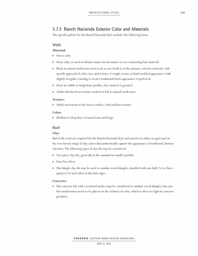
5.21ARCHITECTURAL ST YLES
V E R R A D O CUSTOM HOME DESIGN GUIDEL INES
JULY 21, 2015
5.7.5 Ranch Hacienda Exterior Color and MaterialsThe specific palette for the Ranch Hacienda Style includes the following items.
WallsMaterial: Stucco only
Stone only, or used on distinct major accent masses or as a contrasting base material
Brick in natural earth tones used as an accent detail or as the primary exterior material, with
specific approval of color, size, and texture. A rough, crusty, or hand-molded appearance with
slightly irregular coursing to avoid a traditional brick appearance is preferred.
Stone in rubble or ledgestone profiles, dry-stacked or grouted
Adobe that has been mortar-washed or left in natural earth tones
Texture: Subtle movement in the stucco surface, with medium texture
Color: Medium to deep hues of natural tans and beige
RoofClay:
Barrel tile roofs are required for the Ranch Hacienda Style and must be in either an aged sand or
the rose-brown range of clay colors that authentically capture the appearance of traditional, historic
clay hues. The following types of clay tile may be considered:
Two-piece clay tile, generally in the standard or smaller profiles
Faux Two-Piece
Flat shingle clay tile may be used to emulate wood shingles, installed with one-half (½) to three-
quarter (¾) inch offset at the butt edges.
Concrete: Flat concrete tile with a textured surface may be considered to emulate wood shingles, but care-
ful consideration needs to be placed on the richness of color, which is often too light in concrete
products.

5.22 SECTION FIVE
V E R R A D O CUSTOM HOME DESIGN GUIDEL INES
JULY 21, 2015
Trim and AccentsRailings: Natural wrought or rusted metal, or painted to match a natural metal finish
Windows and Doors: Painted or semi-transparent stain to match an accent color
Trim Details:
Deep chocolate browns, bronzes, or blackish browns

5.23ARCHITECTURAL ST YLES
V E R R A D O CUSTOM HOME DESIGN GUIDEL INES
JULY 21, 2015
5.8 Rural Mediterranean
5.8.1 Rural Mediterranean Exterior CharacterThe Rural Mediterranean Style is distinguished by an informal character. The Rural Mediterranean
Style is primarily composed of simple rectilinear forms, asymmetrical in composition, with gable
or shed roofs creating a charming country appearance, similar to vineyard regions throughout the
world with climatic characteristics similar to those found in Verrado. The primary façade and entry
to this Home are inviting and friendly, and are appealing in an understated manner. Often the win-
dow composition is of regular, vertically proportioned divided lite windows, most often with lou-
vered shutters as accents.
Smaller, simple building massing composed into a charming rural character
Vertical emphasis is raised at primaryguest entry
Chimney detailing differs for added character
Double paired French doors with divided lites offset by small window openings
Recessed auto court behind decorative low walls
Shed roof terminates gabled end mass

5.24 SECTION FIVE
V E R R A D O CUSTOM HOME DESIGN GUIDEL INES
JULY 21, 2015
5.8.2 Rural Mediterranean Massing CriteriaThe Rural Mediterranean Style building mass is generally rectilinear and axial, similar to other
Spanish Styles, but usually resulting in smaller scaled building forms, including the primary mass.
An informal composition of building masses is one of this Style’s distinguishing features, which can
provide the impression that the Home may have evolved over time.
Masses are generally rectilinear, telescoping in height and plan form.
Sometimes random mass configurations are used in response to topography.
Random, linear, and L- or U-shaped mass configurations are utilized.
Some tower mass features may be utilized for vertical accent.
5.8.3 Rural Mediterranean Building ElementsThe following list of major building elements includes those features that are the primary
distinguishing elements of the Style.
Roof Forms Predominantly gable and shed, sometimes limited use of hip roofs
No flat roofs
No conical roofs
Roof pitch ranges from 3/12 to 5/12, with occasional lower slopes at shed roofs, generally over
terraces
Structural Supports Full, round, arched, recessed openings
Predominantly stucco or masonry pilasters
Limited use of precast or stone round columns
5.8.4 Rural Mediterranean Accents and DetailsThe following list of accents and details includes those features that are the distinguishing detail
elements of the Style.
Windows and Doors Square or rectilinear windows with divided lites are the characteristic shape.
Window shapes are placed in an organized pattern and rhythm, and symmetrically organized.
Doors are vertical wood plank or (more limited) carved wood with ornamental designs.
French doors with divided lites may be used on exterior walls, except for the primary entry
door.

5.25ARCHITECTURAL ST YLES
V E R R A D O CUSTOM HOME DESIGN GUIDEL INES
JULY 21, 2015
Trim Details Stucco or masonry coved trim at the roof eave
Exposed wood roof rafters
Shutters proportionate to window size. Shutters can be louvered or plank; composite material is
recommended over wood.
Simple unornamented chimney details
Ornamentation Wrought iron or rusted metal railings, gates, grilles, fences, and the like
5.8.5 Rural Mediterranean Exterior Color and MaterialsThe specific palette for the Rural Mediterranean Style includes the following items.
WallsMaterial: Stucco only
Stone only, or with stone used on distinct major masses or as a contrasting base material
Brick used as an accent detail or as the primary exterior building material, with specific approval
of color, size, and texture
Texture: Heavier textures that incorporate coarser sand into the mix can provide the appropriate
appearance, in addition to undulations in the stucco surface.
Color: Rich earthen hues of gold, khaki, terra cotta, and red for stucco colors
Brick in muted terra cottas, golds, or rose tones, but not vibrant or red
RoofClay:
Barrel tile roofs are required for the Rural Mediterranean Style. Tiles must be either an aged sand
hue or in the rose-brown range of clay colors that authentically captures the appearance of
traditional, historic clay hues. The following types of clay tile may be considered:
Two-piece clay tile, generally in the smaller profiles
Faux Two-Piece
Two-piece clay tile with roman pans

5.26 SECTION FIVE
V E R R A D O CUSTOM HOME DESIGN GUIDEL INES
JULY 21, 2015
Trim and AccentsRailings: Natural wrought or rusted metal, or painted to match a natural metal finish
Windows and Doors: Painted or semi-transparent stain to match an accent color, generally applied to create a richer
aged appearance
Trim Details: The lighter shades of blue-gray and green, and sometimes deep red cranberry hues

5.27ARCHITECTURAL ST YLES
V E R R A D O CUSTOM HOME DESIGN GUIDEL INES
JULY 21, 2015
5.9 Western Regional Design StylesFour different variations make up the Western Regional architectural Style for Verrado: West-
ern Farmhouse, Ranch Territorial, Desert Prairie, and Contemporary Western Regional. Western
Regional architecture—from the rustic territorial ranch compound to the more agrarian farm-
house—is reminiscent of the distinct dwellings of the Western landscape. From the low, horizontal,
ground-hugging profile typical of the Desert Prairie Style to the exposed structural elements of the
Ranch Territorial Style, each Western-Styled Home is designed to harmonize with its natural sur-
roundings and environment. These dwellings are distinguished by either generous roof overhangs,
wide covered porches and patios, and shaded galleries, or massive walls with deep recessed win-
dows, each intended to create a cooler interior environment so that windows may remain open to
promote natural cross-ventilation. Just as the roof overhangs provide cooling shade in the warmer
months, the lower angle of the sun during the winter months helps warm the interior spaces. Other
traditional characteristics include the incorporation of indigenous building materials. These unique
features inherent to the Western Styles build an ideal platform for embracing the outdoors and cre-
ating a wonderful environment perfect for entertaining and socializing.
5.10 Western Farmhouse
5.10.1 Western Farmhouse Exterior CharacterFarmhouse architecture stems from agrarian influences that are a direct response to the warm
western sun, unique agrarian or ranch landscape, and refined craftsmanship of a bygone era. The
Farmhouse Style has a less rustic character than Contemporary Western Regional architecture, an
architectural Style not allowed in Verrado, because it often features wood siding, shutters, and trim
materials reminiscent of the fine carpentry detailing often lost in today’s housing market. If stucco
is used as the exterior material, windows and doors often have trim, and are flanked by shutters. To-
day’s building materials offer the appearance of wood without the negative effects of deterioration,
and provide for fire protection from potential wildfires. The primary feature of the Western Farm-
house architecture is the covered entry or wide veranda designed to provide protection from the el-
ements while providing a semi-public outdoor living space.
5.10.2 Western Farmhouse Massing CriteriaThe Western Farmhouse building mass is predominantly a rectangular block with a one-story porch
with a hip or shed roof. The mass of the two-story house requires a transition to single-story mass
at the front corner and side. The additive building masses can provide the unique appearance of a
Home that was built over time. The central form may expand to create an L-, U-, or H-shaped con-
figuration. Dormers are typically utilized at the roof as minor mass elements.

5.28 SECTION FIVE
V E R R A D O CUSTOM HOME DESIGN GUIDEL INES
JULY 21, 2015
5.10.3 Western Farmhouse Building ElementsThe following list of major building elements includes those features that are the primary
distinguishing elements of the Style.
Roof Forms Predominantly gable roofs, with the use of shed or hip roofs over porches
Hip roof possible, but less common
Pitched dormers; shed dormers are possible, but less common
Roof pitch ranges from 5/12 to 8/12, with occasional lower slopes at shed roofs, generally over
terraces
Structural Supports Predominantly square wood posts, post to beam brackets, beams, and rafter tails
Exposed trusses
Gabled roof ends telescope out to secondary masses
Large gable roofs often have smaller dormers in the upper levels
Parallel site walls at culvert crossing create bridge-like element
Windows are often accented with shutters
Porches are iconic elements
Traditional agrarian forms with basic repetitive details
defi ne the Western Farmhouse character

5.29ARCHITECTURAL ST YLES
V E R R A D O CUSTOM HOME DESIGN GUIDEL INES
JULY 21, 2015
5.10.4 Western Farmhouse Accents and DetailsThe following list of accents and details includes those features that are the distinguishing detail
elements of the Style.
Windows and Doors Square or rectilinear window shapes with standard divided lite configurations
Rectilinear single or French door shapes with standard divided lite configurations
Trim Details Wood posts, post to beam brackets, beams, and rafter tails
Wood window and door trim, or composite products for fire protection
Ornamentation Shutters
Porch railings
Sometimes tile or metal roof awnings over windows
5.10.5 Western Farmhouse Exterior Color and MaterialsThe specific palette for the Western Farmhouse Style includes the following items.
WallsMaterials: Stucco only, or in combination with a stone base
Stone used as accents, such as chimneys, or as an exterior wainscot
Stained lap or board and batten siding in wood or composite products for fire protection
Traditional Western brick (rather than Eastern) with a less rustic-looking texture than the Ranch
Hacienda Style, with used brick discouraged
Texture: Smooth to medium stucco finishes
Natural wood siding, or composite siding textured to simulate natural wood
Color: Stained lap or board and batten siding in colors extending into slate grays, blue/greens, and barn
red hues
Stucco in tans, terra cottas, and other earth tones
Brick colors ranging from warm brown shades into cooler reds

5.30 SECTION FIVE
V E R R A D O CUSTOM HOME DESIGN GUIDEL INES
JULY 21, 2015
RoofFlat Concrete or Clay Shingle: Coloration should not be perfectly monochromatic or have high contrast from tile to tile, and
shall be in the color range of natural wood shake.
Textured shake tile is preferred over slate to reduce potential sheen or glare.
Horizontal alignment can be slightly irregular.
Metal: Painted corrugated or standing seam metal roof may be considered, but a low glare/gloss (LG)
finish is required. This roof may still be denied depending on the specific Lot location. This type
of roof must be used with caution due to the glare potential.
Finishes in rusted metal or zinc are encouraged because they have a very rich color with a dull
finish.
Natural galvanized metals are discouraged unless they are treated upon installation to a natural
dull finish.
Composition Shingle: Colors shall be gray/green, charcoal, or warm gray.
Shingles must be Class A and in the thirty (30) to forty (40) year profiles.
Trim and AccentsRailings: Wood railing appearance, constructed of wood or composite materials
Windows and Doors: May be painted or stained, and can include colors lighter than a medium or deep body color
Trim Details: May be painted or stained, and can include colors lighter than a medium or deep body color

5.31ARCHITECTURAL ST YLES
V E R R A D O CUSTOM HOME DESIGN GUIDEL INES
JULY 21, 2015
5.11 Ranch Territorial
5.11.1 Ranch Territorial Exterior CharacterThe Ranch Territorial Style is directly linked to the romantic charm of the American West and the
ranching legacy of Arizona. This rugged, rustic look is best achieved by using indigenous materi-
als that have a strong association and compatibility with the landscape. Originally, stone was used in
two (2) ways: as a foundation material that acted as a natural extension of the earth, and as an accent
on primary features such as chimney stacks or other distinct exterior forms. Timber elements were
characteristically used for porch railings, rafters, beams, posts, and fascia trim details. Today, com-
posite materials fulfill these same purposes, while adding greater durability. Roof materials were
traditionally influenced by their availability and consisted of simple and functional coverings such as
corrugated metal. Covered porches and wrap-around verandas provide ample space for outdoor
entertaining and socializing.
Simple gabled roofs and broad porch overhangs are
representative of the Ranch Territorial Style
Small secondary windows often with deep recesses
Shed dormers animate the front facade
Shed awnings provide solar protection in a simple manner
Metal roofs with dark colors and low gloss increase textural quality of streetscape
Long front porch with broad roof overhang

5.32 SECTION FIVE
V E R R A D O CUSTOM HOME DESIGN GUIDEL INES
JULY 21, 2015
5.11.2 Ranch Territorial Massing CriteriaThe Ranch Territorial building mass is predominantly a rectangular mass with multiple additive
masses attached to it, giving the overall composition an appearance of being built over time. There is
often a one-story wrap-around hip or shed roof porch. Any primary two-story masses will generally
require a transition to single-story masses, especially at the front corner and sides. The central form
may expand to create an L-, U-, or H-shaped configuration. Shed dormers are typically utilized as
minor mass elements.
5.11.3 Ranch Territorial Building ElementsThe following list of major building elements includes those features that are the primary
distinguishing elements of the Style.
Roof Forms Predominantly gable or shed, with shed or hip roofs used over terraces.
Hip roof possible, but rare historically.
Shed dormers are used to bring daylight into spaces sheltered by a wrap-around porch.
Roof pitch ranges from 4/12 to 6/12, with occasional lower slopes at shed roofs, generally over
terraces.
Structural Supports Predominantly square wood posts, kicker brackets, beams, and rafter tails
Square masonry or stucco pilasters
Round wood post possible, generally related to the New Mexico ranch influence
5.11.4 Ranch Territorial Accents and DetailsThe following list of accents and details includes those features that are the distinguishing detail
elements of the Style.
Windows and Doors Square or rectilinear shapes with standard divided lite configurations on windows
Trim Details Wood posts, post to beam brackets, beams, and rafter tails
Wood or concrete headers

5.33ARCHITECTURAL ST YLES
V E R R A D O CUSTOM HOME DESIGN GUIDEL INES
JULY 21, 2015
Ornamentation Black wrought iron or metal railings, gates, grilles, fences, and the like
Sometimes roof awnings over windows
Shutters
Porch railings
5.11.5 Ranch Territorial Exterior Color and MaterialsThe specific palette for the Ranch Territorial Style includes the following items.
WallsMaterials: Stucco only, or in combination with a stone base
Stone only, or used as accent masses or exterior wainscot only
Traditional Western brick (rather than Eastern) with a less rustic looking texture than the Ranch
Hacienda Style, with used brick discouraged
Texture: Smooth to medium stucco finishes, with mottled finishes possible
Color: Stucco in tans, terra cottas, and other earth tones
Brick colors ranging from warm brown shades into cooler reds
RoofFlat Concrete or Clay Shingle: Coloration should not be perfectly monochromatic or have high contrast from tile to tile, and
shall be in the color range of natural wood shake.
Textured shake tile is preferred over slate to reduce potential sheen or glare.
Horizontal alignment can be slightly irregular.
Metal: A painted corrugated or standing seam metal roof may be considered, but a low glare/gloss
(LG) finish is required. This roof Style still may be denied depending on the specific Lot location.
This type of roof must be used with caution due to the glare potential.
Finishes in rusted metal or zinc are encouraged because they have a very rich color with a dull
finish.
Natural galvanized metals are discouraged unless they are treated upon installation to a natural
dull finish.

5.34 SECTION FIVE
V E R R A D O CUSTOM HOME DESIGN GUIDEL INES
JULY 21, 2015
Trim and AccentsRailings: Wood railing appearance, constructed of wood or composite materials
Windows and Doors: May be painted or stained, and can include colors lighter than a medium or deep body color, or
the deeper browns
Trim Details: May be painted or stained, and can include colors lighter than a medium or deep body color

5.35ARCHITECTURAL ST YLES
V E R R A D O CUSTOM HOME DESIGN GUIDEL INES
JULY 21, 2015
5.12 Desert Prairie
5.12.1 Desert Prairie Exterior CharacterThe Desert Prairie Style is most often associated with the work of Frank Lloyd Wright in the Mid-
west, although the presence of Taliesin West in Arizona demonstrates how the style has been adapted
to other environments. The Desert Prairie Style presented herein utilizes the environmentally sensi-
tive components of the Style and promotes the use of materials and colors that are compatible with
the natural desert environment. This Style reflects the sweeping expanses of the Western landscape,
with long horizontal lines and strong vertical masonry elements. Protective overhangs— the most
predominant element of this Style —provide deep shadows for recessed windows. These broad roof
extensions also provide comfortable outdoor living areas. The overall plan is more linear and rig-
id in plan geometry than most Styles, commonly characterized by cross-axial floor plans. Consistent
window sizing and patterning are indicative of the Desert Prairie Style, commonly distinguished by
rows of ribbon windows that hug the shaded eave line.
Long horizontal roof lines on predominantly one and one-and-a-half story
massing with extensive windows and doors
Windows are often rhythmically placed with horizontal lines Masonry columns and
chimney forms anchor the primary building forms
Hip roof forms step down to meet the site
Driveway leading to concealed garage area
Broad shaded overhangs can extend four (4) to six (6) feet or greater
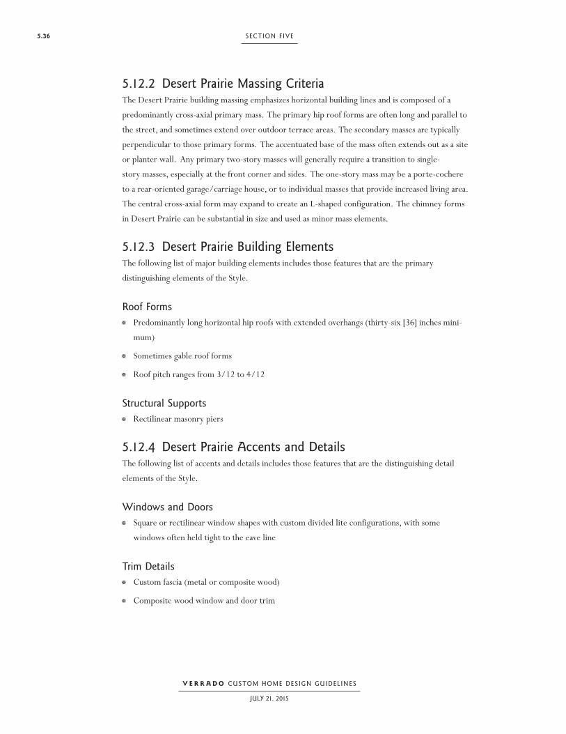
5.36 SECTION FIVE
V E R R A D O CUSTOM HOME DESIGN GUIDEL INES
JULY 21, 2015
5.12.2 Desert Prairie Massing CriteriaThe Desert Prairie building massing emphasizes horizontal building lines and is composed of a
predominantly cross-axial primary mass. The primary hip roof forms are often long and parallel to
the street, and sometimes extend over outdoor terrace areas. The secondary masses are typically
perpendicular to those primary forms. The accentuated base of the mass often extends out as a site
or planter wall. Any primary two-story masses will generally require a transition to single-
story masses, especially at the front corner and sides. The one-story mass may be a porte-cochere
to a rear-oriented garage/carriage house, or to individual masses that provide increased living area.
The central cross-axial form may expand to create an L-shaped configuration. The chimney forms
in Desert Prairie can be substantial in size and used as minor mass elements.
5.12.3 Desert Prairie Building ElementsThe following list of major building elements includes those features that are the primary
distinguishing elements of the Style.
Roof Forms Predominantly long horizontal hip roofs with extended overhangs (thirty-six [36] inches mini-
mum)
Sometimes gable roof forms
Roof pitch ranges from 3/12 to 4/12
Structural SupportsRectilinear masonry piers
5.12.4 Desert Prairie Accents and DetailsThe following list of accents and details includes those features that are the distinguishing detail
elements of the Style.
Windows and Doors Square or rectilinear window shapes with custom divided lite configurations, with some
windows often held tight to the eave line
Trim DetailsCustom fascia (metal or composite wood)
Composite wood window and door trim

5.37ARCHITECTURAL ST YLES
V E R R A D O CUSTOM HOME DESIGN GUIDEL INES
JULY 21, 2015
Ornamentation Custom metal railings, gates, and the like
Carpenter detailing
Unique lighting fixtures
5.12.5 Desert Prairie Exterior Color and MaterialsThe specific palette for the Desert Prairie Style includes the following items.
WallsMaterials: Stucco with stone or masonry wainscot base
Stacked stone used as primary walls or accents, such as chimneys or piers
Custom brick shape and size (Roman)
Concrete block may be considered in split face or fluted patterns in a four (4) inch high module.
Texture: Smooth to medium stucco finishes
Color:
Stucco in tans, terra cottas, and other earth tones
Brick colors range from warm brown shades into cooler reds
RoofFlat Concrete or Clay Shingle: Coloration should not be perfectly monochromatic or have high contrast from tile to tile, and
shall be in the color range of natural wood shake.
Textured concrete shake tile is preferred over slate to reduce potential sheen or glare.
Horizontal alignment can be slightly irregular.
Colors shall be in the gray/green, charcoal, and warm gray range.
Metal:
Painted standing seam or Bermuda profile metal roofs may be considered, but a low glare/gloss
(LG) finish is required, and may be denied depending on the specific Lot location. This type of
roof must be used with caution due to the glare potential.
Finishes in zinc are encouraged because it has a very rich color with a dull finish.
Natural galvanized metals are discouraged for this Style.

5.38 SECTION FIVE
V E R R A D O CUSTOM HOME DESIGN GUIDEL INES
JULY 21, 2015
Trim and AccentsRailings:Metal railing in complementary accent colors, sometimes in deep reds, plums, or greens
Windows and Doors:Metal clad or aluminum in darker accent colors
Trim Details:Natural copper weathered to a dark brown patina, or painted or stained in softer grayed hues
and accents

5.39ARCHITECTURAL ST YLES
V E R R A D O CUSTOM HOME DESIGN GUIDEL INES
JULY 21, 2015
5.13 Craftsman Style
5.13.1 Craftsman Style Exterior Character(This style is only allowed on Town Lots or Park Lots)
Craftsman style philosophy expounds the virtues of fresh air, sunshine, socializing, and an archi-
tectural style in close harmony with nature. The major concepts underlying Craftsman architec-
ture are simplicity of design and an honest use of materials. This style embraces nature through its
low ground hugging profile, which is characterized by gabled roof forms, with large unenclosed
overhanging rakes and eaves that amply shade windows from the hot Arizona sun. Such structur-
al elements as beams, brackets, and rafters are commonly left exposed. Detailed craftsmanship is
expressed in the joinery of structural members and in the window and door divided lite patterns.
Large masonry piers, oftentimes composed of native stone, act as natural extensions of the earth,
supporting wide covered porches. These and other outdoor amenities, including pergolas, trellises,
raised terraces, covered balconies and porte cocheres provide a forum for social interaction while
interacting with the streetscene. Ideally, the symbiosis between indoor and outdoor spaces encour-
ages a communion between dwellers and nature.
Wood posts
Stone or stucco site walls
Predominantly fl at concrete roof tile
Shed or pitched roof dormersExposed rafter tails or outriggers 3” min.
Shed roof over secondary mass
Porch railings add ornamental detail
Custom detailed light fi xtures
Masonry base and chimneyLarge covered porch is a defi ning element
Craftsman Style in a Park or Town Lot

5.40 SECTION FIVE
V E R R A D O CUSTOM HOME DESIGN GUIDEL INES
JULY 21, 2015
5.13.2 Craftsman Style Massing CriteriaCraftsman style philosophy expounds the virtues of fresh air, sunshine, socializing, and an archi-
tectural style in close harmony with nature. The major concepts underlying Craftsman architec-
ture are simplicity of design and an honest use of materials. This style embraces nature through its
low ground hugging profile, which is characterized by gabled roof forms, with large unenclosed
overhanging rakes and eaves that amply shade windows from the hot Arizona sun. Such structur-
al elements as beams, brackets, and rafters are commonly left exposed. Detailed craftsmanship is
expressed in the joinery of structural members and in the window and door divided lite patterns.
Large masonry piers, oftentimes composed of native stone, act as natural extensions of the earth,
supporting wide covered porches. These and other outdoor amenities, including pergolas, trellises,
raised terraces, covered balconies and porte cocheres provide a forum for social interaction while
interacting with the streetscene. Ideally, the symbiosis between indoor and outdoor spaces encour-
ages a communion between dwellers and nature.
5.13.3 Craftsman Style Building ElementsThe following is a list of architectural characteristics of this Style, grouped by major building ele-
ments or accents and details.
Roof Forms Predominantly gable roofs, with use of shed over terraces or secondary masses.
Shed or pitched dormers
Limited use of hip roof, typically at wrap around porch elements.
Roof pitch ranges from 4/12 to 8/12 or greater, with occasional lower slopes at shed roofs gen-
erally over terraces.
Structural Supports
Tapered square composite wood posts
Multiple wood posts with or without brackets
Wood beams, brackets, and rafter tails
Stone or masonry piers

5.41ARCHITECTURAL ST YLES
V E R R A D O CUSTOM HOME DESIGN GUIDEL INES
JULY 21, 2015
5.13.4 Craftsman Style Accents and DetailsThe following list of accents and details includes those features that are the distinguishing detail ele-
ments of the Style.
Windows and Doors Square or rectilinear window shapes with standard or custom divided lite configurations. Used in paired or tripled configurations.
Trim DetailsWood posts, kicker brackets, beams, and rafter tails.
Composite wood window and door trim.
Ornamentation Porch railings
Carpenter detailing
Unique lighting fixtures
5.13.5 Craftsman Style Exterior Color and MaterialsThe specific palette for the Craftsman Style includes the following items.
WallsMaterials: Stucco only, or in combination with a stone base.
Stone used as accents such as chimneys or as an exterior wainscot in rubble or stacked profiles.
Stained lap or board and batten siding in wood, or composite products for fire protection.
Traditional Western brick (rather than Eastern) in a natural or painted finish.
Texture: Smooth to medium stucco finishes. Natural wood siding, or composite siding textured to simulate natural wood.
Color:
Painted lap or board and batten siding in colors extending into warm grays and browns.
Stucco in the lighter tans, or deeper values of terra cottas and other earth tones.
Brick colors ranging from warm brown shades into cooler reds.

5.42 SECTION FIVE
V E R R A D O CUSTOM HOME DESIGN GUIDEL INES
JULY 21, 2015
RoofFlat Concrete or Clay Shingle: Coloration should not be perfectly monochromatic or have high contrast from tile to tile, and
shall be in the color range of natural wood shake.
Textured shake tile is preferred over slate to reduce potential sheen or glare.
Horizontal alignment can be slightly irregular.
Metal:
Painted corrugated or standing seam metal roof may be considered, but a low glare/gloss (LG)
finish is required. This roof Style still may be denied depending on the specific Lot location. This
type of roof must be used with caution due to the glare potential.
Finishes in zinc are encouraged because it has a very rich color with a dull finish.
Natural galvanized metals are discouraged unless they are treated upon installation to a natural
dull finish.
Composite Shingle:
Colors shall be in the gray/green, charcoal, and warm gray range.
Shingles must be Class A and in the thirty (30) to forty (40) year profiles.
Trim and AccentsRailings:Wood railing appearance, constructed of wood or composite materials.
Windows and Doors:May be painted or stained, and can include colors lighter than a medium or deep body color.
Trim Details:May be painted or stained, and can include colors lighter than a medium or deep body color.

5.43ARCHITECTURAL ST YLES
V E R R A D O CUSTOM HOME DESIGN GUIDEL INES
JULY 21, 2015
5.14 Contemporary Western Regional Style
5.14.1 Applicability and InterpretationInterpretation and applicability of the Contemporary Western Regional style shall be at the sole
discretion and opinion of the Design Review Committee. Unlike traditional, historic-based,
architectural styles that have a long history of forms, shapes, elements, colors, materials and
details that can be clearly defined by the applicable traditional architectural style, “contemporary”
design themes do not have the same set of design parameters and references. Furthermore,
“contemporary” design themes (in the general sense) often have a significantly broader palette of
forms, shapes, elements, materials and colors; and with less definition than the traditional, historic-
based styles.
Therefore, any Owner, Designer or Applicant wishing to utilize the Contemporary Western
Regional architectural style must acknowledge and accept the fact that the Design Review
Committee is given significant “subjective” authority to interpret and apply the design criteria for
this style in the sole discretion and opinion of the Design Review Committee. The determination
of what is “acceptable” contemporary design and what is “not acceptable” contemporary design rests
solely with the Design Review Committee.
Due to the proximity of homes designed in “traditional” architectural styles, greater scrutiny will
be placed on the review of the home placement, building massing, overall form, composition,
geometry, exterior materials and colors, and architectural details of homes design in the
Contemporary Western Regional architectural style. In some cases, a contemporary design may
be deemed by the Committee to be incompatible with the context of adjacent homes, either
built or planned. The Committee reserves all rights to not approve a contemporary design if the
Committees deems it to be incompatible with the neighborhood or street character.
In general, and in the sole interpretation of the Design Review Committee, the following design
philosophies will apply to the Design Review Committee’s evaluation of any proposed
contemporary home designs.
Any contemporary design shall be appropriate to the character of the natural desert
environment; and to the climatic and environmental considerations of the Arizona desert. The
intent is that the design of the home blends quietly with the natural desert instead of standing
out against it.

5.44 SECTION FIVE
V E R R A D O CUSTOM HOME DESIGN GUIDEL INES
JULY 21, 2015
Any contemporary design will likely require the use of multiple natural materials that blend with
the natural desert. Designs with monochromatic color schemes and/or only one (1) primary
exterior wall material will not likely be approved. For example, a proposed contemporary
design in which the only exterior wall material is stucco will not likely be approved. A
significant use of a secondary exterior wall material will likely be required for all contemporary
designs. (FYI: Windows, doors, and glass are not considered an exterior wall material for
the sake of this criteria.) Acceptable contemporary designs are the result of a thoughtful
composition of forms, massing, colors, textures and different materials.
The Design Review Committee reserves all rights to deny or not approve any contemporary
design that the Committee feels in its sole opinion:
Is too bold, boxy, blocky, modern, stark, plain, unarticulated, boring, or
overly simple.
Lacks sufficient color, texture, shade and shadow.
Has an inappropriate response to topographic conditions. A contemporary
design must feel strongly anchored into the natural site and may not feel like
it sits on or floats above the natural terrain.
Lacks an appropriate response to environmental conditions. For example,
large windows without proper shading or overhangs would be considered an
inappropriate response to environmental conditions.
Includes colors or materials that are light, bright, shiny, reflective or
otherwise in contrast to the subdued natural desert environment and the
overall objectives of the community character.
Lacks sufficient architectural detail, articulation, symmetry, balance, order,
organization and repose.
Lacks consistency and continuity. An acceptable contemporary design must
be an expression of a single, well-composed concept. Divergent themes and
different design characters are not allowed within the same concept.
Results in a design that is random, chaotic, unorganized or arbitrary.
Results in a design that does not feel “residential” in character, scale, massing,
materials or details.
Does not appear appropriate for the natural desert environment and for the
established town-like character of Verrado.

5.45ARCHITECTURAL ST YLES
V E R R A D O CUSTOM HOME DESIGN GUIDEL INES
JULY 21, 2015
Due to the variety of contemporary design interpretations; due to the unique and one-of-a-
kind contemporary design ideas; and due to the subjective nature of the review of contemporary
designs; the approval of a contemporary design by the Committee, including any of its particular
shapes, forms, character, elements, details, colors or materials does not establish a precedent;
nor does it obligate the Committee to ever approve a similar shape, form, character, element,
detail, color or material again in the future even if similar conditions exist. In other words, just
because an element was approved for one contemporary design does not mean the Committee is
obligated to approve a similar element again in the future even if similar conditions exist.
Any Owner, Designer or Applicant that elects to use the Contemporary Western Regional style
acknowledges and accepts these conditions.
5.14.2 Contemporary Western Regional - Not Allowed in Parcel 5.701The Contemporary Western Regional style is not allowed on any lot in Parcel 5.701.
5.14.3 Contemporary Western Regional - Additional Submittal RequirementsDue to the wide variety of expressions and interpretations of the Contemporary Western Regional
style; and due to the interpretation considerations noted above; it is important to establish a clear
design direction BEFORE commencing design. Therefore, if the Owner, Designer or Applicant
wishes to use the Contemporary Western Regional style, they must submit the following to the
Committee for consideration and evaluation BEFORE starting design:
Declare the “derivation style” of which the contemporary interpretation is based. For example, a
contemporary interpretation of the Western Farmhouse style; or an contemporary interpretation
of the Ranch Territorial style; or a contemporary interpretation of the Desert Prairie style.
Submit a collection of photographic images that represent the general design intent and general
design direction that is desired by the Applicant for the exterior design of the home.
The Committee will evaluate these photographic images to determine if the proposed design
character complies with the Committee’s interpretation of the Contemporary Western Regional
style. The purpose of these additional submittal requirements is to help establish a clear design
direction BEFORE the Applicant starts design.

5.46 SECTION FIVE
V E R R A D O CUSTOM HOME DESIGN GUIDEL INES
JULY 21, 2015
5.14.4 Contemporary Western Regional Exterior CharacterThe Contemporary Western Regional Style is directly linked to and inspired by the established
and defined Western design styles outlined in Section 5.10 of these Design Guidelines. The
Contemporary Western Regional style is typically designed in a fresh interpretation derived from
the authentic Western Farmhouse, Ranch Territorial, and Desert Prairie styles.
Selecting the Contemporary Western Regional architecture style can lead to a variety of potential
design responses, but a Contemporary design must be derived from one of the established and
defined Western Styles outlined in Section 5.10 of Design Guidelines so that the Contemporary
design is compatible in the context of the community and not a foreign element in Verrado. This
reinterpreted contemporary design expression often incorporates new roof or building forms or
new exterior materials, or composes the elements in a unique manner.
Contemporary designs exhibit a deliberate simplification of the original architectural components,
and the resultant design can range in appearance from subtle to bold. The details are typically more
precise, minimalist, or purposely striking to express the detail in a noticeable, thought-provoking
manner. Although details may be more minimalist, the absence of detail is not appropriate.
For instance, if the original derivation style is a Desert Prairie Style, where the ornamental
craftsmanship is expressed in the windows and doors or other custom exterior detailing, the
Contemporary expression might be larger windows without traditional divided lites, and an
accentuated roof overhang and eave details, yet the overall roof forms and exterior materials clearly
are reminiscent of the original Desert Prairie Style.
This Contemporary Western Regional look is best achieved by using indigenous materials in unique
ways that have a strong association and compatibility with the landscape. Regardless of the design
direction selected, all Contemporary designs must be compatible with the site context or the
other traditionally-styled homes in Verrado. For this reason, approval of Contemporary designs
can be more difficult to obtain because they are by definition more subjective in their appeal and
interpretation.

5.47ARCHITECTURAL ST YLES
V E R R A D O CUSTOM HOME DESIGN GUIDEL INES
JULY 21, 2015
5.14.5 Contemporary Western Regional Massing CriteriaThe Contemporary Western Regional building massing is generally free of specific rules, but
predominantly is a rectangular mass with multiple additive masses attached to it, giving the overall
composition an appearance of being built over time. Any primary two-story masses will generally
require a transition to single-story masses, especially at the front, corners and sides. The central
form may expand to create an L-, U-, or H-shaped configuration. In general, curved, rounded,
meandering, or organic shapes are not allowed. Curved forms may be appropriate for secondary
elements and massing, but not likely for primary building forms.
Chimney mass creates a vertical emphasis
Broad trellis overhang shades outdoor patio
Curved roof form is limited to one expression for maximum accent
Individual masses are composed along contours to integrate into the slope
Segmented garage doors can often provide accents of decorative metal
Creative blends of contemporary details and traditional forms
integrate quietly into a hillside Lot

5.48 SECTION FIVE
V E R R A D O CUSTOM HOME DESIGN GUIDEL INES
JULY 21, 2015
5.14.6 Contemporary Western Regional Building ElementsThe following list of major building elements includes those features that are the primary
distinguishing elements of the Style.
Roof Forms
Predominantly low sloping gable or shed roofs, with shed, hip or flat roofs used over terraces.
Hip roof is possible, especially for contemporary interpretations of the Desert Prairie style.
Flat roof with parapets.
Non-Parapetted Flat Roofs; which are subject to strict compliance with Section 4.4.3 of these
Design Guidelines.
Roof pitch ranges from 2/12 to 6/12, with occasional lower slopes at shed roofs, generally over
terraces.
Overhangs are generally deep and broad with deep shade at patios and terraces.
Unconventional roof forms, such as a segmented arch roofs, butterfly roofs, geodesic roofs, or
odd-shaped roofs will not likely be allowed.
Structural Supports
Rectilinear wood or steel posts, kicker brackets, beams, and rafter tails.
Masonry or stucco pilasters.
Stone “rib walls” or “spine walls” that are created as strong masonry elements that support broad
overhanging roofs.
5.14.7 Contemporary Western Regional Accents and DetailsThe following list of accents and details includes those features that are the distinguishing detail
elements of the Style.
Windows and Doors
Square or rectilinear shapes with custom configurations and divided patterns. In general,
windows have vertical proportions. Horizontally proportioned windows may be allowed, but
the Committee reserves all rights to not allow horizontally proportioned windows, in the sole
opinion of the Committee.
Corner windows, frameless glazing, and mitered-glass windows.
Typically in contemporary design interpretations, the top of the windows extends all the way up
to the soffit, with no exposed header or lintel.

5.49ARCHITECTURAL ST YLES
V E R R A D O CUSTOM HOME DESIGN GUIDEL INES
JULY 21, 2015
Windows and sliding glass doors are often expressed as “voids” between the roof, wall masses,
and the floor plane; instead of appearing as “holes” in a wall plane.
Windows located in an exterior wall are typically deeply recessed to give the impression of thick
substantial walls.
Custom configurations of expansive glass areas and sliding glass doors are common. Small posts
or supports between assemblies of windows or sliding glass doors shall be clad in break metal to
match the color of the window frames. This results in the grouping of windows or sliding glass
doors to appear as a unified assembly.
Trim Details
Wood, composite-wood, cement fiber trim, or metal custom fascias or eaves.
Stucco fascias are not allowed.
Wood, metal, stone, or concrete headers and sills.
Ornamentation
Custom designed metal railings, gates, grilles, fences, chimney caps, and trellises.
Metal awnings and bracket details over windows.
Custom lighting designs.
Staggered garage doors add relief to the street elevation
Butt-joined glass can offer uninterrupted views
Site wall layout responds to the architectural form
Masonry site walls with geometric patterns of openings
Stepped geometric building forms with a bold sloping roof
opens views to the hillsides uphill

5.50 SECTION FIVE
V E R R A D O CUSTOM HOME DESIGN GUIDEL INES
JULY 21, 2015
5.14.8 Contemporary Western Regional Exterior Color and MaterialsThe specific color and material palette for the Contemporary Western Regional Style includes the
following items.
WallsMaterials:
Stucco in combination with a stone or masonry.
Stone only, or used as accent masses or exterior wainscot only.
Traditional Western brick (rather than Eastern brick).
Board formed concrete only, or used as accent masses or exterior wainscot only.
Metal panels or metal siding in dark colors and natural patinas.
Standard, scored, and split-face concrete masonry units (CMU or concrete block) are not
allowed because they lack residential character.
Burnished architectural CMU, heavy sandblasted CMU, and sandblasted slump block may be
approved at the sole discretion of the Committee.
Thin materials, such as flagstone and tiles, are not allowed for exterior vertical wall surfaces.
Materials the are commonly used for flooring may not be used on wall surfaces.
Texture:
Sand finish or smooth finish stucco.
Textural stone in dark earthy colors that anchors into the natural terrain.
Exposed aggregates in masonry units.
Color:
Stucco colors in subtle hues in grays, greens, tans, taupes, terra cottas, and other earth tones.
Stone and masonry colors in generally dark natural brown and grey shades and color ranges.
RoofFlat Concrete or Clay Shingle:
Coloration should not be perfectly monochromatic or have high contrast from tile to tile, and
shall be in the color range of natural wood shake.
Textured shake tile is preferred over slate to reduce potential sheen or glare.

5.51ARCHITECTURAL ST YLES
V E R R A D O CUSTOM HOME DESIGN GUIDEL INES
JULY 21, 2015
Metal:
Metal roofs may be denied depending on the specific Lot location. Metal roofs must be used with
caution due to the potential for glare and reflectivity.
Factory-finished corrugated or standing seam metal roof may be allowed if approved by the
Committee. Metal roof colors shall be dark and earth tones. No bright, light, bold, reflective,
or shiny metal roof materials will be allowed. A low glare/gloss (LG) finish is required.
Finishes in rusted metal or natural metals such as copper and zinc are encouraged because these
materials have very rich color with a dull finish. Copper roofing must be allowed to naturally
patina to a dark brown “dirty penny” finish.
Exposed galvanized metals are not allowed.
Site-applied painted metal roof materials are not allowed. (Factory finished metal roof materials,
such as Kynar finishes, are acceptable.)
Contemporary hillside home on twenty-fi ve (25) percent slopes along Golf Course
Driveway leading to garage hidden from street and Golf Course views
Combination of primarily gabled roof forms counterbalanced with occasional fl at roof forms
Side yard pool is perched for maximum views and is accessible from main level
Outside patio overlooking Golf Course demarked with low wall

5.52 SECTION FIVE
V E R R A D O CUSTOM HOME DESIGN GUIDEL INES
JULY 21, 2015
Trim AccentsRailings:
Constructed of wood, metal, or composite materials.
Wrought iron railings are required to have an appropriate level of detail to compliment the style
of the home. Simple vertical pickets are not sufficient.
Cable railings shall be reviewed on a case-by-case basis and in the sole discretion of the
Committee
Glass railings shall be reviewed on a case-by-case basis and in the sole discretion of the
Committee.
Windows and Doors:
May be metal or wood, painted or stained, and can include unique but subtle accent colors.
Frameless glazing, butt-glazing, and mitered-glass windows are appropriate.
Trim Details:
May be painted or stained, and can include unique but subtle accent colors

SECTION SIX:
Landscape Design

6.2 SECTION SIX
V E R R A D O CUSTOM HOME DESIGN GUIDEL INES
JULY 21, 2015
6.1 Design PhilosophyThere are abundant opportunities to create exceptional outdoor living environments within Home
Sites in Verrado. With a favorable climate most parts of the year, comfortable outdoor rooms can ex-
tend the living environment of the main Home. Transitioning landscape elements from the private
yard to the natural open space is required. The transition zones are to appear as seamless blends of
native and adaptive plants, and composed in a more naturalistic manner. The Home and its associat-
ed enhanced landscape should sensitively fit into their natural surroundings in a well-crafted manner
and should never overwhelm what is the most valuable asset of Verrado Custom Home sites—their
natural beauty. This asset is of value not only to those living in Verrado, but also to other adjacent
neighborhoods and Homes from which it is Visible.
6.2 Design PrinciplesLandscape design of each Lot are guided by principles of composition that establish a framework
for creating aesthetically inspiring outdoor living spaces. The Home landscape is an extension of the
character set within the surrounding natural environment. Planting layouts, organized to transition
from natural densities and patterns at the edges of the Building Envelope to more lush compositions
within the Private Zone, are encouraged.
6.2.1 Accenting the Architectural Style of the HomePlantings and hardscape elements within the Private and Semi-private Zones, which are described in
detail later in this section, should relate closely to the character of the Home. Homes designed to be
less formal and more rustic in nature can be complemented with a more naturalistic landscape aes-
thetic. The Home is an enclave that nestles into the natural landform surrounding it. Use of appro-
priate materials and finishes that complement the architectural Style of the Home is essential. The
landscape design should follow the same disciplines of proportion, scale, textures, patterns, col-
ors, and rhythm that are used to create the architectural Style of the Home. The ability of plants and
landscape features to accentuate the functional and visual quality of the Home cannot be overstated.
The Grounds are considered an integral component of the Home environment. To gain maximum
benefit from the landscape design, the Grounds and landscape must be considered during the con-
cept phase of the Home. Layering is encouraged on Lots to provide spatial depth and variety in the
massing forms. With layering, masses of plants are arranged behind one another in combinations of
height, texture, and color, to form a hierarchy. The density and color intensity of planting arrange-
ments should vary on the Grounds. Focal areas should be identified and can be given more promi-
nence by the use of accent plants, increased density of shrubs or color, or a greater variety of plants.
Emphasis can be placed on pedestrian and vehicular entry locations, walkways, gate areas, portals,
or doors.

6.3LANDSCAPE DESIGN
V E R R A D O CUSTOM HOME DESIGN GUIDEL INES
JULY 21, 2015
6.2.2 Landscape CharacterThe landscaped yard plays an important role in the creation of the Home environment by providing
functional and pleasing outdoor living spaces as well as enhancing and completing the architectur-
al character. The enhanced landscape also increases the quality of outdoor spaces and, together with
hardscape elements, creates outdoor rooms that are extensions of interior spaces. These outdoor
rooms are appealing because they blend with the floor plan of a Home. Yards will be an extension of
individual expression, with no two looking or feeling alike. Plant selections, quantities, associations,
and placement combine to maximize the effects of form, color, and texture.
6.3 General Landscape Design Considerations
6.3.1 Landscape Architect/Designer SelectionThe Landscape Architect plays an important role in the design team, and often is the coordina-
tor of the entire exterior design of hardscape and softscape. Careful evaluation and selection of this
member of the design team must be made to ensure the highest quality of design and construction.
Landscape designs of Homes must be completed by a licensed Landscape Architect (or a custom res-
idential landscape designer prequalified by the Design Review Committee, or specifically approved
by the Design Review Committee). Homeowners are encouraged to seek out Landscape Architects
who have consistently, and successfully, performed work on similar Custom Home environments.
6.3.2 Homeowner’s Responsibilities for Landscape ConstructionIt is important to remember that some Lots will have native vegetation existing within the Lot, and
a predetermined Building Envelope that delineates the limits of disturbance allowed. Other Lots
have been fully graded and cleared of native vegetation. The primary distinction between these two
(2) Lot conditions is the amount of landscape construction and/or revegetation required by the Ho-
meowner. In general, there are three (3) types of Lots. Lot types are listed below.
Natural Foothill Lots (Parcel 5.803, Parcel 5.804, and Portions of Parcel 3.101)Natural Foothill Lots are characterized by existing native vegetation remaining on the Lot and an
established predetermined Building Envelope. The Homeowner is responsible for all landscape
construction and revegetation within the Lot to the street curb, including any existing areas of dis-
turbance along the street or utility corridor.
Graded Foothill Lots (Parcel 5.803, Parcel 5.804, and Portions of Parcel 3.101)Graded Foothill Lots are characterized by gently sloping pads graded for development, no existing
native vegetation remaining on the Lot, with an established predetermined Building Envelope. The
Homeowner is responsible for all landscape improvements within the entire Lot to the street curb
and all areas outside of the Building Envelope.

6.4 SECTION SIX
V E R R A D O CUSTOM HOME DESIGN GUIDEL INES
JULY 21, 2015
Town Lots and Park Lots (Parcel 5.802 and Portions of Parcel 3.101)Town Lots and Park Lots are smaller, and characterized by having level pads graded for develop-
ment, having no existing native vegetation remaining on the Lot, and having setbacks established on
each side of the Lot. The Homeowner is responsible for all landscape construction within the limits
of the Lot to the sidewalk and/or street.
Once street construction and utility installation are complete, the Master Developer will have
streetscape landscape designed and installed along a majority of the street. This streetscape will gen-
erally be located behind the curb to the sidewalk or back of P.U.E., including the sidewalk if pro-
vided. For the purposes of Lot development, the streetscape landscape is considered an existing
condition to remain, and be protected during construction. The Builder is responsible for repair
and/or replacement of all streetscape landscape damaged during construction to the satisfaction of
the Master Developer.
6.3.3 Planting ZonesWithin the buildable area, the Grounds of a Lot can be divided into landscape zones that define the
type, quantity, and manner of plantings that may occur. Zones are designated by their proposed use,
level of privacy, and visibility from streets and neighboring residences. Though each zone is guid-
ed by different but complementary design criteria, it is essential that a unified landscape character
be presented on each Home Site. The Owner’s Landscape Architect must determine which of the
zones to apply to which portions of the Lot. The following is a list of the five primary zones that ap-
ply to each Lot.
Tree-lined streets frame views of the Home and front Yard on Park Lots or Town Lots

6.5LANDSCAPE DESIGN
V E R R A D O CUSTOM HOME DESIGN GUIDEL INES
JULY 21, 2015
Native ZoneThe Native Zone is intended to mimic the natural desert in its plant variety, pattern, composition,
and density. For this reason, the Native Zone will differ from area to area in Verrado to account for
local differences in the natural landscape.
In the Custom Home neighborhoods, Natural Foothill Lots will have Building Envelopes set with-
in existing native vegetation and terrain. Other Lots, including Graded Foothill Lots, Park Lots, and
Town Lots, have been mass graded, and all existing vegetation has been salvaged or removed. On
Lots that have been mass graded, an enhanced revegetation must occur throughout the entire Lot.
The Landscape Architect must study and determine the conditions on each site to calculate the re-
quirements for this zone. The following are guidelines for the Native Zone:
This zone includes all areas outside of the Building Envelope, those areas outside of perimeter
walls and fences, and those areas that are not designated as Semi-Private and Private Zones.
Turf is not allowed in the Native Zone.
Refer to the Verrado List of Acceptable Plants for plant species allowed in the Native Zone.
Within the Natural Foothill Lots:
Maintain a natural landscape buffer of undisturbed native, or native revegetation, landscape along
all street frontages. Minimize disturbance of natural landscape in areas where driveways and
walkway connections are made.
When revegetation is required, provide plants in densities and patterns found in the adjacent nat-
ural desert based on site-survey field analysis of adjacent native desert areas of similar topogra-
phy. Increased densities may be required if adjacent natural areas are deemed too low density.
Salvage and relocation of existing trees located within the Building Envelope is allowed. In cas-
es where relocation cannot be accommodated within the Building Envelope, salvaged trees may
be relocated on the Lot, and outside of the Building Envelope with written permission from the
Design Review Committee.
Within the Graded Foothill Lots Only:
Revegetation will be required on these Lots in densities and patterns found in the adjacent natu-
ral desert based on site-survey field analysis of adjacent native desert areas of similar topography.
Increased densities may be required if adjacent natural areas are deemed too low density.
Within the Town Lots and Park Lots:
This zone only apply to Park Lots abutting Adjacent Lots with Building Envelopes or natural
open space outside of the Building Envelope.

6.6 SECTION SIX
V E R R A D O CUSTOM HOME DESIGN GUIDEL INES
JULY 21, 2015
Enhanced ZoneThe Enhanced Zone will have more diverse species of plants to create an enhanced desert character.
Plant selections can include plants that are native, or adaptable, to the Sonoran Desert Region. Plant
massing in this zone should be less formal and layered than those found in the Semi-private Zone.
The following guidelines apply to the Enhanced Zone:
Turf is not allowed in the Enhanced Zone.
Refer to the Verrado List of Acceptable Plants for plant species allowed in the Enhanced Zone.
Within the Natural Foothill Lots and Graded Foothill Lots Only:
This zone is located in the front part of the Lot along driveways and surrounding the front por-
tions of the Home, and will be Visible from the street, neighboring Lots, and points of view
within the Community.
Within the Town Lots and Park Lots Only:
This zone is located in the front and rear edges of the Lot, including the streetscape area between
the sidewalk (if provided) and street curb.
ST
RE
ET
Native Zone
Enhanced Zone
Private Zone
Blend of Golf Course landscape and native landscape
Streetscape landscape by Owner in Natural Zone
G o l f C o u r s e
Planting zone diagram — Natural Foothill Lots
Undisturbed natural desert landscape
Semi-private Zone
NZ
NZ
EZ
EZ
EZ
SpZ
SpZ
SpZ
PZ
PZ
EZ
Streetscape Zone
SZ
SZ

6.7LANDSCAPE DESIGN
V E R R A D O CUSTOM HOME DESIGN GUIDEL INES
JULY 21, 2015
Semi-private ZoneThe Semi-private Zone will have significantly more diverse species of plants compared to the En-
hanced Zone. Plant selections can include plants that are native and those that are adapted to the
Sonoran Desert from other regions. Plant massing in this zone can be more formal and layered than
that found in the Enhanced Zone, and relates closely to the site architecture. The following guide-
lines apply to the Semi-private Zone:
Turf is allowed in the Semi-private Zone.
Refer to the Verrado List of Approved Plants for plant species allowed in the Semi-private Zone.
Within the Natural Foothill Lots and Graded Foothill Lots Only:
This zone is located in the front and rear part of the Home within arrival courts, front entries,
and rear yards, and will be partially Visible from the street, neighboring Lots, and points of view
within the Community.
Within the Graded Golf Course Lots and Town Lots Only:
This zone is located in the front and rear part of the Home within front yards, front entry areas,
and rear yards, and will be partially Visible from the street, neighboring Lots, and points of view
within the Community.
Planting zone diagram—Graded Foothill Lots
Enhanced Zone
Semi-private Zone
Blend Golf Course landscape with restored natural landscape
Native Zone
GO
LF C
OU
RSE
Private Zone
STREET
SZ
SZ
Streetscape Zone
NZ
NZ
NZ
EZ
EZ
EZ
SpZ
SpZ
SpZ SpZ
PZ

6.8 SECTION SIX
V E R R A D O CUSTOM HOME DESIGN GUIDEL INES
JULY 21, 2015
Private ZoneThe Private Zone contains the most diverse and adapted desert plant species that may include plants
from coastal/arid regions and non-native plants. Plant massing in this zone can be formal and lay-
ered as in the Semi-private Zone, and relates closely to the architecture. This zone will be applied in
areas that are contained behind walls or architectural edges of significant height to conceal the view
of non-native plants from a distance. The following guidelines apply for the Private Zone:
This zone may not be Visible from the street or from other points in the Community and may be
only minimally Visible from neighboring Lots.
Exotic and lush plantings within this zone must generally be contained within building walls or
freestanding walls.
Except for Town Lots and Park Lots, non-native trees that will grow higher than the roof ridge-
lines, or will become Visible from the street and neighboring Lots upon maturity, are not al-
lowed.
Turf is permitted in this zone.
Locate more ornamental plant species adjacent to the Home, and more native plant species at
the outer edges of the zone.
Planting zone diagram—Town Lots and Park Lots along Golf Course or Open Space
Front yard landscape and side yards fronting streets should complement formal character and plant species of existing streetscape
Semi-private Zone
Existing streetscape(by Developer)
Enhanced Zone
Private Zone
Blend of Golf Course or open space landscape and rearyard landscape not contained withinwalls or patios
Existing streetscape(by Developer)
STREET
GOLF COURSE or OPEN SPACE
PZ
SZ
SZ
EZ
NZNZ
EZSpZ
SpZ
SpZ
SpZ
SpZSpZ
PZ
PZ
PZ
PZ
Streetscape Zone

6.9LANDSCAPE DESIGN
V E R R A D O CUSTOM HOME DESIGN GUIDEL INES
JULY 21, 2015
Planting zone diagram—Town Lots at interior of Parcel 5.802
Streetscape ZoneThe Streetscape Zone is the area adjacent to the street edge. Prior to design, all utility and neigh-
borhood service locations must be verified. The following guidelines apply to the Streetscape Zone:
Within the Natural Foothill Lots and Graded Foothill Lots Only:
This zone is located along the street edge for the entire length of the Lot, and will vary in depth
due to uneven limits of natural landscape disturbance.
Revegetation using plants from the Native Zone palettes is the responsibility of the Owner.
One (1) tree minimum per average fifty (50) lineal feet of Streetscape Zone frontage is required.
Within the Town Lots and Park Lots Only:
Trees and understory plants are preprogrammed and installed by the Developer.
Each Lot has a proposed driveway location that does not interrupt the street tree spacing. Drive-
way location can shift, but street tree locations are considered fixed.
Proposed driveway locations have sleeves below and no shrubs/groundcovers. If driveway
location changes at Owner’s request, the Owner is responsible for replacement of landscape
and sleeves, as well as, relocation of irrigation lines and equipment. Replacement planting must
match size, quality, and species of existing plants scheduled for removal, at the time of removal.
Enhanced Zone
Semi-private Zone
Private Zone
STREET
Streetscape Zone
PZ
PZ
PZPZ
PZ
PZ PZ
SpZSpZ
SpZ
SpZ
SpZ
SpZ
EZ
EZ
EZ
EZ
EZ
SZ
SZ
SZ

6.10 SECTION SIX
V E R R A D O CUSTOM HOME DESIGN GUIDEL INES
JULY 21, 2015
6.3.4 Plant Transition from Zone to ZoneWhen No Vertical Separation Is ProvidedIn areas where two zones abut each other and where a wall or architectural edge does not exist,
plant material selections, layout arrangement, and densities shall blend seamlessly without abrupt
changes.
When Vertical Separation Is ProvidedIn areas where two zones abut each other and where vertical walls or architectural edges do exist,
abrupt change is allowed, and can often enhance the dramatic effect caused by the contrast in land-
scape character.
6.3.5 Outdoor Living EnvironmentsPlant materials and landscape structures are suitable form-giving devices in the creation of outdoor
rooms. Spatial definition can be created with tree overstories and hedge walls. In addition, undis-
turbed dense native vegetation can provide a layer of privacy, reducing the need for perimeter walls.
Planting zone diagram—Town Lots and Park Lots in Parcel 3.101
SpZSpZ
PZ
PZ
EZ
EZ EZ
EZ
SZ
SZ
SZ
STREET
STRE
ET
Streetscape Zone
Enhanced Zone
Semi-Private Zone
Private Zone

6.11LANDSCAPE DESIGN
V E R R A D O CUSTOM HOME DESIGN GUIDEL INES
JULY 21, 2015
6.3.6 Turf GrassThe decision to use turf as a ground cover is appropriate for the character of outdoor rooms be-
ing created, but should be tempered to avoid excessive turf coverage in non-functional areas. Turf
should generally be used as an extension of outdoor spaces such as porches and patios. In most cas-
es, the shape of turf areas, formal and informal, should complement the Style of the Home. Yards,
courtyards, and garden areas are considered extensions of interior spaces and can enhance the qual-
ity of the living environment when designed for comfort, visual appeal, and functional uses. On a
case-by-case basis, as part of the landscape design review, the Design Review Committee will re-
view and approve turf area by coverage amount, minimum dimensions, and location on each Lot.
Turf usage must meet the following general criteria:
Turf cannot be prominently Visible from afar, and cannot be Visible from the street, except as
specifically allowed below for Town and Park Lots. Tree massings and courtyard walls can be ef-
fectively used to limit the visibility of large turf areas.
Planting turf on sloped terrain should be avoided. Turf on level to slightly sloped grades is al-
lowed. Turf on slopes steeper than 8:1 is not acceptable unless confined to small areas or
screened from view by Adjacent Lots.
Turf is not allowed to extend into the banks or bottom of drainage washes.
The minimum dimension of turf in any direction is twelve (12) feet wide.
All turf must be a hybrid Bermuda grass species, in sod form. It is recommended that sod, over-
seeded with perennial Ryegrass, is installed in cool season months when Bermuda is dormant.
Turf must be irrigated by a permanent, automatic irrigation system.
To avoid staining from irrigation overspray, turf areas shall not terminate on the low side of any
vertical hardscape element. At-grade planters separating turf from walls are required.
All site retaining walls must be properly waterproofed where irrigation occurs on the high side.
Use brick, stone, or concrete headers to delineate turf areas.
Artifical turf is only allowed within an enclosed yard in the Private Zone. Artificial turf is not al-
lowed in front yard and exposed yards.

6.12 SECTION SIX
V E R R A D O CUSTOM HOME DESIGN GUIDEL INES
JULY 21, 2015
Natural Foothill Lots and Graded Foothill LotsNatural turf is allowed only within Private Zones within the Natural Foothill Lots and Graded Foot-
hill Lots and must meet the following criteria:
The maximum amount of allowable Natural turf will be three thousand (3,000) square feet, un-
less otherwise approved by the Design Review Committee.
Town Lots and Park LotsNatural turf is allowed within the Enhanced, Semi-Private, and Private Zones within Town Lots and
Park Lots and must meet the following criteria on:
The maximum amount of allowable Natural turf will be two thousand (2,000) square feet, unless
otherwise approved by the Design Review Committee.
A series of small, intimate spaces wrap the Home with minimal
disruption to the hillside character

6.13LANDSCAPE DESIGN
V E R R A D O CUSTOM HOME DESIGN GUIDEL INES
JULY 21, 2015
6.3.7 Minimum Tree and Shrub RequirementsWithin all exposed landscape areas that are outside the perimeter of the site walls, courtyard walls,
and fenced rear yard there are minimum amounts of trees and shrubs required. On graded Lots,
the Homeowner is required to provide complete landscape improvements on the entire Lot. For all
Lots, the required minimum amount includes:
One (1) tree per every fifteen hundred (1,500) square feet of landscape area. Minimum tree size
allowed is twenty-four (24) inch box at the time of installation.
For Natural Foothill Lots and Graded Foothill Lots only, a minimum of one (1) tree per fifty (50)
lineal feet of Streetscape Zone frontage is required.
One shrub per every twenty-five (25) square feet of landscape area. Minimum shrub size is one
(1) gallon at time of installation.
For the required quantity of plants, distribution of plants by location on the Lot must be consid-
ered. Placing a majority of required plants in the Lot interior and not providing enough plants at
the outside edges of the Lot is not acceptable. Plants shall be distributed around the entire prop-
erty. Large bare areas with little to no vegetation shall be avoided.
The minimum plant density requirements noted above do not apply to the private zone. The
Private Zone generally includes enclosed rear yards, fenced courtyards or other private land-
scape spaces. The quantity of trees and shrubs in the private zone shall be sufficient to create an
appropriate character and completeness to the private zone. Landscape areas in the Private Zone
may not be completely bare and void of vegetation.

6.14 SECTION SIX
V E R R A D O CUSTOM HOME DESIGN GUIDEL INES
JULY 21, 2015
6.3.8 Ground Plane TreatmentsAll landscape areas not covered by buildings, pavement, or turf shall be covered with inert materials
organic in character. The intent of the ground plane cover is to provide a topdress that is visually ap-
pealing and supports the general horticultural health of the surrounding plants.
For Natural Foothill and Graded Foothill Lots:
All landscape areas that are outside the footprint of the home and site walls shall be topdressed
with native “desert cobble” to return the graded or disturbed areas to a natural appearance. De-
composed granite is not allowed outside the perimeter of the building footprint and site walls.
Desert cobble consists of native soil and small rocks that are salvaged from the site prior to con-
struction. Small rocks used in desert cobble shall match the density, color and appearance of the
small rocks of the natural desert floor. Small rocks that are greater than 3” in diameter shall be
recessed at least 1/2 of their height into the finished grade. Small rocks should look embedded
into the soil and not “set on top” of the soil. The intent of this requirement is to re-create the
natural desert cobble floor.
Imported decomposed granite (including screened decomposed granite) is allowed as a topdress-
ing only within the private zone of the native foothill lots and graded foothill lots. The color of
the decomposed granite shall generally match the color of the natural desert gravel.
For Town and Park Lots:
All landscape areas in exposed yards (not including enclosed rear yards or courtyards) all shall be
topdressed with 1/2” screened decomposed granite in either “saddleback brown” or “baja brown”
color.
Imported decomposed granite within an enclosed rear yard may be any natural desert color.
Prohibited Gravels, Rocks, and Mineral Ground Plane Treatments
Ground plane treatments that are composed of materials that are high in color or textural con-
trast to the natural desert landscape are not allowed.
Colorful gravels, rocks or inert materials (i.e. green, pink, red or white) are not allowed.
Washed river rock, beach pebbles, or crushed rock are not allowed as a ground plane treatment.

6.15LANDSCAPE DESIGN
V E R R A D O CUSTOM HOME DESIGN GUIDEL INES
JULY 21, 2015
6.3.9 Landscape BouldersThe use of additional boulders as part of the site and landscape design requires special attention to
the scale, proportions, and arrangements of the boulders. Some of the sites within Verrado have na-
tive boulders and rock outcroppings. These existing boulders are typically very large and of a scale
and proportion that is difficult to reproduce. Therefore, the addition of boulder elements into the
landscape and site design needs to consider the scale of the existing elements.
Boulder placement should appear natural, and approximately one-third (1/3) of the boulder
should be buried.
Boulders should be placed horizontally, not vertically.
Boulders appear natural and clustered, not lined in geometric alignments, or in evenly scattered
arrangements. Boulder sizes must vary in clusters, and throughout the Lot.
Boulders may not be placed “on top” of walls or pool edges.
Only surface select boulders may be used. Broken, crushed, or marred surface boulders may not
be Visible on any portion of a Lot.
Native boulder Finish grade
Boulder placement diagram
Turn horizontal innatural orientation
2/3
1/3

6.16 SECTION SIX
V E R R A D O CUSTOM HOME DESIGN GUIDEL INES
JULY 21, 2015
6.3.10 Landscape DrainageA well-designed landscape drainage system ensures that water can easily flow from landscaped areas
to natural drainage systems, without compromising the aesthetic quality of the yard or natural en-
vironment. Methods of soil and bank stabilization will be considered only when designed to appear
natural in character, and are subject to approval by the Design Review Committee. Drainage solu-
tions should utilize one or a combination of the following systems:
Drainage flows interrupted by Home placement must be redirected to original wash flows, along
historical flow patterns, within the Building Envelope.
Rip-rap, river rock, and/or other non-native stones used as a drainage swale is not allowed.
Grading must have a natural appearance.
Drainage swales cannot be straight, or engineered, in appearance.
6.3.11 Landscape MaintenanceEach Owner is required to maintain the landscape on his or her Lot in such a manner that it does
not become visually unattractive, overgrown, or otherwise not in keeping with these Guidelines.
In general, the Native Zone should require minimal maintenance since it is intended to appear the
same as the undisturbed desert. Maintenance in the Native Zone should be limited to the remov-
al of dead plant material, the removal of defined weeds or other plant materials not listed in the List
of Acceptable Plants, and the control of grasses through the use of appropriate methods. The land-
scape in the Native Zone should not have a manicured, raked, or groomed appearance and should
not be kept clean of all small native grasses and plant material, exposing a bare desert floor. These
areas should be maintained in such a manner that they resemble in appearance the undisturbed nat-
ural desert. The Design Review Committee reserves all rights to cause the maintenance of the land-
scape in accordance with these Guidelines including the imposition of fines.
6.3.12 Landscape Completion at Residence OccupancyAll landscape areas, unless approved with written permission from the Design Review Committee,
must be fully installed before resident occupancy is approved.
Plants adapted to desert conditions can be used with complementary
native plants in the Private Zone

6.17LANDSCAPE DESIGN
V E R R A D O CUSTOM HOME DESIGN GUIDEL INES
JULY 21, 2015
6.4 Landscape Design on Natural Foothill Lots OnlyFor all Foothill Lots with native vegetation remaining on site, the following guidelines will apply.
6.4.1 Native Plant Inventory and RelocationFor the purpose of safeguarding existing desert trees during construction activities, all grading, wall
foundations, utility work, and non-essential irrigation trenching shall be prohibited within the drip
line of existing trees. Chemicals, oil, gasoline, or other construction materials shall not be stored
beneath any tree. The removal of trees on any portion of a Lot is prohibited unless written approval
is granted from the Design Review Committee. A Native Plant Inventory is required to be submit-
ted for each Lot at the Concept Design phase. The following guidelines shall apply for the protec-
tion, relocation, and/or removal of existing trees and large cacti. The following measures shall apply
to all trees and large cacti, other than trees for which a removal permit has been issued:
Prior to commencement of construction activities, a Native Plant Inventory showing all trees,
saguaros, barrel cactus, and ocotillo shall be inventoried on an accurate site map or Site Plan not-
ing location, caliper size, height, species, and suitability for relocation.
If tree or cacti removal occurs without obtaining the proper permits or by accidental damage,
the Builder, or Owner, will be required to replace damaged or removed plant materials with
plant materials of the same size or larger and of the same species.
Placement of all new landscape material shall be located so as to minimize the overspray and/or
flow of irrigation water to the areas within the dripline of existing trees.
Saguaros and cacti that are relocated must be carefully transplanted in the same solar orientation
to prevent the risk of sunburn and plant death. Consult an experienced saguaro devegetation and
revegetation contractor prior to transplanting native saguaros and cacti.
6.4.2 Revegetation The purpose of revegetation is to restore any areas disturbed by construction to a natural ap-
pearance in a manner that matches the maturity and patterns of the adjacent natural desert.
Revegetation includes the combination of trees, shrubs, cacti, and seeds used to achieve the desired
result. Revegetation plant material must be planted in a density, species pattern and arrangement
that is similar to the undisturbed native landscape in the immediate area.
The objective of revegetation is to match the ratio of plant species found in the adjacent or near-
by natural undisturbed desert. In general, in cases where the Native Zone is disturbed and
revegetation is required, sixty (60) percent of the planting must be Bursage, twenty-five (25)
percent must be Creosote OR Jojoba, and the remaining fifteen (15) percent can include other
shrubs, small cacti, accents, and native grasses.

6.18 SECTION SIX
V E R R A D O CUSTOM HOME DESIGN GUIDEL INES
JULY 21, 2015
Do not place vegetation in geometric massings. Do not place vegetation in rows or lines. Match
the natural, random and organic patterns and densities of the adjacent native desert.
To aid in the establishment of revegetation plant material, an automatic drip irrigation system is
required for the first year. In addition, supplemental hand watering will promote seed germina-
tion and growth. Once the plants are established, the irrigation system to the revegetation areas
should be abandoned.
6.5 List of Acceptable PlantsEach Home landscape design must adhere to the practice of utilizing native and adapted, low water
use plant materials, as identified in the list of acceptable plants provided. The plant list is organized
by species type: trees, accents, grasses, groundcovers, vines and wildflowers. The use of non-native
species is restricted to areas enclosed by the Home and courtyard walls. All plants proposed for in-
stallation, and installed, must conform to the List of Acceptable Plants. The Design Review Com-
mittee may consider approving plants not on the list, when an Owner makes a formal submittal of
Planting distribution patterns in revegetation areas are random in spacing and densities
Not Acceptable Acceptable

V E R R A D O CUSTOM HOME DESIGN GUIDEL INES
JULY 21, 2015
6.19LANDSCAPE DESIGN
X* Cannot be used in outer limits of private zone
Note: Large shrubs pruned as trees are acceptable for use in front yards, but cannot be included in the required trees quantity calculations.
DESERT THEME TRANSITION
BOTANICAL NAME COMMON NAME NAT
IVE
ENH
AN
CED
SEM
I-PRI
VATE
PRIV
ATE
ENH
AN
CED
SEM
I-PRI
VATE
PRIV
ATE
CUSTOM HOMES INFOOTHILL DISTRICT
(PARCELS 5.803, 5.804, AND 3.101)
CUSTOM HOMES INGOLF DISTRICT(PARCEL 5.802)
AND TOWN DISTRICT (PARCEL 3.101, 5.701)
VERRADO CUSTOM HOME GUIDELINES LIST OF ACCEPTABLE PLANTS
TREES
Acacia abyssinica Abyssinian Acacia X X
Acacia aneura Mulga X X X X
Acacia berlandieri Berlandier Acacia X X X X
Acacia constricta Whitethorn Acacia X X X X X X XAcacia greggii Catclaw Acacia X X X X X X XAcacia pendula Weeping Acacia X* X*
Acacia salicina Willow Acacia X X* X X*
Acacia saligna Weeping Wattle X X* X X*
Acacia schaffneri Twisted Acacia X X X X
Acacia smallii Sweet Acacia X X X X
Acacia stenophylla Shoestring Acacia X X* X X*
Acacia willardiana Palo Blanco X X* X X*
Albizia julibrissin Silk Tree, Mimosa X* X*
Bauhinia species Orchid Tree X* X*
Bauhinia variegata Purple Orchid Tree X* X*
Bauhinia variegata ‘Candida’ White Orchid Tree X* X
Caesalpinia cacalaco Cascalote X X X X
Canotia holacantha Crucifi xion Thorn X X X X X X XCarya illinoensis Pecan X*
Celtis reticulata Net-Leaf hackberry X X X X
Cercis canadensis v. ‘Mexicana’ Mexican Redbud X* X*
Cercis occidentalis Western Redbud X* X*
Chilopsis linearis Desert Willow X X X X X X
Chitalpa tashkinensis hybrid Chitalpa X* X
Chorisia speciosa Floss Silk Tree X*
Citrus species Citrus X* X*
Cupressus sempervirens Italian Cypress X*
Dalbergia sissoo Sissoo X*

V E R R A D O CUSTOM HOME DESIGN GUIDEL INES
JULY 21, 2015
6.20 SECTION SIX
DESERT THEME TRANSITION
BOTANICAL NAME COMMON NAME NAT
IVE
ENH
AN
CED
SEM
I-PRI
VATE
PRIV
ATE
ENH
AN
CED
SEM
I-PRI
VATE
PRIV
ATE
CUSTOM HOMES INFOOTHILL DISTRICT
(PARCELS 5.803, 5.804, AND 3.101)
CUSTOM HOMES INGOLF DISTRICT(PARCEL 5.802)
AND TOWN DISTRICT (PARCEL 3.101, 5.701)
VERRADO CUSTOM HOME GUIDELINES LIST OF ACCEPTABLE PLANTS
X* Cannot be used in outer limits of private zone
Note: Large shrubs pruned as trees are acceptable for use in front yards, but cannot be included in the required trees quantity calculations.
Ebenopsis ebano (Pithecellobium fl exicaule)
Texas Ebony X X X X
Eucalyptus brockwayi Dundas Mahogany X*
Eucalyptus campaspe Silver Topped Gimlet X*
Eucalyptus dumosa White Mallee X*
Eucalyptus erthrocorys Red Cap Gum X*
Eucalyptus fl ocktoniae Merritt X*
Eucalyptus gardneri Blue Mallett X*
Eucalyptus megacornuta Warty Yate X*
Eucalyptus microtheca Snow Queen X*
Eucalyptus nichollii Willow Leafed Peppermint X*
Eucalyptus torquata Coral Gum X*
Eucalyptus woodwardii Lemon Flowered Gum X*
Eysenhartia orthocarpa Kidneywood X X X X
Ficus benjamina Weeping Chinese Banyan X*
Ficus microcarpa nitida Compact Indian Laurel Fig X*
Fortunella margarita Kumquat X* X*
Fraxinus greggii Littleleaf Ash X X X X*
Fraxinus uhdei Shamel Ash X*
Fraxinus velutina ‘Fantex’ Ash X*
Gleditsia triacanthos Honey Locust X*
Havardia mexicanum (Pitecellobium m.)
Mexican Ebony X X X X
Havardia pallens (Pithecellobium p.) Tenaza X X X X
Jacaranda mimosifolia Jacaranda X*
Leucaena retusa Golden Ball Lead Tree X X X X
Lysiloma candida Palo Blanco X X X X
Lysiloma microphylla v. thornberi Fern of the Desert X X X X
Olea europaea (non-fruiting varieties) Fruitless Olive X* X*
Olneya tesota Desert Ironwood (front yard 7’ ht. min.)
X X X X X X X

V E R R A D O CUSTOM HOME DESIGN GUIDEL INES
JULY 21, 2015
6.21LANDSCAPE DESIGN
X* Cannot be used in outer limits of private zone
Note: Large shrubs pruned as trees are acceptable for use in front yards, but cannot be included in the required trees quantity calculations.
DESERT THEME TRANSITION
BOTANICAL NAME COMMON NAME NAT
IVE
ENH
AN
CED
SEM
I-PRI
VATE
PRIV
ATE
ENH
AN
CED
SEM
I-PRI
VATE
PRIV
ATE
CUSTOM HOMES INFOOTHILL DISTRICT
(PARCELS 5.803, 5.804, AND 3.101)
CUSTOM HOMES INGOLF DISTRICT(PARCEL 5.802)
AND TOWN DISTRICT (PARCEL 3.101, 5.701)
VERRADO CUSTOM HOME GUIDELINES LIST OF ACCEPTABLE PLANTS
Parkinsonia fl orida (Cercidium f.) Blue Palo Verde X X X X X X XParkinsonia hybrid (Cercidium) Hybrid Palo Verde X X X X
Parkinsonia microphyllum (Cercidium m.)
Foothills Palo Verde X X X X X X X
Parkinsonia praecox (Cercidium p.) Palo Brea X X X X
Pistacia atlantica x intergerrima Red Push Pistache X*
Pittosporum phillyraeoides Willow Pittosporum X* X*
Platanus wrightii Arizona Sycamore X
Populus fremontii ‘Nevada’ Fremont Cottonwood X
Prosopis alba Argentine Mesquite X X
Prosopis glandulosa glandulosa Texas Honey Mesquite X X X X X X
Prosopis glandulosa torreyana Western Honey Mesquite X X X X X X
Prosopis hybrids (i.e., ‘Phoenix’) Mesquite X X X X X X
Prosopis julifl ora (P. velutina) Arizona Native Mesquite X X X X X X XPrunus cerasifera Purple Leaf Plum X* X*
Prunus species Fruit-bearing varieties X* X*
Pyrus kawakamii Evergreen Pear X* X*
Quercus species Oak X*
Quercus virginiana ‘Heritage’ Heritage Live Oak or other varieties
X*
Robinia ambigua ‘Idahoensis’ Idaho Locust or other varieties
X*
Robinia neomexicana New Mexico Locust X*
Salix gooddingii Goodding Willow X
Schinus molle California Pepper Tree X
Schinus terebinthefolius Brazilian Pepper Tree X*
Tipuana tipu Tipu Tree X* X*
Ulmus parvifolia Evergreen Elm X*
Vitex agnus-castus Chaste Tree X X X X
SHRUBS
Abutilon palmeri Desert Abutilon X X X X

V E R R A D O CUSTOM HOME DESIGN GUIDEL INES
JULY 21, 2015
6.22 SECTION SIX
DESERT THEME TRANSITION
BOTANICAL NAME COMMON NAME NAT
IVE
ENH
AN
CED
SEM
I-PRI
VATE
PRIV
ATE
ENH
AN
CED
SEM
I-PRI
VATE
PRIV
ATE
CUSTOM HOMES INFOOTHILL DISTRICT
(PARCELS 5.803, 5.804, AND 3.101)
CUSTOM HOMES INGOLF DISTRICT(PARCEL 5.802)
AND TOWN DISTRICT (PARCEL 3.101, 5.701)
VERRADO CUSTOM HOME GUIDELINES LIST OF ACCEPTABLE PLANTS
X* Cannot be used in outer limits of private zone
Note: Large shrubs pruned as trees are acceptable for use in front yards, but cannot be included in the required trees quantity calculations.
Acacia craspedocarpa Leather-Leaf Acacia X X X X
Alyogyne huegelii Blue Hibiscus X X X
Alyosia lycioides White Bush X X X X
Alyosia wrightii Wright’s Bee Bush X X X X X
Anisacanthus andersonii Anderson’s Honeysuckle X X X X
Anisacanthus quadrifi dus (all varities) Mountain Flame X X X X
Anisacanthus thurberi Desert Honeysuckle X X X X
Asclepias linaria Pineleaf Milkweed X X X X
Atriplex canescens Four Wing Salt Bush X X X X
Aucuba japonica Japanese Aucuba X X
Bahinia lunarioides Orchid X X
Bebbia juncea Chuckwalla’s Delight X X X X X X
Berberis haematocarpa Red Barberry X X X X
Bougainvillea species Bougainvillea X X X X
Buddleia marrubiifolia Woolly Butterfl y Bush X X X X
Buxus m. japonica Japanese Boxwood X X X X
Caesalpinia gilliesii Yellow Bird of Paradise X X X X
Caesalpinia mexicana Mexican Bird of Paradise X X X X
Caesalpinia pulcherrima Red Bird of Paradise X X X X
Calliandra californica Baja Fairy Duster X X X X X X
Calliandra eriophylla Pink Fairy Duster X X X X X X XCarissa grandifl ora Natal Plum X X
Caryopteris x clandonensis ‘Dark Knight’
Blue Mist X X X X
Celtis pallida Desert Hackberry X X X X X X
Cordia boissieri Texas Olive X X
Cordia parvifolia Little Leaf Cordia X X X X
Dalea bicolor v. argyraea Silver Dalea X X X X
Dalea frutescens Black Dalea X X X X
Dalea pulchra Indigo Bush X X X X X X

V E R R A D O CUSTOM HOME DESIGN GUIDEL INES
JULY 21, 2015
6.23LANDSCAPE DESIGN
X* Cannot be used in outer limits of private zone
Note: Large shrubs pruned as trees are acceptable for use in front yards, but cannot be included in the required trees quantity calculations.
DESERT THEME TRANSITION
BOTANICAL NAME COMMON NAME NAT
IVE
ENH
AN
CED
SEM
I-PRI
VATE
PRIV
ATE
ENH
AN
CED
SEM
I-PRI
VATE
PRIV
ATE
CUSTOM HOMES INFOOTHILL DISTRICT
(PARCELS 5.803, 5.804, AND 3.101)
CUSTOM HOMES INGOLF DISTRICT(PARCEL 5.802)
AND TOWN DISTRICT (PARCEL 3.101, 5.701)
VERRADO CUSTOM HOME GUIDELINES LIST OF ACCEPTABLE PLANTS
Dalea versicolor var. sessilis Wislizenus Dalea X X X X
Dicliptera suberecta Velvet Honeysuckle X X X X
Dodonaea viscosa Hopbush X X X X
Dodonea viscosa ‘Purpurea’ Purple Hopbush X X X X
Duranta erecta Sky Flower X X
Elastica decora Rubber Plant X X
Encelia farinosa Brittlebush X X X X X X XEphedra fasciculata Joint Fir X X X X X X XEphedra trifurca Mormon Tea X X X X X X XEremophila laanii ‘Pink Beauty’ Emu Bush X X X X
Eremophila maculata Valentine X X X X X X
Eremophila maculata Winter Gold X X X X
Eremophila racemosa Easter Egg Bush X X
Eremophila x Summertime Blue Summertime Blue X X
Ericameria laricifolia Turpentine Bush X X X X X X XEricameria nauseosus (Chrysothamnus n.)
Rabbit Bush X X X X
Eriogonum fasculatum v. poliofolium Wild Buckwheat X X X X X X
Eriogonum wrightii Wright Buckwheat X X X X X X
Eucalyptus shrub species Eucalyptus X X
Euryops pectinatus Golden Euryops X X
Feijoa sellowiana Pineapple Guava X X
Genista hispanica Spanish Broom X X X X
Gutierrezia sarothrae Snakeweed X X X X X X
Hamelia patens Fire Bush X X
Haplopappus gooddingii Goldenweed X X X X
Herissantia crispa Indian Mallow X X X X
Hibiscus rosa-sinensis Chinese Hibiscus X X
Hymenoclea salsola Burrobush X X X X X X
Hyptis emoryi Desert Lavender X X X X X X X

V E R R A D O CUSTOM HOME DESIGN GUIDEL INES
JULY 21, 2015
6.24 SECTION SIX
DESERT THEME TRANSITION
BOTANICAL NAME COMMON NAME NAT
IVE
ENH
AN
CED
SEM
I-PRI
VATE
PRIV
ATE
ENH
AN
CED
SEM
I-PRI
VATE
PRIV
ATE
CUSTOM HOMES INFOOTHILL DISTRICT
(PARCELS 5.803, 5.804, AND 3.101)
CUSTOM HOMES INGOLF DISTRICT(PARCEL 5.802)
AND TOWN DISTRICT (PARCEL 3.101, 5.701)
VERRADO CUSTOM HOME GUIDELINES LIST OF ACCEPTABLE PLANTS
X* Cannot be used in outer limits of private zone
Note: Large shrubs pruned as trees are acceptable for use in front yards, but cannot be included in the required trees quantity calculations.
Jasminum mesnyi Primrose Jasmine X X
Juniperus chinesis varieties Juniper X X
Justicia californica Chuparosa X X X X X X XJusticia candicans (ovata) Red Honeysuckle X X X X
Justicia spicigera Mexican Honeysuckle X X X X
Krameria parvifolia Ratany X X X X X X XLagerstroemia indica Crape Myrtle X* X*
Lantana species Bush Lantana X X X X
Larrea tridentata Creosote Bush X X X X X X XLeucophyllum species Sage varieties X X X X
Ligustrum lucidium Glossy Privet X* X*
Lycium andersonii Desert Wolfberry X X X X X X XLycium fremontii Fremont Lycium X X X X X X
Malpighia emarginata ‘mariquita’ Barbados Cherry X X
Maytenus phyllanthoides Mangle Dulce X X
Melaleuca species Honey Myrtle X X
Mimosa dysocarpa Velvet Pot Mimosa X X X X
Myrtus communis (all varieties) True Myrtle X X
Nandina domestica Heavenly Bamboo X X
Nerium oleander varieties Oleander X X
Perovskia atriplicifolia Russian Sage X X
Phlomis fruticosa Jerusalem Sage X X X X
Photinia fraseri Fraser’s Photinia X X
Pittosporum tobira Japanese Mock Orange X X
Plumbago auriculata Cape Plumbago X X
Plumbago scandens Summer Snow X X X X
Podocarpus macrophyllus Yew Pine X X
Poliomintha maderensis Lavender Spice X X X X
Prunus carolina Laurel Cherry X X
Punica granatum varieties Pomegranate X X X

V E R R A D O CUSTOM HOME DESIGN GUIDEL INES
JULY 21, 2015
6.25LANDSCAPE DESIGN
X* Cannot be used in outer limits of private zone
Note: Large shrubs pruned as trees are acceptable for use in front yards, but cannot be included in the required trees quantity calculations.
DESERT THEME TRANSITION
BOTANICAL NAME COMMON NAME NAT
IVE
ENH
AN
CED
SEM
I-PRI
VATE
PRIV
ATE
ENH
AN
CED
SEM
I-PRI
VATE
PRIV
ATE
CUSTOM HOMES INFOOTHILL DISTRICT
(PARCELS 5.803, 5.804, AND 3.101)
CUSTOM HOMES INGOLF DISTRICT(PARCEL 5.802)
AND TOWN DISTRICT (PARCEL 3.101, 5.701)
VERRADO CUSTOM HOME GUIDELINES LIST OF ACCEPTABLE PLANTS
Pyracantha varieties Pyracantha X X
Raphiolepis indica Indian Hawthorne X X
Rhus ovata Sugarbush X X X X
Rhus trilobata Squaw Bush X X X X
Rhus virens Evergreen Sumac X X X X
Rosa species Rose X X
Rosmarinus offi cinalis Rosemary X X
Ruellia species Ruellia X X X X
Russelia equisetiformis Coral Fountain X X X
Salazaria mexicana Paperbag Bush X X X X X
Salvia species Sage varieties X X X X
Sambucus species Elderberry X X
Senna didymobotrya (Cassia d.) Popcorn Cassia X X
Senna nemophila (Cassia n.) Desert Cassia X X X X
Senna obligata (Cassia o.) Outback Cassia X X X X
Senna phyllodinea (Cassia p.) Silver-Leaf Cassia X X X X
Senna wislizenii (Cassia w.) Shrubby Senna X X X X
Simmondsia chinesis Jojoba X X X X X X XSimmondsia chinensis ‘Vista’ Vista Jojoba X X X X X X XSophora species Texas Mountain Laurel X X X X
Sphaeralcea ambigua Desert Globemallow X X X X X X XTagetes lemmonii (T. palmeri) Mt. Lemmon Marigold X X X X X X
Tagetes lucida Mexican Tarragon X X X X
Tecoma stans (all varieties & hybrids) Yellow Bells X X X X
Tecomaria capensis Cape Honeysuckle X X
Teucrium fruticans ‘Azurea’ Shrubby Germander X X X X
Thevetia peruviana Yellow Oleander X X
Trixis californica Trixis X X X X X X XVauquelinia californica Arizona Rosewood X X X X X

V E R R A D O CUSTOM HOME DESIGN GUIDEL INES
JULY 21, 2015
6.26 SECTION SIX
DESERT THEME TRANSITION
BOTANICAL NAME COMMON NAME NAT
IVE
ENH
AN
CED
SEM
I-PRI
VATE
PRIV
ATE
ENH
AN
CED
SEM
I-PRI
VATE
PRIV
ATE
CUSTOM HOMES INFOOTHILL DISTRICT
(PARCELS 5.803, 5.804, AND 3.101)
CUSTOM HOMES INGOLF DISTRICT(PARCEL 5.802)
AND TOWN DISTRICT (PARCEL 3.101, 5.701)
VERRADO CUSTOM HOME GUIDELINES LIST OF ACCEPTABLE PLANTS
X* Cannot be used in outer limits of private zone
Note: Large shrubs pruned as trees are acceptable for use in front yards, but cannot be included in the required trees quantity calculations.
Vauquelinia corymbosa spp. Angustifolia
Chisos Rosewood X X X X X
Viguiera parishii (V. deltoidea) Goldeneye X X X X X X
Wedelia texana (Zexmenia hispida) Devil’s River X X X X
Xylosma congestum Xylosma X X
Zauschneria californica California Fucshia X X
Ziziphus obtusifolia Greythorn X X X X X X
ACCENTS
Acanthus mollis Acanthus X X
Agapanthus species Lily-of-the-Nile X X
Agave americana Century Plant X X X X X X
Agave attenuata Ghost Agave X X
Agave bovicornuta Cowshorn Agave X X X X
Agave colorata Mescal Ceniza X X X X X X
Agave deserti Desert Agave X X X X X X XAgave desmettiana Agave X X X X
Agave geminifl ora Twin Flowered Agave X X X X
Agave macroacantha NCN X X X X
Agave murpheyi Murphy’s Agave X X X X X X
Agave ocahui Agave X X X X
Agave palmeri Palmer’s Agave X X X X X X XAgave parryi v. truncata Parry’s Agave X X X X
Agave salmiana Pulque Agave X X X X
Agave scabra NCN X X X X X X
Agave tequiliana Tequila Agave X X X X
Agave toumeyana Toumey’s Agave X X X X X X
Agave victoriae-reginae Royal Agave X X X X
Agave vilmoriniana Octopus Agave X X X X
Agave weberi Smooth-Leaf Agave X X X X
Aloe species Aloe varieties X X X X

V E R R A D O CUSTOM HOME DESIGN GUIDEL INES
JULY 21, 2015
6.27LANDSCAPE DESIGN
X* Cannot be used in outer limits of private zone
Note: Large shrubs pruned as trees are acceptable for use in front yards, but cannot be included in the required trees quantity calculations.
DESERT THEME TRANSITION
BOTANICAL NAME COMMON NAME NAT
IVE
ENH
AN
CED
SEM
I-PRI
VATE
PRIV
ATE
ENH
AN
CED
SEM
I-PRI
VATE
PRIV
ATE
CUSTOM HOMES INFOOTHILL DISTRICT
(PARCELS 5.803, 5.804, AND 3.101)
CUSTOM HOMES INGOLF DISTRICT(PARCEL 5.802)
AND TOWN DISTRICT (PARCEL 3.101, 5.701)
VERRADO CUSTOM HOME GUIDELINES LIST OF ACCEPTABLE PLANTS
Anigozanthos fl avidus Kangaroo Paw X X
Aquilegia chrysantha Golden-Spurred Columbine X X
Asclepias subulata Desert Milkweed X X X X X X XAspidistra elatior Cast-Iron Plant X X
Berlandiera lyrata Chocolate Flower X X X X
Canna species Canna X X
Carnegiea gigantea Saguaro X X X X X X XCereus species Cereus varieties X X X X
Cycas revoluta Sago Palm X X
Cyperus alternifolius Umbrella Plant X X
Dasylirion acrotriche Green Desert Spoon X X X X
Dasylirion leiophyllum Desert Spoon X X X X
Dasylirion longissimum Mexican Tree Grass X X X X
Dasylirion wheeleri Desert Spoon X X X X X X
Datura inoxia Sacred Datura/Jimsonweed X X X X
Dietes bicolor Fortnight Lily X X
Dietes vegeta Evergreen Iris X X
Dioon edule Mexican Sago X X
Echinocactus grusonii Golden Barrel Cactus X X X X
Echinocereus engelmannii Engelmann’s Hedgehog X X X X X X XEchinocereus pectinatus v. rigidissimus
Rainbow Cactus X X X X X X X
Ensete ventricosum Abyssinian Banana X X
Equisetum laevigatum Horsetail X X
Euphorbia antisyphilitica Candelilla X X X X
Euphorbia myrsinites Euphorbia X X X X
Euphorbia rigida Gopher Plant X X X X
Euphorbia tirucalli Pencil Bush X X X X
Fatsia japonica Japanese Aralia X X
Ferocactus acanthodes Compass Barrel Cactus X X X X X X X

V E R R A D O CUSTOM HOME DESIGN GUIDEL INES
JULY 21, 2015
6.28 SECTION SIX
DESERT THEME TRANSITION
BOTANICAL NAME COMMON NAME NAT
IVE
ENH
AN
CED
SEM
I-PRI
VATE
PRIV
ATE
ENH
AN
CED
SEM
I-PRI
VATE
PRIV
ATE
CUSTOM HOMES INFOOTHILL DISTRICT
(PARCELS 5.803, 5.804, AND 3.101)
CUSTOM HOMES INGOLF DISTRICT(PARCEL 5.802)
AND TOWN DISTRICT (PARCEL 3.101, 5.701)
VERRADO CUSTOM HOME GUIDELINES LIST OF ACCEPTABLE PLANTS
X* Cannot be used in outer limits of private zone
Note: Large shrubs pruned as trees are acceptable for use in front yards, but cannot be included in the required trees quantity calculations.
Ferocactus wislizenii Fishhook Barrel X X X X X X XFouquieria macdougalii Mexican Tree Ocotillo X X X X X X
Fouquieria splendens Ocotillo X X X X X X XGaillardia arizonica Arizona Blanketfl ower X X X X X X
Gaillardia puchella Indian Blanket X X X X X X
Gaura lindheimeri Gaura X X X X
Hemerocallis species Daylily X X
Hesperaloe campanulata Bell Flowering Hesperaloe X X X X
Hesperaloe funifera Giant Hesperaloe X X X X
Hesperaloe nocturna Night-Blooming Hesperaloe X X X X X
Hesperaloe parvifl ora Red or Yellow Yucca X X X X X X
Krascheninnikovia lanata Winterfat X X X X X X
Lophocereus schottii Senita Cactus X X X X
Lophocereus schottii fa. monstrosus Totem Pole Cactus X X X X
Mammillaria species Mammillaria varieties X X X X
Manfreda maculosa Manfreda X X
Mimulus bigelovii Bigelow’s Monkey Flower X X X X
Mimulus cardinalis Monkey Flower X X X X
Nolina species Bear Grass X X X X
Oenothera speciosa (O. berlandieri) Mexican Evening Primrose X X X X X X
Opuntia acanthocarpa Buckhorn Cholla X X X X X X XOpuntia basilaris Beavertail Prickly Pear X X X X X X
Opuntia bigelovii Teddybear Cholla X X X X X X XOpuntia chlorotica Pancake Prickly Pear X X X X X X XOpuntia engelmannii Engelmann’s Prickly Pear X X X X X X XOpuntia fi cus-indica Indian Fig Prickly Pear X X X X X
Opuntia fulgida Chainfruit Cholla X X X X X X XOpuntia imbricata Tree Cholla X X X X X X
Opuntia kleiniae Klein Cholla X X X X X X
Opuntia leptocaulis Christmas Cactus X X X X X X

V E R R A D O CUSTOM HOME DESIGN GUIDEL INES
JULY 21, 2015
6.29LANDSCAPE DESIGN
X* Cannot be used in outer limits of private zone
Note: Large shrubs pruned as trees are acceptable for use in front yards, but cannot be included in the required trees quantity calculations.
DESERT THEME TRANSITION
BOTANICAL NAME COMMON NAME NAT
IVE
ENH
AN
CED
SEM
I-PRI
VATE
PRIV
ATE
ENH
AN
CED
SEM
I-PRI
VATE
PRIV
ATE
CUSTOM HOMES INFOOTHILL DISTRICT
(PARCELS 5.803, 5.804, AND 3.101)
CUSTOM HOMES INGOLF DISTRICT(PARCEL 5.802)
AND TOWN DISTRICT (PARCEL 3.101, 5.701)
VERRADO CUSTOM HOME GUIDELINES LIST OF ACCEPTABLE PLANTS
Opuntia microdasys Bunny Ears X X X X X X
Opuntia robusta Silver Dollar Prickly Pear X X X X X X
Opuntia santa-rita Purple Prickly Pear X X X X X X
Opuntia spinosior Cane Cholla X X X X X X
Opuntia violacea Purple Prickly Pear X X X X X X
Opuntia violacea v. macrocentra Santa Rita Prickly Pear X X X X X X
Pachycereus marginatus Mexican Organ Pipe X X X X X
Pedilanthus macrocarpus Lady Slipper X X X X
Penstemon species Penstemon X X X X X X
Philodendron selloum Philodendron X X
Phoenix robellini Pigmy Date Palm X X
Portulacaria afra Elephant’s Food X X X X
Sanseveria species Mother-in-law’s Tongue X X
Setcreqasea pallida Purple Heart Plant X X
Stachys coccinea Texas Betony X X X X
Stenocereus marginatus Mexican Fence Post X X X X
Stenocereus thurberi Organ Pipe Cactus X X X X X
Strelitzia reginae Tropical Bird of Paradise X X
Trichocereus candicans Argentine Trichocereus X X X X
Tulbaghia violacea Society Garlic X X
Yucca baccata Banana Yucca X X X X X X XYucca elata Soaptree Yucca X X X X X X
Yucca species Yucca (non-native species) X X X X
Zantedeschia species Calla Lily X X
GRASSES
Aristida californica Threeawn Grass
Aristida purpurea Purple Threeawn X X X X X X XMuhlenbergia capillaris ‘Regal Mist’ Muhly X X X X
Muhlenbergia emersleyi ‘El Toro’ Bull Grass X X X X

V E R R A D O CUSTOM HOME DESIGN GUIDEL INES
JULY 21, 2015
6.30 SECTION SIX
DESERT THEME TRANSITION
BOTANICAL NAME COMMON NAME NAT
IVE
ENH
AN
CED
SEM
I-PRI
VATE
PRIV
ATE
ENH
AN
CED
SEM
I-PRI
VATE
PRIV
ATE
CUSTOM HOMES INFOOTHILL DISTRICT
(PARCELS 5.803, 5.804, AND 3.101)
CUSTOM HOMES INGOLF DISTRICT(PARCEL 5.802)
AND TOWN DISTRICT (PARCEL 3.101, 5.701)
VERRADO CUSTOM HOME GUIDELINES LIST OF ACCEPTABLE PLANTS
X* Cannot be used in outer limits of private zone
Note: Large shrubs pruned as trees are acceptable for use in front yards, but cannot be included in the required trees quantity calculations.
Muhlenbergia lindheimeri ‘Autumn Glow’
Lindheimeri Muhly X X X X
Muhlenbergia porteri Bush Muhly X X X X
Muhlenbergia rigens Deer Grass X X X X
Muhlenbergia rigida Purple Muhly X X X X
Muhlenbergia rigida ‘Nashville’ Nashville Grass X X X X
Nasella tenuissima (Stipa t.) Mexican Feather Grass X X X X
Ophiopogon japonicus Mondo Grass X X X X
Pennisetum setaceum ‘Rubrum’ (‘Cupreum’)
Purple Fountain Grass X X
GROUNDCOVERS
Acacia redolens ‘Desert Carpet’ Desert Carpet X X X X
Ambrosia ambrosioides Giant Bursage X X X X X X XAmbrosia deltoidea Bursage X X X X X X XAmbrosia dumosa White Bursage X X X X X X XAptenia cordiafolia Hearts and Flowers X X
Asparagus desifl orus ‘meyers’ Meyer’s Asparagus X X
Asparagus desifl orus ‘sprengeri’ Sprenger Asparagus X X
Baccharis pilularis ‘Starn’ Thompson Dwarf Coyote Bush X X X X X
Bahia absinthifolia Bahia X X X X X X
Baileya multiradiata Desert Marigold X X X X X X XBulbine frutescens Bulbine X X X X
Calylophus hartwegii ‘Sierra Sundrop’ Calylophus X X X X
Carpobrotus chilensis Ice Plant X X
Carpobrotus edule Hottentot Fig X X
Cephalophyllum ‘Red Spike’ Red Spike Ice Plant X X
Chrysactinia mexicana Damianita X X X X
Conoclinium greggii “Boothill” (Eupatorium g.)
Eupatoria X X X X
Convolvulus cneorum Bush Morning Glory X X X X
Convolvulus mauritanicus Ground Morning Glory X X X X

V E R R A D O CUSTOM HOME DESIGN GUIDEL INES
JULY 21, 2015
6.31LANDSCAPE DESIGN
X* Cannot be used in outer limits of private zone
Note: Large shrubs pruned as trees are acceptable for use in front yards, but cannot be included in the required trees quantity calculations.
DESERT THEME TRANSITION
BOTANICAL NAME COMMON NAME NAT
IVE
ENH
AN
CED
SEM
I-PRI
VATE
PRIV
ATE
ENH
AN
CED
SEM
I-PRI
VATE
PRIV
ATE
CUSTOM HOMES INFOOTHILL DISTRICT
(PARCELS 5.803, 5.804, AND 3.101)
CUSTOM HOMES INGOLF DISTRICT(PARCEL 5.802)
AND TOWN DISTRICT (PARCEL 3.101, 5.701)
VERRADO CUSTOM HOME GUIDELINES LIST OF ACCEPTABLE PLANTS
Cuphea llavea Bat Faced Cuphea X X X X
Dalea capitata ’Sierra Gold’ Sierra Gold Dalea X X X X
Dalea greggii Trailing Indigo Bush X X X X
Drosanthemum speciosum ‘Rosa’ Ice Plant X X
Eremophila prostrata Outback Sunrise X X X X
Gazania rigens leucolaena Trailing Gazania X X X X
Gazania rigens ‘Sun Gold’ Gazania X X X X
Glandularia species (Verbena species) Verbena X X X X X X
Hedera helix English Ivy X X
Juniper chinensis Prostrate Juniper X X
Lantana species Trailing Lantana X X X X
Liriope muscari or gigantea Lilyturf X X
Marsilea macropoda Clover Fern X X
Melampodium leucanthum Blackfoot Daisy X X X X X X
Mesembryanthemum spp. Ice Plant X X
Myoporum parvifolium Myoporum X X X X
Oenothera caespitosa Evening Primrose X X X X
Oenothera stubbei Saltillo Primrose X X X X
Osteospermum fruticosum Trailing African Daisy X X
Rosmarinus offi cinalis ‘Prostratus’ Dwarf Rosemary X X X X
Ruellia brittoniana ‘Katie’ Katie Ruellia X X X X
Santolina chamaecyparissus Lavender Cotton X X X X
Santolina virens Green Santolina X X X X
Sphagneticola trilobata (Wedelia t.) Yellow Dot X X
Tetraneuris acaulis (Hymenoxys a.) Angelita Daisy X X X X X X
Teucrium chamaedrys Germander X X X X
Thymophylla pentachaeta (Dyssodia p.)
Golden Dyssodia X X X X X X
Trachelospermum asiaticum Asiatic Jasmine X X X X
Verbena species Verbena X X X X X X

V E R R A D O CUSTOM HOME DESIGN GUIDEL INES
JULY 21, 2015
6.32 SECTION SIX
DESERT THEME TRANSITION
BOTANICAL NAME COMMON NAME NAT
IVE
ENH
AN
CED
SEM
I-PRI
VATE
PRIV
ATE
ENH
AN
CED
SEM
I-PRI
VATE
PRIV
ATE
CUSTOM HOMES INFOOTHILL DISTRICT
(PARCELS 5.803, 5.804, AND 3.101)
CUSTOM HOMES INGOLF DISTRICT(PARCEL 5.802)
AND TOWN DISTRICT (PARCEL 3.101, 5.701)
VERRADO CUSTOM HOME GUIDELINES LIST OF ACCEPTABLE PLANTS
X* Cannot be used in outer limits of private zone
Note: Large shrubs pruned as trees are acceptable for use in front yards, but cannot be included in the required trees quantity calculations.
Vinca major Periwinkle X X
Zephranthes candida Zephyr Flower/White Rain Lily
X X X X
Zephranthes citrina Fairy Lily X X
Zephranthes grandifl ora Pink Rain Lily X X
Zinnia acerosa Desert Zinnia X X X X
Zinnia grandifl ora Little Golden Zinnia X X X X
VINES
Antigonon leptopus Queen’s Wreath X X X X X X
Bougainvillea species Bougainvillea X X X X
Callaeum lilacina (Mascagnia l.) Lavender Orchid Vine X X X X X X
Callaeum macroptera (Mascagnia m.) Yellow Orchid Vine X X X X X X
Campsis radicans Common Trumpet Creeper X X X X
Cissus trifoliata Native Grape Ivy X X X X
Clematis drommondii Old Man’s Beard X X X X X X
Fatshedera lizei Aralia Ivy X X
Ficus pumila Creeping Fig Vine X X
Gelsemium sempervirens Carolina Jessamine X X
Hardenbergia violacea Lilac Vine X X X X
Hedera canariensis Algerian Ivy X X
Lonicera japonica ‘Halliana’ Hall’s Honeysuckle X X
Lonicera sempervirens Trumpet Honeysuckle X X
Macfadyena unguis-cati Cat’s Claw Vine X X X X
Maurandya antirrhinifl ora Snapdragon Vine X X X X
Merremia aurea Yellow Morning Glory Vine X X X X
Podranea ricasoliana Pink Trumpet Vine X X X X
Rosa banksiae Lady Banks Rose X X X X
Solanum jasminoides White Potato Vine X X X X
Vigna caracalla Snail Vine X X X X
Vitis arizonica Arizona Grape Vine X X X X

V E R R A D O CUSTOM HOME DESIGN GUIDEL INES
JULY 21, 2015
6.33LANDSCAPE DESIGN
X* Cannot be used in outer limits of private zone
Note: Large shrubs pruned as trees are acceptable for use in front yards, but cannot be included in the required trees quantity calculations.
DESERT THEME TRANSITION
BOTANICAL NAME COMMON NAME NAT
IVE
ENH
AN
CED
SEM
I-PRI
VATE
PRIV
ATE
ENH
AN
CED
SEM
I-PRI
VATE
PRIV
ATE
CUSTOM HOMES INFOOTHILL DISTRICT
(PARCELS 5.803, 5.804, AND 3.101)
CUSTOM HOMES INGOLF DISTRICT(PARCEL 5.802)
AND TOWN DISTRICT (PARCEL 3.101, 5.701)
VERRADO CUSTOM HOME GUIDELINES LIST OF ACCEPTABLE PLANTS
Vitis species Edible Grape X X X
WILDFLOWERS
Amsinckia intermedia Fiddleneck X X X X X
Coreopsis bigelovii Desert Coreopsis X X X X
Cosmos species Cosmos varieties X X
Dimorphotheca sinuata African Daisy X X
Erigeron divergens Spreading Fleabane X X X X
Eschscholzia californica California Poppy X X X X X X
Eschscholzia mexicana Mexican Gold Poppy X X X X X X
Evolvulus arizonicus Arizona Blue Eyes X X X X
Helipterum roseum Pink Everlasting X X X X
Hesperocallis undulata Ajo Lily X X X X
Hibiscus coulteri Desert Rose Mallow X X X X
Ipomopsis longifl ora Pale Blue Trumpets X X X X
Linum lewisii Blue Flax X X X X
Lupinus arizonicus or L. sparsifl orus Desert Lupine X X X X X
Mentzelia involucrata Morning Stars X X
Mirabilis multifl ora Desert Four-O-Clock X X
Nemophila maculata Five Spot X X
Oenothera deltoides Birdcage Evening Primrose X X X X
Oenothera primiveris Evening Primrose X X X X
Orthocarpus purpurascens Owl-Clover X X X X X X
Papaver rhoeas Shirley Poppy X X
Perityle emoryi Rock Daisy X X
Phacelia campanularia Desert Bluebell X X X X X
Phacelia crenulata Scalloped Phacelia X X X X X
Phacelia distans Wild Heliotrope X X X X X
Platystemon californicus Cream Cups X X
Psilostrophe cooperi Paperfl ower X X X X X

V E R R A D O CUSTOM HOME DESIGN GUIDEL INES
JULY 21, 2015
6.34 SECTION SIX
DESERT THEME TRANSITION
BOTANICAL NAME COMMON NAME NAT
IVE
ENH
AN
CED
SEM
I-PRI
VATE
PRIV
ATE
ENH
AN
CED
SEM
I-PRI
VATE
PRIV
ATE
CUSTOM HOMES INFOOTHILL DISTRICT
(PARCELS 5.803, 5.804, AND 3.101)
CUSTOM HOMES INGOLF DISTRICT(PARCEL 5.802)
AND TOWN DISTRICT (PARCEL 3.101, 5.701)
VERRADO CUSTOM HOME GUIDELINES LIST OF ACCEPTABLE PLANTS
X* Cannot be used in outer limits of private zone
Note: Large shrubs pruned as trees are acceptable for use in front yards, but cannot be included in the required trees quantity calculations.
Psilostrophe tagetina Paperfl ower X X X X X
Salvia columbariae Chia X X X X
Senna covesii Desert Senna X X X X X X XSolanum xantii Solanum X X
Tithonia rotundifolia Mexican Sunfl ower X X
Verbesina encelioides Golden Crown Beard X X X X

6.35LANDSCAPE DESIGN
V E R R A D O CUSTOM HOME DESIGN GUIDEL INES
JULY 21, 2015
6.5.1 Prohibited Plant ListThe plant materials set forth in the Prohibited Plant List include species with characteristics that are
undesirable by reason of profuse or noxious pollen, excessive height, weed-like characteristics of
excessive growth, or high water demands.
The following is a list of Prohibited Plants that are not allowed in the Custom Home Lots. This list
may change over time. Obtain a current copy of the Prohibited Plant List from the Design Review
Committee representative.
List of Prohibited Plants
All Palms (except Pigmy Date, Windmill, Sago Palm [Cycads], and Mediterraean as specifically
allowed by these Design Guidelines)
All Pine species
Buchloe dactyloides (Buffalo Grass)
Salt Cedar (Tamarix species)
Any tree with mature height over thirty-five (35) feet
False Cypress (Chamaecyparis)
Juniper or Cedar (Juniperus) with mature height over five (5) feet
Fountain Grass (Pennisetum setaceum)
Mexican Palo Verde (Parkinsonia aculeatra)
Desert Broom (Bacchuris sarthroides)
6.5.2 Protected PlantsProtected Plants are those desert plants, that must be protected and/or transplanted as defined by
the State of Arizona, including all existing trees with four (4) inch caliper or greater. Improvements
should be sited to avoid these protected species if at all possible; however, they may be carefully
transplanted. It is recommended that competent professionals be consulted prior to transplanting
any desert plant materials. The Design Review Committee may require replacement of any plant,
that dies during transplanting with a plant of the same species and size.

6.36 SECTION SIX
V E R R A D O CUSTOM HOME DESIGN GUIDEL INES
JULY 21, 2015
6.6 Design of the Irrigation SystemAutomatic irrigation systems are required for constructed landscape areas on all Lots. In addition to
automatic irrigation systems, water capture systems used to harvest run-off for future re-use are an
appropriate way to provide water for plants in managed amounts. An irrigation design professional
should be consulted to provide an efficient watering system that promotes healthy plant growth and
minimizes water loss due to run-off and evapotranspiration.
6.6.1 General Design Considerations All landscape areas, except undisturbed areas in the Native Zone, shall be maintained on auto-
matic drip irrigation system.
Portions of the irrigation system used for revegetation areas may be abandoned over time if
plants have reached a level of sustainability.
Introduction of irrigation water, by overspray, run-off, or other means, to areas within existing
driplines under native trees shall be avoided.
Valve or other flush-mounted boxes shall match the color of the ground surface (tan to match
soil color or green when in turf).
Locate valve boxes, flush caps, wall-mounted or above-ground equipment, and the like in incon-
spicuous areas of the site, and set boxes on flat ground to minimize visibility.
Paint free-standing or wall-mounted equipment to match the exterior color of the house or the
walls on which they are mounted.
Valves Different plant species require varying amounts of water and frequency of application. Proper
valving can significantly reduce maintenance and water costs. Separate valves should be consid-
ered for trees, low-water-use shrubs, ornamental shrubs, turf, pots, or fruit/vegetable gardens.
Additional valves should be considered to accommodate exposure differences. For example,
most plants located in shady zones will require less water than the same plants placed in an expo-
sure that receives full sun.
Turf Irrigation Spray irrigation is limited to turf areas only.
If rotors and low trajectory type heads are needed to irrigate turf areas, provide separate valves
for each to maximize control and efficiency of the system.
Runoff into streets, onto sidewalks, onto neighboring properties, or into natural areas not previ-
ously part of the site drainage pattern is prohibited.

6.37LANDSCAPE DESIGN
V E R R A D O CUSTOM HOME DESIGN GUIDEL INES
JULY 21, 2015
6.6.2 Design for Performance and Reduced ConsumptionSpray irrigation can create significant runoff after only a few minutes of operation. Homeowners
must manage their irrigation water properly by:
Managing the duration of the irrigation cycle to avoid runoff conditions.
Properly grading and sloping the land to direct or hold runoff.
Preparing the soil prior to planting to ensure good drainage.
Refer to Arizona Department of Water Resources Agency for the most current ordinances
governing efficient use of irrigation water.
6.7 Interim Landscape and Revegetation RequirementsAll Custom Home Lots, except for Natural Foothill Lots, have been graded and cleared of existing
vegetation in preparation of Home construction. In the event that a Lot Owner does not begin the
process of design and construction within the first eighteen (18) months after Lot purchase, Verrado
will require interim landscape improvements to be made on the Lot. The specific requirements for
the interim landscape improvements are based on individual Lot types, and are intended to reduce
the amount of negative impact unimproved Lots would have on new and existing residents.
If construction of the Home has not commenced within eighteen (18) months from the original
date of purchase (close of escrow) of the Lot from the Developer, the Owner shall be required to
revegetate all disturbed portions of the Lot in accordance with the following guidelines.
6.7.1 Interim Landscape Improvements for Town Lots and Park Lots (Parcels 5.802 and 3.101)Town Lots and Park Lots have been cleared of all native vegetation, and have designated building
setbacks. The requirements for interim landscape improvements are:
The entire Lot, including areas of disturbance along streets, must be revegetated using a combi-
nation of prescribed hydroseed mix with shrubs and groundcovers.
Hydroseed mix requirements: Verrado will provide the hydroseed mix specification. For best results,
hydroseed mixes should be installed in the Fall season. Consult with a landscape professional
about time of year installation. In the event that the interim landscape requirements must be in-
stalled during a season not conducive to hydroseed growth, the Lot Owner can delay the instal-
lation of hydroseed only until the Fall season. All other plantings and irrigation must be installed
when required.
Shrub and groundcover requirements: A minimum of fifty (50)-five (5) gallon plants and one hundred
(100)-one (1) gallon plants must be installed and distributed in a natural (non-geometric) ar-
rangement throughout the Lot using the Enhanced Zone plant palette in the “Transition” theme
area on the List of Acceptable Plants.

6.38 SECTION SIX
V E R R A D O CUSTOM HOME DESIGN GUIDEL INES
JULY 21, 2015
Tree requirements: Due to the size of the Lot and extent of future improvements, trees are not re-
quired to be part of the interim landscape improvements.
Grading: Lot grading is not required. All soils disturbed by landscape and irrigation installation
must be backfilled level to adjacent grades and tamped for appropriate compaction.
Irrigation: An automatic irrigation system, installed with a water meter, below grade pipes, valves
and other required equipment, is required. A solar powered controller is allowed, and must be
mounted above-grade to a post secured in the ground.
Interim landscape improvement plans must be submitted to the Design Review Committee.
6.7.2 Interim Revegetation of Graded Foothill Lots (Parcels 5.803, 5.804 and 3.101)Graded Foothill Lots have been cleared of all, or most, of the native vegetation, in addition to hav-
ing designated Building Envelopes.
All disturbed areas outside of the Building Envelope, including areas of disturbance along streets,
must be revegetated in accordance with Sections 6.4.2 and 6.3.7 of these Design Guidelines.
All disturbed areas within the Building Envelope must be revegetated using a combination of
prescribed hydroseed mix with shrubs and groundcovers.
Hydroseed mix requirements: Verrado will provide the hydroseed mix specification. For best results,
hydroseed mixes should be installed in the Fall season. Consult with a landscape professional
about time of year installation. In the event that the interim landscape requirements must be in-
stalled during a season not conducive to hydroseed growth, the Lot Owner can delay the instal-
lation of hydroseed only until the Fall season. All other plantings and irrigation must be installed
when required.
Shrub and groundcover requirements: A minimum of one hundred (100)-five (5) gallon plants and
one hundred fifty (150)-one (1) gallon plants must be installed and distributed in a natural (non-
geometric) arrangement throughout the Lot using the Native Zone plant palette on the List of
Acceptable Plants.
Tree requirements: Due to the extent of future improvements within the Building Envelope, trees
are not required to be placed within the Building Envelope.
Grading: Lot grading is not required. All soils disturbed by landscape and irrigation installation
must be backfilled level to adjacent grades and tamped for appropriate compaction.
Irrigation: An automatic irrigation system, installed with a water meter, below grade pipes, valves
and other required equipment, is required. A solar powered controller is allowed, and must be
mounted above-grade to a post secured in the ground.
Interim landscape improvement plans must be submitted to the Design Review Committee.

6.39LANDSCAPE DESIGN
V E R R A D O CUSTOM HOME DESIGN GUIDEL INES
JULY 21, 2015
Patio with trees framing building turret allowing building features
to remain Visible from public areas
6.7.3 Interim Revegetation of Natural Foothill Lots (Parcels 5.803, 5.804 and 3.101)In the event that a Natural Foothill Lot has had native landscape disturbance to any portion of the
Lot, the Owner is required to revegetate all disturbed portions of the Lot using the Native Zone
plant palette on the List of Acceptable Plants.
All disturbed areas outside of the Building Envelope, including areas of disturbance along streets,
must be revegetated in accordance with Sections 6.4.2 and 6.3.7 of these Design Guidelines.
All disturbed areas within the Building Envelope must be revegetated using a combination of
prescribed hydroseed mix with shrubs and groundcovers.
Hydroseed mix requirements: Verrado will provide the hydroseed mix specification. For best results,
hydroseed mixes should be installed in the Fall season. Consult with a landscape professional
about time of year installation. In the event that the interim landscape requirements must be in-
stalled during a season not conducive to hydroseed growth, the Lot Owner can delay the instal-
lation of hydroseed only until the Fall season. All other plantings and irrigation must be installed
when required.
Shrub and groundcover requirements: A combination of five (5) gallon and one (1) gallon plants are
required in a quantity that matches the character of the native desert within the Lot.
Tree requirements: Trees are not required to be placed within the Building Envelope.
Irrigation: An automatic irrigation system, installed with a water meter, below grade pipes, valves
and other required equipment, is required. A solar powered controller is allowed, and must be
mounted above-grade to a post secured in the ground.
Interim landscape improvement plans must be submitted to the Design Review Committee.

SECTION SEVEN:
Exterior Lighting

7.2 SECTION SEVEN
V E R R A D O CUSTOM HOME DESIGN GUIDEL INES
JULY 21, 2015
7.1 Lighting DesignThe lighting philosophy for Verrado is to achieve overall reduced light levels throughout the Com-
munity by strategically illuminating landscape and outdoor spaces. The objective is to preserve the
night sky ambiance, yet permit lighting as required for safety and aesthetics. These Guidelines out-
line general lighting criteria that will provide proper aesthetics and functionality for the residen-
tial exterior environment for Homes in Verrado, and have been developed to assist the Homeowner,
Builder, and lighting designer in selecting appropriate lighting fixtures. The issues addressed identify
specific needs that can be integrated into a cohesive and pleasing lighting composition.
The following definitions relate to lighting design:
Function—The activities and uses for the intended area
Safety—The level of comfort and security
Aesthetics—The look and feel desired for the landscaped Grounds and the Home Style
7.1.1 Shielding and Diffused LightThe most effective way to control uncomfortable brightness is to shield light sources so they cannot
be seen in your normal field of view. Another effective technique is to diffuse the light source with
translucent glass shades that adequately shield the brightness and form of the light source.
All light fixtures shall be well shielded to conceal the light source and eliminate glare, or have
translucent glass shades that significantly reduce glare. This reduces light “hot spots” and greatly
enhances the overall look and feel of the nighttime environment.
Select light fixtures with good optical controls to enable light to be distributed in the most effec-
tive and efficient manner.
Use of shielded outdoor light fixtures, with light cut-off above ninety (90) degrees from the ho-
rizon, is required except for decorative wall sconces and wall-mounted or ceiling-mounted
lights.
Decorative exterior wall-mounted or ceiling-mounted lights are allowed to have a translucent
glass shade or lens provided that the translucent glass or lens is opaque enough that it does not
allow the light bulb to be visible through the shade or lens.
In general, a decorative exterior wall-mounted fixture should not use more than four hundred
fifty (450) lumens, or the equivalent of one (1) 40-watt light bulb, per fixture.

7.3EXTERIOR LIGHTING
V E R R A D O CUSTOM HOME DESIGN GUIDEL INES
JULY 21, 2015
7.1.2 Color of Light The range of color compositions in light is measured using the color temperature scale. The follow-
ing is a list of lamp types that have a range of light colors acceptable for use in Verrado:
Incandescent—A-lamps, T-lamps, R-lamps, and candelabra-based lamps are the warmest in
color and have a “soft” output, but are not as compact as some halogen sources.
Halogen—These are available in both one-hundred-twenty (120) volt and twelve (12) volt
configurations. An example of a one-hundred-twenty (120) volt halogen source is a PAR lamp.
Some examples of a twelve (12) volt halogen source are an MR-11, an MR-16, or a bi-pin,
which would typically be used for landscape lighting.
Compact Fluorescent—Only fixtures in warm color temperatures in the twenty-seven hun-
dred (2,700) degree K to three-thousand (3,000) degree K are acceptable, and typically have
long life properties.
High-intensity discharge sources like metal halide and high pressure sodium are not permitted and
do not comply with the maximum lumen output. Mercury vapor and unshielded floodlights are
prohibited.
Lighting technology will change rapidly, and new lamp products will become available from time to
time that could be acceptable in Verrado. New technology submittals made to the Design Review
Committee for approval will be reviewed for light color, efficiency, and application.
7.1.3 Lighting Design ObjectivesExterior lighting design must meet the following objectives after identifying areas to be illuminated.
The following objectives apply to normal daily lighting expectations.
General: The maximum wattage of any lamp used in an exterior condition is seventy-five (75) watts.
Using the lowest wattage possible to achieve the desired illumination effect is encouraged.

7.4 SECTION SEVEN
V E R R A D O CUSTOM HOME DESIGN GUIDEL INES
JULY 21, 2015
Yards and Landscaped Areas: Integrate lighting hardware with hardscape and landscape features. Lighted accentuation of tree
layouts along guest arrival areas will be considered.
Utilize moonlighting effects by placing fixtures in the tree canopy in addition to ground mounted
fixtures.
Locate light fixtures only where needed for general-purpose or security lighting.
Select lighting hardware that blends with the landscape and architectural character of the Home.
Conserve energy.
Exterior Facades: Limit the use of ground-mounted uplights or soffit-mounted downlights located in eaves to illu-
minate architectural facades.
Wall-hung or ceiling-hung ornamental coach lights with translucent glass and bulbs at a maxi-
mum wattage of forty (40) watts are acceptable at primary and secondary entrances.
Decorative ceiling-hung lights with opaque shades that cast light downward are acceptable in
arcades.
7.1.4 Energy ConservationLighting manufacturers now offer lamps that have higher efficiencies, excellent color rendering
properties, and longer life. Most lamp resources are available in an energy-saving configuration. New
lighting techniques, fixtures, lamps, and equipment provide the opportunity to meet the require-
ments for illumination of outdoor environments while decreasing energy consumption.
7.2 Fixtures and ApplicationsLighting hardware should be selected for its light quality and functionality, aesthetic quality, ease of
maintenance, and maximum useful life. The following sections include types of approved lighting fix-
tures with descriptions of each.
7.2.1 Fixtures Related to Architectural StylesExterior light fixtures must relate to the architectural Style of the Home. The scale of fixtures must
be considered in relation to the wall or architectural feature that it is mounted on or adjacent to.

7.5EXTERIOR LIGHTING
V E R R A D O CUSTOM HOME DESIGN GUIDEL INES
JULY 21, 2015
7.2.2 Interior LightingWindows can create a contrast problem at night if interior lighting is not properly designed or in-
stalled. If clerestory windows are combined with soffit lighting, the lamp must be screened from
view from outside, including above, and directed away from the window. The lamps of interior sof-
fit lighting must not be Visible from Adjacent Lots. Soffit and interior lighting that create “hot spots”
when the light reflects off of walls or ceilings should be avoided. Interior lighting may not be direct-
ed up into any skylights.
7.2.3 Wall Sconces and LanternsWall sconces and lanterns are intended to provide low-level general illumination at doorways,
gates, and patios. Providing comfortable illumination and controlling glare are the most important
features of this type of luminaire. Shielded and diffused light fixtures with select styles of lenses are
allowed.
Transparent lenses, lightly sandblasted clear glass, and acrylic prismatic lenses do not adequately dif-
fuse the lamp image. Thick, translucent, integral-colored glass that has a combination perforated
screen and translucent diffuser is an appropriate diffusing technique.
7.2.4 Garden LightsGarden lights provide illumination for paths, walkways, gardens, and patio perimeters. To avoid a
contrived appearance, lights must not be installed in a row along the edge of a path or driveway, un-
less they support formal tree or hardscape design elements.
7.2.5 Step LightsStep lights provide illumination for stairways and doorways and are most effective when the light
source is completely shielded. Light fixtures with fluorescent lamps and louvers typically use less
energy and require less maintenance.
7.2.6 Trees and Specimen PlantsGround-mounted twelve (12) volt halogen accent lights are the most effective way to uplight trees
and specimen plants, and simultaneously minimize light spill to the night sky. These light fixtures
combine efficient use of a twelve (12) volt halogen lamp in a fixture package that provides a high
degree of glare control. Tree-mounted twelve (12) volt halogen downlights, called “moonlighting,”
can provide a pleasant way to accent plant material under trees while providing low-level area illu-
mination at the ground level.

7.6 SECTION SEVEN
V E R R A D O CUSTOM HOME DESIGN GUIDEL INES
JULY 21, 2015
7.2.7 Security LightingInstalling wall-mounted, unshielded security floodlights is not allowed. Security lights (including
flood lights and lights on motion detectors, and/or shielded floodlights for the purpose of security
illumination) are strongly discouraged, but may be allowed subject to specific approval of the Design
Review Committee, subject to the following criteria:
Security lights are prohibited on any elevation of a Residence that faces a street.
Security lights not allowed in the Native Zone, Enhanced Zone or anywhere outside of the Build-
ing Envelope.
Security lights may not exceed 75 watts or 1200 lumens per location.
Security lights must still meet the requirements of shielding of the light sources, and the light
sources should not be Visible from Adjacent Lot. The hood or shield on a security light must ex-
tend at least 1” beyond the face of the lamp.
Security lights may not be mounted higher than the eave line of the house or ten (10) feet from
adjacent finished grade (whichever is the smaller dimension).
Security lights must be pointed in a downward direction and may not cause excessive glare or
light spill onto Adjacent Lots.
Security lights may be switched or on a motion detector. If on a switch, security lights may not
be left on past midnight. If on a motion detector, security lights will only be allowed to stay lit
for a maximum of twenty (20) continuous minutes. Care must be taken to avoid setting off the
motion detector by the motion of vegetation and the movement of pets or wildlife.
Security lights will not be allowed to operate for the purpose of general illumination.
If problems with security lights occur, the Design Review Committee and the Association reserve the
right to demand that the fixtures be disconnected.
Building-mounted security lighting should be painted to match the color of the mounting sur-
face.
Security lighting can be provided utilizing twelve (12) volt MR-16 type spotlights. These spot-
lights are very compact in size and have more narrow directional light patterns.

7.7EXTERIOR LIGHTING
V E R R A D O CUSTOM HOME DESIGN GUIDEL INES
JULY 21, 2015
7.2.8 Underwater LightingWhen used discretely in water features, underwater lamps are preferred because they incorporate
the functionality and energy efficiency of twelve (12) volt halogen lamps. They can be used in a wide
variety of applications including fountains and custom water features. Thoughtful placement of these
lamps is important to avoid exposing a light source or causing glare.
7.2.9 Sport Court LightingPole-mounted light fixtures and wall-mounted sport court lighting fixtures for the purpose of ap-
proved sport court illumination is not allowed. The Design Review Committee can, at it’s sole dis-
cretion, review and consider the use of sport court lighting.
7.2.10 Porch Lighting for Town Lots and Park LotsContinuously operating lighting at front porches and the front of homes is a key design principle at
Verrado. This type of lighting helps to create attractive streets, welcoming neighborhoods and a sense of
community vitality. Therefore, for those Lots designated as Town Lots and Park Lots, each home shall be
required to maintain at least one (1) light which operates in the “on” position from dusk to dawn on all
days on either the front porch or near the front door of the home. Such light shall be on a photocell or
other automatic timer to ensure consistent and continuous operation.

7.8 SECTION SEVEN
V E R R A D O CUSTOM HOME DESIGN GUIDEL INES
JULY 21, 2015
7.2.11 Driveway LightingThe lighting of driveways is strongly discouraged because of the negative visual impact on the over-
all Community, especially as viewed from below. A series of lights up the foothills as viewed from
a distance is not attractive, nor desirable to the overall Community. If, in the opinion of the Design
Review Committee, lights along driveways and parking areas do not create visual concerns, the De-
sign Review Committee may approve driveway lights subject to the following criteria:
Pole-mounted or wall-mounted light fixtures may be no higher than eighteen (18) inches above
the driving surface, and the fixtures must be located on the “downhill” side of the drive and
aimed toward the “uphill” side of the drive.
Tree-hung down lights are allowed and may be no higher than seven (7) feet above the driving
surface.
The light source of all fixtures must be recessed and fully shielded, including any light leak from
the top of the fixture.
In general, driveway and parking area lights must light only the driveway surface and not site
walls or landscape. Subtle uplighting of landscaping or site walls along driveways is allowed when
appropriate fixtures, built for low glare and directional beams of light, are proposed.
The maximum foot-candles allowed at any point beyond ten (10) feet from the fixture is 0.25
foot-candles.
The spacing of driveway light fixtures shall generally be fifty (50) feet apart and a minimum of
twenty-five (25) feet apart, unless otherwise approved by the Design Review Committee.
All Homeowner-provided lights must be located outside of P.U.E.
Dark-colored, durable metal fixtures are appropriate.
Cut sheets and photometric charts of any proposed light fixtures for driveways and parking areas
must be submitted with the Final Design Submittal.
In an effort to minimize unnecessary light pollution, driveway lights should generally be turned off
by manual or automatic methods by midnight, and should generally be turned off completely during
extended times in which the Home is not occupied.
7.2.12 Fixtures to AvoidFixtures that are not properly shielded to avoid glare and light spill, that are made of low-quality
materials, or that are not complementary to the character of the Home Style are not allowed. Fix-
tures made of plastic or other nondurable materials will not be allowed.

SECTION EIGHT:
Design Review Procedures

8.2 SECTION EIGHT
V E R R A D O CUSTOM HOME DESIGN GUIDEL INES
JULY 21, 2015
8.1 Design Review Process OverviewThe quality of architectural character and site planning for each Home contributes to making the
entire Community a more attractive and valuable place. The Design Review Process was established
to provide Homeowners, designers, and Builders the tools and information needed to fully achieve
the established Community goals for Verrado. Prior to starting your Design Review submission pro-
cess, please contact the Design Review Representative to verify all current submission forms, re-
quired quantity of copies of all required drawings, Design Review fee information, and the most
current copies of Design Guidelines and other documents. Submittals and approvals reviewed and
granted by the Design Review Committee are separate from requirements established by the Town.
Approvals granted by the Design Review Committee do not guarantee approval by the Town of
Buckeye or other governing agencies.
8.2 Design Review ProcessFor all Custom Lots in Verrado, the following four-step Design Review Process shall apply.
Step 1: Pre-Design Meeting This first meeting will include a presentation by a member of the Design Review Committee
and/or Design Review Committee Representative of the design philosophy for the Home and site,
including the goals and character of the entire Community. The Pre-Design Meeting is required for
all Homeowners, or design and construction professionals representating Homeowners. The in-
tent of this meeting is to introduce design goals for the Community, review the process for design
and submittals, and present the key issues each Homeowner and design team will need to be aware
of and address prior to commencement of design. The core set of topics covered during the Pre-De-
sign Meeting include:
The Design Review Process
The overall character of the Community
Identification of Lot type designation and specific Lot criteria
Review of approved architectural Styles
Site planning principles
Fundamental tenets of architectural composition and design
Landscape and lighting design

8.3DESIGN REVIEW PROCEDURES
V E R R A D O CUSTOM HOME DESIGN GUIDEL INES
JULY 21, 2015
Step 2: Preliminary Design ReviewStep 2 cannot begin until Step 1 has been satisfactorily completed. The recommendation of the De-
sign Review Committee representative does not constitute approval or guarantee approval of a de-
sign by the Committee. The Preliminary Design Review consists of three (3) parts: site design,
architectural design, and landscape design. The Committee will review submissions, complete with
all required parts, and respond with comments on site planning, grading, architectural massing,
Style interpretation, landscape design, and other criteria described in the Design Guidelines. Func-
tional layout, building massing, floor plan, roof plan, and exterior elevation development all will
serve to increase Design Integrity of the selected Style. Incomplete submissions that are missing re-
quired parts, forms, and/or payments will not be reviewed until the submission is made complete,
and may cause delay for the Owner.
Preliminary Design Submittal Requirements Preliminary Design Review submittal requirements include:
Submission Fee—Provide a check for the required amount with the Lot number indicated on
the check. Verify amount of required submission fee with the Design Review Committee repre-
sentative.
Application Forms—Supplied by the Design Review Committee, with all information com-
pleted.
Site Photos—Provide one (1) set of 8 1/2”x11” prints of site photographs depicting the cur-
rent site conditions. Photos should be taken from adjacent street(s) towards the center of the
Lot, from the adjacent Golf Course towards the center of the Lot (if applicable), and from the
center of the Building Envelope or Lot in all four directions. Photos must be keyed with the loca-
tion and direction the photo was taken, and noted on the site analysis plan.
3D Digital Study Model—Provide an interactive three-dimensional digital study model that
accurately represents the proposed home and site design. The three-dimensional DIGITAL study
model shall Comply with the following criteria and requirements:
• Interactive Control: The digital study model must allow interactive control that allows the
Committee to view the home from any angle or point of view without the aid of specialized
equipment or costly software. The digital study model must allow free rotation in all directions,
the ability to pan, and the ability to zoom in or out of the digital model as controlled by the
Committee using standard computer equipment
• Software: The computer program used to create the digital study model must have free view-
ing or free use applications that allow the interactive control by the Design Review Staff or the
Committee. Sketchup is the preferred software due to its proven performance and ease of use.
Software other than sketchup must be approved for use in writing by the Design Review Office
prior to submittal of the digital study model.

8.4 SECTION EIGHT
V E R R A D O CUSTOM HOME DESIGN GUIDEL INES
JULY 21, 2015
• Accuracy: All aspects of the digital study model must be dimensionally accurate. All forms and
masses must be complete and accurate.
• Information: The digital study model must show all hard improvements, including the home
and all site improvements such as patios, retaining walls, driveway, pool, fences, etc.
-The digital study model must accurately show all topography for the entire lot.
(simple 1’ contour steps are acceptable)
-The digital study model must accurately show all proposed grading.
-The digital study model must show all exterior colors and materials with relative ac
curacy.
-Do not show landscaping in the digital study model, as IT tends to slow down the pro
gram, making it difficult to rotate the views. Landscape also tends to block views of
the home.
-The Committee is not concerned with “photo-realistic” digital renderings. The pur
pose of the digital study model is to allow the Committee the ability to understand and
evaluate the massing, forms, and character of the home. “Photo-realistic” effects are not neces-
sary.
• Graphics: The digital model shall show graphic “lines” for building corners. (some 3-D model-
ing software only uses shaded planes with no actual delineated line at the corner, but this often
results in difficult legibility; and therefore is not acceptable.
•Snapshots / Presentation: As part of the submittal, the applicant shall provide
the following:
-A CD or USB Flash Drive with a copy of the interactive file of the digital study model.
-Provide clear color prints of various “snapshots” of the digital study model. Provide
one (1) unbound 8½” x 11” size color print for each snapshot. A total of 12
snapshot renderings from the digital study model are required. Eight (8) snapshots
taken around the entire perimeter of the home at “eye level” and four (4) snapshots tak
en around the home at a “birds eye” viewpoint.
• Revisions: the Applicant shall provide updates to the digital study model to show all revisions
in future submittals. For example, the Committee will require a revised digital study model that
shows any significant exterior revisions to the design that are made between the Preliminary De-
sign Submittal and the Final Design Submittal.

8.5DESIGN REVIEW PROCEDURES
V E R R A D O CUSTOM HOME DESIGN GUIDEL INES
JULY 21, 2015
In addition to the above noted items, Preliminary Design Submission requirements will include one
(1) full size set (24”x36” preferred; 30”x42” maximum), and one (1) reduction at 11”x17” of the fol-
lowing:
Site Survey—No smaller than one inch equals twenty feet (1” = 20’-0”), including a bar type
scale, prepared by a land survey or civil engineer registered in the State of Arizona, showing Lot
boundaries and dimensions, easements, setbacks, centerline of adjacent streets, utility tap loca-
tions, existing topographic contours at one (1) foot intervals, major terrain features, major boul-
ders, and all existing trees and cacti.
Site Plan—One inch equals twenty feet (1” = 20’-0”) minimum scale, showing property cor-
ners, dimensions, setback requirements, Building Envelope (existing and proposed if modifi-
cation is requested), natural site topography (with contour intervals of one [1] foot within the
immediate building area, two [2] feet within one hundred [100] feet of the building, and ten [10]
feet on steep slopes and on the remainder of the property). The plan will show existing and pro-
posed finish grades with contours and the location of structures, with distance to property lines.
Indicate the total square footage of the Lot, Building Envelope, house, garage, and other struc-
tures. The Site Plan will also show the driveway with parking area, turnarounds, fences, storage
areas, pools, fences, and location of exterior mechanical equipment. Any trees to be removed
and/or protected shall be indicated on the Site Plan.
Roof Plan—Minimum one-eighth inch equals one foot (1/8” = 1’-0”) with one-quarter inch
equals one foot (1/4” = 1’-0”) preferred, showing roof direction and pitch, heights of flat roofs
and sloped roofs, location of crickets, and location and heights of all roof-mounted equipment (if
allowed) and skylights.
Floor Plans—One-eighth inch equals one foot (1/8” = 1’-0”) with one-quarter inch equals
one foot (1/4” = 1’-0”) preferred, showing vertical elevations for each floor level change.
Exterior Elevations—One-eighth inch equals one foot (1/8” = 1’-0”) minimum with one-
quarter inch equals one foot (1/4” = 1’-0”) preferred. Show all elevations with existing and fin-
ished grades clearly marked across the full elevation. Elevations rendered in color and black and
white are required. All exterior materials, roof slopes, heights above existing grade, and finish
grade must be shown. Also show retaining walls on elevation and label materials.
Site Building Cross-Sections—( For Natural Foothill and Graded Foothill Lots only) Include
a minimum of one (1) cross-section if grade falls in one direction, at a scale that matches the site
plan and cuts through the house, encompassing the entire Lot from Lot boundary to Lot bound-
ary. Site building cross-sections should run parallel to the primary slope of Lot. Multiple site sec-
tions are required if the grade falls in multiple directions.

8.6 SECTION EIGHT
V E R R A D O CUSTOM HOME DESIGN GUIDEL INES
JULY 21, 2015
Landscape Concept Plan—One inch equals twenty feet (1” = 20’-0”) minimum scale, show-
ing existing trees and vegetation, site features (pools, patios, terraces, utility equipment, walls,
and fences), hardscape, grade contours, drainage, new major planting areas, and plant groupings.
Remodeling or Additions—For all remodeling or additions, provide color photographs of
all sides of the existing structure. The location of the addition or remodeled area should be delin-
eated and labeled on the photograph. In addition, each photograph must be labeled with the di-
rection from which the photograph was taken and include the name of the project, Homeowner,
Applicant, address, and Lot number.
The Design Review Committee will review submissions and respond with written comments on
site, grading, architectural massing, stylistic character, landscape design, and other criteria described
in these Design Guidelines. Incomplete submissions that are missing parts, forms, and/or payments
will not be reviewed until the submission is made complete and may cause undue delay.
After receiving a written response from the Design Review Committee, the Applicants’ shall:
Evaluate the comments of the Design Review Committee and make changes and modifications as
necessary.
Submit a written response to each item in the Final Design Review submittal, in the same point-
by-point format used by the Design Review Committee, identifying any action taken to resolve
the comment to reach agreement prior to proceeding to Final Design Review.
Design Review Committee ResponseThe Design Review Committee will review all Preliminary Design Submittals for conformance with
these Guidelines, and will issue one (1) of three (3) written responses to the applicant:
Approval—With approval of the Preliminary Design Submittal, the applicant will be notified
that he or she may commence with final design and preparation of the Final Design Submittal
(Step 3).
Approval with Stipulations—Preliminary Design Submittals that are approved subject to
stipulations may proceed with final design, during which time they must satisfactorily resolve the
stipulations before making the Final Design Submittal.
Not Approved/Resubmittal—Submissions that are not approved will be required to be re-
submitted to resolve any issues outlined by the Design Review Committee.

8.7DESIGN REVIEW PROCEDURES
V E R R A D O CUSTOM HOME DESIGN GUIDEL INES
JULY 21, 2015
Step 3: Final Design ReviewAfter receiving the Design Review Committee’s approval or conditional approval of the Prelimi-
nary Design, and after a letter has been submitted to the Design Review Committee for any issues
of conditional approval requiring a response from the Applicant, the Applicant may prepare a Final
Design Submission. The Design Review Committee will review complete submissions for resolution
of outstanding issues.
Final Design Submittal RequirementsContact the Design Review Committee Representative to verify the quantity of copies required.
Final Design Submittal requirements will include:
Submission Forms—Complete all Final Design Review forms as required.
One (1) Set of Complete Drawings including:
1. Final architectural plans, sections, elevations, and details
2. Final civil grading and drainage plans clearly denoting existing and proposed contours and
erosion control
3. Final site layout plan with dimensions of all buildings, Building Envelope hardscape, site
features, applicable setbacks, and boundary lines
4. Final landscape plans:
a. Planting plan with plant list of proposed plant materials, using botanical and common
names. Plant materials shall be drawn at mature size.
b. Tree inventory plan with indication of trees to remain, to be relocated, and/or to be
removed.
5. Outdoor lighting plan including materials list and manufacturer detail sheets of each fixture
Final Color and Material Palette—Provide actual samples of all primary and secondary ex-
terior materials and colors for review of all exterior surfaces including:
1. One (1) set of 11”x17” final architectural elevation(s) rendered with accurate color and ma-
terial representations. At a minimum, all Home elevations that face a street are required to
be submitted with color and material depictions.
2. One (1) sample board of ALL proposed exterior color and material samples mounted to a
rigid board no larger than 24”x24” and no smaller than 18”x18”. Samples should be com-
posed in the relationship in which they occur on the Home. All samples need to be labled
with specific information that includes, but is not limited to, manufacturer, type, size, pro-
file, color, texture, finish, lay-up, and LRV for color.
3. Photographic representations of materials are discouraged.
Schedule—Time schedule for construction is required.

8.8 SECTION EIGHT
V E R R A D O CUSTOM HOME DESIGN GUIDEL INES
JULY 21, 2015
Design Review Committee ResponseThe Design Review Committee will review all Final Design Submittals for conformance with these
Guidelines, the approved Preliminary Design, and resolution of any stipulations of the Preliminary
Design, and will issue one (1) of three (3) written responses to the applicant:
Approval—With approval of the Final Design Submittal, the applicant will be notified that he
or she may commence construction in accordance with the approved submittal once they have
obtained a building permit from the Town of Buckeye.
Approval with Stipulations—Final Design Submittals that are approved subject to stipula-
tions may commence construction in accordance with the approved submittal once they have ob-
tained a building permit from the Town of Buckeye, but must comply with any stipulations as
required in the final approval.
Not Approved/Resubmittal—Submissions that are not approved will be required to be re-
submitted to resolve any issues outlined by the Design Review Committee. Construction may
NOT commence until a written approval by the Design Review Committee has been issued.
Certifi cate of Design Review Committee ApprovalOnce the Homeowner and/or Applicant has successfully satisfied all of the Design Review Commit-
tee criteria for design, a Certificate of Design Review Committee Approval will be issued.
Construction may not commence until this certificate is issued.
Construction PermitObtaining plan check approval from the Town of Buckeye and securing a building permit from the
Town is the responsibility of the Homeowner and/or Builder. Construction shall be in accordance
with the Final Design Submittal approved by the Design Review Committee.
Step 4: Construction Reviews Construction may begin once a construction permit from the Town of Buckeye is secured. During
construction, the following must occur:
Builder must schedule a preconstruction meeting with a representative of the Design Review
Committee to review the construction rules and regulations and to discuss other Design Review
procedures including review procedures for potential field changes.
Builder must receive a Certificate of Design Review Committee Approval prior to commencing
construction.

8.9DESIGN REVIEW PROCEDURES
V E R R A D O CUSTOM HOME DESIGN GUIDEL INES
JULY 21, 2015
Work-in-Progress ReviewThe Design Review Committee may review all work in progress and give notice of noncompliance
if found. Work-in-progress reviews include, but are not limited to, the following during construc-
tion:
Framing Review—The builder is required to inform the Design Review Committee in writ-
ing at least ten (10) days prior to completion of rough framing so that a review shall be done pri-
or to enclosure of exterior walls and roofs, to verify compliance with the approved Final Design
Submission by the Design Review Committee.
Color and Material Review—This will review the on-site color and material of the Home
color scheme and all materials proposed. The Color and Material Review will be conducted
when the Builder notifies the Design Review Committee that on-site samples are available for
review. Samples may be applied to walls or panels of thirty-two (32) square feet (s.f.) each.
Final Compliance ReviewThis review is required prior to the Certificate of Construction Compliance being issued by the De-
sign Review Committee and the Certificate of Occupancy being issued by the Town of Buckeye
Planning Department and Town of Buckeye Building Department.
Certifi cate of Construction ComplianceThe Owner shall provide the Design Review Committee with written notice of completion of con-
struction of any Improvement(s) that have been given final design approval by the Design Review
Committee. After the completion of construction, and approval of all reviews, the Design Review
Committee will issue a Certificate of Construction Compliance based on final architecture, site, and
landscape reviews to verify whether construction complies with the final design documents and ap-
proved color/material schemes. All outstanding issues must be resolved prior to issuance of a Cer-
tificate of Construction Compliance. An Owner, or any other persons, may not occupy a Home
until a Certificate of Construction Compliance is issued by the Design Review Committee.
Certifi cate of OccupancyA Certificate of Occupancy will be issued by the Town of Buckeye upon completion of construction
and all required reviews based on criteria of the Town.

8.10 SECTION EIGHT
V E R R A D O CUSTOM HOME DESIGN GUIDEL INES
JULY 21, 2015
8.3 Additional Requirements8.3.1 Subsequent ChangesAdditional construction, landscape Improvements, or other changes in the Improvements that dif-
fer from the approved Final Design Submission must be submitted in writing to the Design Review
Committee for review and approval prior to making changes.
8.3.2 Resubmittal of PlansIn the event that the Homeowner withdraws a preliminary or final submittal during the Design Re-
view Process and resubmits documents to the Design Review Committee, the Homeowner shall
follow the same procedures as an original submittal. An additional Design Review fee shall accom-
pany each resubmission required by the Design Review Committee.
8.3.3 Notice to ComplyWhen, as a result of a construction compliance review, the Design Review Committee finds changes
and/or alterations that have not been approved, the Design Review Committee shall notify the Ho-
meowner within five (5) days of the review describing the specific instances of noncompliance and
shall require the Homeowner to comply or resolve the discrepancies.
8.3.4 Appeals ProcedureThe Owner has the right to appeal decisions made by the Design Review Committee as provided in
Section 5.3 (c) of the Charter.
8.3.5 Right of WaiverAs provided in Section 5.5 of the Charter, the Design Review Committee reserves the right to
waive or vary any of the procedures or standards set forth in this document provided there is good
cause shown.
8.3.6 Non-WaiverThe approval by the Design Review Committee of any drawings or specifications for any work done
or proposed, or in connection with any other matter requiring such approval under the Design
Guidelines, including a waiver by the Design Review Committee, shall not be deemed to consti-
tute a waiver of any right to withhold approval as to any similar drawing or specification or matter
whenever subsequently or additionally submitted for approval, or of a nonconforming design or as-
pect that has not been identified earlier.
8.3.7 Submission FormsDesign Review submission forms will be available from the Design Review Committee. Homeown-
ers and/or Architects are required to pick up the most updated forms prior to commencement of
the design phase.

8.11DESIGN REVIEW PROCEDURES
V E R R A D O CUSTOM HOME DESIGN GUIDEL INES
JULY 21, 2015
8.4 Verrado Design Review CommitteeThe Design Review Committee, consisting of at least three (3) members and no more than seven
(7) members, shall be created to perform the functions of the Design Review Committee as speci-
fied by the Charter for Verrado.
8.4.1 Design Review Committee Purpose The purpose of the Design Review Committee is to review Lot development and design submittals
and verify conformance to these Design Guidelines and other governing documents in an attempt
to ensure a high level of design quality and construction is achieved. It shall be the duty of the Com-
mittee to consider and act upon such proposals or matters as, from time to time, are submitted to it
pursuant to the Design Guidelines, and to perform such other duties as from time to time are dele-
gated to it by the Charter or the Association.
8.4.2 Design GuidelinesThe Verrado Custom Home Design Guidelines are administered and enforced by the Verrado Design
Review Committee in accordance with the procedures herein set forth. The Verrado Design Review
Committee has the authority to issue all formal approvals and disapprovals of projects. Each Home,
and other Improvements, must meet the criteria of the Design Guidelines.
8.4.3 Amendment of Design GuidelinesThe Design Review Committee may, from time to time and in its sole discretion, adopt, amend, and
repeal by unanimous vote, rules and regulations to be incorporated into, or amendments of these
Design Guidelines, which, among other things, interpret, supplement, or implement the provisions
of these Design Guidelines. All such rules and regulations or amendments, as they may from time
to time be adopted, amended, or repealed, shall be appended to and made a part of these Design
Guidelines. Each Owner is responsible for obtaining from the Design Review Committee a copy of

8.12 SECTION EIGHT
V E R R A D O CUSTOM HOME DESIGN GUIDEL INES
JULY 21, 2015
the most recently revised Design Guidelines.
8.4.4 Design Review Committee Functions The Design Review Committee reserves the right to disapprove designs that it determines, in its
opinion, do not meet the intent of these Design Guidelines, or to consider and approve any plans,
specifications, or other material submitted to it for the erection, construction, installation, altera-
tion, placement, or maintenance of any buildings or other Improvements on Lots, or for the alter-
ation or remodeling of, or construction of additions to, any then existing structures on Lots or for
the landscaping and planting of any Lot. The Design Review Committee will adopt Design Review
Committee rules as provided in these Design Guidelines to see that all plans submitted to it for ap-
proval are in conformity with these Design Guidelines and the Charter. The Design Review Com-
mittee may determine that what was found acceptable in one situation may not be acceptable in
another.
8.4.5 Standards of Review The Design Review Committee shall, in reviewing plans, specifications, and other materials sub-
mitted to it, consider the suitability of the proposed building or other Improvements for the area
in which it will be located, the quality of the materials to be used in construction, the effect of the
proposed building or other Improvements on the character of the Property, and the conformity of
the roofs and other exterior portions of all buildings and other Improvements on the Property to
aesthetic standards and construction specifications contained in its design rules.
8.4.6 Accomplishment of Work After Approval After the Design Review Committee approves any plans, specifications, or other materials, the con-
struction, alteration, or other work described in the plans, specifications, or other materials shall
be performed as promptly and diligently as possible and in complete conformity with the approved
plans, specifications, or other materials. Failure to accomplish and complete the construction, al-
teration, or other work within two (2) years after the date of approval or to complete the proposed
work strictly in accordance with the plans, specifications, or other materials shall operate automati-
cally to revoke the Design Review Committee’s approval.
Note: Section 5.3 (b) of the Charter requires that unless otherwise provided as part of the approv-
al, work must commence within ninety (90) days from the date approval is given and must be com-
pleted within one hundred eighty (180) days of commencement, unless the reviewer grants an
extension.

SECTION NINE:
Construction Regulations

9.2 SECTION NINE
V E R R A D O CUSTOM HOME DESIGN GUIDEL INES
JULY 21, 2015
9.1 Construction RegulationsTo ensure orderly construction of Improvements within Verrado in a safe and timely manner, the
following regulations shall be enforced during the construction period of all Improvements. These
guidelines apply to new Home construction, remodeling of existing structures, and/or any other
construction. Construction shall not begin until final plan approvals have been issued from the De-
sign Review Committee and a building permit has been obtained from the Town of Buckeye Plan-
ning Department and Building Department.
9.1.1 Preconstruction ConferencePrior to commencing construction, the Builder must meet with an authorized representative of the
Design Review Committee to review the approved final plans, review the construction regulations,
and coordinate scheduling and construction activities with the Design Review Committee. At this
meeting, the Builder or Homeowner must bring a copy of the building permit issued from the Town
of Buckeye Building Department.
9.1.2 Builder’s BondsFor the purpose of ensuring compliance with these Design Guidelines, Builders are required to post
a cash bond, of an amount established by the Design Review Committee, prior to commencement
of work. Upon construction completion and Design Review Committee approval of work, Builder’s
bonds will be refunded to the Builder.
9.1.3 Fencing Requirements for Natural Foothill Lots andGraded Foothill Lots
For Home construction in Natural Foothill Lots and Graded Foothill Lots, all construction areas
must be properly fenced and screened. Fencing must contain all construction activity and material
storage, and reduce the amount of potential damage caused to natural landscape systems outside of
the Building Envelope. Fencing must be installed prior to excavation of footings.
All approved Building Envelopes must be surrounded by a minimum five (5) foot high chain link
fence. The fence shall not exceed the limits of the Building Envelope.
All work must occur within the fenced area.
All salvaged plants, stored materials, portable toilets, and dumpsters must be contained within
the fenced area.
A rope or fence barrier must be provided along street frontage to prevent damage to natural
landscape along the street during construction.
Fencing must remain and be maintained in place until all construction is complete.
Fence shall have a single point of access from the street.
On Lots with F.P.N.A. on-site, all fencing must be held back from the F.P.N.A. limits by three
(3) feet.

9.3CONSTRUCTION REGULATIONS
V E R R A D O CUSTOM HOME DESIGN GUIDEL INES
JULY 21, 2015
9.1.4 Material DeliveriesAll building materials, equipment, and machinery required on any Lot must be delivered to and re-
main within the Building Envelope of such Lot. This includes all building materials, earth-moving
equipment, trailers, generators, mixers, cranes, and any other equipment or machinery. Material
delivery vehicles may not drive across Adjacent Lots or Common Areas to access a construction site.
Materials and equipment may not be stored on any public or private street or on any Adjacent Lot
or Common Area.
9.1.5 Construction Operation TimesDaily working hours for each construction site shall be from thirty (30) minutes before sunrise to
thirty (30) minutes after sunset, unless other hours are designated in writing by the Design Review
Committee. No exterior construction or construction causing noise audible from an Adjacent Lot
shall be allowed on Sundays. Additional hours and restrictions may be determined by the Design Re-
view Committee.
9.1.6 Construction Trailers and Portable Field Offi cesAny Homeowner or Builder who desires to bring a construction trailer or the like to Verrado shall
obtain written approval from the Design Review Committee. The Design Review Committee shall
work closely with the Homeowner and/or Builder to site the trailer in the best possible location to
minimize impacts to the site and to Adjacent Lot Owners. Each Homeowner or Builder shall sub-
mit for Design Review Committee approval a Site Plan indicating the proposed location of all such
facilities, together with related parking and storage areas. The Design Review Committee must ap-
prove the type, size, exterior appearance, and location of the construction trailer or field office. The
construction trailer or field office shall not have any form of signage unless pre-approved by the De-
sign Review Committee. The trailer or field office may not be placed on the construction site earli-
er than two (2) weeks prior to the actual onset of continuous construction activity. Without written
approval of the Design Review Committee, the construction trailer may not remain on the con-
struction site for a period of time exceeding one (1) week following completion of construction on
such construction site.
9.1.7 BlastingIf any blasting is to occur, the Design Review Committee must be informed at least four (4) weeks
in advance to allow it to make such investigation as it deems necessary to confirm that all appropri-
ate protective measures will be taken prior to the blasting. No blasting or impact digging causing
seismic vibrations may be undertaken without the notification of the Design Review Committee.
Applicable governmental requirements concerning blasting must be observed.
9.4 SECTION NINE
V E R R A D O CUSTOM HOME DESIGN GUIDEL INES
JULY 21, 2015
9.1.8 Restoration or Repair of Other Property DamageDamage and scarring resulting from construction operations to property other than the Lot, includ-
ing, but not limited to, open spaces, landscape irrigation, boulders, other Lots, roads, driveways,
concrete curb and gutter, sidewalks, and/or other Improvements, will not be permitted. If any such
damage occurs, it must be repaired and/or restored promptly at the expense of the Builder. In or-
der to avoid disputes after the fact, it is the responsibility of the Builder to declare in writing to the
Design Review Committee any existing damage to the surrounding area prior to any construction
activity on the Lot. For example, if any part of the street in front of the Lot is damaged before any
construction commences, it is required that the Builder declare this damage in writing to the De-
sign Review Committee in order to avoid any potential claims of damage at a later time.
9.1.9 Sanitary FacilitiesBuilders are required to provide sanitary facilities for construction personnel on site in a location
within the construction fence or other location approved by the Design Review Committee. The fa-
cility shall be screened from view from adjacent Homes and the road, and shall be maintained regu-
larly.
9.1.10 Vehicles, Parking Areas, and Speed LimitsConstruction crews shall not park on, or otherwise use, other Lots, open space, or other noncon-
struction site areas. Private and construction vehicles shall be parked within the construction site,
or in areas as designated by the Design Review Committee. Parking on the streets, if allowed by the
Design Review Committee, shall be limited to paved areas on one side of the street only. No park-
ing is allowed on shoulders, landscaped areas, or desert areas. Each Builder is responsible for pro-
tecting the vegetation and landscaping along the streets and adjacent to the construction site. The
Builder shall be responsible for immediately restoring any vegetation adjacent to the street de-
stroyed by its employees, subcontractors, and vendors. Violations may result in work being stopped
until such a time as the Builder has restored the damaged areas to pre-existing condition, and to the
satisfaction of the Design Review Committee. Fines may be imposed on Builders with repeated vio-
lations. Parking of construction vehicles, trailers, and equipment on streets overnight is prohibited.
Each Builder is responsible for its employees, vendors, and subcontractors to obey the Verrado
speed limits. Adhering to the speed limits shall be a condition included in the contract between the
Builder and its vendors and subcontractors.
Equipment and machinery shall be stored on site only while needed. Builder must protect adjacent
landscape.

9.5CONSTRUCTION REGULATIONS
V E R R A D O CUSTOM HOME DESIGN GUIDEL INES
JULY 21, 2015
9.1.11 Debris and Trash RemovalHomeowners and Builders shall clean up all trash and debris on the construction site at the end of
each day. Trash and debris shall be removed from each construction site at least once a week to a
dumping site located off the project. Lightweight material, packaging, and other items shall be cov-
ered or weighted down to prevent wind from blowing such materials off the construction site. Ho-
meowners and Builders are prohibited from dumping, burying, or burning trash anywhere on the
Lot or in Verrado, except in areas, if any, expressly designated by the Design Review Committee.
During the construction period, each construction site shall be kept neat and shall be properly po-
liced to prevent it from becoming a public eyesore or affecting Adjacent Lots and any open space.
Any clean-up costs incurred by the Design Review Committee or the Association in enforcing these
requirements shall be billed to the Homeowner. Dirt, mud, or debris resulting from activity on
each construction site shall be promptly removed from roads, open spaces, and driveways or other
portions of Verrado.
9.1.12 Excavation, Grading, and Tree ProtectionThe Builder shall take extreme care during Excavation to ensure that trees not authorized for re-
moval are not damaged. All trees to be saved shall be properly tagged and protected prior to grad-
ing operations. Every effort shall be made to reduce compaction and/or disturbance within the drip
line of trees to be protected.
Blowing dust from grading must be watered. During construction, erosion shall be minimized on
exposed Cut and/or Fill slopes through proper soil stabilization, water control, and revegetation.
Grading operations shall be suspended during periods of heavy rains or high winds.
9.1.13 InsuranceBuilder shall provide to the Design Review Committee a Certificate of Liability Insurance showing
DMB White Tank, LLC as an additional insured.
9.1.14 Construction SignsOne (1) construction sign may be erected by the Builder or Homeowner for each Lot after Final
Design Submission approval is obtained. The sign shall not exceed twenty-four (24) inches by thir-
ty-six (36) inches. This one (1) permissible sign shall contain all identification desired for Own-
er, Architect, and Contractor; no other signs will be permitted. The sign must be removed within
thirty (30) days upon final construction approval, unless otherwise approved by the Design Review

9.6 SECTION NINE
V E R R A D O CUSTOM HOME DESIGN GUIDEL INES
JULY 21, 2015
Committee. Contractor shall provide full text for the sign to the Design Review Committee prior to
fabrication. Signs must be specifically approved by the Design Review Committee.
9.1.15 PetsConstruction personnel are prohibited from bringing any pets, particularly dogs, into Verrado. In the
event of a violation, the Design Review Committee shall have the right to contact Maricopa Coun-
ty authorities to impound the pet, and to refuse to permit the Builder or subcontractor involved from
continuing to work at Verrado.
9.1.16 SecuritySecurity precautions at the construction site may include temporary fencing approved by the Design
Review Committee. Security lights, audible alarms, and guard animals shall not be permitted.
9.1.17 NoiseRadios and other equipment playing music on construction sites within Verrado will not be permit-
ted. This restriction is intended to protect the existing residents and golfers from negative impacts.
9.1.18 Fire ProtectionAt least one (1) full and operable ABC-rated dry chemical fire extinguisher shall be present and avail-
able in a conspicuous place on the construction site at all times. Absence of such device may result in
fines against the Builder or the Builder being denied access to any construction site in Verrado.
9.1.19 Washout and CleaningWashout of concrete trucks, or washout and cleaning of any equipment by masons, plasterers, paint-
ers, drywallers, and so on, must be contained with the Building Envelope or buildable area of each
Lot. Washout or cleaning residue shall not be allowed to flow off of the Lot into washes, drainage-
ways, streets, or other open space areas. Builders in violation are subject to fines, and will be respon-
sible for restoring the damaged area to its pre-existing condition.
9.1.20 Occupational Safety and Health Act (OSHA) Compliance All applicable OSHA regulations and guidelines must be strictly observed at all times.

APPENDIX A:
Defi ned Terms

A.2 APPENDIX A
V E R R A D O CUSTOM HOME DESIGN GUIDEL INES
JULY 21, 2015
Accessory Buildings
“Accessory Buildings” shall refer to any structure de-
tached from the main Home by a minimum of fifteen
(15) feet.
Addition or Improvement
“Addition or Improvement” shall refer to any chang-
es, alterations, or additions to a Lot after its Original
Construction, including any excavation, Cut, Fill, resi-
dence, buildings, outbuildings, roads, driveways, park-
ing areas, walls, retaining walls, stairs, gates, patios,
courtyards, pools, spas, landscaping, exterior lighting,
poles, signs, exterior art or sculpture, and any struc-
ture or other Improvement of any type or kind.
Adjacent Lot
“Adjacent Lot” shall refer to any Lot that shares a com-
mon boundary with the subject Lot, as well as any Lot
that is located directly across a street or across a Com-
mon Area open space less than fifty (50) feet wide.
Applicant
“Applicant” shall refer to the specific individual person
identified as the Applicant on the application form sub-
mitted to the Committee as the Applicant to whom all
Design Review correspondence shall be addressed.
Approved Plant List
“Approved Plant List” shall be defined as the listing of
the plant material identified by botanical and common
name, designated by the Design Review Committee as
acceptable for use on Lots within Verrado, including
any amendments that may be made.
Architect
“Architect” shall be defined as a person appropriately li-
censed to practice architecture in the State of Arizona.
Association
“Association” shall refer to the Home Owners Associa-
tion for Verrado as defined in the Charter.
Builder
“Builder” shall be defined as a person or entity engaged
by an Owner, including the Owner acting as Builder,
for the purposes of constructing any Improvement on
the Owner’s Lot.
Building Envelope
“Building Envelope” shall mean the portion of a Lot in
which all Improvements may be made. Buildings, in-
cluding the Home, Guest House, pool houses, Acces-
sory Buildings, and/or garages, must be within the
Building Envelope. Building Envelope is identified on
the approved Building Envelope exhibit for each sub-
mission.
Building Pad
“Building Pad” shall mean that portion of a platted Lot
as delineated on the Lot Exhibit for Parcel 5.802 and
some Lots in Parcel 3.101 that has been engineered and
constructed in a manner to accommodate construction
of building structures and is generally graded flat.
Charter
“Charter” shall refer to the Community Charter for
Verrado.
Common Area
“Common Area” shall refer to Common Area as defined
in the Charter.
Community
“Community” shall be defined as the master planned
area known as Verrado.
Contractor
See “Builder.”
Custom Home
See “Home.”
Custom Homebuilder
See “Builder.”

A.3DEFINED TERMS
V E R R A D O CUSTOM HOME DESIGN GUIDEL INES
JULY 21, 2015
Custom Lot
“Custom Lot” shall be defined as any separately owned
unit of real property within Verrado that is identified as
a Lot on a recorded subdivision plat and is intended for
sale by Developer either directly to a prospective Ho-
meowner, who will engage a Custom Homebuilder, or
directly to a Custom Homebuilder.
Cut
“Cut” shall be defined as the removal of soil, rock, or
other earthen materials to create a finished grade that is
lower than the existing natural grade.
Design Guidelines
“Design Guidelines” shall refer to the contents of this
document.
Design Integrity
“Design Integrity” shall refer to integrating into a de-
sign the twelve (12) Elements of Style Composition, as
defined within the Design Guidelines.
Design Review
“Design Review” shall mean the act of reviewing a de-
sign submission or any other review required by the
Design Review Committee pursuant to these Design
Guidelines.
Design Review Committee
“Design Review Committee” shall be defined as the
governing body, consisting of at least three (3) mem-
bers and no more than seven (7), created to perform
the functions of the Design Review Committee includ-
ing the review and either approval or disapproval of de-
sign proposals and specifications for the construction or
renovation of a Home and Grounds.
Design Review Committee Representative
“Design Review Committee Representative” shall be
defined as the designated representative of the Design
Review Committee.
Design Review Process
“Design Review Process” shall be defined as the process
and act of reviewing by the Design Review Committee.
Developer
“Developer” means the Developer as defined in the
Charter.
Downhill Lot
“Downhill Lot” shall be defined as a Lot that has a slope
that descends down from the street or access point of
the Lot.
Elements of Composition
“Elements of Composition” shall refer to the twelve
(12) components, as described in Section One, of ar-
chitectural design and their relation to creating a cohe-
sive design compatible with its surrounding context.
Enhanced Zone
“Enhanced Zone” shall be defined as the area of a Lot
that lies between the Semi-private Zone and the Native
Zone, and is Visible from neighboring properties.
Excavation
“Excavation” shall refer to any disturbance of the sur-
face of the land, except to the extent reasonably nec-
essary for planting of approved vegetation, including
trenching or any grading of the surface.
Faux Two-Piece
“Faux Two-Piece” refers to a layup technique that can
give the appearance of a full two-piece roof tile layup.
Faux Two-Piece roofs use “S” tile on the field area with
a two-piece starter course—every top of the starter
course receives a booster tile. Two (2) to three (3) out
of every ten (10) “S” tiles (or at least twenty-five [25]
percent) of the field “S” tile is randomly boosted on the
crown of the “S” tile with additional tops in the same
color blend as the “S” tile.

A.4 APPENDIX A
V E R R A D O CUSTOM HOME DESIGN GUIDEL INES
JULY 21, 2015
Fill
“Fill” shall be defined as any addition of soil, rock, or
other earthen materials to the surface of the land that
increases the elevation of a surface above its preexist-
ing state.
Final Design Submission
“Final Design Submission” shall be defined as all draw-
ings and information required as per these Guidelines
to be submitted to the Design Review Committee.
Front-Facing Garage
“Front-Facing Garage” shall be defined as the part of
the Home used as a garage that is located in the front
portion of the Lot, and faces the street.
Front Yard Building Setback
“Front Yard Building Setback” shall be defined as the
location on the Lot, measured from the front yard
property line, where the limits of buildings and/or
structures greater than three (3) feet high shall not be
any closer to the street.
Golf Course
“Golf Course” shall be defined as the area of property
within Verrado that has been developed for the specific
purpose of golf play.
Golf Course Lot
“Golf Course Lot” shall be defined as any Lot directly
abutting the Golf Course.
Graded Foothill Lots
“Graded Foothill Lots” shall refer to the surface-graded
Custom Home Lots, cleared of all native vegetation, lo-
cated in Parcels 5.803, 5.804, and 3.101 in Verrado.
Graded Lots
“Graded Lots” shall be defined as Custom Lots that
have been mass graded to a slope less than what existed
naturally, and cleared of vegetation, by the Master De-
veloper.
Grounds
“Grounds” shall be defined as the area outside the
Home including cabanas, terraces, pools, fences, gar-
dens, and landscaped areas.
Guest House
“Guest House” shall refer to a free-standing build-
ing structure separate from the main residence that in-
cludes sleeping accommodations for one (1) or more
guests.
Home
“Home” shall be defined as the building(s) constructed
on a Lot inclusive of any garage(s) or other Accessory
Building(s) used for residential purposes as well as any
Improvements constructed in connection therewith.
Home Site
“Home Site” shall be defined as the Lot on which a
Home is located.
Homeowner
“Homeowner” shall be as defined in “Owner.”
Improvement
“Improvement” shall be defined as any changes, alter-
ations, or additions to a Lot including any Excavation,
Cut, Fill, residence building, outbuildings, roads, drive-
ways, parking areas, walls, retaining walls, stairs, pa-
tios, courtyards, hedges, poles, signs, and exterior,
structural, or other modifications of any type or kind.
Landscape Architect
“Landscape Architect” shall be defined as a person ap-
propriately licensed to practice landscape architecture
in Arizona.
Light Reflectance Value (LRV)
“Light Reflectance Value” shall refer to the specific mea-
surement of the amount of light reflected from a paint-
ed surface, as provided by paint manufacturers.

A.5DEFINED TERMS
V E R R A D O CUSTOM HOME DESIGN GUIDEL INES
JULY 21, 2015
Lot
“Lot” shall be defined as any separately owned unit of
real property within Verrado that is identified as a Lot
on a recorded subdivision plat or as a unit on a record-
ed condominium map.
Lot Exhibit
“Lot Exhibit” shall be defined as an individual plan for
a Lot indicating the boundaries of a Lot, boundaries of
the residential unit or structure, driveways, and oth-
er landscape and walls, and further indicating all drain-
age, grading, setbacks, easements, utility equipment,
and yard Improvements in accordance with the require-
ments of the Design Guidelines.
Lot Owner
See “Owner.”
Major Modification to a Building Envelope
“Major Modification to a Building Envelope” shall be
defined as changes greater than ten (10) feet in any out-
ward direction to the Building Envelope as shown on
the approved Building Envelope and Lot Exhibits, or
any modifications to a driveway location deemed major
by the Committee.
Master Developer or Developer
“Master Developer” or “Developer” shall be defined as
DMB White Tank, LLC.
Maximum Exposed Building Face
“Maximum Exposed Building Face” shall be defined as
the maximum vertical distance of a building’s or multi-
ple buildings’ exposure from the highest roof ridge line
to the natural grade at its lowest point adjacent to the
building exterior inclusive of site retaining walls, patio
walls, and pool walls.
Minor Modification to a Building Envelope
“Minor Modification to a Building Envelope” shall refer
to modifications of less than ten (10) feet in any out-
ward direction to the Building Envelope shown on the
approved Building Envelope and Lot Exhibits.
Multiple Lot Join
“Multiple Lot Join” shall be defined as the process of
purchasing two (2) or more Lots, and combining them
into one (1) large Lot as defined in Section Two of this
document.
Native Plant Inventory
“Native Plant Inventory” shall be defined as described
in Section Six of this document.
Native Species
“Native Species” shall be defined as any species of
plant determined by this document or the Design Re-
view Committee to be indigenous to the Verrado site,
whether ground cover, shrubbery, or tree.
Native Zone
“Native Zone” shall be defined as any portion of natural
or revegetated natural landscape designated on a subdi-
vision plat, site plan, condominium map, or Improve-
ment plan approved by the Design Review Committee
as an area to remain undisturbed or restored to its nat-
ural character by transplanting and/or planting native
plant materials in densities that replicate natural con-
ditions typical to the area. These areas typically include
perimeter landscape buffers, rear or side yard setbacks
(outside property walls), and natural washes.
Natural Drainageways
“Natural Drainageways” shall be defined as an existing
low area in which natural drainage flow is conveyed.

A.6 APPENDIX A
V E R R A D O CUSTOM HOME DESIGN GUIDEL INES
JULY 21, 2015
Natural Foothill Lot
“Natural Foothill Lot” shall refer to natural appearing,
nongraded, Custom Home Lots, with native vegetation
remaining on site, located in Parcels 5.803, 5.804, and
portions of Parcel 3.101 in Verrado.
Open Lot
“Open Lot” shall refer to a Lot having less dense na-
tive vegetation—which shall remain undisturbed—
between the Building Envelope and street, having the
effect of exposing or opening the Building Envelope to
views from the street.
Original Construction
“Original Construction” shall refer to the materi-
als, colors, methods, details, styles, applications, tech-
niques, and appearance of the construction of all
residences and other Improvements at the time of ini-
tial completion of the residence by the Developer or
individual Owner.
Owner
“Owner” shall be defined as one or more persons who
hold record of title to any portion of real proper-
ty within Verrado, but excluding in all cases any party
holding an interest merely as security for the perfor-
mance of an obligation as set forth in the Community
Charter for Verrado. For the purposes of application of
the Construction Guidelines, all references to “Owner”
shall additionally be deemed to include such Owner’s
agent, representative, Builder, Contractors, or subcon-
tractor.
Park Lots
“Park Lots” shall refer to the surface-graded Custom
Home Lots, cleared of all native vegetation, located in
Parcel 3.101 in Verrado.
Pre-Design Meeting
“Pre-Design Meeting” shall refer to the meeting, with
mandatory attendance of the Owner, their Architect,
and other professional resources responsible for the
design of the Home, wherein the architectural Styles
that are available for selection of a design for their
Home within Verrado are introduced.
Preliminary Design Review
“Preliminary Design Review” shall be defined as the act
of reviewing the Preliminary Design Submissions by
the Design Review Committee.
Preliminary Design Submission
“Preliminary Design Submission” shall refer to all draw-
ings, models, and information required by the Guide-
lines to be submitted to the Design Review Committee
for the purpose of obtaining preliminary design ap-
proval.
Private Lot
“Private Lot” shall refer to a Lot having dense native
vegetation, which will remain undisturbed, between
the Building Envelope and street, having the effect of
screening the Building Envelope of views from the
street.
Private Zone
“Private Zone” shall be defined as the part of the Build-
ing Envelope that is not Visible from neighboring prop-
erties after the completion of construction because it is
hidden by walls or other structures.
Prospective Buyer
“Prospective Buyer” shall refer to any person interested
in purchasing any Lot or Lots, but who has not yet pur-
chased the subject Lot or Lots.

A.7DEFINED TERMS
V E R R A D O CUSTOM HOME DESIGN GUIDEL INES
JULY 21, 2015
Semi-private Zone
“Semi-private Zone” shall be defined as the area of a
Lot that lies between the Enhanced Zone and the Pri-
vate Zone and is Visible from neighboring properties.
Side-Facing Garage
“Side-Facing Garage” shall be defined as the part of the
Home used as a garage that is located in the back por-
tion of the Lot, and does not face a street.
Signature Lot
“Signature Lot” shall be defined as a designated Lot in a
location of prominence, high visibility, and/or impor-
tance in Verrado.
Streetscape Zone
“Streetscape Zone” shall be defined as the area of a Lot
that lies along any street.
Style
“Style” shall be defined as the specific architectural
character as defined by this document for the design of
individual Homes and all walls, structures, landscape,
and other Improvements related thereto.
Town Lots
“Town Lots” shall refer to the surface-graded Custom
Home Lots, cleared of all native vegetation, located in
Parcel 5.802 and portions of Parcel 3.101 in Verrado.
Uphill Lot
“Uphill Lot” shall be defined as a Lot that has a slope
ascending up from the street to an access point of the
Lot.
Visible
“Visible” shall describe an object or activity on a Lot
that is or would be visually accessible (without the use
of artificial site-enhancing devices) in any line of sight
from any point originating six (6) feet above any other
property, including other Lots.
Yard
“Yard” shall refer to an area within the Building Enve-
lope that is outside the building footprint and is com-
posed of an arrangement of ornamental planting and
furniture and may include water features.

APPENDIX B:
Lot Specifi c Design CriteriaParcel 5.803 and 5.804

B.2 APPENDIX B
V E R R A D O CUSTOM HOME DESIGN GUIDEL INES
JULY 21, 2015
Custom Home on sloping Lot adjacent to Golf Course

B.3SPECIAL DESIGN CRITERIA—PARCELS 5.803 AND 5.804
V E R R A D O CUSTOM HOME DESIGN GUIDEL INES
JULY 21, 2015
Lot-Specifi c Special Design Criteria - Parcel 5.804; Lots 433, 434, 435, and 436
Lots 433 through 436 (inclusive) in Parcel 5.804 at Verrado are unique custom Lots in that they
have steep topography, a mountainside location, golf frontage, and are highly visible from the Golf
Course and the overall Community; therefore, these unique Lots require special design solutions.
Additional Design Guidelines and restrictions, as listed below, are hereby established specifically for
Lots 433 through 436 in Parcel 5.804.
The goal of these special individual Lot Design Guidelines is to create Homes that are not dominant
or “eye-catching” when viewed from the surrounding Community below and that sensitively inte-
grate into the steep terrain.
In addition to the design criteria shown on the attached illustrations, the following special criteria
shall apply to Lots 433–436:
The Homes should visually be “anchored” into the hillside and should not appear “perched.”
The design of the Home will be required to respond to the sloping terrain with varied floor
levels and significant retaining conditions as outlined on the following illustrations.
Each Lot shall provide a minimum of four (4) mature trees to be located between the north-
ern face of the residence or other Improvements and the Golf Course for the purpose of screen-
ing the Home and retaining walls when viewed from the Community below. Such trees shall be
at least twelve (12) feet tall with a canopy twelve (12) feet wide at the time of initial installation
and shall be located in a natural appearance in accordance with the landscape design criteria.
Unless otherwise approved by the Committee, primary exterior building wall colors shall have a
Light Reflectance Value (LRV) of less than thirty-two (32). (Refer to Section 4.3 of the Verrado
Custom Home Design Guidelines for more information.)
The Design Review Committee will review the design of the residence and other Improvements on
these unique Lots with special attention to attaining these goals and complying with the intent of
these individual Lot Design Guidelines, as well as the entire Verrado Custom Home Design Guide-
lines. The following individual Lot Design Guidelines are hereby made a part of the overall Verrado
Custom Home Design Guidelines, First Edition, dated January 9, 2004, and re-issued June 10,
2005. All provisions and criteria of both sets of Design Guidelines shall apply to these Lots.
The illustrations shown in the individual Lot Design Guidelines are not intended to be design so-
lutions or Style recommendations, but instead, to provide detailed direction regarding grading,
finished floor elevations, retaining conditions, and integration into the steep hillside. The design so-
lutions must comply with all aspects of the Verrado Custom Lot Design Guidelines.

B.4 APPENDIX B
V E R R A D O CUSTOM HOME DESIGN GUIDEL INES
JULY 21, 2015
Lot-Specifi c Special Design Criteria—Lots 433, 434, 435, and 436
FOOTHILL DISTRICT
GOLF DISTRICT
LEGEND433 LOT WITH DESIGNATED SPECIAL DESIGN CRITERIA
PARCEL 5.802
PARCEL 5.803
PARCEL 5.804
PARCEL 3.101
TOWN DISTRICT
PHASE 2
NEIGHBORHOODS
VERR
AD
O W
AY
PHASE 1
CUSTOM LOTS
MAIN STREET DISTRICT
436
433434
435
PHASE 2
CUSTOM LOTS
FOOTHILL DISTRICT
Lots with special design criteria

B.5SPECIAL DESIGN CRITERIA—PARCELS 5.803 AND 5.804
V E R R A D O CUSTOM HOME DESIGN GUIDEL INES
JULY 21, 2015
Setbacks for Lots 433–436
The following amended setback criteria are hereby established specifically for Lots 433 through 436
(inclusive) in Parcel 5.804:
Minimum Front Setbacks (as measured from property line adjacent to accessway)
Living Spaces/Porches = twenty (20) foot minimum
Front Facing Garage = twenty (20) foot minimum
Side Facing Garage = fifteen (15) foot minimum
Walls/Courtyards less than forty-two (42) inches high = ten (10) foot minimum
Minimum Side Setbacks
Side Setback = twenty-five (25) foot minimum
Minimum Rear Setbacks (facing the Golf Course)
Living Spaces/Structures = forty (40) foot minimum
Walls, Fences, Patios, Pools = twenty-five (25) foot minimum
Ramadas and Unenclosed Structures = twenty-five (25) foot minimum
As per the Verrado Custom Homes Design Guidelines, all construction Improvements must be lo-
cated within the designated Building Envelope. The Building Envelope may be more restrictive than
the setbacks noted above.

6 APPENDIX B
V E R R A D O CUSTOM HOME DESIGN GUIDEL INES
JULY 21, 2015
Plan View
PARCEL 5.804LOT 433Plan View

7SPECIAL DESIGN CRITERIA—PARCELS 5.803 AND 5.804
V E R R A D O CUSTOM HOME DESIGN GUIDEL INES
JULY 21, 2015
PARCEL 5.804LOT 433
Perspective and Section

8 APPENDIX B
V E R R A D O CUSTOM HOME DESIGN GUIDEL INES
JULY 21, 2015
PARCEL 5.804LOT 434Plan View

9SPECIAL DESIGN CRITERIA—PARCELS 5.803 AND 5.804
V E R R A D O CUSTOM HOME DESIGN GUIDEL INES
JULY 21, 2015
PARCEL 5.804LOT 434
Perspective and Section

10 APPENDIX B
V E R R A D O CUSTOM HOME DESIGN GUIDEL INES
JULY 21, 2015
PARCEL 5.804LOT 433
Perspective and Section
PARCEL 5.804LOT 435Plan View

11SPECIAL DESIGN CRITERIA—PARCELS 5.803 AND 5.804
V E R R A D O CUSTOM HOME DESIGN GUIDEL INES
JULY 21, 2015
PARCEL 5.804LOT 435
Perspective and Section

12 APPENDIX B
V E R R A D O CUSTOM HOME DESIGN GUIDEL INES
JULY 21, 2015
PARCEL 5.804LOT 436Plan View

13SPECIAL DESIGN CRITERIA—PARCELS 5.803 AND 5.804
V E R R A D O CUSTOM HOME DESIGN GUIDEL INES
JULY 21, 2015
PARCEL 5.804LOT 436
Perspective and Section

14 APPENDIX B
V E R R A D O CUSTOM HOME DESIGN GUIDEL INES
JULY 21, 2015
Lot-Specifi c Special Design Criteria - Parcel 5.803; Lots 323, 324, and 325
At the time of publication of the Second Edition of the Verrado Custom Home Design Guidelines,
the Lot-specific special design criteria for Lots 323, 324, and 325 in Parcel 5.803 were still being
developed.
Consult with the Design Review Committee Representative to obtain a copy of the special design
criteria for these specific Lots.
Lot-Specifi c Special Design Criteria—Lots 323, 324, and 325
FOOTHILL DISTRICT
GOLF DISTRICT
LEGEND323 LOT WITH DESIGNATED SPECIAL DESIGN CRITERIA
PARCEL 5.802
PARCEL 5.803
PARCEL 5.804
PARCEL 3.101
TOWN DISTRICT
PHASE 2
NEIGHBORHOODS
VERR
AD
O W
AY
PHASE 1
CUSTOM LOTS
MAIN STREET DISTRICT
324
325323
PHASE 2
CUSTOM LOTS
FOOTHILL DISTRICT
Lots with special design criteria

15SPECIAL DESIGN CRITERIA—PARCELS 5.803 AND 5.804
V E R R A D O CUSTOM HOME DESIGN GUIDEL INES
JULY 21, 2015
Custom Home on Natural Foothill Lot
APPENDIX C:
Lot Specifi c Design CriteriaParcel 3.101

C.2 APPENDIX C
V E R R A D O CUSTOM HOME DESIGN GUIDEL INES
JULY 21, 2015
Custom Home on a Park Lot

C.3SPECIAL DESIGN CRITERIA—PARCEL 3.101
V E R R A D O CUSTOM HOME DESIGN GUIDEL INES
JULY 21, 2015
Lot-Specifi c Special Design Criteria - Lots Adjacent to Neighborhood Park Parcel 3.101, Lots 19, 20, 101, 102, 104, and 105
This small park is envisioned as an intimate and comfortable open space setting for informal neigh-
borhood gatherings, and brings some formal visible open space to the Custom Home neighborhood.
Homes facing this park have the responsibility to create an aesthetically pleasing formative backdrop
to the park edges, and create a comfortable scale for residents by helping to define the park bound-
aries with high-quality architectural massing and details. Homes are required to provide active living
environments facing the open space.
Placemaking plan of Lots around neighborhood park
PARK
Lot 104
Lot 103
Lot 105
Lot 19
Lot 20
Lot 101
Lot 102
Lot 9
Lot 10
Lot 18
Lot 21
Drainage wash
Walls, fences and all improvements contained within Building Envelope
Split Building Envelope for rear yard improvements
Front porches are optional, but encouraged, for these specifi c lots
Driveway to access from side street (typical)
Homes must be perpendicular or
radial to street

C.4 APPENDIX C
V E R R A D O CUSTOM HOME DESIGN GUIDEL INES
JULY 21, 2015
General Design Criteria for Lots 19, 20, 101, 102, 104, and 105These lots are Natural Foothills Lots in the Foothill District.
Street Character
All Homes must have a majority of the front building mass at the required front setback line (see
building setback criteria below).
All Homes must be oriented perpendicular or radial to the street and park (see illustration).
All Homes must present a formal front face to the street with porches, terraces, balconies, low
courtyard walls, or other architectural forms and features that provide scale, animation, and def-
inition to the park.
No sidewalks are provided along the street.
Lots have split Building Envelopes. The portion of the Building Envelope closest to the street
must contain all buildings and structures. The rear yard portion of the Building Envelope is pro-
vided for landscape improvements including; walls and fences, plantings, pools and spas, and
other outdoor amenities.
Home Design Character
The location of the garage should be designed to minimize the visibility and appearance of the
garage doors and driveway. Garages and driveways are required to be located on the rear por-
tion of the Lot, away from the Park (see illustration).
Building SetbacksFront building setback = Thirty (30) feet from property line (back of curb)Side building setbacks = Twenty (20) feet minimum when adjacent to another lot
Thirty (30) feet minimum when adjacent to a streetRear building setback = Forty (40) feet minimum (or as defined by Building Envelope)
Landscape Design Character
Front yard landscape design should be formal and visually tie into the park. This may include
front yard turf, walkways from the front entry to the street or low front yard retaining walls
(two [2] foot high maximum, and minimum ten [10] feet from the back of the curb).
The Design Review Committee will allow greater flexibility in the design of allowed Improve-
ments in the front yards for these lots in order to promote the engagement of the house to the
park. Landscaping, walks, low walls, and steps will be allowed in the front yard zone of these
lots subject to approval by the Design Review Committee.
Rear yard walls (opposite of the park) are required to be placed in relationship to the Home ar-
chitecture, and follow the Design Guidelines for Natural Foothill Lots.

C.5SPECIAL DESIGN CRITERIA—PARCEL 3.101
V E R R A D O CUSTOM HOME DESIGN GUIDEL INES
JULY 21, 2015
Specifi c Design Criteria for Lots 19, 20, 101, and 102 The primary street is the street along the park. Driveways and garages must be located on the
rear portion of the Lot off the secondary street, except for Lot 19.
Lot 19’s driveway must be located on the north side of the Lot and accessed from the primary
street due to the 404 wash on the south side of the Lot.
Specifi c Design Criteria for Lots 104 and 105 Exterior elevations that face the park must be designed to a quality matching the qualities of a
front elevation. The Home may have its entry orientation to the street, but the elevation facing
the park (a side elevation) must take advantage of the park as an amenity utilizing good building
massing, porches and windows, and a side door (if desired).
Walls and fences located along the edge of the park, if proposed, must be composed in an art-
ful manner. Walls and fences that are placed on the full extent of the Building Envelope limits are
not allowed.
The garage and driveway must be located on the rear portion of the Lot, away from the park (see
illustration).

C.6 APPENDIX C
V E R R A D O CUSTOM HOME DESIGN GUIDEL INES
JULY 21, 2015
Lot-Specifi c Special Design Criteria - Lots along Heritage Street Parcel 3.101, Lots 32, 33, 78, 79, 80, 81, 82, 83, 84, and 85
This neighborhood marks the transition from the production neighborhoods at the south to the Cus-
tom Home neighborhoods at the foothills of the mountains. These Homes should be reminiscent of
the great estate Homes that line the boulevards of traditional towns. The large front yards and for-
mal walkways set the foreground for the elegant simplicity of the architecture. Using traditional ar-
chitecture, two-story scale, and formative orientation, these Homes address the street and park
with front doors and broad, raised porches. Garages will be tucked back in the lot and recessed
from the streetscape. All design concepts created around this park must start with a thorough un-
derstanding and respect of a traditional neighborhood character.
General Design Criteria for Lots 32, 33, 78, 79, 80, 81, 82, 83, 84, and 85
Street Character
All Homes must have a majority of the front building mass at the required front setback line (see
setback criteria below).
All Homes must be oriented perpendicular or radial to the street and park (see illustration).
All Homes must present a formal front face to the street, and the front door and front porch of
each house must be oriented to and Visible from the street surrounding the park.
A low (two [2] feet high or less) retaining wall is required in all front yards. This wall is to be lo-
cated two (2) feet behind the sidewalk. The retaining wall must be designed to match the archi-
tectural Style, colors, and materials of the residence. Traditional steps anchored in cheek walls
or low pilasters should transition the front walk to the public sidewalk (except for Lot 32).

C.7SPECIAL DESIGN CRITERIA—PARCEL 3.101
V E R R A D O CUSTOM HOME DESIGN GUIDEL INES
JULY 21, 2015
Placemaking plan of Lots along Heritage Street
PARK
PHASE 2
NIEGHBORHOODS
Lot 76
Lot 77
Lot 34
Lot 81
Lot 80
Lot 79
Lot 78
Lot 33
Lot 32
Lot 85
Lot 84
Lot 83
Lot 82
Lot 91
Lot 92
Lot 31
Lot 30
Lot 86
Walls and fences along Town Lots on property centerline
Front yard retaining walls
Front of Homes orientated to Park front
Walls and fences on rear yards cannot span more than fi fty (50) percent of property width
Lot 33 Lot 77

C.8 APPENDIX C
V E R R A D O CUSTOM HOME DESIGN GUIDEL INES
JULY 21, 2015
Home Design Character
All Homes are required to be two-story in scale or at least have some significant two-story ele-
ments facing the street, except for Lot 32.
The location of the garage should be designed to minimize the visibility and appearance of the
garage doors and driveway. Garages are required to be tucked back into the lot. A garage, in-
cluding a side entry garage, must be a minimum of fifteen (15) feet behind the primary front
building mass of the Home.
Driveways cannot be wider than twelve (12) feet wide within the front building setback area as
they cross the front yard and access the street.
When required, front porches must be a minimum size of ten (10) feet deep by twenty-five (25)
feet wide, and must be raised a minimum of twenty-four (24) inches above finish grade.
Building Setbacks
Front Yard Building Setback = eighteen (18) foot minimum from property line (which is twenty-
eight (28) feet from back of sidewalk).
Side Yard Building Setback when adjacent to another Lot = twenty (20) foot minimum
Side Yard Building Setback adjacent to a street = twenty-five (25) foot minimum
Rear Yard Building Setback = forty (40) foot minimum
Wall/fence on a Side Yard when adjacent to a street = fifteen (15) foot minimum
See Special Design Criteria regarding setbacks for Lots 32 and 33.
Landscape Design Character
Front yard landscape design should be formal and visually tie into the park and street. This may
include front yard turf and walkways from the front entry to the street.
Each Home must have a walk that connects the front door or main entry of the Home to the
public sidewalk at the street, except for Lots 32 and 33.
Walls and fences are expected to enclose the entire rear yard, except for Lots 32 and 33 or as
otherwise provided in this Appendix. Walls must be placed on the centerline of the rear and side
property boundary lines, and tie into adjacent Homes as detailed in Section Two, Site Design.

C.9SPECIAL DESIGN CRITERIA—PARCEL 3.101
V E R R A D O CUSTOM HOME DESIGN GUIDEL INES
JULY 21, 2015
10’
5’32
’8’
8’5’
10’
18’
18’
23’ T
RACT
R.O.
W.
HOM
EOW
NER
LOT
79
HOM
EOW
NER
LOT
84
40’
ADJA
CEN
T LO
T
40’
ADJA
CEN
T LO
T
Site
sec
tion
thro
ugh
Lots
adj
acen
t to
Her
itage
Str
eet FR
ON
T BU
ILDI
NG
SET
BACK
FRO
NT
BUIL
DIN
G S
ETBA
CKRE
AR B
UILD
ING
SET
BACK
REAR
BUI
LDIN
G S
ETBA
CK
23’ T
RACT
FRO
NT
YARD
RET
AIN
ING
WAL
L
PARK
WAY
C.10 APPENDIX C
V E R R A D O CUSTOM HOME DESIGN GUIDEL INES
JULY 21, 2015
Specifi c Design Criteria for Lot 32 This Lot is a Natural Foothill Lot in the Foothill District.
This Lot has a split Building Envelope. The portion of the Building Envelope closest to the street
must contain all buildings and structures. The rear yard portion of the Building Envelope is pro-
vided for landscape improvements including; walls and fences, plantings, pools and spas, and
other outdoor amenities.
The rear yard landscape and improvements must comply with the criteria for Building Envelopes
in the Natural Foothill Lots as noted in these Design Guidelines. Walls or fences along the prop-
erty lines are not allowed for this Lot.
The garage and driveway must be located on the western portion of the Lot. A side-loaded ga-
rage is recommended, but not required.
No sidewalks will be provided within the Streetscape Zone.
For This Lot Only
Front Yard Building Setback = thirty (30) foot minimum
Side Yard Building Setback = fifteen (15) feet on east side, twenty (20) feet on the west side
Rear Yard Building Setback = forty (40) foot minimum (or as otherwise limited by the Building
Envelope)
Specifi c Design Criteria for Lot 33 This Lot is a Natural Foothill Lot in the Foothill District.
The Home on Lot 33 will have an important impact to the overall quality of the neighborhood,
due to the position as a terminus to a vista at the end of Heritage Street. Reminiscent of “grand
estate homes” that have a dramatic visual importance to a neighborhood, a significant two-story
architectural element must be placed directly on axis with the centerline of Heritage Street. This
two-story element must be placed parallel to the street. The architectural Style selection and
massing must support this goal to achieve a high level of street prominence.
This Home must have a two-story mass to create a strong street presence.
The central two-story architectural element must be symmetrical to the centerline of the street
and have a formal character.
This Lot has a split Building Envelopes. The portion of the Building Envelope closest to the street
must contain all buildings and structures. The rear yard portion of the Building Envelope is pro-
vided for landscape improvements including; walls and fences, plantings, pools and spas, and
other outdoor amenities.

C.11SPECIAL DESIGN CRITERIA—PARCEL 3.101
V E R R A D O CUSTOM HOME DESIGN GUIDEL INES
JULY 21, 2015
The rear yard landscape and Improvements must comply with the criteria for Building Envelopes
in the Natural Foothill Lots as noted in these Design Guidelines. Walls or fences along the prop-
erty lines are not allowed for this Lot.
The garage and driveway must be accessed from the northeast side of the Lot. A side-loaded
garage is required, and the garage doors may not be Visible from Heritage Street.
No sidewalks will be provided within the Streetscape Zone.
For This Lot Only:
Front Yard Building Setback = thirty (30) foot minimum
Side Yard Building Setback = fifteen (15) feet on west side, twenty (20) feet on the east side
Rear Yard Building Setback = forty (40) foot minimum (or as otherwise limited by the Building
Envelope)
Specifi c Design Criteria for Lots 80, 81, 82, and 83 These Lots are Park Lots in the Town District.
Each Home must address its important corner location with a raised front porch that faces the
Park and wraps to the side elevation. Reminiscent of grand old estate Homes, the corner archi-
tecture for these Lots is important to the placemaking of this park.
The garage location for each of these lots shall be from the side street and may not access the
street surrounding the park.
In order to maintain the importance of the corner architecture, side yard fences adjacent to the
street may not wrap more than the rear one-third (1/3) of the building footprint.
A two-story or partial two-story Home is required. The building mass closest to the street must
appear as a full two story, with the rear massing reduced to one story, if desired.
Distinctive architectural detailing on the front elevation facing the park is required.
On corner Lots, both elevations facing the street must have equally detailed elevations represen-
tative of a front elevation quality.
For Lots 82 and 83 only, rear yard walls along natural edges or open space cannot span more
than one-half (1/2) of the distance of the rear yard on the property line.
A sidewalk will be provided within the Streetscape Zone along Heritage Street, and Western
Drive on the east side of the park only.

C.12 APPENDIX C
V E R R A D O CUSTOM HOME DESIGN GUIDEL INES
JULY 21, 2015
Specifi c Design Criteria for Lots 78 and 85 These Lots are Park Lots in the Town District.
The front elevation of the Home must be placed parallel to Heritage Street.
Each Home must address its important corner location with a raised front porch that faces Her-
itage Street and wraps to the side elevation. Reminiscent of grand old estate Homes, the corner
architecture for these Lots is important to the placemaking of this park.
A two-story or partial two-story Home is required. The building mass closest to the street must
appear as a full two story, with the rear massing reduced to one story, if desired.
The primary street is Heritage Street. Driveways and garages must be located off Mountain Cove
Place towards the rear of the Lot.
In order to maintain the importance of the corner architecture, the sideyard fences adjacent to
the street may not wrap more than the rear one-third (1/3) of the building footprint.
For Lots 85 only, rear yard walls along natural edges or open space cannot span more than one-
half (1/2) of the distance of the rear yard on the property line.
A sidewalk will be provided within the Streetscape Zone along Heritage Street only.
Specifi c Design Criteria for Lots 79 and 84 These Lots are Park Lots in the Town District.
A two-story or partial two-story Home is required. The building mass closest to the street must
appear as a full two story, with the rear massing reduced to one story, if desired.
Each Home must address its important location with a raised front porch that faces Heritage
Street and accentuates the front elevation.
For Lot 84 only, rear yard walls along natural edges or open space cannot span more than one-
half (1/2) of the distance of the rear yard on the property line.
The garage and driveway must be located on the north end of each Lot.
The front elevation of the Home must be placed parallel to Heritage Street.
A sidewalk will be provided within the Streetscape Zone along Heritage Street.

C.13SPECIAL DESIGN CRITERIA—PARCEL 3.101
V E R R A D O CUSTOM HOME DESIGN GUIDEL INES
JULY 21, 2015
Lot-Specifi c Special Design Criteria - Lots along Canyon Drive
Parcel 3.101, Lots 48, 49, 50, 51, 55, 56, 67, 68, 69, and 70This neighborhood of Town District Lots surrounding this long, formal park creates a visual and
emotional transition from Verrado Way to the Custom Home neighborhood at the foothills of the
mountains. This neighborhood was patterned after the “grand estate” concept in which the entry
is a long, formative park lined with a rhythmic pattern of street trees. At the end of the park is the
“grand estate”, located proudly as an iconic architectural anchor supported by the dramatic moun-
tains in the background.
Lot 55
Lot 51
Lot 56 Lot 67 Lot 68
Lot 69Lot 70Lot 48Lot 49Lot 50
PARK
Lot 54 Lot 57 RETENTION AREA
VERR
AD
O W
AY
RETENTION AREA
Lot 71Lot 47
Lot 46Lot 45
Lot 43
Lot 42
Lot 40
Placemaking Plan of Lots along Canyon Drive
Walls and fences on rear yards cannot span more
than fi fty (50) percent of property width on the
property line
Front yard retaining walls
Porches wrap on corner lots
Central axis with architectural icon

C.14 APPENDIX C
V E R R A D O CUSTOM HOME DESIGN GUIDEL INES
JULY 21, 2015
On each side of the formal park are a series of estate homes that respectfully face the park. The
large front yards and formal walkways set the foreground for the elegant simplicity of the architec-
ture. Using traditional architecture, two-story scale, and formative orientation, these Homes ad-
dress the street and park with front doors and broad, raised porches. Garages will be tucked back
in the Lot and recessed from the streetscape. All design concepts created around this park must
start with a thorough understanding and respect of the traditional neighborhood character.
General Design Criteria for Lots 48, 49, 50, 51, 55, 56, 67, 68, 69, and 70
Street Character
All Homes must have a majority of the front building mass at the required front setback line.
All Homes must be oriented perpendicular or radial to the street and park (see illustration).
All Homes must present a formal front face to the street, and the front door and front porch of
each house must be oriented to and Visible from the street surrounding the park.
A low (two [2] feet or less) retaining wall is required in all front yards. This wall is to be located
two (2) feet behind the sidewalk. The retaining wall must be designed to match the architectural
Style, colors, and materials of the residence. Traditional steps anchored in cheek walls or low pi-
lasters should transition the front walk to the public sidewalk.
Home Design Character
All Homes are required to be two-story in scale or at least have some significant two-story ele-
ments facing the street.
The location of the garage should be designed to minimize the visibility and appearance of the
garage doors and driveway. Garages are required to be tucked back into the lot. A garage, in-
cluding a side entry garage, must be a minimum of fifteen (15) feet behind the primary front
building mass of the Home, except for Lot 49.
Driveways cannot be wider than twelve (12) feet wide within the front building setback area as
they cross the front yard and access the street.
Each Home must address its important street and/or corner location with a raised front porch.
Corner Lots must have a porch that wraps to the side elevation. Reminiscent of grand old estate
Homes, the corner architecture for these Lots is important to the placemaking of this park.
Front porches must be a minimum size of ten (10) feet deep by twenty-five (25) feet wide, and
must be raised a minimum of twenty-four (24) inches above finish grade.

C.15SPECIAL DESIGN CRITERIA—PARCEL 3.101
V E R R A D O CUSTOM HOME DESIGN GUIDEL INES
JULY 21, 2015
Site
sec
tion
thro
ugh
Lots
adj
acen
t to
Can
yon
Driv
e
72’
25’
5’
28’
40’
8’
ADJA
CEN
TPA
RK
HOM
EOW
NER
LOT
56
HOM
EOW
NER
LOT
48
8’
5’ S
/WFR
ON
T BU
ILDI
NG
SET
BACK
R.O.
W.
TRAC
T
25’
R.O.
W.
28’
8’8’
5’ S
/WFR
ON
T BU
ILDI
NG
SET
BACK
LOT
40’
ADJA
CEN
TLO
T
REAR
BUI
LDIN
G S
ETBA
CK
2’ M
IN.
2’ M
IN.
REAR
BUI
LDIN
G S
ETBA
CK
TWO
(2) F
OOT
TALL
FRO
NT
YARD
RE
TRET
AIN
ING
WAL
L LO
CATE
D TW
O (2
) FE
ET B
EHIN
D SI
DEW
ALK
(TYP
.).
13’ T
RACT
(EAC
H SI
DE)
P.U.E
.P.U
.E.
PARK
WAY
TRAC
T
ARCH
ITEC
TURA
L RE
AR Y
ARD
FEN
CE (T
YP)
LOT
51 -
TWO
-STO
RY, I
CON
IC
ARCH
ITEC
TURA
L EL
EMEN
T CE
NTE
RED
ON
PAR
K
RAIS
ED F
RON
T PO
RCH
AT T
WEN
TY-
FOUR
(24)
INCH
ES M
INIM
UN A
BOVE
FI
NIS
HED
GRA
DE (T
YP.)
C L

C.16 APPENDIX C
V E R R A D O CUSTOM HOME DESIGN GUIDEL INES
JULY 21, 2015
Building Setbacks
Front Yard Building Setback = twenty-eight (28) foot minimum from property line (back of side-
walk)
Side Yard Building Setback when adjacent to another Lot = fifteen (15) foot minimum
Side Yard Building Setback adjacent to a street = twenty-five (25) foot minimum
Side Yard Building Setback adjacent to Verrado Way = forty (40) foot minimum
Rear Yard Building Setback = forty (40) foot minimum
Wall/fence on a Side Yard when adjacent to a street or common drive = fifteen (15) foot mini-
mum
Wall/fence on a Side Yard when adjacent to Verrado Way = zero (0) foot minimum.
Landscape Design Character
Front yard landscape design should be formal and visually tie into the park and street. This may
include front yard turf and walkways from the front entry to the street.
Each Home must have a walk that connects the front door or main entry of the Home to the
public sidewalk at the street.
For all Park Lots along Canyon Drive, rear yard walls cannot span more than one-half (1/2) of
the distance of the rear yard on along the property line.
Proposed view of architectural icon at the terminus of Canyon Drive

C.17SPECIAL DESIGN CRITERIA—PARCEL 3.101
V E R R A D O CUSTOM HOME DESIGN GUIDEL INES
JULY 21, 2015
Specifi c Design Criteria for Lots 48, 55, 56, 67, and 70 These Lots are Park Lots in the Town District.
Each Home must address its important corner location with a raised front porch that faces the
Park and wraps to the side elevation. Reminiscent of grand old estate Homes, the corner archi-
tecture for these Lots is important to the placemaking of this park.
The driveway location for each of these Lots shall be from the side street and the garage may not
access the street surrounding the park.
Side yard walls or fences along the north-south street shall be set back a minimum of fifteen
(15) feet from the back of curb. In order to maintain the importance of the corner architecture,
these fences may not wrap more than the rear one-third (1/3) of the building footprint.
A sidewalk will be provided within the Streetscape Zone along Canyon Drive.
Specifi c Design Criteria for Lot 49 This Lot is a Park Lot in the Town District.
This Home must have a raised front porch that faces the Park.
The driveway location for this Lot shall be from the street facing the park, and the garage must
be recessed a minimum of twenty-five (25) feet behind the primary front building mass of the
Home.
A sidewalk will be provided within the Streetscape Zone along Canyon Drive.
Specifi c Design Criteria for Lot 50 This Lot is a Park Lot in the Town District.
This Lot has a split Building Envelopes. The portion of the Building Envelope closest to the street
must contain all buildings and structures. The rear yard portion of the Building Envelope is pro-
vided for landscape improvements including; walls and fences, plantings, pools and spas, and
other outdoor amenities.
The rear yard landscape and Improvements must comply with the criteria for Building Envelopes
in the Natural Foothill Lots as outlined in these Design Guidelines. A wall or fence may be lo-
cated on the property line for the eastern half of the southern property line only in order to pro-
vide a transition to the open space to the west. No walls or fences along the property lines are
allowed for the western half of the southern property line or along the western (rear and side)
property lines.
A sidewalk will be provided within the Streetscape Zone along Canyon Drive.

C.18 APPENDIX C
V E R R A D O CUSTOM HOME DESIGN GUIDEL INES
JULY 21, 2015
Specifi c Design Criteria for Lot 51 This Lot is a Park Lot in the Town District.
Reminiscent of the “grand estate Homes” that had dramatic visual importance, a significant two-
story element of the Home design must be placed directly on axis and centered with the neigh-
borhood park. This architectural element is an important iconic focus of the overall entry
experience and the park. The style and massing selected for this Home must achieve this result.
This Lot has a split Building Envelope. The portion of the Building Envelope closest to the street
must contain all buildings and structures. The rear yard portion of the Building Envelope is pro-
vided for landscape improvements including; walls and fences, plantings, pools and spas, and
other outdoor amenities.
The rear yard landscape and Improvements must comply with the criteria for Building Envelopes
in the Natural Foothill Lots as noted in these Design Guidelines. Walls or fences along the prop-
erty lines are not allowed for this Lot.
The driveway and garage must access from the common driveway to the north. The private
driveway for this lot may not access directly to the street.
A sidewalk will be provided within the Streetscape Zone along Canyon Drive.
Specifi c Design Criteria for Lots 68 and 69 These Lots are Park Lots in the Town District.
The architecture must present a well-designed, well-massed, well-proportioned, and well
detailed face to Verrado Way.
The garage and driveway must be located on the west portion of the Lot as shown on the illus-
tration. The garage and driveway may not face or be exposed to Verrado Way.
Side yard fences adjacent to Verrado Way may be located on the property line. These fences may
not wrap more than forty (40) percent of the rear lot depth. Fences facing Verrado Way must be
designed to match the Style of the house, must have some movement in horizontal plan layout,
and must be articulated with details such as caps, openings, and decorative elements.
A sidewalk will be provided within the Streetscape Zone along Canyon Drive.

APPENDIX D:
Approved Roof Materials

D.2 APPENDIX D
V E R R A D O CUSTOM HOME DESIGN GUIDEL INES
JULY 21, 2015
Approved Roof Materials
As referenced in Section 4 of the Design Guidelines, the following specif-
ic concrete s-tile roof materials are allowed for appropriate architectural
styles. The selected colors must compliment the proposed color palette of
the home.
Eagle roofing products:
1. Capistrano series s-tile
#3106 brentwood
#3636 piedmont blend
#3645 sunrise blend
#3646 sunset blend
#3687 brown grey range
#3689 brown range
#3697 slate range
Boral roofing products:
1. Mission s series s-tile
Californian mission blend
Verona clay
Apple bark
Charcoal brown blend
Charcoal blend
La terra blend
Padre brown flashed - slurry
2. Boosted barcelona caps series s-tile
Apple bark
The committee has the right to evaluate and approve other roof materials,
profiles and colors, at its sole discretion.