customer edition - allied systems
TRANSCRIPT

CUSTOMEREDITION
P/N 599039W-SHANTUI Printed in U.S.A. 3/2019
Please check the Allied Systems website regularly for updates to this manual.
www.alliedsystems.com

Safety Precautions
Read, understand and observe the Safety Summary
on pages 2 through 4
to prevent injury to personnel and damage to equipment.
Winch serial number _________________________
Date put into service _________________________
NOTE: This publication may be translated to different languages for sole purposeof easy reference in non-English speaking locations.
Should there be differences in interpretations to the text,please refer to the English language edition published by Allied Systems Company
as the controlling document.

H6H
1
3/2019
Index
Safety Summary . . . . . . . . . . . . . . . . . . . . . . . . . . . . . . 2
Unit Identification . . . . . . . . . . . . . . . . . . . . . . . . . . . . . . 5
Oil Specifications . . . . . . . . . . . . . . . . . . . . . . . . . . . . . . 7
Ordering Parts . . . . . . . . . . . . . . . . . . . . . . . . . . . . . . . . 8
Nameplate & Decals . . . . . . . . . . . . . . . . . . . . . . . . . . . 9
Section 1 Frame/Covers/Mounting Parts . . . . . . . . . . . 11
Section 2 Gear/Shaft Train . . . . . . . . . . . . . . . . . . . . . . 15
Section 3 Hydraulics/Electrical/Controls . . . . . . . . . . . 29
Section 4 Optional Equipment . . . . . . . . . . . . . . . . . . . 34
Section 5 Recommended Service Intervals & Kits . . . 41
Section 6 Recommended Service Parts . . . . . . . . . . . 49
Section 7 Numerical Index . . . . . . . . . . . . . . . . . . . . . . 55
H6H Winch Parts for Shantui

3/2019H6H
2
Safety SummaryGeneral Safety Notices
The following pages contain general safety warnings which supplement specific warnings and cautions appearing elsewhere in this manual. All electrical and hydraulic equipment is dangerous. You must thoroughly review and understand the Safety Summary before attempting to operate, troubleshoot or service this winch.
The following symbols and terms are used to emphasize safety precautions and notices in this manual:
DANGER
The “DANGER” symbol indicates a hazardous situation which, if not avoided, will result in serious injury or death. Carefully read the message that follows to prevent serious injury or death.
WARNING
The “WARNING” symbol appears wherever incorrect operating procedures or practices could cause serious injury or death. Carefully read the message that follows to prevent serious injury or death.
CAUTION
The “CAUTION” symbol appears where a hazardous situation which, if not avoided, could result in minor to moderate injury and equipment damage.
NOTICE
This signal word alerts to a situation that is not related to personal injury but may cause equipment damage.
NOTE: …
The term “NOTE” highlights operating procedures or practices that may improve equipment reliability and/or personnel performance.
Safety Regulations
Each country has its own safety legislation. It is in the operator’s own interest to be conversant with these regulations and to comply with them in full. This also applies to local bylaws and regulations in force on a particular worksite.
Should the recommendations in this manual deviate from those in the user’ country, the national regulations should be followed.
Operation, Inspection, and Maintenance Warnings
WARNINGMultiple hazards.
Ignoring safety warnings may cause equipment damage, personal injury or death.
All possible safety hazards cannot be foreseen and included in this manual. The operator must always be alert to possible hazards that could endanger personnel or damage the equipment.
Training
• Do not operate the winch unless your are authorized and trained to do so.
• Read, understand, and follow the operating, inspection, and maintenance instructions in this manual.
• Keep yourself informed of any applicable codes, regulations and standards for the job.
Personnel Safety
• Stay in the operator’s seat when operating the winch.
• Do not stand on the vehicle when operating the winch.
H6H
3
3/2019
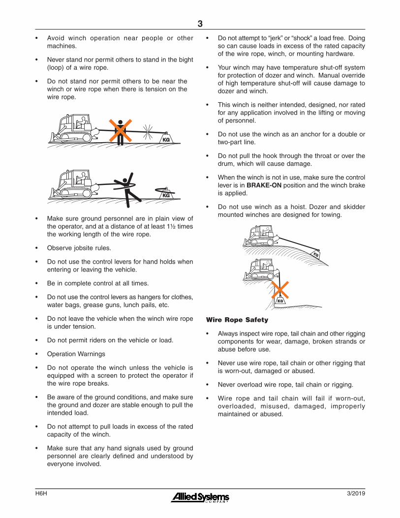
• Avoid winch operation near people or other machines.
• Never stand nor permit others to stand in the bight (loop) of a wire rope.
• Do not stand nor permit others to be near the winch or wire rope when there is tension on the wire rope.
KG
KG
• Make sure ground personnel are in plain view of the operator, and at a distance of at least 1½ times the working length of the wire rope.
• Observe jobsite rules.
• Do not use the control levers for hand holds when entering or leaving the vehicle.
• Be in complete control at all times.
• Do not use the control levers as hangers for clothes, water bags, grease guns, lunch pails, etc.
• Do not leave the vehicle when the winch wire rope is under tension.
• Do not permit riders on the vehicle or load.
• Operation Warnings
• Do not operate the winch unless the vehicle is equipped with a screen to protect the operator if the wire rope breaks.
• Be aware of the ground conditions, and make sure the ground and dozer are stable enough to pull the intended load.
• Do not attempt to pull loads in excess of the rated capacity of the winch.
• Make sure that any hand signals used by ground personnel are clearly defined and understood by everyone involved.
• Do not attempt to “jerk” or “shock” a load free. Doing so can cause loads in excess of the rated capacity of the wire rope, winch, or mounting hardware.
• Your winch may have temperature shut-off system for protection of dozer and winch. Manual override of high temperature shut-off will cause damage to dozer and winch.
• This winch is neither intended, designed, nor rated for any application involved in the lifting or moving of personnel.
• Do not use the winch as an anchor for a double or two-part line.
• Do not pull the hook through the throat or over the drum, which will cause damage.
• When the winch is not in use, make sure the control lever is in BRAKE-ON position and the winch brake is applied.
• Do not use winch as a hoist. Dozer and skidder mounted winches are designed for towing.
Wire Rope Safety
• Always inspect wire rope, tail chain and other rigging components for wear, damage, broken strands or abuse before use.
• Never use wire rope, tail chain or other rigging that is worn-out, damaged or abused.
• Never overload wire rope, tail chain or rigging.
• Wire rope and tail chain will fail if worn-out, overloaded, misused, damaged, improperly maintained or abused.

3/2019H6H
4
WARNINGWire rope or tail chain failure may cause serious injury or death.
Inspect rigging before use and obey all safety warnings.
• Do not terminate wire rope to tail chain by the use of a knot.
• Do not handle wire rope if the hook end is not free. A load could break away, suddenly tensioning the wire rope, resulting in serious injury or death.
• Stay clear of wire rope entry areas (fairlead or arch rollers, winch drum etc).
• Maintain a minimum of three (3) complete wraps of wire rope on the drum for normal operation. It may help to paint the last five wraps of wire rope a contrasting color, to serve as a visual indicator.
• Do not handle wire rope with bare hands. Wear leather gloves at all times.
• Align the dozer with the load to prevent side loading the winch, and to maintain even spooling of the wire rope.
• If applying tension to the wire rope manually during spooling:
x ensure that the operator is winching in slowly, x keep your hands and clothing well clear of any
rollers or the winch drum, x do not maintain tension by letting the wire rope
to slip through your hands, x use a hand-over-hand technique to maintain
tension.
Maintenance Warnings
• Do not permit other people near the control area when you inspect or repair a machine.
• Never inspect, repair, or perform maintenance on a machine that is in motion.
• Inspect the winch before each use:
x Make sure that the controls and instruments operate correctly.
x Report the need for repairs immediately. x Do not work with a damaged or worn wire rope. x Do not use a winch that needs repairs.
x If the wire rope and ferrule must be removed from the drum, make sure the end of the wire rope and ferrule are controlled when the ferrule is released. The end of the wire rope can suddenly move from the drum like a compressed spring when the ferrule is released, and cause an injury.
• Replace any parts only with genuine Allied Winch parts.
• Use only the lubricants listed in the Recommended Oil List, page 8.
• The hydraulic system must be kept clean and free of contamination at all times.
• Do not weld on any part of the winch. Contact Allied Systems if weld repairs are needed.
Hydraulic Hazards
• Wear personal protective equipment, such as gloves and safety glasses, whenever servicing or checking a hydraulic system.
• Assume that all hydraulic hoses and components are pressurized. Relieve all hydraulic pressure before disconnecting any hydraulic line.
• Never try to stop or check for a hydraulic leak with any part of your body; use a piece of cardboard to check for hydraulic leaks.
• Small hydraulic hose leaks are extremely dangerous, and can inject hydraulic oil under the skin, even through gloves.
DANGERInjection hazard.
Infection and gangrene will result when hydraulic oil penetrates the skin. See a doctor immediately to prevent loss of limb or death.
Use a piece of cardboard to check for hydraulic leaks.

H6H
5
3/2019
Unit IdentificationAllied Winch Serial Number Nameplate Data For Dozer Mountings
H6H T 1 B 1001 U47
Vehicle Code See Figure 1
Sequence Number
Winch Model
Hydraulic Operation Type
Gear Ratio (Code #)
T = Standard, Dozer Controls & Pump
Notes: 1. In addition to the serial number plate, the serial number is
stamped on the top left-hand side of the frame.2. If your serial number begins with the letter "K", contact the
factory for parts and service information.
Figure 1 - Dozer or Skidder Identification Codes and Available Gear Ratios
Circled numbers in Figure 1 indicate possible gear ratios.
Figure 2 - Internal Winch Options
H6H = StandardKH6H = Special Design (Contact Factory)
1 = 153:12 = 117:13 = 70:14 = 81:15 = 143:16 = 187:1
Internal OptionsSee Figure 2
FR
EE
SP
OO
L
BR
AK
E-O
FF
OV
ER
WIN
D
2-S
PE
ED
C
ON
TR
OL
B X X X
D X X X X
E X X
U X X
BN X X
DN X X X
EN X
DE X X X
DU X X X
C O D E
UShantui
47 DH17

3/2019H6H
6
When the part number and the next higher assembly is not known:
1. Determine the function and application of the part required. Turn to the illustrated index page immediately behind the front cover, and select the most appropriate area.
2. Use the table of contents at the beginning of each chapter to determine the assembly which would normally contain the part required. Proceed then to locate the part on the assembly breakdown page.
When the part number is not known and the next higher assembly is known:
1. Determine the assembly the required part is used on. Turn to the master index (which immediately follows the illustrated index).
2. Locate the assembly on which the required part
is used, and turn to the page indicated for that assembly. Proceed to locate the part on the assembly breakdown page.
When the part number is known:
Use the numerical index to find the part number. Turn to the page listed and locate the part as indicated by the reference number.
General:
The assembly breakdowns include part numbers, descriptions, quantities required, keys and footnotes to help in selecting the correct parts.
Keys are used to show effective serial numbers for two or more similar assemblies, LH and RH assembly parts, etc. Select the appropriate key, “A,” “B,” “C,” or “D” and the corresponding quantity column to find the required parts.
Indent dots are used to indicate assemblies and sub-parts of assemblies. No dot indicates the major assembly. Part descriptions which are indented with dots are sub-parts of the major assembly shown above.
Quantities shown are for one assembly. Note that when two assemblies are shown, but the quantity of the sub-parts is indicated as three, this means three per assembly - for a total of six. AR means As Required, and NSS indicates Not Sold Separately.
Serial numbers are shown to allow for the most current parts information to be incorporated into the parts manual. See page 6 for serial number information.
Abbreviations
Abbreviations are used both on the winch and in this manual. for example, a manifold may have a port stamped "FS". That port is related to the "freespool" circuit. this abbreviation is also used on pages in this manual that reference this port, or the ports connected to this port. Figure 3 lists the most common abbrevia-tions used in this manual.
Abbreviation Full Name
P Pressure
T Tank
BO Brake Off
FA Filter Outlet
FE Filter Inlet
FS Freespool
HS High Speed
LS Load Sense
PD Pilot Drain
PP Pilot Pressure
PS Pilot Supply
RI Reel In
RO Reel Out
TP Test Port
TS Temperature Switch
Figure 3 - Abbreviations

H6H
7
3/2019
Oil SpecificationsOil Selection
To get the most suitable temperature-viscosity charac-teristics, choose one of the oils listed below.
ManufacturerWinch Case (Gear Train)
Exxon-Mobil (standard) Mobil Trans HD Series
Chevron (optional) Drive Train Fluids HD
Caterpillar (optional) TO-4
Figure 4 - Recommended Oil List
Viscosity GradeOil Operating
Temperature RangeTypical Ambient
Temperature Range
ISO SAE °F °C °F °CVG 22 10W -5 to 140 -20 to 60 -5 to 40 -20 to 4
VG 32 15W 10 to 160 -12 to 71 10 to 55 -20 to 13
VG 46 20 20 to 180 -7 to 82 20 to 70 -7 to 21
VG 68 20 30 to 200 -1 to 93 30 to 90 -1 to 32
VG 100 30 40 to 220 4 to 104 40 to 110 4 to 43
Figure 5 - Viscosity Chart
Factory fill is Exxon-Mobil Trans HD 30.
Note: This winch uses hydraulic fluid from the dozer. See Figure 4 for recommended gear train fluids. Contact the factory if alternate oils are required.
Use of a non-recommended oil may void the warranty.
Oil Capacity
Oil capacity for the H6H winch is 4 gallons (15 liters).

3/2019H6H
8
Ordering PartsWhen ordering replacement parts, give the unit serial number, part number, name of part and quantity required.
For any further information on parts, service or ordering, consult your local winch dealer, or contact Allied Systems Company:
Allied Systems Company 21433 SW Oregon Street
Sherwood, OR 97140 U.S.A.
Phone: 503-625-2560 Fax: 503-625-5132
E-mail: [email protected]
Also see our website, www.alliedsystems.com, where the most current copy of this manual is always available.
NOTE: This publication may be translated to different languages for sole purpose of easy reference in non-English speaking locations. Should there be differences in interpretations to the text, please refer to the English language edition published by Allied Systems Company as the controlling document.
H6H
9
3/2019
Nameplate & Decals
3
VIEW A-A
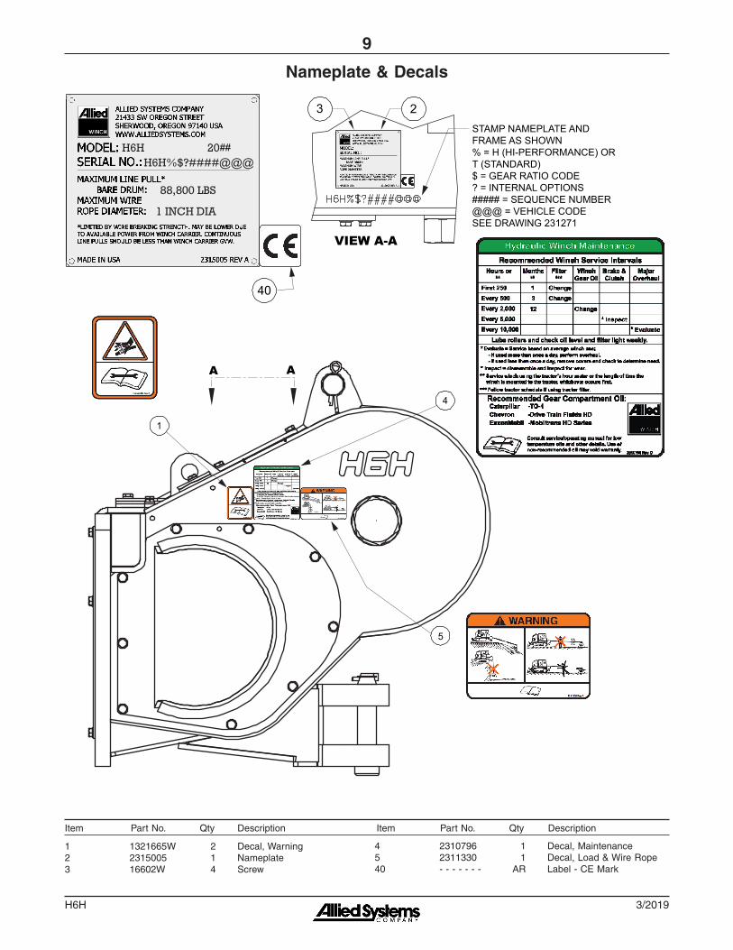
2STAMP NAMEPLATE AND FRAME AS SHOWN% = H (HI-PERFORMANCE) OR T (STANDARD)$ = GEAR RATIO CODE? = INTERNAL OPTIONS##### = SEQUENCE NUMBER@@@ = VEHICLE CODESEE DRAWING 231271
1
4
5
A A
40
##
1 1321665W 2 Decal, Warning2 2315005 1 Nameplate3 16602W 4 Screw
4 2310796 1 Decal, Maintenance5 2311330 1 Decal, Load & Wire Rope40 - - - - - - - AR Label - CE Mark
Item Part No. Qty Description Item Part No. Qty Description

3/2019H6H
10
Intentionally Blank

H6H
11
3/2019
Section 1
Frames and Covers

3/2019H6H
12
Frame/CoversShantui DH17 (H6HT**U47)
Page 1 of 2
2.6
2.5
2.6
2.2
2.1
1 3.14
3.16
3.9
3.10
2.42.3
3.6
3.16 3.15
3.113.12
3.13
3.13.2
3.163.15,
3.163.14
3.153.16
13.113.8
13.4
13.6
5.2
13.5
13.113.8
18.218.1
13.413.2
3.153.16
1
1
Shantui mounting/installation parts were customer-supplied

H6H
13
3/2019
Frame/CoversShantui DH17 (H6HT**U47)
Page 2 of 2
1 ---------- 1 Frame, H6H2.1 95959W 1 Pin, Drawbar2.2 2303221W 1 Pin, Retaining2.3 2312580 1 Rod, Tie2.4 15272W 2 Pin2.5 15290W 1 Fitting2.6 15315W 2 Fitting3.1 2312048 1 Cover, Top RH3.2 2312045 1 Gasket, Top RH3.6 2316162 1 Cover, LH3.9 151589W 1 Cover, Freespool3.10 151646W 1 Gasket, Freespool3.11 21420W 1 Plug, Breather3.12 2300962W 1 Cap, Breather
3.13 15319W 1 Fitting3.14 2312486 10 Capscrew3.15 293645W 15 Capscrew3.16 296422W 25 Washer5.2 2312208 1 Gasket, Hose Seal13.1 293645W 10 Capscrew13.2 2312117 1 Cover13.4 2312119 6 Spacer13.5 2312046 1 Cover, Front13.6 2312006 1 Clamp, Top13.8 296422W 10 Washer18.1 2312850 1 Cover, Top LH18.2 2312849 1 Cover, Top
Item Part No. Qty Description Item Part No. Qty Description

3/2019H6H
14
Mounting/Installation PartsShantui DH17 (H6HT**U47)
Note:Mounting/installation parts are customer-supplied for this model.

H6H
15
3/2019
Section 2
Gear Shaft/Train

3/2019H6H
16
Motor Shaft GroupPage 1 of 2
1
4
3
4
4
4
4
LH COVER (REF)
WINCH FRAME (REF)
5
67
8
9
1011
12
13
13
14
15
16
17
18
19
8
20
2311819 list2316468 dwg
H6H
17
3/2019
2311819 Motor Shaft Group1 2311857 1 . Cover, Bearing3 2312488 7 . Capscrew4 296422W 19 . Washer5 2312487 6 . Capscrew6 293645W 1 . Capscrew7 *c 2316491 1 . Bracket, Motor Support7 *d 2312036 1 . Bracket, Motor Support8 292656W 3 . Nut9 2312018 1 . Plate, Manifold Bracket10 2312061 AR . Shim .02011 2312059 AR . Shim .00512 2312060 AR . Shim .00713 *a 203564 2 . O-Ring
14 2311917 2 . Plate, Clamp15 2311918 1 . Plate, Clamp16 *b 2300668W 1 . Cup, Bearing17 *b 2300669W 1 . Cone, Bearing18 - - - - 1 . Assy, Motor Shaft 19 293647W 1 . Capscrew20 2305130W 1 . Nut, Bracket Support
*a Included in Motor, Reducer & Brake Assembly Rebuild Kit 2314659 *b Included in Intermediate/Drum Shaft & Brake Assembly Rebuild Kit 2314660 *c First Used S/N 1714 *d Last Used S/N 1713 *e See page 18 for details.
Motor Shaft GroupPage 2 of 2
Item Part No. Qty Description Item Part No. Qty Description
3/2019H6H
18
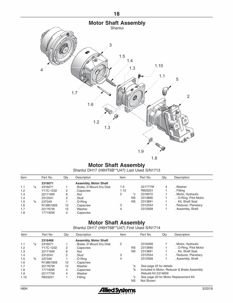
Motor Shaft AssemblyShantui DH17 (H6HT6B**U47) First Used S/N1714
Motor Shaft AssemblyShantui DH17 (H6HT6B**U47) Last Used S/N1713
Motor Shaft AssemblyShantui
3
2
4
5
1.6
1.7
1.5
1.2
1.4
1.3
1.3
1.1
1.81.9
1.10
2316468 Assembly, Motor Shaft1.1 *a 2316071 1 . Brake, D Mount Dry Disk1.2 Y17C-1232 2 . Capscrew1.3 221716W 6 . Nut1.4 2312041 2 . Stud1.5 *b 237349 1 . O-Ring1.6 R13801826 12 . Capscrew1.7 221767W 12 . Washer1.8 177192W 4 . Capscrew1.9 221777W 4 . Washer1.10 R833251 1 . Fitting
2316071 Assembly, Motor Shaft1.1 *a 2316071 1 . Brake, D Mount Dry Disk1.2 Y17C-1232 2 . Capscrew1.3 221716W 6 . Nut1.4 2312041 2 . Stud1.5 *b 237349 1 . O-Ring1.6 R13801826 12 . Capscrew1.7 221767W 12 . Washer1.8 177192W 4 . Capscrew
2 2316469 1 . Motor, Hydraulic NS 2313890 1 . . O-Ring, Pilot Motor NS 2313891 1 . . Kit, Shaft Seal3 2312554 1 . Reducer, Planetary4 2312928 1 . Assembly, Shaft
*a See page 25 for details *b Included in Motor, Reducer & Brake Assembly Rebuild Kit 2314659 *c See page 20 for Motor Replacement Kit NS Not Shown
1.9 221777W 4 . Washer1.10 R833251 1 . Fitting2 *c 2316072 1 . Motor, Hydraulic NS 2313890 1 . . O-Ring, Pilot Motor NS 2313891 1 . . Kit, Shaft Seal3 2312554 1 . Reducer, Planetary4 2312928 1 . Assembly, Shaft
Item Part No. Qty Description Item Part No. Qty Description
Item Part No. Qty Description Item Part No. Qty Description

H6H
19
3/2019
Intentionally Blank

3/2019H6H
20
1 *a - - - - - - - 1 Motor - Hyd; Danfoss H1B2 *a - - - - - - - 2 Tube Assy - Motor A3 *a - - - - - - - 6 Tube Assy - Motor B4 592255 2 Kit, Split Flange
*a Refer to the chart below to determine replacement parts for cancelled motors
Item Part No. Qty Description Item Part No. Qty Description
Motor Replacement KitPage 1 of 2
OVERWIND UNDERWIND
3
1
2
4
1
3
2
4
WINCH MODEL
KIT PART NUMBER:
OVERWIND/UNDERWIND
CANCELLED MOTOR:
ITEM 1 (CURRENT MOTOR):
ITEM 2 (TUBE A):
ITEM 3 (TUBE B):
H6HT6B**U47 2316943 O 2316072 2316469 2316108 2316109
2316944 U 2316072 2316469 2316714 2316715
Notes:Use this chart to determine which H1B motor replaces the cancelled 51V motor.
Be sure to note whether your motor is overwind or underwind to get the appropriate kit. Each kit contains all the components needed to convert your winch to the current motor.
This model might not need the serial number break, and therefore not this
motor replacement info
Overwind
Underwind

H6H
21
3/2019
Motor Replacement KitPage 2 of 2
CONVERSION TO H1B FROM 51V MOTOR FOR H6H:
1. REMOVE MATERIAL FROM FRAME AS SEEN IN DETAIL A TO ALLOW FOR FIT OF NEW H1B MOTOR. MORE MATERIAL MAY BE REMOVED IF NECESSARY FOR FIT.
2. MATERIAL MAY BE REMOVED FROM COVER TO ALLOW FOR FIT OF MOTOR AS NECESSARY.
DETAIL A
(.6)
(2.4)
(8.2)
A
H1B MOTOR(NEW)
ALTERNATECASE DRAIN
X1 PRESSURE PORT (BOTH SIDES)
GAUGE PORT(BOTH SIDES)
CASE DRAIN
51V MOTOR(LEGACY)
X1 PRESSURE PORT
GAUGE PORT(BOTH SIDES)
CASE DRAIN
ALTERNATECASE DRAIN
Conversion to H1B from 51V motor for H6H:1. Remove material from the winch frame as
seen in Detail A to allow the new H1B motor to fit. More material may be removed if necessary for fit.
2. Material may be removed from the cover as necessary to allow the new motor to fit.

3/2019H6H
22
1
1516
17
5
11
2
1312
67
4, 8
10, 8
9
2119
18
20
14
3Shaft Assembly
BRAKE-OFF
2313026 Assy, BRAKE-OFF Shaft1 2311855 1 . Housing, Clutch2 2311856 1 . Shaft, Clutch3 231439 1 . Fitting4 2312039 1 . Piston, Clutch5 2311683 1 . Ring, Snap6 2312442 1 . Ring, Thrust7 2311655 1 . Brg, Thrust Needle Roller8 86585W 2 . O-Ring9 87287W 1 . O-Ring10 2311880 1 . Ring, Seal11 *a 2311903 1 . Assy, Clutch12 239147W 1 . Pin13 2303992W 1 . Spring14 R13811617 1 . Capscrew
15 2311684 1 . Ring, Snap16 137153W 1 . Cup, Roller Bearing17 137155W 1 . Cone, Roller Bearing18 2311869 1 . Shim .06219 230407W 1 . Bearing20 2311687 1 . Shim .06221 *b 2312977 1 . Gear, Spider21 *c 2311905 1 . Gear, Spider
*a See page 23 for details *b Gear ratios 2 & 5 *c Gear ratios 1 & 6
Item Part No. Qty Description Item Part No. Qty Description

H6H
23
3/2019
Clutch Assembly
2311903 Assy, Clutch1 2311904 1 . Hub, Clutch2 2311907 1 . Plate, Clutch3 2312029 1 . Retainer, Spring4 328715W 7 . Disc, Friction5 261542W 6 . Plate, Separator
6 2311906 1 . Plate, Pressure7 296420W 6 . Washer8 293628W 6 . Capscrew9 2311251 3 . Spring, Belleville10 222713W 3 . Pin
1
5
2
6
7
8
10
4
9 3
Item Part No. Qty Description Item Part No. Qty Description

3/2019H6H
24
Dry Disc BrakePage 1 of 2

H6H
25
3/2019
2312155 Brake, D Mount Dry Disc 1 NSS 1 . Retaining Ring 2 NSS 1 . Retaining Ring 3 *b NSS 1 . Bearing 4 *a,*b NSS 1 . Oil Seal 5 NSS 1 . Cover Plate 6 NSS 1 . Spline Shaft Assy 7 NSS 4 . Bolt 8 *d NSS 1 . Primary Disc 9 *d NSS 8 . Rotor Disc 10 *d NSS 7 . Stator Disc 11 *a,*b,*c,*d NSS 2 . Case Gasket 12 NSS 4 . Capscrew 13 NSS 4 . Dowel Pins 14 NSS 1 . Spring Plate 15 *c NSS 10 . Spring, Red 16 NSS 1 . Piston 17 *a NSS 1 . Backup Ring 18 *a NSS 1 . O-Ring 19 *a NSS 1 . Backup Ring 20 *a NSS 1 . O-Ring
21 *b NSS 1 . Bearing 22 NSS 1 . Pressure Plate 23 NSS 4 . Capscrew
*a Included in O-Ring Repair Kit 2312302; O-Ring Repair Kit 2312302 is included in Motor, Reducer & Brake Assembly Rebuild Kit 2314659 *b Included in Bearing Repair Kit 2312303; Bearing Repair Kit 2312303 is included in Intermediate/Drum Shaft & Brake Assembly Rebuild Kit 2314660 *c Included in Spring Repair Kit 250850; Spring Repair Kit 250850 is included in Intermediate/Drum Shaft & Brake Assembly Rebuild Kit 2314660 *d Included in Lining Repair Kit 250847; Lining Repair Kit 250847 is included in Intermediate/Drum Shaft & Brake Assembly Rebuild Kit 2314660 NSS Not Sold Separately
Dry Disc BrakePage 2 of 2
Item Part No. Qty Description Item Part No. Qty Description

3/2019H6H
26
20.6
20.7
20.3
20.8, 20.9, 20.10
20.420.5
20.5
20.4
20.2
20.1
21.1
Intermediate Gear ShaftWithout Freespool
20.1 95972W 1 Shaft20.2 95973W 1 Gear20.3 280262W 1 Retainer, Bearing20.4 *a 30059W 2 Cup, Roller Bearing20.5 *a 30080W 2 Cone, Roller Bearing20.6 2312487 6 Capscrew20.7 296422W 6 Washer20.8 149541W AR Shim .00520.9 149542W AR Shim .007
20.10 149543W AR Shim .02021.1 *b 96024W 1 Gear21.1 *c 2314411 1 Gear
*a Included in Intermediate/Drum Shaft & Brake Assembly Rebuild Kit 2314660 *b Gear ratios 1 & 6 *c Gear ratios 2 & 5 AR As Required. Refer to Service Manual 599040W for more information.
Item Part No. Qty Description Item Part No. Qty Description

H6H
27
3/2019
Intermediate Gear ShaftWith FREESPOOL
1
23
4
45
7
8
910
11
12
13
14
1516
17
1718
18
21
8A
See Frames & CoversFor Part Numbers
20
1 *a 2311894 1 Shaft, Freespool2 2305097W 1 Piston, Freespool3 2305099W 1 Shifter Fork, Freespool4 *b 15862W 2 O-Ring5 *b 212380 1 O-Ring7 2305096W 1 Spring8 *c 283434W 1 Assy, Intermediate Gear8 *d 2303036 1 Assy, Intermediate Gear8A 283432W 1 . Bushing9 2302624W 1 Piston, Freespool Adjust10 *b 159940W 1 O-Ring11 2302625W 1 Housing, Freespool Adjust12 2305956W 1 Shaft, Intermediate13 2312280 1 Gear, Pinion
14 2312269 1 Clutch, Dental15 2304803W 1 Screw16 221717W 1 Nut, Hex17 *b 2302311W 2 Cone, Bearing18 *b 30059W 2 Cup, Bearing20 2312488 6 Capscrew21 296422W 6 Washer, Hard
*a Apply Threadlock 318702W to threads *b Included in Intermediate/Drum Shaft & Brake Assembly Rebuild Kit 2314660 *c Gear ratios 1 & 6 *d Gear ratios 2 & 5
Item Part No. Qty Description Item Part No. Qty Description

3/2019H6H
28
Drum Shaft
1 141674W 1 Adapter2 53559W 10 Thimble, Tapered3 *b 2310093 2 Bearing, Roller4 221577W 8 Capscrew5 *b 15158W 9 Washer6 95978W 1 Retainer7 *a 172808W 1 Spacer8 15881W 1 O-Ring9 *b 44547W 1 Seal, Oil10 *b 133927W 1 Ring, Piston Seal11 *b 90263W 1 O-Ring12 175648W AR Shim, .02013 175647W AR Shim, .00714 175646W AR Shim, .00515 2301783W 1 Keeper, Ferrule16 16829W 1 Capscrew
17 221771W 8 Hard Washer18 2310891 10 Capscrew19 141671W 1 Seal, Oil20 2312064 1 Shaft, Drum21 95977W 1 Gear, Drum22 296422W 6 Washer23 2312486 6 Capscrew24 172810W 1 Retainer25 *a 2312099 2 Nut26 2313730 1 Drum, H6H27 Y433070.45 1 Fitting
*a Requires Sealant 358674W *b Included in Intermediate/Drum Shaft & Brake Assembly Rebuild Kit 2314660
Item Part No. Qty Description Item Part No. Qty Description
H6H
29
3/2019
Section 3
Hydraulic/Electrical Components
3/2019H6H
30
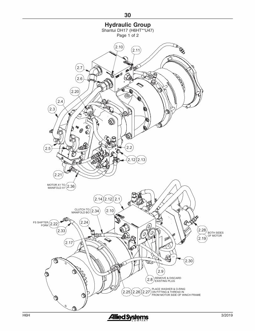
Hydraulic GroupShantui DH17 (H6HT**U47)
Page 1 of 2
CONTROL MANIFOLD DETAIL
2.242.18
2.23 2.15
2.35
2.18
2.31
2.24 2.18
2.34
2.32
2.282.16 FS, BO & X1
TO FS BULKHEAD
TO BO CLUTCH
TO BRAKE
PD TO MOTOR CASE DRAIN
2.2
2.12 2.13
2.36
2.21
2.3
2.4
2.7
2.6
2.102.11
2.22
2.17
2.24
2.34 2.10
2.12.122.14
2.8
2.30
2.9
2.25 2.26 2.27
2.28
2.19 BOTH SIDES OF MOTOR
REMOVE & DISCARD EXISTING PLUG
CLUTCH TO MANIFOLD BO
FS SHIFTER FORK
PLACE WASHER & O-RING ON FITTING & THREAD IN FROM MOTOR SIDE OF WINCH FRAME
2.33
MOTOR X1 TO MANIFOLD X1
2.20
2.29
2.5
2.242.22 RI RO
X1

H6H
31
3/2019
Hydraulic GroupShantui DH17 (H6HT**U47)
Page 2 of 2
2.1 *a 2312941 1 Counterbalance Relief Manifold Assy2.2 *b 2311770 1 Manifold Assy2.3 2316108 1 Tube Assy - Motor A2.4 2316109 1 Tube Assy - Motor B2.5 592255 2 Kit, Split Flange2.6 2313948 1 Fitting2.7 R833218 1 Fitting2.8 2307904W 1 Switch - Temperature2.9 229389 2 Fitting2.10 229383 2 Fitting2.11 235387 1 Fitting2.12 Y09C-M1025 4 Capscrew2.13 296420W 2 Hard Washer2.14 15176W 2 Flat Washer2.15 231465 1 Fitting2.16 R833400 3 Fitting2.17 236855 1 Fitting2.18 R833251 3 Fitting2.19 R833253 2 Fitting
2.20 R833260 1 Fitting2.21 R833103 1 Fitting2.22 231439 2 Fitting2.23 231822 1 Fitting2.24 232984 4 Fitting2.25 R834100 1 Fitting2.26 15178W 1 Flat Washer2.27 211564 1 O-Ring2.28 2307625W 5 Fitting2.29 R14040 1 Coupler, Male2.30 2312628 1 Clamp2.31 2312353 1 Hose Assy2.32 2312350 1 Hose Assy2.33 2312212 1 Hose Assy2.34 2312351 1 Hose Assy2.35 R12104 1 Hose Assy2.36 2313639 1 Hose Assy
*a See page 32 for details *b See page 33 for details
Item Part No. Qty Description Item Part No. Qty Description
CONTROL MANIFOLD DETAIL
2.242.18
2.23 2.15
2.35
2.18
2.31
2.24 2.18
2.34
2.32
2.282.16 FS, BO & X1
TO FS BULKHEAD
TO BO CLUTCH
TO BRAKE
PD TO MOTOR CASE DRAIN
2.2
2.12 2.13
2.36
2.21
2.3
2.4
2.7
2.6
2.102.11
2.22
2.17
2.24
2.34 2.10
2.12.122.14
2.8
2.30
2.9
2.25 2.26 2.27
2.28
2.19 BOTH SIDES OF MOTOR
REMOVE & DISCARD EXISTING PLUG
CLUTCH TO MANIFOLD BO
FS SHIFTER FORK
PLACE WASHER & O-RING ON FITTING & THREAD IN FROM MOTOR SIDE OF WINCH FRAME
2.33
MOTOR X1 TO MANIFOLD X1
2.20
2.29
2.5
2.242.22 RI RO
X1

3/2019H6H
32
Counterbalance Relief Manifold Assy
2312941 Assembly - Manifold, Counterbalance Relief1 2312940 1 . Manifold - Body, Counterbalance Relief2 2312068 1 . Valve, Counterbalance 243815 1 . . Seal Kit3 2307438W 2 . Relief Valve 259258 1 . . Seal Kit
4 2310181 1 . Plug5 235387 3 . Fitting6 229345 1 . Fitting7 227949 1 . Fitting
Item Part No. Qty Description Item Part No. Qty Description
1
5 7
63
25
4

H6H
33
3/2019
Control Manifold Assy
2311770 1 Assy, Control Manifold1 2311771 1 . Body, Control Manifold2 2311592 1 . Valve, Directional 252566 1 . . Kit, Seal3 2312073 2 . Valve, Cartridge 2314106 1 . . Base, Valve Cartridge 2313984 1 . . Coil 2312111 1 . . Kit, Seal
4 2312074 1 . Valve, Shuttle 2312112 1 . . Seals, O-Ring
2
4
3
3
1
Item Part No. Qty Description Item Part No. Qty Description

3/2019H6H
34
Section 4
Optional Equipment
H6H
35
3/2019
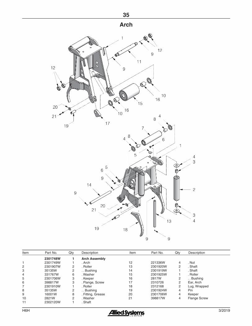
2301748W 1 Arch Assembly1 2301749W 1 . Arch2 2301907W 2 . Roller3 35135W 2 . . Bushing4 331767W 6 . Washer5 2301706W 3 . Keeper6 398817W 3 . Flange, Screw7 2301910W 1 . Roller8 35135W 2 . . Bushing9 16001W 8 . Fitting, Grease10 2821W 2 . Washer11 2302120W 1 . Shaft
Arch
12 221336W 4 . Nut13 2301920W 2 . Shaft14 2301919W 1 . Shaft15 2301925W 1 . Roller16 2817W 2 . . Bushing17 2310726 2 Ear, Arch18 2312168 2 Lug, Wrapped19 2301924W 4 Pin20 2301706W 4 Keeper21 398817W 4 Flange Screw
Item Part No. Qty Description Item Part No. Qty Description

3/2019H6H
36
Fairlead3-Roller, Last Used S/N1609
2301731W Fairlead Assembly, 3-Roller1 2301727W 1 . Roller2 2570W 2 . . Bushing3 2301722W 1 . Shaft4 2301706W 3 . Keeper5 33394W 6 . Washer6 16001W 6 . Fitting, Grease7 398817W 3 . Screw, Flange8 2301718W 1 . Fairlead9 2301726W 2 . Roller
10 2570W 4 . . Bushing11 2301721W 2 . Shaft12 226374W 2 Bracket13 93878W AR Shim14 18669W 4 Capscrew15 15166W 4 Washer16 15272W 2 Pin, Cotter17 2312437 2 Spacer18 2312580 1 Bar, Tie
Item Part No. Qty Description Item Part No. Qty Description
H6H
37
3/2019
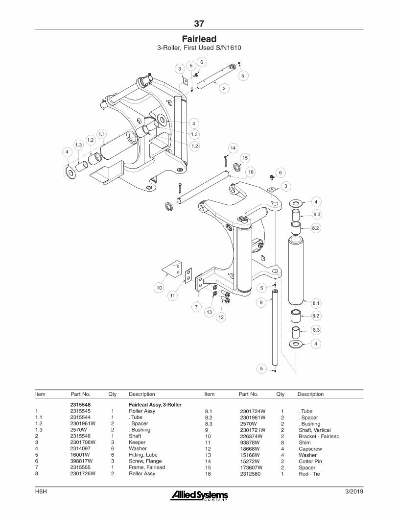
Fairlead3-Roller, First Used S/N1610
2315548 Fairlead Assy, 3-Roller1 2315545 1 Roller Assy1.1 2315544 1 . Tube1.2 2301961W 2 . Spacer1.3 2570W 2 . Bushing2 2315546 1 Shaft3 2301706W 3 Keeper4 2314097 6 Washer5 16001W 6 Fitting, Lube6 398817W 3 Screw, Flange7 2315555 1 Frame, Fairlead8 2301726W 2 Roller Assy
8.1 2301724W 1 . Tube8.2 2301961W 2 . Spacer8.3 2570W 2 . Bushing9 2301721W 2 Shaft, Vertical10 226374W 2 Bracket - Fairlead11 93878W 8 Shim12 18668W 4 Capscrew13 15166W 4 Washer14 15272W 2 Cotter Pin15 173607W 2 Spacer16 2312580 1 Rod - Tie
1011
15
6
3
16
14
713
12
5
4
8.3
8.2
8.1
5
9
2
53 5
6
1.2
1.3
8.2
8.3
4
4
41.3
1.21.1
Item Part No. Qty Description Item Part No. Qty Description
3/2019H6H
38
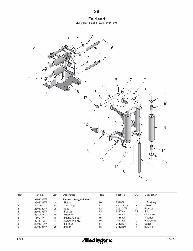
Fairlead4-Roller, Last Used S/N1609
2301732W Fairlead Assy, 4-Roller1 2301727W 2 . Roller2 2570W 4 . . Bushing3 2301722W 2 . Shaft4 2301706W 4 . Keeper5 33394W 8 . Washer6 16001W 8 . Fitting, Grease7 398817W 4 . Screw, Flange8 2301718W 1 . Fairlead9 2301726W 2 . Roller
10 2570W 4 . . Bushing11 2301721W 2 . Shaft12 226374W 2 Bracket13 93878W AR Shim14 18668W 4 Capscrew15 15166W 4 Washer16 15272W 2 Pin, Cotter17 2312437 2 Spacer18 2312580 1 Bar, Tie
Item Part No. Qty Description Item Part No. Qty Description

H6H
39
3/2019
Fairlead4-Roller, Wide, First Used S/N1610
2315549 Fairlead Assy, 4-Roller1 2315545 2 Assy, Roller1.1 2315544 1 . Tube1.2 2301961W 2 . Spacer1.3 2570W 2 . Bushing2 2315546 2 Shaft3 2301706W 4 Keeper4 2314097 8 Washer5 16001W 8 Fitting, Lube6 398817W 4 Screw, Flange7 2315555 1 Frame, Fairlead8 2301726W 2 Assy, Roller
8.1 2315544 1 . Tube8.2 2301961W 2 . Spacer8.3 2570W 2 . Bushing9 2301721W 2 Shaft, Vertical10 226374W 2 Bracket, Fairlead11 93878W 8 Shim12 18668W 4 Capscrew13 15166W 4 Washer14 15272W 2 Cotter Pin15 173607W 2 Spacer16 2312580 1 Bar, Tie
1011
1312
4
4
5
88
8.3
8.3
8.2
8.2
8.15
63
7
16
14
15
9
4
1
1.31.2
1.13
5
1
7
1.21.3
4
526
Item Part No. Qty Description Item Part No. Qty Description
3/2019H6H
40
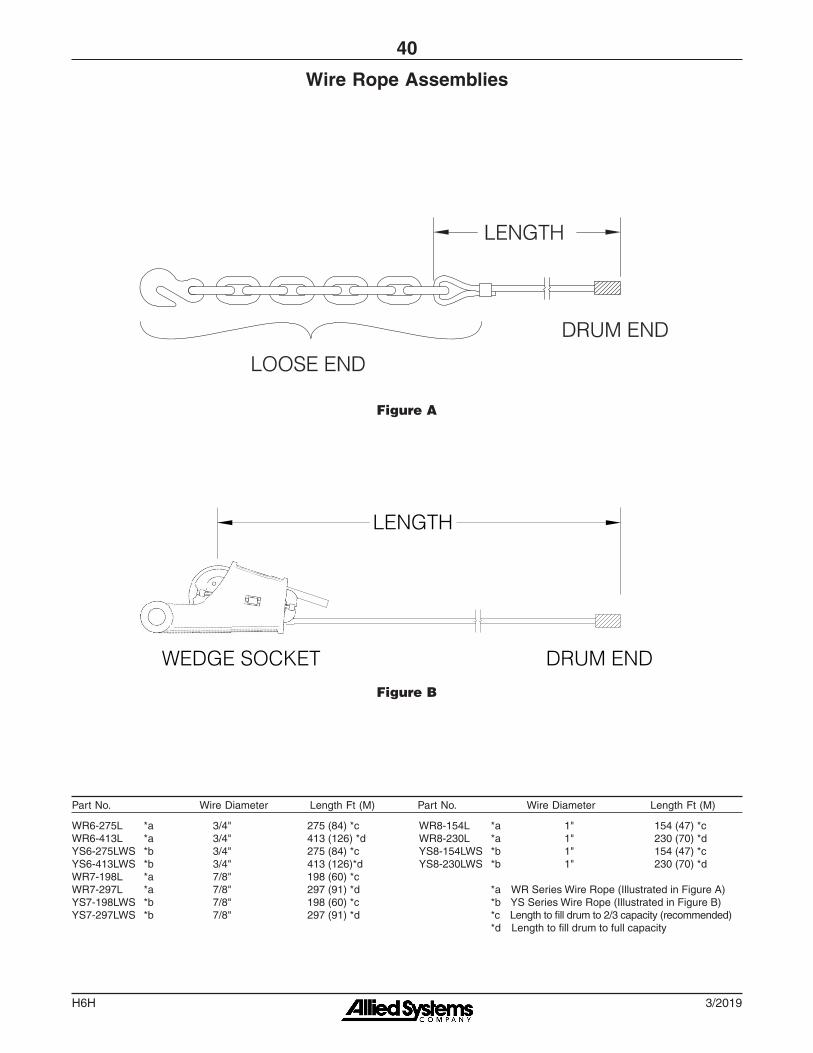
Wire Rope Assemblies
WR6-275L *a 3/4" 275 (84) *cWR6-413L *a 3/4" 413 (126) *dYS6-275LWS *b 3/4" 275 (84) *cYS6-413LWS *b 3/4" 413 (126)*dWR7-198L *a 7/8" 198 (60) *cWR7-297L *a 7/8" 297 (91) *dYS7-198LWS *b 7/8" 198 (60) *cYS7-297LWS *b 7/8" 297 (91) *d
WR8-154L *a 1" 154 (47) *cWR8-230L *a 1" 230 (70) *dYS8-154LWS *b 1" 154 (47) *cYS8-230LWS *b 1" 230 (70) *d
*a WR Series Wire Rope (Illustrated in Figure A) *b YS Series Wire Rope (Illustrated in Figure B) *c Length to fill drum to 2/3 capacity (recommended) *d Length to fill drum to full capacity
WEDGE SOCKET DRUM END
LENGTH
Figure B
LENGTH
LOOSE END
DRUM END
Figure A
Part No. Wire Diameter Length Ft (M) Part No. Wire Diameter Length Ft (M)
H6H
41
3/2019
Section 5
Service Kits

3/2019H6H
42
Recommended Winch Service Intervals and Kits
Following the service schedule recommended here to help keep dozer winch downtime to a minimum, optimize winch operation, and extend the life of your investment.
See Table 1 for recommended service intervals, and Table 2 for recommended service kits.
Table 1 Recommended Winch Service Intervals
Table 2 Routine Maintenance Kits
Service Kits for H6H Winches
Service Description Kit DescriptionWinch Serial
Number
Kit Part# for Hi-
Performance (H) Winches
Kit Part# for Standard (T)
Winches
Filter change Filter kit AllRefer to dozer operator and service
manuals
Complete oil change (every 1,000 hours)
N/A AllCheck our website for current
operator's and service manuals for appropriate oils
Clutch and brake overhaul (every 5,000 hours)
Motor, reducer & brake assembly rebuild kit
All 2314659
Major overhaul (every 10,000 hours)
Intermediate/drum shaft & brake assembly rebuild kit
All 2314660
Hydraulic Winch Maintenance
Recommended Winch Service Intervals
Hours or ** Months ** Filter *** Winch Gear Oil Brake & Clutch Major Overhaul
First 250 1 Change
Every 500 3 Change
Every 2,000 12 Change
Every 5,000 *Inspect
Every 10,000 *Evaluate
Lube rollers and check oil level and filter light every week.
* Evaluate = Service based on average winch use; If used more than once a day, perform an overhaul. If used less than once a day, remove covers and check to determine need.* Inspect = Disassemble and inspect for wear.** Service winch using the dozer's hour meter or the length of time the winch is mounted to the dozer, whichever occurs first.*** Follow dozer schedule if using dozer filter.
Recommended Gear Compartment Oil
Chevron Drive Train Fluids HD Consult service/operating manual for low temperature oils and other details. Use of non-recommended oil may void the warranty.ExxonMobil Mobiltrans HD Series

H6H
43
3/2019
Motor, Reducer & Brake Assembly Rebuild Kit: 2314659Page 1 of 2
2
3/2019H6H
44
6
7
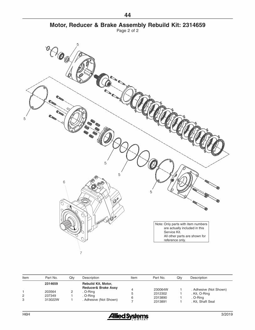
Motor, Reducer & Brake Assembly Rebuild Kit: 2314659Page 2 of 2
Note: Only parts with item numbers are actually included in this Service Kit. All other parts are shown for reference only.
2314659 Rebuild Kit, Motor, Reducer& Brake Assy1 203564 2 . O-Ring2 237349 1 . O-Ring3 313022W 1 . Adhesive (Not Shown)
4 230064W 1 . Adhesive (Not Shown)5 2312302 1 . Kit, O-Ring6 2313890 1 . O-Ring7 2313891 1 . Kit, Shaft Seal
Item Part No. Qty Description Item Part No. Qty Description
H6H
45
3/2019
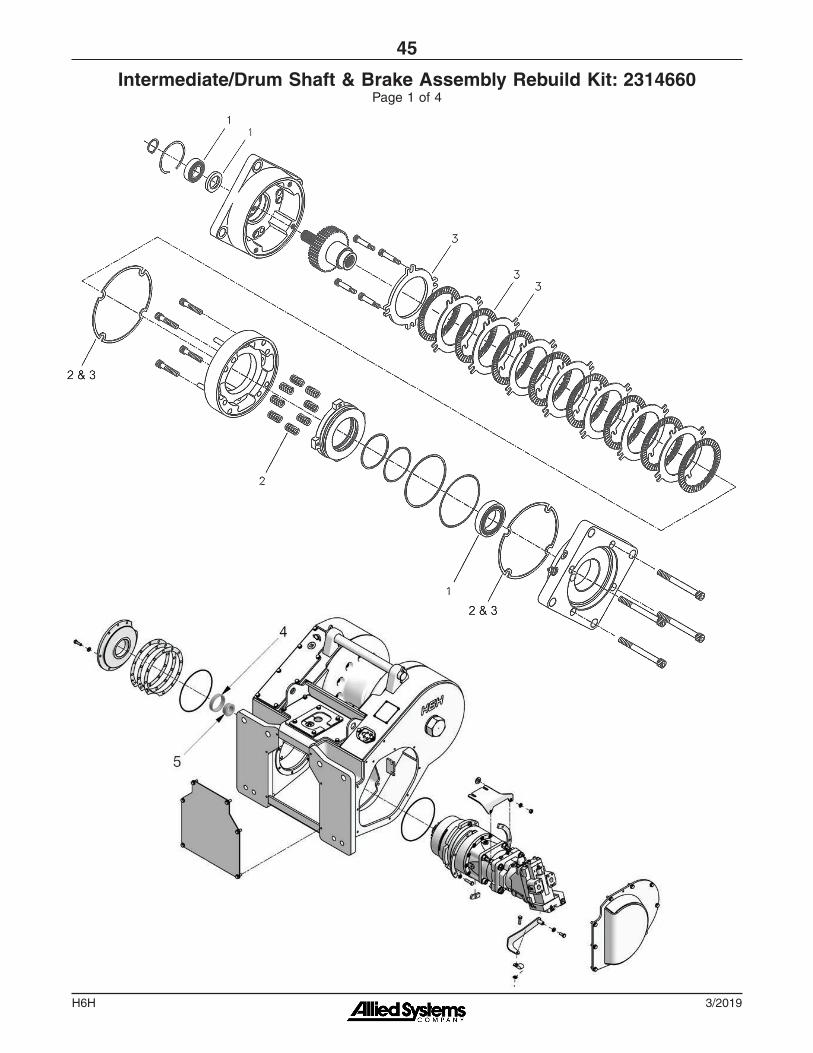
Intermediate/Drum Shaft & Brake Assembly Rebuild Kit: 2314660Page 1 of 4

3/2019H6H
46
Intermediate/Drum Shaft & Brake Assembly Rebuild Kit: 2314660Page 2 of 4
Without FREESPOOL

H6H
47
3/2019
Intermediate/Drum Shaft & Brake Assembly Rebuild Kit: 2314660Page 3 of 4
With FREESPOOL

3/2019H6H
48
Intermediate/Drum Shaft & Brake Assembly Rebuild Kit: 2314660Page 4 of 4
Note: Only parts with item numbers are actually included in this Service Kit. All other parts are shown for reference only.
2314660 Rebuild Kit, Intermediate/ Drum Shaft & Brake Assy1 2312303 1 . Repair Kit, Bearing2 250850 1 . Repair Kit, Spring3 250847 1 . Repair Kit, Lining4 2300668W 1 . Cup, Bearing5 2300669W 1 . Cone, Bearing6 30059W 2 . Cup, Bearing7 30080W 2 . Cone, Bearing8 159940W 1 . O-Ring9 2302311W 2 . Cone, Bearing
10 30059W 2 . Cup, Bearing11 15862W 2 . O-Ring12 212380 1 . O-Ring13 230406W 2 . Bearing, Roller14 15881W 1 . O-Ring15 44547W 1 . Seal, Oil16 133927W 1 . Ring, Piston Seal17 90263W 1 . O-Ring
Item Part No. Qty Description Item Part No. Qty Description

H6H
49
3/2019
Section 6
Recommended Service Parts
3/2019H6H
50
H6H Hydraulic Winch Recommended Service Parts
The following pages list some of the service parts and kits that are available for your Allied H6H Winch.
Page 51 lists gaskets and seals. Keep these parts in stock at all times for regular maintenance.
Page 51 and page 52 contain kits for 5,000 hour and 10,000 hour scheduled maintenance. Order these kits in preparation for these intervals. Each kit includes all parts listed in the table. Order parts from the table based on your winch.
Page 52 is a list of wire rope assemblies. Order parts as required and as relevant for your installation.
Page 53 contains a list of spare parts. Order parts or kits as required and as relevant for your installa-tion.
Page 53 contains lists of operator controls components. Order parts or kits as required and as rel-evant for your installation.
Page 54 contains lists of tool kits and diagnostic tools, which are useful when you install, maintain and service your winches.
Note: Allied Winch parts manuals are available for no charge download at http://www.alliedsystems.com/pubs/pubs.htm.

H6H
51
3/2019
Motor, Reducer & Brake Assembly Rebuild Kit, P/N: 2314659
Applies to: AllService Interval: Every 5,000 Hours
Allied P/N DescriptionQty in
KitSee Parts
Manual PageOrder Qty
2314659 Rebuild Kit, Motor, Reducer & Brake Assy
203564 . O-Ring 2 Motor Shaft Group
237349 . O-Ring 1 Motor Shaft Assembly
313022W . Adhesive 1 Motor Shaft Assembly
230064W . Adhesive 1 Motor Shaft Assembly
2312302 . Kit, O-Ring 1 Brake, Dry Disc
2313890 . O-Ring 1 Hydraulic Motor
2313891 . Kit, Shaft Seal 1 Hydraulic Motor
Gaskets & Seals Order as Required
Applies to: H6H Standard Winch mounted on Shantui DH17 (U47)
Allied P/N DescriptionQty on Winch
See Parts Manual Page
Order Qty
2312045 Gasket, Top Right-Hand 1 Frames/Covers
151646W Gasket, Freespool 1 Frames/Covers
2312009 Seal, Top 1 Frames/Covers
2312208 Gasket, Hose Seal 1 Frames/Covers
252566 Seal Kit, Directional Valve (P/N 2311592) 1 Control Manifold Assy
2312111 Seal Kit, Cartridge Valve (P/N 2312073) 2 Control Manifold Assy
2312112 Seal Kit, Shuttle Valve (P/N 2312074) 1 Control Manifold Assy
243815 Seal Kit, Cavity Plug (P/N 258473) 1 CBR Manifold Assy
251170 Seal Kit, Cavity Plug (P/N 256462) 2 CBR Manifold Assy

3/2019H6H
52
Wire Rope Assemblies Order as Required
Applies to: All
Allied P/N Description Length Will Fill Drum To:Order Qty
WR6-275L Wire Rope Assy, 3/4" 275 FT (84 M) 2/3 Capacity (Recommended)
WR6-413L Wire Rope Assy, 3/4" 413 FT (126 M) Full Capacity
WR7-198L Wire Rope Assy, 7/8" 198 FT (60 M) 2/3 Capacity (Recommended)
WR7-297L Wire Rope Assy, 7/8" 297 FT (91 M) Full Capacity
WR8-154L Wire Rope Assy, 1" 154 FT (47 M) 2/3 Capacity (Recommended)
WR8-230L Wire Rope Assy, 1" 230 FT (70 M) Full Capacity
YS6-275LWS Wire Rope Assy, 3/4" 275 FT (84 M) 2/3 Capacity (Recommended)
YS6-413LWS Wire Rope Assy, 3/4" 413 FT (126 M) Full Capacity
YS7-198LWS Wire Rope Assy, 7/8" 198 FT (60 M) 2/3 Capacity (Recommended)
YS7-297LWS Wire Rope Assy, 7/8" 297 FT (91 M) Full Capacity
YS8-154LWS Wire Rope Assy, 1" 154 FT (47 M) 2/3 Capacity (Recommended)
YS8-230LWS Wire Rope Assy, 1" 230 FT (70 M) Full Capacity
Intermediate/Drum Shaft, and Brake Assembly Rebuild Kit, P/N: 2314660
Applies to: AllService Interval: Every 10,000 hours
Allied P/N DescriptionQty in
KitSee Parts
Manual PageOrder Qty
2314660 Rebuild Kit, Intermed./Drum Shaft, & Brake Assy
2312303 . Repair Kit, Bearing 1 Brake, Dry Disc
250850 . Repair Kit, Spring 1 Brake, Dry Disc
250847 . Repair Kit, Lining 1 Brake, Dry Disc
2300668W . Cup, Bearing 1 Motor Shaft Group
2300669W . Cone, Bearing 1 Motor Shaft Group
30059W . Cup, Bearing 1 Shaft, Intermediate Gear
30080W . Cone, Bearing 1 Shaft, Intermediate Gear
159940W . O-Ring 1 Shaft, Intermediate Gear
2302311 . Cone, Bearing 2 Shaft, Intermediate Gear
30059W . Cup, Bearing 2 Shaft, Intermediate Gear
15862W . O-Ring 2 Shaft, Intermediate Gear
212380 . O-Ring 1 Shaft, Intermediate Gear
230406W . Bearing, Roller 2 Shaft, Drum
15881W . O-Ring 1 Shaft, Drum
44547W . Seal, Oil 1 Shaft, Drum
133927W . Ring, Piston Seal 1 Shaft, Drum
90263W . O-Ring 1 Shaft, Drum

H6H
53
3/2019
Spare Parts Order as Required
Applies to: Shantui DH17 (H6HT6B**U47)
Allied P/N DescriptionQty on Winch
Relevant for InstallationSee Parts
Manual PageOrder Qty
2316469 *a 2316072 *b Motor, Hydraulic 1 Shantui DH17 (H6HT6B**U47) Motor Shaft Group
2312155 Assembly, Brake 1 All Motor Shaft Assembly
21420W Plug, Breather 1 All Frame/Covers
2300962W Cap, Breather 1 All Frame/Covers
95959W Pin, Drawbar 1 All Frame/Covers
2303221W Pin, Retaining 1 All Frame/Covers
2312099 Nut, Blind 2 All Shaft, Drum
2301783W Keeper, Ferrule 1 All Shaft, Drum
328715W Disc, Friction 7 All Clutch Assembly
283434W Assembly, Gear 1 All Shaft, Intermediate Gear
2570W Bushing 6 All Fairlead, 3-Roller
2570W Bushing 8 All Fairlead, 4-Roller
*a First used with S/N1714
*b Last used with S/N1713
Operator Controls Components Order as Required
Applies to: All
Allied P/N Description Qty on WinchOrder Qty
2310013 Assembly, Switch (Yellow LED) 1
2310504 Assembly, Switch (Red LED) 1
2310506 Assembly, Switch (Red LED), Momentary 1
2311072 Assembly, Switch (Green LED) 1
3/2019H6H
54
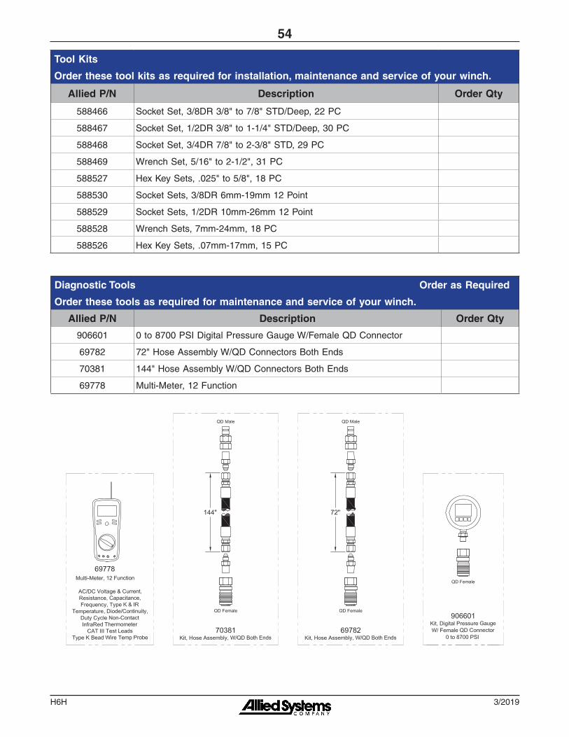
Tool Kits
Order these tool kits as required for installation, maintenance and service of your winch.
Allied P/N Description Order Qty
588466 Socket Set, 3/8DR 3/8" to 7/8" STD/Deep, 22 PC
588467 Socket Set, 1/2DR 3/8" to 1-1/4" STD/Deep, 30 PC
588468 Socket Set, 3/4DR 7/8" to 2-3/8" STD, 29 PC
588469 Wrench Set, 5/16" to 2-1/2", 31 PC
588527 Hex Key Sets, .025" to 5/8", 18 PC
588530 Socket Sets, 3/8DR 6mm-19mm 12 Point
588529 Socket Sets, 1/2DR 10mm-26mm 12 Point
588528 Wrench Sets, 7mm-24mm, 18 PC
588526 Hex Key Sets, .07mm-17mm, 15 PC
Diagnostic Tools Order as Required
Order these tools as required for maintenance and service of your winch.
Allied P/N Description Order Qty
906601 0 to 8700 PSI Digital Pressure Gauge W/Female QD Connector
69782 72" Hose Assembly W/QD Connectors Both Ends
70381 144" Hose Assembly W/QD Connectors Both Ends
69778 Multi-Meter, 12 Function

H6H
55
3/2019
Section 7
Numerical Index
3/2019H6H
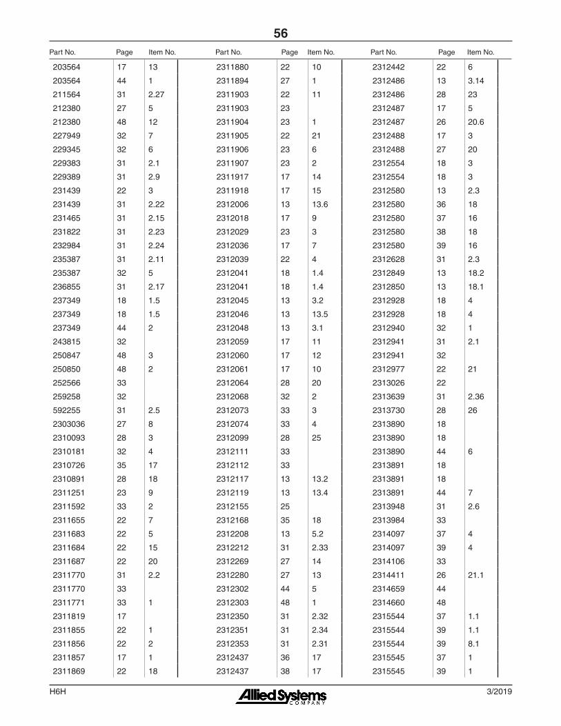
56Part No. Page Item No. Part No. Page Item No. Part No. Page Item No.
203564 17 13
203564 44 1
211564 31 2.27
212380 27 5
212380 48 12
227949 32 7
229345 32 6
229383 31 2.1
229389 31 2.9
231439 22 3
231439 31 2.22
231465 31 2.15
231822 31 2.23
232984 31 2.24
235387 31 2.11
235387 32 5
236855 31 2.17
237349 18 1.5
237349 18 1.5
237349 44 2
243815 32
250847 48 3
250850 48 2
252566 33
259258 32
592255 31 2.5
2303036 27 8
2310093 28 3
2310181 32 4
2310726 35 17
2310891 28 18
2311251 23 9
2311592 33 2
2311655 22 7
2311683 22 5
2311684 22 15
2311687 22 20
2311770 31 2.2
2311770 33
2311771 33 1
2311819 17
2311855 22 1
2311856 22 2
2311857 17 1
2311869 22 18
2311880 22 10
2311894 27 1
2311903 22 11
2311903 23
2311904 23 1
2311905 22 21
2311906 23 6
2311907 23 2
2311917 17 14
2311918 17 15
2312006 13 13.6
2312018 17 9
2312029 23 3
2312036 17 7
2312039 22 4
2312041 18 1.4
2312041 18 1.4
2312045 13 3.2
2312046 13 13.5
2312048 13 3.1
2312059 17 11
2312060 17 12
2312061 17 10
2312064 28 20
2312068 32 2
2312073 33 3
2312074 33 4
2312099 28 25
2312111 33
2312112 33
2312117 13 13.2
2312119 13 13.4
2312155 25
2312168 35 18
2312208 13 5.2
2312212 31 2.33
2312269 27 14
2312280 27 13
2312302 44 5
2312303 48 1
2312350 31 2.32
2312351 31 2.34
2312353 31 2.31
2312437 36 17
2312437 38 17
2312442 22 6
2312486 13 3.14
2312486 28 23
2312487 17 5
2312487 26 20.6
2312488 17 3
2312488 27 20
2312554 18 3
2312554 18 3
2312580 13 2.3
2312580 36 18
2312580 37 16
2312580 38 18
2312580 39 16
2312628 31 2.3
2312849 13 18.2
2312850 13 18.1
2312928 18 4
2312928 18 4
2312940 32 1
2312941 31 2.1
2312941 32
2312977 22 21
2313026 22
2313639 31 2.36
2313730 28 26
2313890 18
2313890 18
2313890 44 6
2313891 18
2313891 18
2313891 44 7
2313948 31 2.6
2313984 33
2314097 37 4
2314097 39 4
2314106 33
2314411 26 21.1
2314659 44
2314660 48
2315544 37 1.1
2315544 39 1.1
2315544 39 8.1
2315545 37 1
2315545 39 1

H6H
57
3/2019
Part No. Page Item No. Part No. Page Item No. Part No. Page Item No.
2315546 37 2
2315546 39 2
2315548 37
2315549 39
2315555 37 7
2315555 39 7
2316071 18
2316071 18 1.1
2316071 18 1.1
2316072 18 2
2316108 31 2.3
2316109 31 2.4
2316162 13 3.6
2316468 18
2316469 18 2
2316491 17 7
133927W 28 10
133927W 48 16
137153W 22 16
137155W 22 17
141671W 28 19
141674W 28 1
149541W 26 20.8
149542W 26 20.9
149543W 26 20.1
151589W 13 3.9
15158W 28 5
151646W 13 3.1
15166W 36 15
15166W 37 13
15166W 38 15
15166W 39 13
15176W 31 2.14
15178W 31 2.26
15272W 13 2.4
15272W 36 16
15272W 37 14
15272W 38 16
15272W 39 14
15290W 13 2.5
15315W 13 2.6
15319W 13 3.13
15862W 27 4
15862W 48 11
15881W 28 8
15881W 48 14
159940W 27 10
159940W 48 8
16001W 35 9
16001W 36 6
16001W 37 5
16001W 38 6
16001W 39 5
16829W 28 16
172808W 28 7
172810W 28 24
173607W 37 15
173607W 39 15
175646W 28 14
175647W 28 13
175648W 28 12
177192W 18 1.8
177192W 18 1.8
18668W 37 12
18668W 38 14
18668W 39 12
18669W 36 14
21420W 13 3.11
221336W 35 12
221577W 28 4
221716W 18 1.3
221716W 18 1.3
221717W 27 16
221767W 18 1.7
221767W 18 1.7
221771W 28 17
221777W 18 1.9
221777W 18 1.9
222713W 23 10
226374W 36 12
226374W 37 10
226374W 38 12
226374W 39 10
230064W 44 4
2300668W 17 16
2300668W 48 4
2300669W 17 17
2300669W 48 5
2300962W 13 3.12
2301706W 35 5
2301706W 35 20
2301706W 36 4
2301706W 37 3
2301706W 38 4
2301706W 39 3
2301718W 36 8
2301718W 38 8
2301721W 36 11
2301721W 37 9
2301721W 38 11
2301721W 39 9
2301722W 36 3
2301722W 38 3
2301724W 37 8.1
2301726W 36 9
2301726W 37 8
2301726W 38 9
2301726W 39 8
2301727W 36 1
2301727W 38 1
2301732W 38
2301748W 35
2301749W 35 1
2301783W 28 15
2301907W 35 2
2301910W 35 7
2301919W 35 14
2301920W 35 13
2301924W 35 19
2301925W 35 15
2301961W 37 1.2
2301961W 37 8.2
2301961W 39 1.2
2301961W 39 8.2
2302120W 35 11
2302311W 27 17
2302311W 48 9
2302624W 27 9
2302625W 27 11
2303221W 13 2.2
2303992W 22 13
230406W 48 13
230407W 22 19
2304803W 27 15
2305096W 27 7
3/2019H6H
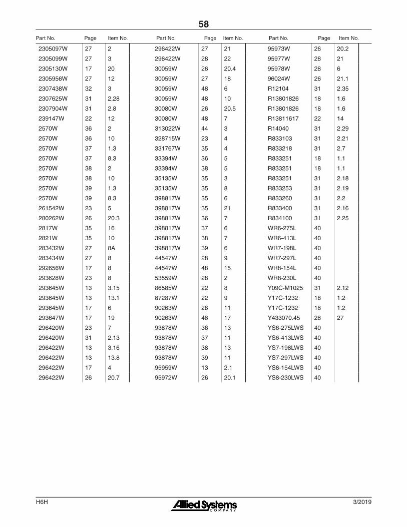
58
2305097W 27 2
2305099W 27 3
2305130W 17 20
2305956W 27 12
2307438W 32 3
2307625W 31 2.28
2307904W 31 2.8
239147W 22 12
2570W 36 2
2570W 36 10
2570W 37 1.3
2570W 37 8.3
2570W 38 2
2570W 38 10
2570W 39 1.3
2570W 39 8.3
261542W 23 5
280262W 26 20.3
2817W 35 16
2821W 35 10
283432W 27 8A
283434W 27 8
292656W 17 8
293628W 23 8
293645W 13 3.15
293645W 13 13.1
293645W 17 6
293647W 17 19
296420W 23 7
296420W 31 2.13
296422W 13 3.16
296422W 13 13.8
296422W 17 4
296422W 26 20.7
296422W 27 21
296422W 28 22
30059W 26 20.4
30059W 27 18
30059W 48 6
30059W 48 10
30080W 26 20.5
30080W 48 7
313022W 44 3
328715W 23 4
331767W 35 4
33394W 36 5
33394W 38 5
35135W 35 3
35135W 35 8
398817W 35 6
398817W 35 21
398817W 36 7
398817W 37 6
398817W 38 7
398817W 39 6
44547W 28 9
44547W 48 15
53559W 28 2
86585W 22 8
87287W 22 9
90263W 28 11
90263W 48 17
93878W 36 13
93878W 37 11
93878W 38 13
93878W 39 11
95959W 13 2.1
95972W 26 20.1
95973W 26 20.2
95977W 28 21
95978W 28 6
96024W 26 21.1
R12104 31 2.35
R13801826 18 1.6
R13801826 18 1.6
R13811617 22 14
R14040 31 2.29
R833103 31 2.21
R833218 31 2.7
R833251 18 1.1
R833251 18 1.1
R833251 31 2.18
R833253 31 2.19
R833260 31 2.2
R833400 31 2.16
R834100 31 2.25
WR6-275L 40
WR6-413L 40
WR7-198L 40
WR7-297L 40
WR8-154L 40
WR8-230L 40
Y09C-M1025 31 2.12
Y17C-1232 18 1.2
Y17C-1232 18 1.2
Y433070.45 28 27
YS6-275LWS 40
YS6-413LWS 40
YS7-198LWS 40
YS7-297LWS 40
YS8-154LWS 40
YS8-230LWS 40
Part No. Page Item No. Part No. Page Item No. Part No. Page Item No.


599039W-SHANTUI 3/2019 Printed in U.S.A.
®To find a dealer in your area,Call: (503) 625-2560,Fax: (503) 625-7269, orEmail: [email protected], orVisit our website: http://www.alliedsystems.com