customer guideline sub-transmission connected embedded ... · customer guideline - sub-transmission...
TRANSCRIPT

CUSTOMER GUIDELINE
Version 3
WARNING: PRINTED COPIES OF THIS DOCUMENT MAY NOT BE THE LATEST. THE MOST UP-TO-DATE VERSION IS LOCATED ON THE POWERCOR WEBSITE.
CUSTOMER GUIDELINE – Sub-Transmission Connected Embedded Generation

CUSTOMER GUIDELINE - Sub-Transmission Connected Embedded Generation CitiPower Pty Powercor Australia LTD
Version 3
WARNING: PRINTED COPIES OF THIS DOCUMENT MAY NOT BE THE LATEST. THE MOST UP-TO-DATE VERSION IS LOCATED ON THE POWERCOR WEBSITE.
Table of Contents
1. Introduction and Purpose ..................................................................................................................... 4
1.1. Introduction ........................................................................................................................................ 4
1.2. Purpose ............................................................................................................................................... 4
1.3. Disclaimer ........................................................................................................................................... 5
2. Definitions ............................................................................................................................................. 6
2.1. Regulatory Terms ................................................................................................................................ 6
2.2. Technical Terms .................................................................................................................................. 7
3. Standards and Guidelines ..................................................................................................................... 9
3.1. Australian Standards ........................................................................................................................... 9
3.2. Other International Standards .......................................................................................................... 10
3.3. Access Standards and NER Conditions .............................................................................................. 10
4. The CitiPower/Powercor Network ...................................................................................................... 11
5. Connection Process ............................................................................................................................ 12
5.1. NER Chapter 5 Connection Process .................................................................................................. 12
5.2. Non Registered Embedded Generators ............................................................................................ 12
6. Technical Requirements ..................................................................................................................... 13
6.1. Quality of Supply ............................................................................................................................... 13
6.2. Reliability of Supply........................................................................................................................... 14
6.3. Operation of Generators and the effect on network and customers............................................... 14
6.4. Minimum Customer Installation Requirements ............................................................................... 14
6.5. Embedded Generator Transformer Requirements ........................................................................... 14
6.6. Primary Plant Requirements ............................................................................................................. 15
6.7. Asset Interface Labelling ................................................................................................................... 16
6.8. Fault level Contribution .................................................................................................................... 16
6.9. CitiPower/Powercor Asset Augmentation ........................................................................................ 17
6.10. Auto Reclose ................................................................................................................................... 18
6.11. Synchronisation .............................................................................................................................. 18
6.12. Islanding .......................................................................................................................................... 19
6.13. Remote Control & Monitoring Requirements ................................................................................ 19
6.13.1. SCADA Control ..................................................................................................................... 20
6.13.2. SCADA Monitoring ............................................................................................................... 20
6.13.3. SCADA Metering .................................................................................................................. 21
6.14. Protection Requirements ................................................................................................................ 22
CUSTOMER GUIDELINE - Sub-Transmission Connected Embedded Generation CitiPower Pty Powercor Australia LTD
Version 3
WARNING: PRINTED COPIES OF THIS DOCUMENT MAY NOT BE THE LATEST. THE MOST UP-TO-DATE VERSION IS LOCATED ON THE POWERCOR WEBSITE.
6.14.1. Customer Substation Protection ......................................................................................... 22
6.14.2. CitiPower/Powercor 66 kV Line Protection ......................................................................... 23
6.14.1. Adjacent CitiPower/Powercor Zone Substations ................................................................ 24
6.14.2. Adjacent Transmission Terminal Stations ........................................................................... 25
6.14.3. Fault Clearance Times.......................................................................................................... 25
6.14.4. Export Limited Connection .................................................................................................. 25
6.15. Communication Requirements ....................................................................................................... 25
6.15.1. General Requirements......................................................................................................... 25
6.15.2. Fibre Optic Cable ................................................................................................................. 26
6.15.3. Radio .................................................................................................................................... 26
6.15.4. 3G/4G Network Access ........................................................................................................ 26
6.15.5. Telephone Line Isolation ..................................................................................................... 27
6.15.1. AEMO Metering Communications ....................................................................................... 27
6.16. Auxiliary Supply Requirements ....................................................................................................... 28
6.16.1. DC Supply Requirements ..................................................................................................... 28
6.16.2. AC Supply Requirements ..................................................................................................... 28
6.16.3. Standby Supply Requirements ............................................................................................ 29
6.17. Interface Requirements .................................................................................................................. 29
6.18. Connection Configuration ............................................................................................................... 29
6.19. CitiPower/Powercor Cubicle Requirements ................................................................................... 31
6.20. Customer Documentation Requirements ....................................................................................... 32
7. Testing and Commissioning ................................................................................................................ 33
8. Embedded Generator Operation and Maintenance .......................................................................... 34
9. Installation Approvals ......................................................................................................................... 35
10. Revenue Metering .......................................................................................................................... 36
10.1. General Requirements .................................................................................................................... 36
10.2. Market Generator Requirements ................................................................................................... 37
10.3. Non-Market Generator Requirements ........................................................................................... 37
11. Environmental ................................................................................................................................ 38
12. Safety .............................................................................................................................................. 39
13. Contact ........................................................................................................................................... 39
APPENDIX A – Typical Secondary Interface Terminal Strips .................................................................... 40

CUSTOMER GUIDELINE - Sub-Transmission Connected Embedded Generation CitiPower Pty Powercor Australia LTD
Page 4 of 43 Version 3
WARNING: PRINTED COPIES OF THIS DOCUMENT MAY NOT BE THE LATEST. THE MOST UP-TO-DATE VERSION IS LOCATED ON THE POWERCOR WEBSITE.
1. Introduction and Purpose
1.1. Introduction These guidelines are intended to cover the installation of generating sources of capacity greater than ten megawatt (10 MW) which existing or new customers wish to connect to the CitiPower/Powercor sub–transmission (nominally 66kV) system that is part of the CitiPower/Powercor distribution system network.
1.2. Purpose The guidelines have been prepared in order to facilitate generator connection. These Guidelines should be read in conjunction with the National Electricity Rules (NER) and any other relevant standards and regulations.
The aim of these Guidelines is to ensure that:
Reliability and quality of the grid supply to other customers is not to be adversely affected by operation of the customer’s generating plant.
The safety of other customers and of CitiPower/Powercor employees and contractors is not put at risk.
The customer’s plant is of an accepted design and capable of operating reliably for extended periods.
The connection complies with the requirements of CitiPower/Powercor.
Prior to the commencement of connection works by CitiPower/Powercor a formal Network Augmentation agreement must be executed. This agreement will contain Schedules which describe all key technical and commercial aspects of the agreement between the two parties.
The installation of a private generating plant must comply with the Electricity Safety Act and its Regulations.
It is also the responsibility of the Customer intending to install a private generating plant to ensure the installation and operation of the plant conforms to the requirements of all other Government and statutory authorities.

CUSTOMER GUIDELINE - Sub-Transmission Connected Embedded Generation CitiPower Pty Powercor Australia LTD
Version 3 Page 5 of 43
WARNING: PRINTED COPIES OF THIS DOCUMENT MAY NOT BE THE LATEST. THE MOST UP-TO-DATE VERSION IS LOCATED ON THE POWERCOR WEBSITE.
1.3. Disclaimer While CitiPower/Powercor makes every effort to ensure that this information and material is current and accurate, the information and material is provided to you on the understanding that:
CitiPower/Powercor makes no warranty, guarantee or promise, express or implied, in relation to the content or accuracy of this information and material.
You will seek verification and/or professional advice from an independent source before relying on or acting upon any of this information and material.
CitiPower/Powercor is not liable or responsible in any way for the results of any actions taken on the basis of this information and material.
To the fullest extent permitted by law, CitiPower/Powercor expressly excludes any and all liability whatsoever and responsibility to any person arising in connection with their use or reliance on the information and material in whole or in part.
Page 6 of 43 Version 3
WARNING: PRINTED COPIES OF THIS DOCUMENT MAY NOT BE THE LATEST. THE MOST UP-TO-DATE VERSION IS LOCATED ON THE POWERCOR WEBSITE.
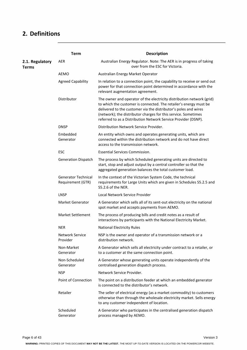
2. Definitions
Term Description
2.1. Regulatory Terms
AER Australian Energy Regulator. Note: The AER is in progress of taking over from the ESC for Victoria.
AEMO Australian Energy Market Operator
Agreed Capability In relation to a connection point, the capability to receive or send out power for that connection point determined in accordance with the relevant augmentation agreement.
Distributor The owner and operator of the electricity distribution network (grid) to which the customer is connected. The retailer’s energy must be delivered to the customer via the distributor’s poles and wires (network); the distributor charges for this service. Sometimes referred to as a Distribution Network Service Provider (DSNP).
DNSP Distribution Network Service Provider.
Embedded Generator
An entity which owns and operates generating units, which are connected within the distribution network and do not have direct access to the transmission network.
ESC Essential Services Commission.
Generation Dispatch The process by which Scheduled generating units are directed to start, stop and adjust output by a central controller so that the aggregated generation balances the total customer load.
Generator Technical Requirement (GTR)
In the context of the Victorian System Code, the technical requirements for Large Units which are given in Schedules S5.2.5 and S5.2.6 of the NER.
LNSP Local Network Service Provider
Market Generator A Generator which sells all of its sent-out electricity on the national spot market and accepts payments from AEMO.
Market Settlement The process of producing bills and credit notes as a result of interactions by participants with the National Electricity Market.
NER National Electricity Rules
Network Service Provider
NSP is the owner and operator of a transmission network or a distribution network.
Non-Market Generator
A Generator which sells all electricity under contract to a retailer, or to a customer at the same connection point.
Non-Scheduled Generator
A Generator whose generating units operate independently of the centralised generation dispatch process.
NSP Network Service Provider.
Point of Connection The point on a distribution feeder at which an embedded generator is connected to the distributor’s network.
Retailer The seller of electrical energy (as a market commodity) to customers otherwise than through the wholesale electricity market. Sells energy to any customer independent of location.
Scheduled Generator
A Generator who participates in the centralised generation dispatch process managed by AEMO.

CUSTOMER GUIDELINE - Sub-Transmission Connected Embedded Generation CitiPower Pty Powercor Australia LTD
Version 3 Page 7 of 43
WARNING: PRINTED COPIES OF THIS DOCUMENT MAY NOT BE THE LATEST. THE MOST UP-TO-DATE VERSION IS LOCATED ON THE POWERCOR WEBSITE.
Term Description
TNSP Transmission Network Service Provider.
Transmission Network
A network within any participating jurisdiction operating at nominal voltages of 220 kV and above plus:
(a) any part of a network operating at nominal voltages between 66 kV and 220kV that operates in parallel to and provides support to the higher voltage transmission network;
(b) any part of a network operating at nominal voltages between 66 kV and 220kV that is not referred to in paragraph (a) but is deemed by the AER to be part of the transmission network.
Table 1 – Glossary of Regulatory Terms
Term Description
2.2. Technical Terms
Active Power The component of an AC electric current which is converted to mechanical power or to heat.
Demand The power consumed by a customer at any point in time; normally measured by integrating kilowatt hours of energy consumed over a period 15 or 30 minutes, and expressed as an average in kilowatts. May sometimes be defined, measured and expressed in kilovolt-amperes.
Distribution Feeder An electric line and associated equipment operating at a voltage of 6.6kV, 11kV or 22kV, which a DNSP uses to distribute electricity.
Distribution Network
A network which is not a transmission network.
Distribution System A distribution network, together with the connection assets associated with the distribution network, which is connected to another transmission or distribution system. Connection assets on their own do not constitute a distribution system.
Fault Level The maximum electrical current, usually expressed in thousands of amperes (kA), which can flow at a point in the supply network if one phase of the supply is short-circuited to earth or to one or more of the other phases.
Power Factor A measure of the relative proportions of active power and reactive power in an AC load current; if p.f. = 1, all current is used in producing heat or mechanical power; if p.f. = 0, then all is used in maintaining magnetic or electric fields.
Quality of Supply (At a point of supply to a customer): The degree to which the voltage of the electricity supply departs from a pure 3-phase sinusoidal waveform of constant magnitude and frequency.
Reliability of Supply (To a customer) The extent to which power supply is available without interruption or curtailment over a long period of time. Usually quantified as availability (no. hours available/total no. hours).
Page 8 of 43 Version 3
WARNING: PRINTED COPIES OF THIS DOCUMENT MAY NOT BE THE LATEST. THE MOST UP-TO-DATE VERSION IS LOCATED ON THE POWERCOR WEBSITE.
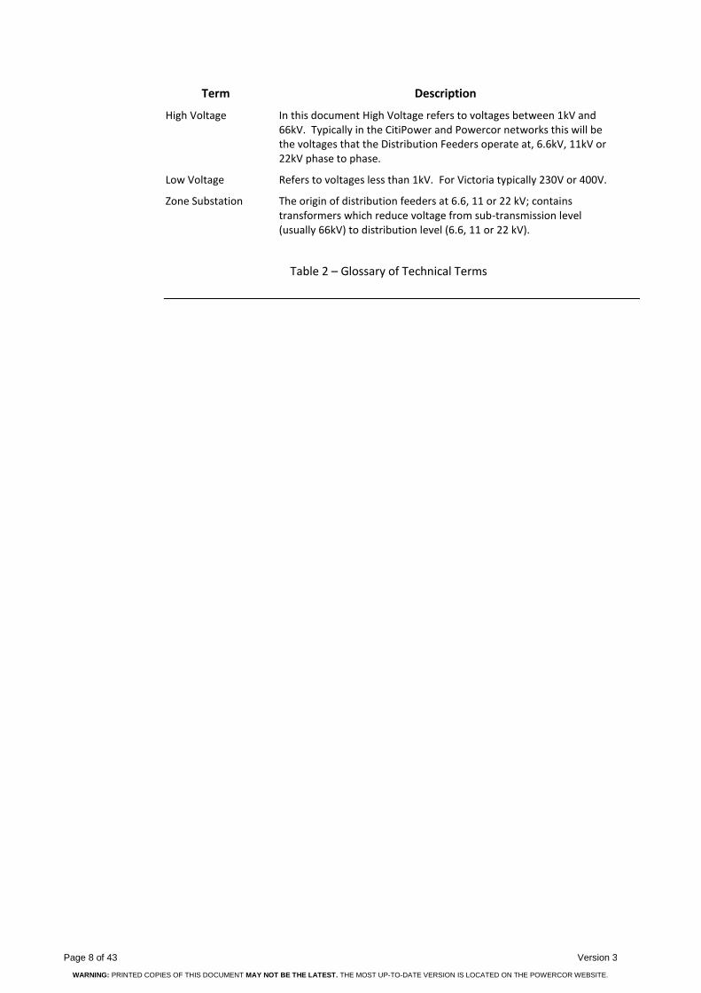
Term Description
High Voltage In this document High Voltage refers to voltages between 1kV and 66kV. Typically in the CitiPower and Powercor networks this will be the voltages that the Distribution Feeders operate at, 6.6kV, 11kV or 22kV phase to phase.
Low Voltage Refers to voltages less than 1kV. For Victoria typically 230V or 400V.
Zone Substation The origin of distribution feeders at 6.6, 11 or 22 kV; contains transformers which reduce voltage from sub-transmission level (usually 66kV) to distribution level (6.6, 11 or 22 kV).
Table 2 – Glossary of Technical Terms

CUSTOMER GUIDELINE - Sub-Transmission Connected Embedded Generation CitiPower Pty Powercor Australia LTD
Version 3 Page 9 of 43
WARNING: PRINTED COPIES OF THIS DOCUMENT MAY NOT BE THE LATEST. THE MOST UP-TO-DATE VERSION IS LOCATED ON THE POWERCOR WEBSITE.
3. Standards and Guidelines
The following lists are not necessarily updated and not exhaustive. They are intended as a guide to prospective Embedded Generators. It is incumbent on the proponent and proponents’ consultant to ensure that the project complies with appropriate standards, guidelines and rules.
3.1. Australian Standards
Australian Standards are employed by the DNSP’s to provide a standard approach for technical requirements. Below is a table that provides a list of relevant Australian Standards.
Australian Standard
Standard Title
AS 1319 Safety signs for occupational environment
AS 1359 General Requirements for Rotating Electrical Machines
AS 1931 High Voltage Test Techniques
AS 2006 Diesel Generators/internal combustion engines
AS 2067 Substations and high voltage installations exceeding 1 kV a.c.
AS 2344 Limits of electromagnetic interference from overhead a.c. powerlines and HV equipment installations in frequency range 0.15 to 1000 MHz
AS 2373 Electric Cables
AS 2374 Power Transformers
AS 2915 Solar Photovoltaic Modules – Performance Requirements
AS/NZS 3000 Electrical Installations (Wiring Rules), 3010 – Electrical Installations – Generating Sets, 3017 – Testing Guidelines
AS/NZS 3008 Electrical installations - Selection of cables - Cables for alternating voltages up to and including 0.6/1 kV
AS 3010 Electrical Installations
AS/NZS 3017 Electrical installations – Testing Guidelines
AS/NZS3100 Approval and test specification – General requirements for electrical equipment
AS 4509 Stand-alone power systems, Parts 1,2,3
AS 4777 Grid Connection of Energy Systems via Inverters, Parts1, 2, 3
AS/NZS 5033 Installation of photovoltaic (PV) arrays
AS 60038 Standard Voltages
AS/NZS 60265.1 High-voltage switches - Switches for rated voltages above 1 kV and less than 52 kV
AN/NZS 61000 Series
Electromagnetic Compatibility
AS 62271 Series High-voltage switchgear and control gear
AS/NZS 7000 Overhead line design standard
Table 3 – Australian Standards

Page 10 of 43 Version 3
WARNING: PRINTED COPIES OF THIS DOCUMENT MAY NOT BE THE LATEST. THE MOST UP-TO-DATE VERSION IS LOCATED ON THE POWERCOR WEBSITE.
3.2. Other International Standards
To assist in providing a standard approach for technical requirements below is a table of International standards and guidelines which may be referred to.
The following list is not necessarily updated and not exhaustive. It is intended as a guide to prospective Embedded Generators. It is incumbent on the proponent and proponents’ consultant to ensure that the project complies with appropriate standards, guidelines and rules.
Standard Document Title
IEEE 519 Recommended Practices and Requirements for Harmonic Control in Electrical Power Systems
G591
Recommendations for the connection of embedded generating plant to the DNO's distribution systems and the provision of standby generators
ETR 1132 Engineering Technical Report No ETR 113
Table 4: Other relevant Standards and Guidelines for reference
3.3. Access Standards and NER Conditions
This document outlines the specific Minimum Access Standards as required by CitiPower/Powercor and should be read in conjunction with the Access Standards as specified in Chapter 5 of the NER with specific reference to Schedules 5.1 and 5.2 (S5.1 and S5.2).
1 Energy Networks Association (UK)
2 Energy Networks Association (UK)
CUSTOMER GUIDELINE - Sub-Transmission Connected Embedded Generation CitiPower Pty Powercor Australia LTD
Version 3 Page 11 of 43
WARNING: PRINTED COPIES OF THIS DOCUMENT MAY NOT BE THE LATEST. THE MOST UP-TO-DATE VERSION IS LOCATED ON THE POWERCOR WEBSITE.
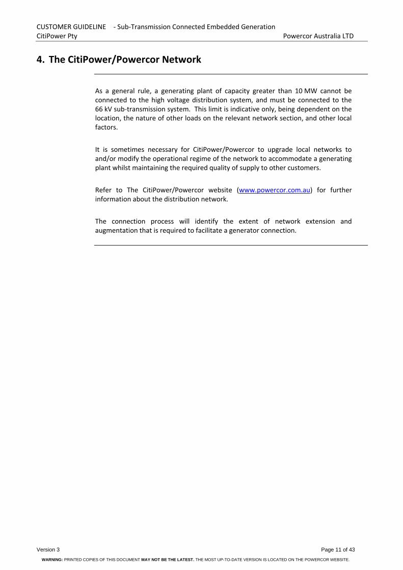
4. The CitiPower/Powercor Network
As a general rule, a generating plant of capacity greater than 10 MW cannot be connected to the high voltage distribution system, and must be connected to the 66 kV sub-transmission system. This limit is indicative only, being dependent on the location, the nature of other loads on the relevant network section, and other local factors.
It is sometimes necessary for CitiPower/Powercor to upgrade local networks to and/or modify the operational regime of the network to accommodate a generating plant whilst maintaining the required quality of supply to other customers.
Refer to The CitiPower/Powercor website (www.powercor.com.au) for further information about the distribution network.
The connection process will identify the extent of network extension and augmentation that is required to facilitate a generator connection.
Page 12 of 43 Version 3
WARNING: PRINTED COPIES OF THIS DOCUMENT MAY NOT BE THE LATEST. THE MOST UP-TO-DATE VERSION IS LOCATED ON THE POWERCOR WEBSITE.
5. Connection Process
Below is a brief summary of the different connection processes and where they are applicable. Further details of the connection process can be found on the ‘Connecting Generation’ section of the Citipower/Powercor website (www.powercor.com.au).
5.1. NER Chapter 5 Connection Process
The NER Chapter 5 connection process is automatically applicable to registered embedded generators with a generation capacity greater than 5 MW. The process, as defined in the amendments to Chapter 5 of the NER effective as of 1 October 2014, includes defined stages of application and details of the required information exchanges between the two parties and the timeframes applicable to each stage.
Customers wishing to connect generators smaller than 5 MW in capacity may also elect to use this process.
See the Citipower/Powercor website (www.powercor.com.au) for further details of the process.
5.2. Non Registered Embedded Generators
Customers wishing to connect an embedded Generator with capacity less than 5 MW and not electing to go through the NER Chapter 5 process are subject to this process.
See the Citipower/Powercor website (www.powercor.com.au) for further details of the process.

CUSTOMER GUIDELINE - Sub-Transmission Connected Embedded Generation CitiPower Pty Powercor Australia LTD
Version 3 Page 13 of 43
WARNING: PRINTED COPIES OF THIS DOCUMENT MAY NOT BE THE LATEST. THE MOST UP-TO-DATE VERSION IS LOCATED ON THE POWERCOR WEBSITE.
6. Technical Requirements
The technical requirements have been written to provide the generator proponent with details that have to be considered and addressed in the determination of any connection. Technical requirements surrounding the connection of generation to a network are essential and must be addressed to ensure the overall integrity of the network, its impact on public health and safety, existing customers, the network assets and any future connection or network configuration.
Unless otherwise stated, the requirements outlined in this section are applicable to ALL embedded generators connecting to the CitiPower/Powercor Sub-transmission Network.
6.1. Quality of Supply
The Victorian Electricity Distribution Code (VEDC) requires electricity DNSPs to maintain the quality of electricity supply to its customers in respect of:
Steady state voltage
Voltage fluctuations
Harmonic voltages
Voltage unbalance
In turn, customers are required by the same code to control the following at their point of connection:
The power factor of their generation and load.
The harmonic currents generated by their generators and loads.
The load balance between phases.
The magnitude and rate of occurrence of generation fluctuations (which cause corresponding voltage fluctuations to be imposed on other customers).
The regulatory limits applicable to each of the above quality indicators may be found in the Victorian Electricity Distribution Code, which can be viewed on the website of the Essential Services Commission at www.esc.vic.gov.au.
The customer shall comply with these codes and CitiPower/Powercor will nominate any additional requirements.

Page 14 of 43 Version 3
WARNING: PRINTED COPIES OF THIS DOCUMENT MAY NOT BE THE LATEST. THE MOST UP-TO-DATE VERSION IS LOCATED ON THE POWERCOR WEBSITE.
6.2. Reliability of Supply
In connecting onto the network the level of reliability should be taken into account. In general the highest level of reliability exists in built-up areas where intermeshed sub-transmission systems exist. In rural areas the level of reliability may be significantly affected by long radial sub-transmission systems. In such areas the network is predominantly of bare overhead conductors subject to many external influences.
6.3. Operation of Generators and the effect on network and customers
For large generation it is expected that the generation will ride through transmission, sub-transmission and distribution faults as specified in the NER.
The stability performance of the generator shall be such as not to impact adversely on existing CitiPower/Powercor customers. CitiPower/Powercor may require stability studies to confirm this.
If required the individual machine model will need to be proven to match the machine specification and designated response.
6.4. Minimum Customer Installation Requirements
Every customer installation which interfaces an embedded generating plant with CitiPower/Powercor’s network shall include as a minimum:
An incoming circuit breaker
associated protection systems
A mechanically interlocked line disconnect switch and earth switch combination on the CitiPower/Powercor network side of the incoming circuit breaker. The earth switch shall be on the line side of the isolating switch and the interlocking shall prevent both switches being closed at the same time.
The customer’s installation must be designed/approved by an experienced electrical power engineer. All work must conform to the appropriate Australian Standards. The customer is responsible for arranging all planning and building permits.
For a 66 kV point of connection, CitiPower/Powercor has additional specific requirements for the Customer’s substation regarding:
Building space provision for CitiPower/Powercor protection and control equipment cubicles and wallboxes
Personnel access to switchyard and control building
Signage, nameplates and labels
6.5. Embedded Generator Transformer Requirements
The generation station transformer/s must be connected to the CitiPower/Powercor distribution network via an unearthed winding to prevent the generating station being a source of earth fault current. (i.e. There must be no zero sequence source.)

CUSTOMER GUIDELINE - Sub-Transmission Connected Embedded Generation CitiPower Pty Powercor Australia LTD
Version 3 Page 15 of 43
WARNING: PRINTED COPIES OF THIS DOCUMENT MAY NOT BE THE LATEST. THE MOST UP-TO-DATE VERSION IS LOCATED ON THE POWERCOR WEBSITE.
6.6. Primary Plant Requirements
The customers incoming 66 kV CB shall be fitted with at least two (2) electrically independent trip coils. Access to both these trip coils is required by CitiPower/Powercor to facilitate independent tripping of this CB from the duplicate 66 kV Line protection. (X & Y).
The customer shall make available to CitiPower/Powercor:
Two off three phase sets of protection class CT’s for CitiPower/Powercor protection application
One off three phase set of metering class CT’s for CitiPower/Powercor metering application
The standard CitiPower/Powercor protection CT ratios and performance required are as follows:
1600/1200/900/5 0.2PX100 R=0.15 ohm on 300/5
These CT cores shall be installed on the customer’s transformer side of the customer’s transformer protection CT’s such that the CitiPower/Powercor and the customer’s protection zones overlap.
The minimum requirement for CitiPower/Powercor metering CT ratios and performance are as follows:
800/600/5 30 VA Class 0.5M on 200/5
Note that the Retailer’s Revenue metering provider will require access to an additional dedicated revenue metering set of CT’s of the appropriate class and a dedicated revenue metering VT winding of the appropriate class. (Refer to Section 10, Revenue Metering, below)
The customer shall also make available to CitiPower/Powercor one off three phase set of 66 kV voltages from protection class VT’s for CitiPower/Powercor protection and metering applications.
CitiPower/Powercor requires the VT ratio to be 66,000/√3 to 110/√3 and performance to be at least 0.5M1P. A Rated Voltage Factor of 1.9 for 30 secs is required.
The VT’s that this supply is derived from must be mounted on the 66 kV line side of the customers incoming CB.
All protection and metering CT and VT connections shall be made available at the designated secondary interface.

Page 16 of 43 Version 3
WARNING: PRINTED COPIES OF THIS DOCUMENT MAY NOT BE THE LATEST. THE MOST UP-TO-DATE VERSION IS LOCATED ON THE POWERCOR WEBSITE.
Details of the customer’s main transformer/s and installation shall be provided to CitiPower/Powercor as soon as known and shall include at least the following details:
Vector group.
Impedance.
Tapping range and tap percentage.
Cable/overhead line impedance between transformer and associated LT transformer CB. (Not required if both transformer and CB are located in the customer substation switchyard.)
If a Neutral Earthing Resistor is connected between the transformer neutral and station earth CitiPower/Powercor require the following information:
Resistance in ohms of the resistor
Short time current rating and related time
6.7. Asset Interface Labelling
Where the generation is connected and synchronised to the network the asset interface must be clearly labelled and defined for ownership and responsibility at the point of supply.
6.8. Fault level Contribution
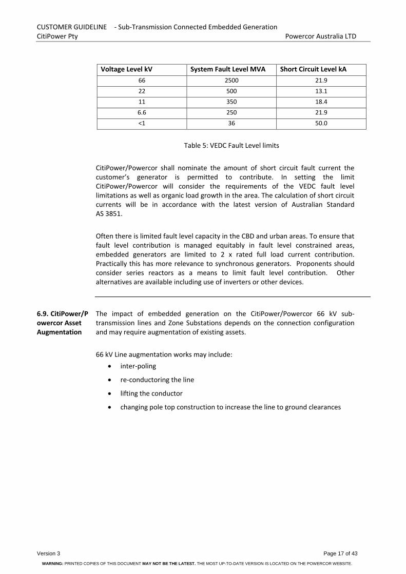
As per the VEDC an embedded generator must design and operate its embedded generating unit so that it does not cause fault levels in the distribution system to exceed the levels specified in Table 5, below.
CUSTOMER GUIDELINE - Sub-Transmission Connected Embedded Generation CitiPower Pty Powercor Australia LTD
Version 3 Page 17 of 43
WARNING: PRINTED COPIES OF THIS DOCUMENT MAY NOT BE THE LATEST. THE MOST UP-TO-DATE VERSION IS LOCATED ON THE POWERCOR WEBSITE.
Voltage Level kV System Fault Level MVA Short Circuit Level kA
66 2500 21.9
22 500 13.1
11 350 18.4
6.6 250 21.9
<1 36 50.0
Table 5: VEDC Fault Level limits
CitiPower/Powercor shall nominate the amount of short circuit fault current the customer’s generator is permitted to contribute. In setting the limit CitiPower/Powercor will consider the requirements of the VEDC fault level limitations as well as organic load growth in the area. The calculation of short circuit currents will be in accordance with the latest version of Australian Standard AS 3851.
Often there is limited fault level capacity in the CBD and urban areas. To ensure that fault level contribution is managed equitably in fault level constrained areas, embedded generators are limited to 2 x rated full load current contribution. Practically this has more relevance to synchronous generators. Proponents should consider series reactors as a means to limit fault level contribution. Other alternatives are available including use of inverters or other devices.
6.9. CitiPower/Powercor Asset Augmentation
The impact of embedded generation on the CitiPower/Powercor 66 kV sub-transmission lines and Zone Substations depends on the connection configuration and may require augmentation of existing assets.
66 kV Line augmentation works may include:
inter-poling
re-conductoring the line
lifting the conductor
changing pole top construction to increase the line to ground clearances

Page 18 of 43 Version 3
WARNING: PRINTED COPIES OF THIS DOCUMENT MAY NOT BE THE LATEST. THE MOST UP-TO-DATE VERSION IS LOCATED ON THE POWERCOR WEBSITE.
Zone Substation augmentation works may include replacement of existing or new:
circuit breakers
bus conductor
switches
isolators
current transformers
Voltage transformers
If the embedded generator 66 kV line is directly connected into a zone substation (see Figure 3, below), zone substation augmentation may include the building of new 66 kV bus work to form a ring bus and the addition of 66 kV circuit breakers in the ring bus.
The customer will incur any augmentation costs caused by the connection of any embedded generator.
6.10. Auto Reclose
The CitiPower/Powercor system standard is for single shot auto reclose on sub-transmission lines. CitiPower/Powercor’s policy is to initiate auto-reclose from the CitiPower/Powercor protection at the switching station or zone substation end only. Any Auto-reclose scheme at the customer’s end of the connecting line will be the responsibility of the customer. A contact will be provided from the CitiPower/Powercor 66 kV Line protection with which the customer may initiate their auto reclose sequence.
Generator manual or automatic restart facilities following a fault and system separation must make allowance for auto reclose operations.
6.11. Synchronisation
All embedded generation synchronism requirements shall be provided within the customer’s generation installation. The customer’s synchronism check can be either automatic or manual, although the CitiPower/Powercor preference is for automatic synchronism check.
An out-of-synchronism reconnection can result in:
Damage to the generator windings, shaft, couplings and prime mover
Damage to other synchronous plant in the region
Mal-operation of protective relays on other utility feeders
Loss of reliability for the general network

CUSTOMER GUIDELINE - Sub-Transmission Connected Embedded Generation CitiPower Pty Powercor Australia LTD
Version 3 Page 19 of 43
WARNING: PRINTED COPIES OF THIS DOCUMENT MAY NOT BE THE LATEST. THE MOST UP-TO-DATE VERSION IS LOCATED ON THE POWERCOR WEBSITE.
It is therefore essential to prove during commissioning that, for all normal conditions of preloading, disconnection of the customer substation from the CitiPower/Powercor network due to a fault results in automatic disconnection of the generator/s in a time which is safely less than the auto reclose delay time.
6.12. Islanding Islanding of an embedded generator occurs when a protection or control operation separates the embedded generator connection from the general body of the network and leaves it to supply the local load.
Any automatic operation elsewhere on the Powercor/CitiPower system that could result in the generating station being islanded to Powercor/CitiPower customers (load) may be required to initiate a remote trip of the customers incoming 66 kV CB via the protection signaling communication scheme to prevent islanding occurring.
The customer’s embedded generation substation protection, generator protection and/or inherent generator design and control system philosophy shall ensure that under all reasonable circumstances, should the customers network separate from the CitiPower/Powercor network, the generator CB’s or the customer incoming CB shall trip ensuring that the embedded generation cannot be islanded to the CitiPower/Powercor load.
The generator must be disconnected from the CitiPower/Powercor network if:
one or more phases of the distribution network at the connection point is lost
a network abnormality causes unacceptable voltage and/or frequency deviations at the network connection point
Anti-islanding protection operate times shall take into consideration the auto reclose dead time such that the generation is disconnected from the CitiPower/Powercor network before a reclose attempt.
The customer’s generator/s may continue to supply the customer’s own load downstream of the network connection point, but must not continue to supply any CitiPower/Powercor customers.
6.13. Remote Control & Monitoring Requirements
The following outlines the local and remote control, plant/equipment status and alarms and metering required by CitiPower/Powercor to operate the system. These requirements are required to enable operational switching to be carried out for both planned and unplanned outage situations and are additional to all other interface requirements specified elsewhere in this document.
Page 20 of 43 Version 3
WARNING: PRINTED COPIES OF THIS DOCUMENT MAY NOT BE THE LATEST. THE MOST UP-TO-DATE VERSION IS LOCATED ON THE POWERCOR WEBSITE.
6.13.1. SCADA Control
The customer shall provide for CitiPower/Powercor remote manual trip control of the customer incomer CB.
CitiPower/Powercor shall provide the control signals in the form of voltage free normally open contacts available at the secondary interface or via DNP3 over Ethernet. If using voltage free contacts the source voltage for wetting the contact will be provided from within the customer site.
The following remote monitoring signals shall be provided to CitiPower/Powercor SCADA in the form of voltage free normally open contacts available at the secondary interface or via DNP3 over Ethernet.
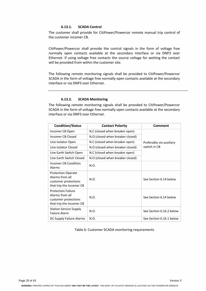
6.13.2. SCADA Monitoring
The following remote monitoring signals shall be provided to CitiPower/Powercor SCADA in the form of voltage free normally open contacts available at the secondary interface or via DNP3 over Ethernet.
Condition/Status Contact Polarity Comment
Incomer CB Open N.C (closed when breaker open)
Preferably via auxiliary switch in CB
Incomer CB Closed N.O (closed when breaker closed)
Line Isolator Open N.C (closed when breaker open)
Line Isolator Closed N.O (closed when breaker closed)
Line Earth Switch Open N.C (closed when breaker open)
Line Earth Switch Closed N.O (closed when breaker closed)
Incomer CB Condition Alarms
N.O.
Protection Operate Alarms from all customer protections that trip the Incomer CB
N.O. See Section 6.14 below
Protection Failure Alarms from all customer protections that trip the Incomer CB
N.O. See Section 6.14 below
Station Service Supply Failure Alarm
N.O. See Section 6.16.2 below
DC Supply Failure Alarms N.O. See Section 6.16.1 below
Table 6: Customer SCADA monitoring requirements
CUSTOMER GUIDELINE - Sub-Transmission Connected Embedded Generation CitiPower Pty Powercor Australia LTD
Version 3 Page 21 of 43
WARNING: PRINTED COPIES OF THIS DOCUMENT MAY NOT BE THE LATEST. THE MOST UP-TO-DATE VERSION IS LOCATED ON THE POWERCOR WEBSITE.
In addition to the above any other relevant alarms or plant status conditions may also be required depending upon the system and generation configuration.
If capacitor banks, statcoms or SVC’s are installed as part of the customers embedded generator substation, then the following additional statuses, as appropriate, are to be provided at the secondary interface for local and remote monitoring:
Capacitor bank in service.
Capacitor bank out of service.
Statcom in service.
Statcom out of service.
SVC in service.
SVC out of service.
The following SCADA monitoring will be provided by CitiPower/Powercor to the Customer in the form of voltage free normally open contacts via Secondary Interface:
Protection Operate Alarms from all protections that trip CitiPower/Powercor zone substation or switching station 66 kV line CB’s that are relevant to the customer
CB closed status from 66 kV line CB’s at the CitiPower/Powercor zone substation or switching station that are relevant to the customer
6.13.3. SCADA Metering
The following SCADA metering quantities at the point of connection and/or at the generator are required by CitiPower/Powercor:
MW (bi-directional)
MV (bi-directional)
66 kV line current (three phase)
66 kV line voltage (three phase)
All CitiPower/Powercor metering quantities shall be derived from a CitiPower/Powercor power quality meter that is connected to the customer metering CT’s and VT’s.

Page 22 of 43 Version 3
WARNING: PRINTED COPIES OF THIS DOCUMENT MAY NOT BE THE LATEST. THE MOST UP-TO-DATE VERSION IS LOCATED ON THE POWERCOR WEBSITE.
6.14. Protection Requirements
6.14.1. Customer Substation Protection
The customer protection design shall be based on detecting all faults within the customer’s distribution system and operating the customers CB’s to isolate the fault without impacting the CitiPower/Powercor system. It is the customer’s responsibility to determine all further performance requirements for the generator protection, given that the functionality will depend on the type of machine and its method of electrical coupling.
The generator protection/control schemes shall allow the generators to ride-through CitiPower/Powercor network faults as prescribed by the NER.
The protection design should include primary protection and back-up protection. Back-up protection can be via duplicated unit protection schemes with local CB failure schemes or via non-unit protection schemes. The back-up protection must also cover all sections of primary plant and must provide protection for both relay failure and CB failure.
A degree of back-up protection may be available from the remote CitiPower/Powercor protection schemes at the zone substation or switching station, but this will depend on system configuration and the type of protection schemes utilised.
CitiPower/Powercor expect that customers duplicate protection schemes (‘X’ and ‘Y’) are supplied from separate ‘X’ & ‘Y’ DC supplies and trip the incoming 66 kV via the CB ‘X’ and ‘Y’ trip coils.
It is recommended to utilise as many unit protection schemes as possible to minimize the number of ‘nested’ over current schemes.
The protection design shall be carried out to ‘best industry practice’ and shall include the following principles:
Adequate CT ratios and performance specifications such that protection mal-operations will not occur under the most severe system fault conditions as a result of CT saturation
Overlapping protection zones with CT’s located such that there are no ‘blind spots’
The Protections systems shall incorporate neutral displacement (ND) protection to detect and isolate all phase-to-ground faults on the immediate CitiPower/Powercor network, which can be back-fed from the customer’s transformer unearthed delta winding.

CUSTOMER GUIDELINE - Sub-Transmission Connected Embedded Generation CitiPower Pty Powercor Australia LTD
Version 3 Page 23 of 43
WARNING: PRINTED COPIES OF THIS DOCUMENT MAY NOT BE THE LATEST. THE MOST UP-TO-DATE VERSION IS LOCATED ON THE POWERCOR WEBSITE.
The customer shall provide Protection Operate alarms to the CitiPower/Powercor SCADA system via the secondary interface (See Section 6.13.2 above and 6.17 below). These alarms may be connected in parallel to give a single common Protection Operate alarm.
The customer shall provide Protection Fail alarms to the CitiPower/Powercor SCADA system via the secondary interface (See Section 6.13.2 above and 6.17 below). These alarms may be connected in parallel to give a single common Protection Fail alarm.
The customer shall submit to CitiPower/Powercor a single line protection diagram of all protection proposed for acceptance at the start of the project. Detailed design and the purchase of any equipment should not proceed until written acceptance is received from CitiPower/Powercor.
See Section 6.20, below, for details of documentation required by CitiPower/Powercor.
6.14.2. CitiPower/Powercor 66 kV Line Protection
For all 66 kV sub-transmission line connections to a customer substation with embedded generation, either from a zone substation or from a switching station, duplicate current differential protection with inbuilt back-up distance protection is the current standard line protection. These schemes incorporate sensitive directional earth fault, bidirectional remote trip facilities, current check based CB failure protection and single shot auto reclose on the CitiPower/Powercor end (See Section 6.10 above).
The current differential schemes operate over the single CitiPower/Powercor fibre optic cable that runs subsidiary to the new 66 kV line. In the event of failure of this single fibre optic cable, the line will still be adequately protected by the inbuilt duplicate back-up distance protection.
Additional bidirectional remote trip facilities shall be provided via independent equipment if required.
In some network connection locations protection signaling paths may be available via the existing CitiPower/Powercor fibre optic network.
Protection Trips from CitiPower/Powercor to Customer via Secondary Interface include but are not limited to:
‘X’ trip of incoming 66 kV CB
‘Y’ trip of incoming 66 kV CB
Back-up trip of customer transformer LT CB/CB’s

Page 24 of 43 Version 3
WARNING: PRINTED COPIES OF THIS DOCUMENT MAY NOT BE THE LATEST. THE MOST UP-TO-DATE VERSION IS LOCATED ON THE POWERCOR WEBSITE.
These trips will be in the form of voltage free normally open contacts available at the secondary interface.
The CitiPower/Powercor line protection equipment will incorporate CB failure protection for the customers incoming CB, which will be initiated by the line protection and will send a back-up trip to customers transformer LT CB/CB’s.
Any trips from the CitiPower/Powercor Protection systems may be required to perform the following actions:
trip of incoming 66 kV CB
trip of customer transformer LT CB/CB’s
trip of any Voltage Support STATCOM
If generation is occurring at the time of the incoming 66 kV CB trip, any trips from the CitiPower/Powercor Protection systems may also be required to initiate one of the following:
an automatic control reduction in generation to zero
a trip of all individual generator CB’s
a trip of other intermediate customer CB’s
6.14.1. Adjacent CitiPower/Powercor Zone Substations
Augmentation of existing protection schemes at CitiPower/Powercor Zone Substations or Voltage Regulator sites may be required depending on the functionality of the existing protection schemes, the network configuration and the proposed network connection arrangement. These augmentations may include:
Replacement, duplication or modification of existing line protection
installation of zone acceleration schemes
Replacement, duplication or modification of existing 66 kV bus protection
addition of CB failure protection schemes
Additionally 66 kV line overload and/or line overvoltage protection may be required.
In some instances additional CT cores, additional line VT’s, control room extensions or, in extreme cases, a new control room may be required.
As a minimum a protection setting review will be required at adjacent stations.

CUSTOMER GUIDELINE - Sub-Transmission Connected Embedded Generation CitiPower Pty Powercor Australia LTD
Version 3 Page 25 of 43
WARNING: PRINTED COPIES OF THIS DOCUMENT MAY NOT BE THE LATEST. THE MOST UP-TO-DATE VERSION IS LOCATED ON THE POWERCOR WEBSITE.
6.14.2. Adjacent Transmission Terminal Stations
Augmentation of existing protection schemes at adjacent terminal Stations may be required depending on the functionality of the existing protection schemes, the network configuration and the proposed network connection arrangement. These augmentations may include:
Replacement, duplication or modification of existing line protection
installation of zone acceleration schemes
6.14.3. Fault Clearance Times
If required, reduced fault clearing times can be achieved on sections of the CitiPower/Powercor sub-transmission system by the application of zone acceleration. Such acceleration schemes require station-to-station communication systems that may not currently exist or may be inadequate. Any upgrade of these communication schemes to provide acceleration would be at the customers cost. (For example: Digital point-to-point radio and associated teleprotection signalling equipment.)
6.14.4. Export Limited Connection
Customer’s connecting subject to an export limit that is less that their installed generation capacity shall install reverse power protection at the point of connection.
6.15. Communication Requirements
6.15.1. General Requirements
There are four (4) different communication paths required into the customer substation:
A protection signalling path between the CitiPower/Powercor zone substation or switching station and the customer substation for current differential protection and protection/control remote signalling.
A SCADA signalling path between the CitiPower/Powercor control room master station and the customer substation for remote control and monitoring via the CitiPower/Powercor RTU.
A power quality metering 3G/4G connection. This may also go via the fibre optic cable to the CitiPower/Powercor zone substation or switching station and then via 3G/4G to the CitiPower/Powercor network metering hub.
A telephone line for voice communications.
The CitiPower/Powercor 66 kV line construction standard for all new lines includes the installation of a single fibre optic cable subsidiary to the line. Generally the protection signalling and SCADA signalling will be via this fibre optic cable. The SCADA signalling will then be via point-to-point radio or other communication channels to the master station.

Page 26 of 43 Version 3
WARNING: PRINTED COPIES OF THIS DOCUMENT MAY NOT BE THE LATEST. THE MOST UP-TO-DATE VERSION IS LOCATED ON THE POWERCOR WEBSITE.
For some network connection locations protection signalling paths, SCADA signalling paths or power quality metering signalling paths may be available via existing CitiPower/Powercor communication networks.
The failure of the protection signalling system may necessitate different actions depending on the actual network connection configuration.
Possible actions that may be required are:
a trip of the incoming 66 kV CB,
a reduction in the level of generation,
a blocking of the 66 kV line auto reclose function,
a block of the closing of customer’s CB’s that are used for generator synchronisation.
Citipower/Powercor Communications Services will provide real time monitoring to AEMO of the site in accordance with the NER.
6.15.2. Fibre Optic Cable
For the CitiPower/Powercor fibre optic cable the customer is required to run a suitable conduit from the customer substation boundary fence to a nominated location on the control room where CitiPower/Powercor will install a small wall mounted fibre optic termination box.
6.15.3. Radio
Depending on local geographic or signal strength conditions the point-to-point radio for SCADA communications or the Next G modem for power quality metering may have to be installed at the customer’s substation rather than at the CitiPower/Powercor zone substation or switching station. This may require the installation of a pole or other mast assembly to support the radio antenna.
6.15.4. 3G/4G Network Access
CitiPower/Powercor will be accessing the 3G/4G Network for downloading the CitiPower/Powercor Power Quality Meter. This will require the installation of a small antenna on the outside of the control room and the running of a communications cable between the CitiPower/Powercor cubicles and this antenna. This work will be carried out by CitiPower/Powercor in consultation with the customer.

CUSTOMER GUIDELINE - Sub-Transmission Connected Embedded Generation CitiPower Pty Powercor Australia LTD
Version 3 Page 27 of 43
WARNING: PRINTED COPIES OF THIS DOCUMENT MAY NOT BE THE LATEST. THE MOST UP-TO-DATE VERSION IS LOCATED ON THE POWERCOR WEBSITE.
6.15.5. Telephone Line Isolation
If copper based telecommunications circuits are required at the customer substation, the customer shall provide the required high voltage isolation for copper based telecommunications circuits entering the substation. It is the customer’s responsibility to install an appropriate Telecom Entry Point (TEP) box, Telecom Services Interface Unit (TSIU) and a HV communications cable between the two. The TSIU will need to be appropriately equipped with the necessary isolation devices for the services entering the substation.
It should be noted that isolation equipment in the TSIU for Public Switched Telephone Network (PSTN) dial up lines requires either a 24V or 48V DC supply.
CitiPower/Powercor do not require any Telstra Communications service at the customer substation except access to a standard landline telephone if available for operational and maintenance testing voice communications.
6.15.1. AEMO Metering Communications
AEMO have requirements for up to three (3) different types of metering data associated with embedded generators. The need and level of information depends on the Access Standard applicable, level of generation and is negotiated between the generator proponent and AEMO.
The types of data that are/may be required are;
1. Revenue Metering (Energy) Data including MW, MVar, Volts, Amps.
2. Real Time SCADA operational system data.
3. Additional weather and system data. – Ambient Temperature, Wind Speed, Wind Direction.
Under the National Electricity Rules CitiPower/Powercor are responsible for providing the communication system to provide AEMO with this data. CitiPower/Powercor have a strong preference for these three types of data to be supplied via a fibre optic communication link from the generator proponent to the CitiPower/Powercor communications infrastructure for networking back to the AEMO connection point for monitoring the data.
It is also preferred that the data from the generator proponent is in DNP3.0 Protocol format.
The actual method of providing the communication path may vary depending on a number of factors and will be negotiated between CitiPower/Powercor and AEMO.

Page 28 of 43 Version 3
WARNING: PRINTED COPIES OF THIS DOCUMENT MAY NOT BE THE LATEST. THE MOST UP-TO-DATE VERSION IS LOCATED ON THE POWERCOR WEBSITE.
6.16. Auxiliary Supply Requirements
6.16.1. DC Supply Requirements
The CitiPower/Powercor preferred option for DC supplies is that the customer install the station battery/batteries, charger/s and DC panel and make protected, DC supplies available to CitiPower/Powercor. The DC Supplies shall be duplicated to provide separate supplies for X and Y protection.
The CitiPower/Powercor standard protection relay auxiliary DC voltage is 125V and CitiPower/Powercor have a strong preference for the customer’s station battery to be 125V DC. (Otherwise additional non-standard equipment may need to be purchased and held as system spares at the customer cost.)
The customer’s DC supply system shall be monitored and an alarmed for ‘Battery Under-voltage’ and ‘Battery Charger Fail’ to CitiPower/Powercor. These alarm signals will be in the form of voltage free normally open contacts available at the secondary interface.
Typically the characteristics of the DC supplies required by CitiPower/Powercor are:
Nominal Voltage: 125V DC
Maximum variation: + 10%
Maximum load required: 5A DC continuous
Standby capacity: 10 hours at max load (For loss of AC supply to
charger)
Maximum ripple: <1% of the battery charger DC output voltage
6.16.2. AC Supply Requirements
A single phase 240V AC, 50 Hz 10A supply from the customer’s station service panel is required. This supply shall be protected by an MCB with residual current detection.
The AC station service supply status shall be monitored and alarmed for Station Service Supply Fail to CitiPower/Powercor. This status signal will be in the form of voltage free normally open contact available at the secondary interface.
All AC station services supplies shall conform to AS 3000.

CUSTOMER GUIDELINE - Sub-Transmission Connected Embedded Generation CitiPower Pty Powercor Australia LTD
Version 3 Page 29 of 43
WARNING: PRINTED COPIES OF THIS DOCUMENT MAY NOT BE THE LATEST. THE MOST UP-TO-DATE VERSION IS LOCATED ON THE POWERCOR WEBSITE.
6.16.3. Standby Supply Requirements
If an embedded generating plant is associated with an industrial or commercial premise, it is likely that provision must be made for an external source of power to meet essential loads when generator(s) are out of service for maintenance. If the customer requires a standby power supply CitiPower/Powercor will provide an estimate of the costs of the alternate supply and the conditions relating to it.
6.17. Interface Requirements
The physical interfaces between the customer’s plant and CitiPower/Powercor’s assets must be clearly defined in regards to ownership and responsibility and appropriately labelled in a clear and unambiguous manner.
The secondary interface will generally be a row or rows of terminals within a CitiPower/Powercor cubicle, rack frame or wall box. Some signalling and control signals may be communicated via a DNP3 over Ethernet link.
Exact details of the secondary interface will depend on the CitiPower/Powercor network and customer embedded generation connection arrangements and will be detailed in a “CitiPower/Powercor Interface Requirements” document that will be prepared after details of the customers system and protection design proposals have been received and accepted by CitiPower/Powercor.
The customer shall be responsible for the supply and installation of all I/O cabling, wiring and other communication circuits on the customer side of the interface cubicle.
APPENDIX A below, shows a generic secondary systems interface diagram for a HV Generation customer.
6.18. Connection Configuration
The following are examples of acceptable minimum connection configurations.

Page 30 of 43 Version 3
WARNING: PRINTED COPIES OF THIS DOCUMENT MAY NOT BE THE LATEST. THE MOST UP-TO-DATE VERSION IS LOCATED ON THE POWERCOR WEBSITE.
Figure 1 - Minimum requirement for “tee off” connection on 66kV line
Figure 2 - Minimum requirement for connection in 66kV loop arrangement
Terminal station or zone substation 66kV bus
Note: If Statcom/SVC required at the switching station for connection of generator, an additional 66kV circuit breaker will be required in the switching station 66kV ring bus.
Point of Connection
Switching Station
Existing assets
Zone Sub 66kV bus
New assets required for connection of embedded generation
G
Generator
G
Terminal station or zone substation 66kV bus
Zone Sub 66kV bus
Point of Connection
Switching Station
Existing assets
New assets required for connection of embedded generation
Note: If Statcom/SVC required at the switching station for connection of generator, an additional 66kV circuit breaker will be required in the switching
station 66kV ring bus.
Generator

CUSTOMER GUIDELINE - Sub-Transmission Connected Embedded Generation CitiPower Pty Powercor Australia LTD
Version 3 Page 31 of 43
WARNING: PRINTED COPIES OF THIS DOCUMENT MAY NOT BE THE LATEST. THE MOST UP-TO-DATE VERSION IS LOCATED ON THE POWERCOR WEBSITE.
Figure 3 - Minimum requirement for direct connection into Zone Substation
6.19. CitiPower/Powercor Cubicle Requirements
As a minimum, the customer shall allocate space in their control room or switch room for 2 off 19” Cubicles suitable to house CitiPower/Powercor Protection equipment, Control & monitoring equipment and communication equipment. The current CitiPower/Powercor standard is a cubicle of dimensions 2300H X 850W X 650D.
The exact space requirements will be negotiated and confirmed in the Interface document.
G Generator
Terminal Station 66kV bus
Zone Sub 66kV bus
Zone Sub
22kV bus
Point of Supply
Existing assets
New assets required for connection of embedded generation
Note: Statcom/SVC maybe required at the zone substation 66kV ring bus for
connection of generator.
Point of Connection

Page 32 of 43 Version 3
WARNING: PRINTED COPIES OF THIS DOCUMENT MAY NOT BE THE LATEST. THE MOST UP-TO-DATE VERSION IS LOCATED ON THE POWERCOR WEBSITE.
6.20. Customer Documentation Requirements
As well as the information set out in Schedule 5.4 of the NER the customer shall provide CitiPower/Powercor with the following documentation for approval:
A plant electrical single Line diagram of the customer network showing:
o Supply connection points
o All relevant switchboards and switchgear and generator
o All Circuit breaker/s clearly named
o Synchronizing point/s
o All protection and control schemes
o Generator transformer details
Any other schematic diagrams of protection and control schemes
Details of primary and secondary interfaces to the CitiPower/Powercor network
The settings of the customer’s non-unit protection schemes must be coordinated with the CitiPower/Powercor network protection schemes. The Customer shall provide full details of the protection proposals including the following:
Protective relay types and configurations
Protective relay operating characteristics
Proposed relay settings for non-unit protection
Where coordination with existing CitiPower/Powercor settings is not possible, the customer may propose revised protection settings for CitiPower/Powercor equipment. It may then be necessary for CitiPower/Powercor to revise or upgrade their equipment. It should be noted that the CitiPower/Powercor settings can only be revised within the boundaries of good protection design to ensure HV feeder faults are cleared within an appropriate time. The approved protection design or settings must not be changed without prior approval from CitiPower/Powercor.

CUSTOMER GUIDELINE - Sub-Transmission Connected Embedded Generation CitiPower Pty Powercor Australia LTD
Version 3 Page 33 of 43
WARNING: PRINTED COPIES OF THIS DOCUMENT MAY NOT BE THE LATEST. THE MOST UP-TO-DATE VERSION IS LOCATED ON THE POWERCOR WEBSITE.
7. Testing and Commissioning
A detailed Schedule of pre-commissioning tests will be developed for each embedded generator.
The tests required may vary depending on the size and type of generator and the location, and may include the following:
Synchronising checks
Proving correct operation of all protection that may include, but not limited to, loss of mains and neutral overload protection, over-voltage, frequency, reverse power and stator earth fault protection
Proving functionality of communication systems
Harmonic testing
The customer will be required to ensure an electrically trained high voltage operator is present at all times during testing and commissioning to receive and execute DNSP operator instructions.
CitiPower/Powercor will not connect an embedded generator which in the opinion of CitiPower/Powercor is unsatisfactory for connection to the supply system.

Page 34 of 43 Version 3
WARNING: PRINTED COPIES OF THIS DOCUMENT MAY NOT BE THE LATEST. THE MOST UP-TO-DATE VERSION IS LOCATED ON THE POWERCOR WEBSITE.
8. Embedded Generator Operation and Maintenance
Every embedded generator is connected to a part of the network on which maintenance work must be carried out by CitiPower/Powercor or its contractors. Under such conditions CitiPower/Powercor must ensure that the affected section of the network is isolated not only on the zone substation side but also on the generator side. CitiPower/Powercor will in general require the line disconnect switch and earth switch at the customer’s point of supply to be lockable to ensure the safety of maintenance personnel. The line disconnect switch shall be under joint operational control of CitiPower/Powercor and the customer. The line earth switch shall be under the sole operational control of CitiPower/Powercor.
Written operating procedures for the generating plant and associated connection assets must be submitted for CitiPower/Powercor’s agreement prior to commissioning of the plant, and a formal copy held by each party which has been signed by both parties. These operating procedures must not be modified without consultation and agreement with CitiPower/Powercor.
The presence of an embedded generator may also impact on other lines and feeders due to load transfer arrangements on the network. CitiPower/Powercor operations and maintenance personnel may need to contact operators of embedded generators at short notice prior to carrying out any urgent maintenance work on the associated network.
Safety considerations will, on occasion, require a visit to premises by CitiPower/Powercor operations personnel to check the status of the customer’s generator installation. On these occasions the generating plant operators must be available on site at short notice.
The customer’s generating plant and its auxiliaries should be regularly inspected and maintained by suitably qualified and trained personnel in accordance with the instructions of the relevant equipment manufacturers. In particular, work on a gas-fuelled plant must be carried out only by specialist maintenance engineers.
CitiPower/Powercor reserve the right to view any maintenance records at any time and records must be up to date as agreed between the parties involved.
CUSTOMER GUIDELINE - Sub-Transmission Connected Embedded Generation CitiPower Pty Powercor Australia LTD
Version 3 Page 35 of 43
WARNING: PRINTED COPIES OF THIS DOCUMENT MAY NOT BE THE LATEST. THE MOST UP-TO-DATE VERSION IS LOCATED ON THE POWERCOR WEBSITE.
9. Installation Approvals
Prior to the connection of embedded generating plant, the customer shall allow access to the site for CitiPower/Powercor’s representative to inspect the electrical switchgear and protection & control equipment. The customer shall also facilitate the presence of CitiPower/Powercor representatives when the plant safety features are being proven.
CitiPower/Powercor may wish to carry out its own tests prior to commissioning of the plant on the CitiPower/Powercor network. The customer shall allow access to equipment as required. In doing such testing, CitiPower/Powercor assumes no liability in respect of the safety of the customer’s plant.
Subsequent to commissioning of the plant, CitiPower/Powercor must be consulted prior to any modification of the plant, equipment, protection or control schemes.

Page 36 of 43 Version 3
WARNING: PRINTED COPIES OF THIS DOCUMENT MAY NOT BE THE LATEST. THE MOST UP-TO-DATE VERSION IS LOCATED ON THE POWERCOR WEBSITE.
10. Revenue Metering
10.1. General Requirements
Revenue or NEM metering is required for connection of all embedded generation or grid connected alternative sources of supply, and is separate to, and in addition to any SCADA and monitoring equipment required by the customer and/or the Network as defined in this document.
Revenue metering is required to comply with the requirements of the National Electricity Market and specifically with:
The National Electricity Rules chapter 7
(and in particular Section 7.3.1 (i) Requirements for metering installations for non-market generating units)
The Victorian Electricity Customer Metering Code
The National Measurements Act and associated regulations
The Victorian Service and Installation Rules (and in particular chapters 6, 8 and 9)
HV Revenue Metering can only be installed and maintained by AEMO accredited Meter Providers. HV Revenue Metering shall consist of a bi-directional interval meter with 30 minute import and export real energy data streams as required under the NER chapter 7.
However, in accordance with the NER requirements under section 7.3.1(i), CitiPower/Powercor, as the Local Network Service Provider, specifically requires 4 quadrant real and reactive energy interval metering on all 3 phase HV connected metered sites, as part of its approval for connection of an Embedded Generator to its Network. For all HV connected metering sites, regardless of consumption, tariff or actual demand, that metering shall be 15 minute interval data metering.
HV metering VTs and CTs shall be supplied and maintained by the customer. Metering equipment shall comply with regulatory accuracy and standards and be certified with NATA endorsed test results.
While revenue metering is normally provided by the Responsible Person and their selected Meter Provider, the customer or generation operator must ensure the metering installation design and engagement of appropriate RP/MP will comply with these specific requirements, and ensure Revenue metering is segregated from any remote control, monitoring and measuring equipment.
Where the electrical installation incorporates parallel generation facilities in addition to customer load, the metering installation shall be designed as net metering at the point of supply, unless specifically agreed or approved to be designed as gross metering by CitiPower / Powercor as the LNSP.

CUSTOMER GUIDELINE - Sub-Transmission Connected Embedded Generation CitiPower Pty Powercor Australia LTD
Version 3 Page 37 of 43
WARNING: PRINTED COPIES OF THIS DOCUMENT MAY NOT BE THE LATEST. THE MOST UP-TO-DATE VERSION IS LOCATED ON THE POWERCOR WEBSITE.
Where a multiple occupancy has a landlord operated parallel generation or embedded generation facility, it shall be net metered with the landlord’s common area and building services loads, and separate to tenancy metering.
Where a landlord establishes an Embedded Network, any subtractive calculations for export and import at the parent meter will be the responsibility of the Embedded Network Operator and the RP/MP engaged at the Parent Metering.
Where a Generator is the primary purpose of the customer installation, it will be connected as net metering inclusive of its internal own station service, where the generator requires separate LV supply connection for standby/emergency power that may be separately metered at LV.
HV Revenue Metering energy values associated with the settlements in the NEM, or Electricity Retailer transactions, in multiple occupancies and Embedded Networks, may vary significantly from the actual connection point energy and demand loadings applied to the CitiPower and Powercor Distribution Network, and hence Control, Monitoring and Measurement equipment, to be independent to, and segregated from, the Revenue Metering equipment.
10.2. Market Generator Requirements
For Market Generators, the NER assigns primary responsibility for the provision, installation and maintenance of a metering installation to the local Network Service Provider (CitiPower/Powercor) unless otherwise elected by the Market Generator.
CitiPower/Powercor will make an offer for the provision of these services on request and, on acceptance, will provide AEMO with details of the metering installation.
If CitiPower/Powercor’s offer is not accepted, the Market Generator assumes responsibility, and must engage a Metering Provider who is registered with the AEMC. The Market Generator must provide AEMO with details of the metering information.
10.3. Non-Market Generator Requirements
For Non-market Generators, i.e. those selling electricity to a retailer, the requirements are detailed in the Victorian Electricity Metering Code, which is available on the ESC website at www.esc.vic.gov.au.

Page 38 of 43 Version 3
WARNING: PRINTED COPIES OF THIS DOCUMENT MAY NOT BE THE LATEST. THE MOST UP-TO-DATE VERSION IS LOCATED ON THE POWERCOR WEBSITE.
11. Environmental
There may be environmental issues that are outside the scope of the embedded generator itself that proponents should consider.
Each embedded generator technology will present unique environmental issues that the proponent will need to manage. In addition to these there will be environmental issues associated with the electrical connection itself.
These may include:
Easements
Clearances
Visual amenity
Electromagnetic compatibility
Cultural Heritage
Conservation of Native Vegetation
Third Party Land User Consent
Other
The DNSP will likely address many of these issues for the line to the proponent’s boundary but there will be a number of environmental issues that will need to be managed and accountability established.
The proponent should also be aware that if there are significant environmental issues with the power connection that could have been addressed or avoided at the site selection stage, there could be significant cost and delays associated with the connection.

CUSTOMER GUIDELINE - Sub-Transmission Connected Embedded Generation CitiPower Pty Powercor Australia LTD
Version 3 Page 39 of 43
WARNING: PRINTED COPIES OF THIS DOCUMENT MAY NOT BE THE LATEST. THE MOST UP-TO-DATE VERSION IS LOCATED ON THE POWERCOR WEBSITE.
12. Safety
Embedded generators should ensure that safety legislation and standards are complied with including any additional conditions that may be applied by the DNSP. These should include consideration of the connection assets and site security.
Where an embedded generator operator is required to undertake works in the vicinity of DNSP assets, the embedded generator is required to use appropriate practices as per the requirements of ‘the green book’ code of practice and in consultation with the DNSP.
13. Contact
Refer to the ‘Connecting generation’ section of the Citipower/Powercor website (www.powercor.com.au) for contact details.

Page 40 of 43 Version 3
WARNING: PRINTED COPIES OF THIS DOCUMENT MAY NOT BE THE LATEST. THE MOST UP-TO-DATE VERSION IS LOCATED ON THE POWERCOR WEBSITE.
APPENDIX A – Typical Secondary Interface Terminal Strips

CUSTOMER GUIDELINE - Sub-Transmission Connected Embedded Generation CitiPower Pty Powercor Australia LTD
Version 3 Page 41 of 43
WARNING: PRINTED COPIES OF THIS DOCUMENT MAY NOT BE THE LATEST. THE MOST UP-TO-DATE VERSION IS LOCATED ON THE POWERCOR WEBSITE.
CUSTOMER CitiPower/PowercorX1
STATION SERVICE SUPPLY
X 125V DC SUPPLIES
X 125V DC SUPPLY
Y 125V DC SUPPLY
66 kV LINE MVT 110V SECONDARY
66 kV CB X PROT CT
66 kV CB Y PROT CT
66 kV CB METERING CT
X 125V DC SUPPLIES
66 kV X LINE PROT VT SUPPLY
66 kV Y LINE PROT VT SUPPLY
66 kV LINE X CURRENT DIFF CT SUPPLY
66 kV LINE Y CURRENT DIFF CT SUPPLY
POWER QUALITY METERING
DO
UB
LE GP
O
R
R
W
W
B
B
N
N0
Rb 0
Wb0
Bb
1N
b
0R
b 0W
b0B
b
1N
b
0B
b 1N
b
0R
b 0W
b
RW
BN
RW
BN
RW
BN
RW
BN
PO
SN
EGP
OS
NEG
AN
E
A
N
E

Page 42 of 43 Version 3
WARNING: PRINTED COPIES OF THIS DOCUMENT MAY NOT BE THE LATEST. THE MOST UP-TO-DATE VERSION IS LOCATED ON THE POWERCOR WEBSITE.
CUSTOMERCitiPower/Powercor
X2
66 kV LINE DISCONNECT SW
STATUS66 kV LINE DISCONNECTOR & EARTH SW STATUSES
66 kV LINE EARTH SW
STATUS
66 kV LINE CB STATUS &
ALARMS
CUSTOMER PROT OPERATE
INDICATION (FROM ANY PROT THAT TRIPS 66 kV CB)
CUSTOMER PROT FAILURE ALARM
(FROM ANY PROT THAT TRIPS 66 kV
CB)
X 125V DC BATT UV ALARM
X 125V DC BATT CHGER FAIL
ALARM
STATION SERVICE SUPPLY FAIL
ALARM
STATCOM STATUS
STATCOM IN SERVICE
STATCOM O.O.S.
HALF GENERATION TRIPPED
SUCCESSFULLY
REDUCE VOLTS RECEIVED
REDUCE GENERATION RECEIVED
CONTROLLED GENERATION
REDUCTION RECEIVED
66 kV CB MONITORING
66 kV CB TRIP CCT SUPERVISION
LOCAL ALARM UNIT
CitiPower/Powercor RTU
REMOTE SIGNAL ACKNOWLEDGE
Y 125V DC BATT UV ALARM
Y 125V DC BATT CHGER FAIL
ALARM
TYPICAL GENERATION
RUNBACK SIGNAL ACKNOWLEDGE

CUSTOMER GUIDELINE - Sub-Transmission Connected Embedded Generation CitiPower Pty Powercor Australia LTD
Version 3 Page 43 of 43
WARNING: PRINTED COPIES OF THIS DOCUMENT MAY NOT BE THE LATEST. THE MOST UP-TO-DATE VERSION IS LOCATED ON THE POWERCOR WEBSITE.
CUSTOMER CitiPower/Powercor
REDUCE VOLTS
TRIP HALF CONNECTED GENERATION
TOTAL FIRE BAN REDUCE GENERATION
ALARM SIGNALS TO SCADA
X TRIP TO 66 kV LINE CB
CUSTOMER AUTO RECLOSE 66 kV LINE CB
X TRIP TO TRANSFORMER LV CB
X CBF TRIP FROM CUSTOMER X PROT
Y CBF TRIP FROM CUSTOMER Y PROT
ALARM SIGNALS TO CUSTOMER SCADA
OVERVOLTAGE PROT STG 1 START
TRIP HALF OF CONNECTED GENERATION
TOTAL FIREBAN REDUCE GENERATION
CB TRIP AT CP/PC SWITCHING STATION
CB (1) CLOSED STATUS FROM CP/PC SWITCHING STATION
CB (2)CLOSED STATUS FROM CP/PC SWITCHING STATION
NORMAL GENERATION EXCEEDED STG 1 TRIP HALF CONNECTED GENERATION
66 kV LINE X CURRENT DIFF TRIP
NORMAL GENERATION EXCEEDED STG 2 OR TOTAL FIRE BAN LIMIT EXCEEDED TRIP
LINE OVERLOAD STG 2 & 3 TRIP
CP/PC SCADA MANUAL TRIP
Y TRIP TO 66 kV LINE CB
66 kV LINE Y CURRENT DIFF TRIP
AUTO RECLOSE START
66 kV LINE CB CP/PC CBF PROT TRIP
66 kV LINE X CURRENT DIFF REMOTE TRIP TO CP/PC SWITCHING STATION
66 kV LINE Y CURRENT DIFF REMOTE TRIP TO CP/PC SWITCHING STATION
NORMAL GENERATION EXCEEDED STG 1 TRIP ALARM
NORMAL GENERATION EXCEEDED STG 2 TRIP ALARM
TOTAL FIRE BAN LIMIT EXCEEDED TRIP ALARM
X3
TYPICAL GENERATION CONTROL AND RUNBACK SIGNALS