customer instructions ni-3012 network interface device
TRANSCRIPT
203-297, Issue 2
STANDARD RECOMMENDED PROCEDURE 203-297 | ISSUE 2 | MAy 2015 | PAGE 1 OF 4
NI-3012 Network Interface Device — Customer Instructions
Important Instructions
When using your telephone equipment, basic precautions should always be followed to reduce the risk of fire, electric shock, and personal injury, including the following:• Read and understand all instructions before
proceeding.• Follow all warnings and procedures on this instruction
sheet or on the product.• NEVER install telephone wiring during a lightning
storm.• NEVER install telephone jacks in a wet location
unless the jack is specifically designed for use in wet locations.
• NEVER touch uninsulated telephone wires or terminals unless the telephone line has been disconnected at the network interface.
• Use caution when installing or modifying telephone lines.
Save These Instructions
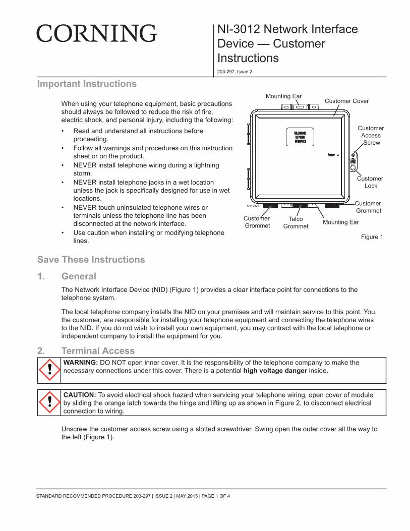
1. GeneralThe Network Interface Device (NID) (Figure 1) provides a clear interface point for connections to the telephone system.
The local telephone company installs the NID on your premises and will maintain service to this point. you, the customer, are responsible for installing your telephone equipment and connecting the telephone wires to the NID. If you do not wish to install your own equipment, you may contract with the local telephone or independent company to install the equipment for you.
2. Terminal AccessWARNING: DO NOT open inner cover. It is the responsibility of the telephone company to make the necessary connections under this cover. There is a potential high voltage danger inside.
CAUTION: To avoid electrical shock hazard when servicing your telephone wiring, open cover of module by sliding the orange latch towards the hinge and lifting up as shown in Figure 2, to disconnect electrical connection to wiring.
Unscrew the customer access screw using a slotted screwdriver. Swing open the outer cover all the way to the left (Figure 1).
Customer Cover
Customer Access Screw
Customer Lock
Customer Grommet
Mounting Ear
Mounting EarCustomer Grommet
TelcoGrommet
KPA-2325
Figure 1

STANDARD RECOMMENDED PROCEDURE 203-297 | ISSUE 2 | MAy 2015 | PAGE 2 OF 4
Figure 2
Figure 3
3. Customer WiringStep 1: Locate terminal to be wired and open cover by sliding orange latch towards the hinge and
lifting up. as shown in Figure 2.Step 2: Use a sharp object to puncture a small hole through one of the grommets located in the
bottom left and right of the housing as shown in Figure 3.Step 3: Pull wire through the hole in the grommet and extend 3 inches past top of box. Route wire to
terminal to be wired. It is not necessary to strip the wires.
Step 4: Feed the wires through the hinge of the module door to the first line position on the left of the module (Figure 4). Or if desired, remove door to facilitate wire routing.
Step 5: Press the orange lever toward the “T R” marking on the module.
Step 6: Insert the wires into the tip and ring holes and press the wires into the wire channels.
Step 7: Pull the orange lever back to the CONNECT position (away from the “T R” marking). Gently tug on wires to check connection.
Step 8: Repeat for other line connections and close the module door. Slide the latch all the way to the left. Tuck extra wire in trough of housing.
Figure 4
4. TestingOpen cover and plug a working telephone into jack. Normal dial tone shows telephone line is working properly. If dial tone is not heard, close cover and notify repair service.
5. Customer LockA customer lock #10 Master padlock, or equivalent, may be installed on the network interface for individual security.
KPA-2322
Orange Latch
TPA-5032
KPA-2327
STANDARD RECOMMENDED PROCEDURE 203-297 | ISSUE 2 | MAy 2015 | PAGE 3 OF 4
NI-3012 Network Interface Device — Telephone Company Instructions
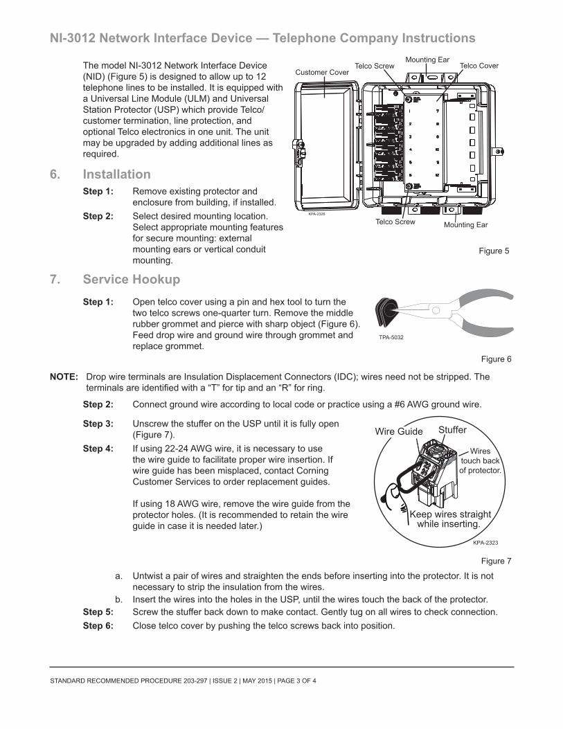
The model NI-3012 Network Interface Device (NID) (Figure 5) is designed to allow up to 12 telephone lines to be installed. It is equipped with a Universal Line Module (ULM) and Universal Station Protector (USP) which provide Telco/customer termination, line protection, and optional Telco electronics in one unit. The unit may be upgraded by adding additional lines as required.
6. InstallationStep 1: Remove existing protector and
enclosure from building, if installed.Step 2: Select desired mounting location.
Select appropriate mounting features for secure mounting: external mounting ears or vertical conduit mounting.
7. Service HookupStep 1: Open telco cover using a pin and hex tool to turn the
two telco screws one-quarter turn. Remove the middle rubber grommet and pierce with sharp object (Figure 6). Feed drop wire and ground wire through grommet and replace grommet.
Figure 6
NOTE: Drop wire terminals are Insulation Displacement Connectors (IDC); wires need not be stripped. The terminals are identified with a “T” for tip and an “R” for ring.
Step 2: Connect ground wire according to local code or practice using a #6 AWG ground wire.
Step 3: Unscrew the stuffer on the USP until it is fully open (Figure 7).
Step 4: If using 22-24 AWG wire, it is necessary to use the wire guide to facilitate proper wire insertion. If wire guide has been misplaced, contact Corning Customer Services to order replacement guides. If using 18 AWG wire, remove the wire guide from the protector holes. (It is recommended to retain the wire guide in case it is needed later.)
Figure 7
a. Untwist a pair of wires and straighten the ends before inserting into the protector. It is not necessary to strip the insulation from the wires.
b. Insert the wires into the holes in the USP, until the wires touch the back of the protector.Step 5: Screw the stuffer back down to make contact. Gently tug on all wires to check connection.Step 6: Close telco cover by pushing the telco screws back into position.
Customer CoverTelco Screw
Telco Screw
Mounting Ear
Mounting Ear
Telco Cover
KPA-2326
Figure 5
TPA-5032
KPA-2323
Keep wires straightwhile inserting.
Wirestouch backof protector.
Wire Guide Stuffer

STANDARD RECOMMENDED PROCEDURE 203-297 | ISSUE 2 | MAy 2015 | PAGE 4 OF 4
Corning Optical Communications LLC • PO Box 489 • Hickory, NC 28603-0489 USA 800-743-2675 • FAX: 828-325-5060 • International: +1-828-901-5000 • www.corning.com/opcomm
Corning Optical Communications reserves the right to improve, enhance, and modify the features and specifications of Corning Optical Communications products without prior notification. A complete listing of the trademarks of Corning Optical Communications is available at www.corning.com/opcomm/trademarks. All other trademarks are the properties of their respective owners. Corning Optical Communications is ISO 9001 certified. © 2009, 2015 Corning Optical Communications. All rights reserved.
8. Upgrade Line Count
To add additional lines, remove the plastic divider and install modules in next available position as required. Replace remaining plastic divider segments in any unused positions.
With the module at 45 degrees and mounting feet aligned with openings in base (Figure 8), press feet into openings and rotate telco terminal end of the module onto the ground bar tang until ground clip is fully engaged.
9. Testing9.1 Continuity of the Telco Wiring
Step 1: With the stuffer in the down position, insert test clips into the center of the test holes on top of the protector in the orientation shown (Figure 9).
Step 2: Test per standard company practices.
9.2 Continuity of the Subscriber WiringStep 1: Open the line module door by sliding the orange latch to the right. Insert
test clips into the test ports on the subscriber line module in the orientation shown for each test to check continuity of the entire line module or to check each line (Figure 10). Move the orange levers to the connected and disconnected positions to check each individual line.
Step 2: Test per standard company practices.Step 3: Slide the orange module latch all the way to the left and close the module
door.
Figure 10
KPA-2324
Press Down
Ground Bar Insert foot of adapter
into opening in NID.
Figure 8k
KPA-2329
Figure 9
CUSTOMER
NETWORK
KPA-2328
Test Subscriber/Customer continuity to each subscriber line inside the premises
with test clips in this position.Toggle the orange lever for each
separate line.
Test Telco/Network continuity from line module to protector with
test clips in this position.