customer satisfaction notification f35 engine connecting ... · customer satisfaction notification...
TRANSCRIPT
© Copyright 2006, DaimlerChrysler Corporation, All Rights Reserved
August 2006
Dealer Service Instructions for:
Customer Satisfaction Notification F35 Engine Connecting Rod Bearing Debris
Effective immediately, all repairs on involved vehicles are to be performed according to this notification. Rapid Response Transmittal RRT #06-025 has been cancelled.
2006 LX and LE Chrysler 300, Dodge Magnum and Charger 2006 CS Chrysler Pacifica NOTE: This notification applies only to the above vehicles equipped with a 3.5L engine (“G” in the 8th VIN position) with engine build date codes from 900586 through 900766. IMPORTANT: Those vehicles that have already had this repair performed, as determined by our warranty records, have been excluded from this notification
The engines in about 14,000 of the above vehicles may have been assembled with sand-like debris on the number two connecting rod bearing journal of the crankshaft. This can cause excessive rod bearing wear and result in engine failure.
Models
IMPORTANT: Some of the involved vehicles may be in dealer vehicle inventory. Dealers should complete this repair on these vehicles before retail delivery. Dealers should also perform this repair on vehicles in for service. Involved vehicles can be determined by using the VIP inquiry process.
Subject
Customer Satisfaction Notification F35 Page 2 Engine Connecting Rod Bearing Debris
The number two connecting rod bearing and crankshaft journal must be inspected. If either the connecting rod bearing or crankshaft journal is damaged, a long block engine must be installed.
Dealers should attempt to minimize customer inconvenience by placing the owner in a loaner vehicle if inspection determines that engine replacement is required and the vehicle must be held overnight.
IMPORTANT: Due to the small number of vehicles requiring engine replacement, engine and gasket packages should only be ordered as determined by the inspection procedure in Section A or Section B. All engine long block assemblies must be ordered through the STAR center. Part Number Quantity Description 68020420AA 1 Engine, 3.5L (LX) Long Block 68020419AA 1 Engine, 3.5L (CS) Long Block Part Number Description CEA0F352 LX Long Block Parts Package Each package contains the following components: Quantity Description
1 Gasket, EGR Valve to Cylinder Head 1 Gasket, EGR Valve to EGR tube 2 Gasket, Exhaust Manifold to Cylinder Head 8 Bolt, Drive Plate to Crankshaft
Repair
Alternate Transportation
Parts Information
Customer Satisfaction Notification F35 Page 3 Engine Connecting Rod Bearing Debris
Part Number Description CEA0F351 CS Long Block Parts Package Each package contains the following components: Quantity Description
1 Gasket, EGR Valve to Cylinder Head 1 Gasket, EGR Valve to EGR Tube 2 Gasket, Exhaust Manifold to Cylinder Head 1 Gasket, Crossover pipe, Crossover to Front Exhaust Manifold 1 Gasket, Crossover pipe, Crossover to Rear Exhaust Manifold 1 Gasket, Exhaust Manifold to Front Catalytic Converter 8 Bolt, Drive Plate to Crankshaft
The following existing special tools may be required to perform this repair: Tool Number Description
C-4685-C1 Screw, Forcing 6792 Installer, Crank Sprocket 9365 Holding Fixture, Damper L-4407A Puller, Gear 8874 CS Suspension Cradle Fixture CH9401 StarSCAN Tool CH9404 StarSCAN Vehicle Cable 8631 CS Steering Coupling Pin Removal 8874 CS Suspension Cradle Support Fixture 8534 Engine Lift Kit
Parts Information (Continued)
Special Tools
Customer Satisfaction Notification F35 Page 4 Engine Connecting Rod Bearing Debris
A. LX (RWD and AWD) Engine Inspection 1. Open the trunk lid or tailgate.
2. Raise the cargo floor panel to access the battery.
3. Disconnect the battery.
NOTE: To enhance customer satisfaction, remember to reset the clock when you have completed the service procedure.
4. Open the hood.
5. Remove the engine oil dipstick.
6. Remove the generator upper support bracket.
7. Remove the dipstick tube mounting bolt and remove the dipstick tube from the engine oil pan.
8. Lock the steering wheel in the straight ahead position.
9. Raise the vehicle on a suitable hoist.
10. Remove the lower plastic splash shield from under the engine.
11. Drain engine oil and remove the engine oil filter.
12. Install the engine oil drain plug into the engine oil pan and tighten.
Service Procedure
Customer Satisfaction Notification F35 Page 5 Engine Connecting Rod Bearing Debris
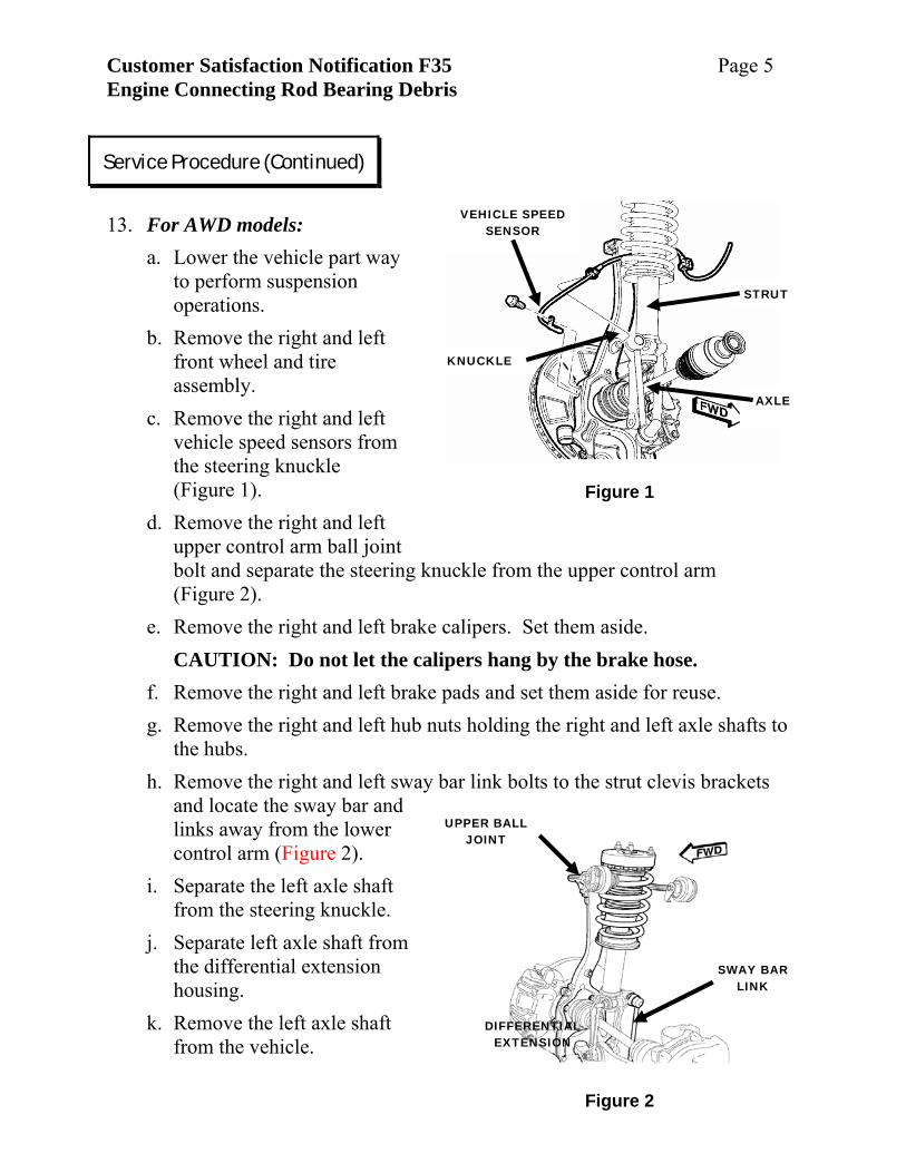
Figure 1
VEHICLE SPEED SENSOR
STRUT
KNUCKLE
AXLE
Figure 2
UPPER BALL JOINT
SWAY BAR LINK
DIFFERENTIAL EXTENSION
13. For AWD models:
a. Lower the vehicle part way to perform suspension operations.
b. Remove the right and left front wheel and tire assembly.
c. Remove the right and left vehicle speed sensors from the steering knuckle (Figure 1).
d. Remove the right and left upper control arm ball joint bolt and separate the steering knuckle from the upper control arm (Figure 2).
e. Remove the right and left brake calipers. Set them aside. CAUTION: Do not let the calipers hang by the brake hose.
f. Remove the right and left brake pads and set them aside for reuse. g. Remove the right and left hub nuts holding the right and left axle shafts to
the hubs. h. Remove the right and left sway bar link bolts to the strut clevis brackets
and locate the sway bar and links away from the lower control arm (Figure 2).
i. Separate the left axle shaft from the steering knuckle.
j. Separate left axle shaft from the differential extension housing.
k. Remove the left axle shaft from the vehicle.
Service Procedure (Continued)
Customer Satisfaction Notification F35 Page 6 Engine Connecting Rod Bearing Debris
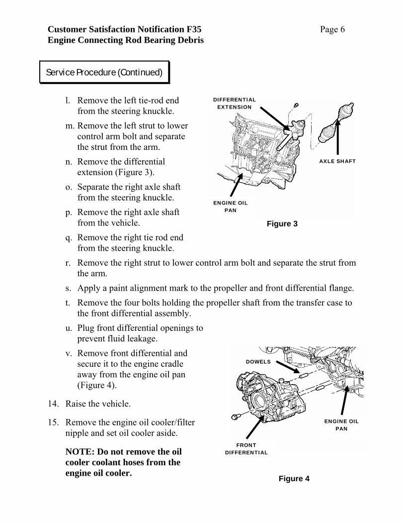
Figure 4
FRONT DIFFERENTIAL
DOWELS
ENGINE OIL PAN
Figure 3
ENGINE OIL PAN
AXLE SHAFT
DIFFERENTIAL EXTENSION
l. Remove the left tie-rod end
from the steering knuckle. m. Remove the left strut to lower
control arm bolt and separate the strut from the arm.
n. Remove the differential extension (Figure 3).
o. Separate the right axle shaft from the steering knuckle.
p. Remove the right axle shaft from the vehicle.
q. Remove the right tie rod end from the steering knuckle.
r. Remove the right strut to lower control arm bolt and separate the strut from the arm.
s. Apply a paint alignment mark to the propeller and front differential flange. t. Remove the four bolts holding the propeller shaft from the transfer case to
the front differential assembly. u. Plug front differential openings to
prevent fluid leakage. v. Remove front differential and
secure it to the engine cradle away from the engine oil pan (Figure 4).
14. Raise the vehicle.
15. Remove the engine oil cooler/filter nipple and set oil cooler aside.
NOTE: Do not remove the oil cooler coolant hoses from the engine oil cooler.
Service Procedure (Continued)
Customer Satisfaction Notification F35 Page 7 Engine Connecting Rod Bearing Debris
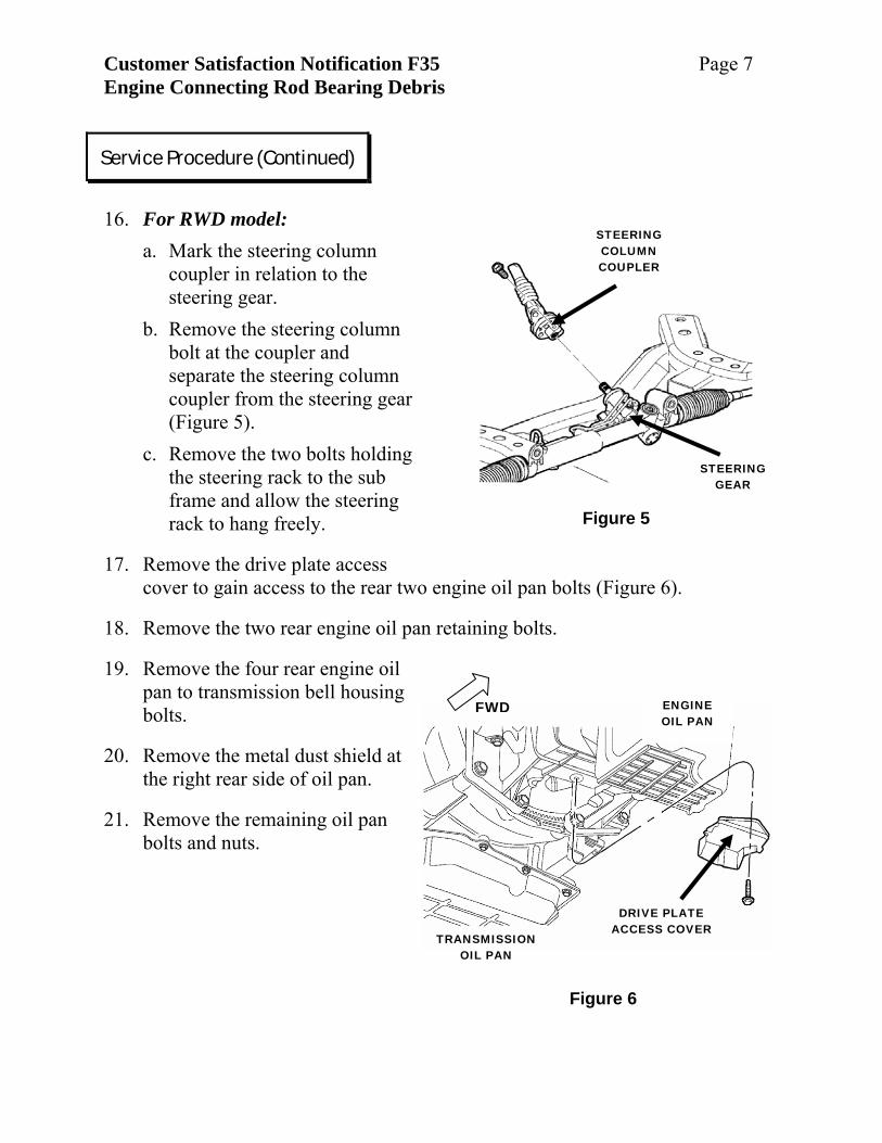
Figure 6
ENGINE OIL PAN
TRANSMISSION OIL PAN
DRIVE PLATE ACCESS COVER
FWD
Figure 5
STEERING COLUMN COUPLER
STEERING GEAR
16. For RWD model:
a. Mark the steering column coupler in relation to the steering gear.
b. Remove the steering column bolt at the coupler and separate the steering column coupler from the steering gear (Figure 5).
c. Remove the two bolts holding the steering rack to the sub frame and allow the steering rack to hang freely.
17. Remove the drive plate access cover to gain access to the rear two engine oil pan bolts (Figure 6).
18. Remove the two rear engine oil pan retaining bolts.
19. Remove the four rear engine oil pan to transmission bell housing bolts.
20. Remove the metal dust shield at the right rear side of oil pan.
21. Remove the remaining oil pan bolts and nuts.
Service Procedure (Continued)
Customer Satisfaction Notification F35 Page 8 Engine Connecting Rod Bearing Debris
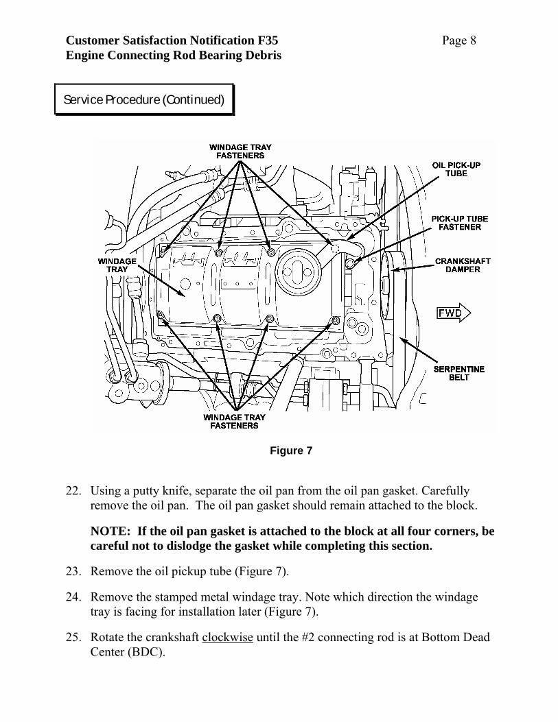
Figure 7
22. Using a putty knife, separate the oil pan from the oil pan gasket. Carefully
remove the oil pan. The oil pan gasket should remain attached to the block.
NOTE: If the oil pan gasket is attached to the block at all four corners, be careful not to dislodge the gasket while completing this section.
23. Remove the oil pickup tube (Figure 7).
24. Remove the stamped metal windage tray. Note which direction the windage tray is facing for installation later (Figure 7).
25. Rotate the crankshaft clockwise until the #2 connecting rod is at Bottom Dead Center (BDC).
Service Procedure (Continued)
Customer Satisfaction Notification F35 Page 9 Engine Connecting Rod Bearing Debris
PAINT MARKS
CONNECTING ROD
Figure 8
Figure 9 – Good Bearing
OVAL OIL HOLE WITH CLEAN EDGES
EDGE WEAR ACCEPTABLE
FINE MACHINING LINES AND ALUMINIUM FINISH
Figure 10 – Failed Bearing
BRONZE-COPPER COLOR
NO FINE MACHINING LINES SURFACE IS TORN & PITTED
OVAL OIL HOLE EDGE HAS FINE
BURRS
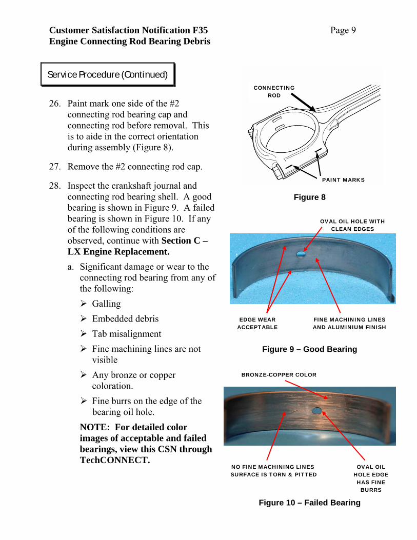
26. Paint mark one side of the #2
connecting rod bearing cap and connecting rod before removal. This is to aide in the correct orientation during assembly (Figure 8).
27. Remove the #2 connecting rod cap.
28. Inspect the crankshaft journal and connecting rod bearing shell. A good bearing is shown in Figure 9. A failed bearing is shown in Figure 10. If any of the following conditions are observed, continue with Section C – LX Engine Replacement. a. Significant damage or wear to the
connecting rod bearing from any of the following:
Galling Embedded debris Tab misalignment Fine machining lines are not visible
Any bronze or copper coloration.
Fine burrs on the edge of the bearing oil hole.
NOTE: For detailed color images of acceptable and failed bearings, view this CSN through TechCONNECT.
Service Procedure (Continued)
Customer Satisfaction Notification F35 Page 10 Engine Connecting Rod Bearing Debris
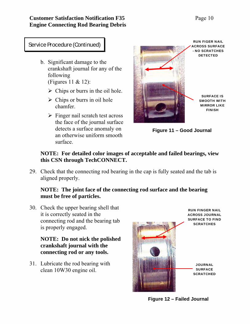
Figure 11 – Good Journal
RUN FIGER NAIL ACROSS SURFACE - NO SCRATCHES
DETECTED
SURFACE IS SMOOTH WITH MIRROR LIKE
FINISH
Figure 12 – Failed Journal
RUN FINGER NAIL ACROSS JOURNAL SURFACE TO FIND
SCRATCHES
JOURNAL SURFACE
SCRATCHED
b. Significant damage to the
crankshaft journal for any of the following (Figures 11 & 12):
Chips or burrs in the oil hole. Chips or burrs in oil hole chamfer.
Finger nail scratch test across the face of the journal surface detects a surface anomaly on an otherwise uniform smooth surface.
NOTE: For detailed color images of acceptable and failed bearings, view this CSN through TechCONNECT.
29. Check that the connecting rod bearing in the cap is fully seated and the tab is aligned properly.
NOTE: The joint face of the connecting rod surface and the bearing must be free of particles.
30. Check the upper bearing shell that it is correctly seated in the connecting rod and the bearing tab is properly engaged.
NOTE: Do not nick the polished crankshaft journal with the connecting rod or any tools.
31. Lubricate the rod bearing with clean 10W30 engine oil.
Service Procedure (Continued)
Customer Satisfaction Notification F35 Page 11 Engine Connecting Rod Bearing Debris
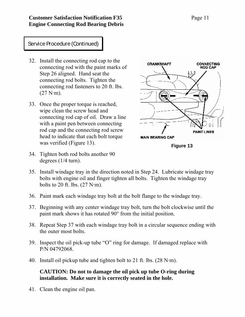
Figure 13
32. Install the connecting rod cap to the
connecting rod with the paint marks of Step 26 aligned. Hand seat the connecting rod bolts. Tighten the connecting rod fasteners to 20 ft. lbs. (27 N·m).
33. Once the proper torque is reached, wipe clean the screw head and connecting rod cap of oil. Draw a line with a paint pen between connecting rod cap and the connecting rod screw head to indicate that each bolt torque was verified (Figure 13).
34. Tighten both rod bolts another 90 degrees (1/4 turn).
35. Install windage tray in the direction noted in Step 24. Lubricate windage tray bolts with engine oil and finger tighten all bolts. Tighten the windage tray bolts to 20 ft. lbs. (27 N·m).
36. Paint mark each windage tray bolt at the bolt flange to the windage tray.
37. Beginning with any center windage tray bolt, turn the bolt clockwise until the paint mark shows it has rotated 90° from the initial position.
38. Repeat Step 37 with each windage tray bolt in a circular sequence ending with the outer most bolts.
39. Inspect the oil pick-up tube “O” ring for damage. If damaged replace with P/N 04792068.
40. Install oil pickup tube and tighten bolt to 21 ft. lbs. (28 N·m).
CAUTION: Do not to damage the oil pick up tube O-ring during installation. Make sure it is correctly seated in the hole.
41. Clean the engine oil pan.
Service Procedure (Continued)
Customer Satisfaction Notification F35 Page 12 Engine Connecting Rod Bearing Debris
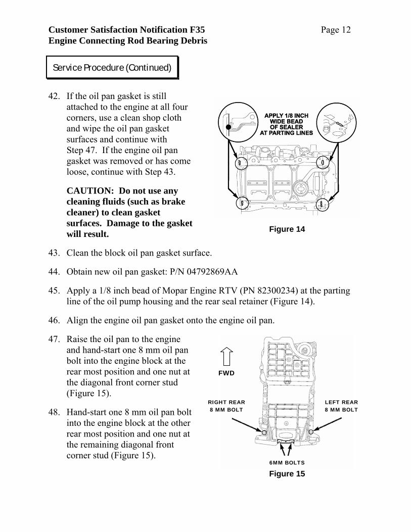
Figure 14
RIGHT REAR 8 MM BOLT
LEFT REAR 8 MM BOLT
6MM BOLTS
FWD
Figure 15
42. If the oil pan gasket is still
attached to the engine at all four corners, use a clean shop cloth and wipe the oil pan gasket surfaces and continue with Step 47. If the engine oil pan gasket was removed or has come loose, continue with Step 43.
CAUTION: Do not use any cleaning fluids (such as brake cleaner) to clean gasket surfaces. Damage to the gasket will result.
43. Clean the block oil pan gasket surface.
44. Obtain new oil pan gasket: P/N 04792869AA
45. Apply a 1/8 inch bead of Mopar Engine RTV (PN 82300234) at the parting line of the oil pump housing and the rear seal retainer (Figure 14).
46. Align the engine oil pan gasket onto the engine oil pan.
47. Raise the oil pan to the engine and hand-start one 8 mm oil pan bolt into the engine block at the rear most position and one nut at the diagonal front corner stud (Figure 15).
48. Hand-start one 8 mm oil pan bolt into the engine block at the other rear most position and one nut at the remaining diagonal front corner stud (Figure 15).
Service Procedure (Continued)
Customer Satisfaction Notification F35 Page 13 Engine Connecting Rod Bearing Debris
Figure 16
ENGINE OIL PAN
TRANSMISSION OIL PAN
DRIVE PLATE ACCESS COVER
FWD
LOWER BOLTS
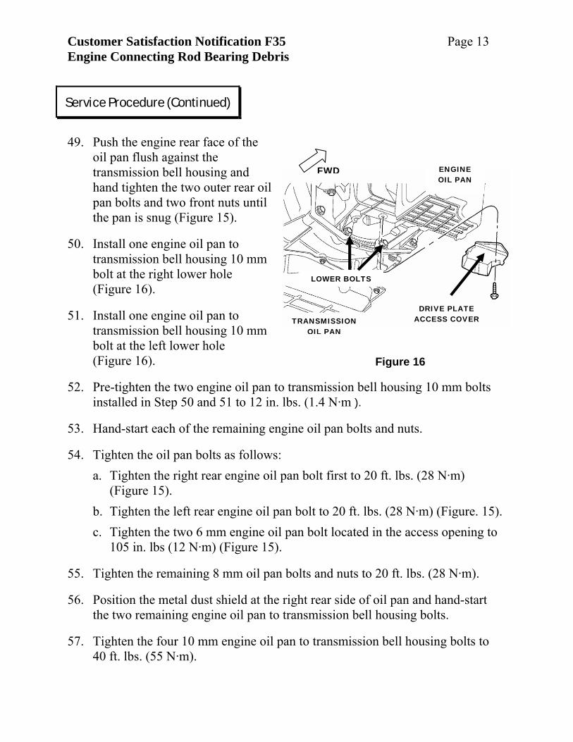
49. Push the engine rear face of the
oil pan flush against the transmission bell housing and hand tighten the two outer rear oil pan bolts and two front nuts until the pan is snug (Figure 15).
50. Install one engine oil pan to transmission bell housing 10 mm bolt at the right lower hole (Figure 16).
51. Install one engine oil pan to transmission bell housing 10 mm bolt at the left lower hole (Figure 16).
52. Pre-tighten the two engine oil pan to transmission bell housing 10 mm bolts installed in Step 50 and 51 to 12 in. lbs. (1.4 N·m ).
53. Hand-start each of the remaining engine oil pan bolts and nuts.
54. Tighten the oil pan bolts as follows: a. Tighten the right rear engine oil pan bolt first to 20 ft. lbs. (28 N·m)
(Figure 15). b. Tighten the left rear engine oil pan bolt to 20 ft. lbs. (28 N·m) (Figure. 15). c. Tighten the two 6 mm engine oil pan bolt located in the access opening to
105 in. lbs (12 N·m) (Figure 15).
55. Tighten the remaining 8 mm oil pan bolts and nuts to 20 ft. lbs. (28 N·m).
56. Position the metal dust shield at the right rear side of oil pan and hand-start the two remaining engine oil pan to transmission bell housing bolts.
57. Tighten the four 10 mm engine oil pan to transmission bell housing bolts to 40 ft. lbs. (55 N·m).
Service Procedure (Continued)
Customer Satisfaction Notification F35 Page 14 Engine Connecting Rod Bearing Debris
Figure 17
FRONT DIFFERENTIAL
DOWELS
ENGINE OIL PAN
58. Install the torque converter access cover (Figure 16) and tighten the fastener to
97 in. lbs. (11 N·m).
59. Wipe clean both the upper engine oil cooler sealing “O” ring and the oil filter sealing surface.
60. Position oil cooler to fitting on oil pan. The notch in the engine oil pan oil cooler pad must fit into the cut-out of the oil cooler.
61. While holding the engine oil cooler in position, install the oil cooler/filter nipple and tighten to 45 ft. lbs. (61 N·m).
NOTE: Do not over tighten. Damage to the oil cooler will occur.
62. Install a new oil filter and tighten to 106 in. lbs. (12 N·m).
63. For AWD models:
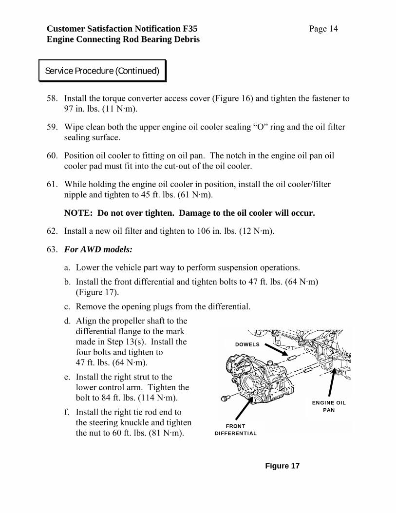
a. Lower the vehicle part way to perform suspension operations. b. Install the front differential and tighten bolts to 47 ft. lbs. (64 N·m)
(Figure 17). c. Remove the opening plugs from the differential. d. Align the propeller shaft to the
differential flange to the mark made in Step 13(s). Install the four bolts and tighten to 47 ft. lbs. (64 N·m).
e. Install the right strut to the lower control arm. Tighten the bolt to 84 ft. lbs. (114 N·m).
f. Install the right tie rod end to the steering knuckle and tighten the nut to 60 ft. lbs. (81 N·m).
Service Procedure (Continued)
Customer Satisfaction Notification F35 Page 15 Engine Connecting Rod Bearing Debris
Figure 19
UPPER BALL JOINT
SWAY BAR LINK
Figure 18
ENGINE OIL PAN
AXLE SHAFT
DIFFERENTIAL EXTENSION
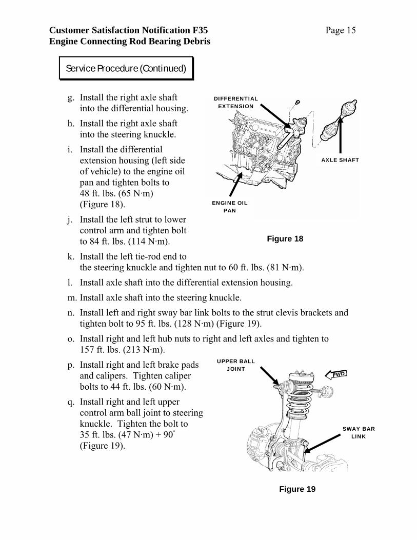
g. Install the right axle shaft
into the differential housing. h. Install the right axle shaft
into the steering knuckle. i. Install the differential
extension housing (left side of vehicle) to the engine oil pan and tighten bolts to 48 ft. lbs. (65 N·m) (Figure 18).
j. Install the left strut to lower control arm and tighten bolt to 84 ft. lbs. (114 N·m).
k. Install the left tie-rod end to the steering knuckle and tighten nut to 60 ft. lbs. (81 N·m).
l. Install axle shaft into the differential extension housing. m. Install axle shaft into the steering knuckle. n. Install left and right sway bar link bolts to the strut clevis brackets and
tighten bolt to 95 ft. lbs. (128 N·m) (Figure 19). o. Install right and left hub nuts to right and left axles and tighten to
157 ft. lbs. (213 N·m). p. Install right and left brake pads
and calipers. Tighten caliper bolts to 44 ft. lbs. (60 N·m).
q. Install right and left upper control arm ball joint to steering knuckle. Tighten the bolt to 35 ft. lbs. (47 N·m) + 90◦ (Figure 19).
Service Procedure (Continued)
Customer Satisfaction Notification F35 Page 16 Engine Connecting Rod Bearing Debris
Figure 20
VEHICLE SPEED SENSOR
STRUT
KNUCKLE
AXLE
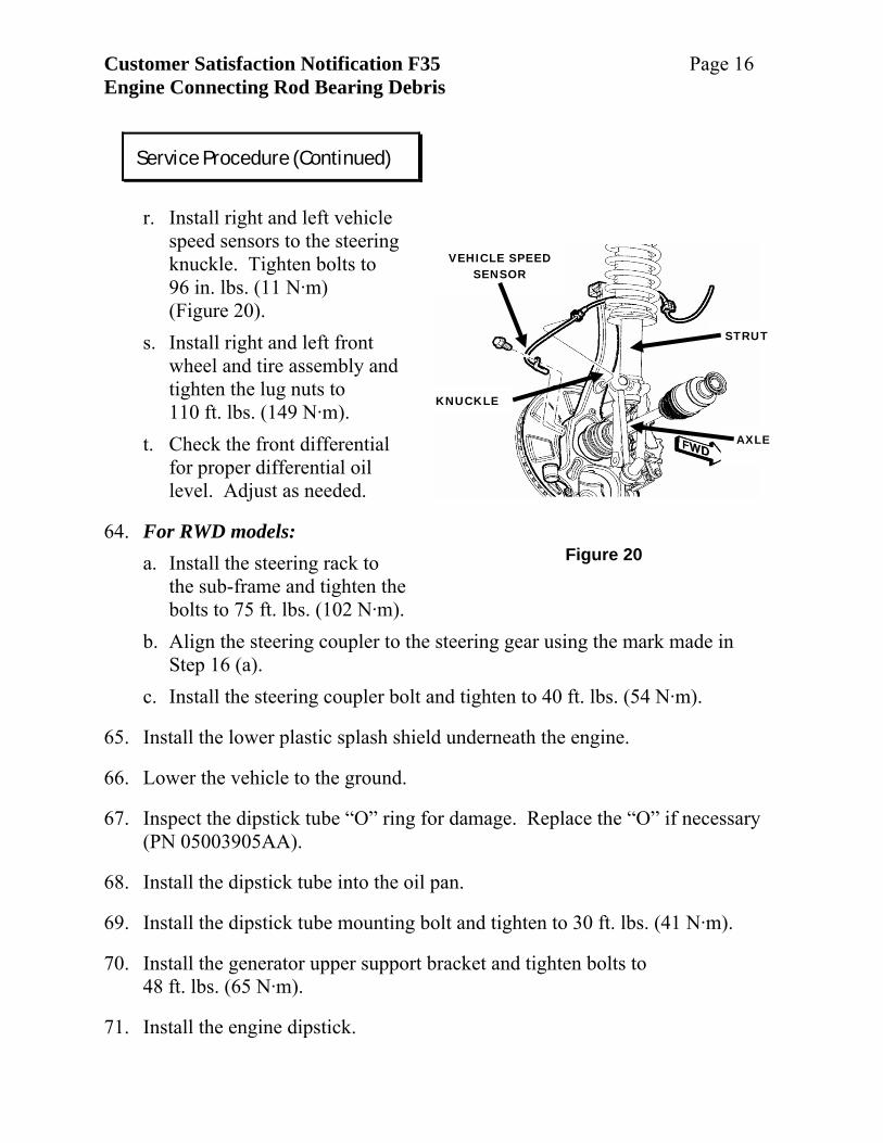
r. Install right and left vehicle
speed sensors to the steering knuckle. Tighten bolts to 96 in. lbs. (11 N·m) (Figure 20).
s. Install right and left front wheel and tire assembly and tighten the lug nuts to 110 ft. lbs. (149 N·m).
t. Check the front differential for proper differential oil level. Adjust as needed.
64. For RWD models: a. Install the steering rack to
the sub-frame and tighten the bolts to 75 ft. lbs. (102 N·m).
b. Align the steering coupler to the steering gear using the mark made in Step 16 (a).
c. Install the steering coupler bolt and tighten to 40 ft. lbs. (54 N·m).
65. Install the lower plastic splash shield underneath the engine.
66. Lower the vehicle to the ground.
67. Inspect the dipstick tube “O” ring for damage. Replace the “O” if necessary (PN 05003905AA).
68. Install the dipstick tube into the oil pan.
69. Install the dipstick tube mounting bolt and tighten to 30 ft. lbs. (41 N·m).
70. Install the generator upper support bracket and tighten bolts to 48 ft. lbs. (65 N·m).
71. Install the engine dipstick.
Service Procedure (Continued)
Customer Satisfaction Notification F35 Page 17 Engine Connecting Rod Bearing Debris
72. Install six new quarts of 10W30 engine oil into the engine.
73. Connect the battery.
74. Verify the seating of the cargo floor panel.
75. Start the vehicle and inspect for leaks.
76. Return vehicle to the customer. B. CS (FWD & AWD) Engine Inspection 1. Open the hood.
2. Disconnect the battery.
NOTE: To enhance customer satisfaction, remember to reset the clock when you have completed the service procedure.
3. Remove engine trim cover.
4. Remove engine oil dipstick.
5. Remove dipstick tube mounting bolt and remove the dipstick tube from the engine oil pan.
6. Remove serpentine belt.
7. Raise the vehicle on a suitable hoist.
8. Remove the right wheel well lower splash shield.
9. Remove the four air conditioning compressor bolts. Set the compressor aside and secure.
10. Remove the air conditioning compressor mounting bracket.
11. Remove the power steering return hose bracket and set aside.
Service Procedure (Continued)
Customer Satisfaction Notification F35 Page 18 Engine Connecting Rod Bearing Debris
Figure 21 – AWD Only
ENGINE OIL PAN
STRUCTURAL COLLAR BRACKET
BELL HOUSING
Figure 22
ACCESS COVER
ENGINE OIL PAN
BELL HOUSING
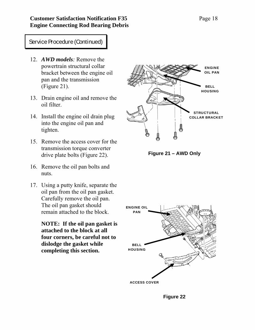
12. AWD models: Remove the
powertrain structural collar bracket between the engine oil pan and the transmission (Figure 21).
13. Drain engine oil and remove the oil filter.
14. Install the engine oil drain plug into the engine oil pan and tighten.
15. Remove the access cover for the transmission torque converter drive plate bolts (Figure 22).
16. Remove the oil pan bolts and nuts.
17. Using a putty knife, separate the oil pan from the oil pan gasket. Carefully remove the oil pan. The oil pan gasket should remain attached to the block.
NOTE: If the oil pan gasket is attached to the block at all four corners, be careful not to dislodge the gasket while completing this section.
Service Procedure (Continued)
Customer Satisfaction Notification F35 Page 19 Engine Connecting Rod Bearing Debris
Figure 23 - Typical
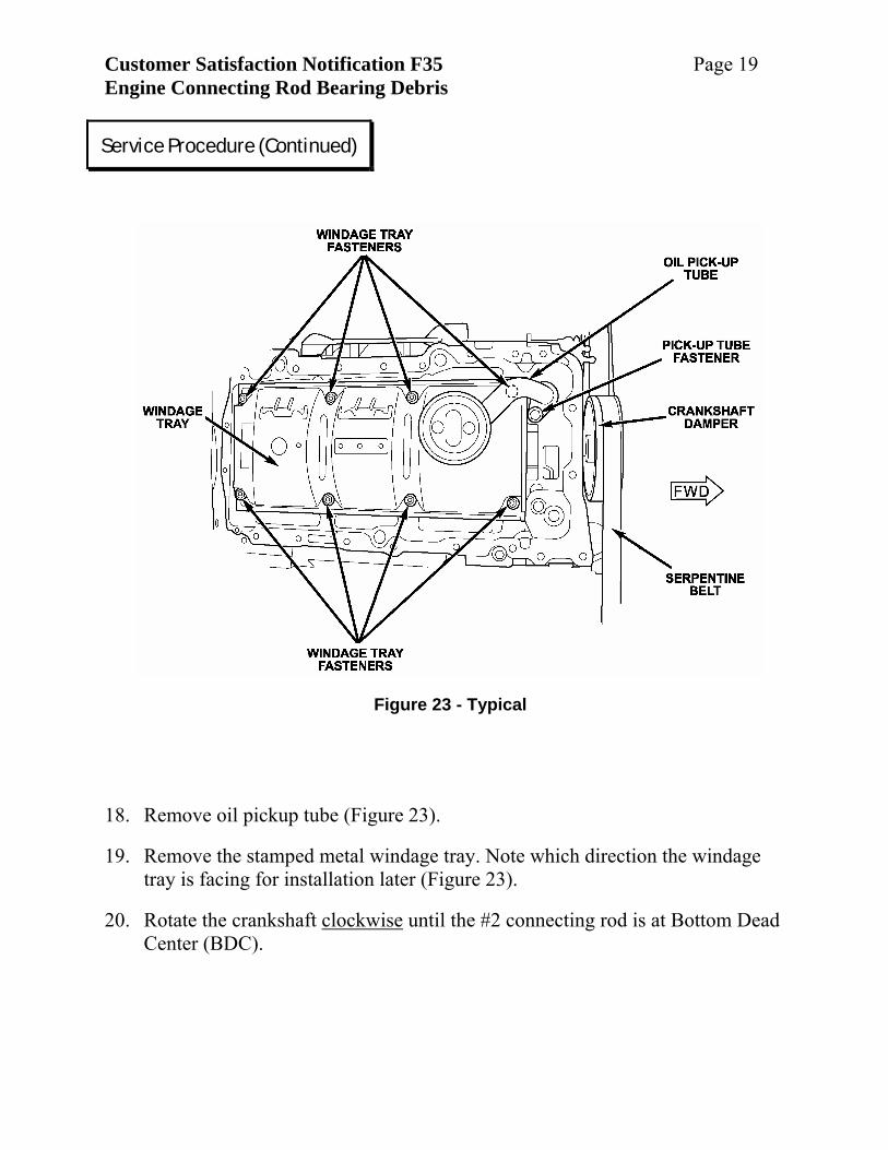
18. Remove oil pickup tube (Figure 23).
19. Remove the stamped metal windage tray. Note which direction the windage tray is facing for installation later (Figure 23).
20. Rotate the crankshaft clockwise until the #2 connecting rod is at Bottom Dead Center (BDC).
Service Procedure (Continued)
Customer Satisfaction Notification F35 Page 20 Engine Connecting Rod Bearing Debris
PAINT MARKS
CONNECTING ROD
Figure 24
Figure 26 – Failed Bearing
BRONZE-COPPER COLOR
NO FINE MACHINING LINES SURFACE IS TORN & PITTED
OVAL OIL HOLE EDGE HAS FINE
BURRS
Figure 25 – Good Bearing
OVAL OIL HOLE WITH CLEAN EDGES
EDGE WEAR ACCEPTABLE
FINE MACHINING LINES AND ALUMINIUM FINISH
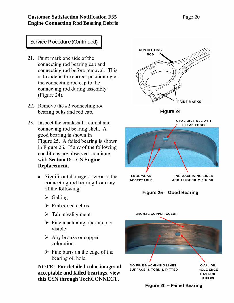
21. Paint mark one side of the
connecting rod bearing cap and connecting rod before removal. This is to aide in the correct positioning of the connecting rod cap to the connecting rod during assembly (Figure 24).
22. Remove the #2 connecting rod bearing bolts and rod cap.
23. Inspect the crankshaft journal and connecting rod bearing shell. A good bearing is shown in Figure 25. A failed bearing is shown in Figure 26. If any of the following conditions are observed, continue with Section D – CS Engine Replacement.
a. Significant damage or wear to the connecting rod bearing from any of the following:
Galling Embedded debris Tab misalignment Fine machining lines are not visible
Any bronze or copper coloration.
Fine burrs on the edge of the bearing oil hole.
NOTE: For detailed color images of acceptable and failed bearings, view this CSN through TechCONNECT.
Service Procedure (Continued)
Customer Satisfaction Notification F35 Page 21 Engine Connecting Rod Bearing Debris
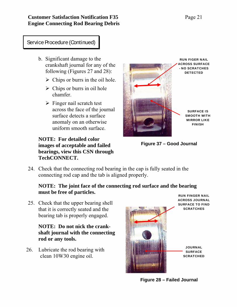
Figure 28 – Failed Journal
RUN FINGER NAIL ACROSS JOURNAL SURFACE TO FIND
SCRATCHES
JOURNAL SURFACE
SCRATCHED
Figure 37 – Good Journal
RUN FIGER NAIL ACROSS SURFACE - NO SCRATCHES
DETECTED
SURFACE IS SMOOTH WITH MIRROR LIKE
FINISH
b. Significant damage to the
crankshaft journal for any of the following (Figures 27 and 28):
Chips or burrs in the oil hole. Chips or burrs in oil hole chamfer.
Finger nail scratch test across the face of the journal surface detects a surface anomaly on an otherwise uniform smooth surface.
NOTE: For detailed color images of acceptable and failed bearings, view this CSN through TechCONNECT.
24. Check that the connecting rod bearing in the cap is fully seated in the connecting rod cap and the tab is aligned properly.
NOTE: The joint face of the connecting rod surface and the bearing must be free of particles.
25. Check that the upper bearing shell that it is correctly seated and the bearing tab is properly engaged.
NOTE: Do not nick the crank-shaft journal with the connecting rod or any tools.
26. Lubricate the rod bearing with clean 10W30 engine oil.
Service Procedure (Continued)
Customer Satisfaction Notification F35 Page 22 Engine Connecting Rod Bearing Debris
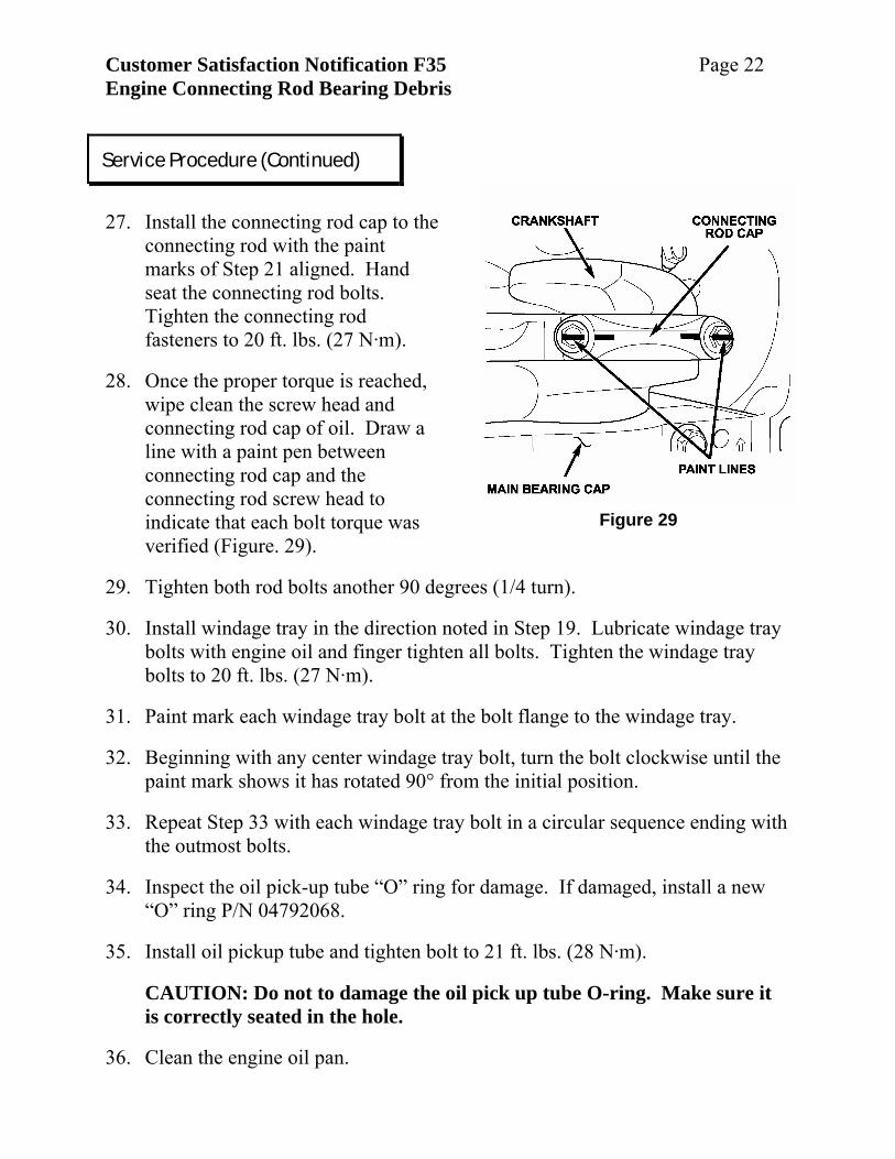
Figure 29
27. Install the connecting rod cap to the
connecting rod with the paint marks of Step 21 aligned. Hand seat the connecting rod bolts. Tighten the connecting rod fasteners to 20 ft. lbs. (27 N·m).
28. Once the proper torque is reached, wipe clean the screw head and connecting rod cap of oil. Draw a line with a paint pen between connecting rod cap and the connecting rod screw head to indicate that each bolt torque was verified (Figure. 29).
29. Tighten both rod bolts another 90 degrees (1/4 turn).
30. Install windage tray in the direction noted in Step 19. Lubricate windage tray bolts with engine oil and finger tighten all bolts. Tighten the windage tray bolts to 20 ft. lbs. (27 N·m).
31. Paint mark each windage tray bolt at the bolt flange to the windage tray.
32. Beginning with any center windage tray bolt, turn the bolt clockwise until the paint mark shows it has rotated 90° from the initial position.
33. Repeat Step 33 with each windage tray bolt in a circular sequence ending with the outmost bolts.
34. Inspect the oil pick-up tube “O” ring for damage. If damaged, install a new “O” ring P/N 04792068.
35. Install oil pickup tube and tighten bolt to 21 ft. lbs. (28 N·m).
CAUTION: Do not to damage the oil pick up tube O-ring. Make sure it is correctly seated in the hole.
36. Clean the engine oil pan.
Service Procedure (Continued)
Customer Satisfaction Notification F35 Page 23 Engine Connecting Rod Bearing Debris
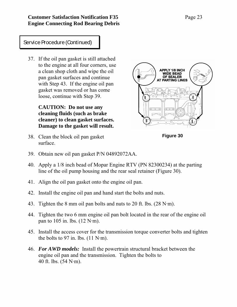
Figure 30
37. If the oil pan gasket is still attached
to the engine at all four corners, use a clean shop cloth and wipe the oil pan gasket surfaces and continue with Step 43. If the engine oil pan gasket was removed or has come loose, continue with Step 39.
CAUTION: Do not use any cleaning fluids (such as brake cleaner) to clean gasket surfaces. Damage to the gasket will result.
38. Clean the block oil pan gasket surface.
39. Obtain new oil pan gasket P/N 04892072AA.
40. Apply a 1/8 inch bead of Mopar Engine RTV (PN 82300234) at the parting line of the oil pump housing and the rear seal retainer (Figure 30).
41. Align the oil pan gasket onto the engine oil pan.
42. Install the engine oil pan and hand start the bolts and nuts.
43. Tighten the 8 mm oil pan bolts and nuts to 20 ft. lbs. (28 N·m).
44. Tighten the two 6 mm engine oil pan bolt located in the rear of the engine oil pan to 105 in. lbs. (12 N·m).
45. Install the access cover for the transmission torque converter bolts and tighten the bolts to 97 in. lbs. (11 N·m).
46. For AWD models: Install the powertrain structural bracket between the engine oil pan and the transmission. Tighten the bolts to 40 ft. lbs. (54 N·m).
Service Procedure (Continued)
Customer Satisfaction Notification F35 Page 24 Engine Connecting Rod Bearing Debris
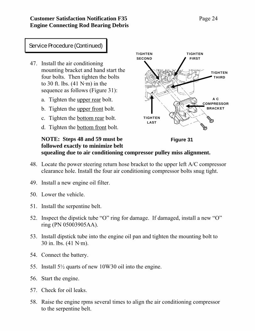
Figure 31
TIGHTEN FIRST
TIGHTEN SECOND
TIGHTEN LAST
A C COMPRESSOR
BRACKET
TIGHTEN THIRD
47. Install the air conditioning
mounting bracket and hand start the four bolts. Then tighten the bolts to 30 ft. lbs. (41 N·m) in the sequence as follows (Figure 31): a. Tighten the upper rear bolt. b. Tighten the upper front bolt. c. Tighten the bottom rear bolt. d. Tighten the bottom front bolt.
NOTE: Steps 48 and 59 must be followed exactly to minimize belt squealing due to air conditioning compressor pulley miss alignment.
48. Locate the power steering return hose bracket to the upper left A/C compressor clearance hole. Install the four air conditioning compressor bolts snug tight.
49. Install a new engine oil filter.
50. Lower the vehicle.
51. Install the serpentine belt.
52. Inspect the dipstick tube “O” ring for damage. If damaged, install a new “O” ring (PN 05003905AA).
53. Install dipstick tube into the engine oil pan and tighten the mounting bolt to 30 in. lbs. (41 N·m).
54. Connect the battery.
55. Install 5½ quarts of new 10W30 oil into the engine.
56. Start the engine.
57. Check for oil leaks.
58. Raise the engine rpms several times to align the air conditioning compressor to the serpentine belt.
Service Procedure (Continued)
Customer Satisfaction Notification F35 Page 25 Engine Connecting Rod Bearing Debris
Figure 32
COWL GRILL
STRUT TOWER STRUCTURAL
BAR FWD
59. Raise the vehicle while the engine is idling.
60. Carefully tighten ONLY THE LOWER TWO air conditioning compressor bolts to 200 in. lbs. (23 N·m).
WARNING: Keep hands and tools away from the moving serpentine belt while tightening the air conditioning compressor mounting bolts.
61. Lower the vehicle and turn off the ignition.
62. Raise the vehicle and torque the four bolts to the air conditioning compressor to 200 in. lbs. (23 N·m).
63. Install the right wheel well lower splash shield.
64. Lower the vehicle.
65. Install engine trim cover.
66. Return vehicle to the customer. C. LX (AWD and RWD) Engine Replacement 1. Install the #2 connecting rod cap
and finger start the connecting rod bolts.
2. Install the engine oil pan with four bolts and snug tight.
3. Lower the vehicle.
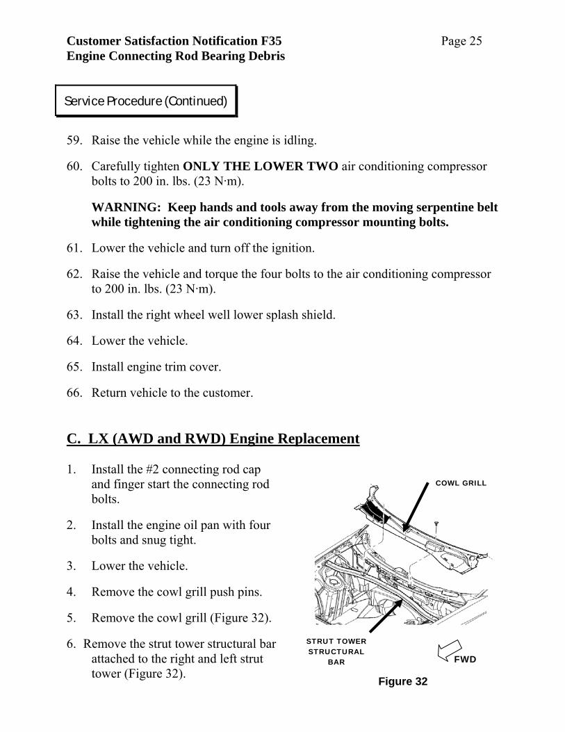
4. Remove the cowl grill push pins.
5. Remove the cowl grill (Figure 32).
6. Remove the strut tower structural bar attached to the right and left strut tower (Figure 32).
Service Procedure (Continued)
Customer Satisfaction Notification F35 Page 26 Engine Connecting Rod Bearing Debris
7. Remove the engine air inlet filter box.
8. Remove the tube connecting the air filter box to the throttle body.
9. Remove the Positive Crankcase Ventilation hose.
10. Remove the EGR tube.
11. Remove the brake booster and other vacuum lines from the intake manifold.
12. Disconnect the electrical harness from throttle body.
13. Disconnect the electrical lead to the MAP sensor.
14. Remove the upper intake plenum from the engine, its brackets and pencil braces.
15. Remove the engine foam silencer pad from the top of the engine.
16. Disconnect the electrical connections to the generator.
17. Remove the generator.
18. Place disposable towels underneath the fuel line disconnect at the engine.
19. Disconnect the fuel line at the engine disconnect.
20. Cap the fuel supply line opening.
21. Cap the engine fuel line opening.
22. Remove the radiator cap, drain the engine coolant and save for reuse.
23. Discharge the air conditioning system using an appropriate refrigerant recovery system.
24. Disconnect the left oxygen sensor from the engine wiring harness.
25. Disconnect the left side ground strap assembly on the left engine valve cover and at the cylinder head.
26. Disconnect the right side oxygen sensor from the engine electrical harness.
Service Procedure (Continued)
Customer Satisfaction Notification F35 Page 27 Engine Connecting Rod Bearing Debris
27. Disconnect the engine harness from the IP chassis harness.
28. Remove the upper radiator hose completely.
29. Remove the serpentine belt.
30. Remove the power steering pump and set it aside.
31. Remove the lower coolant hose from the engine.
32. Disconnect the high pressure line to the air conditioning compressor.
33. Using clean caps, plug the end of the high pressure air conditioning line and the open port in the air conditioning compressor.
34. Disconnect the low pressure line to the air condition compressor.
35. Using clean caps, plug the end of the low pressure air conditioning line and the open port in the air conditioning compressor.
36. Remove the coolant recovery bottle hose.
37. Disconnect heater hose from the rear of the engine.
38. Remove the engine wire harness / support bracket from the top of the transmission bell housing.
Service Procedure (Continued)
Customer Satisfaction Notification F35 Page 28 Engine Connecting Rod Bearing Debris
TRANSMISSION BELL HOUSING
GROUND BLOCK HEATER
(IF SO EQUIPPED)
NEGATIVE BATTERY
CABLE
ENGINE INTAKE MANIFOLD
Figure 33
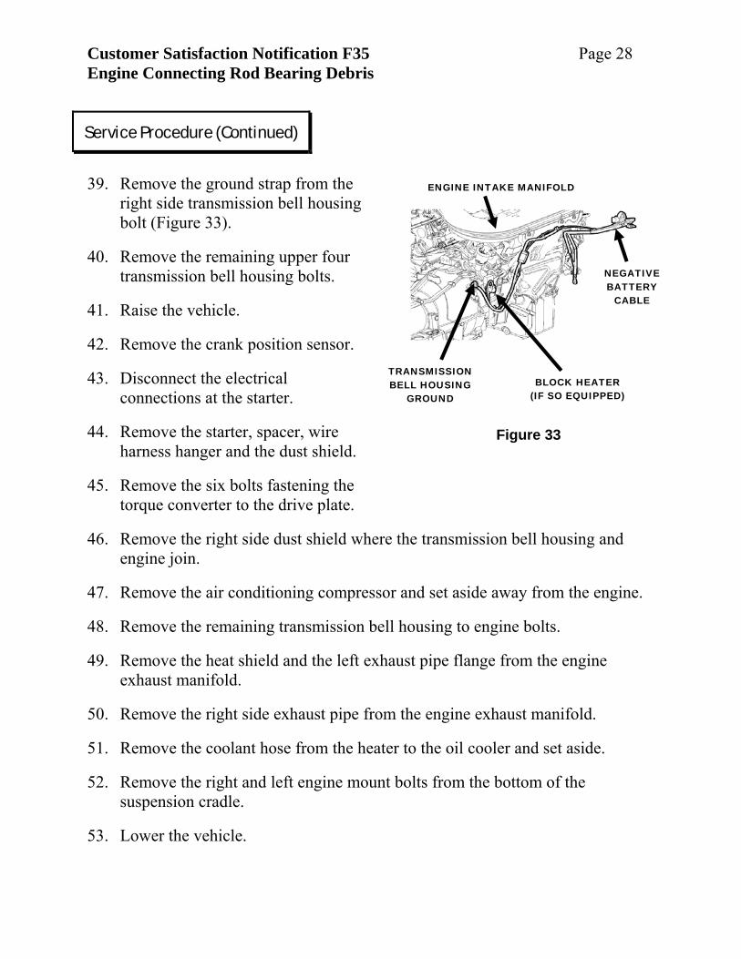
39. Remove the ground strap from the
right side transmission bell housing bolt (Figure 33).
40. Remove the remaining upper four transmission bell housing bolts.
41. Raise the vehicle.
42. Remove the crank position sensor.
43. Disconnect the electrical connections at the starter.
44. Remove the starter, spacer, wire harness hanger and the dust shield.
45. Remove the six bolts fastening the torque converter to the drive plate.
46. Remove the right side dust shield where the transmission bell housing and engine join.
47. Remove the air conditioning compressor and set aside away from the engine.
48. Remove the remaining transmission bell housing to engine bolts.
49. Remove the heat shield and the left exhaust pipe flange from the engine exhaust manifold.
50. Remove the right side exhaust pipe from the engine exhaust manifold.
51. Remove the coolant hose from the heater to the oil cooler and set aside.
52. Remove the right and left engine mount bolts from the bottom of the suspension cradle.
53. Lower the vehicle.
Service Procedure (Continued)
Customer Satisfaction Notification F35 Page 29 Engine Connecting Rod Bearing Debris
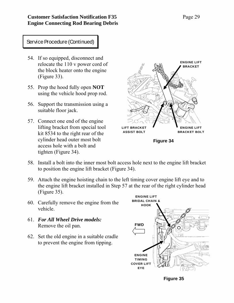
Figure 34
ENGINE LIFT BRACKET
LIFT BRACKET ASSIST BOLT
ENGINE LIFT BRACKET BOLT
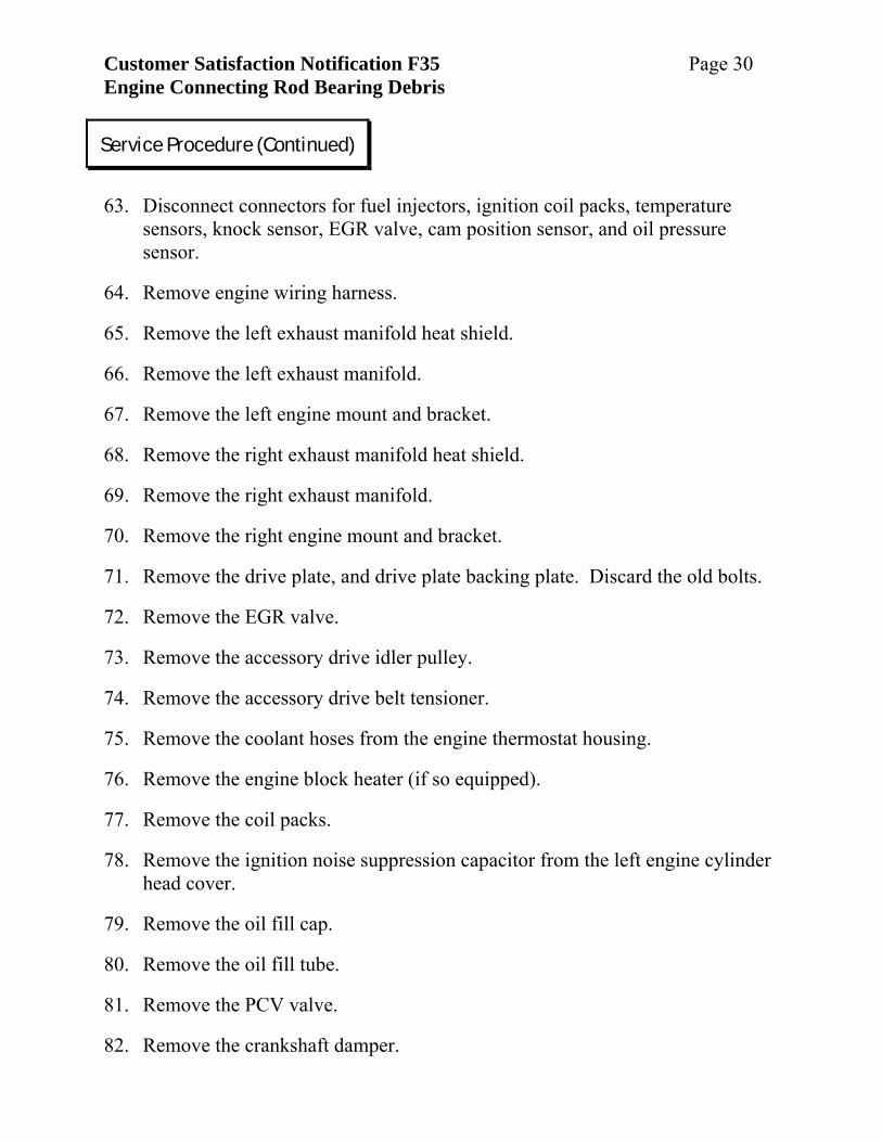
Figure 35
ENGINE TIMING
COVER LIFT EYE
ENGINE LIFT BRIDAL CHAIN &
HOOK
FWD
54. If so equipped, disconnect and
relocate the 110 v power cord of the block heater onto the engine (Figure 33).
55. Prop the hood fully open NOT using the vehicle hood prop rod.
56. Support the transmission using a suitable floor jack.
57. Connect one end of the engine lifting bracket from special tool kit 8534 to the right rear of the cylinder head outer most bolt access hole with a bolt and tighten (Figure 34).
58. Install a bolt into the inner most bolt access hole next to the engine lift bracket to position the engine lift bracket (Figure 34).
59. Attach the engine hoisting chain to the left timing cover engine lift eye and to the engine lift bracket installed in Step 57 at the rear of the right cylinder head (Figure 35).
60. Carefully remove the engine from the vehicle.
61. For All Wheel Drive models: Remove the oil pan.
62. Set the old engine in a suitable cradle to prevent the engine from tipping.
Service Procedure (Continued)
Customer Satisfaction Notification F35 Page 30 Engine Connecting Rod Bearing Debris
63. Disconnect connectors for fuel injectors, ignition coil packs, temperature
sensors, knock sensor, EGR valve, cam position sensor, and oil pressure sensor.
64. Remove engine wiring harness.
65. Remove the left exhaust manifold heat shield.
66. Remove the left exhaust manifold.
67. Remove the left engine mount and bracket.
68. Remove the right exhaust manifold heat shield.
69. Remove the right exhaust manifold.
70. Remove the right engine mount and bracket.
71. Remove the drive plate, and drive plate backing plate. Discard the old bolts.
72. Remove the EGR valve.
73. Remove the accessory drive idler pulley.
74. Remove the accessory drive belt tensioner.
75. Remove the coolant hoses from the engine thermostat housing.
76. Remove the engine block heater (if so equipped).
77. Remove the coil packs.
78. Remove the ignition noise suppression capacitor from the left engine cylinder head cover.
79. Remove the oil fill cap.
80. Remove the oil fill tube.
81. Remove the PCV valve.
82. Remove the crankshaft damper.
Service Procedure (Continued)
Customer Satisfaction Notification F35 Page 31 Engine Connecting Rod Bearing Debris
83. Remove the block heater – if so equipped.
84. Remove engine lifting chains and brackets.
85. Install the block heater onto the new engine and tighten the bolt to 17 in. lbs. (2 N·m) – if so equipped.
86. Install crankshaft damper and tighten the damper bolt to 70 ft. lbs. (95 N·m).
87. Install the PCV valve onto the new engine.
88. Install the oil fill tube onto the new engine and tighten.
89. Install ignition noise suppression capacitor to the left engine cylinder head cover and tighten fastener.
90. Install the coil packs and tighten the fasteners to 60 in. lbs. (6.7 N·m).
91. Install coolant hose to the thermostat housing.
92. Install the block heater (if so equipped) and lay the 110 v power cord on top of the engine.
93. Install accessory drive belt tensioner and tighten the bolt to 40 ft. lbs. (54 N·m).
94. Install accessory drive idler pulley and tighten the bolt to 250 in. lbs. (28 N·m).
95. Remove the plug in the EGR passage at the rear of the right cylinder head.
96. Install the EGR valve to the cylinder head using a new gasket. Tighten the fasteners to 97 in. lbs. (11 N·m).
97. Remove the old thread locking compound from the threaded holes at the end of the crankshaft where the drive plate mounts.
98. Install the drive plate and drive plate backing plates using new bolts. Tighten the bolts to 55 ft. lbs. (75 N·m).
99. Apply a thin coat of universal suspension grease into the end of the crankshaft pilot hole for the torque converter.
Service Procedure (Continued)
Customer Satisfaction Notification F35 Page 32 Engine Connecting Rod Bearing Debris
100. Install the right engine mount and bracket. Tighten the bolts to
55 ft. lbs. (75 N·m).
101. Install the right exhaust manifold using a new gasket. Tighten the bolts to 200 in. lbs. (23 N·m).
CAUTION: Do not over tighten.
102. Install the right exhaust manifold heat shield and tighten the bolts to 105 in. lbs. (12 N·m).
103. Install the left engine mount and bracket. Tighten the bolts to 55 ft. lbs. (75 N·m).
104. Install the left exhaust manifold using a new gasket. Tighten the bolts to 200 in. lbs. (23 N·m).
CAUTION: Do not over tighten.
105. Install the left exhaust manifold heat shield and tighten the fasteners.
106. Install the engine wire harness.
107. Connect to the engine wire harness the fuel injectors, ignition coil packs, temperature sensors, knock sensor, EGR valve, cam position sensor, and oil pressure sensor.
108. Connect one end of the engine lifting bracket from special tool kit 8534 to the right rear of the cylinder head outer most bolt access hole with a bolt and tighten (Figure 34).
109. Install a bolt into the inner most bolt access hole next to the engine lift bracket to position the engine lift bracket (Figure 34).
110. Attach the engine hoisting chain to the left timing cover engine lift eye and to the engine lift bracket installed in Step 108 at the rear of the right cylinder head (Figure 35).
Service Procedure (Continued)
Customer Satisfaction Notification F35 Page 33 Engine Connecting Rod Bearing Debris
Figure 36
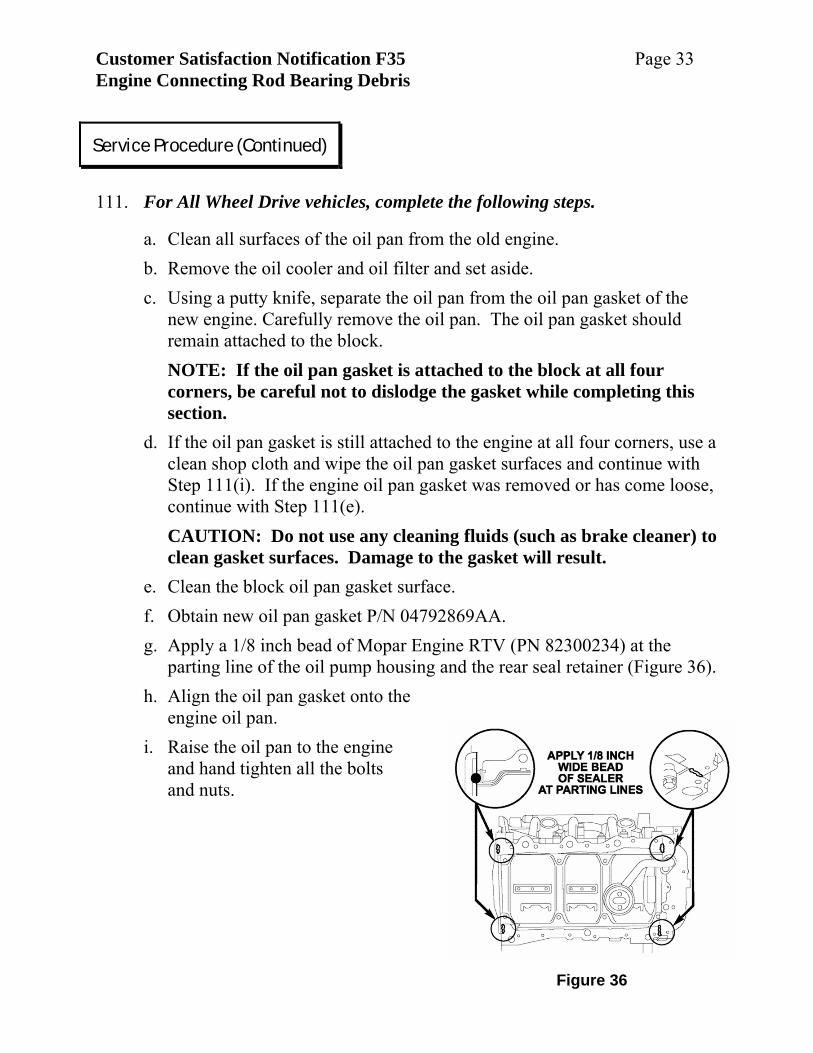
111. For All Wheel Drive vehicles, complete the following steps.
a. Clean all surfaces of the oil pan from the old engine. b. Remove the oil cooler and oil filter and set aside. c. Using a putty knife, separate the oil pan from the oil pan gasket of the
new engine. Carefully remove the oil pan. The oil pan gasket should remain attached to the block.
NOTE: If the oil pan gasket is attached to the block at all four corners, be careful not to dislodge the gasket while completing this section.
d. If the oil pan gasket is still attached to the engine at all four corners, use a clean shop cloth and wipe the oil pan gasket surfaces and continue with Step 111(i). If the engine oil pan gasket was removed or has come loose, continue with Step 111(e).
CAUTION: Do not use any cleaning fluids (such as brake cleaner) to clean gasket surfaces. Damage to the gasket will result.
e. Clean the block oil pan gasket surface. f. Obtain new oil pan gasket P/N 04792869AA. g. Apply a 1/8 inch bead of Mopar Engine RTV (PN 82300234) at the
parting line of the oil pump housing and the rear seal retainer (Figure 36). h. Align the oil pan gasket onto the
engine oil pan. i. Raise the oil pan to the engine
and hand tighten all the bolts and nuts.
Service Procedure (Continued)
Customer Satisfaction Notification F35 Page 34 Engine Connecting Rod Bearing Debris
j. Align the rear face of the engine oil pan with the rear face of the engine.
The plane of the back of the engine oil pan must be on the same plane as the back of the engine. Use a suitable straight edge to check if the rear oil pan face and the rear block face of the block are properly aligned.
k. Starting at the center of the oil pan and working towards the ends, tighten the 8 mm oil pan bolts and nuts to 20 ft. lbs. (28 N·m).
l. Check the alignment of the rear face of the oil pan with the rear face of the engine with a straight edge. If they are out of alignment, repeat Steps 111(j) and 111(k).
CAUTION: Steps 111(j) through 111 (l) must be followed to avoid damage to the oil pan.
m. Tighten the two 6 mm engine oil pan bolt located at the rear of the oil pan to 105 in. lbs (12 N·m).
n. Wipe clean both the upper engine oil cooler sealing “O” ring and the oil filter mounting surface.
o. Position oil cooler to fitting on oil pan. The notch in the engine oil pan oil cooler pad must fit into the cut-out of the oil cooler.
p. While holding the engine oil cooler in position, install the oil cooler/filter nipple and tighten to 45 ft. lbs. (61 N·m).
NOTE: Do not over tighten. Damage to the oil cooler will occur. 112. Install a new oil filter and tighten to 106 in. lbs. (12 N·m).
113. Carefully install the engine into the vehicle. Make sure the engine to transmission dowels align with the transmission bell housing.
114. Install the two upper engine-to-transmission bell housing bolts and snug the bolts.
115. Remove the floor jack supporting the transmission.
116. Remove the engine lifting chains and bracket.
117. Remove the prop holding the hood fully open and use the vehicle hood prop.
Service Procedure (Continued)
Customer Satisfaction Notification F35 Page 35 Engine Connecting Rod Bearing Debris
118. Install the connector 110 v power cord to the to the block heater.
119. Raise the vehicle.
120. Install the right and left engine mount nuts on the studs securing the engine mounts to the suspension cradle. Tighten the nuts to 55 ft. lbs. (75 N·m).
121. Install two lower 10 mm engine oil pan to transmission bell housing bolts nearest to the drive plate bolt access and tighten to 55 ft. lbs. (75 N·m) (Figure 16).
122. Install the hose to the oil cooler from the heater.
123. Install the right side exhaust pipe to the engine exhaust manifold and tighten the bolts to 25 ft. lbs. (34 N·m).
124. Install the left side exhaust pipe and heat shield to the engine exhaust manifold and tighten the bolts to 25 ft. lbs. (34 N·m).
125. Install the right dust shield and tighten bolts to 95 in. lbs. (10 N·m).
126. Install the remaining 10 mm engine to transmission bell housing bolts (except the right and left bolts flanking the two center bolts installed in Step 114) and tighten to 40 ft. lbs. (55 N·m).
127. Install the air conditioning compressor. Fasten the bracket holding the transmission oil cooler lines onto compressor with the rear most bolt. Tighten the bolts to 19 ft. lbs. (26 N·m).
128. Align the torque converter to the drive plate and install the bolts. Tighten the bolts to 55 ft. lbs. (75 N·m).
Service Procedure (Continued)
Customer Satisfaction Notification F35 Page 36 Engine Connecting Rod Bearing Debris
Figure 38
SPACER
STARTER
DUST SHIELD
HARNESS HANGER
FWD
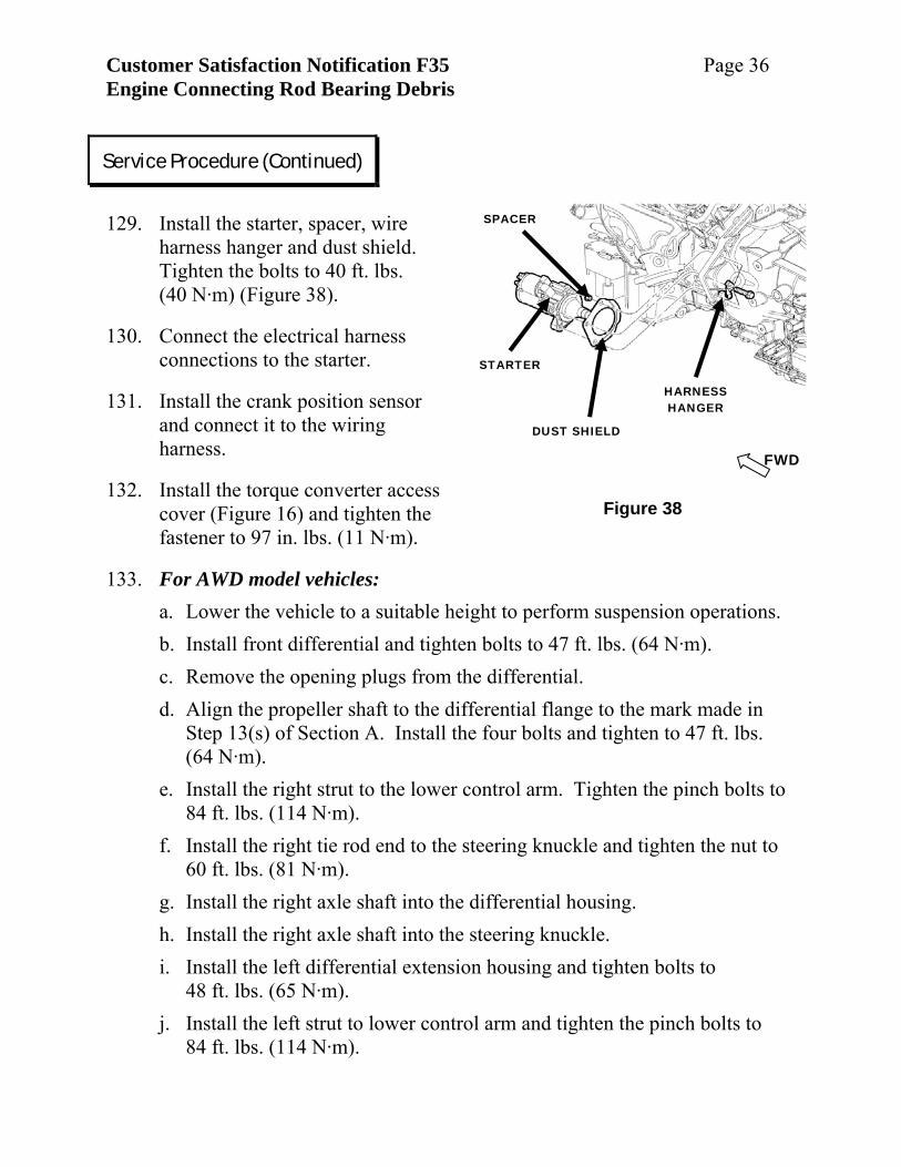
129. Install the starter, spacer, wire
harness hanger and dust shield. Tighten the bolts to 40 ft. lbs. (40 N·m) (Figure 38).
130. Connect the electrical harness connections to the starter.
131. Install the crank position sensor and connect it to the wiring harness.
132. Install the torque converter access cover (Figure 16) and tighten the fastener to 97 in. lbs. (11 N·m).
133. For AWD model vehicles: a. Lower the vehicle to a suitable height to perform suspension operations. b. Install front differential and tighten bolts to 47 ft. lbs. (64 N·m). c. Remove the opening plugs from the differential. d. Align the propeller shaft to the differential flange to the mark made in
Step 13(s) of Section A. Install the four bolts and tighten to 47 ft. lbs. (64 N·m).
e. Install the right strut to the lower control arm. Tighten the pinch bolts to 84 ft. lbs. (114 N·m).
f. Install the right tie rod end to the steering knuckle and tighten the nut to 60 ft. lbs. (81 N·m).
g. Install the right axle shaft into the differential housing. h. Install the right axle shaft into the steering knuckle. i. Install the left differential extension housing and tighten bolts to
48 ft. lbs. (65 N·m). j. Install the left strut to lower control arm and tighten the pinch bolts to
84 ft. lbs. (114 N·m).
Service Procedure (Continued)
Customer Satisfaction Notification F35 Page 37 Engine Connecting Rod Bearing Debris
k. Install the left tie-rod end to the steering knuckle and tighten the nut to
60 ft. lbs. (81 N·m). l. Install left axle shaft into the differential extension housing. m. Install left axle shaft into the steering knuckle. n. Install left and right sway bar link bolts to the strut clevis brackets and
tighten bolts to 95 ft. lbs. (128 N·m). o. Install right and left hub nuts to right and left axles and tighten to 157 ft.
lbs. (213 N·m). p. Install right and left brake pads and calipers. Tighten caliper bolts to
44 ft. lbs. (60 N·m). q. Install right and left upper control arm ball joint to steering knuckle.
Tighten the bolt to 35 ft. lbs. (47 N·m) + 90◦. r. Install right and left vehicle speed sensors to the steering knuckle.
Tighten bolts to 96 in. lbs. (11 N·m). s. Install right and left front wheel and tire assembly and tighten the lug
nuts to 110 ft. lbs. (149 N·m). t. Check the front differential for proper differential oil level. Adjust as
needed. Continue with Step 133.
134. For RWD models: a. Install the steering rack to the sub-frame and tighten the bolts to 75 ft.
lbs. (102 N.m). b. Align the steering coupler to the steering gear using the mark made in
Step 16(a) of Section A. c. Install the steering coupler bolt and tighten to 40 ft. lbs. (54 N·m).
135. Install the lower plastic splash shield under the engine.
136. Lower the vehicle.
137. Install the left engine-to-transmission bell housing bolt next to the two center engine to transmission bell housing bolts. Tighten the left and the two center bolts to 55 ft. lbs. (75 N·m).
Service Procedure (Continued)
Customer Satisfaction Notification F35 Page 38 Engine Connecting Rod Bearing Debris
138. Install the engine-to-chassis ground to the remaining right engine-to-
transmission bolt. Tighten the bolt to 55 ft. lbs. (75 N·m).
139. Attach the engine wire harness/support bracket to the top of the transmission bell housing.
140. Connect the heater hose at the rear of the engine.
141. Connect the coolant recovery bottle hose.
142. Remove the caps from the air conditioning lines and compressor.
143. Connect both the high and low pressure lines to the air conditioning compressor.
144. Install the lower radiator hose.
145. Install the power steering pump and tighten the bolts to 21 ft. lbs. (28 N·m).
146. Install the serpentine belt.
147. Install the upper radiator hose.
148. Connect the engine harness to the chassis harness.
149. Connect the right side oxygen sensor.
150. Connect the left side ground strap to the left valve cover and to the cylinder head.
151. Connect the right oxygen sensor.
152. Connect chassis fuel line to the engine fuel rail.
153. Install generator and support bracket. Tighten the bottom bolts to 48 ft. lbs. (65 N·m). Leave the upper bolt with the support bracket loose at this time.
154. Connect the electrical harness to the generator.
155. Install engine silencer pad onto the engine.
Service Procedure (Continued)
Customer Satisfaction Notification F35 Page 39 Engine Connecting Rod Bearing Debris
Figure 39
EGR VALVE EGR TUBE
UPPER INTAKE MANIFOLD
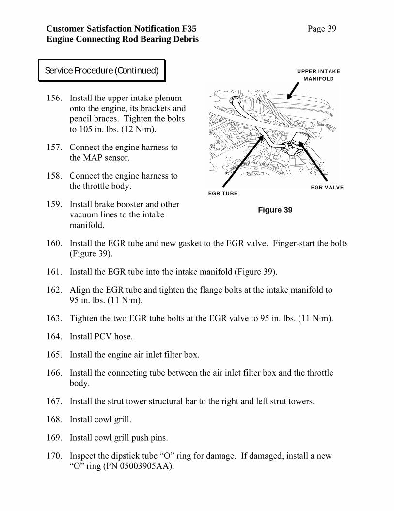
156. Install the upper intake plenum
onto the engine, its brackets and pencil braces. Tighten the bolts to 105 in. lbs. (12 N·m).
157. Connect the engine harness to the MAP sensor.
158. Connect the engine harness to the throttle body.
159. Install brake booster and other vacuum lines to the intake manifold.
160. Install the EGR tube and new gasket to the EGR valve. Finger-start the bolts (Figure 39).
161. Install the EGR tube into the intake manifold (Figure 39).
162. Align the EGR tube and tighten the flange bolts at the intake manifold to 95 in. lbs. (11 N·m).
163. Tighten the two EGR tube bolts at the EGR valve to 95 in. lbs. (11 N·m).
164. Install PCV hose.
165. Install the engine air inlet filter box.
166. Install the connecting tube between the air inlet filter box and the throttle body.
167. Install the strut tower structural bar to the right and left strut towers.
168. Install cowl grill.
169. Install cowl grill push pins.
170. Inspect the dipstick tube “O” ring for damage. If damaged, install a new “O” ring (PN 05003905AA).
Service Procedure (Continued)
Customer Satisfaction Notification F35 Page 40 Engine Connecting Rod Bearing Debris
171. Install the dipstick tube into the oil pan.
172. Install the dipstick tube mounting bolt and tighten to 30 ft. lbs. (41N.m).
173. Install the generator upper support bracket to the generator. Tighten the generator bolt to 48 ft. lbs. (65 N·m) and the engine block bolt to 40 ft. lbs. (54 N·m).
174. Install the engine dipstick.
175. Install six new quarts of 10W30 engine oil.
176. Install coolant into the cooling system.
177. Install radiator cap.
178. Connect the battery.
179. Verify the seating of the cargo floor panel.
180. Start the vehicle and inspect for leaks.
181. Evacuate and charge the air conditioning system.
182. Return vehicle to the customer. D. CS (AWD and FWD) Engine Replacement 1. Install the #2 connecting rod cap and finger start the connecting rod bolts.
2. Install the engine oil pan with four bolts and snug tight.
3. Lower the vehicle.
4. Remove engine trim cover.
5. Disconnect the chassis fuel line from the engine fuel rail.
6. Cap both open fuel lines.
Service Procedure (Continued)
Customer Satisfaction Notification F35 Page 41 Engine Connecting Rod Bearing Debris
Figure 40
AIR CLEANER BOX
ENGINE COVER
7. Drain the engine coolant from the vehicle and save for reuse.
8. Disconnect the cruise control cable from the throttle body.
9. Remove the cruise control solenoid and vacuum reservoir.
10. Remove radiator shroud.
11. Remove radiator core support.
12. Remove radiator cooling fans.
13. Remove upper radiator hose.
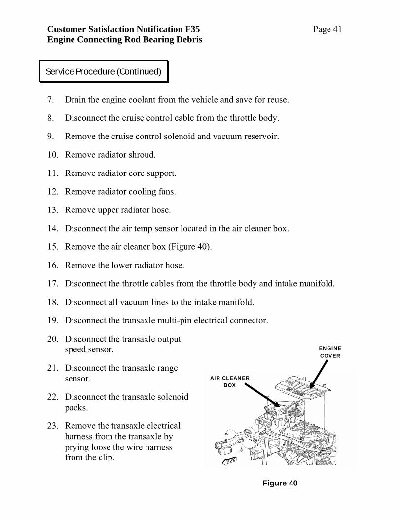
14. Disconnect the air temp sensor located in the air cleaner box.
15. Remove the air cleaner box (Figure 40).
16. Remove the lower radiator hose.
17. Disconnect the throttle cables from the throttle body and intake manifold.
18. Disconnect all vacuum lines to the intake manifold.
19. Disconnect the transaxle multi-pin electrical connector.
20. Disconnect the transaxle output speed sensor.
21. Disconnect the transaxle range sensor.
22. Disconnect the transaxle solenoid packs.
23. Remove the transaxle electrical harness from the transaxle by prying loose the wire harness from the clip.
Service Procedure (Continued)
Customer Satisfaction Notification F35 Page 42 Engine Connecting Rod Bearing Debris
24. Discharge the air conditioning system using a suitable refrigerant recovery
system.
25. Remove the engine wire harness ground at left inner frame rail.
26. Disconnect the transaxle selector shift cable.
27. Disconnect the transaxle oil cooler lines at the radiator.
28. Disconnect the block heater (if so equipped) 110 v power cord at the heater.
29. Disconnect the hose to the coolant recovery bottle.
30. Disconnect all heater hoses at the heater.
31. Disconnect the front brake lines. Use a brake pedal prop to prevent draining of the brake fluid from the brake reservoir.
32. Disconnect both air conditioning lines at the compressor and cap off the openings.
33. Disconnect the air conditioning clutch electrical connector.
34. Disconnect the electrical harness from the generator.
35. Disconnect the electrical harness from the duty cycle purge solenoid.
36. Disconnect the electrical harness from the starter.
37. Disconnect the engine harness from the chassis harness.
38. Disconnect the front oxygen sensor.
39. Raise the vehicle.
40. Remove both front wheel/tire assemblies.
41. Unfasten the front half of both right and left inner fender liners and roll the liners rearward.
42. Disconnect the harness from the PCM.
Service Procedure (Continued)
Customer Satisfaction Notification F35 Page 43 Engine Connecting Rod Bearing Debris
Figure 41
HUB NUT
STEERING KNUCKLE
SWAY BAR LINK
PINCH BOLTS
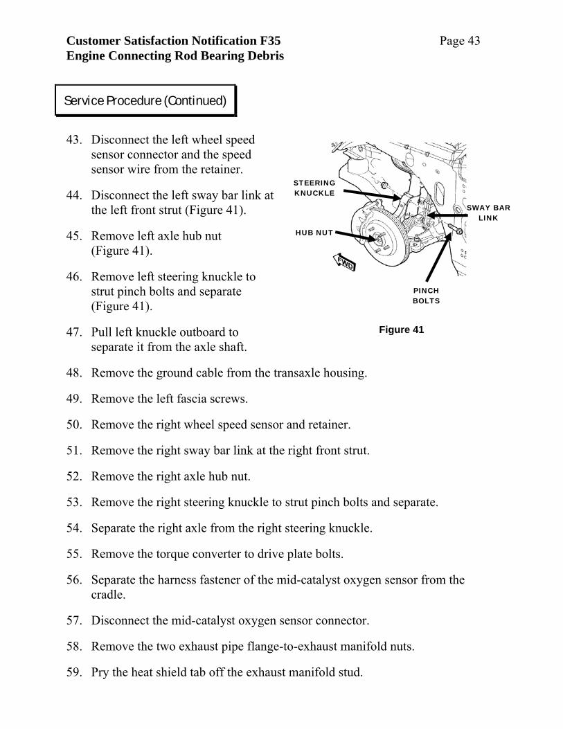
43. Disconnect the left wheel speed
sensor connector and the speed sensor wire from the retainer.
44. Disconnect the left sway bar link at the left front strut (Figure 41).
45. Remove left axle hub nut (Figure 41).
46. Remove left steering knuckle to strut pinch bolts and separate (Figure 41).
47. Pull left knuckle outboard to separate it from the axle shaft.
48. Remove the ground cable from the transaxle housing.
49. Remove the left fascia screws.
50. Remove the right wheel speed sensor and retainer.
51. Remove the right sway bar link at the right front strut.
52. Remove the right axle hub nut.
53. Remove the right steering knuckle to strut pinch bolts and separate.
54. Separate the right axle from the right steering knuckle.
55. Remove the torque converter to drive plate bolts.
56. Separate the harness fastener of the mid-catalyst oxygen sensor from the cradle.
57. Disconnect the mid-catalyst oxygen sensor connector.
58. Remove the two exhaust pipe flange-to-exhaust manifold nuts.
59. Pry the heat shield tab off the exhaust manifold stud.
Service Procedure (Continued)
Customer Satisfaction Notification F35 Page 44 Engine Connecting Rod Bearing Debris
60. Separate the exhaust pipe from the engine and support the exhaust system.
61. Remove the vehicle center exhaust system hanger bolts.
62. Remove the vehicle rear exhaust system hanger bolts.
63. Remove the exhaust system from the vehicle.
64. Separate the brake lines from the brake line spacer isolator located on the left side of the engine compartment by the brake hydraulic control unit.
65. For AWD model: a. Paint mark the propeller shaft to the rear differential at the PTU. b. Separate the propeller shaft to the rear differential at the transaxle power
transfer unit. Support the propeller shaft to the under body. c. Remove engine/transaxle assembly support plate from the suspension
cradle.
66. Remove steering coupling pin using tool # 6831A.
67. Remove both engine mount-to-suspension cradle nuts.
68. Paint mark the suspension cradle to the chassis.
69. Disconnect the crank position sensor.
70. Position the front (right and left) brake lines aside to clear the suspension cradle when it is dropped.
71. Place suspension cradle support fixture (essential tool #8874) under the vehicle.
72. Lower the vehicle onto the suspension cradle support fixture.
73. Remove right engine support mount.
74. Remove all four suspension cradle-to-body bolts.
75. Raise the vehicle and slide the suspension cradle fixture out from under the vehicle.
Service Procedure (Continued)
Customer Satisfaction Notification F35 Page 45 Engine Connecting Rod Bearing Debris
NOTE: The following steps will be performed with the engine and transaxle on the suspension cradle.
76. Remove the left axle shaft.
77. Remove the serpentine drive belt.
78. Remove the generator.
79. Remove the power steering reservoir.
80. Remove the power steering pump.
81. Remove the belt tensioner.
82. Remove the three idler pulleys.
83. Disconnect the IAC connector at the throttle body.
84. Disconnect the TPS connector at the throttle body.
85. Disconnect the intake manifold short runner actuation valve connector.
86. Disconnect the intake manifold long runner actuation valve connector.
87. Disconnect the MAP sensor located on the intake manifold.
88. Unfasten the wiring harness support bracket.
89. Remove the PVC hose.
90. Remove the PVC valve.
91. Remove crankshaft damper.
92. Remove EGR tube.
93. Remove oil fill tube.
94. Remove the two intake manifold support brackets.
95. Remove the intake manifold from the engine.
Service Procedure (Continued)
Customer Satisfaction Notification F35 Page 46 Engine Connecting Rod Bearing Debris
96. Disconnect the remaining components from the engine wire harness (knock
sensor, fuel injectors, ignition coils, ignition noise suppression capacitors, EGR valve, cam position sensor, oil pressure sending unit, etc).
97. Remove the engine wire harness.
98. Remove right rear exhaust heat shield.
99. Remove exhaust cross over pipe.
100. Remove the front exhaust manifold and discard the exhaust manifold to engine gasket.
101. Remove the rear exhaust manifold and discard the exhaust manifold to engine gasket.
102. Remove the EGR valve and discard the EGR valve-to-cylinder head gasket.
103. Remove the ignition coil packs.
104. Remove the coolant hoses from the engine (oil cooler-to-engine, oil cooler-to-heater).
105. Remove the valve cover ground straps.
106. Remove the transaxle rear structural support bolt from the engine.
107. Remove the starter from the engine.
108. Remove the crankshaft position sensor.
109. Remove the air conditioning compressor.
110. Remove the air conditioning compressor mounting bracket.
Service Procedure (Continued)
Customer Satisfaction Notification F35 Page 47 Engine Connecting Rod Bearing Debris
Figure 42
LEFT BRACKET
HEAT SHIELD
PTU
RIGHT BRACKET
BRACE
PTU COLLAR
ENGINE
TRANSAXLE
FWD
Figure 43
ENGINE LIFT BRACKET
LIFT BRACKET ASSIST BOLT
ENGINE LIFT BRACKET BOLT
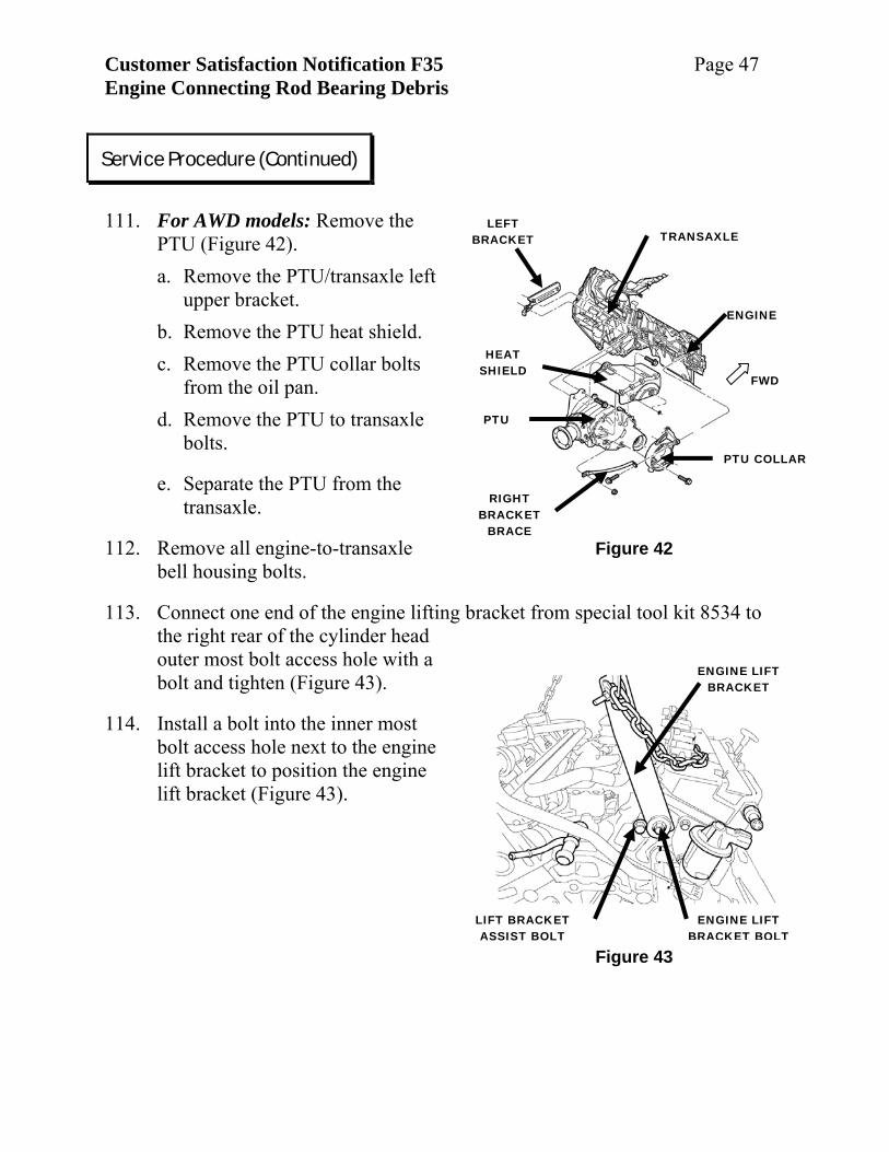
111. For AWD models: Remove the
PTU (Figure 42). a. Remove the PTU/transaxle left
upper bracket. b. Remove the PTU heat shield. c. Remove the PTU collar bolts
from the oil pan. d. Remove the PTU to transaxle
bolts.
e. Separate the PTU from the transaxle.
112. Remove all engine-to-transaxle bell housing bolts.
113. Connect one end of the engine lifting bracket from special tool kit 8534 to the right rear of the cylinder head outer most bolt access hole with a bolt and tighten (Figure 43).
114. Install a bolt into the inner most bolt access hole next to the engine lift bracket to position the engine lift bracket (Figure 43).
Service Procedure (Continued)
Customer Satisfaction Notification F35 Page 48 Engine Connecting Rod Bearing Debris
Figure 44
ENGINE TIMING
COVER LIFT EYE
ENGINE LIFT BRIDAL CHAIN &
HOOK
FWD
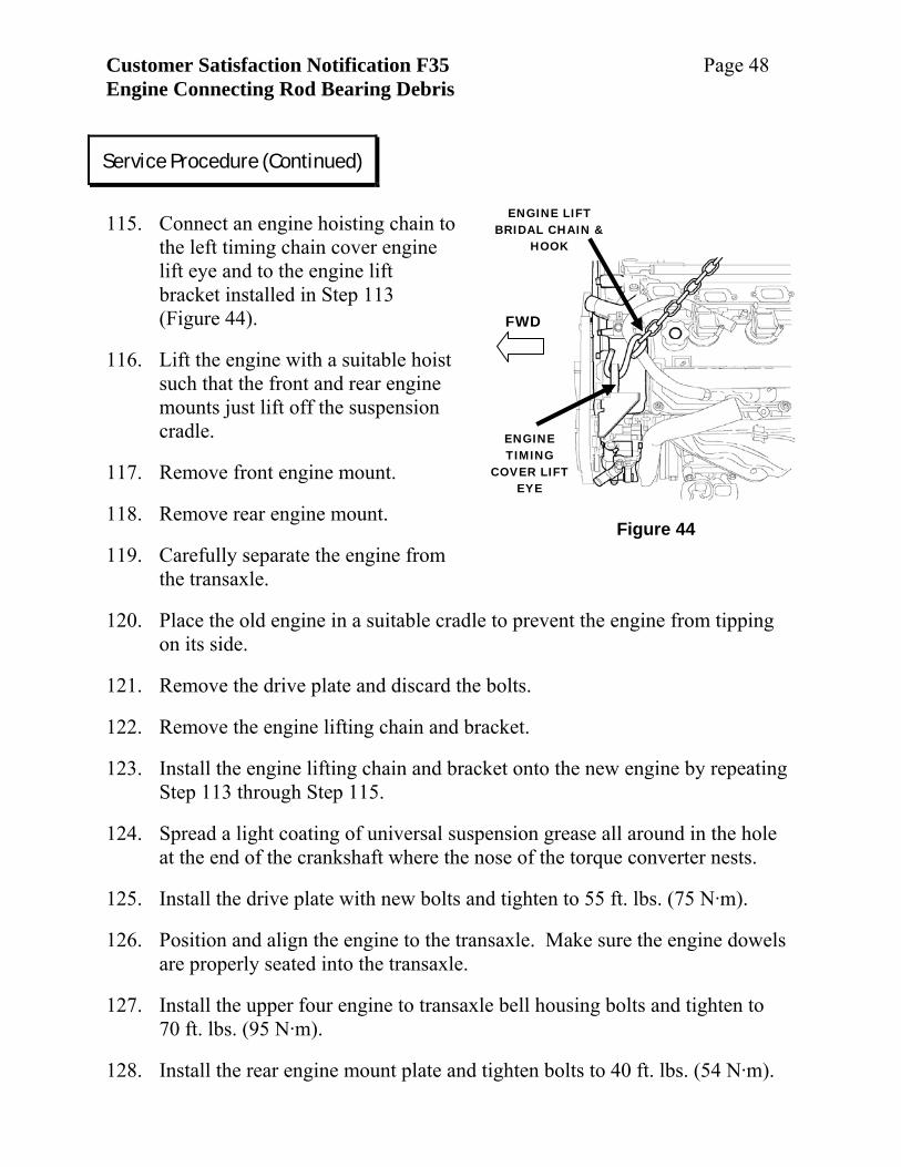
115. Connect an engine hoisting chain to
the left timing chain cover engine lift eye and to the engine lift bracket installed in Step 113 (Figure 44).
116. Lift the engine with a suitable hoist such that the front and rear engine mounts just lift off the suspension cradle.
117. Remove front engine mount.
118. Remove rear engine mount.
119. Carefully separate the engine from the transaxle.
120. Place the old engine in a suitable cradle to prevent the engine from tipping on its side.
121. Remove the drive plate and discard the bolts.
122. Remove the engine lifting chain and bracket.
123. Install the engine lifting chain and bracket onto the new engine by repeating Step 113 through Step 115.
124. Spread a light coating of universal suspension grease all around in the hole at the end of the crankshaft where the nose of the torque converter nests.
125. Install the drive plate with new bolts and tighten to 55 ft. lbs. (75 N·m).
126. Position and align the engine to the transaxle. Make sure the engine dowels are properly seated into the transaxle.
127. Install the upper four engine to transaxle bell housing bolts and tighten to 70 ft. lbs. (95 N·m).
128. Install the rear engine mount plate and tighten bolts to 40 ft. lbs. (54 N·m).
Service Procedure (Continued)
Customer Satisfaction Notification F35 Page 49 Engine Connecting Rod Bearing Debris
129. Install the rear engine mount upper nut and tighten to 75 ft. lbs. (101 N·m).
130. Install the rear engine mount bracket bolts and tighten to 40 ft. lbs. (54 N·m).
131. Install the rear engine mount to the engine mount bracket and tighten to 75 ft. lbs. (101 N·m).
132. Install the left motor mount to the engine block and tighten the bolts to 40 ft. lbs. (54 N·m).
133. Lower the engine into the suspension cradle and remove the engine lifting chain and bracket.
134. Install the remaining engine-to-transaxle bell housing bolts and tighten to 70 ft. lbs. (95 N·m).
135. For AWD models: Install PTU unit (Figure 42) as follows:
a. Align the PTU into the transaxle, install the upper bolts and tighten to 40 ft. lbs. (54 N·m).
b. Install the PTU to transaxle lower bolts and tighten to 21 ft. lbs. (28 N·m).
c. Install the PTU collar and brace bolts to the oil pan and tighten to 40 ft. lbs. (54 N·m).
d. Install the PTU heat shield and tighten bolts to 20 ft. lbs. (28 N·m). e. Install the PTU/transaxle left bracket and tighten the bolts to
40 ft. lbs. (54 N·m).
Service Procedure (Continued)
Customer Satisfaction Notification F35 Page 50 Engine Connecting Rod Bearing Debris
TIGHTEN FIRST
TIGHTEN SECOND
TIGHTEN LAST
A C COMPRESSOR
BRACKET
TIGHTEN THIRD
Figure 45
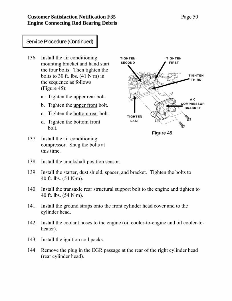
136. Install the air conditioning
mounting bracket and hand start the four bolts. Then tighten the bolts to 30 ft. lbs. (41 N·m) in the sequence as follows (Figure 45): a. Tighten the upper rear bolt. b. Tighten the upper front bolt. c. Tighten the bottom rear bolt. d. Tighten the bottom front
bolt.
137. Install the air conditioning compressor. Snug the bolts at this time.
138. Install the crankshaft position sensor.
139. Install the starter, dust shield, spacer, and bracket. Tighten the bolts to 40 ft. lbs. (54 N·m).
140. Install the transaxle rear structural support bolt to the engine and tighten to 40 ft. lbs. (54 N·m).
141. Install the ground straps onto the front cylinder head cover and to the cylinder head.
142. Install the coolant hoses to the engine (oil cooler-to-engine and oil cooler-to-heater).
143. Install the ignition coil packs.
144. Remove the plug in the EGR passage at the rear of the right cylinder head (rear cylinder head).
Service Procedure (Continued)
Customer Satisfaction Notification F35 Page 51 Engine Connecting Rod Bearing Debris
Figure 46 EGR VALVE
EGR TUBE
RT CYLINDER HEAD COVER
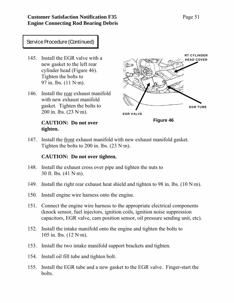
145. Install the EGR valve with a
new gasket to the left rear cylinder head (Figure 46). Tighten the bolts to 97 in. lbs. (11 N·m).
146. Install the rear exhaust manifold with new exhaust manifold gasket. Tighten the bolts to 200 in. lbs. (23 N·m).
CAUTION: Do not over tighten.
147. Install the front exhaust manifold with new exhaust manifold gasket. Tighten the bolts to 200 in. lbs. (23 N·m).
CAUTION: Do not over tighten.
148. Install the exhaust cross over pipe and tighten the nuts to 30 ft. lbs. (41 N·m).
149. Install the right rear exhaust heat shield and tighten to 98 in. lbs. (10 N·m).
150. Install engine wire harness onto the engine.
151. Connect the engine wire harness to the appropriate electrical components (knock sensor, fuel injectors, ignition coils, ignition noise suppression capacitors, EGR valve, cam position sensor, oil pressure sending unit, etc).
152. Install the intake manifold onto the engine and tighten the bolts to 105 in. lbs. (12 N·m).
153. Install the two intake manifold support brackets and tighten.
154. Install oil fill tube and tighten bolt.
155. Install the EGR tube and a new gasket to the EGR valve. Finger-start the bolts.
Service Procedure (Continued)
Customer Satisfaction Notification F35 Page 52 Engine Connecting Rod Bearing Debris
156. Install the EGR tube into the intake manifold and tighten bolts to
95 in. lbs. (11 N·m).
157. Tighten the two EGR tube bolts at the EGR valve to 95 in. lbs. (11 N·m).
158. Tighten the EGR tube bracket bolt to 30 ft. lbs. (41 N·m).
159. Install the PVC valve into the valve cover.
160. Install the crankshaft damper and tighten the bolt to 70 ft. lbs. (95 N·m).
161. Install the PCV hose.
162. Attach the engine wire harness to the harness support bracket.
163. Connect the harness to the MAP sensor.
164. Connect the harness to the intake manifold short runner actuation valve.
165. Connect the harness to the intake manifold long runner actuation valve.
166. Connect the harness to the TPS on the throttle body.
167. Connect the harness to the IAC on the throttle body.
168. Install the three accessory drive idler pulleys onto the engine and tighten the bolts to 250 in. lbs. (28 N·m).
169. Install the accessory drive tensioner and tighten the bolt to 40 ft. lbs. (54 N·m).
170. Install the power steering pump and tighten the bolts to 21 ft. lbs. (28 N·m).
171. Install the power steering pump reservoir and tighten the bolts to 200 in. lbs. (23 N·m).
172. Install the generator and bracket. Tighten the lower two generator bolts to 40 ft. lbs. (54 N·m). Leave the bracket bolts finger tight.
173. Install the serpentine belt.
Service Procedure (Continued)
Customer Satisfaction Notification F35 Page 53 Engine Connecting Rod Bearing Debris
174. Install the right axle shaft into the transaxle (or PTU).
175. Position the suspension cradle fixture underneath the vehicle.
176. Lower the vehicle onto the suspension cradle.
177. Align the suspension cradle with the paint marks made in Step 68.
178. Install the four suspension cradle bolts and tighten to 120 ft. lbs. (163 N·m).
179. Install right (upper) engine mount. Tighten the timing cover bolts to 40 ft. lbs. (54 N·m). Tighten the right rail mounting bolts to 50 ft. lbs. (68 N·m).
180. Raise the vehicle and remove the suspension cradle support fixture.
181. Connect the crank position sensor to the wiring harness.
182. Install both engine mount-to-suspension cradle nuts and tighten to 120 ft. lbs. (163 N·m).
183. Align steering gear input shaft and install coupling pin.
184. For AWD models. a. Install the engine/transaxle assembly support plate (AWD model only)
and tighten the bolts to 54 ft. lbs. (40 N·m). b. Align the propeller shaft from the rear differential to the PTU with the
paint mark made in Step 65(a). c. Install the propeller shaft to the rear differential into the PTU. Tighten
the bolts to 22 ft. lbs. (30 N·m).
185. Position the brake lines and install the brake line spacer isolator on the left side of the engine compartment by the brake hydraulic control unit.
186. Position the exhaust system in the vehicle.
187. Install the vehicle rear exhaust system hanger bolts.
188. Install the vehicle center exhaust system hanger bolts.
Service Procedure (Continued)
Customer Satisfaction Notification F35 Page 54 Engine Connecting Rod Bearing Debris
Figure 47
HUB NUT
STEERING KNUCKLE
SWAY BAR LINK
PINCH BOLTS
189. Locate the exhaust pipe onto the engine exhaust manifold studs.
190. Position the heat shield tab onto the exhaust manifold stud.
191. Install the two nuts to the exhaust manifold studs and tighten to 25 ft. lbs. (34 N·m).
192. Connect the mid catalyst oxygen sensor to the electrical harness.
193. Attach the mid-catalyst oxygen sensor electrical harness fastener to the suspension cradle and tighten the bolt.
194. Install the torque converter drive plate bolts and tighten to 65 ft. lbs. (88 N·m).
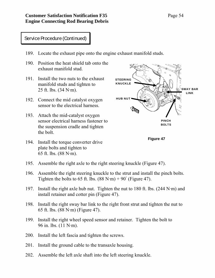
195. Assemble the right axle to the right steering knuckle (Figure 47).
196. Assemble the right steering knuckle to the strut and install the pinch bolts. Tighten the bolts to 65 ft. lbs. (88 N·m) + 90◦ (Figure 47).
197. Install the right axle hub nut. Tighten the nut to 180 ft. lbs. (244 N·m) and install retainer and cotter pin (Figure 47).
198. Install the right sway bar link to the right front strut and tighten the nut to 65 ft. lbs. (88 N·m) (Figure 47).
199. Install the right wheel speed sensor and retainer. Tighten the bolt to 96 in. lbs. (11 N·m).
200. Install the left fascia and tighten the screws.
201. Install the ground cable to the transaxle housing.
202. Assemble the left axle shaft into the left steering knuckle.
Service Procedure (Continued)
Customer Satisfaction Notification F35 Page 55 Engine Connecting Rod Bearing Debris
203. Assemble the left steering knuckle to the left strut. Install the pinch bolts
and tighten the bolts to 65 ft. lbs. (88 N·m) + 90◦ (Figure 47).
204. Install the left axle hub nut. Tighten the nut to 180 ft. lbs. (244 N·m) and install retainer and cotter pin.
205. Install the left sway bar link to the left front strut. Tighten the nut to 65 ft. lbs. (88 N·m) (Figure 47).
206. Install the left wheel speed sensor and retainer. Tighten the bolt to 8 ft. lbs. (11 N·m).
207. Connect the engine wire harness to the PCM.
208. Install both the right and left inner fender liners.
209. Install the right and left wheel/tire assemblies and tighten the lug nuts to 110 ft. lbs. (149 N·m).
210. Lower the vehicle.
211. Connect the front oxygen sensor to the electrical wire harness.
212. Connect the engine harness to the chassis harness.
213. Attach the starter electrical harness to the starter.
214. Connect the duty cycle purge solenoid to the electrical harness.
215. Connect the generator to the electrical harness.
216. Connect the air conditioning clutch to the electrical harness.
217. Remove the caps from the air conditioning compressor and lines. Install the lines to the air conditioning compressor and tighten the fasteners to 204 in. lbs. (23 N·m).
218. Install the front right and left brake lines. Remove the prop from the brake pedal.
219. Install the heater hoses.
Service Procedure (Continued)
Customer Satisfaction Notification F35 Page 56 Engine Connecting Rod Bearing Debris
220. Install the hose to the coolant recovery bottle.
221. Install the block heater (if so equipped) 110 v power cord to the heater element.
222. Connect the transaxle oil cooler lines at the radiator.
223. Connect the transaxle selector shifter cable.
224. Install the engine wire harness ground at the left inner frame rail.
225. Install the transaxle electrical harness clip into the transaxle housing.
226. Connect the transaxle solenoid packs to the electrical harness.
227. Connect the transaxle range sensor to the electrical harness.
228. Connect the transaxle output speed sensor to the electrical harness.
229. Connect the transaxle multi-pin connector to the electrical harness.
230. Connect the vacuum lines to the intake manifold (brake booster, speed control servo, HVAC, etc).
231. Connect the throttle cables to the throttle body.
232. Install the lower radiator hose.
233. Install the air cleaner box.
234. Connect the wire harness to the air temperature sensor located in the air cleaner box.
235. Install the upper radiator hose.
236. Install the radiator cooling fans.
237. Install the radiator core support.
238. Install the cruise control solenoid and vacuum reservoir. Tighten the fasteners.
Service Procedure (Continued)
Customer Satisfaction Notification F35 Page 57 Engine Connecting Rod Bearing Debris
239. Connect the cruise control cable to the throttle body.
240. Bleed and fill the cooling system.
241. Bleed and fill the brake system.
242. Remove the caps from the fuel lines.
243. Connect the chassis fuel line to the engine fuel rail.
244. Install a new oil filter.
245. Install 5½ quarts of new 10W30 engine oil.
246. Connect the battery.
247. Start the engine and check for leaks.
248. Raise the vehicle while the engine is idling.
249. Carefully tighten ONLY THE LOWER TWO air conditioning compressor bolts to 200 in. lbs. (23 N·m).
WARNING: Keep hands and tools away from the moving serpentine belt while tightening the air conditioning compressor mounting bolts.
250. Lower the vehicle and turn off the ignition.
251. Raise the vehicle and tighten the four air conditioning compressor bolts to 200 in. lbs. (23 N·m).
252. Install the right wheel well lower splash shield.
253. Lower the vehicle.
254. Evacuate and charge the air conditioning system.
255. Install engine trim cover.
256. Return vehicle to the customer.
Service Procedure (Continued)
Customer Satisfaction Notification F35 Page 58 Engine Connecting Rod Bearing Debris
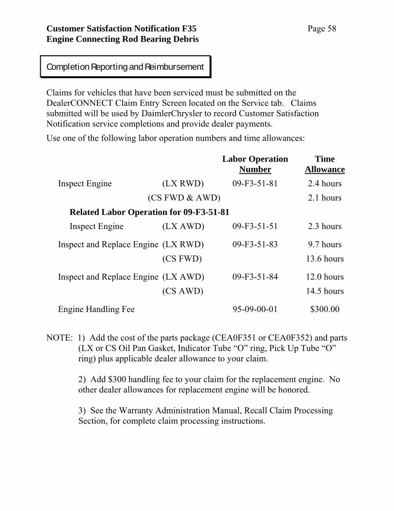
Claims for vehicles that have been serviced must be submitted on the DealerCONNECT Claim Entry Screen located on the Service tab. Claims submitted will be used by DaimlerChrysler to record Customer Satisfaction Notification service completions and provide dealer payments. Use one of the following labor operation numbers and time allowances: Labor Operation Time Number Allowance Inspect Engine (LX RWD) 09-F3-51-81 2.4 hours (CS FWD & AWD) 2.1 hours
Related Labor Operation for 09-F3-51-81 Inspect Engine (LX AWD) 09-F3-51-51 2.3 hours
Inspect and Replace Engine (LX RWD) 09-F3-51-83 9.7 hours (CS FWD) 13.6 hours
Inspect and Replace Engine (LX AWD) 09-F3-51-84 12.0 hours (CS AWD) 14.5 hours
Engine Handling Fee 95-09-00-01 $300.00
NOTE: 1) Add the cost of the parts package (CEA0F351 or CEA0F352) and parts
(LX or CS Oil Pan Gasket, Indicator Tube “O” ring, Pick Up Tube “O” ring) plus applicable dealer allowance to your claim. 2) Add $300 handling fee to your claim for the replacement engine. No other dealer allowances for replacement engine will be honored. 3) See the Warranty Administration Manual, Recall Claim Processing Section, for complete claim processing instructions.
Completion Reporting and Reimbursement
Customer Satisfaction Notification F35 Page 59 Engine Connecting Rod Bearing Debris
Removed engine assemblies must be returned to the Warranty Material Return Center.
Regional offices will receive an electronic list of involved vehicles. The Vehicle List is arranged by Dealer code and in Vehicle Identification Number (VIN) sequence. The lists are for Dealer reference in arranging for service of involved vehicles.
All involved vehicle owners should be notified of the service requirement by their
Dealer. Owners are requested to schedule appointments for this service. A sample copy of the owner notification letter is attached.
All involved vehicles have been entered into the Global Recall System (GRS) and Vehicle Information Plus (VIP) for Dealer inquiry as needed. GRS provides involved Dealers with an updated VIN list of their incomplete vehicles. Completed vehicles are removed from GRS within several days of repair claim submission. Dealers must perform this repair on all unsold vehicles before retail delivery. Dealers should also use the VIN list to follow up with all owners to schedule appointments for this repair.
Parts Return
Dealer Notification and Vehicle List
Owner Notification and Service Scheduling
Vehicle Lists, Global Recall System, VIP and Dealer Follow up
Customer Satisfaction Notification F35 Page 60 Engine Connecting Rod Bearing Debris
If you have any questions or need assistance in completing this action, please contact your International Service and Parts manager.
International Service and Parts DaimlerChrysler Corporation
Additional Information
CUSTOMER SATISFACTION NOTIFICATION F35 ENGINE CONNECTING ROD BEARING DEBRIS
Dear: (Name)
Customer satisfaction is very important to DaimlerChrysler. Accordingly, we are recommending the following service on some 2006 model year Chrysler 300 and Pacifica, Dodge Magnum and Charger vehicles equipped with a 3.5L engine.
The problem is... The engine in your vehicle (VIN: xxxxxxxxxxxxxxxxx) may have been assembled with sand-like debris on the number two connecting rod bearing journal of the crankshaft. This can cause excessive rod bearing wear and result in engine failure.
What your dealer will do...
DaimlerChrysler will repair your vehicle free of charge (parts and labor). To do this, your dealer will inspect the number two connecting rod bearing and crankshaft journal and, if necessary, replace the engine in your vehicle. The engine inspection will take about 5 hours to complete. If the engine requires replacement, another 10 hours will be needed. However, additional time may be necessary depending on how dealer appointments are scheduled and processed.
What you must do...
Simply contact your dealer right away to schedule a service appointment. Ask the dealer to hold the parts for your vehicle or to order them before your appointment. Remember to bring this letter with you to your dealer.
If you need help... If you have trouble getting your vehicle serviced, please contact the DaimlerChrysler Distributor nearest your location. A representative will assist you in getting your vehicle serviced. This information can be found in the Customer Assistance section of your Owner's Manual.
If you have already experienced the problem described above and have paid to have it repaired, contact the DaimlerChrysler Distributor nearest your location for reimbursement procedures. We're sorry for any inconvenience, but we believe that this service will help to ensure your continuing satisfaction with your vehicle. Thank you for your attention to this important matter.
International Service and Parts DaimlerChrysler Corporation
Notification Code F35