customer satisfaction notification v46 solenoid pack · customer satisfaction notification v46 –...
TRANSCRIPT
Copyright 2019, FCA US LLC, All Rights Reserved (kka)
November 2019 Dealer Service Instructions for:
Customer Satisfaction Notification V46
Solenoid Pack
2016-2017 (VF) Ram ProMaster
NOTE: This campaign applies only to the above vehicles equipped with a 6-Speed
Automatic 62TE Transmission (sales code DG2).
IMPORTANT: Many of the vehicles within the above build period have already
been inspected or repaired and, therefore, have been excluded from this
campaign.
The transmission solenoid coil terminals on about 33,000 of the above vehicles
were built out of specifications, resulting in excessive interference between the
solenoid and its mating connection. This interference created stress within the
terminals and an intermittent electrical connection. This condition may cause the
transmission to be limited to one gear and maximum speed of 30 - 45 mph and will
illuminate the Malfunction Indicator Lamp (MIL) on the instrument cluster and set
DTC P076A code.
Remedy Available
IMPORTANT: Some of the involved vehicles may be in dealer used vehicle
inventory. Dealers should complete this campaign service on these vehicles
before retail delivery. Dealers should also perform this campaign on vehicles in
for service. Involved vehicles can be determined by using the VIP inquiry process.
Subject
Customer Satisfaction Notification V46 – Solenoid Pack Page 2
The transmission solenoid pack must be replaced on all involved vehicles.
Part Number Description
CCDHV461AA Part Package
Each package contains the following components:
Quantity Description
1 Module, Solenoid 62TE
1 I-Sheet Service
05010884AD Sealant, Standard RTV
68218057AC ATF+ 4 (3 Quarts Required)
Dealers should order the part package for each vehicle at the time appointments are
scheduled to assure that the part is available when the customer arrives.
No parts return required for this campaign.
The following special tool is required to perform this repair:
NPN wiTECH micro pod II
NPN Laptop Computer
NPN wiTECH Software
8874A Trans Cooler Line Disconnect
9336A Oil Dipstick
Repair
Parts Information
Parts Return
Special Tools
Customer Satisfaction Notification V46 – Solenoid Pack Page 3
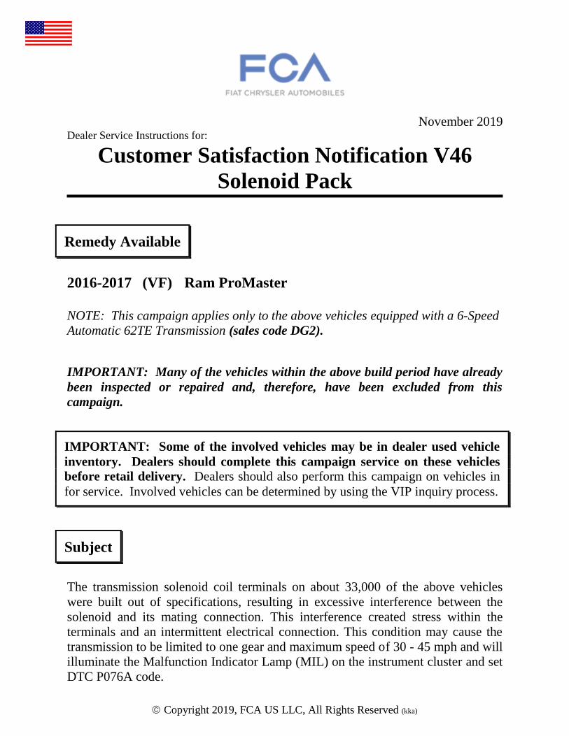
1. Remove the floor mat and the battery storage access cover, disconnect and
isolate the negative battery cable terminal from the battery post (Figure 1).
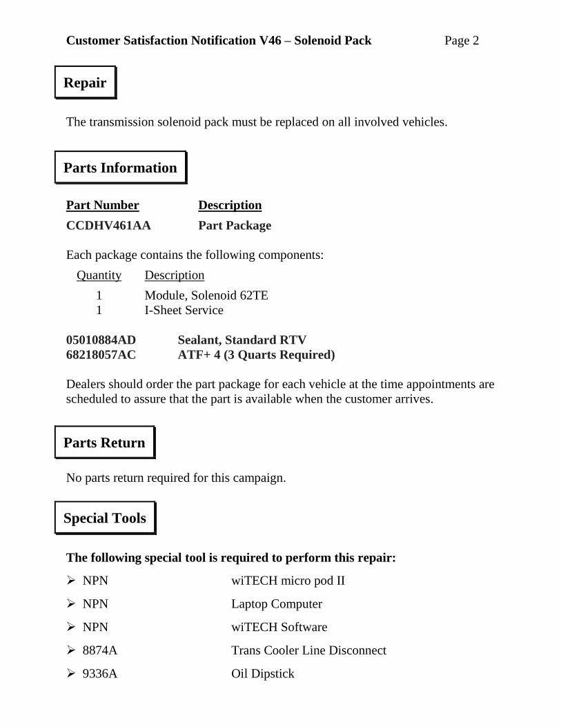
2. Disconnect the oil cooler
lines from transaxle
using Trans Cooler
Line Disconnect 8875A
(Figure 2).
3. Position oil cooler
lines aside away from the
valve body pan.
4. Disconnect the shift
cable from the manual
lever (Figure 2).
Service Procedure
Figure 1 – Battery Storage
BATTERY STORAGE COVER
BATTERY GROUND CABLE
Figure 2 – Trans Cooler Lines
TRANS COOLER LINES
SHIFT CABLE
MANUAL LEVER
Customer Satisfaction Notification V46 – Solenoid Pack Page 4
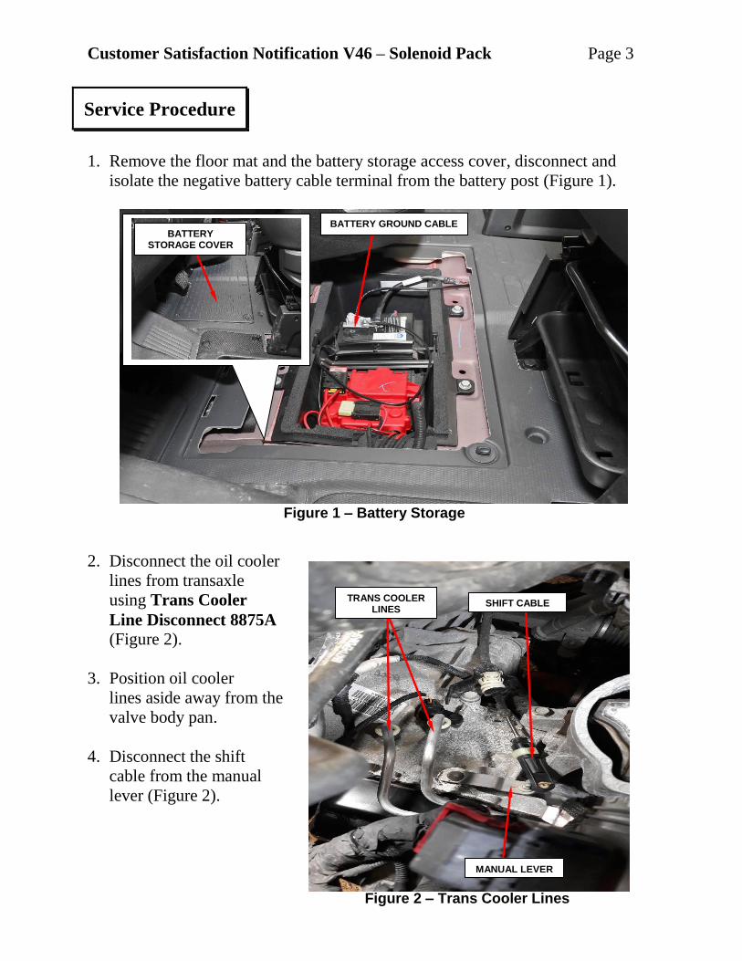
5. Disconnect the fir tree
retainer from the trans
oil pan (Figure 3).
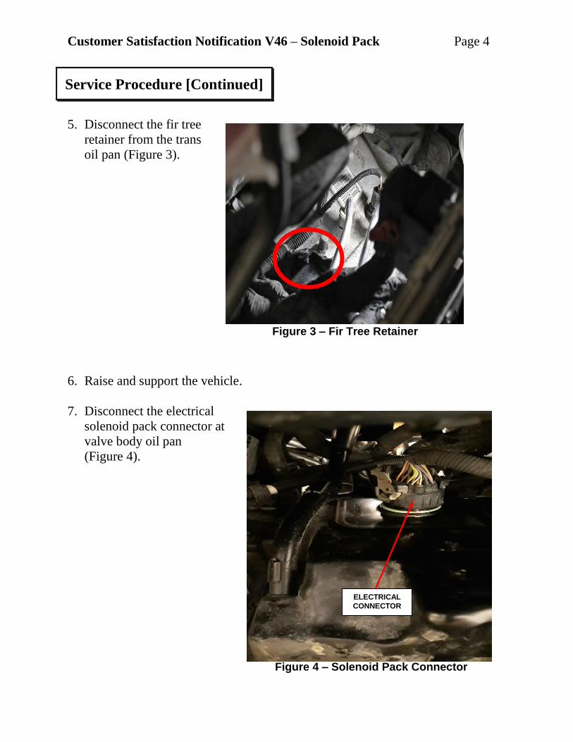
6. Raise and support the vehicle.
7. Disconnect the electrical
solenoid pack connector at
valve body oil pan
(Figure 4).
Service Procedure [Continued]
Figure 4 – Solenoid Pack Connector
Figure 3 – Fir Tree Retainer
ELECTRICAL
CONNECTOR
Customer Satisfaction Notification V46 – Solenoid Pack Page 5
8. If equipped, remove the front lower closeout.
9. If equipped, remove the fasteners and the Front Sound Damper Cover.
10. Remove the top valve body oil pan bolts.
11. Remove the lower valve body oil pan bolts and drain transmission fluid.
12. Remove the valve body oil pan.
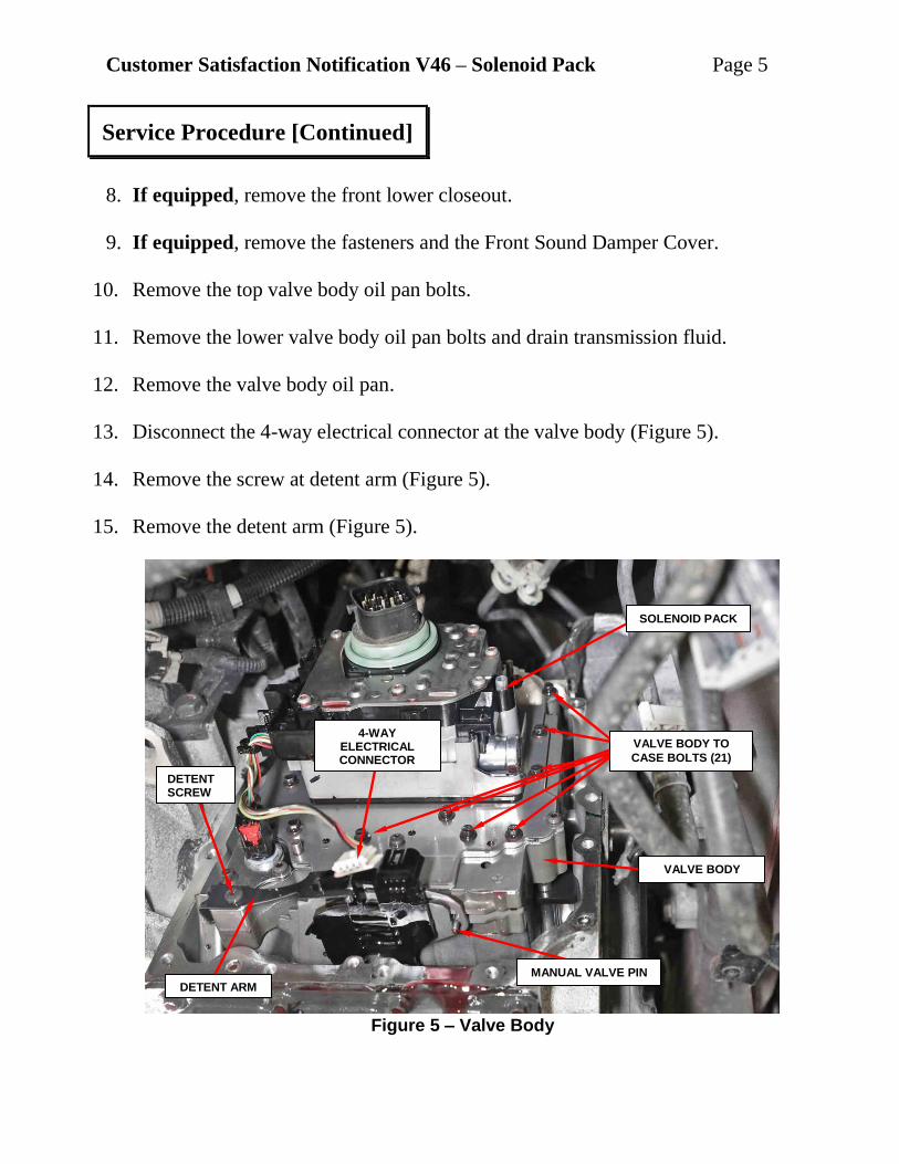
13. Disconnect the 4-way electrical connector at the valve body (Figure 5).
14. Remove the screw at detent arm (Figure 5).
15. Remove the detent arm (Figure 5).
Service Procedure [Continued]
Figure 5 – Valve Body
DETENT ARM
4-WAY ELECTRICAL CONNECTOR
VALVE BODY
SOLENOID PACK
VALVE BODY TO
CASE BOLTS (21)
MANUAL VALVE PIN
DETENT SCREW
Customer Satisfaction Notification V46 – Solenoid Pack Page 6
16. Remove the twenty-one valve body to case bolts (Figure 5).
17. Verify the manual lever is fully forward to keep the manual valve pin from
binding (Figure 5).
18. Pull the valve body away from the underdrive compounder assembly oil
transfer tubes and lift up on valve body to clear the manual valve pin past the
slot in the rooster comb (Figure 5).
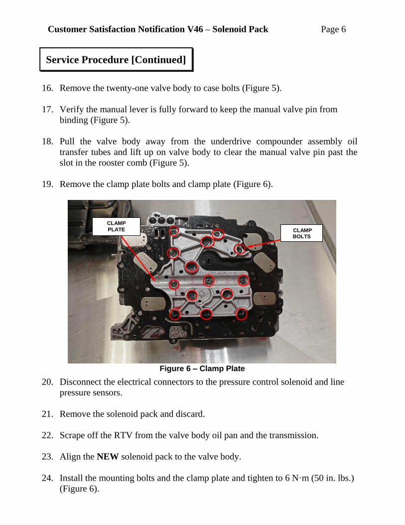
19. Remove the clamp plate bolts and clamp plate (Figure 6).
20. Disconnect the electrical connectors to the pressure control solenoid and line
pressure sensors.
21. Remove the solenoid pack and discard.
22. Scrape off the RTV from the valve body oil pan and the transmission.
23. Align the NEW solenoid pack to the valve body.
24. Install the mounting bolts and the clamp plate and tighten to 6 N·m (50 in. lbs.)
(Figure 6).
Service Procedure [Continued]
Figure 6 – Clamp Plate
CLAMP
PLATE CLAMP BOLTS
Customer Satisfaction Notification V46 – Solenoid Pack Page 7
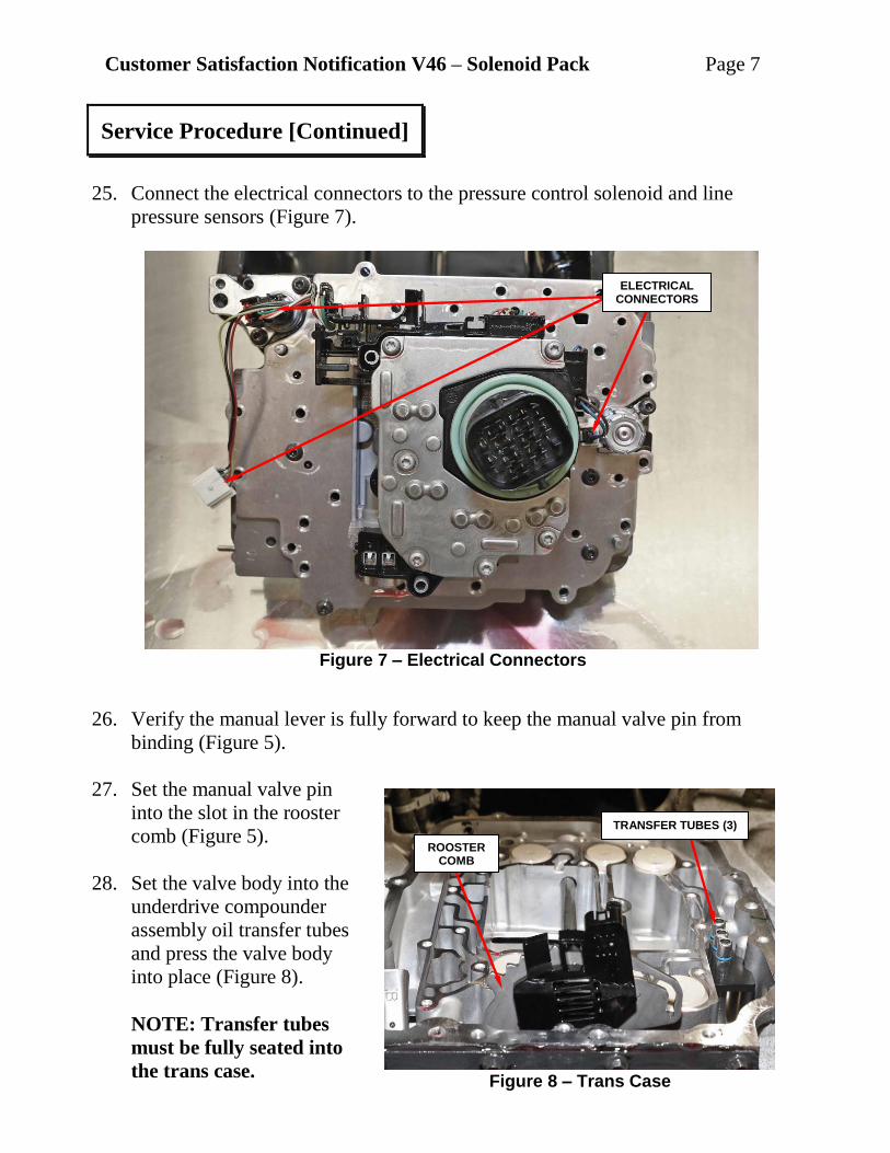
25. Connect the electrical connectors to the pressure control solenoid and line
pressure sensors (Figure 7).
26. Verify the manual lever is fully forward to keep the manual valve pin from
binding (Figure 5).
27. Set the manual valve pin
into the slot in the rooster
comb (Figure 5).
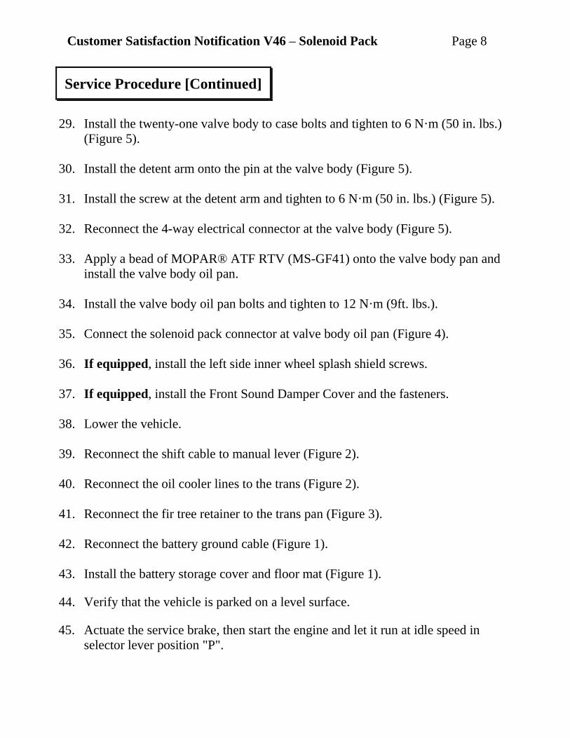
28. Set the valve body into the
underdrive compounder
assembly oil transfer tubes
and press the valve body
into place (Figure 8).
NOTE: Transfer tubes
must be fully seated into
the trans case.
Service Procedure [Continued]
Figure 7 – Electrical Connectors
ELECTRICAL CONNECTORS
Figure 8 – Trans Case
TRANSFER TUBES (3)
ROOSTER COMB
Customer Satisfaction Notification V46 – Solenoid Pack Page 8
29. Install the twenty-one valve body to case bolts and tighten to 6 N·m (50 in. lbs.)
(Figure 5).
30. Install the detent arm onto the pin at the valve body (Figure 5).
31. Install the screw at the detent arm and tighten to 6 N·m (50 in. lbs.) (Figure 5).
32. Reconnect the 4-way electrical connector at the valve body (Figure 5).
33. Apply a bead of MOPAR® ATF RTV (MS-GF41) onto the valve body pan and
install the valve body oil pan.
34. Install the valve body oil pan bolts and tighten to 12 N·m (9ft. lbs.).
35. Connect the solenoid pack connector at valve body oil pan (Figure 4).
36. If equipped, install the left side inner wheel splash shield screws.
37. If equipped, install the Front Sound Damper Cover and the fasteners.
38. Lower the vehicle.
39. Reconnect the shift cable to manual lever (Figure 2).
40. Reconnect the oil cooler lines to the trans (Figure 2).
41. Reconnect the fir tree retainer to the trans pan (Figure 3).
42. Reconnect the battery ground cable (Figure 1).
43. Install the battery storage cover and floor mat (Figure 1).
44. Verify that the vehicle is parked on a level surface.
45. Actuate the service brake, then start the engine and let it run at idle speed in
selector lever position "P".
Service Procedure [Continued]
Customer Satisfaction Notification V46 – Solenoid Pack Page 9
46. Shift through the transmission modes several times with the vehicle stationary
and the engine idling.
47. Remove the dipstick tube cap.
48. Add approximately 3 quarts of ATF+ 4 to transmission.
WARNINIG: There is a risk of accident from vehicle moving when the
engine is running. Secure vehicle to prevent it from moving. There is a risk
of injury from contusions and burns if you insert your hands into the
engine when it is running. Do not touch hot or rotating parts. Wear
properly fitted work clothes.
49. Connect the wiTECH diagnostic tool to the vehicle.
50. Monitor the transmission oil temperature, once temperature has reached above
60 (°F) °16C, check the transmission oil level, and add as needed.
NOTE: When inserting dipstick special tool 9336A , excess insertion force
may cause the dipstick to slip past the stop on the bracket in the
transmission oil pan. An approximate distance that the dipstick should be
inserted into the fill tube is 424 mm (16.69 in.
51. Warm up the transmission, wait at least 2 minutes and check the oil level with
the engine running. Push the OIL Dipstick 9336A into transmission fill tube
until the dipstick tip contacts the oil pan and pull out again, read off oil level,
repeat if necessary.
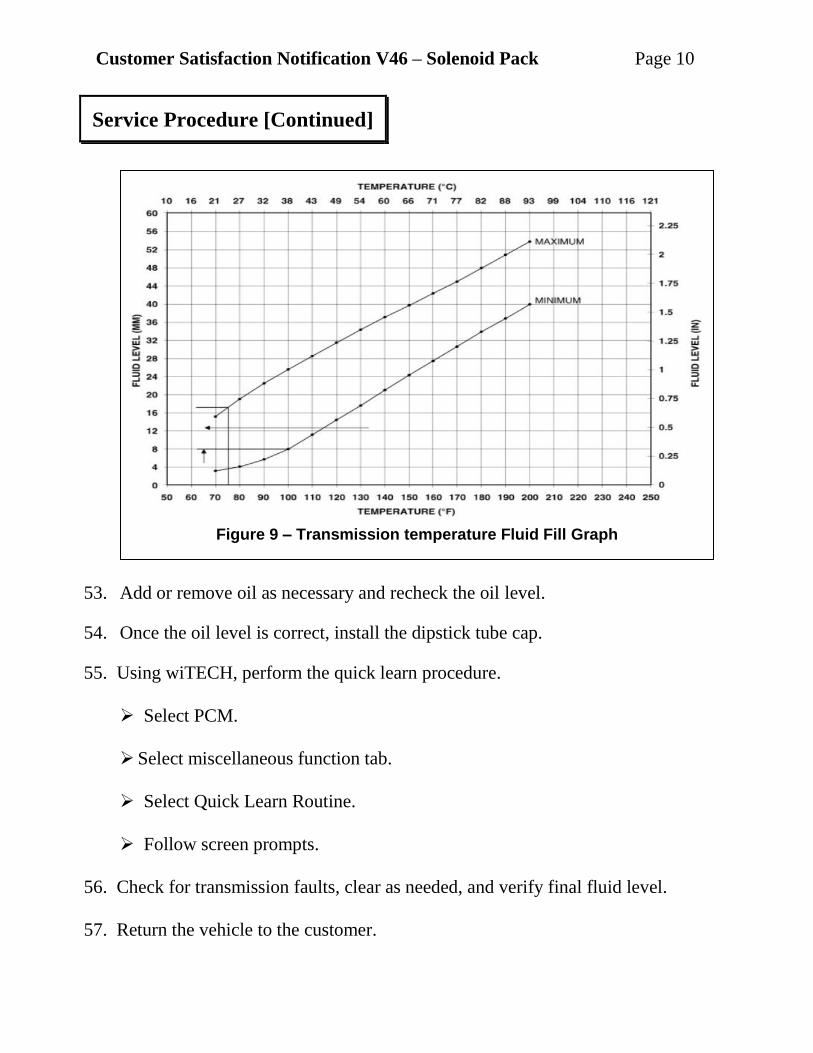
52. The transmission Oil Dipstick 9336A has indicator marks every 10 mm.
Determine the height of the oil level on the dipstick and using the height, the
Transmission Fluid Temperature (TFT) as viewed with the scan tool, and the
Transmission Fluid Graph, determine if the transmission oil level is correct
(Figure 9).
Service Procedure [Continued]
Customer Satisfaction Notification V46 – Solenoid Pack Page 10
53. Add or remove oil as necessary and recheck the oil level.
54. Once the oil level is correct, install the dipstick tube cap.
55. Using wiTECH, perform the quick learn procedure.
Select PCM.
Select miscellaneous function tab.
Select Quick Learn Routine.
Follow screen prompts.
56. Check for transmission faults, clear as needed, and verify final fluid level.
57. Return the vehicle to the customer.
Service Procedure [Continued]
Figure 9 – Transmission temperature Fluid Fill Graph
Customer Satisfaction Notification V46 – Solenoid Pack Page 11
This campaign is subject to the State of California Registration
Renewal/Emissions Recall Enforcement Program. Complete a Vehicle
Emission Recall Proof of Correction Form (Form No. 81-016-1053) and supply it
to vehicle owners residing in the state of California for proof that this campaign
has been performed when they renew the vehicle registration.
Process Steps to obtain the California Proof of Correction form:
a. Access the “DealerCONNECT” website.
b. Select the “Service” tab.
c. Under the “Publications” heading, select the “ePublishing” link.
d. Sign in using your Dealer Code and Password.
e. Select the “Proof of Correction form”.
Claims for vehicles that have been serviced must be submitted on the
DealerCONNECT Claim Entry Screen located on the Service tab. Claims paid
will be used by FCA to record Customer Satisfaction Notification service
completions and provide dealer payments.
Use the following labor operation number and time allowance:
Labor Operation Time
Number Allowance
Replace Solenoid Pack 21-V4-61-82 2.6 hours
Add the cost of the parts package plus applicable dealer allowance to your claim.
NOTE: See the Warranty Administration Manual, Recall Claim Processing
Section, for complete claim processing instructions.
Complete Proof of Correction Form for California Residents
Completion Reporting and Reimbursement
Customer Satisfaction Notification V46 – Solenoid Pack Page 12
To view this notification on DealerCONNECT, select “Global Recall System” on
the Service tab, then click on the description of this notification.
All involved vehicle owners known to FCA are being notified of the service
requirement by mail. They are requested to schedule appointments for this service
with their dealers. A generic copy of the owner letter is attached.
All involved vehicles have been entered into the DealerCONNECT Global Recall
System (GRS) and Vehicle Information Plus (VIP) for dealer inquiry as needed.
GRS provides involved dealers with an updated VIN list of their incomplete
vehicles. The owner’s name, address and phone number are listed if known.
Completed vehicles are removed from GRS within several days of repair claim
submission.
To use this system, click on the “Service” tab and then click on “Global Recall
System.” Your dealer’s VIN list for each recall displayed can be sorted by: those
vehicles that were unsold at campaign launch, those with a phone number, city, zip
code, or VIN sequence.
Dealers should perform this repair on all unsold vehicles before retail
delivery. Dealers should also use the VIN list to follow up with all owners to
schedule appointments for this repair.
VIN lists may contain confidential, restricted owner name and address information that was
obtained from the Department of Motor Vehicles of various states. Use of this information is
permitted for this notification only and is strictly prohibited from all other use.
If you have any questions or need assistance in completing this action, please
contact your Service and Parts District Manager.
Customer Service / Field Operations
FCA US LLC
Dealer Notification
Owner Notification and Service Scheduling
Vehicle Lists, Global Recall System, VIP and Dealer Follow Up
Additional Information
This notice applies to your vehicle,
V46
YOUR SCHEDULING OPTIONS
1. RECOMMENDED OPTION
Call your authorized Chrysler /
Dodge / Jeep® / RAM Dealership
2. Call the FCA Recall Assistance
Center at 1-800-853-1403. An
agent can confirm part
availability and help schedule an
appointment
3. Visit recalls.mopar.com, scan the
QR code below, or download the
Mopar Owner’s Companion App.
Get access to recall notifications,
locate your nearest dealer, and more
through this website or Mopar
Owner’s Companion App. You will be
asked to provide your Vehicle
Identification Number (VIN) to
protect and verify your identity.
DEALERSHIP INSTRUCTIONS
Please reference CSN V46.
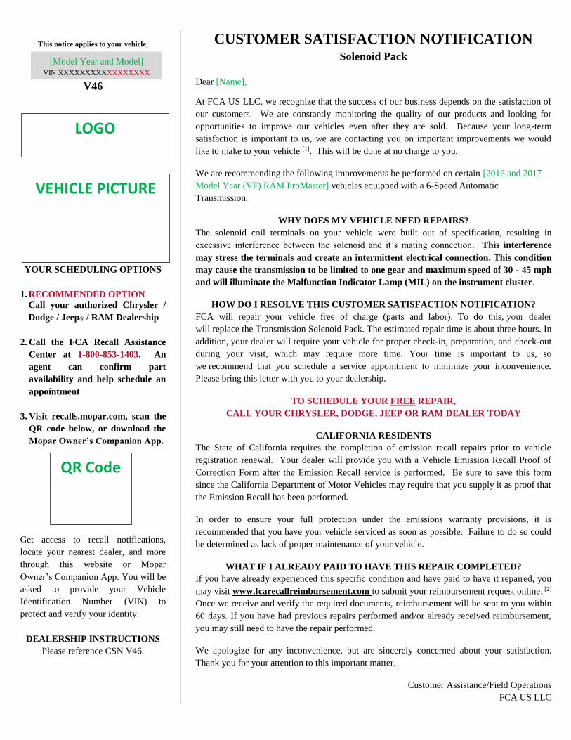
CUSTOMER SATISFACTION NOTIFICATION Solenoid Pack
Dear [Name],
At FCA US LLC, we recognize that the success of our business depends on the satisfaction of
our customers. We are constantly monitoring the quality of our products and looking for
opportunities to improve our vehicles even after they are sold. Because your long-term
satisfaction is important to us, we are contacting you on important improvements we would
like to make to your vehicle [1]. This will be done at no charge to you.
We are recommending the following improvements be performed on certain [2016 and 2017
Model Year (VF) RAM ProMaster] vehicles equipped with a 6-Speed Automatic
Transmission.
WHY DOES MY VEHICLE NEED REPAIRS?
The solenoid coil terminals on your vehicle were built out of specification, resulting in
excessive interference between the solenoid and it’s mating connection. This interference
may stress the terminals and create an intermittent electrical connection. This condition
may cause the transmission to be limited to one gear and maximum speed of 30 - 45 mph
and will illuminate the Malfunction Indicator Lamp (MIL) on the instrument cluster.
HOW DO I RESOLVE THIS CUSTOMER SATISFACTION NOTIFICATION?
FCA will repair your vehicle free of charge (parts and labor). To do this, your dealer
will replace the Transmission Solenoid Pack. The estimated repair time is about three hours. In
addition, your dealer will require your vehicle for proper check-in, preparation, and check-out
during your visit, which may require more time. Your time is important to us, so
we recommend that you schedule a service appointment to minimize your inconvenience.
Please bring this letter with you to your dealership.
TO SCHEDULE YOUR FREE REPAIR,
CALL YOUR CHRYSLER, DODGE, JEEP OR RAM DEALER TODAY
CALIFORNIA RESIDENTS
The State of California requires the completion of emission recall repairs prior to vehicle
registration renewal. Your dealer will provide you with a Vehicle Emission Recall Proof of
Correction Form after the Emission Recall service is performed. Be sure to save this form
since the California Department of Motor Vehicles may require that you supply it as proof that
the Emission Recall has been performed.
In order to ensure your full protection under the emissions warranty provisions, it is
recommended that you have your vehicle serviced as soon as possible. Failure to do so could
be determined as lack of proper maintenance of your vehicle.
WHAT IF I ALREADY PAID TO HAVE THIS REPAIR COMPLETED?
If you have already experienced this specific condition and have paid to have it repaired, you
may visit www.fcarecallreimbursement.com to submit your reimbursement request online. [2]
Once we receive and verify the required documents, reimbursement will be sent to you within
60 days. If you have had previous repairs performed and/or already received reimbursement,
you may still need to have the repair performed.
We apologize for any inconvenience, but are sincerely concerned about your satisfaction.
Thank you for your attention to this important matter.
Customer Assistance/Field Operations
FCA US LLC
VEHICLE PICTURE
LOGO
[Model Year and Model]
VIN XXXXXXXXXXXXXXXXX
QR Code
[1] If you no longer own this vehicle, please help us update our records. Call the FCA Recall Assistance Center at 1-800-853-1403 to update your information.
[2] You can also mail in your original receipts and proof of payment to the following address for reimbursement consideration: FCA Customer Assistance, P.O. Box 21-
8004, Auburn Hills, MI 48321-8007, Attention: Recall Reimbursement.
Mr. Mrs. Customer
1234 Main Street
Hometown, MI 48371