customer satisfaction notification w51 steering gear
TRANSCRIPT
Copyright 2020, FCA US LLC, All Rights Reserved(kka)
August 2020 Dealer Service Instructions for:
Customer Satisfaction Notification W51
Steering Gear
2020 (DJ) Ram 2500 Pickup
(D2) Ram 3500 Pickup
NOTE: Some vehicles above may have been identified as not involved in this
campaign and therefore have been excluded from this campaign.
The Hydraulic-Electric steering gear on about 72 of the above vehicles have been
manufactured with an insufficient amount of grease. Lack of grease may cause a
gritty or non-smooth feel in the steering wheel when turning.
Replace the steering gear and the required associated fasteners, set toe to
specification.
Remedy Available
IMPORTANT: Some of the involved vehicles may be in dealer new vehicle
inventory. Dealers should also consider this requirement to apply to used vehicle
inventory and should perform this campaign on vehicles in for service. Involved
vehicles can be determined by using the VIP inquiry process.
Subject
Repair
Customer Satisfaction Notification W51 – Steering Gear Page 2
Part Number Description
CCALW511AA Part Package
Each package contains the following components:
Quantity Description
1 Steering Gear
1 Bolt, Pinch Intermediate Shaft
1 Nut, Pitman Arm
68218057AC Fluid (ATF), Power Steering (MSQ of 6)
06510495AA Washer, Pressure Hose to Pump (MSQ of 10)
Return the Steering Gear to the Mopar Core Return Center for core credit.
The following special tools are required to perform this repair:
NPN wiTECH MicroPod II
NPN Laptop Computer
NPN wiTECH Software
NPN Puller, Pitman Arm
9688A Adapter, Cap PS
C-4207-A Hand Vacuum Pump or equivalent
C-3894-A Puller, Tie Rod
Parts Information
Parts Return
Special Tools
Customer Satisfaction Notification W51 – Steering Gear Page 3
A. Hydraulic-Electric Steering Gear Removal Procedure
NOTE: The steering column on vehicles with an automatic transmission
may not be equipped with an internal locking shaft that allows the ignition
key cylinder to be locked with the key. Alternative methods of locking the
steering wheel for service will have to be used.
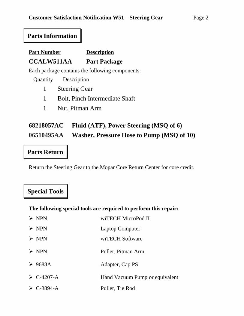
1. Disconnect the Intelligent Battery Sensor (IBS) wire harness connector.
2. Loosen the ground terminal nut and remove the negative battery cable(s) with
IBS from the battery(s) and isolate it (Figure 1).
3. Place the front wheels in a straight ahead position.
4. Lock the steering wheel.
Service Procedure
Figure 1 – Engine Compartment
IBS AND NEGATIVE BATTERY CABLE(S) (DIESEL)
POWER STEERING RESERVIOR
RADIATOR
CLOSURE
RESERVIOR CAP
Customer Satisfaction Notification W51 – Steering Gear Page 4
5. Gas Engine Equipped: Remove the air cleaner hose, and body.
6. Diesel Engine Equipped: Disconnect the Mass Air Flow (MAF) sensor wire
harness connector.
7. Diesel Engine Equipped: Disconnect the Temperature/Barometric Absolute
Pressure (T/BAP) sensor wire harness connector.
8. Diesel Engine Equipped: Detach the wire harness from the clean air hose.
9. Remove the 14 push pins and the radiator closure (Figure 1).
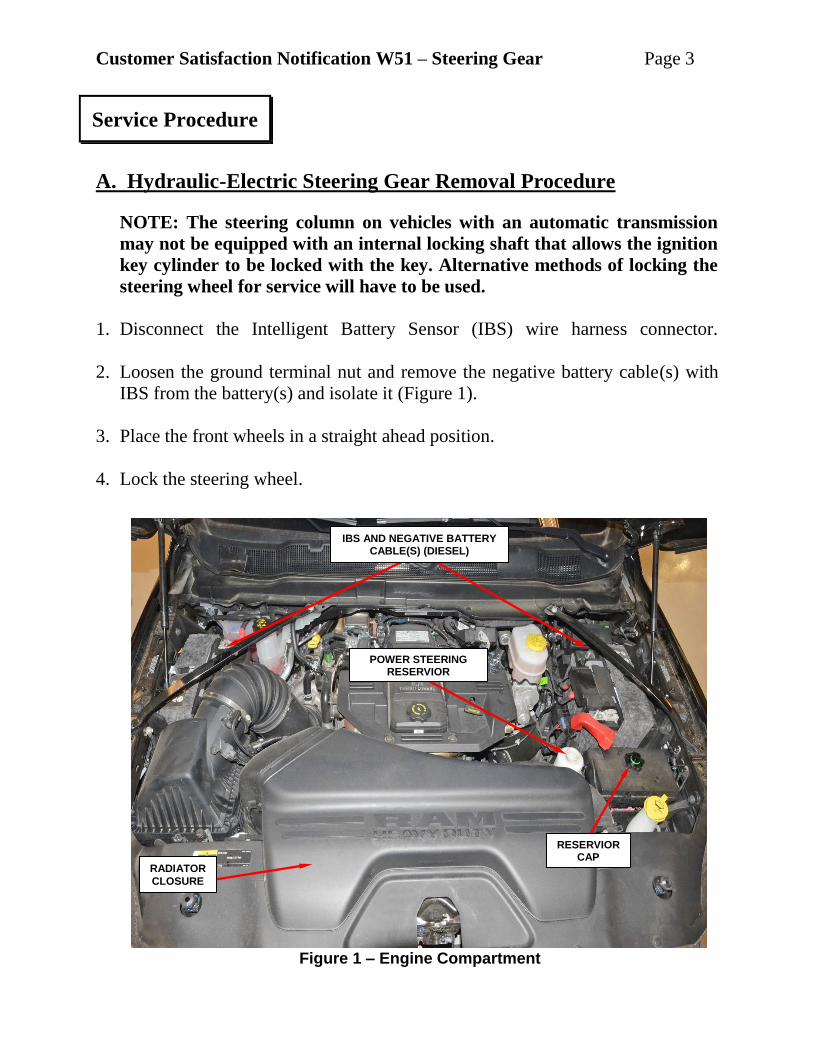
10. Remove the two bolts securing the intake air tube (Figure 2).
11. Lift up on the air cleaner body with intake air tube and remove and set aside
(Figure 2).
Service Procedure [Continued]
Figure 2 – Air Intake Tube
AIR INTAKE TUBE
BOLTS
AIR INTAKE TUBE AIR CLEANER BODY
Customer Satisfaction Notification W51 – Steering Gear Page 5
12. Drain and siphon the power steering fluid from the reservoir.
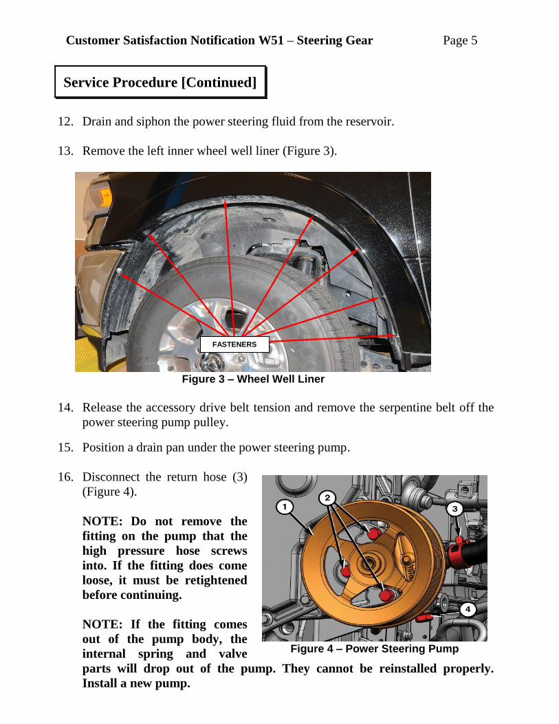
13. Remove the left inner wheel well liner (Figure 3).
14. Release the accessory drive belt tension and remove the serpentine belt off the
power steering pump pulley.
15. Position a drain pan under the power steering pump.
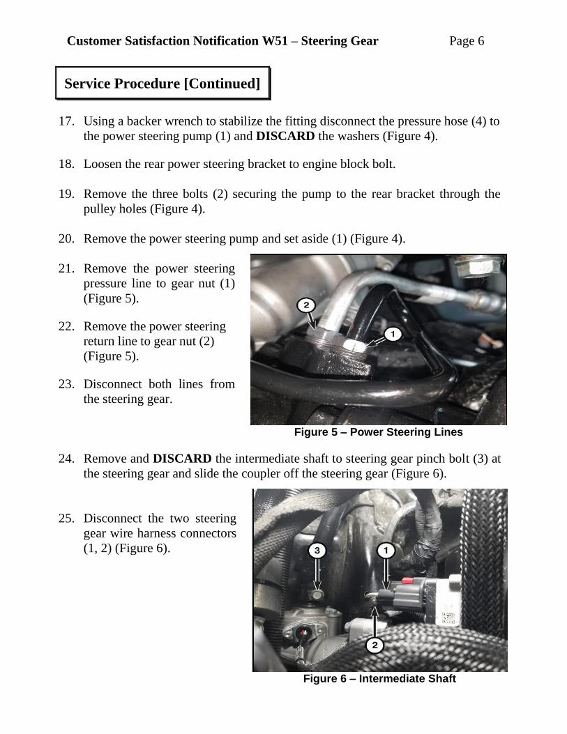
16. Disconnect the return hose (3)
(Figure 4).
NOTE: Do not remove the
fitting on the pump that the
high pressure hose screws
into. If the fitting does come
loose, it must be retightened
before continuing.
NOTE: If the fitting comes
out of the pump body, the
internal spring and valve
parts will drop out of the pump. They cannot be reinstalled properly.
Install a new pump.
Service Procedure [Continued]
Figure 3 – Wheel Well Liner
Figure 4 – Power Steering Pump
FASTENERS
Customer Satisfaction Notification W51 – Steering Gear Page 6
17. Using a backer wrench to stabilize the fitting disconnect the pressure hose (4) to
the power steering pump (1) and DISCARD the washers (Figure 4).
18. Loosen the rear power steering bracket to engine block bolt.
19. Remove the three bolts (2) securing the pump to the rear bracket through the
pulley holes (Figure 4).
20. Remove the power steering pump and set aside (1) (Figure 4).
21. Remove the power steering
pressure line to gear nut (1)
(Figure 5).
22. Remove the power steering
return line to gear nut (2)
(Figure 5).
23. Disconnect both lines from
the steering gear.
24. Remove and DISCARD the intermediate shaft to steering gear pinch bolt (3) at
the steering gear and slide the coupler off the steering gear (Figure 6).
25. Disconnect the two steering
gear wire harness connectors
(1, 2) (Figure 6).
Service Procedure [Continued]
Figure 5 – Power Steering Lines
Figure 6 – Intermediate Shaft
Customer Satisfaction Notification W51 – Steering Gear Page 7
26. Raise and support the vehicle.
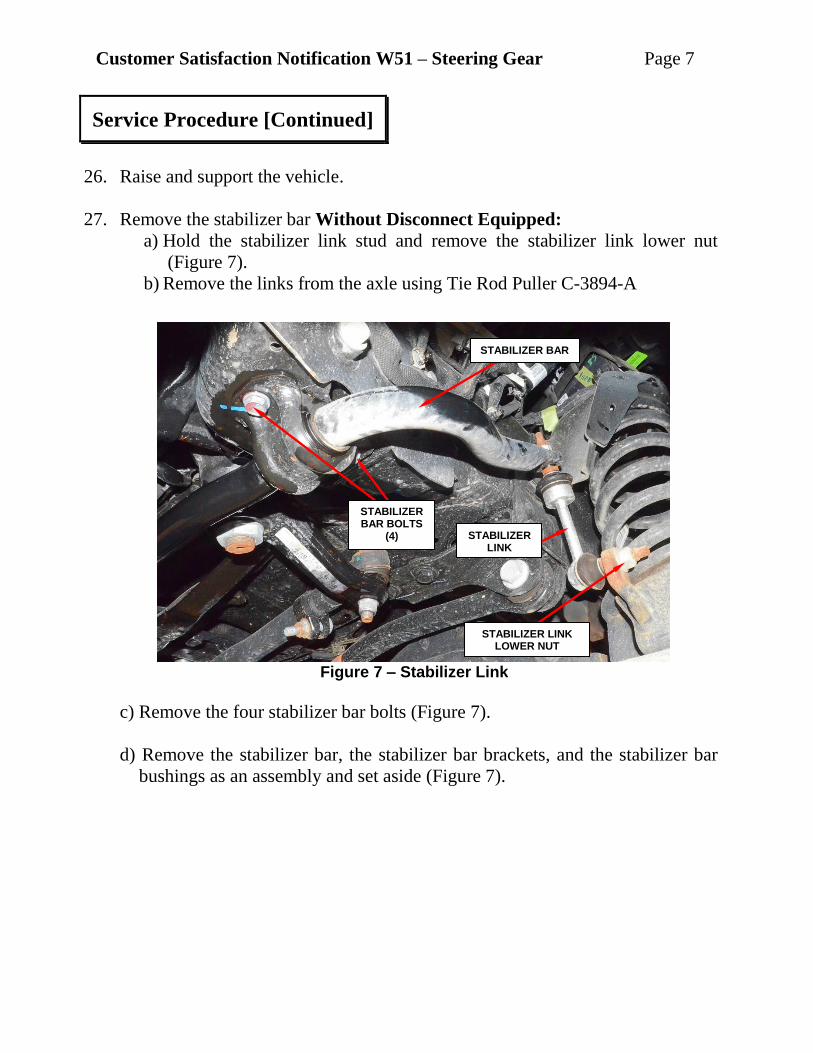
27. Remove the stabilizer bar Without Disconnect Equipped:
a) Hold the stabilizer link stud and remove the stabilizer link lower nut
(Figure 7).
b) Remove the links from the axle using Tie Rod Puller C-3894-A
c) Remove the four stabilizer bar bolts (Figure 7).
d) Remove the stabilizer bar, the stabilizer bar brackets, and the stabilizer bar
bushings as an assembly and set aside (Figure 7).
Service Procedure [Continued]
Figure 7 – Stabilizer Link
STABILIZER LINK LOWER NUT
STABILIZER BAR
STABILIZER LINK
STABILIZER BAR BOLTS
(4)
Customer Satisfaction Notification W51 – Steering Gear Page 8
NOTE: Disconnect Equipped: Before disconnecting the stabilizer bar
actuator wire harness connector, clean the outside of the connector with a
cleaner and compressed air, to remove any dirt or debris.
NOTE: Disconnect Equipped: The Final Drive Control Module (FDCM) is
integrated with the front stabilizer bar actuator.
28. Disconnect Equipped: Disconnect the stabilizer bar actuator wire harness
connector (5) (Figure 6).
WARNING: Disconnect Equipped: The disconnecting stabilizer bar unit
(3) is not serviced separately from the bar (4). Do not disassemble this unit
from the stabilizer bar
(Figure 8).
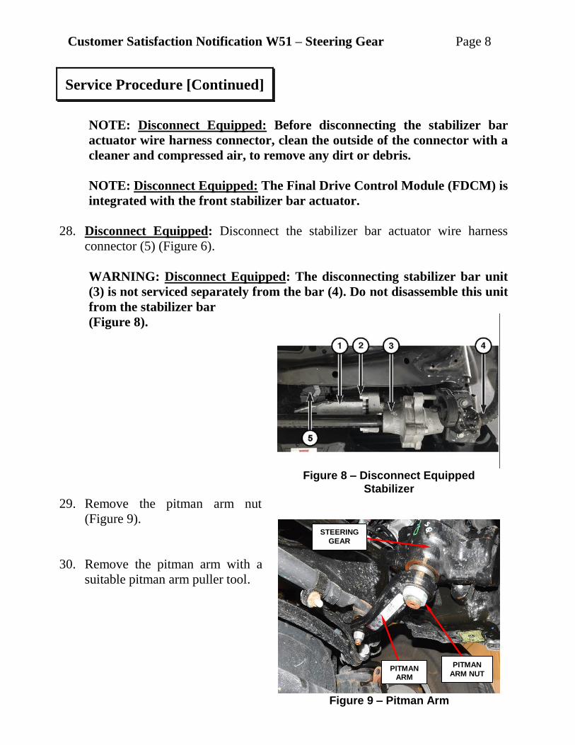
29. Remove the pitman arm nut
(Figure 9).
30. Remove the pitman arm with a
suitable pitman arm puller tool.
Service Procedure [Continued]
Figure 8 – Disconnect Equipped
Stabilizer
Figure 9 – Pitman Arm
PITMAN
ARM NUT PITMAN
ARM
STEERING
GEAR
Customer Satisfaction Notification W51 – Steering Gear Page 9
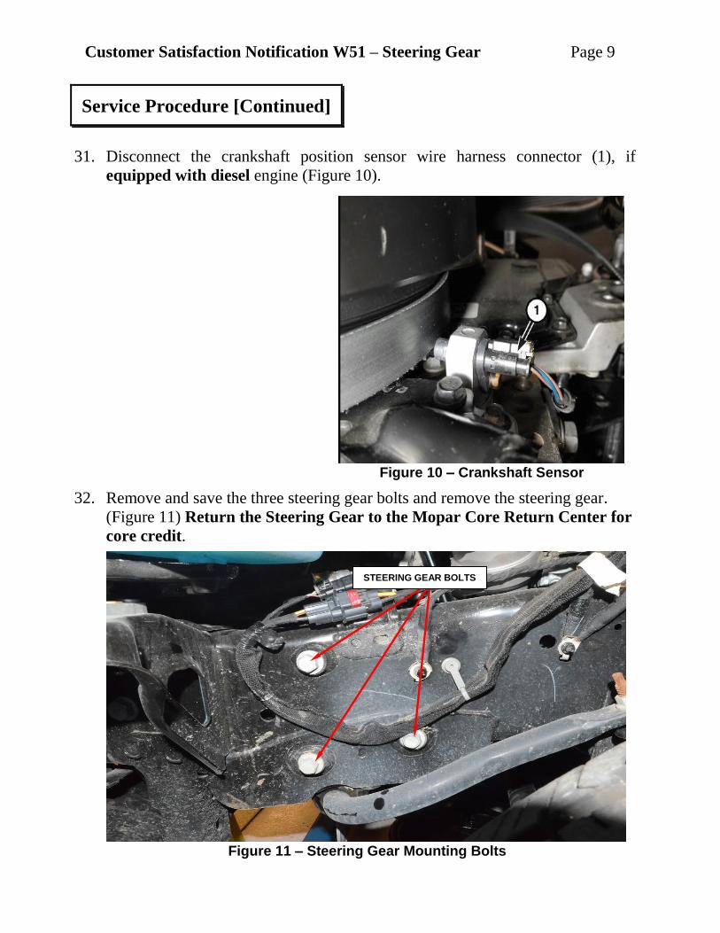
31. Disconnect the crankshaft position sensor wire harness connector (1), if
equipped with diesel engine (Figure 10).
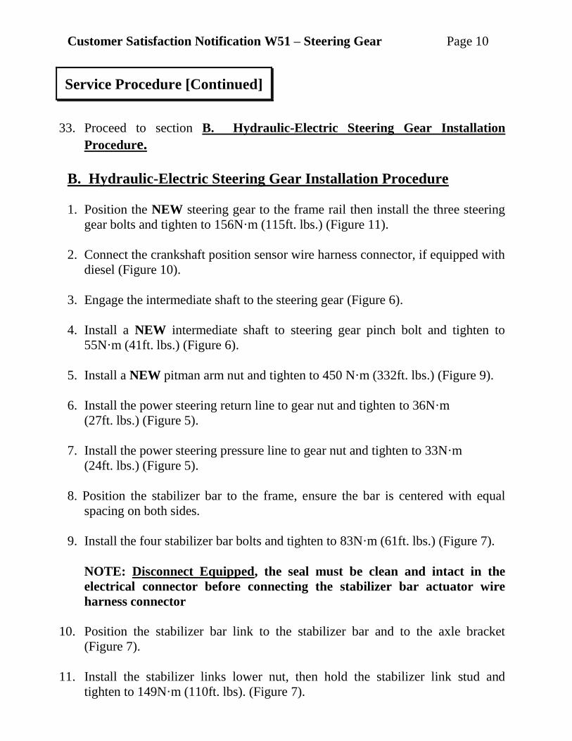
32. Remove and save the three steering gear bolts and remove the steering gear.
(Figure 11) Return the Steering Gear to the Mopar Core Return Center for
core credit.
Service Procedure [Continued]
Figure 11 – Steering Gear Mounting Bolts
Figure 10 – Crankshaft Sensor
STEERING GEAR BOLTS
Customer Satisfaction Notification W51 – Steering Gear Page 10
33. Proceed to section B. Hydraulic-Electric Steering Gear Installation
Procedure.
B. Hydraulic-Electric Steering Gear Installation Procedure
1. Position the NEW steering gear to the frame rail then install the three steering
gear bolts and tighten to 156N·m (115ft. lbs.) (Figure 11).
2. Connect the crankshaft position sensor wire harness connector, if equipped with
diesel (Figure 10).
3. Engage the intermediate shaft to the steering gear (Figure 6).
4. Install a NEW intermediate shaft to steering gear pinch bolt and tighten to
55N·m (41ft. lbs.) (Figure 6).
5. Install a NEW pitman arm nut and tighten to 450 N·m (332ft. lbs.) (Figure 9).
6. Install the power steering return line to gear nut and tighten to 36N·m
(27ft. lbs.) (Figure 5).
7. Install the power steering pressure line to gear nut and tighten to 33N·m
(24ft. lbs.) (Figure 5).
8. Position the stabilizer bar to the frame, ensure the bar is centered with equal
spacing on both sides.
9. Install the four stabilizer bar bolts and tighten to 83N·m (61ft. lbs.) (Figure 7).
NOTE: Disconnect Equipped, the seal must be clean and intact in the
electrical connector before connecting the stabilizer bar actuator wire
harness connector
10. Position the stabilizer bar link to the stabilizer bar and to the axle bracket
(Figure 7).
11. Install the stabilizer links lower nut, then hold the stabilizer link stud and
tighten to 149N·m (110ft. lbs). (Figure 7).
Service Procedure [Continued]
Customer Satisfaction Notification W51 – Steering Gear Page 11
12. Disconnect Equipped: Connect the stabilizer bar actuator wire harness
connector.
13. Lower the vehicle.
14. Position the power steering pump in the vehicle.
15. Align the power steering pump with the mounting holes on the rear bracket.
Install the three power steering pump mounting bolts and tighten to 28Nm (21ft.
lbs.) (Figure 4).
16. Tighten the rear power steering bracket to engine block bolt to 8N·m (6 ft. lbs.).
17. Using NEW washers, install the pressure line (4) to the power steering pump
assembly (1), using a backer wrench to stabilize the fitting tighten the bolt to 50
Nm (37 ft. lbs.) (Figure 4).
18. Connect the return hose (3) to the pump (Figure 4).
19. Install the serpentine belt onto the power steering pump pulley.
20. Install the left inner wheel well liner and secure the fasteners and push-pin.
21. Install the air cleaner body with intake air tube and push down to lock in place
(Figure 2).
22. Install the two bolts securing the intake air tube and tighten to 8N·m
(70In.Lbs.).
23. Install the radiator closure with the 14 push pins (Figure 1).
24. Diesel Engine Equipped: Attach the Mass Air Flow (MAF) sensor wire
harness connector.
a) Diesel Engine Equipped: Attach the Temperature/Barometric Absolute
Pressure (T/BAP) sensor wire harness connector.
b) Diesel Engine Equipped: Attach the wire harness from the clean air
hose.
25. Install the clean air hose.
Service Procedure [Continued]
Customer Satisfaction Notification W51 – Steering Gear Page 12
26. Proceed to section C. Power Steering System Bleeding Procedure
CAUTION: Mopar® Power Steering Fluid + 4 or Mopar® ATF+4 Automatic
Transmission Fluid is to be used in the power steering system. Both Fluids
have the same material standard specifications (MS-9602). No other power
steering or automatic transmission fluid is to be used in the system. Damage
may result to the power steering pump and system if another fluid is used. Do
not overfill the system.
Caution: If the air is not purged from the power steering system correctly,
pump failure could result.
NOTE: Be sure the vacuum tool used in the following procedure is clean and
free of any fluids.
C. Power Steering System Bleeding Procedure
1. Check the fluid level. As measured on the side of the reservoir, the level should
indicate between MAX and MIN when the fluid is at normal ambient
temperature. Adjust the fluid level as necessary.
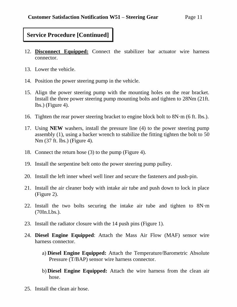
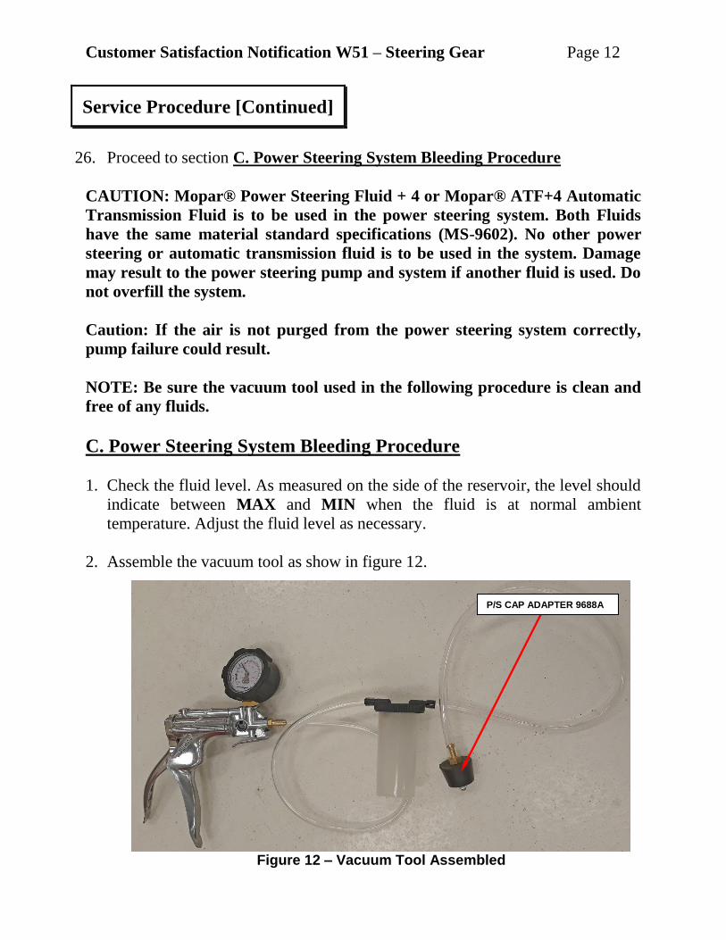
2. Assemble the vacuum tool as show in figure 12.
Service Procedure [Continued]
Figure 12 – Vacuum Tool Assembled
P/S CAP ADAPTER 9688A
Customer Satisfaction Notification W51 – Steering Gear Page 13
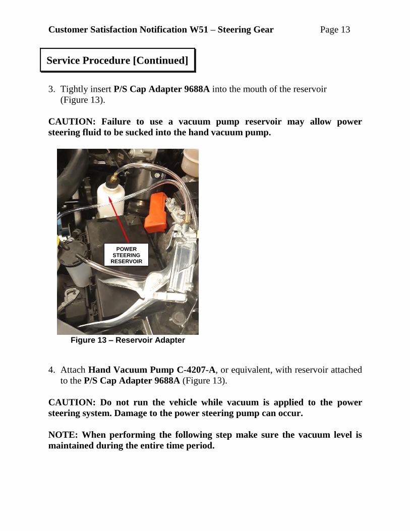
3. Tightly insert P/S Cap Adapter 9688A into the mouth of the reservoir
(Figure 13).
CAUTION: Failure to use a vacuum pump reservoir may allow power
steering fluid to be sucked into the hand vacuum pump.
4. Attach Hand Vacuum Pump C-4207-A, or equivalent, with reservoir attached
to the P/S Cap Adapter 9688A (Figure 13).
CAUTION: Do not run the vehicle while vacuum is applied to the power
steering system. Damage to the power steering pump can occur.
NOTE: When performing the following step make sure the vacuum level is
maintained during the entire time period.
Service Procedure [Continued]
Figure 13 – Reservoir Adapter
POWER STEERING
RESERVOIR
Customer Satisfaction Notification W51 – Steering Gear Page 14
5. Using Hand Vacuum Pump, apply 68-85 kPa (20-25 In. Hg) of vacuum to the
system for a minimum of three minutes.
6. Slowly release the vacuum and remove the special tools.
7. Adjust the fluid level as necessary. Refer to step one.
8. Repeat step one through step six until the fluid no longer drops when vacuum is
applied.
9. Install the negative battery cable(s) with IBS to the negative post and tighten to
7N·m (62In. Lbs.).
10. Connect the IBS wire harness connector.
11. Start the engine and cycle the steering wheel lock-to-lock three times.
NOTE: Do not hold the steering wheel at the stops.
12. Stop the engine and check for leaks at all connections.
13. Check for any signs of air in the reservoir and check the fluid level. If air is
present, repeat the procedure as necessary.
14. Perform the reset steering angle calibration.
a) Center the steering wheel and secure it in place
b) Connect the scan tool
c) Under Steering Assist Module (SAM), Routines, perform the Reset
Steering Angle Calibration
15. Perform the wheel alignment standard procedure (Set Toe).
16. Road test the vehicle.
17. Return the vehicle to the customer.
Service Procedure [Continued]
Customer Satisfaction Notification W51 – Steering Gear Page 15
Claims for vehicles that have been serviced must be submitted on the
DealerCONNECT Claim Entry Screen located on the Service tab. Claims paid
will be used by FCA to record Customer Satisfaction Notification service
completions and provide dealer payments.
Use the following labor operation number and time allowance:
Labor Operation Time
Number Allowance
Replace Hydraulic-Electric Steering Gear 19-W5-11-82 2.8 hours
NOTE: See the Warranty Administration Manual, Recall Claim Processing
Section, for complete claim processing instructions.
To view this notification on DealerCONNECT, select “Global Recall System” on
the Service tab, then click on the description of this notification.
All involved vehicle owners known to FCA are being notified of the service
requirement by mail. They are requested to schedule appointments for this service
with their dealers. A generic copy of the owner letter is attached.
Completion Reporting and Reimbursement
Dealer Notification
Owner Notification and Service Scheduling
Customer Satisfaction Notification W51 – Steering Gear Page 16
All involved vehicles have been entered into the DealerCONNECT Global Recall
System (GRS) and Vehicle Information Plus (VIP) for dealer inquiry as needed.
GRS provides involved dealers with an updated VIN list of their incomplete
vehicles. The owner’s name, address and phone number are listed if known.
Completed vehicles are removed from GRS within several days of repair claim
submission.
To use this system, click on the “Service” tab and then click on “Global Recall
System.” Your dealer’s VIN list for each recall displayed can be sorted by: those
vehicles that were unsold at campaign launch, those with a phone number, city, zip
code, or VIN sequence.
Dealers should perform this repair on all unsold vehicles before retail
delivery. Dealers should also use the VIN list to follow up with all owners to
schedule appointments for this repair.
VIN lists may contain confidential, restricted owner name and address information that was
obtained from the Department of Motor Vehicles of various states. Use of this information is
permitted for this notification only and is strictly prohibited from all other use.
If you have any questions or need assistance in completing this action, please
contact your Service and Parts District Manager.
Customer Service / Field Operations
FCA US LLC
Vehicle Lists, Global Recall System, VIP and Dealer Follow Up
Additional Information
This notice applies to your vehicle,
W51
YOUR SCHEDULING OPTIONS
1. RECOMMENDED OPTION
Call your authorized Chrysler /
Dodge / Jeep® / RAM Dealership
2. Call the FCA Recall Assistance
Center at 1-800-853-1403. An
agent can confirm part
availability and help schedule an
appointment
3. Visit recalls.mopar.com, scan the
QR code below, or download the
Mopar Owner’s Companion App.
Get access to recall notifications,
locate your nearest dealer, and more
through this website or Mopar
Owner’s Companion App. You will be
asked to provide your Vehicle
Identification Number (VIN) to
protect and verify your identity.
DEALERSHIP INSTRUCTIONS
Please reference CSN W51.
CUSTOMER SATISFACTION NOTIFICATION Steering Gear
Dear [Name],
At FCA US LLC, we recognize that the success of our business depends on the satisfaction of
our customers. We are constantly monitoring the quality of our products and looking for
opportunities to improve our vehicles even after they are sold. Because your long-term
satisfaction is important to us, we are contacting you on important improvements we would
like to make to your vehicle [1]. This will be done at no charge to you.
We are recommending the following improvements be performed on certain [2020 Model
Year (DJ) Ram 2500 Pickup, (D2) Ram 3500 Pickup] vehicles.
WHY DOES MY VEHICLE NEED REPAIRS?
The Hydraulic-Electric steering gear on your vehicle may have been manufactured with an
insufficient amount of grease. Lack of grease may cause a gritty or non-smooth feel in the
steering wheel when turning.
HOW DO I RESOLVE THIS CUSTOMER SATISFACTION NOTIFICATION?
FCA US will repair your vehicle free of charge (parts and labor). To do this, your dealer
will replace the steering gear. The estimated repair time is about 2 hours. In addition, your
dealer will require your vehicle for proper check-in, preparation, and check-out during your
visit, which may require more time. Your time is important to us, so we recommend that you
schedule a service appointment to minimize your inconvenience. Please bring this letter with
you to your dealership.
TO SCHEDULE YOUR FREE REPAIR,
CALL YOUR CHRYSLER, DODGE, JEEP OR RAM DEALER TODAY
WHAT IF I ALREADY PAID TO HAVE THIS REPAIR COMPLETED?
If you have already experienced this specific condition and have paid to have it repaired, you
may visit www.fcarecallreimbursement.com to submit your reimbursement request online. [2]
Once we receive and verify the required documents, reimbursement will be sent to you within
60 days. If you have had previous repairs performed and/or already received reimbursement,
you may still need to have the repair performed.
We apologize for any inconvenience, but are sincerely concerned about your satisfaction.
Thank you for your attention to this important matter.
Customer Assistance/Field Operations
FCA US LLC
VEHICLE PICTURE
LOGO
[Model Year and Model]
VIN XXXXXXXXXXXXXXXXX
QR Code
[1] If you no longer own this vehicle, please help us update our records. Call the FCA Recall Assistance Center at 1-800-853-1403 to update your information.
[2] You can also mail in your original receipts and proof of payment to the following address for reimbursement consideration: FCA Customer Assistance, P.O. Box 21-
8004, Auburn Hills, MI 48321-8007, Attention: Recall Reimbursement.
Mr. Mrs. Customer
1234 Main Street
Hometown, MI 48371