cutler-hammer i.b. ats-rm01 - eatonpub/@electrical/documents/content/...1.2.1 design configuration...
TRANSCRIPT

Effective June, 1999
I.B. ATS-RM01Cutler-Hammer
Instructions for Cutler-Hammer Residential Automatic Transfer Switch


Effective 6/99
I.B. ATS-RM01 Page iii
All possible contingencies which may arise during installation, operation or maintenance, and all details andvariations of this equipment do no purport to be covered by these instructions. If further information isdesired by purchaser regarding his particular installation, operation or maintenance of particular equipment,contact a Cutler-Hammer representative.
READ AND UNDERSTAND THE INSTRUCTIONSCONTAINED HEREINAFTER BEFORE ATTEMPTINGTO UNPACK, ASSEMBLE, OPERATE OR MAINTAINTHIS EQUIPMENT.
HAZARDOUS VOLTAGES ARE PRESENT INSIDETRANSFER SWITCH ENCLOSURES THAT CANCAUSE DEATH OR SEVERE PERSONAL INJURY.FOLLOW PROPER INSTALLATION, OPERATIONAND MAINTENANCE PROCEDURES TO AVOIDTHESE VOLTAGES.
WARNINGTRANSFER SWITCH EQUIPMENT COVERED BYTHIS INSTRUCTION BOOK IS DESIGNED AND TEST-ED TO OPERATE WITHIN ITS NAMEPLATE RAT-INGS. OPERATION OUTSIDE OF THESE RATINGSMAY CAUSE THE EQUIPMENT TO FAIL RESULTINGIN DEATH, SERIOUS BODILY INJURY AND/ORPROPERTY DAMAGE. ALL RESPONSIBLE PERSON-NEL SHOULD LOCATE THE DOOR MOUNTEDEQUIPMENT NAMEPLATE AND BE FAMILIAR WITHTHE INFORMATION PROVIDED ON THE NAME-PLATE. A TYPICAL EQUIPMENT NAMEPLATE ISSHOWN IN FIGURE 1.
Figure 1 Typical Automatic Transfer Switch Equipment Nameplate
Cutler-Hammer
Automatic Transfer Switch
ECat No: RTHMFDA20100WSU 9/95
GO No: 1/1
Item: 1
Poles: 2 Amps: 100 Volt: 240
Phase: 1 Hertz: 60 Wire: 3

Effective 6/99
I.B. ATS-RM01
TABLE OF CONTENTS
PageSECTION 1: INTRODUCTION
1.1 Preliminary Comments and Safety Precautions..................................................................................................11.1.1 Warranty and Liability Information..........................................................................................................11.1.2 Safety Precautions .................................................................................................................................1
1.2 General Information.............................................................................................................................................11.2.1 Design Configuration..............................................................................................................................2
1.3 Transfer Switch Catalog Number Identification ...................................................................................................2
SECTION 2: RECEIVING, HANDLING AND STORAGE
2.1 Receiving.............................................................................................................................................................42.2 Handling ..............................................................................................................................................................42.3 Storage ...............................................................................................................................................................4
SECTION 3: EQUIPMENT DESCRIPTION
3.1 Introduction..........................................................................................................................................................53.2 Options ...............................................................................................................................................................53.3 Standards ............................................................................................................................................................5
SECTION 4: INSTALLATION AND WIRING
4.1 General ...............................................................................................................................................................74.2 Mounting Location ...............................................................................................................................................74.3 Mounting Procedure ............................................................................................................................................84.4 Power Cable Connections ..................................................................................................................................94.5 Wiring ................................................................................................................................................................104.6 Installation .........................................................................................................................................................104.7 Engine Start Connection ...................................................................................................................................104.8 Preliminary Checks ...........................................................................................................................................10
SECTION 5: FUNCTIONAL TESTING
5.1 Preliminary Checks ...........................................................................................................................................135.2 Energize the Switch...........................................................................................................................................135.3 Operational Checks...........................................................................................................................................13
Page iv

Effective 6/99
I.B. ATS-RM01 Page v
PageSECTION 6: TESTING AND PROBLEM SOLVING
6.1 Plant Exerciser Timer ........................................................................................................................................146.1.1 Timer Programming..............................................................................................................................14
SECTION 7: MAINTENANCE
7.1 Introduction........................................................................................................................................................157.2 Procedures ........................................................................................................................................................15

Effective 6/99
I.B. ATS-RM01Page vi
LIST OF FIGURES
Figure Title Page
1-1 Typical Load Transfer Switch (circuit breaker type) Schematic.................................................................11-2 Typical Residential Automatic Transfer Switch..........................................................................................3
4-1 Dimensions and Plan View of Residential Automatic Transfer Switch (30 -100A) ....................................74-2 Dimensions and Plan View of Residential Automatic Transfer Switch (150 -200A) ..................................74-3 Cover Removal .........................................................................................................................................84-4 Deadfront Removal ...................................................................................................................................94-5 Cable Connections ....................................................................................................................................94-6 Typical installation of a residential or light duty automatic transfer switch ..............................................114-7 Typical installation of a residential or light duty automatic transfer switch ..............................................114-8 Diagram of Typical Installation (Critical Loads Only) ..............................................................................124-9 Diagram of Typical Installation (All Household Loads) ...........................................................................12
7-1 Wiring Diagram for Residential Automatic Transfer Switch ....................................................................16
LIST OF TABLES
Table Title Page
1.1 Transfer Switch Catalog Number Explanation...........................................................................................2
4.1 Wire Size for Automatic Transfer Switch ...................................................................................................9
7.1 Periodic Maintenance Procedures...........................................................................................................17
Page 1
SECTION 1: INTRODUCTION
1.1 PRELIMINARY COMMENTS AND SAFETYPRECAUTIONS
This technical document is intended to cover mostaspects associated with the installation, application,operation and maintenance of the Residential AutomaticTransfer Switch. It is provided as a guide for authorizedand qualified personnel only. Please refer to the specificWARNING and CAUTION in Section 1.1.2 before pro-ceeding. If further information is required by the pur-chaser regarding a particular installation, application ormaintenance activity, a Cutler-Hammer representativeshould be contacted.
1.1.1 WARRANTY AND LIABILITY INFORMATION
No warranties, expressed or implied, including war-ranties of fitness for a particular purpose of merchant-ability, or warranties arising from course of dealing orusage of trade, are made regarding the information, rec-ommendations and descriptions contained herein. In noevent will Cutler-Hammer be responsible to the purchas-er or user in contract, in tort (including negligence), strictliability or otherwise for any special, indirect, incidentalor consequential damage or loss whatsoever, includingbut not limited to damage or loss of use of equipment,plant or power system, cost of capital, loss of power,additional expenses in the use of existing power facili-ties, or claims against the purchaser or user by its cus-tomers resulting from the use of the information anddescriptions contained herein.
1.1.2 SAFETY PRECAUTIONS
All safety codes, safety standards and/or regulationsmust be strictly observed in the installation, operationand maintenance of this device.
THE WARNINGS AND CAUTIONS INCLUDED ASPART OF THE PROCEDURAL STEPS IN THIS DOCU-MENT ARE FOR PERSONNEL SAFETY AND PRO-TECTION OF EQUIPMENT FROM DAMAGE. ANEXAMPLE OF A TYPICAL WARNING LABEL HEAD-ING IS SHOWN ABOVE TO FAMILIARIZE PERSON-NEL WITH THE STYLE OF PRESENTATION. THISWILL HELP TO INSURE THAT PERSONNEL AREALERT TO WARNINGS, WHICH APPEAR THROUGH-OUT THE DOCUMENT. IN ADDITION, CAUTIONSARE ALL UPPER CASE AND BOLDFACE.
COMPLETELY READ AND UNDERSTAND THE MATE-RIAL PRESENTED IN THIS DOCUMENT BEFOREATTEMPTING INSTALLATION, OPERATION ORAPPLICATION OF THE EQUIPMENT. IN ADDITION,ONLY QUALIFIED PERSONS SHOULD BE PERMIT-TED TO PERFORM ANY WORK ASSOCIATED WITHTHE EQUIPMENT. ANY WIRING INSTRUCTIONS PRE-SENTED IN THIS DOCUMENT MUST BE FOLLOWEDPRECISELY. FAILURE TO DO SO COULD CAUSEPERMANENT EQUIPMENT DAMAGE.
1.2 GENERAL INFORMATION
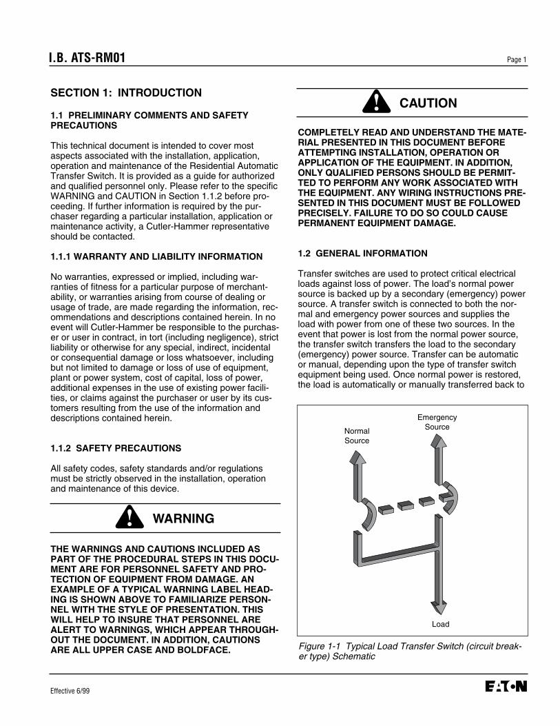
Transfer switches are used to protect critical electricalloads against loss of power. The load’s normal powersource is backed up by a secondary (emergency) powersource. A transfer switch is connected to both the nor-mal and emergency power sources and supplies theload with power from one of these two sources. In theevent that power is lost from the normal power source,the transfer switch transfers the load to the secondary(emergency) power source. Transfer can be automaticor manual, depending upon the type of transfer switchequipment being used. Once normal power is restored,the load is automatically or manually transferred back to
I.B. ATS-RM01
Effective 6/99
WARNING
CAUTION
Figure 1-1 Typical Load Transfer Switch (circuit break-er type) Schematic
NormalSource
EmergencySource
Load
Page 2
the normal power source, again depending upon thetype of transfer equipment being used (Figure 1-1).
In automatic transfer switch equipment, the switch’sintelligence system initiates the transfer when normalpower fails or falls below a preset voltage. If the emer-gency power source is a standby generator, the transferswitch initiates generator starting and transfers to theemergency power source when sufficient generator volt-age is available. When normal power is restored, thetransfer switch automatically transfers back and initiatesengine shutdown. In the event the normal power sourcefails and the emergency power source does not appear,the automatic transfer switch remains connected to thenormal power source until the emergency power sourcedoes appear. Conversely, if connected to the emer-gency power source and the emergency power sourcefails while the normal power source is still unavailable,the automatic transfer switch remains connected to theemergency power source.
Automatic transfer switches automatically perform thetransfer function, and include three basic elements:
(1) Main contacts to connect and disconnect the loadto and from the source of power.
(2) A mechanism to make the transfer of the main con-tacts from source to source.
(3) Intelligence/supervisory circuits to constantly moni-tor the condition of the power sources and thus pro-vide the intelligence necessary for the switch andrelated circuit operation.
1.2.1 DESIGN CONFIGURATION
The Cutler-Hammer transfer switch is a rugged, com-pact design that utilizes molded case switches to trans-fer essential loads from one power source to another(Figure 1-2). Molded case switches are interlocked toprevent both switches from being closed at the sametime.
1.3 TRANSFER SWITCH CATALOG NUMBER IDENTIFICATION
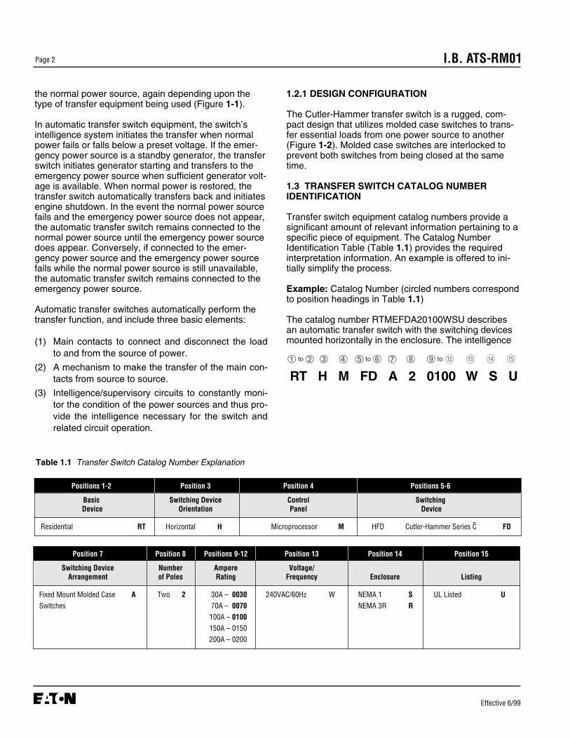
Transfer switch equipment catalog numbers provide asignificant amount of relevant information pertaining to aspecific piece of equipment. The Catalog NumberIdentification Table (Table 1.1) provides the requiredinterpretation information. An example is offered to ini-tially simplify the process.
Example: Catalog Number (circled numbers correspondto position headings in Table 1.1)
The catalog number RTMEFDA20100WSU describesan automatic transfer switch with the switching devicesmounted horizontally in the enclosure. The intelligence
I.B. ATS-RM01
Effective 6/99
Positions 1-2 Position 3 Position 4 Positions 5-6
Basic Switching Device Control SwitchingDevice Orientation Panel Device
Residential RT Horizontal H Microprocessor M HFD Cutler-Hammer Series C FD
Position 7 Position 8 Positions 9-12 Position 13 Position 14 Position 15
Switching Device Number Ampere Voltage/Arrangement of Poles Rating Frequency Enclosure Listing
Fixed Mount Molded Case A Two 2 30A – 0030 240VAC/60Hz W NEMA 1 S UL Listed USwitches 70A – 0070 NEMA 3R R
100A – 0100150A – 0150200A – 0200
Table 1.1 Transfer Switch Catalog Number Explanation
➀ to ➁ ➂ ➃ ➄ to ➅ ➆ ➇ ➈ to ➉
RT H M FD A 2 0100 W S U12 13 14 15

Effective 6/99
I.B. ATS-RM01 Page 3
represented by the control panel is electromechanicallogic. The frame is for 100 amp service, and the switchis a 2-pole, fixed mount molded case switch. The contin-uous current rating of this equipment is 100 amperesand applicable at 240 VAC, 60Hz. The transfer switchequipment is enclosed in a NEMA 1 enclosure and list-ed for UL applications.
Figure 1-2 Typical Residential Automatic TransferSwitch (30-100A)

Effective 6/99
I.B. ATS-RM01Page 4
SECTION 2: RECEIVING, HANDLING, ANDSTORAGE
2.1 RECEIVING
Every effort is made to ensure that the transfer switchequipment arrives at its destination undamaged andready for installation. Packing is designed to protectinternal components as well as the enclosure. Careshould be exercised, however, to protect the equipmentfrom impact at all times. Do not remove protective pack-aging until the equipment is ready for installation .
When transfer switch equipment reaches its destination,the customer should inspect the shipping container forany obvious signs of rough handling and/ or externaldamage that occurred during transportation. Record anyexternal and internal damage for reporting to the trans-portation carrier and Cutler-Hammer, once a thoroughinspection is complete. All claims should be as specificas possible and include Shop Order and General Ordernumbers.
A shipping label affixed to the shipping containerincludes a variety of equipment and customer informa-tion, such as General Order number and CustomerNumber. Make certain that this information matchesother shipping paper information.
Each transfer switch enclosure is packaged in its ownbox. Heavy duty cardboard sides surround the enclo-sure and are further supported with reinforced card-board corner posts. A heavy duty cardboard lid coversthe entire opening. Do not discard the packing materialuntil the equipment is ready for installation.
Once the top packaging is removed from the shipment,the enclosure door can be opened. A plastic bag of doc-uments will be found in the enclosure, usually attachedto the inside of the door. Important documents, such astest reports, wiring diagrams, appropriate instructionleaflets and a warranty registration card, are enclosedwithin the bag and should be filed in a safe place.
2.2 HANDLING
As previously mentioned, transfer switch equipment ispackaged in its own box. Protect the equipment fromimpact at all times and do not double stack. Once theequipment is in the installation location and ready to beinstalled, packaging material can be removed. Refer toSection 4 of this manual for specific installation instruc-tions.
2.3 STORAGE
Although well packaged, this equipment is not suitablefor storage outdoors. The equipment warranty will notbe applicable if there is evidence of outdoor storage. Ifthe equipment is to be stored indoors for any period oftime, it should be stored with its protective packagingmaterial in place. Protect the equipment at all times fromexcessive moisture, construction dirt, corrosive condi-tions, and other contaminants. It is strongly suggestedthat the package-protected equipment be stored in a cli-mate-controlled environment of -20°C to 65°C with a rel-ative humidity of 80 percent or less. Do not under anycircumstance, stack other equipment on top of a transferswitch equipment enclosure, whether packaged or not.

Effective 6/99
I.B. ATS-RM01 Page 5
SECTION 3: EQUIPMENT DESCRIPTION
3.1 INTRODUCTION
The Cutler-Hammer Residential Automatic TransferSwitch is assembled and tested at the factory. It isdesigned to be used in conjunction with standby powerdistribution equipment to provide an alternate source ofpower to critical circuits in the event that a primarypower source is interrupted.
This switch monitors both normal and standby powersources and automatically transfers critical load circuitsbetween the two sources depending upon which sourceis available. The normal source is preferred and willremain connected to the switch if it is available.
3.2 OPTIONS
The following section describes the standard features inthe RTHM Transfer Switch. The time delays are notadjustable.
1. Time Delay Normal to Emergency (TDNE)This feature delays the transfer from the normal powersource to the emergency power source in order to over-ride momentary normal power source outages and/orfluctuations. Timing begins when the emergency powersource becomes available. It does not affect initiation ofthe engine start circuit. Should the normal power sourcefail, the engine start contact will close and, if connectedto an engine generator, will initiate an engine start-up in10 seconds. The TDNE timer is set for three seconds.
2. Time Delay on Engine Starting (TDES)This feature is used only where the emergency powersource is an engine generator. It delays initiation of theengine start circuit in order to override momentary nor-mal power source outages and/or fluctuations. It doesnot affect the ability of the transfer switch to transferfrom the normal power source to the emergency powersource. The TDES timer is set for 10 seconds.
3. Time Delay Emergency to Normal (TDEN)This feature delays transfer from the emergency powersource to the normal power source to allow the normalpower source to stabilize before the transfer is initiated.Timing begins when the normal source becomes avail-able. If the emergency power source fails during timing,the time delay is overridden and an immediate transferto the normal power source will occur. The TDEN timeris set for 10 seconds.
3.3 STANDARDS
Cutler-Hammer transfer switch equipment enclosed in aNEMA 1 enclosure is listed for application by UL andUL-C. In addition, Cutler-Hammer automatic transferswitches are listed in File E38116 by UnderwritersLaboratories, Inc. under Standard UL 1008. This stan-dard covers requirements for automatic transfer switch-es intended for use in ordinary locations to provide light-ing and power as follows:
a. In emergency systems, in accordance with articles517 and 700 in the National Electrical Code,ANSI/NFPA 70 and the National Fire ProtectionAssociation No. 76A and/or
b. In standby systems, in accordance with article 702of the National Electrical Code and/or
c. In legally required standby systems in accordancewith article 701 of the National Electrical Code.
Cutler-Hammer automatic transfer switches are avail-able to meet NFPA110 for emergency and standbypower systems, and NFPA99 for health care facilitieswhen ordered with the appropriate options.
4. Time Delay Engine Cool-Off This feature allows the engine generator to run after thetransfer switch returns to the normal power source with-out load. The TDEC timer is set for 5 minutes.
5D. Undervoltage Sensing for Emergency SourceThis feature enables the logic to constantly monitor theemergency power source. The logic prevents transferfrom the normal power source to the emergency sourceuntil the emergency power source has reached anacceptable operating voltage. Drop-out is set at 70% ofnominal voltage and pick-up is set at 80% of nominalvoltage.
23. Plant ExerciserThis feature is a 7-day timer and provides automatictesting of the emergency source once each week, 15minutes under load and 5 minutes no load.
26. Undervoltage Sensing for Normal SourceThis feature enables the logic to constantly monitor thenormal power source. The logic prevents transfer fromthe emergency power source to the normal source untilthe normal power source has reached an acceptableoperating voltage. Drop-out is set at 70% of nominal

Effective 6/99
I.B. ATS-RM01Page 6
Since Cutler-Hammer automatic transfer switches usespecially designed molded case switches as the mainpower switching contacts, these devices must also belisted under the additional UL Standard 1087.Underwriters laboratories uses two basic types of listingprograms — label service and re-examination.
UL1087 employ a label service listing program whichrequires an extensive follow-up testing program for list-ed devices. Standard UL1008 for automatic transferswitches lists devices under the reexamination programwhich only requires a continual physical reexaminationof the components used in the product to ensure consis-tency with the originally submitted device. Follow-uptesting is not required by UL1008.
Representative production samples of molded caseswitches and molded case circuit breakers used inCutler-Hammer automatic transfer switches are subject-ed to a complete test program identical to the originallysubmitted devices on an ongoing periodic basis perUL1087. The frequency of such a re-submittal can be asoften as every quarter for a low ampere device. Any fail-ure during one of these periodic re-submittals couldresult in a loss of the valued UL listing mark.

Effective 6/99
I.B. ATS-RM01 Page 7
SECTION 4: INSTALLATION AND WIRING
4.1 GENERAL
Transfer switches are factory wired and tested.Installation requires solidly mounting the enclosed unitand connecting power cables and auxiliary pilot circuits.Physical mounting procedures and power cable connec-tions are covered in this section. Once a transfer switchis properly installed and wired, it should be mechanicallyand electrically checked for proper installation and oper-ation. The procedures for these initial mechanical andelectrical checks are outlined in Section 5 of this instruc-tion manual.
4.2 MOUNTING LOCATION
Choose a location that offers a flat, rigid mounting sur-face capable of supporting the weight of the enclosedtransfer switch equipment (Figure 4-1, 30-100A orFigure 4-2, 150-200A). Avoid locations that are moist,hot, or dusty, however, there are enclosure designsavailable for special environments. If there are anydoubts as to location suitability, discuss it with yourCutler-Hammer representative.
Check to make certain that there are no pipes, wires, orother mounting hazards in the immediate mounting areathat could create a problem.
Figure 4-1 Dimensions and Plan View of ResidentialAutomatic Transfer Switch (in) (30-100A)
Figure 4-2 Dimensions and Plan View of ResidentialAutomatic Transfer Switch (in) (150-200A)
Weight 45lbs. (21kg.)
Weight 65lbs. (30kg.)
16.0020.00
2.05
4.33
11.00
18.22
20.00
18.22
8.00
Back View ShowingWall Mounting Dimensions
Back View ShowingWall Mounting Dimensions
16.00
15.00
5.21
2.05
28.22
20.00
8.00

Effective 6/99
I.B. ATS-RM01Page 8
Carefully remove all packing material from the transferswitch at the mounting location. Do not discard the TopCardboard Pad. It is used as a template for locating themounting holes. Even though an equipment inspectionwas made when the equipment was received, makeanother careful inspection of the enclosure and theenclosed transfer switch as packing material is removedand the enclosure readied for mounting. Be especiallyalert for distorted metal, loose wires or damaged components.
4.3 MOUNTING PROCEDURE
EXTREME CARE SHOULD BE TAKEN TO PROTECTTHE TRANSFER SWITCH FROM DRILL CHIPS, FIL-INGS AND OTHER CONTAMINANTS WHEN MAKINGTHE CABLE ENTRY HOLES AND MOUNTING THEENCLOSURE TO PREVENT COMPONENT DAMAGEOR A FUTURE MALFUNCTION .
The installation must comply fully with all applicablecodes, standards and regulations.
With the enclosed transfer switch equipment unpackedand ready for mounting, proceed with these steps:
CAUTION
NOTICE
Step 1: Remove the 4 cover screws and place the cover in a safe place (Figure 4-3).
Step 2: Before removing the 4 screws that hold the top Dead Front cover in place, disconnect the 5 white plugs on the logic board. Care should betaken when it is placed aside. Remove the 4 screws from the bottom Dead Front and place it in a safe place (Figure 4-4).
Step 3: Depending upon customer preference and Transfer Switch location, the knockouts may be used or additional holes may be drilled for cable entry and control wiring.
For control wiring (Generator start wiring), thesewires must be isolated from both power sourcecables.
Step 4: Mount the switch to a rigid structure as close to the electrical loads as possible. Use the cardboard template provided to mark the mounting pattern, and start the mounting hardware sev-eral turns into the mounting structure. Lift the switch over the embossed teardrop mounting holes and secure the mounting screws.
Step 5: Connect cables as follows (Figure 4-5):
• NORMAL (utility) power cables to terminals N1, N2.
• EMERGENCY (generator) power cables to E1, E2.
• Customer load cables to T1, T2.• NEUTRAL cable to Neutral terminal.• GROUND wire to green 1/4-20 bolt.
Step 6: Generator start terminals are red and numbered51, 52. They are located in the lower right handcorner of the power panel, and used when the generator has an automatic start feature.
Step 7: Tighten all cables and wiring to the specifictionson the labeling within the switch.
NOTICE
Figure 4-3 Cover Removal
4 Screws

Effective 6/99
I.B. ATS-RM01 Page 9
4.4 POWER CABLE CONNECTIONS
POWER CONDUCTORS MAY HAVE VOLTAGE PRE-SENT THAT CAN CAUSE SEVERE PERSONALINJURY OR DEATH. DE-ENERGIZE ALL POWER ORCONTROL CIRCUIT CONDUCTORS TO BE CON-NECTED TO THE TRANSFER SWITCH EQUIPMENTBEFORE BEGINNING TO WORK WITH THE CON-DUCTORS AND/OR TERMINATING THEM TO THEEQUIPMENT.
USE OF CABLE LUGS, NOT DESIGNED FOR THETRANSFER SWITCH MAY CAUSE HEATING PROB-LEMS. BREAKER LUGS ONLY MOUNT TO THEBREAKER, WHILE TRANSFER SWITCH LUGSMOUNT TO BOTH THE BREAKER AND THE BUS-BAR BEHIND THE BREAKER. FOR INSTALLATIONINSTRUCTIONS, REFER TO THE INSTRUCTIONLEAFLET SUPPLIED FOR THE SPECIFIC LUGS.
TO HELP PREVENT COMPONENT DAMAGE ORFUTURE MALFUNCTIONS, USE EXTREME CARE TOKEEP CONTAMINANTS OUT OF THE TRANSFERSWITCH EQUIPMENT WHEN MAKING POWERCABLE CONNECTIONS.
Test all power cables prior to connection to the unit toensure that conductors or cable insulation has not beendamaged while being pulled into position.
Power cables are to be connected to solderless screwtype lugs located on the transfer switch switchingdevices. Verify that the lugs supplied will accommodatethe power cables being used. Also verify that the cablescomply with local electrical codes. Standard transferswitch equipment, as supplied from the factory, willaccommodate the wire sizes shown in Table 4.1.
Carefully strip insulation from the power cables to avoidnicking or ringing of the conductor strands. Prepare thestripped conductor termination end by cleaning it with awire brush. If aluminum conductors are used, apply anappropriate joint compound to the clean conductor sur-face area.
WARNING
Transfer Switch Number ofAmp Rating Wire Size Range Cables per Phase
30 - 150 #14 - 3/0 1
200 #6-300MCM 1
Table 4.1 Wire Size for Automatic Transfer Switch
CAUTION
CAUTION
Figure 4-4 Deadfront Removal Figure 4-5 Cable Connections
Ground Screw 51 52Neutral
E1 E2 N1 N2
T1 T2

Page 10 I.B. ATS-RM01
Effective 6/99
IMPROPER POWER CABLE CONNECTIONS CANCAUSE EXCESSIVE HEAT AND SUBSEQUENTEQUIPMENT FAILURE.
Tighten cable lugs to the torque identified on the labelaffixed to the unit immediately adjacent to the lugs.
4.5 WIRING
POWER CONDUCTORS AND CONTROL WIRINGMAY HAVE VOLTAGE PRESENT THAT CAN CAUSESEVERE PERSONAL INJURY OR DEATH. DE-ENER-GIZE ALL POWER OR CONTROL CIRCUIT CONDUC-TORS BEFORE BEGINNING TO PERFORM ANYWIRING ACTIVITY TO OR WITHIN THE TRANSFERSWITCH EQUIPMENT.
CHECK THE TRANSFER SWITCH EQUIPMENTNAMEPLATE FOR RATED VOLTAGE. IT SHOULDBE THE SAME AS THE NORMAL AND EMERGENCYLINE VOLTAGES. OPERATING THE EQUIPMENT ONIMPROPER VOLTAGE CAN CAUSE EQUIPMENTDAMAGE.
4.6 INSTALLATION
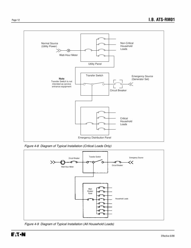
In a typical installation for critical loads (Figure 4-6), theautomatic transfer switch (ATS) (1) and the generator (2)are connected to the residential power supply. The ATS(1) and emergency distribution panel (3) receive normalpower from a dedicated breaker in the utility service panel(4). The ATS and emergency panel receive emergencypower from the generator (2). Power from the utility feedsthe utility panel.
When normal power fails, the ATS will sense the failure,start the generator, and switch all loads to the emergencypanel. All emergency loads will receive power from the
generator. A line breaker is required between the emer-gency source (generator) and the transfer switch (Figure4-8). When normal power returns, the ATS will switch allpower back to the utility and shut down the generator.
In addition, another typical installation for householdloads can be considered (Figure 4-7). Refer to Figure 4-9 for a household loads connection diagram.
4.7 ENGINE START CONNECTION
The engine control contact connections are located onthe lower right of the intelligence portion of the ATS.NOTE: Prior to making the engine start connection tothe switch, set the engine generator controls selectorswitch in the OFF position to prevent an unwantedengine start. Connect the engine start wires to the redterminal blocks marked 51 and 52. A contact closesbetween these terminal blocks when an engine start sig-nal is provided by the ATS logic. The wiring diagram(Figure 7-1) provides additional engine start connectioninformation.
4.8 PRELIMINARY CHECKS
After the ATS enclosure is installed and power cablesare connected to the equipment, thoroughly inspect theunit to ensure that no tools were left inside and that thecabinet is free of debris. If necessary, use a vacuumcleaner to remove any and all construction or installationdebris from the equipment.
Read and understand all labels on the equipment.Review and understand the wiring diagrams suppliedwith the equipment. Note any optional accessories thatmay have been furnished with this unit and review theiroperation.
Verify that the phase-to-phase line voltages of both thenormal and emergency power sources are the sameand that they match rated voltage as indicated on theATS ratings label.
SEVERE EQUIPMENT DAMAGE CAN RESULT IFUNIT IS NOT APPLIED AT PROPER VOLTAGE.DO NOT ENERGIZE EQUIPMENT IF SUPPLY VOLT-AGES DO NOT MATCH EQUIPMENT RATINGSLABEL. CONTACT THE FACTORY FOR INSTRUC-TIONS TO MODIFY THE VOLTAGE RATING IN THEFIELD.
CAUTION
CAUTION
CAUTION
WARNING

Page 11I.B. ATS-RM01
Effective 6/99
Figure 4-6 Typical installation of a residential or light duty automatic transfer switch. The switch (1) and generator (2)are connected to the power supply. The automatic transfer switch is located between the emergency distribution (3)and the utility panel (4).
Figure 4-7 Typical installation of a residential or light duty automatic transfer switch. The switch (1) and generator (2)are connected to the power supply. The automatic transfer switch is located between the utility and the householdloads.
➀
➁
MainBreakerPanel
Transfer Switch
DisconnectSwitchor Fuse
WattHour-Meter
Generator
Page 12 I.B. ATS-RM01
Effective 6/99
Figure 4-8 Diagram of Typical Installation (Critical Loads Only)
Figure 4-9 Diagram of Typical Installation (All Household Loads)
Transfer Switch
Circuit BreakerWatt-Hour Meter
Circuit Breaker
MainBreakerPanel
Emergency Source
Household Loads
Page 13I.B. ATS-RM01
Effective 6/99
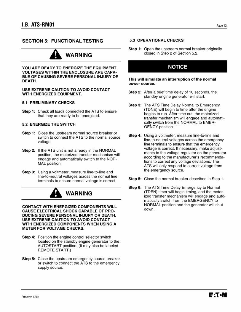
5.3 OPERATIONAL CHECKS
Step 1: Open the upstream normal breaker originallyclosed in Step 2 of Section 5.2.
This will simulate an interruption of the normalpower source.
Step 2: After a brief time delay of 10 seconds, thestandby engine generator will start.
Step 3: The ATS Time Delay Normal to Emergency(TDNE) will begin to time after the enginebegins to run. After time out, the motorizedtransfer mechanism will engage and automati-cally switch from the NORMAL to EMER-GENCY position.
Step 4: Using a voltmeter, measure line-to-line andline-to-neutral voltages across the emergencyline terminals to ensure that the emergencyvoltage is correct. If necessary, make adjust-ments to the voltage regulator on the generatoraccording to the manufacturer’s recommenda-tions to correct any voltage deviations. TheATS will only respond to correct voltage fromthe emergency source.
Step 5: Close the normal breaker described in Step 1.
Step 6: The ATS Time Delay Emergency to Normal(TDEN) timer will begin timing, and the motor-ized transfer mechanism will engage and auto-matically switch from the EMERGENCY toNORMAL position and the generator will shutdown.
SECTION 5: FUNCTIONAL TESTING
YOU ARE READY TO ENERGIZE THE EQUIPMENT.VOLTAGES WITHIN THE ENCLOSURE ARE CAPA-BLE OF CAUSING SEVERE PERSONAL INJURY ORDEATH.
USE EXTREME CAUTION TO AVOID CONTACTWITH ENERGIZED EQUIPMENT.
5.1 PRELIMINARY CHECKS
Step 1: Check all loads connected the ATS to ensurethat they are ready to be energized.
5.2 ENERGIZE THE SWITCH
Step 1: Close the upstream normal source breaker orswitch to connect the ATS to the normal sourcevoltage.
Step 2: If the ATS unit is not already in the NORMALposition, the motorized transfer mechanism willengage and automatically switch to the NOR-MAL position.
Step 3: Using a voltmeter, measure line-to-line andline-to-neutral voltages across the normal lineterminals to ensure normal voltage is correct.
CONTACT WITH ENERGIZED COMPONENTS WILLCAUSE ELECTRICAL SHOCK CAPABLE OF PRO-DUCING SEVERE PERSONAL INJURY OR DEATH.USE EXTREME CAUTION TO AVOID CONTACTWITH ENERGIZED COMPONENTS WHEN USING AMETER FOR VOLTAGE CHECKS.
Step 4: Position the engine control selector switchlocated on the standby engine generator to theAUTOSTART position. (It may also be labeledREMOTE START.)
Step 5: Close the upstream emergency source breakeror switch to connect the ATS to the emergencysupply source.
NOTICE
WARNING
WARNING

Page 14 I.B. ATS-RM01
Effective 6/99
SECTION 6: ADJUSTMENTS
6.1 PLANT EXERCISER TIMER
Option 23, described in Section 3.5, is a plant exerciser.The plant exerciser is a once every 7-day timer switchused to exercise the engine driven generator.
6.1.1 TIMER PROGRAMMING
Depress the PE Switch located on the end of the printedcircuit board for 2 seconds and release. Both Normaland Emergency LEDs will flash twice indicating the plantexerciser is now programmed correctly. The transferswitch will initiate a test now and every seven days fromthis time forward. If for some reason both power sourcesare unavailable for longer than 20 seconds, the plantexerciser will have to be reprogrammed when eitherpower source becomes available. To cancel the plantexerciser, depress the PE Switch for 4 seconds andrelease. Both Normal and Emergency LEDs will flash 4times to indicate the plant exerciser is now disabled.After the current exercise is complete the TransferSwitch will transfer back to Normal. The plant exerciserwill now have to be reprogrammed in order to exercisethe generator.
Page 15I.B. ATS-RM01
Effective 6/99
SECTION 7: MAINTENANCE
7.1 INTRODUCTION
HIGH VOLTAGES ARE PRESENT IN AND AROUNDTRANSFER SWITCH EQUIPMENT. BEFOREINSPECTING OR MAINTAINING THIS EQUIPMENT,DISCONNECT LINE POWER FROM THE EQUIPMENTBEING SERVICED BY OPENING AND LOCKINGOUT, IF POSSIBLE, THE NEXT HIGHEST DISCON-NECT DEVICE. FAILURE TO FOLLOW THIS PROCE-DURE COULD CAUSE PERSONAL INJURY AND/ORDEATH.
In general, transfer switch equipment is designed to berelatively maintenance free under normal usage.However, because of the variability of application condi-tions and the importance placed on dependable opera-tion by this type of equipment, inspection and mainte-
nance checks should be made on a regularly scheduledbasis. Since equipment maintenance will consist mainlyof keeping the equipment clean, the frequency of main-tenance will depend, to a large extent, on the cleanli-ness of the surroundings. If a significant amount of dustor foreign matter is present, a more frequent mainte-nance schedule should be followed.
It is suggested that visual inspections of the equipmentbe made on a regular basis, not just during regularlyscheduled periods. Always be alert for an accumulationof dirt in and around the structure, loose parts and/orhardware, cracks and/or discoloration to insulation, anddamaged or discolored components.
Figures 7-1 is the wiring diagram for the residentialautomatic transfer switch. Only qualified and experi-enced personnel should attempt any diagnostic workusing this diagram.
7.2 PROCEDURES
A suggested maintenance procedure to follow is out-lined in Table 7.1.
WARNING

Page 16 I.B. ATS-RM01
Effective 6/99
Figure 7-1 Wiring Diagram for Residential Automatic Transfer Switch

Page 17I.B. ATS-RM01
Effective 6/99
Table 7.1 Periodic Maintenance Procedures
a. Make transfer switch equipment safe for Disconnect line power from equipment being serviced by inspection and/or maintenance. opening next highest disconnect device. Make certain that
any accessory control power is switched off.
b. Inspect structure area for safety hazards or Inspect area, especially where molded case switching potential maintenance problems. devices are installed, for any safety hazards, including
personnel safety and fire hazards. Exposure to certain chemical vapors can cause deterioration of electrical connections.
Inspect for accumulated dirt, loose hardware or physical damage.
Examine primary insulation for evidence of cracking or overheating. Overheating will show as discoloration, melting, or blistering of conductor insulation, or as pitting or melting of conductor surfaces due to arcing.
Inspect secondary control connections for damage, and control wiring for insulation integrity.
c. Inspect molded case switching devices for dust, Remove dust, dirt, soot, grease, moisture and corrosion dirt, soot, grease, moisture or corrosion. contamination from the surface of the switching device
using a dry soft lint-free cloth, dry soft bristle brush and vacuum cleaner. Do not blow debris into circuit breaker or nearby breaker structure. If contamination is found, look for the source and fix the problem.
d. Check for material integrity, uneven wear, Severe material cracking will require replacement anddiscoloration or loose hardware. loose hardware will need to be tightened.
e. Check terminals and connectors for looseness Overheating will show as discoloration, melting, oror signs of overheating. blistering of conductor insulation.
Connections that do not have signs of looseness or overheating should not be disturbed.
f. Exercise the molded case switching devices If a switching device is used for frequent switching during if they are not often exercised while in normal operation, this step can be disregarded.operation. This will permit wiping action by the contacts.
g. Return transfer switch equipment to service. Make certain all barriers are in place and doors closed.Re-apply secondary and primary power.
Step Action

I.B. ATS-RM01
Cutler-HammerMoon Township, Pennsylvania U.S.A.
Effective 6/99 (ISI)Style 5724B30H01Printed in U.S.A.
This instruction booklet is published solely for informa-tion purposes and should not be considered all inclu-sive. If further information is required, you should con-sult Cutler-Hammer.
Sale of product shown in this literature is subject toterms and conditions outlined in appropriate Cutler-Hammer selling policies or other contractual agreementbetween the parties. This literature is not intended toand does not enlarge or add to any such contract. Thesole source governing the rights and remedies of anypurchaser of this equipment is the contract between thepurchaser and Cutler-Hammer.
NO WARRANTIES, EXPRESSED OR IMPLIED,INCLUDING WARRANTIES OF FITNESS FOR A PAR-TICULAR PURPOSE OR MERCHANTABILITY, ORWARRANTIES ARISING FROM COURSE OF DEAL-ING OR USAGE OF TRADE, ARE MADE REGARDINGTHE INFORMATION, RECOMMENDATIONS ANDDESCRIPTIONS CONTAINED HEREIN. In no eventwill Cutler-Hammer be responsible to the purchaser oruser in contract, in tort (including negligence), strict lia-bility or otherwise for any special, indirect, incidental orconsequential damage or loss whatsoever, including butnot limited to damage or loss of use of equipment, plantor power system, cost of capital, loss of power, addition-al expenses in the use of existing power facilities, orclaims against the purchaser or user by its customersresulting from the use of the information, recommenda-tions and description contained herein.