cutter soil mixing multi-axis soil mixing deep soil mixing ... · pdf filemounted on a large...
TRANSCRIPT
www.malcolmdrilling.com
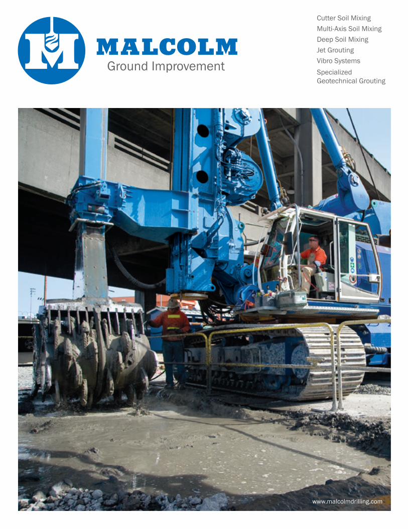
Ground Improvement
Cutter Soil Mixing Multi-Axis Soil MixingDeep Soil Mixing Jet GroutingVibro SystemsSpecialized Geotechnical Grouting

Ground improvement techniques complement and at times replace conventional methods when constructing foundation elements or shoring systems. Malcolm offers a full array of ground improvement techniques to modify and enhance the existing ground in situ through densification, solidification, reinforcement and drainage.
Ground Improvement
MALCOLM DRILLING COMPANYMalcolm Drilling Company was founded in 1962 by John Malcolm. Since then, the company has expanded throughout the United States with a network of full service district offices and shops that are able to service your construction project locally, effectively, and on schedule. As an independent, family-owned business, Malcolm is able to reinvest its capital in specialty equipment, allowing us to stay at the forefront of the industry and giving us the ability to offer a wide range of techniques for your project. Wherever your site is, and no matter how difficult the challenges are, Malcolm will provide you with the best engineered ground improvement solution for your project, at a competitive price.
SELECTION OF GROUND IMPROVEMENT Malcolm works closely with engineers, contractors, architects and owners to select and optimize the right ground improvement technique. Whether the challenge is liquefaction, lateral spreading, slope stability, static settlement, bearing capacity, support of excavation, tunneling through soft ground, or environmental remediation, Malcolm has the right ground improvement solution for each situation.
Multi-Axis Soil Mixing, San Francisco, CA
Cutter Soil Mixing Multi-Axis Soil MixingDeep Soil Mixing Jet GroutingVibro SystemsSpecialized Geotechnical Grouting

The CSM tool cuts vertical rectangular panels making this system ideally suited for constructing long soil mix struc-tures such as retaining walls, permeability barriers, and liquefaction mitigation cells. This tool architecture also allows for placement of reinforcing beams at any point along the length of the panel, optimizing the structural design of the wall.
Cutter Soil Mixing (CSM) was developed from diaphragm wall technology and utilizes two sets of counter rotating, vertically mounted cutter wheels. The wheels cut the surrounding soil while at the same time blending the injected cement slurry with the in situ soil to form soil cement panels, 1.7 to 5 feet in width.
There are several unique aspects of CSM technology. Most importantly, the CSM system allows for control of the speed and rotational direction of the cutter wheels, with each wheel controlled independently. Instrumenta-tion housed directly inside the cutter head relays the x, y and z coordinates of the mixing tool in real time to a computer display inside the operator’s cab. This provides real time knowledge and assurance of complete overlap between panels to depths of over 130 feet.
Because the hydraulic motor is housed inside the cutter wheels, energy is applied directly at the point of attack and not at the top of the Kelly bar. The wheels can be equipped with rock teeth to allow cutting through diffi cult soils, including small cobbles, and enables embedment of the panels into bedrock.
Cutter Soil Mixing (CSM)
Grout/ Fluidifying Agent
Penetration
Primary Panel Secondary Panel Beam Placement
P S
P
P
S
P
P
(If necessary)
CUTTER SOIL MIXING TECHNOLOGY
Cutter Soil Mixing, Alaskan Way Viaduct Replacement, Seattle, WA
Benefi ts of Cutter Soil Mixing
• Two, vertically mounted, counter rotating heads cut and mix through diffi cult soils, including stiff plastic clays, gravels and some cobbles
• Builds rectangular panels, making it ideally suited for constructing walls
• Instrumentation inside the cutting head monitors the x, y and z coordinates of the tool in real time
• Cutting and mixing energy generated at the point of attack
• Ability to key into the underlying bedrock
Multi-Axis Soil Mixing (CDSM) production, is able to construct soil mix columns to depth of 120 feet, and its geometry is well suited for the con-struction of shoring walls or underground buttresses. The Multi-Axis Soil Mixing system is ideal for treating loose granular soils and soft to medium silts and clays. It can be used in some dense sands and stiff fine grained soils.
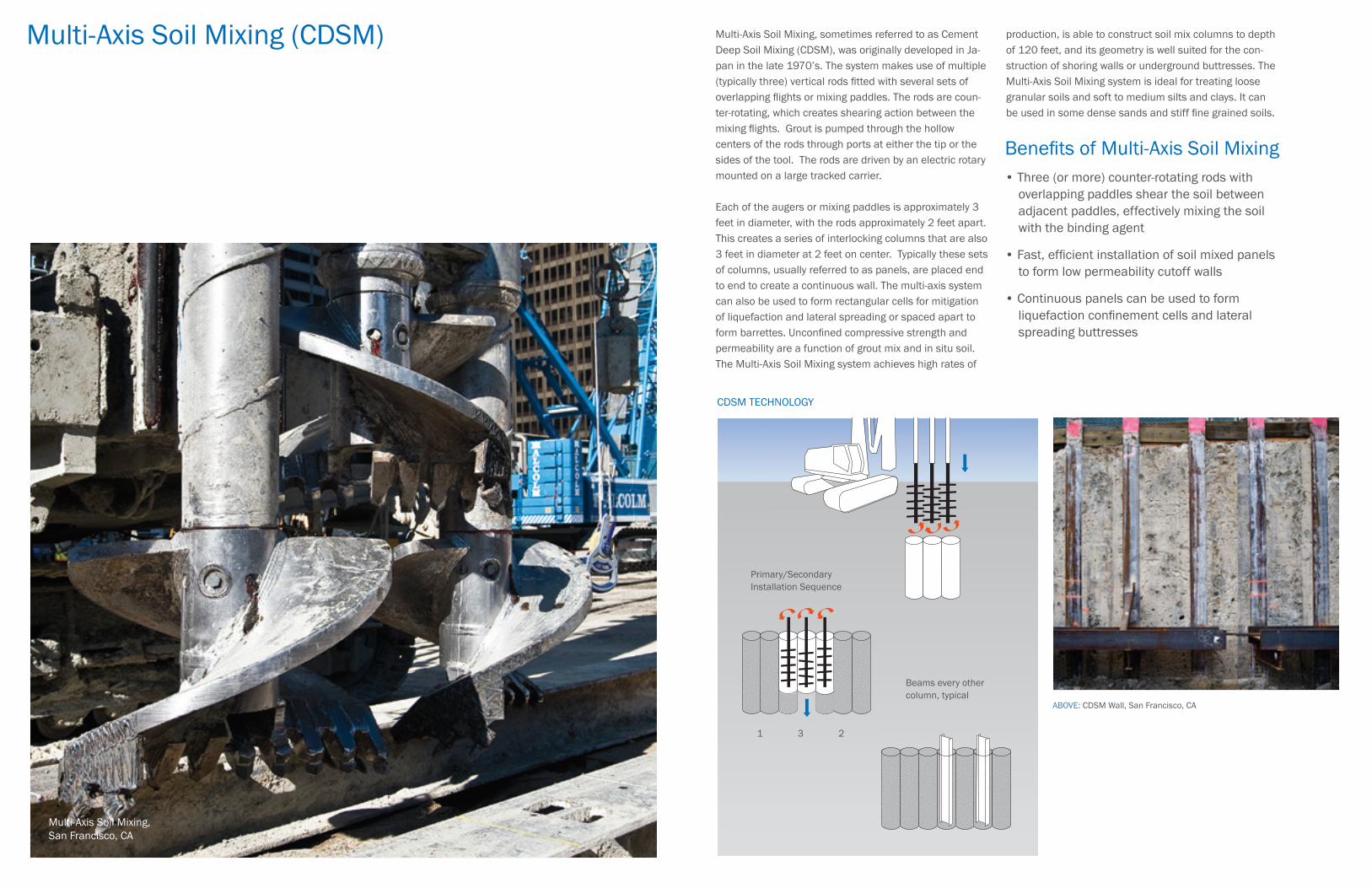
Multi-Axis Soil Mixing, sometimes referred to as Cement Deep Soil Mixing (CDSM), was originally developed in Ja-pan in the late 1970’s. The system makes use of multiple (typically three) vertical rods fitted with several sets of overlapping flights or mixing paddles. The rods are coun-ter-rotating, which creates shearing action between the mixing flights. Grout is pumped through the hollow centers of the rods through ports at either the tip or the sides of the tool. The rods are driven by an electric rotary mounted on a large tracked carrier.
Each of the augers or mixing paddles is approximately 3 feet in diameter, with the rods approximately 2 feet apart. This creates a series of interlocking columns that are also 3 feet in diameter at 2 feet on center. Typically these sets of columns, usually referred to as panels, are placed end to end to create a continuous wall. The multi-axis system can also be used to form rectangular cells for mitigation of liquefaction and lateral spreading or spaced apart to form barrettes. Unconfined compressive strength and permeability are a function of grout mix and in situ soil. The Multi-Axis Soil Mixing system achieves high rates of
ABOVE: CDSM Wall, San Francisco, CA
Benefits of Multi-Axis Soil Mixing • Three (or more) counter-rotating rods with overlapping paddles shear the soil between adjacent paddles, effectively mixing the soil with the binding agent
• Fast, efficient installation of soil mixed panels to form low permeability cutoff walls
• Continuous panels can be used to form liquefaction confinement cells and lateral spreading buttresses
Multi-Axis Soil Mixing, San Francisco, CA
Primary/Secondary Installation Sequence
1 3 2
Beams every other column, typical
CDSM TECHNOLOGY
Deep Soil Mixing (DSM)Single Axis Soil MixingJet Mixing
not normally treated by soil mixing methods. Jet Mixing is fast and the system of choice to construct cylindrical soil cement elements, 2.5 to 3.5 feet in diameter, to depths of up to approximately 65 feet. It is also used to construct soil cement piers to control settlement and increase bearing capacity. It is highly efficient for constructing tangent and secant pile walls, which can be reinforced with wide flange beams (soldier piles) and tiebacks, as required. Because it produces a high quality soil cement material, Jet Mixing can provide permeabilities of 1 x 10⁻⁶ cm/sec or less for cutoff walls and groundwater barriers.
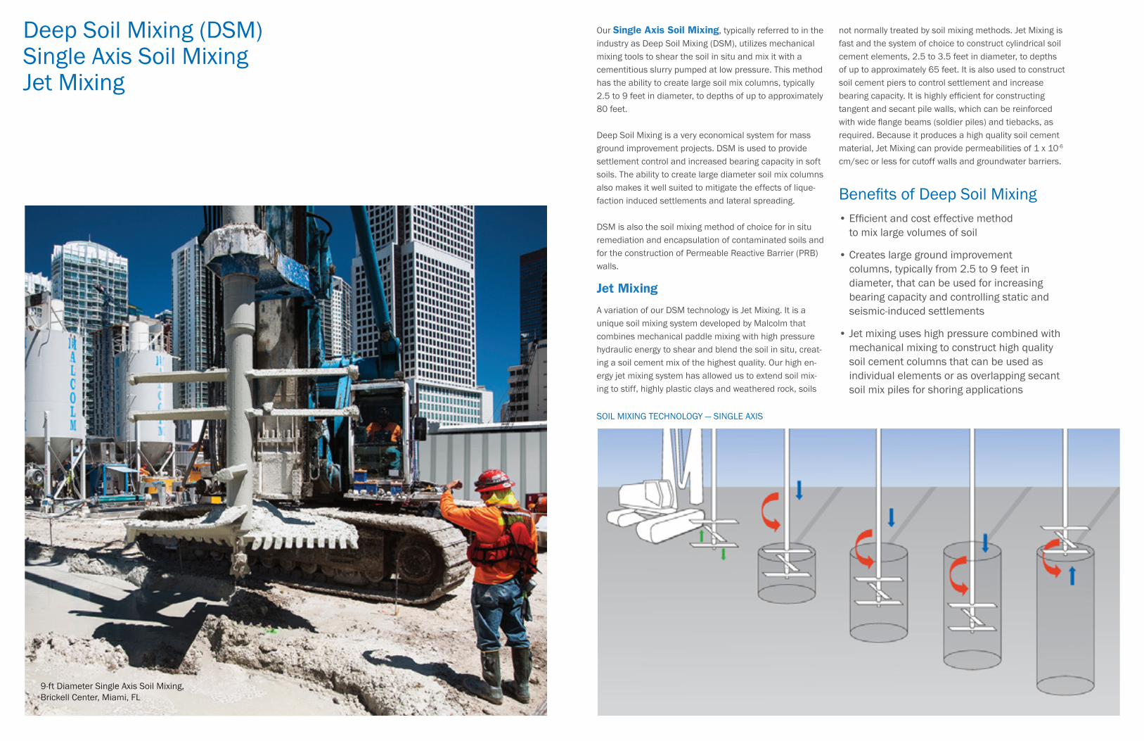
Our Single Axis Soil Mixing, typically referred to in the industry as Deep Soil Mixing (DSM), utilizes mechanical mixing tools to shear the soil in situ and mix it with a cementitious slurry pumped at low pressure. This method has the ability to create large soil mix columns, typically 2.5 to 9 feet in diameter, to depths of up to approximately 80 feet.
Deep Soil Mixing is a very economical system for mass ground improvement projects. DSM is used to provide settlement control and increased bearing capacity in soft soils. The ability to create large diameter soil mix columns also makes it well suited to mitigate the effects of lique-faction induced settlements and lateral spreading.
DSM is also the soil mixing method of choice for in situ remediation and encapsulation of contaminated soils and for the construction of Permeable Reactive Barrier (PRB) walls.
Jet Mixing
A variation of our DSM technology is Jet Mixing. It is a unique soil mixing system developed by Malcolm that combines mechanical paddle mixing with high pressure hydraulic energy to shear and blend the soil in situ, creat-ing a soil cement mix of the highest quality. Our high en-ergy jet mixing system has allowed us to extend soil mix-ing to stiff, highly plastic clays and weathered rock, soils
SOIL MIXING TECHNOLOGY — SINGLE AXIS
Benefits of Deep Soil Mixing• Efficient and cost effective method to mix large volumes of soil • Creates large ground improvement columns, typically from 2.5 to 9 feet in diameter, that can be used for increasing bearing capacity and controlling static and seismic-induced settlements • Jet mixing uses high pressure combined with mechanical mixing to construct high quality soil cement columns that can be used as individual elements or as overlapping secant soil mix piles for shoring applications
9-ft Diameter Single Axis Soil Mixing, Brickell Center, Miami, FL
Jet Grouting MEGA Jet Grouting
Quality assurance and control are an ongoing effort and the responsibility of the field technician. All checking of permanent materials received, field grout testing and record keeping is monitored and recorded. The agreed upon drilling, grouting and injection procedures are developed during the test section and then used in production columns.
A state-of-the-art automatic data acquisition system provides a real time record of all relevant construction parameters for each column installed, including depth, volume injected, operating pressures and column diameters.
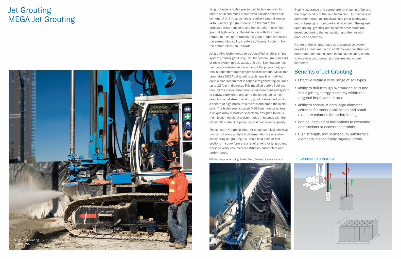
Jet grouting is a highly specialized technique used to create an in situ mass of improved soil also called soil-cement. A drill rig advances a relatively small diameter (4 to 8 inches) jet grout tool to the bottom of the proposed treatment zone and horizontally injects fluid grout at high velocity. The drill tool is withdrawn and rotated at a constant rate as the grout erodes and mixes the surrounding soil to create a soil-cement column from the bottom elevation upwards.
Jet grouting techniques can be classified as either single system (utilizing grout only), double system (grout and air) or triple system (grout, water, and air). Each system has unique advantages and selection of the jet grouting sys-tem is dependent upon project specific criteria. Malcolm’s proprietary MEGA-Jet grouting technique is a modified double fluid system that is capable of generating columns up to 18 feet in diameter. This modified double fluid sys-tem utilizes a specialized multi-chambered drill rod system to convey slurry grout and air to the jetting tool. A high velocity coaxial stream of slurry grout is shrouded within a sheath of high pressure air to mix and erode the in situ soils. The highly sophisticated MEGA-Jet monitor utilizes a unique array of nozzles specifically designed to focus the injection media at a given radius in balance with the chosen flow rate, line pressure, and fluid specific gravity.
The constant variables inherent to geotechnical construc-tion do not allow analytical determinations alone when considering jet grouting. Full scale field tests or test sections in some form are a requirement for jet grouting works to verify assumed construction parameters and performance.
BELOW: Mega Jet Grouting, Ruskin Dam, British Columbia, Canada
Benefits of Jet Grouting• Effective within a wide range of soil types
• Ability to drill through overburden soils and focus jetting energy discretely within the targeted improvement area
• Ability to construct both large diameter columns for mass stabilization and small diameter columns for underpinning
• Can be installed at inclinations to overcome obstructions or access constraints • High strength, low permeability subsurface elements in specifically targeted areas
JET GROUTING TECHNOLOGY
Mega Jet Grouting, U230 Transit, Seattle, WA
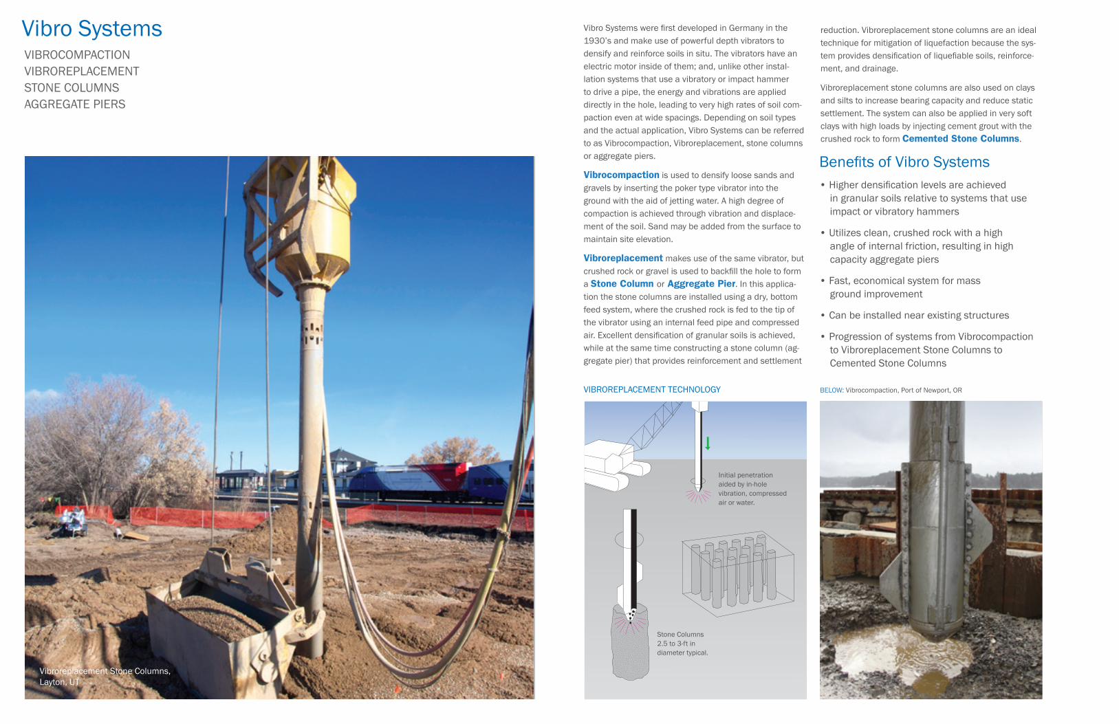
Vibro Systems VIBROCOMPACTION VIBROREPLACEMENT STONE COLUMNS AGGREGATE PIERS
reduction. Vibroreplacement stone columns are an ideal technique for mitigation of liquefaction because the sys-tem provides densification of liquefiable soils, reinforce-ment, and drainage.
Vibroreplacement stone columns are also used on clays and silts to increase bearing capacity and reduce static settlement. The system can also be applied in very soft clays with high loads by injecting cement grout with the crushed rock to form Cemented Stone Columns.
Vibro Systems were first developed in Germany in the 1930’s and make use of powerful depth vibrators to densify and reinforce soils in situ. The vibrators have an electric motor inside of them; and, unlike other instal-lation systems that use a vibratory or impact hammer to drive a pipe, the energy and vibrations are applied directly in the hole, leading to very high rates of soil com-paction even at wide spacings. Depending on soil types and the actual application, Vibro Systems can be referred to as Vibrocompaction, Vibroreplacement, stone columns or aggregate piers.
Vibrocompaction is used to densify loose sands and gravels by inserting the poker type vibrator into the ground with the aid of jetting water. A high degree of compaction is achieved through vibration and displace-ment of the soil. Sand may be added from the surface to maintain site elevation.
Vibroreplacement makes use of the same vibrator, but crushed rock or gravel is used to backfill the hole to form a Stone Column or Aggregate Pier. In this applica-tion the stone columns are installed using a dry, bottom feed system, where the crushed rock is fed to the tip of the vibrator using an internal feed pipe and compressed air. Excellent densification of granular soils is achieved, while at the same time constructing a stone column (ag-gregate pier) that provides reinforcement and settlement
BELOW: Vibrocompaction, Port of Newport, OR
Benefits of Vibro Systems • Higher densification levels are achieved in granular soils relative to systems that use impact or vibratory hammers
• Utilizes clean, crushed rock with a high angle of internal friction, resulting in high capacity aggregate piers
• Fast, economical system for mass ground improvement • Can be installed near existing structures
• Progression of systems from Vibrocompaction to Vibroreplacement Stone Columns to Cemented Stone Columns
Stone Columns 2.5 to 3-ft in diameter typical.
Initial penetration aided by in-hole vibration, compressed air or water.
VIBROREPLACEMENT TECHNOLOGY
Vibroreplacement Stone Columns, Layton, UT
Specialized Geotechnical Grouting
placement to be precisely controlled and isolated at specific depths along the drill hole. Permeation grouting programs can utilize a wide variety of materials ranging from simple neat grout composed of Portland cement and water to complex chemical grouts with set times that can be controlled from less than a minute to several hours. The variety of mix designs and resulting grout properties that can be achieved make permeation grout-ing a versatile ground improvement technique with a wide range of applications.
Compensation Grouting is a sophisticated grouting technique which utilizes pressurized fluid grout to create hydro fractures in the subsurface to lift and level sensi-tive structures typically above new tunnels or adjacent to excavations. The basic principle of this technique is to carefully control grout injection rates and pressures to lift and level structures at the ground surface to compen-sate for ground loss due to local tunneling or excavation work. Drilling to install compensation grout pipes is often performed horizontally from the interior face of a shaft or excavation to provide better control of grout injection locations and help ensure uniform lifting of structures.
Compensation grouting programs include extensive real-time settlement monitoring and grout injection systems to precisely control lifting rates and protect structures both at and below ground surface. Compensation grouting is most often utilized for large projects in urban environments where tunnels and excavations are constructed near sensitive structures which cannot tolerate settlement.
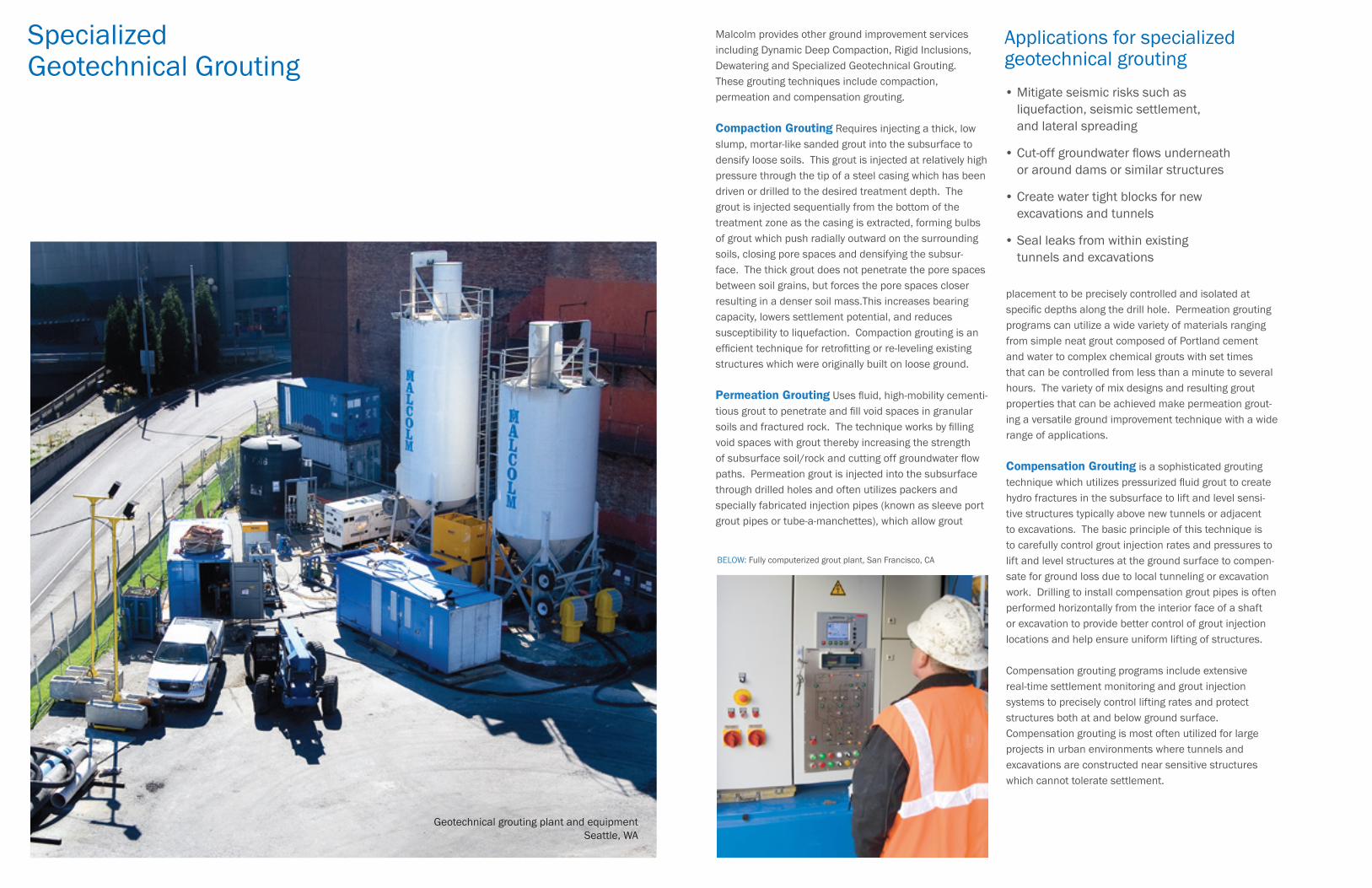
Malcolm provides other ground improvement services including Dynamic Deep Compaction, Rigid Inclusions, Dewatering and Specialized Geotechnical Grouting. These grouting techniques include compaction, permeation and compensation grouting.
Compaction Grouting Requires injecting a thick, low slump, mortar-like sanded grout into the subsurface to densify loose soils. This grout is injected at relatively high pressure through the tip of a steel casing which has been driven or drilled to the desired treatment depth. The grout is injected sequentially from the bottom of the treatment zone as the casing is extracted, forming bulbs of grout which push radially outward on the surrounding soils, closing pore spaces and densifying the subsur-face. The thick grout does not penetrate the pore spaces between soil grains, but forces the pore spaces closer resulting in a denser soil mass.This increases bearing capacity, lowers settlement potential, and reduces susceptibility to liquefaction. Compaction grouting is an efficient technique for retrofitting or re-leveling existing structures which were originally built on loose ground.
Permeation Grouting Uses fluid, high-mobility cementi-tious grout to penetrate and fill void spaces in granular soils and fractured rock. The technique works by filling void spaces with grout thereby increasing the strength of subsurface soil/rock and cutting off groundwater flow paths. Permeation grout is injected into the subsurface through drilled holes and often utilizes packers and specially fabricated injection pipes (known as sleeve port grout pipes or tube-a-manchettes), which allow grout
Applications for specialized geotechnical grouting• Mitigate seismic risks such as liquefaction, seismic settlement, and lateral spreading
• Cut-off groundwater flows underneath or around dams or similar structures
• Create water tight blocks for new excavations and tunnels
• Seal leaks from within existing tunnels and excavations
BELOW: Fully computerized grout plant, San Francisco, CA
Geotechnical grouting plant and equipmentSeattle, WA

www.malcolmdrilling.com
Malcolm Drilling Company was founded in 1962 in San Francisco, California, which remains our headquarters today. Malcolm operates throughout the United States, maintaining a network of regional offices to serve our clients across the country. To learn more about our expertise and for a complete list of locations, visit:
Front cover: Cutter Soil Mixing, Alaskan Way Viaduct Replacement, Seattle, WA Back cover: Cemented Vibroreplacement Stone Columns,
San Luis WTP, Los Baños, CA