cvt development at luk
TRANSCRIPT
157
CVT Development at LuK Dr.-Ing. Hartmut Faust
Dr.-Ing. André Linnenbrügger
Introduction At the last LuK Colloquium in 1994, as part of a comparison of various transmission systems [1], a prototype of a continuously variable transmis-sion (CVT) was introduced. The major advantages of CVT are:
• Increased driving comfort due to smooth transmission ratio changes,
• Low fuel consumption due to large spread of gear ratios, and
• Excellent dynamics of movement.
Despite these advantages, which are particularly evident in larger engines, CVT is marketed for engines only up to approximately 150 Nm torque [2], although a 200 Nm [3] version recently became available in Japan.
In the interim, LuK has used the belt/chain principle to develop CVT com-ponents for torques up to and exceeding 300 Nm that are ready for mass production. This presentation will showcase some of the special features engineered into these components.
158
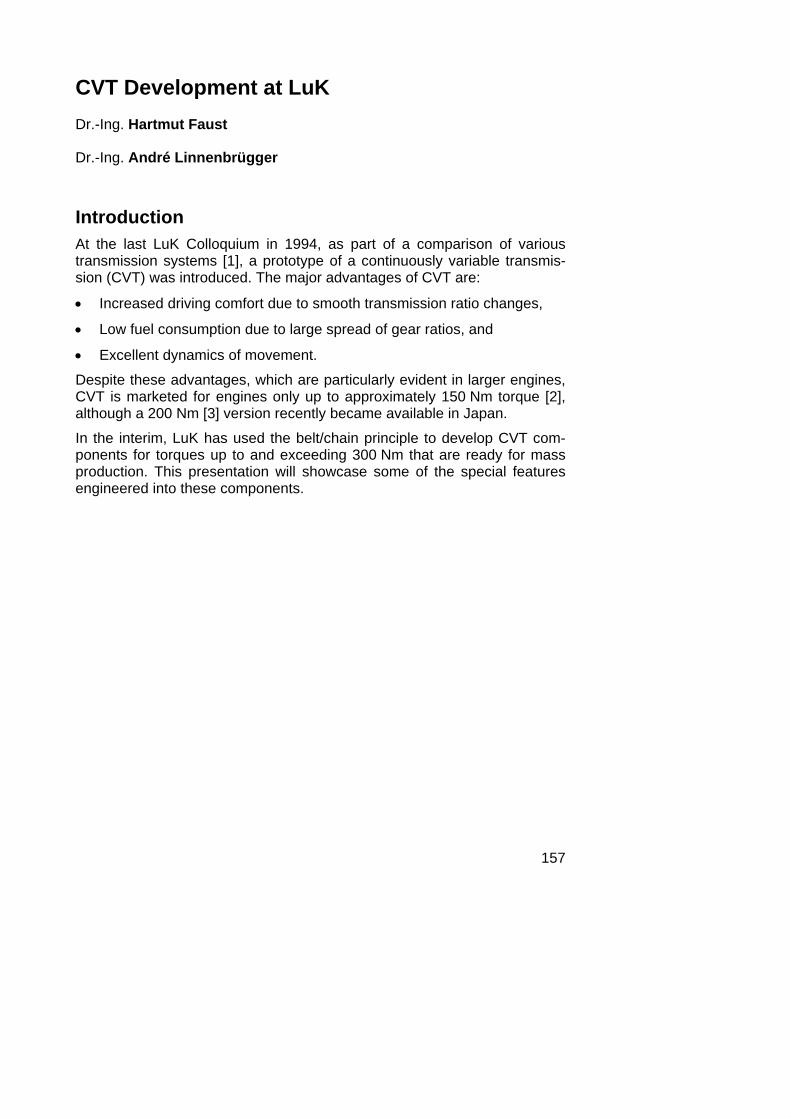
Functions of the Hydraulic Control System Figure 1 compares the function of hydraulic control systems for 5-speed step automatics and CVT.
The hydraulic system must serve a start-up device and a reverse unit in both kinds of transmissions. In a 5-speed automatic, it is also responsible for shifting gears, which requires a total of approximately six solenoids and approximately 20 valves, depending on the design. In a CVT transmission, the only additional function is the adjustment of the clamping force between the pulley flanges and the chain and the adjustment of the CVT ratio. This type of design requires only three solenoids and nine valves.
start-up device
1st gear
reverse
2nd gear
3rd gear
4th gear
5th gear
5 AT CVT
~ 6 solenoids~ 20 valves
3 solenoids9 valves
start-up device
clamping load
reverse
ratio control
LuK-CVT:
Figure 1: Comparison of hydraulic control systems for 5-speed step automatics and CVT
Using the general concepts outlined during this presentation, a compact CVT hydraulic control can be realized. A dual-stage torque sensor arranged directly in the power flux of the variable speed mechanism, where it can provide excellent functional safety, ensures very accurate, highly dynamic clamping control.
LuK is supervising both the development and the production of the hydrau-lic control system.

159
Clamping System Requirements A whole range of factors affecting the entire drive train from the engine to the wheels influences the required clamping force (Figure 2).
• The engine torque, which is dependent on the driver and on electronic engine controls, is one factor.
• Converter torque multiplication and clutch or lock-up clutch controls cause additional torque to act on the system.
• Gear ratio is a factor, because it makes a difference whether torque is transmitted by the primary pulley in underdrive (UD) with a small effec-tive radius or in overdrive (OD) with a large effective radius.
• The lowest occuring friction coefficient determines the required clamp-ing force.
• The influence of the wheels on the torque to be transmitted by the vari-able speed mechanism is critical because torque can change suddenly and unpredictably, such as when a wheel leaves the road surface, or during the transition from an icy patch to normal road. An appropriately controlled clutch can make it possible to limit these influences.
engine torque ratiodynamic wheel
torque
engine
friction coefficient
wheel
TE
TW
primarypulley
secondarypulley
chain
torque ratio andcontrol of lock-up
or clutch
Figure 2: Influences on the required clamping force in the variable speed mechanism

160
00
torque T1 [%]
clam
ping
forc
e F
[%]
25 50 75 100
25
50
75
100
125
iVar = 2.5
1.0
0.4
Figure 3a: Required minimum clamping force for various transmissions over torque
For a given coefficient of friction, the required minimum clamping force in-creases in a linear fashion as torque increases. This correlation is depicted for various transmissions in Figure 3a.
A full-load safety factor of approximately 25 % above the slip limit allows for fluctuations in the friction coefficient, as shown for the underdrive transmis-sion in Figure 3b. This is intended to prevent slipping. Greater safety mar-gins lead to unnecessarily high forces and lower efficiency. In conventional systems, the full safety margin is present even when torque is low [2], be-cause the strength of unpredictable jolts is not dependent on the adjacent torque. Thus, systems incapable of quickly changing the clamping force with the aid of automatic pumping action require a constant reserve. Con-sequently, at 1/4 of the nominal torque, the excess clamping force in-creases to 100 % in relation to the adjacent torque. One can see the nega-tive effects on the variable speed mechanism’s efficiency and the effect of the unnecessarily high resulting system pressure on pump losses. This also results in unfavorable fuel consumption under partial loads.

161
00
torque T1 [%]
clam
ping
forc
e F
[%]
25 50 75 100
25
50
75
100
125
iVar = 2.5
conventionalsystem
torquesensor
slip limit
with margin for torque peaks
with constant safety factor
Figure 3b: Progression of clamping force over torque in conventional sys-tems with clamping force offset and with hydro-mechanical torque sensors with a constant safety factor
The LuK system, with its hydro-mechanical torque sensor, uses a constant safety factor, i.e., the absolute excess clamping force is reduced as torque decreases. Almost instantaneously, it records the torque directly at the variable speed mechanism, and it can also provide short-term pumping action with no assistance from other control devices in the event of drive-side or output-side impacts. This is described in more detail below. By avoiding excess clamping force, the transmission in this type of system also works very efficiently during partial load operation, which is extremely im-portant for fuel consumption.
An analog depiction of the minimum required clamping force for various torques over CVT ratio is provided in Figure 4a. The result is a hyperbola-like curve of required clamping force over transmission ratio.
162
one stage torque sensor
2.5 1 0.40
25
50
75
100
CVT ratio i
clam
ping
forc
e F
[% ]
T1: 100 %
T1: 25 %
125
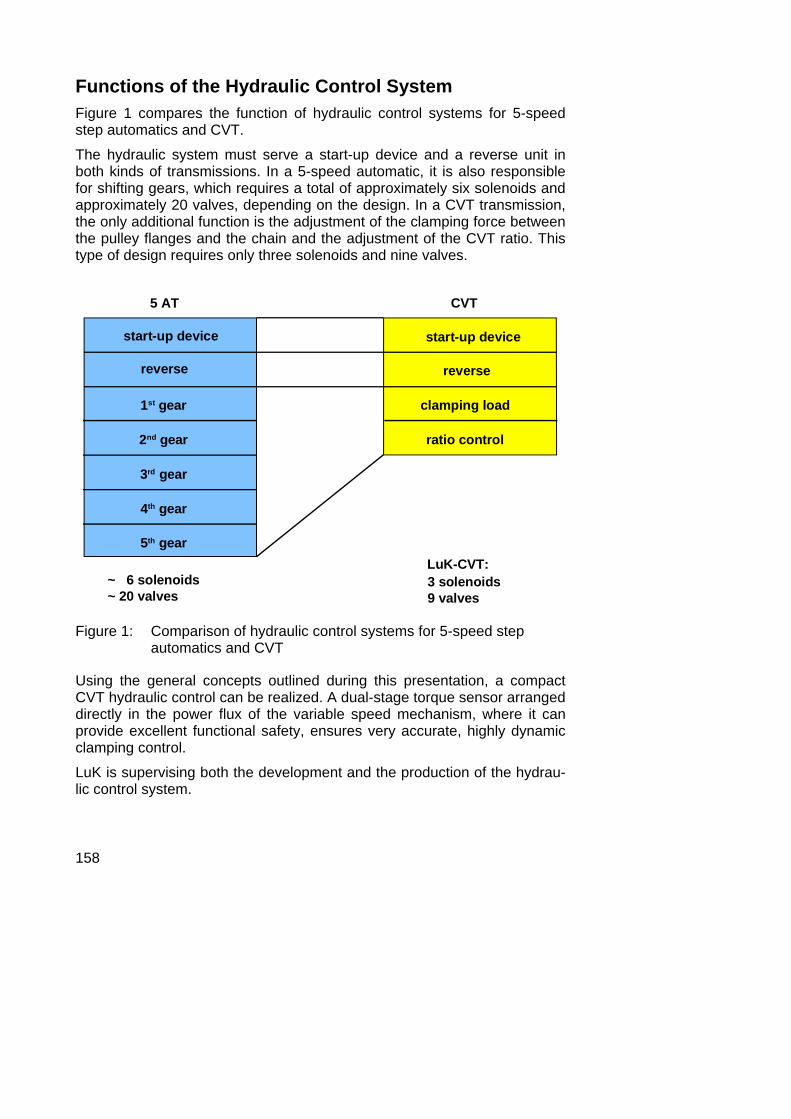
Figure 4a: Possible clamping force for various torques over CVT ratio with a single-stage torque sensor
A constant characteristic clamping curve is undesirable because the great-est portion of driving time is spent in overdrive. In Figure 4b, total driving time is divided into time shares showing the results of longer trips on coun-try roads and highways in a CVT vehicle in the 300 Nm segment.
0.412.5
time
shar
e t [
% ]
20
40
60
0
country road & highway
CVT ratio i
Figure 4b: Time shares measured on country roads and highways in the CVT vehicle

163
Two-stage switching of the torque sensor’s characteristic curve, as shown in Figure 4c, seems to be well suited to the distribution of driving time shares. Time shares spent in underdrive with occasional periods of un-necessarily high clamping force are very much underrepresented. Simula-tions performed at LuK have shown that fuel consumption at the theoretical optimum clamping force is only approximately 0.3 % lower than the fuel consumption achieved by this simpler two-stage characteristic curve.
CUD
CUD
COD
COD
2.5 1 0.40
25
50
75
100
CVT ratio i
clam
ping
forc
e F
[% ]
0.412.5
20
40
60
0
country road & highway
T1: 100 %
T1: 25 %
125
time
shar
e t [
% ]
dual stage torque sensor
Figure 4c: Measured time shares (above) and clamping force with dual-stage torque sensor (below)
Dual-Stage Hydro-Mechanical Torque Sensor The previous section discussed the considerations leading to the develop-ment of the dual-stage torque sensor. The basic principle behind the famil-iar single-stage hydro-mechanical torque sensor is depicted in Figure 5. Torque is induced using a ramp plate, through which the power flows over balls to an axially moveable sensor piston supported by oil pressure. Oil coming from the pump flows out through a discharge bore whose flow re-sistance changes with the movement of the sensor piston until equilibrium is established between the axial force of the ball ramp and the compression

164
force. In this manner, the torque sensor adjusts the pressure routed directly into the clamping cylinder in exact proportion to the adjacent torque.
The moveable sensor plate closes the discharge bore if there is a sudden change in torque. If torque continues to rise, the sensor plate then actively forces the oil out of the torque sensor chamber into the pulleys to increase the clamping force. In other words, the torque sensor acts like a pump for a short time. This “back-up pump”, which works only when needed and does not require any drive power, can provide a short-term flow of more than 30 l/min in the event of a sudden change in torque.
p
FT
Figure 5: Principle behind the single-stage hydro-mechanical torque sensor
To produce a two-stage characteristic curve, the pressure area of the sen-sor piston is divided into two parts (Figure 6). In underdrive, where clamp-ing force must be higher to transmit the torque due to the small effective radius of the chain, pressure acts on only one part of the surface. To equal-ize the ramp force, supplied by torque, the pressure in the torque sensor must be high and consequently also in the clamping cylinder.
In overdrive, beyond the switch point, pressure acts on both parts of the surface. This is why the clamping force is lower at a given torque.

165
Changing the gear ratio creates axial displacement of the moveable pulley flange of the primary pulley. This then switches the characteristic curve directly by enabling or disabling the second partial surface. In underdrive, the second partial surface is ventilated by the right switch bore at atmos-pheric pressure as shown in Figure 6. However, in overdrive, this bore is closed by the moveable pulley flange, and the left switch bore provides a connection to the hydraulic fluid.
UD
OD
Figure 6: Principle behind the dual-stage torque sensor with high clamping force in underdrive (above) and lower clamping force in overdrive (below)
Requirements of the Adjusting System Now the oil flow required for rapid adjustment of the variable speed mecha-nism will be considered. Figure 7 illustrates the necessary flows for a rapid adjustment to underdrive. Rapid adjustment is required during sharp brak-ing maneuvers where underdrive transmission is desired immediately after the vehicle comes to a stop, after kickdown actuations, or on driver de-manded gearshifts.

166
The flows listed are required for the given system reaction time as a func-tion of initial driving speed, and thus, the braking time. If a conventional variable speed mechanism system is installed, the flow must exceed 13 l/min at the critical speed (for this case) of approximately 25 km/h. Con-trastingly, the required flow for an adjustment cylinder operating on the LuK double piston principle is reduced to approximately one-third of the conven-tional system’s requirements. This is possible because the pump must acti-vate only part of the cylinder, the so-called adjustment cylinder, when it adjusts the variable speed mechanism.
0
3
6
9
12
15
0 10
speed v [km/h]
20 30 40 50 60
conventional system
LuK double piston
oil f
low
QVa
r [L
/min
]
a = 8 m/s2
T = 0,2 s
Figure 7: Required oil flow into the pulley cylinder for rapid underdrive adjustment in conventional systems and in the LuK double piston system
LuK Double Piston System with Dual-Stage Torque Sensor Conventional systems have one pressure cylinder on the drive-side pulley and one on the output-side pulley (Figure 8 left). The oil flows from the pump to a control unit that directs the pressure to be induced in the cylin-ders. These cylinders combine clamping and transmission adjustment func-tions into one component. The primary cylinder surface is often designed to be significantly larger than the secondary surface.
167
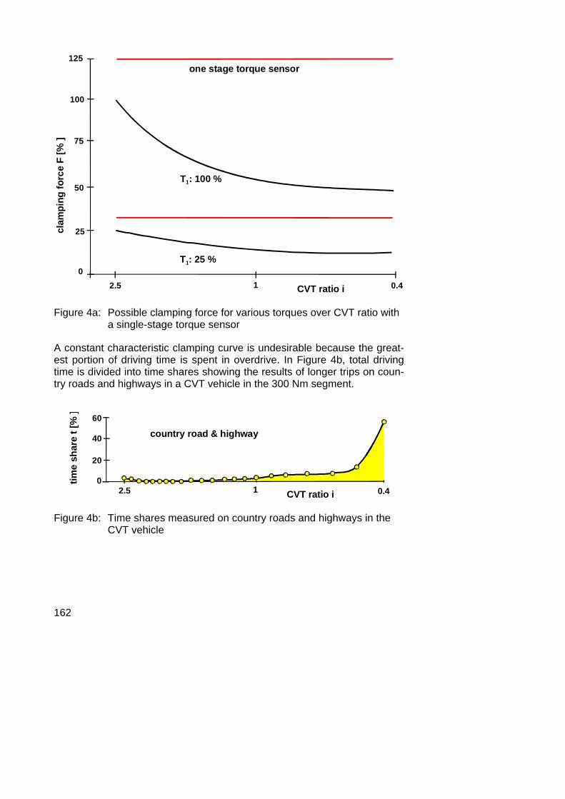
The primary reason for this is the inability of many CVT hydraulic systems to set primary cylinder pressure higher than secondary cylinder pressure.
For a rapid adjustment into underdrive mode, the pump must satisfy the high flow requirements of the entire secondary cylinder surface. At the same time, hydraulic fluid is released from the primary pulley into the oil sump, which results in an energy loss. This occures similarly for overdrive adjustments. Therefore, a pump with a large transport volume is necessary to fulfill the system’s dynamic requirements, with the corresponding nega-tive effect on the pump’s energy requirements.
LuK double piston
clampingcontrol
conventional system
clamping & ratio control ratio control
Figure 8: Principle behind CVT hydraulic systems and comparison of vol-ume flows during a rapid adjustment to underdrive performed by a conventional system (left) and by the LuK double piston model (right)
Unlike the conventional system, the LuK double piston model divides the cylinder areas into:
• partial surfaces (red) that ensure clamping, and
• smaller, separate partial surfaces (blue or green) that are responsible for making adjustments.

168
As we have already discussed, the dual-stage torque sensor ensures clamping. In two stages, the sensor adjusts the pressure in the clamping cylinders in strict proportion to torque as a function of the CVT ratio.
Adjusting the pulleys requires only a small volume of oil to service the com-paratively small surfaces of the adjustment cylinders. When the variable speed mechanism is adjusted, the clamping oil, which is under high pres-sure, is transported directly from one pulley to the other without requiring any additional expenditure of energy. This means the pump for the LuK double piston principle is significantly smaller than pumps for conventional CVT systems, which improves overall transmission efficiency and subse-quent fuel consumption.
In Figure 9, the basic idea of this concept, relating to the expenditure of energy during ratio adjustment, can be clearly seen. As far as the conven-tional system is concerned, pressurized oil is released from one pulley into the oil sump. In order to facilitate filling of the other pulley, oil from the sump, at atmospheric pressure, has to be raised to the level of pressure demanded for operation, requiring an appropriately high expenditure of energy. This is different to the LuK Double Piston principle: here, the oil is transported directly from one pulley to the other, maintaining the high pres-sure level, without additional energy expenditure.

169
F
F
h=0
conventional system
LuK double piston
h
Figure 9: Comparison of the energy expenditure for adjusting the pulleys for the conventional system (above) and the LuK double piston concept (below), which is more favourable from an energy point of view
The upper portion of Figure 10 depicts the application of the double piston and dual-stage torque sensor concepts with the primary pulley for under-drive; overdrive is depicted in the lower portion. The hydraulic fluid (red) flows from the pump into the torque sensor chamber and off to the left over the discharge edge with lower pressure. The clamping force set by the torque sensor to create equilibrium of forces directly affects the clamping cylinder of the primary and (not pictured) secondary pulley simultaneously. The second chamber of the torque sensor (blue) is radially further outward. It is not under pressure because it is ventilated by the right switch bore. The path of the hydraulic fluid to the left switch bore is blocked by the altered position of the sliding pulley element.
The path of the adjustment oil to the radially outer primary adjustment cyl-inder is indicated in green. The total axial force is equal to the compressive force of the clamping cylinder plus the additional compressive force of the adjustment cylinder. Pressure acts upon the adjustment cylinder so that it can not only make adjustments, but also secure the ratio by axially loading the primary and secondary pulleys in relationship to the force requirements.

170
In this manner, the entire available surface area for the pulley’s size is used to generate axial force.
UD
OD
Figure 10: Design of primary pulley with double piston and dual-stage hydro-mechanical torque sensor
In the overdrive position, with correspondingly low clamping force require-ments, the sliding pulley element moves towards the fixed pulley element (bottom). This closes the right ventilation switch bore and opens the left bore leading to the clamping cylinder, allowing the hydraulic fluid to flow through this bore system into the second torque sensor chamber. Because pressure is being applied to a larger surface area, the torque sensor de-creases the clamping force accordingly, despite the fact that the adjacent torque remains constant. The adjustment cylinder continues to operate

171
as above. The torque sensor’s ramp plates are manufactured from sheet steel. The teeth for the plates are also formed during the manufacturing process.
Figure 11 illustrates the development of torques, clamping force and wheel revolutions for a vehicle equipped with the system described while it moves onto a partially frozen section of road and during its subsequent transition to normal road.
The lower portion of the figure illustrates that the right drive wheel rotates at a speed corresponding to the gradually increasing vehicle speed, while the left drive wheel spins with rapidly increasing slip. After the vehicle has reached the normal road surface, the slipping wheel is slowed in large gra-dients. At this point, the right wheel accelerates more strongly in tandem with the vehicle. Following the slip phase, both wheels accelerate in sync with the vehicle.
engine torque
clamping pressurevariator torque
left
right
left & right
ice grip
whe
el s
peed
nto
rque
Tcl
ampi
ng p
ress
ure
p
time t
Figure 11: Torque and clamping force curve while driving onto partially frozen road, followed by a transition to normal roads
The top portion of the figure illustrates the development of torque and the clamping force set by the torque sensor. The internal engine torque re-mains almost constant during the approach, but while the vehicle is on the
172
ice, most of the torque is used to accelerate the rotating parts. The variable speed mechanism torque is correspondingly low during this phase.
During the slip phase on the normal (non-slippery) road, the variable speed mechanism torque increases drastically to a value far above the engine torque. This is caused by the large negative acceleration of the rotating parts along the entire drive train, including the engine. The engine torque and variable speed mechanism torque are not substantially identical until the subsequent normal acceleration phase.
Because the torque sensor records the exact torque induced in the variable speed mechanism, the clamping force set by the torque sensor can behave in a static or dynamic manner analogous to the variable speed mechanism torque. The short-term pumping capacity of the torque sensor and its ability to make rapid adjustments ensures highly dynamic clamping force adjust-ment in accordance with the adjacent torque.
A further advantage of the torque sensor is its ability to make extremely precise adjacent torque-clamping force conversions using only geometrical data. This allows the clamping force to be set precisely at the minimum point even under partial load operation, where the torque values given by the engine control system possess a greater degree of uncertainty. This also has a beneficial effect on fuel consumption.
The CVT Chain as Contact Element Using a rocker pin chain made by P.I.V. Antrieb Werner Reimers as a start-ing point, LuK made further improvements to the CVT chain for automotive applications. The development process focused on improving its strength to achieve the high required power density and on improving its acoustic properties.
Figure 12 illustrates the CVT chain for applications producing torque up to 300 Nm. It is constructed of various links, which form the strands, the rocker pins, and retaining elements.

173
chain links rocker pinshort long
retaining pin
Figure 12: Design and components of the LuK-P.I.V. CVT chain
The CVT chain has the following characteristics:
• It has low fuel consumption and excellent power transmission per-formance. This is made possible by the rocker pin design of the CVT chain, which allows short rotations around the pulley flanges and a high spread of gear ratios.
• The CVT chain allows transmission of high torque levels. Thicker links on the outside edges of the strands equalize load distribution.
• Because the rocker pins are able to “seesaw”, the chain experiences low internal friction losses, ensuring high transmission efficiency.
• The CVT chain is resistant to axle offset due to the rocker pins’ crow-ned faces. In combination with cambered pulley flanges, these ele-ments reduce additional axle offset created whenever ratio is chan-ged. Furthermore, the CVT chain is resistant to pulley deformation under load, angular errors and relative rotations between the fixed and moveable pulley flanges. Ball-guidance for the axially adjustable pulley flanges are therefore unnecessary.
• The CVT chain produces low axial forces acting on the primary pul-ley. This allows work to be done at low hydraulic pressure with the gi-ven cylinder surfaces, an additional plus for transmission efficiency.

174
• The strand is designed with a basic three link assembly module, allo-wing the base pitch to be small. In a short chain link, a link clip is all that separates neighboring rocker pins from each other. A second, different link length allows favorable acoustic behavior to be achieved by cal-culating the optimal pitch sequence of long and short links.
Durability Calculation and Design of the CVT Chain Determining the operational life of a CVT chain is divided into four sub-processes, each of which is depicted schematically in Figure 13.
� � � � � � � � � � � � � � � � � � � � � � � � � � � � � � � � � � � � � �
�
� � �
� � � � �
� � � � � � � � � � � � � � � � � � � � � �� � � � �
� � � � � � � � � � � � � � �
� � � � � � � � � � � � � � � � � � � � �
� �
� ��
���
� � � !
"""
"""
"""
"""
�
� �
#$
Figure 13: Load analysis and calculation of operational life of the CVT chain using car manufacturer’s loading spectrum as a basis

175
(1) Classification of the customer’s loading spectrum Ideally, the customer provides a loading spectrum that is representative of the required performance specifications. In addition to the engine characte-ristics and the test track profile, gross weight, drive train design, and the vehicle’s chassis and tires also play a role in the load placed on the CVT.
The available curves for engine torque, engine speed, and CVT ratio are prepared for damage calculations by gathering classes of these parame-ters. In this manner, we can gather several hundred different sets of driving conditions with their respective percentage of the collective running time.
(2) Calculation of chain forces Tight side and slack side forces acting on the CVT chain for each opera-tional point in (1) are calculated. In addition to the peripheral forces result-ing from torque transmission, axial forces for both pulleys are also included in the calculation, which is based on Dittrich’s theory [5, 6].
(3) Calculation of component stress Using the chain tensile force figures as a starting point, appropriate calcula-tions are made to determine the stress distribution for each point of the spectrum. This applies both to the distribution of forces within the strands and to the distribution of tension in the links and rocker pins.
(4) Durability calculation Using damage accumulation hypotheses, a calculation of operational life is performed based on experimentally gathered Wöhler material or compo-nent curves. The resulting damage total provides information on the feasibi-lity of the prospective chain design.

176
CVT Chain Load Distribution Figure 14 illustrates the load distribution for the chain strand during un-derdrive ratio at full engine torque.
Figure 14: Unequal distribution of link forces on the CVT chain during un-derdrive ratio at maximum engine torque, including the effects of rocker pin deformation
Clamping forces, tensile forces, and induced frictional forces deform the rocker pins, shown in an enlarged view on the right side of Figure 14. De-formation places stress on the rocker pins and leads to an unequal distribu-tion of link forces, shown here by the differently colored areas.
Introducing links of varying thickness was a definite improvement over known designs. The tensioning of the components was optimized using finite element method (FEM). Without altering the CVT chain’s main dimen-sions, its life was more than doubled by all the improvements made using the given spectrum.

177
Optimization of Acoustics Special attention was given to optimizing the acoustics of the CVT chain.
By using links of different lengths and carefully sequencing them along the CVT chain, we suppressed the disturbing monotone note to a large degree. The mixture ratio and the pitch sequence were mathematically optimized for the corresponding application.
Figure 15 uses plastic-head measurements in the vehicle’s interior to illus-trate the success of such computer-assisted optimization processes. Ac-celeration trials at speeds between approximately 30 and 80 km/h were performed with a special measurement parameter set for transmission con-trol that maintained a constant engine speed. This procedure allowed the various sources of noise (listed below) to be clearly separated from each other:
• Horizontal Lines: Drive (engine, assembly, transmission input),
• Diagonal Lines: Output (wheels, axles, transmission output),
• Curved Lines: Chain actuation of the variable speed mechanism.
� � � � � � % � � � � � � � & � � � �
� � � � � � � � � � � � � � � � � � � ' � � � �
Figure 15: CVT chain acoustics: optimization via calculated simulations and advance planning of the pitch sequence of short and long links

178
Peaks in the form of curved lines are visible on the left side of Figure 15. These are the points at which the CVT chain engages the pulleys, points considered disturbing here.
The CVT chain on the right side of Figure 15, after improvements to its mix-ture ratio and pitch sequence, has almost no disturbing monotone note at all. This allowed us to achieve favorable acoustic behavior.
Other important influences on the acoustics of the complete CVT system are the pulley arrangement, housing design, and all other paths of struc-tural noise transfer. These factors are additional candidates for acoustic optimization.
Summary LuK has developed CVT components for torque up to 300 Nm and beyond. Their most important special features are:
• Precise control of the minimum clamping force required for proper torque transmission and high efficiency; this is accomplished by means of a dual-stage hydro-mechanical torque sensor that measures adjacent torque at the variable speed mechanism with great accuracy and ensures highly dynamic clamping. It is also ca-pable of providing additional short-term pumping action when neces-sary.
• Excellent adjustment dynamics at low pump capacity, accomplished by direct transport of the clamping oil, which is under high pressure, from one pulley to the other when adjustments are made; made possible by the LuK double piston concept with separate cylin-ders for clamping and adjustment.
• Greater spread of gear ratios, sturdy design, high efficiency and opti-mized acoustics in the power transmission element; made possible by the CVT chain, developed with the aid of computer simulations, for torques up to 300 Nm and beyond.

179
Literature [1] Jürgens, G.: Vergleich von Getriebesystemen. [Comparison of Transmission Systems],
5th LuK Symposium, Bühl, May 27, 1994, p. 145 – 173
[2] Fuchino, M.; Ohsono, K.: Development of Fully Electronic Control Metal Belt CVT. International Conference on Continuously Variable Power Transmissions CVT ´96, September 11-12, 1996, Yokohama/Japan, p. 23 - 32
[3] Kurosawa, M.; Fujikawa, T.: High Torque Belt CVT with Torque Converter. Symposium Steuerungssysteme für den Antriebsstrang von Kraftfahrzeugen [Symposium on Control Systems for Motor Vehicle Drive Trains], September 18 – 19, 1997, Berlin, p. 1 – 12
[4] Rattunde, M.; Schönnenbeck, G.; Wagner, P.: Bauelemente stufenloser Kettenwandler und deren Einfluß auf den Wirkungsgrad [Components of Continuously Variable Chain Transmission and their Influence on the Efficiency]. VDI-Berichte [VDI Reports] 878 (1991), p. 259 - 275
[5] Dittrich, O.: Theorie des Umschlingungstriebes mit keilförmigen Reibscheibenflanken [Theory of the Chain Drive with V-shaped friction pulley flanks]. Dissertation Technical University Karlsruhe, 1953
[6] Dittrich, O.: Anwendung der Theorie des keilförmigen Umschlingungstriebs auf stufen-lose Getriebe [Application of the Theory of V-shaped Chain Drives on Continuously Va-riable Transmissions]. Bad Homburg, 1992