cw 6000 captive winch manual issue a - lewmar cw 6000 manual.pdf · traction drive unit by...
TRANSCRIPT
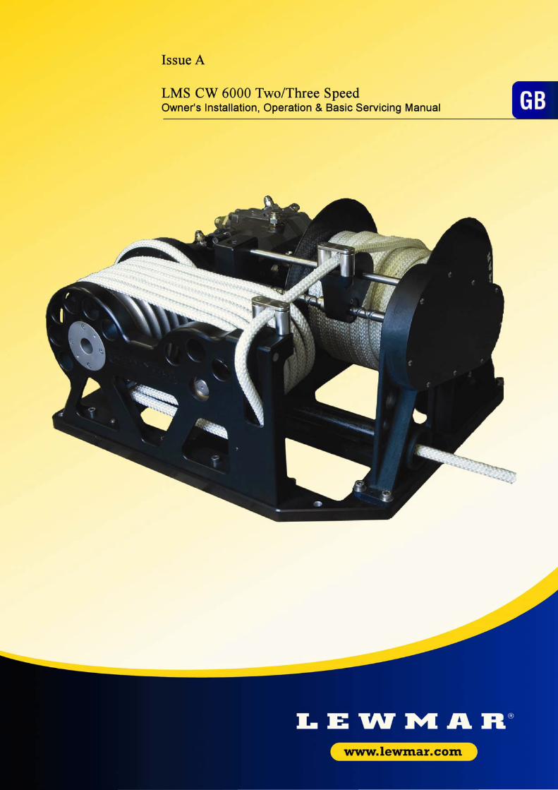
INTRODUCTION The Lewmar Line Management System LMS CW 6000 Winch is a hydraulic powered self-contained winch, offering significant and desirable advantages over other captive winches currently available. It has been designed to suit the needs of large cruising yachts, where highly loaded sheets need to be stowed quickly and safely with the minimum of fuss or effort. The LMS CW 6000 Winch comprises of two elements, a hauling section and a stowing section, mounted on a common base plate. The design of the hauling section helps eliminate rope damage caused by friction on the highly loaded traction drive unit by employing a separate idler drum around which the line is fed. The idler drum is positioned so as to provide a perfect lead, allowing the rope to be stored neatly at low tension preventing damage to the rope and eliminating the possibility of riding turns. The line is then stored at low tension on the separate stowing drum. The hauling section employs an efficient variable speed motor giving good spread of line speed with minimum power demand. A choice of control systems enables the winch to be used in fixed speed or fully proportional modes. The LMS CW 6000 Winch also eliminates long entry lead angles with its ability to be close coupled to the point of sheet entry. The LMS CW 6000 is fitted with a High Load release system and an optional automatic line pay out. This plus the simple hydraulic connections ensures that the LMS CW 6000 Winch occupies only the minimum of precious space on today’s complex yachts.
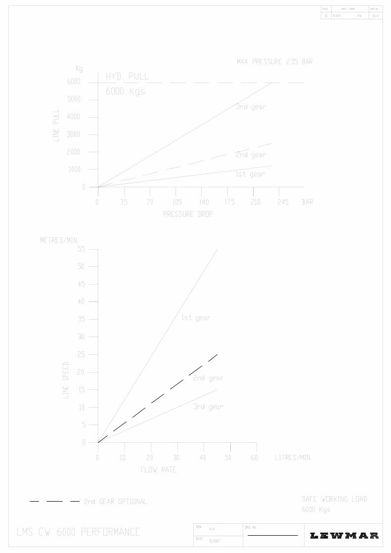
SPECIFICATION Line Diameter Range 14mm, 16mm, 18mm, 20mm, 22mm Diameter, specified at time of purchase. Stowing Unit: Stowing Capacity 14mm Diameter Line - 110 Meters 16mm Diameter Line - 90 Meters 18mm Diameter Line - 75 Meters 20mm Diameter Line - 60 Meters 22mm Diameter Line - 50 Meters Electrical Requirements 24 V DC + / - 15% 5.0 Amps Maximum Hydraulic Requirements Maximum Flow 45 Litres / Min Maximum Pressure "A” & "B" 235 Bar Maximum Pressure "Drain" 4 Bar Hydraulic Fluid - Mineral Oil Confirming to ISO 3448 (BS 4231) Viscosity Grade 32, Type HM Filtered to cleanliness standard ISO 4406 (BS 5540) Class 18 / 13 or better. Fluid optimum operating temperature range 20 °C to 50 °C Line Speed @ 45 l/min First Gear (High speed) 55 Meters / Min Second Gear (Middle speed) 25 Meters / Min Third Gear (Low speed) 10 Meters / Min Maximum Line Pull First Gear (Low Torque) 1000 Kg @ 210 Bar Second Gear (Middle Torque) 2200 Kg @ 210 Bar Third Gear (High Torque) 6000 Kg @ 235 Bar Second gear is optional and is dependant on the control system used. NOTE: Depending on the control system the winch automatically changes from first (high) gear to second (middle) gear and from second (middle) to third (low) when the load causes the hydraulic pressure to rise above 210 Bar. Unit Overall Dimensions 765mm x 615mm x 280mm Unit Weight 146 Kg
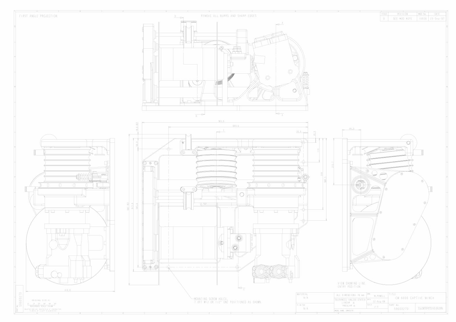
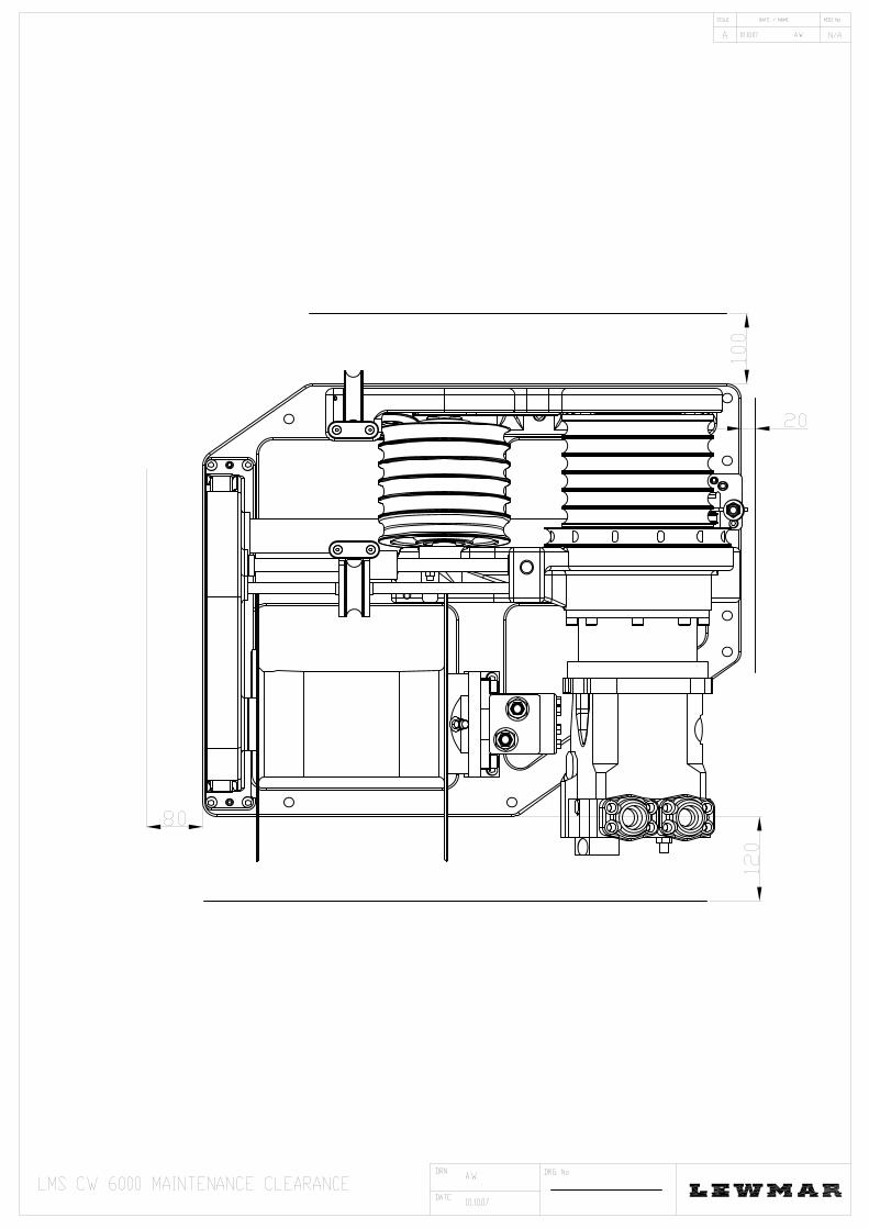
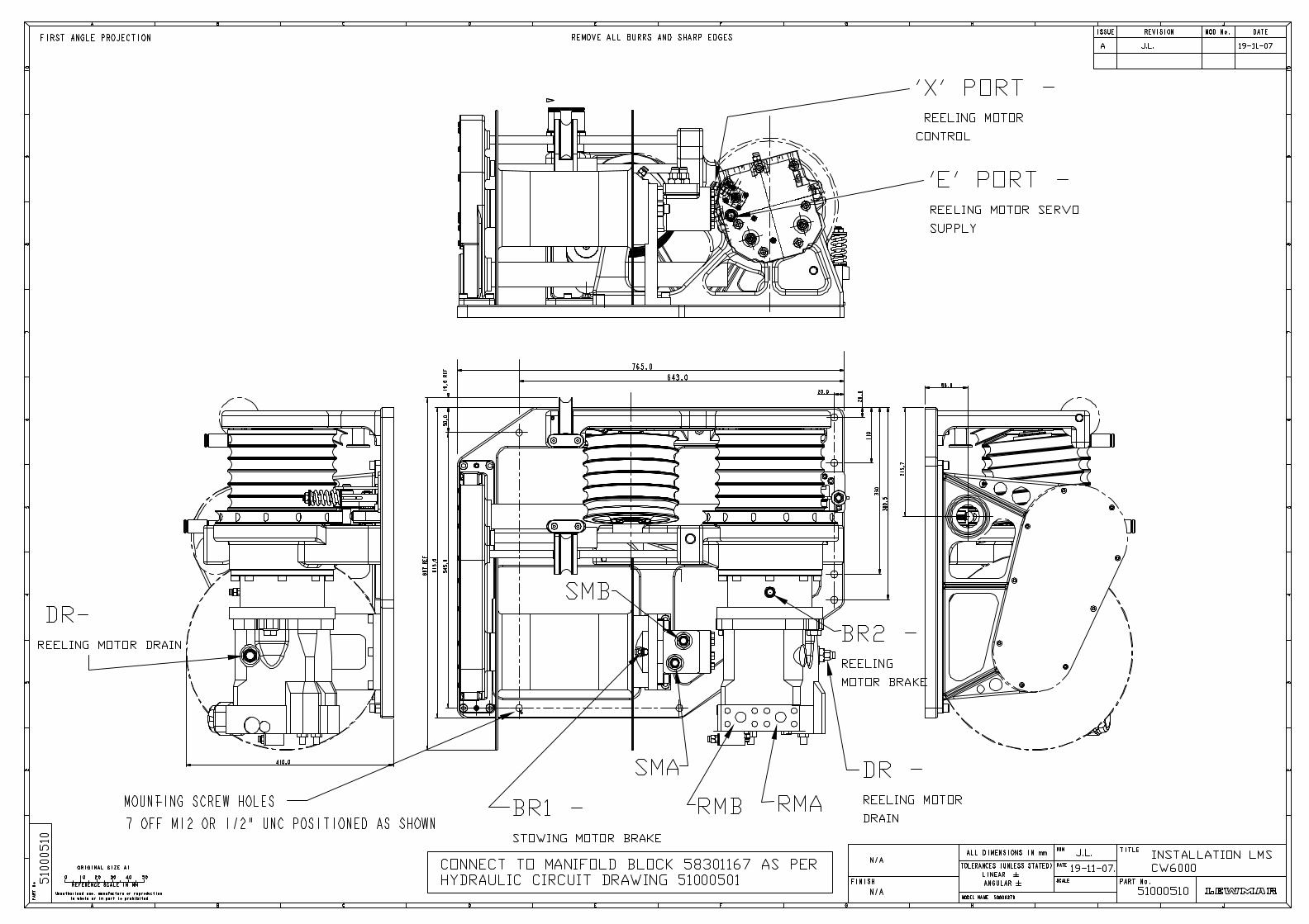
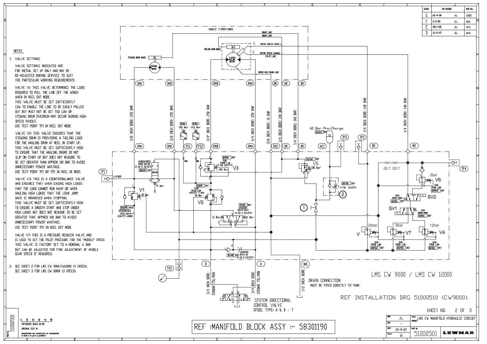
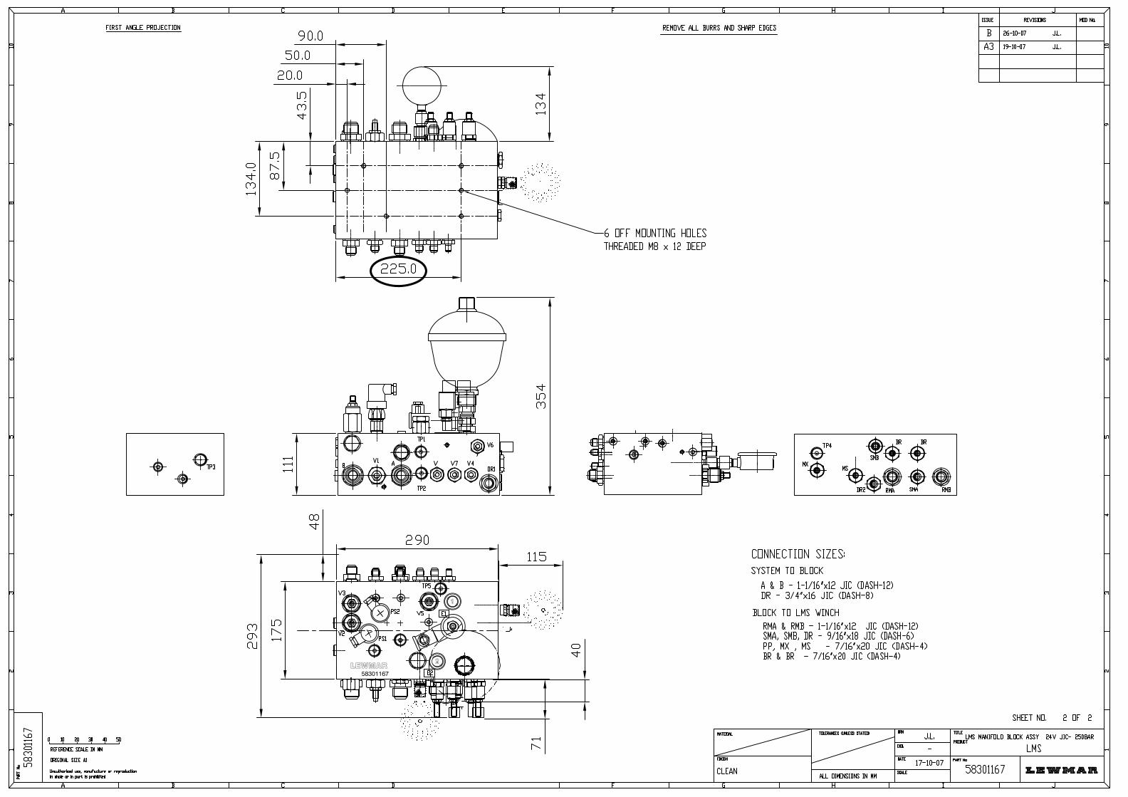
INSTALLATION UNPACKING Care must be taken when unpacking the LMS CW 6000 winch. If lifting tackle is used, ensure that it cannot inflict damage to the winch. When lifting, use a soft strop positioned around the base plate or the main hauling drum only (not the Carbon Fibre stowing drum), do not allow the lifting strop to contact any other part of the winch especially the ball reverser. Do not use wire rope for lifting. INSTALLATION Reference drawing No 59600270. A flat pad or area to suit the winch base plate must be provided. Ideally this pad should be flat to within 1 mm. The 10 x 12mm base bolts should be tightened to a torque of 40 to 45 lbf / ft (54 to 61 NM). A working area should be available around the winch to facilitate installation, hydraulic connections, and future maintenance see maintenance drawing for details. HYDRAULIC CONNECTIONS Reference drawing Nos. 51000501 (Hydraulic Circuit), & 51000510 (LMS Connections) The winch manifold block is supplied with male connections of JIC type, manifold block numbers are stamped on the top face for identification. All hose fittings are stamped with identifications relevant to the hydraulic installation drawing 51000501. Hose ends should be of the straight type or 90 degree swept (90 degree bent tube) type to minimise pressure drop loss. Avoid the use of 90-degree elbows or sharp bends - a minimum bend radius of 150 mm (6") is recommended. If the hose length is greater than approximately 7 m (20 ft) then a hose with a larger inside diameter should be used to minimise pressure drop loss. All hoses should be suitable for a safe working pressure of 250 Bar minimum. Wherever possible use hoses ends of the crimped or swaged type in preference to the reusable type. Connections "A" and "B" should be connected to the systems appropriate directional control valve ports or to the Lewmar Commander directional control valve "A" and "B" ports - refer to your Commander Manual to determine which of the functions has been allocated to operate the LMS CW 6000. The "Drain" connection should be routed directly into the reservoir tank drain fitting.
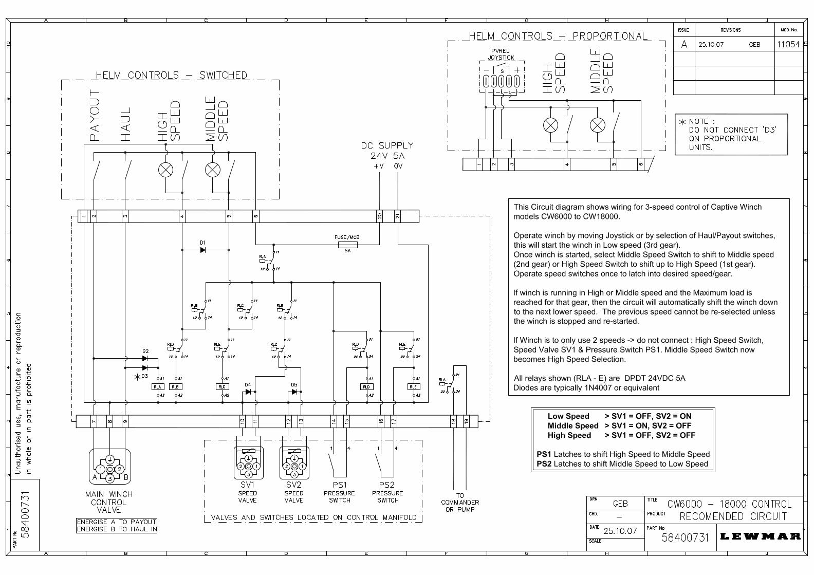
INSTALLATION *** IMPORTANT *** When connecting the hydraulic supply, cleanliness is of the utmost importance and the following notes should be observed: - Do not remove the protective caps on the winch hydraulic connections until absolutely necessary. Ensure hoses are flushed through to remove any contamination before connecting to the winch. It is generally acknowledged that over 80% of all hydraulic components failure can be attributed to contamination. ELECTRICAL CONNECTIONS Refer to drawing 58400731 for electrical wiring details FITTING THE LINE Each LMS CW 6000 Winch is assembled to suit a specific rope diameter agreed at the time of order. Ensure that the correct diameter rope is to be fitted. Important: Before fitting the rope, the Stowing Drum Ball Reverser Nut and Sheave Assembly must be correctly aligned. There are two methods of achieving this. Method 1 Rotate the stowing drum (by hydraulic power) until the Ball Reverser has traversed to the end of its travel at the end of the drum containing the Rope Stay or Rope Hole. Stop the drum rotation when the Ball Reverser just commences to move away from the end of its travel. This will ensure that the rope lies correctly on the drum and will prevent damage being incurred by the Ball Reverser.
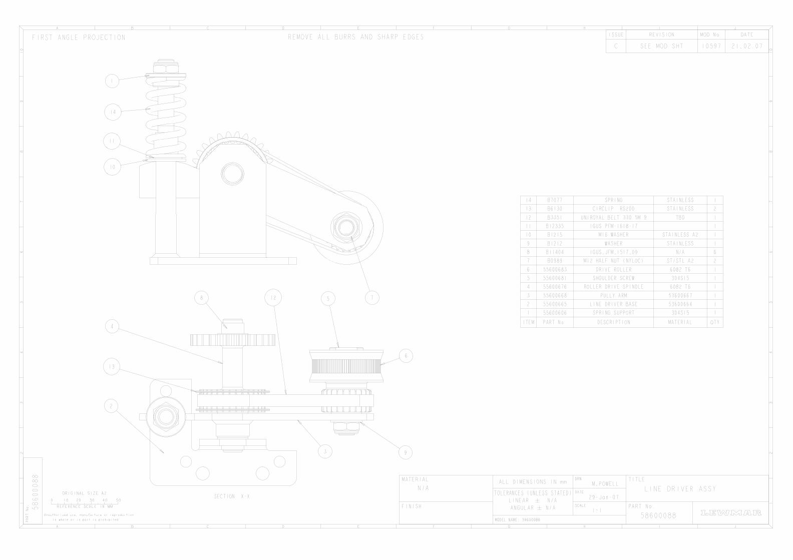
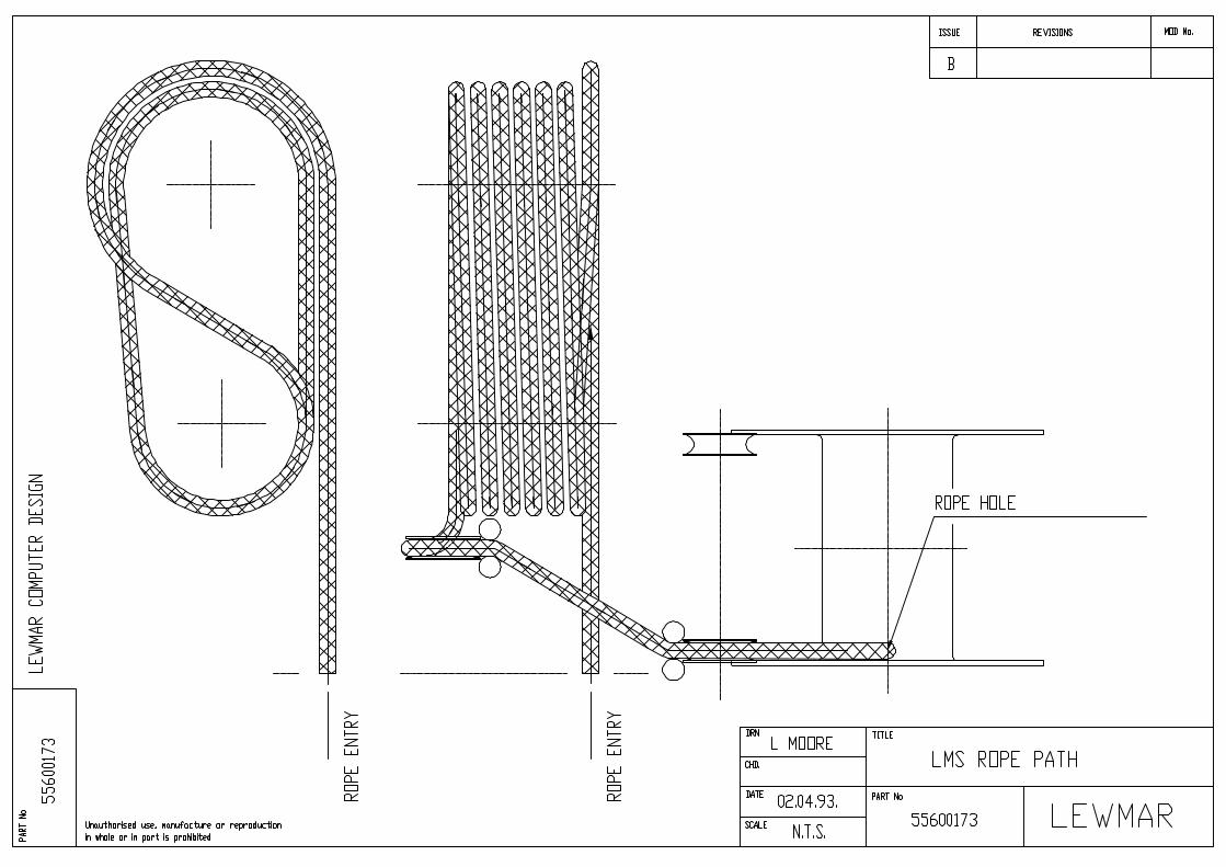
INSTALLATION FITTING THE LINE CONTINUED Method 2 Remove the Ball Reverser belt drive cover plate and slide the toothed belt off the Ball Reverser shaft pulley. Rotate the Ball Reverser shaft by hand until the Ball Reverser Nut and Sheave Assembly is just starting to move away from the stowing drum flange containing the Rope Stay or Rope Hole. Refit the Toothed Belt and Cover Plate. The rope may now be passed through the entry tube to the Drive Roller Assembly. Insert the rope between the small Drive Roller and the Large Roller. Slowly rotate the large drum by hand to feed the rope through ensuring that the rope is passed above the Small Drive Roller Spindle (i.e. between the spindle and the drum). The rope is then passed around the Idle drum and multi groove main drum and sheaves and is secured to the stowing drum by means of the rope stay and nut or pushed into the Rope Hole. Refer to drawing No 55600173 for the rope path. NOTE: The LMS CW 6000 Winch is fitted as standard with an automatic rope pay - out feature which drives the line off the winch irrespective of the line load when the Winch is in Reel Out Mode. If this feature is not required then the Drive Belt (B3351) should be removed. This can been seen on drawing no 58600088. NOTE: High Load Release Function is not affected by the presence or absence of the drive belt.
OPERATION CONTROL The LMS CW 6000 is fitted with a variable displacement motor which gives two or three speed control. The unit can be controlled by either On/Off button or Joystick control or Proportional Joystick. Different speeds are selected by depressing the High Speed or Middle Speed (if fitted buttons). Refer to electrical drawing 58400731 for control description. Moving the joystick will start the LMS CW 6000 in the direction selected i.e Haul or Payout. Selecting the High Speed button or Middle Speed Button (If fitted) will change the speed of the unit.
SERVICING AND MAINTENANCE The LMS CW 6000 Winch has been designed to provide long and trouble free operation, however as with all Electro-Hydraulic and Mechanical equipment, periodic service and maintenance is required to minimise the risk of unplanned down-time. Because the duty cycle of each installation can be very different, the time period between service checks and maintenance can be difficult to predict, however we would recommend the following: Regular cleaning of the Drive Roller Assembly to remove dust and fluff deposited from the rope. Periodic cleansing and re-greasing of the Stowing Drum Ball Reverser Screw and Nut Assembly. Lewmar recommend the use of Lewmar Multi Purpose Winch Grease (used sparingly). Periodically check the winch and associated pipe work for hydraulic leaks and inspect the hydraulic hoses for any signs of damage or chafing. At 12 monthly intervals we would recommend the following: Remove the Ball Reverser drive cover plate and inspect the Toothed Belt and replace if required. Check the tightness of the belt pulley central retaining screws. Inspect the Drive Roller Assembly Toothed Belt and replace if necessary. Check tightness of the Sheave guard central retaining screws (4 off). Check the electrical connections on the winch manifold, solenoid valves and pressure switch.
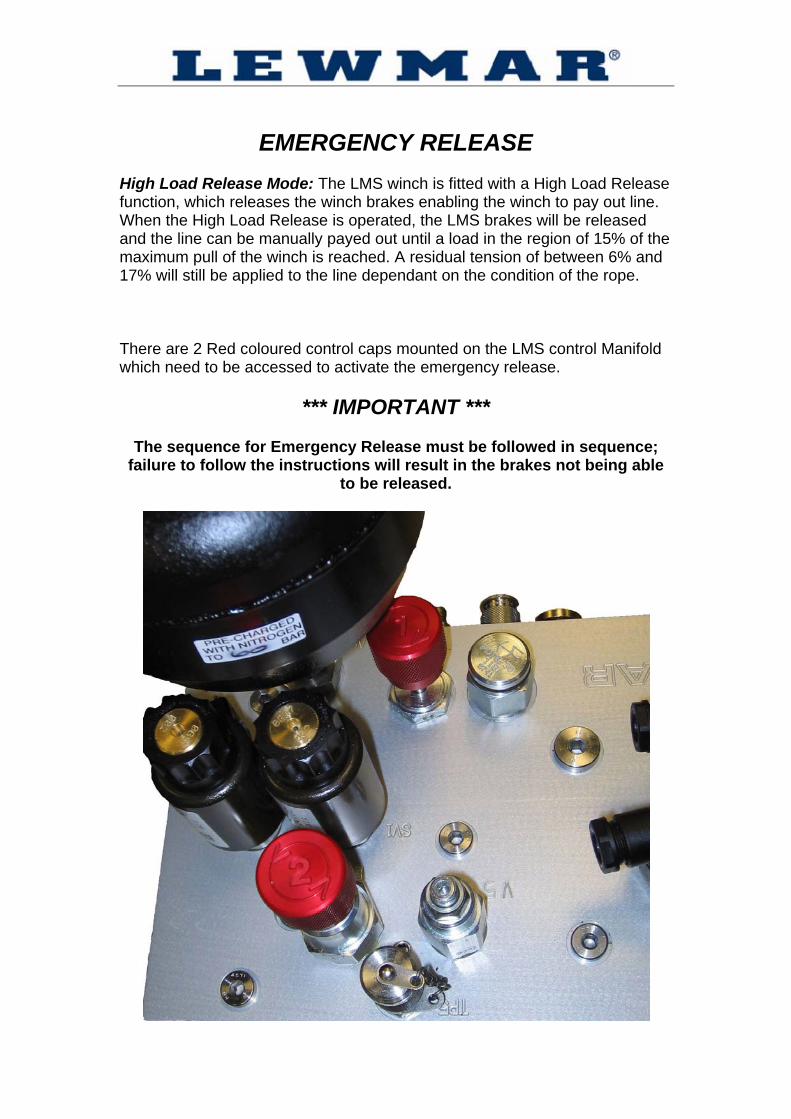
EMERGENCY RELEASE High Load Release Mode: The LMS winch is fitted with a High Load Release function, which releases the winch brakes enabling the winch to pay out line. When the High Load Release is operated, the LMS brakes will be released and the line can be manually payed out until a load in the region of 15% of the maximum pull of the winch is reached. A residual tension of between 6% and 17% will still be applied to the line dependant on the condition of the rope. There are 2 Red coloured control caps mounted on the LMS control Manifold which need to be accessed to activate the emergency release.
*** IMPORTANT ***
The sequence for Emergency Release must be followed in sequence; failure to follow the instructions will result in the brakes not being able
to be released.
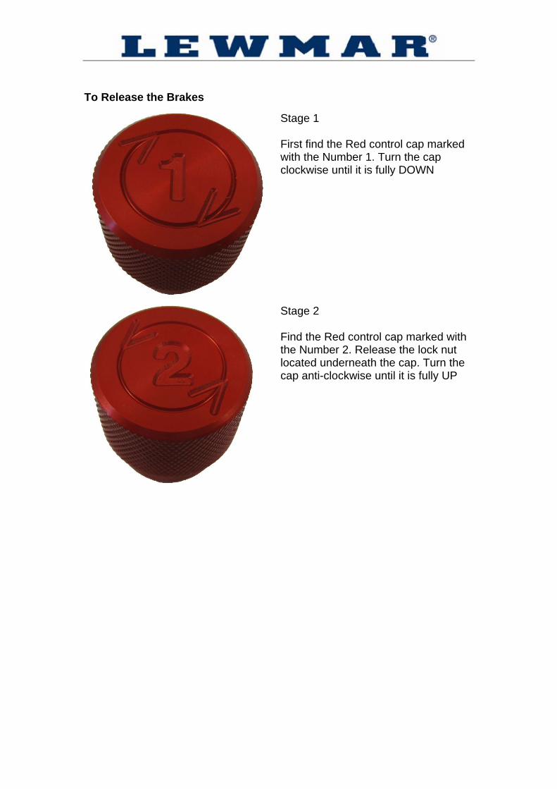
To Release the Brakes
Stage 1 First find the Red control cap marked with the Number 1. Turn the cap clockwise until it is fully DOWN
Stage 2 Find the Red control cap marked with the Number 2. Release the lock nut located underneath the cap. Turn the cap anti-clockwise until it is fully UP
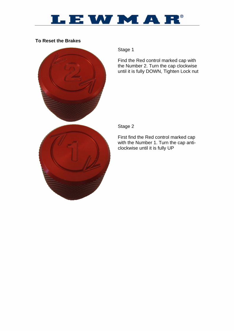
To Reset the Brakes
Stage 1 Find the Red control marked cap with the Number 2. Turn the cap clockwise until it is fully DOWN, Tighten Lock nut
Stage 2 First find the Red control marked cap with the Number 1. Turn the cap anti-clockwise until it is fully UP

NOTES

NOTES

NOTES
LIMITED WARRANTY and KEY TERMS OF SUPPLY BY LEWMAR Lewmar warrants that in normal usage and with proper maintenance its products will conform with their specification for a period of three years from the date of purchase by the end user, subject to the conditions, limitations and exceptions listed below. Any product, which proves to be defective in normal usage during that three-year period, will be repaired or, at Lewmar’s option, replaced by Lewmar. A CONDITIONS AND LIMITATIONS
i Lewmar’s liability shall be limited to the repair or replacement of any parts of the product which are defective in materials or workmanship.
ii Responsibility for the selection of products appropriate for the use
intended by the Buyer shall rest solely with the Buyer and Lewmar accepts no responsibility for any such selection.
iii Lewmar shall not be liable in any way for Product failure, or any
resulting loss or damage which arises from:
a use of a product in an application for which it was not designed or intended;
b. corrosion, ultra violet degradation or wear and tear; c. a failure to service or maintain the product in accordance with
Lewmar's recommendations;
d. faulty or deficient installation of the product (unless conducted by Lewmar);
e. any modification or alteration of the product; f. conditions that exceed the product’s performance specifications
or safe working loads.
iv Product subject to a warranty claim must be returned to the Lewmar outlet which supplied the product for examination unless otherwise agreed by Lewmar in writing.
v This warranty does not cover any incidental costs incurred for the
investigation, removal, carriage, transport or installation of product. vi Service by anyone other than authorised Lewmar representatives shall
void this warranty unless it accords with Lewmar guidelines and standards of workmanship.
vii Lewmar’s products are intended for use only in the marine
environment. Buyers intending to use them for any other purpose should seek independent professional advice as to their suitability. Lewmar accepts no liability arising from such other use.
B EXCEPTIONS
Cover under this Warranty is limited to a period of one year from the date of purchase by the end user in the case of any of the following products or parts of products:
- Electric motors and associated electrical equipment - Electronic controls - Hydraulic pumps, valves and actuators - Weather seals
- Products used in “Grand Prix” racing applications
C LIABILITY
i Lewmar's liability under this warranty shall be to the exclusion of all other warranties or liabilities (to the extent permitted by law). In particular (but without limitation): a Lewmar shall not be liable for: - Any loss of anticipated turnover or profit or indirect,
consequential or economic loss ; - Damages, costs or expenses payable to any third party; - Any damage to yachts or equipment; - Death or personal Injury (unless caused by Lewmar's
negligence). Some states and countries do not allow the exclusion or limitation of incidental or consequential damages, so the above limitation or exclusion may not apply to you.
b Lewmar grants no other warranties regarding the fitness for
purpose, use, nature or satisfactory quality of the products.
ii Where applicable law does not permit a statutory or implied warranty to be excluded, then such warranty, if permitted by that state or country's law, shall be limited to a period of one year from the date of purchase by the end user. Some states and countries do not allow limitations on how long an implied warranty lasts, so this limitation may not apply to you.
D PROCEDURE Notice of a claim for service under this warranty shall be made promptly and in writing by the end user to the Lewmar outlet which supplied the product or to Lewmar at Southmoor Lane, Havant, Hampshire, England PO9 1JJ.
E SEVERANCE CLAUSE If any clause of this warranty is held by any court or other competent authority to be invalid or unenforceable in whole or in part, the validity of the remaining clauses of this warranty and the remainder of the clause in question shall not be affected.
F OTHER RIGHTS This warranty gives you specific legal rights, and you may also have other legal rights, which vary, from state to state and country to country. In the case of European States a Consumer customer (as defined nationally) has legal rights under the applicable national law governing the sale of Consumer Goods; this Warranty does not affect those rights. G LAW This warranty shall be governed by and read in accordance with the laws of England or the state or country in which the first end user is domiciled at the time of purchase of the product. H DISPUTES Any dispute arising under this warranty may, at the option of the end-user, be referred to alternative dispute resolution under the rules of the British Marine Federation or to the Courts of the State whose law shall govern the warranty or to the Courts of England and Wales. The British Marine Federation may be contacted at Marine House, Thorpe Lea Road, Egham, England, TW20 8BF
UK & International Distribution Southmoor Lane, Havant
Hampshire PO9 1JJ England
Tel: +44 (0)23 9247 1841 Fax: +44 (0)23 9248 5720
Email: [email protected]
USA 351 New Whitfield Street
Guilford, CT 06437 USA
Tel: +1 203 458 6200 Fax: +1 203 453 5669
Email: [email protected]
Northern Europe Popovstraat 12
8013 RK Zwolle
Netherlands
Tel: +31 (0)38 427 34 90 Fax: +31 (0)38 421 56 42
Email: [email protected]
Southern Europe 18 rue Leonard de Vinci Z.A.C Belle Aire Nord
17440 Aytre France
Tel: +33 5 46 50 50 46 Fax: +33 5 46 50 59 04
Email: [email protected]
Australia Unit 4, 224 Headland Road
Dee Why 2099, NSW Australia
Tel: +61 29 936 7111 Fax: +61 29936 7112
Email: [email protected]