cx600 x1 mcx600 x2 mv800r005c01configurationguide interfaceanddatalink03pdf 140820131824 phpapp02
TRANSCRIPT
8/18/2019 Cx600 x1 Mcx600 x2 Mv800r005c01configurationguide Interfaceanddatalink03pdf 140820131824 Phpapp02
http://slidepdf.com/reader/full/cx600-x1-mcx600-x2-mv800r005c01configurationguide-interfaceanddatalink03pdf 1/42
HUAWEI CX600-X1-M/CX600-X2-M Series Metro
Services Platform
V800R005C01
Configuration Guide - Interface and
Data Link
Issue 03
Date 2014-04-30
HUAWEI TECHNOLOGIES CO., LTD.
8/18/2019 Cx600 x1 Mcx600 x2 Mv800r005c01configurationguide Interfaceanddatalink03pdf 140820131824 Phpapp02
http://slidepdf.com/reader/full/cx600-x1-mcx600-x2-mv800r005c01configurationguide-interfaceanddatalink03pdf 2/42
Copyright © Huawei Technologies Co., Ltd. 2014. All rights reserved.
No part of this document may be reproduced or transmitted in any form or by any means without prior written
consent of Huawei Technologies Co., Ltd.
Trademarks and Permissions
and other Huawei trademarks are trademarks of Huawei Technologies Co., Ltd.
All other trademarks and trade names mentioned in this document are the property of their respective holders.
Notice
The purchased products, services and features are stipulated by the contract made between Huawei and the
customer. All or part of the products, services and features described in this document may not be within the
purchase scope or the usage scope. Unless otherwise specified in the contract, all statements, information,
and recommendations in this document are provided "AS IS" without warranties, guarantees or representations
of any kind, either express or implied.
The information in this document is subject to change without notice. Every effort has been made in the
preparation of this document to ensure accuracy of the contents, but all statements, information, and
recommendations in this document do not constitute a warranty of any kind, express or implied.
Huawei Technologies Co., Ltd.
Address: Huawei Industrial Base
Bantian, Longgang
Shenzhen 518129
People's Republic of China
Website: http://www.huawei.com
Email: [email protected]
Issue 03 (2014-04-30) Huawei Proprietary and Confidential
Copyright © Huawei Technologies Co., Ltd.
i
8/18/2019 Cx600 x1 Mcx600 x2 Mv800r005c01configurationguide Interfaceanddatalink03pdf 140820131824 Phpapp02
http://slidepdf.com/reader/full/cx600-x1-mcx600-x2-mv800r005c01configurationguide-interfaceanddatalink03pdf 3/42
About This Document
Purpose
This document provides the basic concepts, configuration procedures, and configuration
examples in different application scenarios of the Interface Management feature supported by
the CX600 device.
NOTICE
Note the following precautions:
l Currently, the device supports the AES and SHA2 encryption algorithms. AES is reversible,
while SHA2 is irreversible. A protocol interworking password must be reversible, and a local
administrator password must be irreversible.
l If the plain parameter is specified, the password will be saved in plaintext in the configuration
file, which has a high security risk. Therefore, specifying the cipher parameter is
recommended. To further improve device security, periodically change the password.
l Do not set both the start and end characters of a password to "%$%$." This causes the
password to be displayed directly in the configuration file.
Related Version
The following table lists the product version related to this document.
Product Name Version
CX600 V800R005C01
U2000 V100R009C00
Intended Audience
This document is intended for:
HUAWEI CX600-X1-M/CX600-X2-M Series Metro
Services Platform
Configuration Guide - Interface and Data Link About This Document
Issue 03 (2014-04-30) Huawei Proprietary and Confidential
Copyright © Huawei Technologies Co., Ltd.
ii
8/18/2019 Cx600 x1 Mcx600 x2 Mv800r005c01configurationguide Interfaceanddatalink03pdf 140820131824 Phpapp02
http://slidepdf.com/reader/full/cx600-x1-mcx600-x2-mv800r005c01configurationguide-interfaceanddatalink03pdf 4/42
l Data configuration engineers
l Commissioning engineers
l Network monitoring engineers
l
System maintenance engineers
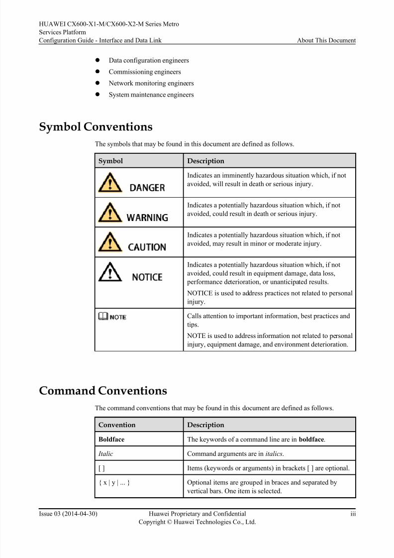
Symbol Conventions
The symbols that may be found in this document are defined as follows.
Symbol Description
Indicates an imminently hazardous situation which, if not
avoided, will result in death or serious injury.
Indicates a potentially hazardous situation which, if not
avoided, could result in death or serious injury.
Indicates a potentially hazardous situation which, if not
avoided, may result in minor or moderate injury.
Indicates a potentially hazardous situation which, if not
avoided, could result in equipment damage, data loss,
performance deterioration, or unanticipated results.
NOTICE is used to address practices not related to personalinjury.
Calls attention to important information, best practices and
tips.
NOTE is used to address information not related to personal
injury, equipment damage, and environment deterioration.
Command ConventionsThe command conventions that may be found in this document are defined as follows.
Convention Description
Boldface The keywords of a command line are in boldface.
Italic Command arguments are in italics.
[ ] Items (keywords or arguments) in brackets [ ] are optional.
{ x | y | ... } Optional items are grouped in braces and separated by
vertical bars. One item is selected.
HUAWEI CX600-X1-M/CX600-X2-M Series Metro
Services Platform
Configuration Guide - Interface and Data Link About This Document
Issue 03 (2014-04-30) Huawei Proprietary and Confidential
Copyright © Huawei Technologies Co., Ltd.
iii
8/18/2019 Cx600 x1 Mcx600 x2 Mv800r005c01configurationguide Interfaceanddatalink03pdf 140820131824 Phpapp02
http://slidepdf.com/reader/full/cx600-x1-mcx600-x2-mv800r005c01configurationguide-interfaceanddatalink03pdf 5/42
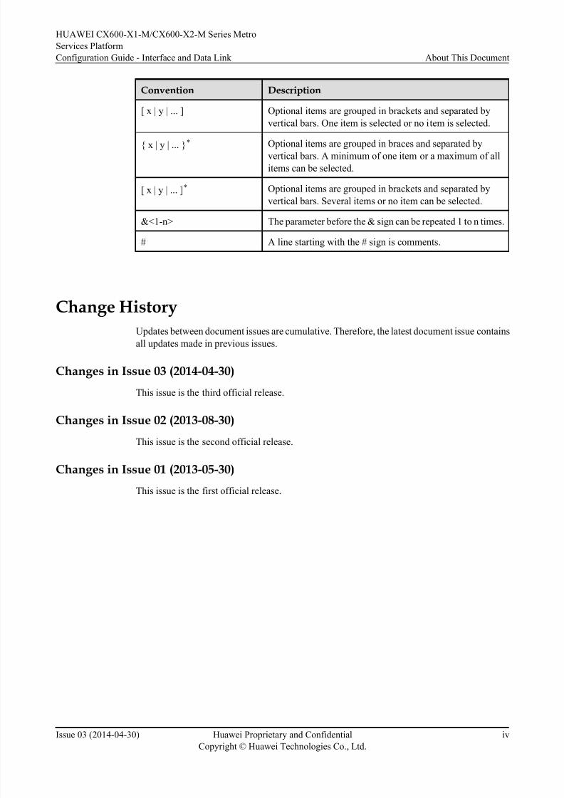
Convention Description
[ x | y | ... ] Optional items are grouped in brackets and separated by
vertical bars. One item is selected or no item is selected.
{ x | y | ... }* Optional items are grouped in braces and separated by
vertical bars. A minimum of one item or a maximum of all
items can be selected.
[ x | y | ... ]* Optional items are grouped in brackets and separated by
vertical bars. Several items or no item can be selected.
&<1-n> The parameter before the & sign can be repeated 1 to n times.
# A line starting with the # sign is comments.
Change History
Updates between document issues are cumulative. Therefore, the latest document issue contains
all updates made in previous issues.
Changes in Issue 03 (2014-04-30)
This issue is the third official release.
Changes in Issue 02 (2013-08-30)
This issue is the second official release.
Changes in Issue 01 (2013-05-30)
This issue is the first official release.
HUAWEI CX600-X1-M/CX600-X2-M Series Metro
Services Platform
Configuration Guide - Interface and Data Link About This Document
Issue 03 (2014-04-30) Huawei Proprietary and Confidential
Copyright © Huawei Technologies Co., Ltd.
iv

8/18/2019 Cx600 x1 Mcx600 x2 Mv800r005c01configurationguide Interfaceanddatalink03pdf 140820131824 Phpapp02
http://slidepdf.com/reader/full/cx600-x1-mcx600-x2-mv800r005c01configurationguide-interfaceanddatalink03pdf 6/42
Contents
About This Document.....................................................................................................................ii
1 Interface Management..................................................................................................................1
1.1 Overview........................................................................................................................................................................3
1.2 Interfaces Supported on the CX600................................................................................................................................51.3 Board Working Modes and Service Interface Numbering Rules...................................................................................7
1.4 Performing Basic Configurations on an Interface........................................................................................................11
1.4.1 Entering the Interface View.......................................................................................................................................12
1.4.2 (Optional) Setting Interface Parameters....................................................................................................................12
1.4.3 Enabling an Interface.................................................................................................................................................15
1.4.4 (Optional) Configuring a Device to Send a Trap Message to an NMS When an Interface Physical Status Changes
............................................................................................................................................................................................16
1.4.5 Configuring IPv4 and IPv6 Traffic Statistics on The Main Interface.......................................................................17
1.4.6 Checking the Configurations.....................................................................................................................................17
1.5 Configuring the Physical Link Detection Function......................................................................................................19
1.5.1 Enabling the Alarm Function on Interfaces...............................................................................................................19
1.5.2 Configuring Alarm Thresholds and Intervals on Interfaces......................................................................................20
1.5.3 (Optional) Enabling the Function to Shut Down the Associated Physical Port When an Alarm Is Reported..........23
1.5.4 Checking the Configuration.......................................................................................................................................24
1.6 Configuring the Control-Flap Function........................................................................................................................26
1.7 Enabling the Signal Sending Delay Function...............................................................................................................27
1.8 Configuring an Interface Monitoring Group................................................................................................................28
1.9 Configuring Logical Interfaces.....................................................................................................................................31
1.9.1 Creating a Loopback Interface and Configuring Its IP Address................................................................................33
1.9.2 Entering the NULL Interface View...........................................................................................................................33
1.9.3 Checking the Configuration.......................................................................................................................................34
1.10 Configuration Examples.............................................................................................................................................35
1.10.1 Example for Managing Interfaces...........................................................................................................................35
HUAWEI CX600-X1-M/CX600-X2-M Series Metro
Services Platform
Configuration Guide - Interface and Data Link Contents
Issue 03 (2014-04-30) Huawei Proprietary and Confidential
Copyright © Huawei Technologies Co., Ltd.
v
8/18/2019 Cx600 x1 Mcx600 x2 Mv800r005c01configurationguide Interfaceanddatalink03pdf 140820131824 Phpapp02
http://slidepdf.com/reader/full/cx600-x1-mcx600-x2-mv800r005c01configurationguide-interfaceanddatalink03pdf 7/42
1 Interface Management
About This Chapter
Interface management helps to provide quick and accurate communication between devices.
1.1 Overview
This section provides the physical and logical interfaces supported by the CX600 and describes
the interface views and prompts and common link protocols and access technologies.
1.2 Interfaces Supported on the CX600
This section describes the physical and logical interfaces supported on the CX600.
1.3 Board Working Modes and Service Interface Numbering RulesThis section describes the board working modes of the CX600-X2-M8, CX600-X2-M16 and
service interf ace numbering rules of the CX600-X1-M4, CX600-X2-M8 and CX600-X2-M16.
1.4 Performing Basic Configurations on an Interface
This section describes how to perform basic configurations on an interface. The basic
configurations involve interface types and configurable interface parameters, which enable easy
interface management.
1.5 Configuring the Physical Link Detection Function
The physical link detection function helps reduce the number of alarms generated on links and
avoids system performance degradation caused by plenty of alarms that would be otherwise
generated.
1.6 Configuring the Control-Flap Function
This section describes how to configure the control-flap function.
1.7 Enabling the Signal Sending Delay Function
This section describes how to configure the signal sending delay function.
1.8 Configuring an Interface Monitoring Group
In a dual-device backup scenario, you can configure an interface monitoring group to allow the
user-side interface status to change with the network-side interface status so that traffic can be
switched between the master and backup links.
1.9 Configuring Logical Interfaces
HUAWEI CX600-X1-M/CX600-X2-M Series Metro
Services Platform
Configuration Guide - Interface and Data Link 1 Interface Management
Issue 03 (2014-04-30) Huawei Proprietary and Confidential
Copyright © Huawei Technologies Co., Ltd.
1

8/18/2019 Cx600 x1 Mcx600 x2 Mv800r005c01configurationguide Interfaceanddatalink03pdf 140820131824 Phpapp02
http://slidepdf.com/reader/full/cx600-x1-mcx600-x2-mv800r005c01configurationguide-interfaceanddatalink03pdf 8/42
This section describes how to configure logical interfaces. Logical interfaces are manually
configured interfaces, which are used to exchange data. Logical interfaces do not exist
physically.
1.10 Configuration Examples
This section provides interface management examples.
HUAWEI CX600-X1-M/CX600-X2-M Series Metro
Services Platform
Configuration Guide - Interface and Data Link 1 Interface Management
Issue 03 (2014-04-30) Huawei Proprietary and Confidential
Copyright © Huawei Technologies Co., Ltd.
2
8/18/2019 Cx600 x1 Mcx600 x2 Mv800r005c01configurationguide Interfaceanddatalink03pdf 140820131824 Phpapp02
http://slidepdf.com/reader/full/cx600-x1-mcx600-x2-mv800r005c01configurationguide-interfaceanddatalink03pdf 9/42
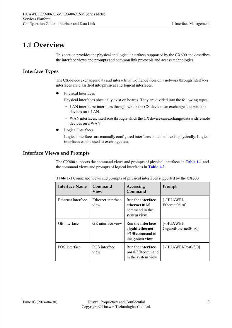
1.1 Overview
This section provides the physical and logical interfaces supported by the CX600 and describes
the interface views and prompts and common link protocols and access technologies.
Interface Types
The CX device exchanges data and interacts with other devices on a network through interfaces.
interfaces are classified into physical and logical interfaces.
l Physical Interfaces
Physical interfaces physically exist on boards. They are divided into the following types:
– LAN interfaces: interfaces through which the CX device can exchange data with the
devices on a LAN.
– WAN interfaces: interfaces through which the CX device can exchange data with remote
devices on a WAN.
l Logical Interfaces
Logical interfaces are manually configured interfaces that do not exist physically. Logical
interfaces can be used to exchange data.
Interface Views and Prompts
The CX600 supports the command views and prompts of physical interfaces in Table 1-1 and
the command views and prompts of logical interfaces in Table 1-2.
Table 1-1 Command views and prompts of physical interfaces supported by the CX600
Interface Name CommandView
Accessing Command
Prompt
Ethernet interface Ethernet interface
view
Run the interface
ethernet 0/1/0
command in the
system view.
[~HUAWEI-
Ethernet0/1/0]
GE interface GE interface view Run the interface
gigabitethernet0/1/0 command in
the system view
[~HUAWEI-
GigabitEthernet0/1/0]
POS interface POS interface
view
Run the interface
pos 0/3/0 command
in the system view
[~HUAWEI-Pos0/3/0]
HUAWEI CX600-X1-M/CX600-X2-M Series Metro
Services Platform
Configuration Guide - Interface and Data Link 1 Interface Management
Issue 03 (2014-04-30) Huawei Proprietary and Confidential
Copyright © Huawei Technologies Co., Ltd.
3
8/18/2019 Cx600 x1 Mcx600 x2 Mv800r005c01configurationguide Interfaceanddatalink03pdf 140820131824 Phpapp02
http://slidepdf.com/reader/full/cx600-x1-mcx600-x2-mv800r005c01configurationguide-interfaceanddatalink03pdf 10/42
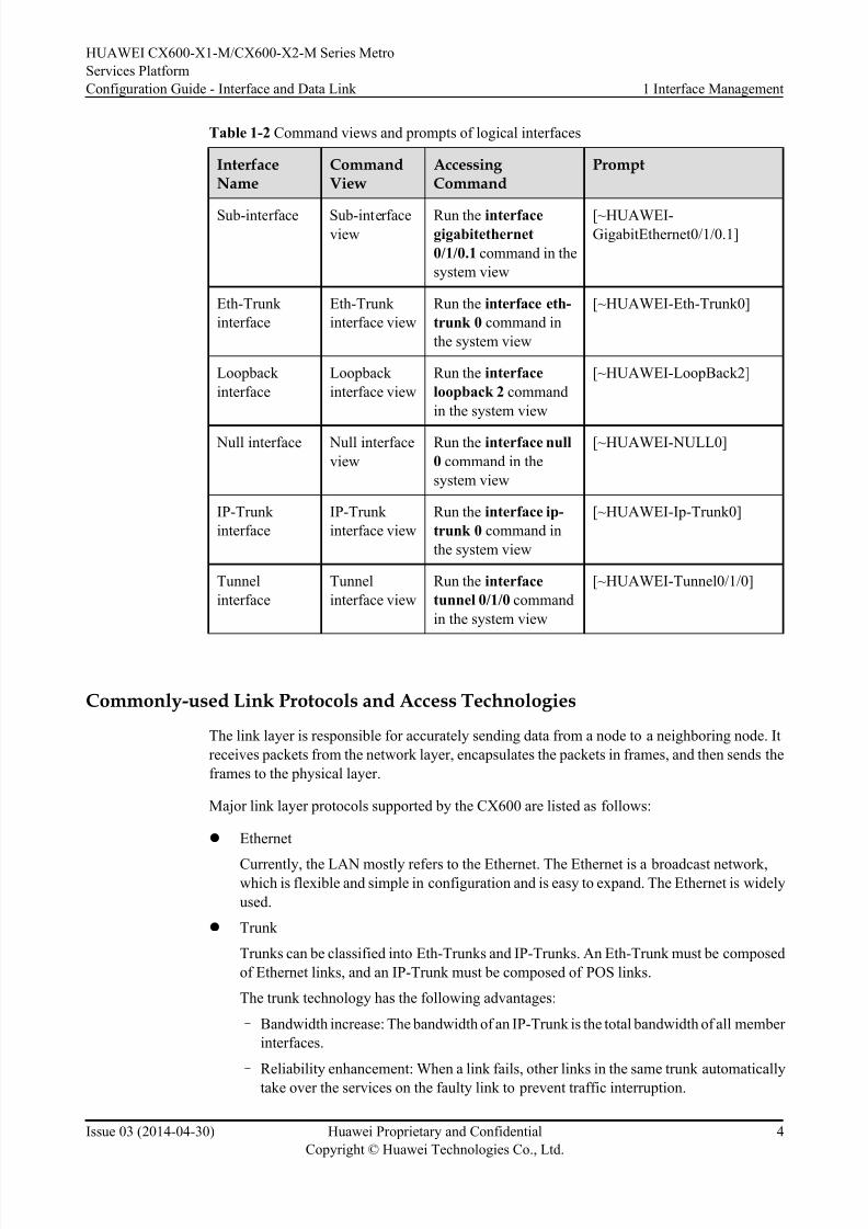
Table 1-2 Command views and prompts of logical interfaces
InterfaceName
CommandView
Accessing Command
Prompt
Sub-interface Sub-interfaceview
Run the interfacegigabitethernet
0/1/0.1 command in the
system view
[~HUAWEI-GigabitEthernet0/1/0.1]
Eth-Trunk
interface
Eth-Trunk
interface view
Run the interface eth-
trunk 0 command in
the system view
[~HUAWEI-Eth-Trunk0]
Loopback
interface
Loopback
interface view
Run the interface
loopback 2 command
in the system view
[~HUAWEI-LoopBack2]
Null interface Null interface
view
Run the interface null
0 command in the
system view
[~HUAWEI-NULL0]
IP-Trunk
interface
IP-Trunk
interface view
Run the interface ip-
trunk 0 command in
the system view
[~HUAWEI-Ip-Trunk0]
Tunnel
interface
Tunnel
interface view
Run the interface
tunnel 0/1/0 command
in the system view
[~HUAWEI-Tunnel0/1/0]
Commonly-used Link Protocols and Access Technologies
The link layer is responsible for accurately sending data from a node to a neighboring node. It
receives packets from the network layer, encapsulates the packets in frames, and then sends the
frames to the physical layer.
Major link layer protocols supported by the CX600 are listed as follows:
l Ethernet
Currently, the LAN mostly refers to the Ethernet. The Ethernet is a broadcast network,which is flexible and simple in configuration and is easy to expand. The Ethernet is widely
used.
l Trunk
Trunks can be classified into Eth-Trunks and IP-Trunks. An Eth-Trunk must be composed
of Ethernet links, and an IP-Trunk must be composed of POS links.
The trunk technology has the following advantages:
– Bandwidth increase: The bandwidth of an IP-Trunk is the total bandwidth of all member
interfaces.
– Reliability enhancement: When a link fails, other links in the same trunk automatically
take over the services on the faulty link to prevent traffic interruption.
HUAWEI CX600-X1-M/CX600-X2-M Series Metro
Services Platform
Configuration Guide - Interface and Data Link 1 Interface Management
Issue 03 (2014-04-30) Huawei Proprietary and Confidential
Copyright © Huawei Technologies Co., Ltd.
4
8/18/2019 Cx600 x1 Mcx600 x2 Mv800r005c01configurationguide Interfaceanddatalink03pdf 140820131824 Phpapp02
http://slidepdf.com/reader/full/cx600-x1-mcx600-x2-mv800r005c01configurationguide-interfaceanddatalink03pdf 11/42
l PPP
The Point-to-Point Protocol (PPP) is used to encapsulate IP packets on serial links. It
supports both the asynchronous transmission of 8-bit data without the parity check and the
bit-oriented synchronous connection.
PPP consists of the Link Control Protocol (LCP) and the Network Control Protocol (NCP).
LCP is used to create, configure, and test links; NCP is used to control different network
layer protocols.
l HDLC
The High-Level Data Link Control (HDLC) is a suite of protocols that are used to transmit
data between network nodes. HDLC is widely used at the data link layer.
In HDLC, the receiver responds with an acknowledgement when it receives frames
transmitted over the network. In addition, HDLC manages data flows and the interval at
which data packets are transmitted.
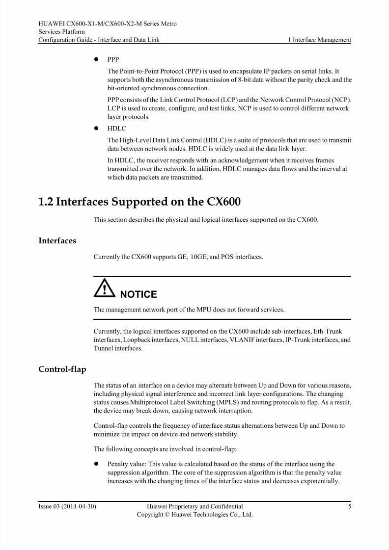
1.2 Interfaces Supported on the CX600
This section describes the physical and logical interfaces supported on the CX600.
Interfaces
Currently the CX600 supports GE, 10GE, and POS interfaces.
NOTICE
The management network port of the MPU does not forward services.
Currently, the logical interfaces supported on the CX600 include sub-interfaces, Eth-Trunk
interfaces, Loopback interfaces, NULL interfaces, VLANIF interfaces, IP-Trunk interfaces, and
Tunnel interfaces.
Control-flap
The status of an interface on a device may alternate between Up and Down for various reasons,including physical signal interference and incorrect link layer configurations. The changing
status causes Multiprotocol Label Switching (MPLS) and routing protocols to flap. As a result,
the device may break down, causing network interruption.
Control-flap controls the frequency of interface status alternations between Up and Down to
minimize the impact on device and network stability.
The following concepts are involved in control-flap:
l Penalty value: This value is calculated based on the status of the interface using the
suppression algorithm. The core of the suppression algorithm is that the penalty value
increases with the changing times of the interface status and decreases exponentially.
HUAWEI CX600-X1-M/CX600-X2-M Series Metro
Services Platform
Configuration Guide - Interface and Data Link 1 Interface Management
Issue 03 (2014-04-30) Huawei Proprietary and Confidential
Copyright © Huawei Technologies Co., Ltd.
5

8/18/2019 Cx600 x1 Mcx600 x2 Mv800r005c01configurationguide Interfaceanddatalink03pdf 140820131824 Phpapp02
http://slidepdf.com/reader/full/cx600-x1-mcx600-x2-mv800r005c01configurationguide-interfaceanddatalink03pdf 12/42
l Suppression threshold: The interface is suppressed when the penalty value is greater than
the suppression threshold. The suppression threshold must be greater than the reuse
threshold and smaller than the ceiling threshold.
l Reuse threshold: The interface is no longer suppressed when the penalty value is smaller
than the reuse threshold. The reuse threshold must be smaller than the suppressionthreshold.
l Ceiling threshold: The penalty value no longer increases when the penalty value reaches
the ceiling threshold. The ceiling threshold must be greater than the suppression threshold.
You can set the preceding parameters on the CX600 to restrict the frequency at which an interface
can alternate between Up and Down.
Figure 1-1 shows the relationships between these parameters.
Figure 1-1 Flapping control
t1 t2 t3 t4 t5
Penalty Valueceiling
suppress
reuse
timet6
Interface Monitoring Group
Network-side interfaces can be added to an interface monitoring group. Each interface
monitoring group is identified by a unique group name. The network-side interface to be
monitored is a binding interface, and the user-side interface associated with the group is a track
interface, whose status changes with the binding interface status. The interface monitoring group
monitors the status of all binding interfaces. When a specific proportion of binding interfaces
goes Down, the track interface associated with the interface monitoring group goes Down, which
causes traffic to be switched from the master link to the backup link. When the number of Down
binding interf aces falls below a specific threshold, the track interface goes Up, and traffic is
switched back to the master link.
HUAWEI CX600-X1-M/CX600-X2-M Series Metro
Services Platform
Configuration Guide - Interface and Data Link 1 Interface Management
Issue 03 (2014-04-30) Huawei Proprietary and Confidential
Copyright © Huawei Technologies Co., Ltd.
6

8/18/2019 Cx600 x1 Mcx600 x2 Mv800r005c01configurationguide Interfaceanddatalink03pdf 140820131824 Phpapp02
http://slidepdf.com/reader/full/cx600-x1-mcx600-x2-mv800r005c01configurationguide-interfaceanddatalink03pdf 13/42
1.3 Board Working Modes and Service Interface Numbering
RulesThis section describes the board working modes of the CX600-X2-M8, CX600-X2-M16 and
service interface numbering rules of the CX600-X1-M4, CX600-X2-M8 and CX600-X2-M16.
Board Working Modes Supported by the CX600-X2-M8
The CX600-X2-M8 supports the master/slave and load balancing working modes for NPUs.
l Master/slave
– In master/slave mode, the master NPU forwards services of all subcards, and the slave
NPU is a hot standby backup. The slave NPU takes over the services only when the
master NPU is unavailable, for example, when the master NPU fails or restarts. This
implementation prevents service interruptions when the master NPU is unavailable.
– In master/slave mode, each NPU manages all the eight subcards, PICs 1 to 8 in Figure
1-2.
l Load balancing
– In load balancing mode, two NPUs forward services of their managed subcards
respectively to load balance the total traffic of all subcards. If one NPU is unavailable,
the other NPU will not take over services on the unavailable NPU. Therefore, the load
balancing mode is less reliable than the master/slave mode.
–
In load balancing mode, each NPU manages only the subcards in the same half boardcage as the NPU itself. For example, in the board layout shown in Figure 1-2, NPU 9
manages PICs 1 to 4, and NPU 10 manages PICs 5 to 8. If NPU 10 is unavailable,
NPU 9 will not take over the services of PICs 5 to 8.
Figure 1-2 CX600-X2-M8 board layout
15
FAN
13 PSU 14 PSU
7 PIC 8 PIC
6 PIC5 PIC
10 NPU
9 NPU
3 PIC 4 PIC
2 PIC1 PIC
11 MPU 12 MPU
HUAWEI CX600-X1-M/CX600-X2-M Series Metro
Services Platform
Configuration Guide - Interface and Data Link 1 Interface Management
Issue 03 (2014-04-30) Huawei Proprietary and Confidential
Copyright © Huawei Technologies Co., Ltd.
7

8/18/2019 Cx600 x1 Mcx600 x2 Mv800r005c01configurationguide Interfaceanddatalink03pdf 140820131824 Phpapp02
http://slidepdf.com/reader/full/cx600-x1-mcx600-x2-mv800r005c01configurationguide-interfaceanddatalink03pdf 14/42
Board Working Modes Supported by the CX600-X2-M16
The CX600-X2-M16 supports the master/slave and load balancing working modes for NPUs.
l Master/slave
– In master/slave mode, the master NPU forwards services of all subcards, and the slave
NPU is a hot standby backup. The slave NPU takes over the services only when the
master NPU is unavailable, for example, when the master NPU fails or restarts. This
implementation prevents service interruptions when the master NPU is unavailable.
– In master/slave mode, each NPU manages all the sixteen subcards, PICs 1 to 16 in
Figure 1-3.
l Load balancing
– In load balancing mode, two NPUs forward services of their managed subcards
respectively to load balance the total traffic of all subcards. If one NPU is unavailable,
the other NPU will not take over services on the unavailable NPU. Therefore, the load
balancing mode is less reliable than the master/slave mode.
– In load balancing mode, each NPU manages only the subcards in the same half board
cage as the NPU itself. For example, in the board layout shown in Figure 1-3, NPU 17
manages PICs 1 to 8, and NPU 18 manages PICs 9 to 16. If NPU 18 is unavailable,
NPU 17 will not take over the services of PICs 9 to 16.
Figure 1-3 CX600-X2-M8 board layout
23
FAN
21 PSU 22 PSU
11 SIC 12 SIC
10 SIC9 SIC
18 NSU
17 NSU
3 SIC 4 SIC
2 SIC1 SIC
19 MPU 20 MPU
15 SIC 16 SIC
14 SIC13 SIC
7 SIC 8 SIC
6 SIC5 SIC
Numbering Rule of Service Interfaces on the CX600-X1-M4
Service interfaces on the CX600-X1-M4 are numbered in the following format: 0/subcard slot
number/interface number on the subcard.
l A subcard slot number is the number of the slot where an interface's subcard resides. A
subcard slot number ranges from 1 to 4.
HUAWEI CX600-X1-M/CX600-X2-M Series Metro
Services Platform
Configuration Guide - Interface and Data Link 1 Interface Management
Issue 03 (2014-04-30) Huawei Proprietary and Confidential
Copyright © Huawei Technologies Co., Ltd.
8
8/18/2019 Cx600 x1 Mcx600 x2 Mv800r005c01configurationguide Interfaceanddatalink03pdf 140820131824 Phpapp02
http://slidepdf.com/reader/full/cx600-x1-mcx600-x2-mv800r005c01configurationguide-interfaceanddatalink03pdf 15/42
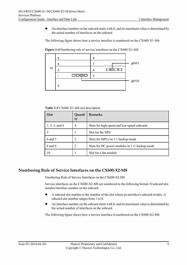
l An interface number on the subcard starts with 0, and its maximum value is determined by
the actual number of interfaces on the subcard.
The following figure shows how a service interface is numbered on the CX600-X1-M4.
Figure 1-4 Numbering rule of service interfaces on the CX600-X1-M4
10
8 9
5
43
2
6 7
1
g0/4/1
g0/1/2
Table 1-3 CX600-X1-M4 slot description
Slot Quantity
Remarks
1, 2, 3, and 4 4 Slots for high-speed and low-speed subcards
5 1 Slot for the NPU
6 and 7 2 Slots for MPUs in 1:1 backup mode
8 and 9 2 Slots for DC power modules in 1+1 backup mode
10 1 Slot for a fan module
Numbering Rule of Service Interfaces on the CX600-X2-M8
Numbering Rule of Service Interfaces on the CX600-X2-M8
Service interfaces on the CX600-X2-M8 are numbered in the following format: 0/subcard slot
number/interface number on the subcard.
l A subcard slot number is the number of the slot where an interface's subcard resides. A
subcard slot number ranges from 1 to 8.
l An interface number on the subcard starts with 0, and its maximum value is determined by
the actual number of interfaces on the subcard.
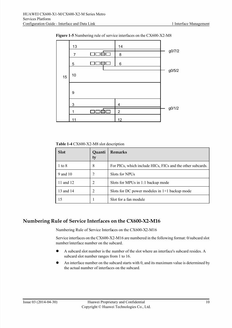
The following figure shows how a service interface is numbered on the CX600-X2-M8.
HUAWEI CX600-X1-M/CX600-X2-M Series Metro
Services Platform
Configuration Guide - Interface and Data Link 1 Interface Management
Issue 03 (2014-04-30) Huawei Proprietary and Confidential
Copyright © Huawei Technologies Co., Ltd.
9
8/18/2019 Cx600 x1 Mcx600 x2 Mv800r005c01configurationguide Interfaceanddatalink03pdf 140820131824 Phpapp02
http://slidepdf.com/reader/full/cx600-x1-mcx600-x2-mv800r005c01configurationguide-interfaceanddatalink03pdf 16/42
Figure 1-5 Numbering rule of service interfaces on the CX600-X2-M8
15
13 14
7 8
65
10
9
3 4
21
11 12
g0/5/2
g0/7/2
g0/1/2
Table 1-4 CX600-X2-M8 slot description
Slot Quantity
Remarks
1 to 8 8 For PICs, which include HICs, FICs and the other subcards.
9 and 10 2 Slots for NPUs
11 and 12 2 Slots for MPUs in 1:1 backup mode
13 and 14 2 Slots for DC power modules in 1+1 backup mode
15 1 Slot for a fan module
Numbering Rule of Service Interfaces on the CX600-X2-M16
Numbering Rule of Service Interfaces on the CX600-X2-M16
Service interfaces on the CX600-X2-M16 are numbered in the following format: 0/subcard slot
number/interface number on the subcard.
l A subcard slot number is the number of the slot where an interface's subcard resides. A
subcard slot number ranges from 1 to 16.
l An interface number on the subcard starts with 0, and its maximum value is determined by
the actual number of interfaces on the subcard.
HUAWEI CX600-X1-M/CX600-X2-M Series Metro
Services Platform
Configuration Guide - Interface and Data Link 1 Interface Management
Issue 03 (2014-04-30) Huawei Proprietary and Confidential
Copyright © Huawei Technologies Co., Ltd.
10

8/18/2019 Cx600 x1 Mcx600 x2 Mv800r005c01configurationguide Interfaceanddatalink03pdf 140820131824 Phpapp02
http://slidepdf.com/reader/full/cx600-x1-mcx600-x2-mv800r005c01configurationguide-interfaceanddatalink03pdf 17/42
Table 1-5 Slot layout of the CX600-X2-M16
Slot Number
Remarks
1 to 16 16 For PICs, which include HICs, FICs and the other subcards.
17 and 18 2 For NPUs.
19 and 20 2 For MPUs, which are in 1:1 backup.
21 and 22 2 For PSUs, which are in 1+1 backup.
23 1 For the fan frame.
1.4 Performing Basic Configurations on an InterfaceThis section describes how to perform basic configurations on an interface. The basic
configurations involve interface types and configurable interface parameters, which enable easy
interface management.
Usage Scenario
To ensure smooth communication between devices on a network, configure both physical and
logical interfaces properly and set the following parameters:
l Interface description
l Maximum transmission unit (MTU)
l Trap threshold for the outbound and inbound bandwidth usage on a specified interface
l Interval at which traffic statistics are collected
l Whether the device sends a trap message to the network management system (NMS) when
the interface status changes
l Whether the control-flap function is enabled
Pre-configuration Tasks
Before performing basic configurations on an interface, verify that the device has been installed
and powered on properly.
HUAWEI CX600-X1-M/CX600-X2-M Series Metro
Services Platform
Configuration Guide - Interface and Data Link 1 Interface Management
Issue 03 (2014-04-30) Huawei Proprietary and Confidential
Copyright © Huawei Technologies Co., Ltd.
11

8/18/2019 Cx600 x1 Mcx600 x2 Mv800r005c01configurationguide Interfaceanddatalink03pdf 140820131824 Phpapp02
http://slidepdf.com/reader/full/cx600-x1-mcx600-x2-mv800r005c01configurationguide-interfaceanddatalink03pdf 18/42
Configuration Procedures
Figure 1-6 Flowchart for performing basic configurations on an interface
Entering the Interface View
Mandatory procedure
Optional procedure
Enabling Interfaces
Setting Interface Parameters
Configuring IPv4 and IPv6 Traffic
Statistics on The Main Interface
1.4.1 Entering the Interface View
The command for entering the view of an interface varies with the physical attribute of the
interface.
Procedure
Step 1 Run:system-view
The system view is displayed.
Step 2 Run:
interface interface-type interface-number
The interface view is displayed.
In this command, interface-type specifies the type of the interface, and interface-number
specifies the number of the interface.
Step 3 (Optional) Run:
commit
The configuration is committed.
If the interface of the specified type and number exists in the preceding step, you do not need to
run the commit command.
----End
1.4.2 (Optional) Setting Interface Parameters
This section describes how to set parameters for an interface based on the actual service
requirements. The parameters include the description, maximum transmission unit (MTU), and
trap threshold for the outbound and inbound bandwidth usage on the interface.
HUAWEI CX600-X1-M/CX600-X2-M Series Metro
Services Platform
Configuration Guide - Interface and Data Link 1 Interface Management
Issue 03 (2014-04-30) Huawei Proprietary and Confidential
Copyright © Huawei Technologies Co., Ltd.
12
8/18/2019 Cx600 x1 Mcx600 x2 Mv800r005c01configurationguide Interfaceanddatalink03pdf 140820131824 Phpapp02
http://slidepdf.com/reader/full/cx600-x1-mcx600-x2-mv800r005c01configurationguide-interfaceanddatalink03pdf 19/42
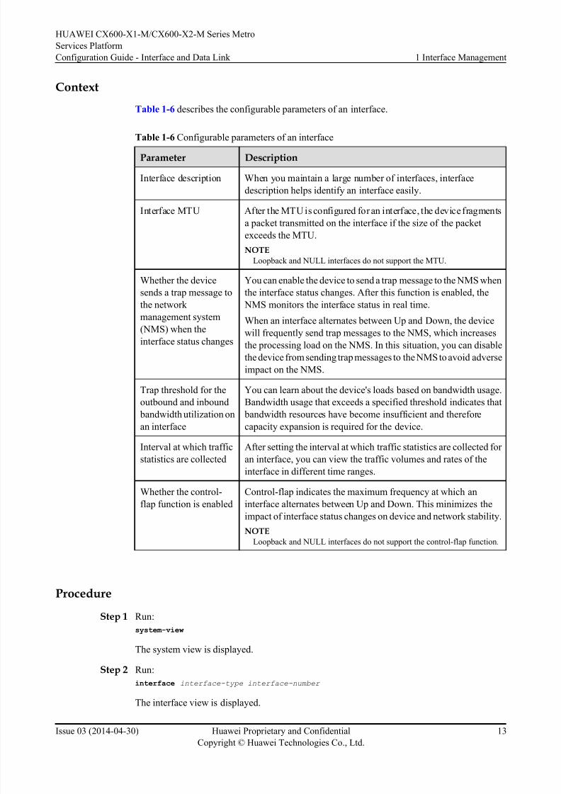
Context
Table 1-6 describes the configurable parameters of an interface.
Table 1-6 Configurable parameters of an interface
Parameter Description
Interface description When you maintain a large number of interfaces, interface
description helps identify an interface easily.
Interface MTU After the MTU is configured for an interface, the device fragments
a packet transmitted on the interface if the size of the packet
exceeds the MTU.
NOTE
Loopback and NULL interfaces do not support the MTU.
Whether the devicesends a trap message to
the network
management system
(NMS) when the
interface status changes
You can enable the device to send a trap message to the NMS whenthe interface status changes. After this function is enabled, the
NMS monitors the interface status in real time.
When an interface alternates between Up and Down, the device
will frequently send trap messages to the NMS, which increases
the processing load on the NMS. In this situation, you can disable
the device from sending trap messages to the NMS to avoid adverse
impact on the NMS.
Trap threshold for the
outbound and inbound
bandwidth utilization onan interface
You can learn about the device's loads based on bandwidth usage.
Bandwidth usage that exceeds a specified threshold indicates that
bandwidth resources have become insufficient and thereforecapacity expansion is required for the device.
Interval at which traffic
statistics are collected
After setting the interval at which traffic statistics are collected for
an interface, you can view the traffic volumes and rates of the
interface in different time ranges.
Whether the control-
flap function is enabled
Control-flap indicates the maximum frequency at which an
interface alternates between Up and Down. This minimizes the
impact of interface status changes on device and network stability.
NOTE
Loopback and NULL interfaces do not support the control-flap function.
Procedure
Step 1 Run:
system-view
The system view is displayed.
Step 2 Run:
interface interface-type interface-number
The interface view is displayed.
HUAWEI CX600-X1-M/CX600-X2-M Series Metro
Services Platform
Configuration Guide - Interface and Data Link 1 Interface Management
Issue 03 (2014-04-30) Huawei Proprietary and Confidential
Copyright © Huawei Technologies Co., Ltd.
13

8/18/2019 Cx600 x1 Mcx600 x2 Mv800r005c01configurationguide Interfaceanddatalink03pdf 140820131824 Phpapp02
http://slidepdf.com/reader/full/cx600-x1-mcx600-x2-mv800r005c01configurationguide-interfaceanddatalink03pdf 20/42
In this command, interface-type specifies the type of the interface, and interface-number
specifies the number of the interface.
Step 3 Perform one or more operations in Table 1-7 to set the desired interface parameters.
Table 1-7 Setting interface parameters
Operation Description
Configure description
for an interface.
Run the description regular-expression command to configure
description for an interface.
By default, no description is configured for an interface
You can view the description of an interface using the display
interface description command.
Set an MTU for an
interface.
Run the mtu mtu or ipv6 mtu mtu command to set an MTU for an
interface.The default MTU is 1500 bytes.
NOTE
l After changing the MTU on a POS interface using the mtu command,
run the shutdown and undo shutdown commands in the interface view
for the change to take effect. Alternatively, you can run the restart
command in the interface view to restart the POS interface for the
change to take effect.
l If IPv4 attributes are configured on an interface, run the mtu command
to set the MTU of the interface.
l If IPv6 attributes are configured on an interface, run the ipv6 mtu
command to set the MTU of the interface.
Configure whether the
device sends a trap
message to the NMS
when the interface
status changes
Run the enable snmp trap updown command to enable the device
to send a trap message to the NMS when the interface status
changes.
By default, the device automatically sends a trap message to the
NMS when the interface status changes.
NOTE
When an interface alternates between Up and Down, the device will
frequently send trap messages to the NMS, which increases the processing
load on the NMS. In this situation, you can run the undo enable snmp trap
updown command to disable the device from sending trap message to the
NMS to avoid adverse impact on the NMS.
Set the trap threshold for
the outbound and
inbound bandwidth
usage on an interface.
Run the trap-threshold { input-rate | output-rate } bandwidth-
in-use [ resume-rate resume-threshold ] command to set the trap
threshold for the outbound and inbound bandwidth usage on an
interface.
The default trap threshold is 100.
If the values of bandwidth-in-use and resume-threshold are too
close to each other, traps will be frequently sent, causing trap
flapping.
HUAWEI CX600-X1-M/CX600-X2-M Series Metro
Services Platform
Configuration Guide - Interface and Data Link 1 Interface Management
Issue 03 (2014-04-30) Huawei Proprietary and Confidential
Copyright © Huawei Technologies Co., Ltd.
14

8/18/2019 Cx600 x1 Mcx600 x2 Mv800r005c01configurationguide Interfaceanddatalink03pdf 140820131824 Phpapp02
http://slidepdf.com/reader/full/cx600-x1-mcx600-x2-mv800r005c01configurationguide-interfaceanddatalink03pdf 21/42
Operation Description
Set the interval at which
traffic statistics are
collected.
Run the set flow-stat interval interval command to set the interval
at which traffic statistics are collected.
The default interval is 300 seconds.NOTE
l To globally set the interval at which traffic statistics are collected, run
the set flow-stat interval interval command in the system view. To set
the interval at which traffic statistics are collected for an interface, run
the interface interface-type interface-number command to specify an
interface and run the set flow-stat interval interval command on the
interface. The global interval applies to all interfaces for which the
interval at which traffic statistics are collected is not set.
l The new interval takes effect after the original interval expires. For a
logical interface, traffic statistics will be updated after the new interval
takes effect and the first interval expires. For a physical interface, traffic
statistics are updated immediately after the new interval takes effect.
Enable the control-flap
function.
Run the control-flap [ suppress reuse ceiling decay-ok decay-
ng ] command to enable the control-flap function on an interface.
By default, the control-flap function is disabled on an interface.
The value of suppress is 1000 times the interface suppression
threshold. It ranges from 1 to 20000. The default value is 2000.
The value of suppress must be greater than the value of reuse and
less than the value of ceiling .
The value of reuse is 1000 times the interface reuse threshold. It
ranges from 1 to 20000. The default value is 750. The value of
reuse must be less than the value of suppress.The value of ceiling is 1000 times the maximum interface
suppression penalty value. It ranges from 1001 to 20000. The
default value is 6000. The value of ceiling must be greater than the
value of suppress.
decay-ok specifies the half life for the penalty value when an
interface is Up. It ranges from 1 to 900, in seconds. The default
value is 54.
decay-ng specifies the half life for the penalty value when an
interface is Down. It ranges from 1 to 900, in seconds. The default
value is 54.
Step 4 Run:
commit
The configuration is committed.
----End
1.4.3 Enabling an Interface
Physical interfaces on a device are initialized and started when the device is powered on.
HUAWEI CX600-X1-M/CX600-X2-M Series Metro
Services Platform
Configuration Guide - Interface and Data Link 1 Interface Management
Issue 03 (2014-04-30) Huawei Proprietary and Confidential
Copyright © Huawei Technologies Co., Ltd.
15
8/18/2019 Cx600 x1 Mcx600 x2 Mv800r005c01configurationguide Interfaceanddatalink03pdf 140820131824 Phpapp02
http://slidepdf.com/reader/full/cx600-x1-mcx600-x2-mv800r005c01configurationguide-interfaceanddatalink03pdf 22/42
Procedure
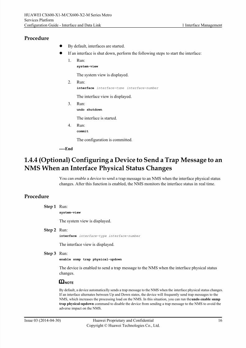
l By default, interfaces are started.
l If an interface is shut down, perform the following steps to start the interface:
1. Run:system-view
The system view is displayed.
2. Run:
interface interface-type interface-number
The interface view is displayed.
3. Run:
undo shutdown
The interface is started.
4. Run:
commit
The configuration is committed.
----End
1.4.4 (Optional) Configuring a Device to Send a Trap Message to anNMS When an Interface Physical Status Changes
You can enable a device to send a trap message to an NMS when the interface physical status
changes. After this function is enabled, the NMS monitors the interface status in real time.
Procedure
Step 1 Run:
system-view
The system view is displayed.
Step 2 Run:
interface interface-type interface-number
The interface view is displayed.
Step 3 Run:
enable snmp trap physical-updown
The device is enabled to send a trap message to the NMS when the interface physical status
changes.
NOTE
By default, a device automatically sends a trap message to the NMS when the interface physical status changes.
If an interface alternates between Up and Down states, the device will frequently send trap messages to the
NMS, which increases the processing load on the NMS. In this situation, you can run the undo enable snmp
trap physical-updown command to disable the device from sending a trap message to the NMS to avoid theadverse impact on the NMS.
HUAWEI CX600-X1-M/CX600-X2-M Series Metro
Services Platform
Configuration Guide - Interface and Data Link 1 Interface Management
Issue 03 (2014-04-30) Huawei Proprietary and Confidential
Copyright © Huawei Technologies Co., Ltd.
16
8/18/2019 Cx600 x1 Mcx600 x2 Mv800r005c01configurationguide Interfaceanddatalink03pdf 140820131824 Phpapp02
http://slidepdf.com/reader/full/cx600-x1-mcx600-x2-mv800r005c01configurationguide-interfaceanddatalink03pdf 23/42
Step 4 Run:
commit
The configuration is committed.
----End
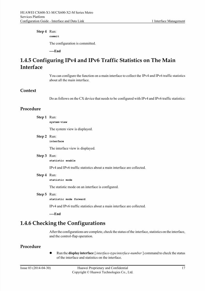
1.4.5 Configuring IPv4 and IPv6 Traffic Statistics on The MainInterface
You can configure the function on a main interface to collect the IPv4 and IPv6 traffic statistics
about all the main interface.
Context
Do as follows on the CX device that needs to be configured with IPv4 and IPv6 traffic statistics:
Procedure
Step 1 Run:
system-view
The system view is displayed.
Step 2 Run:
interface
The interface view is displayed.
Step 3 Run:
statistic enable
IPv4 and IPv6 traffic statistics about a main interface are collected.
Step 4 Run:
statistic mode
The statistic mode on an interface is configured.
Step 5 Run:
statistic mode forward
IPv4 and IPv6 traffic statistics about a main interface are collected.
----End
1.4.6 Checking the Configurations
After the configurations are complete, check the status of the interface, statistics on the interface,
and the control-flap operation.
Procedure
l Run the display interface [ interface-type interface-number ] command to check the status
of the interface and statistics on the interface.
HUAWEI CX600-X1-M/CX600-X2-M Series Metro
Services Platform
Configuration Guide - Interface and Data Link 1 Interface Management
Issue 03 (2014-04-30) Huawei Proprietary and Confidential
Copyright © Huawei Technologies Co., Ltd.
17
8/18/2019 Cx600 x1 Mcx600 x2 Mv800r005c01configurationguide Interfaceanddatalink03pdf 140820131824 Phpapp02
http://slidepdf.com/reader/full/cx600-x1-mcx600-x2-mv800r005c01configurationguide-interfaceanddatalink03pdf 24/42
l Run the display control-flap interface interface-type interface-number command to check
the configuration and running status of the control—flap function on interfaces.
----End
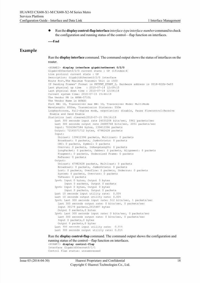
Example
Run the display interface command. The command output shows the status of interfaces on the
router.
<HUAWEI> display interface gigabitethernet 0/2/0
GigabitEthernet0/2/0 current state : UP (ifindex:4)
Line protocol current state : UP
Description: GigabitEthernet0/2/0 Interface
Route Port,The Maximum Transmit Unit is 1500
IP Sending Frames' Format is PKTFMT_ETHNT_2, Hardware address is 0018-82fb-5e03
Last physical up time : 2010-07-14 12:09:15
Last physical down time : 2010-07-14 12:04:18
Current system time: 2010-07-15 15:46:19
The Vendor PN is HFBR-5710L
The Vendor Name is AVAGO
Port BW: 1G, Transceiver max BW: 1G, Transceiver Mode: MultiMode
WaveLength: 850nm, Transmission Distance: 550m
Loopback:none, full-duplex mode, negotiation: disable, Pause Flowcontrol:Receive
Enable and Send Enable
Statistics last cleared:2010-07-15 09:16:19
Last 300 seconds input rate 24035208 bits/sec, 5961 packets/sec
Last 300 seconds output rate 24685768 bits/sec, 2051 packets/sec
Input: 70263847584 bytes, 139412396 packets
Output: 72165571712 bytes, 47982428 packets
Input:
Unicast: 139412396 packets, Multicast: 0 packets
Broadcast: 0 packets, JumboOctets: 0 packets
CRC: 0 packets, Symbol: 0 packets
Overrun: 0 packets, InRangeLength: 0 packets
LongPacket: 0 packets, Jabber: 0 packets, Alignment: 0 packets
Fragment: 0 packets, Undersized Frame: 0 packets
RxPause: 0 packets
Output:
Unicast: 47982428 packets, Multicast: 0 packets
Broadcast: 0 packets, JumboOctets: 0 packets
Lost: 0 packets, Overflow: 0 packets, Underrun: 0 packets
System: 0 packets, Overruns: 0 packets
TxPause: 0 packets
Ipv4: Input 0 bytes, Output 0 bytes
Input 0 packets, Output 0 packets
Ipv6: Input 0 bytes, Output 0 bytes
Input 0 packets, Output 0 packets
Last 10 seconds input utility rate: 0.00%
Last 10 seconds output utility rate: 0.00%Ipv4: Last 300 seconds input rate: 512 bits/sec, 1 packets/sec
Last 300 seconds output rate: 0 bits/sec, 0 packets/sec
Input 30179 packets,2015487 bytes
Output 0 packets,0 bytes
Ipv6: Last 300 seconds input rate: 0 bits/sec, 0 packets/sec
Last 300 seconds output rate: 0 bits/sec, 0 packets/sec
Input 0 packets,0 bytes
Output 0 packets,0 bytes
Last 300 seconds input utility rate: 0.01%
Last 300 seconds output utility rate: 0.01%
Run the display control-flap command. The command output shows the configuration and
running status of the control—flap function on interfaces.<HUAWEI> display control-flap
Interface GigabitEthernet0/1/1Control flap status: unsuppressed
HUAWEI CX600-X1-M/CX600-X2-M Series Metro
Services Platform
Configuration Guide - Interface and Data Link 1 Interface Management
Issue 03 (2014-04-30) Huawei Proprietary and Confidential
Copyright © Huawei Technologies Co., Ltd.
18
8/18/2019 Cx600 x1 Mcx600 x2 Mv800r005c01configurationguide Interfaceanddatalink03pdf 140820131824 Phpapp02
http://slidepdf.com/reader/full/cx600-x1-mcx600-x2-mv800r005c01configurationguide-interfaceanddatalink03pdf 25/42
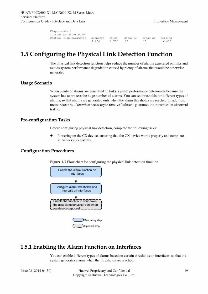
Flap count: 0
Current penalty: 0.000
Control flap parameter: suppress reuse decay-ok decay-ng ceiling
2.000 0.750 15 15 16.000
1.5 Configuring the Physical Link Detection Function
The physical link detection function helps reduce the number of alarms generated on links and
avoids system performance degradation caused by plenty of alarms that would be otherwise
generated.
Usage Scenario
When plenty of alarms are generated on links, system performance deteriorates because the
system has to process the huge number of alarms. You can set thresholds for different types of
alarms, so that alarms are generated only when the alarm thresholds are reached. In addition,
measures can be taken when necessary to remove faults and guarantee the transmission of normal
traffic.
Pre-configuration Tasks
Before configuring physical link detection, complete the following tasks:
l Powering on the CX device, ensuring that the CX device works properly and completes
self-check successfully.
Configuration Procedures
Figure 1-7 Flow chart for configuring the physical link detection function
Enable the alarm function on
interfaces
Enable the function to shut down
the associated physical port whenan alarm is reported
Configure alarm thresholds and
intervals on interfaces
Mandatory step
Optional step
1.5.1 Enabling the Alarm Function on Interfaces
You can enable different types of alarms based on certain thresholds on interfaces, so that the
system generates alarms when the thresholds are reached.
HUAWEI CX600-X1-M/CX600-X2-M Series Metro
Services Platform
Configuration Guide - Interface and Data Link 1 Interface Management
Issue 03 (2014-04-30) Huawei Proprietary and Confidential
Copyright © Huawei Technologies Co., Ltd.
19

8/18/2019 Cx600 x1 Mcx600 x2 Mv800r005c01configurationguide Interfaceanddatalink03pdf 140820131824 Phpapp02
http://slidepdf.com/reader/full/cx600-x1-mcx600-x2-mv800r005c01configurationguide-interfaceanddatalink03pdf 26/42
Context
If the alarm function is enabled on an interface, the system generates an alarm when the number
of errors or bandwidth utilization exceeds or falls below the threshold set on the interface. If the
alarm function is disabled, the system does not generate any alarm, no matter whether the number
of errors or bandwidth utilization exceeds or falls below the set threshold. The configuration
takes effect on all physical ports supporting the alarm function.
Do as follows on the interfaces that are connected to transmission devices:
Procedure
Step 1 Run:
system-view
The system view is displayed.
Step 2 Run:
snmp-agent trap enable port { crc-error-rising | sdh-error-rising | optical-module-
abnormal }
The alarm function is enabled on interfaces.
Different types of alarms can be set on an interface as necessary.
l crc-error-rising: Enables the alarm function for CRC errors on an interface.
l sdh-error-rising: Enables the alarm function for SDH errors on an interface.
l optical-module-abnormal: Enables the alarm function for abnormal optical power of the
optical module on an interface.
Step 3 Run:
commit
The configuration is committed.
----End
1.5.2 Configuring Alarm Thresholds and Intervals on Interfaces
You can configure the types of interface alarms for the system to process, the thresholds for
generating and reporting alarms to the network management system (NMS), and alarm intervals,
so that the system has to process only a limited number of alarms. This avoids system performance degradation caused by plenty of alarms that would be otherwise generated on links.
Context
Perform the following steps on the interfaces that are connected to transport devices:
Procedure
Step 1 Run:
system-view
The system view is displayed.
HUAWEI CX600-X1-M/CX600-X2-M Series Metro
Services Platform
Configuration Guide - Interface and Data Link 1 Interface Management
Issue 03 (2014-04-30) Huawei Proprietary and Confidential
Copyright © Huawei Technologies Co., Ltd.
20

8/18/2019 Cx600 x1 Mcx600 x2 Mv800r005c01configurationguide Interfaceanddatalink03pdf 140820131824 Phpapp02
http://slidepdf.com/reader/full/cx600-x1-mcx600-x2-mv800r005c01configurationguide-interfaceanddatalink03pdf 27/42
Step 2 Run:
interface interface-type interface-number
The interface view is displayed.
Step 3 Configure thresholds for different types of interface alarms and the alarm intervals as necessary.l Configure the alarm threshold for inbound and outbound bandwidth usage:
– Run:
trap-threshold { input-rate | output-rate } bandwidth-in-use [ resume-rate
resume-threshold ]
The inbound and outbound bandwidth usage threshold for generating an alarms is set.
The default inbound and outbound bandwidth usage threshold for generating an alarm is
100%.
To avoid frequent alarm display, ensure that the difference between the value of
bandwidth-in-use and the value of resume-threshold is large.
–Run:
set flow-stat interval interval
The traffic statistics interval of the interface is set.
The new traffic statistics interval takes effect after the original traffic statistics interval
expires. If the interface is a logic interface, traffic statistics about the interface are updated
upon the arrival of the second cycle after the new traffic statistics interval takes effect. If
the interface is a physical interface, traffic statistics about the interface are updated
immediately after the new traffic statistics interval takes effect.
The traffic statistics interval set for an interface is effective for only the interface to show
traffic and rate information about the interface.
NOTE
You can configure a global traffic statistics interval, which takes effect on all the interfaces,
including the interfaces for which no traffic statistics interval has been set. To configure a global
traffic statistics interval for multiple interfaces, run the set flow-stat interval interval command
in the system view. The traffic statistics interval of an interface, in seconds, takes preference over
a global traffic statistics interval.
l Configure CRC alarm thresholds and an alarm interval (for Ethernet interfaces and and POS
interfaces using either of the following two methods):
– Run:
trap-threshold crc-error threshold interval-second interval
An alarm threshold is set based on a specified interval. A device will generate an alarmif the number of packets with CRC errors received within the interval exceeds the
configured alarm threshold.
By default, the threshold for generating a CRC alarm is 3 and the alarm interval is 10
seconds.
– Run:
trap-threshold crc-error high-threshold high-threshold low-threshold low-
threshold interval-second interval
The high threshold and low threshold for generating a CRC alarm, and the alarm interval
are set.
By default, the high threshold for generating a CRC alarm is 1000, the low threshold is
100, and the alarm interval is 10 seconds.
HUAWEI CX600-X1-M/CX600-X2-M Series Metro
Services Platform
Configuration Guide - Interface and Data Link 1 Interface Management
Issue 03 (2014-04-30) Huawei Proprietary and Confidential
Copyright © Huawei Technologies Co., Ltd.
21
8/18/2019 Cx600 x1 Mcx600 x2 Mv800r005c01configurationguide Interfaceanddatalink03pdf 140820131824 Phpapp02
http://slidepdf.com/reader/full/cx600-x1-mcx600-x2-mv800r005c01configurationguide-interfaceanddatalink03pdf 28/42
NOTE
In the system view, you can run the trap-threshold slot slot-id card card-id crc-error high-
threshold high-threshold low-threshold low-threshold interval-second interval command for the
configurations to take effect for all ports on the specified subcard.
l Configure SDH alarm thresholds and an alarm interval (for 10GE WAN interfaces and andPOS interfaces using either of the following two methods):
– Run:
trap-threshold sdh-error threshold interval-second interval
An alarm threshold is set based on a specified interval. A device will generate an alarm
if the number of packets with SDH errors received within the specified interval exceeds
the configured alarm threshold.
By default, the threshold for generating an SDH alarm is 3 and the alarm interval is 10
seconds.
– Run:
trap-threshold sdh-error high-threshold high-threshold low-threshold low-
threshold interval-second interval
The high threshold and low threshold for generating an SDH alarm, and the alarm interval
are set.
By default, the high threshold for generating an SDH alarm is 1000, the low threshold is
100, and the interval is 10 seconds.
NOTE
In the system view, you can run the trap-threshold slot slot-id card card-id sdh-error high-
threshold high-threshold low-threshold low-threshold interval-second interval command for the
configurations to take effect for all ports on the specified subcard.
l Configure symbol alarm thresholds and an alarm interval (for Ethernet interfaces only).
Run:
trap-threshold symbol-error high-threshold high-threshold low-threshold low-
threshold interval-second interval
The high threshold and low threshold for generating a symbol alarm, and the alarm interval
are set.
By default, the high threshold for generating a symbol alarm is 1000, the low threshold is
100, and the alarm interval is 10 seconds.
NOTE
In the system view, you can run the trap-threshold slot slot-id card card-id symbol-error high-
threshold high-threshold low-threshold low-threshold interval-second interval command for the
configurations to take effect for all ports on the specified subcard.
l Configure input/output alarm thresholds and an alarm interval (for Ethernet interfaces and
POS interfaces).
Run:
trap-threshold { input-error | output-error } high-threshold high-threshold low-
threshold low-threshold interval-second interval
The high and low thresholds for generating an interface input or output alarm are set.
By default, the high threshold for generating an input or output alarm is 1000, the low
threshold is 100, and the alarm interval is 10 seconds.
HUAWEI CX600-X1-M/CX600-X2-M Series Metro
Services Platform
Configuration Guide - Interface and Data Link 1 Interface Management
Issue 03 (2014-04-30) Huawei Proprietary and Confidential
Copyright © Huawei Technologies Co., Ltd.
22

8/18/2019 Cx600 x1 Mcx600 x2 Mv800r005c01configurationguide Interfaceanddatalink03pdf 140820131824 Phpapp02
http://slidepdf.com/reader/full/cx600-x1-mcx600-x2-mv800r005c01configurationguide-interfaceanddatalink03pdf 29/42
NOTE
In the system view, you can run the trap-threshold slot slot-id card card-id { input-error | output-
error } high-threshold high-threshold low-threshold low-threshold interval-second interval
command for the configurations to take effect for all ports on the specified subcard.
l Configure an alarm threshold and an alarm recovery threshold for the CRC error packet ratio:
Run:
trap-threshold crc-error packet-error-ratio alarm-threshold coefficient-value
power-value [ resume-threshold coefficient-value power-value ] [ trigger-lsp |
trigger-section ]
An alarm threshold and an alarm recovery threshold for the CRC error packet ratio are set.
l Configure the parameters of the algorithm for calculating the CRC packet error ratio:
Run:
crc-error packet-error-ratio algorithm-parameter sample-window-factor child-
window-max-number child-window-alarm-number child-window-resume-number
The parameters of the algorithm for calculating the CRC packet error ratio are set.
Step 4 Run:
commit
The configuration is committed.
----End
1.5.3 (Optional) Enabling the Function to Shut Down the AssociatedPhysical Port When an Alarm Is Reported
If this function is enabled, the associated physical port will be down when an alarm is reported.
Context
Do as follows on the interfaces that are connected to transmission devices:
Procedure
Step 1 Run:
system-view
The system view is displayed.
Step 2 Run:
interface interface-type interface-number
The interface view is displayed.
Step 3 Run:
port-alarm down { crc-error | sdh-error | symbol-error | input-error | output-
error }
The function is enabled to shut down the associated physical port when an alarm is reported.
HUAWEI CX600-X1-M/CX600-X2-M Series Metro
Services Platform
Configuration Guide - Interface and Data Link 1 Interface Management
Issue 03 (2014-04-30) Huawei Proprietary and Confidential
Copyright © Huawei Technologies Co., Ltd.
23

8/18/2019 Cx600 x1 Mcx600 x2 Mv800r005c01configurationguide Interfaceanddatalink03pdf 140820131824 Phpapp02
http://slidepdf.com/reader/full/cx600-x1-mcx600-x2-mv800r005c01configurationguide-interfaceanddatalink03pdf 30/42
NOTE
l On the CX device, you can also run the port-alarm down slot slot-id card card-id { crc-error | sdh-
error | symbol-error | input-error | output-error } command in the system view. The configurations
take effect for all interfaces on the specified subcard.
l After the function is enabled, you can run the port-alarm clear { crc-error | sdh-error | symbol-error | input-error | output-error } command to manually clear alarms generated on physical ports.
Step 4 Run:
commit
The configuration is committed.
----End
1.5.4 Checking the Configuration
You can check the interface configuration and state information after configuring the physical
link detection function.
Context
You can check the interface configuration and state information after configuring the physical
link detection function.
Procedure
l Run the display trap-info command in the interface view, or run the display trap-info
{ interface-type interface-number | interface-name | slot slot-id card card-id } command
in the system view to check configuration and state information about the specifiedinterface, including whether the alarm function is enabled on the interface, alarm threshold,
alarm interval, alarm blocking, current alarm state, and the number of current alarms.
l Run the display port-error-info interface { interface-type interface-number | interface-
nameommand in the interface view to check the trap information about error codes/error
packets of an interface.
----End
Example
Run the display trap-info command on the GE interface 0/1/0.
<HUAWEI> system-view
[~HUAWEI] interface gigabitethernet 0/1/0
[~HUAWEI-GigabitEthernet0/1/0] display trap-info
==========================================================================
Gigabiethernet0/1/0 trap information
================|=========================================================
trapEnable high-threshold low-threshold interval downFlag alarmFlag Statistics
----------------|---------------------------------------------------------
crc-error enable 3 3 10 disable alarm 100
input-error enable 1000 100 10 disable none 0
output-error enable 1000 100 10 disable none 0
symbol-error enable 1000 100 10 disable none 0
local-fault enable - - - - none -
remote-fault enable - - - - none -
hi-ber enable - - - - none -bip8-sd enable 6 7 - disable none -
HUAWEI CX600-X1-M/CX600-X2-M Series Metro
Services Platform
Configuration Guide - Interface and Data Link 1 Interface Management
Issue 03 (2014-04-30) Huawei Proprietary and Confidential
Copyright © Huawei Technologies Co., Ltd.
24

8/18/2019 Cx600 x1 Mcx600 x2 Mv800r005c01configurationguide Interfaceanddatalink03pdf 140820131824 Phpapp02
http://slidepdf.com/reader/full/cx600-x1-mcx600-x2-mv800r005c01configurationguide-interfaceanddatalink03pdf 31/42
BIP8 statistics: EB 1000, ES 50, SES 20, UAS 15, BBE 800.
Run the display port-error-info command on the GE interface 0/1/0:<HUAWEI> system-view
[~HUAWEI] interface gigabitethernet 0/1/0
[~HUAWEI-GigabitEthernet0/1/0] display port-error-info interface GigabitEthernet0/1/0
GigabitEthernet0/1/0 port-error information
GigabitEthernet0/1/0 port-error information
================================================================================
b1tca | b2tca | b3tca
--------------------------------------------------------------------------------
trap enable : Yes | trap enable : Yes | trap enable : Yes
trigger down: No | trigger down: No | trigger down: No
alarm status: No | alarm status: No | alarm status: No
threshold : 6 (10e-n) | threshold : 6 (10e-n) | threshold : 6 (10e-n)
================================================================================
sdh-b1-error | sdh-b2-error | sdh-error
--------------------------------------------------------------------------------
trap enable : Yes | trap enable : Yes | trap enable : Yes
trigger down: No | trigger down: No | trigger down: No
alarm status: No | alarm status: No | alarm status: No
threshold : 3 | threshold : 3 | threshold : 3
interval : 10 sec. | interval : 10 sec. | interval : 10 sec.
stat(h) : 0 | stat(h) : 0 | stat(h) : 0
stat(l) : 0 | stat(l) : 0 | stat(l) : 0
================================================================================
sdbere | sfbere
--------------------------------------------------------------------------------
trap enable : Yes | trap enable : Yes
trigger down : No | trigger down : No
alarm status : No | alarm status : No
threshold : 6(10e-n) | threshold : 3(10e-n)
================================================================================
input-error | output-error
--------------------------------------------------------------------------------
trap enable : Yes | trap enable : Yes
HUAWEI CX600-X1-M/CX600-X2-M Series Metro
Services Platform
Configuration Guide - Interface and Data Link 1 Interface Management
Issue 03 (2014-04-30) Huawei Proprietary and Confidential
Copyright © Huawei Technologies Co., Ltd.
25
8/18/2019 Cx600 x1 Mcx600 x2 Mv800r005c01configurationguide Interfaceanddatalink03pdf 140820131824 Phpapp02
http://slidepdf.com/reader/full/cx600-x1-mcx600-x2-mv800r005c01configurationguide-interfaceanddatalink03pdf 32/42
trigger down : No | trigger down : No
alarm status : No | alarm status : No
threshold high : 1000 | threshold high : 1000
threshold low : 100 | threshold low : 100
interval : 10 sec. | interval : 10 sec.
stat(h) : 0 | stat(h) : 0
stat(l) : 0 | stat(l) : 0
================================================================================
crc-error | symbol-error
--------------------------------------------------------------------------------
trap enable : Yes | trap enable : Yes
trigger down : No | trigger down : No
alarm status : No | alarm status : No
threshold high : 3 | threshold high : 1000
threshold low : 3 | threshold low : 100
percent : 0 | N/A : N/A
interval : 10 sec. | interval : 10 sec.
stat(h) : 0 | stat(h) : 0
stat(l) : 0 | stat(l) : 0
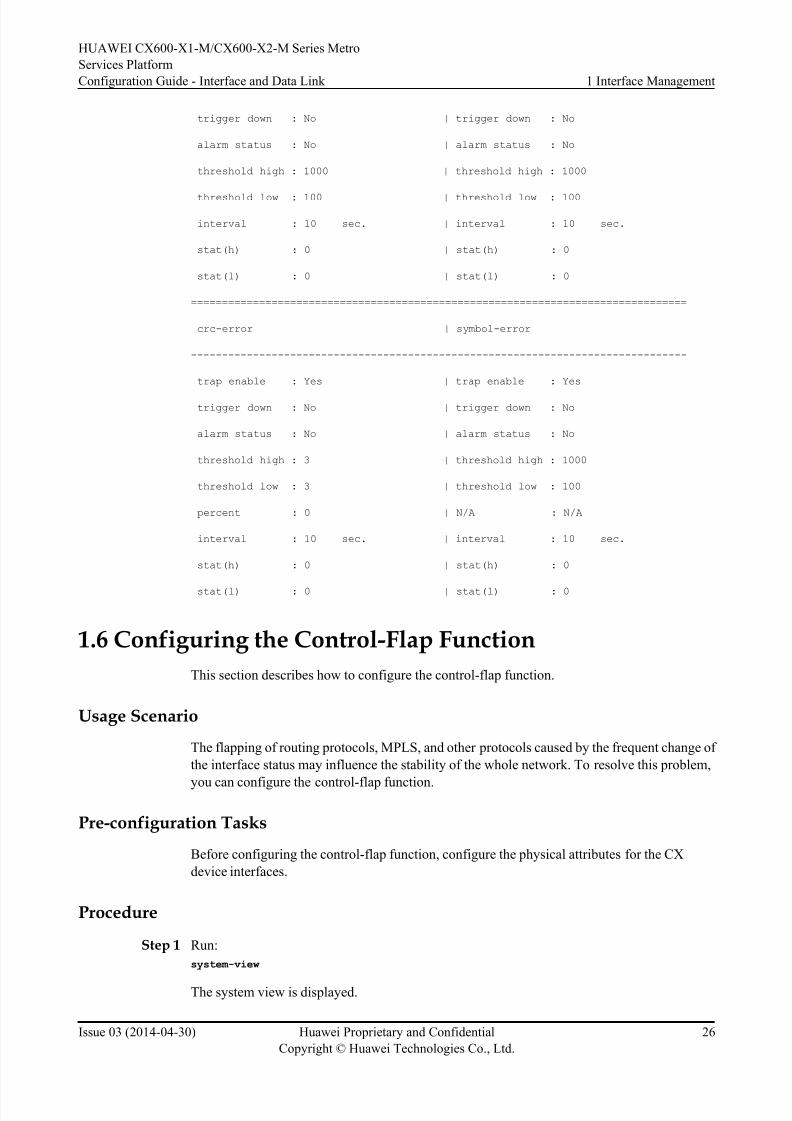
1.6 Configuring the Control-Flap Function
This section describes how to configure the control-flap function.
Usage Scenario
The flapping of routing protocols, MPLS, and other protocols caused by the frequent change of
the interface status may influence the stability of the whole network. To resolve this problem,
you can configure the control-flap function.
Pre-configuration Tasks
Before configuring the control-flap function, configure the physical attributes for the CX
device interfaces.
Procedure
Step 1 Run:
system-view
The system view is displayed.
HUAWEI CX600-X1-M/CX600-X2-M Series Metro
Services Platform
Configuration Guide - Interface and Data Link 1 Interface Management
Issue 03 (2014-04-30) Huawei Proprietary and Confidential
Copyright © Huawei Technologies Co., Ltd.
26

8/18/2019 Cx600 x1 Mcx600 x2 Mv800r005c01configurationguide Interfaceanddatalink03pdf 140820131824 Phpapp02
http://slidepdf.com/reader/full/cx600-x1-mcx600-x2-mv800r005c01configurationguide-interfaceanddatalink03pdf 33/42
Step 2 Run:
interface interface-type interface-number
The interface view is displayed.
NOTE
The null interface and loopback interface do not support the control-flap function.
Step 3 Run:
control-flap [ suppress reuse ceiling decay-ok decay-ng ]
The control—flap function is enabled on the interface.
The value of suppress is 1000 times the suppress threshold of the interface. It ranges from 1 to
20000. The default value is 2000. The value of suppress must be greater than the value of
reuse and smaller than the value of ceiling .
The value of reuse is 1000 times the reuse threshold of the interface. It ranges from 1 to 20000.
The default value is 750. The value of reuse must be smaller than the value of suppress.
The value of ceiling is 1000 times the suppress penalty value of the interface. It ranges from
1001 to 20000. The default value is 6000. The value of ceiling must be greater than the value of
suppress.
The value of decay-ok is the time taken to decay the penalty value to half when the interface is
Up. It ranges from 1 to 900 seconds. The default value is 54 seconds.
The value of decay-ng is the time taken to decay the penalty value to half when the interface is
Down. It ranges from 1 to 900 seconds. The default value is 54 seconds.
Step 4 Run:
commit
The configuration is committed.
----End
Checking the Configuration
Run the display control-flap interface interface-type interface-number command to check the
previous configuration.
<HUAWEI> display control-flap
Interface GigabitEthernet1/0/1
Control flap status: unsuppressed
Flap count: 0
Current penalty: 0.000
Control flap parameter: suppress reuse decay-ok decay-ng ceiling
2.000 0.750 15 15 16.000
1.7 Enabling the Signal Sending Delay Function
This section describes how to configure the signal sending delay function.
HUAWEI CX600-X1-M/CX600-X2-M Series Metro
Services Platform
Configuration Guide - Interface and Data Link 1 Interface Management
Issue 03 (2014-04-30) Huawei Proprietary and Confidential
Copyright © Huawei Technologies Co., Ltd.
27
8/18/2019 Cx600 x1 Mcx600 x2 Mv800r005c01configurationguide Interfaceanddatalink03pdf 140820131824 Phpapp02
http://slidepdf.com/reader/full/cx600-x1-mcx600-x2-mv800r005c01configurationguide-interfaceanddatalink03pdf 34/42
Usage Scenario
After a device is restarted or a board is replaced, if an interface sends signals immediately after
initialization before the link completes a switchover or configuration restoration, data loss may
occur. To prevent data loss, configure the signal sending delay function.
NOTE
l Only physical interfaces can be configured with signal sending delays. Logical interfaces do not support
this function.
l Configuring a signal sending delay does not affect an interface that has sent signals to the peer, and
the configuration takes effect after the interface is initialized.
Procedure
Step 1 Run:
system-view
The system view is displayed.
Step 2 Perform either of the following configurations as required.
1. Run:
interface interface-type interface-number
The GE, POS, 10GE WAN or 10G LANinterface view is displayed.
2. Run:
controller e1 controller-number
The CE1 interface view is displayed.
Step 3 Run:
port-tx-enabling-delay port-tx-delay-time
The signal sending delay function is enabled, and the signal sending delay is configured.
By default, the signal sending delay on an interface is 0 milliseconds, indicating that the interface
sends a signal immediately after being initialized.
----End
1.8 Configuring an Interface Monitoring Group
In a dual-device backup scenario, you can configure an interface monitoring group to allow the
user-side interface status to change with the network-side interface status so that traffic can be
switched between the master and backup links.
Usage Scenario
In a dual-device backup scenario, when a network-side interface goes Down, user-side devices
cannot detect the Down event and therefore do not switch traffic to the backup link. As a result,
traffic overloads or interruptions occur. To prevent these problems, you can configure an
interface monitoring group to monitor the network-side interface status and instruct the user-
side interface to change its status accordingly. An interface monitoring group allows traffic to
be switched between the master and backup links and prevents traffic overloads or interruptions.
HUAWEI CX600-X1-M/CX600-X2-M Series Metro
Services Platform
Configuration Guide - Interface and Data Link 1 Interface Management
Issue 03 (2014-04-30) Huawei Proprietary and Confidential
Copyright © Huawei Technologies Co., Ltd.
28
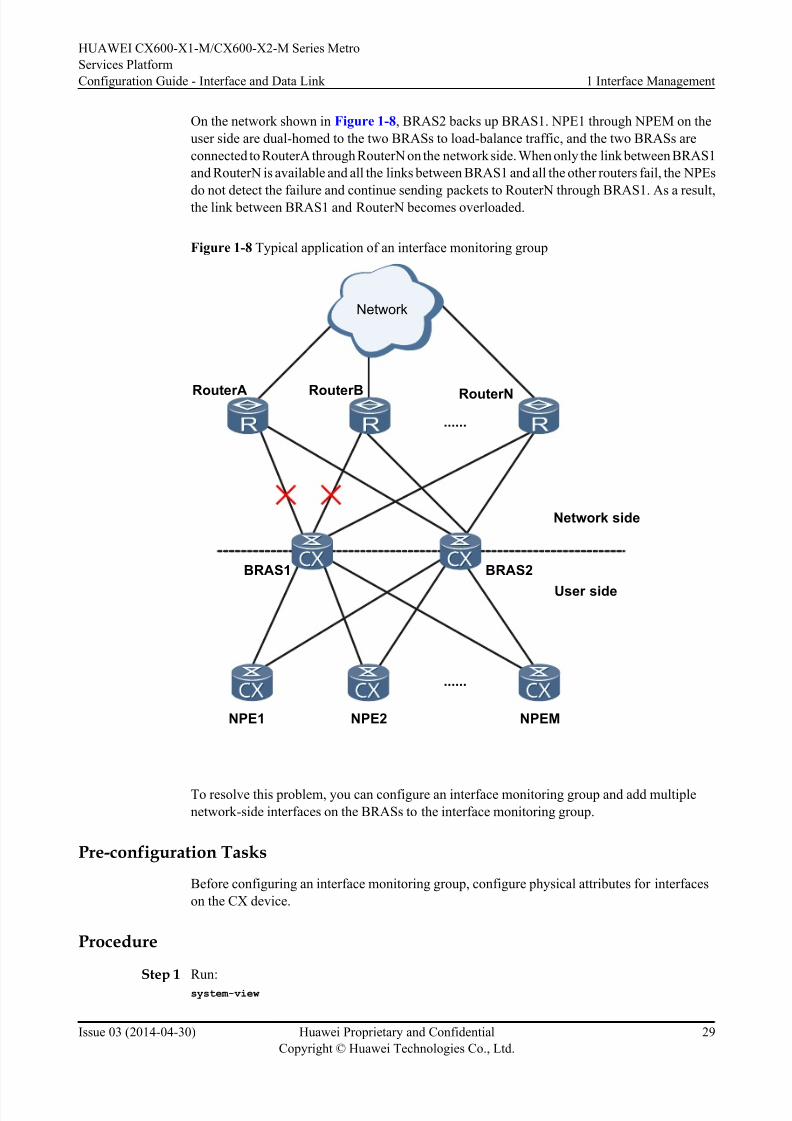
8/18/2019 Cx600 x1 Mcx600 x2 Mv800r005c01configurationguide Interfaceanddatalink03pdf 140820131824 Phpapp02
http://slidepdf.com/reader/full/cx600-x1-mcx600-x2-mv800r005c01configurationguide-interfaceanddatalink03pdf 35/42
On the network shown in Figure 1-8, BRAS2 backs up BRAS1. NPE1 through NPEM on the
user side are dual-homed to the two BRASs to load-balance traffic, and the two BRASs are
connected to RouterA through RouterN on the network side. When only the link between BRAS1
and RouterN is available and all the links between BRAS1 and all the other routers fail, the NPEs
do not detect the failure and continue sending packets to RouterN through BRAS1. As a result,the link between BRAS1 and RouterN becomes overloaded.
Figure 1-8 Typical application of an interface monitoring group
......
......
Network side
User side
RouterA RouterB RouterN
NPE1 NPE2 NPEM
BRAS1 BRAS2
Network
To resolve this problem, you can configure an interface monitoring group and add multiple
network-side interfaces on the BRASs to the interface monitoring group.
Pre-configuration Tasks
Before configuring an interface monitoring group, configure physical attributes for interfaces
on the CX device.
Procedure
Step 1Run:
system-view
HUAWEI CX600-X1-M/CX600-X2-M Series Metro
Services Platform
Configuration Guide - Interface and Data Link 1 Interface Management
Issue 03 (2014-04-30) Huawei Proprietary and Confidential
Copyright © Huawei Technologies Co., Ltd.
29
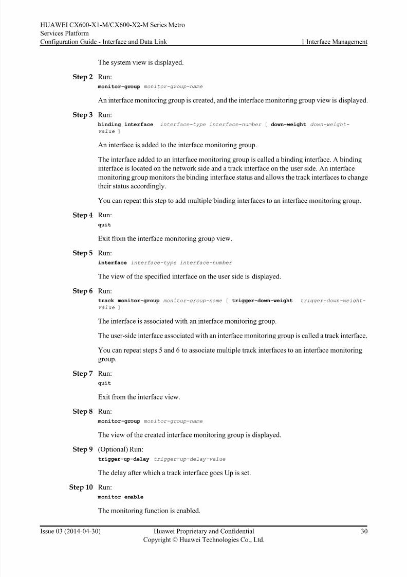
8/18/2019 Cx600 x1 Mcx600 x2 Mv800r005c01configurationguide Interfaceanddatalink03pdf 140820131824 Phpapp02
http://slidepdf.com/reader/full/cx600-x1-mcx600-x2-mv800r005c01configurationguide-interfaceanddatalink03pdf 36/42
The system view is displayed.
Step 2 Run:
monitor-group monitor-group-name
An interface monitoring group is created, and the interface monitoring group view is displayed.
Step 3 Run:
binding interface interface-type interface-number [ down-weight down-weight-
value ]
An interface is added to the interface monitoring group.
The interface added to an interface monitoring group is called a binding interface. A binding
interface is located on the network side and a track interface on the user side. An interface
monitoring group monitors the binding interface status and allows the track interfaces to change
their status accordingly.
You can repeat this step to add multiple binding interfaces to an interface monitoring group.
Step 4 Run:
quit
Exit from the interface monitoring group view.
Step 5 Run:
interface interface-type interface-number
The view of the specified interface on the user side is displayed.
Step 6 Run:
track monitor-group monitor-group-name
[trigger-down-weight trigger-down-weight-
value ]
The interface is associated with an interface monitoring group.
The user-side interface associated with an interface monitoring group is called a track interface.
You can repeat steps 5 and 6 to associate multiple track interfaces to an interface monitoring
group.
Step 7 Run:
quit
Exit from the interface view.
Step 8 Run:
monitor-group monitor-group-name
The view of the created interface monitoring group is displayed.
Step 9 (Optional) Run:
trigger-up-delay trigger-up-delay-value
The delay after which a track interface goes Up is set.
Step 10 Run:
monitor enable
The monitoring function is enabled.
HUAWEI CX600-X1-M/CX600-X2-M Series Metro
Services Platform
Configuration Guide - Interface and Data Link 1 Interface Management
Issue 03 (2014-04-30) Huawei Proprietary and Confidential
Copyright © Huawei Technologies Co., Ltd.
30

8/18/2019 Cx600 x1 Mcx600 x2 Mv800r005c01configurationguide Interfaceanddatalink03pdf 140820131824 Phpapp02
http://slidepdf.com/reader/full/cx600-x1-mcx600-x2-mv800r005c01configurationguide-interfaceanddatalink03pdf 37/42
Step 11 Run:
commit
The configuration is committed.
----End
Checking the Configurations
After configuring an interface monitoring group, check the configurations.
l Run the display monitor-group [ monitor-group-name ] command to view information
about an interface monitoring group.
For example, run the display monitor-group group1 command to view information about an
interface monitoring group named group1.
<HUAWEI> display monitor-group group1monitor-group group1
Index : 1
Down weight : 10
Weight sum : 10
Max track weight : 10
Trigger-up delay : 100 (s)
Status : Inactive
-------------------------------------------------------
monitor-group binding interface number : 1
-------------------------------------------------------
Interface name : Pos0/5/0
Interface index : 17
Down-weight : 10
Phystatus : DOWN
Bfdstatus : - LastPhyuptime : -
LastPhydowntime : 2013-02-27 01:20:49+01:00 DST
LastBFDuptime : -
LastBFDdowntime : -
ValidFlag : valid
-------------------------------------------------------
monitor-group track interface number : 1
-------------------------------------------------------
Interface name : Ethernet0/1/5
Interface index : 12
Trigger-down-weight : 0 (default)
TriggerStatus : TRIGGER UP
LastTriggerUpTime : 2013-02-27 02:51:40+01:00 DST
LastTriggerDownTime : 2013-02-27 01:20:49+01:00 DST
ValidFlag : valid
1.9 Configuring Logical Interfaces
This section describes how to configure logical interfaces. Logical interfaces are manually
configured interfaces, which are used to exchange data. Logical interfaces do not exist
physically.
Usage Scenario
Table 1-8 describes the usage scenario of loopback and NULL interfaces.
HUAWEI CX600-X1-M/CX600-X2-M Series Metro
Services Platform
Configuration Guide - Interface and Data Link 1 Interface Management
Issue 03 (2014-04-30) Huawei Proprietary and Confidential
Copyright © Huawei Technologies Co., Ltd.
31

8/18/2019 Cx600 x1 Mcx600 x2 Mv800r005c01configurationguide Interfaceanddatalink03pdf 140820131824 Phpapp02
http://slidepdf.com/reader/full/cx600-x1-mcx600-x2-mv800r005c01configurationguide-interfaceanddatalink03pdf 38/42
Table 1-8 Usage scenarios of loopback and NULL interfaces.
Interface Type Usage Scenario Description
Loopback interface Once a loopback interface is
created, its status and datalink protocol status are
always Up, regardless of
whether an IP address is
configured for the loopback
interface. If the status of an
interface must always remain
Up, configure a loopback
address for the interface.
The advantages of a loopback
interface help improve
configuration reliability.Loopback interfaces can be
used as follows:
l The IP address of a
loopback interface can be
the source IP address of a
packet to improve
network reliability.
l The IP address of a
loopback interface can be
used to control an access
interface and filter logs tosimplify displayed
information.
l No data link layer
protocols can beencapsulated on a
loopback interface. That
is, no negotiation is
performed at the data link
layer. Therefore, the data
link protocol status
always remains Up.
l Packets with a source IP
address belonging to the
loopback interface on a
host must not betransmitted outside of the
host and must be dropped
if received on a network
interface.
NULL interface The CX600 supports only
one NULL interface, which is
called NULL0 interface. The
NULL0 interface is always in
the Up state but never
forwards any data packets.
That is, any data packets sent
to the NULL0 interface are
discarded. This characteristic
enables the NULL0 interface
to be used for routing loop
prevention and traffic
filtering.
No IP address can be
configured on the NULL0
interface, or no data link layer
protocol can be encapsulated
on the NULL0 interface.
NOTE
Loopback and NULL interfaces have special functions and can be configured for a specific service as
required. For details about loopback and NULL interface configurations, see the configuration guide for aspecific service.
HUAWEI CX600-X1-M/CX600-X2-M Series Metro
Services Platform
Configuration Guide - Interface and Data Link 1 Interface Management
Issue 03 (2014-04-30) Huawei Proprietary and Confidential
Copyright © Huawei Technologies Co., Ltd.
32
8/18/2019 Cx600 x1 Mcx600 x2 Mv800r005c01configurationguide Interfaceanddatalink03pdf 140820131824 Phpapp02
http://slidepdf.com/reader/full/cx600-x1-mcx600-x2-mv800r005c01configurationguide-interfaceanddatalink03pdf 39/42
Pre-configuration Tasks
Before configuring logical interfaces, connect interfaces and set their physical parameters to
ensure that these interfaces are physically Up.
Configuration Procedures
Perform one or more of the following configurations (excluding checking the configuration) as
required.
1.9.1 Creating a Loopback Interface and Configuring Its IP Address
In most cases, you need to assign IP addresses to loopback interfaces, and then use the loopback
interfaces that are always Up to communicate with other devices.
Procedure
Step 1 Run:
system-view
The system view is displayed.
Step 2 Run:
interface loopback loopback-number
A loopback interface is created.
You can create or delete loopback interfaces dynamically. Once a loopback interface is created,
it remains Up all the time until it is deleted.
Step 3 Run:
ip address ip-address [ mask | mask-length ]
The IP address of the loopback interface is configured.
Step 4 Run:
commit
The configuration is committed.
----End
1.9.2 Entering the NULL Interface ViewThe system automatically creates a NULL0 interface. The NULL interface is used for preventing
routing loops and filtering traffic.
Procedure
Step 1 Run:
system-view
The system view is displayed.
Step 2 Run:interface null 0
HUAWEI CX600-X1-M/CX600-X2-M Series Metro
Services Platform
Configuration Guide - Interface and Data Link 1 Interface Management
Issue 03 (2014-04-30) Huawei Proprietary and Confidential
Copyright © Huawei Technologies Co., Ltd.
33

8/18/2019 Cx600 x1 Mcx600 x2 Mv800r005c01configurationguide Interfaceanddatalink03pdf 140820131824 Phpapp02
http://slidepdf.com/reader/full/cx600-x1-mcx600-x2-mv800r005c01configurationguide-interfaceanddatalink03pdf 40/42
The NULL interface view is displayed.
The NULL interface is always in the Up state but does not forward any data packets. In addition,
IP addresses cannot be configured on the NULL interface, and data link layer protocol cannot
be encapsulated on the NULL interface.
----End
Follow-up Procedure
The NULL interface is used to prevent routing loops and filtering traffic. If the ip route-static
192.168.0.0 255.255.0.0 NULL 0 command is run, the device will discard all packets destined
for the network segment 192.168.0.0.
1.9.3 Checking the Configuration
After the configuration on the interface is completed, check the configurations.
Prerequisites
Configuration of the Loopback interface or NULL interface is completed.
Procedure
l Run the display interface loopback [ loopback-number ] command to check the status of
the Loopback interface.
l Run the display interface null [ 0 ] command to check the status of the NULL interface.
----End
Example
Run the display interface loopback command. The command output shows that the status of
the link protocol on the Loopback interface is UP.
<HUAWEI> display interface loopback 1
LoopBack0 current state : UP (ifindex: 39)
Line protocol current state : UP (spoofing)
Description:
Route Port,The Maximum Transmit Unit is 1500
Internet protocol processing : disabled
Current system time: 2010-07-15 16:58:21
Physical is Loopback
Last 300 seconds input rate 0 bits/sec, 0 packets/sec
Last 300 seconds output rate 0 bits/sec, 0 packets/sec
Realtime 0 seconds input rate 0 bits/sec, 0 packets/sec
Realtime 0 seconds output rate 0 bits/sec, 0 packets/sec
Input: 0 packets,0 bytes,
0 unicast,0 broadcast,0 multicast
0 errors,0 drops,0 unknownprotocol
Output:0 packets,0 bytes,
0 unicast,0 broadcast,0 multicast
0 errors,0 drops
Run the display interface null command. The command output shows that the status of the
NULL interface is UP.
<HUAWEI> display interface null 0
HUAWEI CX600-X1-M/CX600-X2-M Series Metro
Services Platform
Configuration Guide - Interface and Data Link 1 Interface Management
Issue 03 (2014-04-30) Huawei Proprietary and Confidential
Copyright © Huawei Technologies Co., Ltd.
34

8/18/2019 Cx600 x1 Mcx600 x2 Mv800r005c01configurationguide Interfaceanddatalink03pdf 140820131824 Phpapp02
http://slidepdf.com/reader/full/cx600-x1-mcx600-x2-mv800r005c01configurationguide-interfaceanddatalink03pdf 41/42
NULL0 current state : UP (ifindex: 1)
Line protocol current state : UP (spoofing)
Description:
Route Port,The Maximum Transmit Unit is 1500
Internet protocol processing : disabled
Current system time: 2010-07-15 16:59:03
Physical is NULL DEV Last 300 seconds input rate 0 bits/sec, 0 packets/sec
Last 300 seconds output rate 0 bits/sec, 0 packets/sec
Realtime 0 seconds input rate 0 bits/sec, 0 packets/sec
Realtime 0 seconds output rate 0 bits/sec, 0 packets/sec
Input: 0 packets,0 bytes,
0 unicast,0 broadcast,0 multicast
0 errors,0 drops,0 unknownprotocol
Output:0 packets,0 bytes,
0 unicast,0 broadcast,0 multicast
0 errors,0 drops
1.10 Configuration Examples
This section provides interface management examples.
1.10.1 Example for Managing Interfaces
This section uses an example to describe how to configure interface parameters, such as the
interface description, maximum transmission unit (MTU), and interval at which traffic statistics
are collected.
Networking Requirements
To ensure smooth communication between devices on a network, you need to configure both
physical and logical interfaces properly and set the following parameters:
l Interface description
l MTU
l Trap threshold for the outbound and inbound bandwidth usage on a specified interface
l Interval at which traffic statistics are collected
l Whether the device sends a trap message to the network management system (NMS) when
the interface status changes
l Whether the control-flap function is enabled
Configuration Roadmap
The configuration roadmap is as follows:
1. Configure description for an interface.
2. Set an MTU for the interface to ensure successful packet transmission over the interface.
3. Set the interval at which traffic statistics (including the traffic volumes and rates) are
collected globally.
4. Create a sub-interface and set an MTU for the sub-interface so that packets can reach the
receiver.
HUAWEI CX600-X1-M/CX600-X2-M Series Metro
Services Platform
Configuration Guide - Interface and Data Link 1 Interface Management
Issue 03 (2014-04-30) Huawei Proprietary and Confidential
Copyright © Huawei Technologies Co., Ltd.
35
8/18/2019 Cx600 x1 Mcx600 x2 Mv800r005c01configurationguide Interfaceanddatalink03pdf 140820131824 Phpapp02
http://slidepdf.com/reader/full/cx600-x1-mcx600-x2-mv800r005c01configurationguide-interfaceanddatalink03pdf 42/42
Data Preparation
To complete the configuration, you need the following data:
l Interface name
l Interface description
l Interface MTU
l Interval at which traffic statistics are collected globally
l Sub-interface MTU
Procedure
Step 1 Configure description for an interface.
<HUAWEI> system-view
[~HUAWEI] interface gigabitethernet 0/2/0
[~HUAWEI-GigabitEthernet0/2/0] description for IFM
[~HUAWEI-GigabitEthernet0/2/0] commit
Step 2 Set an MTU for the interface.
[~HUAWEI-GigabitEthernet0/2/0] mtu 1000
[~HUAWEI-GigabitEthernet0/2/0] commit
[~HUAWEI-GigabitEthernet20/2/0] quit
Step 3 Set the interval at which traffic statistics are collected globally.
[~HUAWEI] set flow-stat interval 100
[~HUAWEI] commit
Step 4 Create a sub-interface and set the MTU of the sub-interface.
[~HUAWEI] interface gigabitethernet 0/2/0.1
[~HUAWEI-GigabitEthernet0/2/0.1] mtu 800[~HUAWEI-GigabitEthernet0/2/0.1] commit
----End
Configuration Files#
sysname HUAWEI
#
set flow-stat interval 100
#
interface gigabitethernet0/2/0
description for IFM
mtu 1000#
interface gigabitethernet0/2/0.1
mtu 800
#
return
HUAWEI CX600-X1-M/CX600-X2-M Series Metro
Services Platform
Configuration Guide - Interface and Data Link 1 Interface Management