cyber security common information model - home - …cimug.ucaiug.org/projects/ieeemagcim/shared...
TRANSCRIPT

CIM and Cyber Security: From Model to DeploymentPaul Skare, Herbert Falk, Mark Rice
1.0 Introduction
This article describes efforts to combine smart grid information, devices, networking, and emergency response information to create messages that are not dependent on specific standards development organizations (SDOs). This supports a future-proof approach of allowing changes in the Canonical Data Models (CDMs) going forward without having to perform forklift replacements of solutions that use the messages. This also allows end users (electric utilities) to upgrade individual components of a larger system while keeping the message payload definitions intact. The goal is to enable public and private information sharing securely in a standards-based approach that can be integrated into existing operations. We provide an example architecture that could benefit from this multi-SDO, secure message approach. This article also describes how to improve message security.
In working with a CDM such as the Common Information Model (CIM / IEC-61968, IEC-61970, IEC-62325) it is important to understand why a single large data model is not an option. We know the following two things: the scope of everything we are interested in for the smart grid and the scope of the International Electrotechnical Commission’s Technical Committee 57 (IEC TC57), who developed the CIM. However, the Venn diagram of the two sets would be very unequal. The larger circle, including everything we are interested in, is split up by domain owners – that is to say, each SDO owns its own scope. Finally, we have a long way to go to capture everything we need for smart grid applications in the CIM. The grid is complicated!
The CIM Unified Markup Language (UML) has class definitions, SI Unit definitions, and attribute definitions to reduce the chance that the model will be misunderstood or misused. The experts in IEC TC57 who developed the CIM were also developing large control system software projects with many million lines of code. By developing software applications using the UML that the CIM is developed in, a profile of attributes defining a message payload can be created, thereby ensuring fields and attribute types match. The CIM allows creation of message payloads, XML Schema Definitions (XSDs) for databases, and Web Service Definition Languages (WSDLs) to define web services. In contrast to XML-based development where the data comes from multiple systems, CIM-based development has a much lower chance of non-matching fields, fields with different meanings, and mismatched unit or attribute types.
By its nature, UML is best suited for defining interfaces. The tool sets that support it have expanded UML to also work for many other tasks. Since UML can allow for a lot of variation, it is important to create consistency by defining naming and design rules for a CDM. When combined with Ontology Web Language (OWL), a profile can be defined and a test message can be created and verified with a round trip message to ensure that the message remains unchanged.
UML can offer cyber security through definitions for users, companies, roles, consoles, and function authorities. This can allow for authentication, authorizations (e.g., viewability, controllability, shareability by external entity), and separation of duties. Additionally, the architecture of cyber-physical control system(s) can be defined. Newer cyber security features include defining messages for topics that include information sharing and situational awareness as defined in ES-C2M2, the Electricity Subsector Cybersecurity Capability Maturity Model 1. The Department of Energy (DOE), in partnership with the Department of Homeland Security (DHS) and in collaboration with private- and public-sector experts, developed the ES-C2M2 to support a White House initiative led by the DOE. The ES-C2M2 domains can be important for emergency response, risk and vulnerability understanding, and
1 http://energy.gov/oe/cybersecurity-capability-maturity-model-c2m2-program/electricity-subsector-cybersecurity

forensics. This allows for local, regional, and national coordination. They also provide a good example of how to create messages that transcend SDO ownership.
2.0 Fusing Models
There are currently multiple models that interact with the power grid model as defined by the IEC TC57 CIM. There is a need for combining models that can be used operationally by utilities to integrate real-time information relating the impact of non-grid events (e.g., cyber security or natural disaster) to electricity delivery. Note that existing models are domain-specific and do not provide appropriate interfaces with each other.
The reliable operation of the power grid requires generation and load to be in balance and the transmission corridors to have enough capacity to transmit electricity where it is needed. Managing this operation requires data from several sources be combined into a cohesive view of the grid’s status. Grid operators need static information on the power grid topology and capacity of the generation. Other information includes operational plans for generation and interchange schedules, load forecasts, and outage reports. Another common set of information that is used to maintain reliable grid operations is weather data. Larger utilities often produce weather forecast data in-house.
Reliable grid operation also depends upon continuous operation of control center computers and substation devices including intelligent electronic devices (IEDs). In order to maintain continuous computer operation, system operators must understand vulnerabilities relevant to their devices. This vulnerability data is shared in several formats.
Glossaries such as the one produced by the National Institute of Standards and Technology (NIST) called the Glossary of Key Information Security Terms1 can be used for defining cyber security threats.
The NIST National Vulnerability Database (NVD)2 includes the known vulnerabilities and alerts the United States Computer Emergency Readiness Team (US-CERT) and the Industrial Control Systems Cyber Emergency Response Team (ICS-CERT) and can be used by vulnerability assessment tools and intrusion detection systems.
The Structured Threat Information eXpression (STIX™)3 is an open collaborative and community-driven capability to convey structured cyber threat information.
Vendors use various tools to report problems or defects, but these tools have no interface with the NVD and do not currently make use of the Common Vulnerability Scoring System (CVSS).
Beyond understanding vulnerabilities and threats to computer applications, the utility must also understand the communication paths between the data sources (e.g., substations) and the control center. The Distributed Management Task Force (DMTF)4 is a standards organization founded in the 1990s with the goal of unifying computer science related technologies and standards. The DMTF is responsible for developing standards such as the Simple Network Management Protocol (SNMP), the DMTF information model, Computer System Profile, and Systems Management Architecture for Server Hardware (SMASH). The DMTF information model provides a method to describe the computer assets in the utility and the communication between them.
The National Information Exchange Model (NIEM)5 is a proven standard for exchanging information between organizations. It is a community-driven model that originated in 2005 as a modular form of the Global Justice XML Data Model. Since that time, it has become both broader and more detailed and is now used across more than a dozen diverse domains. NIEM also provides tools, methodologies, and processes to implement information
1 http://nvlpubs.nist.gov/nistpubs/ir/2013/NIST.IR.7298r2.pdf2 https://nvd.nist.gov/3 https://stix.mitre.org/4 http://www.dmtf.org/5 https://www.niem.gov/

exchanges and interoperable systems including a recent UML specification. By facilitating the exchange of information between existing systems, current systems need not be replaced or significantly changed.
Validating the integrity of relay configurations is another important issue. The expectation is that current configuration information could be validated against the power system state information from Supervisory Control and Data Acquisition (SCADA) historians. With this information, the application would be able to use integrity checking to identify if the relay configuration has been tampered with. Secondly, by using system state information from the SCADA historian, the application would also be able to verify if the device performed according to the expectations previously defined for the use case. This requires the IEC-61850 IED configuration files (.CID files) from field relays, authentic .CID files of the devices from archives, and system state information from SCADA historians mapped to those IEDs.
A verification of the appropriateness of the command with reference to the system level is performed whenever a control decision is made at the substation level. This verification would be a part of the Energy Management System (EMS) in the main control center communicating with its agents in substations. Whenever commands are issued to a field device or controller, the EMS receives the command through its agents. If the command is perceived as harmful to the EMS, the application would check the source of the command and verify its authenticity using the Substation Configuration Language (SCL) file for the substation. The EMS would issue a warning with necessary details to the operator implementing the change.
Figure 1: Different Data Models that are Used in Electric Power Grid Operation

3.0 Functional Uses
Following are some examples of externalities important to reliable grid operation that could be included in an extended power grid model. The aim is to find a way to enable this public and private information sharing securely in a standards-based approach, and integrate it into existing operations.
3.1 Emergency Information Sharing
Utility operators need to be informed about public safety events, emergency response actions, incidents, and alerts, while emergency operators need to be informed about outages and restoration status, downed lines and other electrical hazards, and resource availability. In most cases, utilities and emergency organizations operate independently of each other and need a way to exchange this information between organizations. Both organizations’ tools and systems operate based on well integrated and widely used data models; utilities use the CIM and emergency operators use the Unified Incident Command and Decision Support (UICDS) model.
Examining the two independent data models identifies a few logical overlaps. Table 1 shows the overlap and the potential information which can be shared between the two systems.
Table 1: Overlap between Utility CIM and Emergency UICDS
Utility Domain Overlap UICDS DomainUtility Assets Physical Static Asset Critical InfrastructureField Crews First RespondersCrew Dispatch Emergency DispatchCrew Location Mobile Asset Blue Force TrackingOperating Jurisdiction Cross-JurisdictionOutages / System Events Event Incidents / CAP AlertsSCADA / Mobile Data Sensor DataGeographic Information System (GIS) OGC Geospatial StandardsIncident Command System Incident Command SystemCIM Naming / mRID ID Work Product ID / IG
Figure 2 shows a sample information exchange between utility and emergency operators.

Figure 2: Sample Information Exchange between Utility and Emergency Operators
A proposed use of an extended CIM model is a utility peer-to-peer information sharing tool. The tool can be used to disseminate power grid operational information for situational awareness and could be used to rapidly share information on cyber threats to the grid in minutes rather than days.
3.2 Law Enforcement Information Sharing
In order for law enforcement to conduct future forensics investigations, certain data must be able to be extracted. Generally, this will need to be done while the system is running as it is not realistic to shut down high-priority electrical operations. System logs, copies of active firmware, control-specific data, and network commands are some of the most important information pieces to be gathered. In retrieving this data, however, investigators must be cautious to preserve fidelity, as well as limit the amount of retrieved information. In a grid situation, thousands of data points can be generated every second, which can quickly overwhelm most storage facilities.
No specific, well-advertised tools exist to extract this data. However, certain diagnostic and network monitoring tools may be useful in gathering evidence of this kind. One important area to consider for these tools is that they are flexible in different environments and able to adapt to different production companies. They must also have a low run-time foot print, so as not to disrupt the higher-priority grid operations.
3.3 Sharing Security Information
Operating the electrical grid requires data communication between the control center and remote sites. Support tools in today’s EMS products do not consider the cyber security functions associated with these data streams; this means that operators of the electrical grid are largely unaware of any possible threats to the integrity of the data they are using. One function of the control center is to send control signals back out to the grid to operate the grid reliably; these communications could also be compromised. The ES-C2M2 highlights the need for holistic situational awareness. ES-C2M2 also outlines the need for a security professional in the utility to create and share a common

operational picture with others in the utility, including the operators. The operators in the control room need visibility into the cyber security threats, and need to understand how a breach in cyber security will affect the power system. This requires enhancements to the EMS applications to include cyber security in the decision support process. Figure 3 shows conceptually how merging the two models into a cohesive message profile. This can be used to exchange cyber and physical data between organizations.
Figure 3: Conceptual Perspective Showing how the Thesauri Approach
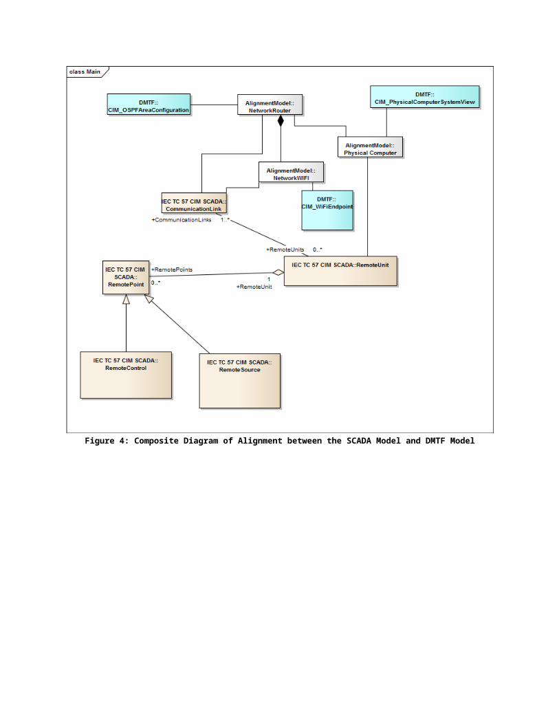
An example of a tool in the EMS that would benefit from inclusion of cyber security information is a coordinated cyber-physical alarm processor. The enhanced alarm processor is a suite of cyber-physical security evaluation applications that have the capability to identify cyber attack scenarios in the power system SCADA environment. The tool receives real-time feeds of cyber security and power system alarms, thus enabling the capability to correlate both streams of data to identify cyber attacks targeting power system operation. These messages are typically exchanged with geographically dispersed control centers through a complex networking infrastructure that is exposed to threat actors. It is possible that threat actors corrupt the integrity of legitimate monitoring messages sent from the substation to the control center by exploiting vulnerabilities in the communication channels. Figure 4 shows the specific links between the IEC TC57 CIM and DMTF information model for improved modeling of the telecommunications and computers used in SCADA systems. Secure message exchanges to the enhanced alarm processor, named STEVE, are presented via an interaction diagram shown in Figure 5 and described in Table 2.

Figure 4: Composite Diagram of Alignment between the SCADA Model and DMTF Model

Figure 5: Interaction Diagram: Enhanced Alarm Processor Message Exchanges
Table 2 below provides details on message exchanges in the enhanced alarm processing. Along with the message title, the table also identifies the data models used. We propose that enhanced alarm processing should be capable of processing messages from the DMTF, IEC TC57 CIM, and STIX. The DMTF provides information on SCADA network hardware and network configuration. The IEC TC57 CIM provides power system SCADA-specific data. STIX provides the capability to define cyber security-related information such as attack strategies. Some messages, as observed below, constitute data from more than one data model. The need for data model federation is further reinforced by such messages.
Table 2: Description of STEVE Message Exchanges
Message DMTF TC57 CIM STIX
SCADA_Alarms_Summary XCyber_Alarms_Summary X XVulnerabilities_Notification X XSys_Maintenance XCPS_Study_Request X
Message DMTF TC57 CIM STIX
State_Estimation_Request XState_Estimation_Reply XNetwork_Data_Request_1 X XNetwork_Data_Request_2 XLocal_Measurement_Request XSecurity_Info_Request X XCPS_Alarm_Measurements X X XCPS_Alarm_Cyber X X X
There must also be a defined process to verify the status of cyber equipment after a physical break in at a substation—a method to review all the set points, firmware versions, and firewall rules, etc. This procedure would accompany physical checks and repairs to substation physical equipment after a breach in order to certify that the substation is ready to resume normal operations.
4.0 Secure Implementation of CIM Exchanges
The CIM standards provide the semantic definitions and relationships (e.g., metadata) that allow instances of the metadata objects and relationships to be created in UML. In order to establish an interoperable information exchange, both the metadata definitions and instances need to be exchanged and agreed upon by the exchanging entities.
As an example, Figure 6 shows a subset of the UML regarding a power transformer. The UML defines that a power transformer is to be contained in a substation, can have a location, and can have a specific serial number.

Figure 6: Metadata Example for a Power Transformer
These definitions represent what could be exchanged, but do not state what specific data is exchanged. The specific information exchanged would contain the actual location, substation, and serial number for a particular power transformer. The metadata does not typically contain any significant information that requires cyber security protection (e.g., specific power transformer information). Therefore, the metadata files do not require cyber security protection during exchange, which is typically done through a variety of out-of-band file transfer mechanisms.
The standardization of how instance information is exchanged—known as serialization standardization—is also defined by the standards. There are two prevalent exchange serialization techniques used within CIM information exchanges: files and XSD-based messages. Similar to the metadata, these serialization standards define how to transfer information but do not define the specific instance information (e.g., a power transformer is installed in Substation A). As with the metadata, the standardized serialization definitions do not require cyber security protection and thus are transferred using a variety of out-of-band file transfer mechanisms.
The actual exchange technique (e.g., file transfer or XSD messages) varies based upon the business application domain in which the exchange is taking place. Files are typically moved, via FTP or other file transfer mechanisms, from the entity that stores the file (e.g., server) to a particular client requesting the file transfer (e.g., client) in a point-to-point fashion. Messages can be point-to-point (e.g., the message payload is sent to a particular destination) or point-to-multipoint (e.g., the message payload is sent to multiple destinations). The two typical implementations of point-to-multipoint exchanges are shown in Figure 7.

Figure 7: Implementation Methodologies for Point-to-Multipoint Exchanges
Methodology 1 shows a single application request being converted by a messaging engine (provider) into a sequence of two individual messages. Since the provider is part of the business application, this methodology creates two point-to-point exchanges.
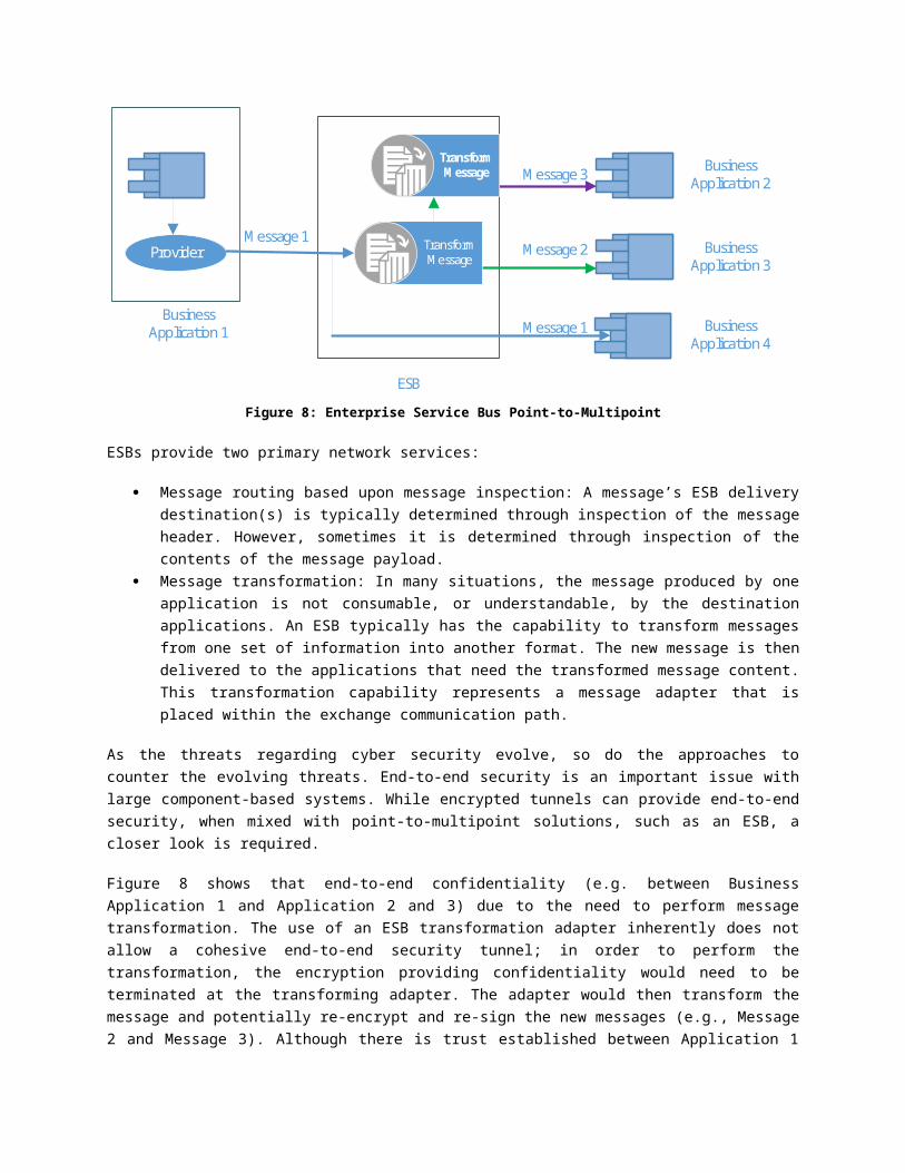
Methodology 2 utilizes the capabilities provided by other entities on the network path to deliver the single message produced by the messaging engine to multiple endpoints. Since the same message is delivered to multiple endpoints, this would be considered multicast communication where the business applications are in the same security group. However, since the CIM message transfers are web service or XSD-based, network multicasting is typically provided through an intervening Enterprise Service Bus (ESB), as shown in Figure 8.
Business Application 1
Business Application 2
Business Application 3
Provider
Message 1(App 1 to App 2)
Message 2(App 1 to App 3)
Business Application 1
Business Application 2
Business Application 3
Provider
Point-to-Multipoint (multiple point-to-point)
Point-to-Multipoint (multicast)
Network
Message 1
Message 1
Message 1
Methodology 1
Methodology 2
Business Application 1
Business Application 2
Business Application 3
Provider
ESB
Message 1
Message 3
Message 2TransformMessage
TransformMessage
Business Application 4
Message 1

Figure 8: Enterprise Service Bus Point-to-Multipoint
ESBs provide two primary network services:
Message routing based upon message inspection: A message’s ESB delivery destination(s) is typically determined through inspection of the message header. However, sometimes it is determined through inspection of the contents of the message payload.
Message transformation: In many situations, the message produced by one application is not consumable, or understandable, by the destination applications. An ESB typically has the capability to transform messages from one set of information into another format. The new message is then delivered to the applications that need the transformed message content. This transformation capability represents a message adapter that is placed within the exchange communication path.
As the threats regarding cyber security evolve, so do the approaches to counter the evolving threats. End-to-end security is an important issue with large component-based systems. While encrypted tunnels can provide end-to-end security, when mixed with point-to-multipoint solutions, such as an ESB, a closer look is required.
Figure 8 shows that end-to-end confidentiality (e.g. between Business Application 1 and Application 2 and 3) due to the need to perform message transformation. The use of an ESB transformation adapter inherently does not allow a cohesive end-to-end security tunnel; in order to perform the transformation, the encryption providing confidentiality would need to be terminated at the transforming adapter. The adapter would then transform the message and potentially re-encrypt and re-sign the new messages (e.g., Message 2 and Message 3). Although there is trust established between Application 1 and the ESB, the fact that the message was initiated by Application 1 is potentially lost when Messages 2 and 3 are delivered.
Digital signature technology is the mechanism to provide end-to-end identity establishment, authentication, and tamper detection. This methodology, when properly applied, protects all contents of the message payload as well as the message header. IEC TC57 Working Group 15 has established two basic technologies for digital signature key management: digital certificate-based signatures for point-to-point communications and Group Domain of Interpretation (GDOI) for point-to-multipoint communications. The GDOI approach allows multiple applications/providers to authenticate against a Key Distribution Center (KDC) as part of a group interested in exchanging information. The KDC authenticates the group members and supplies all group members with the same key material for encryption and signing. The GDOI methodology allows group members to be authenticated, but does not authenticate individual applications during the actual message exchange.
GDOI can also provide end-to-end confidentiality. Applying point-to-point methodologies requires establishing the equivalence of a chain of trust, and GDOI already establishes the trust of the group. However, GDOI does not provide information regarding the path the message traversed.
The general structure of an IEC TC57 Working Group 14 (WG14) style message is shown in Figure 9. It consists of an envelope that represents the technique being used to send the message. The actual WG14 message consists of a ns:Header and a ns:Payload. The figure also shows that the digital signature would apply to the entire WG14 message.

Figure 9: General structure example of WG14 message
Message exchanges using the IEC TC57 WG14 technique are most impacted by end-to-end security and the use of ESB technology incorporated within the end-to-end security framework.
In order for an ESB to perform rudimentary message routing, message header information needs to be unencrypted and contain enough information to allow the ESB to determine the destination(s) to which to deliver the messages. Payload-based topic routing may not be possible if end-to-end encryption is utilized.
If end-to-end confidentiality is provided by encrypting the payload, then intervening message transformation will not be possible.
If the ESB refactors the message, the signature and payload encryption will change. In this instance, the path of transformation may be important. Therefore, the ns:Header may need to be changed to allow multiple verb/noun combinations that are signed, within the ns:Header, in a hierarchical manner. This mechanism would allow the receiving application to authenticate the path of message transformation as well provide an end-to-end message authentication capability.
If the ESB transforms a non-WG14 style message into a WG14 style message, the first transformation needs to provide equivalent verb/noun information for the originator of the non-WG14 style message as well as its own information.
5.0 Conclusions
The CIM does indeed have cyber security uses; however, solutions created from the CIM still require the same attention to cyber security that any other solution requires. The CIM allows for standardized definitions of message content related to cyber security for the smart grid. The CIM provides a high fidelity model of the physical electrical grid. This article showed how the CIM could be use in concert with other domain models—such as cyber security or first responders—to create profiles that can provide comprehensive information about the event. This work is being extended to other business needs that require a multi-model profile. This article also discussed how to maintain confidentiality and integrity of the message data being exchanged in XSD messages derived from the CIM.
6.0 Further Readings
The following documents provide references to additional information regarding the topics covered in this article:
(Goodrich, 2014) M. Goodrich, “61968 – 9 Meter Reading and Control”, presentation given in CIM University at the CIM User’s Group Meeting, Oslo, Norway, June 2014. http://cimug.ucaiug.org/Meetings/Oslo2014/Supporting%20Documents/CIM%20University/04-61968-9%20Meter%20Reading%20and%20Control.pdf (accessed on 2015-09-07).
(Neumann et al., 2011) S. Neumann, M. Goodrich, L. Malesku, F. Wilhoit, "Enterprise Integration Using the IEC CIM", CIM Users Group Spring Meeting, Prague, Czech Republic, May 10–13, 2011.
(Neumann, Haynes and Viegut, 2012) S. Neumann, D. Haynes, T. Viegut, "Enterprise Integration of Metering Systems Using IEC 61968-9", DistribuTech 2012 session on Enterprise Integration and Asset Management, San Antonio, Texas, USA, January 24-26, 2012.http://uisol.com/new/wp-content/uploads/2015/08/DistribuTECH-2012-Scott-Neumann-IEC-61968-9-2nd-Edition-r2.pdf (accessed on 2015-08-24).
7.0 Authors
Paul Skare is with Pacific Northwest National Laboratory, Richland, WA, USA.Herbert Falk is with Systems Integration Specialists Company, Inc. (SISCO), Sterling Heights, MI, USAMark Rice is with Pacific Northwest National Laboratory, Richland, WA, USA