cyberknife at saint raphael’s campus_revb
TRANSCRIPT

CYBERKNIFE At Saint Raphael’s Campus
Presented by: Justin Vinci M.S. DABR

SUMMARY Cyberknife System Overview
Cyberknife Concept Cyberknife Components
Cyberknife Experience at SRC Tracking Modalities Collimation
Fixed Stereotactic Cones IRIS Variable aperture
Treatment Planning Optimization Dose Calculation
Physics QA

CYBERKNIFE SYSTEM OVERVIEW Cyberknife Concept
Robotic Radiosurgery System Non-coplanar beam arrangement
Theoretically able to achieve a better treatment plan Conformality Homogeneity Critical structure avoidance
Stereotactic alignment accuracy Room based stereotactic kV X-ray imaging system < 1 mm targeting accuracy
Inter and Intrafraction Motion Management kV X-rays taken throughout treatment Synchrony respiratory motion tracking

CYBERKNIFE SYSTEM OVERVIEW
Cyberknife Components Manipulator
KUKA robot with 6 axes of rotation < 0.2 mm Mechanical precision
Manual control with “teach pendant”
Programmable robot positions Linac
6 MV No flattening filter Dose Rate = 800 cGy/Min Sealed ion chambers (since 2010)
Collimation system 12 Fixed cones or IRIS variable
collimator Collimator exchange table

CYBERKNIFE SYSTEM OVERVIEW Cyberknife Components
Robocouch 6 degrees of motion
kV X-ray Target Location System Floor mounted flat panel imagers
Perkin Elmer ASi panels 1024 x 1024 pixels 41 x 41 cm physical dimensions
Ceiling mounted X-ray tubes Oil cooled 2.5 mm Al filtration up to 125 kV, 320 mA, 500 ms
Synchrony Respiratory Tracking System Ceiling mounted LED camera array
Treatment Planning System Multi-Plan V3.5

CYBERKNIFE SYSTEM OVERVIEW
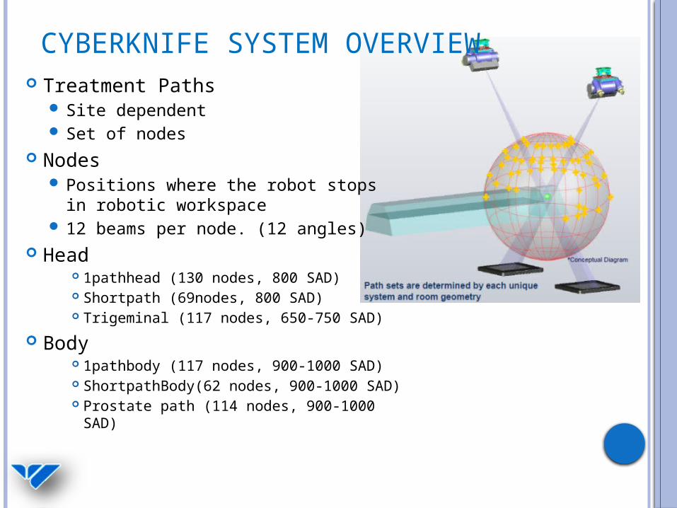
CYBERKNIFE SYSTEM OVERVIEW Treatment Paths
Site dependent Set of nodes
Nodes Positions where the robot stops in
robotic workspace 12 beams per node. (12 angles)
Head 1pathhead (130 nodes, 800 SAD) Shortpath (69nodes, 800 SAD) Trigeminal (117 nodes, 650-750 SAD)
Body 1pathbody (117 nodes, 900-1000 SAD) ShortpathBody(62 nodes, 900-1000 SAD) Prostate path (114 nodes, 900-1000 SAD)
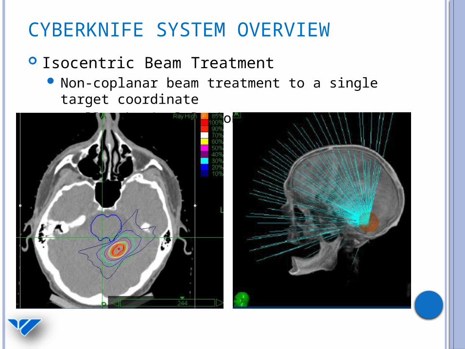
CYBERKNIFE SYSTEM OVERVIEW Isocentric Beam Treatment
Non-coplanar beam treatment to a single target coordinate
Small spherical lesions

CYBERKNIFE SYSTEM OVERVIEW Conformal Beam Treatment
Non-isocentric “Dose Painting” delivery Multiple target coordinates

CYBERKNIFE SYSTEM OVERVIEW

CYBERKNIFE EXPERIENCE AT SRC
Installed May 2008 Re-commissioned 2010 with IRIS upgrade
Total Intracranial Patients Treated 466Total Extracranial Patients Treated 272 TOTAL PATIENTS TREATED 738

CYBERKNIFE EXPERIENCE AT SRC
Installed May 2008 Re-commissioned 2010 with IRIS upgrade
AVM/AVOM 1 Breast Met to Brain 41
Trigeminal Neuralgia 62 Renal Met to Brain 12
Vestibular Schwannoma 39 Colon Met to Brain 8
Meningioma 85 Melanoma Met to Brain 6
Pituitary Adenoma 18 Ovarian Met to Brain 1
Glioblastoma 15 Other Metastatic Tumor to Brain 14
Craniopharyngioma 1 Glomus Tumor 3
Hemangioblastoma 2 Astrocytoma/Glioma/GBM 4
Schwannoma 8 Oligodendroglioma/Medulloblastoma 3
Other/Vas/Func Benign Tumors 1 Other Glial Tumors/Other/Unknown 1
Lung Met to Brain 141 Total Intracranial Patients Treated 466
Data Intracranial (5/2008 – 2/2013)

CYBERKNIFE EXPERIENCE AT SRC
Data Extracranial
C-spine 8
T-spine 36
L/S-spine 15
Lung 87
Liver 15
Pancreas 5
Head/Neck/ENT 12
Prostate 67
Nasopharynx 1
Other 26
Total Extracranial Patients Treated 272

TRACKING MODALITIES
6D Skull Cranial Lesions Brain Mets Trigeminal Neuralgia Benign Meningiomas
Fiducial Tracking Body Prostate
Synchrony Fiducial Tracking
with respiratory motion correction
Lung, Liver
X-sight Spine S,L,T,C Spine
Anything < 5 cm from spine
X-sight Lung Lesions >1.5 cm in
periphery of lung
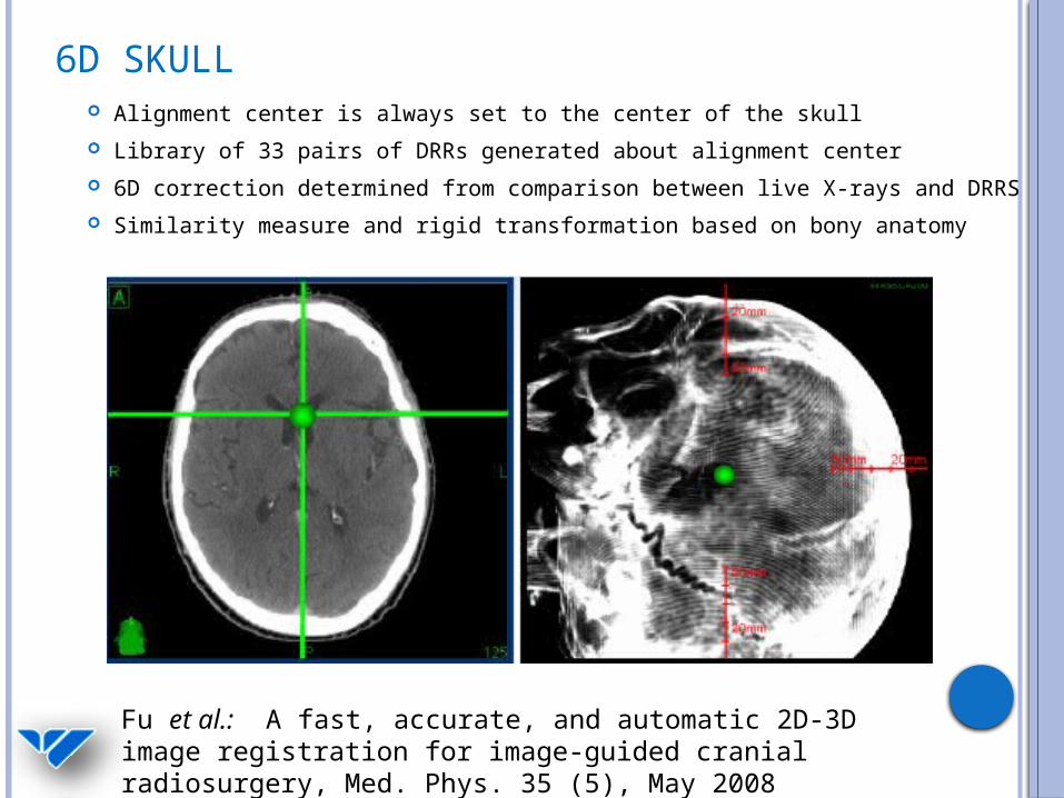
6D SKULL Alignment center is always set to the center of the skull Library of 33 pairs of DRRs generated about alignment center 6D correction determined from comparison between live X-rays and
DRRS Similarity measure and rigid transformation based on bony anatomy
Fu et al.: A fast, accurate, and automatic 2D-3D image registration for image-guided cranial radiosurgery, Med. Phys. 35 (5), May 2008

6D SKULL
6D couch correction is calculated based on kV X-rays
Robocouch couch
automatically moves to the correct position
The Cyberknife robot adjusts beam targeting during treatment based intra-fraction images (limits: 10 mm, 1.5 degrees)

FIDUCIAL TRACKING
Several fiducials surgically implanted in or nearby the tumor
6D tracking requires at least 3 fiducials 20 mm separation, 15°, non-co-linear, < 5 cm from target
We typically use 0.8 x 3 mm coupled gold markers 18 gauge needle Fiducials are identified on the CT in MultiPlan and
used for alignment
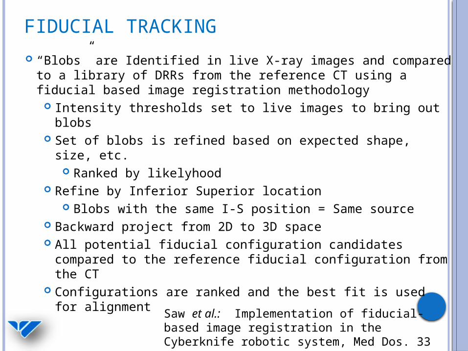
FIDUCIAL TRACKING “Blobs” are Identified in live X-ray images and compared to a
library of DRRs from the reference CT using a fiducial based image registration methodology
Intensity thresholds set to live images to bring out blobs Set of blobs is refined based on expected shape, size, etc.
Ranked by likelyhood Refine by Inferior Superior location
Blobs with the same I-S position = Same source Backward project from 2D to 3D space All potential fiducial configuration candidates compared to
the reference fiducial configuration from the CT Configurations are ranked and the best fit is used for
alignment
Saw et al.: Implementation of fiducial-based image registration in the Cyberknife robotic system, Med Dos. 33 (2), 2008

FIDUCIAL TRACKING
3 or more fiducial markers are placed inside the tumor with adequate separation
Fiducial pattern is recognized by the Cyberknife imaging system. Marker locations in the Live X-ray images are compared to expected locations. The robotic couch automatically repositions the patient.
The Cyberknife makes 6D (X,Y,Z; α,θ,φ) corrections to beam targeting using a rigid transformation algorithm
Live X-ray images taken during the treatment allows for semi-continuous monitoring of intra-fraction motion (when not using Synchrony)
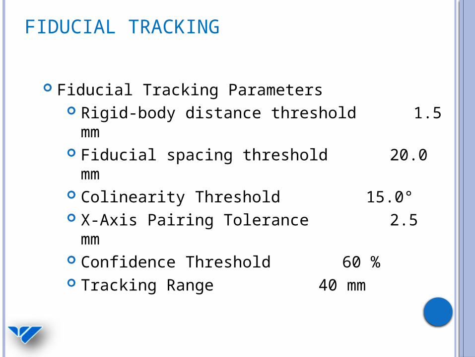
FIDUCIAL TRACKING
Fiducial Tracking Parameters Rigid-body distance threshold 1.5
mm Fiducial spacing threshold
20.0 mm Colinearity Threshold 15.0° X-Axis Pairing Tolerance 2.5
mm Confidence Threshold 60 % Tracking Range 40 mm
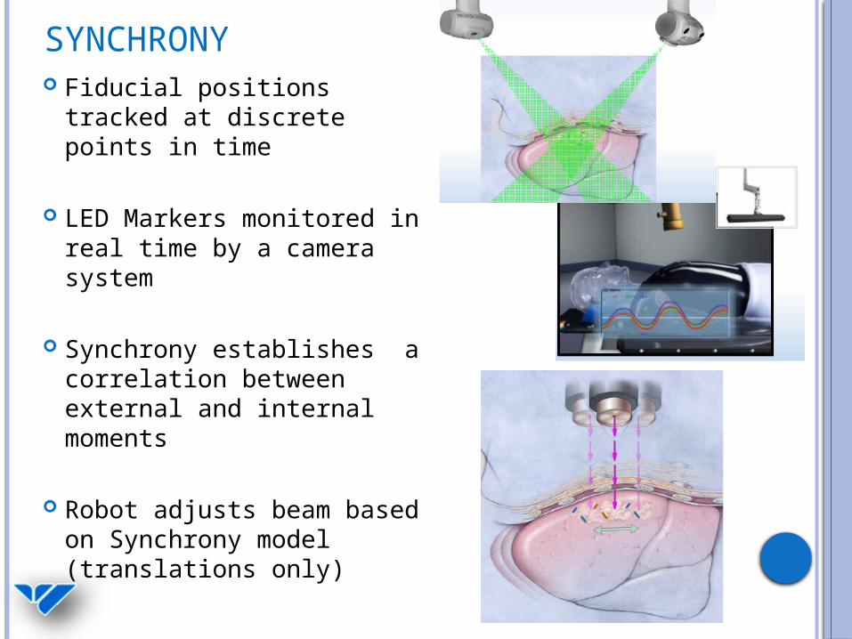
SYNCHRONY Fiducial positions tracked
at discrete points in time
LED Markers monitored in real time by a camera system
Synchrony establishes a correlation between external and internal moments
Robot adjusts beam based on Synchrony model (translations only)

SYNCHRONYBreathing Trace
Correlation Graphs
Coverage of Breathing Cycle
Correlation Error Graph
Nioutsikou et al.: Dosimetric investigation of lung tumor motion compensation with a robotic respiratory tracking system: An experimental study, Med. Phys. 35 (4), April 2008 Pepin et al.: Correlation and prediction uncertainties in the Cyberknife Synchrony respiratory tracking system, Med. Phys. 38 (7), July 2011
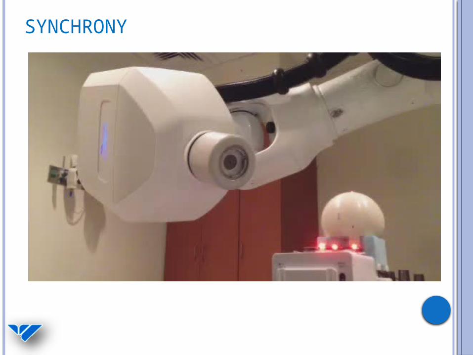
SYNCHRONY

XSIGHT SPINE Inherent problems aligning spinal anatomy:
Vertebrae can move independent of one another
Rigid transformation may be invalid Risks associated with surgical fiducial
placement
Xsight spine solution: Deformable registration technique for spine alignment

XSIGHT SPINE Image enhancement
Enhance skeletal structures, suppress soft tissue DRR generation (17 pairs of DRRs) ROI placement
Maximum bone information Skeletal mesh overlayed on spine
2D-3D registration Spatial transformation base on similarity
measure Local displacement field calculated at each node
(81) 3D target location calculated
Maucevic et al.: Technical description, phantom accuracy, and clinical feasibility for fiducial –free frameless real-time image guided spinal radiosurgery, J. Neurosurg Spine, 5 October 2006 Furweger et al.: Advances in fiducial-free image-guidance for spinal radiosurgery with Cyberknife – a phantom study, J. Applied Clinical Med. Phys. 12, (2), Spring 2011

XSIGHT SPINE
Difference in spinal anatomy detected between acquired Live X-ray images and planned DRR images
6D Treatment Couch corrections (X,Y,Z; α,θ,φ) are applied for initial setup.
The Cyberknife robot adjusts beam targeting during treatment based intra-fraction images
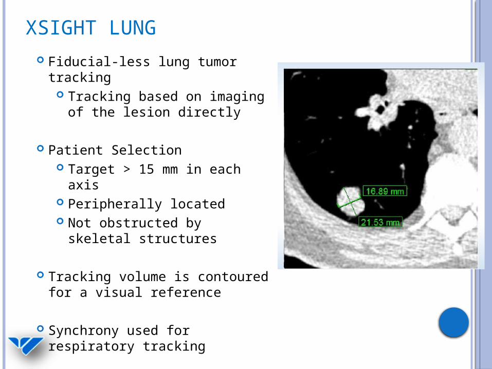
XSIGHT LUNG Fiducial-less lung tumor
tracking Tracking based on imaging
of the lesion directly
Patient Selection Target > 15 mm in each
axis Peripherally located Not obstructed by skeletal
structures
Tracking volume is contoured for a visual reference
Synchrony used for respiratory tracking

XSIGHT LUNG Fiducial-less lung tumor
tracking Tracking based on imaging
of the lesion directly
Patient Selection Target > 15 mm in each
axis Peripherally located Not obstructed by skeletal
structures
Tracking volume is contoured for a visual reference
Synchrony used for respiratory tracking

XSIGHT LUNG Fiducial-less lung tumor
tracking Tracking based on imaging
of the lesion directly
Patient Selection Target > 15 mm in each
axis Peripherally located Not obstructed by skeletal
structures
Tracking volume is contoured for a visual reference
Synchrony used for respiratory tracking
XSIGHT LUNG
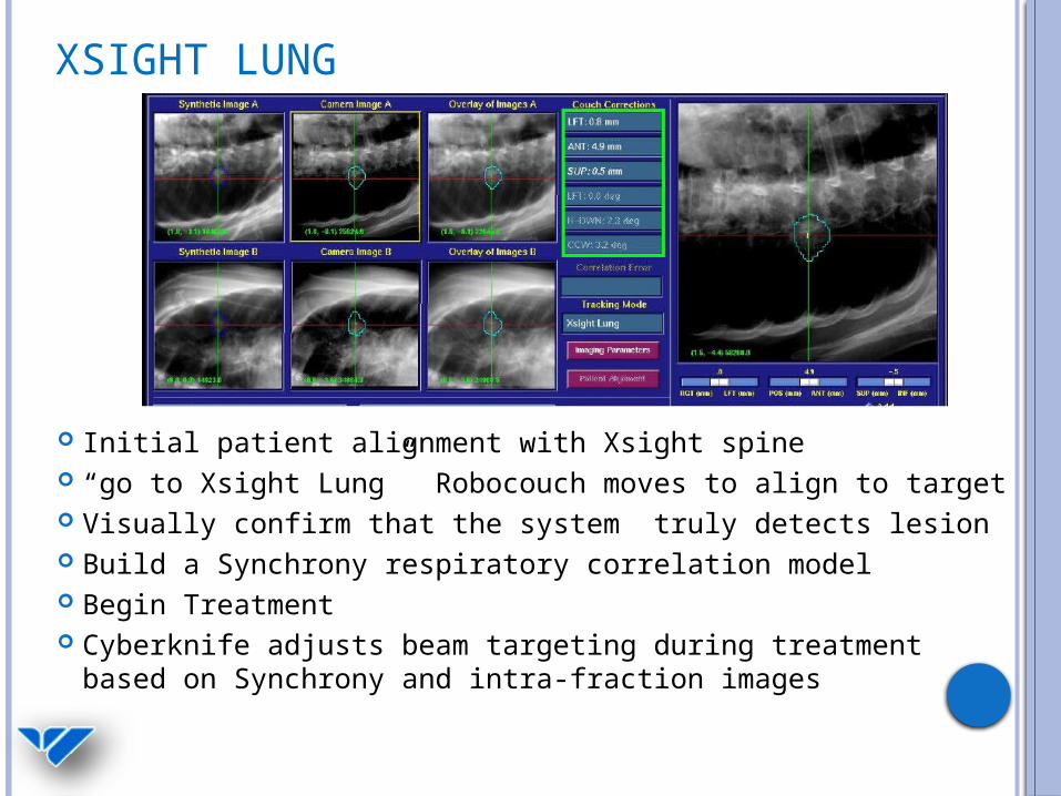
Initial patient alignment with Xsight spine “go to Xsight Lung” Robocouch moves to align to target Visually confirm that the system truly detects lesion Build a Synchrony respiratory correlation model Begin Treatment Cyberknife adjusts beam targeting during treatment
based on Synchrony and intra-fraction images

COLLIMATION TYPES
Stereotactic cone sizes: 5, 7.5, 10, 12.5, 15 20, 25, 30, 35, 40, 50, 60 mm (defined at 80 cm)
Variable aperture sizes: 5, 7.5, 10, 12.5, 15, 20, 25, 30, 35, 40, 50, 60 mm (defined at 80 cm)
Fixed IRIS

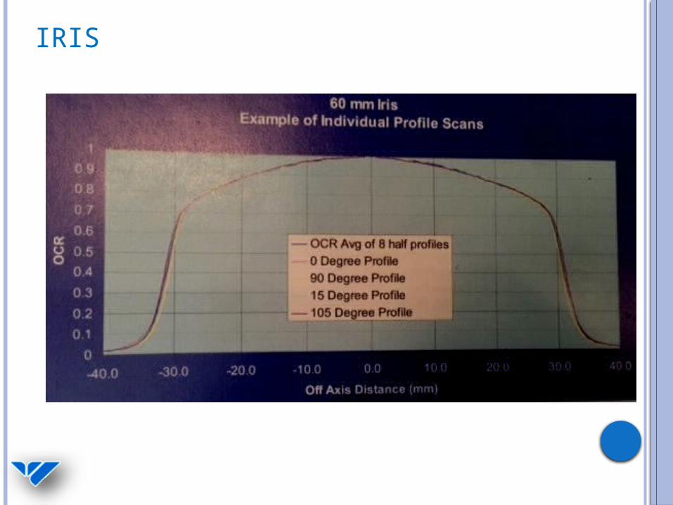
IRIS
2 banks of 6 tungsten blocks Dodocegonal Beam Penumbra periodicity
30° at 80% 60° at low isodoses (<20%)
IRIS

IRIS

BEAM DATA TPR (Coll, d)

BEAM DATA OCR (Coll, d, r)
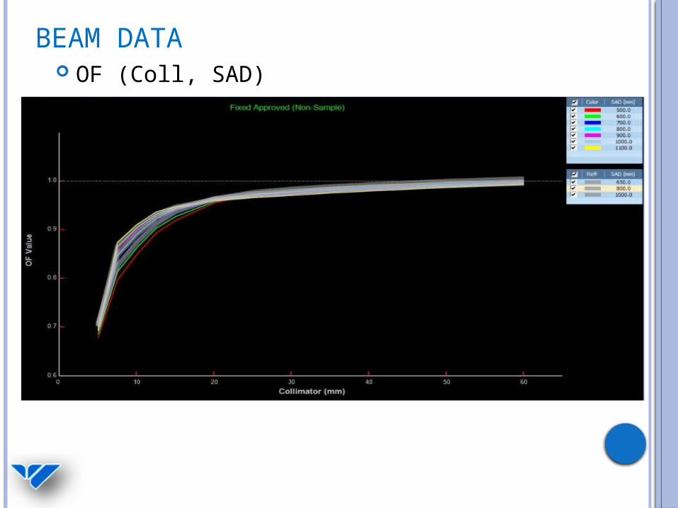
BEAM DATA OF (Coll, SAD)

TREATMENT PLANNING
MultiPlan Version 3.5 Import Image Sets for Planning
CT, MR, PET Fuse and create contours
Define parameters Tracking method Collimation Conformal vs. Isocentric Pathset
Optimization and beam reduction Dose Calculation
Ray trace/Monte Carlo
OPTIMIZATION
MU/beam, MU/node Create shells VOI Limits
Set global max doses for structures Objective Steps
Target Optimize Minimum Dose Optimize Coverage Optimize Homogeneity
Critical Structures Optimize Max Dose Optimize Mean Dose

DOSE CALCULATIONS – RAY TRACING Calibration Conditions:
dmax = 15 mm 800 SAD 60 mm Fixed Collimator
),(),(800
),,()/(2
800 SADcollDMDFSTPRSAD
DRcollOCRMUD effeff
SAD
RR SAD
800800
800
SADCollFS
)800,60()15,60(800
800)15,0,60()/(
2
DMTPROCRMUD
11111)/( 2 MUD
800 mm SAD
cGy/MU

DOSE CALCULATIONS – MONTE CARLO Ray Trace overpredicts dose to PTV Monte Carlo simulates particle transport and
energy deposition in the patient Much more accurate dose in presence of
heterogeneities
Deng et al.: Commissioning 6 MV photon beams of a stereotactic radiosurgery system for Monte Carlo treatment planning, Med Phys. 30 (12), December 2003
Wilcox et al.: Comparison of planned dose distributions calculated by monte carlo and ray-trace algorithms for the treatment of lung tumors with Cyberknife: A preliminary study in 33 patients, Int. J. Radiation Oncology Biol. Phys. 2009 Wilcox et al.: Stereotactic radiosurgery-radiotherapy: Should Monte Carlo treatment planning be used for all sites? Practical Radiation Oncology (2011)1, 25
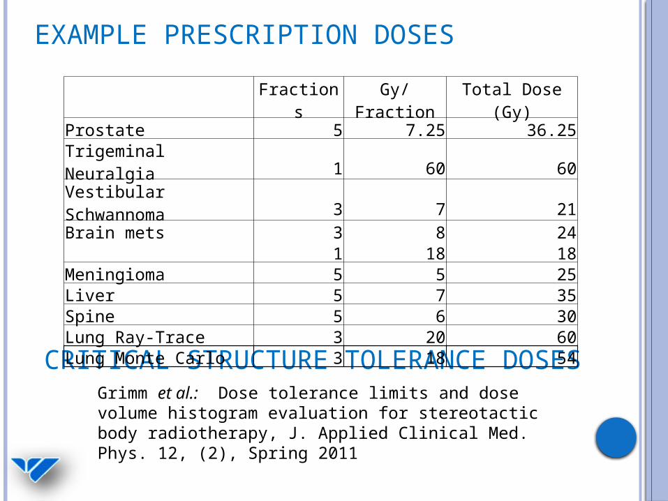
EXAMPLE PRESCRIPTION DOSES
Grimm et al.: Dose tolerance limits and dose volume histogram evaluation for stereotactic body radiotherapy, J. Applied Clinical Med. Phys. 12, (2), Spring 2011
CRITICAL STRUCTURE TOLERANCE DOSES
Fractions Gy/Fraction Total Dose (Gy)Prostate 5 7.25 36.25Trigeminal Neuralgia 1 60 60Vestibular Schwannoma 3 7 21Brain mets 3 8 24 1 18 18Meningioma 5 5 25Liver 5 7 35Spine 5 6 30Lung Ray-Trace 3 20 60Lung Monte Carlo 3 18 54
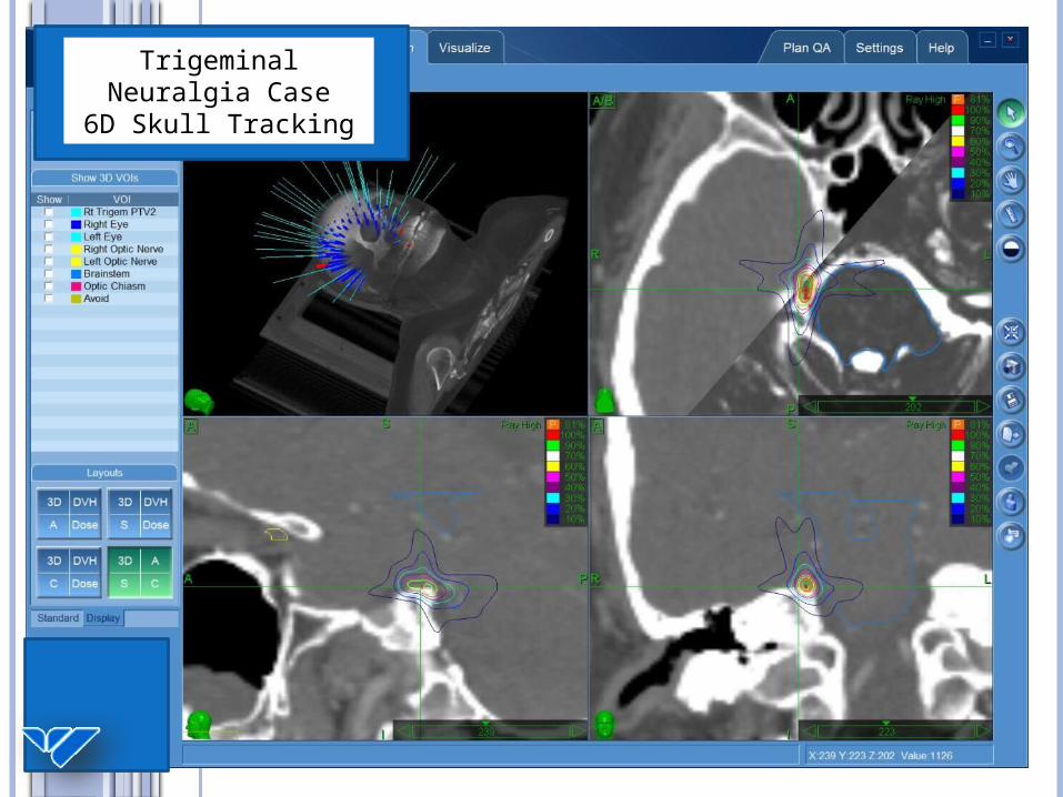
Trigeminal Neuralgia Case
6D Skull Tracking

Spine CaseXsight Spine
Tracking

CYBERKNIFE SYSTEM OVERVIEW
Proximity Detection Program (PDP)Site
head body
Fixed
Dynamic

PHYSICS QA
AQA End to End Tests (E2E)
Head phantom, Ballcube II Spine, mini-ballcube Synchrony motion phantom Xsight Lung motion phantom
Dose Output, TG-51 Daily Monthly
Patient Specific QA (PSQA) IRIS aperture size check

AQA Daily QA check of robot
mastering Winston Lutz-ish
Concentric circles AP and Lateral beams
targeted to metal sphere Aligned with fiducial
tracking
Example EBT3 film
Example thresholded images
AQA film phantom
0°
90°

E2E
End to End test Center ball contoured on CT 70% isodose is centered on
the ball in Multiplan (< 0.1 mm)
Analysis software provided by Accuray
Delta-Man Adjustments 6D Skull Fiducial Xsight spine

DOSE CALIBRATION AND QA
TG-51 in water Atypical TG-51 conditions
Determination of kq Ref: Toru et al.: Reference
dosimetry condition and beam quality correction factor for Cyberknife beam, Med Phys. 35 (10), October 2008
Monthly calibration check A14 in solid water phantom
Daily Birdcage output check

PATIENT SPECIFIC QA
Patient-Specific QA performed for nearly every patient
Patient’s treatment plan (dose rescaled) delivered to a film-measurement phantom
Delivered dose is analyzed in RIT and compared to the prescribed plan by physics staff and approved prior to treatment
Verification of Cyberknife targeting and dose delivery accuracy
Gamma criteria:
5% 1 mm agreement
3% 1 mm in the future with improved film techniques Laser-Cut EBT3 gafchromic
film
CIRS Anthropomorphic head phantom with Ballcube II
film insert

Planned Dose
Delivered Dose
Legend
Dose falloff near
brainstemPrescription Isodose line
Trigeminal Neuralgia Case
6D Skull Tracking

Planned Dose
Delivered Dose
Legend
Dose falloff near spinal cord verified
Spine CaseXsight Spine
Tracking

Planned Dose
Delivered Dose
Legend
Dose falloff near spinal cord verified
Spine CaseXsight Spine
Tracking

REFERENCESToru et al.: Reference dosimetry condition and beam quality correction factor for Cyberknife beam, Med Phys. 35 (10), October 2008 Deng et al.: Commissioning 6 MV photon beams of a stereotactic radiosurgery system for Monte Carlo treatment planning, Med Phys. 30 (12), December 2003 Nioutsikou et al.: Dosimetric investigation of lung tumor motion compensation with a robotic respiratory tracking system: An experimental study, Med. Phys. 35 (4), April 2008 Sharma et al.: Commissioning and acceptance testing of a Cyberknife linear accelerator, J. Applied Clinical Med. Phys. 8, (3), Summer 2007 Saw et al.: Implementation of fiducial-based image registration in the Cyberknife robotic system, Med Dos. 33 (2), 2008 Maucevic et al.: Technical description, phantom accuracy, and clinical feasibility for fiducial –free frameless real-time image guided spinal radiosurgery, J. Neurosurg Spine, 5 October 2006

REFERENCESFurweger et al.: Advances in fiducial-free image-guidance for spinal radiosurgery with Cyberknife – a phantom study, J. Applied Clinical Med. Phys. 12, (2), Spring 2011 Grimm et al.: Dose tolerance limits and dose volume histogram evaluation for stereotactic body radiotherapy, J. Applied Clinical Med. Phys. 12, (2), Spring 2011 Pepin et al.: Correlation and prediction uncertainties in the Cyberknife Synchrony respiratory tracking system, Med. Phys. 38 (7), July 2011 Wilcox et al.: Comparison of planned dose distributions calculated by monte carlo and ray-trace algorithms for the treatment of lung tumors with Cyberknife: A preliminary study in 33 patients, Int. J. Radiation Oncology Biol. Phys. 2009 Wilcox et al.: Stereotactic radiosurgery-radiotherapy: Should Monte Carlo treatment planning be used for all sites? Practical Radiation Oncology (2011)1, 25 Chang et al.: An analysis of the accuracy of the CyberKnife: A robotic frameless stereotactic radiosurgical system, Neurosurgery 52(1)2003

REFERENCES Fu et al.: A fast, accurate, and automatic 2D-3D image registration for image-guided cranial radiosurgery, Med. Phys. 35 (5), May 2008 Fu et al.: Fiducial-free Lung Tumor Tracking for Cyberknife Radiosurgery, I.J. Radiation Oncology Biol. Phys. 72 (1), 2979, 2008 Adler, J.R., Chang, S.D., Murphy, M.J., Doty, J., Geis, P., & Hancock,S.L. (1997). The CyberKnife: A frameless robotic system for radiosurgery. Stereotactic and Functional Neurosurgery, 69(1–4 Pt. 2),124–128.
Additional Information and Images taken from:Accuray Physics Essentials GuideAccuray Treatment Planning ManualAccuray Treatment Planning ManualTechnical Training for Radiation TherapistsAccuray Technical Training for Physicians: Full Body Course

ACKNOWLEDGEMENTS
Thanks to Saint Raphael’s Cyberknife Team – Physics, Dosimetry, and Radiation Therapy staff, and the Smilow Physics group for having me.