cybersecurity vulnerability analysis of the plc prime standard
TRANSCRIPT

Research ArticleCybersecurity Vulnerability Analysis of the PLCPRIME Standard
Miguel Seijo Simó, Gregorio López López, and José Ignacio Moreno Novella
Universidad Carlos III de Madrid, Madrid, Spain
Correspondence should be addressed to Miguel Seijo Simo; [email protected]
Received 20 February 2017; Accepted 18 May 2017; Published 5 July 2017
Academic Editor: Sherali Zeadally
Copyright © 2017 Miguel Seijo Simo et al. This is an open access article distributed under the Creative Commons AttributionLicense, which permits unrestricted use, distribution, and reproduction in any medium, provided the original work is properlycited.
Security in critical infrastructures such as the power grid is of vital importance. The Smart Grid puts power grid classical securityapproach on the ropes, since it introduces cyberphysical systems where devices, communications, and information systemsmust beprotected. PoweRline Intelligent Metering Evolution (PRIME) is a Narrowband Power-Line Communications (NB-PLC) protocolwidely used in the last mile of Advanced Metering Infrastructure (AMI) deployments, playing a key role in the Smart Grid.Therefore, this work aims to unveil the cybersecurity vulnerabilities present in PRIME standard, proposing solutions and validatingand discussing the results obtained.
1. Introduction
The Smart Grid represents a revolution especially at distri-bution and customer levels, bringing monitoring and controlcapabilities, traditionally available up to the primary substa-tions, down to the secondary substations and beyond. As aresult, the number of devices to be monitored and controlledincreases dramatically. Therefore, deploying accurate androbustAdvancedMetering Infrastructures (AMIs) is a criticalstep towards making Smart Grids fully operational.
In the scope of Smart Grids, AMIs are systems installedby the Distribution System Operators (DSOs) in the powergrid which are used for measuring, collecting, and analyzingthe energy consumed and/or generated by the clients. Inorder to do so, they communicate with metering devices(i.e., smart meters) to retrieve the consumption/generationdata. The elements involved in the AMI include the meteringdevices, communication protocols, consumer energy displaysand controllers, customer systems, Meter Data Management(MDM) software, and supplier business systems. AMIs arebeing widely established worldwide, especially in Europe,where the investment forecast goes up to 45 B€ for thedeployment of 200M smart meters before 2020 [1]. Onlyin Spain, all the metering infrastructure will be replaced
with smart meters by 2018, which means a deployment ofapproximately 30M meters [2].
Information and Communications Technologies (ICTs)play a key role in AMI, which brings many advantages butalso challenges for DSOs, being specially relevant the onesrelated to security and privacy. Attacks to critical infras-tructures such as the power grid are specially dangerous,meaning a major impact on health, security, and economicwelfare of the citizens or on the effective operation of thecountries where this attacks are performed [3]. These attacksare especially attractive from an economic point of view (e.g.,manipulating billing data), to obtain data that may revealsensitive information or with terrorist purposes (e.g., to causeblackouts). Despite the novelty of these technologies, thereare already examples illustrating the interest on attackingAMI infrastructures, such as the Malta incident [4], wheremore than a thousand smart meters were compromisedbetween 2011 and 2012, incurring a power theft worth 30M€.
Therefore, government authorities and competent bodiesare takingmeasures to protect AMI deployments from cyber-attacks. Thus, the European recommendation on Smart Gridsystems deployment emphasises security and privacy aspects[5]. In the same way, in USA, cybersecurity also represents amajor issue in this topic, in which different regulations from
HindawiSecurity and Communication NetworksVolume 2017, Article ID 7369684, 18 pageshttps://doi.org/10.1155/2017/7369684
2 Security and Communication Networks
(2)
(1)
(3)
(<15 KV)Smart meters
(<15 KV)Smart meters
(<15 KV)Smart meters
Last mile(PRIME, Zigbee mesh, etc.)
Last mile(PRIME, Zigbee mesh, etc.)
(Secondary substation)Data concentrator
(Secondary substation)Data concentrator
(Primary substation)Gateway
Informationsystems
BPL
GPRS/UMTS/ADSL
GPRS/UMTS
GPRS/UMTS/ADSL/�ber
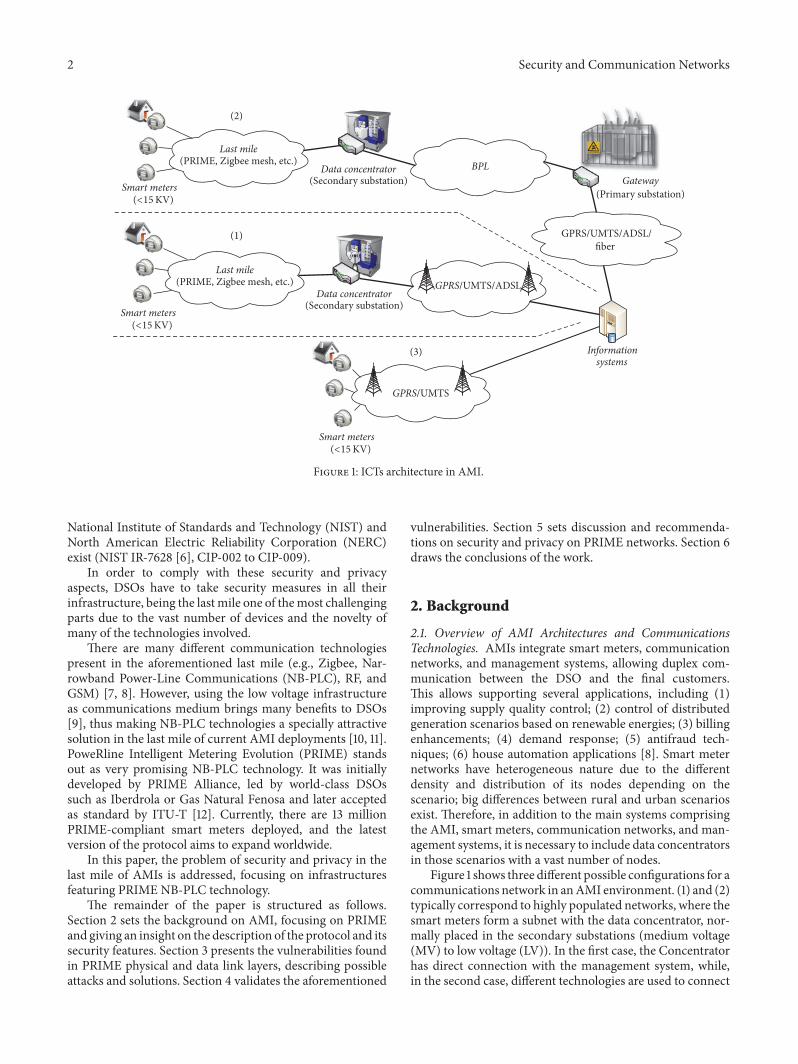
Figure 1: ICTs architecture in AMI.
National Institute of Standards and Technology (NIST) andNorth American Electric Reliability Corporation (NERC)exist (NIST IR-7628 [6], CIP-002 to CIP-009).
In order to comply with these security and privacyaspects, DSOs have to take security measures in all theirinfrastructure, being the last mile one of themost challengingparts due to the vast number of devices and the novelty ofmany of the technologies involved.
There are many different communication technologiespresent in the aforementioned last mile (e.g., Zigbee, Nar-rowband Power-Line Communications (NB-PLC), RF, andGSM) [7, 8]. However, using the low voltage infrastructureas communications medium brings many benefits to DSOs[9], thus making NB-PLC technologies a specially attractivesolution in the last mile of current AMI deployments [10, 11].PoweRline Intelligent Metering Evolution (PRIME) standsout as very promising NB-PLC technology. It was initiallydeveloped by PRIME Alliance, led by world-class DSOssuch as Iberdrola or Gas Natural Fenosa and later acceptedas standard by ITU-T [12]. Currently, there are 13 millionPRIME-compliant smart meters deployed, and the latestversion of the protocol aims to expand worldwide.
In this paper, the problem of security and privacy in thelast mile of AMIs is addressed, focusing on infrastructuresfeaturing PRIME NB-PLC technology.
The remainder of the paper is structured as follows.Section 2 sets the background on AMI, focusing on PRIMEand giving an insight on the description of the protocol and itssecurity features. Section 3 presents the vulnerabilities foundin PRIME physical and data link layers, describing possibleattacks and solutions. Section 4 validates the aforementioned
vulnerabilities. Section 5 sets discussion and recommenda-tions on security and privacy on PRIME networks. Section 6draws the conclusions of the work.
2. Background
2.1. Overview of AMI Architectures and CommunicationsTechnologies. AMIs integrate smart meters, communicationnetworks, and management systems, allowing duplex com-munication between the DSO and the final customers.This allows supporting several applications, including (1)improving supply quality control; (2) control of distributedgeneration scenarios based on renewable energies; (3) billingenhancements; (4) demand response; (5) antifraud tech-niques; (6) house automation applications [8]. Smart meternetworks have heterogeneous nature due to the differentdensity and distribution of its nodes depending on thescenario; big differences between rural and urban scenariosexist. Therefore, in addition to the main systems comprisingthe AMI, smart meters, communication networks, and man-agement systems, it is necessary to include data concentratorsin those scenarios with a vast number of nodes.
Figure 1 shows three different possible configurations for acommunications network in anAMI environment. (1) and (2)typically correspond to highly populated networks, where thesmart meters form a subnet with the data concentrator, nor-mally placed in the secondary substations (medium voltage(MV) to low voltage (LV)). In the first case, the Concentratorhas direct connection with the management system, while,in the second case, different technologies are used to connect

Security and Communication Networks 3
Table 1: Main PRIME features for v1.3.6 and v1.4 [20].
Layer Feature PRIME V1.3.6 PRIME V1.4
PHYFrequency band CENELEC band (3–95 kHz) FCC vand (10–490 kHz)
Data rate Up to 130 kbps Up to 1028.8 kbpsRobust mode No Repetition coder
MAC Network formation Beacon discovery, automatic promotion Beacon discovery (longer), automatic promotionKeep-alive monitoring Yes Yes (with link quality info)
these concentratorswith themanagement systemgateway. (3)is typically used in scenarios with a smaller number of nodeswhich are geographically dispersed, all of them being directlyconnected to the management system.
As it can be observed in Figure 1, the architecture istree-shaped (except for the smart meters, which can forma mesh network), where every branch represents a differentsubnet, thus making possible the combination of differentcommunication technologies in the same scenario. In theso-called last mile, covering from the smart meters to thesecondary substation, the most deployed technologies arethose not requiring deployment of new communicationchannels and featuring self-configuration network mecha-nisms and low cost (e.g., Zigbee mesh or NB-PLC). Onthe other hand, the main requirements for communicationtechnologies between the substations and the managementsystems are robustness, long range, and higher bit rates, fiber,xDSL, cellular technologies, or Broadband PowerLine (BPL)communications being the most deployed technologies.
In AMI scenarios, both the communication architecturesand technologies depend on many different factors, such asthe characteristics of the infrastructure, regulations to beapplied, or the applications to be supported. This generatesbroad differences in the different deployments worldwide.In Europe, for example, AMI deployments are oriented toprovide consumption/generation measurements to the clientaiming energy savings as well as providing remote controland measurements to the DSO, as stated in the Europeanrecommendation 2012/148/UE [5]. This recommendationalso addresses cybersecurity and privacy in smart metersystems, focusing on privacy issues. In USA, however, theapplications supported by AMI deployments are extendedwith new features, such as blackout, fraud, and nontech-nical losses detection, quality assurance, prepaid interfaces,demand response (DR), and home automation applications.Regarding cybersecurity recommendations, NIST directivesaddress security and privacy as well, focusing on securityissues [6].
In order to ensure security and privacy in AMI deploy-ments, every part of the architecture must be protected.However, the communications between the substations andthe management systems are more centralized and mostlybased on IP [9],making it easier to adapt existing security andprivacy solutions. On the other hand, the last mile features avast number of embedded terminal devices and a variety ofnetwork technologies that represent a broad research field interms of cybersecurity and are more difficult to be physicallyprotected.
Application layer (e.g., DLMS/COSEM)
IEC-432
PRIME convergence
PRIME link
PRIME Phy
Figure 2: Protocol stack in AMI scenarios based on PRIME.
Among the different last-mile communication technolo-gies, we can find cellular, wireless mesh (e.g., Zigbee orRF-Mesh), and NB-PLC. Cellular is the most expensivesolution, but its performance and reliability make it anoption where other solutions cannot be deployed. Wirelessmesh technologies are mature, reliable, and more suitablefor low density areas such as rural areas and villages. NB-PLC is cheap, fairly reliable, and suitable for dense areassuch as cities. While RF-Mesh and Zigbee are widely usedin the United States [8], NB-PLC technologies are winningmomentum worldwide, especially in Europe [13].
Among the different NB-PLC standards, G3, Meters andMore, and PRIME are largely deployed in Europe [13], wherePRIME started its worldwide expansion in the new version ofthe standard, by not only supporting European CENELEC-Aband, but also expanding to FCC and ARIB regulated bandsfor USA and Japan, respectively [14].
This work focuses on the vulnerability analysis of thephysical and link layers of the protocol stack present inAMI scenarios based on PRIME NB-PLC networks, whichis represented in Figure 2.
2.2. PRIME Description. PRIME is a NB-PLC technologydeveloped by the PRIME Alliance, although version 1.3.6of the physical (PHY), media access control (MAC), andconvergence layers of PRIME has been also accepted asstandard by the ITU-T [12]. Version 1.4was released at the endof 2014, including additional features, although this sectionfocuses on version 1.3 as it is the version present in most ofthe equipment deployed in the field. Table 1 summarizes themain differences between the aforementioned versions of theprotocol.
4 Security and Communication Networks
Reset
DisconnectedRegister
Unregister Unregister
Terminal Promote Switch
Demote
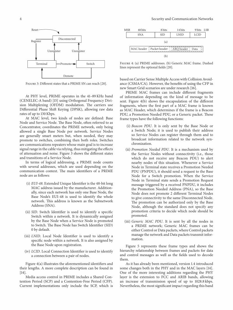
Figure 3: Different states that a PRIME SN can reach [20].
At PHY level, PRIME operates in the 41–89KHz band(CENELEC-A band) [15] using Orthogonal Frequency Divi-sion Multiplexing (OFDM) modulation. The carriers useDifferential Phase Shift Keying (DPSK), allowing raw datarates of up to 130Kbps.
At MAC level, two kinds of nodes are defined: BaseNode and Service Node. The Base Node, often referred to asConcentrator, coordinates the PRIME network, only beingallowed a single Base Node per network. Service Nodesare generally smart meters but, when needed, they maypromote to switches, combining then both roles. Switchesare communications repeaters whose main goal is to increasesignal range in the cable via relying, thusmitigating the effectsof attenuation and noise. Figure 3 shows the different statesand transitions of a Service Node.
In terms of logical addressing, a PRIME node countswith several addresses, which are used depending on thecommunication context. The main identifiers of a PRIMEnode are as follows:
(i) EUI-48. Extended Unique Identifier is the 48-bit longMAC address issued by the manufacturer. Addition-ally, since each network has only one Base Node, theBase Node’s EUI-48 is used to identify the wholenetwork. This address is known as the SubnetworkAddress (SNA).
(ii) SID. Switch Identifier is used to identify a specificSwitch within a network. It is dynamically assignedby the Base Node when a Service Node is promotedto Switch. The Base Node has Switch Identifier (SID)0 by default.
(iii) LNID. Local Node Identifier is used to identify aspecific node within a network. It is also assigned bythe Base Node upon registration.
(iv) LCID. Local Connection Identifier is used to identifya connection between a pair of nodes.
Figure 4(a) illustrates the aforementioned identifiers andtheir lengths. A more complete description can be found in[14].
Media access control in PRIME includes a Shared Con-tention Period (SCP) and a Contention-Free Period (CFP).Current implementations only include the SCP, which is
MSB LSBSNA SID LNID LCID
9 bits14 bits8 bits48 bits
(a)
MAC header Packet header ARQ header Data
(b)
Figure 4: (a) PRIME addresses. (b) Generic MAC frame. Dashedlines represent the optional fields [20].
based onCarrier SenseMultiple Access with CollisionAvoid-ance (CSMA/CA). However, the benefits of using the CFP innew Smart Grid scenarios are under research [16].
PRIME MAC frames can include different fragmentsof information depending on the kind of message to besent. Figure 4(b) shows the encapsulation of the differentfragments, where the first part of a MAC frame is knownas MAC Header, which determines if the frame is a BeaconPDU, a Promotion Needed PDU, or a Generic packet. Theseframe types have the following functions:
(i) Beacon PDU. It is only sent by the Base Node ora Switch Node; it is used to publish their addressso Service Nodes can register through them and tobroadcast information related to the network syn-chronization.
(ii) Promotion Needed PDU. It is a mechanism used bythe Service Nodes without connectivity (i.e., thosewhich do not receive any Beacon PDU) to alertnearby nodes of this situation. Whenever a ServiceNode in Terminal state receives a Promotion NeededPDU (PNPDU), it should send a request to the BaseNode for a Switch promotion. When the ServiceNode in Terminal state sends a Promotion Requestmessage triggered by a received PNPDU, it includesthe Promotion Needed Address (PNA), so the BaseNode does not promote 2 different Terminal Nodesto give connectivity to the same Disconnected Node.The promotion can be authorized only by the BaseNode, although the standard does not specify anypromotion criteria to decide which node should bepromoted.
(iii) Generic MAC PDU. It is sent by all the nodes ina PRIME network; Generic MAC frames can beeither Control orData packets, whereControl packetsmanage the network and Data packets transmit infor-mation.
Figure 5 represents these frame types and shows thehierarchy relationship between frames and packets for dataand control messages as well as the fields used to decodethem.
As it has already been mentioned, version 1.4 introducedsome changes both in the PHY and in the MAC layers [14].One of the more interesting additions regarding the PHYlayer is the extension to FCC and ARIB bands, allowingan increase of transmission speed of up to 1028.8 kbps.Nevertheless, themost significant impact regarding this band

Security and Communication Networks 5
MAC frame
(i) Registration Mngmnt (PKT.CTYPE = 1)(ii) Connection Mngmnt (PKT.CTYPE = 2)
(iii) Promotion Mngmnt (PKT.CTYPE = 3)(iv) Beacon slot indication (PKT.CTYPE = 4)(v) Frame structure change (PKT.CTYPE = 5)
(vi) CFP request (PKT.CTYPE = 6)(vii) Keep-alive (PKT.CTYPE = 7)
(viii) Multicast Mngmnt (PKT.CTYPE = 1)(ix) PHY robustness Mngmnt (PKT.CTYPE = 9)(x) Security info (PKT.CTYPE = 10)
(HDR.HT = 2)Beacon
(HDR.HT = 1)Promotion Needed
(HDR.HT = 0)Generic
(PKT.C = 0)Data
(PKT.C = 1)Control
Figure 5: MAC type of messages encapsulation scheme. Field values corresponding to each type are detailed on each box [20].
expansion is the utilization of PRIME technology in US andAsia-Pacific markets.
The new specification also defines some changes regard-ing the MAC layer, such as the inclusion of link qualityinformation inside the packet header. This allows obtaininglink quality information in any section of the network,simplifying the diagnosis of connectivity problems.
As it could be expected, version 1.4 of the standard alsodetails compatibility mechanisms with version 1.3.6.
At application layer, DLMS/COSEM is commonly usedover PRIME, where COSEM (IEC 62056-61/62) is an energymetering profile of DLMS (IEC 62056-53) application proto-col [17, 18]. DLMS/COSEM defines data models for commonenergy-related parameters together with a communicationprotocol designed to transport this kind of information.Moreover,DLMS/COSEMalso provides some securitymech-anisms targeted to access control, event registry, andmessageciphering [19].
2.3. Security in PRIME. Privacy, authentication, and dataintegrity in PRIME are provided in the MAC layer. Thereare 2 different Security Profiles which are negotiated betweenthe Base Node and the Service Nodes. All packets must usethe negotiated Security Profile except REG, SEC, BPDU, andPNPDUmessages.
Security Profile 0 does not use encryption nor provideprivacy authentication or data integrity, which are onlyprovided in Security Profile 1, based on the encryption of thedata and its associated Cyclic Redundancy Check (CRC).Theencryption algorithm used is Advanced Encryption Standard(AES) with 128-bit secret key and Electronic Codebook(ECB) block-ciphering.
2.3.1. Security Profile Negotiation. The Security Profile isnegotiated during the device registration. The REG_REQmessage sent by the Service Node contains a supportedSecurity Profile in theREG.SPCfield. If the BaseNode accepts
the registrationwith the proposed Security Profile, it will sendREG_RSP with the same REG.SPC value.The Base Node canalso downgrade the Security Profile by setting REG.SPC to 0or reject the connection if the proposed Security Profile is notsufficient.
2.3.2. Key Hierarchy
Initial Working Key (WK0). It is used in a disconnected Ser-vice Node to decrypt some fields of the REG_RSP message.
WK0 = AESenc(USK, 0).
Working Key (WK). It is used to encrypt all the unicast databetween the Base Node and the Service Node. It is differentfor each Service Node.
WK = AESenc(USK, SEC.RAN), where SEC.RAN is therandom sequence received in the SEC.RAN field.
Subnetwork Working Key (SWK). It is used for broad-cast/multicast data or direct connections not involving theBase Node. It is never transmitted over the physical channelbut computed from other keys.
SWK = AESenc(SNK, SEC.SNK), where SEC.SNK is therandom sequence received in SEC.SNK
WK and SWK are updated each MACRandSeqChgTimeseconds.
Master Keys (MK1, MK2). Base keys are administered by theBase Node and used to derive other keys. PRIME standarddoes not specify how these keys are administered.
Device Secret Key (DKS). It is unique to each Service Nodeand hard-coded in the device during production.
DSK = AESenc(MK1,UI), where UI is the EUI-48 of thedevice.
KeyDiversifier (KDIV). It is also unique to each Service Node,but not constant for the entire life of the node. How this key

6 Security and Communication Networks
Packet header
Packet header
Clear packet payload SCRC 10.. PAD
Data to encrypt
AES
Encrypted data
Encrypted packet payload
Figure 6: Security Profile 1 encryption algorithm [12].
is provisioned to the Service Node is not in the scope of thestandard.
KDIV = AESenc(MK2,UI), where UI is the EUI-48 of thedevice.
Unique Secret Key (USK). It is used to derive WK0 and WK.USK = AESenc(DSK,KDIV).
2.3.3. Encryption. Secure CRC (SCRC) is calculated for everypacket encrypted in Security Profile 1. It is calculated over theunencrypted packet payload as the remainder of the division(Modulo 2) by the generator polynomial 𝑔(𝑥) = 𝑥8+𝑥2+𝑥+1of the polynomial 𝑥
8multiplied by the unencrypted packet
payload.Each 128-bit block is encrypted using AES with a valid
working key, as shown in Figure 6.
3. Finding Vulnerabilities in PRIME Networks
When searching for vulnerabilities in communication sys-tems, it is important to have a clear view of the protocolstack. This paper presents an analysis of vulnerabilities in thePRIME physical and data link layers.
The physical layer deals with the bit-level transmissionbetween different devices and the interfaces connecting tothe physical medium, the physical layer jamming being theonly attack related to these functions. The rest of the attackspresented in this paper are related to the link layer. Inthis layer, PRIME deals with the channel access method,the logical topology (including addressing, switching, andregistration of the nodes), packet aggregation, security, anderror control methods, among others.
Note that this research is based on PRIME v1.3 given thatit is the version of the standard that is present in most of thedevices nowadays.
3.1. Physical Layer Jamming. At the physical layer, the mostcommon kind of attack is the jamming attack. Jammingattack consists in deliberately blocking or interfering com-munications by transmitting signals that decrease the signal-to-noise ratio, disrupting the communications, and causing
Denial of Service (DoS).This attack ismore common in wire-less communications, as the channel is more accessible to theattacker, but it can be applied to any kind of communicationsystems, such as power cables in PowerLineCommunications(PLC).
Jamming can be divided into three different groups: noisejamming, interference jamming, and correlated jamming.Noise jamming is the simplest of all the jamming attacks,as it consists in injecting noise (normally Gaussian) in thechannel. It can cover all the bandwidth (Barrage Jamming) orjust a part of it (Partial Band Jamming). Interference jamminguses colored signals which are not synchronized to targetsignal [23].
As it has been explained in Section 2, PRIME uses OFDMwith Phase Shift Keying (PSK) modulation and optionalForwardErrorCorrection (FEC),whichmakes itmore robustagainst noise and reduces the effectiveness of noise andinterference jamming attacks.
In order to perform a noise or interference jammingattack against PRIME networks, we must take into accountthe fact that the signal band covers from 42 to 89 kHz(CELENEC A band). The UNE-EN 50065-1:2012 norm dic-tates the maximum output levels of the signal [15], but moreaccurate information about the maximum output levels ofthe device can be found in the manufacturer datasheet (e.g.,[24], where Figure 34. 3 shows maximum output values of100 dBuV). Figure 7 shows the Bit Error Rate (BER) for thedifferent signal-to-noise ratio (SNR) values. For the mostrobust modulation (Binary Phase Shift Keying (BPSK) withFEC on), forcing the SNR to fall under 2 dB causes high BERwhichmay disrupt the communications in the affected nodes.
The last type of jamming attacks is the correlatedjamming, which is capable of causing damage to OFDMtransmissions using minimal power. These attacks are moresophisticated and require detailed synchronization andknowledge of the target signal. In this case, the use of OFDMmakes the signal more vulnerable to timing and frequencysynchronization attacks as well as equalization attacks [25].
Jamming attacks are trivial, yet effective only in a phys-ically limited range, being able to affect only nodes locatednearby. Due to the dynamic logical topology of PRIMEnetworks, the network can recover even if several ServiceNodes or switches are affected by the attack. However,

Security and Communication Networks 7
DBPSK-FECOFFDBPSK-FECONDQPSK-FECOFFDQPSK-FECOND8PSK-FECOFFD8PSK-FECON
10−5
10−4
10−3
10−2
10−1
100
BER
0 2 4 146 108 12SNR (dB)
Figure 7: BER versus SNR for the different modulations present inPRIME [21].
disrupting the communications with the Base Node will takedown the whole network.
In order to avoid this kind of attacks, the infrastructuremust be physically protected.While it is highly recommendedto physically protect the Base Node, the Achilles’ heel in thiskind of attacks, protecting the Service Nodes, represents amajor challenge to the DSOs, as they are located right beforethe clients’ power sockets. Installing signal filters betweenevery Service Node and the client is an expensive solution,often used in specific cases to mitigate noise or interferenceproblems, but not as a general protection against jamming orother kind of attacks.
3.2. CSMA/CA Jamming. The channel access method can beattacked by jamming CSMA/CA in the SCP of the MACframe. It is important to note that the CSMA/CA algorithmpresented in the PRIME specification corresponds to thebasic access mode, as there is no RTS/CTS mechanism.As it has already been mentioned in Section 2, the MACframe in PRIME also includes a CFP, but it is not currentlyimplemented by the manufacturers, being its use underresearch [16]. To perform this attack, the attacker only needsto sense the channel and cause a small collision to corrupta whole packet, thus using less energy than the victim.Even if the attacker uses the channel when it is idle, it willcause nodes attempting to transmit to back off, and, aftermacSCPMaxTxAttempts attempts, the packet transmissionwill fail.
The goal of this attack is to cause DoS in all the deviceslocated in the attacker’s range by blocking their communica-tions.
There are studies such as the one presented in [26];analyzing the effects of this kind of attack for CSMA/CAand [27] presents a solution to detect them. Althoughthere are also studies presenting solutions trying to detectand avoid CSMA/CA greedy behaviors [28], the measuresproposed against jamming attacks are also applicable andrecommended to protect the network.
3.3. Promotion Needed Flooding. PNPDU, as explained inSection 2.2, is a mechanism that allows Service Nodes toannounce that they do not have good connectivity with theBase Node (i.e., do not receive Beacons from the Base Node)so the Service Nodes nearby that receive PNPDUs send aPromotion Request to ask for promotion and act as a repeaterfor the nodes with connectivity problems. This mechanismcan be abused by spoofing PNPDUs from different EUI-48 addresses, causing the following effects: (1) amplificationof the traffic due to the Promotion Request sent by eachService Node that received the PNPDU and (2) increasingthe number of switches, and thus the complexity of the logicaltopology, as the Base Node will accept some of the PromotionRequests sent by the Service Nodes near the attacker. ThePromotion Requests triggered by the PNPDU in the ServiceNodes near the attacker include the Promotion NeededAddress to help the Base Node to evaluate the requests andpromote a Service Node to Switch only if necessary. Byspoofing different EUI-48 addresses, the Base Node is trickedinto thinking that there are many different nodes withoutconnectivity, enabling more and more switches. This attackis depicted in Figure 8.
PRIME specifications recommend Service Nodes to limitthe number of PNPDUs received in a time interval toavoid flooding the network. However, this would affect alsolegitimate nodes with connectivity problems.
The goal of this attack is not to completely block thecommunications but to hinder them, causing delays anderrors in its operation.
PNPDUs are not encrypted in any of the securityprofiles, making every network vulnerable to this attack.There is no way to avoid the first effect described (traf-fic amplification) apart from following the recommenda-tions on the limit of PNPDUs received in a time interval.However, it is possible to avoid the effect on the num-ber of Service Nodes promoted to Switch by supportingthe following features in the firmware of the Base Node:whitelisting the promotion needed addresses and ignoringthe Promotion Requests coming from nodes that are alreadyregistered.
3.4. Node RegistrationOverflow. Theregistration of the nodesalso presents a potential vulnerability. The standard definesthat the Service Nodes register in the Base Node usingits EUI-48 (MAC address) as identifier, obtaining a NodeIdentifier (NID) that is unique for that network. Even ifthe NID is a 22-bit long identifier, it is composed by theSID (8 bits) and the Local Node Identifier (LNID) (14 bits),the LNID being unique for the nodes directly connected toa Switch. Thus, the number of unique identifiers in a realnetwork gets reduced to a maximum of 16384 nodes perSwitch. The attacker can specify in the registration requestthe SID he requests to connect through, which simplifies theattack, given that the number of switches is restrained in realnetworks. If a malicious node spoofs registration requestswith pseudo-random EUI-48 identifiers, it can overflow theLNIDs available for the SIDs of the most critical switches inthe topology.

8 Security and Communication Networks
As each PNPDU comes from adi�erent EUI-48, the Base Node will
increasing the topology complexity.
Base Node
Service NodeService NodeService Node
×M
Attacker
Broadcast: Promotion Needed(PNPDU)
EUI-48: 11:11:11:11:11:1111:22:33:44:55:66
· · ·AA:AA:AA:AA:AA
· · ·
M: Packets sent by attacker
accept more PRO_REQ_S,
N: Number of Service Nodes
#PRO_REQ_S × M× N
Figure 8: Promotion Needed Flooding attack.
The specification dictates that when assigning a LNID, theBase Node shall not reuse a LNID released by an unregisterprocess until after (macMaxCtlReTx + 1)∗macCtlReTxTimerseconds (where macMaxCtlReTx is the maximum numberof times a MAC entity will try to retransmit an unacknowl-edged MAC packet, and macCtlReTxTimer is the number ofseconds for which a MAC entity waits for acknowledgementof receipt of the MAC packet from its peer entity), to ensurethat all retransmit packets have left the subnetwork. Similarly,the Base Node shall not reuse a LNID freed by the keep-alive process until Tkeep_alive seconds have passed, usingthe last known acknowledged Tkeep_alive value, or if larger,the last unacknowledged Tkeep_alive, for the Service Nodeusing the LNID. This means that, in a network under thisattack, a legitimate node that loses connectivity or unregisterswill not have an available LNID under the attacked SIDs for,at least, the timeout specified in the standard. There is nodirective in the specification regarding the behavior when allthe LNIDs are assigned for a certain SID. Depending on theimplementation in the Base Node, it can start unregisteringolder nodes, stop accepting registration of new nodes, or evencause a memory overflow.
The goal of this attack is to cause DoS in some or all thenodes in the network by overflowing the LNID table in theBase Node.
PRIME specification keeps registration messages unen-crypted in all the security profiles, but, as the attack requiresthe registration to be completed, the attacker needs to complywith the security level of the network. For this reason, themost effective countermeasure against this kind of attacks isthe use of Security Profile 1 presented in PRIME.
When Security Profile 0 is used or in cases where theattacker is able to connect to the encrypted network anddue to the potential effects of the attack, it is recommendedto ensure that the firmware in the Base Node is preparedto minimize the effects of node registration overflow. It isalso possible to detect this kind of attack using a NetworkIntrusion Detection System (NIDS) near the Base Node,given that this attack is very noisy from the point of view ofthe generated traffic.
The nature of PRIME networks is physically static andlogically dynamic. This makes EUI-48 registration whitelist-ing a good countermeasure against node registration over-flow attacks, as new nodes are rarely added to the network,at the expense of impairing the protocol autoconfigurationcapabilities.
Manufacturers are encouraged to implement registrationalgorithms in the Base Node that avoid memory overflows.As the number of legitimate devices is normally muchlower than the number of spoofed ones when the network

Security and Communication Networks 9
Attacker Service Node Base Node Attacker Service Node Base Node
REG_REQ
REG_RES= AA:AA:AA:AA:AAEUI_48
REG_REQ= AA:AA:AA:AA:AAEUI_48
REG_REQ= AA:AA:AA:AA:AAEUI_48
REG_REQ
REG_REJ
= XXXLNID REG_RES= XXXLNID
REG_RES= YYYLNID
(1) (2)
= AA:AA:AA:AA:AAEUI_48
Figure 9: Node registration spoofing attack for behaviors (1) and (2).
is under this kind of attack, the impact can be reducedif, after the exhaustion of all the available LNIDs, theBase Node assigns them randomly. This way, if there areno free LNIDs available and a new node tries to con-nect (being it legitimate or not), the probability of gettinga LNID used by an spoofed node will be much highercompared to a case where the LNIDs are assigned usinga Round Robin policy, thus limiting the impact of theattack.
3.5. Node Registration Spoofing. Another potential vulner-ability present in the registration process is the lack ofspecification on how to handle a registration request ofan EUI-48 that is already registered. There are two pos-sible behaviors to be considered in the Base Node: (1)the Base Node rejects the registration requests until theService Node is unregistered, either explicitly or by timeout;(2) the Base Node acknowledges the registration requestwith a registration response assigning a new NID, as oldNIDs cannot be reused until the appropriate timeout haspassed. The first behavior can be abused by an attacker byspoofing the EUI-48 of a Service Node (victim) and sending aregistration request before the victim registers (or right afterit temporary unregisters due to communication problems),blocking the registration for this legitimate Service Node.The second behavior can be abused by an attacker just bysending a registration request with the spoofed EUI-48. Theattacker can request registration through a different SID tomake sure the victim never gets to see the response. Allfurther messages from the Base Node will be addressedto the new NID, leaving the victim out of the network.These attacks are pictured in Figure 9, in order to obtainEUI-48 identifiers of the victims; the attacker can performnetwork sniffing and obtain the EUI-48 from the registrationrequests (which are never encrypted). It is also possible toextract this information from the meter itself, as shown inFigure 20.
The goal of this attack is to cause DoS in an specificService Node by registering a rogue node in the name of thevictim.
This attack requires the attacker to comply with thesecurity level specified by the Base Node, as the registrationhas to be completed for the attack to be successful. For thisreason, the main protection against this kind of attacks isto encrypt the communications using Security Profile 1. Innetworks with no encryption or where the keys are known bythe attacker, there is no mechanism that allows telling whichregistration attempts are legitimate andwhich are not to avoidthis kind of attacks. Nevertheless, it is possible to analyze thetraffic in the Base Node and using NIDS mechanisms detectsunusual behaviors caused by registration spoofing, such asmultiple registration attempts with different SIDs.
3.6. LSID Overflow. The relay system present in PRIME,which ensures scalability and enables communications withnodes without direct connectivity with the Base Node, alsopresents potential vulnerabilities. This mechanism can beabused if an attacker creates many rogue Service Nodes andrequests their promotion to Switch. Local Switch Identifier(LSID) is a 8-bit value, so there can be up to 256 switchesin the whole network. The Base Node can, depending onthe implementation, either stop granting new PromotionRequests or demote the oldest switches. In order to get thePromotion Requests to be accepted by the Base Node, thePNAs must be different so the Base Node is tricked intoaccepting new switches.Thismakes the attack very noisy, thuseasily detectable using a NIDS near the Base Node.
The goal of LSID overflow is to avoid the creation ofnew switches or replace the old ones with bogus switches, bycausing an overflow of the LSIDs. This implies connectivityproblems in those nodes depending on the switches affectedby the attack.
In order to perform this attack, the attacker has to be ableto register in the network, meaning it should comply with the

10 Security and Communication Networks
REG_REQ
Base NodeAttackerttacke
BroadcastBeacons
BroadcastBeacons
Service Node Service Node Service Node
Figure 10: Base node spoofing attack.
security level imposed by the Base Node.This makes SecurityProfile 1 the best option to protect the network against thiskind of attacks.
Registration whitelisting can help with LSID overflowattacks, as it blocks the creation of random rogue nodesin the network and limits the attacker to spoof existingnodes. Similar to the case of node registration overflow, ifthe Base Node assigns random SIDs after the exhaustion ofthe available ones, the impact of the attack can be reduced.This way, when there are no available LSIDs and a new nodetries to promote to Switch (being it legitimate or not), theprobability of getting a SID used by an spoofed Switch willbe much higher compared to the case where the LSIDs areassignedusing aRoundRobin policy, thus limiting the impactof the attack.
3.7. Base Node Spoofing. According to the standard, therecan be only one Base Node in the network. If an attackerphysically connects to the network another node acting as aBase Node, some of the Service Nodes will hear its Beaconmessages and request connection to the rogue Base Node,thus losing connectivity with the legitimate network. Thisattack is depicted in Figure 10.
The goal of this attack is to perform aDoS against some ofthe Service Nodes present in the network.The victims cannotbe chosen, although the attack can be coarsely targeted byplacing the rogue Base Node physically near the target nodes.
The standard specifies that the Service Node indicatesthe supported security profiles, but the Base Node is theone accepting the Security Profile or downgrading it toSecurity Profile 0. That means a rogue Base Node canperform a downgrade in the communications and hijack aService Node even if it supports Security Profile 1. If theupper layers are not encrypted or the security profile can bedowngraded by the Base Node, then the rogue Base Node canoperate as a legitimate Base Node requesting consumptionreports, or even power shutdown. In order to avoid thisattack, NIDS systems can be used to detect Beacons fromrogue Base Nodes, being necessary to install several sensorscovering the traffic in all the physical network. Since this isa suboptimal solution, it is recommended that Base Nodeauthentication mechanisms are implemented in the PRIMEstandard.
3.8. Sniffing. In PRIME networks with Security Profile 0enabled, it is possible to plug a sniffer and see the traffic inplain text. While plugging a sniffer in the bottom part of thetopology tree may reveal only the data sent between the BaseNode and the Service Nodes nearby, locating it near the BaseNode will allow obtaining all the traffic in the network. Ifthe traffic in the upper layers is unencrypted, the attackerwill be able to see all the information transmitted includingthe consumption reports and other private information. Byanalyzing the connection requests, it is also possible to iden-tify the NID corresponding to each EUI-48 address, whichcan be physically identified in the smart meter, as shown inFigure 20.
Therefore, this attack allows getting access to the infor-mation sent through the network (e.g., consumption data),violating the privacy of the communications.
This attack is completely stealthy, as it does not requireto send any packet to the network. Encryption at PRIME orapplication layers will preserve the secrecy in the commu-nications. However, PRIME security profiles lack of PerfectForward Secrecy, meaning that compromise of the keyscompromises recorded past information. There have alreadybeen successful attempts on compromising the keys in theService Nodes, as documented in [29].
3.9. Demotion/Unregistration/Disconnection Spoofing. Themechanism present in PRIME for demotion of the switches,unregistration, and disconnection is very similar and suffersfrom the same vulnerability. The above-mentioned actionscan be initiated either by the Base Node (REG_UNR_B/PRO_DEM_B/CON_CLS_B message for unregistration,demotion, and disconnection, resp.) or by the Service Node(REG_UNR_S/PRO_DEM_S/CON_CLS_S), where themessage initiating the process is the request and the oneanswering is the acknowledgement.
If an attacker locates a target (a LNID/SID/LCID tounregister/demote/disconnect) by sniffing the network, itcan spoof a request from the Base Node (REG_UNR_B/PRO_DEM_B/CON_CLS_B) and send it to the target. Thetarget Service Node will acknowledge the request withREG_UNR_S/PRO_DEM_S/CON_CLS_S and send it to theBase Node. As the Base Node has not really sent the requestin the first place, it will understand the acknowledgement as arequest, sending REG_UNR_B/PRO_DEM_B/CON_CLS_Bto acknowledge, which will be discarded by the ServiceNode as the process was already completed. Therefore,an action was acknowledged and executed by both theBase Node and Service Node when the request was notcoming from any of them. This process is illustrated inFigure 11.
The goal of this attack is to unregister, demote, ordisconnect a Service Node, which may cause DoS in theService Node in the case of an unregistration, in all theNodes that are connected through the Switch in the case ofa demotion or unregistration of a Switch or in a connectionin the case of a disconnection. It is important to note thatthe impact of the attack is different depending on the kind

Security and Communication Networks 11
Base NodeService NodeAttacker
REG_UNR_B
PRO_DEM_B
CON_CLS_B
or
or
REG_UNR_B
PRO_DEM_B
CON_CLS_B
or
or
REG_UNR_S
PRO_DEM_S
CON_CLS_S
or
or
Figure 11: Demotion/unregistration/disconnection attack.
of attack, the demotion attack being the most aggressive andthe disconnection attack the least aggressive one.
The only way to avoid these attacks is to use SecurityProfile 1, which enables encryption. In unencrypted net-works, however, it is possible to detect these attacks usinga NIDS located near the Base Node, throwing an alertwhen the unregistration/demotion/disconnection messagethat acts as an acknowledgement is answered from the otherparty.
3.10. Security CRC. Integrity checking in the Security Profile 1is provided by a SCRC that is calculated over the unencryptedpacket payload and encrypted before transmission. There-fore, the receiver has to check the CRC in the packet header,then decrypts the payload, andfinally checks the SCRCbeforeconsuming a packet.
This means an attacker can create a packet containinga bogus payload without knowing the encryption key bycreating a valid headerwith a validCRCand replaying it againand again spending very low computational resources and yetthe receiver will have to check the CRC, decrypt, and checkSCRC every time causing resource exhaustion on its side.Longer packet sizes imply more expensive CRC and SCRCcomputations and more 128-bit blocks to be decrypted.
The impact of this attack in the network performancedepends on the target. If the target of the attack is any regularService Node, such a Service Node (and so the associateclient) may lose connectivity or stop working. However, if thetarget is the Base Node, this attack may cause a DoS to all thenetwork if the attacker achieves getting the Base Node busyenough.
There is no mechanism that can completely avoid thiskind of attacks, as whitelists and other mechanisms can betrespassed simply by observing the traffic of the networkand performingNID spoofing. Nevertheless, PRIMEmodemchipsets include AES cryptographic modules and computethe CRCs before passing the message to the main processor[24], resulting in a much lower impact on the overallperformance.
3.11. Traffic Replay. A classic attack in communication net-works is the traffic replay. It consists in eavesdropping thechannel until there are some packets that are potentially
interesting for the attacker; then the attacker saves thosepackets and replay them into the channel later to repeatthe actions previously performed. Assuming that the upperlayers do not have any antireplay mechanism, it is possibleto perform traffic replay in networks with Security Profile 0just by capturing any relevant packets and changing the LocalConnection Identifier (LCID) to a valid one (establishing aconnection may be necessary). In this mode, it is possibleto replay traffic originally addressed to a Service Node inanother different Service Node just by changing the LNID,SID, and LCID. If Security Profile 1 is enabled, it is possibleto use cryptoanalysis to locate the packets we want to capture(e.g., report requests will be those packets coming from theBase Node just before a Service Node starts sending a bigamount of data) and, as the header is not encrypted norcovered by the integrity protectionmechanismof the SecurityProfile 1, it is possible to change the LCID or any other headerfield as desired. One important restriction in thismode is thatthe WK are different for each device and session, making itpossible to replay traffic obtained only from the same devicein the period of time where the node is still registered andusing the same WK. It is worthwhile to mention that anychange in the packet requires computing the CRC again.
Enabling Security Profile 1 drastically reduces the attacksurface regarding replay attacks. However it would be possi-ble to reduce it even more if the integrity protection (SCRC)would cover the packet header as well.
4. Validation
In order to complete the vulnerability analysis covering thephysical and link layers of the protocol stack present inPRIME NB-PLC networks, it is necessary to validate theattacks described in Section 3. In the present section, thetools and infrastructures involved in the validation processare described, and the validation results are explained.
4.1. Validation Tools and Infrastructures
4.1.1. Cyberphysical Infrastructures. The cyberphysical infras-tructures available for this work are as follows: (1) a smallmetering panel located in the laboratory of the researchgroup and (2) part of the research infrastructure available inthe Grid Integration Laboratory (LINTER) of Union FenosaDistribucion [30].
The smart metering panel installed in the laboratoryincludes the following: a PRIME Base Node, 4 PRIME smartmeters (Service Nodes), and a traffic sniffer, which were usedto perform basic tests in a controlled environment.
In addition to the smart metering panel, the collabora-tion with one of the major DSOs in Spain (Union FenosaDistribucion) as part of the Spanish Research Project OSIRIS[31] included different tests and measurements in LINTER,their Smart Grid laboratory.This laboratory is equipped with2 transformation centers, distributed generation capabilities,different Base Nodes, andmore than a hundred SmartMetersfromdifferentmanufacturers, as well as different tools such asa signal generator, oscilloscope, or attenuators.

12 Security and Communication Networks
BER
BER
App.App.
LLC
MAC
PHYPHY
Simulationtools
OM
NeT
++M
ATLA
B
PLC channel
n(t)
H(f)
Com
m.
mod
e
MAC
LLC
Communicationprotocols
PRIM
ED
LMS/
COSE
M
10−4
10−3
10−2
10−1
100
15 20−5 50 10
SNR (dB)
DBPSK-FEC_ONDQPSK-FEC_OND8PSK-FEC_ON
DBPSK -FEC_OFFDQPSK-FEC_OFFD8PSK-FEC_OFF
Figure 12: Architecture of the PRIME network simulator [22].
4.1.2. PRIME Network Simulator. A PRIME network simula-tion tool was used to validate some of the attacks describedin this work. It is based on the simulator developed in [22],which combines MATLAB and OMNeT++ to model theeffects of the PHY and upper layers (MAC and Logical LinkControl (LLC)) of the PRIME protocol. Application layer ismodeled as a payload. Figure 12 shows the architecture of thesimulator.
The interaction between MATLAB and OMNeT++ isperformed in the PHY layer as follows: knowing the trans-mission power and the base noise level when a node sendsa message to another one, the received power is calculatedbased on a matrix containing the attenuation between eachpair of nodes. With the received power and the base noiselevel, the SNR is obtained in OMNeT++. Knowing the SNRand the constellation, the BER can be obtained using SNRversus BER tables previously calculated in MATLAB (seeFigure 7). OMNeT++ uses the BER value to decide if themessage received contains errors (and must be discarded) orwas received correctly (and can be processed by the upperlayers).
The functionality of the original simulator has beenextended to allow assessing the performance of given net-work topologies and configurations under different noiseconditions [32]. In addition, for the validation of part ofthe identified vulnerabilities, the behavior of a maliciousnode has been implemented to allow simulating differentattacks and evaluating its effects in the network performanceThe results are validated comparing the results from an
scenario under attack with the same scenario in normalconditions.
For all the tests, the simulated scenario was the onerepresented in Figure 13(a), including a Base Node and 63smart meters (Service Nodes) distributed along a powerline, where one of the Service Nodes represents an attackerperforming one of the different analyzed attacks. Each testconsists in running the simulated scenario, while the BaseNode requests consumption reports sequentially to each oneof the Service Nodes. A total number of 4 parallel andindependent simulations were ran for 10000 seconds eachin order to get a significant number of output values. Themost relevant output value is the TTRi, an indicator of thetime needed to read a smart meter which measures the timebetween the request of a report from the Base Node (usually areport containing the electricity consumption of a household)and the response from the smart meter.
4.1.3. Synthetic Traces. Some of the attacks could not bevalidated in cyberphysical infrastructures due to the lackof technical resources to perform some of the tests. Thevalidation using a network simulator was not possible eitheras, for some specific attacks, the expected results are highlydependent on the implementation of the devices. For thisreason, a forensic NIDS was developed to validate theuse of this kind of solution to detect the aforementionedcyberattacks against PRIME networks.
The NIDS was tested using synthetic traces that werecreated from real traffic traces obtained in the field. These

Security and Communication Networks 13
(a)
(b)
(c)
Figure 13: Simulated scenario under (a) no attack; (b) jammingCSMA/CA; (c) PN Flooding.
Figure 14: Fragment of a PRIME traffic trace under an unregistra-tion attack.
traceswere altered to add the packets involved in each specificattack. Figure 14 shows a fragment of one of these traces.
The NIDS developed is an extension of our previousproof-of-concept forensic web application developed underthe scope of the Project OSIRIS. It allows importing networktraces directly in the format given by the data concentrator,imports them in a common format into a database, andanalyzes patterns that may imply an attack, alerting the attackor attacks detected and themost relevantmetrics for each oneof them. Figure 15 shows the output of the web application.
4.2. Validation Results
4.2.1. Physical Layer Jamming. Jamming attack was validatedin the scope of noise testing in the Project OSIRIS. The testswere carried out in the LINTER where, using a waveformgenerator and a signal coupler, previously recorded noisesignals were replayed in the laboratory environment. Thejamming signal under study in this work can be found inFigure 16 and is associated with the charging process of anelectric vehicle. The scenario included a Base Node and 76smart meters (Service Nodes).
The tests consisted in recording the traffic trace in normalconditions for 10 minutes, then injecting the noise signalfor 10 minutes, and finally switching off the noise signal torecord a recovery period of 10 minutes. After that, the traffictraces were analyzed to extract the number of disconnectionmessages as a metric of network stability. The physicallocation of the disconnected nodes was also analyzed.
The results were the following: 132 disconnection mes-sages in the 10-minute period prior to the noise injection,242 disconnection messages during the 10-minute periodwhen the noise was injected, and 431 disconnectionmessagesduring the 10-minute after the noise injection. These resultsshow that although in the first minutes of the attack most of
Figure 15: Output of the forensic NIDS system.
Figure 16: Jamming signal replayed in the laboratory.
the smart meters were losing connectivity, they were able toreconnect for small periods of time before losing connectivityagain. The high number of disconnection messages in the10 minutes after the noise injection is related to 2 facts: (1)the disconnection messages are triggered after a keep-alivetimeout expires; (2) the network becomes very unstable afterthe attack. It was also observed that the most affected nodeswere the ones physically closest to the noise injection socketas it was expected.
4.2.2. CSMA/CA Jamming. CSMA/CA jamming attack wasvalidated with the PRIME network simulator, where a smartmeter (Service Node) was modified to perform a CSMA/CAjamming attack. This modification consists in changing theCSMA/CA implementation of the node to send a packetevery time the node detects that the channel is busy, causing acollision. Figure 13(b) illustrates the scenario when a collisionis happening.
The results are shown in Table 2. As we can see inthe table, introducing a CSMA/CA attack hinders the com-munications, allowing obtaining very few results (22 and3) compared with the simulations in normal conditions(1398 successful readings). In the tests performed, the attackis effective independently of the position of the attackeras the transmission power was high enough to propagatethrough the whole transmission line. The mean of the timeneeded to obtain the reading is a bit larger under attackconditions, and the standard deviation is much larger inthe case with the attacker at the beginning of the line,due to the fact that the attack destabilizes the network.The standard deviation in the case of an attacker at theend of the line is not representative, as only 3 results wereobtained.
4.2.3. Promotion Needed Flooding. Promotion NeededFlooding was validated with the PRIME network simulator,where a smart meter (Service Node) was modified to neverconnect to the Base Node and continuously send PNPDUmessages instead. Figure 13(c) illustrates the scenario duringthe simulation, showing a significant increase on the number

14 Security and Communication Networks
Table 2: CSMA/CA jamming results.
No attack Attacker at the beginning of the line Attacker at the end of the lineNumber of of TTRi results 1398 22 3TTRimean 12.52 18.03 13.55TTRi standard deviation 1.32 7.94 0.29
Table 3: Promotion Needed Flooding results.
No attack Promotion NeededFlooding attack
Number of TTRi results 1398 119TTRimean 12.52 13.55TTRi standard deviation 1.32 3.61
of switches (up to 40 switches according to the simulations),as expected in this kind of attack.
The results are shown in Table 3. The column # of TTRiresults represents the number of successful readings fromthe smart meters. As we can see in the table, introducinga Promotion Needed Flooding attack has a severe impacton the communications, as the network gets congested bythe PNPDU messages and the Promotion Request Messageswhich are triggered result in too many smart meters beingpromoted to Switch, which overcomplicates the logical topol-ogy of the network. Although only a few smartmeters are ableto send their reports, the mean and standard deviation of thetime needed to obtain the reading are not significantly largerunder attack conditions.
4.2.4. Node Registration Overflow. Node registration over-flow attack is highly dependent on the implementation of themanufacturers, so the validation was focused on validatingthe use of aNIDS to detect this kind of attack.TheNIDSmod-ule was implemented to search in the traces for the numberof different LNIDs in defined time slots. The developed toolallows changing both the threshold of the number of differentLNIDs and the length of the subintervals can be changed.Thetests were performed for a threshold of 10000 new LNIDs inslots of 600 seconds, meaning that an attack will be detectedif there are more than 10000 different LNIDs in less than 600seconds.
The systemwas validated with synthetic traces simulatinga scenario under attack and several real traces in scenariosthat were not under attack.
4.2.5. Node Registration Spoofing. This attack was validatedin the smart metering panel installed in the laboratory ofthe research group. The node registration spoofing attackwas performed by changing the timeout in the Base Nodeto the highest value so it will never unregister a node. Thismeans that if one smart meter connects to the network andthen is physically switched off and on again, it will registeragain sending the same packet an attacker would send, thusemulating the effect of a registration spoofing attack.
Figure 17: Traffic traces during a node registration spoofing attack.
Figure 17 illustrates the effects of the attack. A firstregistration request is sent and the Base Node registers thenode with LNID 236. Then a second registration request issent and the Base Node registers the node with LNID 287.This confirms that the Base Nodemanufacturer implementedthe second behavior from the ones described in Section 3for the present vulnerability. If an attacker spoofs this secondregistration request, the Base Node will change its LNID, sothe victim will stop receiving packets and the attacker willhijack the communications. If the attacker and the victim arenearby, the victim may receive the unsolicited registrationresponse, and update its LNID, but such a behavior isnot specified in the standard so it is dependent on theimplementation. If the attacker and the victim are far awayand connected through different switches, then the victimwill not see any anomalous packet and will just stop receivingpackets addressed to it.
4.2.6. LSID Overflow. LSID overflow attack is also highlydependent on the implementation of the manufacturers, sothe validation was focused as well on validating the use ofa NIDS to detect this kind of attack. The NIDS module inthis case was implemented similarly to the LNID overflowmodule to search in the traces for the number of differentSIDs in defined time slots. Same as in the LNID case, both thethreshold of the number of different SIDs and the length ofthe subintervals can be changed.The tests were performed forthreshold of 200 new SIDs in slots of 3600 seconds, meaningthat an attack will be detected if there are more than 200different SIDs in less than 3600 seconds.
As in the LNID case, the system was validated withsynthetic traces emulating a scenario under attack and severalreal traces in scenarios that were not under attack. Thesystem was able to identify the attack with no false positivesor negatives, as the thresholds were high. Lowering thethresholds would allow early detection of these attacks, withthe disadvantage of rising the probability of false positives.
Figure 15 shows the output of the developed NIDS in theevent of a LSID overflow attack, including the number ofLSIDs detected for a better diagnosis of the attack.

Security and Communication Networks 15
Figure 18: Traffic traces during a Base Node spoofing attack.
Figure 19: A report sent from a smart meter can be read by anattacker.
4.2.7. Base Node Spoofing. The Base Node spoofing attackwas tested in the smart metering panel, where the snifferhas the functionality to emulate a Base Node. Plugging thisemulated Base Node to the original network and capturingthe traffic traces allows validating whether the emulated BaseNode is able to hijack the smart meters, disappearing fromthe original Base Node, or not.
An example of how a smart meter connects to themalicious Base Node is shown in Figure 18, where, in thefirst packet, we can see the smart meter with MAC addressending in :51 requesting connection to the Base Node withMAC address ending in :48. In the second packet, less than10 seconds later, another smart meter in the same panelwith MAC address ending in :53 requests connection to themalicious Base Node withMAC address ending in :be. It wasobserved that the effects of the attack are not immediate.The smart meters should disconnect from the legitimate BaseNode and then they will connect to the Base Node that offersthe best connectivity, so this attack is more effective whenexecuted together with an attack that causes smart meters todisconnect (e.g., jamming attacks).
4.2.8. Sniffing. The sniffing attack was validated in the smartmetering panel with Security Profile 0 (no encryption)configured. The validation for this kind of attack consistsin enabling the sniffer while a consumption report is underrequest. The response can be interpreted from the hexadec-imal trace as shown in Figure 19, where the date and theconsumption data are obtained from the trace.
4.2.9. Demotion/Unregistration/Disconnection Spoofing. Forthe demotion/unregistration/disconnection attack, the val-idation was focused on validating the use of an NIDS forattack detection. The NIDS module was implemented tosearch in the traces for 𝑅𝐸𝐺_𝑈𝑁𝑅_𝑆 → 𝑅𝐸𝐺_𝑈𝑁𝑅_𝐵 →𝑅𝐸𝐺_𝑈𝑁𝑅_𝑆 patterns in defined time slots. Same withdemotion and disconnection packets.
The systemwas validated with synthetic traces simulatinga scenario under attack and several real traces in scenariosthat were not under attack. Tests were performed with time
slots of 20 seconds where the system was able to identifythe attack, but there were false positives in some of thereal scenarios. This happens when a smart meter sendsREG_UNR_S twice and the response from the Base Nodearrives in between. For this reason, it is important to performfurther checking for the alerts.
4.2.10. Security CRC and Traffic Replay. Security CRC andtraffic replay attacks will not be validated as they require atraffic injection tool that was not available in the validationinfrastructures presented at the beginning of this section.
5. Discussion
After unveiling and validating the vulnerabilities presentin PRIME standard, this section evaluates the results anddiscusses their impact and solutions from a practical pointof view, taking into consideration different factors presentin real deployments. Table 4 summarizes the vulnerabilitiesanalyzed in this work, describing its impact and enumeratingthe possible solutions. The discussion will be focused onsecurity and privacy. Recommendations and good practicesaddressed to the DSOs will wrap up this section.
5.1. Security. According to Table 4, the main security issue inPRIME is the possibility of performingDoS attacks.This kindof attack implies an impact to the DSO, as it has to analyzethe situation and send technicians to diagnose and solvethe problem or even confront the clients’ complains, whichcan be translated in expenses of time and money. Besides,other Smart Grid applications such as DR and distributedgeneration (DG) are very sensitive to real-time informationand to DoS attacks.The countermeasures against this kind ofattacks are defined in their description and can be summa-rized into the following: (1) encrypting communications inorder to avoid traffic injection and (2) using NIDS to detectthe attacks.
Other vulnerabilities as Security CRC are not exploitablein practice, as most of the devices implement encryptionhardware (e.g., see Figure 3 in [24]). Taking control of a devicevia traffic replay could be possible, but the probability ofsuccess in this kind of attacks can be neglected when usingSecurity Profile 1 or any securitymeasures in the upper layers.
DSOs are aware of these potential issues and, to the bestof the authors’ knowledge, they are starting to deploy securitymeasures in field by enabling the security options availablein the upper layers (i.e., DLMS/COSEM) but not in PRIME.This protects the network against sniffing and replay attacksbut leaves the network unprotected against most of the DoSattacks described in this work. Most commercial Base Nodesinclude whitelisting capabilities, but that does not solve mostof the security issues present in PRIME networks. Anothersolution proposed in this work is using filters that isolate thepower distribution lines from the domestic infrastructure.However, this represents an expensive solution which iscurrently being deployed just in few premises located in verynoisy environments, but not as a securitymeasure, leaving the

16 Security and Communication Networks
Table 4: Summary of vulnerabilities, impact, and solutions.
Vulnerability Impact Solutions
Physical layer jamming Severe DoS in a part of the network Install filters that block the signal from the smartmeter to the household.
CSMA/CA jamming Severe DoS in a part of the network Install filters that block the signal from the smartmeter to the household.
Promotion Needed FloodingSaturates the trafficComplicates the logical topologyCan result in DoS
Limit PNPDU burstsBase node implementing whitelistingNot accepting promotions triggered by PNPDUsfrom registered nodesNIDS near the base node
Node registration overflow Can cause DoS in some nodes
Use of encryption (Security Profile 1)Base node implementing whitelistingBase node implementing random LNIDassignation after overflow
Node registration spoofing Targeted DoS Use of encryption (Security Profile 1)
LSID overflow Can cause DoS in several nodes
Use of encryption (Security Profile 1)Base node implementing random LSIDassignation after overflowNIDS near the base node
Base Node spoofing Can cause DoS in several nodesPrivacy issues NIDS distributed along the network
Sniffing Privacy issues Use of encryption (Security Profile 1)
Demotion/unregistration/disconnectionspoofing
Targeted DoS(disconnection/unregistration)Can cause DoS in several nodes(demotion)
Use of encryption (Security Profile 1)NIDS near the base node
Security CRC May cause DoS Use of encryption hardware
Traffic replay Privacy issuesTake control of the smart meters
Use of encryption (Security Profile 1) drasticallyincreases the difficulty of this attack
door open for attackers to connect to a PRIME network fromany power socket inside the houses.
5.2. Privacy. Themain privacy issues in PRIME deploymentsare sniffing attacks in unencrypted networks. As mentionedbefore, this is starting to get solved by the DSOs with theuse of encryption in the upper layers. Using encryption (i.e.,Security Profile 1) in PRIME is the best solution againstattacks, but not a perfect solution for privacy, as it doesnot feature Forward Perfect Secrecy. This means that allthe communications can be recorded and, when the keysare broken, all can be decrypted. PRIME standard does notspecify how the derived keys are calculated and set in thedevices, where manufacturers usually hard-code them in thefirmware. As normal firmware updates are performed usingthe same firmware image for all the devices, researchersdemonstrated that the same key is stored in every smartmeter, being possible to extract this key by looking intothe firmware [29]. There are other privacy issues which arenot PRIME vulnerabilities but still can be exploited againstprivacy. One of these issues is present in the smart metersas shown in Figure 20. If an attacker has physical accessto the smart meter its trivial to obtain its EUI-48 uniqueaddress through the smart meter’s display, which can be used
Figure 20: The EUI-48 address is shown in the smart meter. Theaddress is shown in two parts, where the latter is censored for privacyreasons.
by an attacker to map the EUI-48 to their temporary NID.Therefore the attacker is able to identify users in sniffingattacks or target them in DoS attacks.
5.3. Recommendations. In order to protect PRIME networksagainst security and privacy threats, the authors highlyrecommend DSOs to make use of Security Profile 1 in theirdeployments, which enables encryption and prevents the

Security and Communication Networks 17
attacker from snooping or injecting the malicious packetsneeded to perform most of the attacks, as it is mentioned intheir description.
It is also recommended the development and use ofNIDS solutions adapted to this kind of scenarios in theBase Node, normally located in secondary substations. Earlydetection of attacks where this solution was proposed isallowed by this technique; thus their impact could bereduced.
To solve the key exchange problem present in thePRIME standard, it is necessary that the PRIME Alliancemakes an effort to include key exchange methods in thestandard. There is research on key management in wirelessnetworks where efficient key distribution and managementmechanisms are discussed [33]. These mechanisms canbe easily adapted to the case of PLC networks such asPRIME.
6. Conclusion
This paper provides an insight on the vulnerabilities detectedin the PLC PRIME standard and presents a set of rec-ommendations to increase the security and privacy inthis kind of networks, which are being broadly deployedin Europe and starting its expansion all around theglobe.
To be precise, the paper introduces the problem ofcybersecurity in the Smart Grid, focusing on AMI anddescribing the PRIME standard, and emphasising its securityfeatures. Then, the detected vulnerabilities are explained indetail, giving a further insight on their impact and solutions.The vulnerabilities are validated, explaining the procedures,tools, and infrastructures involved.Thepaper ends discussingthe current deployment scene in terms of security and privacyand giving recommendations to the main actors involved inPRIME networks.
The analysis carried out in this work is crucial to improvethe security of PRIME specifications by the PRIME Alliance,the implementation by the manufacturers, and the deploy-ment by the DSOs. A set of recommendations is given tothese entities so that the security and privacy risks could beminimized.
Conflicts of Interest
The authors declare that they have no conflicts of interest.
Acknowledgments
The research leading to these results has been partly fundedby the Spanish Ministry of Economy and Competitivenessthrough Project OSIRIS (RTC-2014-1556-3) and by the Net-work of Excellence REDYD2050 (ENE2015-70032-REDT).The authors would like to acknowledge the entire OSIRISConsortium and REDYD2050 members. The authors wouldalso like to thank Professor Dr. Javier Matanza (ICAI Schoolof Engineering) for his valuable support with the PRIMEnetwork simulator.
References
[1] European Commission, “Com/2014/356/final: benchmarkingsmart metering deployment in the eu-27 with a focuson electricity,” 2014, http://eur-lex.europa.eu/legal-content/EN/TXT/?uri=COM:2014:0356:FIN.
[2] Ministerio de industria and energıa y turism, “Orden iet/290/2012,” 2012, http://www.boe.es/boe/dias/2012/02/21/pdfs/BOE-A-2012-2538.pdf.
[3] EuropeanCommission,Communication from the commission tothe council and the european parliament—critical infrastructureprotection in the fight against terrorism, 2004, http://eur-lex.europa.eu/LexUriServ/LexUriServ.do?uri=CELEX:52004DC0-702:EN:NOT.
[4] SmartGridNews, Malta’s smart meters scandal, 2014, http://www.smartgridnews.com/story/maltas-smart-meter-scandal-41-millio n-worth-electricity-stolen/2014-02-18.
[5] European Commission, 2012/148/eu: commission recommenda-tion of 9 march 2012 on preparations for the roll-out of smartmetering systems, 2012, http://eur-lex.europa.eu/legal-content/EN/ALL/.
[6] NIST, “Guidelines for smart grid cyber security,” 2014,http://nvlpubs.nist.gov/nistpubs/ir/2014/NIST.IR.7628r1.pdf.
[7] N. Andreadou, M. Guardiola, and G. Fulli, “Telecommunica-tion technologies for smart grid projects with focus on smartmetering applications,” Energies, vol. 9, no. 5, p. 375, 2016.
[8] N. Uribe-Perez, L. Hernandez, D. de la Vega, and I. Angulo,“State of the art and trends review of smart metering inelectricity grids,” Applied Sciences, vol. 6, no. 3, pp. 1–24, 2016.
[9] G. Lopez, J. I. Moreno, H. Amarıs, and F. Salazar, “Paving theroad toward smart grids through large-scale advancedmeteringinfrastructures,” Electric Power Systems Research, vol. 120, pp.194–205, 2015.
[10] S. Galli, A. Scaglione, and Z. Wang, “For the grid and throughthe grid: the role of power line communications in the smartgrid,” Proceedings of the IEEE, vol. 99, no. 6, pp. 998–1027, 2011.
[11] C. Cano, A. Pittolo, D. Malone, L. Lampe, A. M. Tonello, and A.G. Dabak, “State of the art in power line communications: fromthe applications to the medium,” IEEE Journal on Selected Areasin Communications, vol. 34, no. 7, pp. 1935–1952, 2016.
[12] “Recommendation itu-t g.9904. narrowband orthogonal fre-quency division multiplexing power line communicationtransceivers for prime networks,” Tech. Rep. ITU-T, 2012,http://www.itu.int/rec/T-REC-G.9904-201210-I/en.
[13] A. Haidine, A. Tabone, and J. Muller, “Deployment of powerline communication by European utilities in advancedmeteringinfrastructure,” in Proceedings of the 17th IEEE InternationalSymposium on Power Line Communications and Its Applications(ISPLC ’13), pp. 126–130, IEEE, Johannesburg, South Africa,March 2013.
[14] “Specification for PowerLine Intelligent Metering Evolutionv1.4,” Tech. Rep. PRIME Alliance, 2014, http://www.prime-alliance.org/wp-content/uploads/2014/10/PRIME-Spec_v1.4-20141031.pdf.
[15] CENELEC, “Signalling on Low-Voltage Electrical Installationsin the Frequency Range 3 kHz to 148,5 kHz—Part 1: GeneralRequirements, Frequency Bands and Electromagnetic Dis-turbances,” Tech. Rep. en 50065-1, European Committee forElectrotechnical Standardization, April 2011, http://standards.globalspec.com/std/1379982/cenelec-en-50065-1.
[16] A. Sendin, I. Urrutia, M. Garai, T. Arzuaga, and N. Uribe,“Narrowband PLC for LV smart grid services, beyond smart

18 Security and Communication Networks
metering,” in Proceedings of the 18th IEEE International Sympo-siumonPower LineCommunications and its Applications (ISPLC’14), pp. 168–172, IEEE, Glasgow, UK, March-April 2014.
[17] Excerpt from Compation Specification for Energy Metering -Architecture and Protocols, DLMS User Association,.
[18] Excerpt from COSEM - Identification System and InterfaceClasses, DLMS User Association,.
[19] DLMS/COSEM over PLC security of meter data exchange overopen networks, DLMS User Association,.
[20] M. Seijo, G. Lopez, J. I. Moreno et al., “Let there be light: Dis-secting how PRIME networks work based on actual traffictraces,” in Proceedings of the IEEE International Conference onSmart Grid Communications (SmartGridComm ’15), pp. 472–477, November 2015.
[21] J. Matanza, S. Alexandres, and C. Rodrıguez-Morcillo, “Advan-ced metering infrastructure performance using European low-voltage power line communication networks,” IETCommunica-tions, vol. 8, no. 7, pp. 1041–1047, 2014.
[22] N. Hadjsaıd and J. Sabonnadiere, Smart Grids, John Wiley &Sons, Inc., Hoboken, NJ, USA, 2013.
[23] S. Mavoungou, G. Kaddoum, M. Taha, and G. Matar, “Surveyon threats and attacks on mobile networks,” IEEE Access, vol. 4,pp. 4543–4572, 2016.
[24] S. T. Microelectronics, “St7590 prime compliant power linenetworking soc design guide,” Tech. Rep., http://www.st.com/resource/en/application_note/dm00107740.pdf.
[25] C. Shahriar, M. La Pan, M. Lichtman et al., “PHY-layerresiliency inOFDMcommunications: a tutorial,” IEEECommu-nications Surveys & Tutorials, vol. 17, no. 1, pp. 292–314, 2015.
[26] J. Konorski, “A game-theoretic study of CSMA/CA under abackoff attack,” IEEE/ACM Transactions on Networking, vol. 14,no. 6, pp. 1167–1178, 2006.
[27] A. L. Toledo and X. Wang, “Robust detection of MAC layerdenial-of-service attacks inCSMA/CAwireless networks,” IEEETransactions on Information Forensics and Security, vol. 3, no. 3,pp. 347–358, 2008.
[28] L. Mokdad, Y. Hammal, J. Ben-Othman, and A. Abdelli, “For-mal modeling and analysis of greedy behaviors in IEEE 802.11protocols,” in Proceedings of the IEEE International Conferenceon Communications (ICC ’15), pp. 3579–3584, June 2015.
[29] J. Vazquez Vidal and A. Garcia Ilera, “Lights off! the darknessof the smart meters,” BlackHat, 2014.
[30] LINTER, “Grid Integration Laboratory,” https://www.union-fenosadistribucion.com/en/smart+grids/research+and+deve-lopment/1297137260045/find+out+about+our+laboratory.html.
[31] OSIRIS, “Optimizacion de la Supervision de la Red de DIS-tribucion,” http://www.proyecto-osiris.com/.
[32] M. Seijo, G. Lopez, J. Matanza, and J. I. Moreno, “Planningand performance challenges in power line communicationsnetworks for smart grids,” International Journal of DistributedSensor Networks, vol. 2016, Article ID 8924081, 2016.
[33] Y. Xiao, V. K. Rayi, B. Sun, X. Du, F. Hu, and M. Galloway,“A survey of key management schemes in wireless sensornetworks,” Computer Communications, vol. 30, no. 11-12, pp.2314–2341, 2007.

RoboticsJournal of
Hindawi Publishing Corporationhttp://www.hindawi.com Volume 2014
Hindawi Publishing Corporationhttp://www.hindawi.com Volume 2014
Active and Passive Electronic Components
Control Scienceand Engineering
Journal of
Hindawi Publishing Corporationhttp://www.hindawi.com Volume 2014
International Journal of
RotatingMachinery
Hindawi Publishing Corporationhttp://www.hindawi.com Volume 2014
Hindawi Publishing Corporation http://www.hindawi.com
Journal of
Volume 201
Submit your manuscripts athttps://www.hindawi.com
VLSI Design
Hindawi Publishing Corporationhttp://www.hindawi.com Volume 201
Hindawi Publishing Corporationhttp://www.hindawi.com Volume 2014
Shock and Vibration
Hindawi Publishing Corporationhttp://www.hindawi.com Volume 2014
Civil EngineeringAdvances in
Acoustics and VibrationAdvances in
Hindawi Publishing Corporationhttp://www.hindawi.com Volume 2014
Hindawi Publishing Corporationhttp://www.hindawi.com Volume 2014
Electrical and Computer Engineering
Journal of
Advances inOptoElectronics
Hindawi Publishing Corporation http://www.hindawi.com
Volume 2014
The Scientific World JournalHindawi Publishing Corporation http://www.hindawi.com Volume 2014
SensorsJournal of
Hindawi Publishing Corporationhttp://www.hindawi.com Volume 2014
Modelling & Simulation in EngineeringHindawi Publishing Corporation http://www.hindawi.com Volume 2014
Hindawi Publishing Corporationhttp://www.hindawi.com Volume 2014
Chemical EngineeringInternational Journal of Antennas and
Propagation
International Journal of
Hindawi Publishing Corporationhttp://www.hindawi.com Volume 2014
Hindawi Publishing Corporationhttp://www.hindawi.com Volume 2014
Navigation and Observation
International Journal of
Hindawi Publishing Corporationhttp://www.hindawi.com Volume 2014
DistributedSensor Networks
International Journal of