cyclical visits to mars via astronaut hotelscyclical visits to mars via astronaut hotels phase ii...
TRANSCRIPT

Cyclical Visits to Mars viaAstronaut Hotels
Phase II Final Report
Global Aerospace Corporation
April 9, 2003
Universities Space Research Association Subcontract No.: 07600-59
GAC Report 510-05921-023
711 W. Woodbury Road, Suite HAltadena, CA 91001-5327 USATelephone: +1 (626) 345-1200
Fax (626) 296-0929Email: [email protected]
Web: http://www.gaerospace.com
Global AerospaceCorporation

ii
Phase II Study Contributors
Global Aerospace Corporation
Dr. Kim M. Aaron
Dale R. Burger
Kristin Gates
Dr. Angus D. McRonald
Kerry T. Nock, Principal Investigator andNIAC Fellow
Dr. Paul Penzo
Chris Wyszkowski
Science Applications InternationalCorporation (SAIC)
Dr. Gilbert Chew
Alan L. Friedlander
Mark K. Jacobs
Jerry A. Rauwolf
Colorado School of Mines
Dr. Robert King
Dr. Michael B. Duke
Phobos Excavation
Dr. Robert King
Lee Johnson
Tim Muff
Senior Design Lunar Ice Excavator
Luke Anderson
Michael Martinez-Schiferl
Adrian Sikorski
Ryan Smelker
Craig Softley
Senior Design Mars Mining Rover
Dr. Robert Knecht
Dr. Dave Munoz
Misty Cates
Kim Fleming
Wendy Holland
Nicholas Kimball
Senior Design Carbothermal Reactor
Dr. Ron Miller
Dr. Colin Wolden
Mailasu Bai
Lindsey Barkley
Viki Cinstock
Katrina Britton
Jessica Clark
April Dittrich
Devin Dyar
Biljana Djoric
Oliver Eagle
Jon Elarde
Keith Gneshin
Michelle Manichanh
Chris Pitcher
Mark Still
Liz Townley
Planetary Resource UtilizationConsultant
Dr. Michael B. Duke, CSM Center forCommercial Applications
Purdue University
Dr. James Longuski
Joseph Chen
Troy McConaghy
Masa Okutsu

AbstractGlobal Aerospace Corporation has developed a revolutionary concept for an overallinterplanetary rapid transit system architecture for human transportation between Earth and Marswhich supports a sustained Mars base of 20 people circa 2035. This comprehensive studyincludes the analysis, options development and design of the entire transportation infrastructureincluding orbital mechanics, in situ resources utilization systems, crewed and robotic cargovehicles, planetary transportation nodes, technology identification, and costing. The baselinedesign architecture relies upon the use of small, highly autonomous, solar-electric-propelledspace ships, we dub Astrotels for astronaut hotels and hyperbolic rendezvous between them andthe planetary transport hubs using even smaller, fast-transfer, aeroassist vehicles we shall callTaxis. Astrotels operating in cyclic orbits between Earth, Mars and the Moon and Taxisoperating on rendezvous trajectories between Astrotels and transport hubs or Spaceports willenable low-cost, low-energy, frequent and short duration trips between these bodies. In addition,we have compared Mars transportation architectures namely Aldrin Low-thrust Cyclers,Stopover and Semi-cycler architectures. This concept provides a vision of a far off future thatestablishes a context for near-term technology advance, systems studies, robotic Mars missionsand human spaceflight. This concept assists the NASA Enterprise for Human Exploration andDevelopment of Space (HEDS) in all four of its goals, namely (1) preparing to conduct humanmissions of exploration to planetary and other bodies in the solar system, (2) expanding scientificknowledge (3) providing safe and affordable access to space, and (4) establishing a humanpresence in space. Key elements of the baseline Aldrin Low-thrust Cycler architecture are theuse of:
� Five to six month human flights between Earth and Mars on cyclic orbits,
� Small, highly autonomous human transport vehicles or Astrotels,� Cycling between Earth and Mars� Solar Electric Propulsion for orbit corrections� Untended for more than 20 out of 26 months� No artificial gravity
� Fast-transfer, aeroassist vehicles, or Taxis, between Spaceports and the cycling Astrotels,
� Low energy, long flight-time orbits and unmanned vehicles for the transport of cargo,
� in situ resources for propulsion and life support
� Environmentally safe, propulsion/power technology

ii
Table of Contents1 INTRODUCTION .....................................................................................................................................................1
1.1 CYCLICAL VISITS TO MARS VIA ASTRONAUT HOTELS .....................................................................................21.2 WHAT ARE THE GOALS OF THIS WORK?............................................................................................................31.3 WHAT MAKES THIS CONCEPT REVOLUTIONARY?............................................................................................41.4 WHAT IS THIS CONCEPT’S SIGNIFICANCE TO NASA ........................................................................................5
1.4.1 Enterprise for Human Exploration and Development of Space (HEDS) ...................................................51.4.2 Space Science Enterprise (SSE) ...................................................................................................................6
1.5 WHAT WILL MARS TRANSPORTATION ARCHITECTURES COST?......................................................................6
2 CONCEPT DEVELOPMENT SUMMARY..........................................................................................................7
2.1 SUMMARY OF PHASE II TASKS ..........................................................................................................................72.1.1 Task 1 Cyclic Orbit and Celestial Mechanics Concepts Research............................................................72.1.2 Task 2 Advanced Aero-assist Technology Studies......................................................................................72.1.3 Task 3 In Situ Resource Systems Concepts Development ...........................................................................72.1.4 Task 4 Develop and Assess Options for Mars Transportation Systems Concepts ....................................72.1.5 Task 5 Mars Astrotel Model Analysis (MAMA) Development and Life Cycle Costing .............................82.1.6 Task 6 Identify Pathways to Architecture Development .............................................................................82.1.7 Task 7 Planning and Reporting...................................................................................................................9
2.2 SUMMARY OF WORK ACCOMPLISHED...............................................................................................................92.2.1 Task 1 Cyclic Orbit and Celestial Mechanics Concepts Research..........................................................152.2.2 Task 2 Advanced Aero-assist Technology Studies....................................................................................162.2.3 Task 3 In Situ Resource Systems Concepts Development .........................................................................162.2.4 Task 4 Develop and Assess Options for Mars Transportation Systems Concepts ..................................172.2.5 Task 5 Mars Astrotel Model Analysis (MAMA) Development and Life Cycle Costing ...........................192.2.6 Task 6 Identify Pathways to Architecture Development ...........................................................................192.2.7 Task 7 Planning and Reporting.................................................................................................................20
3 KEY CONCEPTUAL DESIGN DEFINITIONS, ASSUMPTIONS AND REQUIREMENTS ....................21
3.1 DEFINITIONS.....................................................................................................................................................213.1.1 Mars Base ...................................................................................................................................................213.1.2 Astrotels ......................................................................................................................................................213.1.3 Spaceport ....................................................................................................................................................213.1.4 Taxi..............................................................................................................................................................213.1.5 Shuttle..........................................................................................................................................................213.1.6 Lunar and Phobos Propellant Tankers......................................................................................................223.1.7 Cargo Freighter..........................................................................................................................................223.1.8 Propellant Augmentation Tanks (PATs) ....................................................................................................223.1.9 In situ Resource Production Plants ...........................................................................................................22
3.2 TRANSPORTATION SYSTEM ASSUMPTIONS .....................................................................................................223.2.1 Timeframe of Mars Base ............................................................................................................................223.2.2 Mars Base ...................................................................................................................................................223.2.3 Lunar Base ..................................................................................................................................................233.2.4 Technology Horizon ...................................................................................................................................233.2.5 State of Scientific Knowledge.....................................................................................................................233.2.6 Space Station...............................................................................................................................................233.2.7 Robotics and Automation ...........................................................................................................................233.2.8 Cargo Transport .........................................................................................................................................233.2.9 Spaceports...................................................................................................................................................24
3.3 KEY REQUIREMENTS........................................................................................................................................243.3.1 Interplanetary Cyclic Orbits ......................................................................................................................243.3.2 Spaceports and Astrotels ............................................................................................................................24
3.3.2.1 Crew ................................................................................................................................................................... 24

iii
3.3.2.2 Radiation Protection .......................................................................................................................................... 243.3.2.3 Modularity and Interfaces.................................................................................................................................. 243.3.2.4 Power System..................................................................................................................................................... 243.3.2.5 Autonomy........................................................................................................................................................... 25
3.3.3 Taxis ............................................................................................................................................................253.3.3.1 Crew ................................................................................................................................................................... 253.3.3.2 Aeroassist ........................................................................................................................................................... 253.3.3.3 Radiation Protection .......................................................................................................................................... 25
3.3.4 Cargo Freighters ........................................................................................................................................253.3.4.1 Reusability ......................................................................................................................................................... 253.3.4.2 System Interfaces............................................................................................................................................... 25
3.3.5 Lunar Water Tanker ...................................................................................................................................263.3.6 Mars Shuttle ................................................................................................................................................26
3.3.6.1 Propulsion .......................................................................................................................................................... 263.3.6.2 Major System Interfaces.................................................................................................................................... 26
3.3.7 Propellant and Resources Plants ...............................................................................................................263.3.7.1 Mars Surface Plant............................................................................................................................................. 263.3.7.2 Phobos Plant....................................................................................................................................................... 263.3.7.3 Mars Spaceport .................................................................................................................................................. 263.3.7.4 Lunar Water Mine.............................................................................................................................................. 27
3.3.8 Propellant Augmentation Tanks (PATs) ....................................................................................................27
4 ARCHITECTURE DESIGN DESCRIPTIONS..................................................................................................28
4.1 INTRODUCTION.................................................................................................................................................284.2 MARS BASE ......................................................................................................................................................284.3 ORBITS..............................................................................................................................................................29
4.3.1 Cycler Orbits...............................................................................................................................................294.3.2 Reusable Cargo Vehicle Orbits..................................................................................................................304.3.3 Hyperbolic Rendezvous ..............................................................................................................................314.3.4 Spaceport and Propellant Depot Locations ..............................................................................................31
4.4 ALDRIN LOW-THRUST CYCLER ARCHITECTURE .............................................................................................324.4.1 Overview .....................................................................................................................................................324.4.2 Astrotels ......................................................................................................................................................334.4.3 Spaceports...................................................................................................................................................344.4.4 Taxis ............................................................................................................................................................344.4.5 Mars Shuttle ................................................................................................................................................364.4.6 Lunar Water Tanker ...................................................................................................................................374.4.7 Integrated Propellant and Cargo Use Profiles .........................................................................................374.4.8 Cargo Freighters ........................................................................................................................................394.4.9 In Situ Resource Utilization Systems .........................................................................................................40
4.4.9.1 Lunar Ice Mine................................................................................................................................................... 404.4.9.2 Earth Spaceport LOX/LH Production and Depot............................................................................................. 414.4.9.3 Mars Dune Water Mine ..................................................................................................................................... 414.4.9.4 Phobos LOX Plant ............................................................................................................................................. 414.4.9.5 Mars Spaceport Propellant Depot ..................................................................................................................... 42
4.5 STOPOVER CYCLER ARCHITECTURE................................................................................................................424.5.1 Overview .....................................................................................................................................................424.5.2 Integrated Propellant and Cargo Use Profiles .........................................................................................434.5.3 Cargo Freighters ........................................................................................................................................444.5.4 In Situ Resource Utilization Systems .........................................................................................................45
4.5.4.1 Lunar Ice Mine................................................................................................................................................... 454.5.4.2 Earth LOX/LH Propellant Production and Storage Depot............................................................................... 454.5.4.3 Mars Dune Water Mine ..................................................................................................................................... 464.5.4.4 Phobos LOX Plant ............................................................................................................................................. 464.5.4.5 Mars Propellant Depot....................................................................................................................................... 47
4.6 ALDRIN LOW-THRUST CYCLER AND STOPOVER CYCLER ARCHITECTURE PROPELLANT MASS
COMPARISON...................................................................................................................................................................47
iv
5 ORBIT ANALYSIS STUDIES...............................................................................................................................48
5.1 INTRODUCTION.................................................................................................................................................485.2 ALDRIN LOW-THRUST CYCLER ORBITS ..........................................................................................................48
5.2.1 Ballistic Aldrin Cyclers ..............................................................................................................................485.2.2 Low-thrust Analysis ....................................................................................................................................49
5.3 TRANSPORTATION ORBIT OPTIONS .................................................................................................................525.3.1 Semi-cyclers ................................................................................................................................................525.3.2 Stopovers Cyclers .......................................................................................................................................53
5.4 HYPERBOLIC RENDEZVOUS .............................................................................................................................575.5 SPACEPORT LOCATION.....................................................................................................................................595.6 CYCLER ORBIT SEQUENCES.............................................................................................................................595.7 LOW-THRUST CARGO TRANSPORT ORBIT SEQUENCES AND TIMING .............................................................605.8 APPLICATIONS OF ASTROTEL ORBIT CONCEPTS .............................................................................................63
6 AERO-ASSIST STUDIES ......................................................................................................................................64
6.1 INTRODUCTION.................................................................................................................................................646.2 PHASE I STUDY SUMMARY ..............................................................................................................................646.3 TAXI AEROCAPTURE STUDIES .........................................................................................................................64
6.3.1 Mars Aerocapture Analysis ........................................................................................................................656.3.2 Earth Aerocapture Analysis .......................................................................................................................70
6.4 MARS SHUTTLE ENTRY ANALYSIS ..................................................................................................................706.4.1 Entry Orbit ..................................................................................................................................................706.4.2 Lift-to-Drag Analysis..................................................................................................................................726.4.3 Entry Profile................................................................................................................................................746.4.4 Landing Deceleration Analysis ..................................................................................................................77
6.5 MARS SHUTTLE ASCENT ANALYSIS ................................................................................................................80
7 PLANETARY RESOURCE UTILIZATION SYSTEMS STUDIES ...............................................................85
7.1 IN SITU RESOURCE UTILIZATION (ISRU) CONCEPTUAL DESIGNS .................................................................857.1.1 Mars ISRU Conceptual Design..................................................................................................................857.1.2 Phobos ISRU Conceptual Design ..............................................................................................................86
7.1.2.1 Phobos Regolith Excavator ............................................................................................................................... 867.1.2.2 Trade Studies for Phobos Oxygen and Water Extraction and Propellant Production .................................... 897.1.2.3 Phobos Regolith Carbothermal Reduction ....................................................................................................... 90
7.1.3 Lunar ISRU Conceptual Design.................................................................................................................917.2 ISRU PROPELLANT PRODUCTION AND STORAGE ...........................................................................................93
7.2.1 Mars Spaceport Propellant Depot .............................................................................................................937.2.2 Mars Base Propellant Depot......................................................................................................................957.2.3 Lunar Polar Propellant Depot ...................................................................................................................967.2.4 Earth Spaceport Propellant Depot ............................................................................................................98
7.3 RECOMMENDATIONS FOR FUTURE ROBOTIC EXPLORATION FOR ISRU.........................................................99
8 FLIGHT SYSTEMS DEVELOPMENT.............................................................................................................100
8.1 INTRODUCTION...............................................................................................................................................1008.2 COMMON TRANSPORTATION ARCHITECTURE TECHNOLOGIES.....................................................................100
8.2.1 Propulsion Systems...................................................................................................................................1008.2.1.1 Chemical (LOX/LH) Propulsion..................................................................................................................... 1008.2.1.2 Solar-Powered Ion Propulsion ........................................................................................................................ 102
8.2.1.2.1 Status and Plans ......................................................................................................................................... 1028.2.1.2.2 Astrotel IPS................................................................................................................................................ 1048.2.1.2.3 Cargo Freighter IPS ................................................................................................................................... 106
8.2.1.3 References........................................................................................................................................................ 1078.2.2 Power Systems ..........................................................................................................................................107
8.2.2.1 Solar Photovoltaic Power Generation............................................................................................................. 1078.2.2.1.1 Deep Space Solar Arrays........................................................................................................................... 1078.2.2.1.2 Solar Cell Technology............................................................................................................................... 109

v
8.2.2.1.3 Integrated Solar Array Design and Costs ................................................................................................. 1108.2.2.1.4 Planetary Surface Solar Arrays ................................................................................................................. 1118.2.2.1.5 2010 Technology ....................................................................................................................................... 112
8.2.2.2 Nuclear Power Generation .............................................................................................................................. 1128.2.2.3 Energy Storage................................................................................................................................................. 114
8.2.2.3.1 Energy Storage Options............................................................................................................................. 1148.2.2.3.2 Energy Storage Requirements and Assumptions ..................................................................................... 115
8.2.3 Radiation Protection.................................................................................................................................1168.3 COMMON FLIGHT SYSTEM ELEMENTS...........................................................................................................116
8.3.1 Crew Module Development ......................................................................................................................1178.3.1.1 Apollo Scaling ................................................................................................................................................. 1178.3.1.2 Crew Module Redesign ................................................................................................................................... 1188.3.1.3 Life Support ..................................................................................................................................................... 119
8.3.2 Habitability Module..................................................................................................................................1208.3.2.1 TransHab Design ............................................................................................................................................. 1208.3.2.2 Adaptations for Astrotel and Spaceport Application ..................................................................................... 121
8.4 ASTROTEL CONCEPT ......................................................................................................................................1228.4.1 Astrotel Design Description .....................................................................................................................1228.4.2 Astrotel IPS Module..................................................................................................................................1238.4.3 Astrotel Solar Array..................................................................................................................................1238.4.4 Astrotel Mass Summary............................................................................................................................1248.4.5 Stopover Cycler Architecture Astrotel .....................................................................................................125
8.5 INTERPLANETARY TAXI CONCEPT.................................................................................................................1258.5.1 Key Sizing Assumptions............................................................................................................................1258.5.2 Taxi Design Description...........................................................................................................................1268.5.3 Taxi Propellant Requirements..................................................................................................................1288.5.4 Taxi Redesign (Stages and Augmentation Tanks) ...................................................................................1298.5.5 Taxi Mission Profile .................................................................................................................................1338.5.6 Taxi Mass Summary..................................................................................................................................134
8.6 MARS SHUTTLE SYSTEM CONCEPT ...............................................................................................................1348.6.1 Phase I Study Summary ............................................................................................................................1358.6.2 Design Process .........................................................................................................................................1358.6.3 Entry Orbit Selection and Mission Delta-Vs ...........................................................................................1358.6.4 Mars Shuttle Design Concepts .................................................................................................................1378.6.5 Mars Aeroshell Design .............................................................................................................................1388.6.6 System Mass Summary .............................................................................................................................1408.6.7 Configuration Design ...............................................................................................................................142
8.6.7.1 Primary Structure............................................................................................................................................. 1438.6.7.2 Internal Configuration ..................................................................................................................................... 1438.6.7.3 Propulsion ........................................................................................................................................................ 143
9 MISSION ARCHITECTURE AND MODEL ANALYSIS (MAMA) DEVELOPMENT...........................144
9.1 INTRODUCTION...............................................................................................................................................1449.2 PHASE II SUMMARY .......................................................................................................................................145
9.2.1 Approach...................................................................................................................................................1459.2.2 MAMA Design...........................................................................................................................................1479.2.3 Cost Assumptions and Analysis................................................................................................................1509.2.4 Trade Studies ............................................................................................................................................152
9.3 SUMMARY OF MAMA TRADE STUDY RESULTS ...........................................................................................1769.4 POTENTIAL APPLICATIONS/EXTENSIONS OF THE MODELING CONCEPT.......................................................179
10 ASTROTEL PHASE II PUBLICATIONS, PRESENTATIONS, AND PRESS RELEASES................180
10.1 TECHNICAL PAPERS OR ARTICLES.................................................................................................................18010.2 MEDIA INTERVIEWS AND ARTICLES ..............................................................................................................18010.3 BRIEFINGS AND PRESENTATIONS...................................................................................................................181
11 SUMMARY .......................................................................................................................................................182

vi
APPENDIX: 33RD INTERNATIONAL CONFERENCE ON ENVIRONMENTAL SYSTEMS PAPER ..........183
List of Figures
FIGURE 1-1 ASTROTEL AND TAXI CONCEPTS........................................................................................................................2FIGURE 1-2 MARS TRANSPORTATION ARCHITECTURE SCHEMATIC.....................................................................................3FIGURE 4-1 MARS BASE CONCEPT AND EQUIPMENT INVENTORY......................................................................................29FIGURE 4-2 ALDRIN CYCLER ORBITS: (A) UP AND DOWN ESCALATORS, (B) A 15-YEAR BALLISTIC UP ESCALATOR
SEQUENCE, (C) EXAMPLE LOW-THRUST ORBIT ROTATION AUGMENTATION MANEUVER ........................................30FIGURE 4-3 ASTROTEL CARGO OUTBOUND ORBIT.............................................................................................................31FIGURE 4-4 ALDRIN LOW-THRUST CYCLERS MARS TRANSPORTATION ARCHITECTURE SCHEMATIC..............................32FIGURE 4-5 TAXI LEAVING THE EARTH (LEFT) AND AEROCAPTURE AT MARS (RIGHT)....................................................35FIGURE 4-6 THREE STAGE TAXI PREPARING TO DEPART MARS ........................................................................................36FIGURE 4-7 MARS SHUTTLE LAUNCHING FROM SURFACE (LEFT) AND AT MARS ENTRY (RIGHT) ..................................37FIGURE 4-8 PROPELLANT MASS AND LOCATION REQUIREMENTS COMPARISON ..............................................................47FIGURE 5-1 ALDRIN UP/DOWN CYCLERS............................................................................................................................49FIGURE 5-2 EXAMPLE LOW-THRUST PHASE ON ALDRIN UP-CYCLER ORBIT.....................................................................51FIGURE 5-3 ALDRIN LOW-THRUST DOWN-CYCLER 15-YEAR SEQUENCE ..........................................................................51FIGURE 5-4 EXAMPLE SEMI-CYCLER SHOWING EARTH AND MARS AT DEPARTURE AND ARRIVAL TIMES (R. H.
BISHOP, ET AL, EARTH-MARS TRANSPORTATION OPPORTUNITIES, PAPER AAS 00-255)......................................52FIGURE 5-5 DELTA-V VERSUS FLIGHTTIME FOR EARTH-TO-MARS STOPOVER TRAJECTORY OPPORTUNITIES................54FIGURE 5-6 DELTA-V VERSUS FLIGHTTIME FOR MARS-TO-EARTH STOPOVER TRAJECTORY OPPORTUNITIES................54FIGURE 5-7 ASTROTEL 1 EARTH-TO-MARS TRANSFERS ....................................................................................................55FIGURE 5-8 ASTROTEL 2 EARTH-TO-MARS TRANSFERS ....................................................................................................55FIGURE 5-9 ASTROTEL 1 MARS-TO-EARTH TRANSFERS ....................................................................................................55FIGURE 5-10 ASTROTEL 2 MARS-TO-EARTH TRANSFERS ..................................................................................................55FIGURE 5-11 HYPERBOLIC RENDEZVOUS OPTIONS IN 3D ..................................................................................................58FIGURE 5-12 EXAMPLE HYPERBOLIC RENDEZVOUS FROM LUNAR ORBIT RADIUS IN 3D.................................................58FIGURE 5-13 TAXI TRAJECTORY IN 2D FROM SPACEPORT TO HYPERBOLIC RENDEZVOUS WITH THE ASTROTEL ...........59FIGURE 5-14 CYCLER ORBIT SEQUENCES ...........................................................................................................................60FIGURE 6-1 SCHEMATIC OF AEROCAPTURE MANEUVER AT MARS....................................................................................65FIGURE 6-2 TAXI MARS AEROCAPTURE ALTITUDE PROFILE .............................................................................................66FIGURE 6-3 TAXI MARS AEROCAPTURE ALTITUDE VS. RANGE PROFILE ..........................................................................66FIGURE 6-4 TAXI MARS AEROCAPTURE VELOCITY PROFILE .............................................................................................67FIGURE 6-5 TAXI MARS AEROCAPTURE FLIGHT PATH ANGLE PROFILE ...........................................................................67FIGURE 6-6 TAXI MARS AEROCAPTURE ANGLE OF ATTACK AND BANK ANGLE PROFILES .............................................68FIGURE 6-7 HEAT LOAD VS. TIME.......................................................................................................................................68FIGURE 6-8 VARIOUS COMPONENTS OF G-LOAD VS. TIME..................................................................................................69FIGURE 6-9 ENTRY ANGLE VS. VACUUM PERIAPSIS ALTITUDE FOR ENTRY FROM PHOBOS ORBIT RADIUS....................71FIGURE 6-10 DELTA-V AT PHOBOS ORBIT RADIUS VS. VACUUM PERIAPSIS ALTITUDE...................................................71FIGURE 6-11 ALTITUDE AT MACH 2 AS A FUNCTION OF ENTRY ANGLE ...........................................................................72FIGURE 6-12 MAXIMUM AERODYNAMIC G-LOAD AS A FUNCTION OF ENTRY ANGLE ......................................................72FIGURE 6-13 RANGE AS A FUNCTION OF ENTRY ANGLE ....................................................................................................73FIGURE 6-14 PEAK REFERENCE STAGNATION POINT HEATING AS A FUNCTION OF ENTRY ANGLE .................................73FIGURE 6-15 MARS SHUTTLE ENTRY: ALTITUDE VS. TIME ...............................................................................................74FIGURE 6-16 MARS SHUTTLE ENTRY: AERODYNAMIC G-LOAD VS. TIME.........................................................................75FIGURE 6-17 MARS SHUTTLE ENTRY: STAGNATION PRESSURE VS. TIME.........................................................................75FIGURE 6-18 MARS SHUTTLE ENTRY: RANGE VS. ALTITUDE............................................................................................76FIGURE 6-19 MARS SHUTTLE ENTRY: VELOCITY VS. ALTITUDE.......................................................................................76FIGURE 6-20 MARS SHUTTLE ENTRY: STAGNATION PRESSURE VS. ALTITUDE.................................................................77FIGURE 6-21 LANDING DELTA-V VS. ENTRY ANGLE AND BURN START ALTITUDE.........................................................78FIGURE 6-22 ALTITUDE VS. TIME FOR ENTRY ANGLE 8°, DECELERATION OF 1.5 GEE, BEGINNING AT 6 KM. ................78FIGURE 6-23 ALTITUDE VS. ATMOSPHERE RELATIVE SPEED FOR DECELERATION OF 1.5 GEE, BEGINNING AT 6 KM,
ENTRY ANGLE 8 .........................................................................................................................................................79
vii
FIGURE 6-24 DECELERATION G-LOAD VS. TIME FROM LANDING FOR 1.5 GEE, 8° ENTRY ANGLE, BEGINNING AT
ALTITUDE 6 KM..........................................................................................................................................................79FIGURE 6-25 DELTA-V VERSUS BALLISTIC COEFFICIENT ..................................................................................................81FIGURE 6-26 ASCENT TIME VERSUS ALTITUDE ..................................................................................................................81FIGURE 6-27 ASCENT VELOCITY VERSUS TIME ..................................................................................................................82FIGURE 6-28 ASCENT G-LOAD VERSUS TIME ......................................................................................................................82FIGURE 6-29 ASCENT FLIGHT PATH ANGLE VERSUS TIME.................................................................................................83FIGURE 6-30 ASCENT DYNAMIC PRESSURE VERSUS TIME .................................................................................................83FIGURE 6-31 ASCENT MACH NUMBER VERSUS TIME .........................................................................................................84FIGURE 7-1 PROTOTYPE MARS BUCKET-WHEEL EXCAVATOR DESIGN [35].....................................................................86FIGURE 7-2: BWE EXCAVATION REACTION FORCES. ........................................................................................................87FIGURE 7-3: BUCKET-WHEEL & REGOLITH PARTICLES MODEL........................................................................................87FIGURE 7-4 BUCKET-WHEEL/BOOM & REGOLITH PARTICLES MODEL. ............................................................................88FIGURE 7-5 LUNAR ICE EXCAVATOR ..................................................................................................................................92FIGURE 7-6: LUNAR ICE EXCAVATOR EXTRACTOR. ...........................................................................................................92FIGURE 7-7: MARS SPACEPORT PROPELLANT DEPOT FLOW BLOCK DIAGRAM. ...............................................................94FIGURE 7-8: MARS SPACEPORT PROPELLANT DEPOT RENDERED 3D SOLID MODEL........................................................94FIGURE 7-9: MARS BASE PROPELLANT DEPOT FLOW BLOCK DIAGRAM...........................................................................95FIGURE 7-10 MARS BASE PROPELLANT DEPOT RENDERED 3D SOLID MODEL.................................................................96FIGURE 7-11 LUNAR POLAR (LOX/LH PRODUCTION/STORAGE, H2O STORAGE): ...........................................................96FIGURE 7-12 LUNAR POLAR PROPELLANT DEPOT FLOW BLOCK DIAGRAM......................................................................97FIGURE 7-13 LUNAR POLAR PROPELLANT DEPOT RENDERED 3D SOLID MODEL.............................................................97FIGURE 7-14 EARTH SPACEPORT PROPELLANT DEPOT FLOW BLOCK DIAGRAM. .............................................................98FIGURE 7-15 EARTH SPACEPORT PROPELLANT DEPOT RENDERED 3D SOLID MODEL. ....................................................99FIGURE 8-1 PRATT & WHITNEY RL10B-2 ENGINE ..........................................................................................................101FIGURE 8-2 SIMPLIFIED BLOCK DIAGRAM OF AN IPS (COURTESY J. BROPHY, JPL).......................................................102FIGURE 8-3 EXAMPLE EVOLUTION OF IPS TECHNOLOGY ................................................................................................103FIGURE 8-4 PICTURE OF SCARLET ARRAY ON DS1 SPACECRAFT (COURTESY ENTECH) ..........................................108FIGURE 8-5 STRETCHED LENS ARRAY MODULE PROTOTYPE (COURTESY ENTECH)....................................................109FIGURE 8-6 SLA DEPLOYMENT CONCEPT (COURTESY ENTECH)..................................................................................109FIGURE 8-7 EXAMPLE OF A STACKED CELL SET (COURTESY JX CRYSTALS)..................................................................110FIGURE 8-8 TRIPLE JUNCTION A-SI CELL..........................................................................................................................111FIGURE 8-9 SPACE NUCLEAR REACTOR SYSTEM MASS AND COST AS A FUNCTION OF POWER LEVEL..........................113FIGURE 8-10 SURFACE NUCLEAR REACTOR SYSTEM MASS AND COST AS A FUNCTION OF POWER LEVEL...................113FIGURE 8-11 REQUIRED SHIELDING OF VARIOUS MATERIALS.........................................................................................116FIGURE 8-12 COMMON CREW MODULE DESIGN...............................................................................................................118FIGURE 8-13 TRANSHAB DESIGN CUTAWAY (COURTESY NASA/JSC) ...........................................................................121FIGURE 8-14 COMPUTER DESIGN OF ONE CONCEPT FOR AN ASTROTEL ..........................................................................122FIGURE 8-15 ASTROTEL PROPULSION MODULE................................................................................................................123FIGURE 8-16 TAXI DEPARTING L-1 ...................................................................................................................................126FIGURE 8-17 TAXI DURING MARS AEROCAPTURE ...........................................................................................................127FIGURE 8-18 TAXI DOCKED AT ASTROTEL .......................................................................................................................127FIGURE 8-19 TAXI STAGES FOR MARS DEPARTURE .........................................................................................................130FIGURE 8-20 PROPELLANT AUGMENTATION TANKS FOR 1ST AND 2ND TAXI STAGES....................................................131FIGURE 8-21 LINE DRAWING OF PROPELLANT AUGMENTATION TANKS FOR 1ST AND 2ND TAXI STAGES ....................131FIGURE 8-22 SIDE VIEW OF THREE-STAGE TAXI ..............................................................................................................132FIGURE 8-23 TOP VIEW OF THREE-STAGE TAXI ...............................................................................................................132FIGURE 8-24 PERSPECTIVE OF THREE-STAGE TAXI ..........................................................................................................132FIGURE 8-25 TAXI MISSION PROFILE ON RETURN TO EARTH...........................................................................................133FIGURE 8-26 MARS SHUTTLE ENTRY ORBIT OPTIONS .....................................................................................................136FIGURE 8-27 MARS SHUTTLE ENTRY AND LAUNCH AEROSHELL OPTIONS.....................................................................138FIGURE 8-28 MARS SHUTTLE AEROSHELL DESIGN CONCEPT..........................................................................................139FIGURE 8-29 MARS SHUTTLE AEROSHELL STOW SEQUENCE ..........................................................................................140FIGURE 8-30 MARS SHUTTLE AEROSHELL STOW SEQUENCE VIEW FROM BELOW .........................................................140FIGURE 8-31 EARLY MARS SHUTTLE DESIGN LAUNCH CONFIGURATION.......................................................................142FIGURE 8-32 MARS SHUTTLE ENTRY CONFIGURATION....................................................................................................142

viii
FIGURE 9-1 MAMA INFORMATION FLOW AND SYSTEM INTEGRATION ..........................................................................144FIGURE 9-2 EXAMPLES OF MAMA SCENARIO-SPECIFIC INPUTS AND TRADE TREES......................................................146FIGURE 9-3 MAMA MAIN MENU .....................................................................................................................................148FIGURE 9-4 MASS AND COST SUMMARY MAIN MENU .....................................................................................................151FIGURE 9-5 CASE 1: ALDRIN, ISRU, SOLAR, $2K/KG LV; SUMMARY COST RESULTS ..................................................153FIGURE 9-6 CASE 2: ALDRIN, ISRU, SOLAR, $10K/KG LV; SUMMARY COST RESULTS ................................................155FIGURE 9-7 CASE 3: ALDRIN, ISRU, NUCLEAR, $2K/KG LV; SUMMARY COST RESULTS ..............................................157FIGURE 9-8 CASE 4: ALDRIN, ISRU, NUCLEAR, $10K/KG LV; SUMMARY COST RESULTS............................................159FIGURE 9-9 CASE 1: ALDRIN, ISRU, SOLAR, $2K/KG LV; SUMMARY COST RESULTS...................................................161FIGURE 9-10 CASE 6: ALDRIN, NO ISRU, SOLAR, $10K/KG LV; SUMMARY COST RESULTS ........................................163FIGURE 9-11 CASE 7: ALDRIN, NO ISRU, NUCLEAR, $2K/KG LV; SUMMARY COST RESULTS......................................165FIGURE 9-12 CASE 8: ALDRIN, NO ISRU, NUCLEAR, $10K/KG LV; SUMMARY COST RESULTS....................................167FIGURE 9-13 CASE 9: STOPOVER, ISRU, SOLAR, $2K/KG LV; SUMMARY COST RESULTS ............................................169FIGURE 9-14 CASE 10: STOPOVER, ISRU, SOLAR, $10K/KG LV; SUMMARY COST RESULTS ........................................171FIGURE 9-15 CASE 11: STOPOVER, ISRU, NUCLEAR, $2K/KG LV; SUMMARY COST RESULTS .....................................173FIGURE 9-16 CASE 12: STOPOVER, ISRU, NUCLEAR, $10K/KG LV; SUMMARY COST RESULTS ...................................175FIGURE 9-17 TRADE STUDY COST RESULTS .....................................................................................................................178FIGURE 9-18 TRADE STUDY MASS RESULTS ....................................................................................................................178

ix
List of Tables
TABLE 1-1 COMPARISON OF NCOS AND NIAC STUDY RESULTS........................................................................................4TABLE 2-1 MAJOR ARCHITECTURE OPTIONS AND THEIR IMPLICATIONS OF INFRASTRUCTURE .......................................18TABLE 4-1 ALDRIN LOW-THRUST CYCLER MARS TRANSPORTATION SYSTEMS SUMMARY .............................................33TABLE 4-2 CARGO MASS SUMMARY...................................................................................................................................38TABLE 4-3 TOTAL CARGO REQUIREMENTS.........................................................................................................................39TABLE 4-4 CARGO DELIVERY SYSTEM MANIFEST .............................................................................................................39TABLE 4-5 ASTROTEL CARGO FREIGHTER SIZING..............................................................................................................40TABLE 4-6 MARS CARGO FREIGHTER SIZING .....................................................................................................................40TABLE 4-7 LUNAR ICE MINE MASS AND POWER ................................................................................................................40TABLE 4-8 EARTH SPACEPORT LOX/LH PRODUCTION AND DEPOT MASS AND POWER ..................................................41TABLE 4-9 MARS DUNE WATER MINE MASS AND POWER.................................................................................................41TABLE 4-10 PHOBOS LOX PLANT MASS AND POWER........................................................................................................42TABLE 4-11 MARS SPACEPORT PROPELLANT DEPOT MASS AND POWER..........................................................................42TABLE 4-12 CARGO MASS SUMMARY FOR STOPOVER ARCHITECTURE.............................................................................43TABLE 4-13 TOTAL CARGO REQUIREMENTS FOR STOPOVER ARCHITECTURE...................................................................44TABLE 4-14 STOPOVER ARCHITECTURE CARGO DELIVERY SYSTEM MANIFEST ..............................................................44TABLE 4-15 STOPOVER MARS CARGO FREIGHTER SIZING.................................................................................................45TABLE 4-16 STOPOVER LUNAR ICE MINE MASS AND POWER............................................................................................45TABLE 4-17 STOPOVER EARTH LOX/LH PRODUCTION AND DEPOT MASS AND POWER..................................................46TABLE 4-18 STOPOVER DUNE WATER MINE MASS AND POWER .......................................................................................46TABLE 4-19 STOPOVER PHOBOS LOX PLANT MASS AND POWER .....................................................................................46TABLE 4-20 STOPOVER MARS PROPELLANT DEPOT MASS AND POWER............................................................................47TABLE 5-1 SEP PERFORMANCE REQUIREMENTS FOR ALDRIN UP (OUTBOUND) CYCLER OVER 15 YEARS.....................50TABLE 5-2 SEP PERFORMANCE REQUIREMENTS FOR ALDRIN DOWN (INBOUND) CYCLER OVER 15 YEARS ..................50TABLE 5-3 EARTH-TO-MARS STOPOVER TRAJECTORY DATA............................................................................................56TABLE 5-4 MARS-TO-EARTH STOPOVER TRAJECTORY DATA............................................................................................56TABLE 5-5 EARTH-TO-MARS STOPOVER PROPELLANT REQUIREMENTS ...........................................................................57TABLE 5-6 MARS-TO-EARTH STOPOVER PROPELLANT REQUIREMENTS ...........................................................................57TABLE 5-7 ASTROTEL CARGO FREIGHTER PARAMETERS VS NUMBER OF SORTIES IN 15 YEARS .....................................61TABLE 5-8 MARS CARGO FREIGHTER PARAMETERS AS A FUNCTION OF CARGO MASS....................................................61TABLE 5-9 SEQUENCE FOR THE ASTROTEL CARGO FREIGHTER.........................................................................................62TABLE 5-10 SEQUENCE FOR THE MARS CARGO FREIGHTER ..............................................................................................63TABLE 7-1 BWE MODEL CHARACTERISTICS FOR PHOBOS EXCAVATION CONCEPTUAL DESIGN.....................................88TABLE 7-2 CHEMICAL COMPOSITION OF CARBONACEOUS CHONDRITE ............................................................................90TABLE 7-3 LUNAR ICE EXCAVATOR POWER REQUIREMENT SUMMARY............................................................................93TABLE 7-4 MARS SPACEPORT (O2 LIQUEFACTION AND LOX/LH STORAGE)...................................................................93TABLE 7-5 MARS BASE (LOX/LH PRODUCTION/STORAGE, H2O STORAGE): ..................................................................95TABLE 7-6 EARTH SPACEPORT (LOX/LH PRODUCTION/STORAGE, H2O STORAGE): ......................................................98TABLE 8-1 LOX/LH ENGINE CHARACTERISTICS .............................................................................................................101TABLE 8-2 ASTROTEL ION ENGINE PERFORMANCE INPUT DATA.....................................................................................104TABLE 8-3 MODEL-ESTIMATED PERFORMANCE OF ASTROTEL ION ENGINE ...................................................................105TABLE 8-4 ASTROTEL IPS MASS BREAKDOWN................................................................................................................105TABLE 8-5 SUMMARY ASSUMPTIONS AND DESCRIPTION FOR ASTROTEL IPS.................................................................106TABLE 8-6 AURORA ARRAY PERFORMANCE ....................................................................................................................109TABLE 8-7 BATTERY ENERGY DENSITIES, W-HR/KG ........................................................................................................114TABLE 8-8 TYPICAL LITHIUM-ION POLYMER CELL CHARACTERISTICS ..........................................................................115TABLE 8-9 MARS TRANSPORTATION SYSTEM ENERGY STORAGE ...................................................................................115TABLE 8-10 CREW MODULE SCALING FROM APOLLO......................................................................................................117TABLE 8-11 COMMON CREW MODULE MASS ESTIMATES ...............................................................................................119TABLE 8-12 ECLSS MASS ESTIMATES .............................................................................................................................119TABLE 8-13 ASTROTEL EQUIPMENT AND MASS SUMMARY, KG ......................................................................................124TABLE 8-14 STOPOVER ASTROTEL MASS SUMMARY, KG ................................................................................................125TABLE 8-15 UP ESCALATOR TAXI PROPELLANT REQUIREMENTS AT EARTH, KG ...........................................................128

x
TABLE 8-16 DOWN ESCALATOR TAXI PROPELLANT REQUIREMENTS AT MARS, KG.......................................................129TABLE 8-17 BASIC TAXI VEHICLE MASS SUMMARY, KG.................................................................................................134TABLE 8-18 DELTA-V COMPARISON: INTERMEDIATE ORBIT ENTRY VERSUS DIRECT ENTRY.......................................136TABLE 8-19 MARS SHUTTLE MASS BREAKDOWN ............................................................................................................141TABLE 8-20 MARS SHUTTLE PROPORTIONAL MASS RATIOS ...........................................................................................141TABLE 8-21 KEY SYSTEM AND PROPELLANT MASSES .....................................................................................................141TABLE 9-1 EXAMPLE OF DETAIL IN WORK BREAKDOWN STRUCTURE (WBS) ................................................................147TABLE 9-2 NUCLEAR REACTOR SYSTEM SCALING...........................................................................................................149TABLE 9-3 NUCLEAR REACTOR SYSTEM WORKSHEET FOR SPACE TRANSPORTATION VEHICLES..................................149TABLE 9-4 NUCLEAR REACTOR SYSTEM WORKSHEET FOR PLANET SURFACE APPLICATIONS ......................................150TABLE 9-5 REFERENCE DATA FOR ESTIMATING DEVELOPMENT COSTS .........................................................................152TABLE 9-6 MAMA TRADE STUDIES PERFORMED............................................................................................................152TABLE 9-7 CASE 1: ALDRIN, ISRU, SOLAR, $2K/KG LV; FLIGHT ELEMENT MASSES....................................................153TABLE 9-8 CASE 1: ALDRIN, ISRU, SOLAR, $2K/KG LV; LIFE CYCLE COSTS BY WBS................................................154TABLE 9-9 CASE 2: ALDRIN, ISRU, SOLAR, $10K/KG LV; FLIGHT ELEMENT MASSES .................................................155TABLE 9-10 CASE 2: ALDRIN, ISRU, SOLAR, $10K/KG LV; LIFE CYCLE COSTS BY WBS ...........................................156TABLE 9-11 CASE 3: ALDRIN, ISRU, NUCLEAR, $2K/KG LV; FLIGHT ELEMENT MASSES ............................................157TABLE 9-12 CASE 3: ALDRIN, ISRU, NUCLEAR, $2K/KG LV; LIFE CYCLE COSTS BY WBS .........................................158TABLE 9-13 CASE 4: ALDRIN, ISRU, NUCLEAR, $10K/KG LV; FLIGHT ELEMENT MASSES...........................................159TABLE 9-14 CASE 4: ALDRIN, ISRU, NUCLEAR, $10K/KG LV; LIFE CYCLE COSTS BY WBS .......................................160TABLE 9-15 CASE 5: ALDRIN, NO ISRU, SOLAR, $2K/KG LV; FLIGHT ELEMENT MASSES ...........................................161TABLE 9-16 CASE 5: ALDRIN, NO ISRU, SOLAR, $2K/KG LV; LIFE CYCLE COSTS BY WBS........................................162TABLE 9-17 CASE 6: ALDRIN, NO ISRU, SOLAR, $10K/KG LV; FLIGHT ELEMENT MASSES .........................................163TABLE 9-18 CASE 6: ALDRIN, NO ISRU, SOLAR, $10K/KG LV; LIFE CYCLE COSTS BY WBS......................................164TABLE 9-19 CASE 7: ALDRIN, NO ISRU, NUCLEAR, $2K/KG LV ; FLIGHT ELEMENT MASSES......................................165TABLE 9-20 CASE 7: ALDRIN, NO ISRU, NUCLEAR, $2K/KG LV; LIFE CYCLE COSTS BY WBS...................................166TABLE 9-21 CASE 8: ALDRIN, NO ISRU, NUCLEAR, $10K/KG LV; FLIGHT ELEMENT MASSES.....................................167TABLE 9-22 CASE 8: ALDRIN, NO ISRU, NUCLEAR, $10K/KG LV; LIFE CYCLE COSTS BY WBS.................................168TABLE 9-23 CASE 9: STOPOVER, ISRU, SOLAR, $2K/KG LV; FLIGHT ELEMENT MASSES .............................................169TABLE 9-24 CASE 9: STOPOVER, ISRU, SOLAR, $2K/KG LV; LIFE CYCLE COSTS BY WBS..........................................170TABLE 9-25 CASE 10: STOPOVER, ISRU, SOLAR, $10K/KG LV; FLIGHT ELEMENT MASSES .........................................171TABLE 9-26 CASE 10: STOPOVER, ISRU, SOLAR, $10K/KG LV; LIFE CYCLE COSTS BY WBS......................................172TABLE 9-27 CASE 11: STOPOVER, ISRU, NUCLEAR, $2K/KG LV; FLIGHT ELEMENT MASSES ......................................173TABLE 9-28 CASE 11: STOPOVER, ISRU, NUCLEAR, $2K/KG LV; LIFE CYCLE COSTS BY WBS ...................................174TABLE 9-29 CASE 12: STOPOVER, ISRU, NUCLEAR, $10K/KG LV; FLIGHT ELEMENT MASSES ....................................175TABLE 9-30 CASE 12: STOPOVER, ISRU, NUCLEAR, $10K/KG LV; LIFE CYCLE COSTS BY WBS .................................176TABLE 9-31 MAMA TRADE STUDIES AND SUMMARY RESULTS .....................................................................................177

1
1 Introduction
This is the Final Report for Phase II of NIAC Universities Space Research AssociationSubcontract No.: 07600-59 for the development of the concept of Cyclical Visits to Mars viaAstronaut Hotels. This report incorporates some Phase I results and Phase II Interim Reportmaterial. This comprehensive architecture study includes analysis, options development anddesign of the entire Earth-to-Mars transportation infrastructure including orbital mechanics,in situ resources utilization systems, crewed and robotic cargo vehicles, planetary transportationnodes, technology identification, and costs. In addition three transportation architecture conceptsare examined including the baseline Aldrin Low-thrust Cyclers, Stopover Cyclers and Semi-Cyclers. For two of these architectures, the baseline Aldrin Low-thrust Cyclers and the StopoverCyclers, detailed life-cycle costs (LCC) are estimated and compared. Furthermore, for these twoarchitectures a number of subsystem mass and cost trades are performed and analyzed, namely,solar vs. nuclear power generation, the use of in situ resources for propellants, and the cost oflaunch services.
In this section we summarize the baseline concept for Cyclical Visits to Mars via AstronautHotels and we discuss the potential significance of this concept to NASA.
The primary objective of this concept is to provide low-cost, frequent access to Mars forscientists and explorers by means of cyclic visits to and from Mars using new concepts forinterplanetary transport vehicles. Such a concept will have significant implications on our abilityto understand one of Earth’s nearest neighbors and our preparedness for future visits to otherplanetary bodies.
The concepts envisioned by the baseline systems architecture have a potential role to play in theexpedition phase of Mars exploration. The application of these orbit and systems concepts in theexpedition phase of Mars exploration may serve to reduce overall mission development costs andimprove overall mission reliability and safety. Once launched into cycling orbits Astrotels canorbit indefinitely as long as they are periodically maintained, improved and supplied with orbitcorrection propellants. In addition, the result of embracing such a mission concept early in anexpedition phase means that a permanent inhabitation phase of Mars is all the more closer.
Finally this interplanetary rapid transit concept provides a framework and context for futuretechnology advance and robotic mission exploration. If one can envision an optimizedinterplanetary transportation systems architecture, then one can take steps today that will enableit. These steps could include establishing key technology goals to insure technology advancemeets the future need. Other steps include embarking on robotic pathfinder missions to exploreMars, Phobos and the Moon and to search for in situ resources that are useful in anytransportation systems architecture. For example, there is the high potential for the existence ofwater on the Moon, within Phobos and at the Martian North Pole. It is clear that the existence ofwater, or even just hydrogen, could have a dramatic impact on future plans and technologydevelopment for near-Earth exploitation and Mars exploration. Water broken down into itscomponent molecular states of oxygen and hydrogen is rocket propellant. Hydrogen could becombined directly with oxygen for propulsion as with the current Space Shuttle. Alternatively,hydrogen could be combined with carbon to make methane, a more easily stored form of

2
chemical energy. Past robotic missions have yet to resolved the issue of water at any of thesebodies listed above. Unfortunately, there are also no planned missions to resolve theuncertainties at this time. A concept for an Earth-to-Mars transportation system could generatethe interest and excitement necessary to get such missions off the ground.
1.1 Cyclical Visits to Mars via Astronaut Hotels
In 1985 the National Commission on Space (NCOS) published their plans for the future of spaceexploration, which included support to a sustained Mars base [National Commission on Space,Pioneering the Space Frontier, Bantam (1986)]. The NCOS plan assumed the existence of asustained Mars base of 20 humans circa 2035, which required significant support in the form ofcrew replacement and cargo. The NCOS Mars base was supported by the use of large (>460metric tonnes [mt]) interplanetary space ships for transporting humans and their material backand forth between the planets originally conceived by W. M. Hollister at MIT [“Castles in space”Acta Astronautica, 1967]. In addition, an entire support infrastructure was envisioned thatincludes human, cargo and propellant transfer vehicles, transport hubs and propellantmanufacturing plants [K. Nock and A. Friedlander, Elements of a Mars Transportation System,Acta Astronautica, Vol. 15, No. 6/7, pp. 505-522, 1987].
The baseline Mars transportation system architecture concept being developed by GlobalAerospace Corporation uses small, highly autonomous, solar-electric-propelled space ships, wedub Astrotels for astronaut hotels, for transporting humans to and from Earth and Mars on cyclicorbits between these planets. Human transfer between planetary Spaceports and Astrotels is bymeans of hyperbolic rendezvous trajectories using new, even smaller, fast-transfer, aeroassistvehicles called Taxis. Figure 1-1 illustrates one concept for an Astrotel along with a Taxi dockedat one end.
Figure 1-1 Astrotel and Taxi Concepts

3
These basic systems combined with other elements of the Mars transportation infrastructure anda new analysis of the celestial mechanics and aeroassist options will enable low life cycle costs,low–energy, frequent and short duration trips between these bodies. Figure 1-2 illustrates aschematic of the overall concept for regular human visits to Mars via an Astrotel concept thatuses cyclic interplanetary orbits. The innovative design architecture being developed by GlobalAerospace Corporation departs from the concepts in the mid-1980s in several fundamental ways.The goals of this new work are listed in the next section.
Figure 1-2 Mars Transportation Architecture Schematic
1.2 What are the Goals of this Work?
The primary goal of this work is to make Earth-to-Mars interplanetary transportation for a MarsBase a reality as soon as possible. Specific goals in support of a permanent Mars Base are listedbelow:
� Reduce crew in-space time
� Reduce vehicle sizes
� Rely on environmentally safe power generation
� Reduce propellant requirements
� Reduce reliance on Earth materials and hardware
� Eliminate need for new, expensive class of rockets and launchers
� Offer a concept that could accelerate the timeframe for permanent inhabitation of Mars

4
1.3 What Makes This Concept Revolutionary?
First, the baseline transportation systems architecture assumes the use of highly autonomouson–board systems to a) reduce the number of crew and b) their occupation time of the transferspace ships to only five months in interplanetary space. Recent experience with untended spaceflight on the Russian Mir and the construction phase of the International Space Station make itclear that crew are not essential to maintain support systems. Reducing the size of crew andreducing the duration of their time spent in space reduces the size of the space vehicle and itscomplexity and the amount of logistics supporting the daily needs of the crew. In addition, byeliminating crew on long flight legs, we eliminate the need for additional Taxis for return toSpaceports thus reducing the number required by one half. Because these Taxis are not carriedon these long trajectory legs, Astrotel propulsion requirements are therefore reduced.
Second, in previous plans, a means to generate artificial gravity was required due to the lengthycrew stay time (up to 2 1/7 years). The Mir experience, Russian (one year) and US (ShannonLucid’s 6 month flight), indicates 6 months of zero-g are clearly tolerable. When transit times arereduced to no more than 5 months, artificial gravity may not be necessary thus reducing mass,complexity and risk.
Third, in past planning, conventional propulsion has been envisioned for the crew transport spaceships using a Taxi’s rockets. We are proposing instead to use solar electric propulsion for theperiodic course corrections that are required for Astrotels (major corrections will generally occurduring untended periods). Utilization of low-thrust Solar-powered Ion Propulsion reducespropellant mass requirements by a factor of 9. The cost in propellant mass for conventionalchemical propulsion for course corrections for the large 460-mt vehicle over 15 years is morethan 173 mt (more than twice our entire proposed Astrotel vehicle!). If we combine theinterplanetary vehicle size reductions with SEP, the total reduction in propellant required for theAstrotel in 15 years is less by a factor of sixty! This reduction has a tremendous mass and costmultiplying effect since all this propellant must also be mined, manufactured and stored,transported to the Spaceport and injected onto high-energy trajectories required for rendezvouswith the Astrotels. See Table 1-1 for a comparison of several NCOS and preliminary NIAC studyresults including propellant requirements. As they are developed, evolutionary improvements inpropulsion technologies will further reduce propellant requirements, but they probably will notchange the fundamental architecture explored in this study.
Table 1-1 Comparison of NCOS and NIAC Study Results
Item NCOSStudy
NIACStudy
ImprovementFactor
Cyclic Transport Vehicle Size, mt 460 70 7Total 15-year Propellant and Consumables, mt 34,335 2,011 17
Lunar LOX Production Rate, kg/day 4,014 73 55Phobos LOX Production Rate, kg/day 1066 189 6
Primary Power Generation Mode Nuclear Solar --
Finally, in previous planning, all cargo except certain propellants needed at Mars, went via thesame large crewed interplanetary space ship. The implication was that a lot of propulsive energy

5
was being expended on hardware and supplies that could take a lot longer to get to Mars withoutdetrimentally effecting the operation of the base.
All of these departures from the plans originally envisioned by the NCOS result in significantreductions in mass requirements and, therefore, they have enormous implications to overallenergy requirements of a Earth-to-Mars transportation system. Reduced energy requirementsimpact the design of other elements of the transportation infrastructure and the cost of theirdevelopment and operations. Since this new concept for support of a future Mars base results in asignificant reduction in operations cost over previous concepts, a Mars base could be muchcloser to reality. In fact, elements of this concept could be implemented at the very beginning ofMars exploration insuring that the first humans to Mars begin the permanent inhabitation of thisour nearest, most hospitable neighbor.
The key elements of the baseline concept for an Earth-to-Mars interplanetary rapid transitinfrastructure are listed below:
� Cycler orbits between Earth and Mars that enable fast, frequent transfers between theseplanets
� Small, human transport space ships, or Astrotels, on cycling orbits between planets,
� Orbital Spaceports at the planets
� Very small, fast, hyperbolic transfer vehicles, or Taxis, between Spaceports andAstrotels.
� Propellant and life support in situ resource manufacturing plants
� Cargo vehicles that utilize low-energy, long-flighttime orbits to transport propellant andlow value cargo to and from planets
� Shuttles to and from Spaceports and planetary surfaces
1.4 What is this Concept’s Significance to NASA
This concept can assist NASA in addressing enterprise goals.
1.4.1 Enterprise for Human Exploration and Development of Space (HEDS)
HEDS has four goals addressed by this revolutionary concept, namely:� Preparing to conduct human exploration missions to planetary and other bodies in the
solar system,
� Expanding scientific knowledge,
� Providing safe and affordable access to space, and
� Establishing a human presence in space.
The proposed concept supports the first HEDS goal by providing a means to expand humanexploration to Mars and by providing a transportation architecture that could be put in use toexplore other planetary bodies, potentially near-Earth and Main Belt asteroids. The secondHEDS goal is supported by this concept by enabling frequent, short visits to Mars by scientists.Opportunities for extended direct and teleoperated field science (e.g. geology) by scientists at

6
Mars will swiftly expand scientific knowledge of the planet and increase our understanding of itssimilarities and differences with our own planet. This transportation architecture supports thethird HEDS goal by offering transport to and from Mars at an expected very low life cycle cost.High life cycle costs will limit Mars exploration by Apollo-like expeditions. If life cycle costscan be significantly reduced, permanent exploration and inhabitation of Mars can be argued asbeing cost effective. This concept very clearly supports the fourth HEDS goal by contributing tothe establishment of a permanent human presence on the planet Mars. Finally, this concept couldalso provide future direction to NASA regarding flight system technology development thatcould set the stage for Mars expeditions in the future.
1.4.2 Space Science Enterprise (SSE)
This concept also supports an important goal of NASA’s Space Science Enterprise (SSE), whichis to “pursue space science programs that enable and are enabled by future human exploration”.The mission and system architecture concept proposed by Global Aerospace Corporation assistsNASA’s SSE in their planning of future robotic exploration missions necessary to establish thekey resource utilization technologies. In addition, there is the potential use of autonomousAstrotels in exploration of the main belt asteroids that needs to be explored. Small roboticvehicles could be deployed from each Astrotel for main-belt asteroid exploration when theAstrotels are at the farthest from the Sun at about 2 AU or alternatively they could be deployed atMars approach where they could use gravity assist to raise perihelion. Such a concept couldenable a series of very low-cost, main-belt asteroid, sample return missions.
1.5 What Will Mars Transportation Architectures Cost?
There are two types of costs that are important to discuss: non-recurring and recurring. Non-recurring costs include advanced studies, advanced technology development, flight andoperations systems development and the cost of initially launching this hardware to space.Recurring costs include flight operations, development of refurbishment and upgrade hardware,and the cost of launching this hardware, new crews and any needed propellants into space. InSection 9 we summarize the results of several trade studies that were carried out using ourMission Architecture and Model Analysis (MAMA) tool. Trade studies included Stopover andAldrin Low-thrust architectures, solar vs. nuclear power generation, the variation in launch costs,and whether or not in situ resource utilization (ISRU) is employed.
The results indicate that the total architecture life-cycle costs for solar power generation optionsrange from $109.4B to 132.4B. The Aldrin Low-thrust architecture, with solar power generationand ISRU, has the lowest recurring cost (~$2.8B per year), though its total life-cycle cost (LCC)is ~$8B higher than the Stopover architecture. The lower LCC of the Stopover architecture isdue primarily to the development of fewer vehicles. While the Stopover recurring costs aresomewhat higher than the Aldrin cycler, ~$2.1B more over 15 years, if launch costs are as highas $10,000/kg, the difference in recurring costs grows to ~$12B. LCCs, assuming nuclear powergeneration, are much higher than for solar power generation ($204-297B), but this high cost maybe partially driven by adverse scaling and refurbishment assumptions. Finally, we observe thatassumed launch costs, at least between $2,000 and $10,000 per kg, can play a major role indetermining which option is best.
7
2 Concept Development Summary
2.1 Summary of Phase II Tasks
Phase II of the Cyclical Visits to Mars via Astronaut Hotels Development includes the followingtasks as originally planned and described.
2.1.1 Task 1 Cyclic Orbit and Celestial Mechanics Concepts Research
The Aldrin Cycler will be redesigned, if possible, so as to eliminate large propulsive maneuvers.An extensive search will be made for new cyclers and semi-cyclers and to explore the feasibilityand benefit of Earth-Moon cycler concepts. New theoretical techniques will be employed toexamine all possible free return trajectories. Low-thrust trajectories (using Solar ElectricPropulsion) will be designed. The feasibility of employing a lifting body to eliminate propulsivemaneuvers will be examined in concert with the aero-assist task. Promising patched-conictrajectories will be optimized for minimum propulsive maneuvers.
2.1.2 Task 2 Advanced Aero-assist Technology Studies
An end-to-end aero-assist model will be developed to simulate the controlled aerocapture of thetaxi vehicle at Mars, with special emphasis on the highest approach speed cases where it isdifficult to create the necessary centripetal force by aero means alone. This model will be used toinvestigate promising aero-assist modes for a Mars transportation system including the use oftethered aero-bodies for aero-gravity assist, propulsive burns during aerocapture, advancedaltitude and g-load control techniques, and the use of ballutes to improve aero-assistperformance.
2.1.3 Task 3 In Situ Resource Systems Concepts Development
This task will support the Mars Transportation system architecture development by providingtechnical expertise and by carrying out preliminary systems design trade studies of competingresource utilization options. We will develop in situ resource utilization system models forpropellant production on the Moon, Phobos, Mars’ surface and associated space propellantdepots. We will develop system designs (system drawings, configurations, masses, powerrequirements, etc.) for resource operations and plants. We will emphasize the problems ofexcavating and processing materials in the near-zero–g, vacuum environment of Phobos.Recommendations on future robotic exploration goals will be provided as they relate to future insitu resource utilization.
2.1.4 Task 4 Develop and Assess Options for Mars Transportation Systems Concepts
We will refine the Astrotel and the Taxi life support, radiation shielding and structural designs.We will carry out additional system design definitions of the Earth and Mars Spaceports, the SEPCargo Freighters, the Lunar Water and Phobos LOX Tankers, the LEO and Mars Shuttles.

8
Design and interface requirements of these vehicles will to be identified; computer-aided designsdeveloped; and refurbishment, repair and upgrade needs refined. We will assess the subsystemcommonality between vehicle systems to reduce overall life cycle costs.
The options for cyclic orbit designs, transportation node location, and ISRU need to be assessedin terms of design impacts to vehicles and surface systems. Options data for vehicles, systems,cyclic orbits, transportation nodes, subsystems technologies and ISRU will be generated and willbe input into the MAMA system so trade studies of these options can be carried out and optionscompared.
The requirements on several, to date, peripheral elements of the Mars transportationinfrastructure needs to be understood. These elements include Earth to LEO space shuttles, LEOspace stations, launch vehicles, and a possible Lunar Base. We need to project the non-Marstransportation infrastructure ahead in time in order to assess its potential implication to a Marstransportation architecture development.
2.1.5 Task 5 Mars Astrotel Model Analysis (MAMA) Development and Life CycleCosting
MAMA. Integrate the element requirements and supporting analyses and the system integrator(MAMA SI) modules. Incorporate a structured approach for updates. Revise input/outputformats to facilitate assessment of Astrotel mission and design alternatives. Output formats shallinclude high-level and lower-level tabular results and graphical summaries. Incorporate, iffeasible, the capability to simultaneously evaluate multiple design options to greatly facilitateconducting trade studies.
Life Cycle Costing. Early in Phase II, cost references used for each transportation flight systemsub-element shall be reviewed/revised to ensure the most analogous cost reference is being usedfor each subsystem/component. Develop an enhanced estimating methodology including costestimating relationships for lower-level Operations WBS elements based on operations costdrivers, versus using only Development costs. Identify potential cost saving approaches anddevelop methods to assess their impact. Incorporate, if feasible, a set of costing inputs to capturecost savings approaches and transportation architecture design options within MAMA.
2.1.6 Task 6 Identify Pathways to Architecture Development
The pathways to the future implementation of a Mars transportation architecture and its potentialimpact on near-term space development will be explored with NASA robotic and human Marsprogram planners and managers.
To facilitate discussion with NASA planners and program managers we will 1) invite key NASApersonnel to a briefing to present the results of our Phase I study, 2) work with NIAC to ensurethat key NASA personnel are invited to NIAC conferences, 3) encourage NIAC to hold aconference at NASA JSC, and 4) travel to NASA facilities to engage NASA personnel indiscussions on the potential benefit of embracing a long range Mars transportation architecture.
9
2.1.7 Task 7 Planning and Reporting
A more detailed Phase II plan will be developed at project initiation. Monthly status reports, amid-term report and a final report shall be written. We shall participate in and present statusreports at the fall NIAC Fellows Conference in Atlanta, GA and at the NIAC Annual Meeting inWashington, D.C. held in 2001 and 2002. GAC will support a site visit by the NIAC Director atthe GAC facilities in Altadena, CA, if deemed appropriate by the NIAC Director. Copies of allbriefings, presentations or professional society technical papers pertaining to the Phase II studywill be provided to NIAC.
2.2 Summary of Work Accomplished
This section provides a concise summary of the work accomplished during the Phase II effort. Amore detailed description of the work follows in later sections. The progress made duringPhase II is illustrated by this summary of accomplishments:
March 2001� Prepared and released RFPs to Purdue University, the Colorado School of Mines, and SAIC.
� Received a consulting agreement from Michael Duke
� Began detailed planning for Astrotel Phase II
� Began preparing a paper for the Space Studies Institute, High Frontier Conference
April 2001� Prepared a paper for the May 7-9, 2001 Space Studies Institute (SSI)/Princeton University,
High Frontier Conference
� Received and reviewed subcontract proposals from CSM, SAIC and Purdue
� Began negotiating CSM, SAIC and Purdue subcontracts
� Continued detailed planning for Astrotel Phase II
� Prepared and delivered March monthly report.
May 2001� Present a paper at the May 7-9, 2001 Space Studies Institute (SSI)/Princeton University,
High Frontier Conference
� Prepared presentation material for NIAC Annual Meeting at NASA/ARC June 5-6, 2001
� Colorado School of Mines (CSM) and Purdue placed on contract
� Received, reviewed and commented on Purdue’s first subcontract communication
� Continuing negotiations with SAIC on its subcontract
� Continued detailed planning for Astrotel Phase II
� Prepared and delivered April monthly report.
June 2001� Gave presentation on concept at NIAC Annual Meeting at NASA/ARC June 6, 2001
� Began detailed simulations of Taxi and Mars Shuttle aero-assist trajectories.
10
� Began looking at low thrust optimization of cyclic orbits.
� Prepared material for Astrotel Team Meeting at Colorado School of Mines (CSM) onJuly 13, 2001.
� Continuing negotiations with SAIC on its subcontract.
� Began preliminary conceptual drawings of a cryogenic fuel depot satellite.
� Continued detailed planning for Astrotel Phase II.
� Prepared and delivered May monthly report.
July 2001� Attended and gave presentations to Astrotel Team Meeting at Colorado School of Mines
(CSM) on July 13, 2001.
� Developed preliminary list of system options to be studied in Phase II
� Computer simulations of Phobos excavator begun at Colorado School of Mines
� SAIC placed on subcontract.
� Continued detailed planning for Astrotel Phase II.
� Prepared and delivered June monthly report.
August 2001� Prepared briefing material for Dr. Cassanova for meetings with NASA Associate
Administrators
� Interview and animations for Swedish Education TV – “University TV”
� Compare reference architecture costs with architecture using Purdue optimized low thrusttrajectories
� Initiated detailed Astrotel-Taxi-Spaceport hyperbolic rendezvous and phasing study
� Colorado School of Mines completed cryogenic fuel depot satellite and surface facilityconceptual drawings and prepared summary of findings
� Initiated visit to NASA JSC for discussions on Astrotel work.
� Continued detailed planning for Astrotel Phase II.
� Prepared and delivered July monthly report.
� September 2001� Prepared briefing on Astrotel concept to NASA JSC Exploration Office (Task 7),
� Began development of hyperbolic rendezvous software model (Task 1),
� Identified lunar orbit as a prime alternative transportation node (Task 1),
� Identified candidate additional mission applications for a high Earth orbit transportation node(Task 1),
� Completed Taxi radius trade study (Task 2),
� Colorado School of Mines revised propellant storage depot systems (Task 3),
� Began identifying major transportation architecture options to be modeled, analyzed andcompared (Task 4),
� Initiated monthly Astrotel Team telecons (Task 7),

11
� Continued detailed planning for Astrotel Phase II (Task 7), and,
� Prepared and delivered August Monthly Report (Task 7).
October 2001� Astrotel concept presented as headline story on Space.com (Task 7),
� Generated a complete set of trajectories for the ballistic stopover missions for years 2011 to2024. (Task 1),
� Colorado School of Mines (CSM) began dust analysis on low-g bodies (Task 3),
� CSM prepared presented a paper "Conceptual Design of ISRU Propellant Storage Depots" atthe 3rd Annual Space Resources Roundtable (Task 3),
� Decided on set of major transportation architecture options to be modeled, analyzed andcompared (Task 4),
� Continued detailed planning for Astrotel Phase II (Task 7), and,
� Prepared and delivered September Monthly Report (Task 7).
November 2001� A GAC hyperbolic rendezvous paper was been accepted for the Astro Conference in San
Antonio Jan. 27-30, 2002 (Task 1),
� Colorado School of Mines (CSM) researched and completed a decision matrix of excavationalternatives for the Phobos low-gravity environment (Task 3),
� Visited NASA JSC to brief Exploration Office on Astrotel concept and have discussions onfuture funding opportunities (Task 6),
� Continued detailed planning for Astrotel Phase II (Task 7), and,
� Prepared and delivered October Monthly Report (Task 7).
December 2001� GAC began preparing a paper “Hyperbolic Rendezvous for Earth-Mars Cycler Missions,” to
be presented at the AAS Space Flight Mechanics meeting in San Antonio Jan. 27-30, 2002(Task 1),
� Colorado School of Mines (CSM) final presentations for Senior Design Groups working onthe carbothermal reactor for the Phobos environment (Task 3),
� Purdue University submitted an abstract titled “A Low-Thrust Version of the Aldrin Cycler,”for the AIAA Astrodynamics Conference, August 2002,
� Began Mars Shuttle system design activity, (Task 4),
� Continued detailed planning for Astrotel Phase II (Task 7), and,
� Prepared and delivered November Monthly Report (Task 7).
January 2002� Began preparing for Astrotel Site Visit scheduled for February 7, 2002 (Task 7)
� Presented paper “Hyperbolic Rendezvous for Earth-Mars Cycler Missions,” at the AASSpace Flight Mechanics meeting in San Antonio Jan. 27-30, 2002 (Task 1),
� Began detailed aero-assist analysis of Mars Shuttle vehicle (Task 2), and,
� Began detailed system design study of Mars Shuttle vehicle (Task 4),

12
February 2002� Continued detailed aero-assist analysis of Mars Shuttle vehicle (Task 2),
� Continued detailed system design study of Mars Shuttle vehicle (Task 4),
� CSM completing their Final Technical Report to GAC,
� Continued preparations for providing data for the new MAMA model (Tasks 1 & 5),
� Hosted NIAC Site Visit at GAC World Headquarters in Altadena, CA on February 7, 2002(Task 7), and,
� Completed and delivered the Phase II Interim Report (Task 7).
March 2002� Continued to generate MAMA trajectory data especially as it relates to cargo freighter low
thrust trajectories (Task 1),
� Continued refinement of Crew Module design in order to support Mars Shuttle design efforts(Task 4)
� Continued Mars Shuttle ascent analysis and carried out further Taxi Mars aerocapture studies(Task 2)
� Completed the February Monthly Report, (Task 7).
April 2002� Continued to generate MAMA trajectory data especially as it relates to cargo freighter low
thrust trajectories (Task 1),� Continued refinement of Crew Module design in order to support Mars Shuttle design efforts
(Task 4)
� Continued Mars Shuttle ascent analysis (Task 2), and
� Completed the March Monthly Report, (Task 7).
May 2002� Began generating a full 30-year sequence of Astrotel cargo freighter low-thrust trajectories
(Task 1),
� Continued refinement of Crew Module design in order to support Mars Shuttle design efforts(Task 4)
� Continued development of conventional and Phobos ISRU Mars Shuttle aerobrake concept
� Continued Mars Shuttle ascent analysis (Task 2), and
� Completed the April Monthly Report, (Task 7).
June 2002� Continued generation of a full 30-year sequence of Astrotel cargo freighter low-thrust
trajectories (Task 1),� Completed refinement of Crew Module design in order to support Mars Shuttle design efforts
(Task 4)

13
� All required inputs and outputs for all the MAMA modules have been identified and arebeing incorporated into the database (Task 5),
� Continued Mars Shuttle ascent analysis (Task 2), and
� Completed the May Monthly Report, (Task 7).
July 2002� Completed generation of a full 30-year sequence of cargo freighter low-thrust trajectories
(Task 1),
� Continued development of Mars Shuttle aerobrake concepts (Task 3),
� Completed versions of all lower-level MAMA modules (Task 5),
� Continued Mars Shuttle ascent analysis (Task 2), and
� Completed the June Monthly Report, (Task 7).
August 2002� Began defining the thruster on/off periods for the cargo freighter low-thrust trajectories
(Task 1),
� Presented a paper on Stopover trajectories at the AIAA Astrodynamics Conference inMonterey, CA (Task 2),
� Continued development of Mars Shuttle aerobrake concepts (Task 3),
� Completed draft versions of all lower-level MAMA modules (Task 5), and
� Completed the July Monthly Report, (Task 7).
September 2002� Continuing development of algorithms for delta-V calculations for MAMA (Task 1),
� Developing optimal techniques for alignment of Spaceports for Taxi departures (Task 1)
� Completed Mars Shuttle Ascent analysis (Task 3),
� Continued development of Mars Shuttle aerobrake design (Task 3),
� Completed the August Monthly Report, (Task 7).
October 2002� Developed an optimal techniques for alignment of Stopover cycler for planet departures
(Task 1)
� Completed Generation of Cargo Freighter Timeline data (Task 1),
� Continued development of Mars Shuttle deployable aerobrake design (Task 3),
� Completed the September Monthly Report, (Task 7).
November 2002� Analysis of Mars and Astrotel Cargo Freighter low-thrust trajectories (Task 1)

14
� Began update of Aldrin Cycler trajectory data incorporating new Spaceport location anddeparture phasing geometry (Task 1),
� Began design revision of Taxi vehicle including augmentation tankage configuration (Task3),
� Completed the October Monthly Report, (Task 7).
December 2002� Generate Earth-Mars Stopover trajectory data (Task 1)
� Continued design revision of Taxi vehicle including augmentation tankage configuration(Task 3),
� Began generation of Stopover version of MAMA (Task 5),
� Was invited by the Advanced Systems Office of the NASA Office of Space Flight to attendits Transformational Space Concepts and Technologies (TSCT) for Future Missions January14-16, 2003 (Task 6)
� Completed the November Monthly Report, (Task 7).
January 2003� Modify delta-Vs for MAMA for Earth-Mars Stopovers (Task 1)
� Continued design revision of Taxi vehicle including augmentation tankage configuration(Task 3),
� Completed development of Stopover architecture concept, (Task 4),
� Completed generation of Stopover version of MAMA and cost module (Task 5),
� Attended Transformational Space Concepts and Technologies (TSCT) for Future MissionsMeeting, January 14-16, 2003 (Task 6)
� Began generation of presentation for Space Technology and Applications InternationalForum (STAIF), (Task 6)
� Completed the December Monthly Report, (Task 7).
February 2003� Generated Stopover and no ISRU MAMA versions (Task 5),
� Began drafting Final Report, (Task 7).
March 2003� Completed MAMA tool development and begun several cost trade studies, (Task 5),
� Completed and sent preliminary draft of ICES paper to session chair, (Task 7), and
� Continued writing Final Report, (Task 7).

15
2.2.1 Task 1 Cyclic Orbit and Celestial Mechanics Concepts Research
Purdue University’s research in cyclic orbit and celestial mechanics concepts included attemptedredesign and re-optimization of the Aldrin Cyclers, search for new cyclic orbit opportunitiesusing the Tisserand Graph technique to locate all possible free return trajectories, anddevelopment of low-thrust trajectory optimization techniques. Unfortunately, Purdue’s redesignand re-optimization of the ballistic Aldrin Cyclers did not result in finding any better trajectories.In addition, the search for new cyclic orbit opportunities using the Tisserand Graph techniquebetween Earth and Mars was not successful. Most of Purdue’s research efforts were directed atdeveloping and adapting GALLOP, a low-thrust trajectory optimizer, for application tooptimizing Aldrin Low-thrust trajectories. In Phase I, SAIC investigated the use of low-thrustburn arcs on Aldrin Cycler orbits that require delta-V maneuvers to keep the cycle repeating.SAIC optimized the low-thrust burn arc for each orbit but not for the entire 15-years. Purdue’sgoal was to optimize the entire 15-year sequence of orbits altogether instead of one orbit at atime as was done by SAIC in Phase I. If this could be done, one could then trade Mars V-infinity(directly related to Taxi delta-V) for low-thrust orbit delta-V by the Astrotel. Purdue used thedata generated in Phase I to understand the relationship between Astrotel V-infinity at Mars andrequired Taxi propellant for rendezvous. One 15-year orbit case studied (actually beyondAstrotel limits) resulted in lower Mars V-infinities equivalent to a reduction of about 114 mt ofTaxi fuels for Mars departure along with 17 mt of auxiliary tanks required to carry thispropellant. This reduction came at the expense of an additional 10 mt of low thrust propellantsfor the Astrotel. MAMA studies reported that this was a favorable trade indicating that Mars V-infinity can be successfully traded for Astrotel delta-V. At the end of their funded studies,Purdue had made considerable progress in this direction, but were still having difficulties withposition and velocity mismatches and keeping the power levels consistent with the Astrotelconstraints. Since, their studies ended under GAC funding, Purdue has continued research in thisarea on their own and have made progress in obtaining 15-year optimized trajectories. At thetime of this report, however, they had not yet developed a technique to constrain flyby conditionsin order to minimize Mars V-infinity. Using conventional low-thrust software codes, SAIC hasassisted GAC in validating the Purdue low-thrust augmented Aldrin Cyclers orbit analysis inorder to ensure that low-thrust burn requirements were within Astrotel Ion Propulsion System(IPS) power limitations.
GAC’s Dr. Paul Penzo began studying the Astrotel-Taxi-Spaceport hyperbolic rendezvous andphasing problem at Earth. The geometry and trajectory options for departure from circular orbitswere studied. New insights from this work have had a dramatic effect on the choice onSpaceport location. Lunar Orbit Radius (LOR) was selected as a preferred Spaceport locationdue to the ease of rendezvous rather than the Earth-Moon L1 point that was selected in Phase I.Dr. Penzo submitted an abstract on “Hyperbolic Rendezvous for Earth-Mars Cycler Missions” tothe San Antonio AAS Flight Mechanics Meeting January 2002. Detailed trajectory states andencounter times were received from SAIC for the Basic Aldrin cycler, and an interface programhas been written to use this data to provide inputs to a program completed to compute the 3-burn(and three dimensional) transfer from an arbitrary circular orbit to hyperbolic rendezvous. Wealso began to identify non-Mars transportation architecture mission applications for a high Earthorbit transportation node.

16
A complete set of optimized trajectories has been generated for the ballistic stopover missions(Earth to Mars and Mars to Earth). These have been used to develop three scenarios dependingon how propellant tanks are allocated. These data clearly show that there is a trade-off betweenpropellant tank sizing, tank loading and flighttime.
Finally, SAIC generated a full 30-year sequence of Astrotel and Mars Cargo Freighter low-thrusttrajectories including thrust periods, stay times, and planetary spiral durations.
2.2.2 Task 2 Advanced Aero-assist Technology Studies
GAC’s Purdue co-op (summer 2001 and 2002), working closely with Dr. McRonald, used aplanetary aerocapture model in order to generate Taxi and Mars Shuttle aero-assist simulations.For Mars and Earth Taxi aerocapture trajectories, we found that the initial angle of attack (AOA)has little effect on the start of the aerocapture maneuver. We decided on constant AOAthroughout the aerocapture maneuver since fixed AOA is the traditional, more conservativestrategy and there seems to be no particular advantage to AOA variation. Instead, roll modulationof the lift vector is being used to control the aerocapture process. Using the prototype ellipticalraked cone vehicle shape of NASA TM 58264, an analysis was carried out of the variation ofmass expected if the Taxi radius were changed keeping constant the forebody shape and theaerocapture deceleration and flight time. The result was that the vehicle flies level at a newaltitude and at a new level of stagnation point heating when the vehicle size is changed but thereis very little difference in subsystem design. In addition, we studied the benefits of thrustingduring the aerocapture maneuver in reducing the total g-load on the vehicle. Delta-Vs andcorresponding propellant loads were calculated. Aerocapture trajectories at Earth were evaluatedfor vehicles returning to LEO from lunar orbit radius.
Mars Shuttle entry trajectories were analyzed in detail. Parameters of interest are peak heatingrate, time-integrated stagnation point heating, and peak g-load, as a function of the entry angleand vehicle ballistic coefficient. These parameters impact structural mass, drag area and heatshield mass. Newtonian lift (CL) and drag coefficients (CD) were evaluated for several variants ofthe Mars Shuttle prototype vehicle. Ascent trajectories of the Mars Shuttle were evaluated todetermine delta-V losses as a function of the ballistic coefficient of the vehicle (a function ofcross-section area and shape), the thrust/mass ratio of the motors, path angle of the ascent, andtankage factor. Mars Shuttle landing trajectories were studied in order to understand therequirements on vehicle design including number and size of rocket engines.
2.2.3 Task 3 In Situ Resource Systems Concepts Development
The Colorado School of Mines developed concepts for those elements of the Astrotel conceptthat involve the use of resources derived from materials on the Moon, Mars and Phobos. Thisincludes consideration of excavation and extraction systems for production of water, oxygen andhydrogen and the translation of these concepts into spreadsheet formats for use with MAMA thatwill describe the Astrotel scenario and will form the basis for analysis of performance and costfor the architecture. In Phase I, the work was limited to spreadsheet modeling, based on previousstudies of mining and extraction systems. In Phase II, CSM integrated recent design studies ofMars, Moon and Phobos excavation and extraction systems. The design work for Mars and lunar
17
extraction systems was supported by other funding mechanisms; the Phobos excavation andextraction systems had not previously been studied in detail, so emphasis has been placed onthose systems for this study.
Phobos is a low gravity body. The work conducted in Phase II has addressed the problems ofexcavation of regolith under these environmental constraints by analyzing various conventionalexcavation techniques and identifying techniques that are particularly suited to the Phobosenvironment. Models for excavation systems are adapted for the low gravity environment and theenvironmental limitations used to determine constraints on the mass, power and excavation ratesof systems designed to be small in scale. These systems, while potentially testable using roboticexploration missions of typical small scale (a couple hundred kilograms in mass), are expected tobe able to perform excavation at rates that are compatible with the Astrotel scenario, though itmay take several excavators to provide the required excavation rate.
Phobos is assumed to be of dehydrated carbonaceous chondrite composition. Studies areperformed that evaluate the chemical separation of oxygen from Phobos regolith by carbothermalreduction, based on previous analyses of carbothermal reduction of lunar regolith. Methods werestudied to deal with the expected difficulties due to the high sulfide content of carbonaceouschondrite material, and to optimize the production of oxygen as a function of mass and powerrequirements for the system.
The Astrotel scenario requires propellant production facilities on the Moon, Mars and Phobosand capabilities to produce and/or store and transfer propellants on those bodies as well as theMars and Earth spaceports.
In a trade study analyzed with a spreadsheet model, a comparison of the production of oxygenfrom Phobos regolith was conducted under assumptions that (1) liquid oxygen is produced onPhobos and transferred to the Mars spaceport; (2) regolith is mined on Phobos and transported tothe Mars spaceport for extraction of oxygen there, in cases where the space port is near in DV toPhobos and where the spaceport is significantly distant in ∆V from Phobos. In addition, the casewhere Phobos regolith contains 10% bound water (i.e., the regolith is not dehydrated) wasconsidered to address the potential importance of discovering water on Phobos.
Finally, the ISRU spreadsheet-based model was re-evaluated to ensure proper scaling for theStopover architecture, which utilize considerable more propellants than the Aldrin Low-thrustCycler architecture.
2.2.4 Task 4 Develop and Assess Options for Mars Transportation Systems Concepts
Options were generated for the Mars Transportation System in almost every element of thearchitecture. Major transportation architecture options have been identified as a first step indefining the major MAMA format. Cyclic orbit options initially considered included: low-thrustAldrin cycler, basic ballistic Aldrin cycler, low-thrust 78-mo. semi-cycler, ballistic 78-mo. semi-cycler, low-thrust stopovers, and ballistic stopovers. After evaluating the degree to which theseorbit options meet the architecture requirements, only three options remained. Note that neitherthe Semi-cycler or Stopover trajectory options are truly cyclic trajectories since they requirestops at Earth and/or Mars. No other cyclic trajectory option met or came close to the minimum

18
crew flight duration requirement of 6 months, hence they were not included. From this set oforbits, major transportation architecture options were selected as a first step in defining the majorMAMA format. These architecture options include:
1. Low-thrust Aldrin Cycler- Current Baseline
2. Ballistic 78 mo. Semi-cycler
3. Ballistic Stopovers
These options were compared with respect to vehicle needs and types, node locations andresource needs in order to assess the implications on the set of infrastructure developed for thereference architecture. The following comparison table was constructed in order to summarizethe required elements of each architecture option. The Stopover trajectories are included in theMAMA analysis in Phase II so that the Aldrin Cyclers can be fairly compared with at least onecompetitive and highly touted option.
Table 2-1 Major Architecture Options and their Implications of Infrastructure
Reference Low-thrust Aldrin
High-thrust Semi-cycler High-thrust Stop-overs
Modified Aldrin Cyclers that use low-thrust propulsion to achieve required apsidal
rotation to continue the cyclic flyby sequence of Earth and Mars. (Phase I study
reference)
Three synodic period (78 month) orbits between Earth and Mars with flybys of Earth and Taxi-based LOX/LH propulsion stops at
Mars, into Phobos orbit radius.
Type I, 180 day transfers to and from Earth and Mars with use of LOX/LH propulsive capture at both planets.
Capture into Phobos orbit radius at Mars.
5 months 6 months to/from Mars6 Months Transfers. If desired, trade off between flight-time, propellant loading
and tank sizing.
LEO
Earth/MarsEarth Spaceport, Lunar orbit radius; Mars
Spaceport, Phobos orbit radius.Earth Spaceport, Lunar orbit distance;
Use Astrotel at Mars, Phobos orbit radius.
Use Astrotel at Earth, Lunar orbit; Use Astrotel at Mars, at Phobos orbit
radius.
Astrotel Astrotel Vehicles, Low-thrust
LEO to Earth Spaceport
Earth Spaceport to Astrotel None
Mars Surface to Orbit
Earth to Orbit
LEO to Earth Spaceport Astrotel Cargo Freighter, Low-thrust Mars Cargo Freighter, Low-thrust NoneLEO to Astrotel Astrotel Cargo Freighter, Low-thrust
LEO to Mars Mars Cargo Freighter, Low-thrust
Earth to Orbit Cargo Launcher
Mars Cargo Freighter, Low-thrust
None
Low Earth Orbit Space Station.
Astrotel Vehicles, LOX/LH Propulsion
Mars Shuttle, Crew & Cargo, Aero-assist, LOX/LH Propulsion
Taxi Vehicle, Aero-assist, LOX/LH
Transport Nodes
Cargo Transport
Taxi Vehicle, Aero-assist, LOX/LHInter-node Transport
Cycler Orbit Type
Transportation Architecture
Crew Transport Duration
All the architectures assume use the lunar or Phobos orbit radius as a planetary node. The reasonfor this node location is that in all the architectures we expect to utilize the resources of theMoon and Phobos thus necessitating close proximity to those resources. In addition, a very highelliptical orbit node at Mars significantly increases the size of the Mars Shuttle fuel load on thesurface of Mars and thus the overall size and mass of the vehicle. An alternative to the largerMars Shuttle is a Mars Spaceport at Phobos radius and the need for a Taxi vehicle of some sortto transport crew between the Semi-cycler or Stopover Astrotels. The addition of vehicles wouldrequire additional development costs which is counter productive to the desire to reduce totallife-cycle cost hence the lower orbit nodes near resources.

19
We also carried out a number of detailed and/or refined system design studies for the MarsShuttle, the Common Crew Module (used in the Mars Shuttle and the Taxi), and the Marsdeparture Taxi with augmentation tanks. The results of detailed aero-assist studies (see Task 2)were factored into the Mars Shuttle design. The Mars Shuttle concept uses a deployable aeroshellconcept for entry that is retracted for Mars surface launch.
2.2.5 Task 5 Mars Astrotel Model Analysis (MAMA) Development and Life CycleCosting
In Phase II, SAIC developed a tool to support trade study analyses of Mars Astrotel Concepts –referred to as the Mission Architecture and Model Analysis (MAMA) system. MAMA is used toidentify technologies and approaches with potential for high leverage, develop and compare highlevel metrics based on results from in depth analyses, and to capture requirements for all lifecycle cost elements for a given architecture design. MAMA is actually a collection of multiplelower-level modules, each addressing a different aspect of the Mars Astrotel architecture. Themodules include 11 "Vehicle" types, 2 "Transportation Nodes", 5 "Other Elements", and 9"Support Analyses". Each module has tailored input/output templates along with identified tiesto the other MAMA modules. MAMA includes database functions designed to collect allinputs/outputs for a given architecture design to facilitate trade studies. Outputs include adetailed equipment list for all flight elements and life cycle costs to a detailed WBS covering allphases from start of advanced technology development through 15 years of mission operations.In Phase II, three high-level architecture types were analyzed and modeled including Aldrincyclers with ISRU, Aldrin cyclers without ISRU, and Stopover cyclers with ISRU. Also, for anygiven concept, the primary power sources used for major flight elements can use either solararrays or a nuclear reactor.
2.2.6 Task 6 Identify Pathways to Architecture Development
In Phase II we identified potential non-Mars transportation architecture mission applications fora high Earth orbit transportation node. There is interest at NASA in large space observatories thatoperate either in very high Earth orbits or in heliocentric orbits just outside the Earth’s sphere ofinfluence in order to reduce the thermal interference caused by the Earth and/or the Moon.Today, when the Hubble Space Telescope requires servicing, the Space Shuttle is sent into LEOand astronauts carry out the required refurbishment, repair and upgrade of its subsystems. For theexpensive space observatories of the future in very high Earth or nearby heliocentric orbits, thereis a question of how to make these expected service calls. One possibility is to return theobservatory to a high Earth orbit, crewed service facility by means of low-thrust propulsion tugs.Once at the service facility astronauts can do the needed servicing. Such a facility could belocated at a future Earth Spaceport transportation node in high Earth orbit in order to reduce therecover time and the propulsive requirements. In addition to science observatory servicing, suchservicing operations could provide valuable experience in operations beyond LEO that could beof importance to a future Mars transportation system. In this manner near-term space objectivescould be met while at the same time creating a framework for a future transportation architecture.
GAC traveled to NASA JSC in November 2001 and June 2002 to brief the Astrotel Concept toelements of the Exploration Office. Interest was expressed in low-thrust trajectory shaping of

20
cyclic orbits, the substantiation of the need for ISRU, and the integration of the Space LaunchInitiative costs into the study. Assistance was offered and contact provided for scalinghabitability systems. GAC discussed several opportunities for NASA to leverage ongoing NIACefforts. Several opportunities for NASA leveraging are listed below.
Trajectory Studies
� Expand search for new low-thrust-augmented cyclic orbits
� Extend transportation node options and hyperbolic rendezvous options
� Application of transportation nodes to observatory servicing
ISRU Activities
� Expand modeling and prototyping of excavation and extraction systems
� Broaden ISRU resource and system options
� Develop resource exploration & demonstration mission concepts
Aeroassist Studies
� Develop advanced aeroassist guidance algorithms
� Assist in the development of demonstration mission requirements
MAMA System and Cost Model
� Develop user-friendly, portable Java-based tool
� Expand applicability to other complex system designs
In January 2003, we were invited to attend and give a presentation on the Astrotel concept at theHEDS Transformational Space Concepts and Technologies (TSCT) for Space Missions technicalinterchange meeting at Caltech in Pasadena, CA.
2.2.7 Task 7 Planning and Reporting
GAC and its subcontractors participated in conferences, prepared technical papers, prepared andparticipated in briefings to NASA and were the subject of media interviews and articles on theNIAC advance concept. These are listed Section 10. In addition, GAC wrote several monthlyreports to NIAC summarizing the technical progress of the work.

21
3 Key Conceptual Design Definitions, Assumptions andRequirements
This section contains a brief description of system definitions, key concept assumptions andrequirements for a transportation system for astronauts between Earth and Mars. Theseconceptual design requirements are levied on the design of the operational system. Therequirements in this section provided conceptual design requirements for use in the conceptualdesign phase of Phase II of the NIAC Astrotel study.
3.1 Definitions
3.1.1 Mars Base
The Mars Base is a permanent human surface station and research center for scientific study ofMars and its environs. It consists of human habitats and life support systems; warehouses;science laboratories; any resource mining, storage and distribution facilities; shuttle landing,operations, refueling, refurbishment and launch facilities; and human and robotic surfacemobility systems and their refurbishment facilities.
3.1.2 Astrotels
Astrotels is a contraction of the words Astronaut Hotels. An Astrotel is a crew habitat for fasthuman trips between Mars and Earth.
3.1.3 Spaceport
Spaceports are collection points for the arrival and distribution of humans, cargo and propellantsdestined for transport to planet or natural satellite surfaces or to cycling Astrotels. Spaceportsshall support crew needs during the crew stopovers between interplanetary Taxis and planetaryShuttles. Spaceports perform delta-V maneuvers required for station-keeping, provide protectionto the crew from solar flare, or solar proton events (SPE), and cosmic ray radiation, provideelectrical power to its subsystems, are highly autonomous, and are capable of refurbishment andautonomous resupply.
3.1.4 Taxi
Taxi is a small, self-contained, crewed, aeroassist spaceship for fast human transfers betweenSpaceports and Astrotels. Taxis employ aeroassist technology within a planetary atmosphere toreduce orbit energy thus facilitating orbit capture. Taxis utilize propulsion systems to escapeplanetary Spaceports, to rendezvous with Astrotels, to depart Astrotels and to rendezvous withSpaceports.
3.1.5 Shuttle
Shuttles are crewed aerospace vehicles for human and time-critical cargo travel betweenSpaceports and space stations or planetary surfaces. The characteristics of these vehicles may bequite different for Earth and Mars application.

22
3.1.6 Lunar and Phobos Propellant Tankers
These unmanned vehicles are required to transport raw material (Lunar Water Tanker or PhobosLOX Tanker) to Spaceport fuel depots where the materials are processed into propellants and/orthe propellants are stored.
3.1.7 Cargo Freighter
Freighters are unmanned cargo vehicles for transporting bulk materials between planets,Astrotels and Spaceports. Characteristics of Freighters may vary, however they are expected tobe made from the same modular building blocks. Freighters are reusable.
3.1.8 Propellant Augmentation Tanks (PATs)
Propellant augmentation tanks (PATs) provide additional propulsion capability to vehicles whendelta-V requirements exceed the base vehicle capability. For example, when Taxi delta-Vrequirements exceed the Taxis capability (about 3.4 km/s) for Mars departures, PATs are addedto the Taxi. PATs are not planned to be reusable. In some cases, the very large Mars delta-Vs,PATs must include additional rocket engines in order to reduce burn time and thus gravity losses.
3.1.9 In situ Resource Production Plants
These include planetary and orbital facilities where propellants are created from indigenousmaterials, e.g. oxygen, water, etc. or are processed e.g. electrolyzed, liquefied and stored.Potential locations for such plants include the Martian surface, Phobos and the Moon. Potentiallocations for processing plants include the Earth or Mars Spaceports.
3.2 Transportation System Assumptions
There are both assumptions that govern this conceptual design study of an Earth/Marstransportation system. A number of assumptions have been made that form the basis for theconceptual design study. These assumptions include the basic timeframe of Mars Baseoperations, number of people in a Mars Base, the technology horizon for the study, cargotransport assumptions, Spaceport locations, and propulsion and power systems.
3.2.1 Timeframe of Mars Base
The timeframe for a sustained Mars Base is assumed to be circa 2035.
3.2.2 Mars Base
It is assumed that the full Mars base crew is 20 human beings and many robots. Half the crew isassumed rotated to Earth on each opportunity. This means that there are times when there areonly 10 people on Mars for short periods (2-4 months). In addition, it is assumed that all foodand life support consumables required at Mars Base are grown and processed at or near the base.

23
3.2.3 Lunar Base
It is assumed that a sustained Lunar Base exists for its own scientific rationale. The Marstransportation requirements imposed on a Lunar Base are therefore only incremental in nature.
3.2.4 Technology Horizon
For the purpose of this study, the technology horizon will be 2010. All technology is assumed tobe at NASA Technology Readiness Level (TRL) equal to 9 by 2010. This means that this studywill not employ technologies if they are not projected to be at TRL-9 by the end of 2010. Thisearly date, as compared to the 2035 date for a sustained Mars Base, insures that the systems andarchitecture concepts developed in this study could be utilized for near-term missions to Marsand that there is a clear near-term pathway to infrastructure development.
Typically, technology advances despite plans or the lack thereof. It is therefore desirable to havea system architecture that is robust to reasonable technology advance, which means that whentechnology evolves, the system architecture can take advantage of that advance withoutwholesale alteration of the system architecture.
3.2.5 State of Scientific Knowledge
It is assumed that the currently envisioned Mars robotic science exploration program will becarried out through the return of one or more samples from Mars by 2012. These missions willprovide fundamental data for Mars surface mission planning and propellant production.
3.2.6 Space Station
A Space Station in LEO is a key transportation node of any Mars transportation infrastructure. Itis the place where Earth cargo will be collected for transport to Mars and the Astrotels and wherecrew will be transferred between LEO and the Earth Spaceport.
3.2.7 Robotics and Automation
Extensive use of robotics and automation are assumed throughout the entire Mars transportationsystem architecture. Robots and other automated machines carry out equipment monitoring, faultprotection, cargo handling, refueling, periodic machine maintenance, in situ resource systemoperation and many others activities.
3.2.8 Cargo Transport
Bulk cargo such as propellants, PATs, refurbishment hardware, and other non-time critical cargoare sent to Mars, Planetary Spaceports, and Astrotels by means of reusable Cargo Freighters thatfly low-thrust trajectories to and from their targets. It is assumed that cargo does not need to betransported from Mars to the vicinity of the Earth. Robotic off-loading of cargo is assumed, thushuman crews are not required to be at the target vehicle at the time of arrival of Freighters.

24
3.2.9 Spaceports
The Mars Spaceport is assumed not to have a permanent human crew. The Earth Spaceport maybe crewed only if required to support activities in Earth-Moon space such as the Lunar Base.Temporary crews on their way to or from Mars will carry out maintenance at the MarsSpaceport.
3.3 Key Requirements
The key requirements imposed on the various Mars transportation infrastructure elements aredelineated below. More detail requirements can be found in the Phase I Final Report.
3.3.1 Interplanetary Cyclic Orbits
The minimum planetary flyby altitude for the conceptual design studies shall be 200 km. Themaximum transfer time between Earth and Mars shall be less than 6 months. It is desirable tominimize transfer times (5-6 months).
3.3.2 Spaceports and Astrotels
3.3.2.1 Crew
The Spaceports and Astrotels shall generally not be tended between crew rotation phasing.During tended phases it shall accommodate a crew of 10 for periods of time up to 10 days forSpaceports and 180 days for Astrotels. Crew support shall include life support; dormitory,kitchen, health, and recreation facilities; interplanetary and local communications; andcomputational capability.
3.3.2.2 Radiation Protection
Radiation sensors and radiation shielding to an equivalent level of 30 cm of water shall berequired to protect the crew against natural radiation including galactic cosmic rays (GCR) andsolar proton events (SPE). Radiation shielding can be incrementally increased over time in orderto improve the shielded environment.
3.3.2.3 Modularity and Interfaces
Spaceport, Astrotel and Freighter power, propulsion and cargo hold systems shall havemaximum commonality. The Spaceport Astrotel shall be capable of autonomous docking withthe Taxis, Freighters, and planetary Shuttles.
3.3.2.4 Power System
The power system shall support all crew power requirements of 30 kW, continuous, pluspropulsion power requirements. Renewable energy storage capability shall provide emergencyminimum crew power requirements for a period of 8 hours.
25
3.3.2.5 Autonomy
The Spaceport and Astrotel shall be highly autonomous to reduce crew workload during crewedmission phases, maintain needed subsystems during uncrewed mission phases and enableautonomous resupply that may occur during untended phases.
3.3.3 Taxis
Taxis shall support crew needs during the very short transit (<10 days) between Spaceports andAstrotels. In addition, Taxis must perform delta-V maneuvers, perform aeroassist maneuverswithin planetary atmospheres, navigate autonomously during all maneuvers, provide protectionto the crew from solar flare, or solar proton events (SPE), and provide electrical power to itssubsystems. There shall be one basic vehicle type for Earth and Mars application.
3.3.3.1 Crew
The maximum crew size for the Taxis shall be 10 people for flight duration of less than 7 days.Life support, sleeping areas, food, and communications shall be provided. “Apollo-like” spaceaccommodations shall be provided.
3.3.3.2 Aeroassist
The Taxis shall be capable of aeroassist orbit capture at Earth and Mars.
3.3.3.3 Radiation Protection
Radiation sensors and radiation shielding to an equivalent level of TBD [10] cm of water shall berequired to protect the crew against natural radiation including major SPEs.
3.3.4 Cargo Freighters
Cargo freighters are uncrewed transporters of cargo. They use slow, low-thrust trajectories andtherefore require long trip times. There shall be two vehicle types. One vehicle shall be dedicatedto transport cargo from LEO to the Earth Spaceport and to the Astrotel while the other vehicleshall be designed to transport cargo from LEO to the Mars Spaceport.
3.3.4.1 Reusability
Both Cargo Freighters shall be reusable after repair, refurbishment and upgrade upon return toLEO at Earth.
3.3.4.2 System Interfaces
Freighters must be capable of autonomous docking and cargo transfer with Astrotels orSpaceports.

26
3.3.5 Lunar Water Tanker
The Lunar Water Tanker shall be an uncrewed, reusable vehicle that can be fueled either on theMoon or at the Earth Spaceport. Lunar Water Tanker shall transport water from the lunar surfaceto the Earth Spaceport and returns empty to the lunar surface. The vehicle shall be highlyautonomous in order to carry out water loading, propulsion maneuvers and autonomous watertransfer at the Earth Spaceport.
3.3.6 Mars Shuttle
The Mars Shuttle shall support a crew of 10 during the very short transit (<1 day) between theMars Base and the Mars Spaceport. In addition, the Mars Shuttle must perform delta-Vmaneuvers, perform re-entry and landing maneuvers within the Martian atmosphere, navigateautonomously during all maneuvers, provide electrical power to its subsystems and carry RRUcargo from the Mars Spaceport to the Mars Base.
3.3.6.1 Propulsion
The propulsion subsystem shall be capable of carrying out all navigation trajectory correctionsand major orbit shaping delta-Vs up to 5.1 km/s, which is required for the transfer from the MarsBase to the Mars Spaceport. The Mars Shuttle shall be required to maintain space storablepropellants at cryogenic temperatures at the Mars Base utilizing external power supplies.
3.3.6.2 Major System Interfaces
The Mars Shuttle must be capable of autonomous docking with the Mars Spaceport. In addition,the Mars Shuttle shall be interfaced directly into the Mars Base propellant manufacturing plantand act as an element of its storage system.
3.3.7 Propellant and Resources Plants
3.3.7.1 Mars Surface Plant
The Mars surface propellant plant shall produce all propellants required for the Mars Shuttle toreach the Mars Spaceport.
3.3.7.2 Phobos Plant
The Phobos Plant shall produce sufficient LOX for operation of the Taxi and the return of theMars Shuttle to the Mars surface.
3.3.7.3 Mars Spaceport
The Mars Spaceport shall have facilities to receive and store LOX and LH propellants.

27
3.3.7.4 Lunar Water Mine
The Lunar Water Mine shall excavate and extract sufficient water from Lunar soils to operate theLunar Water Tanker, Taxis and the LEO Shuttle vehicles and to produce LH for transport to theMars Spaceport.
3.3.8 Propellant Augmentation Tanks (PATs)
The Propellant Augmentation Tanks (PATs) enable staging of the Taxi vehicles in order toaccommodate natural celestial mechanic variations in Mars-to-Astrotel orbit injection velocitiesover a 15-year cycle of operation. PATs shall be designed to be fully integrated with the basicTaxi vehicle design. PATs shall be designed to be jettisoned after the propellants within them areused. It is possible that these tanks could be used for storage of propellants at the Spaceport.

28
4 Architecture Design Descriptions
4.1 Introduction
Three Mars transportation architectures have been studied during Phase II. However, most of theeffort has been in the development of the Aldrin Low-thrust Cyclers architecture. Twoarchitectures, Aldrin and Stopover, were developed to the point that cost trade studies could becarried out using the MAMA tool described in Section 9. This section briefly describes theorbits that are key to the architecture designs; the common architecture elements including MarsBase, power and propulsion systems, crew module, and Mars Shuttle; and the Aldrin low-thrustand the Stopover cycler architectures
4.2 Mars Base
We continued to use the key elements of the circa 2035 permanent, sustained Mars Base concept[National Commission on Space, Pioneering the Space Frontier, Bantam, 1986] as the logisticaldriver for our study of an innovative transportation system.
The level of capability envisioned at the Mars Base supports significant surface activities in theareas of science exploration, resource surveys, life-cycle maintenance, propellant production, andmaterials processing and fabrication. These activities will take place at one or two fixed-sitefacilities on Mars and on distant traverses from the base. Such operations will require a highdegree of mobility, appropriate levels of automation with efficient man-machine interfaces, andthey require crews that combine the need for individual specialization with job sharing abilities.A crew complement of 20 on the Martian surface will carry out these activities; the residentpopulation at any time could fluctuate substantially from the average depending on the phase ofthe crew rotation cycle dictated by the interplanetary transportation orbit options. The Marssurface is assumed to be continually inhabited thereby requiring staggered crew rotations and,thus, overlap between “experienced” and “fresh” personnel. Figure 4-1 illustrates one baseconcept and illustrates an example equipment list (where mt is metric tonne or 1000 kg).
The Mars Base is nearly self-sufficient and it maximizes its use of in situ resources with minimalreplenishment from Earth. Robotics and automation activities are focused on in situ resource,refurbishment, repair and upgrade (RRU), power generation, and life support monitoringfunctions. The environmental control and life support systems are regenerative to a large degreebut not entirely closed. Life support gases and water will be extracted from the soil andatmosphere as needed. Agriculture, in greenhouses, and aquaculture will supply plants andperhaps animals for food. Propellants for mobility systems on the surface and in the atmosphereand for rocket transportation between the Mars Base and the Mars Spaceport are created in situ.The entire Mars Base requires delivery of about 280 metric tonnes (mt) of hardware to thesurface in the build up phase and about 50 mt of RRU hardware every 15 years. To support theMars Base a means of transporting crews and RRU equipment between the planets is needed. Itis the crew and logistical support to this base that is the driver for this Mars transportation systemarchitecture.

29
Figure 4-1 Mars Base Concept and Equipment Inventory
In addition to the Mars surface facilities, the overall Mars base infrastructure includes (1) in situresource production plants on the Martian surface and at Phobos, (2) a Spaceport near Phobosserving as a work station and a transportation hub, (3) a LOX Tanker to transport LOX fromPhobos surface to the Mars Spaceport’s propellant depot, and (4) a Mars Shuttle transportoperating between the Martian surface and the Mars Spaceport.
4.3 Orbits
4.3.1 Cycler Orbits
Cycler orbits are resonant or near resonant trajectories between celestial bodies. Cycler orbits canbe designed to enable sustained human interplanetary transportation through regular encounterswith Earth and the target planet or between Earth and the Moon. Several interplanetary cyclicorbit concepts have been developed over the last two decades to support sustained Marsoperations, however the reference Mars transportation architecture assumes the use of low-thrustmodified Aldrin Cycler Orbits. Aldrin Cycler orbits have a period that is approximately equal tothe Earth-Mars synodic period (26 months) and, when the line of apsides is rotated by gravityassist methods (average of about 51.4° each orbit), will enable Earth-to-Mars and Mars-to-Earthtransfers every 26 months. Aldrin Cycler orbits come in two types, an Up Escalator and a DownEscalator orbit. The Up Escalator has the fast transfer occurring on the Earth to Mars leg whilethe Down Escalator is just the reverse. Figure 4-2 illustrates (a) both Up Escalator and a Down

30
Escalator orbit geometry, (b) example 15-year propagation of the outbound or Up EscalatorAldrin Cycler, and (c) example low-thrust orbit rotation augmentation maneuver. When twoAstrotels are used, an Aldrin Cycler provides relatively short transit times (~5 months) andregular transit opportunities. However, the planetary encounters occur at high relative velocitiesand typically, impose harsher requirements on the Taxi craft than other cyclers. Also, asillustrated in Figure 4-2 (b), the Aldrin Cycler requires a substantial orbit correction on 3 out of 7orbits to maintain the proper orbit orientation. Shown are the impulsive or ballistic delta-Vs thatwould be required to maintain the proper orbit alignment. The reference architecture replaces thisballistic delta-V by a low-thrust arc using a solar electric powered, ion propulsion system (IPS).A low-thrust version of this orbit correction is illustrated in Figure 4-2 (c). These corrections arerequired because of limitations of flyby altitude during the gravity assist. In the case shown a200-km flyby altitude constraint has been imposed. Mathematically correct, but impracticalsubsurface flybys eliminate the need for corrections.
Figure 4-2 Aldrin Cycler Orbits: (a) Up and Down Escalators, (b) a 15-year Ballistic UpEscalator Sequence, (c) Example low-thrust orbit rotation augmentation maneuver
4.3.2 Reusable Cargo Vehicle Orbits
Figure 4-3 illustrates the outbound low-thrust orbit for the Astrotel Cargo Freighter. The blacktrajectory is the path of the Cargo vehicle. For one example opportunity studied, the total flightduration was 1311 days. This flight time included 966 days from LEO to the Astrotel and only335 days back to LEO, including all planetocentric spirals. Total propulsion on-time was 608days and there was an Earth turnaround time of 304 days before departure to the Astrotel again.Two Astrotel Cargo vehicles operate at a time re-supplying each Astrotel every otheropportunity.

31
AstrotelOrbit
FreighterOutbound
Orbit
Figure 4-3 Astrotel Cargo Outbound Orbit
For one example studied, the flight time from LEO to Mars was 753 days (including a 263 dayEarth escape spiral and 90 Mars capture spiral). A stay time of 178 days at the Mars Spaceportdays was assumed followed by flight time of 459 days back to LEO (including a 22 day Marsescape spiral and 37 day Earth capture spiral). Total round-trip flight time from LEO is 1390days. Total propulsion on time is 733 days and there is an Earth turnaround time of 140 daysbefore departure to the Mars Spaceport again. Two Mars Cargo vehicles operate in thearchitecture, one leaving Earth for Mars at every opportunity.
4.3.3 Hyperbolic Rendezvous
On those Astrotel flybys which are followed by a short flighttime (~5 month) to Earth or Mars,hyperbolic rendezvous is carried out by Taxi vehicles to transfer crew from Spaceports, in highplanet orbit, to Astrotels. Flighttime from Spaceport to Astrotel is constrained to just 7 days inorder to minimize risk of crew injury due to space radiation since the Taxi vehicle only hasminimal shielding (equivalent to 10 cm water). A three impulse departure sequence is employedto minimize delta-V. This sequence includes a moderate delta-V to lower periapsis, the majorescape burn at the planet periapsis, and finally the small rendezvous burn at the Astrotel on thehyperbolic trajectory. The features of departure from a high planet orbit (Lunar orbit radius atEarth and Phobos orbit radius at Mars) and a 3-impulse transfer, offers several advantages overalternatives. These advantages include the ability to incorporate launch periods into the departureplanning for the cost of modest amounts of delta-V and the relative ease of re-positioning theSpaceport to optimum positions well in advance of Taxi departure. Further discussion ofhyperbolic rendezvous can be found in Section 5.4.
4.3.4 Spaceport and Propellant Depot Locations
In Phase I, the Earth Spaceport location was assumed to be at the Earth-Moon L-1 point. InPhase II we found that L-1 was not an ideal location for an Earth Spaceport due to the need forproper phasing of the Spaceport location and the Astrotel flyby. In general, for the L-1 EarthSpaceport location, proper phasing required long flighttime or large delta-Vs, both undesirable.On the other hand, with the Earth Spaceport at Lunar orbit radius (LOR) and allowed to re-position itself in longitude to provide optimum alignment, only a few meters per second of IPSdelta-V are required assuming months are available for re-positioning. For example, the positionof the Earth Spaceport can be altered by 60° in longitude for only about 20 m/s over a 3 month

32
period. Placing the Earth Spaceport at LOR makes both Earth and Mars Spaceport locations anddeparture problems and analysis similar.
4.4 Aldrin Low-thrust Cycler Architecture
This section describes the baseline Aldrin Low-thrust Cycler architecture.
4.4.1 Overview
The following chart summarizes the current overall architecture for the Aldrin Low-thrustCyclers Mars transportation system. The overall reference architecture has changed little fromthat developed during Phase I, though research and design work has occurred on orbits, aero-assist, ISRU, Taxi vehicle, and the Mars Shuttle. A major change from Phase I is the locating ofthe Earth Spaceport at Lunar orbit radius (LOR) as opposed to L-1 in order to facilitate Astroteland Taxi Phasing, hyperbolic rendezvous and to help provide a reasonable launch period.
Figure 4-4 Aldrin Low-thrust Cyclers Mars Transportation Architecture Schematic
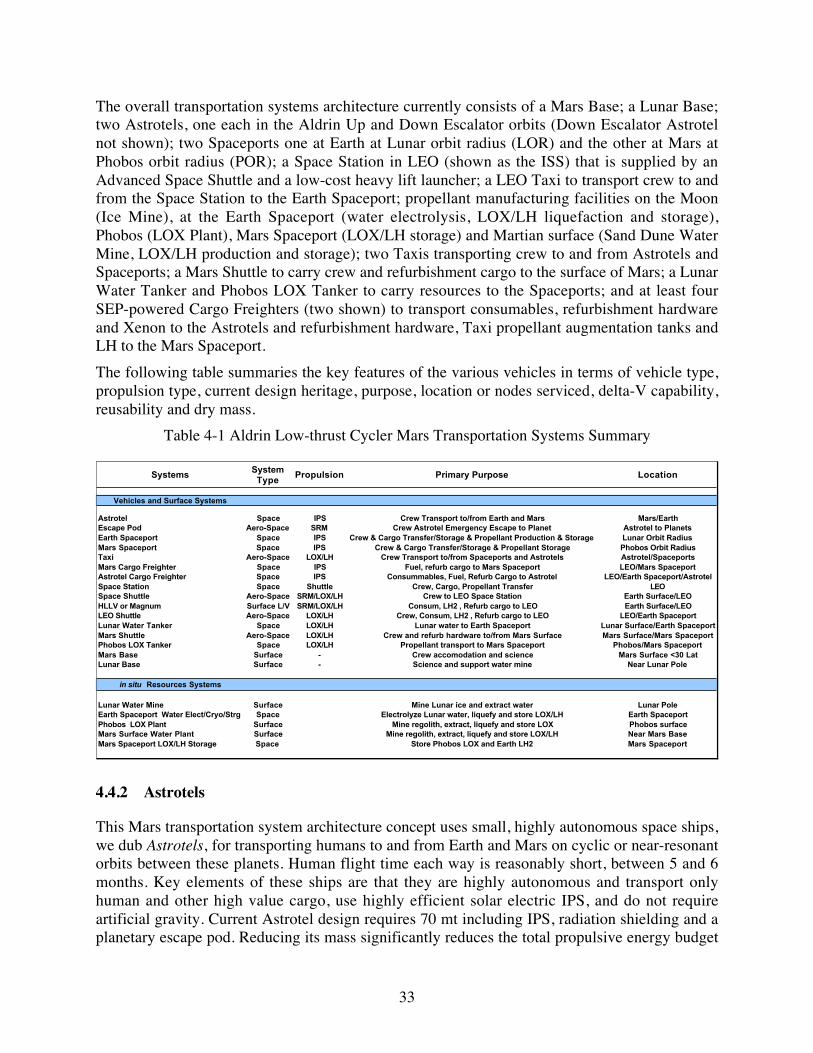
33
The overall transportation systems architecture currently consists of a Mars Base; a Lunar Base;two Astrotels, one each in the Aldrin Up and Down Escalator orbits (Down Escalator Astrotelnot shown); two Spaceports one at Earth at Lunar orbit radius (LOR) and the other at Mars atPhobos orbit radius (POR); a Space Station in LEO (shown as the ISS) that is supplied by anAdvanced Space Shuttle and a low-cost heavy lift launcher; a LEO Taxi to transport crew to andfrom the Space Station to the Earth Spaceport; propellant manufacturing facilities on the Moon(Ice Mine), at the Earth Spaceport (water electrolysis, LOX/LH liquefaction and storage),Phobos (LOX Plant), Mars Spaceport (LOX/LH storage) and Martian surface (Sand Dune WaterMine, LOX/LH production and storage); two Taxis transporting crew to and from Astrotels andSpaceports; a Mars Shuttle to carry crew and refurbishment cargo to the surface of Mars; a LunarWater Tanker and Phobos LOX Tanker to carry resources to the Spaceports; and at least fourSEP-powered Cargo Freighters (two shown) to transport consumables, refurbishment hardwareand Xenon to the Astrotels and refurbishment hardware, Taxi propellant augmentation tanks andLH to the Mars Spaceport.
The following table summaries the key features of the various vehicles in terms of vehicle type,propulsion type, current design heritage, purpose, location or nodes serviced, delta-V capability,reusability and dry mass.
Table 4-1 Aldrin Low-thrust Cycler Mars Transportation Systems Summary
Systems System Type
Propulsion Primary Purpose Location
Vehicles and Surface Systems
Astrotel Space IPS Crew Transport to/from Earth and Mars Mars/EarthEscape Pod Aero-Space SRM Crew Astrotel Emergency Escape to Planet Astrotel to PlanetsEarth Spaceport Space IPS Crew & Cargo Transfer/Storage & Propellant Production & Storage Lunar Orbit RadiusMars Spaceport Space IPS Crew & Cargo Transfer/Storage & Propellant Storage Phobos Orbit RadiusTaxi Aero-Space LOX/LH Crew Transport to/from Spaceports and Astrotels Astrotel/SpaceportsMars Cargo Freighter Space IPS Fuel, refurb cargo to Mars Spaceport LEO/Mars SpaceportAstrotel Cargo Freighter Space IPS Consummables, Fuel, Refurb Cargo to Astrotel LEO/Earth Spaceport/AstrotelSpace Station Space Shuttle Crew, Cargo, Propellant Transfer LEOSpace Shuttle Aero-Space SRM/LOX/LH Crew to LEO Space Station Earth Surface/LEOHLLV or Magnum Surface L/V SRM/LOX/LH Consum, LH2 , Refurb cargo to LEO Earth Surface/LEOLEO Shuttle Aero-Space LOX/LH Crew, Consum, LH2 , Refurb cargo to LEO LEO/Earth SpaceportLunar Water Tanker Space LOX/LH Lunar water to Earth Spaceport Lunar Surface/Earth SpaceportMars Shuttle Aero-Space LOX/LH Crew and refurb hardware to/from Mars Surface Mars Surface/Mars SpaceportPhobos LOX Tanker Space LOX/LH Propellant transport to Mars Spaceport Phobos/Mars SpaceportMars Base Surface - Crew accomodation and science Mars Surface <30 LatLunar Base Surface - Science and support water mine Near Lunar Pole
in situ Resources Systems
Lunar Water Mine Surface Mine Lunar ice and extract water Lunar PoleEarth Spaceport Water Elect/Cryo/Strg Space Electrolyze Lunar water, liquefy and store LOX/LH Earth SpaceportPhobos LOX Plant Surface Mine regolith, extract, liquefy and store LOX Phobos surfaceMars Surface Water Plant Surface Mine regolith, extract, liquefy and store LOX/LH Near Mars BaseMars Spaceport LOX/LH Storage Space Store Phobos LOX and Earth LH2 Mars Spaceport
4.4.2 Astrotels
This Mars transportation system architecture concept uses small, highly autonomous space ships,we dub Astrotels, for transporting humans to and from Earth and Mars on cyclic or near-resonantorbits between these planets. Human flight time each way is reasonably short, between 5 and 6months. Key elements of these ships are that they are highly autonomous and transport onlyhuman and other high value cargo, use highly efficient solar electric IPS, and do not requireartificial gravity. Current Astrotel design requires 70 mt including IPS, radiation shielding and aplanetary escape pod. Reducing its mass significantly reduces the total propulsive energy budget

34
required for course corrections to the 2,780-kg propellant required for all major corrections over15 years. The IPS consists of eight 50-cm diameter ion engines each requiring 17.2 kW of powerand producing thrust at an Isp of 5000s. Propulsion and crew power is supplied via a 160 kWconcentrator solar array with multi-component, mechanically stacked solar cells. The 70 mt massincludes a habitability module for a crew of ten. The size and volume of this system provides acrew volume of about 6 times that available to today’s Space Shuttle crew. The astronaut livingspace is a three-story structure patterned after the TransHab module that has been under studyby NASA. Figure 1-1 is a schematic of one concept for an Astrotel that is approaching Mars. Thetwo smaller modules between the TransHab and the solar array are cargo bays. The AstrotelCargo Freighter autonomously delivers all cargo to the Astrotel contained within a standardcargo bay. These are pressurized modules to facilitate crew unloading of consumables and RRUhardware. Once emptied the cargo bay could be discarded or used to provide added crewvolume, perhaps for zero-g squash courts and other recreational uses. The entire Astrotelrequires 70 mt of hardware to be delivered to the cyclic orbit in the build up phase and about 60mt of crew consumables, RRU hardware, and IPS propellant every 15 years. A detailed massbreakdown of the Astrotel is provided in Section 8.
4.4.3 Spaceports
Two Spaceports are envisioned, one for Mars and the other located at Earth. Spaceports arecollection points for the arrival and distribution of humans, cargo and propellants destined fortransport to planet or natural satellite surfaces or to cycling Astrotels. In addition because of thenearly 100% availability of solar energy, Spaceports are ideal locations for propellant processing,liquefaction, and cryogenic storage.
Spaceport design and operation are based on Astrotel design heritage. Crew stay times arelimited in order to minimize effects of zero-g. Crew maintenance is minimized by maximumapplication of autonomy in order to shorten stay times. Station-keeping, orbit corrections, orbit-phasing delta-Vs are performed by the same solar powered IPS envisioned for the Astrotels.Spaceport design heritage is based on the design of Astrotels except without the large power andpropulsion subsystems.
4.4.4 Taxis
Taxis provide transportation between Spaceports and Astrotels. In order to minimize propulsiveenergy use, Taxis use advanced aeroassist technologies for planetary orbit capture. Aerocapturetakes maximum advantage of planetary atmospheric drag to slow the vehicle on its approachfrom planetary space. The initial sizing of the Taxi vehicle was carried out during Phase I. Keyassumptions are:
� Minimal radiation protection (equivalent to ~10 cm polyethylene surrounding crew module)for the crew is provided since transfer times to/from the Astrotels could be 7-10 days
� No cargo is transported to the Astrotel by the Taxi except crew
� 10-15% of the entry mass is aeroshell
� LOX/LH propulsion system at Isp of 460 s and thrust of 60,000 lbs./engine
� Fuel cell energy storage, no solar array power source

35
� Propellant tank augmentation (expendable drop tanks and in some cases additional engines)are required at Mars
The nominal Taxi system aeroshell design is an elliptical raked cone (see Phase I Final Report).Taxis utilize LOX/LH propulsion to escape planets and place them and their crew ontohyperbolic rendezvous trajectories with the interplanetary orbiting Astrotels. Figure 4-5 depicts aTaxi departing the Earth Spaceport with the Moon in the background and a Taxi duringaerocapture at Mars arrival. This figure illustrates the crew module, propellant tanks, rocketengines (in their deployed position), and the aeroshell. Propellant capacity of the basic Taxivehicle is 20.6 mt. Rendezvous time to Astrotels would be measured in days in order to reducethe duration of crew time in the expected cramped quarters. Crew volume is comparable to whatthe Apollo astronauts had on their flights to the Moon and back. In the Mars arrival figure theTaxi is viewed from 50 km above Mars during aero-cruise. Note the rocket engines are in theirstowed position in order to minimize altering the air flow. During this time the tanks are almostempty, containing only the propellant necessary to rendezvous with the Mars Spaceport, in aPhobos radius orbit, after aerocapture. The crew module is shown in see-through mode so onecan observe the crew g-seats, which rotate in order to accommodate the different g-load directionduring aerocapture as opposed to g-load direction during propulsive thrust maneuvers.
Figure 4-5 Taxi Leaving the Earth (left) and Aerocapture at Mars (right)
The usable volume of the crew module is roughly comparable to that of the Apollo CommandModule, or about 2-3 m3 per crewmember. The crew module has 10 crew pods, which includes arotating g-seat or hammock, communications and computer panels, and hygiene systems. Atleast two crewmembers have additional Taxi control and monitoring equipment adapted to theirg-seat. Crew hammocks rotate in order to accommodate the varying acceleration vector duringaerocapture maneuvers and very different acceleration vectors during staged propulsive rocketburns. Maximum g-load is nominally 5. The crew module is cylindrical in shape and surroundedby about 3-cm thick polyethylene radiation shield to protect the crew during major solar particleevents. This level of shielding is less than suggested thickness; on the other hand there is nocurrent recommendation. This is an area for further study.
At Mars the departure delta-Vs are significantly larger than at Earth due to the higher V-infinityof the Astrotel Down Escalator orbit as it passes Mars (Phase I Final Report). For these largerdelta-Vs the Taxi escape maneuver must occur in stages at Mars. Two stages are required for 3
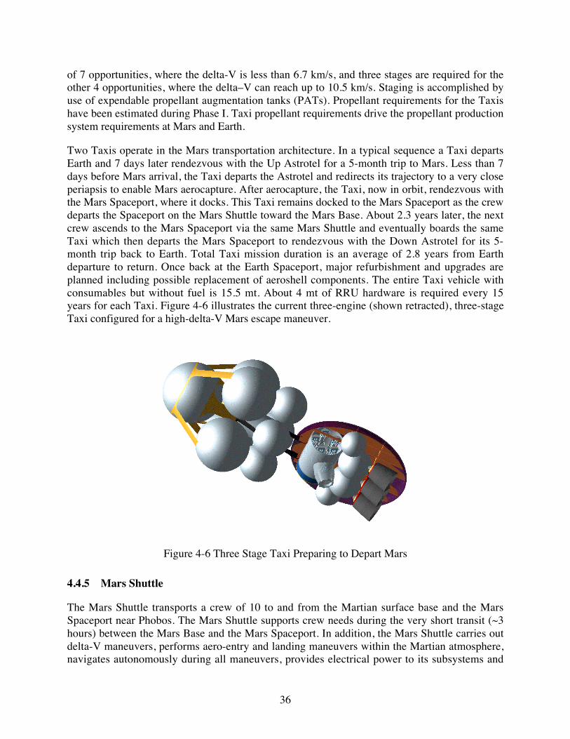
36
of 7 opportunities, where the delta-V is less than 6.7 km/s, and three stages are required for theother 4 opportunities, where the delta–V can reach up to 10.5 km/s. Staging is accomplished byuse of expendable propellant augmentation tanks (PATs). Propellant requirements for the Taxishave been estimated during Phase I. Taxi propellant requirements drive the propellant productionsystem requirements at Mars and Earth.
Two Taxis operate in the Mars transportation architecture. In a typical sequence a Taxi departsEarth and 7 days later rendezvous with the Up Astrotel for a 5-month trip to Mars. Less than 7days before Mars arrival, the Taxi departs the Astrotel and redirects its trajectory to a very closeperiapsis to enable Mars aerocapture. After aerocapture, the Taxi, now in orbit, rendezvous withthe Mars Spaceport, where it docks. This Taxi remains docked to the Mars Spaceport as the crewdeparts the Spaceport on the Mars Shuttle toward the Mars Base. About 2.3 years later, the nextcrew ascends to the Mars Spaceport via the same Mars Shuttle and eventually boards the sameTaxi which then departs the Mars Spaceport to rendezvous with the Down Astrotel for its 5-month trip back to Earth. Total Taxi mission duration is an average of 2.8 years from Earthdeparture to return. Once back at the Earth Spaceport, major refurbishment and upgrades areplanned including possible replacement of aeroshell components. The entire Taxi vehicle withconsumables but without fuel is 15.5 mt. About 4 mt of RRU hardware is required every 15years for each Taxi. Figure 4-6 illustrates the current three-engine (shown retracted), three-stageTaxi configured for a high-delta-V Mars escape maneuver.
Figure 4-6 Three Stage Taxi Preparing to Depart Mars
4.4.5 Mars Shuttle
The Mars Shuttle transports a crew of 10 to and from the Martian surface base and the MarsSpaceport near Phobos. The Mars Shuttle supports crew needs during the very short transit (~3hours) between the Mars Base and the Mars Spaceport. In addition, the Mars Shuttle carries outdelta-V maneuvers, performs aero-entry and landing maneuvers within the Martian atmosphere,navigates autonomously during all maneuvers, provides electrical power to its subsystems and

37
carries RRU cargo from the Mars Spaceport to the Mars Base. The Mars Shuttle is designed totravel only between the Mars surface and the Mars Spaceport at Phobos.
An early Mars Shuttle design version, shown in Figure 4-7, is a low lift/drag (L/D) ratio designwith a deployable 20-m diameter aerobrake deployed before entry and landing. At take-off, theaerobrake is stowed to reduce atmospheric cross-section and minimize drag. The low lift/dragratio design offers reduced mass, ease of fabrication, reduced cost and growth accommodationover higher L/D designs. Though the vehicle is sized for carrying up to 10 mt of cargo to theMars Base, the Mars surface cargo requirement is only about 7.8 mt, thus indicating considerablereserve exists in the design.
Figure 4-7 Mars Shuttle Launching from Surface (Left) and at Mars Entry (Right)
4.4.6 Lunar Water Tanker
The Lunar Water Tanker (LWT) is a reusable vehicle that can be fueled either on the Moon or atthe Earth Spaceport. It transports water from the lunar surface to the Earth Spaceport where itrefuels and then returns empty to the lunar surface. The LWT is not crewed thus minimizingadditional infrastructure. The key power and LOX/LH propulsion elements are in common withother elements of the Mars transportation architecture in order to minimize development andrecurring cost. The maximum payload of the LWT is expected to be about 19 mt of lunar water.Leaving the Moon for the fuel depot somewhere at lunar orbit radius, the required delta-V is2200 m/s, which requires a propellant load of about 16 mt of LOX/LH. The departure delta-Vpropellant is assumed to be produced totally on the Moon. Once delivered to L-1, some of thewater is processed into LOX/LH for the LWT to return to the Moon. Since the LWT is emptyleaving lunar orbit radius, only about 5 mt of LOX/LH propellants (processed Lunar water) arerequired to return to the Moon. The net materials left at the fuel depot at lunar orbit radius isabout 8 mt of LOX/LH for use as propellants and some excess oxygen. Total water produced atthe Moon is 37 mt every 2 1/7 year cycle.
4.4.7 Integrated Propellant and Cargo Use Profiles
In this section we summarize the overall propellant and cargo masses that move through nodes ofthe transportation architecture over a 15-year period. Vehicle propellant, crew consumable andRRU mass requirements over 15 years have been summarized and collected in MAMA at theireventual transportation node in the following tables. All masses are kilograms.

38
Table 4-2 Cargo Mass Summary
Location-------------> At LEO At Earth Spaceport
At Mars Spaceport
At Surface of Mars
At Surface of Moon
At Astrotels (2 vehicles)
Users
Taxis (2)Propellant
LOX 102,935 619,612LH 14,705 88,516Tot 117,641 708,128
Water required at Spaceport 132,346
Augmentation Tanks 88,047 88,047
Taxi Refurb Mass 23,258 23,258
LEO Shuttle (1)
Refurb Mass 23,258
Mars Shuttle (1)Propellant
LOX 83,326 229,868 LH 11,904 32,838
Total 95,230 262,706
Water required on Mars 295,544
Refurb Mass 5,444 5,444
Lunar Polar Base
Polar Ice Mine Refurb Mass 1,091 1,091 1091
Mars Base
Base Refurb Mass 50,942 50,942 50,942 Propellant Plant Refurb Mass 3,705 3,705 3,705
Phobos LOX Plant
Propellant Plant Refurb Mass 3,237 3,237
Astrotels (2)Crew Consumables 100,324 100,324
Xenon Propellant 5,560 5,560 Refurb Mass 14,690 14,690
Mars Spaceport (1)Refurb Mass 14,690 14,690
Phobos LOX Storage Refurb Mass 257 257Station-keeping Xenon propellant Mass
Earth Spaceport (1)Refurb Mass 14,690
LOX/LH Production Plant Refurb mass 80 80Station-keeping Xenon propellant Mass
Lunar Water Tanker (1)Refurb Mass
Astrotel Cargo Freighter
Xenon Propellant 55,497 Refurb Mass 2,291
Mars Cargo Freighter
Xenon Propellant 138,958 Refurb Mass 5,299

39
These cargo use profiles have been summarized as to where the cargo are needed throughout thetransportation architecture for the 15 years of operation and displayed in the following table (allmasses are in kg).
Table 4-3 Total Cargo Requirements
Location-------------> At LEO At Earth Spaceport
At Mars Spaceport
At Surface of Mars
At Surface of Moon
At Astrotels (2 vehicles)
Total Cargo Requirements
LOX 1 0 2 , 9 3 5 7 0 2 , 9 3 8 2 2 9 , 8 6 8L H 1 4 , 7 0 5 1 0 0 , 4 2 0 3 2 , 8 3 8
Water 1 3 2 , 3 4 6 2 9 5 , 5 4 4Xenon 2 0 0 , 0 1 6 5 , 5 6 0
Refurb Mass 1 4 8 , 2 4 4 3 9 , 1 2 0 7 8 , 2 7 6 5 4 , 6 4 7 1 , 0 9 1 1 4 , 6 9 0Augmentation Tanks 8 8 , 0 4 7 8 8 , 0 4 7
Crew Consumables 1 0 0 , 3 2 4 1 0 0 , 3 2 4 Communications Satellites
Total Mass Required 5 3 6 , 6 3 0 2 8 9 , 1 0 6 9 6 9 , 6 8 0 6 1 2 , 8 9 7 1 , 0 9 1 1 2 0 , 5 7 4
Finally, this cargo has been divided into the various delivery systems, which is displayed in thenext chart. These propellant and cargo use profiles provide the derived requirements for thetransport of cargo and propellant throughout the architecture and the requirements on the ISRUproduction rates.
Table 4-4 Cargo Delivery System Manifest
Location-------------> At LEO At Earth Spaceport
At Mars Spaceport
At Surface of Mars
At Surface of Moon
At Astrotels (2 vehicles)
Delivery Systems
SEP Freighter Delivered Cargo 3 9 , 1 2 0 2 6 6 , 7 4 2 1 2 0 , 5 7 4
Cargo Freighter Each Trip 5,589 38,106 17,225
Lunar Water Tanker Total 1 3 2 , 3 4 6 1 , 0 9 1Number of Trips 7
Lunar Water Tanker Each Trip 18,907 156
Phobos LOX Tanker Total 7 0 2 , 9 3 8Number of Trips 3 0
Phobos LOX Tanker Each Trip 23,431
Mars Shuttle 5 4 , 6 4 7Number of Trips 7
Mars Shuttle Each Trip 7,807
4.4.8 Cargo Freighters
Two types of cargo transporters are planned, an Astrotel Cargo Freighter and a Mars CargoFreighter. These vehicles deliver cargo from LEO to Astrotels and Spaceports. See Section 4.4.7for the integrated cargo requirements. Cargo Freighters use xenon ion propulsion systems tospiral out of Earth orbit, shape the interplanetary trajectory to rendezvous with Astrotels or spiralinto Mars orbit to Phobos. The Astrotel Cargo Freighter delivers a standard pressurized cargobay module to the Astrotel. The cargo bay approach facilitates crew unloading.

40
The Freighter solar arrays consist of multiple sets of identical Astrotel solar arrays (80 kWpanels). The propulsion system shares high degree of technology heritage with the Astrotel IPS.The following charts describe the design parameters for these important vehicle systems, whichwill be a subject of more design during Phase II.
Table 4-5 Astrotel Cargo Freighter Sizing
Mass of Cargo each trip to Astrotel 17,225 kgInitial mass of Cargo Freighter in LEO 28,632 kg
Propellant Mass 7,928 kgFinal Mass of Freighter 3,479 kg
Po 286.3 kWPower/Propulsion Mass (Mps) 2291 kg
Table 4-6 Mars Cargo Freighter Sizing
Mass of Cargo each trip to Mars Spaceport 38,106 kgInitial mass of Cargo Freighter in LEO 66,237 kg
Propellant Mass 19,851 kgFinal Mass of Freighter 8,280 kg
Po 662.4 kWPower/Propulsion Mass (Mps) 5,299 kg
4.4.9 In Situ Resource Utilization Systems
The following sections summarize the in situ resource systems for the Moon, the EarthSpaceport, Mars surface, Phobos and the Mars Spaceport. Displayed below are the solar poweroption. Duty cycles for all surface systems are assumed to be near 100% for the nuclear options.
4.4.9.1 Lunar Ice Mine
The automated Lunar Ice Mine is assumed to operate only during periods of sufficient solarillumination on its surface solar array, thus 34% of the time. During the night batteries or non-regenerative fuel cells provide keep-alive power. Ice is mined and melted into water and thentransported to the Earth Spaceport for production of LOX/LH propellants.
Table 4-7 Lunar Ice Mine Mass and Power
Resource System Element PurposeRate,
kg/hr or Mass, kg
UnitsDuty
Cycle, %
Mass Factor, kg per rate or per stored
kg
Total Mass,
kg
Specific Power, kW
per kg/hr produced
Total Power,
kW
Total Water Required 37,040 kgMining and Excavation (0.16-g) Mine regolith (kg/hr) 1235 kg/hr 34% 0.20 247 0.0133 16.46Soil Hauler (0.16-g) Haul soil to reactor and slag awayReactor/Condensor Heats soil from -200oC to 50°C (kg H2O/hr) 12.35 kg/hr 34% 100.00 1,235 17 209.89Water Storage Stores extracted water (.33 x annual water production) 12.35 kg/hr 100% 0.02 247Distribution Distributes liquids and gases to where they are processed 12.35 16.00 198Electrolyzer Produces propellant for launching water to L1 (kg/hr) 5.37 kg/hr 34% 20.00 107 6.5 34.92LH liquefaction Provides LH for transfer vehicle (kg H2/hr) 0.67 kg/hr 34% 16.50 11 20 13.43Lox liquefaction Provides Lox for transfer vehicle (kg O2/hr) 4.70 kg/hr 34% 6.50 31 0.5 2.35Lox, LH storage Assumes immediate transfer to L1 Total Power--> 277.06Solar Array - XX kW Produces electrical power during Lunar day (kW) 34% 4.00 1,108Power Mgmt & Dist Power voltage/freq control and distribution 111
Total mass----> 3,294

41
4.4.9.2 Earth Spaceport LOX/LH Production and Depot
The Earth Spaceport is an ideal location for the electrolysis of lunar water into oxygen andhydrogen, liquefaction into LOX/LH and finally storage of these propellants. Nearly continuouspower is available using high efficiency solar arrays. The Earth Spaceport ISRU facility isexpected to operate at a 90% duty cycle.
Table 4-8 Earth Spaceport LOX/LH Production and Depot Mass and Power
Resource System Element PurposeRate,
kg/hr or Mass, kg
UnitsDuty
Cycle, %
Mass Factor, kg per rate or per stored
kg
Total Mass,
kg
Specific Power, kW per kg/hr produced
Total Power,
kW
Water Delivered to L1 18,907 kgWater Storage Stores Lunar water after delivery to L1 (3 mo. supply) 4,727 kg 100% 0.01 47Electrolysis Reactor Converts water to oxygen and hydrogen (kg/hr) 1.97 kg/hr 91% 20.00 36 6.5 12.8Distribution Distributes liquids and gases to where they are processed 50 kg 91% 1.00 46LH liquefaction Liquefies H2 0.22 kg/hr 91% 16.50 3 20 4.4LoX liquefaction Liquefies Ox 1.75 kg/hr 91% 6.50 10 0.5 0.9LH Storage H2 gas storage at X°C (kg) - 3 mo. supply, rest in Taxi 480 kg 100% 0.15 72 0.0016 0.8LOx Storage Cryogenic gas storage at -183oC - 3 mo. supply, rest in Taxi 3837 kg 100% 0.07 269 0.001 3.8
Total Power--> 22.7Solar Array - XX kW Produces electrical power 100% of time (kW) 100% 4.00 91Power Mgmt & Dist Power voltage/freq control and distribution 9
Total Mass---> 583
4.4.9.3 Mars Dune Water Mine
Water is recovered from the regolith of Mars. Dune fields could be an excellent location for anexcavation site. Once water is recovered from the soil it is electrolyzed into oxygen andhydrogen, liquefied into LOX/LH and finally stored within the Mars Shuttle tanks. The operationon Mars is fully automatic and operates at a 34% duty cycle along with the normal day/nightperiods.
Table 4-9 Mars Dune Water Mine Mass and Power
Resource System Element PurposeRate,
kg/hr or Mass, kg
UnitsDuty
Cycle, %
Mass Factor, kg per rate or per stored
kg
Total Mass,
kg
Specific Power, kW
per kg/hr produced
Total Power,
kW
Total Water Required 19,703 kg/yrDune Collection (0.38-g) Excavates likely water bearing soil (kg/hr) 657 kg/hr 34% 0.27 177 0.00991 6.5Soil Hauler (0.38-g) Transports soil to reactor and slag awayReactor/Condensor Heats soil to 500°C to remove water (kg/hr) 6.57 kg/hr 34% 205 1,346 35 229.9Water Storage Stores water before electrolysis (kg) 1147 kg 100% 0.04 46Electrolysis Reactor Converts water to oxygen and hydrogen (kg/hr) 6.57 kg/hr 34% 20.00 131 6.5 42.7Distribution Distributes liquids and gases to where they are processed 6.57 kg/hr 3.70 24LH Liquifaction Liquifies hydrogen (kg/hr) 0.82 kg/hr 34% 16.50 14 20 16.4LOX Liquifaction Liquifies oxygen (kg/hr) 5.75 kg/hr 34% 6.65 38 0.5 2.9LOX Storage Crygenic gas storage at -183°C (25% of annual production, res 5517 kg 100% 0.07 386 0.5 1.15LH Storage Crygenic gas storage at Y°C (25% of annual production, rest o 788 kg 100% 0.15 118 20.0 6.57
Total Power--> 306.1Solar Array Produces electrical power 33% of time 34% 9.24 2,829Power Mgmt & Dist Power voltage/freq control and distribution 141
Total Mass---> 5,251
4.4.9.4 Phobos LOX Plant
Phobos regolith is excavated and processed to recover oxygen. The oxygen is then liquefied andtransported to the Mars Spaceport where it can be stored in Taxi propellant tanks or propellantaugmentation tanks (PATs). The plant on Phobos is fully automatic and operates at a 34% dutycycle consistent with the day/night periods.

42
Table 4-10 Phobos LOX Plant Mass and Power
Resource System Element PurposeRate,
kg/hr or Mass, kg
UnitsDuty
Cycle, %
Mass Factor, kg per rate or per stored
kg
Total Mass,
kg
Specific Power, kW
per kg/hr produced
Total Power,
kW
Total Oxygen Required kg/yr 46,863 kg/yrExcavation (zero-g) Excavates Phobos regolith (kg/yr) 137,831 kg/yrExcavation (zero-g) Excavates Phobos regolith (kg/hr) 45.9 kg/hr 34% 1.00 46 0.06 2.8Soil Hauler (zero-g) Transports soil to reactor and slag awayCarbothermal Reactor Reactions at 1600 °C to generate oxygen (kgO2/hr) 15.73 kg/hr 34% 96.00 1,510 16 251.7Distribution Distributes oxygen to where it is liquified 50 kg 1.00 50Liquifaction Liquifies oxygen (kg/hr) 15.73 kg/hr 34% 6.50 102 0.5 7.9LOX Storage Assumes immediate transfer to Marsport
Total Power--> 262.4Solar Array - XX kW Produces electrical power 33% of time (kW) 34% 9.24 2,425Power Mgmt & Dist Power voltage/freq control and distribution 121
Total Mass---> 4,255
4.4.9.5 Mars Spaceport Propellant Depot
Phobos LOX and Earth LH are stored at the Mars Spaceport, in Taxi PATs and Mars Shuttletanks. The operation at the Mars Spaceport is nearly continuous, except for occasional eclipses ofthe Sun by Mars.
Table 4-11 Mars Spaceport Propellant Depot Mass and Power
Resource System Element PurposeRate,
kg/hr or Mass, kg
UnitsDuty
Cycle, %
Mass Factor, kg per rate or per stored
kg
Total Mass,
kg
Specific Power, kW
per kg/hr produced
Total Power,
kW
Phobos LOX Storage* Crygenic gas storage at -183oC - (25% ann. prod., rest in Taxi tanks) 11,716 kg 100% 0.07 820 0.00018 2.1Earth LH Storage* Crygenic Earth LH storage at Y°C - (25% ann. Req't, rest in Taxi tanks) 1,674 kg 100% 0.15 251 0.0084 14.1
Total Power--> 16.2Solar Array - XX kW at ~1.5 AU Produces electrical power 100% of time 9.24 149Power Mgmt & Dist Power voltage/freq control and distribution 7
Total Mass---> 1,228
4.5 Stopover Cycler Architecture
This section describes the Stopover Cycler architecture.
4.5.1 Overview
The Stopover Cycler architecture uses the Stopover Cycler orbits for transport between Earth andMars. These orbits are direct transfers with stops at both planets. Stopover Cycler orbits arefurther described in Sections 4.3 and 5.3.2. Flight duration is limited to 6 months or 180 days,although for the maximum propellant loading the trips could be considerable shorter for someopportunities. In this architecture the Interplanetary Taxi and planetary Spaceports areeliminated because the Astrotel itself is captured into a lunar orbit radius upon arriving at Earthor Phobos orbit radius upon arriving at Mars. Once in these transportation node orbits theAstrotel provides all the services to crews that the Spaceport provides in the Aldrin Low-thrustarchitecture. Propellant depots will be still be situated in these nodes in order to providepropellant processing and storage facilities. Because there are no continuous cycling Astrotels,the requirement for their remote resupply is eliminated along with the Astrotel Cargo Freighter.Since there is still a requirement to transport materiel to Mars, the Mars Cargo Freighter is still inoperation. Chemical (LOX/LH) propulsion systems are assumed for the Astrotel orbit capture

43
since high thrust maneuvers are required in order to keep flight duration low. Nominally thesepropellants are produced at ISRU sites in a similar fashion to the Aldrin Low-thrust architecture,except that considerably more propellants must be generated.
4.5.2 Integrated Propellant and Cargo Use Profiles
In this section we summarize the overall propellant and cargo masses that move through nodes ofthe Stopover Cycler transportation architecture over a 15-year period. Vehicle propellant, crewconsumables and RRU mass requirements over 15 years have been summarized and collected inMAMA at their eventual transportation node in the following tables. All masses are kilograms.
Table 4-12 Cargo Mass Summary for Stopover Architecture
Location-------------> At LEO At Earth Depot
At Mars Depot At Surface of Mars
At Surface of Moon
At Astrotels (2 vehicles)
Users
Mars Shuttle (1)Propellant
LOX 83,428 230,306 LH 11,918 11,918 32,901
Total 95,346 263,207
Water required on Mars 296,108
Refurb Mass 4,403 4,403
Lunar Polar Base
Polar Ice Mine Refurb Mass 1,724 1,724 1724
Mars Base
Base Refurb Mass 50,942 50,942 50,942 Propellant Plant Refurb Mass 3,712 3,712 3,712
Phobos LOX Plant
Propellant Plant Refurb Mass 6,449 6,449
Astrotels (2)LOX 1,084,319 1,316,883
LH 180,720 219,480Crew Consumables 112,084 56,042 56,042
Xenon Propellant - - Refurb Mass 74,640 37,320 37,320
Mars Fuel DepotRefurb Mass
Phobos LOX Storage Refurb Mass 561 561Station-keeping Xenon propellant Mass
Earth Fuel DepotRefurb Mass
LOX/LH Production Plant Refurb mass 104 104Station-keeping Xenon propellant Mass
Lunar Water Tanker (1)Refurb Mass
Astrotel Cargo Freighter
Xenon Propellant - Refurb Mass -
Mars Cargo Freighter
Xenon Propellant 903,891 Refurb Mass 34,468
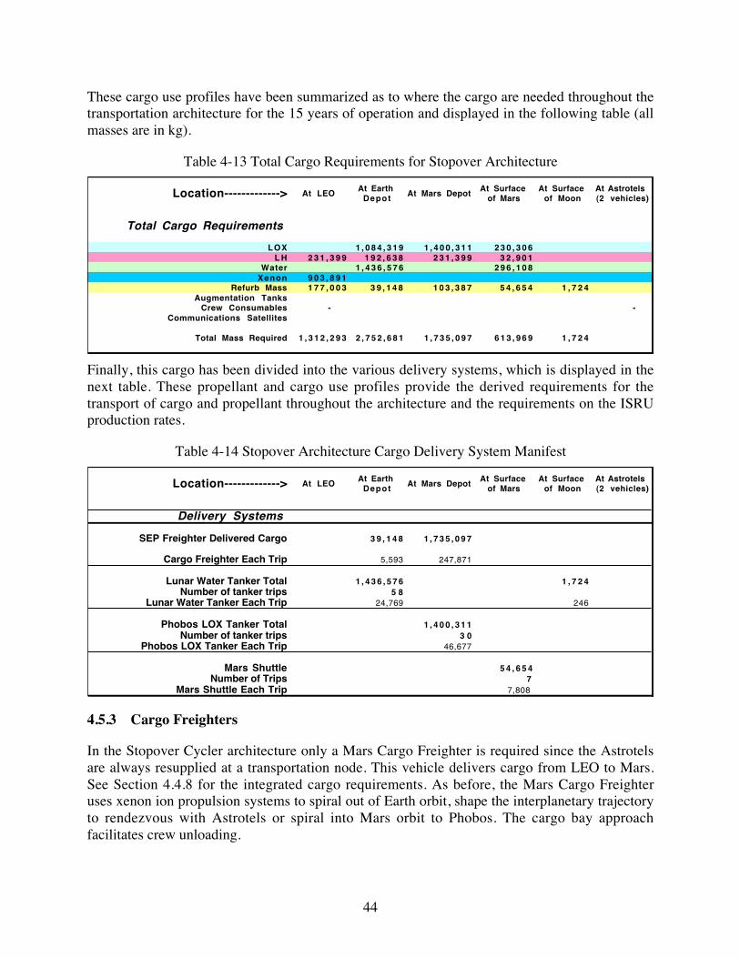
44
These cargo use profiles have been summarized as to where the cargo are needed throughout thetransportation architecture for the 15 years of operation and displayed in the following table (allmasses are in kg).
Table 4-13 Total Cargo Requirements for Stopover Architecture
Location-------------> At LEO At Earth Depot At Mars Depot At Surface
of MarsAt Surface
of MoonAt Astrotels (2 vehicles)
Total Cargo Requirements
LOX 1 , 0 8 4 , 3 1 9 1 , 4 0 0 , 3 1 1 2 3 0 , 3 0 6L H 2 3 1 , 3 9 9 1 9 2 , 6 3 8 2 3 1 , 3 9 9 3 2 , 9 0 1
Water 1 , 4 3 6 , 5 7 6 2 9 6 , 1 0 8Xenon 9 0 3 , 8 9 1
Refurb Mass 1 7 7 , 0 0 3 3 9 , 1 4 8 1 0 3 , 3 8 7 5 4 , 6 5 4 1 , 7 2 4Augmentation Tanks
Crew Consumables - - Communications Satellites
Total Mass Required 1 , 3 1 2 , 2 9 3 2 , 7 5 2 , 6 8 1 1 , 7 3 5 , 0 9 7 6 1 3 , 9 6 9 1 , 7 2 4
Finally, this cargo has been divided into the various delivery systems, which is displayed in thenext table. These propellant and cargo use profiles provide the derived requirements for thetransport of cargo and propellant throughout the architecture and the requirements on the ISRUproduction rates.
Table 4-14 Stopover Architecture Cargo Delivery System Manifest
Location-------------> At LEO At Earth Depot At Mars Depot At Surface
of MarsAt Surface
of MoonAt Astrotels (2 vehicles)
Delivery Systems
SEP Freighter Delivered Cargo 3 9 , 1 4 8 1 , 7 3 5 , 0 9 7
Cargo Freighter Each Trip 5,593 247,871
Lunar Water Tanker Total 1 , 4 3 6 , 5 7 6 1 , 7 2 4Number of tanker trips 5 8
Lunar Water Tanker Each Trip 24,769 246
Phobos LOX Tanker Total 1 , 4 0 0 , 3 1 1Number of tanker trips 3 0
Phobos LOX Tanker Each Trip 46,677
Mars Shuttle 5 4 , 6 5 4Number of Trips 7
Mars Shuttle Each Trip 7,808
4.5.3 Cargo Freighters
In the Stopover Cycler architecture only a Mars Cargo Freighter is required since the Astrotelsare always resupplied at a transportation node. This vehicle delivers cargo from LEO to Mars.See Section 4.4.8 for the integrated cargo requirements. As before, the Mars Cargo Freighteruses xenon ion propulsion systems to spiral out of Earth orbit, shape the interplanetary trajectoryto rendezvous with Astrotels or spiral into Mars orbit to Phobos. The cargo bay approachfacilitates crew unloading.

45
The propulsion system of the Mars Cargo Freighter shares a high degree of technology heritagewith the Astrotel IPS although the power level is considerably more.
Table 4-15 Stopover Mars Cargo Freighter Sizing
Mass of Cargo each trip to Mars Spaceport 247,871 kgInitial mass of Cargo Freighter in LEO 430,855 kg
Propellant Mass 129,127 kgFinal Mass of Freighter 53,857 kg
Po 4,308.6 kWPower/Propulsion Mass (Mps) 34,468 kg
4.5.4 In Situ Resource Utilization Systems
The following sections summarize the in situ resource systems for the Moon, the EarthPropellant Depot, Mars surface, Phobos and the Mars Propellant Depot for the StopoverArchitecture. The In situ Resource Utilization Systems (ISRU) are identical to the Aldrin Low-thrust Cycler architecture however they are scaled for the different propellant productionrequirements of the Stopover architecture. Displayed below are the solar power options. As withthe Aldrin Low-thrust architecture, duty cycles for surface systems are assumed to be near 100%for the nuclear options.
4.5.4.1 Lunar Ice Mine
The automated Lunar Ice Mine
Table 4-16 Stopover Lunar Ice Mine Mass and Power
Resource System Element Purpose
Rate, kg/hr or Mass,
kg
UnitsDuty
Cycle, %
Mass Factor, kg per rate or per stored
kg
Total Mass,
kg
Specific Power, kW per kg/hr produced
Total Power,
kW
Total Water Required 46,863 kgMining and Excavation (0.16-g) Mine regolith (kg/hr) 1562 kg/hr 34% 0.20 312 0.0133 20.83Soil Hauler (0.16-g) Haul soil to reactor and slag awayReactor/Condensor Heats soil from -200oC to 50°C (kg H2O/hr) 15.62 kg/hr 34% 100.00 1,562 17 265.56Water Storage Stores extracted water (.33 x annual water production) 15.62 kg/hr 100% 0.02 312Distribution Distributes liquids and gases to where they are processed 15.62 16.00 250Electrolyzer Produces propellant for launching water to L1 (kg/hr) 25.31 kg/hr 34% 20.00 506 6.5 164.53LH liquefaction Provides LH for transfer vehicle (kg H2/hr) 3.16 kg/hr 34% 16.50 52 20 63.28Lox liquefaction Provides Lox for transfer vehicle (kg O2/hr) 22.15 kg/hr 34% 6.50 144 0.5 11.07Lox, LH storage Assumes immediate transfer to L1 Total Power--> 525.28Solar Array - XX kW Produces electrical power during Lunar day (kW) 34% 4.00 2,101Power Mgmt & Dist Power voltage/freq control and distribution 210
Total Mass-----> 5,451
4.5.4.2 Earth LOX/LH Propellant Production and Storage Depot
The Lunar Orbit radius is an ideal location for the propellant depot where lunar water iselectrolyzed into oxygen and hydrogen, LOX/LH is liquefied and finally these propellants arestored. Nearly continuous power is available using high efficiency solar arrays. The EarthSpaceport ISRU facility is expected to operate at a 90% duty cycle.

46
Table 4-17 Stopover Earth LOX/LH Production and Depot Mass and Power
Resource System Element Purpose
Rate, kg/hr or Mass,
kg
UnitsDuty
Cycle, %
Mass Factor, kg per rate or per stored
kg
Total Mass,
kg
Specific Power, kW
per kg/hr produced
Total Power,
kW
Water Delivered to L1 24,769 kgWater Storage Stores Lunar water after delivery to L1 (3 mo. supply) 6,192 kg 100% 0.01 62Electrolysis Reactor Converts water to oxygen and hydrogen (kg/hr) 2.58 kg/hr 91% 20.00 47 6.5 16.8Distribution Distributes liquids and gases to where they are processed 50 kg 91% 1.00 46LH liquefaction Liquefies H2 0.29 kg/hr 91% 16.50 4 20 5.7LoX liquefaction Liquefies Ox 2.30 kg/hr 91% 6.50 14 0.5 1.1LH Storage H2 gas storage at X°C (kg) - 3 mo. supply, rest in Taxi 628 kg 100% 0.15 94 0.0016 1.0LOx Storage Cryogenic gas storage at -183oC - 3 mo. supply, rest in Taxi 5027 kg 100% 0.07 352 0.001 5.0
Total Power--> 29.7Solar Array - XX kW Produces electrical power 100% of time (kW) 100% 4.00 119Power Mgmt & Dist Power voltage/freq control and distribution 12
Total Mass---> 749
4.5.4.3 Mars Dune Water Mine
Water is recovered from the regolith of Mars. Dune fields could be an excellent location for anexcavation site. Once water is recovered from the soil it is electrolyzed into oxygen andhydrogen, liquefied into LOX/LH and finally stored within the Mars Shuttle tanks. The operationon Mars is fully automatic and operates at a 34% duty cycle along with the normal day/nightperiods.
Table 4-18 Stopover Dune Water Mine Mass and Power
Resource System Element Purpose
Rate, kg/hr or Mass,
kg
UnitsDuty
Cycle, %
Mass Factor, kg per rate or per stored
kg
Total Mass,
kg
Specific Power, kW
per kg/hr produced
Total Power,
kW
Total Water Required 19,741 kg/yrDune Collection (0.38-g) Excavates likely water bearing soil (kg/hr) 658 kg/hr 34% 0.27 178 0.00991 6.5Soil Hauler (0.38-g) Transports soil to reactor and slag awayReactor/Condensor Heats soil to 500°C to remove water (kg/hr) 6.58 kg/hr 34% 205 1,349 35 230.3Water Storage Stores water before electrolysis (kg) 1147 kg 100% 0.04 46Electrolysis Reactor Converts water to oxygen and hydrogen (kg/hr) 6.58 kg/hr 34% 20.00 132 6.5 42.8Distribution Distributes liquids and gases to where they are processed 6.58 kg/hr 3.70 24LH Liquifaction Liquifies hydrogen (kg/hr) 0.82 kg/hr 34% 16.50 14 20 16.5LOX Liquifaction Liquifies oxygen (kg/hr) 5.76 kg/hr 34% 6.65 38 0.5 2.9LOX Storage Crygenic gas storage at -183°C (25% of annual production, rest on Mars Shuttle) 5527 kg 100% 0.07 387 0.5 1.15LH Storage Crygenic gas storage at Y°C (25% of annual production, rest on Mars Shuttle) 790 kg 100% 0.15 118 20.0 6.58
Total Power--> 306.7Solar Array Produces electrical power 33% of time 34% 9.24 2,834Power Mgmt & Dist Power voltage/freq control and distribution 142
Total Mass---> 5,261
4.5.4.4 Phobos LOX Plant
Phobos regolith is excavated and processed to recover oxygen. The oxygen is then liquefied andtransported to the Mars Propellant Depot where it can be stored in Taxi propellant tanks orpropellant augmentation tanks (PATs). The plant on Phobos is fully automatic and operates at a34% duty cycle consistent with the day/night periods.
Table 4-19 Stopover Phobos LOX Plant Mass and Power
Resource System Element PurposeRate,
kg/hr or Mass, kg
UnitsDuty
Cycle, %
Mass Factor, kg per rate or per stored
kg
Total Mass,
kg
Specific Power, kW
per kg/hr produced
Total Power,
kW
Total Oxygen Required kg/yr 93,354 kg/yrExcavation (zero-g) Excavates Phobos regolith (kg/yr) 274,571 kg/yrExcavation (zero-g) Excavates Phobos regolith (kg/hr) 91.5 kg/hr 34% 1.00 92 0.06 5.5Soil Hauler (zero-g) Transports soil to reactor and slag awayCarbothermal Reactor Reactions at 1600 °C to generate oxygen (kgO2/hr) 31.34 kg/hr 34% 96.00 3,009 16 501.5Distribution Distributes oxygen to where it is liquified 50.00 kg 1.00 50Liquifaction Liquifies oxygen (kg/hr) 31.34 kg/hr 34% 6.50 204 0.5 15.7LOX Storage Assumes immediate transfer to Marsport
Total Power--> 522.7Solar Array - XX kW Produces electrical power 33% of time (kW) 34% 9.24 4,831Power Mgmt & Dist Power voltage/freq control and distribution 242
Total Mass---> 8,427

47
4.5.4.5 Mars Propellant Depot
Phobos LOX and Earth LH are stored at the Mars Propellant Depot that is located near Phobos ina Phobos radius orbit, in Taxi PATs and Mars Shuttle tanks. The operation at the Mars Spaceportis nearly continuous, except for occasional eclipses of the Sun by Mars.
Table 4-20 Stopover Mars Propellant Depot Mass and Power
Resource System Element PurposeRate,
kg/hr or Mass, kg
UnitsDuty
Cycle, %
Mass Factor, kg per rate or per stored
kg
Total Mass,
kg
Specific Power, kW
per kg/hr produced
Total Power,
kW
Phobos LOX Storage* Crygenic gas storage at -183oC - (25% ann. prod., rest in Taxi tanks) 23,339 kg 100% 0.07 1,634 0.00018 4.2Earth LH Storage* Crygenic Earth LH storage at Y°C - (25% ann. Req't, rest in Taxi tanks) 3,857 kg 100% 0.15 578 0.0084 32.4
Total Power--> 36.6Solar Array - XX kW at ~1.5 AU Produces electrical power 100% of time 9.24 338Power Mgmt & Dist Power voltage/freq control and distribution 17
Total Mass---> 2,567
4.6 Aldrin Low-thrust Cycler and Stopover Cycler Architecture PropellantMass Comparison
In Figure 4-8 we compare the propellant mass requirements of the Aldrin Low-thrust andStopover architectures as a function of the location the propellants are needed. Note that thevertical scale is logarithmic. At Earth the propellant requirements for the Stopover architectureare an order of magnitude higher than that required for the Aldrin Low-thrust architecture whileat Mars the difference is only a factor of two.
Propellant Mass Comparison
1,000
10,000
100,000
1,000,000
10,000,000
LOX LH LOX LH
Earth Mars
Propellant and Location
Mas
s, k
g
Aldrin Low-thrust ArchitectureStopover Architecture
Figure 4-8 Propellant Mass and Location Requirements Comparison

48
5 Orbit Analysis Studies
5.1 Introduction
Phase II of this study has concentrated on continued development of the transportationarchitecture using the Aldrin Low-thrust Cyclers. In particular, a critical element is thehyperbolic rendezvous needed to transport a crew from some Earth or Mars orbit to the Astrotel.A 3-burn computer program has been written which minimizes the delta-V required for thistransfer. One conclusion from this study is the benefit of placing the Spaceport in a lunar typeorbit that enables the Taxi to do this transfer efficiently, and also be of use for operations in deepspace performing other functions.
A second major effort is further optimization of the Aldrin Low-thrust Cyclers, either bymodifying the basic ballistic trajectory, or by providing a considerable low thrust capability forthe Astrotel. This has proved to be more difficult than anticipated, primarily because it is notclear how to alter the current cycler, and also the difficulty of performing a full trajectoryoptimization using low thrust.
The third effort is more detailed analyses of other possible cyclers, not necessarily to replace theAldrin Low-thrust Cyclers, but to be able to compare their strengths and weaknesses with theAldrin Low-thrust Cyclers choice. Two of these alternates, the 78 month semi-cycler, and thenew concept which we call Stopover Cyclers have been studied in some detail, with the endpurpose being a useful comparison of the three modes of transportation.
5.2 Aldrin Low-thrust Cycler Orbits
Aldrin Low-thrust cyclers are based on the ballistic Aldrin cycler orbits first developed by Aldrinand others [E. E. Aldrin, Cyclic trajectory concepts. SAIC presentation to the InterplanetaryRapid Transit Study Meeting, Jet Propulsion Laboratory (1985) and A. L. Friedlander, J. C.Niehoff, D. V. Byrnes and J. M. Longuski, Circulating transportation orbits between Earth andMars. AIAA Paper No. 86-2009-CP, AIAAIAAS Astrodynamics Conference, Williamsburg, Va(1986)]
5.2.1 Ballistic Aldrin Cyclers
The Aldrin Cycler orbits have a period that is approximately equal to the Earth-Mars synodicperiod (26 months) and, when the line of apsides is rotated by gravity assist methods (average ofabout 51.4° each orbit), will enable Earth-to-Mars and Mars-to-Earth transfers every 26 months.Aldrin Cycler orbits come in two types, an Up Escalator and a Down Escalator orbit. The UpEscalator has the fast transfer occurring on the Earth to Mars leg while the Down Escalator isjust the reverse. Figure 5-1 illustrates both orbit transfer geometries. When two Astrotels areused, an Aldrin Cycler provides relatively short transit times (~5 months) and regular transitopportunities. However, the planetary encounters occur at high relative velocities and typically,impose harsher requirements on the Taxi craft than other cyclers. Also the Aldrin Cycler requires

49
a substantial orbit correction on 3 out of 7 orbits to maintain the proper orbit orientation. Thesecorrections are required because of limitations of flyby altitude during the gravity assist. In thecase shown, a 200-km flyby altitude constraint has been imposed. Mathematically correct, butimpractical subsurface flybys eliminate the need for corrections.
-2.0
-2.0
Up
Down
-1.0
-1.0
EarthEncountert0 + 229d
1.0
2.0
Mars Encountert0 + 59d
1.0 2.0
Mars Encountert0 + 151d
EarthEncounter
t0
Figure 5-1 Aldrin Up/Down Cyclers
5.2.2 Low-thrust Analysis
Figure 5-2 illustrates an example low-thrust trajectory showing the low-thrust phase (bold blackline) for an example Aldrin Up-cycler orbit. The low-thrust orbit corrections significantly reduceAstrotel propellant mass requirements, and this ripples through the entire architecture. Figure 5-3illustrates the 15-year propagation of the outbound Aldrin Cycler.
The low-thrust trajectory analysis of SEP performance of 15 years of Up and Down Cyclers wasgenerated in Phase I. The Astrotel SEP system carries out all propulsion maneuvers of thevehicle including the three large delta-Vs three orbits out of seven. The following tables describethe SEP performance requirements for two cases: a) near-optimum power for maximum payloadand b) near-minimum power. Key assumptions for the analysis include 1) specific mass of thecombined power and propulsion system is 8 kg/kW, 2) 15% tankage and reserve mass and 3) 75mt initial vehicle mass. For 8 kg/kW specific mass, the power and propulsion system is only1200 kg for a 150 kWe system design. Propellant mass is about 3 mt for an ion engine operatingat 5000 s specific impulse. The total propellant mass requirement results in a requirement for

50
Xenon delivery to the Astrotel of only about 430-kg average each orbit. Propulsion on time isconsistent with projections of ion propulsion technology.
Table 5-1 SEP Performance Requirements for Aldrin Up (Outbound) Cycler Over 15 years SEP Performance Requirements for Correcting the Aldrin Outbound Cycler Over 15 years
Assume: Power/Propulsion System Specific Mass = 8 kg/kWePropellant Tankage & Reserve Fraction = 15%Initial Mass = 75,000 kg
Po Isp Mps† ΣMp 0.15*ΣMp Mpayload Propulsion On-Time(kWe @ 1AU) (sec) (kg) (kg) (kg) (kg) 3 Corrections (days)
* Near-Optimal Power for Maximum Payload
150 2000 1200 5813 872 67,115 74 219 222150 3000 1200 4044 607 69,149 91 273 279150 4000 1200 3184 477 70,139 113 345 351150 5000 1200 2767 415 70,618 135 430 438
* Near-Minimum Power
60 2000 480 8847 1327 64,346 190 628 64975 3000 600 6149 922 67,329 183 624 64998 4000 784 4589 688 68,939 192 589 640
120 5000 960 3506 526 70,008 190 576 605
Table 5-2 SEP Performance Requirements for Aldrin Down (Inbound) Cycler Over 15 years
SEP Performance Requirements for Correcting the Aldrin Inbound Cycler Over 15 years
Assume: Power/Propulsion System Specific Mass = 8 kg/kWePropellant Tankage & Reserve Fraction = 15%Initial Mass = 75,000 kg
Po Isp Mps ΣMp 0.15*ΣMp Mpayload Propulsion On-Time(kWe @ 1AU) (sec) (kg) (kg) (kg) (kg) 3 Corrections (days)
* Near-Optimal Power for Maximum Payload
150 2000 1200 5645 847 67,308 16 216 276150 3000 1200 4001 600 69,199 20 269 352150 4000 1200 3329 499 69,972 25 335 460150 5000 1200 3007 451 70,342 30 410 552
* Near-Minimum Power
70 2000 560 8153 1223 65,064 37 484 63785 3000 680 5633 845 67,842 38 495 648
109 4000 872 4200 630 69,298 38 475 640120 5000 1030 3338 501 70,131 36 461 635
As a result of these analyses it was decided to select the 150 kW, 5000 s Isp case for the baselineAstrotel SEP system. The baseline case is denoted by boldface type in the table above. Figure5-2 shows orbit geometry for the low thrust maneuvers for the second correction of the UpCycler orbit. It can be seen that the low thrust orbit correction takes a substantial portion of theorbit, 430 days, as opposed to the impulsive correction mode.

51
-2.0
-2.0
-1.0
-1.0
Earth
1.0
2.0
Mars
1.0 2.0
SEP Midcourse Burn(Second Correction of Up Cycler)
Figure 5-2 Example Low-thrust Phase on Aldrin Up-cycler Orbit
Figure 5-3 Aldrin Low-thrust Down-cycler 15-year Sequence

52
5.3 Transportation Orbit Options
The Aldrin Cycler is unique in that a single non-stop heliocentric orbit with a period of about 26months (the Earth-Mars synodic period) is capable of short flight times to and from Mars. Withproper phasing, one orbit (or vehicle) can provide Earth-to-Mars transfers, while a secondprovides Mars-to-Earth transfers, each of 5 to 6 month duration, and for every 2-year launchopportunity. Planetary gravity assist, primarily by Earth, is used to rotate the line of apsidesabout 50 deg during each revolution to maintain the encounters. The eccentricity and inclinationof the Mars orbit, however, introduces some undesirable results. One is the need for largeheliocentric maneuvers on certain revolutions to maintain the cycler orbit, and the other is asignificant increase in the Mars flyby velocity, also on certain revolutions. These high velocitiesresult in high Taxi propellant requirements, higher Mars entry velocities, and more difficultrendezvous with the Astrotel.
A major effort in Phase II of the study was a search for alternative orbit options. Two have beenchosen as most promising. These are the 78-month semi-cycler, and the use of direct transfers,which we refer to as Stopover cyclers. These are discussed in the following sections.
5.3.1 Semi-cyclers
The semi-cycler trajectories connecting Earth and Mars, as the name implies, do not freely travelindefinitely about the sun with close encounters of the two planets. Instead, they begin and end atone of the planets with one or more encounters of the other without delta-V augmentation. Anexample, given in Figure 5-4, begins at Mars, make 5 flybys of Earth (in 4 years) with the fifthflyby being a gravity assist sending it back to Mars, where the trajectory ends with Mars orbitinsertion.
Figure 5-4 Example Semi-Cycler Showing Earth and Mars at Departure and Arrival Times (R.H. Bishop, et al, Earth-Mars Transportation Opportunities, Paper AAS 00-255)

53
In this case, the total flight time is 5 years, assuming about 6 months each for Mars-to-Earth atthe beginning, and Earth-to-Mars at the end of the semi-cycler. The vehicle then remains at Marsabout 18 months before the next Mars departure for the semi-cycler. In this period of 78 months,one vehicle would have missed 2 each of the opportunities for Mars-to-Earth and Earth-to-Marstransfer. Since the Earth and Mars opportunities appear about every 2 years, three vehicles areneeded to take advantage of all opportunities.
5.3.2 Stopovers Cyclers
We considered direct orbit transfers that require propulsive maneuvers at both planets. Thesetrajectories we call Stopover Cyclers since the Astrotel is refueled and continues to shuttlebetween Earth and Mars. Advantages of Stopover Cyclers are (1) lower departure and arrivalvelocities for given flight times, (2) flexible launch and arrival dates, (3) elimination of thehyperbolic rendezvous, (4) close vicinity of the Astrotels to the planet for replenishment andrefurbishment, and (5) alternate mission uses for the Astrotels while in orbit about each planet,waiting for the next opportunity to return. For the heliocentric transfer, propellant usage forstation departure and high orbit capture is minimized for each given flight time, andrequirements for a one month launch period is computed. Given this parametric data, onepossible launch strategy, of many, is presented to illustrate specific launch and arrival dates, andassociated parameters. Two Astrotels are needed to take advantage of all launch opportunities,with each waiting at alternate planets for almost 18 months. This wait time may be used toperform items 4 and 5 above, with orbit alterations being performed with low-thrust. We assumethat the Stopover Cycler Astrotel uses chemical propulsion systems (LOX/LH) instead of IPS.
The set of trajectories available for stopovers is quite large. Possible departure and arrival datesin either direction with reasonable propellant requirements can be weeks long during each 2-yearlaunch opportunity. The subset of these trajectories of interest here would be minimumpropellant usage for given flight times. These have been computed and are shown in Figure 5-5and Figure 5-6, assuming launch from and capture into 4-day period orbits at Earth and Mars.(Since generating these parametric data we have selected capture into lunar and Phobos radiusorbits in order to facilitate ISRU propellant transport to the Astrotel.) The initial capturemaneuvers are made at 200–km altitude for greatest efficiency. These would represent loose-capture orbits, and the near-planet maneuvers required to meld these into the overall architecturewill be studied.

54
Figure 5-5 Delta-V versus Flighttime for Earth-to-Mars Stopover Trajectory Opportunities
Figure 5-6 Delta-V versus Flighttime for Mars-to-Earth Stopover Trajectory Opportunities

55
Looking at these figures, one characteristic becomes immediately apparent. The flight timeresulting in the minimum delta-V for one 15-year time period of 7 cycles (2011 to 2026) is about220 days, or just over 7 months. For Earth to Mars, the maximum delta-V is 2500 m/s, and forMars to Earth it is 3000 m/s. For these requirements, the flight time will sometimes be shorter.If the flight time is restricted to 5 months, these requirements jump to 5750 m/s and 6500 m/s.respectively, which is more than double. These are worse case numbers, and if propellantaverages are taken, the 7-month option would be closer to 2000 m/s for Earth to Mars transfers,and 2300 m/s for Mars to Earth. The 5-month propellant averages are 3700 m/s and 4200 m/s,respectively. The penalty for the shorter flight time is about 85% above the longer, 7-monthflight time. For the study of the Stopover Cyclers architecture, we selected a fixed flightduration of 6 months or 180 days, though, in operation shorter or longer flight times may bechosen. The figures below illustrate typical flight trajectories using opportunities between 2011-2024.
210- 1- 2-2
-1
0
1
2
DISTANCE AU
DIS
TA
NC
E A
U
2011 (YEAR OF LAUNCH)
2 0 1 6
2 0 2 0
2 0 2 4
SUN
Figure 5-7 Astrotel 1 Earth-to-MarsTransfers
210- 1- 2-2
-1
0
1
2
DISTANCE AU
DIS
TA
NC
E A
U 2 0 1 4(YEAR OF LAUNCH)
2 0 1 8
2 0 2 2
SUN
Figure 5-8 Astrotel 2 Earth-to-MarsTransfers
210- 1- 2-2
-1
0
1
2
DISTANCE AU
DIS
TA
NC
E A
U
SUN
2014 (YEAR OF LAUNCH)
2 0 1 8
2 0 2 2
Figure 5-9 Astrotel 1 Mars-to-EarthTransfers
210- 1- 2-2
-1
0
1
2
DISTANCE AU
DIS
TA
NC
E A
U
2 0 1 6
2 0 2 0
2 0 2 4
SUN
2011 (YEAR OF LAUNCH)
Figure 5-10 Astrotel 2 Mars-to-EarthTransfers

56
Stopover trajectory data and propellant requirements are summarized in the following two tables.The delta-V assumptions for these tables are consistent with capture at Earth into a lunar radiusorbit and at Mars into a Phobos radius orbit. These data include all plane change delta-Vsdeparting Earth or Mars. Typical data is displayed in Table 5-3 and Table 5-4. This particularchart shows trajectory parameters, including total delta-V [DVT], for arrival and destinationorbits at Earth and Mars being the lunar orbit and Phobos orbit, respectively. Astrotel propellantrequirements have been generated for the Stopover Cycler option using the Stopover version onMAMA. These requirements, displayed in Table 5-5 and Table 5-6, are significantly larger thanthe Taxi propellant requirements, however we have eliminated two vehicle types, namely theTaxi and Spaceport, so the total Life-Cycle-Cost could be lower and thus this architecture ismore desirable. However, the increase in propellant requirements will have a significant impacton ISRU sizing and costs.
Table 5-3 Earth-to-Mars Stopover Trajectory Data
OPTIMUM EARTH TO MARS STOP-OVER BALLISTIC TRANSFERS (MIN DV-TOTAL) Destination PHOBOS
LDATE ADATE TFL C3 DV-TMI DLA RLA VHP DV-MOI-H DV-MOI-P DV-MOI-D DAP RAP DVT PHA
(DAY) (DAY) (DAY) (KM2/S2) (KM/S) (DEG) (DEG) (KM/S) (KM/S) (DEG) (DEG) (KM/S) (DEG)
25-Dec-07 22-Jun-08 180 28.222 2.12400 22.245 129.461 5.443 2.518 3.517 3.247 -19.137 281.315 5.64068 151.439
30-Jan-10 29-Jul-10 180 21.800 1.86000 1.635 159.261 4.995 2.190 3.185 2.915 -9.731 310.722 5.04512 140.077
18-Mar-12 14-Sep-12 180 14.855 1.60100 -30.182 200.946 4.020 1.530 2.523 2.253 1.494 337.938 4.12394 116.886
19-May-14 15-Nov-14 180 8.861 1.34400 -35.896 308.599 3.090 0.983 1.978 1.708 9.809 29.797 3.32247 101.984
29-Jul-16 25-Jan-17 180 14.421 1.55500 16.761 12.512 2.924 0.896 1.889 1.619 3.048 122.152 3.44448 127.901
27-Sep-18 26-Mar-19 180 25.426 2.02200 32.924 48.271 3.889 1.448 2.444 2.174 -13.170 188.844 4.46570 149.971
6-Nov-20 5-May-21 180 30.533 2.22500 35.168 84.890 4.950 2.158 3.159 2.889 -21.307 232.864 5.38401 156.271
Table 5-4 Mars-to-Earth Stopover Trajectory Data
OPTIMUM MARS TO EARTH STOP-OVER BALLISTIC TRANSFERS (MIN DV-TOTAL) Destination MOON
LDATE ADATE TFL C3 DV-TEI DLA RLA VHP DV-EOI-H DV-EOI-LOR DAP RAP DVT PHA
(DAY) (DAY) (DAY) (KM2/S2) (KM/S) (DEG) (DEG) (KM/S) (KM/S) (DEG) (DEG) (KM/S) (DEG)
13-Nov-11 11-May-12 180 26.801 3.842 20.390 51.636 5.887 1.647 2.383 -2.662 20.283 6.225 -34.423
23-Dec-13 21-Jun-14 180 22.586 3.846 30.882 88.806 5.362 1.408 2.145 3.944 45.573 5.991 -46.673
3-Feb-16 1-Aug-16 180 12.078 3.022 28.234 145.455 4.789 1.168 1.905 13.320 78.345 4.927 -51.356
9-Apr-18 6-Oct-18 180 7.432 2.022 -4.946 221.850 3.416 0.689 1.426 23.957 127.526 3.448 -68.819
20-Jun-20 17-Dec-20 180 11.969 3.123 -31.467 307.060 3.245 0.640 1.376 12.639 222.715 4.499 -54.918
15-Aug-22 11-Feb-23 180 18.409 3.223 -19.600 348.839 4.195 0.943 1.680 -9.704 292.624 4.903 -31.343
22-Sep-24 21-Mar-25 180 23.393 3.269 -1.266 14.707 5.452 1.448 2.184 -11.166 338.360 5.453 -24.857
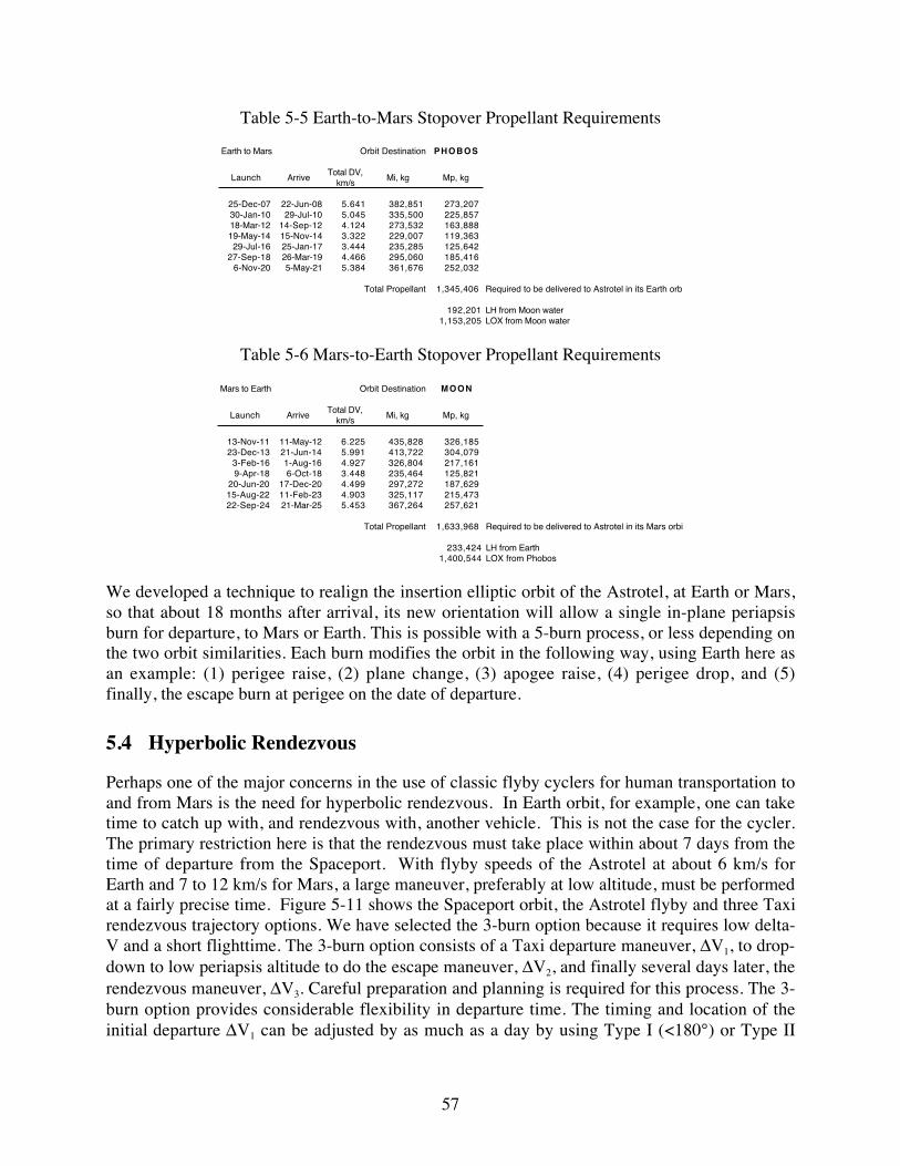
57
Table 5-5 Earth-to-Mars Stopover Propellant Requirements
Earth to Mars Orbit Destination PHOBOS
Launch ArriveTotal DV,
km/sMi, kg Mp, kg
25-Dec-07 22-Jun-08 5.641 382,851 273,207 30-Jan-10 29-Jul-10 5.045 335,500 225,857 18-Mar-12 14-Sep-12 4.124 273,532 163,888 19-May-14 15-Nov-14 3.322 229,007 119,363 29-Jul-16 25-Jan-17 3.444 235,285 125,642
27-Sep-18 26-Mar-19 4.466 295,060 185,416 6-Nov-20 5-May-21 5.384 361,676 252,032
Total Propellant 1,345,406 Required to be delivered to Astrotel in its Earth orb
192,201 LH from Moon water1,153,205 LOX from Moon water
Table 5-6 Mars-to-Earth Stopover Propellant Requirements
Mars to Earth Orbit Destination MOON
Launch ArriveTotal DV,
km/sMi, kg Mp, kg
13-Nov-11 11-May-12 6.225 435,828 326,185 23-Dec-13 21-Jun-14 5.991 413,722 304,079
3-Feb-16 1-Aug-16 4.927 326,804 217,161 9-Apr-18 6-Oct-18 3.448 235,464 125,821
20-Jun-20 17-Dec-20 4.499 297,272 187,629 15-Aug-22 11-Feb-23 4.903 325,117 215,473 22-Sep-24 21-Mar-25 5.453 367,264 257,621
Total Propellant 1,633,968 Required to be delivered to Astrotel in its Mars orbit
233,424 LH from Earth1,400,544 LOX from Phobos
We developed a technique to realign the insertion elliptic orbit of the Astrotel, at Earth or Mars,so that about 18 months after arrival, its new orientation will allow a single in-plane periapsisburn for departure, to Mars or Earth. This is possible with a 5-burn process, or less depending onthe two orbit similarities. Each burn modifies the orbit in the following way, using Earth here asan example: (1) perigee raise, (2) plane change, (3) apogee raise, (4) perigee drop, and (5)finally, the escape burn at perigee on the date of departure.
5.4 Hyperbolic Rendezvous
Perhaps one of the major concerns in the use of classic flyby cyclers for human transportation toand from Mars is the need for hyperbolic rendezvous. In Earth orbit, for example, one can taketime to catch up with, and rendezvous with, another vehicle. This is not the case for the cycler.The primary restriction here is that the rendezvous must take place within about 7 days from thetime of departure from the Spaceport. With flyby speeds of the Astrotel at about 6 km/s forEarth and 7 to 12 km/s for Mars, a large maneuver, preferably at low altitude, must be performedat a fairly precise time. Figure 5-11 shows the Spaceport orbit, the Astrotel flyby and three Taxirendezvous trajectory options. We have selected the 3-burn option because it requires low delta-V and a short flighttime. The 3-burn option consists of a Taxi departure maneuver, ∆V1, to drop-down to low periapsis altitude to do the escape maneuver, ∆V2, and finally several days later, therendezvous maneuver, ∆V3. Careful preparation and planning is required for this process. The 3-burn option provides considerable flexibility in departure time. The timing and location of theinitial departure ∆V1 can be adjusted by as much as a day by using Type I (<180°) or Type II

58
(>180°) transfers to periapsis where ∆V2 occurs. The primary requirement is to be at the properposition at the proper time for the ∆V2.
Spaceport Position(4-Burn) Spaceport Position
(2-Burn)
Spaceport Position(3-Burn)
Planet
Rendezvous
AstrotelTrajectory ∆V1
∆V2
Circular Orbit
∆V3
Figure 5-11 Hyperbolic Rendezvous Options in 3D
Figure 5-12 illustrates an example departure trajectory from Lunar orbit radius (LOR) in threedimensions as viewed from normal to the Moon’s orbit and from a perspective view.
View from Z-axis(Earth centered coordinates)
3D View
Earth
Lunar OrbitAstrotel Orbit
Spaceport Location
Figure 5-12 Example Hyperbolic Rendezvous from Lunar Orbit Radius in 3D
A computer program has been written to perform the three required maneuvers for hyperbolicrendezvous. Figure 5-13 illustrates a 2D version of this chart that was used in formulation of acomputer program. This program has been used to generate all hyperbolic rendezvousrequirements for the reference Aldrin cycler. It provides 3-dimensional solutions, and can bedriven by an optimization program. It also can be easily modified to provide 2- or 4-burnsolutions, where the first would be used to do a direct escape to rendezvous and the secondwould add a burn by flying to some distance from the planet to perform a plane change. Thelatter is forbidden here because of the flight time restriction. Fortunately, large plane changesare not required for the Aldrin cycler, so the 3-burn is appropriate. Because of this, closed formequations representing 2-dimensional solutions were derived and used for trajectory inputs to theMAMA program that models the transportation architecture.

59
AstrotelFlybyOrbit
SpaceportOrbit
AstrotelRendezvous
Taxi
∆V1
∆V2
∆V3
Figure 5-13 Taxi Trajectory in 2D from Spaceport to Hyperbolic Rendezvous with the Astrotel
5.5 Spaceport Location
Having to solve the hyperbolic rendezvous problem provided insight into the desired location ofthe Spaceport. As discussed above, plane changes are best made far from the planet where theorbital velocities are low. Velocity changes are best made close to the planet, in the gravity well.In LEO, the orbital velocity is almost 8 km/s, whereas at lunar distance, the velocity is about1 km/s, which is a better place to make a required plane change. The L1 libration point, whichhas the Moon's period, is closer to the Earth and was chosen for the Spaceport location inPhase I. The advantage is a lower orbital velocity than the Moon, and therefore a lower requiredplane change delta-V. The disadvantage of L1, however, is that it is tied to the Moon and has thesame period of about 28 days. For this reason, it could be in the wrong position in its orbit at thetime of the first maneuver for the hyperbolic rendezvous. For the L1 location, the Spaceportcould be almost a month away from its required position for Taxi departure. This positionmismatch can be mitigated by either high delta-V, which negatively impacts missionperformance, or very long phasing orbits, which require excessive crew time in the Taxi.
This implies that an active Spaceport is needed, that can position itself into the proper hyperbolicdeparture location, and be there at the required time. This positioning is accomplished bychanging the period of the Spaceport, which is assumed to be at about the distance of the Moon,to cause drifting to the required orbit over a period of months, and then reverting back to itsoriginal period. The velocity is proportional to drift time or about 1 m/s for 1° in longitude overa period of a month.
For Mars, the situation is different. The Spaceport, because of its other functions, particularly toaid in the in-situ production of material at Phobos has been situated in an orbit close to Phobos.Its period is about 7.5 hr, which is short enough to accommodate most launch phasingrequirements.
5.6 Cycler Orbit Sequences
The sequence of key events for the three basic architecture options was generated. The followingfigure displays a version of the comparison of key orbit events for the Aldrin Cycler, Semi-cycler

60
and Stopover trajectory options. This chart shows the approximate solar range of the Astrotel inits travel to and from Earth and Mars. The horizontal axis is time in years from 2012 to 2027.The vertical axis is offset solar radius. Each set of cyclic orbits is offset by 2 AU in order tofacilitate displaying and comparing the relative timing. For example, the top graph displays theAldrin Down Cycler (ADC). The numbers at the points of planetary flybys refer to crews beingtransferred. Approximate crew tours of duty are shown.
Cycler Orbit Sequences
0
1
2
3
4
5
6
7
8
9
10
11
12
13
14
15
12 13 14 15 16 17 18 19 20 21 22 23 24 25 26 27
Year - 2000
Off
set
Pla
net
So
lar
Rad
ius
ADC
AUC
SO2
SO1
SC1
SC2
SC3
1
2
3
4
5
6
7
1
2
3
4
5
1 2
2
3
3
4
4 5
5
6
7
1-1
0
-1 6
1
*1
2
2
3
3
4
4
5 6 7
5
~4.5 yr tours
~5 yr tours
~4.5 yr tours
Mars
Earth
Ald
rin
Cyc
lers
Sto
po
vers
Sem
i-C
ycle
rs
*Numbers refer to example crews
Figure 5-14 Cycler Orbit Sequences
5.7 Low-thrust Cargo Transport Orbit Sequences and Timing
A practical option is to transport cargo to Mars and continuously cycling Astrotels via reusableCargo Freighters. An example Astrotel Cargo Freighter trajectory was analyzed. The Earthlaunch date is October 11, 2023 with return to Earth on May 14, 2027. This analysis resulted in aflight time (including planetocentric spirals of 966 days) to the Astrotel, only 335 days back toLEO for total round-trip flight time from LEO of 1311 days. Total propulsion on time is 608days and there is an Earth turnaround time of 304 days before departure to the Astrotel again. Forthis analysis, total assumed payload mass delivered in 15 years was set at about 88 mt. Scalablemass fractions at the optimal power-to-initial mass ratio of 10 W/kg at 1 AU were 0.6016 for thepayload-to-initial mass ratio and 0.2769 for the propellant-to-initial mass ratio. The followingtable describes the initial, payload, propellant and propulsion/power system masses and the solararray size as a function of number of sorties to the Astrotel in 15 years given the assumed cargoto be transported.

61
Table 5-7 Astrotel Cargo Freighter Parameters vs Number of Sorties in 15 years
# of Sorties
Po (kWe @ 1AU)
Mo (kg) Mps
(kg)ΣMp
(kg)
0.15*ΣMp
(kg)Mcargo (kg)
7 211 21,104 1,688 5,843 877 12,6966 246 24,621 1,968 6,818 1,023 14,8125 295 29,545 2,360 8,183 1,228 17,7744 369 36,932 2,952 10,228 1,534 22,2183 492 49,240 3,936 13,636 2,045 29,623
An example Mars Cargo Freighter orbit was analyzed. For cargo transport to the Mars Spaceportanalysis the Earth launch date was January 5, 2011 with Earth return date of October 26, 2014.This analysis resulted in a flight time to Mars of 753 days (including a 263 day Earth escapespiral and 90 Mars capture spiral). A stay time of 178 days at the Mars Spaceport days wasassumed followed by flight time of 459 days back to LEO (including a 22 day Mars escape spiraland 37 day Earth capture spiral). Total round-trip flight time from LEO is 1390 days. Totalpropulsion on time is 733 days and there is an Earth turnaround time of 140 days beforedeparture to the Mars Spaceport again. For this analysis, total derived payload mass delivered ineach opportunity was between 6-17 mt. Scalable mass fractions at the optimal power-to-initialmass ratio of 10 W/kg at 1 AU were 0.5753 for the payload-to-initial mass ratio and 0.2997 forthe propellant-to-initial mass ratio. The following table describes the initial, propellant andpropulsion/power system masses and the solar array size as a function of cargo mass to the MarsSpaceport delivered in each opportunity. Note this table only goes to a 30-mt payload level, butthe results are directly scalable to higher payload mass values. In addition, these numbers assumeall structure and spacecraft bus avionics are included in Mps.
Table 5-8 Mars Cargo Freighter Parameters as a Function of Cargo Mass
Po (kWe
@ 1AU)Mo (kg) Mps (kg) ΣMp (kg) 0.15*Σ
Mp (kg)Mcargo
(kg)
100 10,000 800 2,997 450 5,753150 15,000 1,200 4,496 674 8,630200 20,000 1,600 5,994 899 11,507250 25,000 2,000 7,492 1,124 14,384300 30,000 2,400 8,990 1,349 17,261
The nominal plan is to have two Astrotel Cargo Freighters for the Astrotels (one for eachAstrotel), each delivering cargo every other opportunity and two to four Cargo Freighters for theMars Spaceport (one or two leaving every opportunity). This plan ensures a cargo delivery everyMars opportunity and every other opportunity for each Astrotel thus potentially building in somereliability and margin.

62
The tables below summarizes the a full 15 years of operations of the Mars and Astrotel CargoFreighters from Earth to their respective targets including stay time at the target prior to return toEarth. The assumptions for this global analysis was somewhat different than the analysis aboveresulting is somewhat difference timing. Note that there are two vehicles in operation at any onetime in order to ensure full resupply to the Mars elements of the architecture, hence Vehicle 1operates ever other opportunity. Two dates are shown, namely the Julian date (above) and thecalendar date (below). IP refers to the interplanetary phases. Refurbishment time is shown, whichcorresponds to the stay time at Earth prior to the next trip to Mars or the Astrotel. Table 5-9summarizes trajectory-related information for the Astrotel Cargo Freighter. Table 5-10summarizes similar information for the Mars Cargo Freighter.
Table 5-9 Sequence for the Astrotel Cargo FreighterAstrotel Resupply Freighter Mission Timelines
OutboundOpp Begin Spiral Start IP Begin Spiral Stay Begin Spiral Start IP Begin Spiral LEO Refurb
Spiral Days IP On Off Days Spiral Days Days Spiral Days IP On Off Days Spiral Days Arrival Time+10 +271 +132 +163
2011 2455515 265 2455780 2455790 2456051 700 2456480 0 10 2456490 0 2456490 2456622 2456653 300 2456790 35 2456825 2371 11/14/10 8/6/11 8/16/11 5/3/12 7/6/13 7/16/13 7/16/13 11/25/13 12/26/13 5/12/14 6/16/14
2015 2457062 263 2457325 2457335 2457596 700 2458025 0 10 2458035 0 2458035 2458167 2458198 300 2458335 35 2458370 2803 2/8/15 10/29/15 11/8/15 7/26/16 9/28/17 10/8/17 10/8/17 2/17/18 3/20/18 8/4/18 9/8/18
2020 2458650 263 2458913 2458923 2459184 700 2459613 0 10 2459623 0 2459623 2459755 2459786 300 2459923 35 2459958 2715 6/15/19 3/4/20 3/14/20 11/30/20 2/2/22 2/12/22 2/12/22 6/24/22 7/25/22 12/9/22 1/13/23
2024 2460229 266 2460495 2460505 2460766 700 2461195 0 10 2461205 0 2461205 2461337 2461368 300 2461505 35 2461540 2037 10/11/23 7/3/24 7/13/24 3/31/25 6/3/26 6/13/26 6/13/26 10/23/26 11/23/26 4/9/27 5/14/27
2028 2461743 264 2462007 2462017 2462278 700 2462707 0 10 2462717 0 2462717 2462849 2462880 300 2463017 35 2463052 2982 12/3/27 8/23/28 9/2/28 5/21/29 7/24/30 8/3/30 8/3/30 12/13/30 1/13/31 5/30/31 7/4/31
2033 2463350 263 2463613 2463623 2463884 700 2464313 0 10 2464323 0 2464323 2464455 2464486 300 2464623 35 2464658 2584 4/27/32 1/15/33 1/25/33 10/13/33 12/16/34 12/26/34 12/26/34 5/7/35 6/7/35 10/22/35 11/26/35
2037 2464916 265 2465181 2465191 2465452 700 2465881 0 10 2465891 0 2465891 2466023 2466054 300 2466191 35 2466226 2236 8/10/36 5/2/37 5/12/37 1/28/38 4/2/39 4/12/39 4/12/39 8/22/39 9/22/39 2/6/40 3/12/40
Mo (mt) = 33.5 Po (kWe) = 335.5 Mp min (mt) = 9.1 Mp max (mt) = 9.499 Alpha (kg/kWe) = 8
InboundOpp Begin Spiral Start IP Begin Spiral Stay Begin Spiral Start IP Begin Spiral LEO Refurb
Spiral Days IP On Off On Off Days Spiral Days Days Spiral Days IP On Off Days Spiral Days Arrival Time+36 +303.1 +667 +700 +161.8 +194.6
2010 2454947 263 2455210 2455246 2455513 2455877 2455910 700 2455910 0 10 2455920 0 2455920 2456082 2456115 300 2456220 35 2456255 2541 4/25/09 1/13/10 2/18/10 11/12/10 11/11/11 12/14/11 12/14/11 12/24/11 12/24/11 6/3/12 7/6/12 10/19/12 11/23/12
2014 2456509 264 2456773 2456809 2457076 2457440 2457473 700 2457473 0 10 2457483 0 2457483 2457645 2457678 300 2457783 35 2457818 2933 8/4/13 4/25/14 5/31/14 2/22/15 2/21/16 3/25/16 3/25/16 4/4/16 4/4/16 9/13/16 10/16/16 1/29/17 3/5/17
2018 2458111 264 2458375 2458411 2458678 2459042 2459075 700 2459075 0 10 2459085 0 2459085 2459247 2459280 300 2459385 35 2459420 2385 12/23/17 9/13/18 10/19/18 7/13/19 7/11/20 8/13/20 8/13/20 8/23/20 8/23/20 2/1/21 3/6/21 6/19/21 7/24/21
2022 2459658 263 2459921 2459957 2460224 2460588 2460621 700 2460621 0 10 2460631 0 2460631 2460793 2460826 300 2460931 35 2460966 2067 3/19/22 12/7/22 1/12/23 10/6/23 10/4/24 11/6/24 11/6/24 11/16/24 11/16/24 4/27/25 5/30/25 9/12/25 10/17/25
2027 2461172 263 2461435 2461471 2461738 2462102 2462135 700 2462135 0 10 2462145 0 2462145 2462307 2462340 300 2462445 35 2462480 2752 5/11/26 1/29/27 3/6/27 11/28/27 11/26/28 12/29/28 12/29/28 1/8/29 1/8/29 6/19/29 7/22/29 11/4/29 12/9/29
2031 2462755 266 2463021 2463057 2463324 2463688 2463721 700 2463721 0 10 2463731 0 2463731 2463893 2463926 300 2464031 35 2464066 2944 9/10/30 6/3/31 7/9/31 4/1/32 3/31/33 5/3/33 5/3/33 5/13/33 5/13/33 10/22/33 11/24/33 3/9/34 4/13/34
2035 2464360 265 2464625 2464661 2464928 2465292 2465325 700 2465325 0 10 2465335 0 2465335 2465496 2465529 300 2465635 35 2465670 1876 2/1/35 10/24/35 11/29/35 8/22/36 8/21/37 9/23/37 9/23/37 10/3/37 10/3/37 3/13/38 4/15/38 7/30/38 9/3/38
Thruster Activity
Thruster Activity
Thruster Activity
Thruster Activity

63
Table 5-10 Sequence for the Mars Cargo Freighter
Mars Resupply Freighter Mission TimelinesVehicle 1
Begin Spiral Start IP Begin Spiral Begin Spiral Start IP Begin Spiral LEO RefurbSpiral Days IP On Off On Off Days Spiral Days Stay Spiral Days IP On Off On Off Days Spiral Days Arrival Time
+0 +169 +276 +400 +0 +30 +394 +4002011 2455642 189.8 2455832 2455832 2456001 2456108 2456232 400 2456232 48.4 233 2456512 0.7 2456513 2456513 2456543 2456907 2456913 400 2456913 16.5 2456930 249
3/21/11 9/27/11 9/27/11 3/14/12 6/29/12 10/31/12 10/31/12 8/7/13 8/8/13 8/8/13 9/7/13 9/6/14 9/12/14 9/12/14 9/29/14
2016 2457179 184.6 2457363 2457363 2457532 2457639 2457763 400 2457763 48.6 274 2458086 0.8 2458087 2458087 2458117 2458481 2458487 400 2458487 16.5 2458503 285.86/5/15 12/6/15 12/6/15 5/23/16 9/7/16 1/9/17 1/9/17 11/28/17 11/29/17 11/29/17 12/29/17 12/28/18 1/3/19 1/3/19 1/19/19
2020 2458789 184.6 2458974 2458974 2459143 2459250 2459374 400 2459374 48.4 265 2459687 0.7 2459688 2459688 2459718 2460082 2460088 400 2460088 16.5 2460104 236.911/1/19 5/4/20 5/4/20 10/20/20 2/4/21 6/8/21 6/8/21 4/17/22 4/18/22 4/18/22 5/18/22 5/17/23 5/23/23 5/23/23 6/8/23
2024 2460341 195.2 2460537 2460537 2460706 2460813 2460937 400 2460937 48.4 229 2461214 0.7 2461215 2461215 2461245 2461609 2461615 400 2461615 16.5 2461631 237.11/31/24 8/14/24 8/14/24 1/30/25 5/17/25 9/18/25 9/18/25 6/22/26 6/23/26 6/23/26 7/23/26 7/22/27 7/28/27 7/28/27 8/13/27
2029 2461869 185.6 2462054 2462054 2462223 2462330 2462454 400 2462454 48.5 247 2462750 0.7 2462750 2462750 2462780 2463144 2463150 400 2463150 16.5 2463167 275.34/7/28 10/9/28 10/9/28 3/27/29 7/12/29 11/13/29 11/13/29 9/5/30 9/5/30 9/5/30 10/5/30 10/4/31 10/10/31 10/10/31 10/27/31
2033 2463442 185.5 2463628 2463628 2463797 2463904 2464028 400 2464028 48.5 285 2464362 0.7 2464362 2464362 2464392 2464756 2464762 400 2464762 16.5 2464779 258.77/28/32 1/30/33 1/30/33 7/18/33 11/2/33 3/6/34 3/6/34 2/3/35 2/3/35 2/3/35 3/5/35 3/3/36 3/9/36 3/9/36 3/26/36
2037 2465037 188.2 2465226 2465226 2465395 2465502 2465626 400 2465626 48.3 241 2465915 0.7 2465915 2465915 2465945 2466309 2466315 400 2466315 16.5 2466332 231.812/9/36 6/16/37 6/16/37 12/2/37 3/19/38 7/21/38 7/21/38 5/6/39 5/6/39 5/6/39 6/5/39 6/3/40 6/9/40 6/9/40 6/26/40
Mo (mt) = 59.66 Po (kWe) = 600 Mp min (mt) = 12.6 Mp max (mt) = 15.527 Alpha (kg/kWe) = 8
Vehicle 2Begin Spiral Start IP Begin Spiral Begin Spiral Start IP Begin Spiral LEO RefurbSpiral Days IP On Off On Off Days Spiral Days Stay Spiral Days IP On Off On Off Days Spiral Days Arrival Time
+0 +169 +276 +400 +0 +30 +394 +4002014 2456408 185.6 2456593 2456593 2456762 2456869 2456993 400 2456993 48.5 247 2457289 0.7 2457289 2457289 2457319 2457683 2457689 400 2457689 16.5 2457706 275.3
4/25/13 10/27/13 10/27/13 4/14/14 7/30/14 12/1/14 12/1/14 9/23/15 9/23/15 9/23/15 10/23/15 10/21/16 10/27/16 10/27/16 11/13/16
2018 2457981 185.5 2458167 2458167 2458336 2458443 2458567 400 2458567 48.5 285 2458901 0.7 2458901 2458901 2458931 2459295 2459301 400 2459301 16.5 2459318 258.78/15/17 2/17/18 2/17/18 8/5/18 11/20/18 3/24/19 3/24/19 2/21/20 2/21/20 2/21/20 3/22/20 3/21/21 3/27/21 3/27/21 4/13/21
2022 2459576 188.2 2459765 2459765 2459934 2460041 2460165 400 2460165 48.3 241 2460454 0.7 2460454 2460454 2460484 2460848 2460854 400 2460854 16.5 2460871 231.812/27/21 7/4/22 7/4/22 12/20/22 4/6/23 8/8/23 8/8/23 5/23/24 5/23/24 5/23/24 6/22/24 6/21/25 6/27/25 6/27/25 7/14/25
2026 2461103 189.8 2461293 2461293 2461462 2461569 2461693 400 2461693 48.4 233 2461973 0.7 2461974 2461974 2462004 2462368 2462374 400 2462374 16.5 2462391 2493/3/26 9/9/26 9/9/26 2/25/27 6/12/27 10/14/27 10/14/27 7/20/28 7/21/28 7/21/28 8/20/28 8/19/29 8/25/29 8/25/29 9/11/29
2031 2462640 184.6 2462824 2462824 2462993 2463100 2463224 400 2463224 48.6 274 2463547 0.8 2463548 2463548 2463578 2463942 2463948 400 2463948 16.5 2463964 285.85/18/30 11/18/30 11/18/30 5/6/31 8/21/31 12/23/31 12/23/31 11/10/32 11/11/32 11/11/32 12/11/32 12/10/33 12/16/33 12/16/33 1/1/34
2035 2464250 184.6 2464435 2464435 2464604 2464711 2464835 400 2464835 48.4 265 2465148 0.7 2465149 2465149 2465179 2465543 2465549 400 2465549 16.5 2465565 23710/14/34 4/17/35 4/17/35 10/3/35 1/18/36 5/21/36 5/21/36 3/30/37 3/31/37 3/31/37 4/30/37 4/29/38 5/5/38 5/5/38 5/21/38
2039 2465802 195.2 2465998 2465998 2466167 2466274 2466398 400 2466398 48.4 229 2466675 0.7 2466676 2466676 2466706 2467070 2467076 400 2467076 16.5 2467092 2371/13/39 7/28/39 7/28/39 1/13/40 4/29/40 8/31/40 8/31/40 6/4/41 6/5/41 6/5/41 7/5/41 7/4/42 7/10/42 7/10/42 7/26/42
Thruster Activity Thruster Activity
Thruster ActivityThruster Activity
Opp
Opp
5.8 Applications of Astrotel Orbit Concepts
Applications of Astrotel orbit concepts occur for high Earth orbit (HEO) operations, high Marsorbit (HMO) operations, in design techniques using combinations of hyperbolic rendezvous andlow-thrust propulsion for HEDS and robotic exploration missions. HEO could be a departurepoint to deep space for missions to Mars and asteroids, Lagrange points and for lunarexploration. In addition, there are servicing missions for near-Earth science observatories, e.g.SIRTF. For HMO Operations, one can enter regions of near-Mars space where perturbations candramatically change satellite motion and/or use low-thrust propulsion to direct perturbations touseful function. Some examples include adding or subtracting orbit energy to return to the Marssurface or to escape for Earth return, performing orbit modification to achieve a desired futureposition and velocity, e.g. for rendezvous, or for helping to stabilize distant locations forcommunication and observation spacecraft. New trajectory design techniques usingcombinations of hyperbolic rendezvous and low-thrust propulsion can be applied to transfergeosynchronous satellites to high “junk yard” orbits and LEO/lunar cargo transfer. Hyperbolicrendezvous and low-thrust concepts can be applied to for robotic exploration missions includingMars sample return, University micro-scout Mars explorers, and asteroid missions.

64
6 Aero-assist Studies
6.1 Introduction
This section summarizes the aero-assist studies carried out during Phase I and discusses the newwork done in Phase II to date.
6.2 Phase I Study Summary
In the Phase I Astrotel Study, aerocapture analysis was performed of the Taxi at Earth and Mars.Though Earth aerocapture was found to drive aeroshell thermal design, Earth aerocapture wasfound to require lower g-loads than at Mars aerocapture. A Taxi vehicle design was selected thathad a raked elliptical cone shaped aeroshell with a maximum L/D of 0.63. This vehicle wassufficient to provide the required centripetal force at the initial horizontal flight part of anaerocapture for all Mars aerocapture opportunities. It was found, however, that at the highestentry speed (12.5 km/s), the Taxi vehicle was required to be at a low altitude to achieve theappropriate level of lift-generated centripetal force in order to remain in the atmosphere. At thislevel of aero-cruise the total aerodynamic g-load (lift and drag) was found to be about 7 Earthgee, which was assumed excessive for the crew. A number of strategies were analyzed in orderto reduce the crew g-loads for these highest entry speed opportunities. These strategies included1) descending into the atmosphere at a shallow angle and using drag to reduce velocity beforereaching aero-cruise altitude, 2) a steeper entry angle to bleed off more speed prior to aero-cruise, 3) the use of a ballute device at entry, 4) the reduction of velocity by propulsive meansbefore entry, 5) propulsive thrusting in the velocity direction (which is very counter-intuitive)during the initial aero-cruise phase, and 6) allowing only experienced and exceptionally fit crewsfly those opportunities. Studies showed that propulsive thrusting at about 1 gee in the generalvelocity direction could reduce this peak initial g-load below 5 gees.
The atmospheric entry of the Mars Shuttle was also analyzed and it was determined that thedesign originally proposed by the NCOS study was robust enough, given current technology, toallow direct entry into the Martian atmosphere. Direct entry eliminates a modest delta-V requiredto first circularize the vehicle prior to entry targeting and thus reduces Phobos propellantproduction requirements and its storage at the Mars Spaceport.
6.3 Taxi Aerocapture Studies
Studies and simulations were carried out to understand the aerocapture maneuver at Mars and atEarth. Figure 6-1 displays a schematic of the Taxi aerocapture maneuver at Mars.

65
Figure 6-1 Schematic of Aerocapture Maneuver at Mars
6.3.1 Mars Aerocapture Analysis
In Phase II we have determined that level flight for Mars aerocapture will use roll control of theTaxi at fixed angle of attack (AOA). The Mars requirements dictate that the AOA will be set formaximum L/D. The conventional guidance process calls for an initial period of quasi-equilibrium glide to evaluate the error in entry angle, if any, and apparent variation of theatmospheric density and scale height from the values expected. Generally one corrective rollangle position will be used, with a roll reversal if needed to reduce the cross-track deviation to anacceptable level.
Several runs were made of our integrating simulation software in an attempt to develop andunderstand the technique for generation of aerocapture profiles in order to be able to automate itvia the computer model. The main control variable is the Bank Angle that rotates the lift vectorto be able to modulate the level of lift relative to the vertical.
The following figures display several parameters from a Taxi aerocapture trajectory simulation(with manual guidance) that results in a velocity that would take the Taxi to the radius of Phobosorbit. The Taxi was assumed to have an entry mass of 22,380 kg and a diameter of 12 m. Forthis profile the Angle of Attack (AOA) is fixed at –20 degrees for a lift coefficient of 0.60 and adrag coefficient of 0.95. The AOA is the difference between where the axis of symmetry of theaeroshell is pointed relative to the direction of the air flowing past the aeroshell. At zero AOAthere is no lift. For particular values of AOA, the lift varies with drag. Angle of Bank (AOB) isdefined as the roll angle about the wind or ram direction. Convention is that when AOB is 180°the lift is pointed positive toward the planet. Initially the AOB is set at 180° or full lift downtowards Mars in an attempt to offset the centrifugal forces trying to throw the vehicle out of theatmosphere. After reaching the approximate altitude for aero-cruise, the AOB is adjusted to 90°putting all the lift in the horizontal direction, essentially zeroing out the vertical component of

66
lift. After about 30 s, the AOB is moved to about 130° creating enough vertical component of lifttoward Mars to offset centrifugal forces. The AOB is adjusted as needed throughout aero-cruiseuntil the required budget of velocity is lost (at ~250 s) where upon the AOB rolls to zero to alignthe lift vector away from Mars so that the Taxi swiftly leaves the atmosphere on its way toPhobos.
Altitude vs Time
0
20,000
40,000
60,000
80,000
100,000
120,000
140,000
160,000
0 50 100 150 200 250 300 350 400 450 500
Time, s
Alt
itu
de, m
Aerocruise
Figure 6-2 Taxi Mars Aerocapture Altitude Profile
Altitude vs Range
0
50,000
100,000
150,000
200,000
250,000
0 500 1000 1500 2000 2500 3000
Range, km
Alt
itu
de,
m
Figure 6-3 Taxi Mars Aerocapture Altitude vs. Range Profile

67
Velocity vs. Time
0
2,000
4,000
6,000
8,000
10,000
12,000
14,000
0.00 50.00 100.00 150.00 200.00 250.00 300.00 350.00 400.00 450.00 500.00
Time, s
Vel
oci
ty, m
/s
Figure 6-4 Taxi Mars Aerocapture Velocity Profile
Flight Path Angle vs Time
-15.00
-10.00
-5.00
0.00
5.00
10.00
15.00
0.00 50.00 100.00 150.00 200.00 250.00 300.00 350.00 400.00 450.00 500.00
Time, s
Flig
ht
Pat
h A
ng
le, d
eg
Figure 6-5 Taxi Mars Aerocapture Flight Path Angle Profile

68
Angle of Attack and Bank vs Time
-30
0
30
60
90
120
150
180
210
0.00 50.00 100.00 150.00 200.00 250.00 300.00 350.00 400.00 450.00 500.00
Time, s
An
gle
s, d
eg
AOA (deg)
AOB (deg)
Figure 6-6 Taxi Mars Aerocapture Angle of Attack and Bank Angle Profiles
Heating vs Time
-10
0
10
20
30
40
50
60
70
80
90
100
110
120
130
0 50 100 150 200 250 300 350 400 450 500
Time, s
Hea
tin
g, W
/cm
2
Figure 6-7 Heat Load vs. Time

69
Overall g-load vs. Time
-4.00
-3.00
-2.00
-1.00
0.00
1.00
2.00
3.00
4.00
5.00
6.00
7.00
8.00
9.00
10.00
0.00 50.00 100.00 150.00 200.00 250.00 300.00 350.00 400.00 450.00 500.00
Time, s
g-l
oad
, gee
Total g-load (g's)
Glift Mag (g's)
Glift-vert (g's)
Gdrag (g's)
Figure 6-8 Various components of g-load vs. Time
As can be seen in Figure 6-8, overall g-load exceeds the maximum of 5. As discussed earlier,Phase I studies indicated that for the highest entry speed of 12.5 km/s, the Taxi needs toincorporate thrust maneuvers during the aerocapture in order to keep g-loads below 5. In additionthe vehicle attitude needs to be trimmed to ensure the maximum lift/drag ratio of 0.63 and itneeds to enter the atmosphere initially with full lift down. This orientation of the lift vector willavoid a major attitude change in the short time period before it reaches the level flight altitude,estimated to be about 50 km. As the measured onboard aero deceleration (lift and drag) rises toapproach the g-load limit level adopted as 5, the engine is burned at a level of thrust of about 1.5gee at angle about 45° to the vertical in a direction to reduce the aero drag. When the measuredg-load falls below 5 the engine thrust is reduced and soon brought to zero. Thereafter, control oflevel flight is achieved by rolling the vehicle at fixed AOA to maintain level flight. As the speedreduces the roll angle moves from downward (180°) towards 90° (horizontal lift). At a speed ofabout 4.5 km/s the taxi applies full lift up (roll angle 0°) and exits the atmosphere on its way upto the orbit radius of Phobos.
A brief analysis was done to assess the possibility of reducing the entry speed at Mars by use of aballute in the initial low-density portion of the atmospheric pass. It was found, however, that theentry path length, the short entry time, and the limit of 5 g-load effectively limit the delta-V thatcan be achieved by a ballute to about 1000-1500 m/s for any reasonable size and mass of ballutesystem.
The next set of charts displays aerocapture parameters for a lower entry speed for which themaximum g-load is 5.
70
6.3.2 Earth Aerocapture Analysis
At Earth, the delta-V to be lost in aerocapture is relatively small (the entry speed is about11.5 km/s and the desired exit speed to go to an apoapsis at the orbit radius of the Moon is about10.8 km/s). Preliminary studies indicate that the full lift of the taxi is not required, because therewill be an entry corridor of several degrees (in the range about 4° to 8°). It may be appropriateto maintain the AOA at the Mars value (for maximum L/D) but to enter with a substantialupward lift, e.g., a roll angle of 45°, and adjust roll angle as the onboard measurementsdetermine the actual entry angle. A target altitude for level flight at Earth is about 80 km. At theentry speed of 11.5 km/s, a downward lift acceleration of about 1 gee added to gravity willmaintain level flight. Since the period of aero-cruise in the atmosphere is much shorter at Earththan at Mars, the Taxi will simply execute the conventional guidance process that is a quasi-equilibrium glide at initial entry and a computed roll angle for the exit portion of the atmosphericpass.
6.4 Mars Shuttle Entry Analysis
In Phase II the Mars Shuttle vehicle has been studied, assuming a general Viking/Pathfindershape that has a peak lift-to-drag (L/D) ratio of about ±0.3. The advantages of this shape aresignificant space and volume for crew, fuels and cargoes and the existence of significanttechnological heritage. The Mars Shuttle deploys a large surface for entry that folds up againstthe vehicle for ascent to provide a smaller cross-section and reduced drag.
6.4.1 Entry Orbit
Entry profiles were evaluated for atmospheric entry from a 500-km circular orbit and also fordirect entry from Phobos orbit radius (POR) for which the entry speeds are about 3.6 km/s and4.2 km/s, respectively. We analyzed the expected accuracy of a de-orbit from POR (about 500m/s) and determined that the resultant entry angle accuracy would be about 0.2 deg, anacceptable value. Figure 6-9 displays the entry angle as a function of the vacuum periapsisaltitude. Direct de-orbit, as opposed to going into an intermediate orbit, results in a savings ofabout 500 m/s. Figure 6-10 shows this de-orbit delta-V at POR as a function of vacuum periapsisaltitude.

71
Mars Shuttle: Entry Angle vs Vacuum Periapsis Altitude
0
2
4
6
8
10
12
14
16
-250 -200 -150 -100 -50 0 50 100
Vacuum periapsis altitude, km
En
try
ang
le,
deg
at
alti
tud
e 12
5 km
Figure 6-9 Entry Angle vs. Vacuum Periapsis Altitude for Entry from Phobos Orbit Radius
Mars Shuttle: Delta-V at Phobos vs Vacuum Periapsis Altitude
0.550
0.560
0.570
0.580
0.590
0.600
0.610
0.620
-250 -200 -150 -100 -50 0 50 100 150
Vacuum periapsis altitude, km
Del
ta-V
at
Ph
ob
os,
km
/s
Figure 6-10 Delta-V at Phobos Orbit Radius vs. Vacuum Periapsis Altitude

72
6.4.2 Lift-to-Drag Analysis
Mars Shuttle trajectories were evaluated with constant L/D values of ±0.3 and 0 at entry anglesbetween 7 and 11 deg. The L/D = -0.3 cases generally give excessively high peak g-loads duringentry, which means that the Mars Shuttle will likely employ a fixed L/D somewhere in the range0 to +0.3. The following figures display a number of entry parameters as a function of L/D andentry angle, from entry to the point where the speed has dropped to 500 m/s, including altitude atMach 2; maximum aerodynamic g-load; range; and peak reference stagnation heating rate (for a1-m diameter reference sphere).
0
2
4
6
8
10
12
14
16
18
7 8 9 10
Entry angle, deg
Alt
itu
de
at M
ach
2,
km
L/D = -0.3
L/D = 0.0
L/D = 0.3
Figure 6-11 Altitude at Mach 2 as a Function of Entry Angle
0
1
2
3
4
5
6
7
8
9
7 8 9 10
Entry angle, deg
Ma
x A
ero
g-l
oa
d
L/D = +0.3
L/D = 0.0
L/D = -0.3
Figure 6-12 Maximum Aerodynamic g-load as a Function of Entry Angle

73
0
500
1000
1500
2000
2500
7 8 9 10
Entry Angle, deg
Ran
ge,
km
L/D = -0.3
L/D = 0.0
L/D = 0.3
Figure 6-13 Range as a Function of Entry Angle
8
10
12
14
16
18
20
22
24
7 8 9 10
Entry Angle, deg
Pea
k R
efer
ence
S
tag
nat
ion
Po
int
Hea
tin
g R
ate,
W
/cm
2
L/D = -0.3
L/D = 0.0L/D = 0.3
Figure 6-14 Peak Reference Stagnation Point Heating as a Function of Entry Angle

74
6.4.3 Entry Profile
A typical entry profile is displayed in the following figures for L/D = 0, ballistic coefficient of100 kg/m2 and nominal entry angle of 8° at an entry interface altitude 125 km. Entry trajectoriesfor a ballistic coefficient in the range B = 30 to 120 kg/m2 (B = m/CdA, where m is the mass, Cd
is the drag coefficient, and A is the cross sectional area) were examined. A nominal B = 100kg/m2 (the current design is at B = 70 kg/m2) was chosen for evaluation of the peak entry heatingrate and calculating the required delta-V for landing. The peak-heating rate for a vehicle withnose radius 9 m (about the maximum for this case) is about 3 W/cm2. This peak heating valuecan be radiated at a surface temperature of about 900 K, at an emissivity of 0.8, or by use of anablating low-temperature thermal protection system (TPS). Targeting to a surface point will beachieved by using the customary roll angle control modulation to adjust the vertical componentof lift. The range variation attainable is considerably more than is needed to compensate for entryangle errors and expected atmospheric density variations.
Mars Shuttle entry from Phobos Vei=4210 m/s at Z = 125 km L/D=0 Vrot = 218 m/s m/CdA = 100 kg/m2 Entry angle= 8 deg Altitude km
0
20
40
60
80
100
120
140
0 50 100 150 200 250 300 350 400 450
Time, s
Alt
itu
de
, k
m
Figure 6-15 Mars Shuttle Entry: Altitude vs. Time

75
Mars Shuttle entry from Phobos Vei=4210 m/s at Z = 125 km L/D=0 Vrot = 218 m/s m/CdA = 100 kg/m2 inertial at 125 km altitude Aero G-load, gees
0
0.5
1
1.5
2
2.5
3
3.5
0 50 100 150 200 250 300 350 400 450
Time, s
Ae
ro g
-lo
ad
, g
ee
s
Figure 6-16 Mars Shuttle Entry: Aerodynamic g-load vs. Time
Mars Shuttle Entry from Phobos, 8 deg, L/D=0
0
1000
2000
3000
4000
5000
6000
7000
0 5 10 15 20 25
Time, s
Sta
gn
atio
n P
ress
ure
, N
/m^
2
Figure 6-17 Mars Shuttle Entry: Stagnation Pressure vs. Time
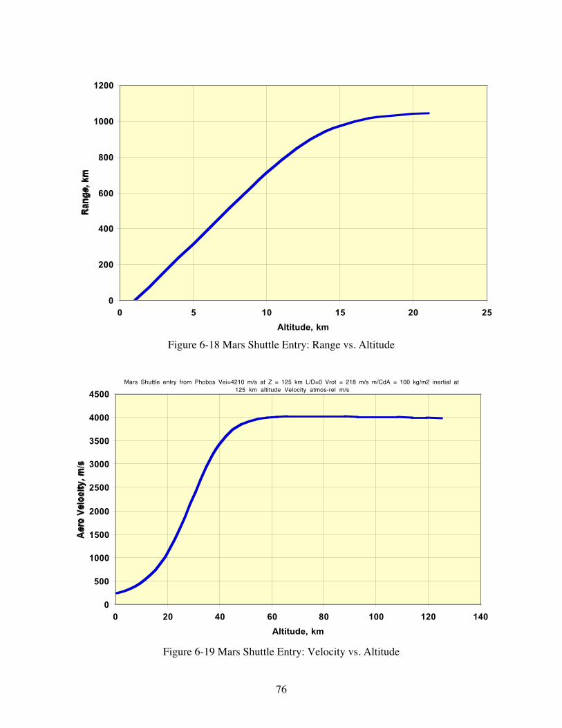
76
0
200
400
600
800
1000
1200
0 5 10 15 20 25
Altitude, km
Ra
ng
e,
km
Figure 6-18 Mars Shuttle Entry: Range vs. Altitude
Mars Shuttle entry from Phobos Vei=4210 m/s at Z = 125 km L/D=0 Vrot = 218 m/s m/CdA = 100 kg/m2 inertial at 125 km altitude Velocity atmos-rel m/s
0
500
1000
1500
2000
2500
3000
3500
4000
4500
0 20 40 60 80 100 120 140
Altitude, km
Aer
o V
elo
city
, m
/s
Figure 6-19 Mars Shuttle Entry: Velocity vs. Altitude

77
0
1000
2000
3000
4000
5000
6000
7000
0 20 40 60 80 100 120 140
Altitude, km
Sta
gn
atio
n P
ress
ure
, N
/m^
2
Figure 6-20 Mars Shuttle Entry: Stagnation Pressure vs. Altitude
6.4.4 Landing Deceleration Analysis
Landing deceleration was analyzed assuming a L/D = 0, ballistic coefficient of 100 kg/m2 andnominal entry angle of 8° at an entry interface altitude 125 km. For this analysis, a deceleratingengine burn thrust of a steady 1.5 Earth gees was applied starting at different altitudes from 10 to6 km in the descent phase. The required delta-V decreased as the burn began at lower altitudes.For the 6-km burn start case, the vehicle essentially was decelerated to zero velocity in about 2km, which consumed about 300 m/s of propellant. In the following figures, the speed and altitudeare normalized such that at zero altitude or time from landing the speed is zero. Figure 6-21shows the delta-V to decelerate with 1.5 gee, beginning at altitudes of 10, 8 and 6 km versus theentry angle. Figure 6-22 shows altitude as a function of time for a landing deceleration of 1.5gee beginning at altitude 6 km. Figure 6-23 shows the atmosphere relative speed as a function ofaltitude for a deceleration of 1.5 gee beginning at altitude 6 km. Figure 6-24 shows thedecelerating g-load as a function of time from landing for 1.5 gee beginning at altitude 6 km. Itis probable that in reality the latter part of the decelerating burn and the burns to hover and fly tothe target and to counteract wind would be combined and would use a variable thrust level. Inany event, an allocation of about 300 m/s for deceleration is considerably less than the 1000 m/sassumed in Phase I. These results mean that the number of “RL60-class” rocket engines needs tobe 3 in order to have a reserve engine in the event of a one-engine-out situation during descentfrom orbit to the surface of Mars.

78
Deceleration 1.5 gee for landing, begin at 10, 8 and 6 km altitude, L/D = 0 entry
250
270
290
310
330
350
370
390
410
430
7 8 9 10Entry angle, deg
De
lta
-V
to
Re
du
ce
Sp
ee
d t
o Z
ero
(~
La
nd
ing
D
elta
-V),
m/s
Altitude = 6 km
Altitude = 8 km
Altitude = 10 km
Figure 6-21 Landing Delta-V vs. Entry Angle and Burn Start Altitude
0
500
1000
1500
2000
2500
3000
3500
4000
0 5 10 15 20 25 30
Time from Landing, s
Alt
itu
de,
met
ers
Figure 6-22 Altitude vs. Time for Entry Angle 8°, Deceleration of 1.5 gee, Beginning at 6 km.

79
0
500
1000
1500
2000
2500
3000
3500
4000
0 50 100 150 200 250 300 350 400
Speed, m/s
Alt
itu
de
, m
ete
rs
Figure 6-23 Altitude vs. Atmosphere Relative Speed for Deceleration of 1.5 gee, Beginning at 6km, Entry Angle 8
Shuttle Deceleration 1.5 gee,begin 6 km,8 deg, L/D = 0
0
0.5
1
1.5
2
2.5
0 1 2 3 4 5 6 7 8 9 10
Time, s
G-l
oa
d,
ge
e
Figure 6-24 Deceleration g-load vs. Time from Landing for 1.5 Gee, 8° Entry Angle, Beginningat Altitude 6 km

80
6.5 Mars Shuttle Ascent Analysis
The Mars Shuttle ascent problem was first simulated with a COSPAR mean atmosphere modeland a nominal vehicle with subsonic drag coefficient Cd of 0.7. The simulation software providesfor 3 burns, with thrust along the V-vector, and gravity turning. The first two burns werecoalesced, since there is no staging, and the burns stop when it is computed that the vehicleapoapsis will reach a predetermined altitude, e.g. 125 km. The 3rd burn is brought on at somepoint and ceases when the vehicle reaches the desired apoapsis. The variable parameter that hasmost effect on the trajectory is the ascent path angle early in the ascent. If the path is too steep,the vehicle fights gravity for too long, and the burn stops with the speed low and the path steep.If the path is too shallow the vehicle fights aerodynamic drag for too long and fails to ascend toorbit. A useful metric in evaluating the performance of a particular ascent profile is to evaluatethe difference between the ideal velocity associated with the mass expulsed in reaching a circularorbit (calculated using the rocket equation or mf = mie-∆V/gIsp) and the actual velocity attained inorbit. To gain insight into the dominant parameters this difference in velocity was analyzed as afunction of the thrust/mass ratio at launch, timing and length of coast periods and the parameterm/CdA where m is the vehicle mass, Cd is the drag coefficient and A is the area. This velocitydifference or “loss” is caused by the (1) effects of the atmosphere (drag loss), (2) misalignmentbetween the velocity and thrust vectors during the burns (steering loss) and (3) burns not beinginstantaneous impulses and thus occurring over a range of planet radii (gravity loss). Gravitylosses result from a burn occurring over time and a wide variation in planet radius since avelocity change is much more effective (increases orbit energy more) if executed as close to thecenter of the planet as possible.
In the analysis carried out, a RL60-class rocket engine was assumed and a number of ascentvariables explored. These variables included initial thrust acceleration in the range about 0.8 to2.0 Earth gee, Ballistic Coefficient, m/CdA (m = mass, kg, Cd is average drag coefficient, and Ais the cross-sectional area, m2) from 60 to 1200 kg/m2, and initial flight path angle from 88° to80°. For each initial flight path angle the acceleration was varied until the total delta-V to reacha circular orbit at the radius of Phobos was determined, and the minimum Delta-V was selected.Optimum delta-V was calculated as a function of ballistic coefficient, m/CdA. Graphs of Machnumber and acceleration were also plotted versus time and altitude and shown below.
A delta-V of about 5.15 km/s results from a Cd of 0.9 (hemispherical nose cap), which could bereduced about 50 to 150 m/s if a sharper nose could be used, a ballistic coefficient of 784 kg/m2
assuming a 10-m diameter vehicle at launch with the aeroshell stowed, and a 55,423 kg launchmass. The Mach number plot indicates that the vehicle quickly goes supersonic, so that thegoverning Cd is for supersonic and hypersonic flight. The following chart displays delta-Vversus the ballistic coefficient of the vehicle. As with the descent analysis, these results meanthat the number of RL60-class” rocket engines needs to be 3 in order to have a reserve engine inthe event of a one-engine-out situation during launch and ascent from the surface of Mars. Themass ratio from launch to final orbit at Phobos altitude was computed with instantaneous burnsto raise the apoapsis to that of Phobos and then to circularize. First results indicate a finalmass/initial mass ratio of about 0.33.

81
Ascent to Phobos: Total Delta -V vs Ballistic Coefficient;(Equatorial launch with Mars rotation)
5.0
5.2
5.4
5.6
5.8
6.0
6.2
6.4
0 200 400 600 800 1000 1200 1400 1600
Ballistic Coefficient, B=m/CdA, kg/m2
To
tal
Del
ta-V
to
Cir
cula
rize
at
Ph
ob
os,
km
/s
Figure 6-25 Delta-V versus Ballistic Coefficient
The next figure displays the Mars Shuttle altitude versus time for the launch to Phobos.
Mars Shuttle Ascent: Time vs Altitude
0
20,000
40,000
60,000
80,000
100,000
120,000
140,000
0 50 100 150 200 250 300
Time, s
Alt
itu
de,
m
Figure 6-26 Ascent Time versus Altitude
The next charts show the Mars Shuttle velocity as a function of time.

82
Mars Shuttle Ascent to Phobos Circular
0
500
1000
1500
2000
2500
3000
3500
4000
4500
0 50 100 150 200 250 300
Time, s
Ve
loc
ity
, m
/s
Figure 6-27 Ascent Velocity versus Time
The g-load as a function of time for the launch profile is shown in the next chart. Note the peakg-load is at the end of the burn.
Mars Shuttle Ascent to Phobos Circular: g-load vs Time
0.0
0.5
1.0
1.5
2.0
2.5
3.0
3.5
0 50 100 150 200 250 300
Time, s
g-l
oa
d
Figure 6-28 Ascent g-load versus Time

83
The next chart displays the flight path angle as a function of time throughout the ascent phase.
Mars Shuttle ascent to circular Phobos: Gamma v Altitude
0
10
20
30
40
50
60
70
80
90
0 20,000 40,000 60,000 80,000 100,000 120,000 140,000
Altitude, m
Pa
th a
ng
le,
de
g
Figure 6-29 Ascent Flight Path Angle versus Time
The following figure charts the dynamic pressure as a function of time. Note that maximumdynamic pressure (Max Q) is about 70 s after launch.
Mars Shuttle ascent to circular Phobos: Dynamic Pressure vs. Time
0
200
400
600
800
1000
1200
0 50 100 150 200 250 300
Time, s
Dyn
amic
Pre
sure
, N
/m2
Figure 6-30 Ascent Dynamic Pressure versus Time

84
Finally the next chart displays the Mach number versus time.
Mach Number vs. Time
0
1
2
3
4
5
6
7
8
9
10
11
12
13
14
15
16
17
0 50 100 150 200 250 300
Time, s
Mac
h N
um
ber
Figure 6-31 Ascent Mach Number versus Time

85
7 Planetary Resource Utilization Systems Studies
The GAC Astrotel transportation architecture between Earth and Mars requires in-situ resourceutilization (ISRU) system to provide propellant cost effectively. The Colorado School of Mines(CSM), under the Extraterrestrial In-Situ Resource Systems Concepts Development Projectsupported the Astrotel architecture by developing a conceptual design for the ISRU supportsystem. The design proposes extraction of oxygen or water from regolith excavated from on thesurfaces of the Moon, Mars, and its moon Phobos. Further information about the ISRUconceptual design is in the appended report from CSM. Note that the numbers in bracket [XX]refer to references in the CSM Final Report in Appendix 3 of Phase II Interim Report.
7.1 In Situ Resource Utilization (ISRU) Conceptual Designs
The CSM project’s limited resources were applied primarily to the Phobos ISRU conceptualdesign. Conceptual designs from other projects underway at CSM for Lunar and Martian ISRUsystems were integrated with the Phobos design to build the overall ISRU system design forAstrotel. Note that there are small inconsistencies between the requirements for the ISRUsystems as shown in this section and the current derived MAMA ISRU requirements developedduring Phase II.
7.1.1 Mars ISRU Conceptual Design
Excavation and extraction systems for Mars must be designed to withstand the low-pressureatmosphere (560 Pa), the low gravity (3.73 m/s2) and the highly varying temperature variations(140 K to 300 K). A bucket wheel excavator (BWE) was designed for excavation of Martianregolith by Muff [35]. This design provided the baseline from which the Phobos BWE wasanalyzed. The Muff [35] BWE is sized to excavate 50 kg/hr of regolith and has a mass of 50 kg.Its dimensions are 0.58-m wide, 1.5-m long, and 0.5-m tall.
Simulation and analysis of the conceptual design made it evident that excavator geometry can bechanged to decrease excavation forces. Decreasing excavation forces meant a decrease in systemmass and power consumption. This led to an optimization of the BWE design to minimize theexcavation forces. Optimization of the conceptual design reduced the computed torque appliedto the bucket-wheel by 72% (5.39 Nm to 1.49 Nm) and the computed power consumed whileremoving regolith by 52% (0.0723 W to 0.0345 W).
Based on the results from the optimization, a prototype excavator has been designed, andfabrication of the excavator has begun. Once built, the prototype will be instrumented andexcavation control algorithms developed for laboratory scale tests. Tests will produce actualexcavation forces for model verification.

86
7.1.2 Phobos ISRU Conceptual Design
Phobos ISRU conceptual design work consisted of studies and development of a PhobosRegolith Excavator, the development of options for Phobos oxygen and water extraction andpropellant production, and Phobos Regolith carbothermal reduction.
7.1.2.1 Phobos Regolith Excavator
It is difficult to design an excavation and extraction system for Phobos since it lacks anatmosphere, the gravity is extremely low (0.005 m/s2), and the temperature variations areextremely high (150 K to 270 K). A trade study was done on proven terrestrial excavationalternatives to determine which would be most effective when modified for the Phobosenvironment which requires obstacle avoidance, rock sorting, continuous excavation duty cycle,excavator flexibility, and low mass excavation. The bucket-wheel excavator system (BWE)scored the highest. CSM Graduate Research Assistant Tim Muff built a model of anextraterrestrial BWE for Mars in the motion-solving software package, Visual NASTRANDesktop. Lee Johnson modified and used it for the Phobos excavation modeling. The model,shown in Figure 7-1, has the ability to maneuver the boom and bucket-wheel around obstacles,while screening out stones from entering the storage bin using a grating over the auger thattransports material to the bin. The BWE provides a continuous excavation duty cycle, since itcan excavate materials and simultaneously transport the materials to storage without stoppingexcavation. Excavation forces for the BWE system are primarily horizontal and provided by themass of the entire excavator instead of only the bucket mass, shown in Figure 7-2, allowing anexcavator to work in extremely low gravity without exterior anchoring, provided the mass(material and/or excavator) provides ample traction for excavation and forward movement.
Figure 7-1 Prototype Mars Bucket-Wheel Excavator Design [35]
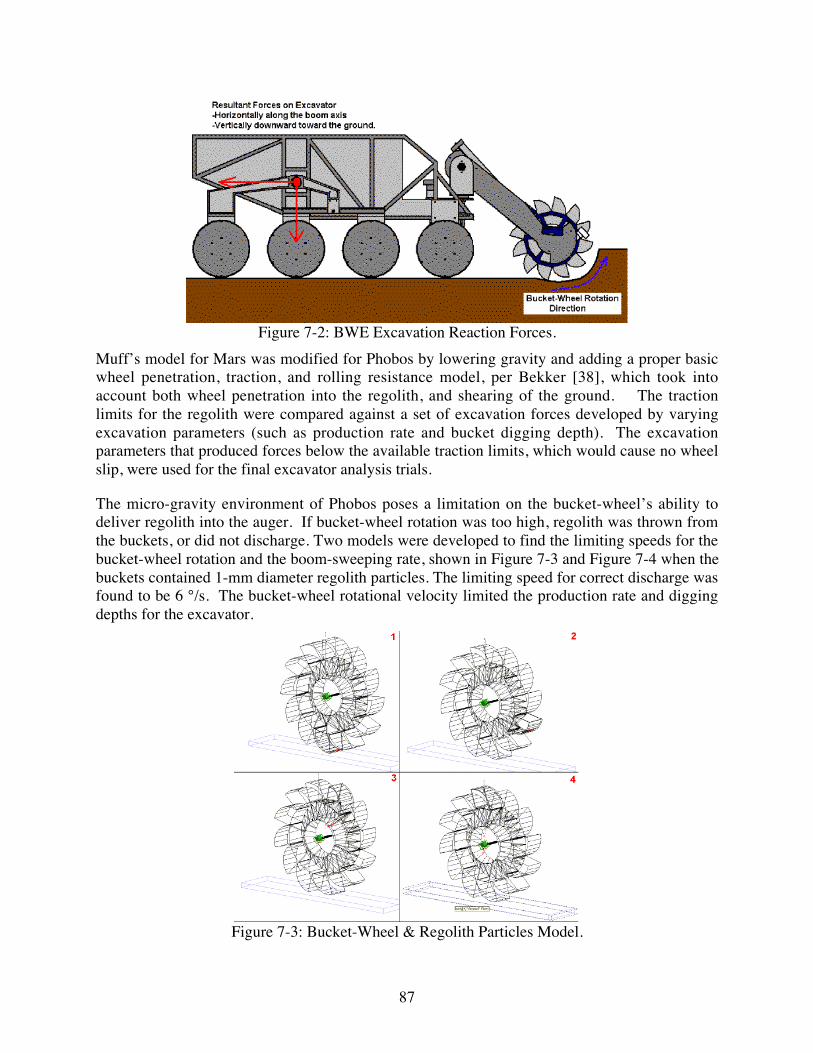
87
Figure 7-2: BWE Excavation Reaction Forces.
Muff’s model for Mars was modified for Phobos by lowering gravity and adding a proper basicwheel penetration, traction, and rolling resistance model, per Bekker [38], which took intoaccount both wheel penetration into the regolith, and shearing of the ground. The tractionlimits for the regolith were compared against a set of excavation forces developed by varyingexcavation parameters (such as production rate and bucket digging depth). The excavationparameters that produced forces below the available traction limits, which would cause no wheelslip, were used for the final excavator analysis trials.
The micro-gravity environment of Phobos poses a limitation on the bucket-wheel’s ability todeliver regolith into the auger. If bucket-wheel rotation was too high, regolith was thrown fromthe buckets, or did not discharge. Two models were developed to find the limiting speeds for thebucket-wheel rotation and the boom-sweeping rate, shown in Figure 7-3 and Figure 7-4 when thebuckets contained 1-mm diameter regolith particles. The limiting speed for correct discharge wasfound to be 6 °/s. The bucket-wheel rotational velocity limited the production rate and diggingdepths for the excavator.
Figure 7-3: Bucket-Wheel & Regolith Particles Model.

88
Figure 7-4 Bucket-Wheel/Boom & Regolith Particles Model.
Multiple BWE simulations calculated torque, instantaneous power, average power over oneboom sweep, and average power over one hour of excavation from the set of production ratesand digging depths that allowed the excavator to advance without wheel slippage. The modeladded rolling resistance and integrated to calculate the instantaneous power, average power overthe excavation period, and specific power (power per mass of material excavated). The scenariowith the highest production rate and lowest specific power respectively yielded the best set ofexcavation parameters. The optimal parameters and associated power requirements are listed inthe following table.
Table 7-1 BWE Model Characteristics for Phobos Excavation Conceptual Design.
Characteristic ValueProduction Rate (Q) 20 kg/hrForward Depth of Cut (FDOC) 0.04 mDepth of Cut (Z) 0.02 mRequired Traction 19.3 NAvailable Traction 19.8 NAverage Total Power Excavation (1 Hour) 6.29 WAverage Total Power Movement (1 Hour) 0.11 W
Future additions to the NASTRAN BWE model could include:
1) Integration of known regolith composition and physical properties from future studies of orexploration missions at Phobos.
2) Enhanced soil interaction algorithm to account for soil shearing (FEA), compaction, andexcavator wheel flotation.
3) Integration of work, power, and optimization calculations into NASTRAN Desktop.

89
4) Enhanced materials handling model of material movement and power consumption tocompare ballistic, conveyor, and pneumatic systems.
5) An excavation area model that would optimize the travel path of the excavator given power,time, and other constraints.
6) A scaling model that would optimize the BWE physical dimensions to specific excavationenvironment and constraining criteria.
7.1.2.2 Trade Studies for Phobos Oxygen and Water Extraction and Propellant Production
The Astrotel Phase I baseline assumed that only oxygen would be available from Phobos’regolith and that the regolith would be processed on Phobos. Several spreadsheets wereconstructed, based on the baseline Phobos oxygen production system run during the Phase Istudy, to assess the:
1) implications if Phobos actually has 10% extractable water in the regolith; and
2) benefit of mining regolith on Phobos and transferring it to a spaceport for processing.
The calculations for the second question were carried out for two different spaceport locationswith different ∆V requirements (100 m/s and 700 m/s) for transport from Phobos to thespaceport. These preliminary estimates can be improved when the final location of the Marsspaceport is determined. The calculations assumed that the spacecraft mass is 10% of the massof the payload that it carries, which should be sufficient as the impulse required for transferringpropellant to the spaceport is small.
The general conclusions are:
1) The production of water on Phobos requires less total mass than the production of oxygen.Although the abundance of extractable water is about 1/3 of that assumed for oxygen in thebaseline, the reactors are more efficient at lower operating temperatures and less power isrequired for extraction. The Phobos water scenario assumes that water is produced onPhobos and transferred to the spaceport for electrolysis and liquefaction. It doesn’t makesense to electrolyze water and liquefy the gases at Phobos, as water is easier to transport tothe spaceport than the cryogens and power is more available at the spaceport.
2) Transporting regolith from Phobos to a spaceport for processing was studied to determinewhether the gain of efficiency of the processing and power systems in free space wouldoffset the need for more hardware and propellant use in carrying large amounts of regolithback and forth. Production at the spaceport can be effective at small ∆V’s, but becomesunreasonable at ∆V’s greater than a few hundred m/s. It was assumed that the regolith wouldhave to be returned to Phobos after extracting the propellant, so propellant has to be providedfor both transfers. The spacecraft is not large, but at 700 m/s ∆V, the amount of propellantused to carry the regolith back and forth became nearly half of the mass of the propellant thatcould be produced from the regolith load.
In the original baseline calculation, the mass of the spacecraft transporting oxygen to thespaceport was not included. The baseline was modified to include the mass of the tanker. Assomething must be transported from Phobos to the spaceport in all scenarios, this spacecraft must

90
be included for a complete comparison of how much mass would have to be delivered to theMars system.
7.1.2.3 Phobos Regolith Carbothermal Reduction
The true composition of Phobos is unknown, however from its low albedo and density it hasbeen considered to be of a carbonaceous chondrite composition. Most carbonaceous chondritescontain bound water, but the observed reflectance spectrum of Phobos by the Russian Phobosspacecraft found no water absorption line.
Table 7-2 lists the composition of carbonaceous chondrite. Oxygen might be produced byheating the regolith, assuming that elemental carbon is available for the reduction of iron oxideand silicon dioxide. Several problems exist with this concept:
1) The amount of carbon that can be obtained by carbothermal reduction is directly related tothe carbon content. If all the carbon is converted to CO, the mass of oxygen that can beobtained is 1.3 times the mass of carbon. To obtain the 34% of regolith mass to oxygenconversion assumed by the original Astrotel concept, a carbon recovery and recycling systemis required.
2) Carbonaceous chondrite materials contain high amounts of sulfur which is an efficient foulerof catalysts that are used to convert CO to O2. A means of sulfur removal is required.
3) The composition of the gases evolved from pyrolysis of carbonaceous chondrite material willbe complex and will require a means of adjustment to simplify the reactor system.
Table 7-2 Chemical Composition of Carbonaceous Chondrite
Component %SiO2 28.23MgO 19.03FeO 12.22
C 4.43FeS 20.67
MeO* 15.42*Metal oxides, not reduced by carbothermal reduction, considered inert.
As a part of the research into the propellant production aspect of the Astrotel concept, threegroups of CSM chemical engineering students addressed the question of how oxygen may beextracted from dehydrated carbonaceous chondrite material, taking into account the issues listedabove. Their findings are:
1) The first team calculated the equilibrium gas composition to be expected when carbonaceouschondrite material is heated to different temperatures. The C/H ratios in which the Phobosregolith is heated can be adjusted to drive the released sulfur into the CS2 form. As long asthe weight ratio of carbon to sulfur in the regolith is greater than 0.2, in a reactor that recyclescarbon and hydrogen, carbon replenishment is not required. However, to reduce unwantedreactions in the effluent stream a method must be found to reduce its temperature below thatof the gas reactor.

91
2) The second team independently addressed the problem associated with the removal of sulfur(however they did not consider the possibility of CS2 removal). They considered threeapproaches:
A) Removing sulfur as molten FeS at temperatures around 1200 °C.
B) Using a modified Claus process [Gary, J.H. (1994) Petroleum Refining: Technology andEconomics. Marcel Dekker, New York] where H2S and SO2 are reacted to produce waterand elemental sulfur (a feasible process but complicated).
C) Using an absorption agent to remove H2S (extremely complex and not studied in depth).
3) The third team considered the process of taking a gas stream from the pyrolysis/sulfurremoval steps and producing oxygen. This process was based on the assumption that theincoming gas stream is a mixture of CH4 and CO. The resultant gas processing system wassized to produce 69mt/yr of O2.
From the work done, it is concluded that the production of oxygen by carbothermal reduction ofthe regolith on Phobos is feasible. Although not studied in detail, the separation of CS2 isconsidered to be the most promising approach. Preliminary mass and power estimates have beenprovided for the Astrotel MAMA model. However, several key issues require additional study:
1) Integrating carbothermal reduction reactor and gas processing systems.
2) Adapting chemical engineering processes (such as flash tanks and distillation columns) tozero gravity.
3) Designing a sulfur removal process involving the separation of CS2.
Designing the gas processing system to define the mechanisms for controlling C/H in the sulfurremoval process.
7.1.3 Lunar ISRU Conceptual Design
The discovery that Lunar Polar Regions might contain water-ice has increased the likelihood ofwater extraction from surface regolith. A senior capstone design course team designed anintegrated excavation/extraction system capable of excavating 350,000 kg/yr of polar regolith,yielding 3,500 kg/yr of water if the regolith contains 1% ice by weight. An integrated systemcould excavate the soil, heat it, remove the water, and then reject the leftover soil. Theexcavation/extraction system was constrained to a mass of 200 kg, including the power source, asize of 1 m by 0.5 m by 1 m, capable of operating in temperature ranges at the Lunar South Pole(25 K to 80 K). This would require excavating 50 kg of regolith per hour, assuming a continuousduty cycle with forward motion of 2 m/hour, cutting depth of 5 cm, and cutting width of 0.25 m.The students designed a continuous scraper excavation system and a thermal extraction system.Design of a prototype laboratory system is underway with construction and testing expected overthe next year.
The excavator, shown in Figure 7-5, contains a cylinder with spikes that break up the regolithahead of the scraper. The Mars/Phobos BWE design could also be used on the Moon and is analternative approach that will be considered. The excavated regolith is conveyed to the extractor.

92
Figure 7-5 Lunar Ice Excavator
The extractor, shown in Figure 7-6, sublimates ice from the regolith and stores the collectedwater, in an acceptable phase, for delivery to a central storage system.
Figure 7-6: Lunar Ice Excavator Extractor.
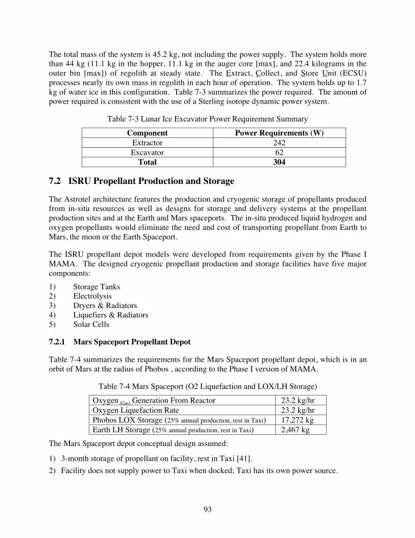
93
The total mass of the system is 45.2 kg, not including the power supply. The system holds morethan 44 kg (11.1 kg in the hopper, 11.1 kg in the auger core [max], and 22.4 kilograms in theouter bin [max]) of regolith at steady state. The Extract, Collect, and Store Unit (ECSU)processes nearly its own mass in regolith in each hour of operation. The system holds up to 1.7kg of water ice in this configuration. Table 7-3 summarizes the power required. The amount ofpower required is consistent with the use of a Sterling isotope dynamic power system.
Table 7-3 Lunar Ice Excavator Power Requirement Summary
Component Power Requirements (W)Extractor 242Excavator 62
Total 304
7.2 ISRU Propellant Production and Storage
The Astrotel architecture features the production and cryogenic storage of propellants producedfrom in-situ resources as well as designs for storage and delivery systems at the propellantproduction sites and at the Earth and Mars spaceports. The in-situ produced liquid hydrogen andoxygen propellants would eliminate the need and cost of transporting propellant from Earth toMars, the moon or the Earth Spaceport.
The ISRU propellant depot models were developed from requirements given by the Phase IMAMA. The designed cryogenic propellant production and storage facilities have five majorcomponents:
1) Storage Tanks2) Electrolysis3) Dryers & Radiators4) Liquefiers & Radiators5) Solar Cells
7.2.1 Mars Spaceport Propellant Depot
Table 7-4 summarizes the requirements for the Mars Spaceport propellant depot, which is in anorbit of Mars at the radius of Phobos , according to the Phase I version of MAMA.
Table 7-4 Mars Spaceport (O2 Liquefaction and LOX/LH Storage)
Oxygen (Gas) Generation From Reactor 23.2 kg/hrOxygen Liquefaction Rate 23.2 kg/hrPhobos LOX Storage (25% annual production, rest in Taxi) 17,272 kgEarth LH Storage (25% annual production, rest in Taxi) 2,467 kg
The Mars Spaceport depot conceptual design assumed:
1) 3-month storage of propellant on facility, rest in Taxi [41].
2) Facility does not supply power to Taxi when docked; Taxi has its own power source.

94
3) Facility keeps liquid hydrogen from Earth liquefied, and takes in oxygen gas from Phobos’surface and liquefies & stores it. Liquefaction of oxygen in orbit allows for a possible 100%duty cycle. (No Dryers necessary)
4) Oxygen gas delivered daily to facility, which operates at 100% duty cycle [41].
5) Linear proportioning of capacities, masses, sizes, power, and capabilities from other systemsusing similar equipment [1, 41].
Figure 7-7: Mars Spaceport Propellant Depot Flow Block Diagram.
Figure 7-8: Mars Spaceport Propellant Depot Rendered 3D Solid Model.
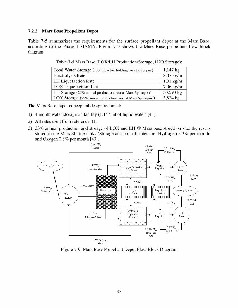
95
7.2.2 Mars Base Propellant Depot
Table 7-5 summarizes the requirements for the surface propellant depot at the Mars Base,according to the Phase I MAMA. Figure 7-9 shows the Mars Base propellant flow blockdiagram.
Table 7-5 Mars Base (LOX/LH Production/Storage, H2O Storage):
Total Water Storage (From reactor, holding for electrolysis) 1,147 kgElectrolysis Rate 8.07 kg/hrLH Liquefaction Rate 1.01 kg/hrLOX Liquefaction Rate 7.06 kg/hrLH Storage (25% annual production, rest at Mars Spaceport) 30,593 kgLOX Storage (25% annual production, rest at Mars Spaceport) 3,824 kg
The Mars Base depot conceptual design assumed:
1) 4 month water storage on facility (1.147 mt of liquid water) [41].
2) All rates used from reference 41.
3) 33% annual production and storage of LOX and LH @ Mars base stored on site, the rest isstored in the Mars Shuttle tanks (Storage and boil-off rates are: Hydrogen 3.3% per month,and Oxygen 0.8% per month [43].
Figure 7-9: Mars Base Propellant Depot Flow Block Diagram.
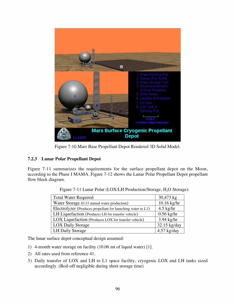
96
Figure 7-10 Mars Base Propellant Depot Rendered 3D Solid Model.
7.2.3 Lunar Polar Propellant Depot
Figure 7-11 summarizes the requirements for the surface propellant depot on the Moon,according to the Phase I MAMA. Figure 7-12 shows the Lunar Polar Propellant Depot propellantflow block diagram.
Figure 7-11 Lunar Polar (LOX/LH Production/Storage, H2O Storage):
Total Water Required 30,473 kgWater Storage (0.33 annual water production) 10.16 kg/hrElectrolyzer (Produces propellant for launching water to L1) 4.5 kg/hrLH Liquefaction (Produces LH for transfer vehicle) 0.56 kg/hrLOX Liquefaction (Produces LOX for transfer vehicle) 3.94 kg/hrLOX Daily Storage 32.15 kg/dayLH Daily Storage 4.57 kg/day
The lunar surface depot conceptual design assumed:
1) 4-month water storage on facility (10.06 mt of liquid water) [1].
2) All rates used from reference 41.
3) Daily transfer of LOX and LH to L1 space facility, cryogenic LOX and LH tanks sizedaccordingly. (Boil-off negligible during short storage time)

97
Figure 7-12 Lunar Polar Propellant Depot Flow Block Diagram.
Figure 7-13 Lunar Polar Propellant Depot Rendered 3D Solid Model.

98
7.2.4 Earth Spaceport Propellant Depot
Table 7-6 summarizes the requirements for the orbital propellant depot at lunar orbit radiusaccording to the Phase I MAMA. Note, that in the current Phase II plan the Earth Spaceport is inan orbit at lunar radius instead of at L1. Figure 7-14 shows the Earth Spaceport Propellant Depotpropellant flow block diagram.
Table 7-6 Earth Spaceport (LOX/LH Production/Storage, H2O Storage):
Total Water Storage (3 month lunar water supply) 3,818 kgElectrolysis Rate 1.59 kg/hrLH Liquefaction Rate 0.18 kg/hrLOX Liquefaction Rate 1.42 kg/hrLH Storage (3 month storage, rest in Taxi) 387 kgLOX Storage (3 month storage, rest in Taxi) 3,099 kg
The following assumptions were made during the Earth Spaceport depot conceptual design:
1) 3 month water storage on facility, rest in Taxi (3.818 mt of liquid water) [41].
2) All rates used from reference 41.
3) Assume 100% duty cycle on solar arrays.
Figure 7-14 Earth Spaceport Propellant Depot Flow Block Diagram.

99
Figure 7-15 Earth Spaceport Propellant Depot Rendered 3D Solid Model.
7.3 Recommendations for Future Robotic Exploration for ISRU
As stated previously, little is known about the surface of Phobos and several conflicting theoriesexist about the physical and chemical composition of Phobos regolith. We recommend sciencestudies about Phobos in the future to measure:
1) Surface regolith and underlying base material properties, including size composition,compaction, friction angle, composition by depth, thermal, etc.
2) Location of surface and subsurface anomalies, such as mineral concentrations, caverns, andgravitational attraction.
3) The surface environment including temperature, wind, dust, radiation, and micro-meteorimpact

100
8 Flight Systems Development
8.1 Introduction
In this section we describe common technologies that are used in all architectures, the commonsystem elements used in several vehicles, and the detailed flight systems designs.
8.2 Common Transportation Architecture Technologies
Several common technologies exist that are used throughout the architecture, namely,propulsion, power and radiation protection technology.
8.2.1 Propulsion Systems
8.2.1.1 Chemical (LOX/LH) Propulsion
Many options exist for the design basis for the LOX/LH engines used in the Mars Transportationarchitecture. For the purpose of the Phase I study, however, a 7:1 mixture ratio LOX/LH, Pratt &Whitney (P&W) RL-series propulsion system has been assumed. The RL10 engine is anExpander Power Cycle engine, meaning that the Hydrogen is circulated through the nozzle topre-heat it and provide high-pressure gas power for the fuel and oxidizer turbo-pumps. Fortypical LOX/LH engines the mixture ratio is 5 or 6:1. Today’s Space Shuttle main engines areset at a 6:1 mixture ratio while the P&W RL10, used on Centaur, actually varies its mixture ratiobetween 5:1 and 6:1 in flight to ensure near simultaneous fuel and oxidizer depletion. Theimplications of the 7:1 mixture ratio are 1) reduced the hydrogen volume required and thusreduced vehicle size and 2) somewhat reduced thrust level. Nominal parameters of the RL10B-2engine at 5-6:1 mixture ratios are a thrust of 110.1 kN (24,750 lbsf), Isp of 464 s, propellant burnrate of 24.4 kg/s and a mass of about 277 kg. Thrust and burn rate of this engine operating at a7:1 mixture ratio is estimated at 66.7 kN (15,000 lbsf) and 14.8 kg/s. A nice feature of this engineis its extendable nozzle, which enables it to fit in a volume about half of its deployed state (itslength goes from about 4.1 m to 2.1 m long). Figure 8-1 is a drawing of the RL10B-2 enginewith nozzle retracted.
A higher thrust engine is desirable for the Mars transportation architecture. P&W is nowdeveloping an advanced RL-series engine called an RL60, having 60,000 lbs. of thrust, roughlythree times higher than the RL10. In addition, the current RL60 design driver is missions to GEOthat require 2 engine restarts for a total of only 3 burns and a total engine life of only 700 s.Maximum engine gimbaling capability of ±5° is expected. This engine has an Isp of 459 s at amixture ratio of 7:1. For the purpose of the Mars transportation architecture, a higher thrustengine than the existing RL10 is desired in order to reduce finite burn and gravity losses due tothe large, long delta-V burns at Mars. The RL60 engine is about the same form factor as theRL10, the increase performance coming from running the chamber pressure about three timeshigher.

101
Considerable engine technology development may be required to enable several hours of reliableoperation in remote locations, however, the Space Shuttle main engines were originally designedto operate for about 8 hours over about 55 starts without major overhaul. The specific wearissues relate generally to rotating machinery items such as bearings, seals, etc. For a multi-yearmission requirement, there are additional considerations that need to be addressed (e.g. slowflowing of static seals, slow degradation of material properties specifically used in the enginedue to factors such as radiation).
Figure 8-1 Pratt & Whitney RL10B-2 Engine
For the purpose of this study we have assumed a LOX/LH engine based on the new RL60 enginebut with a de-rating to account for the higher mixture ratio, the projected longer burn, and longerlife requirements. The assumed rocket engine for the architecture has the followingcharacteristics:
Table 8-1 LOX/LH Engine Characteristics
Parameter ValueMixture Ratio 7:1Thrust 266.9 kN (60,000 lbsf)Specific Impulse 460 sPropellant Burn Rate 59.2 kg/sEngine Mass 500 kg

102
8.2.1.2 Solar-Powered Ion Propulsion
After more than 40 years of development by NASA, solar-powered ion propulsion systems (IPS)are now operational. JPL’s Deep Space 1 (DS1), which used IPS, launched in October of 1998.DS1’s IPS consisted of a throttling, single 30-cm diameter, 2.5 kW input Xenon ion thrusteroperating at an exhaust velocity of about 30.4 km/s (Isp of 3100 s) capable of thrust levels fromabout 21-92 mN. The following figure illustrates the key components of the DS1 IPS.
Solar Array
PropellantStorage
Gimbal
PowerConditioning
Exhaust
S/CC&D
H
PropellantDistribution
andControl
DigitalInterface &Control Unit
Note: Structural and ThermalHardware Not Shown
Thruster
Solar Array
Figure 8-2 Simplified Block Diagram of an IPS (courtesy J. Brophy, JPL)
An ion propulsion system (IPS) converts solar generated electrical energy to momentum ofpositively charged molecules or ions (since the 1980s noble gases, like Xenon, have replacedMercury for ion thrusters). This conversion is accomplished by first ionizing suitable atoms byelectron bombardment and then accelerating them in the desired direction by using twoelectrically charged grids. The magnitude of the applied voltage and the charge-to-mass ratio ofthe ions determines the exhaust velocity. The momentum of these ions reacts against a spacecraftpropelling it in the opposite direction. An IPS can be extremely efficient if sufficient solar poweris available and a long time is allowed for making velocity changes. The reason for thisefficiency can be seen in the “rocket equation.” The rocket equation is, ∆V=Ve*ln(mi/mf), whereVe is the exhaust velocity of the thruster and mi and mf are the initial and final mass of thespacecraft. In the rocket equation the delta-V is directly proportional to the exhaust velocity ofthe rocket engine. If the initial spacecraft mass is only 10% greater than the final mass,(meaning mi=1.1mf), the delta-V capability of the DS1 IPS is nearly 3 km/s. Given the same finalmass but a LOX/LH engine with a Ve of 4.5 km/s, more than 90% of the final mass is required toachieve the same delta-V (mi=1.9mf). It is this efficiency that makes an IPS very attractive formaking the occasional course corrections required of the Astrotels, providing station-keepingforces for the Spaceports and providing the primary motive force behind the interplanetary cargofreighters delivering consumables, propellants and refurbishment hardware to Spaceports andAstrotels.
8.2.1.2.1 Status and Plans
The DS1 IPS is obviously a resounding success but considerable technology advance is stillneeded by the Mars transportation systems under study. Fortunately, there is ongoing NASA

103
research into IPS technology that is moving in the proper direction. The following figureillustrates one possible evolution of IPS technology development.
Today The Future
Mars Cargo Freighter IPSSegmented Ion Thruster
100 cm dia grid sets~1 MW inputIsp = 10,000 s
~4 kg/kW Specific Mass
NASA GRC40 cm dia5 kW inputIsp = 3800 s
JPL30 cm dia
3.4 kW inputIsp = 3800 s
DS130 cm dia
2.5 kW inputIsp = 3100 s17.2 kg/kW
Specific Mass
Astrotel IPS50 cm dia
148 kW inputIsp = 5000 s
3.8 kg/kW Specific Mass
Figure 8-3 Example Evolution of IPS Technology
JPL has worked on a modest upgrade of the DS1 thruster which increases the input power to thePower Processing Unit (PPU) by about 35% to 3.4 kW at the same time increasing the specificimpulse by about 23% to 3800 s. This thruster design is slated for several possible missionsincluding a comet nucleus sample return. NASA Glenn Research Center is working on a 40-cmdiameter thruster that also would operate at a specific impulse of 3800 s.
Conventional single engine designs are limited as higher powers are processed and exhaustvelocities are increased because of the difficulty in making the accelerator system (thruster span-to-gap ratios, accelerating voltage constraints, and current handling capability). In order tomaintain constant power density across a thruster the grid separation must remain constant.Current thrusters have an engine-span-to-grid-gap ratio of about 500 (a 30-cm diameter enginecould have its high voltage grids separated by a gap of only 0.6 mm depending on voltageacross). As the desire to process more power grows, the engine diameter grows. Assumingpractical limits to the electric field between the grids the span-to-gap ratio can eventually growbeyond the state-of-the-art.
Because of the need to process much larger levels of power over larger area thrusters andbecause of the practical limits to span-to-gap ratios, multiple grid sets are attractive. Multiple

104
grid sets, along with their smaller individual ion source components, electrically connect severalgrid sets together so that they simulate a larger diameter thruster yet still retaining the desiredspan-to-gap ratio for each engine segment. Additionally, only one neutralizer is required for themultiple grid set and the smaller individual ion source chambers reduce complexity and otherplasma problems. Multiple grid sets per engine can significantly increase the beam current perengine. Such Segmented Ion Thruster (SIT) designs include individual propellant ionizationchambers for each engine segment and only one neutralizer for the set of two or more thrusters.Multiple aperture grid ion propulsion is assumed for the Astrotel and Cargo Freighter propulsionsystems because of the advantages discussed above.
8.2.1.2.2 Astrotel IPS
There are several system options for the Astrotel IPS depending on technology advanceincluding the upgrade of DS1 engine technology or designing a new 8-set SIT.
8.2.1.2.2.1 Upgrade DS1 Engine Technology
Upgrade of DS1 single engine technology from a 30-cm diameter, 2.5 kW, 3100 s specificimpulse, and 19.2 kg/kW specific mass system to a 50-cm diameter, 17.2 kW input, 5000 sspecific impulse, and 3.8 kg/kW specific mass system. This appears to be a modest improvementin technology, especially since 30-cm diameter engines have already been run at 20 kW inputpower about 15 years ago, though not with the lifetime capability required for the Astrotelsystem. Given the requirements of the Astrotel IPS, J. Brophy at JPL generated a model of thisengine. The model inputs and resultant performance are presented in the following tables.
Table 8-2 Astrotel Ion Engine Performance Input Data
Parameter Value
Engine Type RING CUSPPropellant (AMU) 131.3Beam Diameter (cm) 50Specific Impuse (s) 5000Max. Span-to-Gap Ratio 500Minimum Grid Gap (mm) 0.6Max. E-Field (V/mm) 2600Max. Disch. Current (A) 100Max. Beam Current (A) 6.75Maximum R-Ratio 0.9Minimum R-Ratio 0.55Perveance Coef. Xe x10E9 2.48Perveance Exponent 1.5Screen Grid Tranparency 0.75Beam Flatness Parameter 0.6Divergence Thrust Loss 0.98Double Ion Ratio 0.1Discharge Voltage (V) 28Disch. Chmbr Prop. Eff. 0.92Discharge Loss (eV/ion) 180Keeper Current (A) 0Keeper Voltage (V) 4Coupling Voltage (V) 15Neut. Keeper Current (A) 2Neut. Keeper Voltage (V) 15Neut. Flow Fraction 0.05
ION ENGINE PERFORMANCE INPUT DATA

105
Table 8-3 Model-Estimated Performance of Astrotel Ion Engine
Parameter Value
Thrust (N) 0.515Engine Input Power (kW) 17.23Total Engine Efficiency 0.733Thrust-to-Power Ratio (mM/kW) 29.91Beam Voltage (V) 2353Total Voltage (V) 2615Net-to-Total Voltage Ratio 0.9Beam Current (A) 6.75Discharge Current (A) 43.38Grid Gap (mm) 1.006Actual Span-to-Gap Ratio 497.2Screen Hole Diameter (mm) 3.35Effective Acceleration Length (mm) 1.95Maximum Beam Current Density (mA/cm2) 5.73Average Beam Current Density (mA/cm2) 3.44Double Ion Thrust Loss Factor 0.97Total Propellant Efficiency 0.87Total Propellant Flow Rate (g/s) 0.01052
CALCULATED ION ENGINE PERFOMANCE
The overall ion propulsion system mass breakdown based on the upgrade of the DS1 IPS isshown in the following table.
Table 8-4 Astrotel IPS Mass Breakdown
Item QTYUnit
Mass, kg
Total Mass,
kgComments
Engine 8 18.40 147.2PPU 8 36.40 291DCIU 2 3.00 6 1 required plus one spareRegulator 2 0 .45 0.90Service Valve - HP 1 0.01 0.01Service Valve - LP 1 7 0.01 0.17Pressure Transducer 2 0.25 0.50Latch Valve - HP 2 0.10 0.20 8.71Latch Valve - LP 8 0.10 0.80Fi l te r 1 0.13 0.13Var. Reg. With Flow Meter 2 4 0.15 3.60Tubing 1 2.00 2.00Fittings 1 0.40 0.40Gimbal 8 5.52 44.16 One for each thrusterMisc. Thermal (5% of dry mass) 1 24.86 24.86Cabling (5% of dry mass) 1 24.86 24.86Structure (4% of dry mass) 1 21.88 21.88Total 569
Conventional Approach with Redundancy -- XFS
The summary assumptions and description for this option for the Astrotel IPS is shown in thefollowing table.

106
Table 8-5 Summary Assumptions and Description for Astrotel IPS
Assumptions1 150 kW System Input Power2 2800 kg total propellant processed3 Xenon propellant4 Gridded ion engines5 Specific Impulse = 5000 s
PROPULSION MODULE SUMMARY NotesNumber of Engines 8Number of Operating Engines 8IPS Thrust (N) 4.12IPS Input Power (kW) 148.2Engine Input Power (kW) 17.23Engine Thrust (N) 0.515Engine Unit Mass (kg) 18.4Gimbal Mass (kg) 5.5Propulsion Module Cabling Mass (kg) 24.9Xenon Feed System (kg) 8.71Xenon Tank Mass (kg) 51.3 Assumes a tank sized for 1027 kg of xenonPropulsion Module Structure (kg) 21.88Propulsion Module Dry Mass (kg) 272 Not including PPUsPropulsion Module Specific Mass (kg/kW) 1.8
POWER PROCESSING SUBSYSTEM SUMMARYNumber of PPUs 8PPU Specific Mass (kg/kW) 1.96PPU Unit Mass (kg) 36.4PPU Efficiency 0.93Radiator Area per PPU (m2) 3.1Total PPU Mass (kg) 291Total PPU Radiator Area (m2) 24.8 Radiator mass not includedNumber of DCIUs 2DCIU Unit Mass (kg) 3
Total IPS Mass (kg) 569Total IPS Specific Mass (kg/kW) 3.84 Note the total NSTAR IPS specific mass is 19.2 kg/kW
The Xenon tank was sized for about one third the Xenon required over a 15-year cycle ofoperations. Note that the system specific mass is 3.8 kg/kW, a factor of over 4-timesimprovement over the current DS1 IPS. Such an improvement is projected to be possible in the2010 timeframe.
8.2.1.2.2.2 Alternative Astrotel IPS
Instead of having eight individual engines, an eight-set segmented ion thruster (SIT) could beemployed. This approach might offer some simplification and hardware part reduction sincethere would only be one neutralizer and one high voltage power supply.
If the 100-cm diameter grid set operating at 125 kW input could be developed, a throttled 2 grid-set SIT could be employed for the Astrotel IPS and an eight grid-set SIT could be used for theMars Cargo Freighter.
8.2.1.2.3 Cargo Freighter IPS
For the low thrust trajectory analysis and the system definition of the Astrotel and Mars CargoFreighter vehicles we assumed a propulsion specific mass of 4 kg/kW, consistent with theestimated performance in 2010. In addition, we assume a power system specific mass of 4kg/kW, for a total power and propulsion system specific mass of about 8 kg/kW. The Astroteland Mars Cargo Freighter input power requirements are expected to be much larger than theAstrotel requirements between 300-900 kW. This large size will likely require SIT

107
configurations. For the purpose of the low thrust trajectory analysis, a specific impulse of only5000 s was assumed. If a specific impulse of 10,000 s becomes a reality for a SIT system of thissize, significant improvement in performance will occur.
8.2.1.3 References
1. Popp, M., Bullock, J. R., Santiago, J. R., Development Status of the Pratt & Whitney RL60Upper Stage Engine, AIAA-2002-3587, presented at 36th AIAA/ASME/SAE/ASEE JointPropulsion Conference, Indianapolis, IN, July 7-10, 2002.
2. Brophy, J., “Near-Term, 100 kW-Class Ion Engines”, AIAA Paper # 91-3566,AIAA/NASA/OAI Conference on Advanced SEI Technologies, Cleveland, OH, September1991.
3. Brophy, J., “Ion Propulsion System Design for the Comet Nucleus Sample Return Mission”,AIAA Paper # 2000-3414, 36th AIAA/ASME/SAE/ASEE Joint Propulsion Conference andExhibit, Huntsville, AL, July 2000.
4. Polk, J., et. al., “In-Flight Performance of the NSTAR Ion Propulsion System on the DeepSpace One Mission”, IEEE paper, 2000.
8.2.2 Power Systems
Two power conversion system choices were examined, namely nuclear and photovoltaic arrays.Factors considered in power generation technology selection are life cycle cost, specific power(power generated divided by generation and storage mass), modularity, and safety (spaceoperations and manufacturing). Because solar photovoltaic power generation appeared veryattractive due to the projected very low cost and mass, it was selected for the baselinearchitecture. This baseline selection was tested in Phase II with respect to life-cycle cost and theresults are displayed in Section 9. Energy storage options are also discussed.
8.2.2.1 Solar Photovoltaic Power Generation
There are two very different photovoltaic powered missions involved in this report – deep spaceand planetary or satellite surface operation. The near term technology applicable to both thesemissions will be discussed first and then projected to technologies likely to be available in 2010.For the projection of solar array technology to 2010, cells are expected to have improvedefficiency and structures and optical systems should become lighter.
8.2.2.1.1 Deep Space Solar Arrays
Deep space missions are those which take the spacecraft out of Earth orbit to orbits betweenEarth and the Moon, the L1 point and past Mars. Since Mars is not too distant from the sun, allof these missions can be handled with essentially the same power generation system technology.The size of power generation systems for the Mars transportation architecture ranges from about12 kW to nearly 1 MW.

108
8.2.2.1.1.1 Mechanical and Optical Technologies
The near term technology was reviewed with regard to demonstrated performance at least at thesolar array module level, cost and possibility of improvement. Two aspects were studiedincluding lightweight deployable and concentrator arrays.
Lightweight photovoltaic energy conversion systems, or solar arrays, have been used on mostspace missions. However, very large solar arrays (100 kW) are not common so there is littleexperience applicable to this study. The analysis presented in this section is based uponprojection of past development onto present demonstration technologies. Lightweight,deployable, photovoltaic arrays have been demonstrated for space missions ["AdvancedPhotovoltaic Solar Array Design," TRW Report No. 46810-6004-UT-00, 3 November 1986] andare being incorporated into a number of programs. Dependent upon the technology selected,large (in excess of 2kW), high performance arrays cost about $850/W. Using current costs, a160 kW array, as suggested for the Astrotel, could cost 136 million dollars.
A solar cell concentrator approach, which should reduce array cost, uses fewer of the expensiveelements, i.e. the solar cells. A 15 times concentrator array uses roughly one-twelfth the numberof solar cells. Concentrator arrays have now been space qualified [P. A. Jones et al., “TheSCARLET Light Concentrating Solar Array,” 25th IEEE-PVSC, 1996] on the DS-1 spacecraft.The SCARLET array has achieved over 200 W/m2 areal power density and 45 W/kg specificpower. Figure 8-4 illustrates the SCARLET array in flight.
A combination of lightweight array and concentrator technology is in the demonstration phase[M. J. O’Neill, “The Stretched Lens Ultralight Concentrator Array,” 28th IEEE-PVSC, 2000].The stretched lens array (SLA) has been incorporated into a deployable, flexible-blanket planarspace array concept called Aurora by AEC-ABLE. Figure 8-5 illustrates a stretched lens ArrayPrototype. Figure 8-6 illustrates a deployment concept for the SLA.
Aurora components have already demonstrated a cell efficiency of 30% and a lens efficiency of92%. Operational efficiency at beginning of life (BOL) is expected to be 22% or about 300W/m2 areal power density. This corresponds to a near term expectation of 170 W/kg BOLspecific power at the deployed wing level. The combination of SCARLET and SLA technologypotentially provides a 50% increase in areal power density and almost a 300% increase inspecific power.
Figure 8-4 Picture of SCARLET Array on DS1 Spacecraft (Courtesy ENTECH)

109
Figure 8-5 Stretched Lens Array Module Prototype (Courtesy ENTECH)
Figure 8-6 SLA Deployment Concept (Courtesy ENTECH)
Table 8-6 Aurora Array Performance
Average Cell Efficiency at 8 Suns and Room Temperature (Demonstrated)
30%
Average Cell Efficiency at 80C (GEO Operational Temperature)
26%
Lens Efficiency (Demonstrated) 92%Cell-to-Panel Packing Factor 95%Wiring/Mismatch Factor 95%
Operational Array Efficiency (Product of Last Four Values)
22%
Areal Power (W/sq.m.) 296Areal Mass (kg/sq.m.) 1.74Specific Power (W/kg) 170
Beginning of Life (BOL) Performance Parameters
8.2.2.1.2 Solar Cell Technology
JX Crystals projects 32-35% cell efficiency in 10 years. This is a conservative estimate sincethey have already achieved 30% with non-optimized cells [L. Fraas et al., “30% EfficientInGaP/GaAs/GaSb Cell-Interconnected-Circuits for Line-Focus Concentrator Arrays,” 28th IEE-PVSC, 2000]. The following figure shows a typical stacked cell set. The top picture is acompleted InGaP/GaAs/GaSb circuit, the middle is a circuit with GaSb IR cells and the bottom isthe substrate with metal traces. These overlay each other to form the integrated cell.
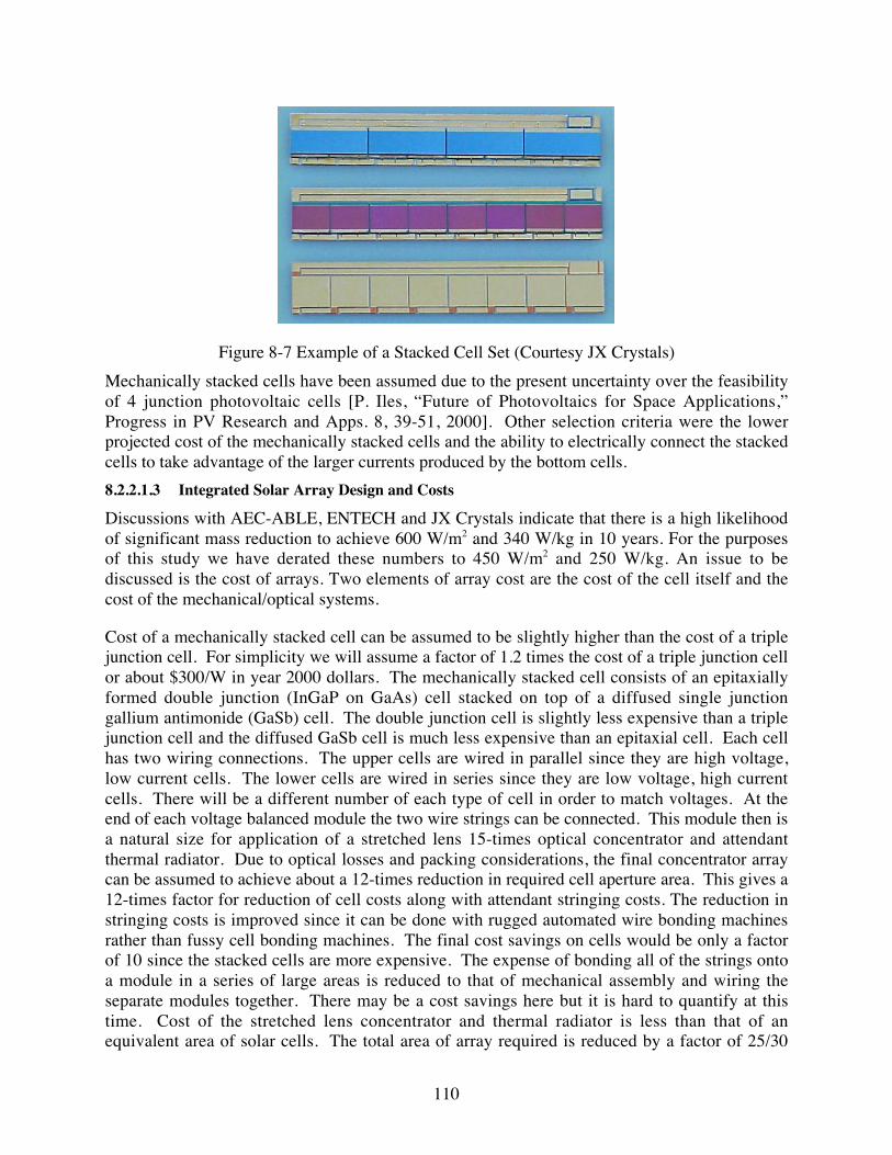
110
Figure 8-7 Example of a Stacked Cell Set (Courtesy JX Crystals)
Mechanically stacked cells have been assumed due to the present uncertainty over the feasibilityof 4 junction photovoltaic cells [P. Iles, “Future of Photovoltaics for Space Applications,”Progress in PV Research and Apps. 8, 39-51, 2000]. Other selection criteria were the lowerprojected cost of the mechanically stacked cells and the ability to electrically connect the stackedcells to take advantage of the larger currents produced by the bottom cells.
8.2.2.1.3 Integrated Solar Array Design and Costs
Discussions with AEC-ABLE, ENTECH and JX Crystals indicate that there is a high likelihoodof significant mass reduction to achieve 600 W/m2 and 340 W/kg in 10 years. For the purposesof this study we have derated these numbers to 450 W/m2 and 250 W/kg. An issue to bediscussed is the cost of arrays. Two elements of array cost are the cost of the cell itself and thecost of the mechanical/optical systems.
Cost of a mechanically stacked cell can be assumed to be slightly higher than the cost of a triplejunction cell. For simplicity we will assume a factor of 1.2 times the cost of a triple junction cellor about $300/W in year 2000 dollars. The mechanically stacked cell consists of an epitaxiallyformed double junction (InGaP on GaAs) cell stacked on top of a diffused single junctiongallium antimonide (GaSb) cell. The double junction cell is slightly less expensive than a triplejunction cell and the diffused GaSb cell is much less expensive than an epitaxial cell. Each cellhas two wiring connections. The upper cells are wired in parallel since they are high voltage,low current cells. The lower cells are wired in series since they are low voltage, high currentcells. There will be a different number of each type of cell in order to match voltages. At theend of each voltage balanced module the two wire strings can be connected. This module then isa natural size for application of a stretched lens 15-times optical concentrator and attendantthermal radiator. Due to optical losses and packing considerations, the final concentrator arraycan be assumed to achieve about a 12-times reduction in required cell aperture area. This gives a12-times factor for reduction of cell costs along with attendant stringing costs. The reduction instringing costs is improved since it can be done with rugged automated wire bonding machinesrather than fussy cell bonding machines. The final cost savings on cells would be only a factorof 10 since the stacked cells are more expensive. The expense of bonding all of the strings ontoa module in a series of large areas is reduced to that of mechanical assembly and wiring theseparate modules together. There may be a cost savings here but it is hard to quantify at thistime. Cost of the stretched lens concentrator and thermal radiator is less than that of anequivalent area of solar cells. The total area of array required is reduced by a factor of 25/30

111
which is the ratio of the operating efficiencies at GEO of a triple junction cell to that of thestacked cell. The net result of all of these changes is to produce a final cost per watt of anAurora type space array of about $700/W. Additional savings might be realized from the largesize of the array but this can not be easily quantified especially 10 years into the future.
8.2.2.1.4 Planetary Surface Solar Arrays
Surface operations requiring solar array power are contemplated on the Moon, Mars, andPhobos. These locations can be serviced with essentially the same technology – at least as a firstapproximation. The types of solar arrays that can be placed on a planetary surface include a) arigid structural space or terrestrial solar array modules, which can be oriented at a fixed angle orpointed in one or two axes to track the sun or b) a low-cost, lightweight, flexible, thin-film solararray that can be laid out on the surface over large areas. We have selected the lightweight, low-cost approach.
An additional consideration for surface array operation on natural satellites or planets might bethe inclusion of a electrostatic or mechanical robotic dust removal system or “Dustbot.”
8.2.2.1.4.1 Near Term Technology
Planetary (Mars) and satellite (Moon and Phobos) surfaces provide a fixed surface for mountinga photovoltaic array and thus an opportunity to reduce mass by eliminating most of the structure.Due to planet rotation, the solar angle on the array changes continuously and is almost nevernormal to the surface of the cells. Thus the size of the array must account for the varying solarangles. In addition, operations (including ISRU), duty cycles and capacities must be designed torespond to the varying solar energy input. At the Lunar poles the Sun is almost always at thehorizon. A suitable location for a large surface mounted array must be found that will allowsufficient solar illumination. The Lunar South Pole has a mountainous region where an arraycould be positioned at an angle of 40° to the horizontal. Significant oblique solar illuminationwill require several times the array area as opposed to when the sun is normal to the array.
A United Solar press release on their web site [http://www.ovonic.com/unitedsolar/uninews]claims that their thin-film triple-junction amorphous silicon (see following figure) modules onthe MIR space station have a specific power greater than 500 W/kg (2 kg/kW).
Figure 8-8 Triple Junction a-Si Cell

112
The United Solar modules were a special run with the cells deposited on a thin (between 0.5 and1 mil thick) stainless steel substrate rather than the standard 5mil substrate. Neither areal poweror conversion efficiency is noted in the press release. If the stainless steel substrate were 0.8 milthick and no other mass is assumed then the conversion efficiency can be calculated at 5.9%.This low efficiency imposes a large supporting structure mass penalty on a spacecraft but not ona fixed ground installation.
Iowa Thin Film Technologies (ITFT) is producing single-junction amorphous silicon modules ona 5-mil thick polymer (Kapton) substrate. The ITFT modules operate at 5% efficiency and havebeen made on special order on 2-mil thick Kapton. These special modules had a specific powerof about 650 W/kg (1.54 kg/kW).
8.2.2.1.5 2010 Technology
Thin film photovoltaic cell systems of amorphous silicon, cadmium telluride, copper indiumdiselenide (CIS), and copper indium gallium diselenide (CIGS) are all being developed forapplication on flexible substrates like thin polymer films. One near-term technology – triplejunction amorphous silicon solar cells - has achieved 10% efficiency for long lifetime and theirfuture is very promising. When compared with conventional crystalline solar cells, thin filmsolar cells have several advantages for planet surface operations application. Advantages includephysical flexibility afforded by their thin-film construction, ability to be fabricated intomonolithic cell strings and good resistance to radiation.
NASA has studied advanced thin-film, flexible solar array systems for Lunar and Mars surfaceapplications utilizing amorphous silicon solar cells for flexible solar array blankets [Colozza, A.J., Design and Optimization of a Self-deploying PV Tent Array, NASA CR 187119, June 1991].The areal density of these planetary solar array systems was stated to be about 20 g/m2. Thisrepresents an array using a polymer substrate less than 1-mil (25 um) in thickness and has littleor no allowance for wiring and probably no allowance for any deployment or attachmenthardware. A more realistic estimate would be about 4 times higher mass or 80 g/m2 for a 2-milsubstrate, wiring and minimal hardware. CIGS technology is very likely to produce AM0 (airmass zero – space) cells on polymer substrates with about 14% conversion efficiency in 10 years.Using the 80 g/m2 and 14% figures gives a calculated specific power of 2400 W/kg(0.42 kg/kW). This value needs to be derated to account for packing factor and operatingtemperature. Using estimates of 0.9 for packing factor and 0.9 for temperature derating yields amore reasonable specific power of 1920 W/kg (or about 0.52 kg/kW).
A design value of 1 kg/kW is appropriate for this study, which includes stakes, tie downs, roboticdusters and other necessary surface deployment and maintenance hardware. A much moreconservative specific power of 250 W/kg (4 kg/kW) has been assumed in the calculations ofsurface power mass requirements.
8.2.2.2 Nuclear Power Generation
Two types of nuclear reactor systems were evaluated for the Astrotel architectures, namely,surface systems, for use at the Mars Base and at resource utilization sites, and space systems toprovide power for the Astrotel itself and the cargo vehicles that utilize electric propulsionsystems. Figure 8-9 displays the mass and cost of space reactors as a function of power level.

113
Space Nuclear Systems
0
5000
10000
15000
20000
25000
30000
35000
0 500 1000 1500 2000 2500 3000
Power Level, kW
Sys
tem
Mas
s, k
g
1000
2000
3000
4000
5000
6000
7000
8000
Dev
elo
pm
ent
Co
st, $
M
Mass
Cost
© 2003 Global AeroSpace Corporation
Figure 8-9 Space Nuclear Reactor System Mass and Cost as a Function of Power Level
The primary reference for these data comes from a paper entitled “Liquid Metal Cooled Reactorfor Space Power” by Weitzberg presented at Space Technology & Applications InternationalForum (STAIF) 2003. The scaling is not reliable for power levels below about 100 kW. Figure8-10 displays similar information for surface reactors.
Planet Surface Nuclear Systems
0
5000
10000
15000
20000
25000
30000
0 100 200 300 400 500 600 700 800 900 1000
Power Level, kW
Sys
tem
Mas
s, k
g
600
1100
1600
2100
2600
3100
3600
Dev
elo
pm
ent
Co
st, $
M
Mass
Cost
© 2003 Global AeroSpace Corporation
Figure 8-10 Surface Nuclear Reactor System Mass and Cost as a Function of Power Level
The surface scaling comes primarily from a paper entitled “Design Concept for a NuclearReactor-Powered Mars Rover” by Elliot, Lipinski, and Poston also presented at STAIF 2003.

114
8.2.2.3 Energy Storage
Energy storage requirements are in two categories, namely the need for power for small, non-solar-powered spacecraft like Taxis and power storage for solar-powered space and surfacesystems during nighttime or eclipse operation. Since photovoltaic energy conversion requiressunlight, the “fixed” base solar-powered space (Astrotels and Spaceports) and surface (resourcesplants) systems must have an energy storage system to handle nighttime or eclipse power needs.In most surface system cases, limiting major operations to the daytime hours minimizesnighttime energy requirements. Nighttime requirements are generally keep-alive power in orderto keep electronics from failing at cold temperatures. In the case of power for small spacecraftlike Taxis, small, high energy density energy storage systems are needed. In addition, they mustbe either rechargeable or refillable at a transportation node.
8.2.2.3.1 Energy Storage Options
The types of energy storage that can produce electricity directly are fuel cells, ultra capacitors,and batteries. For larger systems flywheels sometime can also become competitive in energydensity with some types of batteries. Flywheel storage has not been widely used and has aserious limitation with friction losses when the storage period is long term. High capacitycapacitors still do not have an adequate power density for space use. This reduces the energystorage options to fuel cells and secondary batteries.
8.2.2.3.1.1 Fuel Cells
Fuel cells using hydrogen and oxygen are used in the Space Shuttle and are a proven technology.Standard fuel cell energy conversion systems require pressurized tanks for both fuel andoxidizer. Estimated specific power for a fuel cell is 700-1000 W-hr/kg [Nesmith, W., DOE HQ,Personal communications, October 1997]. New technology options include a regenerative fuelcell that contains both a fuel cell and an electrolysis capability in the same unit. Regenerativefuel cells for energy storage have been investigated for application to solar-powered aircraft atenergy densities about 400 W-hr/kg including tanks though only about 250 W-hr/kg hascurrently been demonstrated. For a non-regenerative system, oxygen and hydrogen for fuel celloperation can be generated and stored at a surface based facility to refuel the cells periodically.Space energy storage might benefit from the use of regenerative fuel cells where the hydrogenand oxygen are reacted to form water when power is needed. Later when surplus power isavailable the water can be broken down by electrolysis into hydrogen and oxygen.
8.2.2.3.1.2 Secondary Batteries
The types of secondary batteries that should be considered are nickel-hydrogen, nickel-metalhydride, lithium-ion, and lithium-ion polymer. These presently have the approximate energydensities (W-hr/kg) shown (cell size and packaging dependant):
Table 8-7 Battery energy densities, W-hr/kg
Nickel-hydrogen 60Nickel-metal hydride 80Lithium-ion 100Lithium-ion polymer 130
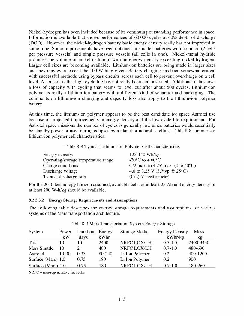
115
Nickel-hydrogen has been included because of its continuing outstanding performance in space.Information is available that shows performances of 60,000 cycles at 60% depth-of discharge(DOD). However, the nickel-hydrogen battery basic energy density really has not improved insome time. Some improvements have been obtained in smaller batteries with common (2 cellsper pressure vessels) and single pressure vessels (all cells in one). Nickel-metal hydridepromises the volume of nickel-cadmium with an energy density exceeding nickel-hydrogen.Larger cell sizes are becoming available. Lithium-ion batteries are being made in larger sizesand they may even exceed the 100 W-h/kg given. Battery charging has been somewhat criticalwith successful methods using bypass circuits across each cell to prevent overcharge on a celllevel. A concern is that high cycle life has not really been demonstrated. Additional data showsa loss of capacity with cycling that seems to level out after about 500 cycles. Lithium-ionpolymer is really a lithium-ion battery with a different kind of separator and packaging. Thecomments on lithium-ion charging and capacity loss also apply to the lithium-ion polymerbattery.
At this time, the lithium-ion polymer appears to be the best candidate for space Astrotel usebecause of projected improvements in energy density and the low cycle life requirement. ForAstrotel space missions the number of cycles is generally low since batteries would essentiallybe standby power or used during eclipses by a planet or natural satellite. Table 8-8 summarizeslithium-ion polymer cell characteristics.
Table 8-8 Typical Lithium-Ion Polymer Cell Characteristics
Energy density: 125-140 Wh/kgOperating/storage temperature range -20°C to + 60°CCharge conditions C/2 max. to 4.2V max. (0 to 40°C)Discharge voltage 4.0 to 3.25 V (3.7typ @ 25°C)Typical discharge rate (C/2) [C – cell capacity]
For the 2010 technology horizon assumed, available cells of at least 25 Ah and energy density ofat least 200 W-h/kg should be available.
8.2.2.3.2 Energy Storage Requirements and Assumptions
The following table describes the energy storage requirements and assumptions for varioussystems of the Mars transportation architecture.
Table 8-9 Mars Transportation System Energy Storage
System Power Duration Energy Storage Media Energy Density Mass kW days kWhr kWhr/kg kg Taxi 10 10 2400 NRFC LOX/LH 0.7-1.0 2400-3430Mars Shuttle 10 2 480 NRFC LOX/LH 0.7-1.0 480-690Astrotel 10-30 0.33 80-240 Li Ion Polymer 0.2 400-1200Surface (Mars) 1.0 0.75 180 Li Ion Polymer 0.2 900Surface (Mars) 1.0 0.75 180 NRFC LOX/LH 0.7-1.0 180-260 NRFC – non-regenerative fuel cells

116
8.2.3 Radiation Protection
Interplanetary radiation includes high energy Galactic Cosmic Radiation (GCR), which is verydifficult to protect against, and solar flare particle events (SPEs), which consist mostly of high-energy protons. GCR is continuous while SPEs only occur during major solar storms. SPEs canlast from minutes to hours. It is necessary to provide protection against SPEs because thisradiation can be quite harmful and can cause death for unprotected humans. A major SPE, had itoccurred with Apollo astronauts on the moon, would likely have killed them. The effect of GCRis expected to result in a small increased risk of cancer over the crew times usually considered.The following figure describes one model for the shielding required of various materials in orderto reduce cell damage (transformation) by a particular amount for a one year exposure (in NRCreport on Radiation Hazards to Crews of Interplanetary Missions, 1996).
Figure 8-11 Required Shielding of Various Materials
The effect of high Z materials for shielding against radiation is counter-intuitive. Lead shieldingactually increases the dose of damaging radiation as compared to no shielding at all. Thisincrease is due to more particles being generated as the result of collisions in the shieldingmaterial. Very thick layers of lead are required for any protection at all. In discussions withSAIC personnel at JSC, current reference mission planning assumes the use of available waterand water-bearing food stuffs in the transfer vehicle cargo for protection. In the future, there mayalso be consideration of an onion skin approach to shielding materials, which could be addedover time. Substantially shielding of crew sleeping quarters, where crews will spend a significantamount of their time, can significantly reduce the overall GCR dose. Liquid hydrogen is a verygood shielding material for SPEs, a 30-cm thickness reducing the cell damage by an order ofmagnitude below unprotected cells. Of course water is easier to store at room temperature, but itonly reduces cell damage by 50% with the same thickness of shield. It is clear that an SPE stormshelter of some kind will be required on the Astrotel because the protection of the entire vehiclewill likely be prohibitively massive. The best way to protect the crew against GCR dose is tolimit flight times in interplanetary transit to the shortest practical values.
8.3 Common Flight System Elements
There are two flight systems elements that are utilized in multiple flight systems. The crewmodule is used in both the Interplanetary Taxi vehicle and the Mars Shuttle with a few

117
variations. The Habitability Module, based on the NASA developed TransHab, is used in boththe Astrotel vehicle and the Spaceport designs.
8.3.1 Crew Module Development
In Phase II we reviewed the Apollo scaling for the crew module that was used in Phase I for boththe Taxi and Mars Shuttle vehicles. As a result of this analysis a redesign of the crew modulewas carried out.
8.3.1.1 Apollo Scaling
Estimate of the mass of the crew module, based on scaling up the Apollo Command Modulefrom 3 to 10 people, is about 8 mt excluding radiation shielding. The scaling up from Apolloincludes a reduction in mass for a number of electronics elements (radios, computers, controls)and modest advancements on structures. We scaled up the volume of the vehicle to account forthe additional crew. The mass estimate of this module based on scaling up the NCOS MarsShuttle vehicle is about 5 mt, a 3 mt difference. This is a large difference that forced us toredesign the crew module in detail before going further in defining more of the Mars Shuttle orTaxi system details. The following table summarizes the crew module scaling from Apollo.
Table 8-10 Crew Module Scaling from Apollo
System Element Apollo
2002 Technology
w/o propulsion
Crew Module 3->10 Crew
Crew Module w/o Aeroshell
smaller, lighter elect & radios
Expand cone, retain same m3 per crew
Eliminate Apollo aeroshell mass
Apollo Command ModuleStructure 1,567 1,000 2,571 2,571 Aeroshell 848 490 1,110 - RCS 400 400 400 400 Recovery Equip 245 - - - Nav 505 100 100 100 Telem 200 100 100 100 Elect 700 100 100 100 Comm 100 50 50 50 Crew Accom 550 400 1,333 1,333 Crew Mass 216 245 818 818 Misc 200 200 200 200 ECLS 200 200 667 667 Propellans 75 75 150 150
5,806 3,360 7,599 6,489
Aeroshell to module mass ratio 0.17 0.17 0.17 -
Apollo Service ModuleStructure 1,910 1,500 Electrical 1,200 1,000 2,000 2,000 Propulsion 3,000 Propellants 18,413
24,523 2,500 2,000 2,000
Total Mass 30,329 5,860 9,599 8,489
Crew 3 3 10 10 Height, m 3.5 3.5 4.8 4.8 Radius, m 2.0 2.0 2.7 2.7 h/r ratio 1.8 1.8 1.8 1.8 Volume, m3 13.9 13.9 35.8 35.8 Crew volume, m3/crew 2.06 2.67 2.06 2.06Hab Volume, m3
6.2 8.0 20.6 20.6

118
8.3.1.2 Crew Module Redesign
As a result of the Apollo scaling difficulties, we redesigned in detail the crew module that is usedin both the Taxi and Mars Shuttle vehicles. Detail estimates of structure, crew accommodation,radiation shielding and life support masses were developed. The basic cylindrical design isretained, however, the cylinder is shortened and volume within the module identified as to itsuse, i.e. crew or equipment. The crew module is cylindrical in shape and surrounded by about 3-cm thick polyethylene radiation shield to protect the crew during major solar particle events. Wealso consolidated the rotating “g-hammocks” to one side of the cylinder to provide morecontiguous volume for equipment. Average crew volume is still 2.1 m3 including the g-hammockitself at 1.65 m3 plus community volume in the center of the cylinder. At least two crew memberswill have additional Taxi control and monitoring equipment adapted to their g-hammock. Crewhammocks rotate in order to accommodate the varying acceleration vector during aerocapturemaneuvers and very different acceleration vectors during staged propulsive rocket burns.Maximum g-load is nominally 5. We also moved the airlock entirely out of the main cylinder. Aseparate Utility Module attaches to one end of the Crew Module and contains life support andpower subsystems. The utility Module is analogous to the Service Module of Apollo, but withoutpropulsion elements.
Figure 8-12 Common Crew Module Design
Table 8-11 displays the current mass estimate for both the Mars Shuttle and Taxi Crew Moduleand it includes estimates for refurbishment mass. The major differences between the two crewmodules are the radiation shield, more environmental control and life support systems (ECLSS)mass and additional fuel cells in the Taxi Crew Module, since flights of up to 7 days are planned,and the second airlock in the Mars Shuttle Crew Module to allow easy crew egress once on theMartian surface. All other systems are identical.

119
Table 8-11 Common Crew Module Mass Estimates
System Elements
Mars Shuttle Crew
Module
Mars Shuttle Refurb
Mass in 15 years, %
Mars Shuttle Refurb
Mass, kg
Taxi Crew Module
Taxi Refurb Mass in
15 years, %
Taxi Refurb
Mass, kg
Crew CabinStructure 1431 5% 72 1431 5% 72Airlock plus Tunnel 810 5% 41 0 5% 0Insulation, 30mm 188 100% 188 188 100% 188Nav 100 100% 100 100 100% 100Telem 100 100% 100 100 100% 100Elect 100 30% 30 100 30% 30Comm 50 100% 50 50 100% 50Crew Accom 694 30% 208 694 30% 208Crew Mass 818 0% 0 818 0% 0Misc 200 50% 100 200 50% 100Radiation Shield 0 0% 0 1830 0% 0Subtotal 4490 888 5510 847
Utility (Service) ModuleECLSS 121 100% 121 497 100% 497Electrical 171 75% 129 1200 75% 900Subtotal 292 250 1697 1397
Total Mass 4783 1137 7207 2244
8.3.1.3 Life Support
The ECLSS mass estimates come from the following assumptions shown in Table 8-12. Theassumptions are a 10-person crew and a 7- and 1-day trip times for the Taxi and the Mars Shuttlerespectively.
Table 8-12 ECLSS Mass Estimates
TypeMass one canister, kg/4p-d
10p (min 3 canister-d)
TaxiMars
Shuttle
CO2 removal LiOH 7 21 147 21
Mass, kg/p
TaxiMars
Shuttle
10 100 100
25 250 0
TaxiMars
Shuttle
497 121
Notes: p=peopled=day
Total Required ECLSS Mass
Atmosphere Management
VCD (Urine, flush)
Multifiltration (drinking, wash)
Water Management (wash, flush, urine)

120
The Taxi radiation shield assumes a thickness of 3 cm of polyethylene covering the entire outershell. The radiation shield is 1830 kg. Because the exact timing of the Mars Shuttle trips can beallowed to vary and because the trip times are measured in hours there is no radiation shieldmass allocation.
8.3.2 Habitability Module
The TransHab Module is an inflatable home in space that was initially developed for theInternational Space Station (ISS). We assume a modified TransHab Module is used for theAstrotel crew habitation. In addition, it has been considered as a habitability module for futurehuman missions to Mars and as a possible hotel for tourists to visit in Earth orbit. As currentlydesigned the TransHab is a home to a crew of 6 astronauts on board the space station, whichincludes sleeping compartments, food preparation and eating facilities, windows, exercise gymand food storage areas. The concept for TransHab originated in 1997 at NASA JSC duringstudies of future Mars missions. Development has continued and has included vacuum chambertesting in late 1998. See http://spaceflight.nasa.gov/station/assembly/elements/transhab for moreinformation.
8.3.2.1 TransHab Design
The TransHab is an inflatable structure so as to allow it to be launched in a smaller stowedvolume and inflated once on orbit. This approach enables a much larger volume per crew thanotherwise would be available from rigid structures that can be launched into space. The 30-cmthick shell is composed of several layers of differing materials to provide the maximumprotection to the crew from orbital debris and meteoroid impacts. The multi-layer meteoroid andorbital debris (MOD) design facilitates particle break up before penetration of the envelope. Theshell consists of several sheets of meteoroid and orbital debris shielding, a Kevlar restraint layerand several layers of redundant pressure-retaining bladders. The length of the TransHab is 11 mincluding pressurized air-lock and equipment tunnel and its diameter after inflation is 8.2 m. Thetotal enclosed volume is about 340 m3. At launch, as designed for the ISS, it is 13.2 mt. Thecentral core of the TransHab is a lightweight structure made from carbon-fiber compositematerials. This structure provides the base for the three floors and several compartments. Acentral tunnel provides access between the three floors of crew space and the pressurized air-lockto the docking port. Extendable floors are unfolded and erected after shell inflation. In the ISSdesign, an integral water storage volume surrounds the crew sleeping quarters to provideprotection from high-energy charged particles. A pressurized docking cone is also included onone end of the ISS design.
Figure 8-13 illustrates the ISS TransHab with crew. At the very top of this figure is thepressurized tunnel. Next down is Level 3 which is the Crew Health Care floor that containsexercise equipment, exercise area and soft material stowage space. Level 2, next below, is thecrew quarters and environmental controls and life support equipment areas. The crew quartersare individual spaces surrounding the central access tunnel. Surrounding the crew quarters is anintegral water tank that provides additional protection to the crew against high-energy particleimpacts while they are sleeping. Level 1 is where the galley and wardroom are located, whichincludes food storage, preparation, eating and clean up facilities. At the very bottom of the

121
TransHab, as seen in this view, is the unpressurized “tunnel” where the inflation systems andtanks are contained.
Figure 8-13 TransHab Design Cutaway (courtesy NASA/JSC)
8.3.2.2 Adaptations for Astrotel and Spaceport Application
Several adaptations will be required for use of the TransHab design for the Astrotel andSpaceport concepts. Some of the more obvious modifications will likely include:
� Expansion of crew quarters from 6 to 10. This may require reducing the currently availablespace or carving out new space from the health or galley areas.
� Expanding the radiation protection volume to include most of the volume occupied by thecrew. This could include an internal bladder inside the current inside dimension of theTransHab or it could include filling one or more of the current outer shell bladders or MODvolumes with protective material such as water or polyethylene.

122
� Replacement of the unpressurized “tunnel” with another docking port for attachingpressurized cargo bays. Once the system is inflated, this equipment is not necessary.
Inclusion of a command and control area, perhaps replacing storage areas, to provide space forelectronics and interplanetary communications systems.
8.4 Astrotel Concept
The Mars transportation system architecture concept uses small, highly autonomous space ships,we have dubbed Astrotels, for transporting humans to and from Earth and Mars on cyclic ornear-resonant orbits between these planets. Human flight time each way is reasonably short,between 5 and 6 months.
8.4.1 Astrotel Design Description
Key elements of these ships are that they are highly autonomous and transport only human andother high value cargo, use highly efficient solar electric propulsion, and not require artificialgravity. The 70 mt mass includes a habitability module for a crew of ten. The size and volume ofthis system would provide a crew volume of about 6 times that available to today’s Space Shuttlecrew (7). The astronaut living space is a three-story structure patterned after the TransHabmodules which have been studied by NASA (see Section 8.3.2). Figure 8-14 is a schematic ofone concept for an Astrotel that is approaching Mars. The two smaller modules between theTransHab and the solar array are cargo bays. The Astrotel Cargo Freighter autonomouslydelivers all cargo to the Astrotel contained within a standard cargo bay. These are pressurizedmodules to facilitate crew unloading of consumables and RRU hardware. Once emptied thecargo bay could be discarded or used to provide added crew volume.
Figure 8-14 Computer Design of one Concept for an Astrotel

123
8.4.2 Astrotel IPS Module
During three orbits out of seven in 15 years, the Astrotel orbit will need to undergo modificationby use of its ion propulsion system. The low thrust analysis presented earlier optimized themaneuvers by timing them for minimum propellant usage, not necessarily near the optimumimpulsive delta-V at the orbit aphelion. In addition, since propellant mass has a cost associatedwith it, the focus is on the maximum payload cases, in particular the 150 kW, 5000 s Isp case.This case was best achieved by an ion propulsion system. The required propellant supplyaverages only about 400 kg per cycle to meet the 2767-kg propellant required for 15 years ofcorrections. Xenon has the advantages of being inexpensive, easy to store, and havingconsiderable ion propulsion experience. A 644 kg, Xenon propellant, ion propulsion system(IPS) thruster system is included in the Astrotel design. Xenon ion thrusters are situated at oneend of the Astrotel in order to facilitate pointing the thrust vector toward the center of gravity ofthe system. The ion propulsion system is based on the scaling presented in Section 8.2.1.2. Thefollowing figure shows the details of the propulsion system including the eight 50-cm engines,radiators, and the xenon propellant tank. Not shown, but located behind the thrusters is the powerprocessing electronics for the ion propulsion system. The thermal radiator assembly for the IPSis shown below the thruster assembly and oriented 90° to the direction to the Sun. The 3 m3
volume xenon tank is sized to contain all the propellant required for the 15 years cycle.
Figure 8-15 Astrotel Propulsion Module
8.4.3 Astrotel Solar Array
As discussed earlier, various options exist for solar array cell selection. At this point we havespecified the use of multi-component, mechanically stacked solar cells in a concentrator solararray configuration at a specific power of about 250 W/kg (or ~4 kg/kW). We assumed a 10 kWrequirement in addition to the propulsion power requirement for a total array size of 160 kW.During crew habitation the ion propulsion system will usually be off allowing significant reservepower for crew activities. It is estimated that such a solar power generation system will massabout 785 kg and require about 384 m2 of area, which could be accommodated in two separatedeployable array panels each 6-m wide by 32-m long. The solar arrays can be articulated ±90°along their long axis in order to track the sun while orienting the propulsion system thrust vectoroptimally.

124
8.4.4 Astrotel Mass Summary
The total estimated Astrotel mass is about 70 mt, which includes about 28 mt of hab module,propulsion/power systems, and cargo storage plus about 32 mt for reserve, radiation shieldingand an escape pod. The mass breakdown, in Table 8-13, will be further developed in theproposed Phase II effort as the radiation shielding requirements and the need and requirementsfor an escape pod are evaluated.
The Astrotel sizing was evaluated based on the revised JSC Mars reference mission systemsdesigns. It is based on the JSC Reference Mission Version 3.0 (JSC Adv. Dev. Off. Report#EX13-98-036, June 1998) Earth Return Vehicle sizing. The JSC mass numbers were combinedwith the 160 kW power and IPS SEP subsystem. The JSC Mars reference mission consumablesnumbers for the Earth return vehicle were used though scaled up for a 12-member crew (thebaseline crew size is 10, so there is some reserve included). Consumables are 2 kg/person/day forPhysical Chemical Life Support and 2.2 kg/person/day for crew accommodation (food, etc.).This is not a totally closed life support system (LSS). The next table is the mass summary for thecurrent Astrotel vehicle.
Table 8-13 Astrotel Equipment and Mass Summary, kg
Subsystem or Item
Dry
Mas
s
Co
ns
um
ab
les
Su
bto
tal
Ma
ss
15-y
ear
Co
ns
um
ab
les
M
as
s
15-y
ear
Re
furb
ish
-m
en
t M
as
s
Physical/Chemical Life Support 2,778 3,200 5,978 22,400 1,389Crew Accomodation 5,000 3,520 8,520 24,640 2,500Structure 5,500 5,500EVA Equipment and Consumables 1,183 446 1,629 3,122 1,183Communications and Information 320 320 320Thermal Control 550 550 275Power 785 785 785 Solar Array 640
Internal Electrical Power Distribution 100
Energy Storage 45
Propulsion 643 643 643 Thrusters 147
Power Processing Units 291
Radiators 24
Propellant Management 59
Gimbals 44
Cabling, structure, thermal, DCIU 78
Attitude Control 500 500 250Radiation Shielding 9,254 9,254Escape Pod and Reserve 22,000 22,000Crew 1,000 1,000Utility Module Base 5,000Permanent Cargo Bay 3,000
Spares 2,100 2,100Total Mass 59,613 7,166 66,779 50,162 7,345

125
8.4.5 Stopover Cycler Architecture Astrotel
The Astrotel for the Stopover Cycler architecture has several differences with the AldrinAstrotel. These differences are summarized below:
� More structural mass to support g-loads during high-thrust escape and capture manuevers
� Less power since IPS replaced by chemical propulsion, and
� More consumables due to 180 day flight duration
The following table summarizes the Stopover Astrotel mass breakdown. The dry StopoverAstrotel is about 35 mt heavier than the baseline Astrotel.
Table 8-14 Stopover Astrotel Mass Summary, kg
Subsystem or Item
Dry
Mas
s
Co
ns
um
ab
les
Su
bto
tal
Ma
ss
Physical/Chemical Life Support 2,778 3,600 6,378Crew Accomodation 5,000 3,960 8,960Structure 11,000 11,000EVA Equipment and Consumables 1,183 446 1,629Communications and Information 320 320Thermal Control 550 550Power 265 265Propulsion 31,138 31,138Attitude Control 500 500Radiation Shielding 9,254 9,254Escape Pod and Reserve 22,000 22,000Crew 1,000 1,000Utility Module Base 5,000Permanent Cargo Bay 3,000
Spares 2,100 2,100Total Mass 95,088 8,006 103,094
8.5 Interplanetary Taxi Concept
Taxis provide transportation between Spaceports and Astrotels in the Aldrin Low-thrust Cyclerarchitecture. In order to minimize propulsive energy use, Taxis use advanced aeroassisttechnologies for planetary orbit capture. Aerocapture takes maximum advantage of planetaryatmospheric drag to slow the vehicle on its approach from planetary space.
8.5.1 Key Sizing Assumptions
The sizing of the Taxi vehicle has been carried out given the following key assumptions:
� Minimal radiation protection (equivalent to ~3 cm polyethylene surrounding crew module) for thecrew is provided since transfer times to/from the Astrotels could be <7 days

126
� No cargo is transported to the Astrotel by the Taxi except crew
� ~10-15% of the entry mass is aeroshell
� LOX/LH propulsion system at Isp of 460 s and thrust of 60,000 lbs./engine
� Fuel cell energy storage, no solar array power source
� Propellant tank augmentation (expendable drop tanks and in some cases additional engines) arerequired at Mars
8.5.2 Taxi Design Description
The nominal Taxi system aeroshell design is an elliptical raked cone (see Section 6.3). Taxisutilize LOX/LH propulsion to escape planets and place them and their crew onto hyperbolicrendezvous trajectories with the interplanetary orbiting Astrotels. Figure 8-16 depicts an earlytwo-engines version of the Taxi departing the Earth Spaceport at with the Moon in thebackground. This figure illustrates the crew module, propellant tanks, rocket engines (in theirdeployed position), and the aeroshell. Propellant capacity of the basic Taxi vehicle is 17.3 mt.Rendezvous time to Astrotels is measured in days in order to reduce the duration of crew time inthe expected cramped quarters. Crew volume is comparable to what the Apollo astronauts had ontheir flights to the Moon and back.
Figure 8-16 Taxi Departing L-1
The following figure is a scale drawing of an early version of the Taxi as it undergoesaerocapture at Mars. The view is as seen from 50 km above Valles Marineris during aero-cruise.Note the rocket engines are in their stowed position. During this time the tanks are almost empty,containing only the propellant necessary to rendezvous with the Mars Spaceport afteraerocapture. The crew module is shown in see-through mode so one can observe the crew g-seats, which rotate in order to accommodate the varying g-load direction and the quite differentthrust direction during propulsive maneuvers.

127
Figure 8-17 Taxi During Mars Aerocapture
Figure 8-18 illustrates the early two-engine Taxi vehicle docked at an Astrotel.
Figure 8-18 Taxi Docked at Astrotel

128
8.5.3 Taxi Propellant Requirements
The departure delta-Vs at Mars are significantly larger than at Earth due to the higher V-infinityof the inbound (down) cycler orbit as it passes Mars (see Section 5.2). For these larger delta-Vs,the Taxi escape maneuver must occur in stages to be most efficient. Two stages are required for3 of 7 opportunities, where the delta-V is less than 6.7 km/s. Staging is accomplished with theaddition of up to 6.6 mt of expendable propellant augmentation tanks (PATs). Tanks are added tothe foreword section of the Taxi in line with the thrust direction of the three RL60-class engines.For the two stage opportunities up to 44 mt of additional propellant must be used. Three stagesare required for the other 4 opportunities, where the delta–V can reach up to 10.5 km/s. Stagingis accomplished by adding up to 27.3 mt of tanks foreword of the tanks just discussed. Theseadditional tanks hold the 138 mt of propellant in the first stage.
Propellant requirements for the Taxi vehicles have been estimated from the Taxi system designand the delta–Vs generated in Phase I and shown above. The following tables describe the 15-year propellant requirements (kg) and in the case of Mars departures, the additional tanksrequired for staging due to these large delta-Vs. The propellant requirements will drive thepropellant production system requirements at Mars and Earth. For the purposes of this analysisthe augmentation tankage was calculated as exact percentages of additional propellant (rubbertanks) as opposed to fixed increments of tank sizes. In actuality, there are fixed tank sizes andeach set of tankage will be optimized depending on actual delta-V requirements of eachopportunity.
Table 8-15 Up Escalator Taxi Propellant Requirements at Earth, kg
Planet Date ∆∆∆∆Vin (m/sec)
∆∆∆∆Vout (m/sec)
Total ∆∆∆∆V (m/s)
Mf Mi Total Propellant
Earth 13-Nov-11 2,473 3,222 16,037 32,754 16,717Mars 24-Apr-12 749
Earth 18-Dec-13 2,490 3,302 16,037 33,345 17,308Mars 18-May-14 812
Earth 26-Jan-16 2,508 3,240 16,037 32,891 16,854Mars 16-Jun-16 733
Earth 17-Mar-18 2,454 3,175 16,037 32,416 16,380Mars 9-Aug-18 721
Earth 3-Jun-20 2,442 3,167 16,037 32,363 16,326Mars 10-Nov-20 726
Earth 22-Aug-22 2,482 3,244 16,037 32,915 16,879Mars 24-Jan-23 762
Earth 26-Sep-24 2,542 3,284 16,037 33,214 17,177Mars 14-Mar-25 742
Earth 1-Nov-26 2,538 2,538
Average Mars 749 Total 15-year Propellant at Earth 117,641

129
Table 8-16 Down Escalator Taxi Propellant Requirements at Mars, kg
Planet Date ∆∆∆∆Vin,,,, m/s
∆∆∆∆Vout,,,, m/s
Total ∆∆∆∆V, m/s
∆∆∆∆V1, m/s
∆∆∆∆V2, m/s
∆∆∆∆ V3, m/s
Total Mp, kg
Aug Tanks, Mt1, kg
Aug Tanks, Mt2, kg
Total Aug Tanks and
Expendable Engines, kg
Earth 22-May-10 928Mars 8-Jan-12 6,897 7,825 1,171 3,352 3,302 87,409 3,910 6,606 10,515
Earth 25-Jun-12 929 - - - Mars 15-Feb-14 5,732 6,654 3,352 3,302 61,336 6,604 6,604
Earth 4-Aug-14 922 - - - - Mars 19-Apr-16 5,506 6,424 3,122 3,302 56,430 5,868 5,868
Earth 15-Sep-16 918 - - - - Mars 11-Jul-18 4,940 5,858 2,556 3,302 46,011 4,306 4,306
Earth 8-Dec-18 918 - - - Mars 24-Sep-20 7,478 8,397 1,743 3,352 3,302 103,967 6,393 6,606 12,999
Earth 18-Feb-21 918 - - - Mars 9-Nov-22 9,528 10,449 3,795 3,352 3,302 199,516 20,726 6,606 27,331
Earth 30-Mar-23 922 - - Mars 1-Dec-24 8,719 9,648 2,994 3,352 3,302 153,458 13,817 6,606 20,423
Earth 28-Apr-25 928
Stages Code Total 15-year Propellant at Mars, kg 708,128 Tanks, kg 88,047
2
3 Total 15-year Propellant at Mars, mt 708.1 Tanks, mt 88.0
8.5.4 Taxi Redesign (Stages and Augmentation Tanks)
Redesign of the Taxi vehicle was carried out to incorporate augmentation tanks required for theMars departures. In Phase I and early in Phase II, tankage mass has been included in the systemmasses, however the actual physical design had been deferred. Up to two stages of augmentedtanks have been assumed for departing Mars as shown in Table 8-16. The largest stage has evenincluded additional engines in order to minimize finite burn and gravity losses. Guidelines foraugmentation tank stage design are:
� No increase in Taxi aeroshell diameter
� Placement of engines to ensure thrust vector aligned with cg and gimbaling minimized
� Engine nozzles retracted if thrusting during aerocapture
� Structural mounts will not pierce front of aeroshell
� Long axis of tanks oriented with thrust direction to maximize attitude stability duringthrusting
A design concept was selected that enables the thrust vector to be aligned through the cg of allstages of the Taxi at Mars (see Figure 8-19). The configuration on the right is the three-stagevehicle, fully-load system (243 mt with 200 mt of propellant) required for 4 out of 7opportunities. The middle figure is the two-stage vehicle that is required for the other 3opportunities, which masses 84 mt including 61 mt of propellant. The vehicle on the left is thelast stage used at Mars and the only configuration required at Earth departure which masses 33mt fully loaded and includes 17 mt of propellant. Maximum propellant loads of the first andsecond stage augmentation tanks are 44 and 138 mt respectively. The current design includes asmall cryogenic refrigeration system and thermal insulation required for keeping the LOX/LH at

130
cryogenic temperatures. In addition this design includes manifolds to direct fuel and oxidizer tothe engines under g-load.
Figure 8-19 Taxi Stages for Mars Departure
The propellant tank configuration (blue = LOX and red = LH) was selected after evaluation ofseveral solutions with the lowest mass of tankage and structure, compactness and simplicity ofdesign in mind. The thrust vector of the engines passes through the vehicle’s center of gravityrequiring minimum engine gimbaling (within ±5 deg) during operation of all three stages,including 3rd stage with empty tanks. All propellant tanks except the 2nd stage LOX tank arespherical. The 2nd stage LOX tank is cylindrical with hemispherical heads and performs dualfunctions: besides storing LOX it is used as the main structural element supporting all 1st stagetanks and 2nd stage LH tanks and transferring resulting forces to the 3rd stage. Aluminum tankjackets includes multi-layer insulation (MLI). The 3rd stage tanks (two LOX and two LH tanks)are supported by Aeroshell structure (reinforcing ribs). The shells are reinforced to properlydistribute dynamic pressure and concentrated support loads. The 2nd stage LOX tank isconnected to two central Aeroshell reinforcing ribs similar to a boat keel. The attachments,besides small bending moment, are loaded with dynamic force resulting from accelerating of 1stand 2nd stages, transferred through 2nd stage LOX tank shell and reinforcing rings. Four 2nd stageLH tanks are attached to front reinforcing ring of the 2nd stage LOX tank by tension members andsupported on its rear, reinforcing ring. Tension members are tangential to the respective tankshells. The 1st stage LH tanks are similarly attached to the 1st stage LOX tank and supported onthe 2nd stage LOX tank front reinforcing ring. The 1st stage LOX tank, by far the heaviestcomponent of the system, is supported from the 2nd stage LOX tank front reinforcing ring. Allthe tanks are internally and/or externally reinforced so the concentrated as well as dynamicpressure loads are properly distributed to the shell. Figure 8-20 through Figure 8-21 illustrate inCAD and line drawings, respectively, the propellant augmentation tanks for 1st and 2nd Taxistages of the three-stage Taxi.

131
Figure 8-20 Propellant Augmentation Tanks for 1st and 2nd Taxi Stages
Figure 8-21 Line Drawing of Propellant Augmentation Tanks for 1st and 2nd Taxi Stages

132
Figure 8-22 to Figure 8-24 illustrate the full three-stage Taxi vehicle in a number of differentviews. Note the rocket engines are shown in their retracted state.
Figure 8-22 Side View of Three-stage Taxi
Figure 8-23 Top View of Three-stage Taxi
Figure 8-24 Perspective of Three-stage Taxi

133
The Taxi is propelled with three Pratt & Whitney RL60 engines, rated at 60,000 lbs. each. Theengines may be gimbaled ±5°, both vertically and horizontally. All three engines are showninstalled in a common frame but in the future individual gimbals and actuators for each enginewill be designed.
8.5.5 Taxi Mission Profile
Two Taxis operate in the Mars transportation architecture. In a typical sequence a Taxi departsEarth and rendezvous 7-10 days later with the Up Astrotel to Mars for its 5-month trip to Mars.Several days before Mars arrival, the Taxi departs the Astrotel and deflects its trajectory to aMars aerocapture. After aerocapture the Taxi, now in orbit, rendezvous with the Mars Spaceport,where it docks. This Taxi remains docked to the Mars Spaceport as the crew departs theSpaceport on the Mars Shuttle toward the Mars Base. After an average of 2.3 years, the nextcrew boards the Taxi and departs the Mars Spaceport to rendezvous with the Down Astrotel forits 5-month trip back to Earth. Total Taxi mission duration is an average of 2.8 years from Earthdeparture to return. Once back at the Earth Spaceport, major refurbishment and upgrades areplanned including possible replacement of aeroshell components. Figure 8-25 illustrates the Taxiprofile departing the Mars Spaceport on its way back to Earth.
Figure 8-25 Taxi Mission Profile on Return to Earth

134
8.5.6 Taxi Mass Summary
The following table summarizes the mass for the basic Taxi vehicle that can depart Earth,rendezvous with the Up Astrotel, carry out the Mars aerocapture maneuver and performpropulsive maneuvers to rendezvous with the Mars Spaceport.
Table 8-17 Basic Taxi Vehicle Mass Summary, kg
Subsystem or ItemDry
MassConsum-
ables
Single Stage Mass
Taxi Crew Module 7,207 519 7,726Primary Structure 1,000 1,000Propulsion 4,356 4,356 Engines 1,500
Tankage 2,596
Residual and Reserve 260
Total 12,562 519 13,081
Aeroshell 2,955 2,955
Grand Total Dry Mass 15,518 519 16,037Mf3
Final Stage Mass 16,037
Mp3
Propellant for each Stage 17,307
Mi3Grand Total Wet Mass 33,344
Delta-Vs, m/s 3,302
8.6 Mars Shuttle System Concept
This section summarizes the work in Phase I, describes the Phase II design process, discusses theentry orbit selection and mission delta-Vs, Mars Shuttle design options and concepts, detaileddesign of aeroshell, mass breakdown, and the overall configuration.

135
8.6.1 Phase I Study Summary
In Phase I the Mars Shuttle design was based on the 1985 NCOS design except it was scaled fora crew of 10 versus 4 and we assumed a direct entry trajectory from Phobos orbit radius (POR)rather than an intermediate 500-km altitude circular orbit. The NCOS Mars Shuttle design wasscaled in the size of the crew module from a 4 person crew to a 10 person crew which increasedthe crew module mass from 2,262 kg to 4,823 kg; most of this increase occurring in primarystructure, power system, life support and crew member mass. Delta-Vs were reevaluated andnew propellant requirements determined. Due to the crew module mass increase the overallsystem mass grew due to increases in the proportional mass elements including propellanttankage, aeroshell and primary structure. The total dry mass of the Mars Shuttle as scaled inPhase I was 22,584 kg. There was no other Mars Shuttle configuration or detailed design workcarried out during Phase I.
8.6.2 Design Process
The Mars Shuttle design process was iterative. An early step in this process was to determine alldelta-Vs including the ascent phase burns for launch, trans-Phobos, and POR circularization andthe descent phase burns for de-orbit from POR and landing. The landing burn is comprised of acomponent for initial deceleration, hover to target and an allocation to account for surface winds.Another early step was to develop, evaluate and compare detailed configuration design options,such as aeroshell placement, location of rocket engines, cargo storage schemes, etc. Aero-assistparameters such as entry angle, entry speed, required L/D, ballistic coefficient, crew g-loads,heating rates, down range distance, and deceleration delta-V, must be examined in order to selectan optimum set for the design. A detailed configuration study then developed design concepts foraeroshell, propellant tanks, crew module, and landing gear and their packaging. Finally, thedesign of the aeroshell took into account heating rates, aerodynamic forces, structural loads, andpackaging requirements.
8.6.3 Entry Orbit Selection and Mission Delta-Vs
Two options were studied for de-orbit and entry of the Mars Shuttle. The first option is directentry from POR using a single delta-V at POR that targets the Mars Shuttle to the proper landingtarget. The second option is a three burn sequence that places the Mars Shuttle first onto aintermediate, trans-Phobos orbit with a low Mars periapsis altitude (say 500 km), then acircularization burn, followed by a final de-orbit burn to entry. This second option would berequired if entry angle accuracy is insufficient for safe entry. These two options are illustrated inFigure 8-26. We have selected the direct entry option because it requires less fuel and entry angleaccuracy is not expected to be an issue.

136
Mars
~6000 km
∆V1
Entry
Phobos Orbit
Mars Shuttle Orbits
MarsSpaceportLocation
∆V1∆V2
∆V3
Intermediate Orbit Option Direct Entry Option
Figure 8-26 Mars Shuttle Entry Orbit Options
The delta-V comparison for return to Mars from Phobos for these two options is summarized inTable 8-18. The direct entry option saves 659 m/s in delta-V. The landing portion is assumedidentical for each option. Landing consists of budgets for deceleration, hovering and surfacewinds. The deceleration budget is 270 m/s that corresponds to a entry interface of 125 kmaltitude, L/D of zero, entry angle of 8°, and burn thrust at 1.5 gees starting at 6-km altitude (seeFigure 6-21). There is a 230 m/s budget for hovering, which corresponds to a 1-minute hoverover a distance of 1.85 km. The possibility of surface winds to a level of about 50 m/s arecovered in a further 80 m/s of delta-V. We have not yet carried out a landing site availabilityanalysis for the direct entry option, which could force changes to the design.
Table 8-18 Delta-V Comparison: Intermediate Orbit Entry versus Direct Entry
∆V DESCRIPTIONIntermediate
Orbit ∆V,km/s
DirectEntry ∆V,
km/s
DE-ORBIT
∆V1 0.500 0.571
∆V2 0.627 -
∆V3 0.103 -
Total De-orbit 1.230 0.571
LANDING
Deceleration 0.270 0.270
Hover 0.230 0.230
Winds 0.080 0.080
Total Landing 0.580 0.580
Total De-orbit & Landing 1.810 1.151

137
Ascent delta-Vs are discussed in Section 6.5. Key variables are drag coefficient, Cd, of the MarsShuttle in its launch configuration, drag cross-section area (as defined by vehicle diameter), levelof thrust, timing and positions of coast periods and initial orbit requirements, if any. We assumethe Mars Shuttle is launched on a direct trajectory to Phobos orbit with no intermediate orbit.The aerodynamic parameters assumed are a drag coefficient, Cd, of 0.8-0.9, a cross-section areaof 78.5 m2, an initial mass of about 55 mt, and a resulting ballistic coefficient of 800-900 kg/m2,which yields a total calculated ascent and rendezvous delta-Vs about 5.1 km/s.
8.6.4 Mars Shuttle Design Concepts
We have always assumed a low L/D aero-vehicle design for the Mars Shuttle entry. A low L/Daeroshell would have an aeroshell shape similar to that used by the Viking and Pathfinder roboticmissions but with advanced thermal protection systems. The primary reason for this shape is theease of incorporating cargo containers, fuel tanks and an existing crew module into the designbehind the aeroshell. A high L/D design would be more efficient in aeroshell size and mass,however it would be a considerable challenge to package all desired components within such anaeroshell and still keep it lightweight. The low L/D design, however, may require stowing theaeroshell prior to launch in order to minimize cross-section area and drag during ascent to reducelaunch delta-V.
Figure 8-27 displays four options for configuring the aeroshell for entry and launch. TheDeployable Aeroshell concept can have the aeroshell at the aft (#1) or the forward end (#2) ofthe vehicle. Cargo is attached to the backside of the aeroshell at entry. Advantages of the aftaeroshell design are that it provides a clear docking port at the forward end and the aeroshellattachment structure can do double duty by helping to support the engine and landing gear.Disadvantages of the aft aeroshell placement are that the engine nozzles and landing gear mustpenetrate the aeroshell and the aeroshell deployment. The advantages of the forward aeroshellplacement are that neither engines nor landing gear penetrate the aeroshell. The disadvantages ofthe forward aeroshell placement are that the docking port penetrates the aeroshell, the fuel tanksand crew module experience g-loads that are 180° apart during a mission, and the aeroshellattachment structure is single function. The Fixed Aeroshell concept has a disadvantage ofsignificant increase in launch delta-V due to the higher drag. The major advantage of thisconcept is that the aeroshell design can be optimized in a fixed position and thus the design issimple. Cargo is attached to the backside of the aeroshell at entry. The Fixed Aeroshell, LowDrag Launch configuration provides the same advantages of the fixed aeroshell configurationbut with a shorter vehicle that can have significantly lower drag at launch, thus reducing thedelta-V penalty. In addition, the fuel tanks can be larger in volume overall reducing the tankagemass. Another advantage of this concept is a lower center-of-gravity during the entry. In thisconcept, cargo can be fully enclosed within the aeroshell at entry. The Disposable Aeroshellconcept offers significant reductions in propellant requirements during launch, which currentlydrive the tank size and number of engines.

138
Figure 8-27 Mars Shuttle Entry and Launch Aeroshell Options
For the current Mars Shuttle design we have assumed the aft Deployable Aeroshell design (#2)and a correspondingly lower launch delta-V.
8.6.5 Mars Aeroshell Design
The Mars Shuttle aeroshell is about a 70° half-cone angle with a rounded forebody. The aeroshellis made of a lightweight, load-bearing structure in order to handle aerodynamic and engine thrustloads. The aeroshell structure must also accommodate the load of the cargo that is attached to thebackside of the aeroshell. A particular design challenge for the aft deployable Mars Aeroshell isto meet the thermal and mechanical requirements and yet be stowable for launch from theMartian surface. Consideration was first given the detailed requirements for the Mars Shuttleaeroshell. The maximum aerodynamic load is calculated to be 0.038 atm or about 0.57 lb./in2.The area of the 10-m radius aeroshell is currently estimated at 314 m2. The maximumtemperatures on the Shuttle heat shield during entry into Mars were evaluated on the basis of thevehicle radius at the nose and the shoulder. Heating rates are low as compared to Taxiaerocapture but will still require reasonably good thermal protection systems (TPS). TPStemperatures are expected between 590-755 °C from which one can choose an appropriate heatshield material. For example, Space Shuttle high-temperature reusable surface insulation (HRSI)SiO2 ceramic tiles would be sufficient for the Mars Shuttle TPS since temperatures are expected

139
to be well below their 1,260°C limit. Reinforced carbon-carbon may be necessary near lowradius corners such as the aeroshell edge.
The conventional 70° half-cone angle, Viking-shaped aeroshell is fabricated of aluminum sparswith aluminum honeycomb surfaces upon which Space Shuttle type TPS, as discussed above, isapplied. The aeroshell comes in 30 segments, alternating segments folding along alternatinghinge paths. The aeroshell is deployed while at the Mars Spaceport for the Mars entry. Duringthe trip to the surface, the aeroshell also serves as a location to affix the up to 10 mt of cargodestined for the Mars surface. After landing the cargo is removed and the aeroshell segmentsrotated back toward the main body of the vehicle to reduce ascent drag. Because the rocketengines and landing gear penetrate the aeroshell in the aft deployable aeroshell design,deployable doors must be included for the access through the aeroshell. These doors are fixed inplace until after reaching low sonic speeds, e.g. Mach 2, when they are opened, allowing therocket engine nozzles and the landing gear to deploy. These doors can remain open until thereturn of the Mars Shuttle to the Mars Spaceport. The following figure illustrates an earlyaeroshell design concept showing the aerobrake in its deployed and stowed state.
Figure 8-28 Mars Shuttle Aeroshell Design Concept
The following discussion provides the details of the mechanical design of the aeroshell and itsmechanical stow/deploy scheme. Three separate sets of panels make up the aeroshell. Each setof panels is deployed/stowed in sequence. An animation has been generated in order to illustratethe stow and deploy process for Mars Shuttle appendages (aeroshell, landing gear, enginenozzles, etc.). The following figure illustrates the stowage of the latest design Mars Shuttleaeroshell in sequence from left to right.

140
Figure 8-29 Mars Shuttle Aeroshell Stow Sequence
The next figure views the Mars Shuttle from below while the aeroshell is partially deployed. Theengine doors are open and the extended nozzles and landing gear are shown.
Figure 8-30 Mars Shuttle Aeroshell Stow Sequence View from Below
8.6.6 System Mass Summary
Table 8-19 summarizes the overall mass breakdown for the Mars Shuttle system for the aftdeployable aeroshell design. This table and the subsystem masses are generally the same asdeveloped in Phase I, except that the proportional masses, like tankage, structure, aeroshell, etc.,are recalculated based on the current Phase II delta-Vs. The ratios for proportional masses aresummarized in Table 8-20. As we continue in the detailed design of the Mars Shuttle in Phase II,we will determine these masses by design rather than by ratios.

141
Table 8-19 Mars Shuttle Mass Breakdown
SubsystemMass,
kg
Refurb Mass in
15 years, %
Refurb Mass,
kg
Crew Module
Total Crew Module 4,783 46% 2,185
Propulsion Module
Tanks, Insulation & Plumbing 3,753 5% 188 Engines 1,500 100% 1,500 Landing Gear 333 10% 33 Aerobrake 4,000 30% 1,200 Attitude Control (dry) 200 100% 200 Attitude Control (prop) 554 0% - Primary Structure 2,771 5% 139
Total Propulsion Module 13,111 3,259
Total Mars Shuttle 17,894 5,444
Mars Cargo Sized 10,000 kg
Table 8-20 Mars Shuttle Proportional Mass Ratios
Tankage Factor 10.0% of propellant massProportional Mass Factors 6.6% Structure 5.0% of initial mass Landing Gear 0.6% of initial mass Attitude Control 1.0% of initial mass
Aerocapture 15.0% of Entry mass
Table 8-21 summarizes the key system masses for the Mars Shuttle for different flight phases.
Table 8-21 Key System and Propellant Masses
ITEM MASS, kg
Dry, Empty System 17,894
System at Launch 55,423
Fuel at Launch 37,529
System at Phobos Departure 41,498
Mars Base Cargo 10,000

142
Phobos Departure Fuel 4,861
System at Entry 36,637
Fuel for Landing at Entry 8,743
Landed System 27,894
8.6.7 Configuration Design
Figure 8-31 illustrates an early Phase II Mars Shuttle configuration design in ascent with thedeployable aeroshell concept. This version shows a hemispherical nose cap.
Figure 8-31 Early Mars Shuttle Design Launch Configuration
Figure 8-32 shows the current design Mars Shuttle at entry (left) and at the moment of engineburn (right). In reality, the Mars Shuttle would be oriented almost vertically at engine ignition.Note that due to lower propellant requirements than originally assumed the vehicle is shorter. Inaddition, we have a more aerodynamic shape of the nose to take advantage of a somewhatlower Cd.
Figure 8-32 Mars Shuttle Entry Configuration

143
8.6.7.1 Primary Structure
The primary structure is a 12-m high space frame that has a 10-m diameter at its base or aft endand a small diameter at the forward end of the vehicle near the aerodynamically shaped nose.Within, and supported by the structure, are the LOX and LH propellant tanks, propulsiondistribution and control equipment, and the crew module, which is planned to be identical to thatused by the Taxi vehicle. The structure also supports the aeroshell in its deployed and stowedstate. The structure near the aft end of the vehicle is strengthened in order to support the loads ofinternal hardware, the aeroshell and landing gear.
8.6.7.2 Internal Configuration
The components are placed inside the space frame in order to ensure the proper location of thecenter-of-gravity (cg) with respect to the center-of-pressure (cp) of the system. The crew moduleis placed at the aft end of the vehicle and access is provided to the exterior. A long tunnelextends upward toward the forward end of the vehicle where a docking port and airlock aresituated to facilitate transfer of crew to and from the Mars Spaceport. A separate airlock at thelevel of the crew module allows the crew to depart the vehicle to the surface by use of a ladder.LOX tanks are placed at the aft end and LH tank is located above them in a torroidal tank,because LOX is much denser than LH ensuring a low cg. The LOX is split into two moderatesized tanks arrange on the periphery of the crew module. The LH tank surrounds the crew upperaccess tunnel.
8.6.7.3 Propulsion
Mars Shuttle propulsion consists of three 500 kg RL60-class, LOX/LH rocket engines (seeSection 8.2.1.1). These engine will operate at 267 kN [60,000 lb.] thrust, a 7:1 mixture ratio, anIsp of 460 s, and a propellant mass flow rate of 59.2 kg/s. Two engines are required for launchfrom the surface, however, three engines are required for the landing. Since redundancy isrequired, three engines are carried at all times. Since three engines produce more thrust thannecessary, throttling may be required for both launch and landing.

144
9 Mission Architecture and Model Analysis (MAMA)Development
In Phase II, a concept derived in Phase I to integrate all the various contributing analyses tosupport system-level analysis was implemented in a tool named MAMA. This tool was used toassess various architecture design trades. The tool development and trade study results aresummarized here.
9.1 Introduction
The concept of integrating all the Astrotel analysis tools was derived to support trade studies ofalternative approaches for Mars Astrotel Concepts. The integrated tool developed during PhaseII, called MAMA, helps identify technologies and approaches with the potential for highleverage. These technologies include, but are not limited to, innovative trajectories, in situresource utilization, advanced power systems, and propulsion. The tool generates high-levelmetrics to help quickly compare results from in-depth analyses and also allows penetration intothe lower level details. MAMA captures requirements for all life cycle cost elements andsensitivity analyses were performed with early prototype versions to direct development of tradestudies to investigate in more detail.
MAMA provides system analysis capabilities by linking inputs/outputs between multiple lower-level models. The approach derived in Phase I, and implemented in Phase II, is shown in Figure9-1. A separate model is created for each Element, and the Element models can refer to any ofthe Support Analyses models to assess design alternatives and technology utilization. MAMAalso provides “standardized” system outputs based on results rolled up from the lower-levelmodels. MAMA can display outputs for a baseline and multiple options simultaneously tofacilitate trade study analyses.
Astrotels- Type 1- Type 2- Type n
OrbitalNodes
- Type 1- Type 2- Type n
SurfaceFacilities
- Type 1- Type 2- Type n
GroundFacilities(Earth)
- Type 1- Type 2- Type n
ISRUSystems
- Type 1- Type 2- Type n
LaunchSystems
- Type 1- Type 2- Type n
Transfer &ExcursionVehicles
- Type 1- Type 2- Type n
SYSTEM INTEGRATOR
INPUTS OUTPUTS* ELEMENT INTERFACES
* System Integrator Output includes a standard WBS-format for all architecture candidates
EL
EM
EN
TS
LaunchVehicles
SUP
PO
RT
AN
AL
YSE
S
TrajectoryAnalyses
PropulsionSystems
PowerSystems
Life SupportSystems
OtherSystems
Figure 9-1 MAMA Information Flow and System Integration
145
9.2 Phase II Summary
The Phase II MAMA development effort enhanced and refined the concept developed in Phase I.The new version expanded on the level of integration demonstrated by MAMA Version 1 andprovides a single interface to all of the lower-level Astrotel models. This section describes thePhase II MAMA approach and design, cost analysis and trade studies.
9.2.1 Approach
The idea for MAMA came up near the end of the Phase I effort. Its primary purpose was tocollect the outputs of the various models in one place to facilitate cost analysis. Making changesrequired going into multiple separate files and a substantial amount of data entry to accuratelycapture the impacts to all the lower-level models. For this reason, only a single concept wasexplored in detail and a limited set of trades were assessed.
In Phase II, the goal was to enable MAMA to assess a wider range of architecture design options.MAMA includes database capabilities to capture inputs and selected outputs from an Astrotelconcept run. Architecture designs can be created to test impacts from concept design alternativesand advanced technologies. By comparing results from these assessments, analysts get a betterunderstanding of what the best technologies and mission architectures for a Mars Astrotel systemmight be. The MAMA databases save results from each run to facilitate comparisons and tradestudies.
To organize the various architecture-level and element-level alternatives, multiple Trade Treeswere developed and a hierarchical structure was established to collect alternative selections for agiven design. Examples of MAMA Trade Trees are shown in Figure 9-2.
A sensitive and important aspect of the study is the supporting cost analysis. The cost estimatingmethodology used for MAMA can be characterized as a “quasi” grassroots approach, whereestimates are “built up” using a detailed WBS that captures all life cycle phases, starting withrequired advanced technology development and going through the end of planned operations.Lower-level estimates are derived from a combination of analogies and parametric relationships,using appropriate data and adjustments tailored for each Element. Tools used to support costanalysis for various estimate elements include an SAIC Planetary Model with Price H that canestimate component-level costs and other development items, the NASA-Air Force Cost Model(NAFCOM) that includes parametrics and a historical cost database, NASA’s Space OperationsCost Model (SOCM) for MO&DA, CSOC pricing information for operations services, EarthLaunch Vehicle cost data, and many other sources that are Element-unique. An example of thedetail included in the WBS is shown in Table 9-1. It is important to note no matter how detailedthe approach, it would be optimistic to claim even ±30-50% accuracy. The approach is bettersuited to estimate relative impacts from different approaches and can help quantify impacts fromadvanced technologies.

146
MAMA Trade TreesE
LE
ME
NT
SSU
PP
OR
TA
NA
LY
SES
Cycler TypeOther Scenario-Specific Inputs
-Crew Size-Additional Payload Reqs
-Robotics Utilization-Vehicle Lifetimes
-Years of Operation- Others
Aldrin Semi-cycler
ISRU Strategy
MarsSurface
Phobos
Moon & L1Combos
None
SCE
NA
RIO
S
Space Entry/Aero-AssistSurface
LV
Vehicle Type Propulsion Type
SEP LOX/H2 w/ SRMs
OtherChemical
Refurb/Refuel Locations
MarsSpaceport
PhobosMoon/L1
EarthSpaceport
Expendable
EP Technology
DS1Upgrade
SegmentedIon Thruster
Solar Array Technology
Adv RigidPV
Adv Thin Films
Adv FlexibleArrays
Other
And Many More
Other
Figure 9-2 Examples of MAMA Scenario-specific inputs and Trade Trees
The MAMA model architecture concept is based on an approach successfully applied to severalpast studies and model development efforts. The multi-level approach is based on methods usedin the SOCM tool. The idea for integrating multiple standalone detailed analysis and design toolswas combined with the multi-level approach to develop a tool to assess various space solar arrayand power system design options (Array Design Assessment Model – ADAM). In a much lesssophisticated manner, past SAIC in situ resource utilization studies have incorporated similartechniques. The primary benefit of developing these tools is to provide better insight into thepotential life cycle impacts of changes to requirements, design, and technologies.

147
Table 9-1 Example of detail in Work Breakdown Structure (WBS)MARS CYCLER CONCEPT LIFE CYCLE COST WORK BREAKDOWN STRUCTURE -Version 1 8/1/2000
Concept NameLife Cycle Cost Phase **Adv Tech Dev Development Launch Operations
Life Cycle Cost WBS Elements *Adv Tech Dev
Adv Tech Testing
Flight System Design
Flight Subsys Fab
Flight System I&T
LV Ground Facility Proc
Launch & Checkout
Orbital Assy, I&T
Startup Ops
SS Ops incl Refurb/ Maint Disposal
1.0 Advanced Technology Dev1.1 General R&D1.2 Facilities1.3 Flight Demos/Major Tests1.4 Sys-Unique Test Facil/HW1.5 Other ATD Costs
2.0 Flight System Development2.1 Flight Elements2.1.1 Flight Element 1 repeated for each Flight Element
2.1.1.1 Subsystem Components repeated for each Flight Element Subsystem; can be linked to a detailed mass statement/equipment list
2.1.1.2 Subsystem I&T repeated for each Flight Element Subsystem2.1.1.3 System I&T repeated for each Flight Element
2.1.1.4 System Support/Mgt repeated for each Flight Element2.2 Flight System Dev Support2.3 Other Flight System Costs2.4 Development Reserves
3.0 Launch Services * Each WBS Element can include add'l3.1 Launch Approval detailed output categories for:3.2 Launch Processing - Facilities3.3 Launch Vehicle - GSE3.4 Other Launch Services Costs - Materials/Hardware
- Consumables4.0 Operations - Other
4.1 Operations Project Mgmt - Program Support4.2 Integrated Logistics
4.2.1 Repairs ** Life Cycle Cost Phases are spread4.2.2 Spares across fiscal years based on4.2.3 Ground Transport & Handling a concept's life cycle schedule4.2.4 Inventory Management4.2.5 Maintenance, Ground4.2.6 Maintenance, Space
4.3 Flight Operations4.3.1 Maintenance & Support4.3.2 Mission Ops Control4.3.3 Flight Planning4.3.4 Flight Ops Design/Dev
4.4 Training Operations4.4.1 Flight Operations4.4.2 Ground Operations
4.5 Launch Operations4.5.1 Element Processing4.5.2 GSE Maintenance & Support4.5.3 Launch Services
4.6 In-Space Crew Support4.6.1 EVA4.6.2 IVA4.6.3 EVA/IVA Support
4.7 Comm/Data Handling Ops4.7.1 Data Handling4.7.2 Ground-Ground Comm4.7.3 Tracking Network
4.8 Operations Proj Supp Costs4.8.1 System Integ Mgmt & Supp
9.2.2 MAMA Design
This section will describe the general design of the MAMA tool. As described in Section 9.1,MAMA integrates many lower-level modules describing flight element and mission designs,technology characteristics, and life cycle costing. It provides a single interface to enter inputs andview/compare results. It also has a database that allows users to quickly pull up a given conceptto use as a point of departure for a new design.
The MAMA Main Menu is shown in Figure 9-3. It organizes Astrotel architecture elements intofour separate areas: Vehicles, Transportation Nodes, Other System Elements, and SupportingAnalyses. Items included in each of these areas can be accessed using the buttons at the top of

148
the Main Menu. The Main Menu also has a Master Comparison Table, accessed through thebuttons at the bottom of the menu, which allows users to compare various aspects of thecurrently loaded architecture design to multiple other designs that have been stored in theMAMA database. Primary power system type can be assigned to be either nuclear reactor orsolar arrays. One significant difference between nuclear reactors and solar arrays is how theyscale to higher power levels. Solar arrays scale more linearly, while the reactors tend to have asomewhat large fixed mass, even for low power levels. They can have a lower specific power(W/kg) than arrays at either high power levels or great distances from the sun. Table 9-2 showsthe differences between 100kWe and 150kWe nuclear reactor designs. The power systemdesigns are tailored for either space or planetary surface applications. Table 9-3 shows theworksheet for space applications and Table 9-4 shows the worksheet for planetary surfaceapplications. All designs include sufficient radiation protection for the crew.
Figure 9-3 MAMA Main Menu

149
Table 9-2 Nuclear Reactor System ScalingComparison of 100 and 150 kWe systems
W/kg $M100kWe 150kWe 100kWe 150kWe 100kWe 150kWe
Nuclear subsystem 1900 2245 kg 52.6 66.8 W/kg 1000 1200 $MBrayton Conversion 1800 2200 kg 55.6 68.2 W/kg 80 100 $MPower-conv Heat rejection
radiators 900 1350 kg 111.1 111.1 W/kg 50 80 $Msupport struct/mech 300 500 kg 333.3 300.0 W/kg 25 35 $M
Cabling 150 225 kg 666.7 666.7 W/kg 10 15 $M
Total Nuclear Power System 5050 6520 kg 19.8 23.0 W/kg 1165 1430 $M
Table 9-3 Nuclear Reactor System Worksheet for Space Transportation Vehicles
Space Fission Reactor - Mass & Cost Worksheet
Mass & Cost estimates based on reference data:
Power Level 200 kWe (50 - 2000kWe)
Mass Estimates: W/kgNuclear subsystem 2,591 77.2Brayton Conversion 2,600 76.9Power-conv Heat rejection
radiators 1,800 111.1support struct/mech 700 285.7
Cabling 300 666.7
Total Nuclear Power System 7,991 kg 25.0 W/kg
Cost Estimates:Nuclear subsystem 1,400 7.0 $/WBrayton Conversion 120 0.6 $/WPower-conv Heat rejection
radiators 110 0.6 $/Wsupport struct/mech 45 0.2 $/W
Cabling 20 0.1 $/W
Total Nuclear Power System 1,695 $M 8.5 $/W
MASS BREAKDOWN for 100kWe SP100/Brayton DESIGNElement Masses (kg)
ReactorSupport StructureReactor instr & controlPrimary heat transport STAIF ref may incl radiatorShielding 800 =additional Shielding for manned systems (WAG)
Gamma
Neutron
Total Nuclear Subsystem Mass 1900 kg
Additional Elements Required: not incl in STAIF refBrayton Conversion 1800 kgPower-conv Heat rejection
radiators 900 kgsupport struct/mech 300 kg
Cabling 150 kg
Total Nuclear Power System 5050 kg
Source: "Liquid Metal Cooled Reactor for Space Power" by Weitzberg (STAIF 2003)

150
Table 9-4 Nuclear Reactor System Worksheet for Planet Surface Applications
Planetary Surface Fission Reactor - Mass & Cost Worksheet
Mass & Cost estimates based on reference data:
Power Level 240 kWe (1 - 200 kWe)
Mass Estimates: W/kgNuclear subsystem 2,161 111.1
incl Reactor, PMAD, and ShieldBrayton Conversion 2,920 82.2Power-conv Heat rejection
radiators 2,160 111.1support struct/mech 450 533.6
Cabling 1,800 133.3
Total Nuclear Power System 9,491 kg 25.3 W/kg
Cost Estimates:Nuclear subsystem 924 7.7 $/WBrayton Conversion 106 0.9 $/WPower-conv Heat rejection
radiators 128 1.1 $/Wsupport struct/mech 31 0.3 $/W
Cabling 120 1.0 $/W
Total Nuclear Power System 1,309 $M 10.9 $/W
MASS BREAKDOWN for 3kWe MARS SURFACE DESIGN
Element Masses (kg)Reactor 545 w/ Stirling conversion system (~200kg)Support Structure 35PMAD 35Radiator 72 20 m2 areaShielding 1169
Gamma 274
Neutron 895
Total Nuclear System Mass 1856 does not include sufficient cabling
Specific Mass 1.616 W/kg
Source: "Design Concept for a Nuclear Reactor-Powered Mars Rover" by Elliot, Lipinski, and Poston (STAIF 2003)
9.2.3 Cost Assumptions and Analysis
Costs were estimated for all life cycle phases, including Advanced Technology Development,Development, Launch, and Operations. These phases also included sub-phases, as shown earlierin Table 9-1. Table 9-1 also shows the WBS used to track the estimates.
Because much of the cost analysis requires lower-level mass and performance data, the costportion of the model captures this data. Component-level mass/performance data is collectedfrom the various lower-level MAMA modules and costs are estimated by analogy to this data.MAMA’s Mass and Cost Summary Main Menu provides access to this information, as well asadditional tabular and graphical summary outputs. Analogies can be assigned, modified, oradded using this interface.

151
Table 9-5 shows the analogy data points used along with the Non-Recurring and Recurring costsand masses for each. Component-level results for individual flight elements can be viewedthrough the MAMA Cost Main Menu (Figure 9-4) but are summed up to a single WBS item inTable 9-1.
Costing of Nuclear Reactor Systems was performed in a separate module. Estimates for theseitems are based on scaling relationships developed from the data shown in Figure 9-2 and theanalogy points shown in Figure 9-2 and Figure 9-3. It is important to note these analogy pointsare only recent concepts and estimates based on cost projections and they will have greateruncertainty than the estimates for other items.
Mission operations costs are estimated using a fixed percentage of the recurring hardwaredevelopment cost. This is a gross simplification, and although it provides a reasonably roughestimate, it does not accurately capture differences in operational complexity between differenttechnology approaches. For example, since the development costs for a nuclear reactor farexceed the costs for solar arrays, estimates of operations costs for nuclear reactor options are alsohigher, even though maintenance and support requirements may be similar or even easier.Currently, NASA does not have an available tool that captures technology impacts on operationsand there is a lack of relevant analogy data. A more refined method for estimating operationscosts for these types of missions is needed.
Figure 9-4 Mass and Cost Summary Main Menu

152
Table 9-5 Reference Data For Estimating Development CostsMAMA Reference Info for Costing
Reference Name Reference NRC Reference RC Reference Mass, kg Total Cost FY $K/kgSpacelab - Subsystem - ECLS 91.81 123.27 533.9 215.08 2001 403Spacelab - Subsystem - Crew Accommodations 11.99 6.64 205.5 18.63 2001 91Spacelab - Subsystem - Structure Mechanical 322.03 194.24 7,438.1 516.27 2001 69Spacelab - Subsystem - PMAD 96.33 56.86 943.0 153.20 2001 162Spacelab - Subsystem - Thermal 111.87 111.65 446.8 223.51 2001 500Spacelab - Subsystem - CDH 232.97 248.61 888.1 481.58 2001 542STS - Subsystem - ECLS 276.18 105.07 2,735.6 381.25 2001 139STS - Subsystem - Propulsion 664.94 211.64 6,893.8 876.58 2001 127STS - Subsystem - RCS 246.16 103.57 1,389.4 349.73 2001 252STS - Subsystem - CDH 1,205.30 267.18 2,569.6 1,472.48 2001 573STS - Subsystem - APU 145.60 28.52 419.1 174.12 2001 415STS - Subsystem - PMAD 300.20 129.09 4,632.6 429.29 2001 93STS - Subsystem - Thermal 667.95 228.15 11,294.6 896.10 2001 79STS - Subsystem - Structure Mechanical 1,475.48 558.37 37,424.0 2,033.86 2001 54SAIC Estimate - SEP - PPU & Thrusters 7.24 3.59 51.7 10.83 2001 209SAIC Estimate - SEP - SA 0.93 5.13 11.3 6.06 2001 538SAIC Estimate - ADM for MSR EEV 7.67 6.84 25.1 14.51 2001 578SAIC Estimate - SRM MAV for MSR 16.79 8.57 263.5 25.36 2001 96Spacelab - Overall System 2,056.63 983.09 10,455.4 3,039.72 2001 291STS - Overall System 9,874.78 2,388.09 69,650.7 12,262.87 2001 176SAIC Estimate - Large EP - Thrusters 10.73 70.97 428.4 81.70 2001 191SAIC Estimate - Large EP - PPU 46.93 72.43 597.1 119.36 2001 200SAIC Estimate - Large EP - Structure Mechanical 106.59 49.21 1606.6 155.80 2001 97SAIC Estimate - MRO - Communications 7.32 14.97 44.7 22.29 2001 498SAIC Estimate - MRO - CDH 14.86 12.27 44.7 27.13 2001 606SAIC Estimate - Lander Propulsion for MSR 2.19 1.54 78.5 3.73 2001 48SAIC Estimate - Lander ADM for MSR 18.23 20.00 78.5 38.23 2001 487SAIC Estimate - MAV Chemical Propulsion for MSR 0.54 0.20 5.9 0.74 2001 124SAIC Estimate - MAV SRM Propulsion for MSR 2.34 2.55 225.6 4.89 2001 22SAIC Estimate - Tankage for Large Orbiter 37.85 28.27 1550.0 66.12 2001 43MGS - Overall S/C 53.94 48.61 578.2 102.55 2001 177Pathfinder - Rover 17.668 8.577 13.3 26.25 2001 1975Solar Array at $500/W 1000Solar Array at $500/W and 100W/kg 50000Current Estimate for Astrotel 3836 2025 128,556 5861 2001 46X-38-based CRV 430 125 10660.0 555 2001 52
9.2.4 Trade Studies
Although many trades were investigated, the final version of the MAMA tool was applied to asmall set of focused trades. Options traded included Architecture Type (Aldrin or Stop-over),Launch Costs ($2K/kg or $10K/kg), ISRU (with or without), and Power Source Type (SolarArray or Nuclear Reactor). Table 9-6 summarizes the various trade studies that were performed.Detailed results for each case are provided in Table 9-7 through Table 9-30 and Figure 9-5through Figure 9-16.
Table 9-6 MAMA Trade Studies Performed
Case ArchitectureLaunch Costs
ISRU Power
1 Aldrin 2,000 yes Solar2 Aldrin 10,000 yes Solar3 Aldrin 2,000 yes Nuclear4 Aldrin 10,000 yes Nuclear5 Aldrin 2,000 no Solar6 Aldrin 10,000 no Solar7 Aldrin 2,000 no Nuclear8 Aldrin 10,000 no Nuclear9 Stopover 2,000 yes Solar
10 Stopover 10,000 yes Solar11 Stopover 2,000 yes Nuclear12 Stopover 10,000 yes Nuclear

153
Table 9-7 Case 1: Aldrin, ISRU, Solar, $2k/kg LV; Flight Element Masses
Case1_Aldrin_2000_ISRU_Solar_0326
Component Number System
Number of Units
Unit Mass, kg
Total Mass, kg
15yr Refurb Mass, kg
2.1 Flight Systems 653,037 451,2201 Astrotel 2 55,754 111,509 17,173
Astrotel Crew Consumables 100,324Astrotel Xe Propellant 5,664
2 Escape Pod 1 10,000 10,000 03 Earth Spaceport 1 60,000 60,000 04 Mars Spaceport 1 60,000 60,000 17,1735 Taxi 2 40,707 81,414 23,296
Taxi Augmentation Tanks 1 06 Mars Cargo Freighter 1 8,335 8,335 5,334
Mars Cargo Freighter Xe Propellant 139,8897 Astrotel Cargo Freighter 1 3,553 3,553 2,340
Astrotel Cargo Freighter Xe Propellant 56,6888 LEO Shuttle 1 15,000 15,000 23,2969 Lunar Water Tanker 1 6,917 6,917 0
10 Mars Shuttle 1 3,141 3,141 77911 Phobos LOX Tanker 0 0 0 012 Mars Base 1 278,757 278,757 50,94213 Lunar Base 0 0 0 014 Lunar Water Mine 1 3,074 3,074 1,03115 L1 Water Electrolysis & Cyro Storage 1 584 584 8016 Phobos LOX Plant 1 4,262 4,262 3,24317 Mars Surface Water Plant 1 5,261 5,261 3,71218 Mars Spaceport LOX/LH2 Storage 1 1,230 1,230 25819
TOTALS Flight Elements, dry 653,037 148,656Flight Elements, wet 0 302,565
Figure 9-5 Case 1: Aldrin, ISRU, Solar, $2k/Kg LV; Summary Cost Results

154
Table 9-8 Case 1: Aldrin, ISRU, Solar, $2k/Kg LV; Life Cycle Costs by WBS

155
Table 9-9 Case 2: Aldrin, ISRU, Solar, $10k/Kg LV; Flight Element Masses
Case2_Aldrin_10000_ISRU_Solar_0326
Component Number System
Number of Units
Unit Mass, kg
Total Mass, kg
15yr Refurb Mass, kg
2.1 Flight Systems 653,037 451,2201 Astrotel 2 55,754 111,509 17,173
Astrotel Crew Consumables 100,324Astrotel Xe Propellant 5,664
2 Escape Pod 1 10,000 10,000 03 Earth Spaceport 1 60,000 60,000 04 Mars Spaceport 1 60,000 60,000 17,1735 Taxi 2 40,707 81,414 23,296
Taxi Augmentation Tanks 1 06 Mars Cargo Freighter 1 8,335 8,335 5,334
Mars Cargo Freighter Xe Propellant 139,8897 Astrotel Cargo Freighter 1 3,553 3,553 2,340
Astrotel Cargo Freighter Xe Propellant 56,6888 LEO Shuttle 1 15,000 15,000 23,2969 Lunar Water Tanker 1 6,917 6,917 0
10 Mars Shuttle 1 3,141 3,141 77911 Phobos LOX Tanker 0 0 0 012 Mars Base 1 278,757 278,757 50,94213 Lunar Base 0 0 0 014 Lunar Water Mine 1 3,074 3,074 1,03115 L1 Water Electrolysis & Cyro Storage 1 584 584 8016 Phobos LOX Plant 1 4,262 4,262 3,24317 Mars Surface Water Plant 1 5,261 5,261 3,71218 Mars Spaceport LOX/LH2 Storage 1 1,230 1,230 25819
TOTALS Flight Elements, dry 653,037 148,656Flight Elements, wet 0 302,565
Figure 9-6 Case 2: Aldrin, ISRU, Solar, $10k/Kg LV; Summary Cost Results

156
Table 9-10 Case 2: Aldrin, ISRU, Solar, $10k/Kg LV; Life Cycle Costs By WBS

157
Table 9-11 Case 3: Aldrin, ISRU, Nuclear, $2k/Kg LV; Flight Element Masses
Case3_Aldrin_2000_ISRU_Nuclear_0326
Component Number System
Number of Units
Unit Mass, kg
Total Mass, kg
15yr Refurb Mass, kg
2.1 Flight Systems 998,339 5,667,1611 Astrotel 2 60,547 121,094 26,758
Astrotel Crew Consumables 100,324Astrotel Xe Propellant 6,063
2 Escape Pod 1 10,000 10,000 03 Earth Spaceport 1 60,000 60,000 04 Mars Spaceport 1 60,000 60,000 26,7585 Taxi 2 40,707 81,414 23,296
Taxi Augmentation Tanks 1 06 Mars Cargo Freighter 1 303,987 303,987 194,552
Mars Cargo Freighter Xe Propellant 5,101,8777 Astrotel Cargo Freighter 1 3,841 3,841 2,529
Astrotel Cargo Freighter Xe Propellant 61,2838 LEO Shuttle 1 15,000 15,000 23,2969 Lunar Water Tanker 1 6,917 6,917 010 Mars Shuttle 1 3,141 3,141 77911 Phobos LOX Tanker 0 0 0 012 Mars Base 1 283,191 283,191 55,79613 Lunar Base 0 0 0 014 Lunar Water Mine 1 7,700 7,700 7,15015 L1 Water Electrolysis & Cyro Storage 1 584 584 8016 Phobos LOX Plant 1 26,583 26,583 24,12817 Mars Surface Water Plant 1 13,658 13,658 12,23618 Mars Spaceport LOX/LH2 Storage 1 1,230 1,230 25819
TOTALS Flight Elements, dry 998,339 397,615Flight Elements, wet 0 5,269,546
Figure 9-7 Case 3: Aldrin, ISRU, Nuclear, $2k/kg LV; Summary Cost Results

158
Table 9-12 Case 3: Aldrin, ISRU, Nuclear, $2k/kg LV; Life Cycle Costs By WBS

159
Table 9-13 Case 4: Aldrin, ISRU, Nuclear, $10k/kg LV; Flight Element Masses
Case4_Aldrin_10000_ISRU_Nuclear_0326
Component Number System
Number of Units
Unit Mass, kg
Total Mass, kg
15yr Refurb Mass, kg
2.1 Flight Systems 998,339 5,667,1611 Astrotel 2 60,547 121,094 26,758
Astrotel Crew Consumables 100,324Astrotel Xe Propellant 6,063
2 Escape Pod 1 10,000 10,000 03 Earth Spaceport 1 60,000 60,000 04 Mars Spaceport 1 60,000 60,000 26,7585 Taxi 2 40,707 81,414 23,296
Taxi Augmentation Tanks 1 06 Mars Cargo Freighter 1 303,987 303,987 194,552
Mars Cargo Freighter Xe Propellant 5,101,8777 Astrotel Cargo Freighter 1 3,841 3,841 2,529
Astrotel Cargo Freighter Xe Propellant 61,2838 LEO Shuttle 1 15,000 15,000 23,2969 Lunar Water Tanker 1 6,917 6,917 010 Mars Shuttle 1 3,141 3,141 77911 Phobos LOX Tanker 0 0 0 012 Mars Base 1 283,191 283,191 55,79613 Lunar Base 0 0 0 014 Lunar Water Mine 1 7,700 7,700 7,15015 L1 Water Electrolysis & Cyro Storage 1 584 584 8016 Phobos LOX Plant 1 26,583 26,583 24,12817 Mars Surface Water Plant 1 13,658 13,658 12,23618 Mars Spaceport LOX/LH2 Storage 1 1,230 1,230 25819
TOTALS Flight Elements, dry 998,339 397,615Flight Elements, wet 0 5,269,546
Figure 9-8 Case 4: Aldrin, ISRU, Nuclear, $10k/kg LV; Summary Cost Results

160
Table 9-14 Case 4: Aldrin, ISRU, Nuclear, $10k/kg LV; Life Cycle Costs By WBS

161
Table 9-15 Case 5: Aldrin, No ISRU, Solar, $2k/kg LV; Flight Element Masses
Case5_Aldrin_2000_NoISRU_Solar_0326
Component Number System
Number of Units
Unit Mass, kg
Total Mass, kg
15yr Refurb Mass, kg
2.1 Flight Systems 668,800 906,0601 Astrotel 2 55,754 111,509 17,173
Astrotel Crew Consumables 100,324Astrotel Xe Propellant 5,664
2 Escape Pod 1 10,000 10,000 03 Earth Spaceport 1 60,000 60,000 04 Mars Spaceport 1 60,000 60,000 17,1735 Taxi 2 40,707 81,414 23,296
Taxi Augmentation Tanks 1 06 Mars Cargo Freighter 1 34,767 34,767 22,251
Mars Cargo Freighter Xe Propellant 583,4977 Astrotel Cargo Freighter 1 3,553 3,553 2,340
Astrotel Cargo Freighter Xe Propellant 56,6888 LEO Shuttle 1 15,000 15,000 23,2969 Lunar Water Tanker 1 5,970 5,970 010 Mars Shuttle 1 6,307 6,307 3,10511 Phobos LOX Tanker 0 0 0 012 Mars Base 1 278,757 278,757 50,94213 Lunar Base 0 0 0 014 Lunar Water Mine 1 0 0 015 L1 Water Electrolysis & Cyro Storage 1 46 46 516 Phobos LOX Plant 1 0 0 017 Mars Surface Water Plant 1 46 46 918 Mars Spaceport LOX/LH2 Storage 1 1,430 1,430 30019
TOTALS Flight Elements, dry 668,800 159,888Flight Elements, wet 0 746,172
Figure 9-9 Case 1: Aldrin, ISRU, Solar, $2k/kg LV; Summary Cost Results

162
Table 9-16 Case 5: Aldrin, No ISRU, Solar, $2k/kg LV; Life Cycle Costs By WBS

163
Table 9-17 Case 6: Aldrin, No ISRU, Solar, $10k/kg LV; Flight Element Masses
Case6_Aldrin_10000_NoISRU_Solar_0326
Component Number System
Number of Units
Unit Mass, kg
Total Mass, kg
15yr Refurb Mass, kg
2.1 Flight Systems 668,800 906,0601 Astrotel 2 55,754 111,509 17,173
Astrotel Crew Consumables 100,324Astrotel Xe Propellant 5,664
2 Escape Pod 1 10,000 10,000 03 Earth Spaceport 1 60,000 60,000 04 Mars Spaceport 1 60,000 60,000 17,1735 Taxi 2 40,707 81,414 23,296
Taxi Augmentation Tanks 1 06 Mars Cargo Freighter 1 34,767 34,767 22,251
Mars Cargo Freighter Xe Propellant 583,4977 Astrotel Cargo Freighter 1 3,553 3,553 2,340
Astrotel Cargo Freighter Xe Propellant 56,6888 LEO Shuttle 1 15,000 15,000 23,2969 Lunar Water Tanker 1 5,970 5,970 0
10 Mars Shuttle 1 6,307 6,307 3,10511 Phobos LOX Tanker 0 0 0 012 Mars Base 1 278,757 278,757 50,94213 Lunar Base 0 0 0 014 Lunar Water Mine 1 0 0 015 L1 Water Electrolysis & Cyro Storage 1 46 46 516 Phobos LOX Plant 1 0 0 017 Mars Surface Water Plant 1 46 46 918 Mars Spaceport LOX/LH2 Storage 1 1,430 1,430 30019
TOTALS Flight Elements, dry 668,800 159,888Flight Elements, wet 0 746,172
Figure 9-10 Case 6: Aldrin, No ISRU, Solar, $10k/kg LV; Summary Cost Results

164
Table 9-18 Case 6: Aldrin, No ISRU, Solar, $10k/kg LV; Life Cycle Costs By WBS

165
Table 9-19 Case 7: Aldrin, No ISRU, Nuclear, $2k/kg LV ; Flight Element Masses
Case7_Aldrin_2000_NoISRU_Nuclear_0326
Component Number System
Number of Units
Unit Mass, kg
Total Mass, kg
15yr Refurb Mass, kg
2.1 Flight Systems 991,638 6,087,8101 Astrotel 2 60,547 121,094 26,758
Astrotel Crew Consumables 100,324Astrotel Xe Propellant 6,063
2 Escape Pod 1 10,000 10,000 03 Earth Spaceport 1 60,000 60,000 04 Mars Spaceport 1 60,000 60,000 26,7585 Taxi 2 40,707 81,414 23,296
Taxi Augmentation Tanks 1 06 Mars Cargo Freighter 1 329,716 329,716 211,018
Mars Cargo Freighter Xe Propellant 5,533,6897 Astrotel Cargo Freighter 1 3,841 3,841 2,529
Astrotel Cargo Freighter Xe Propellant 61,2838 LEO Shuttle 1 15,000 15,000 23,2969 Lunar Water Tanker 1 5,970 5,970 0
10 Mars Shuttle 1 6,307 6,307 3,10511 Phobos LOX Tanker 0 0 0 012 Mars Base 1 283,191 283,191 55,79613 Lunar Base 0 0 0 014 Lunar Water Mine 1 6,815 6,815 6,81515 L1 Water Electrolysis & Cyro Storage 1 46 46 516 Phobos LOX Plant 1 3,384 3,384 3,38417 Mars Surface Water Plant 1 3,430 3,430 3,39318 Mars Spaceport LOX/LH2 Storage 1 1,430 1,430 30019
TOTALS Flight Elements, dry 991,638 386,451Flight Elements, wet 0 5,701,358
Figure 9-11 Case 7: Aldrin, No ISRU, Nuclear, $2k/kg LV; Summary Cost Results

166
Table 9-20 Case 7: Aldrin, No ISRU, Nuclear, $2k/kg LV; Life Cycle Costs By WBS
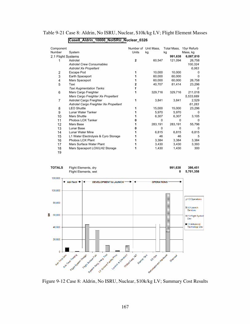
167
Table 9-21 Case 8: Aldrin, No ISRU, Nuclear, $10k/kg LV; Flight Element Masses
Case8_Aldrin_10000_NoISRU_Nuclear_0326
Component Number System
Number of Units
Unit Mass, kg
Total Mass, kg
15yr Refurb Mass, kg
2.1 Flight Systems 991,638 6,087,8101 Astrotel 2 60,547 121,094 26,758
Astrotel Crew Consumables 100,324Astrotel Xe Propellant 6,063
2 Escape Pod 1 10,000 10,000 03 Earth Spaceport 1 60,000 60,000 04 Mars Spaceport 1 60,000 60,000 26,7585 Taxi 2 40,707 81,414 23,296
Taxi Augmentation Tanks 1 06 Mars Cargo Freighter 1 329,716 329,716 211,018
Mars Cargo Freighter Xe Propellant 5,533,6897 Astrotel Cargo Freighter 1 3,841 3,841 2,529
Astrotel Cargo Freighter Xe Propellant 61,2838 LEO Shuttle 1 15,000 15,000 23,2969 Lunar Water Tanker 1 5,970 5,970 0
10 Mars Shuttle 1 6,307 6,307 3,10511 Phobos LOX Tanker 0 0 0 012 Mars Base 1 283,191 283,191 55,79613 Lunar Base 0 0 0 014 Lunar Water Mine 1 6,815 6,815 6,81515 L1 Water Electrolysis & Cyro Storage 1 46 46 516 Phobos LOX Plant 1 3,384 3,384 3,38417 Mars Surface Water Plant 1 3,430 3,430 3,39318 Mars Spaceport LOX/LH2 Storage 1 1,430 1,430 30019
TOTALS Flight Elements, dry 991,638 386,451Flight Elements, wet 0 5,701,358
Figure 9-12 Case 8: Aldrin, No ISRU, Nuclear, $10k/kg LV; Summary Cost Results

168
Table 9-22 Case 8: Aldrin, No ISRU, Nuclear, $10k/kg LV; Life Cycle Costs By WBS
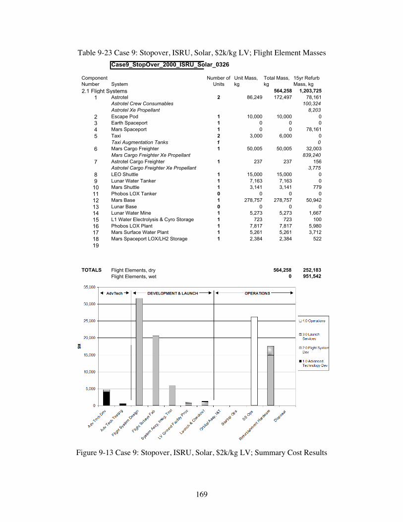
169
Table 9-23 Case 9: Stopover, ISRU, Solar, $2k/kg LV; Flight Element Masses
Case9_StopOver_2000_ISRU_Solar_0326
Component Number System
Number of Units
Unit Mass, kg
Total Mass, kg
15yr Refurb Mass, kg
2.1 Flight Systems 564,258 1,203,7251 Astrotel 2 86,249 172,497 78,161
Astrotel Crew Consumables 100,324Astrotel Xe Propellant 8,203
2 Escape Pod 1 10,000 10,000 03 Earth Spaceport 1 0 0 04 Mars Spaceport 1 0 0 78,1615 Taxi 2 3,000 6,000 0
Taxi Augmentation Tanks 1 06 Mars Cargo Freighter 1 50,005 50,005 32,003
Mars Cargo Freighter Xe Propellant 839,2407 Astrotel Cargo Freighter 1 237 237 156
Astrotel Cargo Freighter Xe Propellant 3,7758 LEO Shuttle 1 15,000 15,000 09 Lunar Water Tanker 1 7,163 7,163 0
10 Mars Shuttle 1 3,141 3,141 77911 Phobos LOX Tanker 0 0 0 012 Mars Base 1 278,757 278,757 50,94213 Lunar Base 0 0 0 014 Lunar Water Mine 1 5,273 5,273 1,66715 L1 Water Electrolysis & Cyro Storage 1 723 723 10016 Phobos LOX Plant 1 7,817 7,817 5,98017 Mars Surface Water Plant 1 5,261 5,261 3,71218 Mars Spaceport LOX/LH2 Storage 1 2,384 2,384 52219
TOTALS Flight Elements, dry 564,258 252,183Flight Elements, wet 0 951,542
Figure 9-13 Case 9: Stopover, ISRU, Solar, $2k/kg LV; Summary Cost Results

170
Table 9-24 Case 9: Stopover, ISRU, Solar, $2k/kg LV; Life Cycle Costs by WBS
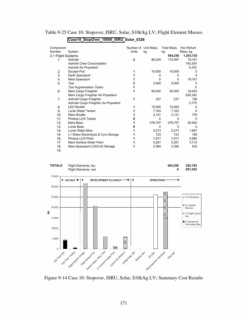
171
Table 9-25 Case 10: Stopover, ISRU, Solar, $10k/kg LV; Flight Element Masses
Case10_StopOver_10000_ISRU_Solar_0326
Component Number System
Number of Units
Unit Mass, kg
Total Mass, kg
15yr Refurb Mass, kg
2.1 Flight Systems 564,258 1,203,7251 Astrotel 2 86,249 172,497 78,161
Astrotel Crew Consumables 100,324Astrotel Xe Propellant 8,203
2 Escape Pod 1 10,000 10,000 03 Earth Spaceport 1 0 0 04 Mars Spaceport 1 0 0 78,1615 Taxi 2 3,000 6,000 0
Taxi Augmentation Tanks 1 06 Mars Cargo Freighter 1 50,005 50,005 32,003
Mars Cargo Freighter Xe Propellant 839,2407 Astrotel Cargo Freighter 1 237 237 156
Astrotel Cargo Freighter Xe Propellant 3,7758 LEO Shuttle 1 15,000 15,000 09 Lunar Water Tanker 1 7,163 7,163 0
10 Mars Shuttle 1 3,141 3,141 77911 Phobos LOX Tanker 0 0 0 012 Mars Base 1 278,757 278,757 50,94213 Lunar Base 0 0 0 014 Lunar Water Mine 1 5,273 5,273 1,66715 L1 Water Electrolysis & Cyro Storage 1 723 723 10016 Phobos LOX Plant 1 7,817 7,817 5,98017 Mars Surface Water Plant 1 5,261 5,261 3,71218 Mars Spaceport LOX/LH2 Storage 1 2,384 2,384 52219
TOTALS Flight Elements, dry 564,258 252,183Flight Elements, wet 0 951,542
Figure 9-14 Case 10: Stopover, ISRU, Solar, $10k/kg LV; Summary Cost Results

172
Table 9-26 Case 10: Stopover, ISRU, Solar, $10k/kg LV; Life Cycle Costs by WBS

173
Table 9-27 Case 11: Stopover, ISRU, Nuclear, $2k/kg LV; Flight Element Masses
Case11_StopOver_2000_ISRU_Nuclear_0326
Component Number System
Number of Units
Unit Mass, kg
Total Mass, kg
15yr Refurb Mass, kg
2.1 Flight Systems 927,781 6,474,9641 Astrotel 2 91,037 182,075 87,739
Astrotel Crew Consumables 100,324Astrotel Xe Propellant 8,601
2 Escape Pod 1 10,000 10,000 03 Earth Spaceport 1 0 0 04 Mars Spaceport 1 0 0 87,7395 Taxi 2 3,000 6,000 0
Taxi Augmentation Tanks 1 06 Mars Cargo Freighter 1 348,210 348,210 222,854
Mars Cargo Freighter Xe Propellant 5,844,0767 Astrotel Cargo Freighter 1 248 248 163
Astrotel Cargo Freighter Xe Propellant 3,9598 LEO Shuttle 1 15,000 15,000 09 Lunar Water Tanker 1 7,220 7,220 0
10 Mars Shuttle 1 3,141 3,141 77911 Phobos LOX Tanker 0 0 0 012 Mars Base 1 283,191 283,191 55,79613 Lunar Base 0 0 0 014 Lunar Water Mine 1 8,571 8,571 7,52415 L1 Water Electrolysis & Cyro Storage 1 756 756 10516 Phobos LOX Plant 1 47,216 47,216 42,52317 Mars Surface Water Plant 1 13,658 13,658 12,23618 Mars Spaceport LOX/LH2 Storage 1 2,496 2,496 54619
TOTALS Flight Elements, dry 927,781 518,004Flight Elements, wet 0 5,956,960
Figure 9-15 Case 11: Stopover, ISRU, Nuclear, $2k/kg LV; Summary Cost Results

174
Table 9-28 Case 11: Stopover, ISRU, Nuclear, $2k/kg LV; Life Cycle Costs by WBS

175
Table 9-29 Case 12: Stopover, ISRU, Nuclear, $10k/kg LV; Flight Element Masses
Case12_StopOver_10000_ISRU_Nuclear_0326
Component Number System
Number of Units
Unit Mass, kg
Total Mass, kg
15yr Refurb Mass, kg
2.1 Flight Systems 927,781 6,474,9641 Astrotel 2 91,037 182,075 87,739
Astrotel Crew Consumables 100,324Astrotel Xe Propellant 8,601
2 Escape Pod 1 10,000 10,000 03 Earth Spaceport 1 0 0 04 Mars Spaceport 1 0 0 87,7395 Taxi 2 3,000 6,000 0
Taxi Augmentation Tanks 1 06 Mars Cargo Freighter 1 348,210 348,210 222,854
Mars Cargo Freighter Xe Propellant 5,844,0767 Astrotel Cargo Freighter 1 248 248 163
Astrotel Cargo Freighter Xe Propellant 3,9598 LEO Shuttle 1 15,000 15,000 09 Lunar Water Tanker 1 7,220 7,220 010 Mars Shuttle 1 3,141 3,141 77911 Phobos LOX Tanker 0 0 0 012 Mars Base 1 283,191 283,191 55,79613 Lunar Base 0 0 0 014 Lunar Water Mine 1 8,571 8,571 7,52415 L1 Water Electrolysis & Cyro Storage 1 756 756 10516 Phobos LOX Plant 1 47,216 47,216 42,52317 Mars Surface Water Plant 1 13,658 13,658 12,23618 Mars Spaceport LOX/LH2 Storage 1 2,496 2,496 54619
TOTALS Flight Elements, dry 927,781 518,004Flight Elements, wet 0 5,956,960
Figure 9-16 Case 12: Stopover, ISRU, Nuclear, $10k/kg LV; Summary Cost Results

176
Table 9-30 Case 12: Stopover, ISRU, Nuclear, $10k/kg LV; Life Cycle Costs by WBS
9.3 Summary of MAMA Trade Study Results
This section summarizes the results of the various trade studies that were performed. Summaryresults are shown in Table 9-31 and Figure 9-17 and Figure 9-18. Note, the detail numbers inFigure 9-17 are different than in the “Life Cycle Costs by WBS” charts. In the WBS charts therefurbishment hardware in accounted for in Development costs and their launch costs are inLaunch costs. Because we want to correctly differentiate between non-recurring and sustaining,recurring costs we included the refurbishment hardware costs and their launch in Operationscosts. The launch costs in Figure 9-17 are only “Initial Launch” costs required to put the initialflight systems in space.

177
Table 9-31 MAMA Trade Studies and Summary Results
Several findings can be made from the trade study results:
1) Launch Costs are only a minor portion of the life-cycle costs (LCC) as long as costs are$2k/kg. The largest LCC element is Development followed by costs for 15 years ofOperations;
2) Operations costs range from $41.7-43.9B for Solar plus $2k/kg options and $45.5-53.7Bfor Solar and $10k/kg options. Operations costs for Nuclear options equal (at $2k/kg) orexceed (at $10k/kg) Development costs (however, nuclear systems were replaced at thesame rate as solar systems which may skew the nuclear recurring costs too high);
3) ISRU benefits are tightly tied to launch costs. Operations costs for the Aldrin cycleroption with ISRU about $2B less than the no ISRU option when launch costs are$2,000/kg, however this difference become $6B assuming $10,000/kg. The Aldrin cycleroption without ISRU but with Solar would need launch costs to be less than $865/kg tobe competitive with ISRU. This is a much lower launch cost than the $2,000/kg low-endof the range used for these trade studies. This launch cost analysis did not incorporatecost impacts for developing any new launch vehicles and treated launch costs as a serviceentirely captured by the $/kg value. Including these costs will increase $/kg values;
4) LCC for the Solar options is significantly lower than for the Nuclear options. Thisconclusion is strongly driven by the power levels used for a given architecture design;Since the Astrotels operated at only 160 kWe and most of the surface systems were on theorder of a MWe or less, the nuclear reactor design was penalized with a large minimummass; The power level at which the nuclear option would be less massive than the solaroption was not explored in this study;
5 ) The Stopover architecture LCC (Case 1) is $8B less than the Aldrin Low-thrustarchitecture LCC (Case 9), however the Operations costs are about $2B more. Whenlaunch costs are $10,000/kg, the Stopover Operations costs are about $12B moreexpensive than the Aldrin Low-thrust architecture.
6 ) Launch cost assumptions play a major role in determining which subsystem andarchitecture options are better.

178
Mars Astrotel Architecture Trade Study Cost Results
$0
$20,000
$40,000
$60,000
$80,000
$100,000
$120,000
$140,000
$160,000
$180,000
$200,000$M
Adv Tech $4,626 $4,626 $6,765 $6,765 $4,665 $4,665 $6,612 $6,612 $4,577 $4,577 $8,343 $8,343
Dev $69,208 $69,208 $97,746 $97,746 $68,907 $68,907 $92,337 $92,337 $59,491 $59,491 $103,491 $103,491
Initial Launch $1,892 $7,273 $2,790 $11,017 $1,920 $7,431 $2,739 $10,910 $1,625 $6,274 $2,678 $10,323
Ops $41,662 $45,541 $97,093 $143,790 $43,896 $51,362 $90,274 $140,438 $43,732 $53,651 $122,422 $175,775
Case 1 Case 2 Case 3 Case 4 Case 5 Case 6 Case 7 Case 8 Case 9 Case 10 Case 11 Case 12
Solar Nuclear Solar Nuclear Solar Nuclear
Aldrin w/ ISRU Aldrin w/o ISRU Stopover
Earth LV Cost Assumptions: - Odd numbered cases = $2K/kg - Even numbered cases = $10K/kg
Figure 9-17 Trade Study Cost Results
Mars Astrotel Trade Study Mass Results
0
1,000,000
2,000,000
3,000,000
4,000,000
5,000,000
6,000,000
7,000,000
kg
Initial Flight HW 653,037 653,037 998,339 998,339 668,800 668,800 991,638 991,638 564,258 564,258 927,781 927,781
Refurb HW 451,220 451,220 5,667,161 5,667,161 906,060 906,060 6,087,810 6,087,810 1,203,725 1,203,725 6,474,964 6,474,964
Case 1 Case 2 Case 3 Case 4 Case 5 Case 6 Case 7 Case 8 Case 9 Case 10 Case 11 Case 12
Solar Nuclear Solar Nuclear Solar Nuclear
Aldrin w/ ISRU Aldrin w/o ISRU Stopover
Earth LV Cost Assumptions: - Odd numbered cases = $2K/kg - Even numbered cases = $10K/kg
Figure 9-18 Trade Study Mass Results

179
9.4 Potential Applications/Extensions of the Modeling Concept
The MAMA modeling approach could be applied to support systems analyses of complexconcepts for a variety of different applications. The key benefits are improved understanding oflife cycle impacts from alternative system design approaches and different technologies.Sensitivity studies exploring benefits from technology improvements can be used to help directadvanced technology development efforts towards the highest leverage investments.

180
10 Astrotel Phase II Publications, Presentations, and PressReleases
10.1 Technical Papers or Articles� “Frequent, Fast Trips to and from Mars via Astrotels,” Paper and Presentation to the Space
Studies Institute/Princeton Conference on Space Manufacturing: The High FrontierConference XV, May 8, 2001
� CSM prepared and presented a paper titled "Conceptual Design of ISRU Propellant StorageDepots” at the 3rd Annual Space Resources Roundtable at CSM on October 25, 2001
� “Hyperbolic Rendezvous for Earth-Mars Cycler Missions,” Paper and Presentation atAAS/AIAA Space Flight Mechanics Meeting, San Antonio, Texas, 27-30 January 2002.
� “The Astrotel Scenario for Mars Exploration,” in Space Resources Roundtable Newsletter,Vol. 1, No. 1, April 6, 2002.
� “Earth-Mars Transportation Using Stop-over Cyclers,” paper and presentation to AIAAAstrodynamics Conference, Monterrey, CA, August 2002.
� “A Mars Cycler Architecture Utilizing Low-Thrust Propulsion,” paper and presentation toAIAA Astrodynamics Conference, Monterrey, CA, August 2002.
� “An Interplanetary Rapid Transit System Between Earth and Mars,” paper and presentationto the Space Technology & Applications International Forum, Albuquerque, NM, February2-5, 2003.
� “Interplanetary Rapid Transit to Mars,” paper and presentation to International Conferenceon Environmental Systems, Vancouver, Canada, July 7-10, 2003 (planned).
10.2 Media Interviews and Articles
� Space.com Interview, May 8, 2001 and Article in October 2001
� Interview for Swedish Educational TV, “University TV,” August 16, 2001� “Pendelsystem zwischen Erde und Mars,” in http://www.scienceticker.de/news
/EpkFlpZlAl.shtml.� “Main Belt transportation system?” in June 2002 Asteroid/Comet News in
http://www.hohmanntransfer.com/news/0206.htm.� “Earth-Mars Interplanetary Rapid Transit System,” in Cosmiverse, June 12, 2002 in
http://www3.cosmiverse.com/news/space/space06120205.html.� “2035-ben u ˝rhotel,u ˝rtaxi és u ˝rkiköto ˝a Marson,” in Tudomány, June 20, 2002, http://
www.origo.hu/tudomany/vilagur/200206202035ben.html.� “Astrotels might aid explorers’ Mars trips,” Floridatoday.com, July 2, 2002 in
http://www.floridatoday.com/news/space/stories/2002a/070202astrotels.htm.� “Cyclical visits to Mars via astronaut hotels,” in Scientecmatrix.com, http://www.
scientecmatrix.com/seghers/tecma/scientecmatrix.nsf/_/E70654D46DCC705DC1256BD500372664.

181
10.3 Briefings and Presentations
� Briefing to the NASA Institute for Advanced Concepts (NIAC) 3rd Annual Meeting: Visionsof the Future in Aeronautics and Space, June 5, 2001
� Astrotel Team Meeting and Presentations at the Colorado School of Mines, July 13, 2001� Presentation prepared for the NASA Associate Administrator for Human Exploration and the
Development of Space, September 11, 2001 (Meeting Cancelled)
� Briefing to the Exploration Office NASA Johnson Space Center, November 27, 2001
� Briefing to the NASA Institute for Advanced Concepts (NIAC) 4th Annual Meeting,Houston, TX, June 12, 2002
� Briefing to the Exploration Office NASA Johnson Space Center, June 10, 2002
� “Cyclic Visits To Mars Via Astronaut Hotels or The Interplanetary Rapid Transit (IRT)System,” presentation to Transformational Space Concepts and Technologies (TSCT) forSpace Missions Human Exploration and Development of Space Enterprise (HEDS)Technology Interchange Meeting, Pasadena, CA, January 14-16, 2003.

182
11 Summary
This report describes the work accomplished and results obtained during the Phase II of thedevelopment of an innovative and new concept for a Cyclical Visits to Mars via AstronautHotels in support of the NASA Institute for Advanced Concepts. During the Phase II, we havemade significant progress as evidenced by the following summary of key accomplishments:
� Written and presented 8 technical papers at a variety of conferences,
� interviewed for Swedish TV and Space.com plus several media contacts resulting in webor print media coverage,
� selected a lunar orbit radius (LOR) location for the Earth Spaceport,
� completed a comprehensive analysis, modeling, and design of ISRU systems,
� developed concepts for providing reasonable launch periods for Taxi vehicles undergoinghyperbolic rendezvous with Astrotels,
� developed, analyzed and optimized the Mars Shuttle entry and ascent trajectories,
� completed detailed design studies of Mars Shuttle vehicle,
� completed detailed design studies of three-stage Taxi vehicle,
� briefed the NASA JSC Exploration Office on the concept and the progress of the study,
� developed several architecture and subsystem options and compared their masses andcosts with MAMA,
� completed this Final Report.
During Phase II, we estimate that we have met nearly 100% of our objectives though there is stillmuch to be done.

183
Appendix: 33rd International Conference on EnvironmentalSystems Paper

Paper Number: 03 ICES-295
Interplanetary Rapid Transit to Mars
Kerry Nock, Angus McRonald, Paul Penzo, and Chris WyszkowskiGlobal Aerospace Corporation
Michael Duke, Robert King, Lee JohnsonColorado School of Mines
Mark Jacobs, Jerry RauwolfScience Applications International Corporation
Copyright © 2003 SAE International
ABSTRACT
A revolutionary interplanetary rapid transit concept fortransporting scientists and explorers between Earth andMars is presented by Global Aerospace Corporationunder funding from the NASA Institute for AdvancedConcepts (NIAC) with support from the Colorado Schoolof Mines, and Science Applications InternationalCorporation. We describe an architecture that useshighly autonomous spaceships, dubbed Astrotels; smallTaxis for trips between Astrotels and planetarySpaceports; Shuttles that transport crews to and fromorbital space stations and planetary surfaces; and low-thrust cargo freighters. In addition we discuss theproduction of rocket fuels using extraterrestrial materials;aerocapture to slow Taxis at the planets; and finallydescribe a number of trade studies and their life-cyclecost results.
INTRODUCTION
Someday scientists and explorers will regularly travel toMars for research and exploration as they now travel toAntarctica. Knowing this eventuality enables us to planfor the future. As with the South Pole Base at Antarctica,an efficient transportation system will be needed torotate crews back and forth between Earth and Mars andto resupply equipment and fuels.
Global Aerospace Corporation and its partners havedeveloped an innovative architecture that uses highlyautonomous, solar-powered, xenon ion-propelledspaceships, dubbed Astrotels; small Taxis spaceshipsfor trips between Astrotels and planetary Spaceports;Shuttles that transport crews to and from orbital spacestations and planetary surfaces; and low-thrust cargofreighters that deliver hardware, fuels and consumablesto Astrotels and Spaceports.
Astrotels can orbit the Sun in cyclic orbits between Earthand Mars and Taxis fly hyperbolic planetary trajectoriesbetween Astrotel and Spaceport rendezvous. Togetherthese vehicles transport replacement crews of 10 peopleon frequent, short trips between Earth and Mars. Twocrews work on Mars with alternating periods of duty,each spending about 4 years there with crew transfersoccurring about every two years. The production ofrocket fuels has been studied using materials minedfrom the surfaces of the Moon, Mars and the Martiansatellites. The use of the atmospheres of the planetsthemselves to slow Taxis, called aerocapture, has beendeveloped and analyzed. A tool has been constructedthat can estimate the life-cycle cost of a transportationarchitecture and its various options.
This concept provides a framework and context forfuture technology advance and robotic missionexploration. The human exploration program couldbenefit from a focus on permanent Mars habitation,instead of brief and expensive expeditions; lunar andPhobos exploration as steps to Mars; and evolutionaryvehicle and system development toward a Marstransportation infrastructure. The inevitability of humanMars exploration will be much closer once we begintaking these steps.
MARS BASE TRANSIT STOP
The level of capability envisioned at the Mars Basesupports significant surface activities in the areas ofscience exploration, resource surveys, life-cyclemaintenance, propellant production, and materialsprocessing and fabrication. These activities will takeplace at one or two fixed-site facilities on Mars and ondistant traverses from the base. Such operations willrequire a high degree of mobility, appropriate levels ofautomation with efficient man-machine interfaces, andthey require crews that combine the need for individual
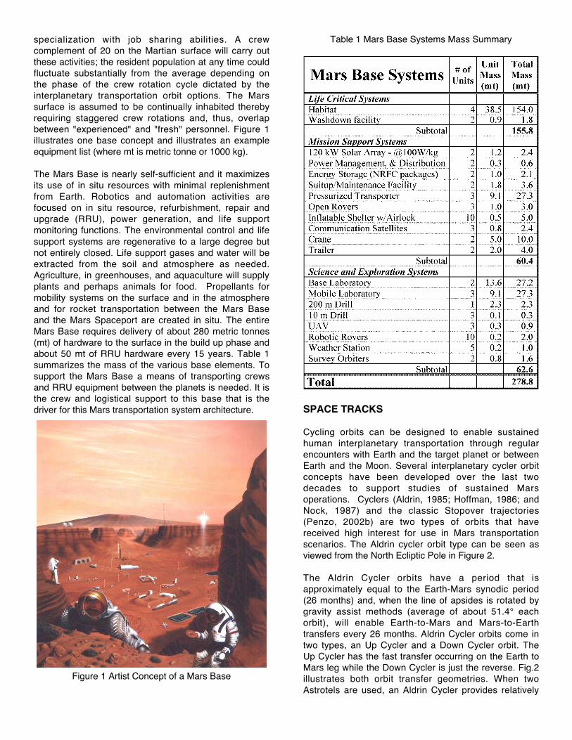
specialization with job sharing abilities. A crewcomplement of 20 on the Martian surface will carry outthese activities; the resident population at any time couldfluctuate substantially from the average depending onthe phase of the crew rotation cycle dictated by theinterplanetary transportation orbit options. The Marssurface is assumed to be continually inhabited therebyrequiring staggered crew rotations and, thus, overlapbetween "experienced" and "fresh" personnel. Figure 1illustrates one base concept and illustrates an exampleequipment list (where mt is metric tonne or 1000 kg).
The Mars Base is nearly self-sufficient and it maximizesits use of in situ resources with minimal replenishmentfrom Earth. Robotics and automation activities arefocused on in situ resource, refurbishment, repair andupgrade (RRU), power generation, and life supportmonitoring functions. The environmental control and lifesupport systems are regenerative to a large degree butnot entirely closed. Life support gases and water will beextracted from the soil and atmosphere as needed.Agriculture, in greenhouses, and aquaculture will supplyplants and perhaps animals for food. Propellants formobility systems on the surface and in the atmosphereand for rocket transportation between the Mars Baseand the Mars Spaceport are created in situ. The entireMars Base requires delivery of about 280 metric tonnes(mt) of hardware to the surface in the build up phase andabout 50 mt of RRU hardware every 15 years. Table 1summarizes the mass of the various base elements. Tosupport the Mars Base a means of transporting crewsand RRU equipment between the planets is needed. It isthe crew and logistical support to this base that is thedriver for this Mars transportation system architecture.
Figure 1 Artist Concept of a Mars Base
Table 1 Mars Base Systems Mass Summary
SPACE TRACKS
Cycling orbits can be designed to enable sustainedhuman interplanetary transportation through regularencounters with Earth and the target planet or betweenEarth and the Moon. Several interplanetary cycler orbitconcepts have been developed over the last twodecades to support studies of sustained Marsoperations. Cyclers (Aldrin, 1985; Hoffman, 1986; andNock, 1987) and the classic Stopover trajectories(Penzo, 2002b) are two types of orbits that havereceived high interest for use in Mars transportationscenarios. The Aldrin cycler orbit type can be seen asviewed from the North Ecliptic Pole in Figure 2.
The Aldrin Cycler orbits have a period that isapproximately equal to the Earth-Mars synodic period(26 months) and, when the line of apsides is rotated bygravity assist methods (average of about 51.4° eachorbit), will enable Earth-to-Mars and Mars-to-Earthtransfers every 26 months. Aldrin Cycler orbits come intwo types, an Up Cycler and a Down Cycler orbit. TheUp Cycler has the fast transfer occurring on the Earth toMars leg while the Down Cycler is just the reverse. Fig.2illustrates both orbit transfer geometries. When twoAstrotels are used, an Aldrin Cycler provides relatively

short transit times (~5 months) and regular transitopportunities. However, the planetary encounters occurat high relative velocities and typically, impose harsherrequirements on the Taxi craft than other cyclers. Also,the Aldrin Cycler requires a modest mid-coursecorrection on 3 out of 7 orbits to maintain the proper orbitorientation. These delta-Vs will be carried out using low-thrust, solar powered ion propulsion systems (IPS).
Figure 2 Aldrin Cycler Orbits
Stopover Cyclers are direct transfers from Earth to Marswith high-thrust propulsive maneuvers at both ends ofthe trajectory and a stop at each planet. StopoverCyclers require two Astrotels operating. Flight timevaries between 4-7 months depending on opportunityand propellant loading. Stay time at Mars is identical tothe Semi-cyclers or about 1.5 years. Advantages ofStopover Cyclers are low departure and arrival velocitiesfor a given flight time, flexible launch and arrival dates,elimination of the hyperbolic rendezvous, close vicinity ofthe station to the planet for replenishment andrefurbishment, and alternate mission uses for thestations while in orbit about each planet, waiting for thenext opportunity to return.
At this time, the Aldrin Cycler orbits have been selectedas the reference because of several key advantages.One advantage is that Astrotels do not require high-thrust chemical propulsion systems, whereas, in theStopover Cycler concept, high-thrust propulsion must beused to keep the flight time short. Another importantadvantage of Aldrin Cyclers is that the Astrotels neverstop. The implication of this advantage, combined withthe use of low-thrust systems, is that one canincrementally increase the Astrotel capability over timewith very little propulsion cost. Example increasedcapabilities include more radiation shielding,incorporation of artificial gravity if desired, redundancy inthe form of additional Taxi and/or escape vehicles, and a
growing cache of repair hardware, propellants andconsumables at the Astrotel. Finally, by using the low-thrust Aldrin Cyclers, only two Astrotel vehicles need tobe constructed and maintained.
GETTING ON AND OFF THE TRAIN
Cycler orbits with Earth and Mars hyperbolic flybysnecessitate transfers between a planetary Spaceportand an Astrotel via a Taxi vehicle. The Astrotel flyby iscompletely constrained in periapsis date, distance, andinclination, since it must continue to travel on its desiredcycler path between the planets. One of the majorconcerns in the use of cyclers for human transportationhas been the hyperbolic rendezvous where the Taxideparts the Earth with a near instantaneous launchperiod without any margin for error or hardware delay.The primary restriction here is that the rendezvous musttake place within about 7 days from the time of departurefrom the Spaceport because Taxi vehicles have limitedconsumables and life support and are lightly shieldedagainst radiation. Figure 3 (adapted from Penzo andNock 2002a) shows the Spaceport orbit, the Astrotelflyby and three Taxi hyperbolic rendezvous options. Wehave selected the 3-burn option for the referencebecause it requires a low total delta-V and a short flighttime. The 4-burn option has a lower delta-V however aprohibitively long transit time for a Taxi. The 3-burnoption consists of a Taxi departure maneuver, ∆V1, tolower periapsis altitude for the injection delta-V, ∆V2,followed several days later by the rendezvousmaneuver, ∆V3.
Figure 3 Hyperbolic Rendezvous Options
Having to solve the hyperbolic rendezvous problemprovides insight into the desired location of the EarthSpaceport. Plane changes are best made far from theplanet where the orbital velocities are low. Velocitychanges are best made close to the planet, i.e. withinthe gravity well. In LEO, the orbital velocity is almost 8km/s, whereas at lunar distance, the velocity is about 1km/s, which is a better place to make a required planechange.
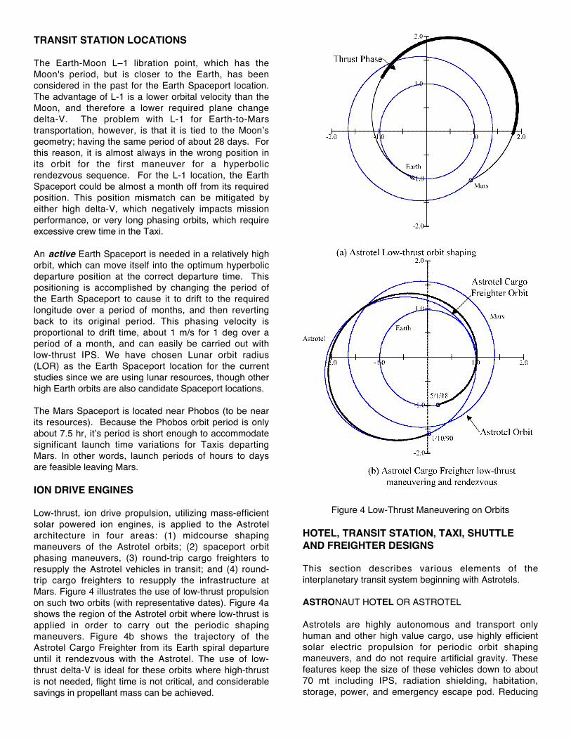
TRANSIT STATION LOCATIONS
The Earth-Moon L–1 libration point, which has theMoon's period, but is closer to the Earth, has beenconsidered in the past for the Earth Spaceport location.The advantage of L-1 is a lower orbital velocity than theMoon, and therefore a lower required plane changedelta-V. The problem with L-1 for Earth-to-Marstransportation, however, is that it is tied to the Moon’sgeometry; having the same period of about 28 days. Forthis reason, it is almost always in the wrong position inits orbit for the first maneuver for a hyperbolicrendezvous sequence. For the L-1 location, the EarthSpaceport could be almost a month off from its requiredposition. This position mismatch can be mitigated byeither high delta-V, which negatively impacts missionperformance, or very long phasing orbits, which requireexcessive crew time in the Taxi.
An active Earth Spaceport is needed in a relatively highorbit, which can move itself into the optimum hyperbolicdeparture position at the correct departure time. Thispositioning is accomplished by changing the period ofthe Earth Spaceport to cause it to drift to the requiredlongitude over a period of months, and then revertingback to its original period. This phasing velocity isproportional to drift time, about 1 m/s for 1 deg over aperiod of a month, and can easily be carried out withlow-thrust IPS. We have chosen Lunar orbit radius(LOR) as the Earth Spaceport location for the currentstudies since we are using lunar resources, though otherhigh Earth orbits are also candidate Spaceport locations.
The Mars Spaceport is located near Phobos (to be nearits resources). Because the Phobos orbit period is onlyabout 7.5 hr, it’s period is short enough to accommodatesignificant launch time variations for Taxis departingMars. In other words, launch periods of hours to daysare feasible leaving Mars.
ION DRIVE ENGINES
Low-thrust, ion drive propulsion, utilizing mass-efficientsolar powered ion engines, is applied to the Astrotelarchitecture in four areas: (1) midcourse shapingmaneuvers of the Astrotel orbits; (2) spaceport orbitphasing maneuvers, (3) round-trip cargo freighters toresupply the Astrotel vehicles in transit; and (4) round-trip cargo freighters to resupply the infrastructure atMars. Figure 4 illustrates the use of low-thrust propulsionon such two orbits (with representative dates). Figure 4ashows the region of the Astrotel orbit where low-thrust isapplied in order to carry out the periodic shapingmaneuvers. Figure 4b shows the trajectory of theAstrotel Cargo Freighter from its Earth spiral departureuntil it rendezvous with the Astrotel. The use of low-thrust delta-V is ideal for these orbits where high-thrustis not needed, flight time is not critical, and considerablesavings in propellant mass can be achieved.
Figure 4 Low-Thrust Maneuvering on Orbits
HOTEL, TRANSIT STATION, TAXI, SHUTTLEAND FREIGHTER DESIGNS
This section describes various elements of theinterplanetary transit system beginning with Astrotels.
ASTRONAUT HOTEL OR ASTROTEL
Astrotels are highly autonomous and transport onlyhuman and other high value cargo, use highly efficientsolar electric propulsion for periodic orbit shapingmaneuvers, and do not require artificial gravity. Thesefeatures keep the size of these vehicles down to about70 mt including IPS, radiation shielding, habitation,storage, power, and emergency escape pod. Reducing

its mass significantly reduces the total propulsive energybudget required for course corrections to the 2767-kgpropellant required for all major corrections over 15years. The 70-mt mass includes a habitability module fora crew of ten. The size and volume of this system wouldprovide a crew volume of about 6-times that available totoday’s Space Shuttle crew. Figure 5 is a schematic ofone concept for an Astrotel that is approaching Mars.The two smaller modules between the TransHab and thesolar array are cargo bays. The Astrotel Cargo Freighterautonomously delivers all cargo to the Astrotel containedwithin a standard cargo bay. These are pressurizedmodules to facilitate crew unloading of consumables andRRU hardware. Once emptied the cargo bay could bediscarded or used to provide added crew volume. Table3 summarizes the Astrotel components and theirmasses.
Figure 5 Astrotel Concept
TRANSIT STATIONS
Spaceports are collection points for the arrival anddistribution of humans, cargo and propellants destinedfor transport to planet or natural satellite surfaces or tocycling Astrotels. In past architectures such Spaceportswere large, rotating, permanently crewed platforms. Inthis new concept, a Spaceport is based on the Astroteldesign philosophy. Crew stay times are limited in orderto minimize effects of zero-g. Crew maintenance isminimized by maximum application of autonomy in orderto shorten stay times. Station-keeping, orbit corrections,orbit-phasing delta-Vs could easily be performed by thesame or even smaller IPS system envisioned for theAstrotels.
Table 2 Astrotel Equipment Mass Summary
TAXIS AND USING THE ATMOSPHERE TO PUT THEBRAKES ON
Taxis provide transportation between Spaceports andAstrotels. In order to minimize propulsive energy use,Taxis use advanced aeroassist technologies forplanetary orbit capture. Aerocapture takes maximumadvantage of planetary atmospheric drag to slow thevehicle on its approach from planetary space. The keysizing assumptions are: a.) Minimal radiation protectionfor the crew is provided since transfer times to/from theAstrotels is less than 7 days, b.) No cargo is transportedto the Astrotel by the Taxi, c.) 15% of the entry mass isaeroshell, d.) LOX/LH propulsion system at Isp of 460 sand thrust of 60,000 lbs./engine, e.) Fuel cell energystorage, no solar array power source, and f.) Propellanttank augmentation (expendable drop tanks and in somecases additional engines) is required at Mars. Taxisescape planets and are placed onto hyperbolicrendezvous trajectories with Astrotels. Rendezvous timeto Astrotels is measured in days in order to reduce theduration of crew time in the expected cramped quarters,since crew volume is comparable to Apollo. Figure 6illustrates the Taxi departing Earth. Figure 7 illustratesthe common crew module.
Table 3 summarizes the system mass of the commoncrew module. This crew module is used in both the Taxiand the Mars Shuttle, to be discussed later. Table 4summarizes the overall mass breakdown of the Taxisystem.
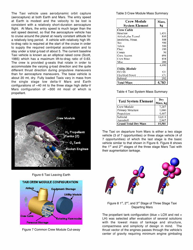
The Taxi vehicle uses aerodynamic orbit capture(aerocapture) at both Earth and Mars. The entry speedat Earth is modest and the velocity to be lost isconsistent with a relatively short-duration aerocaptureflight. At Mars, the entry speed is much larger than theexit speed desired, so that the aerocapture vehicle hasto cruise around the planet at nearly constant altitude fora relatively long period. A vehicle with relatively high lift-to-drag ratio is required at the start of the cruise in orderto supply the required centripetal acceleration and tostay under a total g-load of about 5. The current baselineTaxi vehicle is known as an elliptical raked cone (Scott,1985) which has a maximum lift-to-drag ratio of 0.63.The crew is provided g-seats that rotate in order toaccommodate the varying g-load direction and the quitedifferent thrust direction during propulsive maneuversthan for aerocapture maneuvers. The base vehicle isabout 20 mt, dry. Fully loaded Taxis vary in mass fromthe single stage low delta-V Mars and Earthconfigurations of ~40 mt to the three stage high delta-VMars configuration of ~300 mt most of which ispropellant.
Figure 6 Taxi Leaving Earth
Figure 7 Common Crew Module Cut-away
Table 3 Crew Module Mass Summary
Table 4 Taxi System Mass Summary
The Taxi on departure from Mars is either a two stagevehicle (3 of 7 opportunities) or three stage vehicle (4 of7 opportunities) of which the last stage is the basicvehicle similar to that shown in Figure 6. Figure 8 showsthe 1st and 2nd stages of the three stage Mars Taxi withtheir augmentation tankage.
Figure 8 1st, 2nd, and 3rd Stage of Three Stage TaxiDeparting Mars
The propellant tank configuration (blue = LOX and red =LH) was selected after evaluation of several solutionswith the lowest mass of tankage and structure,compactness and simplicity of design in mind. Thethrust vector of the engines passes through the vehicle’scenter of gravity requiring minimum engine gimbaling

(within ±5 deg) during operation of all three stages,including 3rd stage with empty tanks. All propellant tanksexcept the 2nd stage LOX tank are spherical. The 2nd
stage LOX tank is cylindrical with hemispherical headsand performs dual functions: besides storing LOX it isused as the main structural element supporting all 1st
stage tanks and 2nd stage LH tanks and transferringresulting forces to the 3rd stage. Aluminum tank jacketsincludes multi-layer insulation (MLI). The 3rd stage tanks(two LOX and two LH tanks) are supported by Aeroshellstructure (reinforcing ribs). The shells are reinforced toproperly distribute dynamic pressure and concentratedsupport loads. The 2nd stage LOX tank is connected totwo central Aeroshell reinforcing ribs similar to a boatkeel. The attachments, besides small bending moment,are loaded with dynamic force resulting from theacceleration of the 1st and 2n d stages, transferredthrough 2nd stage LOX tank shell and reinforcing rings.Four 2nd stage LH tanks are attached to front reinforcingring of the 2nd stage LOX tank by tension members andsupported on its rear reinforcing ring. Tension membersare tangential to the respective tank shells. The 1st
stage LH tanks are similarly attached to the 1st stageLOX tank and supported on the 2nd stage LOX tank frontreinforcing ring. The 1st stage LOX tank, by far theheaviest component of the system, is supported from the2nd stage LOX tank front reinforcing ring. All the tanksare internally and/or externally reinforced so theconcentrated as well as dynamic pressure loads areproperly distributed to the shell.
The Taxi is propelled with three Pratt & Whitney RL 60engines, rated at 60,000 lbs. each. The engines may begimbaled ±5°, both vertically and horizontally. All threeengines are shown installed in a common frame but inthe future individual gimbals and actuators for eachengine will be designed (an earlier two engine version ofthe Taxi is shown in Figure 6).
MARS SHUTTLE
The Mars Shuttle transports a crew of 10 to and from theMars Base and the Mars Spaceport near Phobos. TheMars Shuttle supports crew needs during the very shorttransit (<1 days) between the Mars Base and the MarsSpaceport. In addition, the Mars Shuttle carries outdelta-V maneuvers, performs aero-entry and landingmaneuvers within the Martian atmosphere, navigatesautonomously during all maneuvers, provides electricalpower to its subsystems and carries RRU cargo from theMars Spaceport to the Mars Base. The Mars Shuttle isdesigned to travel only between the Mars surface andthe Mars Spaceport at Phobos. The basic vehicle is alow lift/drag ratio design with a deployable 20-mdiameter aerobrake used during entry and landing. Attake-off, the aerobrake is stowed to reduce atmosphericcross-section and minimize drag. The low lift/drag ratiodesign offers reduced mass, ease of fabrication, reducedcost and growth accommodation over higher lift/drag
designs. The Mars Shuttle mass is 67 mt fully loaded, 42mt at entry, 32 mt landed and 22 mt dry. Figure 9illustrates computer-generated designs of the MarsShuttle in its entry and launch configurations.
Figure 9 Mars Shuttle Configuration
TURNING PLANET DIRT INTO ROCKET FUEL
The use of planetary resources significantly reduces thematerial that needs to be brought up through the gravitywell of the Earth and delivered to a planetarytransportation node. The energy required fortransportation of propellant is proportional to the squareof the velocity change that it must undergo. For example,the energy required conveying propellant from the Moonto L-1 is approximately 1/30th of that required from theEarth’s surface to L-1 and requires a much simplerspacecraft. The transportation architecture includes theuse of in situ resources at the Moon (lunar polar waterice), at Phobos (O2 production from carbon reduction ofthe regolith), and on the surface of Mars (heat extractionof water from regolith, electrolysis, O2/H2 liquefaction andstorage). In addition, there are off-world processing andstorage facilities including a water electrolysis, O2/H2
liquefaction and storage at the Earth Spaceport andO2/H2 storage at the Mars Spaceport. The baselinearchitecture requires resource production rates of 15.4kg/hr of Phobos LOX, 6.6 kg/hr of Martian water, 10.2kg/hr of lunar water, and 1.6 kg/hr of LOX/LH from lunarwater at the Earth Spaceport. Production rates accountfor the lower duty cycle of planetary solar power(Phobos, Moon, and Mars).
Excavation
It is a challenge to design excavation and extractionsystems for Phobos, Mars and the Moon since they lacksignificant, or any, atmospheres, gravity is low toextremely low, and temperature variations are extremelyhigh. In addition to operating under these extremeenvironments, a Phobos excavation system requiresobstacle avoidance, rock sorting, continuous excavationduty cycle, excavator flexibility, and a low mass. Abucket-wheel excavator system (BWE) specificallydesigned for extraterrestrial environments, as shown inthe left of Figure 10, was found to meet all theserequirements (Johnson, 2002). The BWE excavatescontinuously and simultaneously transports the materialsto storage. Excavation forces are primarily horizontal

and provided by the mass of the entire excavator insteadof only the bucket mass allowing the BWE to work inextremely low gravity without exterior anchoring,provided its mass provides ample traction for excavationand forward movement.
Extractors and Reactors
On the Moon and Mars relatively low temperatures(100°C to 500°C) are required to boil off the water fromthe soil (assumed in a 1% abundance by weight) afterwhich is collected, liquefied and stored in preparationeither for transport to the Earth Spaceport or for furtherprocessing into rocket fuel at Mars. At Phobos the soil isplaced in a Carbothermal reactor where combined withhigh temperatures (1700 °C) and hydrogen and carbon,oxygen is produced. After producing the oxygen it isliquefied for eventual transport to the Mars Spaceport forlong-term storage.
Processing
Except for rocket fuels needed to launch from thesurface of the Moon, producing LOX/LH from lunar wateris done at the Earth Spaceport (by means of electrolysisand liquefaction) where an abundant supply of solarenergy is available. Processing of Martian water occursnear the Mars Base after which LOX/LH are stored foruse by the Mars Shuttle.
Figure 10 Bucket Wheel Excavator and Transporter
WHAT’S THE BEST TRANSIT SYSTEM ANDHOW MUCH WILL IT COST TO OPERATE?
A computerized model has been developed thatdescribes the baseline architecture and a number ofoptions and generates life-cycle cost (LCC) estimates.These life-cycle estimates are best used to comparecompeting options rather than establishing credibleestimates of the real total cost of such an architecture.The model is highly integrated and interrelated includingtransportation vehicles; ground systems; subsystemtechnology assumptions; in situ resource assumptions
and systems; and celestial mechanics analysis. Themodel was developed to facilitate integration of varioussystem elements, to facilitate overall architecture tradestudies and to support life cycle cost analysis. Thisapproach allowed independent development of individualelements and supporting analyses by focusing on therelationships among the system elements andestablishing element-to-element links for selectedinputs/outputs. A detailed work breakdown structure wasdeveloped including Advanced TechnologyDevelopment, Flight System Development, Launch andOperations. Costs were tracked at one and two levelsbelow the main categories. Cost references were a mixof actual data from past missions and component-levelperformance parametrics developed by technologyspecialists in NASA, industry and academia. The 15-year operations costs for the transportation architectureoptions are displayed. This model can perform tradestudies so one can vary system capabilities orarchitecture assumptions and hence compare cargomass and in situ resource requirements and eventuallylife-cycle costs. In the current version of the model, thereare over 100 individual sub elements
This model is best at comparing life-cycle costs ofdifferent architecture options. Several cost estimateswere generated varying a number of assumptionsincluding (a) basic trajectory type (Aldrin Low-thrustCycler vs. Stopover Cycler), (b) launch costs ($2k or$10k), (c) with and without ISRU, and (d) use of solar ornuclear for surface and space power sources. Thesecost estimates are compared in Figure 11 below. It isinteresting to note that the LCC for the solar option aresubstantially lower than for the nuclear option. Thereasons for this are that the solar array powerrequirements, masses and costs are low and the nuclearsystems are very expensive to develop even if small. Ifthe power requirements had been substantially higherthe nuclear option would look better. Another interestingthing to note is that for launch costs of $2k/kg there isnot a significant benefit of ISRU in lowering LCC (onestill needs to look at the operations costs to see ifsustained operations costs would be significantly lower).However, when launch costs are $10k/kg theredifference is much greater between the ISRU and non-ISRU cases. Figure 12 compares cost elementsbetween the Aldrin and Stopover architectures. Ofinterest is the fact that the development costs are about$10 B less for the Stopover architecture, however theoperations costs are higher.
The baseline Mars Astrotel scenario (Aldrin, $2k, solar,plus ISRU) life-cycle cost of $117 B is split between $5 Bfor advanced technical development, $69 B for flightsystem development, $1 B for launch services and$42 B for operations over 15 years. The total sustainedoperations costs are estimated at $2.8 B per year, orabout 20% of the current NASA budget.

Figure 11 Life-Cycle Cost Comparison with Architecture Options
Figure 12 Comparison of Cost Elements between theAldrin and Stopover Architectures
SUMMARY
There are a number of choices in future Mars explorationplanning. One can follow the Apollo expeditionapproach, characterized as "flags and footprints", thathas resulted in an absence of human exploration of theMoon for over a quarter century. Or one can develop anevolutionary approach to Mars exploration by
establishing and using elements of the infrastructureneeded to eventually maintain a human presence onMars. The first choice will get humans to Mars but in theprocess we may damage political and public support tothe extent that, like Apollo, Mars exploration is eventuallyabandoned. The latter choice lays the foundation for lowlife-cycle cost transportation that has a much higherprobability of sustained political and public support.
If we know what systems and vehicles will be required inthe future to support a Mars transportation architecture,the steps to the development of this infrastructure can beconstructed including the long-range planning andcosting, advanced technology development, advancedsystem development and flight-testing. Intermediatevehicle or surface systems can begin to be used,perhaps for lunar or Phobos exploration, as they aredeveloped with the knowledge that their efficiency isdriven not necessarily by their immediate use but bytheir eventual application in the overall infrastructure.
A key example of providing a context for futuretechnology development is the assessment of the needfor and development cost of nuclear power generationsystems in a future architecture. If such systems are notabsolutely required, or result in higher life-cycle coststhan solar systems, as discussed above, then we cansave considerable time and precious resources by notpursing the nuclear option.

A key question is the need for ISRU systems andwhether they are cost effective. The answer to thequestion will require a better understanding of the futureof launch costs. If launch costs can really be reduced tothe order of $2k/kg the argument for ISRU may be lessstrong than if these costs are really $10k/kg. In addition,how ISRU fits into future near-Earth operations needs tobe evaluated in order to determine if the development,and a portion of the operations costs, can be amortizedbeyond the Earth to Mars transportation needs.
The concepts envisioned by this systems architecturehave a potential role to play in the expedition phase ofMars exploration. The application of these orbit andsystems concepts in the expedition phase of Marsexploration may serve to reduce overall missiondevelopment costs and improve overall mission reliabilityand safety. Once launched into cycling orbits, Astrotelscan orbit indefinitely as long as they are periodicallymaintained, improved and supplied with orbit correctionpropellants. In addition, the result of embracing such amission concept early in an expedition phase means thata permanent inhabitation phase of Mars is closer. Animplication of pursuing this path toward a Marstransportation architecture is near-term development ofintermediate systems of immediate benefit to humanspace exploration, which have a role to play in theexpedition phase of human Mars exploration.
By establishing the goal of developing a Marstransportation architecture, planning and mission contextis provided for robotic and human space exploration.Without this framework, we may expend valuableresources on extraneous technologies and dead-endsystem developments.
ACKNOWLEDGMENTS
We would like to acknowledge the support of the NASAInstitute for Advanced Concepts through theirUniversities Space Research Association Contracts Nos.07600-49 and 07600-59. In addition, we acknowledgethe efforts of those who participated in this workincluding Dr. Kim M. Aaron, Dale R. Burger, and BrendaWistor-Linfield of Global Aerospace Corporation; Alan L.Friedlander of Science Applications InternationalCorporation; and Professors Robert Knecht, DaveMunoz, Ron Miller, and Colin Wolden along with many oftheir students at the Colorado School of Mines.
REFERENCES
Aldrin, E. E., "Cyclic trajectory concepts. SAICpresentation to the Interplanetary Rapid Transit StudyMeeting," Jet Propulsion Laboratory October 28, 1985.
Hoffman, S. Friedlander, A. and Nock, K.,"Transportation Performance Comparison for aSustained Manned Mars Base," AIAA Paper No. 86-
2016-CP, AIAA/AAS Astrodynamics Conference,Williamsburg, Va (1986).
Johnson, L., King, R. H., and Duke, M., "ExtraterrestrialIn Situ Resource Systems Concepts Development,"Final Report submitted to Global AerospaceCorporation by the Center for Commercial Applicationsof Combustion in Space, Colorado School of Mines,February 25, 2002.
Nock, K. T. and Friedlander, A., "Elements of a MarsTransportation System," Acta Astronautica, 15, No.6/7, 505-522 (1987).
Nock, K., Frequent, "Fast Trips To and From Mars ViaAstrotels," paper at Space Studies Institute/PrincetonConference on Space Manufacturing: High FrontierConference, Princeton University, May 2001.
Penzo, P. A. and Nock, K. T., "Hyperbolic Rendezvousfor Earth-Mars Cycler Missions," paper AAS-02-162,AAS/AIAA Space Flight Mechanics Meeting, SanAntonio, TX, January 2002a.
Penzo, P. A., "Earth-Mars Transportation Using Stop-Over Cyclers," AIAA Astrodynamics Conferencepaper, Monterey, CA, August 2002b.
Scott, C. D., et al., "Design Study of an IntegratedAerobraking Orbital Transfer Vehicle," NASA TM58264, March 1985.