cylindrical concentrators as a limit case of toroidal concentrators
TRANSCRIPT

Cylindrical concentrators as a limit case of toroidalconcentrators
Juan C. Minano
Cylindrical concentrators are viewed as a limit case of toroidal concentrators with the purpose of applyingto them some results obtained for axisymmetrical optical systems. This enables us to obtain easily the di-
rectional intercept factor of a cylindrical nonimaging concentrator called the Ideal Tubular Concentrator.A useful tool for designing new cylindrical concentrators is also derived.
1. Introduction
A cylindrical (or linear) concentrator can be viewedas a toroidal concentrator which occupies a region of thespace infinitely far from its axis of symmetry. Since atoroidal structure is axisymmetrical, this allows us toapply to the cylindrical optical system (COS) some re-sults obtained for the axisymmetrical optical system(AOS). In particular, in Sec. II we obtain the analogyexisting between the skew invariant of a ray traversingan AOS and the conservation of p of a ray in a COS (pis the cosine of the angle between the ray and the axisof translational symmetry times the index of refractionat the point on the ray where p is calculated). Fromthis analogy it follows that normal rays of a COS can beconsidered as meridian rays of an AOS (normal rays ofa COS are the rays orthogonal to the axis of translationalsymmetry, and meridian rays of an AOS are rays co-planar with its axis of symmetry) and that we can applythe procedure developed by Luneburg1 to treat thenonmeridian rays (or skew rays) of an AOS to the non-normal rays of a COS. This is done in Sec. II.
The results obtained in Sec. II are used in Sec. III tocalculate the directional intercept factor of an idealtubular concentrator (ITC).2 The directional interceptfactor of a concentrator is a function which gives, foreach direction of the incoming rays, the fraction ofpower that reaches the collector out of all the powerreaching the entry aperture in a given direction. TheITC is a cylindrical concentrator designed to be insidea dielectric tube. It collects every normal ray arrivingat its entry aperture inside the angular field of view zka,
i.e., the concentrator is ideal. In a 2-D analysis, thecollector of the ITC becomes isotropically illuminated
The author is with Universidad Politecnica de Madrid, ETSITelecomunicacion, Instituto de Energia Solar, Madrid 3, Spain.
Received 8 December 1983.0003-6935/84/122017-04$02.00/0.© 1984 Optical Society of America.
and so, for this geometry, the concentrator is optimal.Then the concentrator is optimal and ideal with respectto the normal rays. In that section we also give a simplerule to design an ITC which is optimal and ideal withrespect to some non-normal rays of constant p as wasdone for the design of a CPC of revolution for skewrays.3 We also calculate the directional intercept factorof one of these ITCs.
II. COS Derived as a Toroidal Optical System
We choose the set of cylindrical coordinates (p,O,z)of Fig. 1 to describe an AOS, and a set of Cartesiancoordinates (X,Y,Z) to describe a COS. Note that theset of cylindrical coordinates is not used to describe thecylindrical optical system. The sets are chosen so thatthe z axis of the cylindrical coordinates coincides withthe axis of symmetry of the AOS and the X axis of theCartesian coordinates is parallel to the axis of transla-tional symmetry of the COS. For a ray traversing anAOS we need to define the value p' of this ray at pointP. This is the index of refraction at P, n (P), times thecosine of the angle formed between the ray and thevector 0 (Fig. 1). This vector is normal to the z axis andtangent at P to a cylinder whose axis is z and whoseradius is p. For a ray traversing a COS we use p and qwhich are defined for a point P of the trajectory of theray as n(P) times the cosine of the angle formed betweenthe ray and the X axis and between the ray and the Yaxis, respectively.
When a COS is considered as a limit case of a toroidaloptical system, the X axis of the Cartesian coordinatesbecomes parallel to the lines of p = constant corre-sponding to the cylindrical coordinates of the AOS.Then, p = p'.
The basic property of an AOS is that the skew in-variant h of a ray that goes through the system is con-stant along its trajectory. Then, h can be calculated atany point of the trajectory. It can be expressed as
h = pp'. (1)
15 June 1984 / Vol. 23, No. 12 / APPLIED OPTICS 2017

z
Oft-9
Fig. 1. Cylindrical coordinates used for describing the rays in anaxisymmetrical optical system.
The optical path length along the skew ray betweenplanes z and z can be computed as that along themeridian ray between zo and z 1 in a medium of refrac-tive index m(p,z) together with an azimuthal contri-bution of value h (01 - 00) (1 and Oo being, respectively,the 0 coordinate of the point of intersection of the rayand the planes z = z1 and z = z).
Observe that, if we want to know if a skew ray is col-lected by an axisymmetrical concentrator, its trajectoryin the p-z coordinates is sufficient information, becauseof the axisymmetry of the collector (and of the wholeconcentrator).
Now let us assume that the COS has been derivedfrom an AOS in such a way that the z axis became par-allel to the Z axis as well as the lines 0 = constant be-coming parallel to the X axis. Then the application ofthe results of Luneburg to our case states that the tra-jectory of a non-normal ray in the Y-Z coordinates is thetrajectory that a normal ray would have in the sameoptical system if the index of refraction of each pointn(Y,Z) were changed into a fictitious index m(Y,Z)which is related to the real one by
m(Y,Z) = [n2(yZ) - p2 ]1/2.
collector
Fig. 2. Ideal tubular concentrator of semiacceptance angle 0 = 30°for a bifacial collector. The index of refraction of the medium inside
the tube is 1.5.
Let us now consider a toroidal optical system whichis contained in a region of the space whose points areseparated from the axis of symmetry more than R - ARbut less than R + AR, i.e., R-AR < p < R + AR. It isobvious that, since this toroidal optical system is anAOS, a ray traversing it will conserve the value h' hR(R is a constant). The interpretation of a COS as a to-roidal optical system of infinite R leads to the conser-vation of p as a consequence of the conservation of h'(or h) since
lim hI' = lim PP ,=p. (2)R-A R- R
Note that AR is required to keep a finite value. Themeridian rays of the AOS (h = 0) have become normalrays of the COS (p = 0) and, generalizing, the rays ofconstant h have become rays of constant p. Then wecan treat a non-normal ray of a COS as if it were a skewray of an AOS.
Luneburg showed that the trajectory of a skew ray ofgiven h in the p-z plane is the same as the one that ameridian ray would have in the same optical system ifthe index of refraction of each point n(p,z) werechanged into a fictitious index m (p,z) which is relatedto the real one by
m(pz) = [n2(pz) - S__/ . (3)
This result has also been obtained by Whitehead.4The optical path length along a non-normal ray betweenplanes Z and Z can be computed as that along thenormal ray between Zo and Z1 using the fictitious indextogether with the contribution p (X1 - X0).
Let us consider the example of a linear lens of con-stant index of refraction n. The trajectory on the Y-Zplane of a non-normal ray r of given p, before findingthe lens, is the same as that of the normal ray which isthe projection of r on the Y-Z plane. The fictitiousindex of refraction outside the lens is (1 - p2 )1 /2 (as-suming that the real index is 1) and the index of the lensis (n2 - p2 )1 /2 . To simplify we can use the refractiveindex relative to the medium outside the lens, and so theindex outside is 1 and that inside is given by
(5)
By differentiation of nr with respect to p it is foundthat n increases with the absolute value of p. This facteasily explains the effect of shortening the focal lengthfor non-normal rays in linear lenses.
111. Directional Intercept Factor of ITCsThe ITC is a concentrator which collects every normal
ray (p = 0) arriving at its entry aperture inside the an-gular field of view ±0,a and only these rays among all thenormal rays. The design procedure of an ITC with abifacial flat collector is described in Ref. 2. Figure 2shows one of these concentrators. The purpose of thissection is to study the behavior of this concentrator withrespect to p 54 0 rays. As we shall see, the results willbe independent of the particular collector shape if thecollector is optimal and ideal in 2-D geometry.
2018 APPLIED OPTICS / Vol. 23, No. 12 / 15 June 1984
(4)
W - P2 12n =
� 1 - P2
Let us consider the entry aperture of an ITC shownin Fig. 3. This entry aperture is extended over an arc2Om of the tube. The Z and Y axes are shown in thisfigure. With this coordinate system we can affirm thatthe directional intercept factor a(p,q) for normal raysis
a(O,q) = 1 if Iqi • sinPa, (6)
a (Oq) = 0 if q > sinO.. (7)
The projection on the Y-Z plane of a non-normal rayis the trajectory that a normal ray would have if therelative index of the dielectric tube with respect to themedium outside were given by Eq. (5). It should benoted now that, once a collected normal ray has crossedthe entry aperture, it finds the collector directly or
Fig. 3. Detail of the entry aperture of an ITC of arbitrary collectorshape (and consequently the mirror profile is not defined). Thehatched region shows where the trajectory of a normal ray must lieif this ray enters the entry aperture at P and arrives at the collector.
q
.95
-0
-'5
--5 0 .5 p
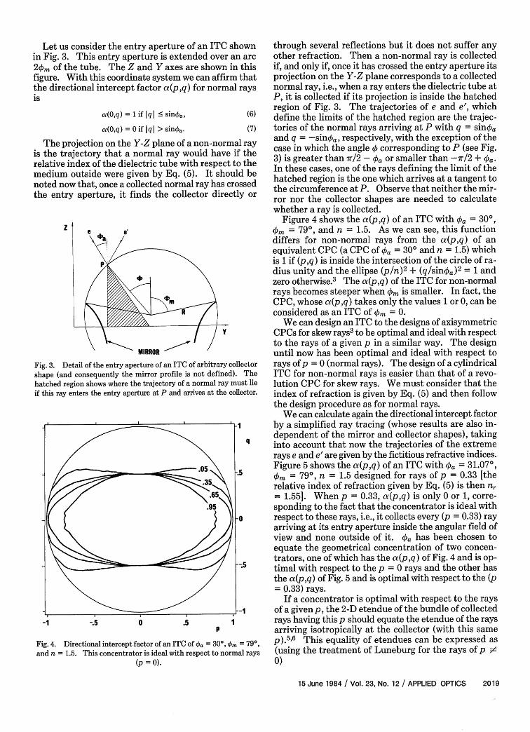
Fig. 4. Directional intercept factor of an ITC of ka = 30°, 'km = 79°,and n = 1.5. This concentrator is ideal with respect to normal rays
(p =0).
through several reflections but it does not suffer anyother refraction. Then a non-normal ray is collectedif, and only if, once it has crossed the entry aperture itsprojection on the Y-Z plane corresponds to a collectednormal ray, i.e., when a ray enters the dielectric tube atP, it is collected if its projection is inside the hatchedregion of Fig. 3. The trajectories of e and e', whichdefine the limits of the hatched region are the trajec-tories of the normal rays arriving at P with q = sinkaand q = -sinoa, respectively, with the exception of thecase in which the angle q corresponding to P (see Fig.3) is greater than r/2 - a or smaller than -7r/2 + 'ka.In these cases, one of the rays defining the limit of thehatched region is the one which arrives at a tangent tothe circumference at P. Observe that neither the mir-ror nor the collector shapes are needed to calculatewhether a ray is collected.
Figure 4 shows the a(pq) of an ITC with Oa = 300,'km = 790, and n = 1.5. As we can see, this functiondiffers for non-normal rays from the a(p,q) of anequivalent CPC (a CPC of pa = 30° and n = 1.5) whichis 1 if (p ,q) is inside the intersection of the circle of ra-dius unity and the ellipse (p/n) 2
+ (q/sinka)2= 1 and
zero otherwise.3 The Of(pq) of the ITC for non-normalrays becomes steeper when 'km is smaller. In fact, theCPC, whose a(p,q) takes only the values 1 or 0, can beconsidered as an ITC of </nm = 0.
We can design an ITC to the designs of axisymmetricCPCs for skew rays3 to be optimal and ideal with respectto the rays of a given p in a similar way. The designuntil now has been optimal and ideal with respect torays of p = 0 (normal rays). The design of a cylindricalITC for non-normal rays is easier than that of a revo-lution CPC for skew rays. We must consider that theindex of refraction is given by Eq. (5) and then followthe design procedure as for normal rays.
We can calculate again the directional intercept factorby a simplified ray tracing (whose results are also in-dependent of the mirror and collector shapes), takinginto account that now the trajectories of the extremerays e and e' are given by the fictitious refractive indices.Figure 5 shows the d(p,q) of an ITC with Oka = 31.07°,'km = 790, n = 1.5 designed for rays of p = 0.33 [therelative index of refraction given by Eq. (5) is then nr= 1.55]. When p = 0.33, ca(p,q) is only 0 or 1, corre-sponding to the fact that the concentrator is ideal withrespect to these rays, i.e., it collects every (p = 0.33) rayarriving at its entry aperture inside the angular field ofview and none outside of it. Oa has been chosen toequate the geometrical concentration of two concen-trators, one of which has the a(p,q) of Fig. 4 and is op-timal with respect to the p = 0 rays and the other hasthe Of(p,q) of Fig. 5 and is optimal with respect to the (p= Q.33) rays.
If a concentrator is optimal with respect to the raysof a given p, the 2-D etendue of the bundle of collectedrays having this p should equate the etendue of the raysarriving isotropically at the collector (with this samep).
5,6 This equality of etendues can be expressed as
(using the treatment of Luneburg for the rays of p #d0)
15 June 1984 / Vol. 23, No. 12 / APPLIED OPTICS 2019

2R (¢0m + Ma - 2 + cos('. - a)J(1 - p2)1 /2 = 2(n2 -p
(8)
and so
2R [d0 + ka - - + cos(. - a)J = 2nAc, (9)
where R is the radius of the dielectric tube, nr is givenby Eq. (5), and Ac is the perimeter of the cross sectionof the collector (the angles in radians). The left-handside of Eq. (8) is the etendue of the bundle of raysreaching the entry aperture with I ( < ka if this entryaperture is extended over an arc 'km Ž r/2 - a (seeFig. 3).2 Otherwise, which is not our case, Eqs. (8) and(9) are not valid. Since the geometrical concentrationCg is 2mR/Ac, we can express Eq. (9) as
C 0. + 'ka _ 2 + cOs(O. _ 'a)] = 2lr.(10)
Cg can be obtained using Eq. (10) (Cg = 4.19) for theconcentrator corresponding to Fig. 4 (in this case n =n). Then, the same equation can be solved to obtainthe 'a which corresponds to Fig. 5. When the collectoris bifacial we should consider that Ac is the area of thetwo faces.
Another parameter which gives useful informationabout the concentrators is the degree of isotropy g.7 Todefine g, let us assume that each point on the collectorsurface is radiating isotropically. The degree of isot-ropy can be defined as the fraction of power radiated bythe collector not given back by the concentrator. Notethat it would be desirable to have g = 1, since each rayturned back to the collector links two points of the col-lector surface and so the possibility of receiving energyfrom the source at these two points through these raysis avoided.
The degrees of isotropy of the concentrators corre-sponding to Figs. 4 and 5 are, respectively, 0.685 and0.697. Knowing Cg and n, it could be previewed thatg < 0.77 because of the cylindrical structure of theseconcentrators.7 This upper limit of g is achieved by acylindrical CPC of equal Cg and n.
Now we are tempted to design a cylindrical CPC tobe optimal and ideal for rays of p sd 0, as we have donefor the ITC. We found that with the same Cg and n, theCPC designed for non-normal rays is identical to theCPC designed for normal rays, i.e., even when designingfor non-normal rays, the standard CPC solution fornormal rays is the best that can be done.
IV. Conclusions
We have studied the cylindrical optical system as alimit case of the toroidal optical system, when the wholesystem is infinitely far from the axis of symmetry. Ourinterest was focused on cylindrical nonimaging con-centrators.
From this point of view, the non-normal rays of acylindrical structure are derived from the skew rays ofan axisymmetrical one. This enables us to apply thetreatment developed by Luneburg for skew rays to the
q
i ;5~~~~~~~~~~~~~9
I 0
-.5
-1 -.5 0 .5 1p
Fig. 5. Directional intercept factor of an ITC of 0 = 31.07°, 'k =790, and n = 1.5. This concentrator is ideal with respect to rays of
p = 0.33.
non-normal rays, which is helpful for concentrator raytracing purposes. As a result we learn that a non-nor-mal ray can be treated as if it were a normal ray tra-versing the same device but with modified indices ofrefraction.
These results have been used to calculate the direc-tional intercept factor of ITCs and in the design of ITCsthat behave as optimal and ideal concentrators withrespect to non-normal rays. We have also found thatthe standard CPC designed for normal rays is also op-timal and ideal with respect to any set of non-normalrays (of constant p). These results are independent ofthe collector and mirror profiles.
References1. R. K. Luneburg, Mathematical Theory of Optics (U. California
Press, Berkeley, 1964).2. J. C. Mifiano, J. M. Ruiz, and A. Luque, "Design of Optimal and
Ideal 2-D Concentrators with the Collector Immersed in a Di-electric Tube," Appl. Opt. 22, 3960 (1983).
3. W. T. Welford and R. Winston, Optics of Nonimaging Concen-trators (Academic, New York, 1978).
4. L. A. Whitehead, "Simplified Ray Tracing in Cylindrical Systems,"Appl. Opt. 21, 3536 (1982).
5. A. Luque, "Theoretical Bases of Photovoltaic Concentrators forExtended Light Sources," Sol. Cells 3, 355 (1981).
6. To calculate the etendue of a 2-D bundle of rays it is not necessarythat these rays be coplanar, as the rays of p = 0 are (a 2-D bundleof rays is the one formed by rays that can be distinguished betweenthem by giving two parameters, see Ref. 7).
7. J. C. Mifiano, "Application of the Conservation of Etendue The-orem for 2-D Subdomains of the Phase Space in NonimagingConcentrators," Appl. Opt. 23, 2021 (1984).
2020 APPLIED OPTICS / Vol. 23, No. 12 / 15 June 1984