d-a233 518 - defense technical information · pdf filed-a233 518 conspicuity ... community...
TRANSCRIPT

USAARL Report No. 91-9
D-A233 518
Conspicuity Comparison of Currentand Proposed U.S. Army Wire Marker Designs
By
Richard R. LevineClarence E. Rash
John S. Martin
Sensory Research Division
DTICS ELECTE
sMAR 2 7, 198vIFebruary 1991 B
Approved for public release; distribution unlimited.
91 s Z, 151United States Army Aeromedical Research Laboratory
Fort Rucker, Alabama 36362-5292
Notice
qualified requesters
Qualified requesters may obtain copies from the DefenseTechnical Information Center (DTIC), Cameron Station, Alexandria,Virginia 22314. Orders will be expedited if placed through thelibrarian or other person designated to request documents fromDTIC.
ChanQe of address
Organizations receiving reports from the U.S. ArmyAeromedical Research Laboratory on automatic mailing lists shouldconfirm correct address when corresponding about laboratoryreports.
Disposition
Destroy this report when it is no longer needed. Do not returnto the originator.
Disclaimer
The views, opinions, and/or findings contained in this reportare those of the authors and should not be construed as anofficial Department of the Army position, policy, or decision,unless so designated by other official documentatiun. Citdtionof trade names in this report does not constitute an officialDepartment of the Army endorsement or approval of the use of suchcommercial items.
Human use
Human subjects participated in these studies after givingtheir free and informed voluntary consent. Investigators adheredto AR 70-25 and USAMRDC Reg 70-25 on Use of Volunteers inResearch.
Review
THOMAS L. FREZELLLTC, MSDirector, Sensor esearch
io Released for publication:
ROG5 RW. WILEYO.D., Ph.D. DAVID H. KARNEChal an, Scientific Colonel, MC, S SReview Committee Commanding

Unclassified
REPORT DOCUMENTATION PAGE ,MR No 07 04 nl1a
a ,LT C 4,(,T> CASSF CATC. : R' $ i( VA N(C "-Unclassified
4a SECURiTY CLASSI- CATION AC.T-iRIT' 3 DSTRiBuTiON/AVAILABI'1YV OF REPORT
Approved for public release; distribution,b DECLASS;F'CATION /DOVVNGRADiNG SCHEDLE unlimited4 PERFORM!NG ORGANIZATION REPORT NuMBER(S) 5 MONITORING ORGANIZATION REPORT NUMBER(S)
USAARL Report No. 91-9
6a NAME OF PERFORMING ORGANIZATION 6b OFFICE SYMBOl 7a. NAME OF MONITORING ORGANIZATION
U.S. Army Aeromedical Research (If applicable) U.S. Army Medical Research and DevelopmentLaboratory SGRD-UAS-VS Command
6c ADDRESS Cjty, State, and ZIP Code) 7b ADDRESS (City, State, and ZIP Code)
Fort DetrickFort Pucker, AL 36362-5292 Frederick, MD 21702-5012
.*Z C7 SPUNSORIN(, 8b uFFICE SYMBOL 9 PROCUREMENT INSTRUMENT IDENTIFICATION NUMBERORGANIZATION (If applicable)
8c. ADDRESS (City, State, and ZIPCode) 10. SOURCE OF FUNDING NUMBERSPROGRAM PROJECT TASK WORK UNITELEMENT NO. NO. 3M1627 NO. ACCESSION NO.
62787A 87A879 BG 16411 TITLE (Include Security Classification)
Conspicuity Comparison of Current and Proposed U.S. Army Wire Marker Designs (U)
12 PERSONAL AUTHOR(S)
Richard R. Levine, Clarence E. Rash and John S. Martin3a TYPE OF REPORT 13b TIME COVERED 14. DATE OF REPORT (Year, Month, Day) 15. PAGE COUNTFinal FROM _ TO_ 1991 February 22
16 SUPPLEMENTARY NOTATION..
17 COSATI CODES 18 SUBJECT TERMS (Continue on reverse if necessary and identify by b* number)FED GROUP SUB-GROUP -+ night vision goggles (NVG), conspicuity, wire
06 marker4 wire strikes, visual detection.23 7)-
19 ABSTRACT (Continue on reverse if necessary and identify by block number)In-flight wire strikes are a serious threat to U.S. Army aviation during all-weather
daytime and nighttime helicopter operations. To reduce this threat, the aviation trainingcommunity employs a passive marking system for increasing the conspicuity of high tensioncables, electrical power lines, and telephone wires. This system uses international-orangefiberglass spheres having a diameter of approximately 11.5 inches and utilizing variousconspicuity enhancing schemes. These spheres are attached to the cables and wires atlocations heavily used by aircraft. In this study, the conspicuity of the basic and pro-posed modified designs was investigated as a function of background, illumination level(for both day and night with weather effects), sun (or other bright source) angle, andviewing system (e.g., unaided eye, thermal sensor, or image intensifier). While no differ-ences among designs were observed under daylight conditions, improved performance under
Continued
20 DISTRtBL ,N/AVAILABILITY OF ABSTRACT 21 ABSTOACT SECURITY r(L-tS',FICAT13N
-UNCLASSIFIED/UNLIMITED ] SAME t' RPT rj ,TiC uERS Unlc la ,sified;, ;A:,E Q ;, L" ;d: vIDUAL I 22b TELEPHONE (Include Area Code) 22r. OFFICE SYMBOLChief, Scientific Information Center (205) 255-6907 1 SGRD-UAX-SI
DD Form 1473, JUN 86 Previous editions are obsolete. SECURITY CLASSIFICATION OF THIS PAGEUnclassified

19. ABSTRACT (Continued)several viewing/lighting conditions was observed for two retroreflectivepolyhedron designs under typical aircraft lighting conditions at night.Increased detection ranges were noted both with and without imaqeintensification devices and under aircraft lighting conditions charac-teristic of the local aviation training environment.
Acknowledgments
The authors would like to extend their appreciation to thefollowing individuals who assisted in this study: LTC TomFrezell, LTC Roy Hancock, and CPT Mike Hulsey, who served asaviators; SGT Clint Shirley, SGT Jim Bohling, Mr. Simon Grase,PVT Gerry Polakis, SPC Judy Bielawski, and Mr. Everett McGowinIII, who provided technical support; SFC Doug Pritts and SPCRobert Hines, who served as crew chiefs; CW2 M. Manuel and CPTRon Wilson, who served as liaisons between USAARL and theAviation Training Battalion.
Accession For
NTIS GRA&IDTIC TAB 0Unannounced 0]Justification . -
By____________
Distribution/
AvailabilitY Codes
Avail and/or;.Dist special
FLlN. '
m .|I~m~iinl| II I
This page intentionally left blank.
ii
Table of contents
List of figures................................................ 2
List of tables................................................. 2
Introduction................................................... 3
Methods........................................................ 5
Subjects.................................................. 5
Wire markers.............................................. 5
Procedure................................................. 7
Results........................................................ 11
Daylight trials........................................... 11
Night trials.............................................. 11
Discussion..................................................... 16
Recommendations................................................ 17
References..................................................... 19
Appendixes
Appendix A - Absolute and relative difference indetection range: AN/PVS-5,vs. unaidedviewing..................................... 20
Appendix B - Absolute and relative differences indetection range: AI4VIS vs. unaided viewing.. 21
Appendix C - Absolute and relative differences indetection range: ANVIS vs. AN/PVS-5 .......... 22

List of figures
1. Current wire marker, international orange sphere ......... 4
2. Marker enhancements include: (a) white reflective tapein cross-pattern (loft) and (b) proposed polyhedron de-sign with circular patterns of retroreflective sheetingmaterial (right) .......................................... 4
3. Wire marker test designs: (a) uniform sphere; (b) spherewith light reflective tape in a cross (X) design; (c)uniform polyhedron; (d) polyhedron with circular pat-terns of white retroreflective sheeting; and (e) poly-hydron with circular patterns of yellow retroreflectivesheeting .................................................. 5
4. Wire marker mounted on pole .............................. 6
5. Schematic drawing of test field .......................... 6
6. Subject seating in UH-I test aircraft ................... 9
List of tables
1. Test design matrix ........................................ 8
2. Mean (and standard deviation) detection rangesunder daylight conditions (in feet) ..................... 12
3. Mean (and standard deviation) detection rangesunder nighttime conditions: Unaided viewing (infeet; N=8/condition) ..................................... 12
4. Mean (and standard deviation) detection rangesunder nighttime conditions: AN/PVS-5 viewing (infeet; N=4/condition) ..................................... 13
5. Mean (and standard deviation) detection rangesunder nighttime conditions: ANVIS viewing (in feet;N=4/condition) ........................................... 13
6. Range increases (increase factors) among wire markersrelative to the current Army design (Marker 1) .......... 15
7. Summary of daytime/nighttime mean detection ranges ...... 16
2
Introduction
In-flight wire strikes are a serious threat to U.S. Armyaviation during all-weather daytime and nighttime helicopteroperations, including: terrain flight, enclosed area takeoff andlanding, and confined area maneuvering. Despite training on wireavoidance techniques, peacetime wire strikes and the resultantloss of aircraft and life remain a serious problem. Previousinvestigations of rotary wing wire strike accidents for theperiods of 1958-1965 (U. S. Army Aviation Materiel Laboratories,1966), June 1966-June 1970 (Christian and Kuhns, 1971), July1972-July 1976 (Mynard, 1977), and January 1974-August 1981(Posey, et al., 1989) have shown a total of 553 wire strikes,resulting in 118 fatalities, and damage in excess of $40 million(these figures do not include the U.S. flying experience inVietnam). Wire strike data since 1981 have not been tabulated.Inasmuch as a majority of mishaps have occurred during trainingand over familiar sites, it can be assumed the wire impact threatposed by combat operations in unfamiliar areas will increase.
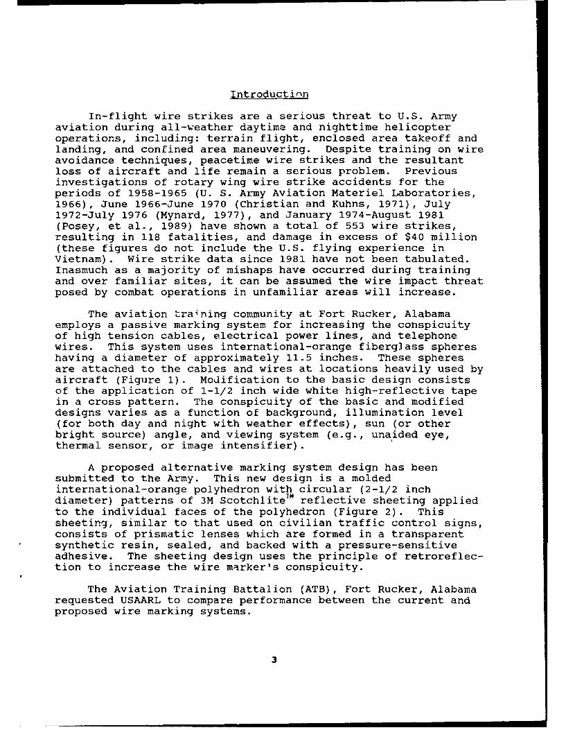
The aviation training community at Fort Rucker, Alabamaemploys a passive marking system for increasing the conspicuityof high tension cables, electrical power lines, and telephonewires. This system uses international-orange fiberglass sphereshaving a diameter of approximately 11.5 inches. These spheresare attached to the cables and wires at locations heavily used byaircraft (Figure 1). Modification to the basic design consistsof the application of 1-1/2 inch wide white high-reflective tapein a cross pattern. The conspicuity of the basic and modifieddesigns varies as a function of background, illumination level(for both day and night with weather effects), sun (or otherbright source) angle, and viewing system (e.g., unaided eye,thermal sensor, or image intensifier).
A proposed alternative marking system design has beensubmitted to the Army. This new design is a moldedinternational-orange polyhedron with circular (2-1/2 inchdiameter) patterns of 3M Scotchlite Tm reflective sheeting appliedto the individual faces of the polyhedron (Figure 2). Thissheeting, similar to that used on civilian traffic control signs,consists of prismatic lenses which are formed in a transparentsynthetic resin, sealed, and backed with a pressure-sensitiveadhesive. The sheeting design uses the principle of retroreflec-tion to increase the wire marker's conspicuity.
The Aviation Training Battalion (ATB), Fort Rucker, Alabamarequested USAARL to compare performance between the current andproposed wire marking systems.
3
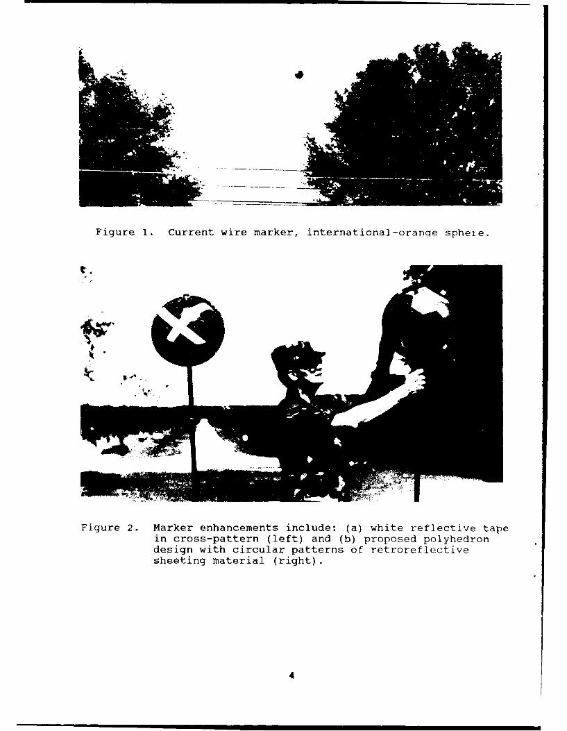
Figure 1. Current wire marker, international-orange sphere.
Figure 2. Marker enhancements include: (a) white reflective tapein cross-pattern (left) and (b) proposed polyhedrondesign with circular patterns of retroreflectivesheeting material (right).
4

Methods
Subjects
Sixteen volunteer subjects, aged from 19-33 (average =
24.8), participated in the study. All participants were warrantofficer candidates awaiting the start of helicopter flighttraining. All had passed the Army's Class I flight physicalrequiring at least 20/20 or better uncorrected Snellen acuity andnormal color vision. Four subjects served as aeroscout observers(military occupational specialty 93B) and had previous experiencewith the AN/PVS-5 night vision goggle. The remaining subjectshad no previous helicopter flight time or goggle experien2e.
Wire markers
Five wire marker designs, all international-orange in color,were tested. The designs were: I) uniform sphere, (2) spherewith white reflective tape in a cross (X) pattern, (3) uniformpolyhedron, (4) polyhedron wit' circular patterns of whiteretroreflective sheeting, and k5) polyhedron with circularpatterns of yellow retrorefle .tive sheeting. Each of thepolyhedrons were of the same shape with flat polygonal faces ontheir outer surfaces. The designs included the two basic design
(a) (b) (c) (d) (e)
Figure 3. Wire marker test designs: (a) uniform sphere, (b)sphere with light reflective tape in a cross (X)design, (c) uniform polyhedron, (d) polyhedron withcircular patterns of white retroreflective sheeting,(e) polyhedron with circular patterns of yellow retro-reflective sheeting.
5

Figure 4. Wire marker mounted on pole.
4 1) ft 1 t da
40 ft
85o ft
white4 ft by4 ff'K,, 45 0angle
30 3 ft
A v
1000 It
1100 ft
Figure 5. Schematic drawing of test field.
6

geometries (markers 1,3) and enhanced (reflective) versions ofeach (markers 2,4,5). The markers, shown in Figure 3, wereprovided by ATB.
Procedure
The study was conducted in two phases at Skelly stagefieldnear Opp, Alabama. In the first phase, the conspicuity of thewire marker designs was investigated under clear and sunnydaytime conditions for the unaided eye with both the clear (class1) and tinted (class 2) SPH-4 visors. Testing was accomplishedfor two sun angles representing the positions of oblique morning(0800-0900 hours) and overhead afternoon (1300-1400 hours) light.The second phase was conducted at night (2100-2400) for theunaided eye and with the AN/PVS-5 Night Vision Goggles (NVG) andthe Aviator's Night Vision Imaging System (ANVIS) image intensi-fication systems. Each nighttime viewing condition was testedunder a number of different aircraft lighting conditions (seebelow). Nighttime trials were conducted under clear weather andlunar conditions of altitude greater than 30 degrees and fractionof illumination greater than 23 percent. A matrix of all theconditions tested is shown in Table 1.
In bo h phases, the wire markers were mounted on 10-footpoles located at the southern end of the stagefield (Figure 4); atree line located behind the markers served as a relativelyuniform, unstructured background. In the daytime, the poles werearranged in a single row at separation distances of 85 feet; atnight, the distance between the poles was reduced to 50 feet. Apair of 4 X 4 foot wood panels, painted white and angled 45degrees, were each positioned, in line, 40 feet and 70 feet,respectively, in front of each pole. These were used as lanemarkers to assist the subjects in identifying the targetpositions from the aircraft (see below). (At night, chemicallight sticks were hung over each panel to facilitate identifyingtheir location.) From the center pole, a series of automobiletires, painted white, were placed at intervals of 100 feet out toa distance of 4200 feet (the maximum available working range ofthe stagefield). These served both as observation points for thesubjects viewing the markers and as references points for thepilots flying the aircraft. A schematic drawing of the testfield is shown in Figure 5.
The subjects viewed the markers while seated sideways ineither the left or right rear seats of the UH-l helicopter.Subjects were tested four at a time, two on each side of theaircraft (Seats 3 and 6 on the right and Seats 2 and 5 on theleft as shown in the UH-1 alternate seating plan [Department ofthe Army Technical Manual 55-1520-210-10] (Figure 6). Duringtesting, the aircraft was maintained at a low hover (10-20 feetabove ground level (AGL)) and subjects viewed downrange via the
7
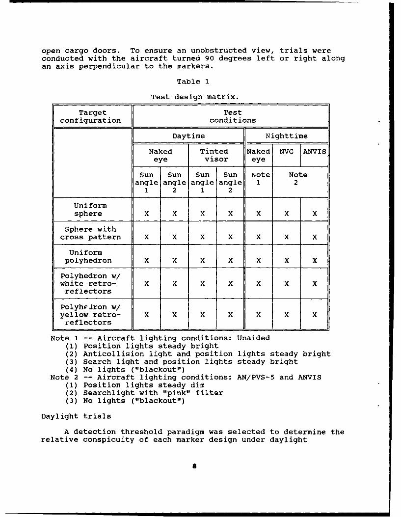
open cargo doors. To ensure an unobstructed view, trials wereconducted with the aircraft turned 90 degrees left or right alongan axis perpendicular to the markers.
Table 1
Test design matrix.
Target Testconfiguration conditions
Daytime Nighttime
Naked Tinted Naked NVG ANVISeye visor eye
Sun Sun Sun Sun Note Noteangle angle angle angle 1 2
1 2 1 2
Uniformsphere X X X X X X X
Sphere withcross pattern X X X X X X X
Uniformpolyhedron X X X X X X X
Polyhedron w/white retro- X X X X X X Xreflectors
Polyh Jron w/yellow retro- X X X X X X Xreflectors
Note 1 -- Aircraft lighting conditions: Unaided(1) Position lights steady bright(2) Anticollision light and position lights steady bright(3) Search light and position lights steady bright(4) No lights ("blackout")
Note 2 -- Aircraft lighting conditions: AN/PVS-5 and ANVIS(1) Position lights steady dim(2) Searchlight with "pink" filter(3) No lights ("blackout")
Daylight trials
A detection threshold paradigm was selected to determine therelative conspicuity of each marker design under daylight
S
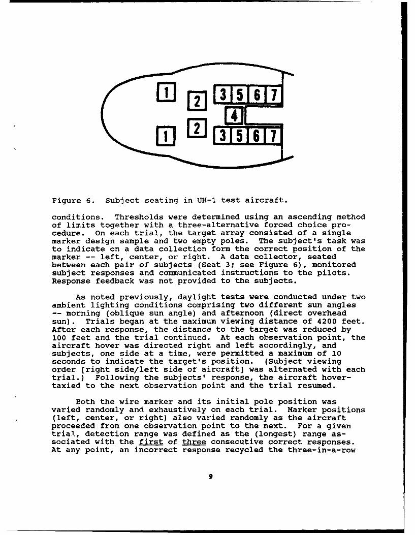
Figure 6. Subject seating in UH-l test aircraft.
conditions. Thresholds were determined using an ascending methodof limits together with a three-alternative forced choice pro-cedure. On each trial, the target array consisted of a singlemarker design sample and two empty poles. The subject's task wasto indicate on a data collection form the correct position of themarker -- left, center, or right. A data collector, seatedbetween each pair of subjects (Seat 3; see Figure 6), monitoredsubject responses and communicated instructions to the pilots.Response feedback was not provided to the subjects.
As noted previously, daylight tests were conducted under twoambient lighting conditions comprising two different sun angles-- morning (oblique sun angle) and afternoon (direct overheadsun). Trials began at the maximum viewing distance of 4200 feet.After each response, the distance to the target was reduced by100 feet and the trial continued. At each observation point, theaircraft hover was directed right and left accordingly, andsubjects, one side at a time, were permitted a maximum of 10seconds to indicate the target's position. (Subject viewingorder [right side/left side of aircraft] was alternated with eachtrial.) Following the subjects' response, the aircraft hover-taxied to the next observation point and the trial resumed.
Both the wire marker and its initial pole position wasvaried randomly and exhaustively on each trial. Marker positions(left, center, or right) also varied randomly as the aircraftproceeded from one observation point to the next. For a giventrial, detection range was defined as the (longest) range as-sociated with the first of three consecutive correct responses.At any point, an incorrect response recycled the three-in-a-row
9

correct response criterion. Three trials were run for eachmarker design, yielding a total of 30 trials (15 per sun angle)for each subject. For each marker, the subject's overalldetection range was calculated as the average of the threetrials.
Testing for each subject was conducted over a 2-day period.On the morning of day-l, two subjects were tested with each visor-- clear or tinted. Visors then were switched among the subjectsfor the afternoon run. On day-2, visor wear was reversed.Subjects wearing either clear or tinted visors on the previousmorning's test now wore the opposite visor on the morning of day-2. The visors were then reversed again on the afternoon of day-2. A total of four subjects were tested under each visor/sunangle condition except for the tinted visor under sun angle 1 inwhich three subjects were tested.
Nighttime trials
Because of the reduced ranges associated with low-lightviewing (for both pilots and subjects), several of the daytimetest procedures were modified to enhance safety of flight.First, a modified descending method of limits was used todetermine detection threshold. Second, observations began at adistance where the marker was known to be visible (under someviewing conditions, as close as 100 feet). Third, only two ofthe poles (marker lanes) -- center and right -- were used. Thegeneral procedure was as follows: On each trial, the test markerappeared on the right pole (from the subject's perspective) whilea standard, comparison marker (the polyhedron with yellow reflec-tive sheeting) appeared in the center. (During preliminarytesting, this latter marker had the longest naked eye detectionrange. During actual testing, it was used primarily to orientthe subjects gaze toward the test area. In addition, itsidentity remained unknown to the subjects and its thresholddetection range was determined only while situated in the right[test] lane.) The subject's task consisted of indicating whetherthe right, left, both, or neither of the markers were visible.As before, succeeding observations were made at 100-footintervals. However, instead of approaching the target, theaircraft moved away from the target with each observation.Detection threshold for each design was defined as the lastdistance at which the marker was reported visible. Because ofthe reduced pace of testing at night, only one trial per subjectwas run for each viewing/lighting combination.
As shown in Table 1, each viewing mode was run under severaldifferent aircraft lighting schemes. For unaided viewing,testing was conducted under four aircraft lighting conditions,including: (1) position ("running") lights steady bright;
10
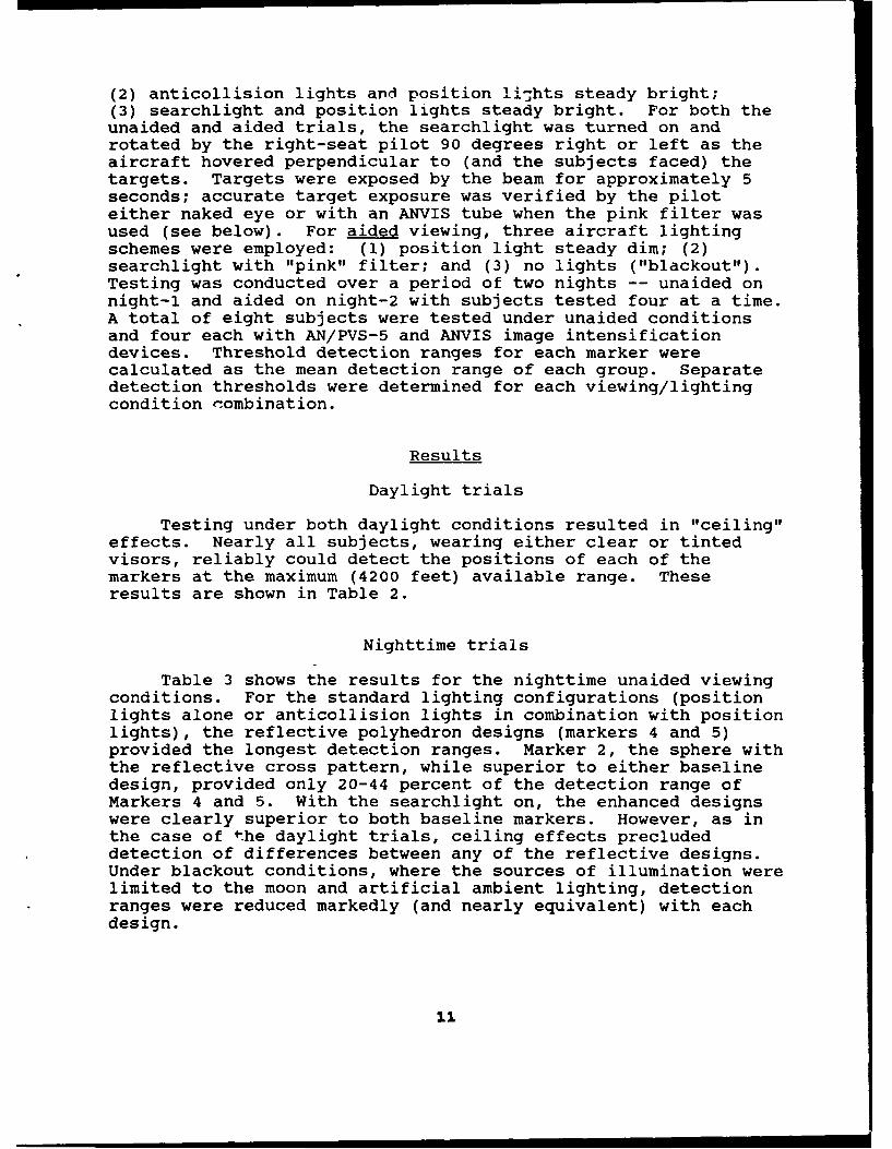
(2) anticollision lights and position lights steady bright;(3) searchlight and position lights steady bright. For both theunaided and aided trials, the searchlight was turned on androtated by the right-seat pilot 90 degrees right or left as theaircraft hovered perpendicular to (and the subjects faced) thetargets. Targets were exposed by the beam for approximately 5seconds; accurate target exposure was verified by the piloteither naked eye or with an ANVIS tube when the pink filter wasused (see below). For aided viewing, three aircraft lightingschemes were employed: (1) position light steady dim; (2)searchlight with "pink" filter; and (3) no lights ("blackout").Testing was conducted over a period of two nights -- unaided onnight-i and aided on night-2 with subjects tested four at a time.A total of eight subjects were tested under unaided conditionsand four each with AN/PVS-5 and ANVIS image intensificationdevices. Threshold detection ranges for each marker werecalculated as the mean detection range of each group. Separatedetection thresholds were determined for each viewing/lightingcondition combination.
Results
Daylight trials
Testing under both daylight conditions resulted in "ceiling"effects. Nearly all subjects, wearing either clear or tintedvisors, reliably could detect the positions of each of themarkers at the maximum (4200 feet) available range. Theseresults are shown in Table 2.
Nighttime trials
Table 3 shows the results for the nighttime unaided viewingconditions. For the standard lighting configurations (positionlights alone or anticollision lights in combination with positionlights), the reflective polyhedron designs (markers 4 and 5)provided the longest detection ranges. Marker 2, the sphere withthe reflective cross pattern, while superior to either baselinedesign, provided only 20-44 percent of the detection range ofMarkers 4 and 5. With the searchlight on, the enhanced designswere clearly superior to both baseline markers. However, as inthe case of the daylight trials, ceiling effects precludeddetection of differences between any of the reflective designs.Under blackout conditions, where the sources of illumination werelimited to the moon and artificial ambient lighting, detectionranges were reduced markedly (and nearly equivalent) with eachdesign.
11

Table 2
Mean (and standard deviation) detection rangesunder daylight conditions (in feet).
Sun angle 1 Sun angle 2Wire
marker* Clear visor Tinted visor Clear visor Tinted visorN=4 N=3 N=4 N=4
1 4200 4189 4175 4150
(0) (20) (50) (58)
2 4200 4167 4200 4200
(0) (58) (0) (0)
3 4200 4200 4200 4200
(0) (0) (0) (0)
4 4200 4200 4200 4200(0) (0) (0) (0)
5 4200 4200 4200 4200
(0) (0) (0) (0)
Table 3
Mean (and standard deviation) detection rangesunder nighttime conditions: Unaided viewing
(in feet; N=8/condition).
Wire Position Anticollision Searchlight Blackoutmarker* lights lights
1 125 213 1200 63(83) (60) (112) (70)
2 488 688 4200 125(60) (60) (0) (43)
3 138 213 1313 63(48) (60) (136) (48)
4 750 1163 4200 138(71) (132) (0) (48)
5 613 1225 4200 88(78) (139) (0) (33)
* (For all tables). Marker 1: Uniform sphereMarker 2: Sphere with reflective tapeMarker 3: Uniform polyhedronMarker 4: Polyhedron with white reflective sheetingMarker 5: Polyhedron with yellow reflective sheeting
12
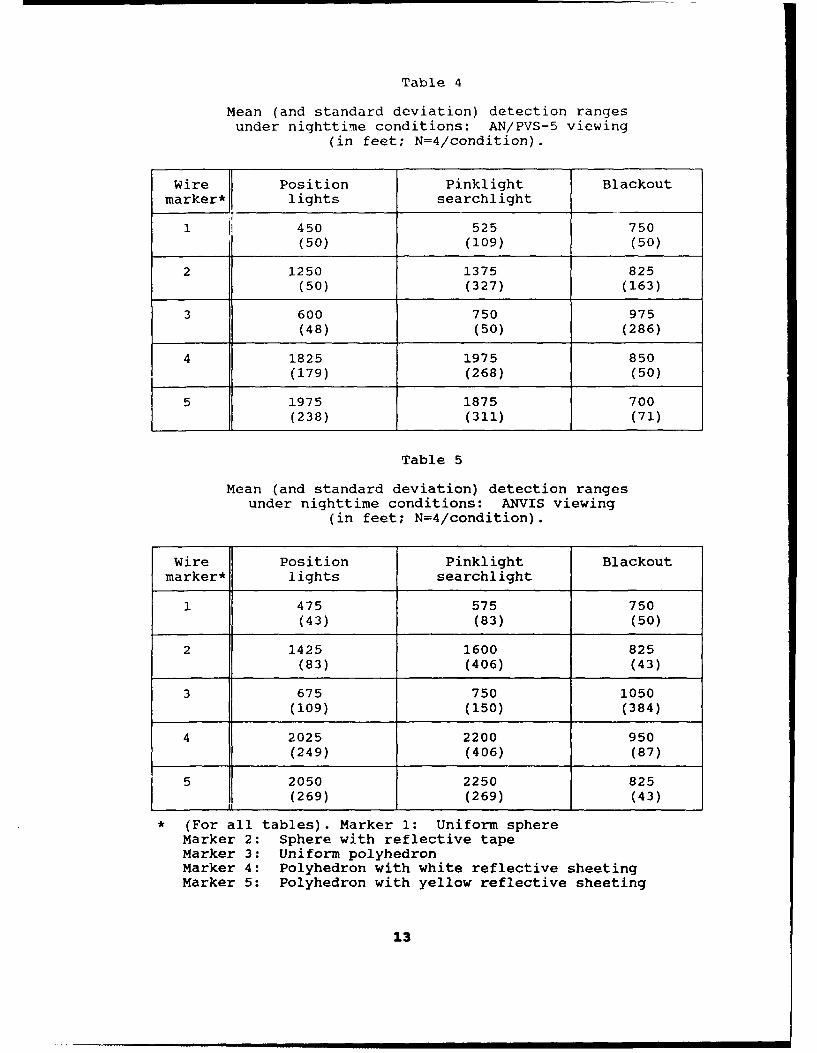
Table 4
Mean (and standard deviation) detection rangesunder nighttime conditions: AN/PVS-5 viewing
(in feet; N=4/condition).
Wire Position Pinklight Blackoutmarker* lights searchlight
1 450 525 750(50) (109) (50)
2 1250 1375 825(50) (327) (163)
3 600 750 975(48) (50) (286)
4 1825 1975 850(179) (268) (50)
5 1975 1875 700(238) (311) (71)
Table 5
Mean (and standard deviation) detection rangesunder nighttime conditions: ANVIS viewing
(in feet; N=4/condition).
Wire Position Pinklight Blackoutmarker* lights searchlight
1 475 575 750(43) (83) (50)
2 1425 1600 825(83) (406) (43)
3 675 750 1050(109) (150) (384)
4 2025 2200 950(249) (406) (87)
5 2050 2250 825(269) (269) (43)
* (For all tables). Marker 1: Uniform sphere
Marker 2: Sphere with reflective tapeMarker 3: Uniform polyhedronMarker 4: Polyhedron with white reflective sheetingMarker 5: Polyhedron with yellow reflective sheeting
13
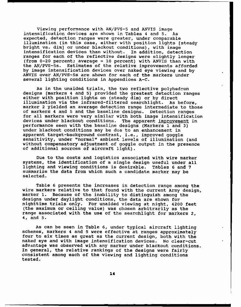
Viewing performance with AN/PVS-5 and ANVIS imageintensification devices are shown in Tables 4 and 5. Asexpected, detection ranges were greater, under comparableillumination (in this case, either with position lights [steadybright vs. dim] or under blackout conditions), with imageintensification devices than without. In addition, detectionranges for each of the reflective designs were slightly longer(from 0-20 percent; average = 10 percent) with ANVIS than withthe AN/PVS-5s. Estimates of the relative improvements affordedby image intensification devices over naked eye viewing and byANVIS over AN/PVS-5s are shown for each of the markers underseveral lighting conditions in Appendices A-C.
As in the unaided trials, the two reflective polyhedrondesigns (markers 4 and 5) provided the greatest detection rangeseither with position lights on (steady dim) or by directillumination via the infrared-filtered searchlight. As before,marker 2 yielded an average detection range intermediate to thoseof markers 4 and 5 and the baseline designs. Detection rangesfor all markers were very similar with both image intensificationdevices under blackout conditions. The apparent improvement inperformance seen with the baseline designs (Markers 1 and 3)under blackout conditions may be due to an enhancement inapparent target-background contrast, i.e., improved gogglesensitivity, under "normal" ambient levels of illumination (andwithout compensatory adjustment of goggle output in the presenceof additional sources of aircraft light).
Due to the costs and logistics associated with wire markersystems, the identification of a single design useful under alllighting and viewing conditions is desirable. Tables 6 and 7summarize the data from which such a candidate marker may beselected.
Table 6 presents the increases in detection range among thewire markers relative to that found with the current Army design,marker 1. Because of the inability to distinguish among thedesigns under daylight conditions, the data are shown fornighttime trials only. For unaided viewing at night, 4200 feet(the maximum or ceiling value) was chosen arbitrarily as therange associated with the use of the searchlight for markers 2,4, and 5.
As can be seen in Table 6, under typical aircraft lightingschemes, markers 4 and 5 were effective at ranges approximatelyfour to six times as great as the current design, both with thenaked eye and with image intensification devices. No clear-cutadvantage was observed with any marker under blackout conditions.In general, the relative rankings of the designs were fairlyconsistent among each of the viewing and lighting conditionstested.
14

Table 6
Range increases (increase factors) among wire markersrelative to the current Army design (marker 1).
Nighttime: Unaided
Wire Position Anticollision Searchlight Blackout
marker* lights lights
2 3.9 3.2 3.5 2.0
3 1.1 1.0 1.1 1.0
4 6.0 5.5 3.5 2.2
5 4.9 5.8 3.5 1.4
Nighttime: AN/PVS-5
Wire Position Pinklight Blackoutmarker lights searchlight
2 2.8 2.6 1.1
3 1.3 1.4 1.3
4 4.1 3.8 1.1
5 4.4 3.6 0.9
Nighttime: ANVIS
Wire Position Pinklight Blackoutmarker lights searchlight
1
2 3.0 2.8 1.1
3 1.4 1.3 1.4
4 4.3 3.8 1.3
5 4.3 3.9 1.1
* Marker 1: Uniform sphereMarker 2: Sphere with reflective tapeMarker 3: Uniform polyhedronMarker 4: Polyhedron with white reflective sheetingMarker 5: Polyhedron with yellow reflective sheeting
15
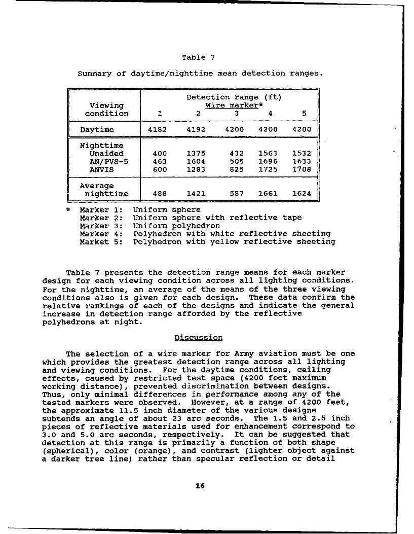
Table 7
Summary of daytime/nighttime mean detection ranges.
Detection range (ft)Viewing Wire marker*condition 1 2 3 4 5
Daytime 4182 4192 4200 4200 4200
NighttimeUnaided 400 1375 432 1563 1532AN/PVS-5 463 1604 505 1696 1633ANVIS 600 1283 825 1725 1708
Averagenighttime 488 1421 587 1661 1624
* Marker 1: Uniform sphereMarker 2: Uniform sphere with reflective tapeMarker 3: Uniform polyhedronMarker 4: Polyhedron with white reflective sheetingMarket 5: Polyhedron with yellow reflective sheeting
Table 7 presents the detection range means for each markerdesign for each viewing condition across all lighting conditions.For the nighttime, an average of the means of the three viewingconditions also is given for each design. These data confirm therelative rankings of each of the designs and indicate the generalincrease in detection range afforded by the reflectivepolyhedrons at night.
Discussion
The selection of a wire marker for Army aviation must be onewhich provides the greatest detection range across all lightingand viewing conditions. For the daytime conditions, ceilingeffects, caused by restricted test space (4200 foot maximumworking distance), prevented discrimination between designs.Thus, only minimal differences in performance among any of thetested markers were observed. However, at a range of 4200 feet,the approximate 11.5 inch diameter of the various designssubtends an angle of about 23 arc seconds. The 1.5 and 2.5 inchpieces of reflective materials used for enhancement correspond to3.0 and 5.0 arc seconds, respectively. It can be suggested thatdetection at this range is primarily a function of both shape(spherical), color (orange), and contrast (lighter object againsta darker tree line) rather than specular reflection or detail
16

within the shape. Therefore, it is unlikely that differences indetection range between any of the designs would be obtained atgreater observation ranges. (However, differences inconspicuity, and, hence, dete-tion range, could result fromdifferences in specular reflectivity with more mobile targets orviewing from a more mobile platform.)
Three viewing systems are used for night flight, i.e., theunaided eye, the AN/PVS-5 night vision goggle, and the ANVIS.Each of these systems has a different spectral response andsensitivity. With all of these systems, the detection range ofthe various designs depends on the level of light, the spectraldistribution of the ambient lighting, and the spectral reflectiveproperties of the markers.
For unaided viewing in the presence of artificial lightingin the form of position and anticollision lights, the threedesigns using reflective material provided the greatest detectionranges with markers 4 and 5 providing nearly twice the range ofmarker 2. Under the increased directional output provided by thesearchlight, a ceiling effect prevented discrimination betweenthe three reflective designs -- all three designs were equallydetectable out to the maximum test range of 4200 feet. Underblackout conditions, with moonlight as the principal source ofillumination, detectability among designs was considerablyreduced and nearly equivalent.
Similar trends in the data were observed with imageintensification devices, either AN/PVS-5's or ANVIS. With theaircraft's position lights on steady dim or illuminated with the"pinklight" searchlight, detection ranges with theretroreflective polyhedrons were generally superior to the otherdesigns. (As expected, the greater sensitivity afforded by ANVISresulted in uniformly increased detection ranges.) Under normallow-light ambient conditions ("blackout"), no significantadvantage in detectability was observed among any of the testeddesigns.
Recommendations
The results of this study demonstrate both viewing- andlighting-specific effects for each of the marker designs tested.While no differences among designs were observed under daylightconditions, improved performance under several viewing/lightingconditions was observed for both retroreflective polyhedrons(Markers 4 and 5) under typical aircraft lighting conditions atnight. Increased detection ranges were noted both with andwithout image intensification devices and under aircraft lightingconditions characteristic of the local aviation trainingenvironment. It should be emphasized that, because of the benignand relatively static conditions under which the data were
17

collected, it may be erroneous to use the ranges in the datatables as typical detection distances under training oroperational conditions. Nor should these data be used inconjunction with typical airspeeds to derive putative aviatorreaction times in field situations where search behavior isrequired. However, our data indicate that the reflectivepolyhedrons (markers 4 and 5) should provide relatively greaterconspicuity, and hence a greater margin of operator and trainingsafety, than designs (markers 1 and 2) currently in use.
18
References
Christian, W. P., and Kuhns, A.W. TS71. Wire strike mishapanalysis report. Fort Rucker, AT.: U.S. Army Board forAviation Accident Research. USABAAR Report No. 71-2.
Department of the Army. 1988. Operator's manual. Army ModelUH-IH/V helicopters. Washington, D.C.: Headquarters,Department of the Army. Technical Manual 55-1520-210-10.
Mynard, D. A. 1977. We can stop wire strikes. U. S. ArmyAviation Digest, February 1977; pp. 31-33.
Posey, D.M, Wagner, G.N., McMillin, S.E., Ruehle, C.J., Schell,B. E., and Pincho, R.J. 1989. Helicopter wire strikeaccident and high voltage electrocution: A case report.Aviation, Space, and Environmental Medicine, Vol. 60(10,Suppl.); pp. B29-34.
U.S. Army Board for Aviation Accident Research. 1966. Reportof wire strike accidents in Army aviation, 1 July 1957through 31 December J965. Fort Rucker, AL: USABAAR ReportApril 1966.
U.S. Army Aviation Materiel Laboratories. 1966. Investigationof low-level aircraft operational hazards. Fort Eustis, VA:USAAVLABS Technical Report No. 66-78.
19

Appendix A.
Absolute and relative differences -In detection range:AN/PVS-5 vs. unaided viewing.
Position lights* BlackoutWiremarker Absolute Relative Absolute Relative
difference** difference*** difference difference
1 325 3.6 687 12.0
2 762 2.6 700 6.6
3 1 462 4.4 912 15.6
4 1075 2.4 712 6.2
5 1362 3.2 612 8.0
*Low for AN/PVS-5; high for unaided viewing**Range 1A"VS-5 1-Range (Uoaidedl
***Range [AN/PS-5 1 /Range [Unakd
20

Appendix B.
Absolute and relative differences in detection range:ANVIS vs. unaided viewing.
Position lights* BlackoutWire
marker Absolute Relative Absolute Relativedifference** difference*** difference difference
1 350 3.8 687 12.0
2 937 2.9 700 6.6
3 537 4.9 987 16.8
4 1275 2.7 812 6.9
5 1427 3.3 737 9.4
* Low for ANVIS; high for unaided viewing** Range [ANVlIS-Range [Unadeq*** Range [ANVis]/Range [Unkkd]
21

Appendix C.
Absolute and relative differences in detection range:ANVIS vs. AN/PVS-5.
lgt*Searchlight BlackoutWire
marker Abs** Rel*** Abs Rel Abs Rel
4 200 1.11 225 1.11 100 1.12
575 1037 1.0 15 11
*Low intensity**Range 1AN1IS-Range (AN/PYS-6I
***Range ANV, 15 /Range (ANIPVS-51
22

Initial distribution
Commander, U.S. Army Natick Research, U.S. Army Avionics ResearchDevelopment and Evaluation Center and Development Activity
ATTN: STRNC-MIL (Documents ATTN: SAVAA-P-TPLibrarian) Fort Monmouth, NJ 07703-5401Natick, MA 01760-5040
U.S. Army Communications-ElectronicsNaval Submarine Medical Command
Research Laboratory ATI'N: AMSEL-RD-ESA-DMedical Library, Naval Sub Base Fort Monmouth, NJ 07703Box 900Groton, CT 06340 Library
Naval Submarine Medical Research LabCommander/Director Box 900, Naval Sub BaseU.S. Army Combat Surveillance Groton, CT 06349-5900
and Target Acquisition LabATTN: DELCS-D CommanderFort Monmouth, NJ 07703-5304 Man-Machine Integration System
Code 602Commander Naval Air Development Center10th Medical Laboratory Warminster, PA 18974ATTN: AudiologistAPO New York 09180 Commander
Naval Air Development CenterNaval Air Development Center A'TTN: Code 602-B (Mr. Brindle)Technical Information Division Warminster, PA 18974Technical Support DetachmentWarminster, PA 18974 Commanding Officer
Harry G. Armstrong AerospaceCommanding Officer, Naval Medical Medical Research Laboratory
Research and Development Command Wright-PattersonNational Naval Medical Center Air Force Base, OH 45433Bethesda, MD 20814-5044
DirectorDeputy Director, Defense Research Army Audiology and Speech Center
and Engineering Walter Reed Army Medical CenterATIT: Military Assistant Washington, DC 20307-5001
for Medical and Life SciencesWashington, DC 20301-3080 Commander, U.S. Army Institute
of Dental ResearchCommander, U.S. Army Research A'TTN: Jean A. Setterstrom, Ph. D.
Institute of Environmental Medicine Walter Reed Army Medical CenterNatick, MA 01760 Washington, DC 20307-5300
23

Naval Air Systems Command Naval Research LaboratoryTechnical Air Library 950D Library Code 1433Room 278, Jefferson Plaza II Washington, DC 20375Department of the NavyWashington, DC 20361 Harry Diamond Laboratories
ATTN: Technical Information BranchNaval Research Laboratory Library 2800 Powder Mill RoadShock and Vibration Adelphi, MD 20783-1197
Information Center, Code 5804Washington, DC 20375 U.S. Army Materiel Systems
Analysis AgencyDirector, U.S. Army Human ATTN: AMXSY-PA (Reports Processing)
Engineering Laboratory Aberdeen Proving GroundATTN: Technical Library MD 21005-5071Aberdeen Proving Ground, MD 21005
U.S. Army Ordnance CenterCommander, U.S. Army Test and School Library
and Evaluation Command Simpson Hall, Building 3071ATIN: AMSTE-AD-H Aberdeen Proving Ground, MD 21005Aberdeen Proving Ground, MD 21005
U.S. Army EnvironmentalDirector Hygiene AgencyU.S. Army Ballistic Building E2100
Research Laboratory Aberdeen Proving Ground, MD 21010ATTN: DRXBR-OD-ST Tech ReportsAberdeen Proving Ground, MD 21005 Technical Library Chemical Research
and Development CenterCommander Aberdeen Proving Ground, MDU.S. Army Medical Research 21010--5423
Institute of Chemical DefenseAITN: SGRD-UV-AO CommanderAberdeen Proving Ground, U.S. Army Medical ResearchMD 21010-5425 Institute of Infectious Disease
SGRD-UIZ-CCommander, U.S. Army Medical Fort Detrick, Frederick, MD 21702Research and Development CommandATTIN: SGRD-RMS (Ms. Madigan) Director, BiologicalFort Detrick, Frederick, MD 21702-5012 Sciences Division
Office of Naval ResearchDirector 600 North Quincy StreetWalter Reed Army Institute of Research Arlington, VA 22217Washington, DC 20307-5100
CommanderU.S. Army Materiel Command
HQ DA (DASG-PSP-O) AITN: AMCDE-XS5109 Leesburg Pike 5001 Eisenhower AvenueFalls Church, VA 22041-3258 Alexandria, VA 22333
24

Commandant CommanderU.S. Army Aviation U.S. Army Aviation Systems Command
Logistics School ATN: ATSQ-TDN ATTN: SGRD-UAX-AL (MAJ Gillette)Fort Eustis, VA 23604 4300 Goodfellow Blvd., Building 105
St. Louis, MO 63120Headquarters (ATMD)U.S. Army Training U.S. Army Aviation Systems Command
and Doctrine Command Library and Information Center BranchFort Monroe, VA 23651 ATTN: AMSAV-DIL
4300 Goodfellow BoulevardStructures Laboratory Library St. Louis, MO 63120USARTL-AVSCOMNASA Langley Research Center Federal Aviation AdministrationMail Stop 266 Civil Aeromedical InstituteHampton, VA 23665 Library AAM-400A
P.O. Box 25082Naval Aerospace Medical Oklahoma City, OK 73125
Institute LibraryBuilding 1953, Code 03L CommanderPensacola, FL 32508-5600 U.S. Army Academy
of Health SciencesCommand Surgeon ATIN: LibraryHQ USCENTCOM (CCSG) Fort Sam Houston, TX 78234U.S. Central CommandMacDill Air Force Base FL 33608 Commander
U.S. Army Institute of Surgical ResearchAir University Library ATTN: SGRD-USM (Jan Duke)(AUL/LSE) Fort Sam Houston, TX 78234-6200Maxwell Air Fore Base, AL 36112
AAMRL/HEXU.S. Air Force Institute Wright-Patterson
of Technology (AFIT/LDEE) Air Force Base, OH 45433Building 640, Area BWright-Patterson University of MichiganAir Force Base, OH 45433 NASA Center of Excellence in Man-
Systems ResearchHenry L. Taylor ATIN: R. G. Snyder, DirectorDirector, Institute of Aviation Ann Arbor, MI 48109University of Illinois-Willard AirportSavoy, IL 61874 John A. Dellinger,
Southwest Research InstituteChief, Nation Guard Bureau P. 0. Box 28510ATTN: NGB-ARS (COL Urbauer) San Antonio, TX 78284Room 410, Park Center 44501 Ford AvenueAlexandria, VA 22302-1451
25
Product Manager CommanderAviation Life Support Equipment Code 3431ATTN: AMCPM-ALSE Naval Weapons Center4300 Goodfellow Boulevard China Lake, CA 93555St. Louis, MO 63120-1798
Aeromechanics LaboratoryCommander U.S. Army Research and Technical LabsU.S. Army Aviation Ames Research Center, MIS 215-1
Systems Command Moffett Field, CA 94035ATTN: AMSAV-ED4300 Goodfellow Boulevard Sixth U.S. ArmySt. Louis, MO 63120 ATTN: SMA
Presidio of San Francisco, CA 94129Commanding OfficerNaval Biodynamics Laboratory CommanderP.O. Box 24907 U.S. Army Aeromedical CenterNew Orleans, LA 70189-0407 Fort Rucker, AL 36362
Assistant Commandant U.S. Air Force SchoolU.S. Army Field Artillery School of Aerospace MedicineATTN: Morris Swott Technical Library Strughold Aeromedical Library TechnicalFort Sill, OK 73503-0312 Reports Section (TSKD)
Brooks Air Force Base, TX 78235-5301CommanderU.S. Army Health Services Command Dr. Diane DamosATTN: HSOP-SO Department of Human FactorsFort Sam Houston, TX 78234-6000 ISSM, USC
Los Angeles, CA 90089-0021Director of Professional ServicesHQ USAF/SGDT U.S. Army White SandsBolling Air Force Base, DC 20332-6188 Missile Range
ATrN: STEWS-IM-STU.S. Army Dugway Proving Ground White Sands Missile Range, NM 88002Technical Library, Building 5330Dugway, UT 84022 U.S. Army Aviation Engineering
Flight ActivityU.S. Army Yuma Proving Ground ATTN: SAVTE-M (Tech Lib) Stop 217Technical Library Edwards Air Force Base, CA 93523-5000Yuma, AZ 85364
Ms. Sandra G. HartAFFTC Technical Library Ames Research Center6510 TW/TSTL MS 262-3Edwards Air Force Base, Moffett Field, CA 94035CA 93523-5000
26
Commander, Letterman Army Institute Netherlands Army Liaison Officeof Research Building 602
ATTN: Medical Research Library Fort Rucker, AL 36362Presidio of San Francisco, CA 94129
British Army Liaison OfficeMr. Frank J. Stagnaro, ME Building 602Rush Franklin Publishing Fort Rucker, AL 36362300 Orchard City DriveCampbell, CA 95008 Italian Army Liaison Office
Building 602
Commander Fort Rucker, AL 36362U.S. Army Medical Materiel
Development Activity Directorate of Training DevelopmentFort Detrick, Frederick, MD 21702-5009 Building 502
Fort Rucker, AL 36362CommanderU.S. Army Aviation Center ChiefDirectorate of Combat Developments USAHEL/USAAVNC Field OfficeBuilding 507 P. 0. Box 716Fort Rucker, AL 36362 Fort Rucker, AL 36362-5349
U. S. Army Research Institute Commander U.S. Army Aviation CenterAviation R&D Activity and Fort RuckerATIN: PERI-IR ATIN: ATZQ-CGFort Rucker, AL 36362 Fort Rucker, AL 36362
Commander Commander/PresidentU.S. Army Safety Center TEXCOM Aviation BoardFort Rucker, AL 36362 Cairns Army Air Field
Fort Rucker, AL 36362
U.S. Army Aircraft DevelopmentTest Activity Dr. William E. McLean
ATTN: STEBG-MP-P Human Engineering LaboratoryCairns Army Air Field ATTN: SLCHE-BRFort Rucker, AL 36362 Aberdeen Proving Ground,
MD 21005-5001Commander U.S. Army Medical Research
and Development Command Canadian Army Liaison OfficeATTN: SGRD-PLC (COL Sedge) Building 602Fort Detrick, Frederick, MD 21702 Fort Rucker, AL 36362
MAJ John Wilson German Army Liaison OfficeTRADOC Aviation LO Building 602Embassy of the United States Fort Rucker, AL 36362APO New York 09777
27
LTC Patrick Laparra Aviation Medicine ClinicFrench Army Liaison Office TMC #22, SAAFUSAAVNC (Building 602) Fort Bragg, NC 28305Fort Rucker, AL 36362-5021
Commander, U.S. Army MissileAustralian Army Liaison Office CommandBuilding 602 Redstone Scientific Information CenterFort Rucker, AL 36362 ATTN: AMSMI-RD-CS-R/ILL
Documents Redstone Arsenal, AL 35898Dr. Garrison Rapmund6 Burning Tree Court U.S. Army Research and TechnologyBethesda, MD 20817 Laboratories (AVSCOM)
Propulsion Laboratory MS 302-2Commandant Royal Air Force NASA Lewis Research CenterInstitute of Aviation Medicine Cleveland, OH 44135Farnborough Hampshire GU14 65Z UK
Dr. H. Dix ChristensenDr. A. Kornfield, President Bio-Medical Science Building, Room 753Biosearch Company Post Office Box 269013016 Revere Road Oklahoma City, OK 73190Drexel Hill, PA 29026
Col. Otto Schramm FilhoCommander c/o Brazilian Army CommissionU.S. Army Biomedical Research Office-CEBW
and Development Laboratory 4632 Wisconsin Avenue NWATTN: SGRD-UBZ-I Washington, DC 20016Fort Detrick, Frederick, MD 21702
Dr. Christine SchlichtingDefense Technical Information Center Behavioral Sciences DepartmentCameron Station Box 900, NAVUBASE NLONAlexandra, VA 22313 Groton, CT 06349-5900
Commander, U.S. Army Foreign Science COL Eugene S. Channing, O.D.and Technology Center Brooke Army Medical Center
AIFRTA (Davis) ATTN: HSHE-EAH-O220 7th Street, NE Fort Sam Houston, TX 78234-6200Charlottesville, VA 22901-5396
U.S. Army TrainingDirector, and Doctrine CommandApplied Technology Laboratory ATTN: SurgeonUSARTL-AVSCOM Fort Monroe, VA 23651-5000ATTN: Library, Building 401Fort Eustis, VA 23604
U.S. Air Force ArmamentDevelopment and Test Center
Eglin Air Force Base, FL 32542
28