d-copia1800mf_2200mfsmy111000-1en
TRANSCRIPT

Code Y111000-1
d-Copia 1800MFd-Copia 2200MF
Digital Copier
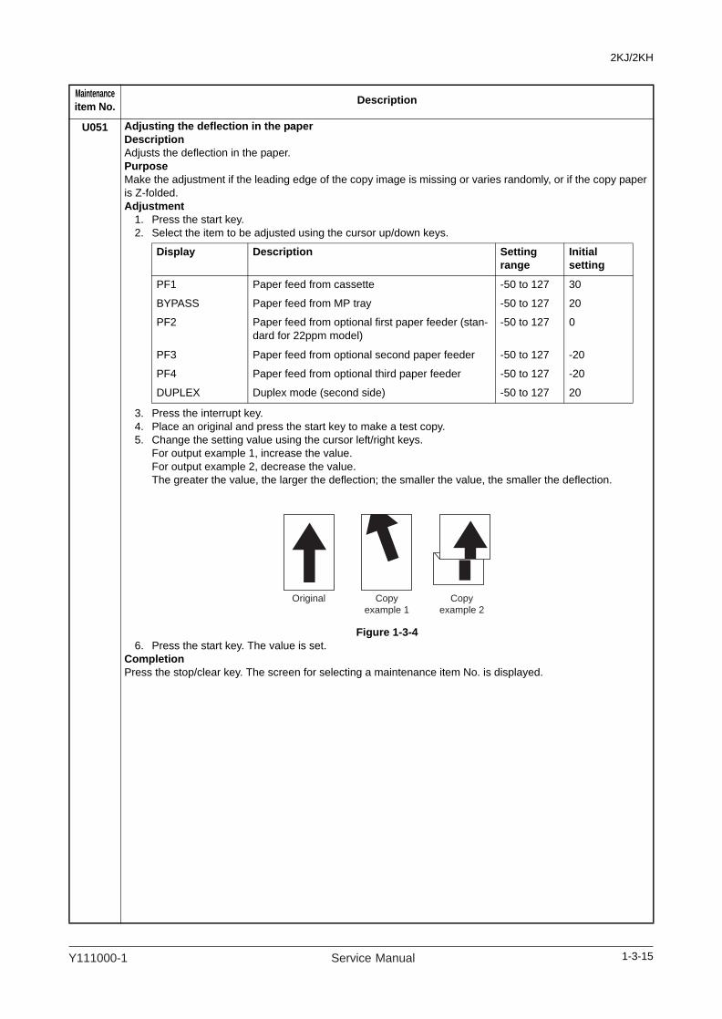
SERVICE MANUAL

PUBLICATION ISSUED BY:
Olivetti S.p.A.77, Via Jervis - 10015 Ivrea Italy
Copyright © 2009, OlivettiAll rights reserved
(TO)

This page is intentionally left blank.

Safety precautions
This booklet provides safety warnings and precautions for our service personnel to ensure the safety oftheir customers, their machines as well as themselves during maintenance activities. Service personnelare advised to read this booklet carefully to familiarize themselves with the warnings and precautionsdescribed here before engaging in maintenance activities.

Safety warnings and precautions
Various symbols are used to protect our service personnel and customers from physical danger and to prevent damage to their property. These symbols are described below:
DANGER: High risk of serious bodily injury or death may result from insufficient attention to or incorrectcompliance with warning messages using this symbol.
WARNING: Serious bodily injury or death may result from insufficient attention to or incorrect compliancewith warning messages using this symbol.
CAUTION: Bodily injury or damage to property may result from insufficient attention to or incorrectcompliance with warning messages using this symbol.
SymbolsThe triangle ( ) symbol indicates a warning including danger and caution. The specific pointof attention is shown inside the symbol.
General warning.
Warning of risk of electric shock.
Warning of high temperature.
indicates a prohibited action. The specific prohibition is shown inside the symbol.
General prohibited action.
Disassembly prohibited.
indicates that action is required. The specific action required is shown inside the symbol.
General action required.
Remove the power plug from the wall outlet.
Always ground the copier.

1.Installation Precautions
WARNING
• Do not use a power supply with a voltage other than that specified. Avoid multiple connections to one outlet: they may cause fire or electric shock. When using an extension cable, always check that it is adequate for the rated current. .............................................................................................
• Connect the ground wire to a suitable grounding point. Not grounding the copier may cause fire or electric shock. Connecting the earth wire to an object not approved for the purpose may cause explosion or electric shock. Never connect the ground cable to any of the following: gas pipes, lightning rods, ground cables for telephone lines and water pipes or faucets not approved by the proper authorities. ............................................................................................................................
CAUTION:
• Do not place the copier on an infirm or angled surface: the copier may tip over, causing injury. .......
• Do not install the copier in a humid or dusty place. This may cause fire or electric shock. ................• Do not install the copier near a radiator, heater, other heat source or near flammable material.
This may cause fire. .........................................................................................................................
• Allow sufficient space around the copier to allow the ventilation grills to keep the machine as cool as possible. Insufficient ventilation may cause heat buildup and poor copying performance. ...........
• Always handle the machine by the correct locations when moving it. ...............................................
• Always use anti-toppling and locking devices on copiers so equipped. Failure to do this may cause the copier to move unexpectedly or topple, leading to injury. ...........................................................
• Avoid inhaling toner or developer excessively. Protect the eyes. If toner or developer is acciden-tally ingested, drink a lot of water to dilute it in the stomach and obtain medical attention immedi-ately. If it gets into the eyes, rinse immediately with copious amounts of water and obtain medical attention. ......................................................................................................................................
• Advice customers that they must always follow the safety warnings and precautions in the copier’s instruction handbook. .....................................................................................................................

2.Precautions for Maintenance
WARNING
• Always remove the power plug from the wall outlet before starting machine disassembly. ...............
• Always follow the procedures for maintenance described in the service manual and other related brochures. .......................................................................................................................................
• Under no circumstances attempt to bypass or disable safety features including safety mechanisms and protective circuits. .....................................................................................................................
• Always use parts having the correct specifications. ..........................................................................• Always use the thermostat or thermal fuse specified in the service manual or other related bro-
chure when replacing them. Using a piece of wire, for example, could lead to fire or other serious accident. ..........................................................................................................................................
• When the service manual or other serious brochure specifies a distance or gap for installation of a part, always use the correct scale and measure carefully. ................................................................
• Always check that the copier is correctly connected to an outlet with a ground connection. .............• Check that the power cable covering is free of damage. Check that the power plug is dust-free. If it
is dirty, clean it to remove the risk of fire or electric shock. ..............................................................
• Never attempt to disassemble the optical unit in machines using lasers. Leaking laser light may damage eyesight. ...........................................................................................................................
• Handle the charger sections with care. They are charged to high potentials and may cause electric shock if handled improperly. ............................................................................................................
CAUTION• Wear safe clothing. If wearing loose clothing or accessories such as ties, make sure they are
safely secured so they will not be caught in rotating sections. ..........................................................
• Use utmost caution when working on a powered machine. Keep away from chains and belts. ........
• Handle the fixing section with care to avoid burns as it can be extremely hot. ..................................• Check that the fixing unit thermistor, heat and press rollers are clean. Dirt on them can cause
abnormally high temperatures. ........................................................................................................

• Do not remove the ozone filter, if any, from the copier except for routine replacement. ....................
• Do not pull on the AC power cord or connector wires on high-voltage components when removing them; always hold the plug itself. .....................................................................................................
• Do not route the power cable where it may be stood on or trapped. If necessary, protect it with a cable cover or other appropriate item. .............................................................................................
• Treat the ends of the wire carefully when installing a new charger wire to avoid electric leaks. ........
• Remove toner completely from electronic components. ...................................................................
• Run wire harnesses carefully so that wires will not be trapped or damaged. ....................................• After maintenance, always check that all the parts, screws, connectors and wires that were
removed, have been refitted correctly. Special attention should be paid to any forgotten connector, trapped wire and missing screws. ...................................................................................................
• Check that all the caution labels that should be present on the machine according to the instruction handbook are clean and not peeling. Replace with new ones if necessary. ......................................
• Handle greases and solvents with care by following the instructions below: .....................................· Use only a small amount of solvent at a time, being careful not to spill. Wipe spills off completely.· Ventilate the room well while using grease or solvents.· Allow applied solvents to evaporate completely before refitting the covers or turning the power
switch on.· Always wash hands afterwards.
• Never dispose of toner or toner bottles in fire. Toner may cause sparks when exposed directly to fire in a furnace, etc. .......................................................................................................................
• Should smoke be seen coming from the copier, remove the power plug from the wall outlet imme-diately. ............................................................................................................................................
3.Miscellaneous
WARNING
• Never attempt to heat the drum or expose it to any organic solvents such as alcohol, other than the specified refiner; it may generate toxic gas. .....................................................................................

This page is intentionally left blank.

2KJ/2KH
CONTENTS
1-1 Specifications1-1-1 Specifications..........................................................................................................................................1-1-11-1-2 Parts names............................................................................................................................................1-1-4
(1) Body ..................................................................................................................................................1-1-4(2) Operation panel.................................................................................................................................1-1-5
1-1-3 Machine cross section ............................................................................................................................1-1-6
1-2 Installation1-2-1 Installation environment .........................................................................................................................1-2-11-2-2 Unpacking and installation ......................................................................................................................1-2-2
(1) Installation procedure ........................................................................................................................1-2-2(2) Setting initial copy modes................................................................................................................1-2-11
1-2-3 Installing the key counter (option) .........................................................................................................1-2-121-2-4 Installing the cassette heater (option) ...................................................................................................1-2-171-2-5 Installing the cassette heater for paper feeder (option) (22 ppm model only).......................................1-2-19
1-3 Maintenance Mode1-3-1 Maintenance mode .................................................................................................................................1-3-1
(1) Executing a maintenance item ..........................................................................................................1-3-1(2) Maintenance modes item list.............................................................................................................1-3-2(3) Contents of the maintenance mode items.........................................................................................1-3-5
1-3-2 Management mode ...............................................................................................................................1-3-68(1) Using the management mode .........................................................................................................1-3-68(2) Setting the job accounting ...............................................................................................................1-3-69(3) Copy default ....................................................................................................................................1-3-70(4) Machine default ...............................................................................................................................1-3-71(5) MP Tray setting ...............................................................................................................................1-3-73(6) Checking the total counter and printing out the counter report .......................................................1-3-73(7) Report output...................................................................................................................................1-3-73(8) Language setting.............................................................................................................................1-3-73
1-4 Troubleshooting1-4-1 Paper misfeed detection .........................................................................................................................1-4-1
(1) Paper misfeed indication ...................................................................................................................1-4-1(2) Paper misfeed detection conditions ..................................................................................................1-4-2(3) Paper misfeeds .................................................................................................................................1-4-8
1-4-2 Self-diagnosis .......................................................................................................................................1-4-16(1) Self-diagnostic function ...................................................................................................................1-4-16(2) Self diagnostic codes ......................................................................................................................1-4-17
1-4-3 Image formation problems ....................................................................................................................1-4-25(1) No image appears (entirely white)...................................................................................................1-4-26(2) No image appears (entirely black)...................................................................................................1-4-26(3) Image is too light. ............................................................................................................................1-4-27(4) Background is visible.......................................................................................................................1-4-27(5) A white line appears longitudinally. .................................................................................................1-4-27(6) A black line appears longitudinally. .................................................................................................1-4-28(7) A black line appears laterally...........................................................................................................1-4-28(8) One side of the copy image is darker than the other.......................................................................1-4-28(9) Black dots appear on the image......................................................................................................1-4-28
(10) Image is blurred...............................................................................................................................1-4-29(11) The leading edge of the image is consistently misaligned with the original. ...................................1-4-29(12) The leading edge of the image is sporadically misaligned with the original. ...................................1-4-29(13) Paper creases. ................................................................................................................................1-4-29(14) Offset occurs. ..................................................................................................................................1-4-30(15) Image is partly missing....................................................................................................................1-4-30(16) Fusing is poor..................................................................................................................................1-4-30(17) Image is out of focus. ......................................................................................................................1-4-30(18) Image center does not align with the original center. ......................................................................1-4-31
1-4-4 Electric problems ..................................................................................................................................1-4-321-4-5 Mechanical problems ............................................................................................................................1-4-36

2KJ/2KH
1-5 Assembly and Disassembly1-5-1 Precautions for assembly and disassembly............................................................................................1-5-1
(1) Precautions .......................................................................................................................................1-5-1(2) Drum..................................................................................................................................................1-5-1(3) Toner .................................................................................................................................................1-5-1(4) How to tell a genuine Olivetti toner container....................................................................................1-5-2
1-5-2 Paper feed section ..................................................................................................................................1-5-3(1) Detaching and refitting the separation pulley ....................................................................................1-5-3(2) Detaching and refitting the forwarding pulley and paper feed pulley.................................................1-5-6(3) Detaching and refitting the feed roller (22 ppm model only)..............................................................1-5-9(4) Detaching and refitting the cassette separation pulley (22 ppm model only) ..................................1-5-11(5) Detaching and refitting the cassette forwarding pulley and cassette paper feed pulley
(22 ppm model only)........................................................................................................................1-5-13(6) Detaching and refitting the paper conveying unit ............................................................................1-5-16(7) Detaching and refitting the MP paper feed pulley and MP separation pad .....................................1-5-18(8) Detaching and refitting the left registration roller.............................................................................1-5-21(9) Detaching and refitting the right registration roller...........................................................................1-5-22
1-5-3 Optical section ......................................................................................................................................1-5-24(1) Detaching and refitting the exposure lamp......................................................................................1-5-24(2) Detaching and refitting the scanner wires .......................................................................................1-5-26
(2-1) Detaching the scanner wires ...................................................................................................1-5-26 (2-2) Fitting the scanner wires .........................................................................................................1-5-29
(3) Detaching and refitting the ISU (reference).....................................................................................1-5-33(4) Detaching and refitting the laser scanner unit .................................................................................1-5-35(5) Adjusting the longitudinal squareness (reference) ..........................................................................1-5-40
1-5-4 Drum section.........................................................................................................................................1-5-41(1) Detaching and refitting the drum unit ..............................................................................................1-5-41(2) Detaching and refitting the drum separation claws .........................................................................1-5-42(3) Detaching and refitting the main charger unit..................................................................................1-5-43
1-5-5 Developing section................................................................................................................................1-5-44(1) Detaching and refitting the developing unit .....................................................................................1-5-44
1-5-6 Transfer section ....................................................................................................................................1-5-45(1) Detaching and refitting the transfer roller ........................................................................................1-5-45
1-5-7 Fuser section ........................................................................................................................................1-5-47(1) Detaching and refitting the fuser unit...............................................................................................1-5-47(2) Detaching and refitting the press roller............................................................................................1-5-49(3) Detaching and refitting the fuser heater ..........................................................................................1-5-51(4) Detaching and refitting the heat roller separation claws..................................................................1-5-54(5) Detaching and refitting the heat roller .............................................................................................1-5-55(6) Detaching and refitting the fuser thermistor ....................................................................................1-5-57(7) Detaching and refitting the fuser thermostat ...................................................................................1-5-58(8) Adjusting front position of the fuser unit (adjusting lateral squareness) ..........................................1-5-59
1-5-8 Others ...................................................................................................................................................1-5-60(1) Detaching and refitting the eject unit ...............................................................................................1-5-60(2) Direction of installing the principal fan motors.................................................................................1-5-62
1-6 Requirements on PWB Replacement1-6-1 Upgrading the firmware...........................................................................................................................1-6-11-6-2 Adjustment-free variable resistors (VR) ..................................................................................................1-6-21-6-3 Remarks on main PWB and engine PWB replacement..........................................................................1-6-2
2-1 Mechanical construction2-1-1 Paper feed section ..................................................................................................................................2-1-12-1-2 Optical section ........................................................................................................................................2-1-3
(1) Image scanner section ......................................................................................................................2-1-3(2) Laser scanner section .......................................................................................................................2-1-5
2-1-3 Drum section...........................................................................................................................................2-1-72-1-4 Developing section..................................................................................................................................2-1-9
(1) Single component developing system.............................................................................................2-1-112-1-5 Transfer and separation sections..........................................................................................................2-1-122-1-6 Fuser section ........................................................................................................................................2-1-132-1-7 Eject and switchback sections ..............................................................................................................2-1-152-1-8 Duplex section ......................................................................................................................................2-1-17

2KJ/2KH
2-2 Electrical Parts Layout2-2-1 Electrical parts layout..............................................................................................................................2-2-1
(1) PWBs ................................................................................................................................................2-2-1(2) Switches and sensors .......................................................................................................................2-2-3(3) Motors ...............................................................................................................................................2-2-5(4) Others................................................................................................................................................2-2-6
2-3 Operation of the PWBs2-3-1 Power source PWB.................................................................................................................................2-3-12-3-2 Main PWB ...............................................................................................................................................2-3-32-3-3 Engine PWB............................................................................................................................................2-3-72-3-4 Cassette PWB.......................................................................................................................................2-3-132-3-5 Operation PWB.....................................................................................................................................2-3-162-3-6 Cassette main PWB (22 ppm model only) ............................................................................................2-3-18
2-4 AppendixesMaintenance parts list .............................................................................................................................2-4-1Periodic maintenance procedures ..........................................................................................................2-4-2Chart of image adjustment procedures...................................................................................................2-4-5Wiring diagram........................................................................................................................................2-4-7Paper feeder wiring diagram (22 ppm model only) .................................................................................2-4-8
INSTALLATION GUIDEDOCUMENT PROCESSORPAPER FEEDERDUPLEX UNITBUILT-IN FINISHERJOB SEPARATORFAX System (R)Scan System (F)B

2KJ/2KH
This page is intentionally left blank.

2KJ/2KH
Y110980-1 Y110980-1 Y110980-1 Y110980-1 Y110980-1
1-1 Specifications
1-1-1 Specifications
Type ................................................DesktopPrinting system ............................... Indirect electrostatic systemSupported original types .................Sheets, books and three-dimensional objects
Maximum original size: A3/LedgerOriginal feed system .......................FixedPaper weight...................................Cassette: 64 - 105 g/m2
MP tray: 45 - 160 g/m2
Paper type ......................................Cassette: Plain, Rough, Recycled, Preprinted, Bond, Color (Colour), Prepunched, Letterhead, High Quality, Custom 1 to 8
MP tray: Plain, Transparency (OHP film), Rough, Vellum, Labels, Recycled, Preprinted, Bond, Cardstock, Color (Colour), Prepunched, Letterhead, Thick, Envelope, High Quality, Custom 1 to 8
Paper size.......................................Cassette: A3, B4, A4, A4R, B5, B5R, A5R, Folio, Ledger, Legal, Letter, LetterR, StatementR, Oficio II, 8K, 16K
MP tray: A3, B4, A4, A4R, B5, B5R, A5R, B6R, A6R, Folio, Ledger, Legal, Letter, LetterR, Statement, Oficio II, 8K, 16KA3, B4, A4, A4R, B5, B5R, A5R, B6R, A6R, Folio, Ledger, Legal, Letter, LetterR, Hagaki, Oufuku Hagaki, Envelope DL, Envelope C5, Envelope C4, Envelope #10 (Comm. #10), Envelope #9 (Comm. #9), Envelope #6 (Comm. #6 3/4), Envelope Monarch, ISO B5, Youkei 2, Youkei 4, Executive, Statement, Oficio II, 8K, 16K, 16KR,
Zoom level ......................................Manual mode: 25 to 400%, 1% incrementsAuto mode: Preset zoom
Printing speed.................................18 ppm modelA4/Letter: 18 sheets/min.A4R/LetterR: 13 sheets/min.A3/Ledger: 8 sheets/min.B4/Legal: 8 sheets/min.B5: 16 sheets/min.B5R: 13 sheets/min.A5R: 10 sheets/min.
22 ppm modelA4/Letter: 22 sheets/min.A4R/LetterR: 13 sheets/min.A3/Ledger: 10 sheets/min.B4/Legal: 11 sheets/min.B5: 20 sheets/min.B5R: 13 sheets/min.A5R: 10 sheets/min.
First copy time ................................5.7 s or lessWarm-up time .................................Room temperature 22 °C/71.6 °F, 60% RH
Power on: 17.2 sLow power mode:10 sSleep mode: 17.2 s
Paper capacity ................................Cassette: 300 sheets (80 g/m2), 150 sheets (90 g/m2 or more)
MP tray: 100 sheets (A4/Letter or less), 25 sheets (B4/Legal or more)
Output tray capacity........................Top tray: 250 sheets (80 g/m2)When job separator installed: 150 sheets (80 g/m2)When built-in finisher installed: 100 sheets (80 g/m2)
Continuous copying ........................1 to 999 sheetsLight source .................................... Inert gas lampScanning system ............................Flat bed scanning by CCD image sensorPhotoconductor...............................OPC (drum diameter 30 mm)Image write system.........................Semiconductor laserCharging system.............................Single positive corona chargingDeveloping system .........................Single component developing system
Toner: magnetism tonerToner replenishing: Automatic from a toner container
Transfer system ..............................Transfer roller
1-1-1
Service Manual Service Manual Service Manual Service Manual Service Manual
Y111000-1 Service Manual

2KJ/2KH
Separation system ..........................Curvature separation and separation electrodeCleaning system .............................Blade and cleaning rollerCharge erasing system...................Exposure by cleaning lampFusing system.................................Heat roller
Heat source: Halogen heatersAbnormally high temperature protection devices: thermostats
Main memory ..................................Standard: 64 MBMaximum: 192 MB
Interface..........................................Memory card interface: 1USB interface connector: 1 (USB Hi-speed)Network interface: 1 (10 BASE-T/100 BASE-TX)Option interface: 1
Resolution.......................................600 x 600 dpiOperating environment ...................Temperature: 10 to 32.5°C/50 to 90.5°F
Humidity: 15 to 80% RHAltitude: 2500 m/8,202 ft maximumBrightness: 1500 lux maximum
Dimensions .....................................18 ppm model 568 (W) x 594 (D) x 502 (H) mm (main body only) 22 3/8" (W) x 23 3/8" (D) x 19 3/4" (H) (main body only)22 ppm model 568 (W) x 594 (D) x 607 (H) mm (main body only) 22 3/8" (W) x 23 3/8" (D) x 23 7/8" (H) (main body only)
Weight.............................................18 ppm model: 33 kg/72.8 lbs22 ppm model: 40 kg/88.2 lbs
Space required................................838 mm (W) x 594 (D) mm (using MP tray)33" (W) x 23 3/8" (D) (using MP tray)
Power source..................................120 V AC, 60 Hz, 9.7 A220 to 240 V AC, 50 Hz, 5.1 A
Options ...........................................Document processor, paper feeder, duplex unit, built-in finisher, job separator, key counter, FAX kit, network scanner kit, hard disk and expansion memory
Printer functionsPrinting speed.................................Same as copying speedFirst print time .................................5.7 s or lessResolution.......................................300 dpi, 600 dpi, Fast 1200Operating system............................Windows 2000 (Service Pack 2 or later), Windows XP, Windows Server 2003,
Windows Vista, Apple Macintosh OS 10.xInterface..........................................USB interface connector: 1 (USB Hi-speed)
Network interface: 1 (10 BASE-T/100 BASE-TX)Memory...........................................Standard: 128 MB
Maximum: 1152 MBPage description language .............PRESCRIBE
1-1-2
Service Manual Y110980-1
Service Manual Y111000-1

2KJ/2KH
Scanner functionsOperating system............................Windows 2000 (Service Pack 2 or later), Windows XP, Windows VistaSystem requirements......................CPU 600 MHz or higher
RAM 128 MB or moreResolution.......................................600 dpi, 400 dpi, 300 dpi, 200 dpiFile format.......................................TIFF (MMR compression), PDF (MMR compression)Scanning speed ..............................A4 landscape, Image quality: Text/Photo original
Single scanning: 22 images/min (600 dpi), 22 images/min (300 dpi)Dual scanning: 11 images/min (600 dpi), 11 images/min (300 dpi)
Network protocol.............................TCP/IPTransmission system ......................PC transmission: Scan to PC
E-mail transmission: Scan to E-mailTwain scan: TWAIN Driver
Duplex unitType ................................................ Internal typePaper weight...................................64 - 105 g/m2
Paper type ......................................Plain, RecycledPaper size.......................................A3, B4, A4, A4R, B5, B5R, A5R, Folio, Ledger, Legal, Letter, LetterR,
StatementR, Oficio II, 8K, 16KPower source..................................Electrically connected to the machine.Dimensions .....................................363 (W) x 54 (D) x 181 (H) mm
14 5/16" (W) x 2 1/8" (D) x 7 1/8" (H)Weight.............................................0.5 kg or less / 1.1 lbs or less
NOTE: These specifications are subject to change without notice.
1-1-3Y111000-1 Service Manual
2KJ/2KH
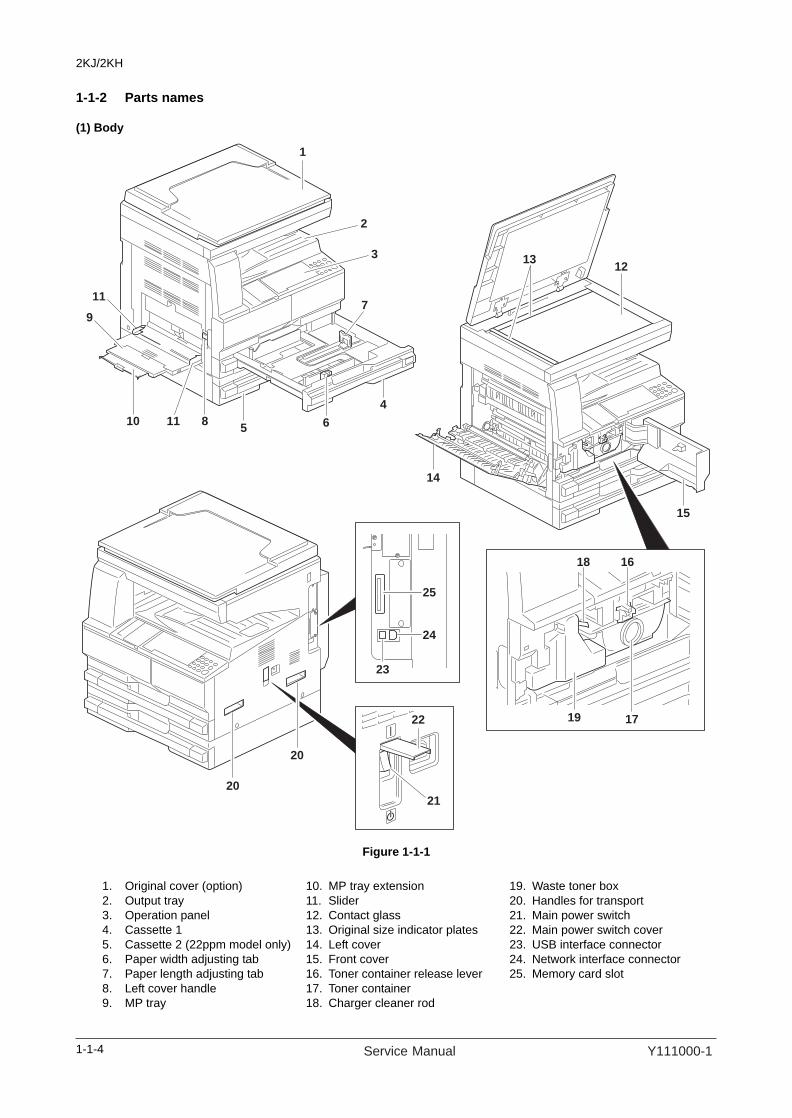
1-1-2 Parts names
(1) Body
Figure 1-1-1
1
1213
5
4
6
7
2
3
20
20
21
22
25
24
23
19
15
14
1618
17
11
9
1110 8
1. Original cover (option)2. Output tray3. Operation panel4. Cassette 15. Cassette 2 (22ppm model only)6. Paper width adjusting tab7. Paper length adjusting tab8. Left cover handle9. MP tray
10. MP tray extension11. Slider12. Contact glass13. Original size indicator plates14. Left cover15. Front cover16. Toner container release lever17. Toner container18. Charger cleaner rod
19. Waste toner box20. Handles for transport21. Main power switch22. Main power switch cover23. USB interface connector24. Network interface connector25. Memory card slot
1-1-4 Service Manual Y111000-1
2KJ/2KH
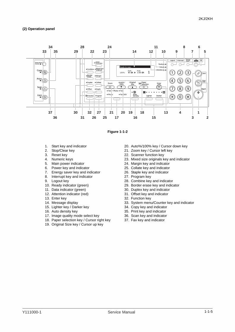
(2) Operation panel
Figure 1-1-2
33 14
118192021273230 4
1035 29 22 912 7 5
225263136
1337
3151617
23
34 28 24 811 6
1. Start key and indicator2. Stop/Clear key3. Reset key4. Numeric keys5. Main power indicator6. Power key and indicator7. Energy saver key and indicator8. Interrupt key and indicator9. Logout key10. Ready indicator (green)11. Data indicator (green)12. Attention indicator (red)13. Enter key14. Message display15. Lighter key / Darker key16. Auto density key17. Image quality mode select key18. Paper selection key / Cursor right key19. Original Size key / Cursor up key
20. Auto%/100% key / Cursor down key21. Zoom key / Cursor left key22. Scanner function key23. Mixed size originals key and indicator24. Margin key and indicator25. Collate key and indicator26. Staple key and indicator27. Program key28. Combine key and indicator29. Border erase key and indicator30. Duplex key and indicator31. Offset key and indicator32. Function key33. System menu/Counter key and indicator34. Copy key and indicator35. Print key and indicator36. Scan key and indicator37. Fax key and indicator
1-1-5Y111000-1 Service Manual

2KJ/2KH
1-1-3 Machine cross section
Figure 1-1-3 Machine cross section
2
2
1
7
6
3
4
8
5
Paper path
Light path
1. Paper feed section2. Optical section3. Drum section4. Developing section5. Transfer and separation sections6. Fuser section7. Eject and switchback sections8. Duplex section
1-1-6 Service Manual Y111000-1

2KJ/2KH
1-2 Installation
1-2-1 Installation environment
1. Temperature: 10 to 32.5°C/50 to 90.5°F2. Humidity: 15 to 80% RH3. Power supply: 120 V AC, 9.7 A
220 to 240 V AC, 5.1 A4. Power source frequency: 50 Hz ± 0.3%/60 Hz ± 0.3%5. Installation location
Avoid direct sunlight or bright lighting. Ensure that the photoconductor will not be exposed to direct sunlight or other strong light when removing paper jams.Avoid locations subject to high temperature and high humidity or low temperature and low humidity; an abrupt change in the environmental temperature; and cool or hot, direct air.Avoid places subject to dust and vibrations.Choose a surface capable of supporting the weight of the machine.Place the machine on a level surface (maximum allowance inclination: 1°).Avoid air-borne substances that may adversely affect the machine or degrade the photoconductor, such as mer-cury, acidic of alkaline vapors, inorganic gasses, NOx, SOx gases and chlorine-based organic solvents.Select a well-ventilated location.
6. Allow sufficient access for proper operation and maintenance of the machine.Machine front: 1000 mm/39 3/8" Machine rear: 100 mm/3 15/16"Machine right: 300 mm/11 13/16" Machine left: 300 mm/11 13/16
Figure 1-2-1 Installation dimensions
300 mm/11 13/16"300 mm/11 13/16"
1000 mm/39 3/8"
100 mm/3 15/16"
1-2-1Y111000-1 Service Manual

2KJ/2KH
1-2-2 Unpacking and installation
(1) Installation procedure
Unpack.
Remove the tapes.
Install the optional paper feeder.
Release the scanner pins.
Install the toner container.
Connect the power cord.
Load paper.
Installing toner.
Make test copies.
Attaching the operation label.
Attaching the cover label.
Output an own-status report(maintenance item U000).
Exit maintenance mode.
Start
Install other optional devices.
Install the waste toner box.
Install the optional original cover or the DP.
Completion of the machine installation.
1-2-2 Service Manual Y111000-1

2KJ/2KH
18 ppm model
Figure 1-2-2 Unpacking
Caution: Place the machine on a level surface.
Unpacking.
1. Machine2. Outer case3. Inner frame4. Skid5. Bottom left pad6. Bottom right pad7. Top left pad8. Top right pad9. Machine cover10. Eject spacer11. Document tray
12. Power cord13. Paper storage bags14. Plastic bag15. Plastic bag16. Cursor pins17. Cover label18. Cassette size label19. Operation label A20. Operation label B21. Hinge joints22. Barcode labels
1-2-3Y111000-1 Service Manual
2KJ/2KH
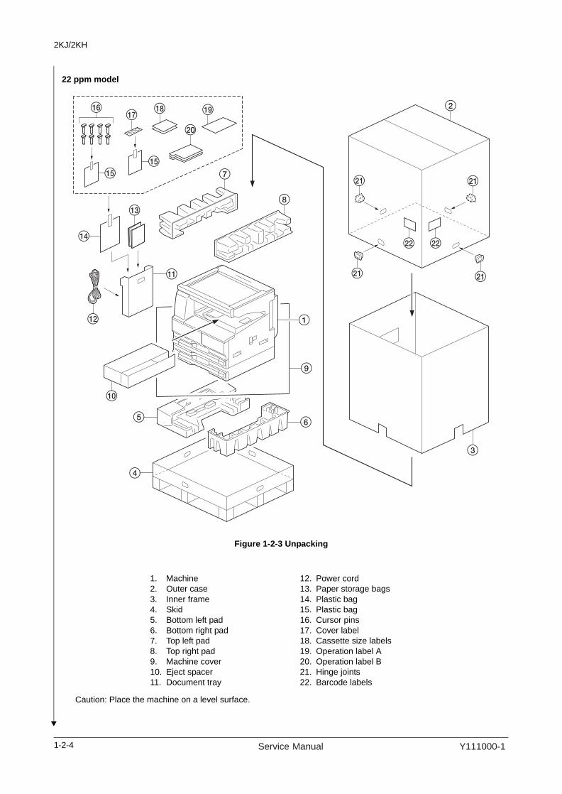
22 ppm model
Figure 1-2-3 Unpacking
Caution: Place the machine on a level surface.
1. Machine2. Outer case3. Inner frame4. Skid5. Bottom left pad6. Bottom right pad7. Top left pad8. Top right pad9. Machine cover10. Eject spacer11. Document tray
12. Power cord13. Paper storage bags14. Plastic bag15. Plastic bag16. Cursor pins17. Cover label18. Cassette size labels19. Operation label A20. Operation label B21. Hinge joints22. Barcode labels
1-2-4 Service Manual Y111000-1

2KJ/2KH
1. Remove four tapes and remove the plastic sheet.
Figure 1-2-4
2. Remove the tapes.18 ppm model: Five22 ppm model: Seven
Figure 1-2-5
Remove the tapes.
Tape
Tape
Tape
Plastic sheet
Tape
Tape*
*: 22 ppm model onlyTape*
Tape
Tape
Tape
Tape
Tape
1-2-5Y111000-1 Service Manual

2KJ/2KH
3. Pull the cassette out.4. Remove the tapes.
18 ppm model: One22 ppm model: Two (upper and lower cas-settes)
5. Push the cassette back in.
Figure 1-2-6
1. Install the optional paper feeder as neces-sary.
1. Remove two tapes.2. Remove two scanner pins.
Figure 1-2-7
1. Install the optional original cover or DP.
Tape
Cassette
Install the optional paper feeder.
Release the scanner pins.
Tape
Scanner pin
Scanner pin
Tape
Install the optional original cover or the DP.
1-2-6 Service Manual Y111000-1

2KJ/2KH
1. Install the optional devices (duplex unit, job separator, built-in finisher and/or fax kit etc.) as necessary.
1. Open the front cover.2. Hold the toner container vertically and tap
the upper part five times or more.Turn the toner container upside down and tap the upper part five times or more.
Figure 1-2-8
3. Shake the toner container up and down five times or more.Turn the toner container upside down and shake it five times or more.
Figure 1-2-9
4. Shake the toner container approximately five times in the horizontal direction to stir toner.
Figure 1-2-10
Install other optional devices.
Install the toner container.
Toner container
Tonercontainer
Tonercontainer
1-2-7Y111000-1 Service Manual

2KJ/2KH
5. Gently push the toner container into the machine.Push the container all the way into the machine until it locks in place.
Figure 1-2-11
1. Install the waste toner box in the machine.2. Close the front cover.
Figure 1-2-12
Toner container
Install the waste toner box.
Waste toner box
1-2-8 Service Manual Y111000-1
2KJ/2KH
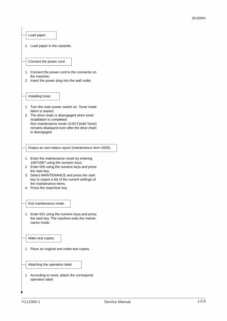
1. Load paper in the cassette.
1. Connect the power cord to the connector on the machine.
2. Insert the power plug into the wall outlet.
1. Turn the main power switch on. Toner instal-lation is started.
2. The drive chain is disengaged when toner installation is completed.Run maintenance mode U130 if [Add Toner] remains displayed even after the drive chain is disengaged.
1. Enter the maintenance mode by entering 10871087 using the numeric keys.
2. Enter 000 using the numeric keys and press the start key.
3. Select MAINTENANCE and press the start key to output a list of the current settings of the maintenance items.
4. Press the stop/clear key.
1. Enter 001 using the numeric keys and press the start key. The machine exits the mainte-nance mode.
1. Place an original and make test copies.
1. According to need, attach the correspond operation label.
Load paper.
Connect the power cord.
Installing toner.
Output an own-status report (maintenance item U000).
Exit maintenance mode.
Make test copies.
Attaching the operation label.
1-2-9Y111000-1 Service Manual

2KJ/2KH
1. Attach the cover labels to three screw holes in the machine.Right side: TwoLeft side: One
Figure 1-2-13
Attaching the cover label.
Right side
[22 ppm model]
[18 ppm model]
Left side
Cover label
Cover label
Cover label
Cover label
Cover label
Cover label
Completion of the machine installation.
1-2-10 Service Manual Y111000-1

2KJ/2KH
(2) Setting initial copy modes
Factory settings are as follows:
Maintenanceitem No. Contents Factory setting
U253 Switching between double and single counts DOUBLE COUNT(A3/LEDGER)
U254 Turning auto start function ON/OFF ON
U260 Selecting the timing for copy counting After ejection
U264 Setting the display order of the date MONTH-DATE-YEAR (inch specifications)DATE-MONTH-YEAR (metric specifications)
U277 Setting auto application change time 30 s
U326 Setting the black line cleaning indication ON
U342 Setting the ejection restriction ON
U343 Switching between duplex/simplex copy mode OFF
U344 Setting the low-power mode ENERGY STAR (inch specifications)GEEA (metric specifications)
1-2-11Y111000-1 Service Manual

2KJ/2KH
1-2-12
1-2-3 Installing the key counter (option)Installing the key counter requires the following component:Key counter (P/N AVGR03671G)Key counter set (P/N AVGR08516B)Key counter wire setKey counter mounting plate (P/N AVGR00804W)
Supplied parts of key counter set:Key counter socket assembly (P/N 127233J)Key counter cover Key counter mount Key counter retainerKey counter cover retainerTwo (2) EdgingsOne (1) Band One (1) M3 × 8 tap-tight P screw Two (2) M4 × 10 tap-tight P screws Two (2) M4 × 10 tap-tight S screws Two (2) M3 × 6 bronze flat-head screws One (1) M4 × 20 tap-tight S screwOne (1) M3 bronze nutOne (1) M3 × 8 bronze binding screwOne (1) M4 × 30 tap-tight S screwFive (5) M4 × 6 chrome TP screwsTwo (2) M4 × 10 chrome TP screws
Supplied parts of key counter wire set:Key counter wire (P/N AVGR11503G)Two (2) Wire saddlesOne (1) Edging
Procedure1. Press the power key on the operation panel
to off. Make sure that the Power lamp is off before turning off the main power switch. And then unplug the power cable from the wall outlet.
2. Fit the key counter socket assembly to the key counter retainer using two screws and nut.
3. Fit the key counter mount to the key counter cover using two screws.
4. Fit the key counter retainer to the key counter mount using two screws.
Figure 1-2-14
M3 x 6 flat-head screws
Key counter mount
Key counter cover
M4 x 6 screw
M4 x 6 screw
Key counter socket assembly(P/N 127233J)
M4 x 6 screw
M3 nut
Key counter retainerM4 x 6 screw
Service Manual Y111000-1

2KJ/2KH
5. Remove five screws and remove the rear cover.
Figure 1-2-15
6. Cut out the aperture on the right middle cover using nippers.
Figure 1-2-16
7. Remove two screws and remove the shield cover.
Figure 1-2-17
Screw
Screw
Screw
Screw
Screw
Rear cover
Aperture
Right middle cover
Shield cover
Screw
Screw
1-2-13Y111000-1 Service Manual

2KJ/2KH
8. Fit two wire saddles and the edging to machine.
Figure 1-2-18
9. Pass the key counter wire through two wire saddles and the edging.
Figure 1-2-19
Wire saddle
Wire saddle
Edging
Edging
Wire saddle
Wire saddle
Key counter wire
Edging
1-2-14 Service Manual Y111000-1

2KJ/2KH
10. Insert two bands of the key counter wire to the machine and shield cover.
11. Refit the shield cover.
Figure 1-2-20
12. Connect the 4-pin connector of the key counter wire to the YC12 on the engine PWB.Put the 1-pin connector that is not con-nected in the shield box.
13. Pull the other 4-pin connector out from the aperture of the right middle cover.
14. Refit the rear cover.
Figure 1-2-21
Bands
Key counter wire
Shield cover
YC12
Aperture
4-pinconnector
4-pinconnector
Key counter wire
Engine PWB
1-2-15Y111000-1 Service Manual

2KJ/2KH
1-2-16
15. Pass the 4-pin connector of the key counter signal cable through the aperture in the key counter mounting plate.
16. Hook the square hole on the key counter cover onto the key counter mounting plate.
Figure 1-2-22
17. Connect the 4-pin connector of the key counter signal cable to the 4-pin connector of the key counter wire.
18. Insert the hook of the key counter mounting plate in the aperture of the right middle cover.
19. Fit the key counter cover and the key counter mounting plate using the M4 x 30 screw.
20. Insert the key counter into the key counter socket assembly.
Figure 1-2-2321. Turn the main power switch on and enter the
maintenance mode.22. Run maintenance item U204 and select
"KEY-COUNTER".23. Exit the maintenance mode.24. Check that the message requesting the key
counter to be inserted is displayed on the message display when the key counter is pulled out.
25. Check that the counter counts up as copies are made.
Square hole
Key counter mounting plate
(AVGR00804W)
4-pinconnector
Aperture
key counter cover
key counter signal cable
Hook
Key counter cover
Key counter
mounting plate M4 x 30screw
4-pin connector
4-pin connector
Hook
Aperture
Service Manual Y111000-1

2KJ/2KH
1-2-17
1-2-4 Installing the cassette heater (option)Installing the cassette heater requires the following component:Cassette heater (P/N AVGR11493B): for 220 to 240 V specifications onlyOne (1) M3 x 8 S tight screw
Procedure1. Open the front cover.2. Remove the screw and release three hooks
and then remove the front right cover.3. Pull out the cassette.
Figure 1-2-24
Front right cover
Screw
Front right
coverHook
Hook
Hook
Y111000-1 Service Manual

2KJ/2KH
4. Pass the cassette heater cable through the edging and fit the cassette heater to the machine.
Figure 1-2-25
5. Attach the cassette heater using the M3 x 8 S tight screw.
6. Pass the cassette heater cable through the clamp. Connect the connector of the cas-sette heater cable to the connector of the machine.
7. Refit all the removed parts.
Figure 1-2-26
Cassette heater cable
Edging
Cassette heater
Cassette heater cable
M3 x 8 S tight screw
Connector
Clamp
1-2-18 Service Manual Y111000-1

2KJ/2KH
1-2-5 Installing the cassette heater for paper feeder (option) (22 ppm model only)Installing the cassette heater requires the following component:Cassette heater (P/N 303MH94060): for 220 to 240 V specifications onlyCassette heater (P/N 303MH94050): for 120 V specificationsOne (1) M3 x 8 P tight screw (P/N 7BB202308H)
Procedure1. Remove the screw and the pin and then
remove the cassette rear cover.2. Pull out the cassette.
Figure 1-2-27
3. Pass the cassette heater cable through the hole at the machine rear side.
4. Insert the stay of the cassette heater into the hole at the machine rear side.
5. Attach the cassette heater using the M3 x 8 P tight screw.
Figure 1-2-28
Pin
Screw
Cassette rear cover
Cassette heater
Cassette heater cable
Stay M3 x 8 P tight screw
1-2-19Y111000-1 Service Manual

2KJ/2KH
6. Connect the connector of the cassette heater cable to the connector of the machine.
7. Refit all the removed parts.
Figure 1-2-29
Cassette heater cable
Connector
1-2-20 Service Manual Y111000-1

2KJ/2KH
1-3 Maintenance Mode
1-3-1 Maintenance modeThe machine is equipped with a maintenance function which can be used to maintain and service the machine.
(1) Executing a maintenance item
Enter 10871087 using
the numeric keys.
Enter 001 using the cursor
up/down keys or numeric keys
and press the start key.
Enter the maintenance item
number using the cursor up/down keys
or numeric keys.
The selected maintenance item is run.
Press the stop/clear key.
Press the start key.
Start
End
Maintenance mode is entered.
The maintenance item is
selected.
Maintenance mode is exited.
Repeat the same
maintenance item?
Run another maintenance
item?
No
No
Yes
Yes
1-3-1Y111000-1 Service Manual

2KJ/2KH
(2) Maintenance modes item list
Section ItemNo.
Content of maintenance item Initialsetting*
General U000 Outputting an own-status report -
U001 Exiting the maintenance mode -
U002 Setting the factory default data -
U003 Setting the service telephone number ****************1,*2
U004 Displaying the machine number -
U005 Copying without paper -
U019 Displaying the ROM version -
Initialization U020 Initializing all data -
U021 Initializing counters and mode settings -
U022 Initializing backup memory -
U026 Evacuation of backup data -
U027 Return of backup data -
Drive, paper feed, paper conveying and cooling system
U030 Checking motor operation -
U031 Checking switches for paper conveying -
U032 Checking clutch operation -
U034 Adjusting the print start timingAdjusting the leading edge registrationAdjusting the center lineAdjusting the trailing edge registration
2.8/0.0/0.0/0.0/0.0/0.8*1
-2.4/0.0/0.0/0.0/0.0/0.0*1
2.0*1
U035 Setting the printing area for folio paperLength/Width 330/210*1
U051 Adjusting the deflection in the paper 30/20/0/-20/-20/20*1
U053 Setting the adjustment of the motor speed 0.3/0.7/-0.5/0.0/-0.1-0.1/-0.3/0.0/0.0/0.5/0.0*1
Optical U060 Adjusting the scanner input properties 12*1
U061 Turning the exposure lamp on -
U063 Adjusting the shading position 0*1
U065 Adjusting the scanner magnificationMain scanning direction/auxiliary scanning direction 0/-10*1
U066 Adjusting the scanner leading edge registration 0/0*1
U067 Adjusting the scanner center line -4/0*1
U068 Adjusting the scanning position for originals from the DP 0*1
U070 Adjusting the DP magnification 0/0*1
U071 Adjusting the DP scanning timing 0/0/0/0*1
U072 Adjusting the DP center line 0/0/0*1
U073 Checking scanner operation -
U074 Adjusting the DP input light luminosity 0*1
U076 Executing DP automatic adjustment -
U087 Setting DP reading position modification operation ON/35*1
U089 Outputting a MIP-PG pattern -
U092 Adjusting the scanner automatically -
U093 Setting the exposure density gradientText and photo/Text/Photo 0/0/0/2/3*1
U099 Adjusting original size detection 170/30/240*1
*Initial setting for executing U020, *1: The item initialized for executing U020, *2: The item initialized for executing U021
1-3-2 Service Manual Y111000-1

2KJ/2KH
High voltage U100 Setting the main high voltageGrid control voltageCopy intervalCopy quantityCorrection amount
107*1
60*1
50*1
10*1
U101 Setting the other high voltagesSetting the developing biasSetting the transfer voltageSetting the separation voltage
27/45/22/45*1
123/126/33/31*1
1/20/42/2*1
U110 Checking the drum count -
Developing U130 Initial setting for the developing unit -
U144 Setting toner loading operation OFF/5/30*1
U150 Checking sensors for toner -
U157 Checking/clearing the developing drive time -
U158 Checking the developing count -
Fuser and cleaning
U161 Setting the fuser control temperaturePrimary stabilization fixing temperatureSecondary stabilization fixing temperatureCopying operation temperature 1Copying operation temperature 2
145*1
165*1
175*1
185*1
1*1
2*1
U162 Stabilizing fixing forcibly -
U163 Resetting the fuser problem data -
U167 Checking/clearing the fuser counts -
U198 Setting the fuser phase control OFF*1,*2
U199 Checking the fuser temperature -
Operationpanel andsupportequipment
U200 Turning all LEDs on -
U202 Setting the KMAS host monitoring system -
U203 Checking DP operation -
U204 Setting the presence or absence of a key card or key counter OFF*1,*2
U207 Checking the operation panel keys -
U233 Limiting job separator output MODE0*1
U243 Checking the operation of the DP motors -
U244 Checking the DP switches -
U245 Checking messages -
U246 Setting the finisher 4/4/4*1
U249 Checking the paper ejection to optional devices -
Mode setting U250 Setting the maintenance cycle 150000*1,*2
U251 Checking/clearing the maintenance count -
U252 Setting the destination JAPAN*1
U253 Switching between double and single counts DOUBLE COUNT(A3/LEDGER)*1,*2
U254 Turning auto start function ON/OFF ON*1,*2
U260 Selecting the timing for copy counting EJECT*1,*2
Section ItemNo.
Content of maintenance item Initialsetting*
*Initial setting for executing U020, *1: The item initialized for executing U020, *2: The item initialized for executing U021
1-3-3Y111000-1 Service Manual
2KJ/2KH
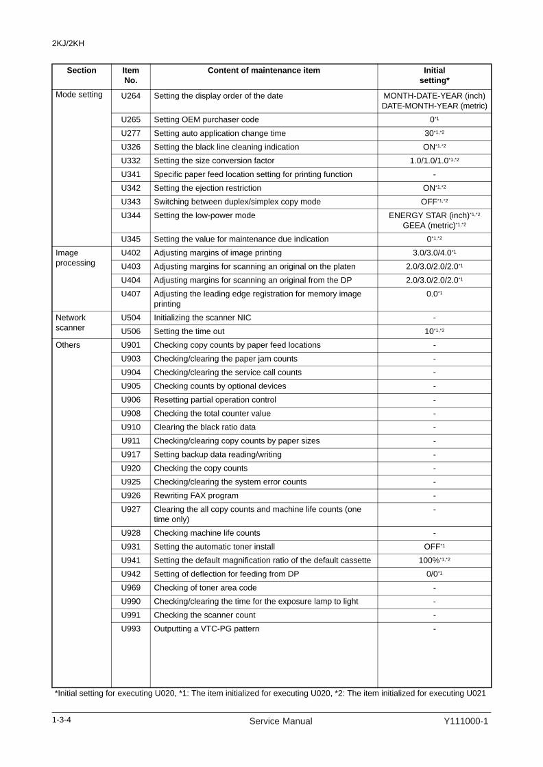
Mode setting U264 Setting the display order of the date MONTH-DATE-YEAR (inch)DATE-MONTH-YEAR (metric)
U265 Setting OEM purchaser code 0*1
U277 Setting auto application change time 30*1,*2
U326 Setting the black line cleaning indication ON*1,*2
U332 Setting the size conversion factor 1.0/1.0/1.0*1,*2
U341 Specific paper feed location setting for printing function -
U342 Setting the ejection restriction ON*1,*2
U343 Switching between duplex/simplex copy mode OFF*1,*2
U344 Setting the low-power mode ENERGY STAR (inch)*1,*2
GEEA (metric)*1,*2
U345 Setting the value for maintenance due indication 0*1,*2
Imageprocessing
U402 Adjusting margins of image printing 3.0/3.0/4.0*1
U403 Adjusting margins for scanning an original on the platen 2.0/3.0/2.0/2.0*1
U404 Adjusting margins for scanning an original from the DP 2.0/3.0/2.0/2.0*1
U407 Adjusting the leading edge registration for memory image printing
0.0*1
Networkscanner
U504 Initializing the scanner NIC -
U506 Setting the time out 10*1,*2
Others U901 Checking copy counts by paper feed locations -
U903 Checking/clearing the paper jam counts -
U904 Checking/clearing the service call counts -
U905 Checking counts by optional devices -
U906 Resetting partial operation control -
U908 Checking the total counter value -
U910 Clearing the black ratio data -
U911 Checking/clearing copy counts by paper sizes -
U917 Setting backup data reading/writing -
U920 Checking the copy counts -
U925 Checking/clearing the system error counts -
U926 Rewriting FAX program -
U927 Clearing the all copy counts and machine life counts (one time only)
-
U928 Checking machine life counts -
U931 Setting the automatic toner install OFF*1
U941 Setting the default magnification ratio of the default cassette 100%*1,*2
U942 Setting of deflection for feeding from DP 0/0*1
U969 Checking of toner area code -
U990 Checking/clearing the time for the exposure lamp to light -
U991 Checking the scanner count -
U993 Outputting a VTC-PG pattern -
Section ItemNo.
Content of maintenance item Initialsetting*
*Initial setting for executing U020, *1: The item initialized for executing U020, *2: The item initialized for executing U021
1-3-4 Service Manual Y111000-1

2KJ/2KH
(3) Contents of the maintenance mode items
Maintenanceitem No. Description
U000 Outputting an own-status reportDescriptionPrints out a list of the current settings of all maintenance items, and occurrences of paper jams and service calls.PurposeTo check the current setting of the maintenance items, or the occurrences of paper jams and service calls.Before initializing or replacing the backup RAM, print out a list of the current settings of the maintenance items so that you can reenter the same settings after initialization or replacement.Method
1. Press the start key.2. Select the item to be output.
3. Press the start key. The interrupt copy mode is entered and a list is output.When A4/Letter paper is available, a report of this size is output. If not, specify the paper feed location.When output is complete, the screen for selecting an item is displayed.
CompletionPress the stop/clear key. The screen for selecting a maintenance item No. is displayed.
U001 Exiting the maintenance modeDescriptionExits the maintenance mode and returns to the normal copy mode.PurposeTo exit the maintenance mode.MethodPress the start key. The normal copy mode is entered.
U002 Setting the factory default dataDescriptionRestores the machine conditions to the factory default settings.PurposeTo move the mirror frame of the scanner to the position for transport (position in which the frame can be fixed).Method
1. Press the start key.2. Select the [EXECUTE] using the cursor up/down keys.3. Press the start key.
The mirror frame of the scanner returns to the position for transport.4. Turn the main power switch off and on.
Display Output listMAINTENANCE List of the current settings of the maintenance modes
JAM List of the paper jam occurrences
SERVICE CALL List of the service call occurrences
1-3-5Y111000-1 Service Manual

2KJ/2KH
U003 Setting the service telephone numberDescriptionSets the telephone number to be displayed when a service call code is detected.PurposeTo set the telephone number to call service when installing the machine.Setting
1. Press the start key.2. Enter a telephone number (up to 15 digits) using the numeric keys.
Move the cursor using the cursor left/right keys and select a number or symbol using the cursor up/down keys.To enter symbols, press the keys shown below as required.
3. Press the start key. The phone number is set. CompletionPress the stop/clear key. The screen for selecting a maintenance item No. is displayed.
U004 Displaying the machine numberDescriptionDisplays the machine number.PurposeTo check the machine number.Method
1. Press the start key. The currently machine number is displayed.CompletionPress the stop/clear key. The screen for selecting a maintenance item No. is displayed.
Maintenanceitem No. Description
Key Symbol* key *
# key #
Image mode selection key (
Auto density key )
Lighter key -
Darker key Space
1-3-6 Service Manual Y111000-1

2KJ/2KH
U005 Copying without paperDescriptionSimulates the copy operation without paper feed.PurposeTo check the overall operation of the machine.Method
1. Press the start key.2. Select the item to be operated.
3. Press the start key.4. Press the interrupt key. The copy mode screen is displayed.5. Set the operation conditions required on the copy mode screen. Changes in the following settings can
be made.Paper feed locationsMagnificationsSimplex or duplex copy modeNumber of copies: in simplex copy mode, continuous copying is performed when set to 999; in duplex copy mode, continuous copying is performed regardless of the setting.Copy densityKeys on the operation panel
6. To control the paper feed pulley, remove all the paper in the drawers, or the drawers. With the paper present, the paper feed pulley does not operate.
7. Press the start key. The operation starts.Copy operation is simulated without paper under the set conditions.To stop continuous operation, press the stop/clear key.
8. To return to the screen for selecting an item, press the interrupt key.CompletionPress the stop/clear key. The screen for selecting a maintenance item No. is displayed.
Maintenanceitem No. Description
Display OperationPPC Only the machine operates.
PPC + DP Both the machine and DP operate (continuous operation).
1-3-7Y111000-1 Service Manual

2KJ/2KH
U019 Displaying the ROM versionDescriptionDisplays the part number of the ROM fitted to each PWB.PurposeTo check the part number or to decide, if the newest version of ROM is installed.Method
1. Press the start key. The ROM version are displayed.2. Change the screen using the cursor up/down keys.
Completion Press the stop/clear key. The screen for selecting a maintenance item No. is displayed.
U020 Initializing all dataDescriptionInitializes all the backup RAM on the main PWB to return to the original settings.Refer to *1 of the maintenance mode item list about the item initialized.Reset each intialized mode based on an own-status report U000 printed at installing the machine.PurposeTo be executed as required.Method
1. Press the start key.2. Select the [EXECUTE] using the cursor up/down keys.3. Press the start key. All data in the backup memory is initialized and the default setting for the Japan
specifications is registered.4. When initialization is complete, the machine automatically returns to the same status as when the main
power switch is turned on.
Maintenanceitem No. Description
Display DescriptionMAIN Main ROM
ENGINE Engine ROM
LANG(St) Standard language ROM
LANG(Op) Optional language ROM
MAIN BOOT Boot of main ROM
PRINTER Printer ROM
NWS Optional network scanner ROM
DP Optional DP ROM
FINISHER Optional built-in finisher ROM
CASS2 Optional first paper feeder ROM (standard for 22 ppm model)
CASS3 Optional second paper feeder ROM
CASS4 Optional third paper feeder ROM
1-3-8 Service Manual Y111000-1

2KJ/2KH
U021 Initializing counters and mode settingsDescriptionInitializes all settings, except those pertinent to the type of machine, namely each counter, service call history and mode setting. Also initializes backup RAM according to region specification selected in maintenance item U252 Setting the destination.Refer to *2 of the maintenance mode item list about the item initialized.PurposeTo return the machine settings to their factory default.Method
1. Press the start key.2. Select the [EXECUTE] using the cursor up/down keys.3. Press the start key. All data other than that for adjustments due to variations between machines is initial-
ized based on the destination setting.4. When initialization is complete, the machine automatically returns to the same status as when the main
power switch is turned on.
U022 Initializing backup memory DescriptionInitializes only the data set for the optical section or initializes various setting data when installing the optionalnetwork scanner board. PurposeTo be executed as required.Method
1. Press the start key.2. Select the [EXECUTE] using the cursor up/down keys.3. Press the start key.
The data for the optical section (U060 to 067, U092 to 099, U403, U990 and U991) is initialized.The setting data of scanner function initial settings are initialized, and the registered transmission and reception are cleared.
Completion Press the stop/clear key. The screen for selecting a maintenance item No. is displayed.
U026 Evacuation of backup data DescriptionTransfers the backup data of the main PWB to the EEPROM. PurposeUsed when replacing the main PWB. Method
1. Press the start key.2. Select the [EXECUTE] using the cursor up/down keys.3. Press the start key to transfer the backup data. The screen displays the result.
EXECUTE CHECK SUM : **** CODE : XXXX (See the table below)
4. Press the stop/clear key.Completion Press the stop/clear key. The screen for selecting a maintenance item No. is displayed.
Maintenanceitem No. Description
Code Description
0000 Processing ends correctly.
0101 Verification abnormality occurs.
0102 Verification abnormality occurs at the time of check sum entry.
1-3-9Y111000-1 Service Manual
2KJ/2KH
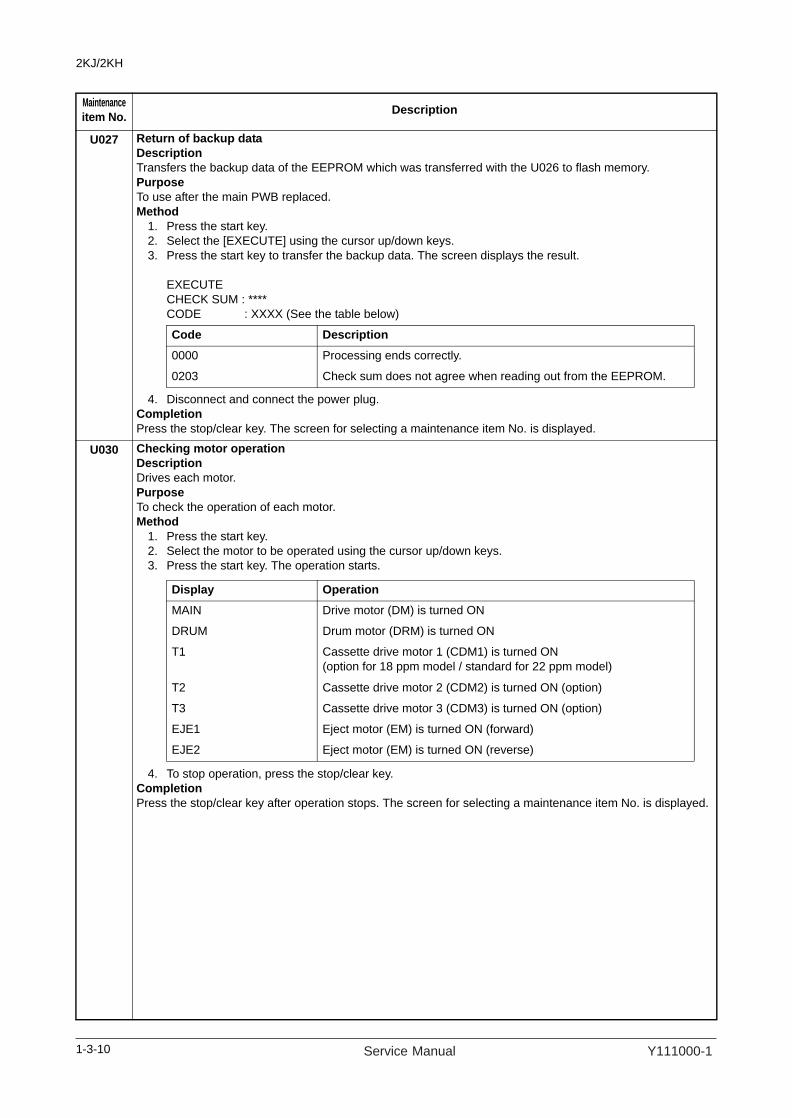
U027 Return of backup dataDescriptionTransfers the backup data of the EEPROM which was transferred with the U026 to flash memory.PurposeTo use after the main PWB replaced.Method
1. Press the start key.2. Select the [EXECUTE] using the cursor up/down keys.3. Press the start key to transfer the backup data. The screen displays the result.
EXECUTE CHECK SUM : **** CODE : XXXX (See the table below)
4. Disconnect and connect the power plug.Completion Press the stop/clear key. The screen for selecting a maintenance item No. is displayed.
U030 Checking motor operationDescriptionDrives each motor.PurposeTo check the operation of each motor.Method
1. Press the start key.2. Select the motor to be operated using the cursor up/down keys. 3. Press the start key. The operation starts.
4. To stop operation, press the stop/clear key.Completion Press the stop/clear key after operation stops. The screen for selecting a maintenance item No. is displayed.
Maintenanceitem No. Description
Code Description
0000 Processing ends correctly.
0203 Check sum does not agree when reading out from the EEPROM.
Display OperationMAIN Drive motor (DM) is turned ON
DRUM Drum motor (DRM) is turned ON
T1 Cassette drive motor 1 (CDM1) is turned ON(option for 18 ppm model / standard for 22 ppm model)
T2 Cassette drive motor 2 (CDM2) is turned ON (option)
T3 Cassette drive motor 3 (CDM3) is turned ON (option)
EJE1 Eject motor (EM) is turned ON (forward)
EJE2 Eject motor (EM) is turned ON (reverse)
1-3-10 Service Manual Y111000-1

2KJ/2KH
U031 Checking switches for paper conveyingDescriptionDisplays the on-off status of each paper detection switch on the paper path.PurposeTo check if the switches for paper conveying operate correctly.Method
1. Press the start key.2. Turn each switch on and off manually to check the status.
When a switch is detected to be in the ON position, the display for that switch will be highlighted.
Completion Press the stop/clear key. The screen for selecting a maintenance item No. is displayed.
U032 Checking clutch operationDescriptionTurns each clutch or solenoid on.PurposeTo check the operation of each clutch or solenoid.Method
1. Press the start key.2. Select the clutch or solenoid to be operated using the cursor up/down keys.3. Press the start key. The clutch or solenoid turns on for 1 s.
Completion Press the stop/clear key. The screen for selecting a maintenance item No. is displayed.
Maintenanceitem No. Description
Display Switches
EJE Eject switch (ESW)
RES Registration switch (RSW)
PF2 Cassette feed switch 1 (CFSW1)(option for 18 ppm model / standard for 22 ppm model)
PF3 Cassette feed switch 2 (CFSW2) (option)
BRA Feedshift switch (FSSW)
DUP Duplex paper conveying switch (DUPPCSW) (option)
JOB Job eject switch (JBESW) (option)
Display Clutches and solenoid
PF1 Paper feed clutch (PFCL)
PFBYP MP solenoid (MPSOL)
REG Registration clutch (RCL)
DUP Duplex feed clutch (DUPFCL)
PF2 Cassette paper feed clutch 1 (CPFCL1)(option for 18 ppm model / standard for 22 ppm model)
PF3 Cassette paper feed clutch 2 (CPFCL2) (option)
PF4 Cassette paper feed clutch 3 (CPFCL3) (option)
1-3-11Y111000-1 Service Manual

2KJ/2KH
U034 Adjusting the print start timingDescriptionAdjusts the leading edge registration or center line.PurposeMake the adjustment if there is a regular error between the leading edges of the copy image and original.Make the adjustment if there is a regular error between the center lines of the copy image and original.Make the adjustment if there is a regular error between the trailing edges of the copy image and original.Method
1. Press the start key.2. Select the item to be adjusted using the cursor up/down keys. The setting screen for the selected item is
displayed.
Adjustment: Leading edge registration adjustment1. Select the item to be adjusted using the cursor up/down keys.
2. Press the interrupt key.3. Press the start key to output a test pattern.4. Change the setting value using the cursor left/right keys.
For output example 1, decrease the value. For output example 2, increase the value.
Figure 1-3-15. Press the start key. The value is set.
CautionCheck the copy image after the adjustment. If the image is still incorrect, perform the following adjustments in maintenance mode.
Maintenanceitem No. Description
Display DescriptionADJ. RCL ON TIMING Leading edge registration adjustment
ADJ. LSU ON TIMING Center line adjustment
ADJ. MGN REAR Trailing edge margin adjustment
Display Description Settingrange
Initialsetting
Change invalue per step
RCL ON Paper feed from cassette -5.0 to 10.0 2.8 0.1 mm
RCL BYP Paper feed from MP tray -5.0 to 10.0 0.0 0.1 mm
RCL T1 Paper feed from optional first paper feeder (standard for 22ppm model)
-5.0 to 10.0 0.0 0.1 mm
RCL T2 Paper feed from optional second paper feeder
-5.0 to 10.0 0.0 0.1 mm
RCL T3 Paper feed from optional third paper feeder
-5.0 to 10.0 0.0 0.1 mm
RCL DUP Duplex mode (second side) -5.0 to 10.0 0.8 0.1 mm
Correct image Output
example 1
Output
example 2
Leading edge registration (20 ± 1.0 mm)
U034 U066(P.1-3-19)
U071(P.1-3-23)
1-3-12 Service Manual Y111000-1

2KJ/2KH
U034 Adjustment: Center line adjustment1. Select the item to be adjusted using the cursor up/down keys.
2. Press the interrupt key.3. Press the start key to output a test pattern.4. Change the setting value using the cursor left/right keys.
For output example 1, decrease the value.For output example 2, increase the value.
Figure 1-3-25. Press the start key. The value is set.
CautionCheck the copy image after the adjustment. If the image is still incorrect, perform the following adjustments in maintenance mode.
Maintenanceitem No. Description
Display Description Settingrange
Initialsetting
Change invalue per step
LSU OUT Paper feed from cassette -7.0 to 10.0 -2.4 0.1 mm
LSU BYP Paper feed from MP tray -7.0 to 10.0 0.0 0.1 mm
LSU T1 Paper feed from optional first paper feeder (standard for 22ppm model)
-7.0 to 10.0 0.0 0.1 mm
LSU T2 Paper feed from optional second paper feeder
-7.0 to 10.0 0.0 0.1 mm
LSU T3 Paper feed from optional third paper feeder
-7.0 to 10.0 0.0 0.1 mm
LSU DUP Duplex mode (second side) -7.0 to 10.0 0.0 0.1 mm
Center line of printing (± 1.0 mm)
Correct image Output
example 1
Output
example 2
U034 U067(P.1-3-20)
U072(P.1-3-25)
1-3-13Y111000-1 Service Manual

2KJ/2KH
U034 Adjustment: Trailing edge margin adjustment1. Select [MGN REAR].
2. Press the interrupt key.3. Press the start key to output a test pattern.4. Change the setting value using the cursor left/right keys.
For output example, increase the value.
Figure 1-3-35. Press the start key. The value is set.
CompletionPress the stop/clear key. The screen for selecting a maintenance item No. is displayed.
U035 Setting the printing area for folio paperDescriptionChanges the printing area for copying on folio paper.PurposeTo prevent cropped images on the trailing edge or left/right side of copy paper by setting the actual printing area for folio paper.Setting
1. Press the start key.2. Select the item to be set using the cursor up/down keys.3. Change the setting using the cursor left/right keys.
4. Press the start key. The value is set. CompletionPress the stop/clear key. The screen for selecting a maintenance item No. is displayed.
Maintenanceitem No. Description
Display Description Settingrange
Initialsetting
Change invalue per step
MGN REAR Trailing edge margin adjustment -4.0 to 10.0 2.0 0.1 ms
Correct imageOutput
example
Trailing edge margin
Display Setting Setting range Initial setting
LENGTH DATA Length 330 to 356 mm 330
WIDTH DATA Width 200 to 220 mm 210
1-3-14 Service Manual Y111000-1
2KJ/2KH
U051 Adjusting the deflection in the paperDescriptionAdjusts the deflection in the paper.PurposeMake the adjustment if the leading edge of the copy image is missing or varies randomly, or if the copy paper is Z-folded.Adjustment
1. Press the start key.2. Select the item to be adjusted using the cursor up/down keys.
3. Press the interrupt key.4. Place an original and press the start key to make a test copy.5. Change the setting value using the cursor left/right keys.
For output example 1, increase the value.For output example 2, decrease the value.The greater the value, the larger the deflection; the smaller the value, the smaller the deflection.
Figure 1-3-46. Press the start key. The value is set.
CompletionPress the stop/clear key. The screen for selecting a maintenance item No. is displayed.
Maintenanceitem No. Description
Display Description Settingrange
Initialsetting
PF1 Paper feed from cassette -50 to 127 30
BYPASS Paper feed from MP tray -50 to 127 20
PF2 Paper feed from optional first paper feeder (stan-dard for 22ppm model)
-50 to 127 0
PF3 Paper feed from optional second paper feeder -50 to 127 -20
PF4 Paper feed from optional third paper feeder -50 to 127 -20
DUPLEX Duplex mode (second side) -50 to 127 20
Original Copy
example 1
Copy
example 2
1-3-15Y111000-1 Service Manual
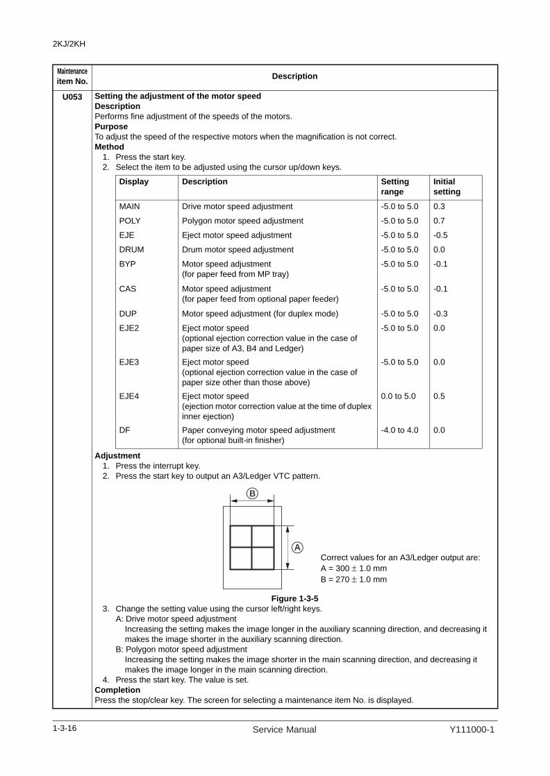
2KJ/2KH
U053 Setting the adjustment of the motor speedDescriptionPerforms fine adjustment of the speeds of the motors.PurposeTo adjust the speed of the respective motors when the magnification is not correct.Method
1. Press the start key.2. Select the item to be adjusted using the cursor up/down keys.
Adjustment1. Press the interrupt key.2. Press the start key to output an A3/Ledger VTC pattern.
Figure 1-3-53. Change the setting value using the cursor left/right keys.
A: Drive motor speed adjustmentIncreasing the setting makes the image longer in the auxiliary scanning direction, and decreasing it makes the image shorter in the auxiliary scanning direction.
B: Polygon motor speed adjustmentIncreasing the setting makes the image shorter in the main scanning direction, and decreasing it makes the image longer in the main scanning direction.
4. Press the start key. The value is set.CompletionPress the stop/clear key. The screen for selecting a maintenance item No. is displayed.
Maintenanceitem No. Description
Display Description Settingrange
Initialsetting
MAIN Drive motor speed adjustment -5.0 to 5.0 0.3
POLY Polygon motor speed adjustment -5.0 to 5.0 0.7
EJE Eject motor speed adjustment -5.0 to 5.0 -0.5
DRUM Drum motor speed adjustment -5.0 to 5.0 0.0
BYP Motor speed adjustment (for paper feed from MP tray)
-5.0 to 5.0 -0.1
CAS Motor speed adjustment (for paper feed from optional paper feeder)
-5.0 to 5.0 -0.1
DUP Motor speed adjustment (for duplex mode) -5.0 to 5.0 -0.3
EJE2 Eject motor speed(optional ejection correction value in the case of paper size of A3, B4 and Ledger)
-5.0 to 5.0 0.0
EJE3 Eject motor speed(optional ejection correction value in the case of paper size other than those above)
-5.0 to 5.0 0.0
EJE4 Eject motor speed(ejection motor correction value at the time of duplex inner ejection)
0.0 to 5.0 0.5
DF Paper conveying motor speed adjustment(for optional built-in finisher)
-4.0 to 4.0 0.0
Correct values for an A3/Ledger output are:A = 300 ± 1.0 mmB = 270 ± 1.0 mm
1-3-16 Service Manual Y111000-1

2KJ/2KH
U060 Adjusting the scanner input propertiesDescriptionAdjusts the image scanning density.PurposeUsed when the entire image appears too dark or light.Setting
1. Press the start key.2. Change the setting using the cursor left/right keys.
Increasing the setting makes the density lower, and decreasing it makes the density higher.3. Press the start key. The value is set.
SupplementWhile this maintenance item is being executed, copying from an original is available in interrupt copying mode(which is activated by pressing the interrupt key).
CompletionPress the stop/clear key. The screen for selecting a maintenance item No. is displayed.
CautionThe following settings are also reset to the initial values by performing this maintenance item: Exposure density gradient set in maintenance mode (U093) Exposure set in the copy default item of the copier management mode
U061 Turning the exposure lamp onDescriptionTurns the exposure lamp on.PurposeTo check the exposure lamp.Method
1. Press the start key.2. Press the start key. The exposure lamp lights.3. To turn the exposure lamp off, press the stop/clear key.
CompletionPress the stop/clear key. The screen for selecting a maintenance item No. is displayed.
U063 Adjusting the shading positionDescriptionChanges the shading position of the scanner.PurposeUsed when white lines continue to appear longitudinally on the image after the shading plate is cleaned. This is due to flaws or stains inside the shading plate. To prevent this problem, the shading position should be changed so that shading is possible without being affected by the flaws or stains.Setting
1. Press the start key.2. Change the setting using the cursor left/right keys.
Increasing the setting moves the shading position toward the machine left, and decreasing it moves the position toward the machine right.
3. Press the start key. The value is set.
SupplementWhile this maintenance item is being executed, copying from an original is available in interrupt copying mode(which is activated by pressing the interrupt key).
CompletionPress the stop/clear key. The screen for selecting a maintenance item No. is displayed.
Maintenanceitem No. Description
Description Setting range Initial settingImage scanning density 0 to 23 12
Description Setting range Initial setting Change in value per step
Shading position -5 to 5 0 0.17 mm
1-3-17Y111000-1 Service Manual
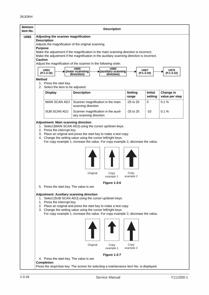
2KJ/2KH
U065 Adjusting the scanner magnificationDescriptionAdjusts the magnification of the original scanning.PurposeMake the adjustment if the magnification in the main scanning direction is incorrect.Make the adjustment if the magnification in the auxiliary scanning direction is incorrect.CautionAdjust the magnification of the scanner in the following order.
Method1. Press the start key.2. Select the item to be adjusted.
Adjustment: Main scanning direction1. Select [MAIN SCAN ADJ] using the cursor up/down keys.2. Press the interrupt key.3. Place an original and press the start key to make a test copy.4. Change the setting value using the cursor left/right keys.
For copy example 1, increase the value. For copy example 2, decrease the value.
Figure 1-3-65. Press the start key. The value is set.
Adjustment: Auxiliary scanning direction1. Select [SUB SCAN ADJ] using the cursor up/down keys.1. Press the interrupt key.2. Place an original and press the start key to make a test copy.3. Change the setting value using the cursor left/right keys.
For copy example 1, increase the value. For copy example 2, decrease the value.
Figure 1-3-74. Press the start key. The value is set.
CompletionPress the stop/clear key. The screen for selecting a maintenance item No. is displayed.
Maintenanceitem No. Description
U065(main scanning
direction)U053
(P.1-3-16)U067
(P.1-3-20)U065
(auxiliary scanning direction)
U070(P.1-3-22)
Display Description Settingrange
Initialsetting
Change invalue per step
MAIN SCAN ADJ Scanner magnification in the main scanning direction
-25 to 25 0 0.1 %
SUB SCAN ADJ Scanner magnification in the auxil-iary scanning direction
-25 to 25 -10 0.1 %
Original Copy
example 1
Copy
example 2
Original Copy
example 1
Copy
example 2
1-3-18 Service Manual Y111000-1

2KJ/2KH
U066 Adjusting the scanner leading edge registrationDescriptionAdjusts the scanner leading edge registration of the original scanning.PurposeMake the adjustment if there is a regular error between the leading edges of the copy image and original.Adjustment
1. Press the start key.2. Select the item to be adjusted using the cursor up/down keys.
3. Press the interrupt key.4. Place an original and press the start key to make a test copy.5. Change the setting value using the cursor left/right keys.
For copy example 1, increase the value. For copy example 2, decrease the value.
Figure 1-3-86. Press the start key. The value is set.
CautionCheck the copy image after the adjustment. If the image is still incorrect, perform the following adjustments in maintenance mode.
CompletionPress the stop/clear key. The screen for selecting a maintenance item No. is displayed.
Maintenanceitem No. Description
Display Description Settingrange
Initialsetting
Change invalue per step
ADJUST DATA 1 Scanner leading edge registration -32 to 20 0 0.17 mm
ADJUST DATA2 Scanner leading edge registration (rotate copying)
-20 to 20 0 0.084 mm
Original
Scanner leading edge registration
Copy
example 1
Copy
example 2
U066 U403(P.1-3-54)
U071(P.1-3-23)
U404(P.1-3-55)
1-3-19Y111000-1 Service Manual

2KJ/2KH
U067 Adjusting the scanner center lineDescriptionAdjusts the scanner center line of the original scanning.PurposeMake the adjustment if there is a regular error between the center lines of the copy image and original.Adjustment
1. Press the start key.2. Select the item to be adjusted using the cursor up/down keys.
3. Press the interrupt key.4. Place an original and press the start key to make a test copy.5. Change the setting value using the cursor left/right keys.
For copy example 1, decrease the value. For copy example 2, increase the value.
Figure 1-3-96. Press the start key. The value is set.
CautionCheck the copy image after the adjustment. If the image is still incorrect, perform the following adjustments in maintenance mode.
CompletionPress the stop/clear key. The screen for selecting a maintenance item No. is displayed.
Maintenanceitem No. Description
Display Description Settingrange
Initialsetting
Change invalue per step
ADJUST DATA 1 Scanner center line -39 to 39 -4 0.17 mm
ADJUST DATA 2 Scanner center line (rotate copying) -39 to 39 0 0.084 mm
Original Copy
example 1
Copy
example 2
Scanner center line
U067 U403(P.1-3-54)
U072(P.1-3-25)
U404(P.1-3-55)
1-3-20 Service Manual Y111000-1

2KJ/2KH
U068 Adjusting the scanning position for originals from the DPDescriptionAdjusts the position for scanning originals from the DP.PurposeUsed when the image fogging occurs because the scanning position is not proper when the DP is used. Run U071 to adjust the timing of DP leading edge when the scanning position is changed.Setting
1. Press the start key.2. Change the setting using the cursor left/right keys.
Increasing the value moves the image backward, and decreasing it moves the image forward. 3. Press the start key. The value is set.
SupplementWhile this maintenance item is being executed, copying from an original is available in interrupt copying mode(which is activated by pressing the interrupt key).
CompletionPress the stop/clear key. The screen for selecting a maintenance item No. is displayed.
Maintenanceitem No. Description
Description Setting range
Initial setting
Change in value per step
Starting position adjustment forscanning originals -17 to 17 0 0.17 mm
1-3-21Y111000-1 Service Manual

2KJ/2KH
U070 Adjusting the DP magnificationDescriptionAdjusts the DP original scanning speed.PurposeMake the adjustment if the magnification is incorrect in the auxiliary scanning direction when the optional DP is used.Adjustment
1. Press the start key.2. Select the item to be adjusted using the cursor up/down keys.
1. Press the interrupt key.2. Place an original on the DP and press the start key to make a test copy.3. Change the setting value using the cursor left/right keys.
For copy example 1, increase the value. For copy example 2, decrease the value.
Figure 1-3-10
4. Press the start key. The value is set.
CautionCheck the copy image after the adjustment. If the image is still incorrect, perform the following adjustments in maintenance mode.
CompletionPress the stop/clear key. The screen for selecting a maintenance item No. is displayed.
Maintenanceitem No. Description
Display Description Settingrange
Initialsetting
Change invalue per step
CONVEY SPEED 1
Magnification in the auxiliary scan-ning direction (first page)
-25 to 25 0 0.2 mm
CONVEY SPEED 2
Magnification in the auxiliary scan-ning direction (second page)
-25 to 25 0 0.2 mm
Original Copy
example 1
Copy
example 2
U070 U071(P.1-3-23)
U404(P.1-3-55)
1-3-22 Service Manual Y111000-1

2KJ/2KH
U071 Adjusting the DP scanning timingDescriptionAdjusts the DP original scanning timing.PurposeMake the adjustment if there is a regular error between the leading or trailing edges of the original and the copy image when the optional DP is used.Method
1. Press the start key.2. Select the item to be adjusted using the cursor up/down keys.
Adjustment: Leading edge registration1. Select [LEAD 1] or [LEAD 2] using the cursor up/down keys.2. Press the interrupt key.3. Place an original on the DP and press the start key to make a test copy.4. Change the setting value using the cursor left/right keys.
For copy example 1, increase the value. For copy example 2, decrease the value.
Figure 1-3-11
5. Press the start key. The value is set.
CautionCheck the copy image after the adjustment. If the image is still incorrect, perform the following adjustments in maintenance mode.
Maintenanceitem No. Description
Display Description Settingrange
Initialsetting
Change invalue per step
LEAD 1 Leading edge registration (first page) -32 to 22 0 0.2 mm
TRAIL 1 Trailing edge registration (first page) -22 to 32 0 0.2 mm
LEAD 2 Leading edge registration (second page) -32 to 22 0 0.2 mm
TRAIL 2 Trailing edge registration (second page) -22 to 32 0 0.2 mm
Original Copy
example 1
Copy
example 2
U071 U404(P.1-3-55)
1-3-23Y111000-1 Service Manual
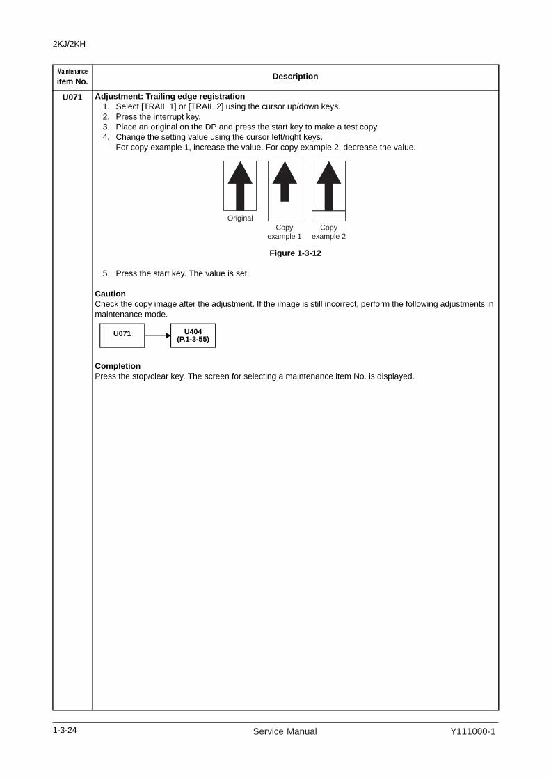
2KJ/2KH
U071 Adjustment: Trailing edge registration1. Select [TRAIL 1] or [TRAIL 2] using the cursor up/down keys.2. Press the interrupt key.3. Place an original on the DP and press the start key to make a test copy.4. Change the setting value using the cursor left/right keys.
For copy example 1, increase the value. For copy example 2, decrease the value.
Figure 1-3-12
5. Press the start key. The value is set.
CautionCheck the copy image after the adjustment. If the image is still incorrect, perform the following adjustments in maintenance mode.
CompletionPress the stop/clear key. The screen for selecting a maintenance item No. is displayed.
Maintenanceitem No. Description
Original
Copy
example 1
Copy
example 2
U071 U404(P.1-3-55)
1-3-24 Service Manual Y111000-1

2KJ/2KH
U072 Adjusting the DP center lineDescriptionAdjusts the scanning start position for the DP original.PurposeMake the adjustment if there is a regular error between the centers of the original and the copy image when the optional DP is used.Adjustment
1. Press the start key.2. Select the item to be adjusted using the cursor up/down keys.
3. Press the interrupt key.4. Place an original on the DP and press the start key to make a test copy.5. Change the setting value using the cursor left/right keys.
For copy example 1, increase the value. For copy example 2, decrease the value.
Figure 1-3-13
6. Press the start key. The value is set.
CautionCheck the copy image after the adjustment. If the image is still incorrect, perform the following adjustments in maintenance mode.
CompletionPress the stop/clear key. The screen for selecting a maintenance item No. is displayed.
Maintenanceitem No. Description
Display Description Settingrange
Initialsetting
Change invalue per step
1sided DP center line (simplex mode) -39 to 39 0 0.15 mm
2sided front DP center line (first page of duplex mode)
-39 to 39 0 0.15 mm
2sided back DP center line (second page of duplex mode)
-39 to 39 0 0.15 mm
Original Copy
example 1
Copy
example 2
U072 U404(P.1-3-55)
1-3-25Y111000-1 Service Manual
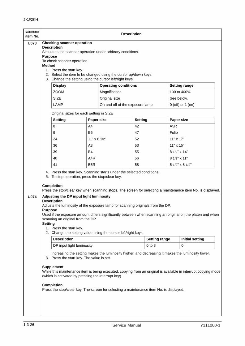
2KJ/2KH
U073 Checking scanner operationDescriptionSimulates the scanner operation under arbitrary conditions.PurposeTo check scanner operation.Method
1. Press the start key.2. Select the item to be changed using the cursor up/down keys.3. Change the setting using the cursor left/right keys.
Original sizes for each setting in SIZE
4. Press the start key. Scanning starts under the selected conditions.5. To stop operation, press the stop/clear key.
CompletionPress the stop/clear key when scanning stops. The screen for selecting a maintenance item No. is displayed.
U074 Adjusting the DP input light luminosityDescriptionAdjusts the luminosity of the exposure lamp for scanning originals from the DP.PurposeUsed if the exposure amount differs significantly between when scanning an original on the platen and when scanning an original from the DP.Setting
1. Press the start key.2. Change the setting value using the cursor left/right keys.
Increasing the setting makes the luminosity higher, and decreasing it makes the luminosity lower.3. Press the start key. The value is set.
SupplementWhile this maintenance item is being executed, copying from an original is available in interrupt copying mode(which is activated by pressing the interrupt key).
CompletionPress the stop/clear key. The screen for selecting a maintenance item No. is displayed.
Maintenanceitem No. Description
Display Operating conditions Setting range
ZOOM Magnification 100 to 400%
SIZE Original size See below.
LAMP On and off of the exposure lamp 0 (off) or 1 (on)
Setting Paper size Setting Paper size8 A4 42 A5R
9 B5 47 Folio
24 11" x 8 1/2" 52 11" x 17"
36 A3 53 11" x 15"
39 B4 55 8 1/2" x 14"
40 A4R 56 8 1/2" x 11"
41 B5R 58 5 1/2" x 8 1/2"
Description Setting range Initial setting
DP input light luminosity 0 to 8 0
1-3-26 Service Manual Y111000-1

2KJ/2KH
1-3-27
U076 Executing DP automatic adjustmentDescriptionUses a specified original and automatically adjusts the following items in the DP scanning section.Adjusting the DP magnification (U070)Adjusting the DP scanning timing (U071)Adjusting the DP center line (U072)When you run this maintenance mode, the preset values of U070, U071 and U072 will also be updated.PurposeTo perform automatic adjustment of various items in the DP scanning section.Method
1. Set a specified original (P/N: AVGR11211F) in the DP.Cut the trailing edge of the original.
Figure 1-3-14
2. Press the start key.3. Press the start key. Auto adjustment starts.
When adjustment is complete, each adjusted value is displayed.
If a problem occurs during auto adjustment, DATA: XX (XX is replaced by an error code) is displayed and operation stops. Should this happen, determine the details of the problem and either repeat the pro-cedure from the beginning, or adjust the remaining items manually by running the corresponding main-tenance items.
CompletionPress the stop/clear key after auto adjustment is complete. The screen for selecting a maintenance item isdisplayed.If the stop/clear key is pressed during auto adjustment, adjustment stops and no settings are changed.
Maintenanceitem No. Description
F
R
5 mm
149 ± 1 mm
74 ± 1 mm
Display Description
CONVEY SPEED DP magnification in the auxiliary scanning direction
LEAD EDGE ADJ DP leading edge registration
DP CENTER DP original center line
Y111000-1 Service Manual

2KJ/2KH
U087 Setting DP reading position modification operationDescriptionThe presence or absence of dust is determined by comparing the scan data of the original trailing edge and that taken after the original is conveyed past the DP original scanning position. If dust is identified, the DP original scanning position is adjusted for the following originals.PurposeWhen using DP, to solve the problem when black lines occurs due to the dust with respect to original reading position.Setting
1. Press the start key.2. Select ON or OFF using the cursor up/down keys.
Initial setting: ON3. Press the start key. The setting is set.
Setting the reference data for identifying dustAvailable only when the mode is turned on.
1. Change the setting using the cursor left/right keys.
ExampleThe figure indicates the density in 256 levels of gray (0: white, 255: black). When the setting is 35, data of the level of 35 or higher is regarded as dust and data of lower level is regarded as the background (scan data taken when there is no original).
2. Press the start key. The value is set.
CompletionPress the stop/clear key. The screen for selecting a maintenance item No. is displayed.
Maintenanceitem No. Description
Display DescriptionON DP scanning position adjust mode on
OFF DP scanning position adjust mode off
Description Setting range Initial setting
Minimum density to be regarded as dust 10 to 95 35
1-3-28 Service Manual Y111000-1

2KJ/2KH
U089 Outputting a MIP-PG patternDescriptionSelects and outputs the MIP-PG pattern created in the machine.PurposeTo check copier status other than scanner when adjusting image printing, using MIP-PG pattern output (with-out scanning).Method
1. Press the start key.2. Select the MIP-PG pattern to be output using the cursor up/down keys.
3. To change the output conditions of MONO-LEVEL and 1dot-LINE, use the cousor left/right keys to change the preset values and press the start key to register the setting.
4. Press the interrupt key.5. Press the start key. A MIP-PG pattern is output.
CompletionPress the stop/clear key. The screen for selecting a maintenance item No. is displayed.
Maintenanceitem No. Description
Display PG pattern to be output Purpose
GRAYSCALE To check the laser scanner unit engine output characteristics.
MONO-LEVEL To check the drum quality.
256-LEVEL To check resolutionreproducibility in printing.
1 dot-LINE To check fine line reproducibility.To adjust the position of the laser scanner unit (lateral squareness)
Description Setting range Initial setting
Output density of MONO-LEVEL 0 to 255 0
1dot-LINE 0 to 21 0
1-3-29Y111000-1 Service Manual
2KJ/2KH
1-3-30
U092 Adjusting the scanner automaticallyDescriptionMakes auto scanner adjustments in the order below using the specified original. Adjusting the scanner center line (U067)Adjusting the scanner leading edge registration (U066)Adjusting scanner magnification in the auxiliary direction (U065)When this maintenance item is performed, the settings in U065, U066 and U067 are also changed.Purpose Used to make respective auto adjustments for the scanner.Method
1. Place the specified original (P/N: AVGR05131K) on the contact glass.2. Press the start key.3. Press the start key. Auto adjustment starts.
When adjustment is complete, each adjusted value is displayed.
If a problem occurs during auto adjustment, DATA: XX (XX is replaced by an error code) is displayed and operation stops. Should this happen, determine the details of the problem and either repeat the pro-cedure from the beginning, or adjust the remaining items manually by running the corresponding main-tenance items.
Completion Press the stop/clear key after auto adjustment is complete. The screen for selecting a maintenance item No.is displayed.If the stop/clear key is pressed during auto adjustment, adjustment stops and no settings are changed.
Maintenanceitem No. Description
Display DescriptionSCN CENTER Scanner center line
SCN TIMING Scanner leading registration
SUB SCAN Scanner magnification in the auxiliary scanning direction
MAIN SCAN Scanner magnification in the main scanning direction
Service Manual Y111000-1

2KJ/2KH
U093 Setting the exposure density gradientDescriptionChanges the exposure density gradient in the manual density mode, depending on respective image quality modes.PurposeTo set how the image density is altered by a change of one step in the manual density adjustment for respec-tive image quality modes. Also used to make copy images darker or lighter.Method
1. Press the start key.2. Select the image quality mode using the cursor up/down keys.3. Press the start key. The setting screen for the selected item is displayed.
Setting: Density in text and photo mode1. Select the item to be set using the cursor up/down keys.2. Adjust the setting using the cursor left/right keys.
Increasing the setting makes the change in density larger, and decreasing it makes the change smaller.
Figure 1-3-15
3. Press the start key. The value is set.4. To return to the screen for selecting an item, press the stop/clear key.
Setting: Density in text mode1. Select the item to be set using the cursor up/down keys.2. Adjust the setting using the cursor left/right keys.
Increasing the setting makes the change in density larger, and decreasing it makes the change smaller.3. Press the start key. The value is set.4. To return to the screen for selecting an item, press the stop/clear key.
Maintenanceitem No. Description
Display DescriptionMIXED Density in the text and photo mode
TEXT Density in text mode
PHOTO Density in photo mode
FAX TEXT Density in the text in fax mode
FAX PHOTO Density in the photo in fax mode
Display Description Settingrange
Initialsetting
MIXED DARKER Change in density when manual density is set dark 0 to 3 0
MIXED LIGHTER Change in density when manual density is set light 0 to 3 0
Image density
Density adjustment
Dark
Light
Light Center Dark
Setting: 0Setting: 3
Set to DARKER
Set to LIGHTER
Display Description Settingrange
Initialsetting
TEXT DARKER Change in density when manual density is set dark 0 to 3 0
TEXT LIGHTER Change in density when manual density is set light 0 to 3 0
1-3-31Y111000-1 Service Manual

2KJ/2KH
U093 Setting: Density in photo mode 1. Select the item to be set using the cursor up/down keys.2. Adjust the setting using the cursor left/right keys.
Increasing the setting makes the change in density larger, and decreasing it makes the change smaller.3. Press the start key. The value is set.4. To return to the screen for selecting an item, press the stop/clear key.
Setting: Density in text in fax mode1. Select the item to be set using the cursor up/down keys.2. Adjust the setting using the cursor left/right keys.
Increasing the setting makes the change in density larger, and decreasing it makes the change smaller.3. Press the start key. The value is set.4. To return to the screen for selecting an item, press the stop/clear key.
Setting: Density in photo in fax mode1. Select the item to be set using the cursor up/down keys.2. Adjust the setting using the cursor left/right keys.
Increasing the setting makes the change in density larger, and decreasing it makes the change smaller.3. Press the start key. The value is set.4. To return to the screen for selecting an item, press the stop/clear key.
SupplementWhile this maintenance item is being executed, copying from an original is available in interrupt copying mode (which is activated by pressing the interrupt key).
CompletionPress the stop/clear key. The screen for selecting a maintenance item No. is displayed.
Maintenanceitem No. Description
Display Description Settingrange
Initialsetting
PHOTO DARKER Change in density when manual density is set dark 0 to 3 0
PHOTO LIGTER Change in density when manual density is set light 0 to 3 0
Display Description Settingrange
Initialsetting
FAX TEXT DARKER Change in density when manual density is set dark
0 to 4 2
FAX TEXT LIGHTER Change in density when manual density is set light
0 to 4 2
Display Description Settingrange
Initialsetting
FAX PHOTO DARKER Change in density when manual density is set dark
0 to 6 3
FAX PHOTO LIGTER Change in density when manual density is set light
0 to 6 3
1-3-32 Service Manual Y111000-1

2KJ/2KH
U099 Adjusting original size detectionDescriptionChecks the operation of the original size detection sensor and sets the sensing threshold value.PurposeTo adjust the sensitiveness of the sensor and size judgement time if the original size detection sensor mal-functions frequently due to incident light or the like.Method
1. Press the start key.2. Select the item using the cursor up/down keys.3. Press the start key. The screen for executing each item is displayed.
Method to display the data for the sensor1. Place the original and close the original cover or DP. 2. Press the start key. The detection sensor transmission data is displayed.
Figure 1-3-16
3. To return to the screen for selecting an item, press the stop/clear key.
Setting1. Select an item to be set using the cursor up/down keys.2. Adjust the setting using the cursor left/right keys.
3. Press the start key. The value is set. 4. To return to the screen for selecting an item, press the stop/clear key.
Completion Press the stop/clear key. The screen for selecting a maintenance item No. is displayed.
Maintenanceitem No. Description
Display Description
DATA Displaying detection sensor transmission data
B/W LEVEL Setting detection sensor threshold valueSetting original size judgment time
: 123 123 123
: 123 123 123
: 255 255 255
Rear of machine
Center of machine
Front of machine
Display Description Setting range
Initial setting
LEVEL Detection sensor threshold value 0 to 255 170
WAIT TIME Original size judgment time 0 to 100 30
A4R AREA Threshold value in the main scan direction for A4R detection
220 (mm)/ 240 (mm)
240
ORIG AREA Original size detection position display (mm) 0 to 350 -
SIZE Detected original size display 0 to 63 -
1-3-33Y111000-1 Service Manual

2KJ/2KH
U100 Setting the main high voltageDescriptionChanges the surface potential by changing the grid control voltage. Also performs main charging. Also changes the setting of main charging copy quantity correction.PurposeTo set the surface potential or check main charging. Also used when reentering data after initializing the set data.Start
1. Press the start key.2. Select the item using the cursor up/down keys.
Method for main charger output1. Select [MC ON] or [LASER ON/OFF] using the cursor up/down keys.2. Press the start key. The selected operation starts.3. To stop operation, press the stop/clear key.
Setting the grid control voltage1. Select [MC DATA] using the cursor up/down keys.2. Change the setting using the cursor left/right keys.
Increasing the setting makes the surface potential higher, and decreasing it makes the potential lower. 3. Press the start key. The value is set.
Setting the main charging copy quantity correction1. Select the item using the cursor up/down keys.2. Change the setting using the cursor left/right keys.
Copy interval: Sets the time interval from the previous copying. If the time from the previous copying exceeds this preset value, the copy quantity counter will be reset. Copy quantity: Sets the copy quantity from which copy quantity correction starts. When the copy quan-tity counter reaches this preset value, correction will start.Correction amount: Sets the correction amount for copy quantity correction.Set the values in the range from 5 to 120 minutes for copy interval, from 10 to 2,000 sheets for copy quantity, and from 5 to 50 bits for correction amount.
3. Press the start key. The value is set.
CompletionPress the stop/clear key when main charger output stops while a selection item is displayed. The screen for selecting a maintenance item No. is displayed.
Maintenanceitem No. Description
Display Description
MC DATA Changing the grid control voltage
MC ON Turning the main charger on
LASER ON/OFF Turning the main charger on and the laser scanner unit on and off
INTERVAL Main charging copy quantity correction, copy interval
COPY CNT Main charging copy quantity correction, copy quantity
MC ADJUST Main charging copy quantity correction, correction amount
Description Setting range Initial setting
Grid control voltage 0 to 255 107
Display Description Setting range Initial settingINTERVAL Copy interval 1 to 255 (minute) 60COPY CNT Copy quantity 1 to 255 (10 sheets) 50MC ADJUST Correction amount 0 to 50 (bit) 10
1-3-34 Service Manual Y111000-1

2KJ/2KH
U101 Setting the other high voltagesDescriptionChanges the developing bias voltage and transfer/separation voltage. Purpose To check the developing bias and the transfer/separation voltage or to take measures against drop of imagedensity or background fog. Method
1. Press the start key.2. Select the item to be set using the cursor up/down keys.3. Press the start key. The screen for executing each item is displayed.
Setting the developing bias 1. Select the item to be set using the cursor up/down keys.2. Change the setting using the cursor left/right keys.
Increasing the setting makes the image lighter; decreasing it makes the image darker. 3. Press the start key. The value is set.
Setting the transfer voltage1. Select the item to be set using the cursor up/down keys.2. Change the setting using the cursor left/right keys.
3. Press the start key. The value is set.
Setting the separation voltage 1. Select the item to be set using the cursor up/down keys.2. Change the setting using the cursor left/right keys.
3. Press the start key. The value is set.
SupplementWhile this maintenance item is being executed, copying from an original is available in interrupt copying mode (which is activated by pressing the interrupt key).Completion Press the stop/clear key. The screen for selecting a maintenance item No. is displayed.
Maintenanceitem No. Description
Display Description
DEV Setting the developing bias
TC Setting the transfer voltage
SC Setting the separation voltage
Display Description Setting range Initial setting
BIAS C Developing bias clock frequency (copier mode) 2 to 255 27
DUTY C Developing bias clock duty (copier mode) 1 to 99 45
BIAS P Developing bias clock frequency (printer mode) 2 to 255 22
DUTY P Developing bias clock duty (printer mode) 1 to 99 45
Display Description Setting range Initial setting
TC DATA1 Transfer control voltage (large size) 0 to 255 123
TC DATA2 Transfer control voltage (small size) 0 to 255 126
OFF TIMING Transfer charging output OFF timing 0 to 255 33
ON TIMING Transfer charging output ON timing 0 to 255 31
Display Description Setting range Initial setting
SC SEL Separation control voltage 0 to 2 1
SC ON TIMING Separation charging output ON timing 0 to 255 20
SC OFF TIMING Separation charging output OFF timing 0 to 255 42
SC MODE Separation control mode 0 to 3 2
1-3-35Y111000-1 Service Manual

2KJ/2KH
U110 Checking the drum count DescriptionDisplays the drum counts for checking.PurposeTo check the drum status..Method
1. Press the start key. The drum counter count is displayed.CompletionPress the stop/clear key. The screen for selecting a maintenance item No. is displayed.
U130 Initial setting for the developing unitDescriptionReplenishes toner to the developing unit to a certain level from the toner container that has been installed.PurposeTo operate when installing the machine or replacing the developing unit.Method
1. Press the start key.1. Select [EXECUTE] using the cursor up/down keys.2. Press the start key. Installation of toner starts and time (minutes) is indicated until the installation ends.3. When the installation is complete, [FINISHED] will be displayed if the installation is successful or [NG]
will be displayed if it has failed. If [NG] is displayed, check to see if the toner container contains toner and to see if the toner container sensor malfunctions and then try again.
CompletionPress the stop/clear key after operation is complete. The screen for selecting a maintenance item No. is dis-played.
Maintenanceitem No. Description
1-3-36 Service Manual Y111000-1

2KJ/2KH
U144 Setting toner loading operationDescriptionSets toner loading operation after completion of copying.PurposeTo set whether or not toner is loaded on the drum after low density copying. Normally no change is necessary from the initial setting.Setting
1. Press the start key.2. Select ON or OFF using the cursor up/down keys.
Initial setting: OFF 3. Press the start key. The value is set.
SettingAvailable only when the setting is on.
1. Select the item using the cursor up/down keys.2. Change the setting using the cursor left/right keys.
3. Press the start key. The value is set.
CompletionPress the stop/clear key. The screen for selecting a maintenance item No. is displayed.
U150 Checking sensors for tonerDescriptionDisplays the on-off status of sensor related to toner.PurposeTo check if the sensor operate correctly.Method
1. Press the start key.2. Turn sensor on and off manually to check the status.
When the on-status of a sensor is detected, that sensor is displayed in reverse.
CompletionPress the stop/clear key. The screen for selecting a maintenance item No. is displayed.
Maintenanceitem No. Description
Display Description
ON Toner loaded
OFF Toner not loaded
Display Description Setting range Initial settingCOUNT Number of pages set 1 to 50 5
PERCENT Printing ratio 10 to 40 30
Display Sensor
CONTAINER SENSOR Toner container sensor (TCS)
1-3-37Y111000-1 Service Manual

2KJ/2KH
U157 Checking/clearing the developing drive timeDescriptionDisplays the developing drive time for checking, or clearing a figure, which is used as a reference when cor-recting the toner control.PurposeTo check the developing drive time after replacing the developing unit.Method
1. Press the start key. The developing drive time is displayed in minutes.Setting
1. Select [TIME(M)] using the cursor up/down keys.2. Enter a drive time (in minutes) using the numeric key.3. Press the start key. The time is set.
Clearing1. Select [CLEAR] using the cursor up/down keys.2. Press the start key. The time is cleared.
CompletionPress the stop/clear key. The screen for selecting a maintenance item No. is displayed.
U158 Checking the developing countDescriptionDisplays the developing count for checking.PurposeTo check the developing count after replacing the developing unit.Method
1. Press the start key. The developing counter count is displayed.Setting
1. Select [COUNT] using the cursor up/down keys.2. Change the count using the numeric key.3. Press the start key. The count is set.
Clearing1. Select [CLEAR] using the cursor up/down keys.2. Press the start key. The count is cleared.
CompletionPress the stop/clear key. The screen for selecting a maintenance item No. is displayed.
U161 Setting the fuser control temperatureDescriptionChanges the fuser control temperature.PurposeNormally no change is necessary. However, can be used to prevent curling or creasing of paper, or solve a fuser problem on thick paper.Method
1. Press the start key.2. Select the item to be set using the cursor up/down keys.3. Change the setting using the cursor left/right keys.
4. Press the start key. The value is set.CompletionPress the stop/clear key. The screen for selecting a maintenance item No. is displayed.
Maintenanceitem No. Description
Display Description Setting range Initial setting1ST TEMP Primary stabilization fixing temperature 120 to 185 145
2ND TEMP Secondary stabilization fixing temperature 120 to 185 165
COPY TEMP1 Copying operation temperature 1 160 to 220 175
COPY TEMP2 Copying operation temperature 2 160 to 220 185
UP TEMP Step-up operation temperature 1 to 99 1
DOWN TEMP Step-down operation temperature 1 to 99 2
1-3-38 Service Manual Y111000-1

2KJ/2KH
U162 Stabilizing fixing forcibly DescriptionStops the stabilization fixing drive forcibly, regardless of fixing temperature. PurposeTo forcibly stabilize the machine before the fixing section reaches stabilization temperature. Method
1. Press the start key.2. Press the start key. The forced stabilization mode is entered, and stabilization operation stops regard-
less of fixing temperature. The screen for selecting a maintenance item No. is displayed. To exit the forced stabilization mode, turn the power off and on.
CompletionPress the stop/clear key. The screen for selecting a maintenance item No. is displayed.
U163 Resetting the fuser problem dataDescriptionResets the detection of a service call code indicating a problem in the fuser section. PurposeTo prevent accidents due to an abnormally high fuser temperature. Method
1. Press the start key.2. Press [EXECUTE] using the cursor up/down keys.3. Press the start key. The fuser problem data is initialized.4. The machine automatically returns to the same status as when the main power switch is turned on.
U167 Checking/clearing the fuser countsDescriptionDisplays and clears the fuser counts for checking.PurposeTo check or clear the fuser counts after replacing the fuser unit.Method
1. Press the start key. The fuser counts is displayed.Setting
1. Select [COUNT] using the cursor up/down keys.2. Change the count using the numeric key.3. Press the start key. The count is set.
Clearing1. Select [CLEAR] using the cursor up/down keys.2. Press the start key. The count is cleared.
CompletionPress the stop/clear key. The screen for selecting a maintenance item No. is displayed.
Maintenanceitem No. Description
1-3-39Y111000-1 Service Manual
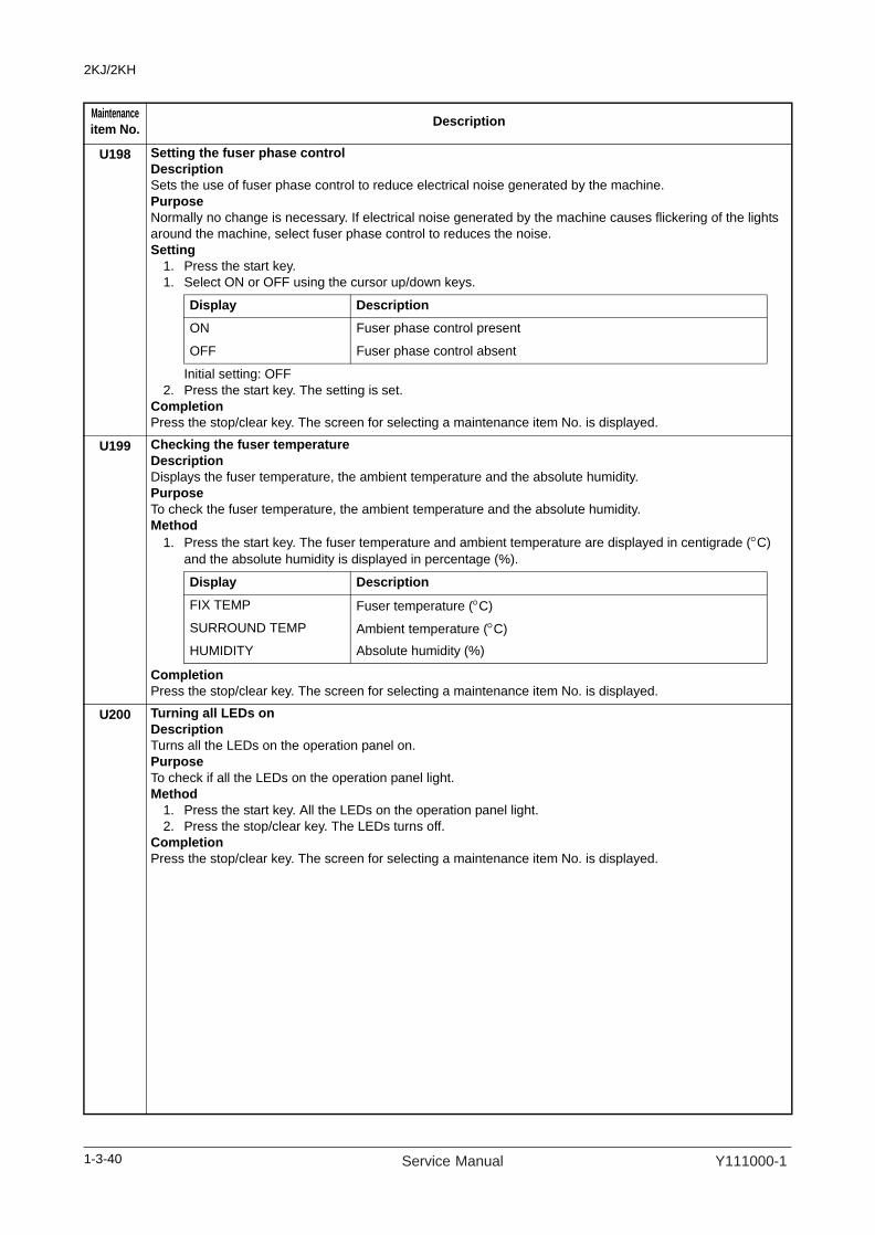
2KJ/2KH
U198 Setting the fuser phase controlDescriptionSets the use of fuser phase control to reduce electrical noise generated by the machine.PurposeNormally no change is necessary. If electrical noise generated by the machine causes flickering of the lights around the machine, select fuser phase control to reduces the noise.Setting
1. Press the start key.1. Select ON or OFF using the cursor up/down keys.
Initial setting: OFF2. Press the start key. The setting is set.
CompletionPress the stop/clear key. The screen for selecting a maintenance item No. is displayed.
U199 Checking the fuser temperatureDescriptionDisplays the fuser temperature, the ambient temperature and the absolute humidity. PurposeTo check the fuser temperature, the ambient temperature and the absolute humidity. Method
1. Press the start key. The fuser temperature and ambient temperature are displayed in centigrade (°C) and the absolute humidity is displayed in percentage (%).
Completion Press the stop/clear key. The screen for selecting a maintenance item No. is displayed.
U200 Turning all LEDs onDescriptionTurns all the LEDs on the operation panel on.PurposeTo check if all the LEDs on the operation panel light.Method
1. Press the start key. All the LEDs on the operation panel light.2. Press the stop/clear key. The LEDs turns off.
Completion Press the stop/clear key. The screen for selecting a maintenance item No. is displayed.
Maintenanceitem No. Description
Display Description
ON Fuser phase control present
OFF Fuser phase control absent
Display Description
FIX TEMP Fuser temperature (°C) SURROUND TEMP Ambient temperature (°C)HUMIDITY Absolute humidity (%)
1-3-40 Service Manual Y111000-1

2KJ/2KH
U202 Setting the KMAS host monitoring systemDescriptionInitializes or operates the KMAS host monitoring system.This is an optional device which is currently supported only by Japanese specification machines, so no setting is necessary.
U203 Checking DP operationDescriptionSimulates the original conveying operation separately in the DP.PurposeTo check the DP operation.Method
1. Press the start key.2. Place an original in the DP if running this simulation with paper.3. Select the item to be operated using the cursor up/down keys.
4. Press the start key. The operation starts.5. To stop continuous operation, press the stop/clear key.
CompletionPress the stop/clear key. The screen for selecting a maintenance item No. is displayed.
U204 Setting the presence or absence of a key card or key counterDescriptionSets the presence or absence of the optional key card or key counter.PurposeTo run this maintenance item if a key card or key counter is installed.Setting
1. Press the start key. 2. Select the optional counter to be installed using the cursor up/down keys.
3. Press the start key. The setting is set.Completion Press the stop/clear key. The screen for selecting a maintenance item No. is displayed.
Maintenanceitem No. Description
Display OperationADP With paper, single-sided original
RADP With paper, double-sided original
ADP (NON P) Without paper, single-sided original (continuous operation)
RADP (NON P) Without paper, double-sided original (continuous operation)
Display Description
OFF Not installed
KEY-CARD The key card is installed
KEY-COUNTER The key counter is installed
1-3-41Y111000-1 Service Manual

2KJ/2KH
U207 Checking the operation panel keysDescriptionChecks operation of the operation panel keys.PurposeTo check operation of all the keys and LEDs on the operation panel.Method
1. Press the start key. The screen for executing is displayed.2. COUNT1 is displayed and the leftmost LED on the operation panel lights.3. As the keys lined up in the same line as the lit indicator are pressed in the order from the top to the bot-
tom, the figure shown on the touch panel increases in increments of 1. When all the keys in that line are pressed and if there are any LEDs corresponding to the keys in the line on the immediate right, the top LED in that line will light.
4. When all the keys on the operation panel have been pressed, all the LEDs light for up to 10 seconds. CompletionPress the stop/clear key. The screen for selecting a maintenance item No. is displayed.
U233 Limiting job separator outputDescriptionSets a limit of number of output pages from the job separator.PurposeSettings may be modified if curled paper is output from the job separator.Setting
1. Press the start key.2. Select the mode using the cursor up/down keys.
Initial setting: MODE03. Press the start key. The setting is set.
CompletionPress the stop/clear key. The screen for selecting a maintenance item No. is displayed.
Maintenanceitem No. Description
Display Description
MODE 0 All sizes: 100 sheets
MODE 1 A3/Ledger sizes: 50, other sizes: 100
1-3-42 Service Manual Y111000-1
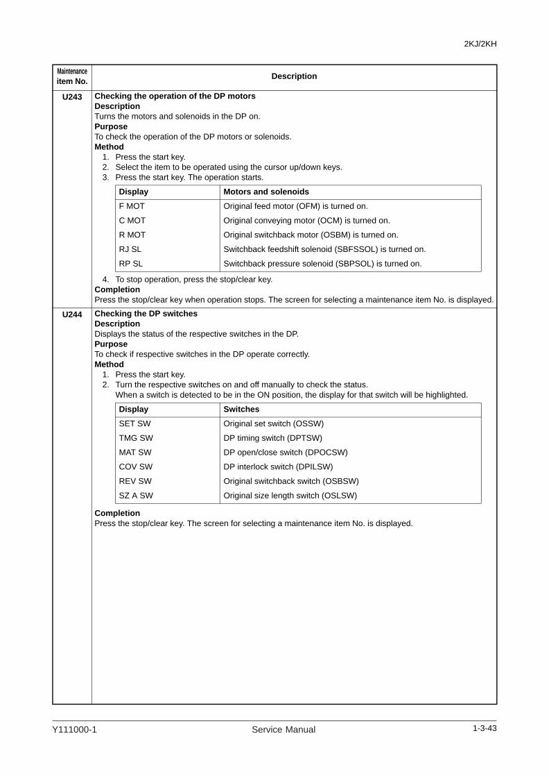
2KJ/2KH
U243 Checking the operation of the DP motorsDescriptionTurns the motors and solenoids in the DP on.PurposeTo check the operation of the DP motors or solenoids.Method
1. Press the start key.2. Select the item to be operated using the cursor up/down keys.3. Press the start key. The operation starts.
4. To stop operation, press the stop/clear key.Completion Press the stop/clear key when operation stops. The screen for selecting a maintenance item No. is displayed.
U244 Checking the DP switchesDescriptionDisplays the status of the respective switches in the DP.PurposeTo check if respective switches in the DP operate correctly.Method
1. Press the start key.2. Turn the respective switches on and off manually to check the status.
When a switch is detected to be in the ON position, the display for that switch will be highlighted.
CompletionPress the stop/clear key. The screen for selecting a maintenance item No. is displayed.
Maintenanceitem No. Description
Display Motors and solenoids
F MOT Original feed motor (OFM) is turned on.
C MOT Original conveying motor (OCM) is turned on.
R MOT Original switchback motor (OSBM) is turned on.
RJ SL Switchback feedshift solenoid (SBFSSOL) is turned on.
RP SL Switchback pressure solenoid (SBPSOL) is turned on.
Display Switches
SET SW Original set switch (OSSW)
TMG SW DP timing switch (DPTSW)
MAT SW DP open/close switch (DPOCSW)
COV SW DP interlock switch (DPILSW)
REV SW Original switchback switch (OSBSW)
SZ A SW Original size length switch (OSLSW)
1-3-43Y111000-1 Service Manual
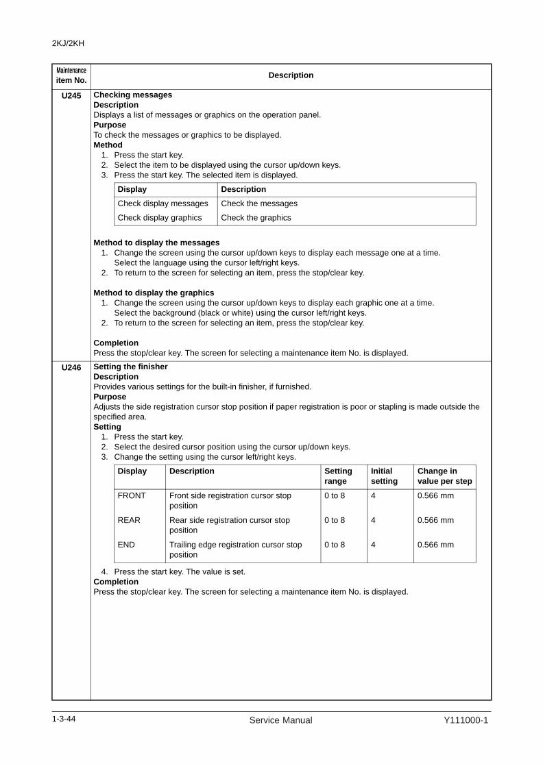
2KJ/2KH
U245 Checking messagesDescriptionDisplays a list of messages or graphics on the operation panel. PurposeTo check the messages or graphics to be displayed. Method
1. Press the start key. 2. Select the item to be displayed using the cursor up/down keys.3. Press the start key. The selected item is displayed.
Method to display the messages1. Change the screen using the cursor up/down keys to display each message one at a time.
Select the language using the cursor left/right keys.2. To return to the screen for selecting an item, press the stop/clear key.
Method to display the graphics1. Change the screen using the cursor up/down keys to display each graphic one at a time.
Select the background (black or white) using the cursor left/right keys.2. To return to the screen for selecting an item, press the stop/clear key.
CompletionPress the stop/clear key. The screen for selecting a maintenance item No. is displayed.
U246 Setting the finisherDescriptionProvides various settings for the built-in finisher, if furnished.PurposeAdjusts the side registration cursor stop position if paper registration is poor or stapling is made outside the specified area.Setting
1. Press the start key.2. Select the desired cursor position using the cursor up/down keys.3. Change the setting using the cursor left/right keys.
4. Press the start key. The value is set.CompletionPress the stop/clear key. The screen for selecting a maintenance item No. is displayed.
Maintenanceitem No. Description
Display Description
Check display messages Check the messages
Check display graphics Check the graphics
Display Description Settingrange
Initialsetting
Change invalue per step
FRONT Front side registration cursor stop position
0 to 8 4 0.566 mm
REAR Rear side registration cursor stop position
0 to 8 4 0.566 mm
END Trailing edge registration cursor stop position
0 to 8 4 0.566 mm
1-3-44 Service Manual Y111000-1

2KJ/2KH
U249 Checking the paper ejection to optional devicesDescriptionEject paper to the optional ejection device. When the job separator or the built-in finisher is connected, thisoperation cannot be run.PurposeTo check that paper is ejected properly to the optional ejection device.Method
1. While pressing the feedshift switch by your hand, press the start key. Paper transfer operation starts.
CompletionPress the stop/clear key. The screen for selecting a maintenance item No. is displayed.
U250 Setting the maintenance cycleDescriptionDisplays and changes the maintenance cycle.PurposeTo check and change the maintenance cycle.Method
1. Press the start key. The currently set maintenance cycle is displayed.Setting
1. Change the setting using the numeric keys.
2. Press the start key. The value is set.Clearing
1. Press the reset key.2. Press the start key. The count is cleared.
CompletionPress the stop/clear key. The screen for selecting a maintenance item No. is displayed.
U251 Checking/clearing the maintenance countDescriptionDisplays, clears and changes the maintenance count.PurposeTo check the maintenance count. Also to clear the count during maintenance service.Method
1. Press the start key. The maintenance count is displayed.Setting
1. Select [COUNT] using the cursor up/down keys.2. Change the count using the numeric key.3. Press the start key. The count is set.
Clearing1. Select [CLEAR] using the cursor up/down keys.2. Press the start key. The count is cleared.
CompletionPress the stop/clear key. The screen for selecting a maintenance item No. is displayed.
Maintenanceitem No. Description
Description Setting range Initial setting
Maintenance cycle 0 to 9999999 150000
1-3-45Y111000-1 Service Manual
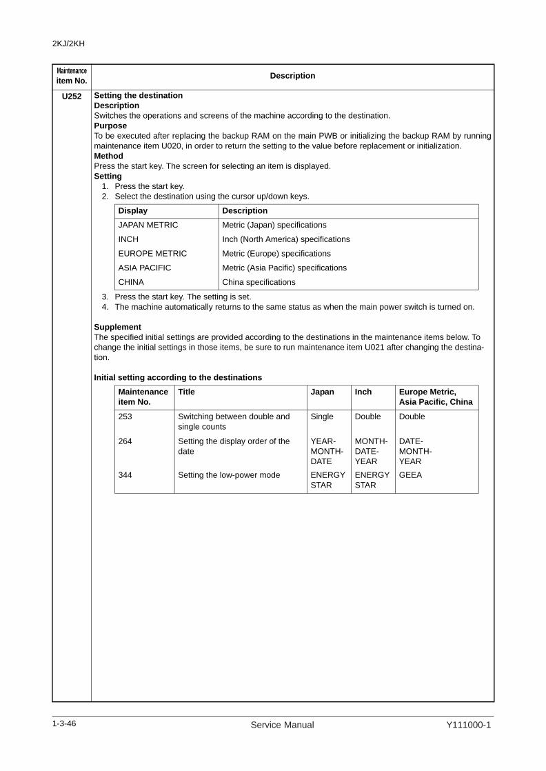
2KJ/2KH
U252 Setting the destinationDescriptionSwitches the operations and screens of the machine according to the destination.PurposeTo be executed after replacing the backup RAM on the main PWB or initializing the backup RAM by runningmaintenance item U020, in order to return the setting to the value before replacement or initialization.MethodPress the start key. The screen for selecting an item is displayed.Setting
1. Press the start key.2. Select the destination using the cursor up/down keys.
3. Press the start key. The setting is set.4. The machine automatically returns to the same status as when the main power switch is turned on.
SupplementThe specified initial settings are provided according to the destinations in the maintenance items below. To change the initial settings in those items, be sure to run maintenance item U021 after changing the destina-tion.
Initial setting according to the destinations
Maintenanceitem No. Description
Display DescriptionJAPAN METRIC Metric (Japan) specifications
INCH Inch (North America) specifications
EUROPE METRIC Metric (Europe) specifications
ASIA PACIFIC Metric (Asia Pacific) specifications
CHINA China specifications
Maintenanceitem No.
Title Japan Inch Europe Metric,Asia Pacific, China
253 Switching between double and single counts
Single Double Double
264 Setting the display order of the date
YEAR-MONTH-DATE
MONTH-DATE-YEAR
DATE-MONTH-YEAR
344 Setting the low-power mode ENERGY STAR
ENERGY STAR
GEEA
1-3-46 Service Manual Y111000-1
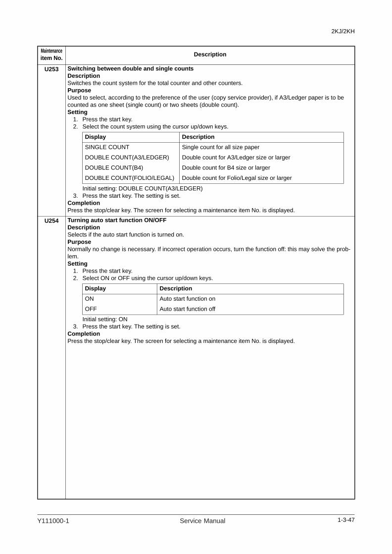
2KJ/2KH
U253 Switching between double and single countsDescriptionSwitches the count system for the total counter and other counters.PurposeUsed to select, according to the preference of the user (copy service provider), if A3/Ledger paper is to be counted as one sheet (single count) or two sheets (double count).Setting
1. Press the start key.2. Select the count system using the cursor up/down keys.
Initial setting: DOUBLE COUNT(A3/LEDGER)3. Press the start key. The setting is set.
CompletionPress the stop/clear key. The screen for selecting a maintenance item No. is displayed.
U254 Turning auto start function ON/OFFDescriptionSelects if the auto start function is turned on.PurposeNormally no change is necessary. If incorrect operation occurs, turn the function off: this may solve the prob-lem.Setting
1. Press the start key.2. Select ON or OFF using the cursor up/down keys.
Initial setting: ON3. Press the start key. The setting is set.
CompletionPress the stop/clear key. The screen for selecting a maintenance item No. is displayed.
Maintenanceitem No. Description
Display Description
SINGLE COUNT Single count for all size paper
DOUBLE COUNT(A3/LEDGER) Double count for A3/Ledger size or larger
DOUBLE COUNT(B4) Double count for B4 size or larger
DOUBLE COUNT(FOLIO/LEGAL) Double count for Folio/Legal size or larger
Display Description
ON Auto start function on
OFF Auto start function off
1-3-47Y111000-1 Service Manual

2KJ/2KH
U260 Selecting the timing for copy countingDescriptionChanges the copy count timing for the total counter and other counters.PurposeTo be set according to user (copy service provider) request.If a paper jam occurs frequently in the optional document finisher when the number of copies is counted at the time of paper ejection, copies are provided without copy counts. The copy service provider cannot charge for such copying. To prevent this, the copy timing should be made earlier.If a paper jam occurs frequently in the paper conveying or fuser sections when the number of copies is counted before the paper reaches those sections, copying is charged without a copy being made. To prevent this, the copy timing should be made later.Setting
1. Press the start key.2. Select the copy count timing using the cursor up/down keys.
Initial setting: EJECT3. Press the start key. The setting is set.
CompletionPress the stop/clear key. The screen for selecting a maintenance item No. is displayed.
U264 Setting the display order of the dateDescriptionSelects year, month and day as the order of that appears on lists, etc.PurposeSet according to the user preference.Setting
1. Press the start key.2. Select the desired order using the cursor up/down keys.
Initial setting: MONTH-DATE-YEAR (for the inch specifications) DATE-MONTH-YEAR (for the metric specifications)
3. Press the start key. The setting is set.CompletionPress the stop/clear key. The screen for selecting a maintenance item No. is displayed.
Maintenanceitem No. Description
Display DescriptionFEED When secondary paper feed starts
EJECT When the paper is ejected
Display SettingYEAR-MONTH-DATE Year/Month/Day
MONTH-DATE-YEAR Month/Day/Year
DATE-MONTH-YEAR Day/Month/Year
1-3-48 Service Manual Y111000-1

2KJ/2KH
U265 Setting OEM purchaser codeDescriptionSets the OEM purchaser code.PurposeSets the code when replacing the main PWB and the like.Setting
1. Press the start key.2. Change the preset value using the numeric keys or cursor left/right keys.3. Press the start key. The setting is set.
CompletionPress the stop/clear key. The screen for selecting a maintenance item No. is displayed.
U277 Setting auto application change timeDescriptionSets the time that passes until the machine starts automatically printing after completing copying or operation when the machine is used as a printer.PurposeAccording to user request, changes the setting.Setting
1. Press the start key.2. Change the setting using the cursor left/right keys.
The setting can be changed by 30 s per step.3. Press the start key. The value is set.
CompletionPress the stop/clear key. The screen for selecting a maintenance item No. is displayed.
U326 Setting the black line cleaning indicationDescriptionSets whether to display the cleaning guidance when detecting the black line.PurposeDisplays the cleaning guidance in order to make the call for service with the black line decrease by the rubbish on the platen when scanning from the DP.Setting
1. Press the start key.2. Select ON or OFF using the cursor up/down keys.
Initial setting: ON3. Press the start key. The setting is set.
CompletionPress the stop/clear key. The screen for selecting a maintenance item No. is displayed.
Maintenanceitem No. Description
Description Setting range Default setting
Switching time 30 to 270 (s) 30 (s)
Display Description
ON Displays the cleaning guidance
OFF Not to display the cleaning guidance
1-3-49Y111000-1 Service Manual
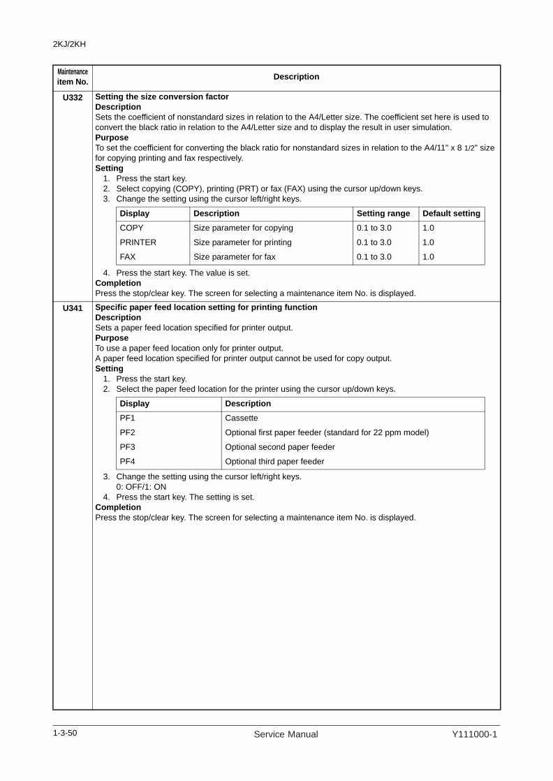
2KJ/2KH
U332 Setting the size conversion factor DescriptionSets the coefficient of nonstandard sizes in relation to the A4/Letter size. The coefficient set here is used to convert the black ratio in relation to the A4/Letter size and to display the result in user simulation.PurposeTo set the coefficient for converting the black ratio for nonstandard sizes in relation to the A4/11" x 8 1/2" size for copying printing and fax respectively.Setting
1. Press the start key.2. Select copying (COPY), printing (PRT) or fax (FAX) using the cursor up/down keys.3. Change the setting using the cursor left/right keys.
4. Press the start key. The value is set.CompletionPress the stop/clear key. The screen for selecting a maintenance item No. is displayed.
U341 Specific paper feed location setting for printing functionDescriptionSets a paper feed location specified for printer output.PurposeTo use a paper feed location only for printer output.A paper feed location specified for printer output cannot be used for copy output.Setting
1. Press the start key.2. Select the paper feed location for the printer using the cursor up/down keys.
3. Change the setting using the cursor left/right keys.0: OFF/1: ON
4. Press the start key. The setting is set.CompletionPress the stop/clear key. The screen for selecting a maintenance item No. is displayed.
Maintenanceitem No. Description
Display Description Setting range Default settingCOPY Size parameter for copying 0.1 to 3.0 1.0
PRINTER Size parameter for printing 0.1 to 3.0 1.0
FAX Size parameter for fax 0.1 to 3.0 1.0
Display DescriptionPF1 Cassette
PF2 Optional first paper feeder (standard for 22 ppm model)
PF3 Optional second paper feeder
PF4 Optional third paper feeder
1-3-50 Service Manual Y111000-1

2KJ/2KH
U342 Setting the ejection restrictionDescriptionSets or cancels the restriction on the number of sheets to be ejected continuously when the internal eject tray is selected as the eject location.PurposeAccording to user request, sets or cancels restriction on the number of sheets.Setting
1. Press the start key.2. Select ON or OFF using the cursor up/down keys.
Initial setting: ONDetails of restriction (number of sheets to be ejected continuously after the start key is pressed)
3. Press the start key. The setting is set.CompletionPress the stop/clear key. The screen for selecting a maintenance item No. is displayed.
U343 Switching between duplex/simplex copy modeDescriptionSwitches the initial setting between duplex and simplex copy.PurposeTo be set according to frequency of use: set to the more frequently used mode.Setting
1. Press the start key.2. Select ON or OFF using the cursor up/down keys.
Initial setting: OFF 3. Press the start key. The setting is set.
CompletionPress the stop/clear key. The screen for selecting a maintenance item No. is displayed.
Maintenanceitem No. Description
Display Description
ON Sets restriction on the number of sheets
OFF Cancels restriction on the number of sheets
Condition Number of sheets
When no optional ejection device is installed 250
When the job separator is installed 150
When the built-in finisher is installed 100
Display Description
ON Duplex copy
OFF Simplex copy
1-3-51Y111000-1 Service Manual

2KJ/2KH
U344 Setting the low-power modeDescriptionChanges the control for low-power mode.PurposeAccording to user request, selects which has priority, the recovery time from low-power or energy saver.Setting
1. Press the start key.2. Select control mode using the cursor up/down keys.
Initial setting: ENERGY STAR (inch specifications)/GEEA (metric specifications)3. Press the start key. The setting is set.
CompletionPress the stop/clear key. The screen for selecting a maintenance item No. is displayed.
U345 Setting the value for maintenance due indicationDescriptionSets when to display a message notifying that the time for maintenance is about to be reached, by setting the number of copies that can be made before the current maintenance cycle ends.When the difference between the number of copies of the maintenance cycle and that of the maintenance count reaches the set value, the message is displayed.PurposeTo change the time for maintenance due indication.Setting
1. Press the start key.2. Change the setting using the numeric keys.
3. Press the start key. The value is set.CompletionPress the stop/clear key. The screen for selecting a maintenance item No. is displayed.
Maintenanceitem No. Description
Display DescriptionENERGY STAR STAR The fixing control temperature is lowered by 20°C/68°F and
forced stabilization is performed 30 seconds after exiting preheat.GEEA The fixing control temperature is lowered by 15°C/59°F and forced
stabilization is performed 30 seconds after exiting preheat.
Display Description Setting range
COUNT Time for maintenance due indication (Remaining number of copies that can be made before the current maintenance cycle ends)
0 to 9999
1-3-52 Service Manual Y111000-1

2KJ/2KH
U402 Adjusting margins of image printingDescriptionAdjusts margins for image printing.PurposeMake the adjustment if margins are incorrect.Adjustment
1. Press the start key.2. Select the item to be adjusted using the cursor up/down keys.
3. Press the interrupt key.4. Press the start key to output a test pattern.5. Change the setting value using the cursor left/right keys.
Increasing the value makes the margin wider, and decreasing it makes the margin narrower.
Figure 1-3-17
6. Press the start key. The value is set.
CautionCheck the copy image after the adjustment. If the image is still incorrect, perform the following adjustments in maintenance mode.
CompletionPress the stop/clear key. The screen for selecting a maintenance item No. is displayed.
Maintenanceitem No. Description
Display Description Settingrange
Initialsetting
Change invalue per step
LEAD Printer leading edge margin 0 to 10.0 3.0 0.1 mm
AC Printer left and right margin -3.4 to 10.0 3.0 0.1 mm
TRAIL Printer trailing edge margin -5.0 to 10.0 4.0 0.1 mm
Printer leading edge margin
(3.0±1.0 mm)
Printerleft margin
Printerright margin
Printer trailing edge margin
(3.0±1.0 mm)
(2.5±1.0 mm) (2.5±1.0 mm)
U402 U403(P.1-3-54)
U404(P.1-3-55)
1-3-53Y111000-1 Service Manual

2KJ/2KH
U403 Adjusting margins for scanning an original on the platenDescriptionAdjusts margins for scanning the original on the platen.PurposeMake the adjustment if margins are incorrect.Adjustment
1. Press the start key.2. Select the item to be adjusted using the cursor up/down keys.
3. Press the interrupt key.4. Place an original and press the start key to make a test copy.5. Change the setting value using the cursor left/right keys.
Increasing the value makes the margin wider, and decreasing it makes the margin narrower.
Figure 1-3-18
6. Press the start key. The value is set.
CautionCheck the copy image after the adjustment. If the image is still incorrect, perform the following adjustments in maintenance mode.
CompletionPress the stop/clear key. The screen for selecting a maintenance item No. is displayed.
Maintenanceitem No. Description
Display Description Settingrange
Initialsetting
Change invalue per step
A MARGIN Scanner left margin 0 to 10.0 2.0 0.1 mm
B MARGIN Scanner leading edge margin 0 to 10.0 3.0 0.1 mm
C MARGIN Scanner right margin 0 to 10.0 2.0 0.1 mm
D MARGIN Scanner trailing edge margin 0 to 10.0 2.0 0.1 mm
Scanner leading edge margin
(3.0±2.5 mm)
Scanner
left margin
(2.5+1.5/-2.0 mm)
Scanner
right margin
(2.5+1.5/-2.0 mm)
Scanner trailing edge margin
(3.0±2.5 mm)
U403 U404(P.1-3-55)
1-3-54 Service Manual Y111000-1

2KJ/2KH
U404 Adjusting margins for scanning an original from the DPDescriptionAdjusts margins for scanning the original from the DP.PurposeMake the adjustment if margins are incorrect when the optional DP is used.CautionBefore making this adjustment, ensure that the following adjustments have been made in maintenance mode.
Adjustment1. Press the start key.2. Select the item to be adjusted using the cursor up/down keys.
3. Press the interrupt key.4. Place an original on the DP and press the start key to make a test copy.5. Change the setting value using the cursor left/right keys.
Increasing the value makes the margin wider, and decreasing it makes the margin narrower.
Figure 1-3-19
6. Press the start key. The value is set.
CompletionPress the stop/clear key. The screen for selecting a maintenance item No. is displayed.
Maintenanceitem No. Description
U403(P.1-3-54)
U402(P.1-3-53)
U404
Display Description Settingrange
Initialsetting
Change invalue per step
A MARGIN DP left margin 0 to 10.0 2.0 0.1 mm
B MARGIN DP leading edge margin 0 to 10.0 3.0 0.1 mm
C MARGIN DP right margin 0 to 10.0 2.0 0.1 mm
D MARGIN DP trailing edge margin 0 to 10.0 2.0 0.1 mm
Leading edge margin
(3.0±2.5 mm)
Trailing edge margin
(3.0±2.5 mm)
Left margin
(2.5+1.5/-2.0 mm)
Right margin
(2.5+1.5/-2.0 mm)
1-3-55Y111000-1 Service Manual

2KJ/2KH
U407 Adjusting the leading edge registration for memory image printingDescriptionAdjusts the leading edge registration during memory copying.PurposeMake the following adjustment if there is a regular error between the leading edge of the copy image on the front face and that on the reverse face during duplex switchback copying.CautionBefore making this adjustment, ensure that the following adjustments have been made in maintenance mode.
Adjustment1. Press the start key.
2. Press the interrupt key.3. Place an original and press the start key to make a test copy.4. Change the setting value using the cursor left/right keys.
For copy example 1, decrease the value.For copy example 2, increase the value.
Figure 1-3-20
5. Press the start key. The value is set.
CompletionPress the stop/clear key. The screen for selecting a maintenance item No. is displayed.
Maintenanceitem No. Description
U402(P.1-3-53)
U034(P.1-3-12)
U066(P.1-3-19)
U403(P.1-3-54)
U071(P.1-3-23)
U407U404(P.1-3-55)
Description Settingrange
Initialsetting
Change invalue per step
Leading edge registration for memory image printing -2.0 to 2.0 0.0 0.1 mm
Original Copy
example 1
Copy
example 2
1-3-56 Service Manual Y111000-1

2KJ/2KH
U504 Initializing the scanner NICDescriptionInitializing the optional scanner NIC to its factory default.PurposeTo return to a setup at the time of factory shipments.Method
1. Press the start key. The screen for executing is displayed.2. Select [EXECUTE] using the cursor up/down keys.3. Press the start key. All data in the scanner NIC is initialized.
CompletionPress the stop/clear key. The screen for selecting a maintenance item No. is displayed.
U506 Setting the time outDescriptionSets the communication timeout time for connection to a computer.PurposeTo change the preset value if a communication error occurs after connection to a computer continues for along time. By delaying the error detection timing, the error may be cleared. If the error is not cleared after thepreset value is changed, however, return the preset value to the initial value.Setting
1. Press the start key.2. Change the setting value using the cursor left/right keys.
The setting can be changed by 10 s per step. 3. Press the start key. The value is set.
CompletionPress the stop/clear key. The screen for selecting a maintenance item No. is displayed.
Maintenanceitem No. Description
Description Setting range Initial settingTimeout time 10 to 120 (s) 10
1-3-57Y111000-1 Service Manual

2KJ/2KH
U901 Checking copy counts by paper feed locationsDescriptionDisplays and clears copy counts by paper feed locations.PurposeTo check the time to replace consumable parts. Also to clear the counts after replacing the consumable parts.Method
1. Press the start key. The counts by paper feed locations are displayed.2. Change the screen using the cursor left/right keys.
When an optional paper feed device is not installed, the corresponding count is not displayed.
Clearing1. Select the count to be cleared using the cursor up/down keys.
However, PF2, 3, and 4 are displayed only and cannot be cleared.2. Press the start key. The count is cleared.
CompletionPress the stop/clear key. The screen for selecting a maintenance item No. is displayed.
U903 Checking/clearing the paper jam countsDescriptionDisplays or clears the jam counts by jam locations.PurposeTo check the paper jam status. Also to clear the jam counts after replacing consumable parts.Method
1. Press the start key.2. Select the item using the cursor up/down keys.3. Press the start key. The screen for executing is displayed.4. Change the screen using the cursor left/right keys.
Method: Clears the jam counts1. Select [ALL] using the cursor up/down keys.
The individual counter cannot be cleared.2. Press the start key. The count is cleared.
CompletionPress the stop/clear key. The screen for selecting a maintenance item No. is displayed.
Maintenanceitem No. Description
Display Paper feed locationsBYP MP tray
PF1 Cassette
PF2 Optional first paper feeder (standard for 22 ppm model)
PF3 Optional second paper feeder
PF4 Optional third paper feeder
DUP Duplex section
Display Description
COUNT Displays/clears the jam counts
TOTAL COUNT Displays the total jam counts
1-3-58 Service Manual Y111000-1
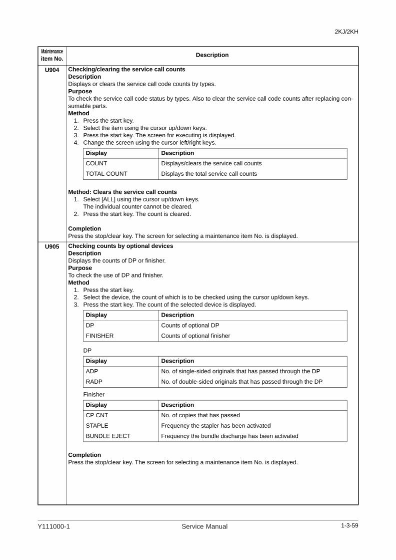
2KJ/2KH
U904 Checking/clearing the service call countsDescriptionDisplays or clears the service call code counts by types.PurposeTo check the service call code status by types. Also to clear the service call code counts after replacing con-sumable parts.Method
1. Press the start key.2. Select the item using the cursor up/down keys.3. Press the start key. The screen for executing is displayed.4. Change the screen using the cursor left/right keys.
Method: Clears the service call counts1. Select [ALL] using the cursor up/down keys.
The individual counter cannot be cleared.2. Press the start key. The count is cleared.
CompletionPress the stop/clear key. The screen for selecting a maintenance item No. is displayed.
U905 Checking counts by optional devicesDescriptionDisplays the counts of DP or finisher.PurposeTo check the use of DP and finisher.Method
1. Press the start key.2. Select the device, the count of which is to be checked using the cursor up/down keys.3. Press the start key. The count of the selected device is displayed.
DP
Finisher
CompletionPress the stop/clear key. The screen for selecting a maintenance item No. is displayed.
Maintenanceitem No. Description
Display DescriptionCOUNT Displays/clears the service call counts
TOTAL COUNT Displays the total service call counts
Display Description
DP Counts of optional DP
FINISHER Counts of optional finisher
Display DescriptionADP No. of single-sided originals that has passed through the DP
RADP No. of double-sided originals that has passed through the DP
Display Description
CP CNT No. of copies that has passed
STAPLE Frequency the stapler has been activated
BUNDLE EJECT Frequency the bundle discharge has been activated
1-3-59Y111000-1 Service Manual
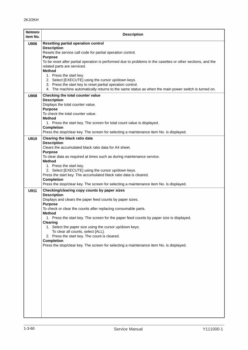
2KJ/2KH
U906 Resetting partial operation controlDescriptionResets the service call code for partial operation control.PurposeTo be reset after partial operation is performed due to problems in the casettes or other sections, and the related parts are serviced.Method
1. Press the start key.2. Select [EXECUTE] using the cursor up/down keys.3. Press the start key to reset partial operation control.4. The machine automatically returns to the same status as when the main power switch is turned on.
U908 Checking the total counter valueDescriptionDisplays the total counter value.PurposeTo check the total counter value.Method
1. Press the start key. The screen for total count value is displayed.CompletionPress the stop/clear key. The screen for selecting a maintenance item No. is displayed.
U910 Clearing the black ratio dataDescriptionClears the accumulated black ratio data for A4 sheet.PurposeTo clear data as required at times such as during maintenance service.Method
1. Press the start key.2. Select [EXECUTE] using the cursor up/down keys.
Press the start key. The accumulated black ratio data is cleared.CompletionPress the stop/clear key. The screen for selecting a maintenance item No. is displayed.
U911 Checking/clearing copy counts by paper sizesDescriptionDisplays and clears the paper feed counts by paper sizes.PurposeTo check or clear the counts after replacing consumable parts.Method
1. Press the start key. The screen for the paper feed counts by paper size is displayed.Clearing
1. Select the paper size using the cursor up/down keys.To clear all counts, select [ALL].
2. Press the start key. The count is cleared.CompletionPress the stop/clear key. The screen for selecting a maintenance item No. is displayed.
Maintenanceitem No. Description
1-3-60 Service Manual Y111000-1

2KJ/2KH
U917 Setting backup data reading/writingDescriptionStores backup data from the fax control PWB (when an optional fax kit is installed) into CompactFlash or reads the data from CompactFlash.PurposeTo store and write data when replacing the PWB.Setting
1. Press the power key on the operation panel, and after verifying the power indicator has gone off, switch off the main power switch. And then unplug the power cable from the wall outlet.
2. Remove the screw and remove the slot cover.3. Insert Compact Flash in a notch hole of the machine.4. Connect the power plug. While pressing the copier key, turn the main power switch on.
Press and hold on the Copier key until the message "Please wait." disappears.5. Enter the maintenance item.6. Press the start key.7. Select the item using the cursor up/down keys.
8. Press the start key. Reading or writing is executed, and the screen displays the result.If the operation was successful:EXECUTE 0100CHECK SUM ****CODE 0000If the operation failed:EXECUTE 0100CHECK SUM ****CODE XXXXWhere XXX is the error code indicating the reason for the failure.See Error Codes for Operation U917 and U926 below.
9. Press the power key on the operation panel, and after verifying the power indicator has gone off, switch off the main power switch. And then unplug the power cable from the wall outlet.
10. Remove the Compact Flash from the machine.11. Refit the slot cover.
Error Codes for Operation U917 and U926
Maintenanceitem No. Description
Display Description
SRAM→CF:BKUP Writing the backup data of fax control PWB
CF→SRAM:BKUP Reading the backup data of fax control PWB
SRAM→CF:DIAL Writing the backup data of fax dial information
CF→SRAM:DIAL Reading the backup data of fax dial information
Code Description
0102 Detects call for service on fax control PWB.
0103 Detects call for service on engine PWB.
0104 Communication error.
0105 Detects call for service on main PWB.
01FF CF error.
0202 No CF card.
0203 No data in CF card.
0204 CF data is incompatible.
0205 Bad CF data (Checksum error)
0206 CF read error.
0207 CF write error.
0212 Fax control PWB flash memory error.
1-3-61Y111000-1 Service Manual

2KJ/2KH
U920 Checking the copy countsDescriptionChecks the copy counts.PurposeTo check the copy counts.Method
1. Press the start key. The current counts of copy counter, printer counter and fax counter are displayed.CompletionPress the stop/clear key. The screen for selecting a maintenance item No. is displayed.
U925 Checking/clearing the system error countsDescriptionDisplays and clears the count value of system error.PurposeTo check the system error status by types. Also to clear the service call code counts after replacing consum-able parts.Method
1. Press the start key. The count for system error detection by type is displayed.2. Change the screen using the cursor left/right keys.
Clearing1. Select [ALL] using the cursor up/down keys.
The individual counter cannot be cleared.2. Press the start key. The count is cleared.
CompletionPress the stop/clear key. The screen for selecting a maintenance No. item is displayed.
Maintenanceitem No. Description
1-3-62 Service Manual Y111000-1

2KJ/2KH
U926 Rewriting FAX programDescriptionDownloads the fax program and fax fonts when installing an optional fax kit.PurposeTo run when upgrading the fax program and fax fonts.Setting
1. Press the power key on the operation panel, and after verifying the power indicator has gone off, switch off the main power switch. And then unplug the power cable from the wall outlet.
2. Remove the screw and remove the slot cover.3. Insert Compact Flash in a notch hole of the machine.4. Connect the power plug. While pressing the copier key, turn the main power switch on.
Press and hold on the Copier key until the message "Please wait." disappears.5. Enter the maintenance item.6. Press the start key.
Downloading of the fax program starts and the result shown below is displayed.
If the operation was successful:EXECUTE 0100CHECK SUM ****CODE 0000
If the operation failed:EXECUTE 0100CHECK SUM ****CODE XXXXWhere XXX is the error code indicating the reason for the failure.
7. Then, downloading of the fax fonts starts and the result shown below is displayed.
If the operation was successful:EXECUTE 0100CHECK SUM ****CODE 0000
If the operation failed:EXECUTE 0100CHECK SUM ****CODE XXXXWhere XXX is the error code indicating the reason for the failure.See Error Codes for Operation U917 and U926 on P.1-3-61.
8. Press the power key on the operation panel, and after verifying the power indicator has gone off, switch off the main power switch. And then unplug the power cable from the wall outlet.
9. Remove the Compact Flash from the machine.10. Refit the slot cover.
Maintenanceitem No. Description
1-3-63Y111000-1 Service Manual

2KJ/2KH
U927 Clearing the all copy counts and machine life counts (one time only)DescriptionResets all of the counts back to 0.PurposeTo start the counters with value 0 when installing the machine.SupplementThe total account counter and the machine life counter can be cleared only once if all count values are 1000 or less.Method
1. Press the start key.2. Select [EXECUTE] using the cursor up/down keys.3. Press the start key. All copy counts and machine life counts are cleared.
[CANNOT EXECUTE] is displayed if the count cannot be cleared.CompletionPress the stop/clear key. The screen for selecting a maintenance item No. is displayed.
U928 Checking machine life countsDescriptionDisplays the machine life counts.PurposeTo check the machine life counts.Method
1. Press the start key. The current machine life counts is displayed.CompletionPress the stop/clear key. The screen for selecting a maintenance item No. is displayed.
U931 Setting the automatic toner installDescriptionSets automatic toner installation on or off when power is turned on.PurposeChanged to off when deactivating automatic toner installation.Setting
1. Press the start key.2. Select ON or OFF using the cursor up/down keys.
Initial setting: OFF3. Press the start key. The setting is set.
CompletionPress the stop/clear key. The screen for selecting a maintenance item No. is displayed.
Maintenanceitem No. Description
Display Description
ON Automatic toner install function ON
OFF Automatic toner install function OFF
1-3-64 Service Manual Y111000-1

2KJ/2KH
U941 Setting the default magnification ratio of the default cassetteDescriptionSets the default magnification ratio when paper selection of copy default setting is set to the default cassette. PurposeTo be set according to user request.Setting
1. Press the strat key.2. Select the magnification using the cursor up/down keys.
Initial setting: 100% magnification3. Press the start key. The setting is set.
CompletionPress the stop/clear key. The screen for selecting a maintenance item No. is displayed.
U942 Setting of deflection for feeding from DPDescriptionAdjusts the deflection generated when the DP is used.PurposeUse this mode if an original non-feed jam, oblique feed or wrinkling of original occurs when the DP is used.Setting
1. Press the start key.2. Select the item to be adjusted using the cursor up/down keys.
3. Press the interrupt key.4. Place an original on the DP and press the start key to make a test copy.5. Change the setting value using the cursor left/right keys.
The greater the value, the larger the deflection; the smaller the value, the smaller the deflection.If an original non-feed jam or oblique feed occurs, increase the setting value. If wrinkling of original occurs, decrease the value.
6. Press the start key. The value is set.CompletionPress the stop/clear key. The screen for selecting a maintenance item No. is displayed.
U969 Checking of toner area codeDescriptionDisplays the toner area code.PurposeTo check the toner area code.Method
1. Press the start key. The toner area code is displayed.CompletionPress the stop/clear key. The screen for selecting a maintenance item No. is displayed.
Maintenanceitem No. Description
Display Description100 100% magnification
Aut Auto magnification selection
Display Description Setting range Initial setting
FEED MOT Deflection in the original feed motor -10 to 20 0
REV MOT Deflection in the original switchback motor -10 to 20 0
1-3-65Y111000-1 Service Manual

2KJ/2KH
U990 Checking/clearing the time for the exposure lamp to lightDescriptionDisplays, clears or changes the accumulated time for the exposure lamp to light.PurposeTo check duration of use of the exposure lamp. Also to clear the accumulated time for the lamp after replace-ment.Method
1. Press the start key. The accumulated time of illumination for the exposure lamp is displayed in minutes.
Setting1. Select [TIME] using the cursor up/down keys.2. Change the accumulated time using the numeric key.3. Press the start key. The accumulated time is set.
Clearing1. Select [CLEAR] using the cursor up/down keys.2. Press the start key. The accumulated time is cleared.
CompletionPress the stop/clear key. The screen for selecting a maintenance item No. is displayed.
U991 Checking the scanner countDescriptionDisplays the scanner operation count.PurposeTo check the status of use of the scanner.Method
1. Press the start key. The screen for the scanner operation count is desplayed.
CompletionPress the stop/clear key. The screen for selecting a maintenance item No. is displayed.
Maintenanceitem No. Description
Display Description
COPY Scanner operation count for copying
FAX Scanner operation count for fax
NWS Network scanner operation count
1-3-66 Service Manual Y111000-1

2KJ/2KH
U993 Outputting a VTC-PG patternDescriptionSelects and outputs a VTC-PG pattern created in the machine.PurposeWhen performing respective image printing adjustments, used to check the machine status apart from that of the scanner with a non-scanned output VTC-PG pattern.Method
1. Press the start key.2. Select the VTC-PG pattern to be output using the cursor up/down keys.
3. Press the interrupt key.4. Press the start key. A VTC-PG pattern is output.
CompletionPress the stop/clear key. The screen for selecting a maintenance item No. is displayed.
Maintenanceitem No. Description
Display PG pattern to be output Purpose
PG1 Leading edge registration adjust-mentCenter line adjustmentMargin adjustment
PG2 Lateral squareness adjustmentMagnification adjustment
PG3 Driving unevenness of drum
1-3-67Y111000-1 Service Manual

2KJ/2KH
1-3-2 Management modeIn addition to a maintenance function for service, the machine is equipped with a management function which can be oper-ated by users (mainly by the administrator). In this management mode, settings such as default settings can be changed.
(1) Using the management mode
Select [Job Accounting] and
then press the enter key.
Enter the
management code.
Press the system menu/counter key.
Execute job accounting items
(page 1-3-69).
Select [Copy default] and then
press the enter key.
Enter the
management code.
Make copy default settings
(page 1-3-70).Press the reset key.
Select [Machine default] and
then press the enter key.
Enter the
management code.
Make machine default settings
(page 1-3-71).
Select [Counter check] and
then press the enter key.
Check the counter
(page 1-3-73).
Select [MP Tray Setting] and
then press the enter key.
Make MP tray settings
(page 1-3-73).
Select [Print report] and then
press the enter key.
Output the report (page 1-3-73).
Start
End
Select [Language] and then
press the enter key.
Select the [End] and
press the enter key.
Press the reset key.
Press the reset key.
Press the reset key.
Set the language (page 1-3-73).
1-3-68 Service Manual Y111000-1

2KJ/2KH
(2) Setting the job accounting
Registering a new accountRegisters ID-codes and the limit of use for each account. 1. Select [Edit Job Accounting] and then press the
enter key. 2. Select [New registration] and then press the enter
key. 3. Enter the ID-code (up to 8 digits) using the numeric
keys. 4. Press the enter key. 5. Set the lmit of use.
Deleting an account1. Select [Edit Job Accounting] and then press the
enter key. 2. Select [Delete] and then press the enter key. 3. Select the ID-code to delete and then press the
enter key. 4. Select [Yes] or [No] and then press the enter key.
Changing limit of use1. Select [Edit Job Accounting] using the cursor up/
down keys and then press the enter key. 2. Select [Change limit in use] using the cursor up/
down keys and then press the enter key. 3. Select the ID-code to change and then press the
enter key. 4. Change the limit of use.
All account managementYou can browse the total output count, output the job accounting report, and clear the counter for all accounts. 1. Select [Job Accounting Total] and then press the
enter key. 2. Select [Print report] and then press the enter key.
The management report is printed out. 3. Select [Counter clear] and then press the enter key.4. Select [Yes] or [No] and then press the enter key.
Individual account managementChecks the output count and/or clears the counter for individual accounts. 1. Select [Each Job Accouning TL] and then press the
enter key. The output counts of individual accounts are displayed.
2. Select the ID-code to clear and then press the enter key.
3. Select [Yes] or [No] and then press the enter key.
Enabling job accounting1. Select [Job Accounting On/Off] and then press the
enter key. 2. Select [On] or [Off] and then press the enter key.
Copier job accounting1. Select [Job Accounting Def. Set.] and then press
the enter key. 2. Select [Copy Job Account.] and then press the
enter key. 3. Select [On] or [Off] and then press the enter key.
Printer job accounting1. Select [Job Accounting Def. Set.] and then press
the enter key. 2. Select [Prnt Job Account.] and then press the enter
key. 3. Select [On] or [Off] and then press the enter key.
Scanner job accountingNote: This setting is only available when the optional network scanner board is installed in the machine. 1. Select [Job Accounting Def. Set.] and then press
the enter key. 2. Select [Scanner Job Accnt] and then press the
enter key. 3. Select [On] or [Off] and then press the enter key.
Fax job accountingNote: This setting is only available when the optional fax kit is installed in the machine. 1. Select [Job Accounting Def. Set.] and then press
the enter key. 2. Select [Fax Job Accountng] and then press the
enter key. 3. Select [On] or [Off] and then press the enter key.
Operation against excess over limitDetermines whether to stop output by prohibiting immediately use of the machine, to stop the operation from the next job or to display a warning message onle, when the limit of count that has been set with the func-tion of the limit of use is exceeded. 1. Select [Job Accounting Def. Set.] and then press
the enter key. 2. Select [Excess limit Set.] and then press the enter
key. 3. Select [Stop job immediately], [Stop after job done]
or [Only warning]and then press the enter key.
1-3-69Y111000-1 Service Manual

2KJ/2KH
(3) Copy default
Density modeSelects the exposure mode at power-on. 1. Select [Exposure Mode] and then press the enter
key. 2. Select [Manual] or [Auto] and then press the enter
key.
Original image qualitySelects the original image quality at power-on.
1. Select [Orig Image] and then press the enter key. 2. Select [Text+Photo], [Photo] or [Text] and then
press the enter key.
Eco print mode ON/OFFDetermines whether or not the eco print mode will be the default setting in the initial mode. 1. Select [EcoPrint] and then press the enter key.2. Select [On] or [Off] and then press the enter key.
Background color adjustmentAdjust the ground color of the copied paper. 1. Select [Background adjst] and then press the enter
key. 2. Adjust the exposure and then press the enter key.
Setting range: 1 to 5
Paper selectionSets whether the copier will automatically select the same size of copy paper as the original once an origi-nal is set, or whether the designated default drawer will be automatically selected. 1. Select [Paper Select] and then press the enter key.2. Select [Auto] or [Default cassette] and then press
the enter key.
Paper type (Auto paper selection mode)Selects the types of paper that will be available for selection under the APS (Auto Paper Selection) mode. 1. Select [Paper type(Auto)] and then press the enter
key. 2. Select [On] or [Off] and then press the enter key. 3. If selected [On], select the desired paper type and
then press the enter key.
Default cassetteSets one cassette that will be selected automatically regardless of the size of paper loaded in that cassette. 1. Select [Default cassette] and then press the entrer
key. 2. Select the drawer that will be used with priority.
Settings: Cassette 1/Cassette 2/Cassette 3/ Cas-sette 4
Default magnificationSets whether or not the appropriate magnification ratio to be calculated automatically when selecting the size of copy paper. 1. Select [Default magnif.] and then press the enter
key.2. Select [100%] or [Auto %] and then press the enter
key.
Auto density adjustmentAdjusts the overall density level for the auto density mode. 1. Select [Adj.Auto dens] and then press the enter
key. 2. Adjust the density and then press the enter key.
Setting range: 1 to 7
Auto density adjustment (OCR)Adjusts the overall density level for scanning with OCR (Optical Character Recognition) software when using the optional scanner functions of this machine. 1. Select [Auto dens(OCR)] and then press the enter
key.2. Adjust the density and then press the enter key.
Setting range: 1 to 7
Density adjustment for Text + Photo originalsAdjusts the median density value when the text+photo mode is selected for the image quality. 1. Select [Txt+Photo Dens] and then press the enter
key. 2. Adjust the density and then press the enter key.
Setting range: 1 to 7
Density adjustment for Text originalsAdjusts the median density value when the text mode is selected for the image quality. 1. Select [Txt Ori Density] and then press the enter
key.2. Adjust the density and then press the enter key.
Setting range: 1 to 7
Density adjustment for Photo originalsAdjusts the median density value when the photo mode is selected for the image quality. 1. Select [Photo Ori Dnsity] and then press the enter
key. 2. Adjust the density and then press the enter key.
Setting range: 1 to 7
Collate copyingDetermines whether or not the Sort mode will be the default setting in the initial mode. 1. Select [Collate] and then press the enter key. 2. Select [On] or [Off] and then press the enter key.
1-3-70 Service Manual Y111000-1

2KJ/2KH
Offset copyingDetermines whether or not the offset copy will be the default setting in the initial mode. 1. Select [Offset] and then press the enter key. 2. Select [On] or [Off] and then press the enter key.
Auto rotation copyDetermines whether or not the Auto Rotation mode will be the default setting in the initial mode. 1. Select [Auto Rotation] and then press the enter key. 2. Select [On] or [Off] and then press the enter key.
Margin width default valueDetermines the default value of the location and width of the margins in the margin mode. 1. Select [Margin Width] and then press the enter key.2. Sets the margin widths and then press the enter
key.Setting range: 1/8" to 3/4" in 1/8" increments (inch specifications) 1 to 18 mm in 1mm increments (metric specifications)
Border erase width default valueDetermines the default value for the width of the border to be erased in the two border erase modes. 1. Select [BorderEraseWidth] and then press the
enter key.2. Sets the widths and then press the enter key.
Setting range: 1/8" to 3/4" in 1/8" increments (inch specifications) 1 to 18 mm in 1mm increments (metric specifications)
Limit of number of copiesSets the limit for the number of copies (or copy sets) that can be made at a time. 1. Select [Copy Limit] and then press the enter key. 2. Sets the copy limit and then press the enter key.
Setting range: 1 to 999
Black streaking reduction processingReduces black lines that may be caused when the DP is used. 1. Select [Corr. Black line] and then press the enter
key. 2. Select [None], [Weak] or [Strong] and then press
the enter key.
(4) Machine default
Auto cassette switchingTurns automatic cassette switching ON or OFF. 1. Select [Auto Cassette SW] and then press the enter
key.2. Select [On/All types of paper], [On/Only same
paper type] or [Off] and then press the enter key.
Paper size (cassettes 1 to 4)Sets the size of paper that is loaded in cassettes 1 through 4. 1. Select one of the [Paper Size (1st) to (4th)] and
then press the enter key. 2. Select [Auto Detection Metric], [Auto Detection
Inch] or a paper size and then press the enter key.
Paper type (cassettes 1 to 4)Sets the type of paper that is loaded in cassettes 1 through 4. 1. Select one of the [Paper Type (1st) to (4th)] and
then press the enter key. 2. Select the paper type and then press the enter key.
MP tray confirmation display1. Select one of the [Check MP Tray] and then press
the enter key. 2. Select [On] or [Off] and then press the enter key.
Paper weight for paper typeSets the paper weight for each paper type. 1. Select [P. type (Weight)] and then press the enter
key. 2. Select paper type and then press the enter key. 3. Select paper weight and then press the enter key.
Duplex print for paper typeSets whether or not each custom type of paper (cus-tom 1 to custom 8) will be available for use in duplex printing. 1. Select [P. type (Duplex)] and then press the enter
key. 2. Select one of the [Custom 1 to 8] and then press
the enter key.3. Select [On] or [Off] and then press the enter key.
Custom paper typeSets whether or not to match the orientation in one-sided printing and two-sided printing. 1. Select [Special P. type] and then press the enter
key. 2. Select [Match Print Direction] or [Fast Mode] and
then press the enter key.
1-3-71Y111000-1 Service Manual

2KJ/2KH
Original orientationSets the default original orientation. 1. Select [Orig. direction] and then press the enter
key.2. Select [Top Edge Top] or [Top Edge Left] and then
press the enter key.
Auto sleep timeSets the time that elapses before the auto sleep func-tion. 1. Select [Sleep mode time] and then press the enter
key. 2. Sets sleep mode type and then press the enter key.
Setting range:1 to 240 min (Inch specifications)1 to 120 mim (metric specifications)
Auto low power timeSets the time that elapses before the low power mode is automatically activated. 1. Select [Low power time] and then press the enter
key. 2. Sets low power time and then press the enter key.
Setting range:1 to 240 mm (Inch specifications)1 to 120 mm (metric specifications)
Copy output destinationSets the paper output location with priority for copying. This setting is only available when the optional finisher or job separator are installed in the machine. 1. Select [Copy Otput Destn] and then press the enter
key. 2. Select output location and then press the enter key.
Fax output destinationSets where incoming faxes will be ejected. This setting is only available when the optional fax kit, finisher or job separator are installed in the machine. 1. Select [Fax Otput Destn] and then press the enter
key. 2. Select output location and then press the enter key.
Default operation modeSets whether the display that appears after power is turned on to the machine will be the one for the copy operation mode or for the fax operation mode. This set-ting is only available when the optional fax kit is installed. 1. Select [Main mode] and then press the enter key. 2. Select [Copy mode] or [Fax mode] and then press
the enter key.
Key soundSets whether or not the operation panel will emit a beep sound each time a key is pressed. 1. Select [Key sound On/Off] and then press the enter
key. 2. Select [On] or [Off] and then press the enter key.
Date and timeSets the current date and time. 1. Select [Date/Time] and then press the enter key. 2. Sets the current date and time. 3. Select [End] and then press the enter key.
Display contrast adjustmentAdjust the display contrast. 1. Select [Display Contrast] and then press the enter
key. 2. Adjust the contrast and then press the enter key.
Setting range: 1 to 7
Administrator management code changeChanges the administrator management code. 1. Select [Admin. Code] and then press the enter key. 2. Enter a new 4-digit administrator management
code using the numeric keys.
Auto sleepSets whether or not to have the auto sleep function. This setting is displayed only on the inch specification model. 1. Select [Auto Sleep] and then press the enter key. 2. Select [On] or [Off] and then press the enter key.
Auto clearSets whether or not to have the auto clear function. 1. Select [Auto Clear] and then press the enter key. 2. Select [On] or [Off] and then press the enter key.
Auto clear timeSets the time that elapses from completion of copying to activation of the auto cler function. 1. Select [Auto Clear Time] and then press the enter
key. 2. Sets the time and then press the enter key. Setting
range: 10 to 270 s
Silent modeSets whether or not to use the silent mode which short-ens the length of time that the laser data writing motor continues to spin after each copy job is finished. 1. Select [Silent Mode] and then press the enter key. 2. Select [On] or [Off] and then press the enter key.
1-3-72 Service Manual Y111000-1
2KJ/2KH
Machine administrator management code changeChanges the four-digit management code for the secu-rity administrator of the other machine.1. Select [MachineAdminCode] and then press the
enter key. 2. Enter a new security administrator management
code using the numeric keys.
(5) MP Tray setting
Paper size and typeSets the paper size and paper type for the MP tray set-tings.1. Select paper size.
If the paper size is unknown or no particular paper size setting is required, select [Universal Size].
2. When setting a size, turn on the size input and use the left/right cursor key to select the paper size.Setting range:(Inch specifications)Width: 3 7/8" to 11 5/8"Length: 5 7/8" to 17"(Metric specifications)Width: 98 to 297 mmLength: 148 to 432 mm
3. Press the enter key. 4. Select paper type and then press the enter key.
Selecting other standard sizesSets a special standard size. 1. Select [Other Regular Size] and then press the
enter key. 2. Select paper size and then press the enter key. 3. Select paper type and then press the enter key.
(6) Checking the total counter and printing out the counter report
Checks the total count of copies, etc., and prints out the information as a counter report. 1. Select [Counter check] and then press the enter
key. 2. Select [Output count] or [Scan count] and then
press the enter key. 3. Select [End] and then press the enter key. 4. Select [Print counter report] and then press the
enter key to print out a counter report.
(7) Report output
Prints out one of the status report. 1. Select [Print Report] and then press the enter key. 2. Select the report to print out and then press the
enter key.[Copy report][Machine report][Coverage report]The selected status report will be printed out.
(8) Language setting
Switches the language to be displayed on the opera-tion panel.1. Select [Language] and then press the enter key. 2. Select the language to use and then press the enter
key.Available languages:Inch specificationsJapanese, English, French and SpanishMetric specificationsEnglish, German, French, Spanish and Italian
1-3-73Y111000-1 Service Manual

2KJ/2KH
This page is intentionally left blank.
1-3-74 Service Manual Y111000-1

2KJ/2KH
1-4 Troubleshooting
1-4-1 Paper misfeed detection
(1) Paper misfeed indication
When a paper misfeed occurs, the machine immediately stops copying and displays the jam location on the operationpanel.Paper misfeed counts sorted by the detection condition can be checked in maintenance item U903.To remove paper jammed in the machine, open the front cover, left cover or pull the cassette out.To remove original jammed in the optional DP, open the document processor top cover.To remove the jammed paper in optional document finisher, detach the finisher from the machine.Paper misfeed detection can be reset by opening and closing the respective covers to turn safety switch off and on.
Figure 1-4-1
1
5
6
7
8
2
3
4
1
2
3
4
(1) Misfeed in cassette(2) Misfeed in first paper feeder(3) Misfeed in second paper feeder(4) Misfeed in third paper feeder(5) Misfeed in MP tray(6) Misfeed in paper conveying section(7) Misfeed in eject section
(job separator or built-in finisher)(8) Misfeed in document processor
1-4-1Y111000-1 Service Manual
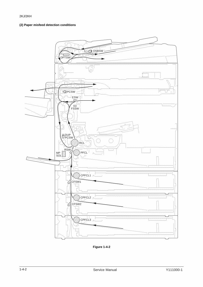
2KJ/2KH
(2) Paper misfeed detection conditions
Figure 1-4-2
ESW
PCSW
OSBSW
DPTSW
FSSW
CFSW1
CFSW2
DUPPCSW
RCL
RSWMPSOL
PFCL
CPFCL1
CPFCL2
CPFCL3
1-4-2 Service Manual Y111000-1

2KJ/2KH
Section Description Conditions Specified time
System 00No paper feed
The power is turned on when a sensor in the conveying system is on.
-
The document processor is opened while originals fed from the document processor are scanned.
-
04Cover open
Cover is open during copying. -
05Secondary paper feed does not start
Secondary paper feed does not start within specified time of arrival of paper at the registration section.
30 s
Paper feedsection
10No paper feed from MP tray
The registration switch (RSW) does not turn on within the specified time of paper MP solenoid (MPSOL) turning on and cannot be detected at the same timing even after retry.
1570 ms
11No paper feed from cassette
The registration switch (RSW) does not turn on within the specified time of paper paper feed clutch 1 (PFCL1) turn-ing on and cannot be detected at the same timing even after retry.
1327 ms
12No paper feed from first paper feeder
The registration switch (RSW) does not turn on within the specified time of cassette paper paper feed clutch 1 (CPFCL1) turning on and cannot be detected at the same timing even after retry.
2290 ms
13No paper feed from second paper feeder
Cassette feed switch 1 (CFSW1) does not turn on within the specified time of cassette paper paper feed clutch 2 (CPFCL2) turning on and cannot be detected at the same timing even after retry.
1953 ms
14No paper feed from third paper feeder
Cassette feed switch 2 (CFSW2) does not turn on within the specified time of cassette paper paper feed clutch 3 (CPFCL3) turning on and cannot be detected at the same timing even after retry.
1953 ms
15Misfeed in vertical paper conveying sec-tion 1
The registration switch (RSW) does not turn on within specified time of cassette feed switch 1 (CFSW1) turning on.
2243 ms
Cassette feed switch 1 (CFSW1) does not turn off within specified time of cassette feed switch 2 (CFSW2) turning on.
1916 ms
Cassette feed switch 1 (CFSW1) does not turn off within specified time of cassette feed switch 2 (CFSW2) turning off.
1916 ms
Left cover is opened in prior to the cassette feed switch 1 (CFSW1) is turned off.
-
16Misfeed in vertical paper conveying sec-tion 2
Cassette feed switch 1 (CFSW1) does not turn on within specified time of cassette feed switch 2 (CFSW2) turning on.
1916 ms
Left cover is opened in prior to the cassette feed switch 2 (CFSW2) is turned off.
-
20Multiple sheets in MP tray
The registration switch (RSW) does not turn off within specified time of its turning on.
5907 ms
The registration switch (RSW) does not turn off within the specified time of paper MP solenoid (MPSOL) turning on.
1570 ms
1-4-3Y111000-1 Service Manual

2KJ/2KH
Paper feedsection
21Multiple sheets in cas-sette
The registration switch (RSW) does not turn off within specified time of its turning on.
5907 ms
The registration switch (RSW) does not turn off within the specified time of paper feed clutch (PFCL) turning on.
1327 ms
22Multiple sheets in first paper feeder
The registration switch (RSW) does not turn off within specified time of its turning on.
5907 ms
The registration switch (RSW) does not turn off within the specified time of cassette paper feed clutch 1 (CPFCL1) turning on.
2290 ms
23Multiple sheets in sec-ond paper feeder
Cassette feed switch 1 (CFSW1) does not turn off within specified time of its turning on.
5907 ms
Cassette feed switch 1 (CFSW1) does not turn off within the specified time of cassette paper feed clutch 2 (CPFCL2) turning on.
1953 ms
24Multiple sheets in third paper feeder
Cassette feed switch 2 (CFSW2) does not turn off within specified time of its turning on.
5907 ms
Cassette feed switch 2 (CFSW2) does not turn off within the specified time of cassette paper feed clutch 3 (CPFCL3) turning on.
1953 ms
Paperconveying section
30Misfeed in registration/transfer section
A message, which is not the one indicating start of sec-ondary paper feed, is received when the machine waits for start of secondary paper feed.
-
The registration switch (RSW) does not turn off within specified time of the cassette feed switch 1 (CFSW1) turning on (paper feed from second paper feeder).
2523 ms
The registration switch (RSW) does not turn off within specified time of the cassette feed switch 1 (CFSW1) turning on (paper feed from third paper feeder).
2243 ms
The registration switch (RSW) does not turn off within specified time of the cassette feed switch 1 (CFSW1) turning off.
2243 ms
The registration switch (RSW) does not turn off within specified time of the duplex paper conveying switch (DUPPCSW) turning on.
1589 ms
Fusersection
40Misfeed in fuser section (MP tray)
The eject switch (ESW) does not turn on within specified time of the registration clutch (RCL) turning on.
2766 ms
The feedshift switch (FSSW) does not turn on within specified time of the registration clutch (RCL) turning on.
2766 ms
41Misfeed in fuser section (cassette)
The eject switch (ESW) does not turn on within specified time of the registration clutch (RCL) turning on.
2766 ms
The feedshift switch (FSSW) does not turn on within specified time of the registration clutch (RCL) turning on.
2766 ms
42Misfeed in fuser section (first paper feeder)
The eject switch (ESW) does not turn on within specified time of the registration clutch (RCL) turning on.
2766 ms
43Misfeed in fuser section (second paper feeder)
The eject switch (ESW) does not turn on within specified time of the registration clutch (RCL) turning on.
2766 ms
Section Description Conditions Specified time
1-4-4 Service Manual Y111000-1

2KJ/2KH
Fusersection
44Misfeed in fuser section (third paper feeder)
The eject switch (ESW) does not turn on within specified time of the registration clutch (RCL) turning on.
2766 ms
45Misfeed in fuser section (duplex section)
The eject switch (ESW) does not turn on within specified time of the registration clutch (RCL) turning on.
2766 ms
Ejectsection
50Misfeed in eject section
The eject switch (ESW) does not turn off within specified time of the registration switch (RSW) turning off.
2766 ms
The eject switch (ESW) does not turn off within specified time of the registration clutch (RCL) turning on.
2766 ms
51Misfeed in job separa-tor eject section
The job eject switch (JBESW) does not turn off within specified time of the feedshift switch (FSSW) turning on.
2056 ms
The job eject switch (JBESW) does not turn off within specified time of the feedshift switch (FSSW) turning off.
2056 ms
Feedshift section
52Misfeed in feedshift section (MP tray)
The job eject switch (JBESW) does not turn on within specified time of the feedshift switch (FSSW) turning on.
2056 ms
The feedshift switch (FSSW) does not turn on within specified time of paper switchback operation.
1364 ms
The feedshift switch (FSSW) does not turn off within specified time of the registration clutch (RCL) turning on.
2766 ms
The feedshift switch (FSSW) does not turn off within specified time of the its turning on.
5907 ms
53Misfeed in feedshift section (cassette)
The job eject switch (JBESW) does not turn on within specified time of the feedshift switch (FSSW) turning on.
2056 ms
The feedshift switch (FSSW) does not turn on within specified time of paper switchback operation.
1364 ms
The feedshift switch (FSSW) does not turn off within specified time of the registration clutch (RCL) turning on.
2766 ms
The feedshift switch (FSSW) does not turn off within specified time of the its turning on.
5907 ms
54Misfeed in feedshift section (first paper feeder)
The job eject switch (JBESW) does not turn on within specified time of the feedshift switch (FSSW) turning on.
2056 ms
The feedshift switch (FSSW) does not turn on within specified time of paper switchback operation.
1364 ms
The feedshift switch (FSSW) does not turn off within specified time of the registration clutch (RCL) turning on.
2766 ms
The feedshift switch (FSSW) does not turn off within specified time of the its turning on.
5907 ms
55Misfeed in feedshift section (second paper feeder)
The job eject switch (JBESW) does not turn on within specified time of the feedshift switch (FSSW) turning on.
2056 ms
The feedshift switch (FSSW) does not turn on within specified time of paper switchback operation.
1364 ms
The feedshift switch (FSSW) does not turn off within specified time of the registration clutch (RCL) turning on.
2766 ms
The feedshift switch (FSSW) does not turn off within specified time of the its turning on.
5907 ms
Section Description Conditions Specified time
1-4-5Y111000-1 Service Manual

2KJ/2KH
Feedshift section
56Misfeed in feedshift section (third paper feeder)
The job eject switch (JBESW) does not turn on within specified time of the feedshift switch (FSSW) turning on.
2056 ms
The feedshift switch (FSSW) does not turn on within specified time of paper switchback operation.
1364 ms
The feedshift switch (FSSW) does not turn off within specified time of the registration clutch (RCL) turning on.
2766 ms
The feedshift switch (FSSW) does not turn off within specified time of the its turning on.
5907 ms
57Misfeed in feedshift section (duplex section)
The job eject switch (JBESW) does not turn on within specified time of the feedshift switch (FSSW) turning on.
2056 ms
The feedshift switch (FSSW) does not turn on within specified time of paper switchback operation.
1364 ms
The feedshift switch (FSSW) does not turn off within specified time of the registration clutch (RCL) turning on.
2766 ms
The feedshift switch (FSSW) does not turn off within specified time of the its turning on.
5907 ms
Duplexsection
60Misfeed in duplex paper conveying sec-tion
The duplex paper conveying switch (DUPPCSW) does not turn off within specified time of the feedshift switch (FSSW) turning on.
3037 ms
The duplex paper conveying switch (DUPPCSW) does not turn on within specified time of the feedshift switch (FSSW) turning on.
3037 ms
The duplex paper conveying switch (DUPPCSW) does not turn off within specified time of the feedshift switch (FSSW) turning off.
3037 ms
61Misfeed in duplex eject section
The registration switch (RSW) does not turn on within specified time of the duplex paper conveying switch (DUPPCSW) turning on.
1589 ms
The registration switch (RSW) does not turn off within specified time of the duplex paper conveying switch (DUPPCSW) turning off.
1589 ms
Documentprocessor
70No original feed
During primary feed of the second original in the simplex or duplex mode, even if retry operation is performed five times, primary original feed is not performed.
-
71An original jam in the original conveying sec-tion 1
During the secondary original feed in the simplex mode, DP timing switch (DPTSW) does not turn off within speci-fied time of the original conveying motor (OCM) turning on.
9900 pulses
72An original size error jam
DP timing switch (DPTSW) turns off within the specified time of period of the original conveying motor (OCM) turning on in the simplex or duplex mode.
1145 pulses
73An original jam in the original conveying sec-tion 2
During original conveying in the duplex mode, DP timing switch (DPTSW) does not turn off within specified time of the original conveying motor (OCM) turning on.
9900 pulses
74An original jam in the original conveying sec-tion 3
During secondary original feed in the duplex mode, DP timing switch (DPTSW) does not turn on within specified time of the original switchback motor (OSBM) turning on.
2300 pulses
Section Description Conditions Specified time
1-4-6 Service Manual Y111000-1
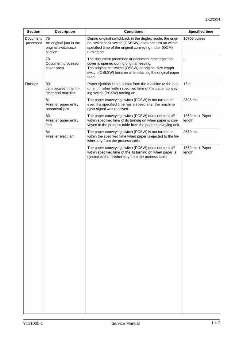
2KJ/2KH
Document processor
75An original jam in the original switchback section
During original switchback in the duplex mode, the origi-nal switchback switch (OSBSW) does not turn on within specified time of the original conveying motor (OCM) turning on.
10700 pulses
78Document processor cover open
The document processor or document processor top cover is opened during original feeding.The original set switch (OSSW) or original size length switch (OSLSW) turns on when starting the original paper feed.
-
Finisher 80Jam between the fin-isher and machine
Paper ejection is not output from the machine to the doc-ument finisher within specified time of the paper convey-ing switch (PCSW) turning on.
15 s
81Finisher paper entry nonarrival jam
The paper conveying switch (PCSW) is not turned on even if a specified time has elapsed after the machine eject signal was received.
2598 ms
83Finisher paper entry jam
The paper conveying switch (PCSW) does not turn off within specified time of its turning on when paper is con-veyed to the process table from the paper conveying unit.
1869 ms + Paper length
84Finisher eject jam
The paper conveying switch (PCSW) is not turned on within the specified time when paper is ejected to the fin-isher tray from the process table.
2570 ms
The paper conveying switch (PCSW) does not turn off within specified time of the its turning on when paper is ejected to the finisher tray from the process table.
1869 ms + Paper length
Section Description Conditions Specified time
1-4-7Y111000-1 Service Manual

2KJ/2KH
(3) Paper misfeeds
Problem Causes/check procedures Corrective measures
(1)A paper jam in the paper feed, convey-ing or eject section is indicated as soon as the main power switch is turned on.
A piece of paper torn from copy paper is caught around registration switch, eject switch or feedshift switch.
Check visually and remove it, if any.
Defective switch. Run maintenance item U031 and turn switch on and off manually. Replace the switch if indication of the corresponding switch is not light.Registration switch, eject switch, feedshift switch
(2)A paper jam in the paper feed section is indicated during copying (no paper feed from MP tray).Jam code 10
Paper is extremely curled. Change the paper.
Check if the MP paper feed pulley is deformed.
Check visually and replace any deformed pulley.
Broken registration switch actuator.
Check visually and replace switch.
Defective registration switch.
Run maintenance item U031 and turn registration switch on and off manually. Replace the switch if indication of the corresponding switch is not light.
Check if the MP solenoid malfunctions.
Run maintenance item U032 and select the MP solenoid to be turned on and off. Check the status and remedy if necessary.
Electrical problem with the MP solenoid.
Check (see page 1-4-32).
(3)A paper jam in the paper feed section is indicated during copying (no paper feed from cassette).Jam code 11
Paper is extremely curled. Change the paper.
Check if the paper feed pul-ley, separation pulley or for-warding pulley is deformed.
Check visually and replace any deformed pulley.
Broken registration switch actuator.
Check visually and replace switch.
Defective registration switch.
Run maintenance item U031 and turn registration switch on and off manually. Replace the switch if indication of the corresponding switch is not light.
Check if the paper feed clutch malfunctions.
Run maintenance item U032 and select the paper feed clutch to be turned on and off. Check the status and remedy if necessary.
Electrical problem with the paper feed clutch.
Check (see page 1-4-32).
(4)A paper jam in the paper feed section is indicated during copying (no paper feed from first paper feeder).Jam code 12
Paper is extremely curled. Change the paper.
Check if the paper feed pul-ley, separation pulley or for-warding pulley is deformed.
Check visually and replace any deformed pulley.
Broken registration switch actuator.
Check visually and replace switch.
Defective registration switch.
Run maintenance item U031 and turn registration switch on and off manually. Replace the switch if indication of the corresponding switch is not light.
Check if the cassette paper feed clutch 1 malfunctions.
Run maintenance item U032 and select the cassette paper feed clutch 1 to be turned on and off. Check the status and remedy if necessary.
Electrical problem with the cassette paper feed clutch 1.
Check (see page 1-4-32).
1-4-8 Service Manual Y111000-1

2KJ/2KH
(5)A paper jam in the paper feed section is indicated during copying (no paper feed from second paper feeder).Jam code 13
Paper is extremely curled. Change the paper.
Check if the paper feed pul-ley, separation pulley or for-warding pulley is deformed.
Check visually and replace any deformed pulley.
Broken cassette feed switch 1 actuator.
Check visually and replace switch.
Defective cassette feed switch 1.
Run maintenance item U031 and turn cassette feed switch 1 on and off manually. Replace the switch if indication of the corre-sponding switch is not light.
Check if the cassette paper feed clutch 2 malfunctions.
Run maintenance item U032 and select the cassette paper feed clutch 2 to be turned on and off. Check the status and remedy if necessary.
Electrical problem with the cassette paper feed clutch 2.
Check (see service manual of paper feeder).
(6)A paper jam in the paper feed section is indicated during copying (no paper feed from third paper feeder).Jam code 14
Paper is extremely curled. Change the paper.
Check if the paper feed pul-ley, separation pulley or for-warding pulley is deformed.
Check visually and replace any deformed pulley.
Broken cassette feed switch 2 actuator.
Check visually and replace switch.
Defective cassette feed switch 2.
Run maintenance item U031 and turn cassette feed switch 2 on and off manually. Replace the switch if indication of the corre-sponding switch is not light.
Check if the cassette paper feed clutch 3 malfunctions.
Run maintenance item U032 and select the cassette paper feed clutch 3 to be turned on and off. Check the status and remedy if necessary.
Electrical problem with the cassette paper feed clutch 3.
Check (see service manual of paper feeder).
(7)A paper jam in the paper feed section is indicated during copying (misfeed in vertical paper con-veying section 1).Jam code 15
Broken registration switch, cassette feed switch 1 or 2 actuator.
Check visually and replace switch.
Defective switch. Run maintenance item U031 and turn switch on and off manually. Replace the switch if indication of the corresponding switch is not light.Registration switch, cassette feed switch 1, 2
Check if the paper feed clutch, cassette paper feed clutch 1, 2 or 3 malfunc-tions.
Run maintenance item U032 and select the clutch to be turned on and off. Check the status and remedy if necessary.
Electrical problem with the paper feed clutch, cassette paper feed clutch 1, 2 or 3.
Check (see service manual of paper feeder).
Defective feed pulleys or feed rollers.
Check visually and replace.
Problem Causes/check procedures Corrective measures
1-4-9Y111000-1 Service Manual

2KJ/2KH
(8)A paper jam in the paper feed section is indicated during copying (misfeed in vertical paper con-veying section 2).Jam code 16
Broken cassette feed switch 1 or 2 actuator.
Check visually and replace switch.
Defective switch. Run maintenance item U031 and turn switch on and off manually. Replace the switch if indication of the corresponding switch is not light.Cassette feed switch 1, 2
Check if the paper feed clutch, cassette paper feed clutch 1 or 2 malfunctions.
Run maintenance item U032 and select the clutch to be turned on and off. Check the status and remedy if necessary.
Electrical problem with the paper feed clutch, cassette paper feed clutch 1 or 2.
Check (see service manual of paper feeder).
Defective feed pulleys or feed rollers.
Check visually and replace.
(9)A paper jam in the paper feed section is indicated during copying (multiple sheets in MP tray).Jam code 20
Deformed guides along the paper conveying path.
Check visually and replace.
Broken registration switch actuator.
Check visually and replace switch.
Defective registration switch.
Run maintenance item U031 and turn registration switch on and off manually. Replace the switch if indication of the corresponding switch is not light.
Check if the MP solenoid malfunctions.
Run maintenance item U032 and select the MP solenoid to be turned on and off. Check the status and remedy if necessary.
Electrical problem with the MP solenoid.
Check (see page 1-4-32).
Check if the right and left registration rollers contact each other.
Check visually and replace.
(10)A paper jam in the paper feed section is indicated during copying (multiple sheets in cassette).Jam code 21
Deformed guides along the paper conveying path.
Check visually and replace.
Broken registration switch actuator.
Check visually and replace switch.
Defective registration switch.
Run maintenance item U031 and turn registration switch on and off manually. Replace the switch if indication of the corresponding switch is not light.
Check if the paper feed clutch malfunctions.
Run maintenance item U032 and select the paper feed clutch to be turned on and off. Check the status and remedy if necessary.
Electrical problem with the paper feed clutch.
Check (see page 1-4-32).
Check if the right and left registration rollers contact each other.
Check visually and replace.
Problem Causes/check procedures Corrective measures
1-4-10 Service Manual Y111000-1

2KJ/2KH
(11)A paper jam in the paper feed section is indicated during copying (multiple sheets in first paper feeder).Jam code 22
Deformed guides along the paper conveying path.
Check visually and replace.
Broken registration switch actuator.
Check visually and replace switch.
Defective registration switch.
Run maintenance item U031 and turn registration switch on and off manually. Replace the switch if indication of the corresponding switch is not light.
Check if the cassette paper feed clutch 1 malfunctions.
Run maintenance item U032 and select the cassette paper feed clutch 1 to be turned on and off. Check the status and remedy if necessary.
Electrical problem with the cassette paper feed clutch 1.
Check (see page 1-4-32).
Check if the right and left registration rollers contact each other.
Check visually and replace.
(12)A paper jam in the paper feed section is indicated during copying (multiple sheets in second paper feeder).Jam code 23
Deformed guides along the paper conveying path.
Check visually and replace.
Broken cassette feed switch 1 actuator.
Check visually and replace switch.
Defective cassette feed switch 1.
Run maintenance item U031 and turn cassette feed switch 1 on and off manually. Replace the switch if indication of the corre-sponding switch is not light.
Check if the cassette paper feed clutch 2 malfunctions.
Run maintenance item U032 and select the cassette paper feed clutch 2 to be turned on and off. Check the status and remedy if necessary.
Electrical problem with the cassette paper feed clutch 2.
Check (see page 1-4-32).
(13)A paper jam in the paper feed section is indicated during copying (multiple sheets in third paper feeder).Jam code 24
Deformed guides along the paper conveying path.
Check visually and replace.
Broken cassette feed switch 2 actuator.
Check visually and replace switch.
Defective cassette feed switch 2.
Run maintenance item U031 and turn cassette feed switch 2 on and off manually. Replace the switch if indication of the corre-sponding switch is not light.
Check if the cassette paper feed clutch 3 malfunctions.
Run maintenance item U032 and select the cassette paper feed clutch 3 to be turned on and off. Check the status and remedy if necessary.
Electrical problem with the cassette paper feed clutch 3.
Check (see page 1-4-32).
Problem Causes/check procedures Corrective measures
1-4-11Y111000-1 Service Manual

2KJ/2KH
(14)A paper jam in the paper conveying sec-tion is indicated dur-ing copying (misfeed in registration/trans-fer section).Jam code 30
Deformed guides along the paper conveying path.
Check visually and replace.
Broken registration switch, cassette feed switch 1 or duplex paper conveying switch actuator.
Check visually and replace switch.
Defective switch. Run maintenance item U031 and turn switch on and off manually. Replace the switch if indication of the corresponding switch is not light.Registration switch, cassette feed switch 1, duplex paper convey-ing switch
(15)A paper jam in the fuser section is indi-cated during copying (misfeed in fuser sec-tion). Jam codes 40, 41, 42, 43, 44 and 45
Check if the front fuser guide is deformed.
Check visually and replace.
Check if the press roller is extremely dirty or deformed.
Clean or replace if necessary.
Check if the heat roller sep-aration claws are dirty or deformed.
Clean or replace if necessary.
Check if the heat roller and its separation claws contact each other.
Check visually and replace.
Broken eject switch or feed-shift switch actuator.
Check visually and replace switch.
Defective switch. Run maintenance item U031 and turn switch on and off manually. Replace the switch if indication of the corresponding switch is not light.Eject switch, feedshift switch
Check if the registration clutch malfunctions.
Run maintenance item U032 and select the registration clutch to be turned on and off. Check the status and remedy if necessary.
Electrical problem with the registration clutch.
Check (see page 1-4-32).
(16)A paper jam in the eject section is indi-cated during copying (misfeed in eject sec-tion).Jam code 50
Broken eject switch or reg-istration switch actuator.
Check visually and replace switch.
Defective switch. Run maintenance item U031 and turn switch on and off manually. Replace the switch if indication of the corresponding switch is not light.Eject switch, registration switch
Check if the registration clutch malfunctions.
Run maintenance item U032 and select the registration clutch to be turned on and off. Check the status and remedy if necessary.
Electrical problem with the registration clutch.
Check (see page 1-4-32).
(17)A paper jam in the eject section is indi-cated during copying (misfeed in job sepa-rator eject section).Jam code 51
Broken feedshift switch or job eject switch actuator.
Check visually and replace switch.
Defective switch. Run maintenance item U031 and turn switch on and off manually. Replace the switch if indication of the corresponding switch is not light.Feedshift switch, job eject switch
Problem Causes/check procedures Corrective measures
1-4-12 Service Manual Y111000-1

2KJ/2KH
(18)A paper jam in the feedshift section is indicated during copying (misfeed in feedshift section). Jam code 52, 53, 54, 55, 56, 57
Broken feedshift switch, registration switch or job eject switch actuator.
Check visually and replace switch.
Defective switch. Run maintenance item U031 and turn switch on and off manually. Replace the switch if indication of the corresponding switch is not light.Feedshift switch, registration switch, job eject switch
Check if the eject motor malfunctions.
Run maintenance item U030 and select the eject motor to be turned on and off. Check the status and remedy if necessary.
Electrical problem with the eject motor.
Check (see page 1-4-32).
(19)A paper jam in the duplex section is indi-cated during copying (misfeed in duplex paper conveying sec-tion). Jam code 60
Broken feedshift switch or duplex paper conveying switch actuator.
Check visually and replace switch.
Defective switch. Run maintenance item U031 and turn switch on and off manually. Replace the switch if indication of the corresponding switch is not light.Feedshift switch, duplex paper conveying switch
Check if the eject motor malfunctions.
Run maintenance item U030 and select the eject motor to be turned on and off. Check the status and remedy if necessary.
Electrical problem with the eject motor.
Check (see page 1-4-32).
Check if the duplex feed clutch malfunctions.
Run maintenance item U032 and select the duplex feed clutch to be turned on and off. Check the status and remedy if necessary.
Electrical problem with the duplex feed clutch.
Check (see page 1-4-32).
(20)A paper jam in the duplex section is indi-cated during copying (misfeed in duplex eject section).Jam code 61
Broken duplex paper con-veying switch or registration switch actuator.
Check visually and replace switch.
Defective switch. Run maintenance item U031 and turn switch on and off manually. Replace the switch if indication of the corresponding switch is not light.Duplex paper conveying switch, registration switch
Check if the duplex feed clutch malfunctions.
Run maintenance item U032 and select the duplex feed clutch to be turned on and off. Check the status and remedy if necessary.
Electrical problem with the duplex feed clutch.
Check (see page 1-4-32).
(21)An original jams in DP is indicated dur-ing copying (no origi-nal feed).Jam code 70
Defective original set switch.
Run maintenance item U244 and turn the original set switch on and off manually. Replace the switch if indication of the corre-sponding switch is not light.
Check if the original feed motor malfunctions.
Run maintenance item U243 and select the original feed motor to be turned on and off. Check the status and remedy if necessary.
Check if the DP paper feed pulley or DP separation pad is deformed.
Check visually and replace.
Problem Causes/check procedures Corrective measures
1-4-13Y111000-1 Service Manual

2KJ/2KH
(22)An original jams in DP is indicated dur-ing copying (an origi-nal jam in the original conveying section 1).Jam code 71
Defective DP timing switch. Run maintenance item U244 and turn the DP timing switch on and off manually. Replace the switch if indication of the corresponding switch is not light.
Check if the original con-veying motor malfunctions.
Run maintenance item U243 and select the original conveying motor to be turned on and off. Check the status and remedy if nec-essary.
(23)An original jams in DP is indicated dur-ing copying (an origi-nal size error jam).Jam code 72
Defective DP timing switch. Run maintenance item U244 and turn the DP timing switch on and off manually. Replace the switch if indication of the corresponding switch is not light.
Check if the original con-veying motor malfunctions.
Run maintenance item U243 and select the original conveying motor to be turned on and off. Check the status and remedy if nec-essary.
(24)An original jams in DP is indicated dur-ing copying (an origi-nal jam in the original conveying section 2). Jam code 73
Defective DP timing switch. Run maintenance item U244 and turn the DP timing switch on and off manually. Replace the switch if indication of the corresponding switch is not light.
Check if the original con-veying motor malfunctions.
Run maintenance item U243 and select the original conveying motor to be turned on and off. Check the status and remedy if nec-essary.
(25)An original jams in DP is indicated dur-ing copying (an origi-nal jam in the original conveying section 3). Jam code 74
Defective DP timing switch. Run maintenance item U244 and turn the DP timing switch on and off manually. Replace the switch if indication of the corresponding switch is not light.
Check if the original con-veying motor malfunctions.
Run maintenance item U243 and select the original conveying motor to be turned on and off. Check the status and remedy if nec-essary.
(26)An original jams in DP is indicated dur-ing copying (an origi-nal jam in the original switchback section). Jam code 75
Defective DP timing switch. Run maintenance item U244 and turn the DP timing switch on and off manually. Replace the switch if indication of the corresponding switch is not light.
Check if the original switch-back motor malfunctions.
Run maintenance item U243 and select the original switchback motor to be turned on and off. Check the status and remedy if nec-essary.
(27)A paper jam in fin-isher is indicated dur-ing copying (jam between the finisher and machine).Jam code 80
Extremely curled paper. Change the paper.
Defective paper conveying switch.
With 5 V DC present at YC2-23 on the finisher control PWB, check if YC2-21 on the finisher control PWB remains low or high when the paper conveying switch is turned on and off. If it does, replace the paper conveying switch.
(28)A paper jam in fin-isher is indicated dur-ing copying (finisher paper entry nonar-rival jam).Jam code 81
Extremely curled paper. Change the paper.
Defective paper conveying switch.
With 5 V DC present at YC2-23 on the finisher control PWB, check if YC2-21 on the finisher control PWB remains low or high when the paper conveying switch is turned on and off. If it does, replace the paper conveying switch.
(29)A paper jam in fin-isher is indicated dur-ing copying (finisher paper entry jam).Jam code 83
Defective paper conveying switch.
With 5 V DC present at YC2-23 on the finisher control PWB, check if YC2-21 on the finisher control PWB remains low or high when the paper conveying switch is turned on and off. If it does, replace the paper conveying switch.
Check if the feedshift roller or feedshift pulley is deformed.
Check visually and replace.
Problem Causes/check procedures Corrective measures
1-4-14 Service Manual Y111000-1

2KJ/2KH
(30)A paper jam in fin-isher is indicated dur-ing copying (finisher eject jam).Jam code 84
Defective paper conveying switch.
With 5 V DC present at YC2-23 on the finisher control PWB, check if YC2-21 on the finisher control PWB remains low or high when the paper conveying switch is turned on and off. If it does, replace the paper conveying switch.
Check if the feedshift roller or feedshift pulley is deformed.
Check visually and replace.
Check if the eject roller or eject pulley is deformed.
Check visually and replace.
Problem Causes/check procedures Corrective measures
1-4-15Y111000-1 Service Manual
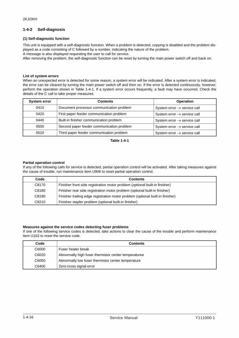
2KJ/2KH
1-4-2 Self-diagnosis
(1) Self-diagnostic function
This unit is equipped with a self-diagnostic function. When a problem is detected, copying is disabled and the problem dis-played as a code consisting of C followed by a number, indicating the nature of the problem. A message is also displayed requesting the user to call for service.After removing the problem, the self-diagnostic function can be reset by turning the main power switch off and back on.
List of system errorsWhen an unexpected error is detected for some reason, a system error will be indicated. After a system error is indicated,the error can be cleared by turning the main power switch off and then on. If the error is detected continuously, however,perform the operation shown in Table 1-4-1. If a system error occurs frequently, a fault may have occurred. Check thedetails of the C call to take proper measures.
Table 1-4-1
Partial operation controlIf any of the following calls for service is detected, partial operation control will be activated. After taking measures againstthe cause of trouble, run maintenance item U906 to reset partial operation control.
Measures against the service codes detecting fuser problemsIf one of the following service codes is detected, take actions to clear the cause of the trouble and perform maintenanceitem U163 to reset the service code.
System error Contents Operation0410 Document processor communication problem System error → service call0420 First paper feeder communication problem System error → service call0440 Built-in finisher communication problem System error → service call 0500 Second paper feeder communication problem System error → service call 0510 Third paper feeder communication problem System error → service call
Code ContentsC8170 Finisher front side registration motor problem (optional built-in finisher)C8180 Finisher rear side registration motor problem (optional built-in finisher)C8190 Finisher trailing edge registration motor problem (optional built-in finisher)C8210 Finisher stapler problem (optional built-in finisher)
Code ContentsC6000 Fuser heater breakC6020 Abnormally high fuser thermistor center temperatureeC6050 Abnormally low fuser thermistor center temperatureC6400 Zero-cross signal error
1-4-16 Service Manual Y111000-1

2KJ/2KH
(2) Self diagnostic codes
Code ContentsRemarks
Causes Check procedures/corrective measures
C0030 Fax control PWB system problemProcessing with the fax software was disabled due to a hardware or software problem.
Defective fax con-trol PWB.
Replace the fax control PWB and verify the operation.
C0070 Abnormal detection of fax control PWB incompatibilityFax software is not compatible with main software
Fax software or main software is something of the other machine.
Check the version of the fax software and the main software, upgrade the version to the compatible software.
C0100 Backup memory (EEPROM) deviceproblem (Main PWB)Reading from or writing to EEPROM cannot be performed.
Defective main PWB.
Replace the main PWB and check for cor-rect operation.
C0110 Backup memory data problem (Main PWB)Data in the specified area of the backup memory does not match the specified values.
Data damage of EEPROM.
Contact the Service Administrative Division.
C0130 Backup memory device problem (Main EEPROM)Reading from or writing to EEPROM cannot be performed.
Defective main PWB.
Replace the main PWB and check for cor-rect operation.
Device damage of EEPROM.
Contact the Service Administrative Division.
C0140 Backup memory data problem (Main EEPROM)Reading data from EEPROM is abnor-mal.
Data damage of EEPROM.
Contact the Service Administrative Division.
C0150 Backup memory device problem (Engine EEPROM)Reading from or writing to EEPROM cannot be performed.
Defective engine PWB.
Replace the engine PWB and check for cor-rect operation.
Device damage of EEPROM.
Contact the Service Administrative Division.
C0160 Backup memory data problem (Engine EEPROM)Reading data from EEPROM is abnor-mal.
Data damage of EEPROM.
Contact the Service Administrative Division.
C0170 Copy counts problemWhen the power is turned on, the total count and the scan count are abnormal both on the main PWB and the engine PWB.
Data damage of EEPROM.
Contact the Service Administrative Division.
Defective PWB. Replace the main PWB or engine PWB and check for correct operation.
C0180 Machine number mismatchMachine number of main PWB and engine PWB does not match.
Data damage of EEPROM.
Contact the Service Administrative Division.
1-4-17Y111000-1 Service Manual
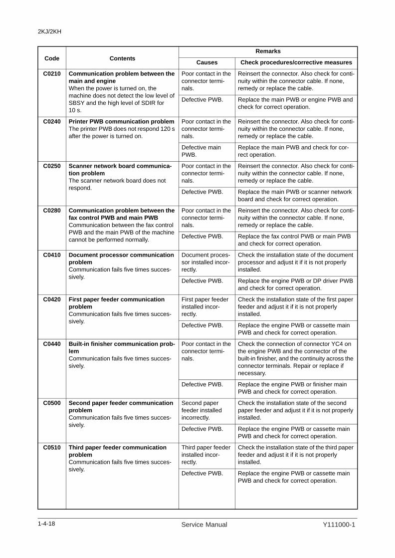
2KJ/2KH
C0210 Communication problem between the main and engineWhen the power is turned on, the machine does not detect the low level of SBSY and the high level of SDIR for 10 s.
Poor contact in the connector termi-nals.
Reinsert the connector. Also check for conti-nuity within the connector cable. If none, remedy or replace the cable.
Defective PWB. Replace the main PWB or engine PWB and check for correct operation.
C0240 Printer PWB communication problemThe printer PWB does not respond 120 s after the power is turned on.
Poor contact in the connector termi-nals.
Reinsert the connector. Also check for conti-nuity within the connector cable. If none, remedy or replace the cable.
Defective main PWB.
Replace the main PWB and check for cor-rect operation.
C0250 Scanner network board communica-tion problemThe scanner network board does not respond.
Poor contact in the connector termi-nals.
Reinsert the connector. Also check for conti-nuity within the connector cable. If none, remedy or replace the cable.
Defective PWB. Replace the main PWB or scanner network board and check for correct operation.
C0280 Communication problem between the fax control PWB and main PWBCommunication between the fax control PWB and the main PWB of the machine cannot be performed normally.
Poor contact in the connector termi-nals.
Reinsert the connector. Also check for conti-nuity within the connector cable. If none, remedy or replace the cable.
Defective PWB. Replace the fax control PWB or main PWB and check for correct operation.
C0410 Document processor communication problemCommunication fails five times succes-sively.
Document proces-sor installed incor-rectly.
Check the installation state of the document processor and adjust it if it is not properly installed.
Defective PWB. Replace the engine PWB or DP driver PWB and check for correct operation.
C0420 First paper feeder communication problemCommunication fails five times succes-sively.
First paper feeder installed incor-rectly.
Check the installation state of the first paper feeder and adjust it if it is not properly installed.
Defective PWB. Replace the engine PWB or cassette main PWB and check for correct operation.
C0440 Built-in finisher communication prob-lemCommunication fails five times succes-sively.
Poor contact in the connector termi-nals.
Check the connection of connector YC4 on the engine PWB and the connector of the built-in finisher, and the continuity across the connector terminals. Repair or replace if necessary.
Defective PWB. Replace the engine PWB or finisher main PWB and check for correct operation.
C0500 Second paper feeder communication problemCommunication fails five times succes-sively.
Second paper feeder installed incorrectly.
Check the installation state of the second paper feeder and adjust it if it is not properly installed.
Defective PWB. Replace the engine PWB or cassette main PWB and check for correct operation.
C0510 Third paper feeder communication problemCommunication fails five times succes-sively.
Third paper feeder installed incor-rectly.
Check the installation state of the third paper feeder and adjust it if it is not properly installed.
Defective PWB. Replace the engine PWB or cassette main PWB and check for correct operation.
Code ContentsRemarks
Causes Check procedures/corrective measures
1-4-18 Service Manual Y111000-1
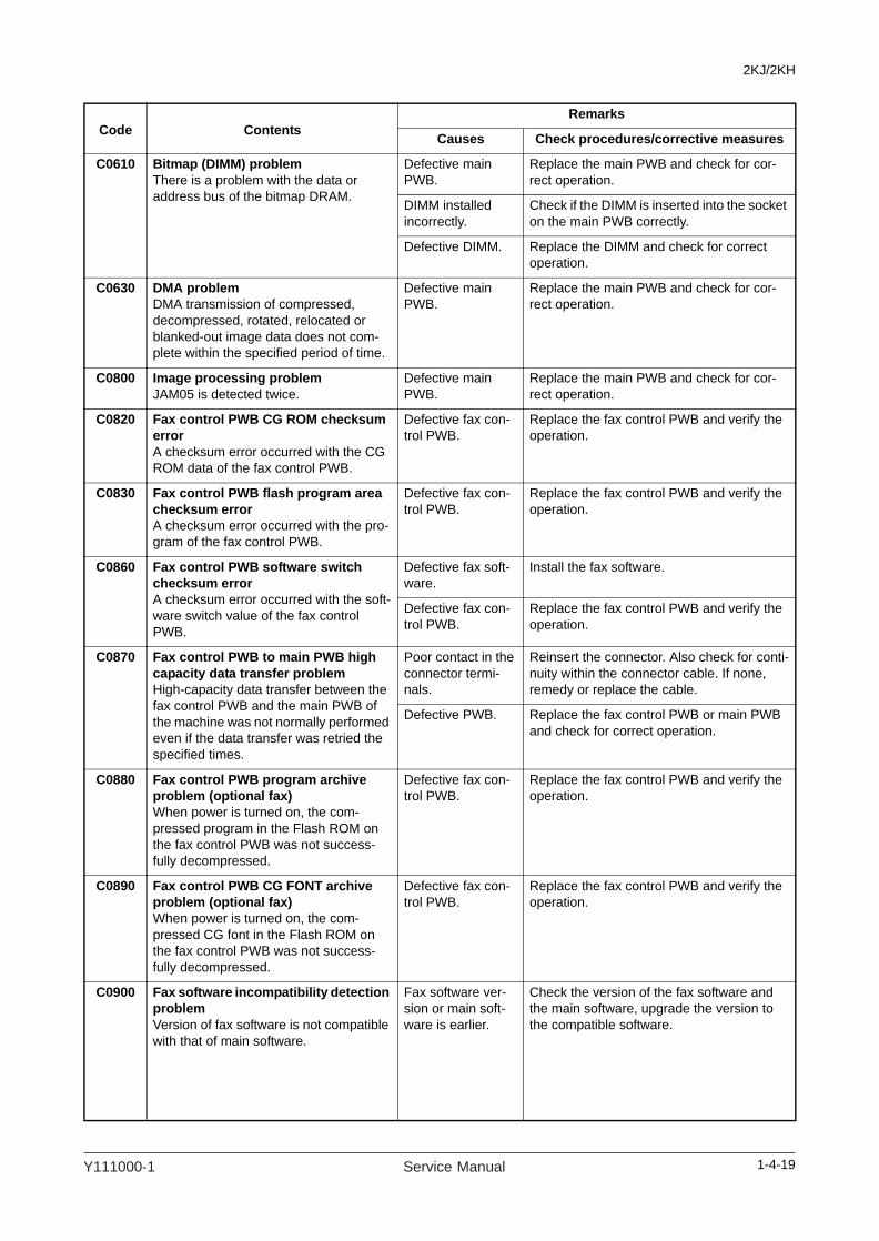
2KJ/2KH
C0610 Bitmap (DIMM) problemThere is a problem with the data or address bus of the bitmap DRAM.
Defective main PWB.
Replace the main PWB and check for cor-rect operation.
DIMM installed incorrectly.
Check if the DIMM is inserted into the socket on the main PWB correctly.
Defective DIMM. Replace the DIMM and check for correct operation.
C0630 DMA problemDMA transmission of compressed, decompressed, rotated, relocated or blanked-out image data does not com-plete within the specified period of time.
Defective main PWB.
Replace the main PWB and check for cor-rect operation.
C0800 Image processing problemJAM05 is detected twice.
Defective main PWB.
Replace the main PWB and check for cor-rect operation.
C0820 Fax control PWB CG ROM checksum errorA checksum error occurred with the CG ROM data of the fax control PWB.
Defective fax con-trol PWB.
Replace the fax control PWB and verify the operation.
C0830 Fax control PWB flash program area checksum errorA checksum error occurred with the pro-gram of the fax control PWB.
Defective fax con-trol PWB.
Replace the fax control PWB and verify the operation.
C0860 Fax control PWB software switch checksum errorA checksum error occurred with the soft-ware switch value of the fax control PWB.
Defective fax soft-ware.
Install the fax software.
Defective fax con-trol PWB.
Replace the fax control PWB and verify the operation.
C0870 Fax control PWB to main PWB high capacity data transfer problemHigh-capacity data transfer between the fax control PWB and the main PWB of the machine was not normally performed even if the data transfer was retried the specified times.
Poor contact in the connector termi-nals.
Reinsert the connector. Also check for conti-nuity within the connector cable. If none, remedy or replace the cable.
Defective PWB. Replace the fax control PWB or main PWB and check for correct operation.
C0880 Fax control PWB program archive problem (optional fax)When power is turned on, the com-pressed program in the Flash ROM on the fax control PWB was not success-fully decompressed.
Defective fax con-trol PWB.
Replace the fax control PWB and verify the operation.
C0890 Fax control PWB CG FONT archive problem (optional fax)When power is turned on, the com-pressed CG font in the Flash ROM on the fax control PWB was not success-fully decompressed.
Defective fax con-trol PWB.
Replace the fax control PWB and verify the operation.
C0900 Fax software incompatibility detection problemVersion of fax software is not compatible with that of main software.
Fax software ver-sion or main soft-ware is earlier.
Check the version of the fax software and the main software, upgrade the version to the compatible software.
Code ContentsRemarks
Causes Check procedures/corrective measures
1-4-19Y111000-1 Service Manual
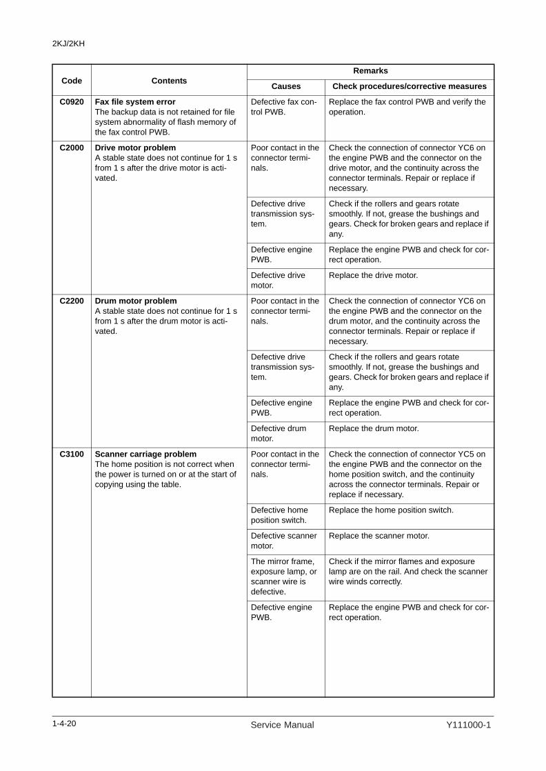
2KJ/2KH
C0920 Fax file system errorThe backup data is not retained for file system abnormality of flash memory of the fax control PWB.
Defective fax con-trol PWB.
Replace the fax control PWB and verify the operation.
C2000 Drive motor problemA stable state does not continue for 1 s from 1 s after the drive motor is acti-vated.
Poor contact in the connector termi-nals.
Check the connection of connector YC6 on the engine PWB and the connector on the drive motor, and the continuity across the connector terminals. Repair or replace if necessary.
Defective drive transmission sys-tem.
Check if the rollers and gears rotate smoothly. If not, grease the bushings and gears. Check for broken gears and replace if any.
Defective engine PWB.
Replace the engine PWB and check for cor-rect operation.
Defective drive motor.
Replace the drive motor.
C2200 Drum motor problemA stable state does not continue for 1 s from 1 s after the drum motor is acti-vated.
Poor contact in the connector termi-nals.
Check the connection of connector YC6 on the engine PWB and the connector on the drum motor, and the continuity across the connector terminals. Repair or replace if necessary.
Defective drive transmission sys-tem.
Check if the rollers and gears rotate smoothly. If not, grease the bushings and gears. Check for broken gears and replace if any.
Defective engine PWB.
Replace the engine PWB and check for cor-rect operation.
Defective drum motor.
Replace the drum motor.
C3100 Scanner carriage problemThe home position is not correct when the power is turned on or at the start of copying using the table.
Poor contact in the connector termi-nals.
Check the connection of connector YC5 on the engine PWB and the connector on the home position switch, and the continuity across the connector terminals. Repair or replace if necessary.
Defective home position switch.
Replace the home position switch.
Defective scanner motor.
Replace the scanner motor.
The mirror frame, exposure lamp, or scanner wire is defective.
Check if the mirror flames and exposure lamp are on the rail. And check the scanner wire winds correctly.
Defective engine PWB.
Replace the engine PWB and check for cor-rect operation.
Code ContentsRemarks
Causes Check procedures/corrective measures
1-4-20 Service Manual Y111000-1

2KJ/2KH
C3200 Exposure lamp problemNon-lighting of the exposure lamp is detected at the beginning of copying.
Poor contact in the connector termi-nals.
Check the connection of connector YC16 on the engine PWB and the connector on the inverter PWB, and the continuity across the connector terminals. Repair or replace if necessary.
Defective exposure lamp.
Replace the exposure lamp.
Incorrect shading position.
Adjust the position of the contact glass (shading plate). If the problem still occurs, replace the home position switch.
Defective PWB. Replace the engine PWB or inverter PWB and check for correct operation.
C3300 AGC problemAfter AGC, correct input is not obtained at CCD.
Poor contact in the connector termi-nals.
Check the connection of connector YC5 on the main PWB and the connector on the CCD PWB, and the continuity across the connector terminals. Repair or replace if necessary.
Defective exposure lamp.
Replace the exposure lamp.
Defective PWB. Replace the main PWB or CCD PWB and check for correct operation.
C4000 Polygon motor synchronization prob-lemThe polygon motor does not reach the stable speed within 20 s of the START signal turning on.
Poor contact in the connector termi-nals.
Check the connection of connector YC3 on the engine PWB and laser scanner unit, and the continuity across the connector termi-nals. Repair or replace if necessary.
Defective polygon motor.
Replace the laser scanner unit.
Defective engine PWB.
Replace the engine PWB and check for cor-rect operation.
C4010 Polygon motor steady-state problemStable OFF is detected for 5 s continu-ously after polygon motor stability.
Poor contact in the connector termi-nals.
Check the connection of connector YC3 on the engine PWB and laser scanner unit, and the continuity across the connector termi-nals. Repair or replace if necessary.
Defective polygon motor.
Replace the laser scanner unit.
Defective engine PWB.
Replace the engine PWB and check for cor-rect operation.
C4200 BD steady-state problemASIC detects a BD error for 600 ms after the polygon motor rotation has been sta-bilized.
Poor contact in the connector termi-nals.
Check the connection of connector YC3 on the engine PWB and laser scanner unit, and the continuity across the connector termi-nals. Repair or replace if necessary.
Defective laser scanner unit.
Replace the laser scanner unit.
Defective engine PWB.
Replace the engine PWB and check for cor-rect operation.
Code ContentsRemarks
Causes Check procedures/corrective measures
1-4-21Y111000-1 Service Manual

2KJ/2KH
C6000 Fuser heater breakThe temperature does not reach 70 °C/158°F in 15 s before secondary stabiliza-tion.Temperature rise of 1°C/1.8°F does not occur in 5 s before secondary stabiliza-tion (except during printing).
Poor contact in the fuser thermistor connector termi-nals.
Reinsert the connector. Also check for conti-nuity within the connector cable. If none, remedy or replace the cable.
Fuser thermistor installed incor-rectly.
Check and reinstall if necessary.
Fuser thermostat triggered.
Check for continuity. If none, replace the fuser thermostat.
Fuser heater installed incor-rectly.
Check and reinstall if necessary.
Broken fuser heater wire.
Check for continuity. If none, replace the fuser heater.
C6020 Abnormally high fuser thermistor temperatureFuser thermistor is detected 230°C/446°F or more for 40 ms.
Shorted thermistor. Measure the resistance. If it is 0 Ω, replace the thermistor.
Broken heater con-trol circuit on the power source PWB.
Replace the power source PWB and check for correct operation.
C6050 Abnormally low fuser thermistor tem-peratureFuser thermistor remains below 90°C/194°F for 1 s.
Poor contact in the fuser thermistor connector termi-nals.
Reinsert the connector. Also check for conti-nuity within the connector cable. If none, remedy or replace the cable.
Broken fuser ther-mistor wire.
Measure the resistance. If it is ∞ Ω, replace the fixing thermistor.
Fuser thermistor installed incor-rectly.
Check and reinstall if necessary.
Fuser thermostat triggered.
Check for continuity. If none, replace the fuser thermostat.
Fuser heater installed incor-rectly.
Check and reinstall if necessary.
Broken fuser heater wire.
Check for continuity. If none, replace the fuser heater.
C6400 Zero-cross signal errorInterrupt of the zero-cross signal does not occur more than 1 s.
Poor contact in the connector termi-nals.
Reinsert the connector. Also check for conti-nuity within the connector cable. If none, remedy or replace the cable.
Defective power source PWB.
Check if the zero-crossing signal is output from YC2-2 on the power source PWB. If not, replace the power source PWB.
Defective engine PWB.
Replace the engine PWB if C6400 is detected while YC2-2 on the power source PWB outputs the zero-crossing signal.
Code ContentsRemarks
Causes Check procedures/corrective measures
1-4-22 Service Manual Y111000-1
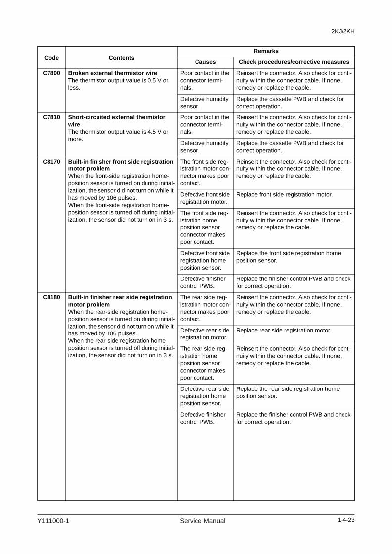
2KJ/2KH
C7800 Broken external thermistor wireThe thermistor output value is 0.5 V or less.
Poor contact in the connector termi-nals.
Reinsert the connector. Also check for conti-nuity within the connector cable. If none, remedy or replace the cable.
Defective humidity sensor.
Replace the cassette PWB and check for correct operation.
C7810 Short-circuited external thermistor wireThe thermistor output value is 4.5 V or more.
Poor contact in the connector termi-nals.
Reinsert the connector. Also check for conti-nuity within the connector cable. If none, remedy or replace the cable.
Defective humidity sensor.
Replace the cassette PWB and check for correct operation.
C8170 Built-in finisher front side registration motor problemWhen the front-side registration home-position sensor is turned on during initial-ization, the sensor did not turn on while it has moved by 106 pulses.When the front-side registration home-position sensor is turned off during initial-ization, the sensor did not turn on in 3 s.
The front side reg-istration motor con-nector makes poor contact.
Reinsert the connector. Also check for conti-nuity within the connector cable. If none, remedy or replace the cable.
Defective front side registration motor.
Replace front side registration motor.
The front side reg-istration home position sensor connector makes poor contact.
Reinsert the connector. Also check for conti-nuity within the connector cable. If none, remedy or replace the cable.
Defective front side registration home position sensor.
Replace the front side registration home position sensor.
Defective finisher control PWB.
Replace the finisher control PWB and check for correct operation.
C8180 Built-in finisher rear side registration motor problemWhen the rear-side registration home-position sensor is turned on during initial-ization, the sensor did not turn on while it has moved by 106 pulses.When the rear-side registration home-position sensor is turned off during initial-ization, the sensor did not turn on in 3 s.
The rear side reg-istration motor con-nector makes poor contact.
Reinsert the connector. Also check for conti-nuity within the connector cable. If none, remedy or replace the cable.
Defective rear side registration motor.
Replace rear side registration motor.
The rear side reg-istration home position sensor connector makes poor contact.
Reinsert the connector. Also check for conti-nuity within the connector cable. If none, remedy or replace the cable.
Defective rear side registration home position sensor.
Replace the rear side registration home position sensor.
Defective finisher control PWB.
Replace the finisher control PWB and check for correct operation.
Code ContentsRemarks
Causes Check procedures/corrective measures
1-4-23Y111000-1 Service Manual

2KJ/2KH
C8190 Built-in finisher trailing edge registra-tion motor problemWhen the trailing edge registration home-position sensor is turned on during initialization, the sensor did not turn on while it has moved by 106 pulses.When the trailing edge registration home-position sensor is turned off during initialization, the sensor did not turn on in 3 s.
The trailing edge registration motor connector makes poor contact.
Reinsert the connector. Also check for conti-nuity within the connector cable. If none, remedy or replace the cable.
Defective trailing edge registration motor.
Replace trailing edge registration motor.
The trailing edge registration home position sensor connector makes poor contact.
Reinsert the connector. Also check for conti-nuity within the connector cable. If none, remedy or replace the cable.
Defective trailing edge registration home position sen-sor.
Replace the trailing edge registration home position sensor.
Defective finisher control PWB.
Replace the finisher control PWB and check for correct operation.
C8210 Built-in finisher stapler problem The stapler home position sensor does not change state from nondetection to detection within 200 ms of the start of stapler motor counterclockwise (forward) rotation.During initialization, the stapler home position sensor does not change state from non-detection to detection within 600 ms of the start of stapler motor clockwise (reverse) rotation.
The stapler con-nector makes poor contact.
Reinsert the connector. Also check for conti-nuity within the connector cable. If none, remedy or replace the cable.
The stapler is blocked with a sta-ple.
Remove the stapler cartridge, and check the cartridge and the stapling section of the sta-pler.
The stapler is bro-ken.
Replace the front stapler and check for cor-rect operation.
Defective finisher control PWB.
Replace the finisher control PWB and check for correct operation.
Code ContentsRemarks
Causes Check procedures/corrective measures
1-4-24 Service Manual Y111000-1

2KJ/2KH
1-4-3 Image formation problems
(1)No image appears (entirely white).
(2)No image appears (entirely black).
(3)Image is too light. (4)Background isvisible.
(5)A white line appears longitudi-nally.
See page 1-4-26. See page 1-4-26. See page 1-4-27. See page 1-4-27. See page 1-4-27.
(6)A black line appears longitudi-nally.
(7)A black line appears laterally.
(8)One side of the copy image is darker than the other.
(9)Black dots appear on the image.
(10)Image is blurred.
See page 1-4-28. See page 1-4-28. See page 1-4-28. See page 1-4-28. See page 1-4-29.
(11)The leading edge of the image is consistently mis-aligned with the original.
(12)The leading edge of the image is sporadically mis-aligned with the original.
(13)Paper creases. (14)Offset occurs. (15)Image is partly missing.
See page 1-4-29. See page 1-4-29. See page 1-4-29. See page 1-4-30. See page 1-4-30.
(16)Fusing is poor. (17)Image is out of focus.
(18)Image center does not align with the original center.
See page 1-4-30. See page 1-4-30. See page 1-4-31.
1-4-25Y111000-1 Service Manual Y111000-1 Service Manual
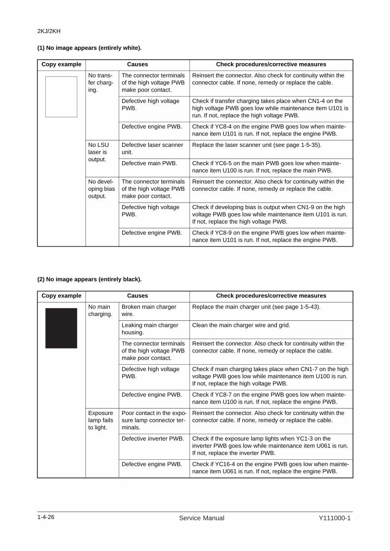
2KJ/2KH
(1) No image appears (entirely white).
(2) No image appears (entirely black).
Copy example Causes Check procedures/corrective measures
No trans-fer charg-ing.
The connector terminals of the high voltage PWB make poor contact.
Reinsert the connector. Also check for continuity within the connector cable. If none, remedy or replace the cable.
Defective high voltage PWB.
Check if transfer charging takes place when CN1-4 on the high voltage PWB goes low while maintenance item U101 is run. If not, replace the high voltage PWB.
Defective engine PWB. Check if YC8-4 on the engine PWB goes low when mainte-nance item U101 is run. If not, replace the engine PWB.
No LSU laser is output.
Defective laser scanner unit.
Replace the laser scanner unit (see page 1-5-35).
Defective main PWB. Check if YC6-5 on the main PWB goes low when mainte-nance item U100 is run. If not, replace the main PWB.
No devel-oping bias output.
The connector terminals of the high voltage PWB make poor contact.
Reinsert the connector. Also check for continuity within the connector cable. If none, remedy or replace the cable.
Defective high voltage PWB.
Check if developing bias is output when CN1-9 on the high voltage PWB goes low while maintenance item U101 is run. If not, replace the high voltage PWB.
Defective engine PWB. Check if YC8-9 on the engine PWB goes low when mainte-nance item U101 is run. If not, replace the engine PWB.
Copy example Causes Check procedures/corrective measures
No main charging.
Broken main charger wire.
Replace the main charger unit (see page 1-5-43).
Leaking main charger housing.
Clean the main charger wire and grid.
The connector terminals of the high voltage PWB make poor contact.
Reinsert the connector. Also check for continuity within the connector cable. If none, remedy or replace the cable.
Defective high voltage PWB.
Check if main charging takes place when CN1-7 on the high voltage PWB goes low while maintenance item U100 is run. If not, replace the high voltage PWB.
Defective engine PWB. Check if YC8-7 on the engine PWB goes low when mainte-nance item U100 is run. If not, replace the engine PWB.
Exposure lamp fails to light.
Poor contact in the expo-sure lamp connector ter-minals.
Reinsert the connector. Also check for continuity within the connector cable. If none, remedy or replace the cable.
Defective inverter PWB. Check if the exposure lamp lights when YC1-3 on the inverter PWB goes low while maintenance item U061 is run. If not, replace the inverter PWB.
Defective engine PWB. Check if YC16-4 on the engine PWB goes low when mainte-nance item U061 is run. If not, replace the engine PWB.
1-4-26 Service Manual Y111000-1
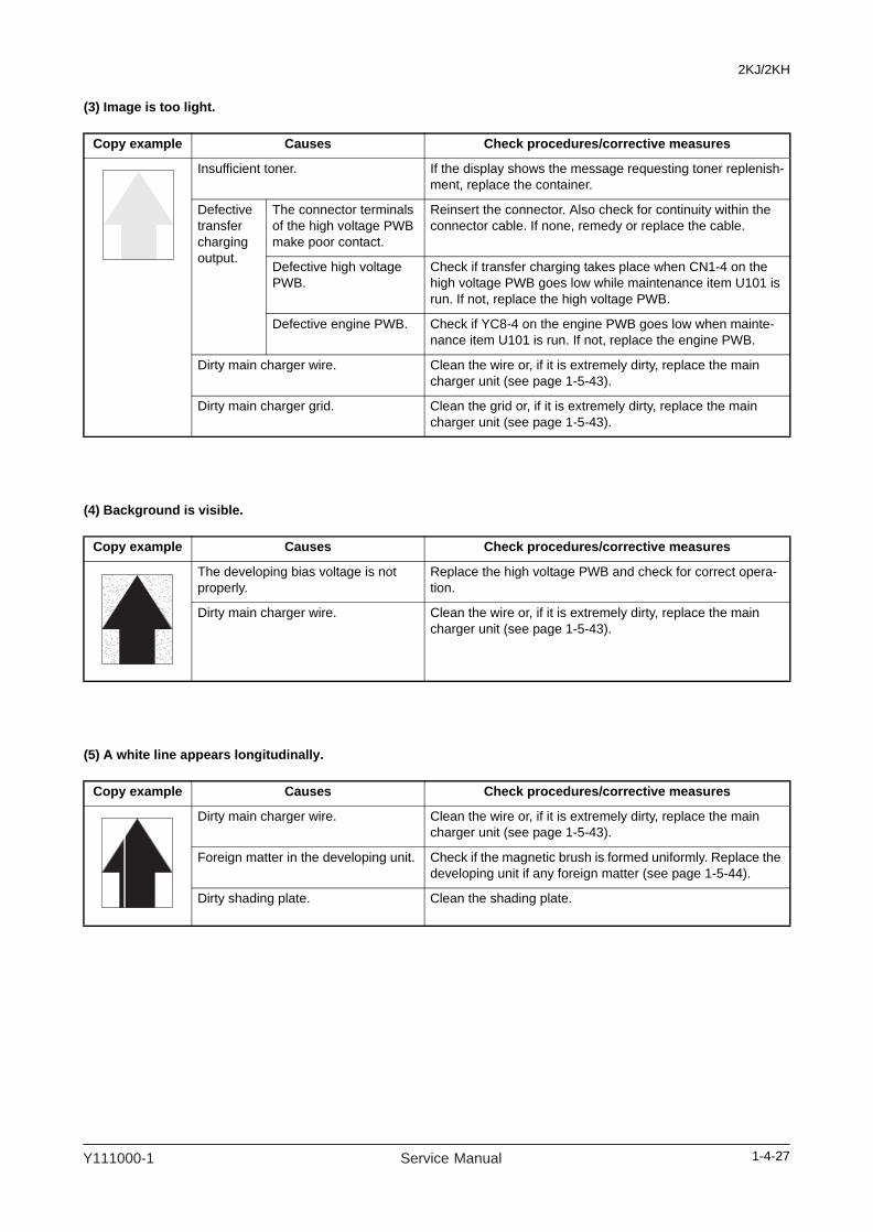
2KJ/2KH
(3) Image is too light.
(4) Background is visible.
(5) A white line appears longitudinally.
Copy example Causes Check procedures/corrective measures
Insufficient toner. If the display shows the message requesting toner replenish-ment, replace the container.
Defective transfer charging output.
The connector terminals of the high voltage PWB make poor contact.
Reinsert the connector. Also check for continuity within the connector cable. If none, remedy or replace the cable.
Defective high voltage PWB.
Check if transfer charging takes place when CN1-4 on the high voltage PWB goes low while maintenance item U101 is run. If not, replace the high voltage PWB.
Defective engine PWB. Check if YC8-4 on the engine PWB goes low when mainte-nance item U101 is run. If not, replace the engine PWB.
Dirty main charger wire. Clean the wire or, if it is extremely dirty, replace the main charger unit (see page 1-5-43).
Dirty main charger grid. Clean the grid or, if it is extremely dirty, replace the main charger unit (see page 1-5-43).
Copy example Causes Check procedures/corrective measures
The developing bias voltage is not properly.
Replace the high voltage PWB and check for correct opera-tion.
Dirty main charger wire. Clean the wire or, if it is extremely dirty, replace the main charger unit (see page 1-5-43).
Copy example Causes Check procedures/corrective measures
Dirty main charger wire. Clean the wire or, if it is extremely dirty, replace the main charger unit (see page 1-5-43).
Foreign matter in the developing unit. Check if the magnetic brush is formed uniformly. Replace the developing unit if any foreign matter (see page 1-5-44).
Dirty shading plate. Clean the shading plate.
1-4-27Y111000-1 Service Manual
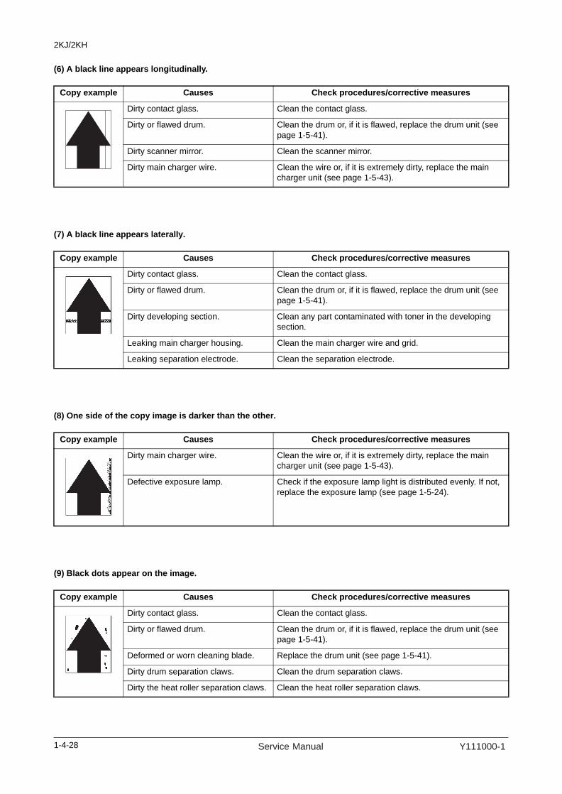
2KJ/2KH
(6) A black line appears longitudinally.
(7) A black line appears laterally.
(8) One side of the copy image is darker than the other.
(9) Black dots appear on the image.
Copy example Causes Check procedures/corrective measures
Dirty contact glass. Clean the contact glass.
Dirty or flawed drum. Clean the drum or, if it is flawed, replace the drum unit (see page 1-5-41).
Dirty scanner mirror. Clean the scanner mirror.
Dirty main charger wire. Clean the wire or, if it is extremely dirty, replace the main charger unit (see page 1-5-43).
Copy example Causes Check procedures/corrective measures
Dirty contact glass. Clean the contact glass.
Dirty or flawed drum. Clean the drum or, if it is flawed, replace the drum unit (see page 1-5-41).
Dirty developing section. Clean any part contaminated with toner in the developing section.
Leaking main charger housing. Clean the main charger wire and grid.
Leaking separation electrode. Clean the separation electrode.
Copy example Causes Check procedures/corrective measures
Dirty main charger wire. Clean the wire or, if it is extremely dirty, replace the main charger unit (see page 1-5-43).
Defective exposure lamp. Check if the exposure lamp light is distributed evenly. If not, replace the exposure lamp (see page 1-5-24).
Copy example Causes Check procedures/corrective measures
Dirty contact glass. Clean the contact glass.
Dirty or flawed drum. Clean the drum or, if it is flawed, replace the drum unit (see page 1-5-41).
Deformed or worn cleaning blade. Replace the drum unit (see page 1-5-41).
Dirty drum separation claws. Clean the drum separation claws.
Dirty the heat roller separation claws. Clean the heat roller separation claws.
1-4-28 Service Manual Y111000-1
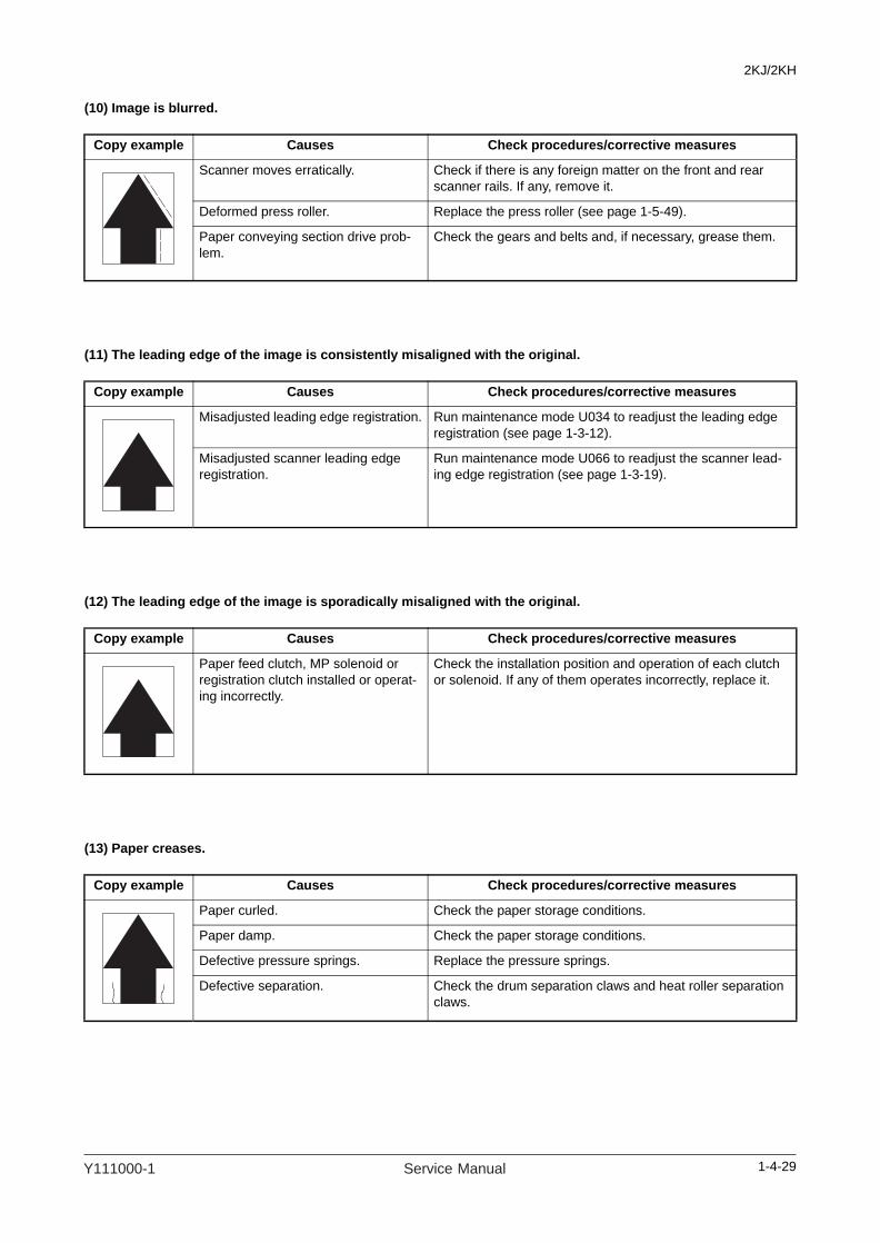
2KJ/2KH
(10) Image is blurred.
(11) The leading edge of the image is consistently misaligned with the original.
(12) The leading edge of the image is sporadically misaligned with the original.
(13) Paper creases.
Copy example Causes Check procedures/corrective measures
Scanner moves erratically. Check if there is any foreign matter on the front and rear scanner rails. If any, remove it.
Deformed press roller. Replace the press roller (see page 1-5-49).
Paper conveying section drive prob-lem.
Check the gears and belts and, if necessary, grease them.
Copy example Causes Check procedures/corrective measures
Misadjusted leading edge registration. Run maintenance mode U034 to readjust the leading edge registration (see page 1-3-12).
Misadjusted scanner leading edge registration.
Run maintenance mode U066 to readjust the scanner lead-ing edge registration (see page 1-3-19).
Copy example Causes Check procedures/corrective measures
Paper feed clutch, MP solenoid or registration clutch installed or operat-ing incorrectly.
Check the installation position and operation of each clutch or solenoid. If any of them operates incorrectly, replace it.
Copy example Causes Check procedures/corrective measures
Paper curled. Check the paper storage conditions.
Paper damp. Check the paper storage conditions.
Defective pressure springs. Replace the pressure springs.
Defective separation. Check the drum separation claws and heat roller separation claws.
1-4-29Y111000-1 Service Manual

2KJ/2KH
(14) Offset occurs.
(15) Image is partly missing.
(16) Fusing is poor.
(17) Image is out of focus.
Copy example Causes Check procedures/corrective measures
Defective cleaning blade. Replace the drum unit (see page 1-5-41).
Defective fuser unit. Check the heat roller and press roller.
Wrong types of paper. Check if the paper meets specifications. Replace paper.
Copy example Causes Check procedures/corrective measures
Paper damp. Check the paper storage conditions.
Paper creased. Change the paper.
Dirty or flawed drum. Clean the drum or, if it is flawed, replace the drum unit (see page 1-5-41).
Dirty transfer roller. Clean the transfer roller.
Copy example Causes Check procedures/corrective measures
Wrong types of paper. Check if the paper meets specifications. Replace paper.
Defective pressure springs. Replace the pressure springs.
Flawed press roller. Replace the press roller (see page 1-5-49).
Flawed fuser heater. Replace the fuser heaters (see page 1-5-51).
Copy example Causes Check procedures/corrective measures
Defective image scanning unit. Replace the image scanning unit (see page 1-5-33).
Drum condensation. Clean the drum.
1-4-30 Service Manual Y111000-1
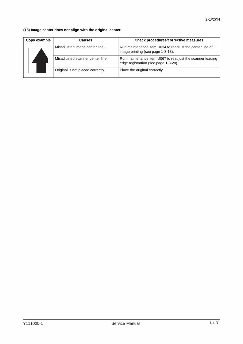
2KJ/2KH
(18) Image center does not align with the original center.
Copy example Causes Check procedures/corrective measures
Misadjusted image center line. Run maintenance item U034 to readjust the center line of image printing (see page 1-3-13).
Misadjusted scanner center line. Run maintenance item U067 to readjust the scanner leading edge registration (see page 1-3-20).
Original is not placed correctly. Place the original correctly.
1-4-31Y111000-1 Service Manual

2KJ/2KH
1-4-4 Electric problemsTroubleshooting to each failure must be in the order of the numbered symptoms.
Problem Causes Check procedures/corrective measures
(1)The machine does not operate when the main power switch is turned on.
1. The power cord is not plugged in properly.
Check the contact between the power plug and the outlet.
2. No electricity at the power outlet.
Measure the input voltage.
3. Broken power cord. Check for continuity. If none, replace the cord.
4. Defective main power switch.
Check for continuity across the contacts. If none, replace the main power switch.
5. Defective power source PWB.
With AC present, check for 24 V DC at YC1-2, YC1-3 and YC1-4 on the power source PWB. If none, replace the power source PWB.
(2)The eject motor does not operate.
1. Poor contact in the con-nector terminals.
Reinsert the connector. Also check for continuity within the con-nector cable. If none, remedy or replace the cable.
2. Defective drive transmis-sion system.
Check if the rollers and gears rotate smoothly. If not, grease the bushings and gears. Check for broken gears and replace if any.
3. Defective eject motor. Run maintenance item U030 and check if the eject motor oper-ates. If not, replace the eject motor.
4. Defective engine PWB. Run maintenance item U030 and check if the eject motor oper-ates. If not, replace the engine PWB.
(3)The cassette drive motor does not oper-ate.
1. Poor contact in the con-nector terminals.
Reinsert the connector. Also check for continuity within the con-nector cable. If none, remedy or replace the cable.
2. Defective drive transmis-sion system.
Check if the rollers and gears rotate smoothly. If not, grease the bushings and gears. Check for broken gears and replace if any.
3. Defective cassette drive motor.
Run maintenance item U030 and check if the cassette drive motor operates. If not, replace the cassette drive motor.
4. Defective cassette main PWB.
Run maintenance item U030 and check if the cassette drive motor operates. If not, replace the cassette main PWB.
(4)The scanner motor or cooling fan motor 1, 2 does not operate.
1. Poor contact in the con-nector terminals.
Reinsert the connector. Also check for continuity within the con-nector cable. If none, remedy or replace the cable.
2. Broken motor coil. Check for continuity across the coil. If none, replace the motor.
(5)The paper feed clutch, registration clutch or duplex feed clutch does not oper-ate.
1. Broken clutch coil. Check for continuity across the coil. If none, replace the clutch.
2. Poor contact in the con-nector terminals.
Reinsert the connector. Also check for continuity within the con-nector cable. If none, remedy or replace the cable.
3. Defective cassette PWB. Run maintenance item U032 and check if following terminals on the cassette PWB goes low. If not, replace the cassette PWB.Paper feed clutch: YC7-2 on the cassette PWBRegistration clutch: YC6-2 on the cassette PWBDuplex feed clutch: YC5-6 on the cassette PWB
4. Defective engine PWB. Run maintenance item U032 and check if following terminals on the engine PWB goes low. If not, replace the engine PWB.Paper feed clutch: YC7-17 on the engine PWBRegistration clutch: YC7-18 on the engine PWBDuplex feed clutch: YC7-12 on the engine PWB
1-4-32 Service Manual Y111000-1

2KJ/2KH
(6)The MP solenoid does not operate.
1. Broken solenoid coil. Check for continuity across the coil. If none, replace the solenoid.
2. Poor contact in the con-nector terminals.
Reinsert the connector. Also check for continuity within the con-nector cable. If none, remedy or replace the cable.
3. Defective cassette PWB. Run maintenance item U032 and check if following terminals on the cassette PWB goes low. If not, replace the cassette PWB.MP solenoid: YC8-2 on the cassette PWB
4. Defective engine PWB. Run maintenance item U032 and check if following terminals on the engine PWB goes low. If not, replace the engine PWB.MP solenoid: YC7-16 on the engine PWB
(7)The cleaning lamp-does not turn on.
1. Poor contact in the con-nector terminals.
Reinsert the connector. Also check for continuity within the con-nector cable. If none, remedy or replace the cable.
2. Defective cleaning lamp. Check for continuity. If none, replace the cleaning lamp.
3. Defective engine PWB. If YC3-B6 and YC3-B7 on the engine PWB is always low, replace the engine PWB.
(8)The exposure lamp does not turn on or off.
1. Poor contact in the con-nector terminals.
Reinsert the connector. Also check for continuity within the con-nector cable. If none, remedy or replace the cable.
2. Defective exposure lamp. Run maintenance item U061 and check if the exposure lamp turns on with YC2-1 and YC2-4 on the inverter PCB go low. If not, replace the exposure lamp.
3. Defective inverter PWB. Run maintenance item U061 and check if the exposure lamp turns on with YC1-3 on the inverter PWB go low. If not, replace the inverter PWB.
If the exposure lamp does not turn off with YC1-3 on the inverter PWB high, replace the inverter PWB.
4. Defective engine PWB. Run maintenance item U061 and check if YC16-4 on the engine PWB goes low. If not, replace the engine PWB.
If YC16-4 on the engine PWB is always low, replace the engine PWB.
(9)Main charging is not performed.
1. Broken main charger wire.
Replace the main charger unit (see page 1-5-43).
2. Leaking main charger housing.
Clean the main charger wire and grid.
3. The connector terminals of the high voltage PWB make poor contact.
Reinsert the connector. Also check for continuity within the con-nector cable. If none, remedy or replace the cable.
4. Defective high voltage PWB.
Check if main charging takes place when CN1-7 on the high volt-age PWB goes low while maintenance item U100 is run. If not, replace the high voltage PWB.
5. Defective engine PWB. Check if YC8-7 on the engine PWB goes low when maintenance item U100 is run. If not, replace the engine PWB.
(10)No developing bias is output.
1. The connector terminals of the high voltage PWB make poor contact.
Reinsert the connector. Also check for continuity within the con-nector cable. If none, remedy or replace the cable.
2. Defective high voltage PWB.
Check if developing bias is output when CN1-9 on the high volt-age PWB goes low while maintenance item U101 is run. If not, replace the high voltage PWB.
3. Defective engine PWB. Check if YC8-9 on the engine PWB goes low when maintenance item U101 is run. If not, replace the engine PWB.
Problem Causes Check procedures/corrective measures
1-4-33Y111000-1 Service Manual

2KJ/2KH
(11)Transfer charging is not performed.
1. The connector terminals of the high voltage PWB make poor contact.
Reinsert the connector. Also check for continuity within the con-nector cable. If none, remedy or replace the cable.
2. Defective high voltage PWB.
Check if transfer charging takes place when CN1-4 on the high voltage PWB goes low while maintenance item U101 is run. If not, replace the high voltage PWB.
3. Defective engine PWB. Check if YC8-4 on the engine PWB goes low when maintenance item U101 is run. If not, replace the engine PWB.
(12)The original size is not detected cor-rectly.
1. Original is not placed cor-rectly.
Check the original and correct if necessary.
2. Poor contact in the origi-nal detection switch or original size detection sensor connector termi-nals.
Reinsert the connector. Also check for continuity within the con-nector cable. If none, remedy or replace the cable.
3. Defective original detec-tion switch.
If the level of YC5-B8 on the engine PWB does not go low when the original detection switch is turned on and off, replace the origi-nal detection switch.
4. Defective original size detection sensor.
Check if sensor operates correctly. If not, replace it.
(13)The message requesting paper to be loaded is shown when paper is present on the cas-sette or MP tray.
1. Poor contact in the con-nector terminals of paper switch or MP paper switch.
Reinsert the connector. Also check for continuity within the con-nector cable. If none, remedy or replace the cable.
2. Defective paper switch or MP paper switch.
If the level of following terminal on PWB does not go low when the switch is turned on and off, replace the switch.Paper switch: YC2-2 on the cassette PWBMP paper switch: YC5-12 on the cassette PWB
(14)The size of paper on the cassette or MP tray is not displayed correctly.
1. Poor contact in the con-nector terminals of paper size length switch or MP paper size width switch.
Reinsert the connector. Also check for continuity within the con-nector cable. If none, remedy or replace the cable.
2. Defective paper size length switch or MP paper size width switch.
If the level of following terminal on PWB does not go low when the switch is turned on and off, replace the switch.Paper size length switch: YC9-B3, B4, B6 on the engine PWBMP paper size width switch: YC5-2 on the cassette PWB
(15)A paper jam in the paper feed, paper conveying, eject or duplex section is indi-cated when the main power switch is turned on.
1. A piece of paper torn from copy paper is caught around registra-tion switch, eject switch or duplex paper convey-ing switch.
Check visually and remove it, if any.
2. Defective switch. Run maintenance item U031 and turn switch on and off manually. Replace the switch if indication of the corresponding switch is not light.Registration switch, eject switch, duplex paper conveying switch
Problem Causes Check procedures/corrective measures
1-4-34 Service Manual Y111000-1

2KJ/2KH
(16)The message requesting cover to be closed is dis-played when the front cover or left cover is closed.
1. Poor contact in the con-nector terminals of front cover safety switch or left cover safety switch.
Reinsert the connector. Also check for continuity within the con-nector cable. If none, remedy or replace the cable.
2. Defective front cover safety switch or left cover safety switch.
Check for continuity across each switch. If there is no continuity when the switch is on, replace it.
(17)Others.
1. Wiring is broken, shorted or makes poor contact.
Check for continuity. If none, repair.
Problem Causes Check procedures/corrective measures
1-4-35Y111000-1 Service Manual

2KJ/2KH
1-4-5 Mechanical problems
Problem Causes/check procedures Corrective measures
(1)No primary paper feed.
Check if the surfaces of the following rollers or pulleys are dirty with paper powder: forwarding pulley, paper feed pulley, separa-tion pulley, registration roller, MP paper feed pulley and MP separation pad.
Clean with isopropyl alcohol.
Check if the upper/lower forwarding pulleys, forwarding pulley, paper feed pulley or sepa-ration pulley is deformed.
Replace the pulley if it is deformed (see page 1-5-3).
Check if the MP paper feed pulley or MP sep-aration pad is deformed.
Replace the pulley if it is deformed (see page 1-5-18).
Electrical problem with the following clutches and solenoid: paper feed clutch, registration clutch and MP solenoid.
See page 1-4-32.
(2)No secondary paper feed.
Check if the surfaces of the right and left reg-istration rollers are dirty with paper powder.
Clean with isopropyl alcohol.
Electrical problem with the registration clutch. See page 1-4-32.
(3)Skewed paper feed.
Width guide in a cassette installed incorrectly. Check the width guide visually and correct or replace if necessary.
Deformed width guide in a cassette. Check visually and replace any deformed guide.
Check if a pressure spring along the paper conveying path is deformed or out of place.
Repair or replace.
(4)The scanner does not travel.
Check if the scanner wire is loose. Reinstall the scanner wire (see page 1-5-26).
The scanner motor malfunctions. See page 1-4-32.
(5)Multiple sheets of paper are fed at one time.
Paper is extremely curled. Change the paper.
Check if the separation pulley is worn. Replace the separation pulley if it is worn (see page 1-5-3).
Check if the MP separation pad is worn. Replace the MP separation pad if it is worn (see page 1-5-18).
(6)Paper jams.
Paper is extremely curled. Change the paper.
Deformed guides along the paper conveying path.
Check visually and replace any deformed guides.
Check if the contact between the right and left registration rollers is correct.
Check visually and remedy if necessary.
Check if the press roller is extremely dirty or deformed.
Clean or replace the press roller.
Check if the contact between the heat roller and its separation claws is correct.
Repair if any springs are off the separation claws.
Check if the contact between the eject roller and pulley is correct.
Check visually and remedy if necessary.
(7)Toner drops on the paper conveying path.
Check if the developing unit is extremely dirty. Clean the developing unit.
1-4-36 Service Manual Y111000-1

2KJ/2KH
(8)Abnormal noise is heard.
Check if the pulleys, rollers and gears operate smoothly.
Grease the bearings and gears.
Check if the following clutches and solenoid are installed correctly: paper feed clutch, registration clutch and MP solenoid.
Correct.
Problem Causes/check procedures Corrective measures
1-4-37Y111000-1 Service Manual

2KJ/2KH
This page is intentionally left blank.
1-4-38 Service Manual Y111000-1

2KJ/2KH
1-5 Assembly and Disassembly
1-5-1 Precautions for assembly and disassembly
(1) Precautions
Before starting disassembly, press the Power key on the operation panel to off. Make sure that the Power lamp is off before turning off the main power switch. And then unplug the power cable from the wall outlet.Turning off the main power switch before pressing the power key to off may cause damage to the equipped hard disk.When fax kit is installed, be sure to disconnect the modular code before starting disassembly.When handling PWBs (printed wiring boards), do not touch parts with bare hands.The PWBs are susceptible to static charge.Do not touch any PWB containing ICs with bare hands or any object prone to static charge.Use only the specified parts to replace the fuser unit thermostat. Never substitute electric wires, as the machine may be seriously damaged.When removing the hook of the connector, be sure to release the hook.Take care not to get the cables caught.To reassemble the parts, use the original screws. If the types and the sizes of screws are not known, refer to the PARTS LIST.
(2) Drum
Note the following when handling or storing the drum.When removing the drum unit, never expose the drum surface to strong direct light.Keep the drum at an ambient temperature between -20°C/-4°F and 40°C/104°F and at a relative humidity not higher than 90% RH. Avoid abrupt changes in temperature and humidity.Avoid exposure to any substance which is harmful to or may affect the quality of the drum.Do not touch the drum surface with any object. Should it be touched by hands or stained with oil, clean it.
(3) Toner
Store the toner container in a cool, dark place.Avoid direct light and high humidity.
1-5-1Y111000-1 Service Manual

2KJ/2KH
(4) How to tell a genuine Olivetti toner container
As a means of brand protection, the Olivetti toner container utilizes an optical security technology to enable visual validation. A validation viewer is required to accomplish this.
Hold the validation viewer over the left side part of the brand protection seal on the toner container. Through each window of the validation viewer, the left side part of the seal should be seen as follows:
A black-colored band when seen through the left side windowA shiny or gold-colored band when seen through the right side window
The above will reveal that the toner container is a genuine Olivetti branded toner container, otherwise, it is a counnterfeitterfeit.
Figure 1-5-1
The brand protection seal has an incision as shown below to prohibit reuse.
Figure 1-5-2
Validation viewerValidation viewer
Brand protection seal Brand protection seal
See through
the left window
( marking)
See through
the right window
( marking)
A shiny or gold-colored band when
seen through the right side window
A black-colored band when
seen through the left side window
Incision
Cut
1-5-2 Service Manual Y111000-1

2KJ/2KH
1-5-2 Paper feed section
(1) Detaching and refitting the separation pulley
Follow the procedure below to replace the separation pulley.
Procedure1. Open the front cover and left cover.2. Pull out the cassette.
Figure 1-5-3
3. Remove the screw and remove the front left lower cover.
Figure 1-5-4
Cassette
Screw
Front left
lower cover
1-5-3Y111000-1 Service Manual

2KJ/2KH
4. Remove the screw and remove the lower paper feed unit.
Figure 1-5-5
5. Release two hooks and remove the separa-tion pulley unit from the lower paper feed unit.
Figure 1-5-6
Screw Lower paper feed unit
Hook Hook
Separation pulley unit
Separation pulley unit
Separation pulley unit
Lower paper feed unit
1-5-4 Service Manual Y111000-1

2KJ/2KH
6. Remove the separation pulley shaft from the separation pulley unit.
7. Remove the separation pulley from the sep-aration pulley shaft.
8. Replace the separation pulley and refit all the removed parts.
Figure 1-5-7
Separation pulley
Separation pulley shaft
1-5-5Y111000-1 Service Manual

2KJ/2KH
(2) Detaching and refitting the forwarding pulley and paper feed pulley
Follow the procedure below to replace the forwarding pulley and paper feed pulley.
Procedure1. Remove the lower paper feed unit (see page
1-5-3).2. Remove the drum unit (see page 1-5-41).3. Remove five screws and remove the rear
cover.
Figure 1-5-8
4. Remove the connector of the paper feed clutch.
5. Remove the paper feed clutch, stop ring and bush.
Figure 1-5-9
Screw
Screw
Screw
Screw
Screw
Rear cover
Paper feed clutch
Stop ring
Bush
1-5-6 Service Manual Y111000-1

2KJ/2KH
6. Remove the screw and remove the registra-tion guide.
Figure 1-5-10
7. Remove the screw and remove the upper paper feed unit.
Figure 1-5-11
Screw
Registration guide
Screw
Upper paper feed unit
1-5-7Y111000-1 Service Manual

2KJ/2KH
8. Remove the springs, stop ring and bush and then remove the shaft holder from the upper paper feed unit.
Figure 1-5-12
9. Remove the forwarding pulley from the upper paper feed unit.
10. Remove the paper feed pulley shaft from the upper paper feed unit.
11. Remove the collar and the paper feed pulley from the upper paper feed shaft.
12. Replace the forwarding pulley and paper feed pulley and refit all the removed parts.
Figure 1-5-13
Upper paper feed unit
Stop ring
BushSpring
Spring
Shaft holder
Forwarding pulley
Paper feed
pulley shaft
Paper feed pulley
Collar
1-5-8 Service Manual Y111000-1

2KJ/2KH
(3) Detaching and refitting the feed roller (22 ppm model only)
Follow the procedure below to replace the feed roller.
Procedure1. Remove the front left lower cover (see page
1-5-3).2. Remove three cover labels.3. Remove five screws and remove the main
body from paper feeder.
Figure 1-5-14
Screw
Cover label
Paper feeder
Cover label
Cover label
Screw
ScrewScrew
Screw
1-5-9Y111000-1 Service Manual

2KJ/2KH
4. Open the cassette left cover.5. Remove the stop ring from rear side of the
feed roller and slide the bush toward the inside.
6. Lift the rear of the feed roller upward. Slide the feed roller toward the rear side and remove the roller from the paper feeder.
Figure 1-5-15
7. Remove the gear, spring pin and two bushes from the feed roller.
8. Replace the feed roller and refit all the removed parts.
Figure 1-5-16
Feed roller
Stop ring
Bush
Feed roller
Bush
Gear
Spring pin
Bush
1-5-10 Service Manual Y111000-1
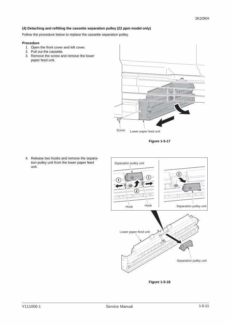
2KJ/2KH
(4) Detaching and refitting the cassette separation pulley (22 ppm model only)
Follow the procedure below to replace the cassette separation pulley.
Procedure1. Open the front cover and left cover.2. Pull out the cassette.3. Remove the screw and remove the lower
paper feed unit.
Figure 1-5-17
4. Release two hooks and remove the separa-tion pulley unit from the lower paper feed unit.
Figure 1-5-18
Screw Lower paper feed unit
Hook Hook
Separation pulley unit
Separation pulley unit
Separation pulley unit
Lower paper feed unit
1-5-11Y111000-1 Service Manual

2KJ/2KH
5. Remove the separation pulley shaft from the separation pulley unit.
6. Remove the cassette separation pulley from the separation pulley shaft.
7. Replace the cassette separation pulley and refit all the removed parts.
Figure 1-5-19
Cassette separation pulley
Separation pulley shaft
1-5-12 Service Manual Y111000-1

2KJ/2KH
(5) Detaching and refitting the cassette forwarding pulley and cassette paper feed pulley (22 ppm model only)
Follow the procedure below to replace the cassette forwarding pulley and cassette paper feed pulley.
Procedure1. Remove the feed roller (see page 1-5-9).2. Remove the lower paper feed unit (see page
1-5-11).3. Remove the screw and the pin and then
remove the cassette rear cover.
Figure 1-5-20
4. Remove the connector of the cassette paper feed clutch.
5. Remove the stop ring and remove the cas-sette paper feed clutch.
6. Remove the stop ring and the bush.
Figure 1-5-21
Screw
Pin
Cassette rear cover
Cassette paper
feed clutchStop ring
Stop ring
Bush
1-5-13Y111000-1 Service Manual
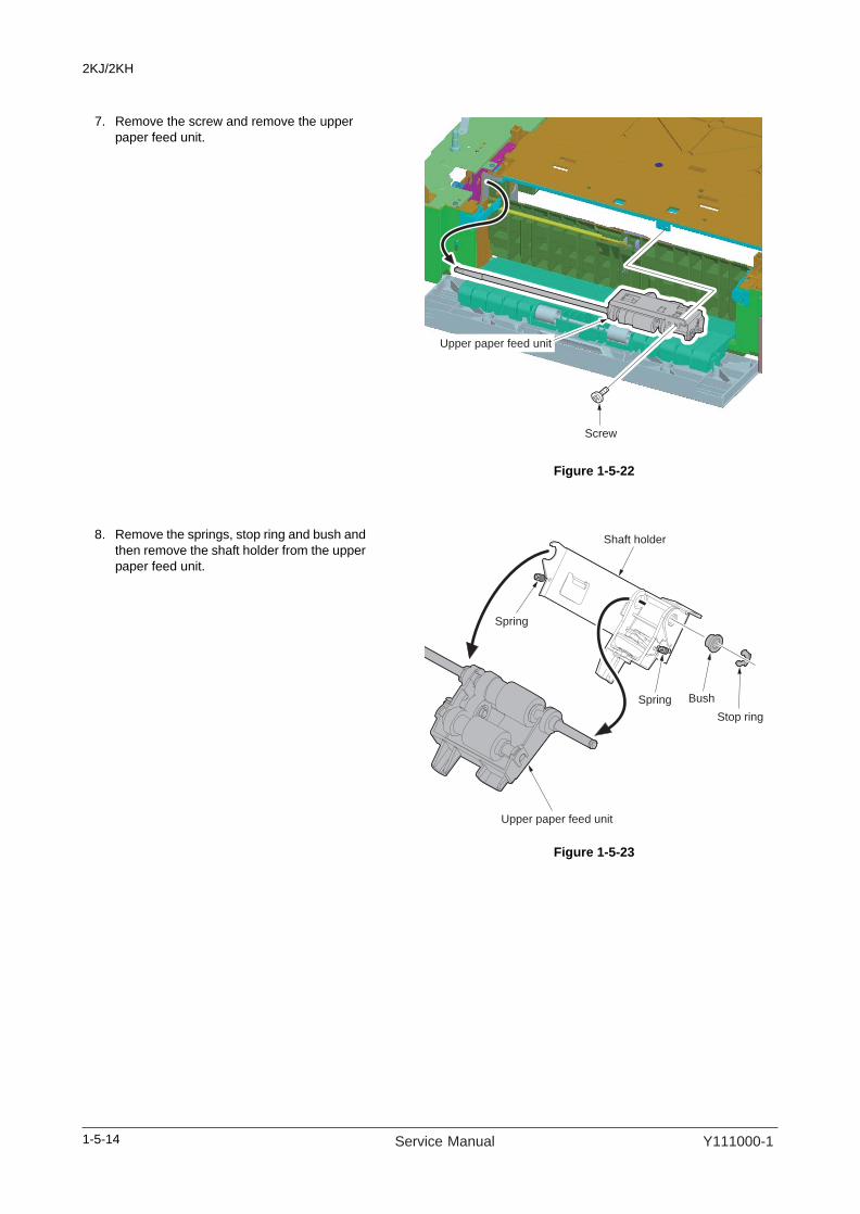
2KJ/2KH
7. Remove the screw and remove the upper paper feed unit.
Figure 1-5-22
8. Remove the springs, stop ring and bush and then remove the shaft holder from the upper paper feed unit.
Figure 1-5-23
Screw
Upper paper feed unit
Upper paper feed unit
Stop ring
BushSpring
Spring
Shaft holder
1-5-14 Service Manual Y111000-1

2KJ/2KH
9. Remove the cassette forwarding pulley from the upper paper feed unit.
10. Remove the paper feed pulley shaft from the upper paper feed unit.
11. Remove the collar and the cassette paper feed pulley from the upper paper feed shaft.
12. Replace the cassette forwarding pulley and cassette paper feed pulley and refit all the removed parts.
Figure 1-5-24
Cassette forwarding pulley
Paper feed pulley shaft
Cassette paper feed pulley
Collar
1-5-15Y111000-1 Service Manual

2KJ/2KH
(6) Detaching and refitting the paper conveying unit
Follow the procedure below to maintenance of the paper feed section.
Procedure1. Remove the drum unit (see page 1-5-41).2. Remove the lower paper feed unit (see page
1-5-11).3. Remove the stop ring and strap from the
rear side of the left cover.Remove the stop ring and stopper from the front side of the left cover.
Figure 1-5-25
Stopper
Stop ring
Strap
Stop ring
1-5-16 Service Manual Y111000-1
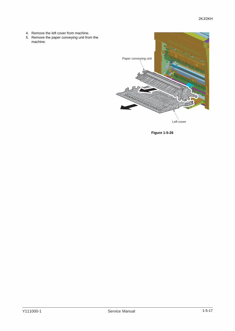
2KJ/2KH
4. Remove the left cover from machine.5. Remove the paper conveying unit from the
machine.
Figure 1-5-26
Left cover
Paper conveying unit
1-5-17Y111000-1 Service Manual

2KJ/2KH
(7) Detaching and refitting the MP paper feed pulley and MP separation pad
Follow the procedure below to replace the MP paper feed pulley and MP separation pad.
Procedure1. Open the front cover and remove the waste
toner box. Pull out the cassette.2. Remove the screw and remove the front left
lower cover (see page 1-5-3).3. Remove the paper conveying unit (see page
1-5-16).4. Remove the stop ring and bush from the
front side of the machine.
Figure 1-5-27
5. Remove the rear cover (see page 1-5-6).6. Remove three screws and remove the MP
drive unit.
Figure 1-5-28
BushStop ring
Screw
Screws
MP drive unit
1-5-18 Service Manual Y111000-1

2KJ/2KH
7. Remove the stop ring, gear and bush.
Figure 1-5-29
8. Temporarily push the MP paper feed pulley unit into the rear side to unlock the front side and then remove it from the machine.
Figure 1-5-30
Bush
Gear
Stop ring
MP paper feed pulley unit
1-5-19Y111000-1 Service Manual

2KJ/2KH
9. Remove the stop ring, MP paper guide, spring pin and the MP paper feed pulley.
Figure 1-5-31
10. Push the inserted parts of the MP separation pad and remove the pad from the machine.
11. Replace the MP paper feed pulley and MP separation pad and refit all the removed parts.
Figure 1-5-32
MP paper guide
Stop ring
MP paper feed pulley
Spring pin
MP paper feed pulley shaft
MP separation pad
MP separation pad
1-5-20 Service Manual Y111000-1

2KJ/2KH
(8) Detaching and refitting the left registration roller
Follow the procedure below to replace the left registration roller.
Procedure1. Remove the paper conveying unit (see page
1-5-16).2. Release the stoppers at the front and rear
side, and then remove the left registration roller from the paper conveying unit.
Figure 1-5-33
3. Remove two stoppers, gear and two bushes.
4. Replace the left registration roller and refit all the removed parts.
Figure 1-5-34
Left registration roller unit
Paper conveying unit
Stopper
Left registration roller
Stopper
Stopper
Bush
Bush
Gear
1-5-21Y111000-1 Service Manual

2KJ/2KH
(9) Detaching and refitting the right registration roller
Follow the procedure below to replace the right registration roller.
Procedure1. Remove the drum unit (see page 1-5-41).2. Remove the rear cover (see page 1-5-6).3. Remove the connector and remove the reg-
istration clutch.
Figure 1-5-35
4. Remove the stop ring.5. Remove the right registration roller from the
machine.
Figure 1-5-36
Registration clutch
Right registration roller
Stop ring
1-5-22 Service Manual Y111000-1

2KJ/2KH
6. Remove two bushes and gear.7. Replace the right registration roller and refit
all the removed parts.
Figure 1-5-37
Bush
Bush
Gear
Right registration roller
1-5-23Y111000-1 Service Manual

2KJ/2KH
1-5-3 Optical section
(1) Detaching and refitting the exposure lamp
Follow the procedure below to replace the exposure lamp.
Procedure1. Remove the original cover or the document
processor.2. Remove two screws and remove the right
upper cover.Remove the contact glass.
Figure 1-5-38
3. Open the front cover and left cover.4. Remove the front left cover (see ).5. Release five hooks and both and then
remove the front scanner cover.6. Remove two screws and remove the rear
upper cover.
Figure 1-5-39
Right upper coverScrew
Screw
Contact glass
Screw
Rear upper cover
Front scanner cover
Hook
Hook
Front scanner cover
Hook
Hook
Hook
Both
Screw
1-5-24 Service Manual Y111000-1
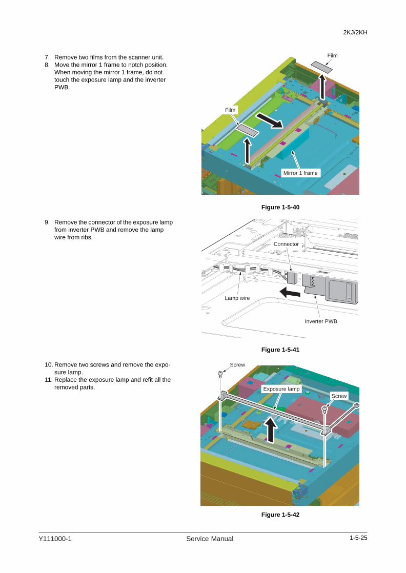
2KJ/2KH
7. Remove two films from the scanner unit.8. Move the mirror 1 frame to notch position.
When moving the mirror 1 frame, do not touch the exposure lamp and the inverter PWB.
Figure 1-5-40
9. Remove the connector of the exposure lamp from inverter PWB and remove the lamp wire from ribs.
Figure 1-5-41
10. Remove two screws and remove the expo-sure lamp.
11. Replace the exposure lamp and refit all the removed parts.
Figure 1-5-42
Film
Film
Mirror 1 frame
Connector
Inverter PWB
Lamp wire
Screw
Screw
Exposure lamp
1-5-25Y111000-1 Service Manual

2KJ/2KH
(2) Detaching and refitting the scanner wires
Take the following procedure when the scanner wires are broken or to be replaced.
(2-1) Detaching the scanner wires
Procedure1. Remove the exposure lamp (see page 1-5-
24).2. Open the left cover.3. Release six hooks and both and then
remove the left middle cover.
Figure 1-5-43
4. Release five hooks and two bothes and then remove the left upper cover.
Figure 1-5-44
Left middle cover
Hook
Hook
Left middle coverBoth
HookHook
Hook
Hook
Left upper cover
Left upper cover
Hook
Hook
Both
Both
Hook
Hook
Hook
1-5-26 Service Manual Y111000-1

2KJ/2KH
5. Remove the screw and remove the slit retainer and slit glass.
Figure 1-5-45
6. Remove two wire guides.7. Remove the inverter wire from the inverter
PWB.
Figure 1-5-46
Screw
Slit retainer
Slit glass
Inverter PWBWire guide
Wire guide
Inverter wire
1-5-27Y111000-1 Service Manual

2KJ/2KH
8. Remove each screw and remove front and rear wire holder plates.Remove the mirror 1 frame from the scanner unit.
Figure 1-5-47
9. Remove the round terminals from the scan-ner wire springs.
10. Remove the scanner wires.
Figure 1-5-48
Screw Screw
Mirror 1 frame
Front wire
retainer
Rear wire
retainer
Scanner wire spring
Scanner wire spring
Round terminal
Round terminal
1-5-28 Service Manual Y111000-1

2KJ/2KH
1-5-29
(2-2) Fitting the scanner wires
NOTEWhen fitting the wires, be sure to use those specified below.Machine front: (P/N: AVGR00575W), grayMachine rear: (P/N: AVGR00574S), black
Fitting requires the following toolsTwo frame securing tools (P/N AVGR03672L)Two scanner wire stoppers (P/N 417928N)
Procedure1. Remove the rear cover.
Figure 1-5-49
2. Remove the screw and remove the scanner wire drum gear from the rear side of the machine.
3. Remove the stop ring and bush.
Figure 1-5-50
Right middle cover
Right middle cover
Screw
Screw
Hook
Hook
Both
Both
Bush
Stop ring
Screw
Scanner wire
drum gear
Y111000-1 Service Manual

2KJ/2KH
4. Remove the stop ring and bush from the front of the machine.
5. Remove the scanner wire drum shaft from the scanner unit.
Figure 1-5-51
6. Insert the locating ball on each of the scan-ner wires into the hole in the respective scanner wire drum and wind the scanner wire three turns inward and four turns out-ward.With the locating ball as the reference point, wind the shorter end of each of the wires outward.
7. Secure the scanner wires using the scanner wire stoppers.
Figure 1-5-52
Scanner wire drum shaft
Bush
Stop ring
Three turns inward
Three turns inward
Four turns outward
Four turns outward
Locating ball
Scanner wiredrum
Scanner wire stopper
Scanner wire stopper
1-5-30 Service Manual Y111000-1

2KJ/2KH
8. Refit the scanner wire drum shaft to the scanner unit.
9. Insert the two frame securing tools into the positioning holes at the front and rear of the scanner unit to fix the mirror 2 frame in posi-tion.
Figure 1-5-53
10. Loop the outer ends of the scanner wires around the outer grooves in the pulleys on the mirror 2 frame, winding from below to above. .......................................................................................................................... (1)
11. Hook the round terminals onto the catches inside the scanner unit. ............................................................... (2)12. Loop the inner ends of the scanner wires around the grooves in the pulleys at the left of the scanner unit,
winding from below to above. .......................................................................................................................... (3)13. Loop the scanner wires around the inner grooves in the pulleys on the mirror 2 frame, winding from
above to below................................................................................................................................................. (4)14. Wind the scanner wires around the grooves in the scanner wire guides at the left of the scanner unit. ......... (5)15. Hook the round terminals onto the scanner wire springs................................................................................. (6)
Figure 1-5-54
Frame securing tool
Mirror 2 frame
Frame securing tool
1-5-31Y111000-1 Service Manual

2KJ/2KH
16. Remove two scanner wire stoppers and frame securing tools.
17. Focusing on the locating ball of the wire drum, move aside the wires to inside.
18. Move the mirror 2 frame from side to side to correctly locate the wires in position.
19. Put the mirror 1 frame on the scanner rail and move it toward the left side of the machine.
20. Insert the frame securing tools into the posi-tioning holes (leftmost holes) at the front and rear of the scanner unit and screw the mirror 1 frame while securing both the mirror 1 frame and the mirror 2 frame.
21. Remove two frame securing tools.22. Refit all the removed parts.
Figure 1-5-55
Frame securing tool
Frame securing tool
Mirror 2 frame
Mirror 1 frame
1-5-32 Service Manual Y111000-1

2KJ/2KH
(3) Detaching and refitting the ISU (reference)
Follow the procedure below to replace the ISU.
Procedure1. Remove the contact glass (see page 1-5-
24).2. Remove four screws and remove the ISU
cover.
Figure 1-5-56
3. Remove the CCD wire from the CCD PWB.
Figure 1-5-57
ISU cover
Screws
Screws
CCD wire
CCD PWB
1-5-33Y111000-1 Service Manual
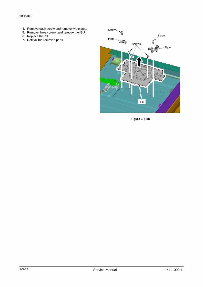
2KJ/2KH
4. Remove each screw and remove two plates.5. Remove three screws and remove the ISU6. Replace the ISU.7. Refit all the removed parts.
Figure 1-5-58
Screws
Plate
Screw
Screw
Plate
ISU
1-5-34 Service Manual Y111000-1

2KJ/2KH
(4) Detaching and refitting the laser scanner unit
Follow the procedure below to replace the laser scanner unit.
Procedure1. Remove the original cover or the document
processor.2. Remove the rear cover (see page 1-5-6).
Remove the front left cover (see page 1-5-47).Remove the right upper cover, contact glass, rear upper cover and front scanner cover (see page 1-5-24).Remove the left middle cover, left upper cover and slit glass (see page 1-5-26).Remove the right middle cover (see page 1-5-29).
3. Remove the screw and release three hooks and then remove the front right cover.
Figure 1-5-59
Front right cover
Screw
Front right
coverHook
Hook
Hook
1-5-35Y111000-1 Service Manual

2KJ/2KH
4. Remove two screws and release six hooks and two both, and then remove the right middle cover.
Figure 1-5-60
5. Remove two screws and remove the shield cover.
Figure 1-5-61
Right lower cover
Right lower
cover
Screw
Screw
Hook
Hook
Hook
Hook
Hook
Hook
Both
Both
Shield coverScrew
Screw
1-5-36 Service Manual Y111000-1

2KJ/2KH
6. Remove YC5, YC15 and YC16 connectors of the engine PWB.
7. Remove YC5 connector of the main PWB.
Figure 1-5-62
8. Remove four pins and remove the scanner unit.
Figure 1-5-63
YC5
YC15
YC16YC5
Engine PWBMain PWB
Pin
Pin
Pin
Scanner unit
Pin
1-5-37Y111000-1 Service Manual

2KJ/2KH
9. Remove the screw and remove the eject cover.
Figure 1-5-64
10. Remove the screw and remove the inner rear cover.
Figure 1-5-65
Eject cover
Screw
Inner rear cover
Screw
1-5-38 Service Manual Y111000-1

2KJ/2KH
11. Release two hooks and both and then remove the eject tray.
Figure 1-5-66
12. Remove four screws and two connectors and remove the laser scanner unit.
13. Replace the laser scanner unit and refit all the removed parts.
Figure 1-5-67
Eject tray
BothHook
Eject tray
Hook
Screw
Connector
Connector
Screw
Screw
Laser scanner
unit
Screw
1-5-39Y111000-1 Service Manual

2KJ/2KH
(5) Adjusting the longitudinal squareness (reference)
Perform the following adjustment if the leading and trailing edges of the copy image are laterally skewed (lateral square-ness not obtained).
Caution:Adjust the deflection in the paper at the registration roller first (see page 1-3-15). Check for the longitudinal squareness of the copy image, and if it is not obtained, perform the longitudinal squareness adjustment.Before making the following adjustment, output a VTC-PG2 pattern in maintenance item U993 to use as the original for the adjustment.
Procedure
Figure 1-5-68
Figure 1-5-69
Yes
No
Press the start key and make a test copy at 100% magnification.
Start
Remove the contact glass. Loosen the two screws and adjust the position of the mirror 2 frame.For copy example 1, move the frame in the direction of the white arrow ( ).For copy example 2, move the frame in the direction of the black arrow ( ).
End
Is the image correct?
Place the original on the contact glass.
Retighten the two screws and refit the contact glass.
Original Copy example 1
Copy example 2
Screws
1-5-40 Service Manual Y111000-1

2KJ/2KH
1-5-4 Drum section
(1) Detaching and refitting the drum unit
Follow the procedure below to replace the drum unit.
CautionsAvoid direct sunlight or strong light when detaching and refitting the drum unit.Never touch the drum surface when holding the drum unit.
Procedure1. Open the front cover and left cover. Remove
the waste toner box and toner container.2. Remove the screw holding the developing
release lever.3. Pull the developing release lever and
release the developing unit.
Figure 1-5-70
4. Remove the screw and the connector and then remove the drum unit.
5. Replace the drum unit and refit all the removed parts.
6. when the periodic maintenance, perform maintenance mode U251 (clearing the maintenance count) (see page 1-3-45).
Figure 1-5-71
Developing release lever
Screw
Drum unit
Connector
Screw
1-5-41Y111000-1 Service Manual

2KJ/2KH
(2) Detaching and refitting the drum separation claws
Follow the procedure below to replace the drum separation claws.
CautionsAvoid direct sunlight or strong light when detaching and refitting the drum unit.Never touch the drum surface when holding the drum unit.
Procedure1. Remove the drum unit (see page 1-5-41).2. Push the drum separation claws with the
minus driver from the top of the hole and remove the claws.
3. Replace the drum separation claws and refit all the removed parts.
Figure 1-5-72
Hole
Drum separation claw
Drum separation claw
Drum separation claw
Drum separation claw
1-5-42 Service Manual Y111000-1

2KJ/2KH
(3) Detaching and refitting the main charger unit
Follow the procedure below to replace the main charger unit.
Procedure1. Open the front cover and remove the waste
toner box.2. While lifting the main charger unit toward the
upper right, remove the unit.3. While pressing the main charger release
lever in the direction indicated by the arrow at the removal stopper position to release the removal stopper, remove the main charger unit from the machine.
4. Replace the main charger unit and refit all the removed parts.
Figure 1-5-73
Main charger unit
Main charger
release lever
1-5-43Y111000-1 Service Manual

2KJ/2KH
1-5-5 Developing section
(1) Detaching and refitting the developing unit
Follow the procedure below to replace the developing unit.
Procedure1. Remove the drum unit (see page 1-5-41).2. While lifting the developing unit a little,
remove the unit from the machine.3. Replace the developing unit and refit all the
removed parts.4. Perform maintenance mode U130 (initial
setting for the developing unit) (see page 1-3-36).
5. Perform maintenance mode U157 (clearing the developing drive time) (see page 1-3-38).
Figure 1-5-74
Developing unit
1-5-44 Service Manual Y111000-1

2KJ/2KH
1-5-6 Transfer section
(1) Detaching and refitting the transfer roller
Follow the procedure below to replace the transfer roller.
Procedure1. Remove the paper conveying unit (see page
1-5-16).2. Remove front and rear inserted parts and
remove the transfer roller unit from the paper conveying unit.
Figure 1-5-75
3. Remve two collars A, two collars B, gear, two stoppers and two bushes from transfer roller.
Figure 1-5-76
Transfer roller unit
Paper conveying unit
Inserted part
Bush
Collar A
Gear
Stopper
Bush
Stopper
Collar B
Collar A
Collar B
Transfer roller
1-5-45Y111000-1 Service Manual
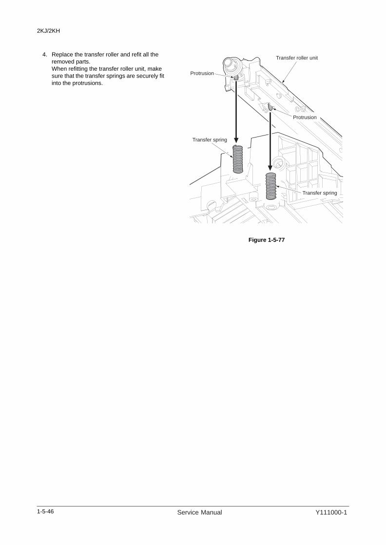
2KJ/2KH
4. Replace the transfer roller and refit all the removed parts.When refitting the transfer roller unit, make sure that the transfer springs are securely fit into the protrusions.
Figure 1-5-77
Transfer roller unit
Transfer spring
Protrusion
Protrusion
Transfer spring
1-5-46 Service Manual Y111000-1

2KJ/2KH
1-5-7 Fuser section
Caution
(1) Detaching and refitting the fuser unit
Follow the procedure below to check or replace the fuser unit.
Procedure1. Open the front cover and left cover.2. Remove the screw and release three
inserted parts and then remove the front left cover.
Figure 1-5-78
3. Remove the screw and two connectors and then remove the fuser unit.
Figure 1-5-79
Front left cover
Inserted part
Screw
Inserted part
Fuser unit
Screw
Connectors
1-5-47Y111000-1 Service Manual

2KJ/2KH
4. Replace the fuser unit and refit all the removed parts.After connecting the connector, be sure to hitch the fuser thermistor wire to both the notch position and the hook of the fuser unit.
Figure 1-5-80
Hook
Notch position
Fuser thermistor wire
1-5-48 Service Manual Y111000-1

2KJ/2KH
(2) Detaching and refitting the press roller
Follow the procedure below to replace the press roller.
Procedure1. Remove the fuser unit (see page 1-5-47).2. Remove two screws and open the fuser unit.3. Separate the right and left fuser unit.
Figure 1-5-81
4. Remove the screw and release two hooks and then remove the press roller guide from the left fuser unit.
Figure 1-5-82
Right fuser unit
Left fuser unit
Fuser unit
Screw
Screw
Press roller guide
Hook
Hook
Screw
Left fuser unit
1-5-49Y111000-1 Service Manual

2KJ/2KH
5. Remove the press roller from left fuser unit.CautionsRemove the press roller carefully not to scratch its surface.When removing it, be careful not to drop and lose the bush.
6. Replace the press roller and refit all the removed parts.
Figure 1-5-83
Press roller
Left fuser unit
Bush
1-5-50 Service Manual Y111000-1

2KJ/2KH
(3) Detaching and refitting the fuser heater
Follow the procedure below to replace the fuser heater.
Procedure1. Remove the fuser unit (see page 1-5-47).2. Remove two positive terminals of fuser
heater wires from the fuser unit.CautionRemove the positive terminals while press-ing their protrusions.
3. Remove two fuser heater wires from ribs of the fuser unit.CautionMake sure that the fuser heater wires are not removed from the positive terminals.
Figure 1-5-84
4. Separate the right and left fuser unit (see page 1-5-49).
5. Pull out the fuser heater wire from the rear side of the right fuser unit and stretch it straight.
Figure 1-5-85
Positive terminal
Protrusion
Fuser heater wire
Fuser unit
Positive terminal
Fuser heater wire
Fuser heater wire
Right fuser unit
1-5-51Y111000-1 Service Manual

2KJ/2KH
6. Release hooks at the front side of the right fuser unit and pull out the fuser heater.CautionDo not touch the glass section of the fuser heater.
Figure 1-5-86
7. Replace the fuser heater.8. Straighten the fuser heater wire in the rear
side of the new fuser heater, and insert it from the front side of the right fuser unit.
9. Fit both the protrusions in the front and rear sides of the fuser heater into the notch posi-tions of the right fuser unit.Insert the wire between the hooks in the front side of the right fuser unit until it clicks to secure it.
Figure 1-5-87
Fuser heater
Hook
Right fuser unit
Hook
Protrusion
Rear side
Protrusion
Hook
Front side
1-5-52 Service Manual Y111000-1
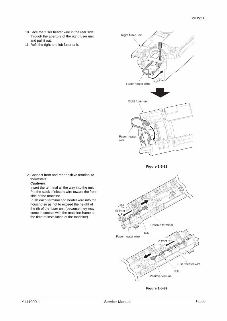
2KJ/2KH
10. Lace the fuser heater wire in the rear side through the aperture of the right fuser unit and pull it out.
11. Refit the right and left fuser unit.
Figure 1-5-88
12. Connect front and rear positive terminal to thermstats.CautionsInsert the terminal all the way into the unit.Put the slack of electric wire toward the front side of the machine.Push each terminal and heater wire into the housing so as not to exceed the height of the rib of the fuser unit (because they may come in contact with the machine frame at the time of installation of the machine).
Figure 1-5-89
Fuser heater wire
Fuser heater
wire
Right fuser unit
Right fuser unit
Positive terminal
Fuser heater wireRib
Rib
To front
To front
Positive terminal
Fuser heater wire
1-5-53Y111000-1 Service Manual

2KJ/2KH
(4) Detaching and refitting the heat roller separation claws
Follow the procedure below to replace the heat roller separation claws.
Procedure1. Separate the right and left fuser unit (see
page 1-5-49).2. Release four hooks and remove the fuser
guide from the right fuser unit.
Figure 1-5-90
3. Remove the springs and remove the heat roller separation claws.CautionWhen removing them, be careful not to touch the tip of the claw.
4. Replace the heat roller separation claws and refit all the removed parts.CautionWhen fitting the separation claws, be careful not to scratch the surface of the heat roller.
Figure 1-5-91
Heat roller guide
Hook
Hook
Hook
Hook
Right fuser unit
Heat roller separation claws
Right fuser unit
Heat roller separation claw
Spring
1-5-54 Service Manual Y111000-1

2KJ/2KH
(5) Detaching and refitting the heat roller
Follow the procedure below to replace the heat roller.
Procedure1. Separate the right and left fuser unit (see
page 1-5-49).2. Remove the fuser heater (see page 1-5-51).3. Remove the heat roller separation claws
(see page 1-5-54).4. Press the heat roller bush in the rear side of
the right fuser unit from outside to make the roller removable.
Figure 1-5-92
5. Remove the heat roller, heat roller bush and heat roller gear.CautionRemove the heat roller, with the heat roller bush in the front side being mounted.
Figure 1-5-93
Heat roller bush
Right fuser unit
Heat roller
Right fuser unit
Heat roller bush
Heat roller gear
1-5-55Y111000-1 Service Manual
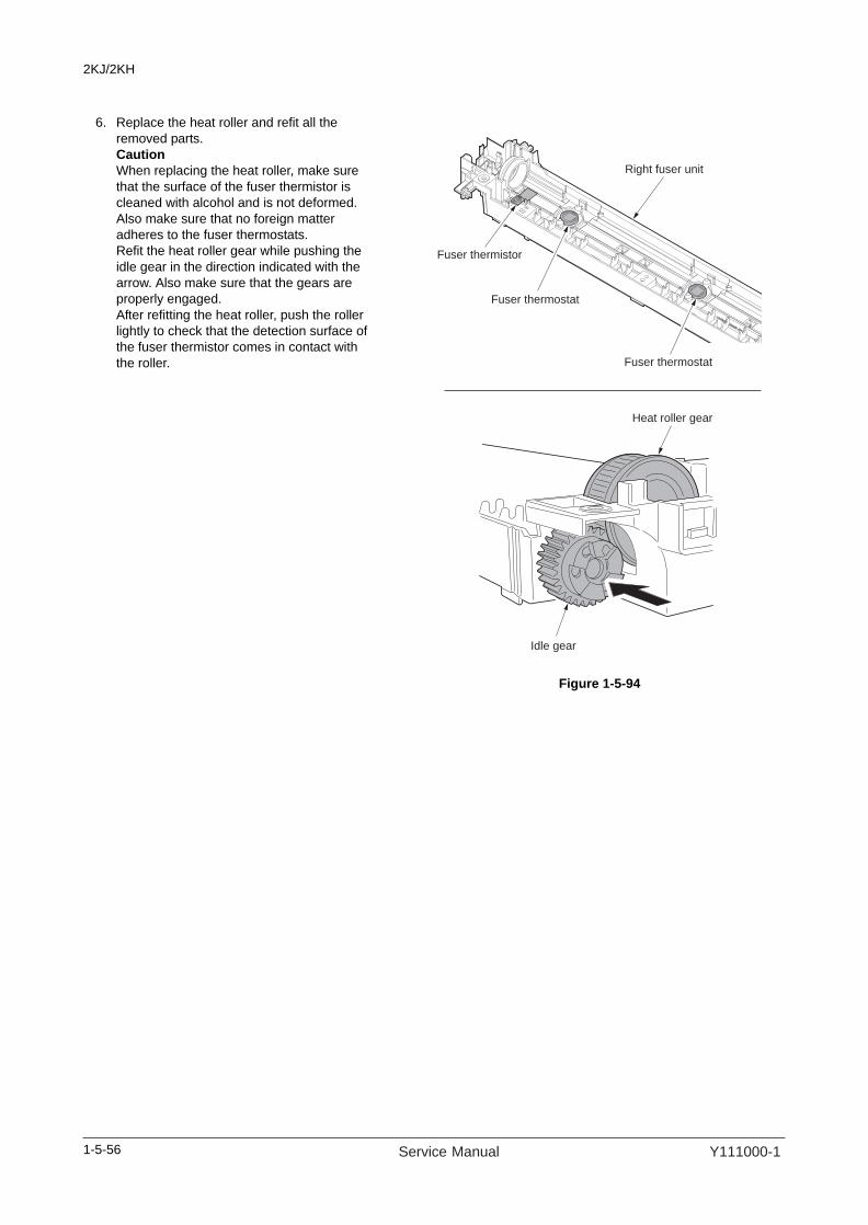
2KJ/2KH
6. Replace the heat roller and refit all the removed parts.CautionWhen replacing the heat roller, make sure that the surface of the fuser thermistor is cleaned with alcohol and is not deformed. Also make sure that no foreign matter adheres to the fuser thermostats.Refit the heat roller gear while pushing the idle gear in the direction indicated with the arrow. Also make sure that the gears are properly engaged.After refitting the heat roller, push the roller lightly to check that the detection surface of the fuser thermistor comes in contact with the roller.
Figure 1-5-94
Fuser thermistor
Fuser thermostat
Fuser thermostat
Right fuser unit
Idle gear
Heat roller gear
1-5-56 Service Manual Y111000-1

2KJ/2KH
(6) Detaching and refitting the fuser thermistor
Follow the procedure below to replace the fuser thermistor.
Procedure1. Separate the right and left fuser unit (see
page 1-5-49).2. Remove the heat roller (see page 1-5-55).3. Remove the screw and remove the fuser
thermistor.4. Replace the fuser thermistor and refit all the
removed parts.CautionRestore the fuser thermistor wire to its origi-nal correct position.After refitting the heat roller, push the roller lightly to check that the detection surface of the fuser thermistor comes in contact with the roller.
Figure 1-5-95
Fuser thermistor
Right fuser unit
Screw
1-5-57Y111000-1 Service Manual

2KJ/2KH
(7) Detaching and refitting the fuser thermostat
Follow the procedure below to replace the fuser thermostat.
CautionsBe sure to replace it after finding the cause of failure.If the cause is not found, do not replace only the component in question but the entire unit.If C6000 or C6020 occurs, replace the thermostat after resolving the problem.Before replacement, conduct continuity check for the thermostat.
Procedure1. Remove the fuser unit (see page 1-5-47).2. Remove two positive terminals from fuser
thermostat.3. Remove two screws and remove the fuser
thermostat.4. Replace the fuser thermostat and refit all the
removed parts.CautionsInsert the terminal all the way into the unit.Put the slack of electric wire toward the front side of the machine.Push each terminal and heater wire into the housing so as not to exceed the height of the rib of the fuser unit (because they may come in contact with the machine frame at the time of installation of the machine).
Figure 1-5-96
5. Use a thickness gauge to check that the clearance between the fuser thermostat and the heat roller is within the reference value.Reference value: 0.7 to 1.5 mm
Figure 1-5-97
Fuser thermostat
Screw
Screw
Positive terminal
Positive terminal
0.7 to 1.5 mm
1-5-58 Service Manual Y111000-1

2KJ/2KH
(8) Adjusting front position of the fuser unit (adjusting lateral squareness)
Follow the procedure below if the drum is not parallel to the fuser unit and therefore paper is not fed straight to the fuser section and the trailing edge of image on either the front or rear side becomes longer.
Procedure
Figure 1-5-98
Figure 1-5-99
Tighten the screws.
Refit the front left cover.
Remove the front left cover (see page 1-5-47).
Loosen the screw holding the fuser unit.
For copy example 1:
Move the adjusting spacer in the direction
of the white arrow ( ) to raise the front
position of the fuser unit.
For copy example 2:
Move the adjusting spacer in the direction
of the black arrow ( ) to lower the front
position of the fuser unit.
Yes
No
Press the start key and make
a test copy at 100 % magnification.
Start
End
Is the image correct?
Place the original on the contact
glass.
Original Copyexample 1
Copyexample 2
Screw Adjusting spacer
Fuser unit
1-5-59Y111000-1 Service Manual

2KJ/2KH
1-5-8 Others
(1) Detaching and refitting the eject unit
Follow the procedure below to replace the eject unit.
Procedure1. Remove the rear cover (see page 1-5-6).2. Remove YC14 connector of the engine
PWB.3. Remove the wire of the connector from
clamp and ribs.
Figure 1-5-100
4. Remove the front left cover (see page 1-5-47).
5. Remove the left middle cover (see page 1-5-26).
6. Remove the eject cover (see page 1-5-38).7. Remove the screw. Slide the eject unit
toward the front side and pull out the inserted part section.
Figure 1-5-101
Clamp
Engine PWB
YC14Rib
Rib
Connector
Screw
Eject unit
Inserted part
1-5-60 Service Manual Y111000-1
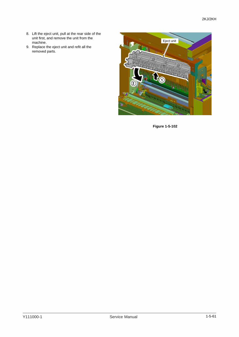
2KJ/2KH
8. Lift the eject unit, pull at the rear side of the unit first, and remove the unit from the machine.
9. Replace the eject unit and refit all the removed parts.
Figure 1-5-102
Eject unit
1-5-61Y111000-1 Service Manual

2KJ/2KH
(2) Direction of installing the principal fan motors
When detaching or refitting the cooling fan motor 1 or 2, be careful of the airflow direction (intake or exhaust).
Figure 1-5-103
Cooling fan motor 1
(Rating label: outside)
Cooling fan motor 2
(Rating label: inside)
Intake
Exhaust
1-5-62 Service Manual Y111000-1

2KJ/2KH
1-6 Requirements on PWB Replacement
1-6-1 Upgrading the firmwareFollow the procedure below to upgrade the firmware of main, engine and MMI.
Firmware upgrading requires the following tools:Compact Flash (Products manufactured by SANDISK are recommended.)
NOTEWhen writing data to a new Compact Flash from a computer, be sure to format it in advance.
Procedure1. Perform maintenance item U000 (mainte-
nance report output) and check U019 ROM version.
2. Press the power key on the operation panel to off. Make sure that the Power lamp is off before turning off the main power switch. And then unplug the power cable from the wall outlet.
3. Remove the screw and remove the slot cover.
4. Insert Compact Flash in a notch hole of the machine.Insert the surface of Compact Flash toward the machine rear.
5. Insert the power plug and turn the main power switch on. Upgrading firmware starts.Caution:Never turn the main power switch off during upgrading.
Figure 1-6-16. [Completed] is displayed on the touch panel
when upgrading is complete.7. Turn the main power switch off and unplug
the power cable from the wall outlet.8. Remove Compact Flash from the machine.9. Refit the slot cover.10. Insert the power plug and turn the main
power switch on.11. Perform maintenance item U000 (mainte-
nance report output) and check that U019 ROM version has been upgraded.
Compact Flash
Screw
Slot cover
1-6-1Y111000-1 Service Manual

2KJ/2KH
1-6-2 Adjustment-free variable resistors (VR)The variable resistors listed below are set at the factory prior to shipping and cannot be adjusted in the field.High voltage PWB: VR401APC PWB: VR1
1-6-3 Remarks on main PWB and engine PWB replacementWhen replacing the main PWB or engine PWB, remove the EEPROM (YS3) or EEPROM (U3) from the PWB that hasbeen removed and then reattach it to the new PWB.
Figure 1-6-2
Engine PWB
Main PWB
EEPROM
EEPROM(U3)
EEPROM(YS3)
EEPROM
1-6-2 Service Manual Y111000-1

2KJ/2KH
2-1 Mechanical construction
2-1-1 Paper feed sectionThe paper feed section conveys paper from the cassette (one cassette is standard for 18 ppm model/two cassettes arestandard for 22 ppm model) or MP tray to the left and right registration rollers, at which point secondary feed takes placeand the paper travels to the transfer section in sync with the printing timing.Cassette can hold up to 300 (80 g/m2) sheets of paper. Paper is fed from the cassette by the rotation of the forwarding pul-ley and paper feed pulley. The separation pulley prevents multiple sheets from being fed at one time, via the torque limiter.The MP tray can hold up to 100 (80 g/m2) sheets of paper. Paper is fed from the MP tray by the rotation of the MP paperfeed pulley.
Figure 2-1-1 Paper feed section
5
12
10
20
29
19
87
1817
1
4
36
11
14
13
16
15
(1) Forwarding pulley(2) Paper feed pulley(3) Separation pulley(4) Cassette base(5) MP paper feed pulley(6) MP separation pad(7) Left registration roller(8) Right registration roller(9) Registration switch (RSW)(10) Paper switch (PSW)(11) MP paper switch (MPPSW)
(12) MP paper size width switch (MPPWSW)(13) Cassette forwarding pulley*(14) Cassette paper feed pulley*(15) Cassette separation pulley*(16) Cassette base*(17) Feed pulley*(18) Feed roller*(19) Cassette feed switch (CFSW)*(20) Cassette paper switch (CPSW)*
*: 22 ppm model only.
2-1-1Y111000-1 Service Manual

2KJ/2KH
Figure 2-1-2 Paper feed section block diagram
RSWPSW
CPSW
MPPSW
CFSW
MPPWSW
RCLREGCLM
C1PDSWN
BPWSW
BPPESW
CLT_RE
FEED
YC8-2
YC5-2
YC3 YC9
YC7
YC1
CMPWB EPWB
CPWB
YC6-2
PE
FCLTN
REGSW
YC6-2
YC2-2
YC5-12
YC5-2
YC7-2
YC5-10
PFCL
CPFCL
2-1-2 Service Manual Y111000-1

2KJ/2KH
2-1-2 Optical sectionThe optical section consists of the image scanner section for scanning and the laser scanner section for printing.
(1) Image scanner section
The original image is illuminated by the exposure lamp (EL) and scanned by the CCD PWB (CCDPWB) in the image scan-ning unit via the three mirrors, the reflected light being converted to an electrical signal.The scanner and mirror frames travel to scan on the optical rails on the front and rear of the machine to scan from side toside. The speed of the mirror frames is half the speed of the scanner.When the DP is used, the scanner and mirror frames stop at the DP original scanning position to start scanning.
Figure 2-1-3 Image scanner section
7 5
6 2 103
12 13 111
4 14 815 9
(1) Mirror 1 frame(2) Exposure lamp (EL)(3) Mirror 1(4) Scanner reflector(5) Mirror 2 frame(6) Mirror 2(7) Mirror 3(8) ISU
(9) CCD PWB (CCDPWB)(10) ISU cover(11) Contact glass(12) Slit glass(13) Home position switch (HPSW)(14) Original detection switch (ODSW)(15) Original size detection sensor (OSDS)
2-1-3Y111000-1 Service Manual

2KJ/2KH
Figure 2-1-4 Image scanner section block diagram
EL
Original
HPSW
HP
SW
N
Re
ad
ing
ima
ge
da
ta
ODSW OSDS
SM
CCDPWBLens
YC
5-B
5
OPSWN
Serial communicationdata signal
ORGLSWN
YC5-B8
YC1
LAMPNYC16-4
YC5-B2
ISMDAYC15-1
ISMDBYC15-2
ISMDNAYC15-3
ISMDNBYC15-4
CCDPWB
CCD imagesensor
INPWB
EPWB
YC7
YC5
MPWB
2-1-4 Service Manual Y111000-1

2KJ/2KH
(2) Laser scanner section
The image data scanned by the CCD PWB (CCDPWB) is processed on the main PWB (MPWB) and transmitted as imageprinting data to the laser scanner unit (LSU). By repeatedly turning the laser on and off, the laser scanner unit forms alatent image on the drum surface.
Figure 2-1-5 Laser scanner section
7
8
3
2
9
5
4
1
10
6
(1) APC PWB (APCPWB)(2) Laser diode(3) Cylindrical lens(4) Polygon motor (PM)(5) Polygon mirror(6) fθ lens(7) fθ lens(8) PD sensor mirror(9) Cylindrical correcting lens(10) PD PWB (PDPWB)
2-1-5Y111000-1 Service Manual

2KJ/2KH
Figure 2-1-6 Laser scanner section block diagram
PM
Laser scannerunit (LSU)
Drum
PLGCLKN
PLGDRN
PLGRDYN
PDPWB
Laser diode
Polygonmirror
OUTPEN
PDN
YC6-3
YC6-1
YC
7
Se
ria
l co
mm
un
ica
tio
n
da
ta s
ign
al
SAMPLENYC6-4
VDONYC6-5
VDOPYC6-6
MPWB
APCPWB
YC3-A1
YC3-A3
YC
1
YC3-A2
EPWB
2-1-6 Service Manual Y111000-1

2KJ/2KH
2-1-3 Drum sectionThe drum section consists of the drum, main charger section, cleaning section and cleaning lamp.The main charger section consists of main charger wire and main charger grid, and the drum is charged by a high voltageapplied to the main charger wire.The cleaning section consists of the cleaning blade and cleaning roller that removes residual toner from the drum surfaceafter the transfer process, and the cleaning spiral that carries the residual toner back to the waste toner box.The cleaning lamp (CL) consists of LEDs which remove residual charge from the drum surface.
Figure 2-1-7 Drum section
2
6 7 8
9
3
1 5 4
(1) Drum(2) Drum separation claws(3) Main charger unit(4) Main charger wire(5) Main charger grid(6) Cleaning roller(7) Cleaning spiral(8) Cleaning blade(9) Cleaning lamp (CL)
2-1-7Y111000-1 Service Manual

2KJ/2KH
Figure 2-1-8 Drum section block diagram
DRM
TONEFULL
DDMREM
YC3-B2
YC6-11
OFS
HVTPWB EPWB
Main charginghigh voltage MHVDRN
CN1-7 YC8-7
Drum
Zener PWB
Grid
CL
ERASE2N
ERASE1NYC3-B6
YC3-B7
2-1-8 Service Manual Y111000-1

2KJ/2KH
2-1-4 Developing sectionThe developing section consists of the developing unit and the toner container.The developing unit consists of the developing sleeve where a magnetic brush is formed, the magnetic toner blade andthe developing spirals that agitate the toner.Also, the toner container sensor (TCS) checks whether or not toner remains in the toner container.
Figure 2-1-9 Developing section
2
4 5 7
3 1 6 8
(1) Developing unit(2) Developing sleeve(3) Magnetic toner blade(4) Left developing spiral(5) Right developing spiral(6) Toner container(7) Toner container sensor (TCS)(8) Toner container detection switch (TCDSW)
2-1-9Y111000-1 Service Manual
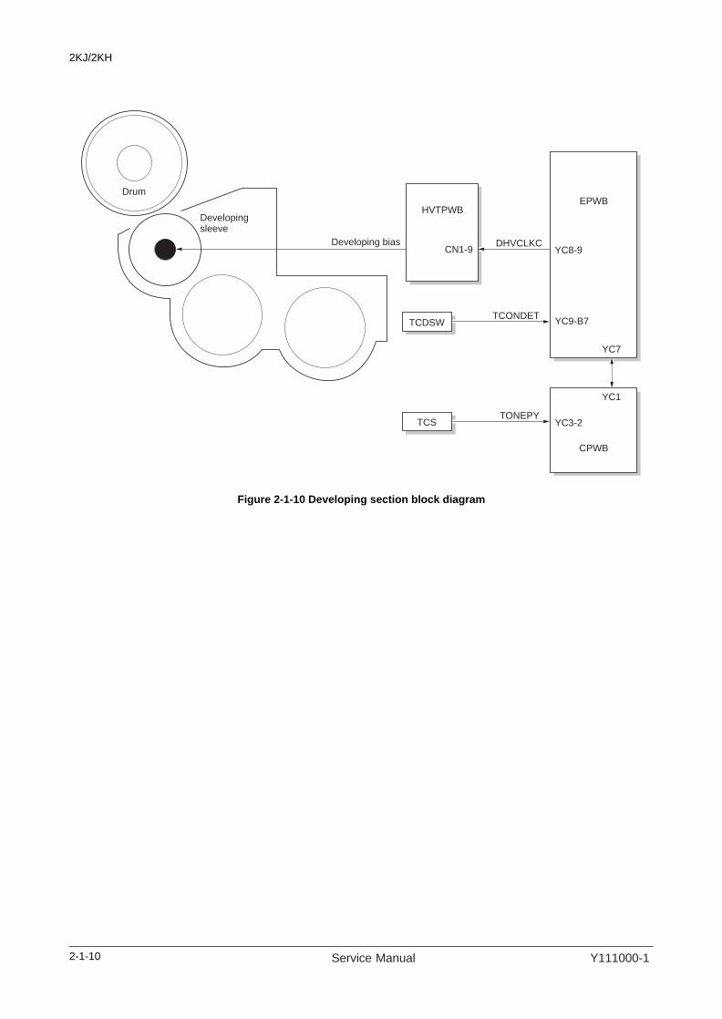
2KJ/2KH
Figure 2-1-10 Developing section block diagram
TCONDETYC9-B7
YC3-2
YC1
YC7
TCDSW
TONEPYTCS
HVTPWBEPWB
CPWB
CN1-9
Drum
Developingsleeve
DHVCLKCDeveloping biasYC8-9
2-1-10 Service Manual Y111000-1

2KJ/2KH
(1) Single component developing system
This machine uses the single component developing system, and reversal processing is performed with a + charged drumand a + charged magnetic toner.With the single component developing system, toner is electrically charged by friction with the developing sleeve and +charged when it passes through the magnetic toner blade. The toner that has passed through the magnetic toner bladeforms a uniform layer on the developing sleeve. When the toner layer comes to the location where the developing sleeveis the nearest to the drum, toner moves between the drum and the developing sleeve by an electric field of the magneticpole. Then, when the developing sleeve rotates and passes through the nearest location to the drum, on the portion of thedrum that has been exposed to light, toner is attracted toward the drum by potential difference between the developingbias and the drum surface and development is performed. On the other hand, on the portion of the drum that has not beenexposed to light, toner is attracted toward the sleeve and development is not performed. When toner comes to an areawhere the gap between the drum and the developing sleeve is large, an electric field disappears and toner does not leavethe developing sleeve. Development is complete.
Figure 2-1-11 Single component developing system
North pole
South pole
Developing sleeve
Drum
Magnetic toner blade
Toner
2-1-11Y111000-1 Service Manual

2KJ/2KH
2-1-5 Transfer and separation sectionsThe transfer and separation sections consists of the transfer roller, separation electrode and drum separation claws.A high voltage generated by the high voltage PWB (HVTPWB) is applied to the transfer roller for transfer charging.Paper after transfer is separated from the drum by applying separation bias that is output from the high voltage PWB(HVTPWB) to the separation electrode.
Figure 2-1-12 Transfer and separation sections
Figure 2-1-13 Transfer and separation sections block diagram
3
2
1
4
(1) Transfer roller(2) Separation electrode(3) Drum separation claw(4) Drum
Drum
Transfer roller
Separationelectrode
Separationhigh voltageSHVDRN
Transfehigh voltage
HVTPWB
CN1-6
SHVISELNCN1-8
THVADJCCN1-3
THVDRNCN1-4
EPWB
YC8-6
YC8-8
YC8-3
YC8-4
2-1-12 Service Manual Y111000-1

2KJ/2KH
2-1-6 Fuser sectionThe fuser section consists of the parts shown in figure. When paper reaches the fuser section after the transfer process itpasses between the press roller and heat roller, which is heated by fuser heaters M and S (FH-M/S). Pressure is appliedby the fuser unit pressure springs so that the toner on the paper is melted, fused and fixed onto the paper.The heat roller is heated by fuser heaters M and S (FH-M/S) inside it; its surface temperature is detected by the fuser ther-mistor (FTH) and is regulated by the fuser heaters turning on and off. If the fuser section becomes abnormally hot, fuserthermostat (FTS) operates shutting the power to the fuser heaters off.When the fuser process is completed, the paper is separated from the heat roller by its separation claws and is conveyedto eject and switchback section.
Figure 2-1-14 Fuser section
3
1
6
7
5
4
9, 10
8
2
(1) Left fuser unit(2) Right fuser unit(3) Press roller(4) Heat roller(5) Heat roller separation claws
(6) Fuser heater M (FH-M)(7) Fuser heater S (FH-S)(8) Fuser thermistor (FTH)(9) Fuser thermostat 1 (FTS1)(10) Fuser thermostat 2 (FTS2)
2-1-13Y111000-1 Service Manual

2KJ/2KH
Figure 2-1-15 Fuser section block diagram
FTS1
THERMA
Heat roller
FH-M
FH-S
SH
MH
LIV
E
FTS2
FTH
MHREM
SHREM
YC3-B9
EPWB
YC18-1
YC18-3PSPWB
YC
4-2
YC
4-1
YC
4-3
YC2-7
YC2-5
2-1-14 Service Manual Y111000-1
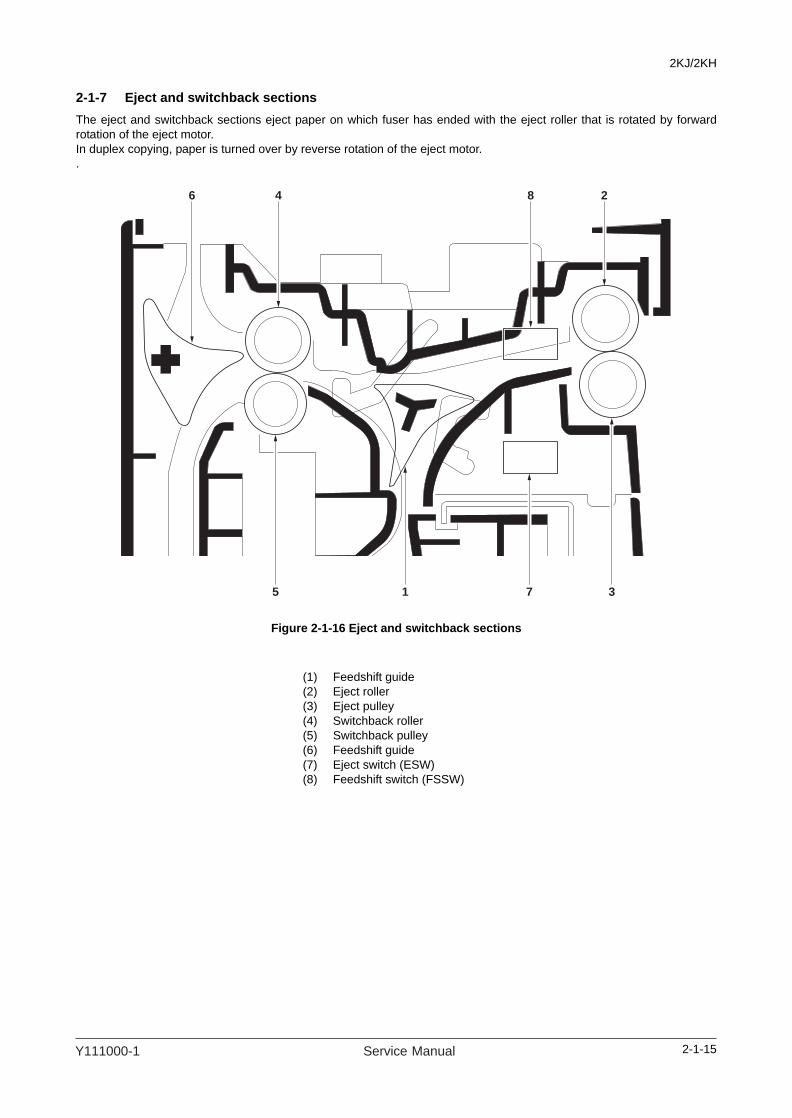
2KJ/2KH
2-1-7 Eject and switchback sectionsThe eject and switchback sections eject paper on which fuser has ended with the eject roller that is rotated by forwardrotation of the eject motor.In duplex copying, paper is turned over by reverse rotation of the eject motor..
Figure 2-1-16 Eject and switchback sections
5 1 7 3
846 2
(1) Feedshift guide(2) Eject roller(3) Eject pulley(4) Switchback roller(5) Switchback pulley(6) Feedshift guide(7) Eject switch (ESW)(8) Feedshift switch (FSSW)
2-1-15Y111000-1 Service Manual

2KJ/2KH
Figure 2-1-17 Eject and switchback sections block diagram
FSSWSEPSWN
YC14-3
EPWB
ESWEXTSWN
YC14-2
COMDB
COMDA
COMDNB
COMDNAYC13-2
YC13-1
YC13-4
YC13-3EM
2-1-16 Service Manual Y111000-1

2KJ/2KH
2-1-8 Duplex sectionIn duplex mode, after copying on to the reverse face of the paper, the paper is reversed in the switchback section and con-veyed to the duplex unit. The paper is then conveyed to the paper feed section by the upper and lower duplex feed rollers.
Figure 2-1-18 Duplex section
1
3
5
6
4
2
(1) Feedshift guide(2) Duplex feed pulley(3) Upper duplex feed roller(4) Duplex feed pulley(5) Lower duplex feed roller(6) Duplex paper conveying switch (DUPPCSW)
2-1-17Y111000-1 Service Manual

2KJ/2KH
Figure 2-1-19 Duplex section block diagram
CPWB
DUPPCSW
IPPSWNYC5-5
YC1
YC7
DUPFCLICLTN
YC5-8
EPWB
2-1-18 Service Manual Y111000-1

2KJ/2KH
2-2 Electrical Parts Layout
2-2-1 Electrical parts layout
(1) PWBs
Figure 2-2-1 PWBs
1. Engine PWB (EPWB)................................... Controls the other PWBs, electrical components and optional devices.2. Main PWB (MPWB) ..................................... Controls the operation panel and laser scanner unit.3. Power source PWB (PSPWB) ..................... Generates +24 V DC; controls the fuser heaters.4. High voltage PWB (HVTPWB) ..................... Main charging. Generates high voltages for transfer and high voltages for
separation.5. Inverter PWB (INPWB) ................................ Controls the exposure lamp.6. CCD PWB (CCDPWB)................................. Reads the image of originals.7. Operation unit PWB (OPWB)....................... Consists of the operation keys and display LEDs.8. LCD PWB (LCDPWB).................................. Controls LCD indication.9. APC PWB (APCPWB) ................................. Generates and controls the laser beam.10. PD PWB (PDPWB) ...................................... Controls horizontal synchronizing timing of laser beam.11. Cassette PWB (CPWB) ............................... Relays wirings from electrical components.12. Cassette main PWB (CMPWB)*1.................. Controls electrical components of the paper feeder.13. Cassette heater PWB (CHPWB)*1................ Relays the cassette heater power.14. Fax control PWB (FCPWB)*2........................ Modulates, demodulates, compresses, decompresses and smoothes out
image data, and converts resolution of image data.
Machine front Machine inside Machine rear
214
15
4
10
9
5
6
87
11
1213
1
316
2-2-1Y111000-1 Service Manual
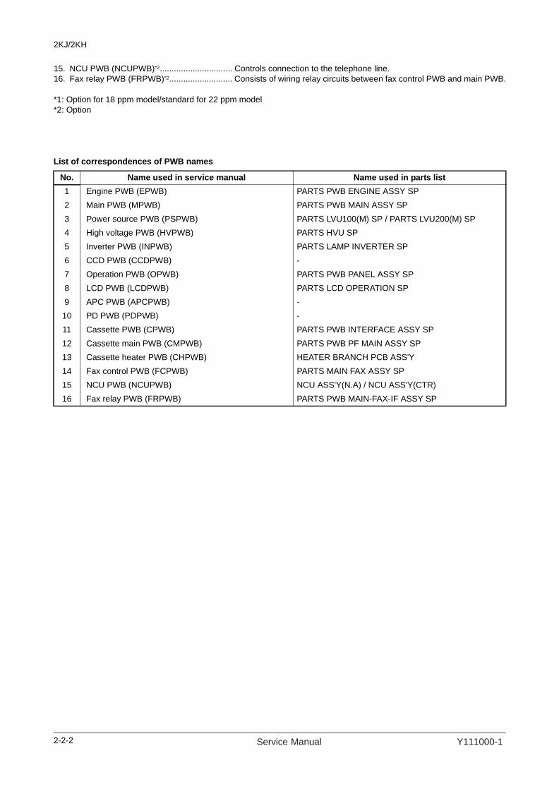
2KJ/2KH
15. NCU PWB (NCUPWB)*2............................... Controls connection to the telephone line.16. Fax relay PWB (FRPWB)*2........................... Consists of wiring relay circuits between fax control PWB and main PWB.
*1: Option for 18 ppm model/standard for 22 ppm model*2: Option
List of correspondences of PWB names
No. Name used in service manual Name used in parts list1 Engine PWB (EPWB) PARTS PWB ENGINE ASSY SP2 Main PWB (MPWB) PARTS PWB MAIN ASSY SP3 Power source PWB (PSPWB) PARTS LVU100(M) SP / PARTS LVU200(M) SP4 High voltage PWB (HVPWB) PARTS HVU SP5 Inverter PWB (INPWB) PARTS LAMP INVERTER SP6 CCD PWB (CCDPWB) -7 Operation PWB (OPWB) PARTS PWB PANEL ASSY SP8 LCD PWB (LCDPWB) PARTS LCD OPERATION SP9 APC PWB (APCPWB) -10 PD PWB (PDPWB) -11 Cassette PWB (CPWB) PARTS PWB INTERFACE ASSY SP12 Cassette main PWB (CMPWB) PARTS PWB PF MAIN ASSY SP13 Cassette heater PWB (CHPWB) HEATER BRANCH PCB ASS'Y14 Fax control PWB (FCPWB) PARTS MAIN FAX ASSY SP15 NCU PWB (NCUPWB) NCU ASS'Y(N.A) / NCU ASS'Y(CTR)16 Fax relay PWB (FRPWB) PARTS PWB MAIN-FAX-IF ASSY SP
2-2-2 Service Manual Y111000-1

2KJ/2KH
(2) Switches and sensors
Figure 2-2-2 Switches and sensors
1. Main power switch (MSW) ........................... Turns the AC power on and off.2. Front cover safety switch (FCSSW)............. Breaks the safety circuit when the front cover is opened.3. Left cover safety switch (LCSSW) ............... Breaks the safety circuit when the left cover is opened.4. Paper switch (PSW)..................................... Detects the presence of paper in the cassette.5. Paper size length switch (PLSW) ................ Detects the length of paper in the cassette.6. Paper size width switch (PWSW)................. Detects the width of paper in the cassette.7. MP paper size width switch (MPPWSW) ..... Detects the width of paper on the MP tray.8. Home position switch (HPSW)..................... Detects the optical system in the home position.9. Original detection switch (ODSW) ............... Operates the original size detection sensor.10. Original size detection sensor (OSDS) ........ Detects the size of the original.11. Registration switch (RSW) ........................... Controls the secondary paper feed start timing.12. Eject switch (ESW) ...................................... Detects a paper misfeed in the fuser section.13. Feedshift switch (FSSW) ............................. Detects a paper misfeed in the switchback section in a duplex copy.14. Toner container sensor (TCS)...................... Detects the quantity of toner in a toner container.15. Toner container detection switch
(TCDSW) ..................................................... Detects the presence of the toner container.16. Overflow sensor (OFS) ................................ Detects when the waste toner box is full.17. Fuser thermistor (FTH) ................................ Detects the heat roller temperature.
1
13
14
15
12
216
11
17
18
2021
2223
19
24
10
7
3
6
9
8
4
5
Machine front Machine inside Machine rear
2-2-3Y111000-1 Service Manual

2KJ/2KH
18. MP paper switch (MPPSW) ......................... Detects the presence of paper on the MP tray.19. Cassette left cover safety switch
(CLCSSW)*1 ................................................. Breaks the safety circuit when the cassette left cover is opened.20. Cassette feed switch (CFSW)*1.................... Detects a paper misfeed.21. Cassette paper switch (CPSW)*1 ................. Detects the presence of paper in the cassette.22. Cassette paper size length switch
(CPLSW)*1.................................................... Detects the length of paper in the cassette.23. Cassette paper size width switch
(CPWSW)*1 .................................................. Detects the width of paper in the cassette.24. Duplex paper conveying switch
(DUPPCSW)*2 .............................................. Detects a paper jam in the duplex section.
*1: Option for 18 ppm model/standard for 22 ppm model*2: Option
2-2-4 Service Manual Y111000-1
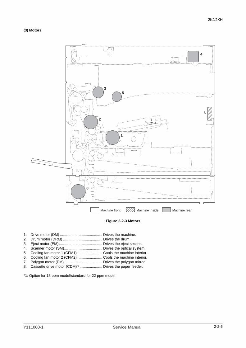
2KJ/2KH
(3) Motors
Figure 2-2-3 Motors
1. Drive motor (DM) ......................................... Drives the machine.2. Drum motor (DRM) ...................................... Drives the drum.3. Eject motor (EM) .......................................... Drives the eject section.4. Scanner motor (SM)..................................... Drives the optical system.5. Cooling fan motor 1 (CFM1) ........................ Cools the machine interior.6. Cooling fan motor 2 (CFM2) ........................ Cools the machine interior.7. Polygon motor (PM) ..................................... Drives the polygon mirror.8. Cassette drive motor (CDM)*1 ...................... Drives the paper feeder.
*1: Option for 18 ppm model/standard for 22 ppm model
2
4
1
8
3
7
5
6
Machine front Machine inside Machine rear
2-2-5Y111000-1 Service Manual

2KJ/2KH
(4) Others
Figure 2-2-4 Other electrical components
1. Paper feed clutch (PFCL) ............................ Primary paper feed from the cassette.2. Registration clutch (RCL)............................. Secondary paper feed.3. MP solenoid (MPSOL) ................................. Primary paper feed from the MP tray.4. Exposure lamp (EL) ..................................... Exposes originals.5. Cleaning lamp (CL) ...................................... Removes residual charge from the drum surface.6. Fuser heater M (FH-M) ................................ Heats the heat roller.7. Fuser heater S (FH-S) ................................. Heats the heat roller.8. Fuser thermostat 1 (FTS1)........................... Prevents overheating in the fuser section.9. Fuser thermostat 2 (FTS2)........................... Prevents overheating in the fuser section.10. Cassette heater (CH) ................................... Dehumidifies the cassette section.11. Cassette heater (CH)*1 ................................. Dehumidifies the cassette section.12. Cassette paper feed clutch (CPFCL)*1 ......... Primary paper feed from the cassette.13. Duplex feed clutch (DUPFCL)*2.................... Controls the drive of the duplex feed roller.
*1: Option for 18 ppm model/standard for 22 ppm model*2: Option
1
12
5
4
2
3
6
78, 9
10
11
13
Machine front Machine inside Machine rear
2-2-6 Service Manual Y111000-1

2KJ/2KH
2-3 Operation of the PWBs
2-3-1 Power source PWB
Figure 2-3-1 Power source PWB silk-screen diagram
YC4
YC2
YC1
YC3
TB1
TB3
TB4
TB2
2-3-1Y111000-1 Service Manual

2KJ/2KH
Connector Pin No. Signal I/O Voltage Description
TB 1 AC_LIVE I 120 V AC220-240 V AC
AC power input
Connected to the AC inlet and main power switch
2 AC_COM I 120 V AC220-240 V AC
AC power input
3 LIVE O 120 V AC220-240 V AC
AC power output to MSW
4 LIVE I 120 V AC220-240 V AC
AC power input from MSW
YC1 1 GND - - Ground
Connected to the engine PWB
2 +24V O 24 V DC 24 V DC power output to EPWB
3 +24V O 24 V DC 24 V DC power output to EPWB
4 +24V O 24 V DC 24 V DC power output to EPWB
5 GND - - Ground
6 GND - - Ground
YC2 1 +24V2 O 24 V DC 24 V DC power output to EPWB
Connected to the engine PWB
2 ZCROSS O 0/3.3 V DC (pulse) Zero-cross signal
3 RELAYREM I 0/3.3 V DC Relay signal
4 GND - - Ground
5 SHREM I 0/3.3 V DC FH-S: On/Off
6 SLEEP I 0/3.3 V DC Sleep signal: On/Off
7 MHREM I 0/3.3 V DC FH-M: On/Off
YC3 1 LIVE O 120 V AC220-240 V AC
AC power output to CH
Connected to the cas-sette heater and paper feeder
2 LIVE O 120 V AC220-240 V AC
AC power output to CH
3 NC - - Not used
4 NEUTRAL O 120 V AC220-240 V AC
AC power output to CH (paper feeder)
5 NEUTRAL O 120 V AC220-240 V AC
AC power output to CH (paper feeder)
YC4 1 MH O 120 V AC220-240 V AC
FH-M: On/Off
Connected to the fuser heater M/S
2 SH O 120 V AC220-240 V AC
FH-S: On/Off
3 LIVE O 120 V AC220-240 V AC
AC power output to FM-M/S
2-3-2 Service Manual Y111000-1

2KJ/2KH
2-3-2 Main PWB
Figure 2-3-2 Main PWB silk-screen diagram
U58 YC14
YC20
YC10
YC6 YC8 YC22
YC21
YS2
YC16
U57
U56
U55
U21
U18
U20U54
U52
U53
U74
U73
U72 U70 YC17
YS4
U65
U67 YC19
U75
YS3
YC
13
U71
U66
YC18
U85
U76 U81
YC1
U8
U59
U63 U64 U42
YC12
YC15 YC5
YC3
U29
U24
U41
U4
U22U27U6
U19
U23U1 U2
U38
U26U28
U32U34U36 U33
U31U51
U50
U7
U45
U61
U60
U62LED1
LED2U11
U3U46U48U47U49U68
U5
U43
YC7
U35U30
YC9
YC2
YS1
YC4
BAT1
U9
13
1
A29
7 1 10 11 1
2
1
20
2
A30B29B30
A1A2B1B2
15
1
1 161 111
B49B50A49A50
B1B2A1A2
160
3031
113
1
50
1
25
26
50
5 132 2
31 1
16
12
1
2
19
20
2-3-3Y111000-1 Service Manual

2KJ/2KH
Connector Pin No. Signal I/O Voltage DescriptionYC5 1 5V O 5 V DC 5 V DC power output to CCDPWB
Connected to the CCD PWB
2 NC - - Not used
3 TG O 0/3.3 V DC CCD control signal
4 GND - - Ground
5 RS I 0/3.3 V DC CCD control signal
6 GND - - Ground
7 CP O 0/3.3 V DC CCD control signal
8 GND - - Ground
9 PHY2 - 0/3.3 V DC (pulse) CCD clock signal
10 GND - - Ground
11 GND - - Ground
12 Vout1 Analog CCD output signal
13 Vout2 Analog CCD output signal
14 GND - - Ground
15 NC - - Not used
16 CCDPWR O 12 V DC 12 V DC power output to CCDPWB
YC6 1 PDN I 0/3.3 V DC Laser sync signal
Connected to the APC PWB
2 SGND - - Ground
3 OUTREN O 0/3.3 V DC Laser diode output signal
4 SAMPLEN O 0/3.3 V DC Sample hold signal
5 VDON O - Image data signal
6 VDOP O - Image data signal
7 5V1 O 5 V DC 5 V DC power output to APCPWB
YC7 1 _RST_ENG O 0/3.3 V DC EPWB reset signal
Connected to the engine PWB
2 SCANHLD O 0/3.3 V DC EPWB hold signal
3 ENGHLD O 0/3.3 V DC EPWB hold signal
4 AFEOVSYNC I 0/3.3 V DC (pulse) Image control signal
5 GND - - Ground
6 _24V_DOWN I 0/3.3 V DC EPWB 24 V down signal
7 PVSYNC I 0/3.3 V DC (pulse) Image control signal
8 GND - - Ground
9 EGOUTPEN I 0/3.3 V DC Laser diode output signal
10 PLGCLK O 0/3.3 V DC (pulse) PM clock signal
11 SLEEP O 0/3.3 V DC EPWB sleep signal
12 GND - - Ground
13 EGSIRN I 0/3.3 V DC EPWB interrupt signal
14 EGSDIR I 0/3.3 V DC EPWB communication direction signal
15 GND - - Ground
16 EGSBSY I 0/3.3 V DC EPWB busy siganal
17 EGSDO_BUF O 0/3.3 V DC (pulse) EPWB serial communication data signal
18 GND - - Ground
19 EGSCLK_BUF O 0/3.3 V DC (pulse) EPWB clock signal
20 EGSDI I 0/3.3 V DC (pulse) EPWB serial communication data signal
2-3-4 Service Manual Y111000-1

2KJ/2KH
YC8 1 +5V I 5 V DC 5 V DC power input from EPWB
Connected to the engine PWB
2 +5V I 5 V DC 5 V DC power input from EPWB
3 +5V I 5 V DC 5 V DC power input from EPWB
4 GND - - Ground
5 +3.3V I 3.3 V DC 3.3 V DC power input from EPWB
6 +3.3V I 3.3 V DC 3.3 V DC power input from EPWB
7 GND - - Ground
8 GND - - Ground
9 GND - - Ground
10 +5V I 5 V DC 5 V DC power input from EPWB
YC10 1 GND - - Ground
Connected to the fax control PWB (fax relay PWB)
2 5V O 5 V DC 5 V DC power output to FCPWB
3 CLKOUT O 0/3.3 V DC (pulse) FCPWB clock siganal
4 5V O 5 V DC 5 V DC power output to FCPWB
5 GND - - Ground
6 MREOUT O 0/3.3 V DC FCPWB control siganal
7 _HSYNCOUT O 0/3.3 V DC FCPWB control siganal
8 GND - - Ground
9 _VSYNCOUT O 0/3.3 V DC FCPWB control siganal
10 _IDOUT O 0/3.3 V DC FCPWB control siganal
11 GND - - Ground
12 GND - - Ground
13 TXD O 0/3.3 V DC (pulse) FCPWB transmission data signal
14 _STS O 0/3.3 V DC FCPWB control siganal
15 _MAIN_STS O 0/3.3 V DC FCPWB control siganal
16 FAXDOWN O 0/3.3 V DC FCPWB control siganal
17 MREIN I 0/3.3 V DC FCPWB control siganal
18 GND - - Ground
19 _VSYNCIN I 0/3.3 V DC FCPWB control siganal
20 CLKIN I 0/3.3 V DC (pulse) FCPWB clock siganal
21 GND - - Ground
22 GND - - Ground
23 _IDIN I 0/3.3 V DC FCPWB control siganal
24 _SET I 0/3.3 V DC FCPWB control siganal
25 _SREQ I 0/3.3 V DC FCPWB control siganal
26 _READY I 0/3.3 V DC FCPWB ready signal
27 RXD I 0/3.3 V DC (pulse) FCPWB received data signal
28 GND - - Ground
29 _RST O 0/3.3 V DC FCPWB reset signal
30 GND - - Ground
31 _W_UP I 0/3.3 V DC FCPWB control siganal
32 +24VSL O 24 V DC 24 V DC power output to FCPWB
Connector Pin No. Signal I/O Voltage Description
2-3-5Y111000-1 Service Manual

2KJ/2KH
YC14 1 +5V O 5 V DC 5 V DC power output to LCDPWB
Connected to the LCD PWB
2 -12V O 12 V DC 12 V DC power output to LCDPWB
3 LCDUD3 O 0/3.3 V DC (pulse) LCD indicator data signal 3
4 LCDUD2 O 0/3.3 V DC (pulse) LCD indicator data signal 2
5 LCDUD1 O 0/3.3 V DC (pulse) LCD indicator data signal 1
6 LCDUD0 O 0/3.3 V DC (pulse) LCD indicator data signal 0
7 LCDCP O 0/3.3 V DC LCD indicator control signal
8 LCDFLM O 0/3.3 V DC LCD indicator control signal
9 GND - - Ground
10 LCDENB O 0/3.3 V DC LCD indicator control signal
11 GND - - Ground
12 LCDLP O 0/3.3 V DC LCD indicator control signal
13 LCDV0 O 0/3.3 V DC LCD indicator control signal
YC15 1 SCAN7 O 0/3.3 V DC (pulse) Scan signal 7
Connected to the opera-tion PWB
2 SCAN6 O 0/3.3 V DC (pulse) Scan signal 6
3 SCAN5 O 0/3.3 V DC (pulse) Scan signal 5
4 SCAN4 O 0/3.3 V DC (pulse) Scan signal 4
5 SCAN3 O 0/3.3 V DC (pulse) Scan signal 3
6 SCAN2 O 0/3.3 V DC (pulse) Scan signal 2
7 SCAN1 O 0/3.3 V DC (pulse) Scan signal 1
8 SCAN0 O 0/3.3 V DC (pulse) Scan signal 0
9 +5V O 5 V DC 5 V DC power output to OPWB
10 BUZERDRN O 0/3.3 V DC OPWB buzzer signal
11 SGND - - Ground
YC16 1 KEY0 I 0/3.3 V DC (pulse) Operation panel key scan return signal 0
Connected to the opera-tion PWB
2 KEY1 I 0/3.3 V DC (pulse) Operation panel key scan return signal 1
3 KEY2 I 0/3.3 V DC (pulse) Operation panel key scan return signal 2
4 KEY3 I 0/3.3 V DC (pulse) Operation panel key scan return signal 3
5 KEY4 I 0/3.3 V DC (pulse) Operation panel key scan return signal 4
6 KEY5 I 0/3.3 V DC (pulse) Operation panel key scan return signal 5
7 KEY6 I 0/3.3 V DC (pulse) Operation panel key scan return signal 6
8 KEY7 I 0/3.3 V DC (pulse) Operation panel key scan return signal 7
9 KEY8 I 0/3.3 V DC (pulse) Operation panel key scan return signal 8
10 KEY9 I 0/3.3 V DC (pulse) Operation panel key scan return signal 9
11 LED4 O 0/3.3 V DC (pulse) Operation panel indicator LED drive signal 4
12 LED3 O 0/3.3 V DC (pulse) Operation panel indicator LED drive signal 3
13 LED2 O 0/3.3 V DC (pulse) Operation panel indicator LED drive signal 2
14 LED1 O 0/3.3 V DC (pulse) Operation panel indicator LED drive signal 1
15 LED0 O 0/3.3 V DC (pulse) Operation panel indicator LED drive signal 0
16 POWERKEY I 0/3.3 V DC Power key input
YC22 1 +24V I 24 V DC 24 V DC power input from PSPWB
Connected to the power source PWB
2 GND - - Ground
Connector Pin No. Signal I/O Voltage Description
2-3-6 Service Manual Y111000-1

2KJ/2KH
2-3-3 Engine PWB
Figure 2-3-3 Engine PWB silk-screen diagram
YC15 YC16 YC8
YC5 YC4
YC10
YC3
YC2
YC22
YC26
YC12
YC24
YC14
YC13
YC6
YC1
YC17
YC19YC23
U12
U5
U4
U13
U14
U2
U1
U10U3
U9
U11U8 U7
U6
YC25
YC9
YC7YC18
YC20
1
2
4
5
14
1
1
7
1
1
1
4
11
B1
A12
B12
A1
1
1
2
13
B1
B9
A9
A1
4
1
11
5
1920
21
8
1
1
A9A8
22271
231 B1B2
A1A2
B9B8
2
11
9
2
10
5
15
2
16
4
1
2
11
102
5
6
2-3-7Y111000-1 Service Manual

2KJ/2KH
Connector Pin No. Signal I/O Voltage DescriptionYC1 1 _RST_ENG I 0/3.3 V DC MPWB reset signal
Connected to the main PWB
2 SCANHLD I 0/3.3 V DC MPWB hold signal
3 ENGHLD I 0/3.3 V DC MPWB hold signal
4 AFEOVSYNC O 0/3.3 V DC (pulse) Image control signal
5 GND - - Ground
6 _24V_DOWN O 0/3.3 V DC MPWB 24V down signal
7 PVSYNC O 0/3.3 V DC (pulse) Image control signal
8 GND - - Ground
9 EGOUTPEN O 0/3.3 V DC Laser diode output signal
10 PLGCLK I 0/3.3 V DC (pulse) PM clock signal
11 SLEEP I 0/3.3 V DC MPWB sleep signal
12 GND - Analog Ground
13 EGSIRN O 0/3.3 V DC MPWB interrupt signal
14 EGSDIR o 0/3.3 V DC MPWB communication direction signal
15 GND - - Ground
16 EGSBSY O 0/3.3 V DC MPWB busy signal
17 EGSDO_BUF I 0/3.3 V DC (pulse) MPWB serial communication data signal
18 GND - - Ground
19 EGSCLK_BUF I 0/3.3 V DC (pulse) MPWB clock signal
20 EGSDI O 0/3.3 V DC (pulse) MPWB serial communication data signal
YC3 A1 PLGCLKN O 0/3.3 V DC (pulse) PM clock signal
Connected to the poly-gon motor, cooling fan motor 1, overflow sensor, cleaning lamp and fuser ther-mistor
A2 PLGRDYN I 0/3.3 V DC PM ready signal
A3 PLGDRN O 0/3.3 V DC PM: On/Off
A4 PLGGND - - Ground
A5 PLG+24V1 O 24 V DC 24 V DC power output to PM
A6 FAN1DRN O 0/24 V DC CFM1: On/Off
A7 FAN1+24V1 O 24 V DC 24 V DC power output to CFM1
A8 NC - - Not used
A9 NC - - Not used
B1 TONEGND - - Ground
B2 TONEFULL I 0/5 V DC OFS: On/Off
B3 TONE+5V2 O 5 V DC 5 V DC power output to OFS
B4 ERASE+24V1 O 24 V DC 24 V DC power output to CL
B5 NC - - Not used
B6 ERASE2N O 0/24 V DC CL: On/Off
B7 ERASE1N O 0/24 V DC CL: On/Off
B8 THERMAGND I - Ground
B9 THERMA - Analog FTH detection signal
2-3-8 Service Manual Y111000-1
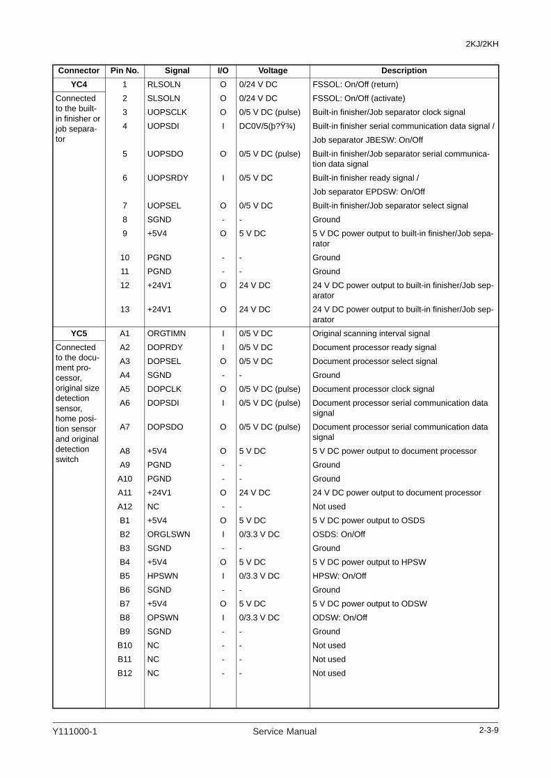
2KJ/2KH
YC4 1 RLSOLN O 0/24 V DC FSSOL: On/Off (return)
Connected to the built-in finisher or job separa-tor
2 SLSOLN O 0/24 V DC FSSOL: On/Off (activate)
3 UOPSCLK O 0/5 V DC (pulse) Built-in finisher/Job separator clock signal
4 UOPSDI I DC0V/5(þ?Ÿ¾) Built-in finisher serial communication data signal /
Job separator JBESW: On/Off
5 UOPSDO O 0/5 V DC (pulse) Built-in finisher/Job separator serial communica-tion data signal
6 UOPSRDY I 0/5 V DC Built-in finisher ready signal /
Job separator EPDSW: On/Off
7 UOPSEL O 0/5 V DC Built-in finisher/Job separator select signal
8 SGND - - Ground
9 +5V4 O 5 V DC 5 V DC power output to built-in finisher/Job sepa-rator
10 PGND - - Ground
11 PGND - - Ground
12 +24V1 O 24 V DC 24 V DC power output to built-in finisher/Job sep-arator
13 +24V1 O 24 V DC 24 V DC power output to built-in finisher/Job sep-arator
YC5 A1 ORGTIMN I 0/5 V DC Original scanning interval signal
Connected to the docu-ment pro-cessor, original size detection sensor, home posi-tion sensor and original detection switch
A2 DOPRDY I 0/5 V DC Document processor ready signal
A3 DOPSEL O 0/5 V DC Document processor select signal
A4 SGND - - Ground
A5 DOPCLK O 0/5 V DC (pulse) Document processor clock signal
A6 DOPSDI I 0/5 V DC (pulse) Document processor serial communication data signal
A7 DOPSDO O 0/5 V DC (pulse) Document processor serial communication data signal
A8 +5V4 O 5 V DC 5 V DC power output to document processor
A9 PGND - - Ground
A10 PGND - - Ground
A11 +24V1 O 24 V DC 24 V DC power output to document processor
A12 NC - - Not used
B1 +5V4 O 5 V DC 5 V DC power output to OSDS
B2 ORGLSWN I 0/3.3 V DC OSDS: On/Off
B3 SGND - - Ground
B4 +5V4 O 5 V DC 5 V DC power output to HPSW
B5 HPSWN I 0/3.3 V DC HPSW: On/Off
B6 SGND - - Ground
B7 +5V4 O 5 V DC 5 V DC power output to ODSW
B8 OPSWN I 0/3.3 V DC ODSW: On/Off
B9 SGND - - Ground
B10 NC - - Not used
B11 NC - - Not used
B12 NC - - Not used
Connector Pin No. Signal I/O Voltage Description
2-3-9Y111000-1 Service Manual

2KJ/2KH
YC6 1 +24V2 O - 24 V DC power output to DM
Connected to the drive motor and drum motor
2 PGND - - Ground
3 MDMREM O 0/24 V DC DM: On/Off
4 MDMCLK O 0/3.3 V DC (pulse) DM clock signal
5 3.3V O 3.3 V DC 3.3 V DC power output to DM
6 MDMRDY I 0/3.3 V DC DM ready signal
7 3.3V O 3.3 V DC 3.3 V DC power output to DM
8 NC - - Not used
9 +24V2 O 24 V DC 24 V DC power output to DRM
10 PGND - - Ground
11 DDMREM O 0/24 V DC DRM: On/Off
12 DDMCLK O 0/3.3 V DC (pulse) DRM clock signal
13 PGND - - Ground
14 DDMRDY I 0/3.3 V DC DRM ready signal
15 PGND - - Ground
16 NC - - Not used
YC7 1 TEMP I Analog HUMS detection signal
Connected to the cas-sette PWB
2 HMCLK1 O 0/3.3 V DC (pulse) HUMS clock signal
3 HMCLK2 O 0/3.3 V DC (pulse) HUMS clock signal
4 HUMID I Analog HUMS detection signal
5 C1PWSWN I 0/3.3 V DC PWSW: On/Off
6 C1PDSWN I 0/3.3 V DC PSW: On/Off
7 +5V2 O 5 V DC 5 V DC power output to CPWB
8 TONEPY I Analog TCS detection signal
9 SGND - - Ground
10 BPWSW I 0/3.3 V DC MPPWSW: On/Off
11 REGSWN I 0/3.3 V DC RSW: On/Off
12 ICLTN O 0/24 V DC DUPFCL: On/Off
13 IPPSWN I 0/3.3 V DC DUPPCSW: On/Off
14 BPPESW I 0/3.3 V DC MPPSW: On/Off
15 SGND - - Ground
16 BSOLN O 0/24 V DC MPSOL: On/Off
17 FCLTN O 0/24 V DC PFCL: On/Off
18 REGCLN O 0/24 V DC RCL: On/Off
19 +24V1 O 24 V DC 24 V DC power output to CPWB
20 +24V1 O 24 V DC 24 V DC power output to CPWB
23 +3.3V O 3.3 V DC 3.3 V DC power output to CPWB
Connector Pin No. Signal I/O Voltage Description
2-3-10 Service Manual Y111000-1

2KJ/2KH
YC8 1 +24V2 O 24 V DC 24 V DC power output to HVTPWB
Connected to the high voltage PWB
2 +24V2 O 24 V DC 24 V DC power output to HVTPWB
3 THVADJC O Analog Transfer high voltage control signal
4 THVDRN O 0/3.3 V DC Transfer high voltage: On/Off
5 MHVADJC O Analog Main charger high voltage control signal
6 SHVDRN O 0/3.3 V DC Separation high voltage: On/Off
7 MHVDRN O 0/3.3 V DC Main charger high voltage: On/Off
8 SHVISELN O 0/3.3 V DC Separation high voltage switching signal
9 DHVCLKC O 0/3.3 V DC (pulse) Developing bias clock signal
10 PGND - - Ground
11 PGND - - Ground
YC9 A1 LOPSRDY I 0/5 V DC Paper feeder ready signal
Connected to the paper feeder, paper size length switch and toner con-tainer detec-tion switch
A2 LOPSEL2 O 0/5 V DC Paper feeder select signal 2
A3 LOPSEL1 O 0/5 V DC Paper feeder select signal 1
A4 LOPSEL0 O 0/5 V DC Paper feeder select signal 0
A5 LOPSCLK O 0/5 V DC (pulse) Paper feeder clock signal
A6 LOPSDI I 0/5 V DC (pulse) Paper feeder serial communication data signal
A7 LOPSDO O 0/5 V DC (pulse) Paper feeder serial communication data signal
A8 SGND - - Ground
A9 +5V2PF O 5 V DC 5 V DC power output to paper feeder
B1 SGND - - Ground
B2 +5V2PF O 5 V DC 5 V DC power output to paper feeder
B3 C1PLSW3N I 0/3.3 V DC PLSW: On/Off
B4 C1PLSW2N I 0/3.3 V DC PLSW: On/Off
B5 SGND - - Ground
B6 C1PLSW1N I 0/3.3 V DC PLSW: On/Off
B7 TCONDET I 0/3.3 V DC TCDSW: On/Off
B8 SGND - - Ground
B9 NC - - Not used
YC10 1 FAN2+24V1 O 24 V DC 24 V DC power output to CFM2
Connected to the cool-ing fan motor 2
2 FAN2DRN O 0/24 V DC CFM2: On/Off
YC12 1 +24V1 O 24 V DC 24 V DC power output to key counter
Connected to the key counter
2 KEYCN O 0/3.3 V DC Key counter signal
3 SGND - - Ground
4 KEYENBN I 0/3.3 V DC Key counter detection signal
YC13 1 COMDA O 0/24 V DC (pulse) EM drive control signal
Connected to the eject motor
2 COMDB O 0/24 V DC (pulse) EM drive control signal
3 COMDNA O 0/24 V DC (pulse) EM drive control signal
4 COMDNB O 0/24 V DC (pulse) EM drive control signal
Connector Pin No. Signal I/O Voltage Description
2-3-11Y111000-1 Service Manual
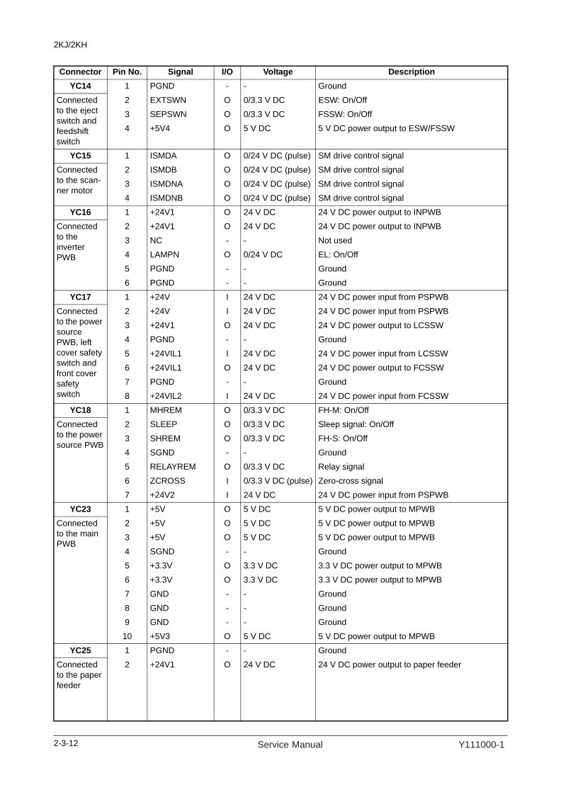
2KJ/2KH
YC14 1 PGND - - Ground
Connected to the eject switch and feedshift switch
2 EXTSWN O 0/3.3 V DC ESW: On/Off
3 SEPSWN O 0/3.3 V DC FSSW: On/Off
4 +5V4 O 5 V DC 5 V DC power output to ESW/FSSW
YC15 1 ISMDA O 0/24 V DC (pulse) SM drive control signal
Connected to the scan-ner motor
2 ISMDB O 0/24 V DC (pulse) SM drive control signal
3 ISMDNA O 0/24 V DC (pulse) SM drive control signal
4 ISMDNB O 0/24 V DC (pulse) SM drive control signal
YC16 1 +24V1 O 24 V DC 24 V DC power output to INPWB
Connected to the inverter PWB
2 +24V1 O 24 V DC 24 V DC power output to INPWB
3 NC - - Not used
4 LAMPN O 0/24 V DC EL: On/Off
5 PGND - - Ground
6 PGND - - Ground
YC17 1 +24V I 24 V DC 24 V DC power input from PSPWB
Connected to the power source PWB, left cover safety switch and front cover safety switch
2 +24V I 24 V DC 24 V DC power input from PSPWB
3 +24V1 O 24 V DC 24 V DC power output to LCSSW
4 PGND - - Ground
5 +24VIL1 I 24 V DC 24 V DC power input from LCSSW
6 +24VIL1 O 24 V DC 24 V DC power output to FCSSW
7 PGND - - Ground
8 +24VIL2 I 24 V DC 24 V DC power input from FCSSW
YC18 1 MHREM O 0/3.3 V DC FH-M: On/Off
Connected to the power source PWB
2 SLEEP O 0/3.3 V DC Sleep signal: On/Off
3 SHREM O 0/3.3 V DC FH-S: On/Off
4 SGND - - Ground
5 RELAYREM O 0/3.3 V DC Relay signal
6 ZCROSS I 0/3.3 V DC (pulse) Zero-cross signal
7 +24V2 I 24 V DC 24 V DC power input from PSPWB
YC23 1 +5V O 5 V DC 5 V DC power output to MPWB
Connected to the main PWB
2 +5V O 5 V DC 5 V DC power output to MPWB
3 +5V O 5 V DC 5 V DC power output to MPWB
4 SGND - - Ground
5 +3.3V O 3.3 V DC 3.3 V DC power output to MPWB
6 +3.3V O 3.3 V DC 3.3 V DC power output to MPWB
7 GND - - Ground
8 GND - - Ground
9 GND - - Ground
10 +5V3 O 5 V DC 5 V DC power output to MPWB
YC25 1 PGND - - Ground
Connected to the paper feeder
2 +24V1 O 24 V DC 24 V DC power output to paper feeder
Connector Pin No. Signal I/O Voltage Description
2-3-12 Service Manual Y111000-1

2KJ/2KH
2-3-4 Cassette PWB
Figure 2-3-4 Cassette PWB silk-screen diagram
YC1
TH2
TH1
YC4
YC3
YC2
YC5
YC6 YC7 YC8
SW1
1 234 1
1
3
3 1
1
2 12 1 12
13
2-3-13Y111000-1 Service Manual

2KJ/2KH
Connector Pin No. Signal I/O Voltage DescriptionYC1 1 TEMP O Analog HUMS detection signal
Connected to the engine PWB
2 HMCLK1 I 0/3.3 V DC (pulse) Not used
3 HMCLK2 I 0/3.3 V DC (pulse) HUMS clock signal
4 HUMID O Analog HUMS detection signal
5 C1PWSWN O 0/3.3 V DC PWSW: On/Off
6 C1PDSWN O 0/3.3 V DC PSW: On/Off
7 +5V2 I 5 V DC 5 V DC power input from EPWB
8 TONEPY O Analog TCS detection signal
9 SGND - - Ground
10 BPWSW O 0/3.3 V DC MPPWSW: On/Off
11 REGSWN O 0/3.3 V DC RSW: On/Off
12 ICLTN I Analog DUPFCL: On/Off
13 IPPSWN O 0/3.3 V DC DUPPCSW: On/Off
14 BPPESW O 0/3.3 V DC MPPSW: On/Off
15 SGND - - Ground
16 BSOLN I 0/24 V DC MPSOL: On/Off
17 FCLTN I 0/24 V DC PFCL: On/Off
18 REGCLN I 0/24 V DC RCL: On/Off
19 +24V1 I 24 V DC 24 V DC power input from EPWB
20 +24V1 I 24 V DC 24 V DC power input from EPWB
23 +3.3V I 3.3 V DC 3.3 V DC power input from EPWB
YC2 1 SGND - - Ground
Connected to the paper switch
2 C1PDSWN I 0/3.3 V DC PSW: On/Off
3 +5V2 O 5 V DC 5 V DC power output to PSW
YC3 1 +5V2 O 5 V DC 5 V DC power output to TCS
Connected to the toner container sensor
2 TONEPY I Analog TCS detection signal
3 SGND - - Ground
YC5 1 +5V2 O 5 V DC 5 V DC power output to MPPSW
Connected to the MP paper switch, duplex paper con-veying switch, duplex feed clutch, regis-tration switch and MP paper size width switch
2 BPPESW I 0/3.3 V DC MPPSW: On/Off
3 SGND - - Ground
4 +5V2 O 5 V DC 5 V DC power output to MPPCSW
5 IPPSWN I 0/3.3 V DC DUPPCSW: On/Off
6 SGND - - Ground
7 +24V1 O 24 V DC 24 V DC power output to DUPFCL
8 ICLTN O 0/24 V DC DUPFCL: On/Off
9 +5V2 O 5 V DC 5 V DC power output to RSW
10 REGSW I 0/3.3 V DC RSW: On/Off
11 SGND - - Ground
12 BPWSW I 0/3.3 V DC MPPWSW: On/Off
13 +3.3V O 3.3 V DC 3.3 V DC power output to MPPWSW
2-3-14 Service Manual Y111000-1

2KJ/2KH
YC6 1 +24V1 O 24 V DC 24 V DC power output to RCL
Connected to the regis-tration clutch
2 REGCLN O 0/24 V DC RCL: On/Off
YC7 1 +24V1 O 24 V DC 24 V DC power output to PFCL
Connected to the paper feed clutch
2 FCLTN O 0/24 V DC PFCL: On/Off
YC8 1 BSOLN O 0/24 V DC MPSOL: On/Off
Connected to the MP solenoid
2 +24V1 O 24 V DC 24 V DC power output to MPSOL
Connector Pin No. Signal I/O Voltage Description
2-3-15Y111000-1 Service Manual

2KJ/2KH
2-3-5 Operation PWB
Figure 2-3-5 Operation PWB silk-screen diagram
SW
68
SW
52
SW
51
SW
50
SW
61
SW
62
SW
63
SW
64
SW
57
SW
58
SW
59
SW
60
SW
53
SW
54
SW
45
SW
49
SW
44
SW
43
SW
48
SW
47
SW
42
SW
41
SW
46
SW
40
SW
39
SW
38
SW
36
SW
37
SW
34
SW
33
SW
32
SW
30
SW
31
SW
35
SW
29
SW
28
SW
27
SW
25
SW
26
SW
24
SW
23
SW
22
SW
21
SW
19
SW
20
SW
18
SW
17
SW
16
SW
15
SW
13
SW
14
SW
12
SW
69
SW
11
SW
5
SW
4
SW
3
SW
2
SW
1
SW
10
SW
9
SW
7
SW
8
SW
6
SW
55
SW
56
SW
65
SW
66
SW
67
DL
39
DL
38
DL
37
DL
36
DL
30
DL
31
DL
32
DL
33
DL
34
DL
35
DL
29
DL
27
DL
25
DL
28
DL
26
DL
24
DL
22
DL
20
DL
21
DL
18
DL
17
DL
16
DL
15
DL
10
DL
11
DL
12
DL
13
DL
6
DL
1
DL
2
DL
3
DL
4
DL
5
DL
7
DL
8
DL
9
DL
14
YC
1
BZ
1
111
DL
19
DL
23
YC
21
16
DL
40
2-3-16 Service Manual Y111000-1

2KJ/2KH
Connector Pin No. Signal I/O Voltage DescriptionYC1 1 SCAN7 I 0/3.3 V DC (pulse) Scan signal 7
Connected to the main PWB
2 SCAN6 I 0/3.3 V DC (pulse) Scan signal 6
3 SCAN5 I 0/3.3 V DC (pulse) Scan signal 5
4 SCAN4 I 0/3.3 V DC (pulse) Scan signal 4
5 SCAN3 I 0/3.3 V DC (pulse) Scan signal 3
6 SCAN2 I 0/3.3 V DC (pulse) Scan signal 2
7 SCAN1 I 0/3.3 V DC (pulse) Scan signal 1
8 SCAN0 I 0/3.3 V DC (pulse) Scan signal 0
9 +5V I 5 V DC 5 V DC power input from MPWB
10 BUZERDRN I 0/3.3 V DC OPWB buzzer signal
11 SGND - - Ground
YC2 1 POWERKEY O Analog Power key output
Connected to the main PWB
2 LED0 I 0/3.3 V DC (pulse) Operation panel indicator LED drive signal 0
3 LED1 I 0/3.3 V DC (pulse) Operation panel indicator LED drive signal 1
4 LED2 I 0/3.3 V DC (pulse) Operation panel indicator LED drive signal 2
5 LED3 I 0/3.3 V DC (pulse) Operation panel indicator LED drive signal 3
6 LED4 I 0/3.3 V DC (pulse) Operation panel indicator LED drive signal 4
7 KEY9 O 0/3.3 V DC (pulse) Operation panel key scan return signal 9
8 KEY8 O 0/3.3 V DC (pulse) Operation panel key scan return signal 8
9 KEY7 O 0/3.3 V DC (pulse) Operation panel key scan return signal 7
10 KEY6 O 0/3.3 V DC (pulse) Operation panel key scan return signal 6
11 KEY5 O 0/3.3 V DC (pulse) Operation panel key scan return signal 5
12 KEY4 O 0/3.3 V DC (pulse) Operation panel key scan return signal 4
13 KEY3 O 0/3.3 V DC (pulse) Operation panel key scan return signal 3
14 KEY2 O 0/3.3 V DC (pulse) Operation panel key scan return signal 2
15 KEY1 O 0/3.3 V DC (pulse) Operation panel key scan return signal 1
16 KEY0 O 0/3.3 V DC (pulse) Operation panel key scan return signal 0
2-3-17Y111000-1 Service Manual

2KJ/2KH
2-3-6 Cassette main PWB (22 ppm model only)
Figure 2-3-6 Cassette main PWB silk-screen diagram
YC2
YC1
YC3
YC7
U2
YC9
YC8
YC4YC5
SW1
YC6
1
1
A1
1
1
1
1
11
2
3
48
3
2
57
A13
B13B1
2
2
2-3-18 Service Manual Y111000-1

2KJ/2KH
Connector Pin No. Signal I/O Voltage DescriptionYC1 1 24V O 24 V DC 24 V DC power output to paper feeder
Connected to the paper feeder
2 PGND - - Ground
YC2 1 +24V1 I 24 V DC 24 V DC power input from EPWB
Connected to the engine PWB
2 PGND - - Ground
YC3 A1 5V - - Not used
Connected to the engine PWB and paper feeder
A2 SGND - - Not used
A3 5V I 5 V DC 5 V DC power input from EPWB
A4 SGND - - Ground
A5 5V I 5 V DC 5 V DC power input from EPWB
A6 SGND - - Ground
A7 SDI I 0/5 V DC (pulse) Paper feeder serial communication data signal
A8 SDO O Analog Paper feeder serial communication data signal
A9 SCLK I 0/5 V DC (pulse) Paper feeder clock signal
A10 SEL0 I 0/5 V DC Paper feeder select signal 0
A11 SEL1 I 0/5 V DC Paper feeder select signal 1
A12 SEL2 I 0/5 V DC Paper feeder select signal 2
A13 RDY O 0/5 V DC Paper feeder ready signal
B1 RDY I 0/5 V DC Paper feeder ready signal
B2 SEL2 O 0/5 V DC Paper feeder select signal 2
B3 SEL1 O 0/5 V DC Paper feeder select signal 1
B4 SEL0 O 0/5 V DC Paper feeder select signal 0
B5 SCLK O 0/5 V DC (pulse) Paper feeder clock signal
B6 SDO I 0/5 V DC (pulse) Paper feeder serial communication data signal
B7 SDI O 0/5 V DC (pulse) Paper feeder serial communication data signal
B8 SGND - - Ground
B9 5V O 5 V DC 5 V DC power output to paper feeder
B10 SGND - - Ground
B11 5V O 5 V DC 5 V DC power output to paper feeder
B12 SGND - - Not used
B13 5V - - Not used
YC4 1 SGND - - Ground
Connected to the cas-sette left cover safety switch, cas-sette paper size width switch and cassette paper size length switch
2 COVOPN O 0/24 V DC CLCSSW: On/Off
3 SGND - - Ground
4 SIZEA I 0/5 V DC CPWSW: On/Off
5 SIZEB I 0/5 V DC CPLSW: On/Off
6 SIZEC I 0/5 V DC CPLSW: On/Off
7 SGND - - Ground
8 SIZED I 0/5 V DC CPLSW: On/Off
2-3-19Y111000-1 Service Manual

2KJ/2KH
YC5 1 SGND - - Ground
Connected to the cas-sette paper switch
2 PE I 0/5 V DC CPSW: On/Off
3 5V O 5 V DC 5 V DC power output to CPSW
4 NC - - Not used
YC6 1 SGND - - Ground
Connected to the cas-sette feed switch
2 FEED I 0/5 V DC CFSW: On/Off
3 5V O 5 V DC 5 V DC power output to CFSW
YC8 1 24V O 24 V DC 24 V DC power output to CPFCL
Connected to the cas-sette paper feed clutch
2 CLT_RE O 0/24 V DC CPFCL: On/Off
YC9 1 24V O 24 V DC 24 V DC power output to CDM
Connected to the cas-sette drive motor
2 MOTA O 0/24 V DC (pulse) CDM drive control signal
3 MOTB O 0/24 V DC (pulse) CDM drive control signal
4 MOTA- O 0/24 V DC (pulse) CDM drive control signal
5 MOTB- O 0/24 V DC (pulse) CDM drive control signal
Connector Pin No. Signal I/O Voltage Description
2-3-20 Service Manual Y111000-1

2KJ/2KH
2-4 Appendixes
Maintenance parts list
Maintenance part name Part No. Alterna-tive part
Fig. No.
Ref. No.Name used in service manual Name used in parts list
Paper feed pulley PULLEY, PAPER FEED 906081L
Separation pulley PULLEY, SEPARATION 906082M
Forwarding pulley PULLEY, LEADING FEED 906175W
Cassette paper feed pulley PULLEY, PAPER FEED 906081L
Cassette separation pulley PULLEY, SEPARATION 906082M
Cassette forwarding pulley PULLEY, LEADING FEED 906175W
MP paper feed pulley PULLEY BYPASS AVGR11450N
MP separation pad PARTS BYPASS PAD ASSY SP AVGR11449Q
Left registration roller PARTS ROLLER REGIST LEFT SP AVGR11495U
Right registration roller RIGHT ROLL REGIST AVGR11496G
Feed roller ROLLER FEED T.B.D.
Feed pulley PULLEY FEED -
Slit glass CONTACT GLASS ADF AVGR00569W
Contact glass CONTACT GLASS AVGR08418S
Mirror 1 MIRROR A AVGR11497C
Mirror 2 and mirror 3 MIRROR B AVGR11498Z
Lens LENS -
Reflector REFLECTOR SCANNER NO CODE
Exposure lamp PARTS LAMP SCANNER SP AVGR11447X
Optical rail RAIL SCANNER -
Original size detection sensor SENSOR ORIGINAL AVGR00294W
Laser scanner unit LK-460 AVGR11451P
Transfer roller ROLLER TRANSFER AVGR05407K
Separation electrode PLATE STA ELIMINATION AVGR00513F
Developing unit DV-460 AVGR11453X
Main charger unit MC-460 AVGR11452T
Fuser unit
FK-460 AVGR11454L
Heat roller PARTS ROLLER HEAT SP AVGR11455Q
Press roller PARTS ROLLER PRESS SP AVGR11458M
Heat roller separation claw SEPARATOR ASSY AVGR00247V
Eject roller PARTS ROLLER EXIT INNER SP AVGR11499V
Eject pulley PULLEY EXIT AVGR11500X
Switchback roller PARTS ROLLER FEED SHIFT SP AVGR11501Y
Switchback pulley PULLEY FEED SHIFT AVGR00550S
2-4-1Y111000-1 Service Manual

2KJ/2KH
Periodic maintenance proceduresSection Maintenance
part/locationMethod Maintenance
cyclePoints and cautions Page
Test copy and test print
Perform at the maxi-mum copy size
Test copy Every service
Section Maintenancepart/location
Method Maintenance cycle
Points and cautions Page
Paper feed section
Paper feed pulley Check or replace
User call Clean it with alcohol if it is dirty.Replace it if any problem such as flawed or worn state is found.
P.1-5-6
Separation pulley Check or replace
User call Clean it with alcohol if it is dirty.Replace it if any problem such as flawed or worn state is found.
P.1-5-3
Forwarding pulley Check or replace
User call Clean it with alcohol if it is dirty.Replace it if any problem such as flawed or worn state is found.
P.1-5-6
Cassette paper feed pulley
Check or replace
User call Clean it with alcohol if it is dirty.Replace it if any problem such as flawed or worn state is found.
P.1-5-13
Cassette separation pulley
Check or replace
User call Clean it with alcohol if it is dirty.Replace it if any problem such as flawed or worn state is found.
P.1-5-11
Cassette forwarding pulley
Check or replace
User call Clean it with alcohol if it is dirty.Replace it if any problem such as flawed or worn state is found.
P.1-5-13
MP paper feed pulley Check, replace or clean
Every service Clean it with alcohol if it is dirty.Replace it if any problem such as flawed or worn state is found.
P.1-5-18
MP separation pad Check or replace
User call Clean it with alcohol if it is dirty.Replace it if any problem such as flawed or worn state is found.
P.1-5-18
Left registration roller Check, replace or clean
Every service Clean with alcohol or a dry cloth.Replace it if any problem such as flawed or worn state is found.
P.1-5-21
Right registration roller Check, replace or clean
Every service Clean with alcohol or a dry cloth. P.1-5-22
Feed roller Check or replace
User call Clean with alcohol or a dry cloth.Replace it if any problem such as flawed or worn state is found.
P.1-5-9
Feed pulley Check or clean
User call Clean with alcohol or a dry cloth.
2-4-2 Service Manual Y111000-1

2KJ/2KH
Section Maintenancepart/location
Method Maintenance cycle
Points and cautions Page
Opticalsection
Slit glass Clean Every service Clean with a dry cloth (do not clean with a wet cloth or alcohol).
Contact glass Clean Every service Clean with alcohol and then a dry cloth.
Mirror 1 Clean User call Clean with a wet cloth and then a dry cloth only if vertical black lines appear on the print image.
Mirror 2 and mirror 3 Clean User call Clean with a wet cloth and then a dry cloth only if vertical black lines appear on the print image.
Lens Clean User call Clean with a dry cloth only if verti-cal black lines appear on the print image.
Reflector Clean User call Clean with a dry cloth only if verti-cal black lines appear on the print image.
Exposure lamp Check or replace
User call Replace if an image problem occurs or after the exposure lamp does not turn on.
P.1-5-24
Optical rail Check or grease
User call Check noise and shifting and then apply optical rail grease EM-50LP.
Original size detection sensor
Check or clean
User call Clean the sensor emitter and sen-sor receiver with alcohol or a dry cloth only if there is a problem.
Laser scanner unit Check or clean
User call Clean the slit glass with alcohol and then a dry cloth.
P.1-5-35
Section Maintenancepart/location
Method Maintenance cycle
Points and cautions Page
Transfer/separationsection
Transfer roller Clean User call Vacuum or clean with a dry cloth when user call occurs.
P.1-5-45
Separation electrode Check or clean
User call Clean with a cleaning brush.
Section Maintenancepart/location
Method Maintenance cycle
Points and cautions Page
Developing section
Developing unit Check or replace
User call Replace if the problem occurs. P.1-5-44
Section Maintenancepart/location
Method Maintenance cycle
Points and cautions Page
Drum section Main charger unit Check or replace
Every service Replace if an image problem occurs.
P.1-5-43
2-4-3Y111000-1 Service Manual

2KJ/2KH
Section Maintenancepart/location
Method Maintenance cycle
Points and cautions Page
Fusersection
Fuser unit Check or replace
User call Replace if the problem occurs. P.1-5-47
Heat roller Clean 150K Clean with alcohol or a dry cloth. P.1-5-55
Press roller Clean 150K Clean with alcohol or a dry cloth. P.1-5-49
Heat roller separation claw
Check, replace or clean
Every service Clean with alcohol.Replace if claw is flawed, deformed or worn.
P.1-5-54
Section Maintenancepart/location
Method Maintenance cycle
Points and cautions Page
Eject section Eject roller Check or clean
User call Clean it with alcohol if it is dirty.
Eject pulley Check or clean
User call Clean it with alcohol if it is dirty.
Switchback roller Check or clean
User call Clean it with alcohol if it is dirty.
Switchback pulley Check or clean
User call Clean it with alcohol if it is dirty.
Section Maintenancepart/location
Method Maintenance cycle
Points and cautions Page
Covers Covers Clean Every service Clean with alcohol or a dry cloth.
Original cover Clean Every service Clean with alcohol or a dry cloth.
Section Maintenancepart/location
Method Maintenance cycle
Points and cautions Page
Other Image quality Check and adjust
Every service
2-4-4 Service Manual Y111000-1

2KJ/2KH
2-4-5
Page Remarks
P.1-3-16
P.1-3-16
P.1-3-13
P.1-3-13 First paper feeder: select LSU T1Second paper feeder: select LSU T2Third paper feeder: select LSU T3Duplex copying: select LSU DUP
P.1-3-12
P.1-3-12 First paper feeder: select RCL T1Second paper feeder: select RCL T2Third paper feeder: select RCL T3Duplex copying: select RCL DUP
P.1-3-53
P.1-3-53
P.1-3-53
P.1-3-18 No adjustment for copying using the DP.
Chart of image adjustment procedures
Adjusting order Item Image Description
Maintenance modeOriginal
Item No. Mode
1
Adjusting the magnification in the main scanning direction (printing adjustment)
Polygon motor speed adjustment U053 POLY U053 test pattern
2
Adjusting the magnification in the auxiliary scanning direction (print-ing adjustment)
Drive motor speed adjustment U053 MAIN U053 test pattern
3
Adjusting the center line of the MP tray (printing adjustment)
Adjusting the LSU print start timing U034 LSU BYP U034 test pattern
4
Adjusting the center line of the cas-settes (printing adjustment)
Adjusting the LSU print start timing U034 LSU OUT U034 test pattern
5
Adjusting the leading edge registra-tion of the MP tray (printing adjust-ment)
Registration clutch turning on timing (secondary paper feed start timing)
U034 RCL BYP U034 test pattern
6
Adjusting the leading edge registra-tion of the cassettes (printing adjustment)
Registration clutch turning on timing (secondary paper feed start timing)
U034 RCL ON U034 test pattern
7
Adjusting the leading edge margin (printing adjustment)
LSU illumination start timing U402 LESD U402 test pattern
8
Adjusting the trailing edge margin (printing adjustment)
LSU illumination end timing U402 TRAIL U402 test pattern
9
Adjusting the left and right margins (printing adjustment)
LSU illumination start/end timing U402 AC U402 test pattern
10
Adjusting magnification of the scanner in the main scanning direc-tion (scanning adjustment)
Data processing U065 MAIN SCAN ADJ Test chart

2KJ/2KH
2-4-6
When maintenance item U092 (Adjusting the scanner automatically) is run using the specified original (P/N AVGR05131K), the following adjustments are automatically made: Adjusting the scanner magnification (U065)Adjusting the scanner leading edge registration (U066)Adjusting the scanner center line (U067)
When maintenance item U076 (Adjusting the DP automatically) is run using the specified original (P/N AVGR11211F), the following adjustments are automatically made: Adjusting the DP magnification (U070) Adjusting the DP scanning timing (U071) Adjusting the DP center line (U072)
11
Adjusting magnification of the scanner in the auxiliary scanning direction (scanning adjustment)
Original scanning speed U065
U070
SUB SCAN ADJ
CONVEY SPEED 1
Test chart P.1-3-18
P.1-3-22
U065: For copying an original placed on the con-tact glass.U070: For copying originals from the DP.Duplex copying: select CONVEY SPEED 2
12
Adjusting the center line (scanning adjustment)
Adjusting the original scan data(image adjustment)
U067
U072
ADJUST DATA1
1sided
Test chart P.1-3-20
P.1-3-25
U067: For copying an original placed on the con-tact glass.Rotate copying: select ADJUST DATA2U072: For copying originals from the DP.Duplex copying (first page): select 2sided frontDuplex copying (second page): select 2sided back
13
Adjusting the leading edge registra-tion (scanning adjustment)
Original scan start timing(image adjustment)
U066
U071
ADJUST DATA1
LEAD 1
Test chart P.1-3-19
P.1-3-23
U066: For copying an original placed on the con-tact glass.Rotate copying: select ADJUST DATA2U071: For copying originals from the DP.Duplex copying: select LEAD 2
14
Adjusting the leading edge margin (scanning adjustment)
Adjusting the original scan data(image adjustment)
U403
U404
B MARGIN
B MARGIN/
Test chart P.1-3-54
P.1-3-55
U403: For copying an original placed on the con-tact glass.U404: For copying originals from the DP.
15
Adjusting the trailing edge margin (scanning adjustment)
Adjusting the original scan data(image adjustment)
U403
U404
D MARGIN
D MARGIN/
Test chart P.1-3-54
P.1-3-55
U403: For copying an original placed on the con-tact glass.U404: For copying originals from the DP.
16
Adjusting the left and right margins (scanning adjustment)
Adjusting the original scan data(image adjustment)
U403
U404
A MARGINC MARGINA MARGIN/C MARGIN/
Test chart P.1-3-54
P.1-3-55
U403: For copying an original placed on the con-tact glass.U404: For copying originals from the DP.
Adjusting order Item Image Description
Maintenance modeOriginal Page Remarks
Item No. Mode
Image quality
Item Specifications
100% magnification
Enlargement/reduction
Lateral squareness
Leading edge registration
Skewed paper feed
Left-right difference
Curling
Machine: ±0.8%
Using DP: ±1.5%
Machine: ±1.0%
Using DP: ±1.5%
Machine: ±1.5 mm/375 mm
Using DP: ±3.0 mm/375 mm
Cassette: ±2.5 mm
MP tray: ±2.5 mm
Duplex mode: ±2.5 mm
Cassette: 1.5 mm or less
MP tray: 1.5 mm or less
Duplex mode: 2.0 mm or less
Cassette: 2.0 mm or less
MP tray: 2.0 mm or less
Duplex mode: 3.0 mm or less
Simplex mode: 10.0 mm or less
Duplex mode: 10.0 mm or less

2KJ/2KH
2-4-7
AC
IN
LIV
E
10/1
1
8/9
6/7
4/5
2/3 1
B7
B6
B5
B4
B3
B2
B1
1 2 3 4
1 2 3 4 5 6 7 8 9 10
11
12
13
+5V
2
C1P
DS
WN
SG
ND
3 2 1
1 2 3 4
1 2
YC
8
FA
N2+
24V
1F
AN
2D
RN
YC
10
YC
25
YC
7
YC
1
PG
ND
/PG
ND
SH
VIS
ELN
/DH
VC
LK
C
SH
VD
RN
/MH
VD
RN
TH
VD
RN
/MH
VA
DJC
+24V
2/T
HV
AD
JC
+24V
2
23
21/22
19/20
17/18
15/16
13/14
11/12
9/10
7/8
5/6
3/4
1/2
23
21/22
19/20
17/18
15/16
13/14
11/12
9/10
7/8
5/6
3/4
1/2
1 2 3 4
INLE
T9 8 7 6 5 4 3 2 17 6 5 4 3 2 1
+24V
1
FC
LT
N
+24V
1
RE
GC
LN
1 2
1
2
3
4
5
1 2
2 1
1 2
CO
M
2 1
+3.3V
RFSDAT/RFSCLK
+24V1/+24V1
FCLTN/REGCLN
SGND/BSOLN
IPPSWN/BPPESW
REGSWN/ICLTN
SGND/BPWSW
+5V2/TONEPY
C1PWSWN/C1PDSWN
HMCLK2/HUMID
TEMP/HMCLK1
TC
ON
DE
TC
1P
LS
W1N
SG
ND
C1P
LS
W2N
C1P
LS
W3N
+5V
2P
FS
GN
D
PG
ND
+24V
1
16
15
13
12
1
2
3
4
5
6
7
8
9
10
11
+5V
2
BP
PE
SW
SG
ND
+5V
2
IPP
SW
N
SG
ND
+24V
1
ICLT
N
+5V
2
RE
GS
W
SG
ND
BP
WS
W
+3.3
V
YC
4
YC
2
YC
3
YC
3
SG
ND
RF
SD
AT
RF
SC
LK
+3.3
V
3 2 1
SG
ND
TO
NE
PY
+5V
2
1 2
BS
OLN
+24V
1YC
7
YC
61 2
2 1
1 21 2
1 22 12 1
2 1
1 21 2
YC
8
LIVE
NC
NEUTRAL
NEUTRAL
LIVE
A9
A8
A7
A6
A5
A4
A3
A2
A1
+5V
2P
FS
GN
DLO
PS
DO
LO
PS
DI
LO
PS
CLK
LO
PS
EL0
LO
PS
EL1
LO
PS
EL2
LO
PS
RD
Y
CO
UT
2
CIN
1
CIN
2
NC
1 2 3 4 5
+3.3V
RFSDAT/RFSCLK
+24V1/+24V1
FCLTN/REGCLN
SGND/BSOLN
IPPSWN/BPPESW
REGSWN/ICLTN
SGND/BPWSW
+5V2/TONEPY
C1PWSWN/C1PDSWN
HMCLK2/HUMID
TEMP/HMCLK1
YC
5
GN
D/G
ND
SH
VIS
ELN
/HV
CLK
C
SH
VD
RN
/MH
VD
RN
TH
VD
RN
/MH
VA
DJC
+24V
2/T
HV
AD
JC
+24V
2
10/1
1
8/9
6/7
4/5
2/3
1
PGND
+24V1
+5V2PF
SGND
5V2PF
SGND
LOPSDO
LOPSDI
LOPSCLK
LOPSEL0
LOPSEL1
LOPSEL2
LOPSRDY
2 3 4 5 6
5 4 3 2 1
1
2
3
4
5
2 1
1 2 3
1 2 3
1 2 3
3 2 1
B3
W2
R1
5V
PE
SG
ND
1 2 3 4
13
12
11
10
9 8 7 6 5 4 3 2 1
1 2 3
1 2 3 4 5
1 2
1 2 3
1 2
3 2 1
1 2 3
1 2 3
1 2 3
1 2
2 1
5 4 3 2 1
1 2 3
1 2 3
2 1
2 1
CP
WB
Ze
ne
r P
WB
HV
TP
WB
CF
M2
PL
SW
CH
MS
W
PS
W
TC
SM
PS
OL
RC
L
PF
CL
MP
PW
SW
RS
W
DU
PF
CL
DU
PP
CS
W
MP
PS
W
Du
ple
xu
nit
(Op
tio
n)
Wiring diagram
YC9
ISMDA
ISMDB
ISMDNA
ISMDNB
B_
A_ B A
4 3 2 1
2 1
1 2
LA
MP
N.C
.
N.C
.
LA
MP
1 2 3
YC
5
SG
ND
/ER
ST
N
SC
K/W
RS
I
WR
SO
/VP
P
+3.3
V
YC
14
YC
2+
24V
1
+24V
1
PG
ND
PG
ND
+5V
4
SG
ND
UO
PS
EL
UO
PS
RD
Y
UO
PS
DO
UO
PS
DI
UO
PS
CLK
SLS
OLN
RLS
OLNYC
4
+5V
DB
TX
D
DB
RX
D
NC
SG
ND
YC
26
YC
24
+24V
1
TC
ON
TN
1 2 3
1 2 3 4
YC
14
YC
16
YC
15
YC
6Y
C1
0
YC
1
YC
22
2 G
ND
1 +
24V
1 2 3
1 2 3 1 2 31 2 3
9 8 7 6 5 4 3 2/1
9 8 7 6 5 4 3 2 1
OR
GT
IMN
DO
PR
DY
DO
PS
EL
SG
ND
DO
PC
LK
DO
PS
DI
DO
PS
DO
6 5 4 7 3 2 1 8 9 10
11
12
13
14
15
16
3 2 4 1
A8
A9
A10
A11
3 2 4 1
6 5 4 7 3 2 1 8 9 10
11
12
13
14
15
16
6 5 4 7 3 2 1 8 9 10
11
12
13
14
15
16
6 5 4 7 3 2 1 8 9 10
12
11
10
9 8 7 6 5 4 3 2
+
24V
11
4
3
2
1
4
3
2
1
1
2
3
4
6/5
4/3
2/1
1 2 3 4
1/2
3/4
5/6
7/8
9/1
0
11
1/2
3/4
5/6
7/8
9/1
0
11/1
2
13/1
4
15/1
6
1/2
3/4
5/6
7/8
9/1
0
11
16/1
5
14/1
3
12/1
1
10/9
8/7
6/5
4/3
2/1
1/2
3/4
5/6
7/8
9/10
11/12
13/14
15/16
+5V
-12V
LC
DU
D3
LC
DU
D2
LC
DU
D1
LC
DU
D0
LC
DC
PLC
DF
LM
GN
DLC
DE
NB
GN
DLC
DLP
LC
DV
0
16/15
14/13
12/11
10/9
8/7
6/5
4/3
2/1
5V/NC
TG/GND
RS/GND
CP/GND
PHY2/GND
GND/Vout1
Vout2/GND
NC/CCDPWR
YC5
KMDET/NC
KMDREQ/KMACK
KMRXD/SGND
KMTXD/SGND
SGND/SGND
+5V/+5V
1/2
3/4
5/6
7/8
9/10
11/12
YC
3
A1
A2
A3
A4
A5
A6
A7
A8/A
9
PLG
CLK
N
PLG
RD
YN
PLG
DR
N
PLG
GN
D
PLG
+24V
1
FA
N1D
RN
FA
N1+
24V
1
NC
/NC
B1
B2
B3
B4
B5
B6
B7
B8
B9
TO
NE
GN
D
TO
NE
FU
LL
TO
NE
+5V
2
ER
AS
E+
24V
1
NC
ER
AS
E2N
ER
AS
E1N
TH
ER
MA
GN
D
TH
ER
MA
B3
W2
R1
1 2 3
1 2 3
2 1
3 2 1
3 2 1
1 2
AC
SU
TN
+24V
SG
ND
TC
RO
TD
ET
+5V
2
YC
19
1 2 3 4 5
1
2
3
4
1/2
3/4
5/6
A1
A2
A3
A4
A5
A6
A7
A12
+5V
4
PG
ND
PG
ND
+24V
1
B1
B2
B3
+5V
4
OR
GLS
WN
SG
ND
12
11
10
B4
B5
B6
+5V
4
HP
SW
N
SG
ND
9 8 7
B7
B8
B9
+5V
4
OP
SW
N
SG
ND
3 2 1
B10
B11
B12
NC
NC
NC
6 5 4
+5V
4
SE
PS
WN
EX
TS
WN
PG
ND
13
12
11
10 9 8 7 6 5 4 3 2 1
7/6
5/4
3/2
1
SC
AN
7/S
CA
N6
SC
AN
5/S
CA
N4
SC
AN
3/S
CA
N2
SC
AN
1/S
CA
N0
+5V
/BU
ZE
RD
RN
SG
ND
5V1
VDOP
VDON
SAMPLEN
OUTPEN
SGND
PDN
7
6
5
4
3
2
1
1 2 3 4 5 1 2
KE
Y0/K
EY
1
KE
Y2/K
EY
3
KE
Y4/K
EY
5
KE
Y6/K
EY
7
KE
Y8/K
EY
9
LE
D4/L
ED
3
LE
D2/L
ED
1
LE
D0/P
OW
ER
KE
Y
1
2
3
4
5
6
7
5 4 3 2 1
1 2 3 4 5
YC
1
3 2 1
5 4 3 2 1
1 2 3 4 5
7
6
5
4
3
2
1
+5V
1
PD
N
SG
ND
1 2 3
3 2 1
1 2 3
1
2
3
4
5
6
7
+3.3
V
IUID
2S
CL
IUID
SD
A
SG
ND
IUID
2D
ET
N
+3.3
V
IUID
1S
CL
IUID
SD
A
SG
ND
IUID
1D
ET
N
FU
MLT
N
SG
ND
+24V
1
DH
EA
TN
1 2 3 4 5 6 7 8 9 10
11
12
13
14Y
C2
2
GND/5V
CLKOUT/5V
GND/MREOUT
_HSYNCOUT/GND
_VSYNCOUT/_IDOUT
GND/GND
TXD/_STS
_MAIN_STS/FAXDOWN
MREIN/GND
_VSYNCIN/CLKIN
GND/GND
_IDIN/_SET
_SREQ/_READY
RXD/GND
_RST/GND
_W_UP/+24VSL
1/2
3/4
5/6
7/8
9/10
11/12
13/14
15/16
17/18
19/20
21/22
23/24
25/26
27/28
29/30
31/32
5V/NC
TG/GND
RS/GND
CP/GND
PHY2/GND
GND/Vout1
Vout2/GND
NC/CCDPWR
YC1
+24V1/+24V1
NC/LAMPN
PGND/PGND
24V/24V
NC/LAMP
GND/GND
1/2
3/4
5/6
7/8
9/10
11/12
13/14
15/16
17/18
19/20
21/22
23/24
25/26
27/28
29/30
31/32
SC
AN
7/S
CA
N6
SC
AN
5/S
CA
N4
SC
AN
3/S
CA
N2
SC
AN
1/S
CA
N0
+5V
/BU
ZE
RD
RN
SG
ND
KE
Y0/K
EY
1
KE
Y2/K
EY
3
KE
Y4/K
EY
5
KE
Y6/K
EY
7
KE
Y8/K
EY
9
LE
D4/L
ED
3
LE
D2/L
ED
1
LE
D0/P
OW
ER
KE
Y
Vee
Vdd
UD
3U
D2
UD
1U
D0
CP
FLM
DIS
PO
FF
LO
AD
V0
VS
SF
.G
5V1
VDOP
VDON
SAMPLEN
OUTPEN
SGND
PDN
YC
2
EG
SD
O_B
UF
/EG
SC
LK
_B
UF
SG
ND
/EG
SD
I
EG
SB
SY
/SG
ND
EG
SD
IR/E
GS
IRN
SG
ND
/SLE
EP
PLG
CLK
/EG
OU
TP
EN
SG
ND
/PV
SY
NC
24V
DO
WN
/SG
ND
AF
EO
VS
YN
C/E
NG
HLD
SC
AN
HLD
/_R
ST
_E
NG
YC
1
YC
23
YC
15
YC
16
20/1
9
18/1
7
16/1
5
14/1
3
12/1
1
10/9
8/7
6/5
4/3
2/1
1 2 3 4 5 6 7 8 9 10
1 2 3 4 5 6 7 8 9 10
+5V
+5V
+5V
SG
ND
+3.3
V+
3.3
VS
GN
DS
GN
DS
GN
D+
5V
3
20/1
9
18/1
7
16/1
5
14/1
3
12/1
1
10/9
8/7
6/5
4/3
2/1
YC
7
EG
SD
I/E
GS
CLK
_B
UF
GN
D/E
GS
DO
_B
UF
EG
SB
SY
/GN
D
EG
SD
IR/E
GS
IRN
GN
D/S
LE
EP
PLG
CLK
/EG
OU
TP
EN
GN
D/P
VS
YN
C
_24V
_D
OW
N/G
ND
AF
EO
VS
YN
C/E
NG
HLD
SC
AN
HLD
/_R
ST
_E
NG
+5V
+5V
+5V
GN
D+
3.3
V+
3.3
VG
ND
GN
DG
ND
+5VYC
8
R3
B2
G1
+5V
OU
T1
OU
T2
GN
D
2 3 1 4
OR
GV
SY
NC
DP
RD
Y
DP
SE
L
GN
D
SC
LK
SD
O
SD
I
+5V
GN
D
FG
+24V
YC
1
YC
2
1
2
3
BA
T
13
12
11
10
9 8 7 6 5 4 3 2 1
1 2 3 4 5 6 7 8 9 10
11
12
13
1 2 3 4 5 6 7 8 9 10
11
12
13
13
12
11
10 9 8 7 6 5 4 3 2 1
1 2 3 4 5
4 3 2 1
GND/5V
CLKOUT/5V
GND/MREOUT
_HSYNCOUT/GND
_VSYNCOUT/_IDOUT
GND/GND
TXD/_STS
_MAIN_STS/FAXDOWN
MREIN/GND
_VSYNCIN/CLKIN
GND/GND
_IDIN/_SET
_SREQ/_READY
RXD/GND
_RST/GND
_W_UP/+24VSL
32/31
30/29
28/27
26/25
24/23
22/21
20/19
18/17
16/15
14/13
12/11
10/9
8/7
6/5
4/3
2/1
32/31
30/29
28/27
26/25
24/23
22/21
20/19
18/17
16/15
14/13
12/11
10/9
8/7
6/5
4/3
2/1
3 2 1
3 2 1
YC
12
CO
MD
A
CO
MD
B
CO
MD
NA
CO
MD
NB
B9
B8
1 2
1 2Y
C9
YC
6 1 2 3 4
YC
13
YC
17
7 5/6
3/4
1/2Y
C18
1 3/2
5/4
7/6
YC
2
YC
1
1 2 3 4 5 6
9 8
3 2 1
YC
4
1 2 3 4
+24V
2P
GN
DM
DM
RE
MM
DM
CLK
3.3
VM
DM
RD
Y3.3
VN
C
+24V
2P
GN
DD
DM
RE
MD
DM
CLK
PG
ND
DD
MR
DY
PG
ND
NC
NC
SG
ND
+24V
2
RE
LA
YR
EM
/ZC
RO
SS
SH
RE
M/S
GN
D
MH
RE
M/S
LE
EP
+24V
+24V
+24V
1P
GN
D+
24V
IL1
+24V
IL1
PG
ND
+24V
IL2
1 2 3 4 5 6 7 8
+24V
1
KE
YC
N
SG
ND
KE
YE
NB
N
1 2 3 4
LIV
E
SH
MH
GN
D+
24V
+24V
+24V
GN
DG
ND
+24V
2
RE
LA
YR
EM
/ZC
RO
SS
SH
RE
M/G
ND
MH
RE
M/S
LE
EP
CO
UT
1
YC
20
1 2 3 4 5 6 7 8 9 10
11
12
13
14
15
16
1 2 3 4 5 6 7 8 9 10
11
12
13
14
15
16
16
+24V
GN
DS
SC
LK
GA
INLD
CW
4 3 2 1
4 3 2 1
1 2 3 4
-A A B -B +24V
GN
DS
SC
LK
GA
INLD
CW
1 2 3 4 5 6 7 1 2 3 4 5 6 7
1 2 3 4 5 6 7 1 2 3 4 5 6 7
EL
INP
WB
SM
CC
DP
WB
Do
cu
me
nt
pro
ce
sso
r(O
ptio
n)
OS
DS
HP
SW
OD
SW
ES
W
Bu
ilt-in
fin
ish
er
or
Jo
b
se
pa
rato
r(O
ptio
n)F
SS
W
CF
M1
OF
S
CL
PM
AP
CP
WB
PD
PW
B
LS
U
EP
WB
LC
DP
WB
MP
WB
Fa
x k
it(O
ptio
n)
OP
WB
EM DM
DR
M
Ke
y C
ou
nte
r (O
ptio
n)
LC
SS
W
FC
SS
W
TC
DS
WP
SP
WB
FT
S1
FH
-S
FT
H
FH
-M
FT
S2

2KJ/2KH
2-4-8
CLCSSW2
1
SGND
OPEN
CPWSW2
1
SGND
SIZE_A
CPLSW
4
3
2
1
SIZE_B
SIZE_C
SGND
SIZE_D
CPSW3
2
1
SGND
PE
5V
CFSW3
2
1
SGND
FEED
5V
CPFCL
CDM
3
2
1
3
2
1
4
3
2
1
2
1
2
1
Paper feeder wiring diagram (22 ppm model only)
PAPER FEEDER
CMPWB
A1A2A3A4A5A6A7A8A9A10A11A12A13
YC1
4 3 2 1
CH
CHPWB
1
2
1
2
YC2
24V
PGND
1
2
1
2
YC1
24V
PGND
YC3
4 3 2 1
1 2 3 4 1 2 3 4
1 2 3 41 2 3 4
YC3 YC2
12345678
YC4
SGNDCOVOPN
SGNDSIZEASIZEBSIZECSGNDSIZED
1234
YC5
SGNDPE5VNC
123
SGNDFEED
5V
YC6
12
12345
YC9
YC8
24VCLT_RE
24VMOTAMOTB
MOTA-MOTB-
16
15
13
12 1 2 3 4 5 6 7 8 9 10
11
PG
ND
+2
4V
1
+5
V2
PF
SG
ND
5V
2P
F
SG
ND
LO
PS
DO
LO
PS
DI
LO
PS
CL
K
LO
PS
EL
0
LO
PS
EL
1
LO
PS
EL
2
LO
PS
RD
Y
5VSGND5VSGND5VSGNDSDISDOSCLKSEL0SEL1SEL2RDY
16
15
13
12 1 2 3 4 5 6 7 8 9 10
11
PG
ND
+2
4V
1
+5
V2
PF
SG
ND
5V
2P
F
SG
ND
LO
PS
DO
LO
PS
DI
LO
PS
CL
K
LO
PS
EL
0
LO
PS
EL
1
LO
PS
EL
2
LO
PS
RD
Y
B1B2B3B4B5B6B7B8B9B10B11B12B13
RDYSEL2SEL1SEL0SCLKSDOSDISGND5VSGND5VSGND5V
12345678
1234
123
12
12345
123456789
10111213
123456789
10111213

UPDATING STATUS
DATE UPDATED PAGES PAGES CODE
09/2009 1ST EDITION 353 Y111000-1