d-lp 32/ ds-ts 32 - power tools, fasteners and … 32 / ds-ts 32 356749 d-lp 32 / ds-ts 32 / wss 30...
TRANSCRIPT

Operating instructions en
D-LP 32/DS-TS 32
Printed: 14.01.2016 | Doc-Nr: PUB / 5069668 / 000 / 03

2
D-LP32/DS-TS32
�
�
�
�
� �
�
� Hydraulic unit Remote control unit Rail� Saw blade� Blade guard Hydraulic hoses� End stop� Rail support
�
Printed: 14.01.2016 | Doc-Nr: PUB / 5069668 / 000 / 03

3
Contents
1. General information 4
2. Description 5
3. System components, tools and accessories 13
4. Technical data 17
5. Safety precautions 21
6. Before use 27
7. Operation 35
8. Care and maintenance 43
9. Troubleshooting 45
10. Disposal 50
11. Manufacturer's warranty – tools 51
12. EU declaration of conformity (original) 52
Printed: 14.01.2016 | Doc-Nr: PUB / 5069668 / 000 / 03
4
1. General information
It is essential that the operating instructions are readbefore the equipment is operated for the first time.Always keep these operating instructions togetherwith the equipment.Ensure that the operating instructions are with theequipment when it is given to other persons.
Safety notices and their meaning1.1
DANGERDraws attention to imminent danger that will lead toserious bodily injury or fatality.
WARNINGDraws attention to a potentially dangerous situation thatcould lead to serious personal injury or fatality.
CAUTIONDraws attention to a potentially dangerous situation thatcould lead to slight personal injury or damage to theequipment or other property.
NOTEDraws attention to an instruction or other useful infor-mation.
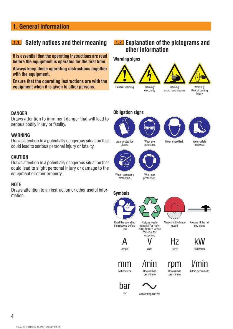
Explanation of the pictograms andother information
1.2
General warning Warning: electricity
Warning: avoid hand injuries
Warning signs
Obligation signs
Warning:Risk of cutting
injury
Wear protectivegloves.
Wear safetyfootwear.
Wear respiratoryprotection.
Wear eye protection.
Wear a hard hat.
Wear ear protection.
Symbols
Return waste material for recy-
cling Return waste material for recycling
Always fit the bladeguard
Always fit the railend stops
Read the operatinginstructions before
use
AAmps
VVolts
kWKilowatts
HzHertz
mmMillimeters
/minRevolutionsper minute
l/minLiters per minute
rpmRevolutionsper minute
barBar
i iAlternating current
Printed: 14.01.2016 | Doc-Nr: PUB / 5069668 / 000 / 03

5
2. Description
Description 2.1 Areas of application 62.2 D-LP 32/DS-TS 32 hydraulic saw system components 62.3 Parts and operating controls 8
Printed: 14.01.2016 | Doc-Nr: PUB / 5069668 / 000 / 03

6
2. Description
Areas of application
The D-LP 32/DS-TS32 is a medium to heavy-duty, high-performance wall saw system for use with saw bladesof up to 1600 mm dia. It is capable of cutting to a depthof 73 cm.The D-LP 32 hydraulic unit has a nominal power of 32 kW at 63 amps but can also be operated on 32 ampmains supplies.Its modular design permits rapid assembly and use formany different applications. The DS-TS32 saw head, forexample, can be used to power the Hilti DS-WSS 30 high-performance wire saw system.Using the D-RC-LP32 digital remote control unit to adjustthe infinitely variable oil flow rate, the operator can selectthe optimum speed and most suitable rate of advance.This feature ensures optimum efficiency for wall saw-ing, hydraulic coring, plunge sawing or wire sawing.
2.1 D-LP32/DS-TS32 hydraulic sawsystem components
The basic diamond saw system consists of the follow-ing components:
� D-LP32 hydraulic unit� D-RC-LP 32 remote control unit� DS-TS 32 saw head� D-R 200L rail� DS-C...H saw blade� DS-BG blade guard� D-PH/FH hydraulic hoses and water supply hose DS-ES-L end stop (2 end stops supplied with each
D-R..L rail) D-LP 32/DS-TS 32 tool set
2.2
9
1
2
7 3
5
4
6
8
Printed: 14.01.2016 | Doc-Nr: PUB / 5069668 / 000 / 03

7
2. Description
D-LP 32
D-R 50-230L
DS
-TS
32
DS-RF DS-RFP
D-EP-MLD
S-T
S 2
2
D-CO-MLDS-ES-L
DS-BG �800 - 1600 mm
DS-BGF �800 - 1600 mm
�D-FH14/14-10
D-LP15
D-PH58-10 (2x)
D-PH34-10 (2x)�D-FH4/14-103/
4" -
5/8
"�
(2x
)
D-RC-LP 32
DS
-TS
30
DS-ES-L
D-LP32/DS-TS 32Wall saws
2x DS-WS-SPP7DS-WSWS62x DS-WSRF5
DS-WSRP4DS-WSWD3DS-WSTA2DS-WSW5001
DS-W11
7
6
5
7 4
123
D-LP 32/DD-750 HY/DS-PS 30Hydraulic core drilling rigPlunge saw
D-LP32/DS-TS32/DS-WSS 30Wire saw
D-LP 32/DS-TS, PS, WSS and DD modular system2.2.1
D-R
150-
L
D-S
150
D-R
200-
L
DD-BA 6/DD-BA 3-70
DD-AF-HY
D-RC-LP 32
DD-CA-LDD-MF-ML
DD-7
50HY
DD-B
U-20
2
DD-R
100
-MDD
-R 4
0-M
D-CO
-ML
DS-CA-L/M
DD-R
130
-M
DS-P
S 30
D-LP 32
DD-FH
DS-B
O 6
00 -
1200
DS-BG 12-PS
PH
FH
D-R
100
-L
Printed: 14.01.2016 | Doc-Nr: PUB / 5069668 / 000 / 03

8
2. Description
Parts and operating controls
D-LP 32 hydraulic unit� Transport handle, hinged� Lifting point for transport by crane� 400 V 63 A socket, mains supply (Euro standard
socket as per EN CEE 63)� 230 V socket� Socket for D-RC-LP32 remote control unit� Oil level sight glass� Oil filter cover Emergency off switch Guidelines for use (sticker)
2.3
2.3.1
�� Wheels with puncture-proof tyres� PH 3/4ʺ coupling for pressure hose�� PH 3/4ʺ coupling for return hose�� FH 1/4ʺ couplings for advance control hoses�� FH 1/4ʺ couplings for saw arm �� Coupling for water supply from the site�� Water supply to saw head (with water flow rate reg-
ulation)�� D-RC-LP 32 remote control unit�� On / off control switch�� Cap / oil filler neck�� 230 V socket overload reset button� Front support�� Hinged transport handle locking mechanism
28171 7 68 12
10 1521 16 14 11
13
9 820 3 19
184 5
22
Printed: 14.01.2016 | Doc-Nr: PUB / 5069668 / 000 / 03

9
2. Description
Guidelines for use (sticker on D-LP 32 hydraulic unit)2.3.2
®Guideline • Richtlinie • Guide
D-LP 32 / DS-TS 32
3567
49
D-LP 32 / DS-TS 32 / WSS 30
45-50 Ampere
100 l/min
D-LP 32 / DD 750-HY
32-45 Ampere
40–60 l/min
32-63 Ampere
80–100 l/min
D-RC-LP 32
Start
Ampere
III
32 63
45
1001600 1200 1000 900 800mm
D-RC-LP 32
Start
Ampere
III
32 63
45
1001600 1200 1000 900 800mm
220 kg
D-RC-LP 32
Start
Ampere
III
32 63
45
1001600 1200 1000 900 800mm
6040
80
6040
80
6040
80
Printed: 14.01.2016 | Doc-Nr: PUB / 5069668 / 000 / 03

10
2. Description
D-RC-LP32 remote control� Remote control unit casing� Grips / control panel protection bars� Display and operating controls� Attachment point for belt fastener� Shoulder belt with fastener� Rear side of remote control unit: Sawing guidelines� Emergency OFF switch
2.3.3
Sawing guidelinesSee sticker on the rear of the D-RC-LP 32 remote con-trol unit.� Cutting depth for soft concrete / masonry� Cutting depth for hard concrete� Optimum blade diameter sequence� Plunge depth for initial guide cut� Plunge depth for subsequent cuts� Cut no. I - saw arm trailing� Cut no. II - saw arm leading Cut no. III - saw arm trailing Direction of blade rotation (counterclockwise, as
seen from side where blade is fitted) � Recommended oil flow rate in l/min. (speed) for
corresponding blade dia. (mm)
2.3.4
1 2 7
4
56
3 2
l. ll.lll.
lll.ll.l.
15 15 15
l. ll. lll. ....
cmHard
Guidecm
Tmax33cm
800 mm1. Tmax
43cm
1000 mm2. Tmax
53cm
1200 mm3. Tmax
73cm
1600 mm
3567
51/8
4.
800 100
1000
95
1200
85
1600 80
(mm)l/min
Soft 5
4 10 10 10
310 3 5413 3 2
69 7 89 9
Printed: 14.01.2016 | Doc-Nr: PUB / 5069668 / 000 / 03
D-RC-LP 32
Start
Ampere
III
32 63
45
1001600 1200 1000 900 800mm
806040
11
2. Description
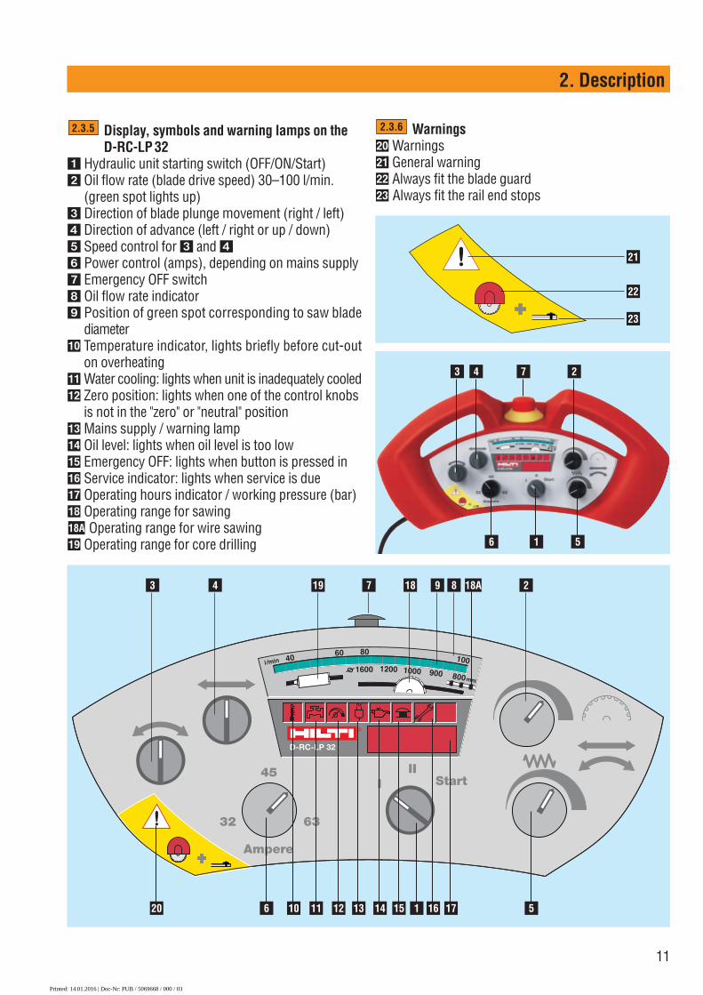
Display, symbols and warning lamps on theD-RC-LP 32
� Hydraulic unit starting switch (OFF/ON/Start)� Oil flow rate (blade drive speed) 30–100 l/min.
(green spot lights up)� Direction of blade plunge movement (right / left)� Direction of advance (left / right or up / down)� Speed control for � and �� Power control (amps), depending on mains supply� Emergency OFF switch Oil flow rate indicator Position of green spot corresponding to saw blade
diameter�� Temperature indicator, lights briefly before cut-out
on overheating� Water cooling: lights when unit is inadequately cooled�� Zero position: lights when one of the control knobs
is not in the "zero" or "neutral" position�� Mains supply / warning lamp�� Oil level: lights when oil level is too low�� Emergency OFF: lights when button is pressed in�� Service indicator: lights when service is due�� Operating hours indicator / working pressure (bar)�� Operating range for sawing
Operating range for wire sawing�� Operating range for core drilling
2.3.5
18A
Warnings�� Warnings� General warning�� Always fit the blade guard�� Always fit the rail end stops
2.3.6
3 4 19 7 18 9 8 2
21
22
23
20 6 10 11 12 13 14 15 1 16 17 5
3 4 7
6 1 5
2
18A
Printed: 14.01.2016 | Doc-Nr: PUB / 5069668 / 000 / 03

12
2. Description
DS-TS 32 saw head
� Saw arm with built-in motor� Blade guard holder (moves with the saw arm)� Carriage with wear-resistant cam-action steel rollers ��� Cam-action roller locking lever� Hydraulic coupling (PH 3/4ʺ) – pressure hose
Direction of oil flow� Hydraulic coupling (PH 3/4ʺ) – return hose� Hydraulic couplings (FH 1/4ʺ) – advance Hydraulic couplings (FH 1/4ʺ) – saw arm pivot Water supply
Water control valve: may be fitted at blade guard orat hydraulic unit
��Saw blade mounting flange with special M12×25 / 10.9grade steel screw ��
� Grips�� Cam-action rollers�� Clamping screw for positioning blade guard holder
and blade guards�� Cam-action roller lockbutton
2.3.7
5A
9A
11 87
17
9A
9
11
13
12
87
12
11
15
4
4
14
2
1
6
5
5A
15
3
12
16
2
10
18
11
12
�� Rating plate�� Grease nipple for cam-action roller bearing�� Holder for blade guard rubber�� Special M12×25 / 10.9 screw
5A
Printed: 14.01.2016 | Doc-Nr: PUB / 5069668 / 000 / 03
13
3. System components, tools and accessories
System components, 3.1 Hydraulic hoses and hydraulic hose set 14tools and accessories 3.2 D-R..L rails, DS-ES-L end stops, DS-RF rail supports
and DS-RFP angular cutting plate 143.3 DS-BG / BGF blade guard 143.4 DS-FCA-110 flush-cutting flange 143.5 Diamond saw blades 153.6 Accessories, D-LP 32/DS-TS 32 tool set 16
Printed: 14.01.2016 | Doc-Nr: PUB / 5069668 / 000 / 03

14
3. System components, tools and accessories
Hydraulic hoses and hydraulic hose set3.1
DS-PH34-10 DS-FH4/14-10hydraulic hose set hydraulic hose set (with water supply hose)
D-R50L railD-R100L railD-R150L railD-R200L railD-R230L railDS-ES-L end stop
D-R..L rails, DS-ES-L end stop, DS-RF rail support and DS-RFP angular cutting plate3.2
Accessories for securing and operating the saw
DS-BG / BGF blade guard3.3
DS-ES-L DS-RFPDS-RF
Item no. Designation Use
238000 DS-BG65 blade guard Blade guard for blades up to 650 mm dia.238002 DS-BG80 center section Blade guard for 600 to 900 mm dia. saw blades *238003 DS-BG80 side section Blade guard for 600 to 900 mm dia. saw blades238004 DS-BG120 center section Blade guard for 1000 to 1200 mm dia. saw blades *238005 DS-BG120 side section Blade guard for 1000 to 1200 mm dia. saw blades333883 DS-BG16 blade guard Blade guard for 1200 to 1600 mm dia. saw bladesItem no. Designation Use
238006 DS-BGF80 center section Blade guard for 600 to 900 mm dia. saw blades for flush cutting *238007 DS-BGF80 side section Blade guard for 600 to 900 mm dia. saw blades for flush cutting238008 DS-BGF120 center section Blade guard for 1000 to 1200 mm dia. saw blades for flush cutting *238009 DS-BGF120 side section Blade guard for 1000 to 1200 mm dia. saw blades for flush cutting256237 DS-BGF16 blade guard Blade guard for 1200 to 1600 mm dia. saw blades for flush cutting* Only to be used with the corresponding side sections!
DS-BG DS-BGF
D-R..L
Printed: 14.01.2016 | Doc-Nr: PUB / 5069668 / 000 / 03

15
3. System components, tools and accessories
Recommendations for use: Which specification for which material?
Diamond saw blades
We recommend Hilti CS-H, CM-H or CH-H saw bladesfor use with the D-LP32/DS-TS32. The saw blades canbe selected from the following table, taking material,steel content and dimensions into account.
3.5
Important■ Sawing at a lower speed (reduced saw blade r.p.m.) is usually advantageous when difficult conditions such as
high steel content or hard aggregates etc. are encountered.■ Safety precaution: Keep to the recommended settings in order to ensure that blade peripheral speed remains
within the safe range for the saw blade used.
DS-FCA-110 flush-cutting flange3.4
Specification Cutting characteristics Type of concrete Reinforcement
CS-H / UP Fast-cutting Soft aggregates Normal to high
CM-H / UP Well-balanced, good speed and life Hard aggregates Normal
CH-H / SP Fast-cutting and long life Soft to very hard aggregates Normal to high
Printed: 14.01.2016 | Doc-Nr: PUB / 5069668 / 000 / 03

3. System components, tools and accessories
D-LP32 / DS-TS32 tool set3.6
16
Ordering designation Qty. Use
D-LP32/DS-TS32 tool set 1 LP32/TS32 hydr. saw systemcomprising:Hilti plastic toolbox with insert 1 OperatorAccessories, list of contents and their use 1 OperatorFolding rule, 2 m 1 OperatorSTOF cleaning cloth 1 OperatorFlat brush 1 OperatorHilti spray 1 OperatorHilti grease dispenser 1 OperatorEar protectors 1 OperatorHSD-G M12 setting tool 1 � Setting anchorsBB blow out pump 1 � Anchor holesSpirit level 1 Assembling railsOpen-end / ring wrench, 19 mm 1 Assembling railsOpen-end / ring wrench, 18 mm 1 Assembling railsScrewdriver 1 AssemblyHammer 11/2 kg 1 Setting anchorsSocket, 19 mm AF 1 Assembling railsExtension, 1/2ʺ square drive 1 Assembling railsRatchet, 1/2ʺ square drive 1 Assembling railsD lever with 1/2ʺ square drive 1 Assembling railsD-CP-ML rail clamp 1 � Mounting railsHex. screw, M12×40/8.8 8 Fastening rail supportHex. screw, M12×70/8.8 8 Fastening rail supportWasher 8 Fastening rail supportClamping piece 1 Spare part rail supportWasher, 12×18×1 3 Spare part rail supportSpring, 1×12×25 3 Spare part rail supportM12 nut with collar 8 Angular cutting plateD-EP-ML 1/2ʺ eccentric pin 3 Rail extensionD-CO-ML taper 1 � Rail extensionRubber 2 Blade guard holderGrip nut 1 Fastening blade guardHex. key, 4 mm 2 Eccentric rollers / coversHex. key, 10 mm 1 Fastening blade guard holderDS hex. key with T-grip 1 Eccentric rollersD-PRT pressure release valve FH1/4ʺ 1 � Pressure release FH1/4ʺD-PRT pressure release valve PH3/4ʺ 1 � Pressure release PH3/4ʺD-steel wedge 130×70×20 6 � Securing concrete blockCopper ring 5 Core bit extensionSpecial M10 countersunk-head srew (6 screws) 1 Spare part, DS-FCA flangeSet of 3 seals 1 Spare part, DS-FCA flangeüpecial hex. screw, M12×25/10.9 2 Spare part, mounting saw bladeHose coupling, 15–24 mm 2 Attaching water hose
Additional accessories for the D-LP32/DS-TS32 (not included in the tool set)Ordering designation Qty. Use
DS-ES-L end stop 2 � Securing carriage LHKD-D M12×50 flush anchor 50 � 16 mm dia. holeWater valve Y-piece 1 � Water supplyWater valve 1 � Water supplyWater connector for saw head 1 Spare part for saw headHydraulic coupling, FH1/4ʺ (female) 1 Spare part for FH1/4ʺHydraulic coupling, FH1/4ʺ (male) 1 Spare part for FH1/4ʺHydraulic coupling, PH3/4ʺ (female) 1 Spare part for PH3/4ʺHydraulic coupling, PH3/4ʺ (male) 1 Spare part for PH3/4ʺHVLP 46 hydraulic oil (25 litres) 1 Hydraulic unitSharpening plate, 319 × 319 × 18 mm 1 Saw blades, core bidsD-RC-Ext 10 extension cable, 10 m 1 For remote control unitCEE 63 A plug socket (female) 1 Power extension cableShoulder belt with fastener RC-LP 32/TS 5-E 1 �� Spare part for remote control unitShoulder belt 1 � Spare part for 373243/5
�
�
�
�
�
�
�
�
�
�
�
��
Printed: 14.01.2016 | Doc-Nr: PUB / 5069668 / 000 / 03
17
4. Technical data
Technical data 4.1 Power supply 184.2 Dimensions and weights 184.3 IP enclosure protection code 18 4.4 Climatic conditions for operation and storage 184.5 Technical data 194.6 Noise information 194.7 Rating plates 20
Printed: 14.01.2016 | Doc-Nr: PUB / 5069668 / 000 / 03

18
4. Technical data
Power supply
Electric power supplyMains voltage: 400 V, 3-phase, 60 HzFuse rating: At least 32 amps,
63 amps recommended Generator: 60 kVA recommended
The generator must be earthed when in operation
Water supply for hydraulic unit, saw head and saw bladesCooling water: 7 l/min. at 4–6 bar; temp. 20°
Dimensions and weights
D-LP 32 hydraulic unitL×B×H 790×540×1090 mmWeight with oil 220 kg
remote control unit D-RC-LP 32L×B×H 390×180×120 mmWeight 2.2 kg
DS-TS 32 saw headL×B×H 510×380×400 mmWeight 36 kg
IP protection code
D-LP 32 hydraulic unit: IP 44D-RC-LP 32 remote control unit: IP 65
4.1
4.2
4.3
Climatic conditions for operationand storage
■ The nominal values given in the data for the D-LP 32 /DS-TS 32 hydraulic saw system are applic-able at ambient temperatures within the –15°C to+45°C range (hydraulic unit warmed up in advanceat temperatures below zero).
■ When dry, the units can be stored at temperaturesbetween –15°C and +50°C.
4.4
Printed: 14.01.2016 | Doc-Nr: PUB / 5069668 / 000 / 03
19
4. Technical data
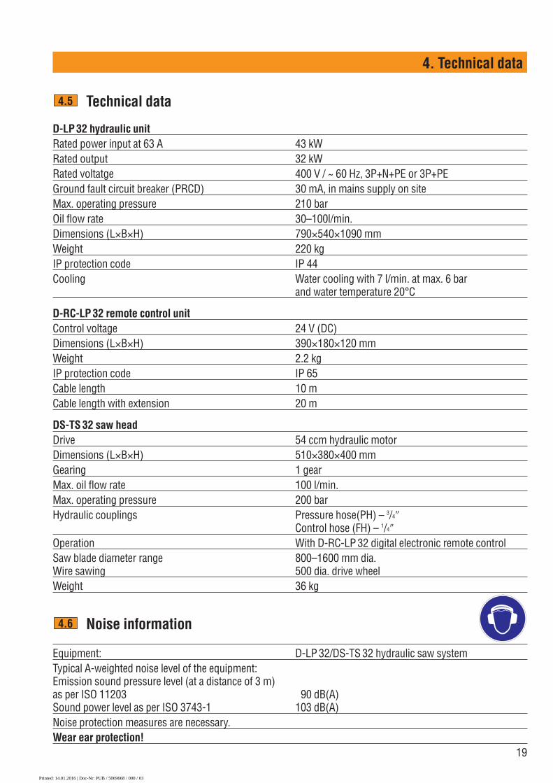
Technical data
D-LP 32 hydraulic unit Rated power input at 63 A 43 kWRated output 32 kWRated voltatge 400 V / ~ 60 Hz, 3P+N+PE or 3P+PEGround fault circuit breaker (PRCD) 30 mA, in mains supply on siteMax. operating pressure 210 barOil flow rate 30–100l/min.Dimensions (L×B×H) 790×540×1090 mmWeight 220 kgIP protection code IP 44Cooling Water cooling with 7 l/min. at max. 6 bar
and water temperature 20°C
D-RC-LP 32 remote control unitControl voltage 24 V (DC)Dimensions (L×B×H) 390×180×120 mmWeight 2.2 kgIP protection code IP 65Cable length 10 mCable length with extension 20 m
DS-TS 32 saw headDrive 54 ccm hydraulic motorDimensions (L×B×H) 510×380×400 mmGearing 1 gearMax. oil flow rate 100 l/min.Max. operating pressure 200 barHydraulic couplings Pressure hose(PH) – 3/4ʺ
Control hose (FH) – 1/4ʺOperation With D-RC-LP 32 digital electronic remote controlSaw blade diameter range 800–1600 mm dia.Wire sawing 500 dia. drive wheelWeight 36 kg
Noise information
Equipment: D-LP 32/DS-TS 32 hydraulic saw systemTypical A-weighted noise level of the equipment:Emission sound pressure level (at a distance of 3 m)as per ISO 11203 90 dB(A) Sound power level as per ISO 3743-1 103 dB(A)Noise protection measures are necessary.Wear ear protection!
4.5
4.6
Printed: 14.01.2016 | Doc-Nr: PUB / 5069668 / 000 / 03

20
4. Technical data
Rating plates4.7
Printed: 14.01.2016 | Doc-Nr: PUB / 5069668 / 000 / 03
21
5. Safety precautions
Safety precautions 5.1 General safety information 225.2 Use of the equipment as directed 235.3 Electrical safety precautions 235.4 Safety precautions during transport 235.5 Safety measures at the danger area 245.6 Preparations 245.7 Safety precautions to be observed when assembling,
securing and operating the wall saw. 255.8 Securing the objects being cut and disposal of sawing
slurry 25
Printed: 14.01.2016 | Doc-Nr: PUB / 5069668 / 000 / 03
unit at locations where there may be a risk of it falling(e.g. on scaffolding). The electric extension cable andits plugs and sockets must not be allowed to lie in water.Do not use the equipment in the vicinity of inflammableliquids or gases. Make provision for water removal anddisposal.■ Always keep the operating instructions with the equip-ment and pass them on to any subsequent user who hasbeen trained in its use.■ When not in use, store the hydraulic saw system ina locked, dry place out of reach of children. ■ Use the hydraulic saw system only for the applica-tions for which it has been designed.■ In addition to carrying out the specified care and main-tenance, careful cleaning is also a prerequisite for safe,trouble-free operation of the equipment. ■ Always stay alert and carefully observe the progressof your work. Proceed logically and do not use the equip-ment when you are unable to concentrate on your work.■ Do not leave tools (e.g. open-end wrenches) in placeon the equipment. Check the drive unit to ensure that alltools have been removed before switching on.■ Keep the working area tidy and well lit. An untidyworkplace and inadequate lighting increases the risk ofaccident.
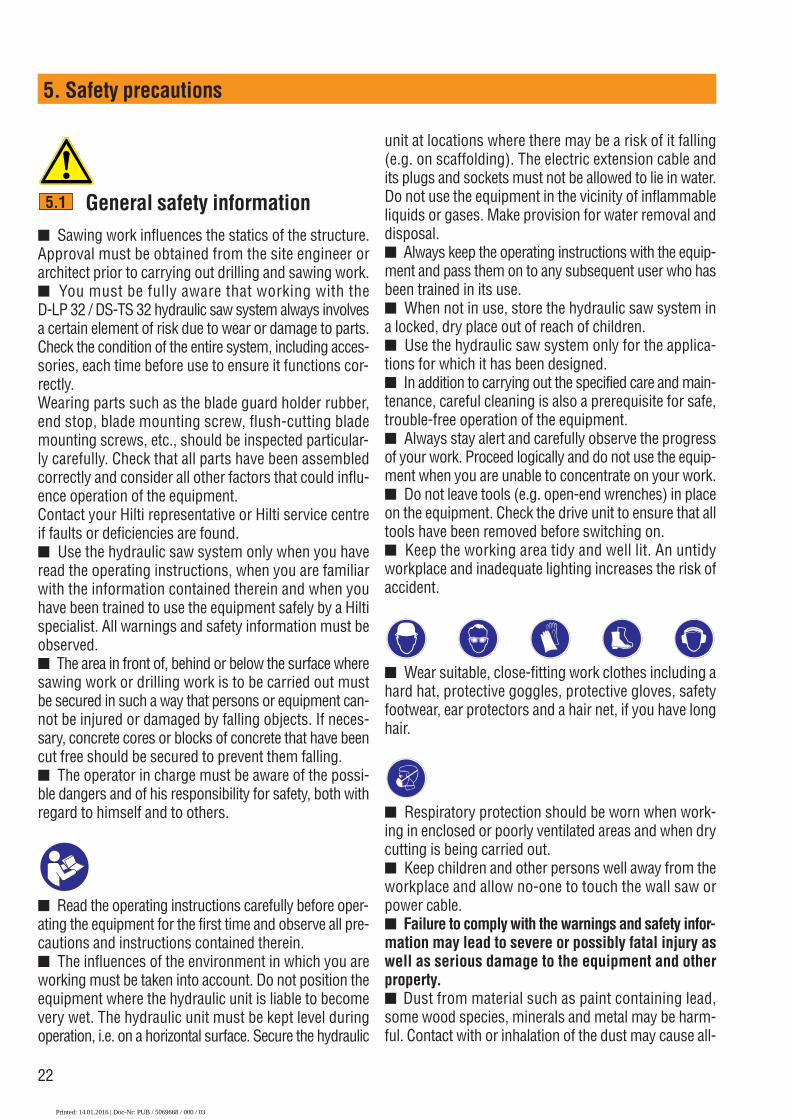
■ Wear suitable, close-fitting work clothes including ahard hat, protective goggles, protective gloves, safetyfootwear, ear protectors and a hair net, if you have longhair.
■ Respiratory protection should be worn when work-ing in enclosed or poorly ventilated areas and when drycutting is being carried out.■ Keep children and other persons well away from theworkplace and allow no-one to touch the wall saw orpower cable.■ Failure to comply with the warnings and safety infor-mation may lead to severe or possibly fatal injury aswell as serious damage to the equipment and otherproperty.■ Dust from material such as paint containing lead,some wood species, minerals and metal may be harm-ful. Contact with or inhalation of the dust may cause all-
22
5. Safety precautions
General safety information■ Sawing work influences the statics of the structure.Approval must be obtained from the site engineer orarchitect prior to carrying out drilling and sawing work.■ You must be fully aware that working with the D-LP 32 / DS-TS 32 hydraulic saw system always involvesa certain element of risk due to wear or damage to parts.Check the condition of the entire system, including acces-sories, each time before use to ensure it functions cor-rectly.Wearing parts such as the blade guard holder rubber,end stop, blade mounting screw, flush-cutting blademounting screws, etc., should be inspected particular-ly carefully. Check that all parts have been assembledcorrectly and consider all other factors that could influ-ence operation of the equipment.Contact your Hilti representative or Hilti service centreif faults or deficiencies are found.■ Use the hydraulic saw system only when you haveread the operating instructions, when you are familiarwith the information contained therein and when youhave been trained to use the equipment safely by a Hiltispecialist. All warnings and safety information must beobserved.■ The area in front of, behind or below the surface wheresawing work or drilling work is to be carried out mustbe secured in such a way that persons or equipment can-not be injured or damaged by falling objects. If neces-sary, concrete cores or blocks of concrete that have beencut free should be secured to prevent them falling.■ The operator in charge must be aware of the possi-ble dangers and of his responsibility for safety, both withregard to himself and to others.
■ Read the operating instructions carefully before oper-ating the equipment for the first time and observe all pre-cautions and instructions contained therein.■ The influences of the environment in which you areworking must be taken into account. Do not position theequipment where the hydraulic unit is liable to becomevery wet. The hydraulic unit must be kept level duringoperation, i.e. on a horizontal surface. Secure the hydraulic
5.1
Printed: 14.01.2016 | Doc-Nr: PUB / 5069668 / 000 / 03

23
5. Safety precautions
ergic reactions and/or respiratory diseases to the ope-rator or bystanders. Certain kinds of dust are classified as carcinogenic suchas oak and beech dust especially in conjunction withadditives for wood conditioning (chromate, wood pre-servative). Material containing asbestos must only betreated by specialists. Where the use of a dust extraction device is possibleit shall be used. To achieve a high level of dust collec-tion, use a suitable vacuum cleaner of the type recom-mended by Hilti for wood dust and/or mineral dusttogether with this tool. Ensure that the workplace iswell ventilated. The use of a dust mask of filter classP2 is recommended. Follow national requirements forthe materials you want to work with.■ Before beginning work, check the working area(e.g. using a metal detector) to ensure that no con-cealed electric cables or gas and water pipes are pre-sent. External metal parts of the machine may becomelive, for example, when an electric cable is damagedaccidentally. This presents a serious risk of electricshock.■ The machine is not intended for use by children, bydebilitated persons or those who have received noinstruction or training.■ Children must be instructed not to play with themachine.
Use of the equipment as directed
■ The D-LP 32/DS-TS 32 hydraulic saw system hasbeen developed for the technical demolition of steel, con-crete, stone or brickwork structures in construction andcivil engineering applications. It can be used for wet ordry sawing (the wet sawing technique is normally used).Use extending beyond this is considered to be not asdirected and requires to be clarified in advance with the manufacturer.■ The hydraulic saw system may be operated only byspecialists trained in concrete cutting techniques, referredto in the following as “operators”. These persons mustbe familiar with the content of these operating instruc-tions and must have been trained in their safe applica-tion by a Hilti specialist. ■ National regulations and laws, as well as the operat-ing instructions and the safety information applicable tothe accessories employed (saw blade, fastening acces-sories etc.) must be observed.
5.2
■ Use only the accessories recommended in these oper-ating instructions. The use of other accessories mayresult in damage or injury. Use only original Hilti spareparts.■ Use only saw blades approved for a cutting speed of63 m/sec.
Electrical safety precautions
■ Connect the unit only to a power source equippedwith an earth conductor and ground fault circuit break-er (PRCD). Check that these items are in perfect work-ing order before operating the equipment.■ Make sure that the mains voltage corresponds to thespecification given on the rating plate.■ Protect yourself against electric shock, i.e. avoid con-tact with earthed components such as pipes, radiatorsand the like.■ Check the condition of all cables and plugs each timebefore use.■ Keep all electric cables, especially their plug con-nections, in a dry condition. Close the electric socketsby means of the covers supplied when not in use.■ Use of extension cables: Use only extension cableswith adequate conductor cross-section which are approvedfor the intended field of use. Do not work with extensioncables when they are rolled up. This can result in a dropin output at the equipment and may cause the cable tooverheat. Replace damaged extension cables.■ Disconnect the power cable before beginning clean-ing and maintenance work or in the event of a lengthyinterruption between periods of operation.■ Any generator used must be earthed when in opera-tion.
Safety precautions during transport
■ Make sure that the hydraulic saw system cannot moveabout during transportation.■ Always avoid adopting a bent-over body position
5.4
5.3
Printed: 14.01.2016 | Doc-Nr: PUB / 5069668 / 000 / 03

5. Safety precautions
when carrying heavy items, i.e. keep your back straightwhen lifting and carrying. Maintain a secure stance, espe-cially when using ladders or when working from scaf-folding.■ Use the handles provided for transportation of thedrive unit and control unit. Ensure that the handles arealways kept clean and free of grease.■ If the drive unit and control unit are to be transport-ed by means of a crane, the lifting points provided mustbe used.■ Only suitable, conventional site cranes or mobilecranes may be used for lifting.
Safety measures at the dangerarea
■ Safety measures must be implemented in the areawhere sawing is taking place to ensure that operatorsand bystanders cannot be injured or property dama-ged by debris that may fly off or fall down (broken-offdiamond segments, small stones, sawing slurry, etc.)while sawing is in progress. Safety measures must alsobe implemented in the area not directly visible to theoperator, i.e. behind where sawing is taking place.■ Persons must NEVER enter the danger area (3 metersin all directions from the line of the cut to be made)while the blade drive is switched on.
3m 3m 3m
1m ∞
m
STOPSTOP
STOPSTOP
5.5
220 kg
CAUTIONSecure the working area. Ensure that no persons can beinjured or property / equipment damaged by falling objectsor debris that may fly off during the sawing operation.1. Approval must be obtained from the site engineer or
site management before beginning the sawing work.2. Find out whether overcutting at corners is permitted.
If not, the corresponding corner holes must be plannedand drilled first.
3. Check that the area is cordoned off, that supports arein place and warnings to third parties are displayed.
When setting up and operating the saw system andwhen removing parts that have been cut away, alwaysensure that no persons are below the area in which youare working. Falling objects could cause serious injury.
The danger area may be entered only when the machi-ne is switched off at the main switch.
Preparations
■ Keep the working area tidy and always unroll the fulllength of hoses and cables. Untidiness and bad organ-isation of the working area can lead to accidents.■ Make sure that no gas, water, electricity or other sup-ply lines are located in the cutting area. Supply lines locat-ed close to the cutting area which could be damaged byfalling parts, for instance, must be specially protectedand, if necessary, temporarily switched off etc.■ Ensure that the cooling water used is drained orextracted in a suitably controlled manner. Water that isallowed to drain away or spray around in an uncontrolledmanner can lead to damage or accidents. The fact thatwater could drain away into internal, hidden cavities, e.g.in brickwork or masonry, must also be taken into account.
5.6
3m
3m ∞
m
3m3m
STOP
STOP
STOP
STOP
24
Printed: 14.01.2016 | Doc-Nr: PUB / 5069668 / 000 / 03

25
5. Safety precautions
■ Make a careful note of any influence the immediatesurroundings may have on operations. Do not use thehydraulic saw system in areas where there is a risk ofexplosion or in close proximity to combustible materi-als, fluids or gases. Flying sparks or electrostatic dis-charge can lead to fires or explosions.■ Do not cut materials which may produce toxic orexplosive dust or vapours when cut.■ Do not cut easily combustible aluminium or magne-sium alloys.
Safety precautions to beobserved when assembling, securingand operating the wall saw■ Use metal anchors (size M12) for fastening DS-RFrail supports and DS-RFP angular cutting plates. Securefastenings of a type suitable for the material being cutmust be installed, e.g. Hilti HKD-D, HSA-A, Hilti HIT, HEA/ HAS anchors.■ Use only ISO 8.8 grade fastening screws for the railsupports.
■ An end stop must always be fitted at the end of therail to prevent unintentional advance beyond this point(prevents saw coming off the end of the rail).
■ The blade guard must always be in place when thesaw is in use. NEVER stand in the direction of radial flightof a running saw blade. Special precautions must be tak-en to secure the danger area when special cutting appli-cations are in progress.■ Always operate the machine from the closed side ofthe blade guard when corner cuts are made with theblade guard in the partly open position. The operatormust take additional precautions (fit a cover, plank ofwood, boards etc.) where necessary.■ Never attempt to connect or disconnect hydraulichoses while the hydraulic unit is running and while thehoses are under pressure.
5.7
■ Handle the DS-RFP angular cutting plate carefully. Thereis a risk of pinching your fingers.
■ It is essential that the prescribed checks are carriedout before beginning sawing (see section 5.5).
■ Unless special safety precautions are taken, the D-LP32/DS-TS 32 must NOT be operated in environments wherethere is a risk of explosion.■ The hydraulic unit and the operator with the remotecontrol unit should be positioned as far as possible out-side the danger zone. The operator with the remote con-trol unit should remain at a safe location while the sawis in operation.■ Use only adequately dimensioned fastening materi-als to secure the saw (anchors, screws, etc.). Recom-mendations can be found in our catalogues and bro-chures.■ Operate the saw only when the blade guard and rail-end stops have been fitted and secured.■ Observe the recommended cutting speeds and advancepressures while sawing.■ Protective gloves should be worn as the oil and partsof the equipment can become very hot.■ Wear the protective clothing and other items of pro-tective equipment listed in section 5.1.■ Before each cut, check that there is no play betweenthe saw head and the rail and that the eccentric rollersare engaged.■ When additional safety precautions are taken, over-head sawing is also possible. In this case, the blade guardmust be equipped with a means of water drainage. Donot stand beneath the saw.
Securing the objects being cutand disposal of sawing slurry
■ Steel wedges and/or supports must be used to pre-
5.8
Printed: 14.01.2016 | Doc-Nr: PUB / 5069668 / 000 / 03

26
5. Safety precautions
vent uncontrolled movement of parts being cut free inorder to avoid injuries and to prevent the saw bladebecoming trapped or jammed.■ Use only approved and appropriately dimensionedmeans of securing and lifting for the removal and trans-portation of parts that have been cut free. Such partsmay have a weight of many tons.■ Never loiter in the vicinity of loads suspended bycranes.■ The point at which the cut is made and any resultingopening must be safely and visibly cordoned off to pre-vent persons falling and to exclude the risk of damageor injury.■ Introducing sawing slurry into the drains or sewagesystem without suitable pre-treatment is problematicfrom an environmental point of view. Ask the local author-ity responsible about existing regulations. We recom-mend the following pre-treatment:– Collect the sawing slurry (e.g. using an industrial vac-
uum cleaner)– Allow the slurry to settle and dispose of the solid por-
tion of the waste at a building waste disposal location(the separation process can be accelerated by addinga flocculent).
– Neutralise the residual water by adding a neutralisingagent or dilute it by adding a large quantity of waterbefore allowing it to enter the drainage system.
Printed: 14.01.2016 | Doc-Nr: PUB / 5069668 / 000 / 03

27
6.Before use
Before use 6.1 Preparations at the workplace and preparing the saw system 286.2 Setting up the saw system 296.3 D-LP32 hydraulic unit: Connections and preparation for use 34
Printed: 14.01.2016 | Doc-Nr: PUB / 5069668 / 000 / 03

overcutting at corners is permitted. If not, the corre-sponding corner holes must be planned and drilled first.
■ Check that the area is cordoned off, that supports arein place and warnings to third parties are displayed.
Planning the cutting sequence, marking thecutting line and fastening points■ The parts to be cut out are usually marked by the client.
A rational cutting sequence can be followed when therail supports are cleverly positioned.
■ If necessary, adjust the size and weight of the concreteblocks to the prevailing conditions by making dividingcuts, e.g. in accordance with the work order, the meansof handling the blocks, the crane or the maximum floorloading capacity.
Steel wedges can be used as necessary to secure the cut-out concrete blocks.Designation: steel wedge
Supporting / securing concrete blocksConcrete blocks with a weight of several hundred kilo-grams may be cut out during sawing. Secure the blocksas necessary, before beginning sawing, as shown in thefollowing examples:
6.1.4
6.1.5
28
6. Before use
Preparations at the workplace andpreparing the equipment
Observe the safety precautions listed in section 5.
Power requirements and cooling water■ Check the electric supply fuse rating (63 amps is best
and 32 amps is the minimum) and check functionalityof the earth connection (this is the responsibility of thesite manager).
■ Use an electric extension cable with standard Euro plugas per EN CEE 63. Select the cable cross section accord-ing to the load it is to carry (amps) and the cable length.Please refer to the following table:
Cable conductor cross section (F)Current Hydrau- F mm2 Fmm2 Fmm2 F mm2 F mm2
Amps (A) lic unit 2,5 4 6 10 1632 LP32/400V 24 39 59 98 *40 LP32/400V 20 31 47 78 12563 LP32/400V 20 30 50 80* maximum cable length in metres
Electric cable
Pin assignment for CEE 63 plug on D-LP32LP32, 400 V, 3 P + N + PE
PE = earth L1 = phaseN = neutral L2 = phase
L3 = phase
■ The CEE 63 plug, male type, complies with the IEC 309-2 standard.
■ Ensure that the water supply has a max. pressure of 6 bar and a flow rate of at least 7 l/min. at a tempera-ture of less than 20°C.
■ Make suitable arrangements for water removal, depend-ing on the job and situation, e.g. water barriers, wet-type vacuum cleaner, cover with plastic sheets, etc.
Clarify the situation and secure the workplace■ Obtain approval from the site engineer or site man-
agement before beginning sawing. Find out whether
6.1
6.1.1
6.1.2
6.1.3
L3
L2
L1PE
N
F mm2
1st cut 2nd cut 3rd cut 4th cut 5th cut
Printed: 14.01.2016 | Doc-Nr: PUB / 5069668 / 000 / 03
29
6. Before use
Setting up the saw system
Securing to the base material■ The saw system can be used efficiently and safely only
when anchored rigidly and securely to the base mate-rial. We recommend use of Hilti drilling machines andanchor systems.
■ The rail supports and angular cutting plates must besecured with anchors suitable for the base material.
WARNINGUse an anchor suitable for the material on which youare working and observe the anchor manufacturer’sinstructions.NOTEHilti M12 metal expansion anchors are usually suitablefor fastening diamond core drilling equipment to uncrackedconcrete. Under certain conditions it may be necessaryto use an alternative fastening method. Please contactHilti Technical Service if you have any questions aboutsecure fastening.■ When placing the Hilti HKD M12 metal expansion anchor,
for example, a minimum distance of 20 cm to the near-est edge must be observed. The dust must be blownout of the holes and the anchors set approx. 5 mm belowthe surface of the concrete.
■ On masonry, etc., for example, Hilti HIT adhesive anchorsor through rods may be used.
■ On extremely uneven surfaces, suitable shims or pack-ing pieces must be positioned beneath the rail supportswhere necessary, or the rail support adjustment screwsadjusted accordingly.
■ The most frequently used anchor on reinforced con-crete:
Recommended by Hilti:HKD-D M12×50, d 16
The use of galvanised screws is recommended.
6.2
6.2.1
approx. 5 mm
d�
mm
washer
M12×40 screw8.8. grade
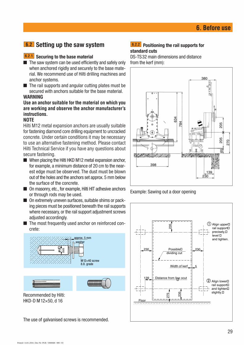
Positioning the rail supports for standard cutsDS-TS32 main dimensions and distance from the kerf (mm):
Beispiel: Türöffnung sägen
Example: Sawing out a door opening
6.2.2
5
235
230
139 Distance from line ocut
235
275
Possible�dividing cut
Floor
Width of kerf
� Align upper� rail support� precisely,� level � and tighten.
� Align lower� rail support� and tighten� slightly.�
230
�
Printed: 14.01.2016 | Doc-Nr: PUB / 5069668 / 000 / 03

30
Mounting D-R..L rails, clamping piece and railextension■ D-R...L rails are available in 50, 100, 150, 200 and
230 cm lengths■ Use the D-CP-M/L clamping piece when the rail is
mounted vertically. Attach the clamping piece to the D-R..L rail and hook it into the upper, previously alignedand levelled DS-RF rail support. �
■ Position the lower end of the rail in the lower rail sup-port (not yet fully tightened), slide up the clamping plateand tighten the M12 screw. Check the distance fromthe cutting line and alignment of the rail before fullytightening the screw ➋
■ When mounting the rails, always position the rail sup-port at right angles to the rail and then tighten all railfastening screws securely.
■ All Hilti D-R..L rails can be extended to form a rigid unitby using a D-C-O-ML double taper and D-EP-ML eccen-tric pin.
■ The recommended distance between rail supports isapprox. 1.5 m.
■ When a double taper is not available for use, rails canbe extended by mounting a rail support at the jointbetween two rails. In this case, use a DS-ES-L end stopto set the correct distance between rail sections.
6.2.3 ■ D-R..L rails are also used as the column in the DD-750 HY hydraulic drilling system.
■ Fit the end stop after mounting the rail.
1
2
DS-RFrail support�� Clamping plate with M12 screw (19 mm AF)
Rail support withclamping plate
Attach the clamping piece
D-CO-ML double taper
D-EP-ML eccentric pin
D-CP-ML clamping piece
DS-ES-L end stop
6. Before use
Use a D-CO-ML doubletaper to extend rails orposition a DS-RF rail sup-port at the joint betweenthe rails.
DS-ES-LDS-RF
DS-RF
DS-ES-L
Printed: 14.01.2016 | Doc-Nr: PUB / 5069668 / 000 / 03

31
Mounting the DS-TS32 saw head, hydraulichoses and saw blade■ The pivoting saw arm � should be in the starting posi-
tion (pointing vertically upwards). Press the release but-tons ➌with the thumbs and pivot the grips ➋ throughapprox. 180° outwards towards the saw arm. The cam-action rollers ➍ on the saw arm side are now in theopen position.
■ Position the saw head on the rail (rail already fastenedsecurely), engage the carriage with the teeth on therack and close the cam-action rollers by pressing thelockbuttons with the thumbs and pivoting the grips intothe closed position.
■ Connect the D-PH 34 hydraulic hose ➎ (PH 3/4ʺ pres-sure hose for the motor) and the D-FH 4/14 hose set(➏ FH 1/4ʺ control hose) to the saw head.
■ Bring the blade guard holder ➐ into a suitable positionon the saw arm. Use the hex. wrench (10 mm AF) totighten the hex. screw in the centre of the saw armsecurely before mounting the saw blade. The holderand the blade guard then remain in the desired posi-tion during the entire sawing procedure
■ The grips ➑ are used for carrying the saw head.
6.2.4 Mounting the saw blade ■ Select the saw blade (diameter, Hilti type CS-H, CM-H
or CH-H) depending on the concrete, the job to be doneand the cutting sequence using saw blades of differ-ent diameters.
■ Position the saw blade, observing the correct directionof rotation, on the drive hub of the saw arm.
■ Fit the special blade flange ➒ and the special screw➓ M12×25 (10.9 grade).
■ Rotate the blade slightly so that the countersunk holesfor fastening the blade for flush cutting are positionedBESIDE the 6 water grooves.
■ Use the 19 mm AF ring wrench to tighten the specialM12 screw securely ➓.
Instructions for handling hydraulic hoses andhydraulic couplings■ Always clean the couplings with a cloth before con-
necting. Turn the securing ring on the coupling afterthe click is heard.
■ To ensure reliable operation and extend the life of theentire system, it is important that all hydraulic couplingsare cleaned daily.
■ Do not leave hydraulic couplings lying in the dirt anddo not knock them against concrete surfaces. Avoiddragging hydraulic hoses over sharp edges.
■ After transporting all modules to the workplace, thehydraulic unit should be positioned correctly and thehydraulic hoses connected to the unit immediately. Thisprevents pressure building up in the hoses even whendirectly exposed to the heat of the sun.
■ Should the hydraulic hoses prove difficult or impossi-ble to connect even after relieving pressure in the sys-tem by operating all valves (controls), the D-PRT pres-sure release valve can be used to release excess pres-sure from the hoses. The small quantity of escaping oilshould be caught in a cloth.
■ Before disconnecting couplings, turn the locking sleeveuntil it engages in the "open" position.
6.2.5
D-PRT FH 1/4ʺ pressure release valve
D-PRT PH 3/4ʺ pressure release valve
6. Before use
�
�
�
�
�
�
∅ 120 mm
�
Printed: 14.01.2016 | Doc-Nr: PUB / 5069668 / 000 / 03

32
Blade guard■ Always ensure that the DS-BG blade guard is in place
when the saw is in operation.■ The blade guard is in two sections to permit cutting
into corners.■ Thanks to its symmetrical design, the blade guard can
simply be turned to permit cutting into a corner to theleft or right (or upwards and downwards) withoutremoving the blade from the kerf.
■ Use the 10 mm AF hex. wrench to tighten the bladeguard holder. The blade guard than always remains inthe same position.
■ Use the DS-BGF blade guard (open on one side) for flushcutting.
Using the DS-RFP angular cutting plate■ The angular cutting plate is used for sawing on stairs,
in tunnels and for cutting at an angle of up to 45°.■ Align the equipment by using a protractor to measure
the angle at the blade when mounted on the saw.■ Due to the angle of the blade, cutting depth is reduced.
The blade is also subjected to additional bending loads.Please refer to the following table for setting-up dimen-sions and cutting depths.IMPORTANT: When making angular cuts, make a shal-low guide cut and begin cutting gently!
6.2.7
6.2.6
Angle of cut 10° 20° 30° 40° 45°Diameter mm) 900 900 900 900 900C (cm) 30 24 18 8 3A (cm) 24 26 29 34 38
Flush cutting using the DS-FCA-110 flush-cutting flange■ As for standard sawing applications, the blade can be fit-
ted after the saw has been mounted on the rail. (Old method:The saw and the fitted saw blade had to be lifted togeth-er onto the rail and the saw blade guided into the kerf.)
■ The Hilti saw system can be preassembled and posi-tioned precisely, to the millimetre.
■ The electric remote control system permits the sawarm to be pivoted effortlessly to the height of the sawblade mounting hole.
■ Spindle speeds and the sawing procedure are as forstandard applications.
6.2.8
DS-RFP
6. Before use
DS-BG
DS-BGF
3 4
DS-BGF
21
DS-FCA
Printed: 14.01.2016 | Doc-Nr: PUB / 5069668 / 000 / 03

33
6. Before use
5 mm183 mm274 mm
150 mm
424 mm
205
mm
270
mm
D-LP 32/DS-TS 32 tool set■ The tool set contains all the tools necessary for installing
and mounting the saw and includes safety-relevantparts, fastening screws, nuts etc.
■ Use of the Hilti tool set ensures that the equipmentcan be operated correctly and safely.
■ All tools and parts contained in this set, their func-tions and item nos. for reordering, are described inthe manual included with the set.
6.2.9
DS-TS 32 hose and cable connections■ Two PH 3/4ʺ hoses and one FH 1/4ʺ hose set are used to
connect the saw head to the hydraulic unit.■ All functions can be controlled only by way of the
D-RC-LP 32 electric remote control unit.■ The hydraulic hoses and remote control cable have
a standard length of 10 metres.This length can be extended, but a drop in performancemust then be expected.
Using other hydraulic units to power the DS-TS 32 saw ■ Damage to the DS-TS 32 resulting from use of a hydraulic
unit other than the D-LP 32 or D-LP 30 to power thesystem is not covered by the warranty provided by theHilti Corporation.
■ Should you decide to operate the saw, at your own risk,with a hydraulic unit of a type not specified by Hilti, thehydraulic unit used must fulfil the following conditions:■ Oil flow rate 80–100 l/min.■ Maximum operating pressure 190 bar.■ Modifications to the DS-TS 32 hydraulic couplings
are NOT permitted (see illustration showing direc-tion of oil flow).
■ The user carries the responsibility for ensuring thatthe control system employed functions correctly.
6.2.11
6.2.10
D-LP 32/DS-TS 32 tool set
1x DS-FH 4/14-10
D-RC
-LP
32
Direction of oil flow (pressure hose)Direction of oil flow (return hose)
Printed: 14.01.2016 | Doc-Nr: PUB / 5069668 / 000 / 03

� Socket for D-RC-LP 32 remote control unit.� Keep the hydraulic couplings clean. When connecting
the hoses, turn the securing ring after the couplingengages with an audible "click".
� D-RC-LP 32 remote control unit. Water system connection (FH1/4ʺ hose set to saw head). Disconnect the water supply hose after finishing work.
Water then drains from the hydraulic unit (oil cooler).automatically (also disconnect the water system hose).
�� Cap / oil filler neck� Oil filter cover�� Guidelines for use (sticker)�� Emergency OFF switch�� 230 V socket (max. 10 amps) for light-duty rotary ham-
mer drills and lights, etc.�� Rating plate�� On / off control switch�� Overload reset button (230 V socket)�� Lifting point for transport by crane
34
6. Before use
D-LP32 hydraulic unit Connections and preparation for use6.3
� 3-phase 400 V mains supply with appropriate fuse rat-ing. The switching control sets the correct direction ofmotor rotation automatically. Standard plug as per ENCEE 63.
� The unit employs a star / delta switching system (Y-∅). Starting up takes only a few seconds (max. 5 sec.).
� Use an extension cable with adequate cross section.The unit will not start if the voltage supply is too low orif one of the phases is too weak.
� The water supply is always connected to the lower cou-pling on the hydraulic unit. Water pressure max. 6 bar,flow rate at least 7 l/min. at temperature below ≤ 20ºC.We recommend that the jobsite water supply connec-tion is equipped with a non-return valve, in accordancewith national regulations.
61311 1213 187
894 6
17 2 13 1 3 10
1614 15 5
Printed: 14.01.2016 | Doc-Nr: PUB / 5069668 / 000 / 03
35
7. Operation
Operation 7.1 Checks before beginning sawing 367.2 The sawing procedure and saw operation 377.3 Guidelines and guide values 387.4 Dismantling the saw system 41
Printed: 14.01.2016 | Doc-Nr: PUB / 5069668 / 000 / 03

36
7. Operation
Checks before beginning sawing
■ On-site preparations must be completed (supports,water collection, etc.).
■ The hydraulic unit must be positioned outside thedanger zones. The areas in front of and behind thecomponent where sawing is to take place are dangerzones and must be secured and cordoned off. No per-sons may remain in a danger zone.
■ The power cable and water supply must be connect-ed. The power supply must be earthed and equippedwith a ground fault interrupter (PRCD). The watersupply must be within the permitted pressure range.
■ The rail supports and rails must be aligned and fas-tened correctly, with all screws and nuts tightenedsecurely.
■ The saw head must be mounted without play and thecam-action rollers engaged.
■ The hydraulic hoses and water hoses must be laidout, connected correctly and the locking sleevesengaged.
■ The saw blade must be mounted in the correct direc-tion of rotation and the central screw at the saw bladeflange (or six M10 countersunk screws) tightenedsecurely.
■ The blade guard and end stop must be fitted secure-ly.
■ The remote control unit, power supply cable and watersupply hose must be connected.
■ The emergency OFF buttons on the hydraulic unit andremote control unit must be disengaged (pulled out).
■ All control knobs on the remote control unit andhydraulic unit must be in the "off" or, respectively, (I)position or the "neutral / zero" position.
■ The operator should carry the remote control unit(using the shoulder strap).
■ The safety precautions must be observed.
7.1
Printed: 14.01.2016 | Doc-Nr: PUB / 5069668 / 000 / 03

Press the emergency OFF button in theevent of encountering a critical or dan-gerous situation while sawing!
1 Open the water valve at the hydraulic unit (flow rate at least 7 l/min., pressure max. 6 bar).2 Set the control switch on the hydraulic unit to the "on" (I) position.3 Turn the current control knob � to the desired setting: depending on the power supply available, usually
between 32 and 63 amps (maximum power at 63 amps, reduced power at 32 amps).4 Turn knob � and then back to position "II". The star (Y) - delta (Δ) motor start-up procedure takes approx.
five seconds. Do not manipulate any other controls until the Y-Δ start-up switching sequence is heard to becompleted.
5 Use the direction control knobs �, � and the speed control knob � to bring the saw head to the starting position and then return the switches to the "neutral/0" position
6 Control knob � should then be used to set the desired speed (according to blade diameter) or, respec-tively, the oil flow rate . The display �� indicates the current operating pressure (bar).
7 Using control knobs � and � , pivot the saw arm / blade until the desired cutting depth is reached andthen return the knobs to the "neutral/0" position. Guideline: Please refer to the sticker on the rear of the D-RC-LP 32 remote control unit for cutting depths, guide cuts and cutting sequence.
8 Use knob � to select sawing direction and set the speed control knob � to maximum. Optimise power output by adjusting the current control knob �. Make the guide cut with a pressure of max. 110 bar.
9 Repeat step number 7 until the desired depth of cut is reached.10 After reaching the final depth, use knobs � and � to move the saw arm into the 90° position (away from
the rail) and then use knobs � and � to move the saw head to the desired position on the rail. Turn thespeed control knob � (oil flow rate) back to zero and switch off the drive with switch � (the saw bladestops rotating). Check again that all control knobs are in the "neutral/0" position. Finally, press in the emergency OFF button � on the remote control unit.
11 Close the water valve on the hydraulic unit.12 Switch off the hydraulic unit.
37
7. Operation
The sawing procedure and saw operationPlease refer to the D-LP 32 hydraulic unit application guidelines sticker, section 2.3.2, page 9.
7.2
D-RC-LP 32
Start
Ampere
III
32 63
45
1001600 1200 1000 900 800mm
806040
3 4 7 8 9 2
6 1 10 5
Printed: 14.01.2016 | Doc-Nr: PUB / 5069668 / 000 / 03
38
Guidelines and guide values
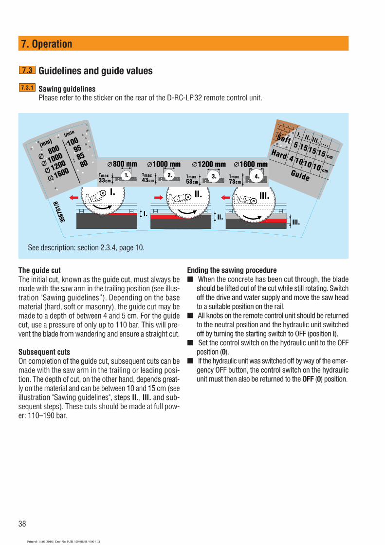
Sawing guidelinesPlease refer to the sticker on the rear of the D-RC-LP32 remote control unit.
7.3.1
7.3
l. ll.lll.
lll.ll.l.
15 15 15
l. ll. lll. ....
cmHard
Guidecm
Tmax33cm
800 mm1. Tmax
43cm
1000 mm2. Tmax
53cm
1200 mm3. Tmax
73cm
1600 mm
3567
51/8
4.
800 100
1000
95
1200
85
1600 80
(mm)l/min
Soft 5
4 10 10 10
7. Operation
See description: section 2.3.4, page 10.
The guide cutThe initial cut, known as the guide cut, must always bemade with the saw arm in the trailing position (see illus-tration "Sawing guidelines”). Depending on the basematerial (hard, soft or masonry), the guide cut may bemade to a depth of between 4 and 5 cm. For the guidecut, use a pressure of only up to 110 bar. This will pre-vent the blade from wandering and ensure a straight cut.
Subsequent cutsOn completion of the guide cut, subsequent cuts can bemade with the saw arm in the trailing or leading posi-tion. The depth of cut, on the other hand, depends great-ly on the material and can be between 10 and 15 cm (seeillustration "Sawing guidelines", steps II., III. and sub-sequent steps). These cuts should be made at full pow-er: 110–190 bar.
Ending the sawing procedure■ When the concrete has been cut through, the blade
should be lifted out of the cut while still rotating. Switchoff the drive and water supply and move the saw headto a suitable position on the rail.
■ All knobs on the remote control unit should be returnedto the neutral position and the hydraulic unit switchedoff by turning the starting switch to OFF (position I).
■ Set the control switch on the hydraulic unit to the OFFposition (0).
■ If the hydraulic unit was switched off by way of the emer-gency OFF button, the control switch on the hydraulicunit must then also be returned to the OFF (0) position.
Printed: 14.01.2016 | Doc-Nr: PUB / 5069668 / 000 / 03
39
7. Operation
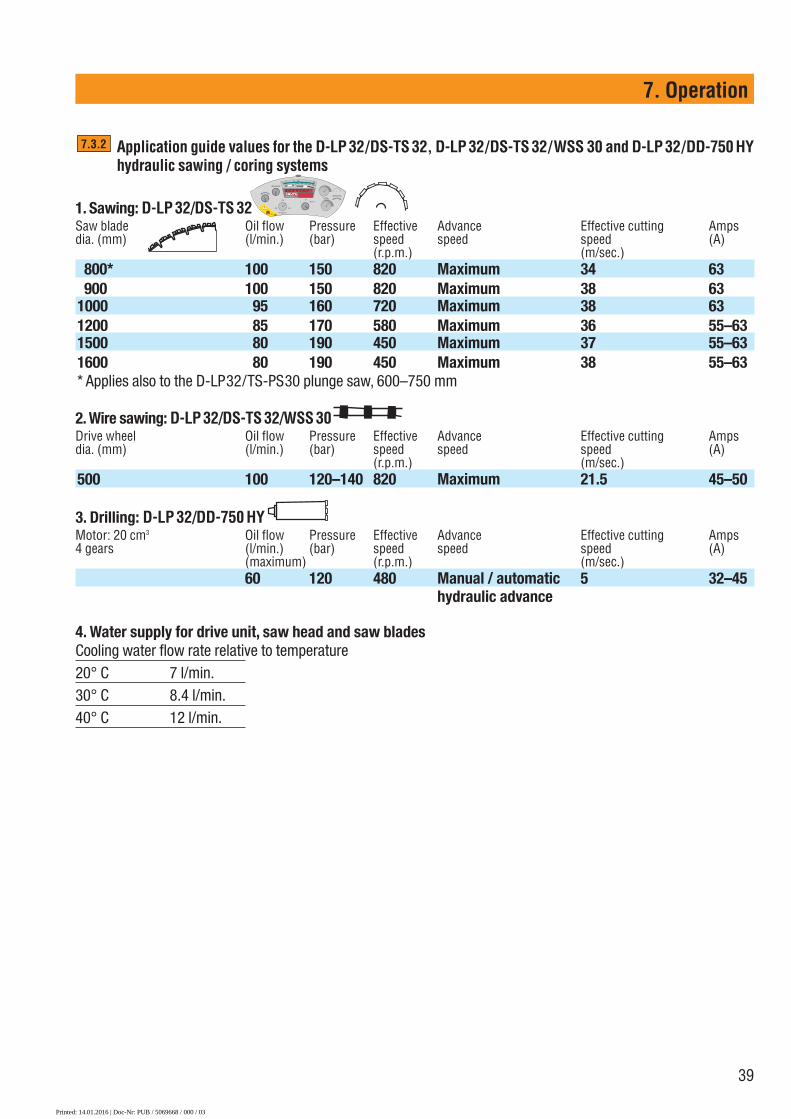
Application guide values for the D-LP 32/DS-TS 32, D-LP 32/DS-TS 32/WSS 30 and D-LP 32/DD-750 HYhydraulic sawing / coring systems
1. Sawing: D-LP 32/DS-TS 32Saw blade Oil flow Pressure Effective Advance Effective cutting Ampsdia. (mm) (l/min.) (bar) speed speed speed (A)
(r.p.m.) (m/sec.)800* 100 150 820 Maximum 34 63900 100 150 820 Maximum 38 63
1000 95 160 720 Maximum 38 631200 85 170 580 Maximum 36 55–631500 80 190 450 Maximum 37 55–631600 80 190 450 Maximum 38 55–63* Applies also to the D-LP32/TS-PS30 plunge saw, 600–750 mm
2. Wire sawing: D-LP 32/DS-TS 32/WSS 30Drive wheel Oil flow Pressure Effective Advance Effective cutting Ampsdia. (mm) (l/min.) (bar) speed speed speed (A)
(r.p.m.) (m/sec.)500 100 120–140 820 Maximum 21.5 45–50
3. Drilling: D-LP 32/DD-750 HYMotor: 20 cm3 Oil flow Pressure Effective Advance Effective cutting Amps4 gears (l/min.) (bar) speed speed speed (A)
(maximum) (r.p.m.) (m/sec.)60 120 480 Manual / automatic 5 32–45
hydraulic advance
4. Water supply for drive unit, saw head and saw bladesCooling water flow rate relative to temperature20° C 7 l/min.30° C 8.4 l/min.40° C 12 l/min.
7.3.2
D-RC-LP 32
Start
Ampere
III
32 63
45
1001600 1200 1000 900 800mm
806040
Printed: 14.01.2016 | Doc-Nr: PUB / 5069668 / 000 / 03

40
Remaining distances for the DS-TS32/30 saw heads
DS-TS 32 remaining distances
7.3.4
DS-TS 32 remaining distances
Remaining distance A (cm)S A(cm) 800 900 1000 1200 1500 1600
mm dia. mm dia. mm dia. mm dia. mm dia. mm dia.
20 9 8 7 6 5 430 23 18 15 12 9 840 31 22 16 1550 39 25 2360 40 3570 56
Remaining distance B in (cm)S B(cm) 800 900 1000 1200 1500 1600
mm dia. mm dia mm dia mm dia mm dia mm dia
20 35 37 40 45 51 5330 39 42 46 52 60 6240 49 56 66 6950 59 71 7460 73 7770 79
7. Operation
Saw blade diameters and cutting depths for the DS-TS 32, DS-TS 30 and DS-TS 22/C saw heads
Cutting depths T (cm)Saw blade diameter DS-TS 22/C T DS-TS 30 T DS-TS 32 T
2 gears (cm) 2 gears (cm) 1 gear (cm)
500 mm dia.* �* ×m �*600 mm dia. 23 � 23700 mm dia. 28 � 28750 mm dia. 31 � 31800 mm dia. * 33 33 33900 mm dia. 38 * 38 * 38
1000 mm dia. 43 43 431200 mm dia. 53 53 531500 mm dia. 68 681600 mm dia. 73 73* Largest initial diamter, main application, � possible application�* 500 mm dia. drive pulley for the Hilti DS-WSS30 wire saw system, unlimited cutting depth × metres (m)
7.3.3
Printed: 14.01.2016 | Doc-Nr: PUB / 5069668 / 000 / 03

41
7. Operation
Dismantling the saw system
■ Secure the block of concrete you have cut. Use steelwedges when necessary.
■ Clean the equipment by spraying with water. Dry theparts with a cloth.
■ Remove the blade guard, blade and other modules (fol-lowing assembly instructions but in reverse order).
■ Secure the concrete block(s) or withdraw them care-fully from the hole and make arrangements for theirtransport.
■ Cordon off the opening so that it presents no hazardto third parties.
7.4
7.3.5 Operating the D-LP 32 with 2-speed gear DS-TS 30 (previous model), selecting the gear, guide values,sawing procedure, saw blades for the 2-speed gear D-LP 32/DS-TS 30 hydraulic saw system
Optimum saw blade cutting speed (peripheral speed): A guide value of approx. 40 m/sec. is recommended by most sawblade manufacturers, including Hilti. Depending on the situation (concrete quality, aggregates, steel content, etc.), speedsof between 30 and 50 m/sec. can be used.
®Guidelines for D-LP32 with 2-speed gear DS-TS 30
D-LP32 / DS-TS 30 in 1st gear 1st gear: 800–1600 dia.
3567
49/2
D-LP32 / DS-TS30 in 2nd gear
D-LP32 / DS-TS30/WSS30 in 1st gear
32–63 Ampere
80–100 l/min.
D-RC-LP 32
Start
Ampere
III
32 63
45
1001600 1200 1000 900 800mm
6040
80
32–63 Ampere
80–100 l/min.
D-RC-LP 32
Start
Ampere
III
32 63
45
1001600 1200 1000 900 800mm
6040
80
45–50 Ampere
100 l/min
D-RC-LP 32
Start
Ampere
III
32 63
45
1001600 1200 1000 900 800mm
6040
80
All settings same asfor D-LP32 / DS-TS32
1st gear: 500 dia.drive wheel
All settings same asfor D-LP32 / DS-TS32
1st gear: 700–750 dia.Actual dia. Diameter settings
on remote control unit700 Corresponds to 800 dia.750 Corresponds to 800 dia.
2nd gear: 600 dia.Actual dia. Diameter settings
on remote control unit600 Corresponds to 1600 dia.
Printed: 14.01.2016 | Doc-Nr: PUB / 5069668 / 000 / 03

42
Printed: 14.01.2016 | Doc-Nr: PUB / 5069668 / 000 / 03

43
8. Care and maintenance
Care and maintenance 8.1 Cleaning the equipment 448.2 Maintenance of the D-LP32 hydraulic unit 448.3 Maintenance of the DS-TS32 saw head 448.4 Maintenance of the other saw modules 448.5 Service and repair 44
Printed: 14.01.2016 | Doc-Nr: PUB / 5069668 / 000 / 03

44
8. Care and maintenance
CAUTIONDisconnect the supply cord plug from the power outlet.CAUTIONKeep the machine, especially its grip surfaces, clean andfree from oil and grease. Do not use cleaning agentswhich contain silicone.
Cleaning the equipment ■ We recommend that the most important parts of the
saw system are cleaned quickly between each saw cut.Simply use the water hose to wash down the saw head,rails, blade guard and saw blades.
■ All switches and controls must be set to the "off" orneutral positions and the power supply cable unpluggedbefore beginning thorough daily cleaning..
■ Immediately after finishing work each day, use the waterhose and a brush to wash down the entire set of equip-ment thoroughly, paying particular attention to the partsmentioned above. Cleaning should be planned as a partof the working procedure. This will ensure that theequipment can be operated efficiently each day.
Cleaning with high-pressure or steam cleaning sys-temsIf a cleaning system of this kind is used to clean the sawhead, do not direct the jet into openings or at seals.
Maintenance of the D-LP 32 hydraulic unit■ Check the oil level of the hydraulic unit at weekly inter-
vals and top up with hydraulic oil of the type HVLP 46when necessary.
■ Change the oil and filter when the service indicatorlights up (after approx. 200 operating hours) or once ayear, i.e. when the unit is brought to Hilti for servicing(oil capacity of D-LP 32 = 35 litres).
■ Should the unit seem to lack power, it can be checkedon the spot by a Hilti specialist if necessary.
■ Do NOT use a steam cleaning system or water jet towash down the hydraulic unit.
■ Operation in winter or at low temperatures: Whencold, the hydraulic unit should be allowed to run for afew minutes, with water flowing, until it has warmedup.
■ Do not operate the hydraulic unit without cooling water
8.2
8.1
connected. Always keep the water running when oper-ating at temperatures below zero. Disconnect the watersupply to the hydraulic unit and the water system hosewhen work is finished. The hydraulic unit then drains itselfautomatically. Use only water hose couplings of thefree-flow type for the water supply to the hydraulic unit.
■ If an electric generator is used to power the D-LP 32hydraulic unit, we recommend an output of at least 60kVA. The generator must be earthed.
Maintenance of the DS-TS 32 saw head■ The saw head basically requires no maintenance. (Excep-
tion: Lubrication of the cam-action roller bearings atthe grease nipples. The cam-action levers must be inthe open or disengaged position when greasing.) Werecommend annual servicing.
■ The hydraulic couplings should be cleaned daily andchecked to ensure ease of operation.
■ The guide rollers and cam-action rollers should be keptclean and lubricated with Hilti oil spray.
■ Check occasionally to ensure there is no play betweenthe carriage and the rail and adjust correctly if neces-sary.
Maintenance of the other saw system modules■ The D-R..L rails have a transparent anodised finish and
can be washed very easily. The internal taper on the railsshould be cleaned particularly carefully with a cloth andthen lubricated with Hilti oil spray.
■ The other modules such as the blade guard, rail sup-ports, etc., basically require no maintenance. Never-theless, we recommend immediate cleaning each timeafter use.
■ The hydraulic hoses should be cleaned daily, paying par-ticular attention to the couplings to ensure ease of oper-ation.
Service and repair ■ Malfunctions are unlikely when the equipment is kept
clean and lubricated. Lack of cleaning and incorrectoperation may lead to malfunctions.
■ Additional parts (spare parts) are available from Hiltiservice when required and, under normal circum-stances, can be fitted on site by the operator him-self, by a Hilti specialist or Hilti repair mechanic.
8.5
8.4
8.3
Printed: 14.01.2016 | Doc-Nr: PUB / 5069668 / 000 / 03
45
9.Troubleshooting
Troubleshooting 9.1 Faults indicated by the D-RC-LP 32 remote control unit 469.2 Error messages – „ER“ 479.3 Other malfunctions, faults in the hydraulic unit 489.4 The hydraulic unit or saw system overheats / lacks power 49
Printed: 14.01.2016 | Doc-Nr: PUB / 5069668 / 000 / 03
46
9. Troubleshooting
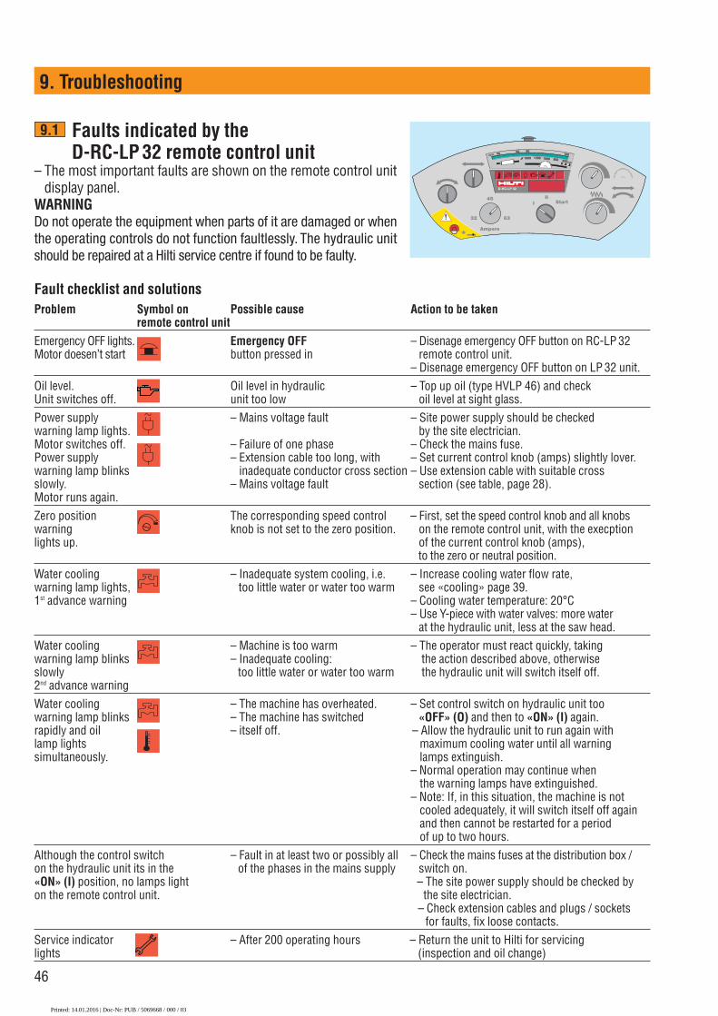
Faults indicated by the D-RC-LP 32 remote control unit
– The most important faults are shown on the remote control unitdisplay panel.
WARNINGDo not operate the equipment when parts of it are damaged or whenthe operating controls do not function faultlessly. The hydraulic unitshould be repaired at a Hilti service centre if found to be faulty.
Fault checklist and solutionsProblem Symbol on Possible cause Action to be taken
remote control unitEmergency OFF lights. Emergency OFF – Disenage emergency OFF button on RC-LP 32 Motor doesen’t start button pressed in remote control unit.
– Disenage emergency OFF button on LP 32 unit.Oil level. Oil level in hydraulic – Top up oil (type HVLP 46) and checkUnit switches off. unit too low oil level at sight glass.Power supply – Mains voltage fault – Site power supply should be checkedwarning lamp lights. by the site electrician.Motor switches off. – Failure of one phase – Check the mains fuse.Power supply – Extension cable too long, with – Set current control knob (amps) slightly lover. warning lamp blinks inadequate conductor cross section – Use extension cable with suitable crossslowly. – Mains voltage fault section (see table, page 28).Motor runs again.Zero position The corresponding speed control – First, set the speed control knob and all knobswarning knob is not set to the zero position. on the remote control unit, with the execptionlights up. of the current control knob (amps),
to the zero or neutral position.Water cooling – Inadequate system cooling, i.e. – Increase cooling water flow rate, warning lamp lights, too little water or water too warm see «cooling» page 39.1st advance warning – Cooling water temperature: 20°C
– Use Y-piece with water valves: more water at the hydraulic unit, less at the saw head.
Water cooling – Machine is too warm – The operator must react quickly, takingwarning lamp blinks – Inadequate cooling: the action described above, otherwiseslowly too little water or water too warm the hydraulic unit will switch itself off.2nd advance warningWater cooling – The machine has overheated. – Set control switch on hydraulic unit too warning lamp blinks – The machine has switched «OFF» (O) and then to «ON» (I) again.rapidly and oil – itself off. – Allow the hydraulic unit to run again with lamp lights maximum cooling water until all warning simultaneously. lamps extinguish.
– Normal operation may continue whenthe warning lamps have extinguished.
– Note: If, in this situation, the machine is notcooled adequately, it will switch itself off againand then cannot be restarted for a periodof up to two hours.
Although the control switch – Fault in at least two or possibly all – Check the mains fuses at the distribution box /on the hydraulic unit its in the of the phases in the mains supply switch on.«ON» (I) position, no lamps light – The site power supply should be checked byon the remote control unit. the site electrician.
– Check extension cables and plugs / socketsfor faults, fix loose contacts.
Service indicator – After 200 operating hours – Return the unit to Hilti for servicinglights (inspection and oil change)
9.1
D-RC-LP 32
Start
Ampere
III
32 63
45
1001600 1200 1000 900 800mm
806040
Printed: 14.01.2016 | Doc-Nr: PUB / 5069668 / 000 / 03

47
9. Troubleshooting
Error messages – "ER"
The following error messages are shown on the operating hours display on the RC-LP 32 remote controlunit:
Remote control unit errors Possible cause Action to be taken
Er00 RC-TS 5-E is connected instead of RC-LP32 Connect RC-LP32 remote control unit
Er01 No communication between the LP32 and RC-LP32 Contact Hilti service
Er02 No communication between the LP32 and RC-LP32 Contact Hilti service
Er03 Supply voltage from D-LP 32 hydraulic unit Contact Hilti serviceto remote control unit is less than 22 volts.
Hydraulic unit errors Possible cause Action to be taken
Er11 Processor error Contact Hilti service
Er12 Processor error Contact Hilti service
Er13 Error from left contactor Contact Hilti service
Er14 Error from right contactor Contact Hilti service
Er15 Error from star contactor Contact Hilti service
Er16 Error from delta contactor Contact Hilti service
Er17 Processor error Contact Hilti service
Er18 Processor error Contact Hilti service
Er21 Error from proportional valve Contact Hilti service
Er22 Error from service Contact Hilti service
Er23 Error from two-way pivot movement valve Contact Hilti service
Er24 Error from two-way valve Contact Hilti service
P000 or P999 The pressure sensor is defective. Contact Hilti serviceControl function is unsatisfactory.
9.2
Printed: 14.01.2016 | Doc-Nr: PUB / 5069668 / 000 / 03

48
9. Troubleshooting
Other malfunctions, hydraulic unit faults
Problem Possible cause Action to be taken
LP 32 starts but – Hydraulic couplings not fully – Check the hydraulic hoses, the saw head connected. check and engage couplings.doesn’t react – The belt drive from the electric – Unscrew bottom cover, check or doesn’t react correctly motor to the pump is defective. drive belt and replace it if
necessary (Hilti specialist).
LP 32 starts but – Electro-hydraulic valve(s) – Unscrew LP 32 front cover the saw head sticking (Hilti spezialist)doesn’t react – Check the electric plug or doesn’t react correctly. connections to the three valves.
– Check / move the slider. It maybe sticking due to dirt or corrosion.
Oil leaks from hydraulic – Oil escapes at the oil level sight – Check the oil level at the sight glass.unit. glass / vent tube. – Oil level too high or LP 32 standing
or hanging at an angle.– Reduce blade motor speed
(r.p.m.) slowly and switch off.
Water in oil, visible – Oil seals in saw head – Check at the vent or bywhen oil (at sight glass) defective opening the oil drainage screw.has milky-white – Oil cooler defective → Oil clear = OKappearance. – Hydraulic unit not drained at → Oil white = DANGER – unit
temperatures below zero must be servised immediately.
Water or oil leakage – Water seal defective – With the saw blade stationary, at the saw – Oil seal defective allow cooling water to flow. No arm drive flange water should run out of the small
bore.– If water runs out, the water seal
is defective. Return the saw head for servicing.
No power from the – 230 V supply has been – Press the reset button beside 230 V socket overloaded. Trip switch at "OFF". the socket, trip switch in "ON"
position. Total rating of appliances connected must not exceed 10 amps.
9.3
max Öl warm
max Öl kalt
min Öl kalt
max. oil warm
max. oil cold
min. oil cold
Printed: 14.01.2016 | Doc-Nr: PUB / 5069668 / 000 / 03

49
9. Troubleshooting
Hydraulic unit or saw system overheats / lacks power
Problem Possible cause Action to be taken
Saw system overheats: – Water supply inadequate, – Water flow rate at least 7 l/min.→ Too hot to touch water too warm – Increase water flow rate >7 ltr./min.→ Steam rises from – The water should be cool
saw head (tap water < 20° C)→ Drop in sawing – Saw blade not cutting, – Water supply hose must be connected
performance segments are polished to lower nipple on the hydraulic unit.– Sharpen the saw blade
→ Use a sharpening plate→ Alternatively, make a cut in abbrasive
brick or concrete with very little water.
LP/TS 32 – Cam-action rollers too tight – Adjust cam-action rollers: Set saw system levers to correct tension without play. → Overheats – Cam-action rollers too lose – Mount the rails securely. → Sawing performance – Play at saw head causes blade See page 29.
drops to wander – Do not overload the saw blade. → Saw blade wanders – Saw blade overloaded, too soft, Saw at a reasonable cutting depth.
off course blade takes on blue color – When cutting at great depth – Signs of friction / scoring on ≥60 cm (blade diameters 1500 /
sides of blade 1600 mm), make guide cut using – Cutting too deep 800 mm dia. blade with 5 mm
wide segments.– Select the correct saw blade
specification (for high power).– Saw blade motor speed too – Run at recommended speed or
high oil flow rate (see table on page 39).– Very high steel reinforcement – Reduce load (advance) slightly
content, very hard concrete or from time to time or allow blade hard aggregates to cool by running at low speed
without load for 2-3 minutes.
– Unsuitable saw blade – See page 15 of operating instructionsfor recommended saw blades
Operator – Saw blade running at too high – Observe recommended oil flow ratespeed = Observe recommended r.p.m.
See guide values on page 39.
9.4
4 mm
6 mm
Printed: 14.01.2016 | Doc-Nr: PUB / 5069668 / 000 / 03

50
10. Disposal of the D-LP32/DS-TS32 hydraulic saw system
Most of the materials from which Hilti electric tools are manufactured can be recycled. The materials must becorrectly separated before they can be recycled. In many countries, Hilti has already made arrangements for tak-ing back your old electric tools for recycling. Please ask your Hilti customer service department or Hilti repre-sentative for further information.
Only for EU countries
Disposal of electric tools together with household waste is not permissible!
In observance of European Directive on waste electrical and electronic equipment and its imple-mentation in accordance with national law, electric tools that have reached the end of their life mustbe collected separately and returned to an environmentally compatible recycling facility.
Printed: 14.01.2016 | Doc-Nr: PUB / 5069668 / 000 / 03

51
11. Manufacturer's warranty – tools
Please contact your local Hilti representative if you havequestions about the warranty conditions.
Printed: 14.01.2016 | Doc-Nr: PUB / 5069668 / 000 / 03

52
12. Declaration of conformity (original)
EC declaration of conformity (original)
Description Hydraulic saw systemSerial numbers Up to 9999Designation D-LP 32/DS-TS 32Year of design 2001
We declare under our sole responsibility that this product complies with the following directives and standardsuntil 19th April 2016: 2004/108/EC, from 20th April 2016: 2014/30/EU, 2006/42/EC, 2011/65/EU, EN 60204‑1,EN 12100.
Technical documentation filed at:Hilti Entwicklungsgesellschaft mbHZulassung ElektrowerkzeugeHiltistrasse 686916 KauferingDeutschland
Hilti Corporation, Feldkircherstrasse 100, FL-9494 Schaan
Paolo Luccini Johannes Wilfried HuberHead of BA Quality and Process Management Senior Vice PresidentBusiness Area Electric Tools & Accessories Business Unit Diamond
06 / 2015 06 / 2015
Printed: 14.01.2016 | Doc-Nr: PUB / 5069668 / 000 / 03

53
Printed: 14.01.2016 | Doc-Nr: PUB / 5069668 / 000 / 03

54
Printed: 14.01.2016 | Doc-Nr: PUB / 5069668 / 000 / 03

55
Printed: 14.01.2016 | Doc-Nr: PUB / 5069668 / 000 / 03

*370698*
3706
98
Hilti Corporation LI-9494 SchaanTel.: +423 / 234 21 11Fax:+423 / 234 29 65www.hilti.com
Hilti = registered trademark of Hilti Corp., Schaan en | 20150922
Printed: 14.01.2016 | Doc-Nr: PUB / 5069668 / 000 / 03