d o u b l e eccentr ic m co p et n e in actuat butt erfly
TRANSCRIPT

Double Eccentric Butterfly Valve
competence in actuators, valves and more
www.airpower-gmbh.com
SERI
ES 3
5
2
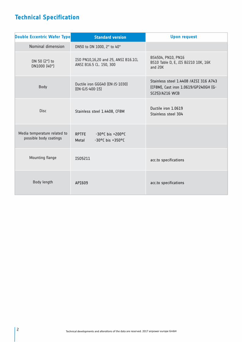
Technical Specification
Nominal dimension
DN 50 (2“) to DN1000 (40“)
Body
Disc
Media temperature related to possible body coatings
Mounting flange
Body length
Upon request
BS4504, PN10, PN16BS10 Table D, E, JIS B2210 10K, 16K and 20K
Stainless steel 1.4408 /AISI 316 A743
(CF8M), Cast iron 1.0619/GP240GH (G-
SC25)/A216 WCB
Ductile iron 1.0619
Stainless steel 304
acc.to specifications
acc.to specifications
Standard version
DN50 to DN 1000, 2“ to 40“
ISO PN10,16,20 and 25, ANSI B16.1CLANSI B16.5 CL. 150, 300
Ductile iron GGG40 (EN-JS-1030)(EN-GJS-400-15)
Stainless steel 1.4408, CF8M
RPTFE -30°C bis +200°C
Metal -30°C bis +350°C
ISO5211
API609
Double Eccentric Wafer Type
Technical developments and alterati ons of the data are reserved. 2017 airpower europe GmbH

15
14
13
12
7
11 5 4 3
7
9
10
2
1
6
8
Part description
Pos.-No.
1
2
3
4
5
6
7
8
9
10
11
12
13
14
15
Description
Body
Seat retainer ring
Disc
Bolt
Seal
V-type ring sealing
Bearing bush
Stem sealing
Stem sealing
Cover
Screws
Upper seal
Gland
Screws
Bridge
3
Technical developments and alterati ons of the data are reserved. 2017 airpower europe GmbH

Setup of Series 35, DN50 (2“) – DN 1000 (40“)
1 Top flange acc. to ISO-5211.
2 Maintenance-free bearing for all nominal sizes. Bearing for exact centering of the disc. Valve disc double eccentric mounted.
3 All sealing surfaces are machined. As an advantage you have low torque and low wear.
4The bolt is secured by a locking plate. An additional sealing ring ensures that the inner area of the bolt is protected against dirt and liquids.
5The seat ring inserted with a positive fit ensures absolute tightness and compensates for wear. Replacement is possible without disas-sembly of shaft and disc.
6 The removable retainer ring protects against abrasion and erosion.
7 The continuous shaft ensures high stability.
1
6
7
2
3
45
4 Technical developments and alterati ons of the data are reserved. 2017 airpower europe GmbH
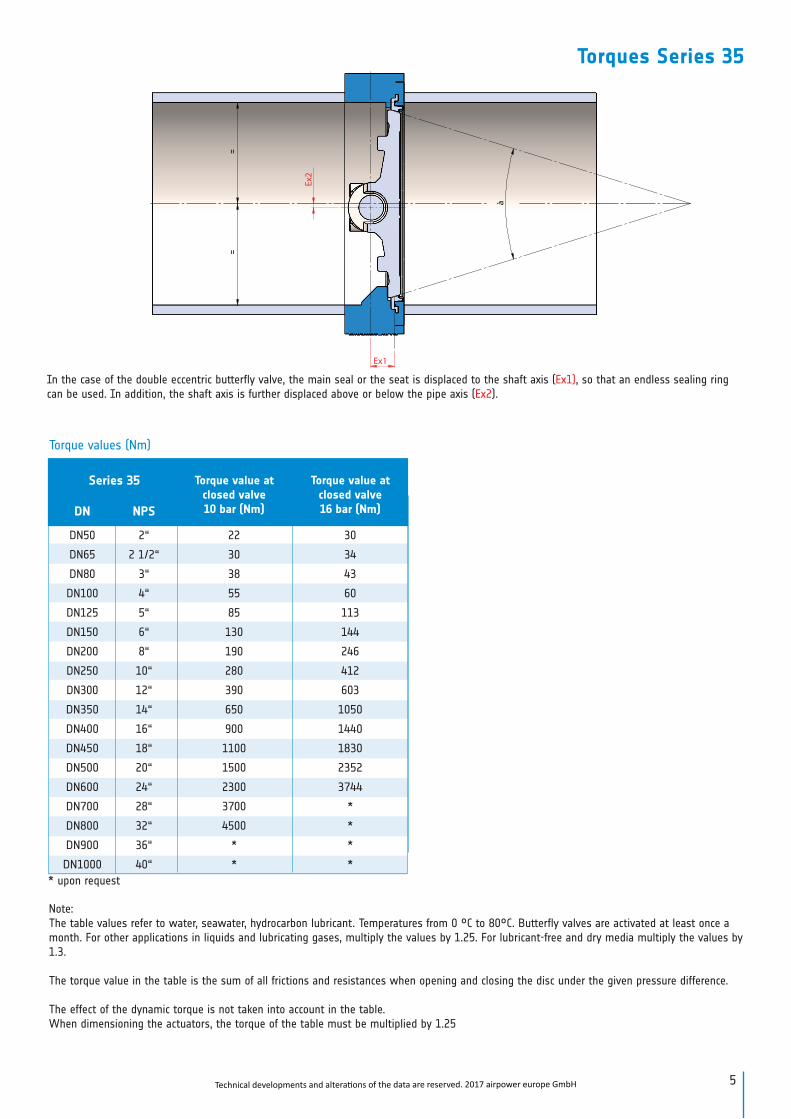
Torque values (Nm)
Note:The table values refer to water, seawater, hydrocarbon lubricant. Temperatures from 0 °C to 80°C. Butterfly valves are activated at least once a month. For other applications in liquids and lubricating gases, multiply the values by 1.25. For lubricant-free and dry media multiply the values by 1.3.
The torque value in the table is the sum of all frictions and resistances when opening and closing the disc under the given pressure difference.
The effect of the dynamic torque is not taken into account in the table.When dimensioning the actuators, the torque of the table must be multiplied by 1.25
Torques Series 35
Series 35 Torque value at closed valve 10 bar (Nm)
Torque value at closed valve 16 bar (Nm)DN NPS
DN50 2“ 22 30
DN65 2 1/2“ 30 34
DN80 3“ 38 43
DN100 4“ 55 60
DN125 5“ 85 113
DN150 6“ 130 144
DN200 8“ 190 246
DN250 10“ 280 412
DN300 12“ 390 603
DN350 14“ 650 1050
DN400 16“ 900 1440
DN450 18“ 1100 1830
DN500 20“ 1500 2352
DN600 24“ 2300 3744
DN700 28“ 3700 *
DN800 32“ 4500 *
DN900 36“ * *
DN1000 40“ * *
à
Ex1
Ex2
In the case of the double eccentric butterfly valve, the main seal or the seat is displaced to the shaft axis (Ex1), so that an endless sealing ring can be used. In addition, the shaft axis is further displaced above or below the pipe axis (Ex2).
* upon request
5Technical developments and alterati ons of the data are reserved. 2017 airpower europe GmbH

Size A B C D øE øF / ISOWeight/
KG
50 76 150 13,5 43 11 4x ø7 ø50 / F05 3,2
65 81 162 13,5 46 11 4x ø7 ø50 / F05 5
80 128 1740 17,5 46 14 4x ø8 ø70 / F07 6
100 130 192 17,5 52 14 4x ø8 ø70 / F07 8
125 145 209 20,5 56 17 4x ø8 ø70 / F07 12
150 146 215 20,5 56 17 4x ø8 ø70 / F07 13,8
200 184 300 25,5 60 22 4x ø11 ø102 / F10 23,1
250 228 320 25,5 68 22 4x ø11 ø102 / F10 30,7
300 245 350 30,5 78 27 4x ø13 ø125 / F12 42,8
350 275 360 30,5 78 27 4x ø13 ø125 / F12 60,4
400 326 440 39 102 36 4x ø17 ø140 / F14 106,7
450 350 500 39 114 36 4x ø17 ø140 / F14 130,4
500 395 530 49 127 46 4x ø17 ø140 / F14 167
600 468 590 49 154 46 4x ø21 ø165 / F16 302
700 550 660 60 165 55 8x ø17 ø254 / F25 364
800 585 750 60 190 55 8x ø21 ø298 / F30 494
900 643 790 * 203 75/55 8x ø21 ø298 / F30 638
1000 726 890 * 216 75 8x ø21 ø298 / F30 888
A
B
DN
C
D
E
F
* upon request
Dimensions wafer type Series 35 DN50 (2“) to DN 1000 (40“) with bare shaft
6 Technical developments and alterations of the data are reserved. 2017 airpower europe GmbH

Size A B C D øE F
Weight/KG
DN50 76 150 99 48 100 43 4,7
DN65 81 162 99 48 100 46 7
DN80 128 1740 115 54 120 46 7,9
DN100 130 192 115 54 120 52 9,9
DN125 145 209 115 54 120 56 11,9
DN150 146 215 115 54 120 56 15,7
DN200 184 300 220 71 300 60 28,3
DN250 228 320 220 71 300 68 35,9
DN300 245 350 208 72 300 78 53,8
DN350 275 360 208 72 300 78 71,4
DN400 326 440 287 81 400 102 127,3
DN450 350 500 287 81 400 114 151,4
DN500 395 530 357 91 500 127 199
DN600 468 590 382 93 500 154 346
DN700 550 660 448 130 500 165 430
DN800 585 750 480 160 500 190 603
DN900 643 790 555 160 600 203 760
DN1000 726 890 555 160 600 216 1010
E
F DN
A
B
D
C
Dimensions wafer type Series 35 DN50 (2“) to DN1000 (40“) with gearboxiebe
7Technical developments and alterations of the data are reserved. 2017 airpower europe GmbH
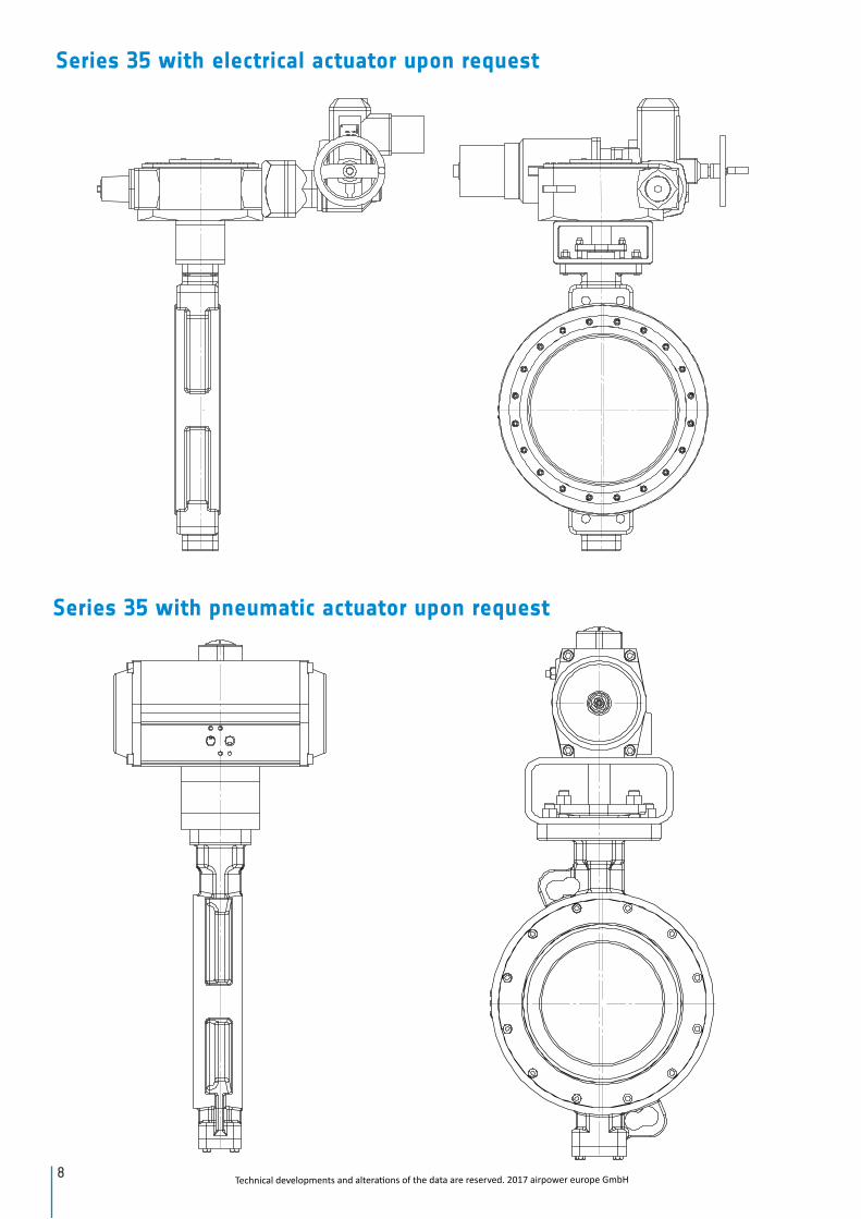
Series 35 with electrical actuator upon request
8
Series 35 with pneumatic actuator upon request
Technical developments and alterations of the data are reserved. 2017 airpower europe GmbH
0° basic position90° switch position
0° basic position90° switch position
0° basic position90° switch position
0° basic position90° switch position
Technical developments and alterati ons of the data are reserved. 2017 airpower europe GmbH 9
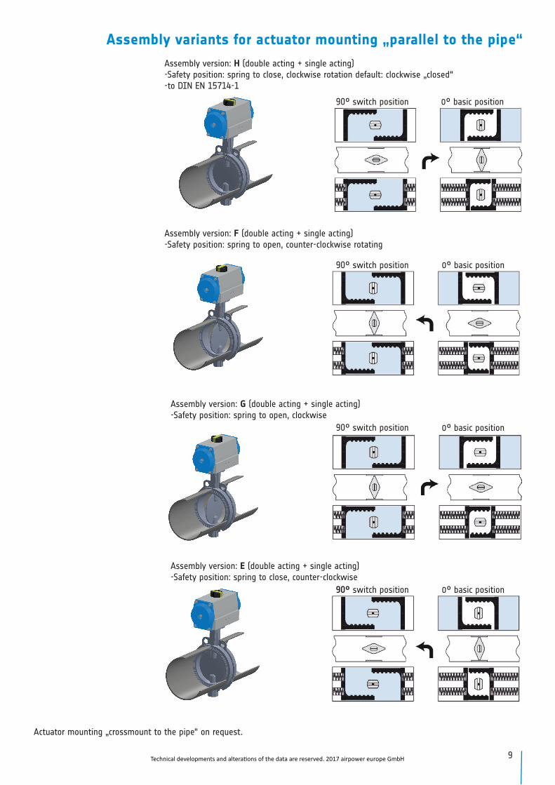
Assembly version: H (double acting + single acting)-Safety position: spring to close, clockwise rotation default: clockwise „closed“ -to DIN EN 15714-1
Assembly version: F (double acting + single acting)-Safety position: spring to open, counter-clockwise rotating
Assembly version: G (double acting + single acting)-Safety position: spring to open, clockwise
Assembly version: E (double acting + single acting)-Safety position: spring to close, counter-clockwise
Assembly variants for actuator mounting „parallel to the pipe“
Actuator mounting „crossmount to the pipe“ on request.

10 Technical developments and alterati ons of the data are reserved. 2017 airpower europe GmbH
Service hotline for questions and information:
+49 (0) 22 24 / 98 83 20
Order code
Order examples for a double eccentric butterfly valve DN150 with bare shaft
F W D – 35 150 – F10 V22FF C D B E A 0Type of actingF = Free shaft H= Hand lever/gearboxP= pneum. Actuator, E= Electric actuator
Valve typeW= Wafer
D= Standard Butterfly valve
– – – – – – – –
Valve typeSeries 35= Double eccentric butterly valve
Nominal dimension of valveDimension=DN50 –DN1000
Body materialF= Cast iron 1.0619/GP240GH (G-SC25) / A216 WCB
Disc materialC= Stainless steel 1.4408 /ASTM 316 A743 /CF8M / AISI 316
Body coatingD=PTFE -30°C to +160°C
Stem materialB= 1.4542 (17-4PH) AISI 630 / ASTM A564M-13
Pressure ratingF= ANSI CL 150
Delta-pE= 10/16bar and ANSI CL 150
Overall lengthA= DIN EN 558-1 range 20 (series 23 and 24) K1
Interface/square shaftF10 = DIN EN 5211/ V22
Assembly0= No assemblyFor assembly refer to separate order code
1 2 3 4 5 6 7 8 9 10 11 12 13 14
1
2
3
4
5
6
7
8
9
10
11
12
14
13

Notes
11Technical developments and alterations of the data are reserved. 2017 airpower europe GmbH
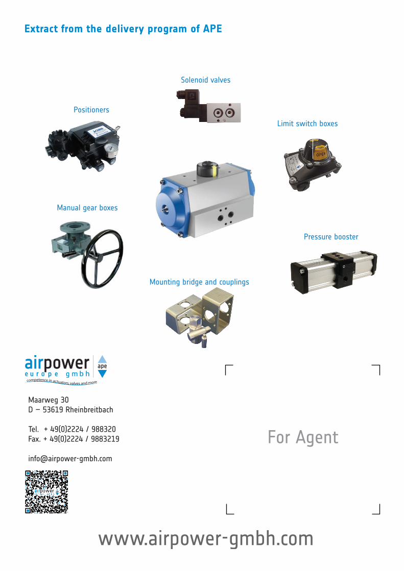
Extract from the delivery program of APE
competence in actuators, valves and more
Maarweg 30D – 53619 Rheinbreitbach
Tel. + 49(0)2224 / 988320Fax. + 49(0)2224 / 9883219
Pressure booster
Manual gear boxes
Solenoid valves
Mounting bridge and couplings
Limit switch boxes
Positioners
For Agent
www.airpower-gmbh.com