d-ts-v1019 2 prunew - abb group · for practical reasons we recommend a maximum long- ......
TRANSCRIPT

Data SheetD-TS-V1019_2
Sanitary Temperature Measurement Products 3A Approved Spring Loaded Sensor Assembly - V10196
3A Approved Sensor Assembly w/o Thermowell - V10198
Sanitary Spring LoadedSensor Assembly -V10196
Sanitary Sensor Assemblyw/o Thermowell - V10198
Design- Can be built from standardized components- Standard lengths for fewer spare parts on stock- Immersion lengths can be selected individually- Sensor can be replaced during operation- No welding seams coming into contact with
media
Technical features- Approvals according to FM and ATEX for
intrinsically safe installation of thetransmitter
- Thermowell construction designed speciallyfor food and dairy applications
- Installation of a transmitter in theconnection head eliminates the need formulti-wire circuit
- Interference-immune standard output signal4 to 20 mA
Applications- Food and Dairy- Beverage- Pharmaceutical- Chemical- Cosmetics

2
Temperature Measurement Products3A Approved Sanitary Sensors D-TS-V1019_2
Sensor Design
The CIP (clean in place) 3A approved sanitarysensors(V10198) are specially designed for use in thefood,dairy, beverage, pharmaceutical, chemical andcosmetic industries. The sensors are polished to a No.4finish, required by the 3A Council Standard #74-00. Thisfinish assures there are no pits or crevices. The tri-clampfitting(figure 2) is the most common sanitary sensor.Others, such as the Cherry-Burrell and Alloy Productsare available. Reduced tip sensors can also be re-quested.
A standard thermocouple or RTD sensor can also beused with a sanitary thermowell. This sensor design isideal for mating the sensors to virtually any enclosureand assembly. The sensors:
- can be removed while the system isrunning without dismantling the entiresensor assembly
- can be calibrated in a standard facility- can be stocked as a universal standard
component in order to assure availability ofthe system during replacement
3A Approved Sanitary Sensor AssemblyV10198
3A Approved Sanitary Spring Loaded Sensor AssemblyV10196
Figure 1
Figure 2
R

3
Temperature Measurement Products3A Approved Sanitary Sensors D-TS-V1019_2
Response times
Apart from the thermowell mass at the measuring point,the factors governing the heat transfers, which are thechief determinants for the response time, are the heatcapacity, pressure, density, moisture and flow velocity ofthe medium. The following table features approximatevalues, based on a step change from room temperatureto boiling water.
Table 1 indicates time to show 63.2% of a temperaturechange. This data can be used as a means of comparingsheath size and junction only. RTD’s usually match thesame size ungrounded thermocouple.
Resistance Temperature Detectors (RTD)
Nominal resistance/Standard/Tolerance
Resistance elements with platinum measurementwindings are used. In accordance with DIN EN 60 751the nominal resistance is defined as follows:
• 100 ohms at 0 °C
• Temperature coefficient 3.85 x 10 -3 (K -1) - Averaged between 0 °C and 100 °C.
For your quick reference some typical permissible valuesare shown in the table below for Class A and B.For practical reasons we recommend a maximum long-term operating temperature of max. 400 °C for Class Atolerance.
Operational temperature
The temperature range is from -392 to +1110ºF (-200 to +600°C)
Sheath material
The standard material used for all resistancethermometer measuring sensors is 316 StainlessSteel.
Number of lead wires/measuringcircuits/sheath diameters
Sensors can be supplied with:• 1 or 2 measurement RTD’s and in 2, 3 and 4-wire circuits.
However, in some particular cases the combinationsare restricted.
Table 1
Sheath O.D. Measuring Junction
Response Time (seconds)
.040(1/25”) Grounded 0.07Ungrounded 0.11
.063(1/16”) Grounded 0.09Ungrounded 0.28
.125(1/8”) Grounded 0.34Ungrounded 1.6
.188(3/16”) Grounded 0.7Ungrounded 0.26
.250(1/4”) Grounded 1.7Ungrounded 4.5
Table 2
Temperature 0ºC/32ºF 100ºC/212ºF 200ºC/392ºF 300ºC/572ºF 400ºC/852ºF 500ºC/932ºF 600ºC/1112ºF
Ω 100 138.51 175.86 212.05 247.09 280.98 313.71
Class B 0.3ºC/2.1ºF 0.8ºC/2.6ºF 1.3ºC/3.1ºF 1.8ºC/3.6ºF 2.3ºC/4.1ºF 2.8ºC/4.6ºF 3.3ºC/5.1ºF
Class A 0.15ºC/1.95ºF 0.35ºC/2.15ºF 0.55ºC/2.35ºF 0.75ºC/2.55ºF 0.95ºC/2.75ºF 1.15ºC/2.95ºF N/A
Resistance of platinum RTD according to IEC 60 751
Allowed Deviation for platinum RTD according to IEC 60 751

4
Temperature Measurement Products3A Approved Sanitary Sensors D-TS-V1019_2
Thermocouples
Standard/ToleranceFor thermocouples conforming to DIN EN 60 584 variousdifferent classes are defined for the permissible deviationfrom the e.m.f. reference table. The measured thermo-electric emf. corresponds to the temperature differencebetween hot junction and reference junction. Thereference table conforming to DIN EN 60 584 relates toa reference temperature at 0 °C. Because of the factthat, as the temperature rises, the effects of oxidationcan have significant adverse effects on the characteris-tics and service life of a measuring inset, the specifiedoperating temperatures (dependent on thermocoupletype, tolerance class and sheath diameter) should neverbe exceeded.
Accessories, componentsMany of the components of the models listed in thecatalog can be ordered as separate components ormodules. In this respect, please consult your nearestrepresentative.
Resistance vs. Temperature Tables
The condensed Resistance VS Temperature Tables onthe following pages are provided to aid in the proper RTDelement selection.
Notice that the tables for the various platinum curves arefor the standard 100 ohm @ 0ºC sensor.
To calculate the resistance of:
50 ohm multiply the values by .5200 ohm multiply the values by 2500 ohm multiply the values by 5100 ohm multiply the values by 10
Table C100 for the 100 ohm @ 25ºC Copper (90.35ohms @ 0ºC) is published. To calculate theresistance of the 10 ohm at 25ºC (9.035 ohms @ 0ºC)multiply the value shown by .1.
Table 3
TEMP. TEMP.ºC -100 0 ºC 0 100 200 300 400 500 6000 60.25 100 0 100 138.5 175.84 212.03 247.06 280.9 313.59
-10 56.19 96.09 10 103.9 142.29 179.51 215.58 250.5 284.22 316.8-20 52.11 92.16 20 107.79 146.06 183.17 219.13 253.93 287.53 319.99-30 48 88.22 30 111.67 149.82 185.82 222.65 257.32 290.83 323.18-40 43.67 84.27 40 115.54 153.58 190.46 226.18 270.72 294.11 326.35-50 39.71 80.31 50 119.4 157.32 194.08 229.69 264.11 297.39 329.51-60 35.53 76.33 60 123.24 161.04 197.69 233.19 267.49 300.65 332.66-70 31.32 72.33 70 127.07 164.76 201.3 236.67 270.86 303.91 335.79-80 27.08 68.33 80 130.89 168.47 204.88 240.15 274.22 307.15 338.92-90 22.8 64.3 90 134.7 172.16 288.46 243.61 277.56 310.38 342.03-100 18.49 60.25 100 183.5 175.84 212.03 247.05 280.9 313.59 345.13
100 Ω PLATIMUM (.00385 Ω/Ω/ ºC) @ 0ºC(DIN 43760)
5
Temperature Measurement Products3A Approved Sanitary Sensors D-TS-V1019_2
Other versionsThis data sheet contains only a small selection of ourrange of thermometers with thermowells and transmitter.Please consult your nearest representative for othermodels.
Other options:- Special Insertion Length- Special process connection- Thermowell material- Design style of thermowell- Conduit connections- Connection head painting- Tests and certificate
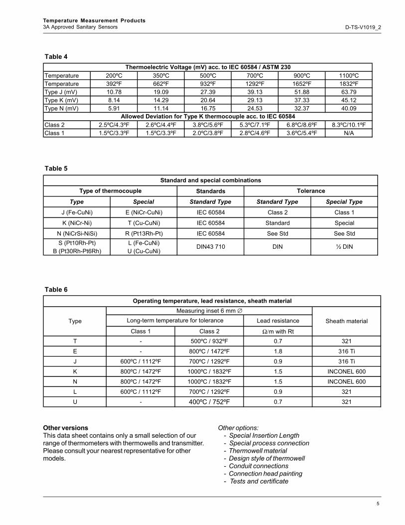
Table 4
Temperature 200ºC 350ºC 500ºC 700ºC 900ºC 1100ºCTemperature 392ºF 662ºF 932ºF 1292ºF 1652ºF 1832ºFType J (mV) 10.78 19.09 27.39 39.13 51.88 63.79Type K (mV) 8.14 14.29 20.64 29.13 37.33 45.12Type N (mV) 5.91 11.14 16.75 24.53 32.37 40.09
Class 2 2.5ºC/4.3ºF 2.6ºC/4.4ºF 3.8ºC/5.6ºF 5.3ºC/7.1ºF 6.8ºC/8.6ºF 8.3ºC/10.1ºFClass 1 1.5ºC/3.3ºF 1.5ºC/3.3ºF 2.0ºC/3.8ºF 2.8ºC/4.6ºF 3.6ºC/5.4ºF N/A
Thermoelectric Voltage (mV) acc. to IEC 60584 / ASTM 230
Allowed Deviation for Type K thermocouple acc. to IEC 60584
Table 5
Standards
Type Special Standard Type Standard Type Special Type
J (Fe-CuNi) E (NiCr-CuNi) IEC 60584 Class 2 Class 1
K (NiCr-Ni) T (Cu-CuNi) IEC 60584 Standard Special
N (NiCrSi-NiSi) R (Pt13Rh-Pt) IEC 60584 See Std See StdS (Pt10Rh-Pt) L (Fe-CuNi)
B (Pt30Rh-Pt6Rh) U (Cu-CuNi)
Standard and special combinations
Type of thermocouple Tolerance
DIN43 710 DIN ½ DIN
Table 6
Lead resistance
Class 1 Class 2 Ω/m with RtT - 500ºC / 932ºF 0.7 321
E - 800ºC / 1472ºF 1.8 316 Ti
J 600ºC / 1112ºF 700ºC / 1292ºF 0.9 316 Ti
K 800ºC / 1472ºF 1000ºC / 1832ºF 1.5 INCONEL 600
N 800ºC / 1472ºF 1000ºC / 1832ºF 1.5 INCONEL 600
L 600ºC / 1112ºF 700ºC / 1292ºF 0.9 321
U - 400ºC / 752ºF 0.7 321
Operating temperature, lead resistance, sheath material
Type
Measuring inset 6 mm ∅
Sheath materialLong-term temperature for tolerance

6
Temperature Measurement Products3A Approved Sanitary Sensors D-TS-V1019_2
TEMPERATURE - MILLIVOLT CURVES
0
10
20
30
40
50
60
70
32 1000 2000 3000DEGREES FAHRENHEIT
MIL
LIVO
LTS
(APP
RO
X.)
TYPE E
TYPE J
TYPE K
TYPE RTYPE S
TYPE B
TYPE T
Figure 3
Limit of ErrorReference Junction at 32ºF
Table 7
-200 to 350ºC ± 1ºC or 0.759% above 0ºC ± .5ºC-328 to 852ºF ± 2ºF or 1.5º below 0ºC ± 1ºC=F
0 to 750ºC ± 2.2ºC ± 1.1ºC32 to 1382ºF ± 4ºF ± 2ºF-200 to 900ºC ± 1.7ºC or 0.5% above 0ºC ± 1ºC-328 to 1652ºF ± 3ºF or 1.0% below 0ºC ± 2ºF-200 to 1250ºC ±2.2ºC or 0.75% above 0ºC ± 1.1ºC-328 to 2282ºF ± 4ºF or 2.0% below 0ºC ± 2ºF400 to 1400ºC ±1.5ºC752 to 2550ºF ± 3ºF800 to 1800ºC ±0.5%1475 to 3270ºF over 900ºC (1470ºF)
0 to 1250ºC ±2.2ºC or 0.75% above 0ºC ± 1.1ºC32 to 2282ºF ± 4.0ºF or 2.0% below 0ºC ± 2ºF
N or ± .4%
When the limit of error is given in %, the percentage applies to the temperature being measured, not the range.
Temperature RangeThermocouple Calibration
R, S or ± .25% Or ± .1%
B or ± .50% Or ± .25%
E or ± .4%
K or ± .4%
T or ± .4%
J or ± .75% or ± .4%
Limits of ErrorStandard
(Whichever is Greater)Special
(Whichever is Greater)

7
Temperature Measurement Products3A Approved Sanitary Sensors D-TS-V1019_2
Thermocouple Lead-Wire Configurations
Thermocouple Junction Configurations
Single, Grounded
Single, Ungrounded
Figure 4
Type J Type E+ Purple
- Red
+ Yellow
- Red
Type T+ Blue
- Red
+ ++
--
Dual, Grounded, Unisolated
-
++
--
Dual, Ungrounded, Unisolated
++
--
Dual, Ungrounded, Isolated
•
•
+ White
- Red
•
Type K
•
• •
+
••
• •
8
Temperature Measurement Products3A Approved Sanitary Sensors D-TS-V1019_2
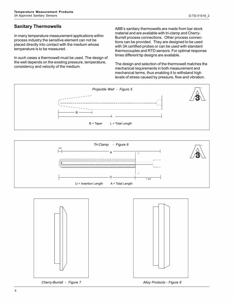
Sanitary Thermowells
In many temperature measurement applications withinprocess industry the sensitive element can not beplaced directly into contact with the medium whosetemperature is to be measured.
In such cases a thermowell must be used. The design ofthe well depends on the existing pressure, temperature,consistency and velocity of the medium.
ABB’s sanitary thermowells are made from bar stockmaterial and are available with tri-clamp and Cherry-Burrell process connections. Other process connec-tions can be provided. They are designed to be usedwith 3A certified probes or can be used with standardthermocouples and RTD sensors. For optimal responsetimes different tip designs are available.
The design and selection of the thermowell matches themechanical requirements in both measurement andmechanical terms, thus enabling it to withstand highlevels of stress caused by pressure, flow and vibration.
Tri-Clamp - Figure 6
Cherry-Burrell - Figure 7 Alloy Products - Figure 8
U = Insertion Length A = Total Length
1/4”
A
U1 3/4”
B = Taper L = Total Length
LB
Projectile Well - Figure 5
R
R

9
Temperature Measurement Products3A Approved Sanitary Sensors D-TS-V1019_2
Material options
- 304 and 304/L Stainless Steel- 316 and 316/L Stainless Steel- Inconel 600
All thermowells in this data sheet are drilled from barstock material and their outside shape machined. Thethermowell designs represent common modelsconforming to 3A sanitary standards. Custom designedthermowells can also be supplied to any specification.All sanitary thermowells are polished to a #4 finish tomeet 3A approval.
Operational data
The permissible stress depends on medium andinstallation related data:
General application specifications cannot be given inview of the wide range of choices. If stress values areneeded, a Murdock or Dittrich stress analysis test isrecommended.
Medium related Installation related- Medium - Material- Viscosity - Thermowell design- Flow velocity - Immersion length- Pressure - Pressure at process connection- Temperature - Vibration
How to Select Thermowells
Thermowells are used to shield thermocouple elementsagainst mechanical damage and corrosion. Manyvariations are available in a variety of materials to meetindividual job specifications.
The chemical and physical properties of all standard barstock materials are rigidly controlled. Use of speciallydesigned and constructed measuring equipment enablesstandard guaranteed bore concentricity to be within ±10% of wall thickness. Internal threads are within 1/2turn of standard plug gauge. External threads are within1/4 turn of standard ring gauge.
If required by purchase order, your thermowells undergoan internal hydrostatic test as a final precaution againstpressure failure. Test pressures and duration aredetermined by the customer. Radiograph and othertests can be performed and results furnished uponrequest.
A variety of alloys suitable for every thermowell require-ment is available. Thermowell material should beselected for ability to withstand the process environ-ments, high thermal conductivity and low porosity togases.
Choosing Bore Sizes for Maximum Fexiblity
Where several types of temperature measuring instru-ments are used, the selection of a standard bore diam-eter can provide greater efficiency and flexibility of use.The same well can accommodate either thermocouple,resistance thermometer, bi-metal thermometer or testthermometer. The bore sizes of wells shown in thiscatalog accommodate the most commonly used tem-perature sensing elements. For example:
.260 Diameter Bore:
• Bi-Metal Thermometers (1/4” stem)• Thermocouples (#14 Awg)• RTD’s• Other elements having .252 max. O.D.

10
Temperature Measurement Products3A Approved Sanitary Sensors D-TS-V1019_2
When to Use Tapered or Straight Thermowells
Tapered thermowells provide greater strength withoutsacrificing sensitivity. Because of its higher strength-to-weight ratio, the tapered thermowell provides greaterresistance to high frequency vibrations than straightthermowells. This permits reliable operation at high fluidvelocities. Thus, for higher fluid velocities, the taperedwell should be chosen; for lower fluid velocities, thestraight well.
Choosing the Material
A most important factor in selecting thermowell materialis to determine the corrosive conditions to which the wellwill be exposed. The high mirror polish given to all wellsenhances its corrosion resistance capability.
Occasionally, the material consideration is one ofstrength rather than corrosion. For example, a stainlesssteel well may be required for high pressure waterservice, where a brass well might have been satisfactoryfrom a corrosion viewpoint.
Type B, Aluminum,epoxy painted
~ 1.97 (~ 50)
~2
.95
(~7
5)
0.6
7(1
7)
1.0
2(2
6)
M20x1,5
Figure 9
Figure 12For use with a prometer
or cometer
~ 2.95 (~ 75)
~5
.91
(~1
50
)
0.6
7(1
7)
1.6
1(4
1)
M20x1,5
Type Polypropylene
Figure 13
Type Stainless Steel
Figure 14To Come
Type AGL,Aluminum, epoxy painted
Figure 11
~2.95 (~ 75)
~4
.53
(~1
15
)
0.6
7(1
7)
1.6
1(4
1)
M20x1,5
Type BUZH,Aluminum, epoxy p.
Figure 10
~ 2.56 (~ 65)
~4
.33
(~1
10
)
0.6
7(1
7)
1.0
2(2
6)
M20x1,5
Picture notavailable at this
time
Type AGLHD, Aluminum,epoxy painted
Connection HeadsThere are several connection heads available:
Connection Head Types Material Cable Entry Degree of protection Lid closure Surface
B Aluminum ½” NPT NEMA 4 2 Screws Epoxy Painted
BUZH Aluminum ½” NPT NEMA 4 Hinged Epoxy Painted
AGL Aluminum ½” NPT NEMA 4X Screwed Lid Epoxy Painted
AGLHD Aluminum ½” NPT NEMA 4X Screwed Lid Epoxy Painted
3A Sanitary Polypropylene 3/4” NPT NEMA 4X Screwed Lid Smooth Finish
3A Sanitary Stainless Steel ½” NPT NEMA 4X Screwed Lid Smooth Finish

11
Temperature Measurement Products3A Approved Sanitary Sensors D-TS-V1019_2
Transmitter Options
General Purpose
TF02 Foundation FieldbusTF12 PROFIBUS PATH 02 HART® programmableTS04 Programmable via push
button. (2/3 wire RTD)TS05 Programmable via push
button (Type J & K TC)
Hazardous Areas (intrinsically safe)
TH 02-Ex HART® programmableTF 12-Ex PROFIBUS PATF 02-Ex Foundation Fieldbus
Figure 15Nipple - Union
Extension

12
Temperature Measurement Products3A Approved Sanitary Sensors D-TS-V1019_2
TH02/TH02-ex – Head-mounted temperaturetransmitter, HART programmable via push-button, Pt 100 (RTD), thermocouples, electri-cal isolation
Technical DataOutput
Output signal(temperature-linear) 4 to 20 mA
Current consumption <3.6 mAMax. output current 23.6 mAResidual ripple <0.3%
Parameterizable current error signalUnderranging 3.6 mAOverrranging 22 mADefault value 3.6 to 23.6 mA
Damping t63 = 0 to 30Input
ResistanceResistance
thermometer Pt 100(IEC751,JIS,SAMA)n - Pt 100/Ni 100 toPt 1000/ Ni 1000: Cu(n=0.1, 0.2, 0.5, 1, 2, 3, to
10)Min. measuring span
15K/50 KResistance 0 to 500 ohm/0 to 5000 ohm
Min.measuring span5 ohm/50 ohm
Maximum line resistance (Rw) per core2,3,4 wire 7.5 ohm, 10 ohm,
50 ohmMeasuring current 300 uA
Sensor short-circuit <5 ohm (for RTD)
Sensor break (temperature/resistancemeasurement 2,3,4 wire)Measuring range 0 to 500 ohm >530 ohmMeasuring range 0 to 5000 ohm >5.3 K ohm
Sensor wire break monitoring in accordancewith NAMUR NE 89Sensor wire break detection3 wire resistance measurement >35 ohm4 wire resistance measurement >3.7 K ohm
ThermocouplesVoltages -125 mV to +125 mV
-125 mV to +1200 mVMinimum measuring span 2 mV/50 mVSensor wire break monitoring in accordancewith NAMUR NE 89
Pulsed with 1 uA outside of the measuring intervalMonitoring disconnectibleThermocouple measurement > 5 k ohmVoltage measurement > 5 k ohmInternal reference junctionPt 100, via software switchable (no jumper necessary)
Power Supply (poling protected)Supply voltageNon-Ex-application Us = 8.5 to 30 V DCFor Ex-Application, max. Ui = 8.5 to 29.4 V DC2 wire method: power supply wires =
signal wiresInfluence of supply voltage <0.05 % / 10Maximum residual ripple < or = 1% Us
(<500 Hz)Power demand of indicators(only with AGL head)
(Power demand of transmitter and indicator have to be added)
Prometer and Cometer Usd = 2.9 V DCMaximum load (Usmax – Usmin)R(k ohm) = 23.6
General characteristicsOutput signal refreshment rate
Pt 100 0.4 s (Input signalchange < 0.25 K/s)
Thermocouples 0.2 s (Input signalchange < 0.25 K/s)
Vibration resistanceVibration in operation 2g acc. to
DIN IEC 68T. 2-6Resistance to shock acc. to
DIN IEC 68T.2-27Electrical isolation (I/O) 1.5 kV AC (60 s)Long-term stability < or = 0.1 % p.a.
Environment conditionsAmbient temperature range -40 to 85 dg. CTransport and storage
temperature -40 to 100 dg.CRelative humidity <100 %
(100% humidity withisolated terminalsonly)
Condensation Permitted

13
Temperature Measurement Products3A Approved Sanitary Sensors D-TS-V1019_2
Mechanical constructionDimension Refer to
dimensional drawingWeight 2 ouncesHousing material
PolycarbonateBlack (Non-Ex-type)Blue (Ex-type)
Electrical connectionTerminals , pluggable 2.5 mm 2. screw terminals
(stainless steel screws)
For more detail information of this temperature transmitter, refer to Data sheet D-TH-TH02/TH02-ex
Connection Diagram
Characteristics at rated conditionsAccording to IEC 770 (related to 25 dg. C) 1)
Digital measured errorPt 100 + or = 0.1 KThermocouples + or = 20uVLinear resistance 500 ohm / 5000 ohm
+ or = 40m ohm/200 m ohmLinear voltage 120 mV / 1200 mV
+ or = 20 uV / 50 uVD/A measured error + or = 0.05% of measuring
span1) Percentage related to set measuring span
Dimensional Diagram (dimensions in mm)
1
3
4
2
ϑ4...20 mA
+
-
1
3
4
2
+
+
-
a) b) c) d) e) f) g) h) i)
V DC
Z-20
165
Us
= 8,
5...3
0V
DC
ϑ
1
3
4
2
ϑ
1
3
4
2
1
3
4
2
1
3
1
3
1
3
4
V DC
K1
K2
1
3
4
ϑ
ϑ
K1
K2
1
3
4
2
Output
Microprocessor
Input
Referencejunction
12
34
+
445,
5Z
-187
63h
Contrans TH 02
Messumformer/Transmitter/Transducteur
22,5Automation - Products
a) Resistance thermometer, 2 wire circuitb) Resistance thermometer, 3 wire circuitc) Resistance thermometer, 4 wire circuitd) Double resistance thermometer, 2 wire circuit
(average value or differential temperaturemeasurement)
e) Potentiometer input, 4 wire circuit
f ) Thermocoupleg) Double thermocouple (avaerage value or differential
temperature measurement)h) Voltage measurementi) Double voltage measurement (average value or
differential temperature measurement)
Figure 16
Figure 17

14
Temperature Measurement Products3A Approved Sanitary Sensors D-TS-V1019_2
TS04 – Head-mounted temperaturetransmitter,programmable via push-button, Pt 100 2/3-wire (RTD)
Technical Data
Output Output signal(temperature-linear) 4 to 20 mA Current consumption 3.8 mA
Max. output 22 mAError current signal 22 mA
(Sensor or sensor cable break,or sensor signalout of range between –200 and 850 dg. C(-328 and 1562 dg. F),short-circuit or deviceerror)Optical error current signalling throughpermanently lit LED
InputResistance thermometer Pt 100 (IEC 751)
2-wire or 3-wireMax. span 1050 KMin. span 40 K
Conversion in dg.F:T[dg.F]=9/5 x T[dg.C]+32K Max. sensor cable resistance.
3-wire circuitry <10 ohm per feed cable(Sensor cable resistances must be identical)2-wire circuitry to be added to Pt 100
value(Sensor cable resistance is directly consideredfor the measuring accuracy)
Max. length of sensor feed cable < 10 ft.(For up to 10 ft. of length the specified EMCcan be ensured)
Pt 100 measuring current approx. 1 mA
Power Supply (protected against polarity reversal)(2-wire technique: power cable=signal cable)
Supply voltage Vs = 8 to 30 V DC
Max. load (Vsmax – Vsmin)
R(k ohm) = 20
(e.g. Vs = 24 V, R = 800 ohms)
General SpecificationsMeasuring rate 500 msResponse time (T70%) 500 msElectrical isolation (I/O) none
Electromagnetic compatibilityCompliance with 89/336/EECRFI suppression EN50081-1EMI/RFI shielding to EN50082-2
EN61000-4-2/-3/-4/-6/-8Note: Observe the max length of 10 ft for thesensor feed cable. Use shielded power/signalcables, ground on one side
Meets the requirements for CE conformityInstallation category IIDegree of pollution 1Insulation class IIInflammability class UL 94 HB
Environmental CapabilitiesAmbient temperature range -20 to 70 dg.C
(-4 to 158 dg.F)Storage temperature -40 to 70 dg.C
(-40 to 158 dg.F)Relative humidity max. 95%
(non-condensing)
Mechanical constructionDimensions see dimensional
drawingWeight 30 gHousing material ABSColor blackTerminals max. 2.5 mm2
Characteristics at rated conditions(1)
acc to IEC 770 (referred to 25 dg.C/77 dg. F)Balancing uncertainty <0.15% or <0.15K
The greater value is validLinearity deviation <0.05% or <0.05K
The greater value is valid
InfluencesAmbient temperature drift <0.1%/10 K or
<0.1 K/10 KThe greater value is
validLong-term drift <0.1% per year
(can be re-adjusted)Supply voltage influence 0.008% / V
referred to 20V
Standard measuring rangePt 100, 3-wire, 0-100 dg. C (32 –212 dg. F)Overranging (22 mA) in case of error
(1) Percentage related to measuring span
For more detail information of this temperature transmitter, refer to Spec/Data sheet D-TH-TS04

15
Temperature Measurement Products3A Approved Sanitary Sensors D-TS-V1019_2
Dimensional drawing (dimensions in mm)
Connecting Diagram
Ø 4
3.0
mm
21.0 mm
33.0 mm
5.5 mm
5.5 mm
4.5 mm
Center bore
(Standard dimensions)
Pt 100
8...30 V DC
-
+
4...20 mA
Pt 100
5
3
1
4
2
5
3
4
*
white
red
red
Load resistance
white
red
red V
Figure 18
Figure 19

16
Temperature Measurement Products3A Approved Sanitary Sensors D-TS-V1019_2
TS05 – Head-mounted temperaturetransmitter,programmable via push-button,thermocouples
Technical DataOutput
Output signal(temperature-linear)4 to 20 mA
Current consumption 3.8 mAMax. output 22 mA
Error current signal 22 mA(Sensor or sensor cable break,or sensor signalout the max measuring range of the respectivethermocouple; error current optically indicated viapermanently lit LED)
InputThermocouple
Transmitter type max. measuring rangeV11507-1100 Type K: -200 to 1370 dg.C
(-328 to 2498 dg.F)Type J: -200 to 1200 dg.C
(-328 to 2192 dg.F)Type T: -200 to 400 dg.C
(-328 to 2192 dg.F)V11507-1300 Type J: -200 to 1200 dg.C
(-328 to 2192 dg.F)Type F: -200 to 1200 dg.C
(-328 to 2192 dg.F)Type E: -200 to 1000 dg.C
(-328 to 1832 dg.F)Min. measuring range
4 mV or min. temperature range, depending onthermocouple type, e.g. Type K 4 mVcorresponds to 100 K
Conversion in dg.F: T[dg.F] = 9/5 x T[dg.C] + 32 K
Power Supply (protected against polarity reversal)(2-wire technique: power cable=signal cable)Supply voltage Vs = 8 to 30 V DC
Max. load (Vsmax – Vsmin)
R(k ohm) =2021
(e.g. Vs = 24 V, R = 800 ohms)
General SpecificationsMeasuring rates 500 msResponse time (T70%) 500 msElectrical isolation (I/O) 50 V DC
(Test: 200 V DC 1 min.)
Electromagnetic compatibilityMeets the requirements for CE conformityInstallation category IIDegree of pollution 1Insulation class IIInflammability class UL 94 HB
Environmental CapabilitiesAmbient temperature range -20 to 70 dg.C
(-4 TO 158 dg.F)Storage temperature -40 to 70 dg.C
(-40 to 158 dg.F)Relative humidity max. 95%
(non-condensing)
Mechanical constructionDimensions see dimensional drawingWeight 30Housing material ABSColor blackTerminals max. 2.5 mm2
Characteristics at rated conditions(1)
acc to IEC 770 (referred to 25 dg.C/77 dg. F)Balancing uncertainty <0.15% or <0.15K
The greater value is validLinearity deviation <0.05% or <0.05K
The greater value is valid
InfluencesAmbient temperature drift <0.1%/10 K or
<0.1 K/10 KThe greater value is valid
Influence of reference junction <0.05%/10 K bzw. <0.05 K/ 10K
The greater value is validLong-term drift <0.1% per year
Supply voltage influence 0.008% / V referred to 20V
Standard measuring rangeV11507-1100 Type K: 0 to 1000 dg. C
(32 to 212 dg. F)V11507-1300 Type J: 0 to 1000 dg. C
(32 to 212 dg. F)Overranging (22 mA) in case of error
(1) Percentage related to measuring span
Compliance with 89/336/EECRFI suppression EN50081-1EMI/RFI shielding to EN50082-2
EN61000-4-2/-3/-4/-6/-8 Note: Observe the max length of 10 ft for the
sensor feed cable.Use shielded power/signal cables,
ground on one side
For more detail information of this temperature transmitter, refer to Data sheet D-TH-TS05

17
Temperature Measurement Products3A Approved Sanitary Sensors D-TS-V1019_2
Dimensional drawing (dimensions in mm)
Connecting Diagram
8...30 V DC
-
+
4...20 mA
5
3
1
4
2
+
-
Senso
r
Load resistance
V
Push button (programming switch)
LED for programmingmode and indication oferror current signal
Ø 4
3.0
mm
21.0 mm
33.0 mm
5.5 mm
5.5 mm
4.5 mm
Center bore
(Standard dimensions)
Figure 20
Figure 21
Transmitter Part No.Selectable thermocouple types K J T J F EThermocouple + 4 5 4 5 5 5Terminals - 3 3 3 3 3 3No. of LED flashes * ** *** * ** ***Table 1: Assignment between LED and thermocouple type
V11507-1100 V11507-1300
18
Temperature Measurement Products3A Approved Sanitary Sensors D-TS-V1019_2
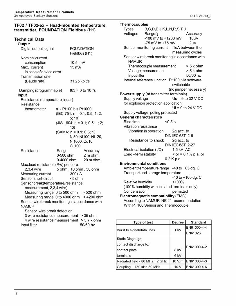
TF02 / TF02-ex – Head-mounted temperaturetransmitter, FOUNDATION Fieldbus (H1)
Technical DataOutput
Digital output signal FOUNDATIONFieldbus (H1)
Nominal currentconsumption 10.5 mA
Max. current 15 mAin case of device error
Transmission rate(Baude rate) 31.25 kbit/s
Damping (programmable) t63 = 0 to 1038sInput
Resistance (temperature linear)Resistance
thermometer n - Pt100 bis Pt1000(IEC 751: n = 0.1; 0.5; 1; 2;
5; 10)(JIS 1604: n = 0.1; 0.5; 1; 2;
10)(SAMA: n = 0.1; 0.5; 1)
Ni50, Ni100, Ni120,Ni1000, Cu10,Cu100
Resistance Range Accuracy0-500 ohm 2 m ohm0-4000 ohm 20 m ohm
Max.lead resistance (Rw) per core2,3,4 wire 5 ohm , 10 ohm , 50 ohm
Measuring current 300 uASensor short-circuit <5 ohmSensor break(temperature/resistance
measurement, 2,3,4 wire)Measuring range 0 to 500 ohm > 520 ohmMeasuring range 0 to 4000 ohm > 4200 ohm
Sensor wire break monitoring in accordance withNAMUR
Sensor wire break detection3 wire resistance measurement > 35 ohm4 wire resistance measurement > 3.7 k ohm
Input filter 50/60 hz
ThermocouplesTypes B,C,D,E,J,K,L,N,R,S,T,UVoltages Range Accuracy
-100 mV to +1200 mV 10µV-75 mV to +75 mV 2µV
Sensor monitoring current 1uA between themeasuring cycles
Sensor wire break monitoring in accordance withNAMURThermocouple measurement > 5 k ohmVoltage measurement > 5 k ohmInput filter 50/60 hz
Internal reference junction Pt 100, via softwareswitchable
(no jumper necessary)Power supply (at transmitter terminals)
Supply voltage Us = 9 to 32 V DCfor explosion protection application
Ui = 9 to 24 V DCSupply voltage, poling protected
General characteristicsRise time <0.5 sVibration resistance
Vibration in operation 2g acc. toDIN IEC 68T .2-6
Resistance to shock 2g acc. toDIN IEC 68T .2-27
Electrical isolation (I/O) 1.5 kV ACLong –term stabilty < or = 0.1% p.a. or
0.2 K p.a.Environmental conditions
Ambient temperature range -40 to +85 dg. CTransport and storage temperature
-40 to +100 dg. CRelative humidity <100%(100% humidity with isolated terminals only)Condensation permitted
Electromagnetic compatibility (EMC)According to NAMUR NE 21 recommendationWith PT100 Sensor and Thermocouple
Ù
Type of test Degree StandardEN61000-4-4EN61326
Static Disgaugecontact discharge to:contact plate 8 kVterminals 6 kVRadiated field - 80 MHz…2 GHz 10 V/m EN61000-4-3Coupling – 150 kHz-80 MHz 10 V EN61000-4-6
Burst to signal/data lines 1 kV
EN61000-4-2

19
Temperature Measurement Products3A Approved Sanitary Sensors D-TS-V1019_2
Mechanical constructionDimensions refer to dimensional drawingWeight 2 ouncesHousing material polycarbonateColor black / blue (Ex version)Terminals, pluggablescrew terminals 2.5 mm2
(stainless steel screws)Influences
Influence of ambient temperaturePt100 + or = 0.25 K/ 10 KResistance measurement
0 to 500 ohm + or = 10 m ohm / 10 K0 to 4000 ohm + or = 100 m ohm / 10 K
Thermocouple e.g.Type K + or = 0.25 K / 10 KVoltage measurement
-100 mV to +1200 mV + or = 150 uV / 10 K-75 mV to +75 mV + or = 10 uV / 10 K
Characteristics at rated conditionsacc. to IEC 770 (related to 25 dg. C)
For more detail information of this temperature transmitter, refer to Data sheet D-TH-F02/TF02EX
Measuring error incl. characteristic deviationPt 100 + or = 0.1 K
Resistance measurement0 to 500 ohm + or = 40 m ohm0 to 4000 ohm + or = 320 m ohm
Thermocouple e.g. Type K + or = 0.25 KVoltage measurement
-100 mV to +1200 mV + or = 50 uV-75 mV to +75 mV + or = 10 uVAdditional influence of the Pt100
DIN IEC 751 KI. B internal reference junctionParameterization / structure
Type of input(2 independent channels),measuring range, Input filter, damping, alarmfunction, limit values, saving
All data proof against mains failure.Standard parameter (factory settings)
Channel 1 Pt 100, 4 wire circuit, 0 to 100 dg. C Damping 0 s, unit dg. C
Channel 2disabled
Table 8
Standard SensorThermocouple Type B 0 to +1820ºC ( +32 to +3308ºF)Thermocouple Type E -270 to +1000ºC (-454 to +1832ºF)Thermocouple Type J -210 to +1200ºC (-346 to +2192ºF)Thermocouple Type K -270 to +1372ºC (-454 to +2502ºF)Thermocouple Type R -50 to +1768ºC ( -58 to +3215ºF)Thermocouple Type S -50 to +1768ºC ( -58 to +3215ºF)Thermocouple Type T -270 to +400ºC (-454 to +752ºF)Thermocouple Type N -270 to +1300ºC (-454 to +2372ºF)
W3, Thermocouple Type C 0 to +2315ºC ( +32 to +4200ºF)ASTME 998 Thermocouple Type D 0 to +2315ºC ( +32 to +4200ºF)
Thermocouple Type L -200 to +900ºC (-328 to +1652ºF)Thermocouple Type U -200 to +600ºC (-328 to +1112ºF)
IEC 751; JIS; SAMA1 Resistance thermometer Pt100 -200 to +850ºC (-328 to +1562ºF)2,3 and 4-wire Resistance thermometer Pt1000 -200 to +850ºC (-328 to +1562ºF)DIN 437602 Resistance thermometer Pt100 -60 to +250ºC ( -76 to +482ºF)2,3 and 4-wire Resistance thermometer Pt1000 -60 to +250ºC ( -76 to +482ºF)(a = 0.00618)Resistance2,3 and 4-wire
-100mV to +1200mV-75mV to +75mV
Notes: 1 IEC 751 a = 0.00385; JIS a = 0.003916; SAMA a = 0.0039022 Edison Curve No. 7 for Ni120
Ω 0 to 500Ω / 0 to 4000Ω
Voltage MV
Input ElementMeasuring Range
IEC 584-1
DIN 43710

20
Temperature Measurement Products3A Approved Sanitary Sensors D-TS-V1019_2
Block Diagram
TF02/TF02-ExHead Mounted Temperature Transmitters, FOUNDATION Fieldbus (H1)Connection Diagram
Dimensional Diagram (dimensions in min)
Value_1 (T1)
Value_2 (T2)
Transducer BlockTB
Sensor 1; (T1)
Sensor 2; (T2)
AI Block 1AI 1
AI Block 2AI 2
Reference junctionPt100
Resource Block
out value sensor 1+ Status
by requestonly read
out value sensor 2+ Status
by requestread/write
1
3
4
2
1
3
4
2
1
3
4
2
1
3
4
2
1
3
4
2
1
3
4
2
1
3
4
2
1
3
4
2
ϑ ϑ ϑ
ϑ
ϑϑ
a) b) c) d) e) f) g) h) i) j)
FoundationFieldbus (H1)
+
-
1
3
4
2
1
3
1
3
Input
Referencejunction
Micro-processorOutput
Ch1Ch1
Ch2
Ch1
Ch2
Ch1
Ch2
Ch1
Ch2
1
34
2 ∅44
,4
23,8Automation - Products
TF 02
Messumformer/Transmitter/Transducteur
5,5
Snap-on fixing for DIN rail mounting(35mm)(optionally)
a) Resistance thermometer, 2 wire circuitb) Resistance thermometer, 3 wire circuitc) Resistance thermometer, 4 wire circuitd) Double resistance thermometer, 2 wire circuite) Potentiometer input, 4 wire circuit
- Resistance measurement analogous zu toResistance thermometer circuits a) to d)
f ) Thermocoupleg) Double thermocoupleh) Combination thermocuple resistance thermometer
(Combination Ch1/pin 1-3: RTD and Ch2/pin 2-4:TC also possible)
i) Voltage measurementj) Double voltage measurementt
- Voltage measurement and ResistanceMeasurement analogous to circuit h) also possible
Figure 22
Figure 23
Figure 24

21
Temperature Measurement Products3A Approved Sanitary Sensors D-TS-V1019_2
TF12 / TF12-ex – Head-mounted temperaturetransmitter, Profibus PA
Technical DataOutput
Digital output signal PROFIBUS PAprofile V3.0Type A and B
Nominal currentconsumption 11.8 mA
Max. current 15 mAin case of device error
Transmission rate 31.25 kbit/sDamping t63 = 0 to 60
InputResistance(temperature linear)Resistance thermometer Pt50 – Pt100 –
Pt1000Resistance 0 to 400 ohm /
0 to 4000 ohmlead resistance (Rw) per core < 5 ohmMeasuring current 200 uASensor short-circuit <5 ohm (for RTD)Sensor break > 5 M ohm
ThermocouplesTypes B,C,D,E,J,K,L,N,
R,S,T,UVoltagesSensor monitoring current 200 UaInput resistance 5 M ohmInput filter 50/60 hzInternal reference junction Pt 100,
programmable
Power supplySupply voltage,
poling protected Us = 9 to 32 V DCfor explosion protection
application Ui = 9 to 17.5 V DC
General characteristicsRise time <0.1 to 1.25 sVibration resistance
Vibration in operation 2 g acc. toDIN IEC 68 part 2-6
Electrical isolation 1.5 kVEnvironment conditions
Ambient temperature range -40 to 85 dg. CTransport and storage
temperature -40 to 100 dg. CRelative humidity < 100%(100% humidity with isolation terminals only)Condensation permissable
Characteristics at rated conditions1)
(acc.to IEC770, related to 25 dg. C)Measuring error includes characteristic deviation
Pt 100 / resistance measurement typ. <0.2%
min. < 0.2 KThermocouple / mV min. < 20 uV
Additional influence of Pt100 DIN IEC 751 cl. Bthe internal reference junction
Mechanical constructionHousing material polycarbonateColor black / blue
(Ex version)Weight 8.8 ouncesTerminals Screw terminals
2.5 mm2
1) Percentage related to set measuring span
For more detail information of this temperature transmitter, refer to Data sheet D-TH-TF12/TF12-ex
Table 9Basis
Standard Sensor Measuring errorThermocouple Type B 400 to +1820ºC ( 752 to +3308ºF) 0.8 KThermocouple Type E -100 to +1000ºC (-148 to +1832ºF) 0.2 KThermocouple Type J -100 to +1200ºC (-148 to +2192ºF) 0.2 KThermocouple Type K -189 to +1370ºC (-292 to +3200ºF) 0.2 KThermocouple Type R -50 to +1760ºC ( -58 to +3200ºF) 0.8 KThermocouple Type S -50 to +1760ºC ( -58 to +3200ºF) 0.8 KThermocouple Type T -200 to +400ºC (-328 to +752ºF) 0.2 KThermocouple Type N -180 to +1300ºC (-292 to +2372ºF) 0.2 KThermocouple Type C 0 to +2300ºC ( 32 to +4172ºF) 0.2 KThermocouple Type D 0 to +2300ºC ( 32 to +4172ºF) 0.2 KThermocouple Type L -100 to +900ºC (-148 to +1652ºF) 0.8 KThermocouple Type U -200 to +600ºC (-328 to +1112ºF) 0.8 K
Resistance thermometer Pt100 -200 to +850ºC (-328 to +1562ºF) 0.4 KResistance thermometer Pt1000 -200 to +850ºC (-328 to +1562ºF) 0.4 K
Resistance thermometer Pt100/Pt1000 -100 to +250ºC (-148 to +482ºF) 0.2 KDIN 43760
(a = 0.00618)Resistance 2, 3, 4-wire 0.10%
Voltage 20 µVNote: 1) a = 0.00385
( -76 to +482ºF) 0.2 K
0 to 400 Ω 0 to 4000 Ω-15 mV to 115 mV
DIN 43710
IEC 751 1)
Resistance thermometer Ni 100 -60 to +250ºC
Input element Measuring range
IEC 584-1
W3, ASTME 998

22
Temperature Measurement Products3A Approved Sanitary Sensors D-TS-V1019_2
Block Diagram
Connection Diagrams
Dimensional Diagram (dimensions in mm.)
a) Resistance thermometer, 2-wire circuitb) Resistance thermometer, 3-wire circuitc) Resistance thermometer, 4-wire circuitd) Double resistance thermometer, 2-wire circuite) Double resistance thermometer, 3-wire circuitf) Thermocoupleg) Double resistance thermometer
h) Combination resistance thermometer thermocouplei) Combination thermocouple resistance thermometer- Resistance measurement analogos to resistance thermometer circuits a) to f)- Voltage measurement analogous to thermcouples circuits f) to i)
PV=SV1: Secondary Value 1PV=SV2: 2PV=SV1 - SV2: DifferencePV=SV2 - SV1: DifferencePV=1/2 x (SV1+SV2): AveragePV=1/2 x (SV1+SV2): Average
/ Redundance
Secondary ValuePrimary_Value / PV
Secondary_Value_1 / SV 1
Secondary_Value_2 / SV2
Transducer BlockTB
Sensor 1; (T1)
Sensor 2; (T2)
Function Block 2FB2
Function Block 1FB1
Function Block 3FB3
Offset
Offset
Temperature 1+ Status
Temperature 2+ Status
Calculated Temperature+ Status
PROFIBUSPA V3.0
+
-
3
4
6
-
+ + +
+ +
ϑ
ϑ
ϑ
ϑϑ
K1
K2a) b) c) d) e) f) g) h) i)
1
3
1
3
2
1
3
4
2ϑ
ϑ
K1
K2
1
3
4
6
5
2ϑ
ϑ
K1
K2
1
3
4
6
3
2
3
6
5
2
3
4
6
5
2
1
3
6
5
2
Z-2
01
58
2
1
5
-
OutputMicroprocessor
Referencejunction
Input
∅ 60
35
Z-20
159
23 4
5
61
Figure 25
Figure 26
Figure 27

23
Temperature Measurement Products3A Approved Sanitary Sensors D-TS-V1019_2
Standard Products=Code
3A Sanitary Sensor Assembly with Thermowell V10196
1 : ReservedReserved -
2 : Thermowell MaterialAISI 304 / 304L SST (1.4301 / 1.4306) HAISI 316 / 316L SST (1.4401 / 1.4404) LOther X
3 : Process Connection SizeTri-Clamp, 1 in. C1Tri-Clamp, 1.5 in. C2Tri-Clamp, 2 in. C3Tri-Clamp, 2.5 in. C4Tri-Clamp, 3 in. C5Tri-Clamp, Other CXCherry Burrell, 1 in. B1Cherry Burrell, 1.5 in. B2Cherry Burrell, 2 in. B3Cherry Burrell, 2.5 in. B4Cherry Burrell, 3 in. B5Cherry Burrell, Other BXProjectile Well PWOther XX
4 : Tip DesignTapered Shank TStep Shank, Standard RStraight Shank S
5 : Thermowell DimensionsU Length 2.5 in. (64 mm), Sensor Length 4 in. (102 mm) (Note: 19) 025U Length 3.0 in. (76 mm), Sensor Length 4.5 in. (114 mm) (Note: 19) 030U Length 3.5 in. (89 mm), Sensor Length 5 in. (127 mm) (Note: 19) 035U Length 4.0 in. (102 mm), Sensor Length 5.5 in. (140 mm) (Note: 19) 040U Length 4.5 in. (114 mm), Sensor Length 6 in. (152 mm) (Note: 19) 045U Length 5.0 in. (127 mm), Sensor Length 6.5 in. (165 mm) (Note: 19) 050U Length 5.5 in. (140 mm), Sensor Length 7 in. (178 mm) (Note: 19) 055U Length 6 in. (152 mm), Sensor Length 7.5 in. (191 mm) (Note: 19) 060U Length 6.5 in. (165 mm), Sensor Length 8 in. (203 mm) (Note: 19) 065U Length 7.0 (178 mm), Sensor Length 8.5 in. (216 mm) (Note: 19) 070U Length 7.5 in. (191 mm), Sensor Length 9 in. (229 mm) (Note: 19) 075U Length 8.0 in. (203 mm), Sensor Length 9.5 in. (241 mm) (Note: 19) 080U Length 8.5 in. (216 mm), Sensor Length 10 in. (254 mm) (Note: 19) 085U Length 9.0 in. (229 mm), Sensor Length 10.5 in. (267 mm) (Note: 19) 090U Length 9.5 in. (241 mm), Sensor Length 11 in. (279 mm) (Note: 19) 095Thermowell Length 10-1/8 in. (257 mm), Taper 3-1/4 in. (83 mm) (Notes: 1, 19) 101Thermowell Length 11-7/8 in. (302 mm), Taper 5 in. (127 mm) (Note: 1,19) 117Thermowell Length 13-1/8 in. (333 mm), Taper 3-3/4 in. (95 mm) (Note:1, 19) 131

24
Temperature Measurement Products3A Approved Sanitary Sensors D-TS-V1019_2
V10196 Code6 : Thermowell Lag Length TNo Lag 03 in. (76 mm) 36 in. (152 mm) 6Other X
7 : Extension Tube / Length E / MaterialUnion-Nipple 3 in. AISI 316S SST (1.4401) SUnion-Nipple 6 in. AISI 316U SST (1.4401) UWithout N
8 : Sensor Type / Sheath Material1 x Pt100, 2-wire / AISI 316Ti SST (1.4571) 21 x Pt100, 3-wire / AISI 316Ti SST (1.4571) 31 x Pt100, 4-wire / AISI 316Ti SST (1.4571) 42 x Pt100, 3-wire / AISI 316Ti SST (1.4571) 61 x Type K, Ungrounded / Inconel 600 (2.4816) (Note: 15) H1 x Type J, Ungrounded / AISI 316Ti SST (1.4571) (Note: 15) G1 x Type E, Ungrounded / Inconel 600 (2.4816) (Note: 15) E1 x Type T, Ungrounded / AISI 316Ti SST (1.4571) (Note: 15) T2 x Type K, Ungrounded / Inconel 600 (2.4816) (Note: 15) J2 x Type J, Ungrounded / AISI 316Ti SST (1.4571) (Note: 15) I2 x Type E, Ungrounded / Inconel 600 (2.4816) (Note: 15) F2 x Type T, Ungrounded / AISI 321 SST (1.4541) (Note: 15) UOther (Note: 15) X
9 : Accuracy according to IEC 60751 & IEC 60584Class B RTD only (Note: 2) AClass 2 Thermocouples only (Note: 3) GClass A RTD only, High (Note: 2) EClass 1 Thermocouples only, High (Note: 3) H
10 : Connection Head / Material / Cable Entry / Class of ProtectionWithout 0Sanitary Head, Polypropylene, 1/2 in. NPT, IP 65 (FDA Approved) WSanitary Head, Stainless Steel, 1/2 in. NPT, NEMA 4X (In Preparation) SB (Basic), Aluminum, 1/2 in. NPT, IP54 (Note: 20) 1BUZH, Aluminum, 1/2 in. NPT,IP 68 5AGL, Aluminum, 1/2 in. NPT, IP 66, IP 67, NEMA 4X (Note: 16) BAGLHD Prometer, Connection Head Aluminum, 1/2 in. NPT, IP 66, IP 67, NEMA 4X (Note: 17) DAGLHD Cometer, Aluminum, 1/2 in. NPT, IP 66, IP 67, NEMA 4X (Note: 17) CAGLHD LCD Integral Display, Aluminum, 1/2 In. NPT, IP 66, IP 67, NEMA 4X (TTH300, TTH300 EX, EXN Only) L
AGLHD LCD Digital Display, Aluminum, 1/2 In. NPT, IP 66, IP 67, NEMA 4X(TF02, TF02EX Only) F
Other X
11 : Head Mounted TransmitterWithout 0TH02 HART Protocol, General Purpose (Notes: 4, 18) 9TF12 PROFIBUS PA (only with BUZH or AGL Connetion Head) (Notes: 5, 18) KTH02-Ex HART Protocol, Intrinsically Safe (Notes: 4, 18) JTH02-ExN HART Protocol, Nonincendive (Notes: 4, 18) PTS04 Programmable via Pushbutton, General Purpose (for 2 / 3 wire RTD only) (Notes: 6, 7, 18) 2TS05-1 Programmable via Pushbutton, General Purpose, Type K, 0 ... 1000 °C (32 ... 1832 °F) (Notes: 8, 7, 18) 5
TS05-3 Programmable via Pushbutton, General Purpose, Type J (Notes: 9, 7, 18) 4TF02 FOUNDATION Fieldbus, LAS Function Standard, General Purpose (Notes: 10, 18) M

25
Temperature Measurement Products3A Approved Sanitary Sensors D-TS-V1019_2
V10196 CodeHead Mounted Transmitter (Cont)TF02-Ex FOUNDATION Fieldbus, LAS Function Standard, Intrinsically Safe (Notes: 10, 18) NTTH300 HART Protocol General Purpose (Note: 11, 18) 6TTH300-Ex, ExN HART Protocol, FM Intrinsically Safe (Class I, Dvi 1) and Nonincendive) Class I, Div 2) (Note: 11,18) 7
Other (Note: 18) XADDITIONAL ORDERING CODE12 : Tip DesignReduced Tip (Fast Response Sensor) RT
13 : Sensor TypeGround Thermocouple 33
14 : Name PlateTag No. on Stainless Steel Label SL
15 : Pressure Test - InternalInternal Pressure Test of the Thermowell IP
16 : Pressure Test - ExternalExternal Presure Test for Flanged Tw of up to U = 36 In. EP
17 : Heat TreatNACE per MR 0175 NA
18 : Dye Penetration TestDye Penetration Test DP
19 : Option: Oxygen ServiceOxygen Clean OC
20 : Thermowell CalculationVelocity Calculation (Tapered Thermowells Only) VC
21 : PMI TestPositive Material Identification of the Thermowell (PMI) PM
22 : Thermowell Option4 … 12 RMS High Polish Stem Finish 4F
23 : Calibration2 PT Certified Calibration (TH02, TH02-Ex, TH02-ExN Only) (Note: 12) 2P5 PT Certified Calibration (TTH300, TTH300-Ex, TTH300-ExN Only) (Note: 13) 5P9 PT Certified Calibration (TH02, TH02-Ex, TH02-ExN Only) (Note: 12) 9PCallendar-van Dusen Sensor Match Calibration (TTH300, TTH300-Ex, TTH300-ExN Only)
(Note: 13) CD
9 PT Sensor Match Calibration (TH02, TH02-Ex, TH02-ExN Only) (Note: 12) MC
24 : SIL2 TUV CertificateTUV Certificate for Functional Safety SIL2 acc. IEC61508 (Note: 14) S2
25 : Other OptionsSpecify XX
26: Registration NumberCRN-Canadian Registration Number CR
26
Temperature Measurement Products3A Approved Sanitary Sensors D-TS-V1019_2
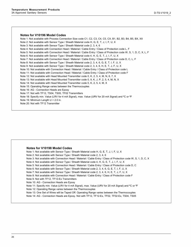
Notes for V10198 Model CodesNote 1: Not available with Sensor Type / Sheath Material code H, G, E, T, J, I, F, U, XNote 2: Not available with Sensor Type / Sheath Material code 2, 3, 4, 6Note 3: Not available with Connection Head / Material / Cable Entry / Class of Protection code W, S, 1, D, C, XNote 4: Not available with Sensor Type / Sheath Material code 4, H, G, E, T, J, I, F, U, XNote 5: Not available with Connection Head / Material / Cable Entry / Class of Protection code D, CNote 6: Not available with Sensor Type / Sheath Material code 2, 3, 4, 6, G, E, T, I, F, U, XNote 7: Not available with Sensor Type / Sheath Material code 2, 3, 4, 6, H, E, T, J, F, U, XNote 8: Not available with Connection Head / Material / Cable Entry / Class of Protection code FNote 9: Not with TF12, TF12-Ex TransmittersNote 10: AG - Connection Heads are EpoxyNote 11: Specify min. Value (LRV for 4 mA Signal), max. Value (URV for 20 mA Signal) and ºC or ºFNote 12: Operating Range varies between the ThermocouplesNote 13: One Set of Wires will be Taped Off. Operating Range varies between the ThermocouplesNote 14: AG - Connection Heads are Epoxy. Not with TF12, TF12-Ex, TF02, TF02-Ex, TS04, TS05
Notes for V10196 Model CodesNote 1: Not available with Process Connection Size code C1, C2, C3, C4, C5, CX, B1, B2, B3, B4, B5, BX, XXNote 2: Not available with Sensor Type / Sheath Material code H, G, E, T, J, I, F, U, XNote 3: Not available with Sensor Type / Sheath Material code 2, 3, 4, 6Note 4: Not available with Connection Head / Material / Cable Entry / Class of Protection code L, FNote 5: Not available with Connection Head / Material / Cable Entry / Class of Protection code W, S, 1, D, C, X, L, FNote 6: Not available with Sensor Type / Sheath Material code 4, H, G, E, T, J, I, F, U, XNote 7: Not available with Connection Head / Material / Cable Entry / Class of Protection code D, C, L, FNote 8: Not available with Sensor Type / Sheath Material code 2, 3, 4, 6, G, E, T, I, F, U, XNote 9: Not available with Sensor Type / Sheath Material code 2, 3, 4, 6, H, E, T, J, F, U, XNote 10: Not available with Connection Head / Material / Cable Entry / Class of Protection code LNote 11: Not available with Connection Head / Material / Cable Entry / Class of Protection code FNote 12: Not available with Head Mounted Transmitter code 0, K, 2, 5, 4, M, N, 6, 7, XNote 13: Not available with Head Mounted Transmitter code 0, 9, K, J, P, 2, 5, 4, M, N, XNote 14: Not available with Head Mounted Transmitter code 0, K, 2, 5, 4, M, XNote 15: Operating Range varies between the ThermocouplesNote 16: AG - Connection Heads are EpoxyNote 17: Not with TF12, TS04, TS05, TF02 TransmittersNote 18: Specify min. Value (LRV for 4 mA Signal), max. Value (URV for 20 mA Signal) and ºC or ºFNote 19: Minimum Length U = 2.0 in.Note 20: Not with TF12 Transmitter

27
Temperature Measurement Products3A Approved Sanitary Sensors D-TS-V1019_2
Standard Products=Code
3A Sanitary Sensor Assembly without Thermowell V10198
1 : Dash Characteristic 07Reserved -
2 : Process Connection OptionsAlloy Products, Clamp Fittings ACherry-Burrell, Clamp Fittings CTri-Clamp, Clamp Fittings TAlloy Products, Bevel Seat Fittings, 13H Nut PCherry-Burrell, Bevel Seat Fittings, 13H Nut BTri-Clamp, Bevel Seat Fittings, 13H Nut ROther X
3 : Length X - See Sensor Design - Part 1 (10 in.) Increment0 010 in. (254 mm) 120 in. (508 mm) 230 in. (762 mm) 3Other X
4 : Length X - See Sensor Design - Part 2 (1 in.) Increment0 01 in. (25 mm ) 12 in. (51 mm ) 23 in. (76 mm ) 34 in. (102 mm) 45 in. (177 mm) 56 in. (152 mm) 67 in. (178 mm) 78 in. (203 mm) 89 in. (229 mm) 9
5 : Length X - See Sensor Design - Part 3 (0.25 in.) Increment0 00.25 in. (6 mm ) 20.5 in. (13 mm ) 50.75 in (19 mm ) 7
6 : Process Connection Size1.5 in. (38 mm ) 12 in. (51 mm ) 22.5 in. (64 mm ) 53 in. (76 mm ) 34 in. (102 mm) 4Without N
7 : PolishNumber 4 Finish, High Polish HElectropolish EPassivate P

28
Temperature Measurement Products3A Approved Sanitary Sensors D-TS-V1019_2
V10198 Code
8 : Sensor Type / Sheath Material1 x Pt100, 2-wire / AISI 316Ti SST (1.4571) (Note: 12) 21 x Pt100, 3-wire / AISI 316Ti SST (1.4571) (Note: 12) 31 x Pt100, 4-wire / AISI 316Ti SST (1.4571) (Note: 12) 42 x Pt100, 3-wire / AISI 316Ti SST (1.4571) (Note: 13) 61 x Type K / Inconel 600 (2.4816) (Note: 12) H1 x Type J / AISI 316Ti SST (1.4571) (Note: 12) G1 x Type E / Inconel 600 (2.4816) (Note: 12) E1 x Type T / AISI 316Ti SST (1.4571) (Note: 12) T2 x Type K / Inconel 600 (2.4816) (Note: 13) J2 x Type J / AISI 316Ti SST (1.4571) (Note: 13) I2 x Type E / Inconel 600 (2.4816) (Note: 13) F2 x Type T / AISI 321 SST (1.4541) (Note: 13) UOther X
9 : Accuracy according to IEC 60751 & IEC 60585Class B RTD only (Note: 1) AClass 2 Thermocouples only (Note: 2) GClass A RTD only (Note: 1) EClass 1 Thermocouples only (Note: 2) H
10 : Connection Head / Material / Cable Entry / Class of ProtectionWithout, Aluminum 1/2 in. NPT 0Sanitary Head, Polypropylene, 1/2 in. NPT, IP 65 (FDA Approved) WSanitary Head, Stainless Steel, 1/2 in. NPT, NEMA 4X (In Preparation) SB (Basic), Aluminum, 1/2 in. NPT, IP 54 (Note: 9) 1BUZH, Aluminum, 1/2 in. NPT,IP 68 5AGL, Aluminum, 1/2 in. NPT, IP 66, IP 67, NEMA 4X (Note: 10) BAGLHD Prometer, Connection Head Aluminum, 1/2 in. NPT, IP 66, IP 67, NEMA 4X (Note: 14) DAGLHD Cometer, Aluminum, 1/2 in. NPT, IP 66, IP 67, NEMA 4X (Note: 14) CAGLHD LCD Integral Display, Aluminum, 1/2 In. NPT, IP 66, IP 67, NEMA 4X (TF02, TF02EX O l )
FAGLHD LCD Digital Display, Aluminum, 1/2 In. NPT, IP 66, IP 67, NEMA 4X (TTH300, TTh300 Ex, EXN Only L
Other X
11 : Head Mounted TransmitterWithout 0TH02 HART Protocol, General Purpose (Note: 8, 11) 9TF12 PROFIBUS PA (only with BUZH or AGL Connection Head) (Notes: 3, 5, 11) KTH02-Ex HART protocol, Intrinsically Safe (Note: 8, 11) JTH02-ExN HART Protocol, Non-incendive (Note: 11) PTS04 Programmable via Pushbutton, General Purpose (for 2 / 3 wire RTD only) (Notes: 4, 5, 11) 2TS05-1 Programmable via Pushbutton, General Purpose, Type K, 0 ... 1000 °C (32 ... 1832 °F)
(Notes: 5,6, 11) 5
TS05-3 Programmable via Pushbutton, General Purpose Type J (Notes: 5, 7, 11) 4TF02 FOUNDATION Fieldbus, LAS Function Standard, General Purpose (Note: 11) MTF02-Ex FOUNDATION Fieldbus, LAS Function Standard, FM Intrinsically Safe (Note: 11) NTTH300 HART Protocol General Purpose (Note: 8) 6TTH300-Ex, ExN HART Protocol, FM Intrinsically Safe (Class I, Dvi 1) and Nonincendive) Class I, Div 2) (Note: 8) 7
Other X

29
Temperature Measurement Products3A Approved Sanitary Sensors D-TS-V1019_2
Order number example:V10196-LC3R0450S3AW9 Thermowell
L = 316 Stainless Steel (Standard)C3 = 2” Tri-Clamp connectionR = Step shank design045 = Insertion = 4 1/2” (U Dimension)0 = no LagS = 3” Union-nipple extension3 = 3 wire RSDA = Standard AccuracyW = Polyproplene head9 = TH02 Transmitter
V10188-2 - Calculation of the “X” Dimension
Figure 28

30
Temperature Measurement Products3A Approved Sanitary Sensors D-TS-V1019_2
The Company’s policy is one of continuous productimprovement and the right is reserved to modifythe information contained herein without notice.
Printed in USA (2.22.08)
© ABB 2006, 2008
D-T
S-V1
019_
2
ABB has Sales & Customer Supportexpertise in over 100 countries worldwide
www.abb.com/instrumentation
ABB Inc.125 East County Line RoadWarminsterPA 18974USATel: +1 215 674 6000Fax: +1 215 674 7183
ABB LtdSalterbeck Trading EstateWorkington, CumbriaCA14 5DSUKTel: +44 (0)1480 475321Fax: +44 (0)1480 217948
Notes