d11 engl druckfrei - i s systems · 660 kva to 9100 kva order no.: ... plies) are identified by...
TRANSCRIPT

Related catalogs
SINAMICS G110 D 11.1Inverter chassis units0.12 kW to 3 kWOrder No.:German: E86060-K5511-A111-A1English: E86060-K5511-A111-A1-7600
SINAMICS S120 D 21.2Servo control drive system
Order No.:German: E86060-K5521-A121-A1English: E86060-K5521-A121-A1-7600
SINAMICS S150 D 21.3Drive converter cabinet units75 kW to 1200 kWOrder No.:German: E86060-K5521-A131-A1English: E86060-K5521-A131-A1-7600
SIMOVERT MV DA 63Medium-voltage drives660 kVA to 9100 kVAOrder No.:German: E86060-K5363-A101-A2English: E86060-K5363-A101-A2-7600
SIMOVERT DA 65.10MASTERDRIVES VC0.55 kW to 2300 kWOrder No.:German: E86060-K5165-A101-A3English: E86060-K5165-A101-A3-7600
Low-voltage motors M 11
Order No.:German: E86060-K1711-A101-A3English: E86060-K1711-A101-A3-7600
Components for CA 01Automation
Order No.:German: E86060-D4001-A100-C1English: E86060-D4001-A100-C1-7600
A&D Mall
Internet:http://www.siemens.com/automation/mall
Trademarks
All designations marked in this catalog with ® are registered trademarks of Siemens AG.Other designations used in this document may be trademarks; the owner's rights may be violated if they are used by third parties for their own purposes.
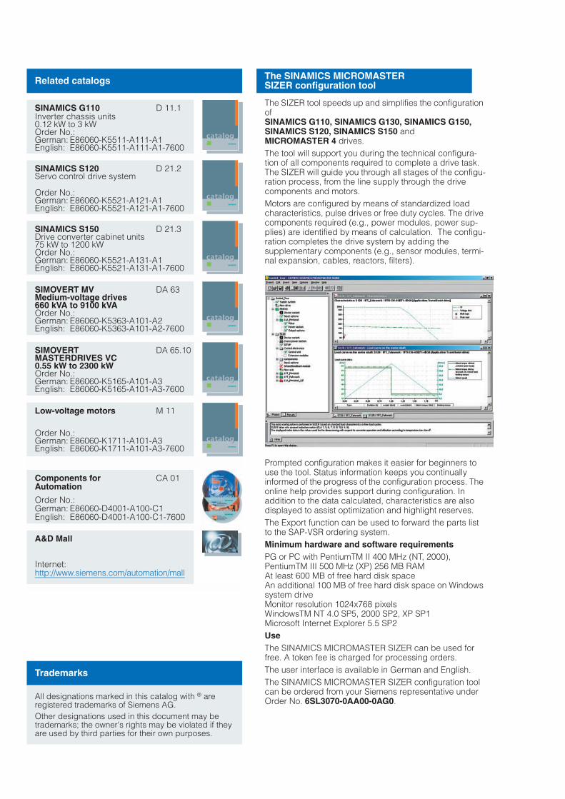
The SINAMICS MICROMASTER SIZER configuration tool
The SIZER tool speeds up and simplifies the configuration ofSINAMICS G110, SINAMICS G130, SINAMICS G150,SINAMICS S120, SINAMICS S150 and MICROMASTER 4 drives.The tool will support you during the technical configura-tion of all components required to complete a drive task. The SIZER will guide you through all stages of the configu-ration process, from the line supply through the drive components and motors.Motors are configured by means of standardized load characteristics, pulse drives or free duty cycles. The drive components required (e.g., power modules, power sup-plies) are identified by means of calculation. The configu-ration completes the drive system by adding the supplementary components (e.g., sensor modules, termi-nal expansion, cables, reactors, filters).
Prompted configuration makes it easier for beginners to use the tool. Status information keeps you continually informed of the progress of the configuration process. The online help provides support during configuration. In addition to the data calculated, characteristics are also displayed to assist optimization and highlight reserves.The Export function can be used to forward the parts list to the SAP-VSR ordering system.Minimum hardware and software requirementsPG or PC with PentiumTM II 400 MHz (NT, 2000),PentiumTM III 500 MHz (XP) 256 MB RAMAt least 600 MB of free hard disk spaceAn additional 100 MB of free hard disk space on Windows system driveMonitor resolution 1024x768 pixelsWindowsTM NT 4.0 SP5, 2000 SP2, XP SP1Microsoft Internet Explorer 5.5 SP2UseThe SINAMICS MICROMASTER SIZER can be used for free. A token fee is charged for processing orders.The user interface is available in German and English.The SINAMICS MICROMASTER SIZER configuration tool can be ordered from your Siemens representative underOrder No. 6SL3070-0AA00-0AG0.

s
Replaces:Catalog D 11 · November 2002
© Siemens AG 2004
SINAMICS G130Drive Converter Chassis UnitsSINAMICS G150Drive Converter Cabinet Units
Catalog D 11 · 2004
Introduction Welcome to A&DTotally IntegratedAutomationSINAMICSsystem overviewOverviewSINAMICS G110SINAMICS G130SINAMICS G150
1
SINAMICS G130 Drive converter chassis units
OverviewBenefitsApplicationDesignFunctionTechnical DataSelection and ordering dataComponentsSignal cables
2
SINAMICS G150 Drive converter cabinet units
OverviewBenefitsApplicationDesignFunctionTechnical DataSelection and ordering dataAccessoriesOptions
3
Engineeringinformation
Selection guidesConfiguring the SINAMICS G130 drive converter chassis unitsConfiguring the SINAMICS G150 drive converter cabinet unitsDimensioning drivesMotors
4
Services and documentation
TrainingTraining casesService & SupportDocumentation
5
Appendix Siemens contacts worldwideA&D online servicesSubject and order number indexTerms and conditions of sale and deliveryExport regulations
6
The products and systems described in this catalog are manu-factured under applica-tion of a certified quality management system in accordance with DIN EN ISO 9001.The certificate is recognized in all IQ Net countries.

!"!
!# $%# &
"!& % #
# !$ $"
'
("$ !("
$ ) & #% !
%% " $
#'
% $"'%"
! % !&# %"
$!# '
("$"'


%("$ !& % ! "!#! % !*#!$ !& "!# "! ' " "# +# + " &("$ !*, !!,#% ! '("$ !$ #% !% # +% ! $ # $
-
- # . )$
!% $-/ "!
"
#
#
!$% $
$ &#$
$#'! () !
* *! +
!*
#',!
!
$ !%, !
!$!-
!$ .
$*/

# ##$'("!+ $ $ !&$ &# !! $$ #&" #% "#%% " '% &" " !#" %% "!$ #% !% # # "'
!
!$'-0
! !
+/ !
' * &
!$ $!1 $ !
!$$ & !
!$22
!&!%$!
#',!
!%#%$0
2! 3*!
!$/ &#
!##% $ !
!%,4%$
!#$#* $ !%$!!#.

Introduction
The SINAMICS drive family
1/6 Siemens D 11 · 2004
1
SINAMICS applications
Applications
SINAMICS is the new family of Siemens converters designed for machine and plant engineering applications. SINAMICS offers solutions for all drive tasks:7 Simple pump and fan applications in the process industry.7 Complex individual drives in centrifuges, presses, extruders,
elevators, as well as conveyor and transport systems.7 Drive line-ups in textile, plastic film, and paper machines, as
well as in rolling mill plants.7 Highly dynamic servo drives for machine tools, as well as
packaging and printing machines.
Versions
Depending on the application, the SINAMICS range offers the ideal version for any drive task.7 SINAMICS G is designed for standard applications with asyn-
chronous motors. These applications have less stringent re-quirements regarding the dynamics and accuracy of the mo-tor speed.
7 SINAMICS S handles complex drive tasks with synchro-nous/asynchronous motors and fulfills stringent requirements regarding:
- Dynamics and accuracy- Integration of extensive technological functions in the drive
control system
Platform Concept and Totally Integrated Automation
All SINAMICS versions are based on a platform concept. Joint hardware and software components, as well as standardized tools for design, configuration, and commissioning tasks ensure high-level integration across all components. SINAMICS han-dles a wide variety of drive tasks with no system gaps. The dif-ferent SINAMICS versions can be easily combined with each other.
SINAMICS is a part of the Siemens "Totally Integrated Auto-mation" concept. Integrated SINAMICS systems covering configuration, data storage and communication at automation level, ensure low-maintenance solutions with SIMATIC® and SIMOTION®.
&' 0
' &!
5
5
0
110
-0
$ !

Introduction
The SINAMICS drive family
1/7Siemens D 11 · 2004
1
SINAMICS as part of the Siemens modular automation system
Quality to DIN EN ISO 9001
SINAMICS conforms with the most exacting quality require-ments. Comprehensive quality assurance measures at the pro-duct design stage, as well as in all development and production processes, ensure a consistently high level of quality.
Of course, our quality assurance system is certified by an inde-pendent authority to DIN EN ISO 9001.

Introduction
The SINAMICS drive family
1/8 Siemens D 11 · 2004
1The SINAMICS family comprises members tailored to the re-spective application fields:7 SINAMICS G110 – the versatile drive in the lower power range7 SINAMICS G130 and SINAMICS G150 – the universal drive
solution for single drives with high output ratings7 SINAMICS S120 – the flexible, modular drive system for
demanding drive tasks7 SINAMICS S150 – the sophisticated drive solution for single
drives with high output ratings.
SINAMICS ...
SINAMICS is characterized by the following system features:• Uniform functionality based on a common platform strategy• Uniform engineering• High degree of flexibility and combination• Wide output power range• Designed for worldwide use• SINAMICS Safety Integrated• Increased economy and effectiveness• Flexible interfacing facilities to host controllers• Totally Integrated Automation.
'1
2 % " % "
# % !
3$+# % ! $ 4
667
667
667
!687 697 6)7&!6)7
6)7 !687697 !6)7!687
6)7 !687697 !6)70
0
-0
5

Introduction
The members of the SINAMICS family
1/9Siemens D 11 · 2004
1SINAMICS G110 SINAMICS G130/G150 SINAMICS S120 SINAMICS S150
The versatile drive in the lower power range
The universal drive solution for single drives with high output ratings
The flexible, modular drive system for demanding drive tasks
The sophisticated drive solution for single drives with high output ratings
Main applications
•Machines and plants for industrial and commercial applications
•Machines and plants for process and production applications, water/waste, power plants, oil and gas, petrochemicals, basic chemical industry, paper, cement, stone, steel
•Machines and plants for industrial applications (packaging, plastics, tex-tiles, printing, wood, glass,ceramics, presses, paper, hoisting gear, semiconduc-tors, automatic assembly and testing units, handling)
•Machines and plants for pro-cess and production appli-cations, food and beverage industry, automotive and steel industry, deep/open-cast mining, shipbuilding, hoisting gear/conveyor tech-nology
Application examples
•Pumps and fans•Auxiliary drives•Conveyor belts•Billboards•Gate/door openers•Centrifuges
•Pumps and fans•Compressors•Extruders and mixers•Mills
•Motion control applications (e.g. positioning, synchro-nous speed)
•Technological applications
•Test bay drives•Centrifuges•Elevators and cranes•Cross cutters and shears•Conveyor belts•Presses•Cable winches
Highlights
•Compact•Flexible adaptation to
different applications•Simple, fast start-up•Ready-to-use•Clearly arranged terminals•Optimum interaction with
SIMATIC and LOGO!
•Space-saving•Low noise•Simple, fast start-up•SINAMICS G130:
modular components•SINAMICS G150:
cabinet unit ready to connect
•Optimum interaction with SIMATIC
•For universal use•Flexible, modular•Scalable power, function,
number of axes and per-formance
•Simple, fast start-up, auto-configuration
• Innovative system architecture
•Wide range of motors•Optimum interaction with
SIMOTION and SIMATIC•SINAMICS Safety Integrated
•Standard four-quadrant operation
•High control accuracy and dynamic response
•Almost line harmonic reaction-free
•Tolerant towards variations in mains voltage
•Possibility for compensation of reactive power
•Simple, fast start-up•Cabinet unit ready to
connect•Optimum interaction with
SIMATIC

SINAMICS G110 system overview
The versatile drive in the lower power range
1/10 Siemens D 11 · 2004
1 Overview
SINAMICS G110 inverter chassis units are frequency inverters for the whole range of industrial variable-speed drive applica-tions. The particularly compact SINAMICS G110 inverter works with voltage/frequency control (V/f) and is the ideal frequency in-verter solution in the lower output and performance ranges of the SINAMICS product family.
The inverter is available in three housing sizes, and covers a range of outputs from 0.12 kW to 3.0 kW for connection to single-phase supplies of 200 V to 240 V.
For further information see Catalog D 11.1
Benefits
• Flexible use due to comprehensive parameterization facilities and various interfaces (analog and USS versions)
• Simple installation, parameterization and commissioning• Powerful diagnostic facilities with optional operator panel• Fast standard commissioning by copying parameters using
the optional operator panel• Low-noise motor operation resulting from high pulse fre-
quency• Low mechanical wear through
- skipped frequency band in case of resonance- programmable ramp-up/ramp-down times- ramp smoothing and- connection of the converter to the rotating motor
(flying restart)• Increase in plant availability as a result of automatic restarting
following a power failure or stoppage• Fast current limitation for fault-free operation in the event of
sudden load surges• Versions with integral EMC filters for industrial and public sup-
plies• DIP switches for quickly adapting to 50 Hz or 60 Hz applica-
tions• DIP switches for simple bus termination for the USS
version (RS485)
Application
The SINAMICS G110 is particularly suitable• for use as a drive in industrial and commercial applications• in many different sectors, e.g. food, textile, packaging• in conveyor system applications• for applications using pumps and fans• for factory gate, garage door operating mechanisms and
barrier openers• as a drive for changing advertisement panels.
Design
SINAMICS G110 inverters are compact units that are ready to connect. All units contain state-of-the-art IGBT technology in the power section as well as digital microprocessor technology. SINAMICS G110 inverters are quick to install and easy to con-nect.
SINAMICS G110 is available with an analog input or an RS485 communications interface (USS). The digital inputs can be pro-grammed as required, and thus can be adapted flexibly to a wide range of applications. A version with a rib-free heat sink is particularly suitable for installation in flat control cabinets.
The SINAMICS G110 is programmed either from a PC using the STARTER commissioning tool or using an optional basic opera-tor panel. For a standard commissioning of several converters with the same parameters, the entered settings can be saved in the operator panel and can be easily transferred to each further converter.

SINAMICS G110 system overview
The versatile drive in the lower power range
1/11Siemens D 11 · 2004
1 Integration
SINAMICS G110 configuration example(USS version together with SIMATIC S7-200, connection between PC and inverter using optional PC connection kit)
Technical data
!%$!667
(5+1((1
.11
6$
9$
! +#
" !
0
0
-0
6
Electrical data
Supply voltages;output ranges
200 V to 240 V 1 AC, ±10%;0.12 kW to 3.0 kW
Supply systems IT, TN, TT
Line frequency 50/60 Hz
Output frequency 0 Hz to 650 Hz
Control methods V/f control, linear (M~n)V/f control, quadratic (M~n²)V/f control, programmable
Fixed frequencies 3, programmable
Skipped frequency ranges 1, programmable
Digital inputs 3 programmable 24 V DC digital inputs
Analog input (for analog version)
1 analog input for setpoints from 0 V to 10 V, scaleable or for use as 4th digital input
Digital output 1 DC 24 V digital output
Communication interface(for USS version)
RS485 serial interface for use with USS protocol
Functions
Software functions • Automatic restart following inter-ruptions in operation due to a power failure
• Smooth connection of the con-verter to the rotating motor
• Programmable ramp-up/ramp-down times
• Ramp smoothing
Protective functions • Undervoltage• Overvoltage• Earth fault• Short-circuit• Stall prevention• Thermal motor protection I²t• Converter overtemperature• Motor overtemperature
Suitable motors Asynchronous motors
Mechanical data
Degree of protection IP20
Type of cooling
• Converters ≤ 0.75 kW Convection cooling, version with flat heat sink
• Converters > 0.75 kW Internal air cooling(integral fan)
Standards
Compliance with standards CE, UL, cUL, c-tick

SINAMICS G130/G150 system overview
The universal drive solution for single driveswith high output ratings
1/12 Siemens D 11 · 2004
1 Overview
SINAMICS G130 converter chassis units and SINAMICS G150 converter cabinet units are designed for variable-speed drives in machine building and plant construction.
They have been specially tuned to the requirements of drives with quadratic and constant load characteristics, with medium performance requirements and without regenerative feedback.
The control accuracy of the sensorless vector control is suitable for most applications, and additional actual speed value encod-ers are therefore superfluous.
However, the SINAMICS G130/G150 converters are optionally available with an encoder evaluator in order to handle applica-tions that require an encoder for plant-specific reasons.
The SINAMICS G130 and SINAMICS G150 offer an economic drive solution that can be matched to customers' specific re-quirements by adding from the wide range of available compo-nents and options.
Benefits
• Particularly quiet and compact converters due to the use of state-of-the-art IGBT power semiconductors and an innova-tive cooling concept.
• All unit modules are easily accessible, making them extremely service-friendly
• Can be easily integrated into automation solutions due to PROFIBUS interface supplied as standard and various analog and digital interfaces
• Increase in plant availability since individual modules and power components can be replaced quickly and easily
• Easy commissioning and parameterization using interactive menus on the user-friendly AOP30 operator panel with graph-ical LCD and plain-text display.
Application
Variable-speed drives are advantageous for all applications that involve moving, conveying, pumping or compressing solids, liquids or gases.
This means the following applications, in particular:• Pumps and fans• Compressors• Extruders and mixers• Mills
Design
SINAMICS G130
The SINAMICS G130 provides machine builders and plant con-structors with a modular drive system that can be tailored to spe-cific applications.
SINAMICS G130 consists of two modular, stand-alone compo-nents:• Power module and• Control unit
They may be located separately from one another or combined in a single unit. The power module contains a slot for the control unit.
The user-friendly AOP30 operator panel can be used for com-missioning and local operation.
Predefined interfaces, via terminal block or PROFIBUS, make commissioning and control of the drive much easier. The control unit interfaces can be supplemented with add-on modules.
SINAMICS G150
SINAMICS G150 are ready-to-connect AC/AC converters in the standard control cabinet.
They can be matched to individual requirements by selecting from an extensive range of options.
Available with cabinet widths from 400 mm upwards in intervals of 200 mm, with various degrees of protection up to IP54 and two design versions.7 Version A
offers sufficient space for all the options available.The different variants allow the power and motor connections to be arranged at the top or bottom, as required, which in turn offers excellent flexibility in terms of location in the plant.
7 Version Cis a particularly space-saving version envisaged for applica-tions where the power supply components are accommo-dated in a central low-voltage distribution unit and need not be provided again in the control cabinet.
The user-friendly AOP30 operator panel is fitted as standard in the cabinet door for both versions.

SINAMICS G130/G150 system overview
The universal drive solutionfor single drives with high output ratings
1/13Siemens D 11 · 2004
1 Integration
Configuration example for SINAMICS G130 and SINAMICS G150 with SIMATIC S7
!"#
$
%
& '
(
))
!"#
!%$!6)7
!$!1!$2
9$
!%$!697
9$
! +#
!$877$4$
47
" !
0
0
-0
8
" !

SINAMICS G130/G150 system overview
The universal drive solutionfor single drives with high output ratings
1/14 Siemens D 11 · 2004
1 Technical data
SINAMICS G130 SINAMICS G150
Electrical data
Supply voltages; output ranges
• 380 V to 480 V 3 AC, ±10% (-15% < 1 min) 315 kW to 560 kW 110 kW to 560 kW
• 660 V to 690 V 3 AC, ±10% (-15% < 1 min) 315 kW to 800 kW 75 kW to 800 kW
Supply systems IT, TN, TT
Line frequency 47 Hz to 63 Hz
Output frequency 0 Hz to 300 Hz
Control method Vector control with and without sensor or V/f control
Fixed speeds 15 fixed speedsplus 1 basic speed, programmable
Skipped speed ranges 4, programmable
Customer's terminal block Digital inputs/outputs Analog inputs/outputs Inputs for motor temperature evaluation
Communication interface PROFIBUS DP as standard
Braking operation Braking module as system component Braking module optional
Functions
Software functions • Automatic restart following interruptions in operation due to a power failure• Smooth connection of the converter to the rotating motor• Kinetic buffering• Automatic motor identification for control optimization• Programmable ramp-up/ramp-down times• Ramp smoothing
Protective functions • Undervoltage• Overvoltage• Earth fault• Short-circuit• Stall prevention• Thermal motor protection I²t• Thermal converter protection
Suitable motors Asynchronous motors
Mechanical data
Degree of protection IP00for 315 kW/690 V: IP20
IP20optionally IP21, IP23, IP54
Type of cooling Internal fan (forced air ventilation)
Noise level LpA (1 m) at 50 Hz ≤ 73 dB ≤ 72 dB
Cabinet system - Rittal TS 8
Standards
Compliance with standards CE, cULus ( available soon) CE

Siemens D 11 · 2004
2/2 Overview
2/2 Benefits
2/2 Application
2/2 Design
2/4 Function2/4 Communication with higher-level
control and customer's terminal block
2/4 Open-loop and closed-loop control functions
2/4 Software and protection functions
2/5 Technical data2/6 Derating data2/7 Overload capability2/7 EMC information
Selection and ordering data
2/8 Line-side power components
2/8 Line filters2/10 Line reactors2/11 Assignment overview
2/12 Power modules
2/16 DC link components2/16 Braking modules2/18 Braking resistors
2/19 Control unit kit
2/21 Supplementary system components
2/21 TB30 terminal board2/23 TM31 terminal module2/25 SMC30 sensor module
cabinet-mounted2/26 AOP30 advanced operator panel
2/27 Signal cables
SINAMICS G130Drive converter chassis units

SINAMICS G130Drive converter chassis units
315 kW to 800 kW
2/2 Siemens D 11 · 2004
2
Overview
SINAMICS G130 drive converter chassis units
The SINAMICS G130 is an AC/AC converter that can be com-bined very flexibly with the associated system components and integrated into customer-specific control cabinets or directly into machines.
The SINAMICS G130 drive converter chassis units are available for the following voltages and outputs:
A wide range of add-on electrical components allow the drive system to be optimized for specific requirements. Configuration and commissioning are greatly simplified by predefined inter-faces.
The control accuracy of the sensorless vector control is suitable for most applications, and additional actual speed value encod-ers are therefore superfluous.
However, the SINAMICS G130 converters are optionally avail-able with an encoder evaluator in order to handle applications that require an encoder for plant-specific reasons.
Communication between the control unit, the power module and other active SINAMICS components takes place via DRIVE-CLiQ - the drive's internal interface. The DRIVE-CLiQ connec-tions, which are available as preassembled cables of different lengths, allow a complete converter system to be quickly put to-gether.
A PROFIBUS interface is provided as standard to communicate with the control system. The units also have a customer terminal block with digital and analog inputs and outputs.
Benefits
• Particularly quiet and compact converters due to the use of state-of-the-art IGBT power semiconductors and an innova-tive cooling concept.
• All unit modules are easily accessible, making them extremely service-friendly
• Can be easily integrated into automation solutions due to PROFIBUS interface supplied as standard and various analog and digital interfaces
• Increase in plant availability since individual modules and power components can be replaced quickly and easily
• Easy commissioning and parameterization using interactive menus on the user-friendly AOP30 operator panel with graph-ical LCD and plain-text display.
Application
Variable-speed drives are advantageous for all applications that involve moving, conveying, pumping or compressing solids, liquids or gases.
This means the following applications, in particular:• Pumps and fans• Compressors• Extruders and mixers• Mills
Design
The SINAMICS G130 provides machine builders and plant con-structors with a modular drive system that can be tailored to spe-cific applications.
SINAMICS G130 consists of two modular, stand-alone compo-nents:• Power module and• Control unit
They may be located separately from one another or combined in a single unit. The power module contains a slot for the control unit.
The user-friendly AOP30 operator panel can be used for com-missioning and local operation.
Predefined interfaces, via terminal block or PROFIBUS, make commissioning and control of the drive much easier. The control unit interfaces can be supplemented with add-on modules.
Supply voltage Output
380 V to 480 V 315 kW to 560 kW
660 V to 690 V 315 kW to 800 kW

SINAMICS G130Drive converter chassis units
315 kW to 800 kW
2/3Siemens D 11 · 2004
2
Design (continued)
$ 0
1!# 9
$ , 4 -
( !2 ( !
7# )
!
" !
2 $2 $
: :% :
+ *-
! /

SINAMICS G130Drive converter chassis units
315 kW to 800 kW
2/4 Siemens D 11 · 2004
2
Function
Communication with higher-level control and customer's terminal block
A PROFIBUS interface is provided on the CU320 control unit as standard for use as the customer interface. An optional TM31 terminal module is also available.
You can use this customer terminal block to connect the system to the higher-level controller using analog and digital signals, or to connect additional units.
To simplify configuration and commissioning of the drive, the TM31 terminal module is supplied with factory default settings (→ Engineering information).
Open-loop and closed-loop control functions
The converter closed-loop control contains a high-quality sen-sorless vector control with speed and current controls as well as motor and converter protection.
Software and protection functions
The software functions available as standard are described below:
1) Factory setting: not activated (can be programmed)
Software and protection functions Description
Setpoint input The setpoint can be defined internally or externally, internally as a fixed, motorized potentiometer or jog setpoint, externally via the PROFIBUS interface or an analog input of the customer terminal block. The internal fixed setpoint and the motorized potentiometer setpoint can be switched over or adjusted using control commands via all interfaces.
Motor identification Automatic motor identification permits fast and simple commissioning and optimization of the drive con-trol.
Ramp-function generator A user-friendly ramp-function generator with separately adjustable ramp-up and ramp-down times, together with variable smoothing times in the lower and upper speed ranges, improve the control response and therefore prevent mechanical overloading of the drive train. The ramp-down ramps can be parameterized separately for emergency stop.
Vdc max controller The Vdc max controller automatically prevents overvoltages in the DC link if the set ramp-down ramp is too short, for example. This can also extend the set ramp-down time.
Kinetic buffering (KIP) Power supply failures are bridged to the extent permitted by the kinetic energy of the drive train. The speed drops depending on the moment of inertia and the load torque. The current speed setpoint is resumed when the power supply returns.
Automatic restart 1) The automatic restart switches the drive on again when the power is restored after a power failure, and ramps up to the current speed setpoint.
Flying restart 1) The flying restart permits connection of the converter to a rotating motor.
I²t detection for motor protection The motor temperature is calculated in a motor model stored in the converter software, taking into account the current speed and load. More exact detection of the temperature, also taking into account the influence of the ambient temperature, is possible by means of direct temperature detection using KTY84 sensors in the motor winding.
Evaluation of motor temperature Motor protection by evaluating a KTY84 or PTC temperature sensor. When a KTY84 sensor is connected, the limit values can be set for alarm or shutdown. When connecting a PTC thermistor, the reaction follow-ing triggering of it (alarm or shutdown) can be defined.
Motor blocking protection A blocked motor is recognized and protected against thermal overloading by shutting down.
Power section protection
Earth fault monitoring on the output side
An earth fault on the output side is recognized by a total current monitor, and results in shutdown in earthed-neutral systems.
Electronic short-circuit protection on the output side
A short-circuit between motor and converter (on the converter output terminals, in the motor cable, in the terminal box) is detected and switched off.
Thermal overload protection A warning message is issued first when the overtemperature threshold responds. If the temperature rises further, either a shutdown is carried out or automatic influencing of the pulse frequency or output current so that a reduction in the thermal load is achieved. Following elimination of the cause of the fault (e.g. improvement in the ventilation), the original operating values are automatically resumed.

SINAMICS G130Drive converter chassis units
315 kW to 800 kW
2/5Siemens D 11 · 2004
2
Technical data
Deviations from the defined classes are identified by underlining.
Electrical data
Supply voltages and output ranges 380 V to 480 V 3 AC, ±10% (-15% < 1 min) 315 kW to 560 kW660 V to 690 V 3 AC, ±10% (-15% < 1 min) 315 kW to 800 kW
Supply systems TN/TT supplies or isolated supplies (IT supplies)
Line frequency 47 Hz to 63 Hz
Output frequency 0 Hz to 300 Hz
Power factor
- Fundamental mode > 0.98
- Total 0.93 to 0.96
Converter efficiency > 98%
Control method Vector control with and without sensor or V/f control
Fixed speeds 15 fixed speeds plus 1 minimum speed, programmable (in the default setting 3 fixed setpoints plus 1 minimum speed can be selected via the terminal block / PROFIBUS)
Skipped speed ranges 4, programmable
Setpoint resolution 0.001 rpm digital12 bit analog
Braking operation By means of additional braking modules and braking resistors
Mechanical data
Degree of protection IP00at 315 kW/690 V: IP20
Protection class Acc. to EN 50 178 Part 1
Type of cooling Forced air ventilation
Noise level LpA (1 m) ≤ 73 dB at 50 Hz line frequency
Shock protection BGV A2
Compliance with standards
Standards EN 60 146-1, EN 61 800-2, EN 61 800-3, EN 50 178, EN 60 204-1, EN 60 529
CE marking According to EMC directive No. 89/336/EC and low voltage directive No. 73/23/EC
RI suppression According to EMC product standard for variable-speed drives EN 61 800-3, "second environment"."First environment" available upon request
Operation Storage Transport
Ambient conditions
Ambient temperature 0 °C to +40 °CUp to +50 °C: see derating data
-25 °C to +55 °C -25 °C to +70 °Cabove -40 °C for 24 hours
Relative humidity(non-condensing)
5% to 95%corresponds to 3K3 to IEC 60 721-3-3
5% to 95%corresponds to 1K4 to IEC 60 721-3-1
5% to 95% at 40 °Ccorresponds to 2K3 to IEC 60 721-3-2
Installation altitude Up to 2000 m above sea level without reduction in performance, > 2000 m: see derating data
Mechanical stability
Vibratory load
- Deflection 0.075 mm at 10 Hz to 58 Hz 1.5 mm at 5 Hz to 9 Hz 3.1 mm at 5 Hz to 9 Hz
- Acceleration 9.8 m/s2 at > 58 Hz to 200 Hz 5 m/s² at > 9 Hz to 200 Hz 10 m/s² at > 9 Hz to 200 Hz
- corresponds to 1M2 to IEC 60 721-3-1
corresponds to 2M2 to IEC 60 721-3-2
Shock load
- Acceleration 100 m/s2 at 11 ms 40 m/s² at 22 ms 100 m/s² at 11 ms
corresponds to 3M4 to IEC 60 721-3-3
corresponds to 1M2 to IEC 60 721-3-1
corresponds to 2M2 to IEC 60 721-3-2

SINAMICS G130Drive converter chassis units
315 kW to 800 kW
2/6 Siemens D 11 · 2004
2
Technical data (continued)
Derating data
Compensation of current derating as a function of installation altitude / ambient temperature
If the converters are operated at an installation altitude > 2000 m above sea level, the maximum permissible output current can be calculated using the following tables. The air throughput specified in the technical data for the chassis units must be guaranteed. The specified values already include a permitted correction between installation altitude and ambient temperature (incoming air temperature at the inlet to the power module).
Current derating as a function of the ambient temperature (inlet air temperature) and installation altitude
Voltage derating as a function of the installation altitude
In addition to the current derating, the voltage derating must be considered according to the following table with installationaltitudes > 2000 m above sea level.
Voltage derating as a function of the installation altitude
Installationaltitude above sea level
Current deratingat an ambient temperature of
m 20 °C 25 °C 30 °C 35 °C 40 °C 45 °C 50 °C
0-2000 95.0% 87.0%
2001-2500 96.3% 91.4% 83.7%
2501-3000 100% 96.2% 92.5% 87.9% 80.5%
3001-3500 96.7% 92.3% 88.8% 84.3% 77.3%
3501-4000 97.8% 92.7% 88.4% 85.0% 80.8% 74.0%
Installation altitude above sea level
Voltage deratingfor a rated input voltage of
Voltage deratingfor a rated input voltage of
m 380 V 400 V 420 V 440 V 460 V 480 V 660 V 690 V
0-2000 100%
2001-2250 96% 96%
2251-2500 98% 94% 98% 94%
2501-2750 100% 98% 94% 90% 95% 90%
2751-3000 95% 91% 88% 92% 88%
3001-3250 97% 93% 89% 85% 89% 85%
3251-3500 98% 93% 89% 85% 82% 85% 82%
3501-3750 95% 91% 87% 83% 79% – –
3751-4000 96% 92% 87% 83% 80% 76% – –

SINAMICS G130Drive converter chassis units
315 kW to 800 kW
2/7Siemens D 11 · 2004
2
Technical data (continued)
Overload capability
The SINAMICS G130 drive converter chassis units are equipped with an overload reserve to deal with breakaway torques, for ex-ample. If larger surge loads occur, this must be taken into ac-count when configuring. In drives with overload requirements, the appropriate base load current must therefore be used as a basis for the required load.
The criterion for overload is that the drive is operated with its base load current before and after the overload occurs, and a load duration of 300 s is assumed.
The base load current IL for a small overload is based on a duty cycle of 110% for 60 s or 150% for 10 s.
The base load current IH for a high overload is based on a duty cycle of 150% for 60 s or 160% for 10 s.
Small overload
High overload
EMC information
The electromagnetic compatibility describes - according to the definition of the EMC directive - the "capability of a device to work satisfactorily in the electromagnetic environment without it-self causing electromagnetic interferences which are unaccept-able for other devices present in this environment". To guarantee that the appropriate EMC directives are observed, the devices must demonstrate a sufficiently high noise immunity, and also the emitted interference must be limited to acceptable values.
The EMC requirements for "Variable-speed drive systems" are described in the product standard EN 61 800-3. A variable-speed drive system (or power drive system PDS) consists of the drive converter and the electric motor including cables. The driven machine is not part of the drive system. EN 61 800-3 de-fines different limits depending on the location of the drive sys-tem, referred to as the first and second environments.
The first environment comprises living accommodation or loca-tions where the drive system is directly connected to the public low-voltage network without an intermediate transformer.
The second environment is understood to be all locations out-side living areas. These are basically industrial areas which are powered from the medium-voltage network via their own trans-formers.
Four different categories are defined in EN 61 800-3 Ed.2 de-pending on the location and the power of the drive:
Category C1: Drive systems for rated voltages < 1000 V for un-limited use in the first environment.
Category C2: Stationary drive systems for rated voltages < 1000 V for use in the second environment. Use in the first en-vironment is possible if the drive system is installed and used by qualified personnel. The warning and installation information supplied by the manufacturer must be observed.
Category C3: Drive systems for rated voltages < 1000 V for ex-clusive use in the second environment.
Category C4: Drive systems for rated voltages ≥ 1000 V or for rated currents ≥ 400 A for use in complex systems in the second environment.
The following graphic shows the assignment of the four catego-ries to the first and second environments.
SINAMICS G130 drive converter chassis units are almost exclu-sively used in the second environment (categories C3 and C4).
To limit the emitted interference, SINAMICS G130 drive con-verter chassis units are equipped as standard with a radio inter-ference suppression filter that conforms to the limits defined in Category C3. Optional filters are available on request for use in the first environment (Category C2).
SINAMICS G130 drive converter chassis units conform to the noise immunity requirements defined in EN 61 800-3 for the second environment, and thus also with the lower noise immu-nity requirements in the first environment.
The warning and installation information (part of the device doc-umentation) must be observed.
L
L 60 sec
300 sec
1.1Base load current for small overloadL
Short-time current
Rated current (permanent)
Converter current
G_D213_EN_00007
H 60 sec
300 sec
H1.5
Converter current
G_D213_EN_00008
Short-time current
Rated current (permanent)
Base load current for high overloadH
C1
C2
C3
C4
Firstenvironment
Secondenvironment
G_D213_EN_00009

SINAMICS G130Drive converter chassis unitsLine-side power componentsLine filters
2/8 Siemens D 11 · 2004
2
Overview
Line-side power components are used to protect the connected components against transient or continuous overvoltages and ensure that prescribed limit values are adhered to.
The power modules are equipped as standard with a line filter that conforms to the limits defined in category C3 (second envi-ronment) in order to limit emitted interference. The additional line filters described here are available for use in the first environ-ment (Category C2).
When combined with line reactors, the line filters limit the con-ducted interference emitted by the power modules to the limit values defined in the product standard EN 61800-3. When com-bined with a plant design rigorously based on the EMC design directives, the limit values at the installation site will conform to the requirements for the first environment. Line filters are only suitable for direct connection to TN systems.
Selection and ordering data
Suitable for power module
Rated output of the power module
Order No.Line filter
Supply voltage 380 V to 480 V
6SL3310-1GE36-1AA06SL3310-1GE37-5AA06SL3310-1GE38-4AA06SL3310-1GE41-0AA0
315 kW400 kW450 kW560 kW
6SL3000-0BE41-2AA0
Supply voltage 660 V to 690 V
6SL3310-1GH33-3AA06SL3310-1GH34-1AA0
315 kW400 kW
6SL3000-0BG34-4AA0
6SL3310-1GH34-7AA0 450 kW 6SL3000-0BG36-0AA0
6SL3310-1GH35-8AA06SL3310-1GH37-4AA06SL3310-1GH38-1AA0
560 kW710 kW800 kW
6SL3000-0BG41-2AA0

SINAMICS G130Drive converter chassis units
Line-side power componentsLine filters
2/9Siemens D 11 · 2004
2
Technical data
Supply voltage Line filters380 V to 480 V 6SL3000-0BE41-2AA0
Suitable for power module
6SL3310-1GE36-1AA0
6SL3310-1GE37-5AA0
6SL3310-1GE38-4AA0
6SL3310-1GE41-0AA0
Rated output of the power module
kW 315 400 450 560
Rated current A 1200
Power loss kW 0.137
Line/powerconnection
M12 connecting lugs
PE connection on housing with M10 bolts
Width mm 425
Height mm 265
Depth mm 145
Weight, approx. kg 25.2
Supply voltage Line filters Line filters Line filters660 V to 690 V 6SL3000-0BG34-4AA0 6SL3000-0BG36-
0AA06SL3000-0BG41-2AA0
Suitable for power module
6SL3000-1GH33-3AA0
6SL3000-1GH34-1AA0
6SL3000-1GH34-7AA0
6SL3000-1GH35-8AA0
6SL3000-1GH37-4AA0
6SL3000-1GH38-1AA0
Rated output of the power module
kW 315 400 450 560 710 800
Rated current A 440 600 1200
Power loss kW 0.049 0.055 0.137
Line/powerconnectionL1, L2, L3 /U, V, W
M10 connecting lugs
M10 connecting lugs
M12 connecting lugs
PE connection on housing with M8 bolts
on housing with M10 bolts
on housing with M10 bolts
Width mm 360 400 425
Height mm 240 265 265
Depth mm 116 140 145
Weight, approx. kg 12.3 19 25.2

SINAMICS G130Drive converter chassis unitsLine-side power componentsLine reactors
2/10 Siemens D 11 · 2004
2
Overview
A line reactor is needed for high system fault levels, partly to pro-tect the actual converter against excessive harmonic currents,
and thus against overload, and partly to limit the system pertur-bation to the permitted values (see also Engineering information)
Selection and ordering data
Technical data
Suitable for power module
Rated output of the power module
Order No.Line reactor
Supply voltage 380 V to 480 V
6SL3310-1GE36-1AA0 315 kW 6SL3000-0CE36-3AA0
6SL3310-1GE37-5AA0 400 kW 6SL3000-0CE37-7AA0
6SL3310-1GE38-4AA0 450 kW 6SL3000-0CE38-7AA0
6SL3310-1GE41-0AA0 560 kW 6SL3000-0CE41-0AA0
Supply voltage 660 V to 690 V
6SL3310-1GH33-3AA0 315 kW 6SL3000-0CH33-4AA0
6SL3310-1GH34-1AA06SL3310-1GH34-7AA0
400 kW450 kW
6SL3000-0CH34-8AA0
6SL3310-1GH35-8AA0 560 kW 6SL3000-0CH36-0AA0
6SL3310-1GH37-4AA06SL3310-1GH38-1AA0
710 kW800 kW
6SL3000-0CH38-4AA0
Supply voltage Line reactor380 V to 480 V 6SL3000-0CE36-
3AA06SL3000-0CE37-7AA0
6SL3000-0CE38-7AA0
6SL3000-0CE41-0AA0
Suitable for power module
6SL3310-1GE36-1AA0
6SL3310-1GE37-5AA0
6SL3310-1GE38-4AA0
6SL3310-1GE41-0AA0
Rated output of power module
kW 315 400 450 560
I thmax A 628 773 871 1022
Nominalinductance LN
µH 27 22 19 16
Power loss at 50 Hz/60 Hz
kW 0.287/0.324 0.273/0.311 0.356/0.400 0.386/0.434
Line/powerconnection
M12 connecting lugs
M12 connecting lugs
M12 connecting lugs
M12 connecting lugs
Degree of protection
IP00 IP00 IP00 IP00
Weight, approx. kg 41.4 51.3 63.2 69.6
Supply voltage Line reactor Line reactor Line reactor Line reactor660 V to 690 V 6SL3000-0CH33-
4AA06SL3000-0CH34-8AA0 6SL3000-0CH36-
0AA06SL3000-0CH38-4AA0
Suitable for power module
6SL3310-1GH33-3AA0
6SL3310-1GH34-1AA0
6SL3310-1GH34-7AA0
6SL3310-1GH35-8AA0
6SL3310-1GH37-4AA0
6SL3310-1GH38-1AA0
Rated output of power module
kW 315 400 450 560 710 800
I thmax A 342 482 482 597 840 840
Nominalinductance LN
µH 81 65 46 46 40 40
Power loss at 50 Hz/60 Hz
kW 0.210/0.238 0.279/0.313 0.371/0.418 0.376/0.423 0.390/0.416 0.480/0.541
Line/powerconnection
M10 connecting lugs
M12 connecting lugs
M12 connecting lugs
M12 connecting lugs
M12 connecting lugs
M12 connecting lugs
Degree of protection
IP00 IP00 IP00 IP00 IP00 IP00
Weight, approx. kg 38.9 55.6 55.6 63.8 98 98

SINAMICS G130Drive converter chassis units
Line-side power componentsAssignment overview
2/11Siemens D 11 · 2004
2
Overview
The following table contains recommendations only.
Catalog LV10 contains further details of the listed main contac-tors, switch-disconnectors, fuses and circuit-breakers.
Output(at 400 V or 690 V)
Ratedinputcurrent
Suitable for power module
Line reactor Line filter Main contactor Non-withdrawable circuit-breaker
kW A Type 6SL3310-...
Order No. Order No. Order No. Order No.
Supply voltage 380 V to 480 V
315 629 1GE36-1AA0 6SL3000-0CE36-3AA0 6SL3000-0BE41-2AA0 3RT1476-6AP36 -
400 775 1GE37-5AA0 6SL3000-0CE37-7AA0 6SL3000-0BE41-2AA0 3RT1466-6AP36 (3 x) -
450 873 1GE38-4AA0 6SL3000-0CE38-7AA0 6SL3000-0BE41-2AA0 - 3WL1110-2BB34-4AN2
560 1024 1GE41-0AA0 6SL3000-0CE41-0AA0 6SL3000-0BE41-2AA0 - 3WL1112-2BB34-4AN2
Supply voltage 660 V to 690 V
315 343 1GH33-3AA0 6SL3000-0CH33-4AA0 6SL3000-0BG34-4AA0 3RT1466-6AP36 -
400 426 1GH34-1AA0 6SL3000-0CH34-8AA0 6SL3000-0BG34-4AA0 3RT1476-6AP36 -
450 483 1GH34-7AA0 6SL3000-0CH34-8AA0 6SL3000-0BG36-0AA0 3RT1476-6AP36 -
560 598 1GH35-8AA0 6SL3000-0CH36-0AA0 6SL3000-0BG41-2AA0 3RT1476-6AP36 -
710 764 1GH37-4AA0 6SL3000-0CH38-4AA0 6SL3000-0BG41-2AA0 3RT1466-6AP36 (3 x) -
800 842 1GH38-1AA0 6SL3000-0CH38-4AA0 6SL3000-0BG41-2AA0 - 3WL1210-4BB34-4AN2
Output(at 400 V or 690 V)
Ratedinputcurrent
Suitable for power module
Switch-disconnector without handle and shaft
Switch-disconnector with handle and shaft
Cable protection fuse Cable protection fuse with semiconductor protection
kW A Type 6SL3310-...
Order No. Order No. Order No. Ratedcurrent
Order No. Ratedcurrent
Supply voltage 380 V to 480 V
315 629 1GE36-1AA0 3KL6230-1AB02 3KL6230-1EB02 3NA3475 800 A 3NE1438-2 800 A
400 775 1GE37-5AA0 3KL6230-1AB02 3KL6230-1EB02 3NA3475 800 A 3NE1448-2 850 A
450 873 1GE38-4AA0 - - - - - -
560 1024 1GE41-0AA0 - - - - - -
Supply voltage 660 V to 690 V
315 343 1GH33-3AA0 3KL5730-1AB01 3KL5730-1EB01 3NA3365-6 500 A 3NE1334-2 500 A
400 426 1GH34-1AA0 3KL6130-1AB02 3KL6130-1EB02 3NA3365-6 500 A 3NE1334-2 500 A
450 483 1GH34-7AA0 3KL6130-1AB02 3KL6130-1EB02 3NA3252-6 2 x 315 A 3NE1435-2 560 A
560 598 1GH35-8AA0 3KL6230-1AB02 3KL6230-1EB02 3NA3354-6 2 x 355 A 3NE1447-2 670 A
710 764 1GH37-4AA0 3KL6230-1AB02 3KL6230-1EB02 3NA3365-6 2 x 500 A 3NE1448-2 850 A
800 842 1GH38-1AA0 - - - - - -

SINAMICS G130Drive converter chassis units
Power modules
2/12 Siemens D 11 · 2004
2
Overview
The power module contains• the line-side 6-pulse rectifier• the capacitors for the voltage source DC link• the IGBT-based inverter• the associated gating and monitoring electronics• the precharging for the DC link• the control and power supply for the fans in the power module
Design
The power module features the following interfaces as standard:• Connecting lugs for the line supply• Connecting lugs for the motor circuit• Connection for external 24 V supply• 3 x DRIVE-CLiQ sockets• 24 V voltage tapping points to supply the
- CU320 control unit and the- AOP30 operator panel
• 1 x temperature sensor input (KTY84-130)• PE (protective earth) connection
Selection and ordering data
Power modules Order No.
Rated output Rated output current
at460 V/60 Hz
kW hp A
Supply voltage 380 V to 480 V
315 500 605 6SL3310-1GE36-1AA0
400 600 745 6SL3310-1GE37-5AA0
450 700 840 6SL3310-1GE38-4AA0
560 800 985 6SL3310-1GE41-0AA0
Supply voltage 660 V to 690 V
315 330 6SL3310-1GH33-3AA0
400 410 6SL3310-1GH34-1AA0
450 465 6SL3310-1GH34-7AA0
560 575 6SL3310-1GH35-8AA0
710 735 6SL3310-1GH37-4AA0
800 810 6SL3310-1GH38-1AA0

SINAMICS G130Drive converter chassis units
Power modules
2/13Siemens D 11 · 2004
2
Integration
The power module communicates with the CU320 control unit via DRIVE-CLiQ (a fast serial interface) and receives its control information via this route.
The DRIVE-CLiQ cable required to connect to the next DRIVE-CLiQ device can be ordered, made up to the right length (→ Signal cables).
Connection diagram for power module
-X400
Power Module
-X401
-X402
Sa
fety
_N
Sa
fety
_P
KT
Y_
L
KT
Y_
H
P2
4 V
M U2
4 V
U0
V
PH
U
PH
V
PH
W
P3
V3
P2
4_
1
M_
1
VL
1
VL
2
HS
1
HS
2
P24 M
CU320
-X4
1
1 2 3 4
-X4
2
8 7 6 5 4 3 2 1
-X9
[1]
C
PE1
U1
V1
W1
PE2
U2/T1
V2/T2
W2/T3
D
M~
TM31
PE
1 2 3 4 5 6
[2] [3] [4] [5] [6] [7] [8]
G_
D0
11
_E
N_
00
04
2
DRIVE-CLiQ socket 1
DRIVE-CLiQ socket 2
DRIVE-CLiQ socket 3
[1] External 24 V supply
[2] Control of the precharging contactor (not assigned)
[3] Control of the main contactor
[4] Safe standstill (not assigned)
[5] Facility for connecting a PTC thermistor
[6] Outgoing feeder for connecting the CU320 and max. one TM31
[7] 24 V outgoing feeder for voltage supply to the AOP30
[8] Synchronizing voltage input –X42; 1 to 4
(not assigned)
SINAMICS G130Drive converter chassis units
Power modules
2/14 Siemens D 11 · 2004
2
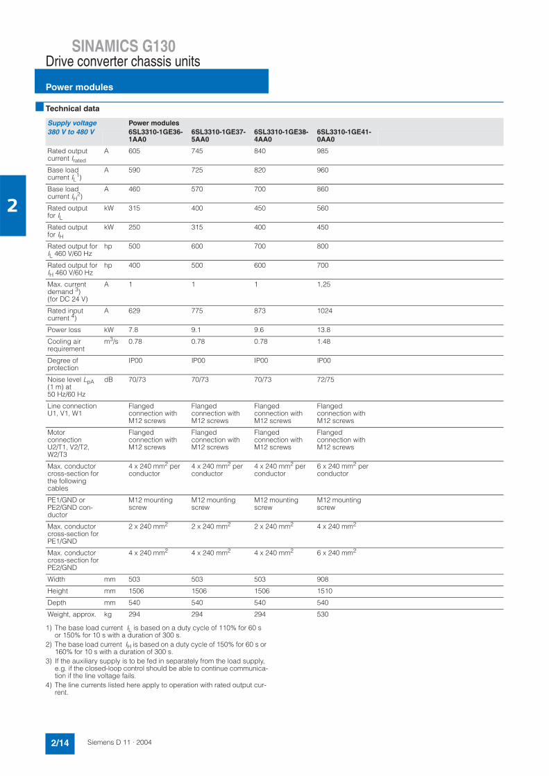
Technical data
1) The base load current IL is based on a duty cycle of 110% for 60 s or 150% for 10 s with a duration of 300 s.
2) The base load current IH is based on a duty cycle of 150% for 60 s or 160% for 10 s with a duration of 300 s.
3) If the auxiliary supply is to be fed in separately from the load supply, e.g. if the closed-loop control should be able to continue communica-tion if the line voltage fails.
4) The line currents listed here apply to operation with rated output cur-rent.
Supply voltage Power modules380 V to 480 V 6SL3310-1GE36-
1AA06SL3310-1GE37-5AA0
6SL3310-1GE38-4AA0
6SL3310-1GE41-0AA0
Rated outputcurrent Irated
A 605 745 840 985
Base load current IL
1)A 590 725 820 960
Base load current IH
2)A 460 570 700 860
Rated output for IL
kW 315 400 450 560
Rated output for IH
kW 250 315 400 450
Rated output for IL 460 V/60 Hz
hp 500 600 700 800
Rated output for IH 460 V/60 Hz
hp 400 500 600 700
Max. current demand 3)(for DC 24 V)
A 1 1 1 1,25
Rated input current 4)
A 629 775 873 1024
Power loss kW 7.8 9.1 9.6 13.8
Cooling air requirement
m3/s 0.78 0.78 0.78 1.48
Degree of protection
IP00 IP00 IP00 IP00
Noise level LpA(1 m) at 50 Hz/60 Hz
dB 70/73 70/73 70/73 72/75
Line connection U1, V1, W1
Flangedconnection with M12 screws
Flangedconnection with M12 screws
Flangedconnection with M12 screws
Flangedconnection with M12 screws
MotorconnectionU2/T1, V2/T2, W2/T3
Flangedconnection with M12 screws
Flangedconnection with M12 screws
Flangedconnection with M12 screws
Flangedconnection with M12 screws
Max. conductor cross-section for the following cables
4 x 240 mm2 per conductor
4 x 240 mm2 per conductor
4 x 240 mm2 per conductor
6 x 240 mm2 per conductor
PE1/GND or PE2/GND con-ductor
M12 mounting screw
M12 mounting screw
M12 mounting screw
M12 mounting screw
Max. conductor cross-section for PE1/GND
2 x 240 mm2 2 x 240 mm2 2 x 240 mm2 4 x 240 mm2
Max. conductor cross-section for PE2/GND
4 x 240 mm2 4 x 240 mm2 4 x 240 mm2 6 x 240 mm2
Width mm 503 503 503 908
Height mm 1506 1506 1506 1510
Depth mm 540 540 540 540
Weight, approx. kg 294 294 294 530

SINAMICS G130Drive converter chassis units
Power modules
2/15Siemens D 11 · 2004
2
Technical data (continued)
1) The base load current IL is based on a duty cycle of 110% for 60 s or 150% for 10 s with a duration of 300 s.
2) The base load current IH is based on a duty cycle of 150% for 60 s or 160% for 10 s with a duration of 300 s.
3) If the auxiliary supply is to be fed in separately from the load supply, e.g. if the closed-loop control should be able to continue communica-tion if the line voltage fails.
4) The line currents listed here apply to operation with rated output cur-rent.
Supply voltage Power modules660 V to 690 V 6SL3310-1GH33-
3AA06SL3310-1GH34-1AA0
6SL3310-1GH34-7AA0
6SL3310-1GH35-8AA0
6SL3310-1GH37-4AA0
6SL3310-1GH38-1AA0
Rated outputcurrent Irated
A 330 410 465 575 735 810
Base load current IL
1)A 320 400 452 560 710 790
Base load current IH
2)A 280 367 416 514 657 724
Rated output for IL
kW 315 400 450 560 710 800
Rated output for IH
kW 250 315 400 450 630 710
Max. current demand 3)(for DC 24 V)
A 0.9 1 1 1 1.25 1.25
Rated input current 4)
A 343 426 483 598 764 852
Power loss kW 5.8 7.5 8.5 10.3 12.8 13.9
Cooling air requirement
m3/s 0.36 0.78 0.78 0.78 1.48 1.48
Degree of protection
IP20 IP00 IP00 IP00 IP00 IP00
Noise level LpA(1 m) at 50 Hz/60 Hz
dB 69/73 70/73 70/73 70/73 73/75 73/75
Line connection U1, V1, W1
Flangedconnection with M10 screws
Flangedconnection with M12 screws
Flangedconnection with M12 screws
Flangedconnection with M12 screws
Flangedconnection with M12 screws
Flangedconnection with M12 screws
MotorconnectionU2/T1, V2/T2, W2/T3
Flangedconnection with M10 screws
Flangedconnection with M12 screws
Flangedconnection with M12 screws
Flangedconnection with M12 screws
Flangedconnection with M12 screws
Flangedconnection with M12 screws
Max. conductor cross-section for the following cables
2 x 240 mm2 per conductor
4 x 240 mm2 per conductor
4 x 240 mm2 per conductor
4 x 240 mm2 per conductor
6 x 240 mm2 per conductor
6 x 240 mm2 per conductor
PE1/GND or PE2/GNDconductor
M10 mounting screw
M12 mounting screw
M12 mounting screw
M12 mounting screw
M12 mounting screw
M12 mounting screw
Max. conductor cross-section for PE1/GND
2 x 240 mm2 2 x 240 mm2 2 x 240 mm2 2 x 240 mm2 4 x 240 mm2 4 x 240 mm2
Max. conductor cross-section for PE2/GND
2 x 240 mm2 4 x 240 mm2 4 x 240 mm2 4 x 240 mm2 6 x 240 mm2 6 x 240 mm2
Width mm 326 503 503 503 908 908
Height mm 1533 1506 1506 1506 1510 1510
Depth mm 545 540 540 540 540 540
Weight, approx. kg 162 294 294 294 530 530

SINAMICS G130Drive converter chassis unitsDC link componentsBraking modules
2/16 Siemens D 11 · 2004
2
Overview
A braking module is required if the drive will occasionally require braking or to be stopped (e.g. for EMERGENCY STOP category 1). The braking module houses the power electronics and the associated control circuit. The supply voltage for the electronics is taken from the DC link.
During operation, the DC link power is converted into heat loss in an external braking resistor.
The braking module works autonomously from the converter control. Several braking modules may be operated in parallel in order to increase the output. In this case, each braking module must have its own braking resistor.
Design
The braking module is installed in a slot inside the power mod-ule, and receives forced ventilation via the power module's fan. The braking module is connected to the DC link using the bus-bars or flexible cables supplied with the module.
The braking module features the following interfaces as stan-dard:• DC link connection• Braking resistor connection terminal• 1 x digital input (disable braking module/acknowledge faults)• 1 x digital output (fault in braking module)• PE (protective earth) connection
Selection and ordering data
Integration
Connection diagram for braking module
Suitable for power module Rated output of the power module
Order No.Braking module
Supply voltage 380 V to 480 V
6SL3310-1GE36-1AA06SL3310-1GE37-5AA06SL3310-1GE38-4AA06SL3310-1GE41-0AA0
315 kW400 kW450 kW560 kW
6SL3300-1AE32-5BA0
Supply voltage 660 V to 690 V
6SL3310-1GH33-3AA0 315 kW 6SL3300-1AH32-5AA0
6SL3310-1GH34-1AA06SL3310-1GH34-7AA06SL3310-1GH35-8AA06SL3310-1GH37-4AA06SL3310-1GH38-1AA0
400 kW450 kW560 kW710 kW800 kW
6SL3300-1AH32-5BA0
DCPA
DCNA
+ 24 V
0 V
0 V
21.6
21.5
21.4
21.3
21.2
21.1
X21
R1
R2
Braking Module
G_D011_EN_00046
Fault
Inhibit
Connection to
DC link
Shield
Fault output
Inhibit input
Connection of
braking resistor
Braking resistor

SINAMICS G130Drive converter chassis units
DC link componentsBraking modules
2/17Siemens D 11 · 2004
2
Technical data
Braking module 6SL3300-1AE32-5BA0 6SL3300-1AH32-5AA0 6SL3300-1AH32-5BA0
Line voltage of the power module 380 V to 480 V 660 V to 690 V 660 V to 690 V
P DB output kW 50
P 40 output kW 100
P 20 output (rated output) kW 200
P 15 output kW 250
Digital input
• Voltage V -3 to +30
• Low level (an open digital input is interpreted as "low")
V -3 to +5
• High level V 15 to 30
• Current consumption (typical for 24 V DC) mA 10
• Max. connectable cross-section mm2 1.5
Digital output (continuously short-circuit-proof)
• Voltage 24 V DC
• Max. load current of the digital output mA 500
• Max. connectable cross-section mm2 1.5
DC link busbar current capacity A 378 255 255
Design conforms to UL and IEC IEC IEC
Terminal/R1/R2 M8 mounting screw M8 mounting screw M8 mounting screw
Max. conductor cross-section R1/R2 mm2 50 50 50
Width mm 152 120 152
Height mm 140 130 140
Depth mm 472 500 472
Weight, approx. kg 7.5 7.3 7.5
Output
P DB Continuous braking power
P 40 = 2 x PDB 40 s output related to a braking interval of 90 s
P 20 = 4 x PDB 20 s output related to a braking interval of 90 s
P 15 = 5 x PDB 15 s output related to a braking interval of 90 s

SINAMICS G130Drive converter chassis unitsDC link componentsBraking resistors
2/18 Siemens D 11 · 2004
2
Overview
Excess power in the DC link is dissipated via the braking resistor.
The braking resistor is connected to a braking module. The max-imum distance between the braking module and the braking re-sistor must not exceed 50 mm. This means that the resulting heat loss can be dissipated outside of the switchgear room.
A 200 kW resistor is available for braking.
Greater outputs can be implemented by connecting braking modules and braking resistors in parallel. The braking resistors can be used on converters with a wide voltage range, so the voltage can be adjusted by setting the response threshold on the braking module.
A thermostat monitors the braking resistor for overheating, and if the limit value is exceeded, it is signaled via a floating contact.
Technical data
Selection and ordering data
Braking resistor 6SL3000-1BE32-5AA0 6SL3000-1BH32-5AA0
Line voltage of the power module 380 V to 480 V 660 V to 690 V
P DB output kW 50
P 40 output kW 100
P 20 output (rated output) kW 200
P 15 output kW 250
Resistor W 2.2 ±7.5% 4.9 ±7.5%
Max. current A 378 255
Max. connectable cable cross-section mm2 70
Cable gland via M50 cable gland
Line connection via M10 bolt-type terminal
Max. conductor cross-section R1/R2 mm2 50
Degree of protection IP20
Width mm 810
Height mm 1325
Depth mm 485
Weight, approx. kg 120
Braking resistor 200 kW Order No.
for supply voltage 380 V to 480 V 6SL3000-1BE32-5AA0
for supply voltage 660 V to 690 V 6SL3000-1BH32-5AA0
SINAMICS G130Drive converter chassis units
CU320 Control unit kit
2/19Siemens D 11 · 2004
2
Overview
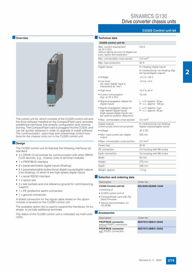
The control unit kit, which consists of the CU320 control unit and the drive software installed on the CompactFlash card, provides predefined interfaces that simplify configuration and commis-sioning. The CompactFlash card is plugged into the CU320, and can be quickly replaced in order to upgrade or install software. The communication, open-loop and closed-loop control func-tions for the chassis units run in the CU320 control unit.
Design
The CU320 control unit kit features the following interfaces as standard:• 4 x DRIVE-CLiQ sockets for communication with other DRIVE-
CLiQ devices, e.g., chassis units or terminal modules• 1 x PROFIBUS interface• 8 x parameterizable digital inputs (floating)• 8 x parameterizable bidirectional digital inputs/digital outputs
(non-floating), of which 6 are high-speed digital inputs• 1 x serial RS232 interface• 1 x option slot• 3 x test sockets and one reference ground for commissioning
support• 1 x PE (protective earth) connection• 1 x ground connection
A shield connection for the signal cable shield on the option module is located on the CU320 control unit.
The available option slot is used to expand the interfaces, for ex-ample, to include additional terminals.
The status of the CU320 control unit is indicated via multi-color LEDs.
Technical data
Selection and ordering data
Accessories
CU320 control unit kit
Max. current requirement (at 24 V DC)without taking account of digital out-puts, option slot expansion
0.8 A
Max. connectable cross-section 2.5 mm2
Max. fuse protection 20 A
Digital inputs 8 x floating digital inputs8 x bidirectional non-floating digi-tal inputs/digital outputs
• Voltage -3 V to +30 V
• Low level(an open digital input is interpreted as "low")
-3 V to +5 V
• High level 15 V to 30 V
• Current consumption(typ. at 24 V DC)
10 mA
• Signal propagation delays for digital inputs
L → H: approx. 50 µsH → L: approx. 100 µs
• Signal propagation delays for high-speed digital inputs(high-speed digital inputs can be used for position detection)
L → H: approx. 5 µsH → L: approx. 50 µs
• Max. connectable cross-section 0.5 mm2
Digital outputs (continuously short-circuit-proof)
8 x bidirectional non-floating digital outputs/digital inputs
• Voltage 24 V DC
• Max. load current per digital output
500 mA
• Max. connectable cross-section 0.5 mm2
Power loss 20 W
PE connection On housing with M5 screw
Earth connection On housing with M5 screw
Width 50 mm
Height 270 mm
Depth 226 mm
Weight, approx. 1.5 kg
Description Order No.
CU320 Control unit kitconsisting of :• CU320 control unit kit• CompactFlash card with the
latest firmware• Device documentation on
CD-ROM
6SL3040-0GA00-1AA0
Description Order No.
PROFIBUS connectorwithout PG/PC connection
6ES7972-0BA41-0XA0
PROFIBUS connectorwith PG/PC connection
6ES7972-0BB41-0XA0

SINAMICS G130Drive converter chassis units
CU320 Control unit kit
2/20 Siemens D 11 · 2004
2
Integration
Communication between a CU320 control unit and the connected components takes place via DRIVE-CLiQ.
Connection diagram for CU320 control unit kit
+
R x
D
T x
D
M
MX103X102
1
X101X100
PROFIBUS
X126
DR
IVE
-CLi
Q
DR
IVE
-CLi
Q
0
DR
IVE
-CLi
Q
2
DR
IVE
-CLi
Q
3
M
+
3)
3)
532
2)
2)
DI 0
X122
4
3
2
1
DI 1
DI 3
DI 2
5M 1
M6
DI/DO 8 7
8
9
10
11
12
DI/DO 9
DI/DO 10
DI/DO 11
M
M
DI 4
X132
4
3
2
1
DI 5
DI 7
DI 6
5M 2
M6
DI/DO 12 7
8
9
10
11
12
DI/DO 13
DI/DO 14
DI/DO 15
M
M
+ 24 V
M
X124
M
+
M
+
M
1)
1)
1)
1)
1)
1)
X140
Control UnitCU320
1) Fast inputs (must be shielded)2) Jumper open, isolation for digital inputs (DI)3) Can be parameterized individually as input/output
G_D
212_
EN
_000
27c
Serial interface
ext.
24 V
sock
et
sock
et
sock
et
sock
et

SINAMICS G130Drive converter chassis units
Supplementary system componentsTB30 terminal board
2/21Siemens D 11 · 2004
2
Overview
The TB30 terminal board expands the number of digital in-puts/digital outputs and analog inputs/analog outputs of the CU320 control unit.
Design
The following are located on the TB30 terminal board:• Power supply for digital inputs/digital outputs• 4 x digital inputs• 4 x digital outputs• 2 x analog inputs• 2 x analog outputs
The TB30 terminal board plugs into the option slot on the CU320 control unit.
A shield connection for the signal cable shield is located on the CU320 control unit.
Technical data
Selection and ordering data
TB30 terminal board
Max. current requirement (at 24 V DC) via CU320 control unit without taking account of digital outputs
0.05 A
Max. connectable cross-section 2.5 mm2
Max. fuse protection 20 A
Digital inputs
• Voltage -3 V to +30 V
• Low level(an open digital input is interpreted as "low")
-3 V to +5 V
• High level 15 V to 30 V
• Current consumption(at 24 V DC)
typ. 10 mA
• Signal propagation delays for digital inputs
L → H: approx. 50 µsH → L: approx. 100 µs
• Max. connectable cross-section 0.5 mm2
Digital outputs (continuously short-circuit-proof)
• Voltage 24 V DC
• Max. load current per digital out-put
500 mA
• Max. connectable cross-section 0.5 mm2
Analog inputs (differential)
• Voltage range(an open analog input is interpreted as 0 V)
-10 V to +10 V
• Internal resistance Ri 65 kΩ
• Resolution 13 bit + sign
• Max. connectable cross-section 0.5 mm2
Analog outputs (continuously short-circuit-proof)
• Voltage range -10 V to +10 V
• Max. load current -3 mA to +3 mA
• Resolution 11 bit + sign
• Max. connectable cross-section 0.5 mm2
Power loss < 3 W
Weight, approx. 0.1 kg
Description Order No.
TB30 terminal board 6SL3055-0AA00-2TA0

SINAMICS G130Drive converter chassis unitsSupplementary system componentsTB30 terminal board
2/22 Siemens D 11 · 2004
2
Integration
Connection diagram for TB30 terminal board
+ M
+ 24 V
M
X424
M
+
M
+
M
V
V
AI 0+
AI 0-
AI 1 -
AI 1+
AO 0+
AO 0-
AO 1+
AO 1-
X4821
8
4
3
2
1
5
6
7
8
± 10 V
X48111
DI 0
DI 1
DI 3
DI 2
DO 0
8
DO 1
DO 2
DO 3
4
3
2
5
6
7
8
G_D
212_
XX
_000
28b
M
+ext.
24 V
Terminal BoardTB30

SINAMICS G130Drive converter chassis units
Supplementary system componentsTM31 terminal module
2/23Siemens D 11 · 2004
2
Overview
With the TM31 terminal module, the number of available digital inputs and outputs and the number of analog inputs and outputs within a drive can be expanded.
Design
The following interfaces are located on the TM31 terminal mod-ule:• 8 x digital inputs• 4 x bidirectional digital inputs/digital outputs• 2 x relay outputs with changeover contact• 2 x analog inputs• 2 x analog outputs• 1 x temperature sensor input (KTY84-130 or PTC)• 2 x DRIVE-CLiQ sockets• 1 x connection for the electronics power supply via the 24 V
DC power supply connector• 1 x PE (protective earth) connection
The TM31 terminal module can be snapped onto a 35×15/7.5DIN rail to EN 50 022.
The signal line shield can be connected to the TM31 terminal module via a shield connection terminal, e.g., Phoenix Contact Type SK8 or Weidmüller type KLBÜ CO 1. The shield connection terminal must not be used for strain relief.
The status of the TM31 terminal module is indicated via a multi-color LED.
Selection and ordering data
Technical data
Description Order No.
TM31 terminal module(without DRIVE-CLiQ cable)
6SL3055-0AA00-3AA0
TM31 terminal module
Max. current requirement (at 24 V DC) without taking account of digital outputs
0.5 A
Max. connectable cross-section 2.5 mm2
Max. fuse protection 20 A
Digital inputs
• Voltage -3 V to +30 V
• Low level (an open digital input is interpreted as "low")
-3 V to +5 V
• High level 15 V to 30 V
• Current consumption (at 24 V DC) typ. 10 mA
• Signal propagation delays for digital inputs
L → H: approx. 50 µsH → L: approx. 100 µs
• Max. connectable cross-section 1.5 mm2
Digital outputs (continuously short-circuit-proof)
• Voltage 24 V DC
• Max. load current per digital output 100 mA
• Max total current of digital outputs 400 mA
• Max. connectable cross-section 1.5 mm2
Analog inputs (a switch is used to toggle between voltage and current input)
• As voltage input
- Voltage range -10 V to +10 V
- Internal resistance Ri 100 kΩ
• As current input
- Current range 4 mA to 20 mA/-20 mA to +20 mA/ 0 mA to 20 mA
- Internal resistance Ri 250 Ω
- Resolution 11 bit + sign
• Max. connectable cross-section 1.5 mm2
Analog outputs (continuously short-circuit-proof)
• Voltage range -10 V to +10 V
• Max. load current -3 mA to +3 mA
• Current range 4 mA to 20 mA, -20 mA to +20 mA, 0 mA to 20 mA
• Max. load resistance 500 Ω for outputs in the range -20 mA to +20 mA
• Resolution 11 bit + sign
• Max. connectable cross-section 1.5 mm2
Relay outputs (change-over contacts)
• Max. load current 8 A
• Max. switching voltage 250 V AC, 30 V DC
• Max. switching power (at 250 V AC ) 2000 VA (cos ϕ = 1)750 VA (cos ϕ = 0.4)
• Max. switching power (at 30 V DC ) 240 W (ohmic load)
• Required minimum current 100 mA
• Max. connectable cross-section 2.5 mm2
Power loss < 10 W
PE connection On housing with M4 screw
Width 50 mm
Height 150 mm
Depth 111 mm
Weight, approx. 0.87 kg
SINAMICS G130Drive converter chassis unitsSupplementary system componentsTM31 terminal module
2/24 Siemens D 11 · 2004
2
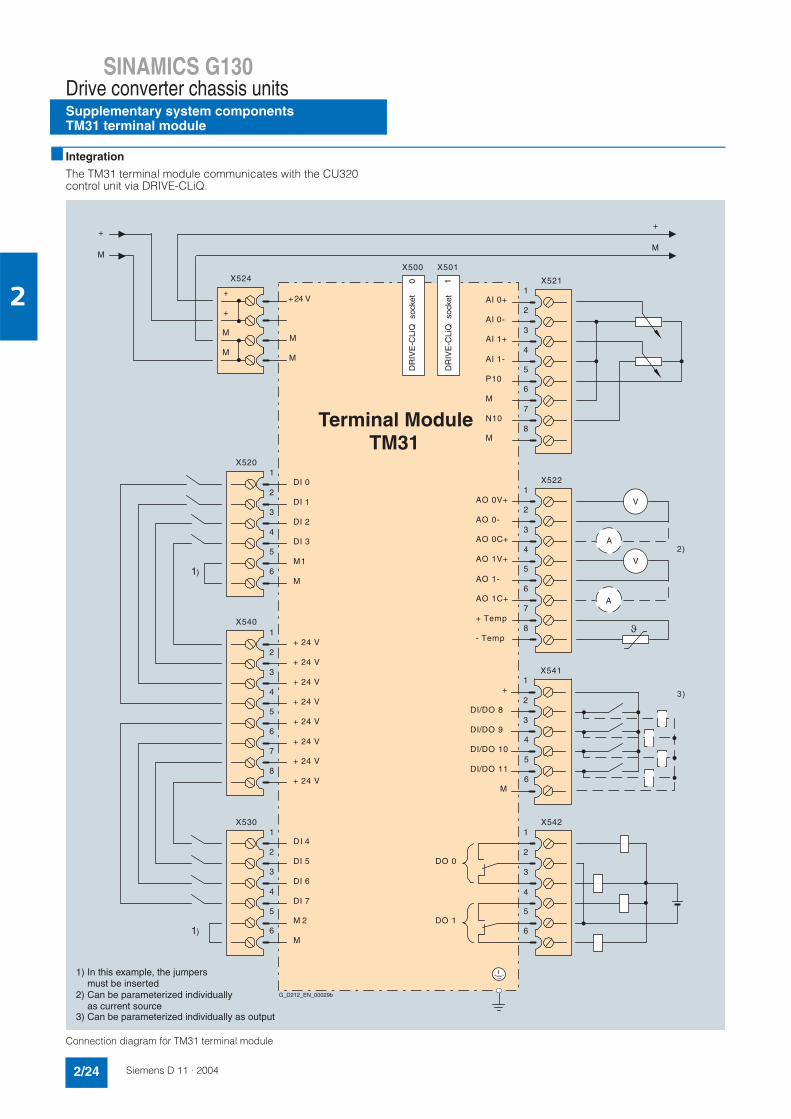
Integration
The TM31 terminal module communicates with the CU320 control unit via DRIVE-CLiQ.
Connection diagram for TM31 terminal module
X501X500
DI 0
4
3
2
1
DI 1
DI 3
DI 2
5M1
6M
X520
+ 24 V
4
3
2
1
+ 24 V
+ 24 V
+ 24 V
5+ 24 V
+ 24 V6
+ 24 V7
8+ 24 V
X540
DI 4
4
3
2
1
DI 5
DI 7
DI 6
5M 2
6M
X530
1)
1)
AI 0+
4
3
2
1
AI 0-
AI 1-
AI 1+
5P10
6M
X521
7N10
M8
AO 0V+
4
3
2
1
AO 0-
AO 1V+
AO 0C+
5AO 1-
6AO 1C+
X522
7+ Temp
- Temp8
V
V
4
3
2
1
DO 0
5DO 1
6
X542
+ 24 V
M
X524
M
+
M
+
M
M
+
M
+
X541
DI/DO 8
1
2
3
4
5
6
DI/DO 9
DI/DO 11
+
DI/DO 10
M
2)
3)
1
DR
IVE
-CLi
Q
DR
IVE
-CLi
Q
0
A
A
Terminal ModuleTM31
1) In this example, the jumpers must be inserted
2) Can be parameterized individually
Can be parameterized individually as outputas current source
3)
G_D212_EN_00029b
so
cket
sock
et

SINAMICS G130Drive converter chassis units
Supplementary system componentsSMC30 sensor module cabinet-mounted
2/25Siemens D 11 · 2004
2
Overview
The SMC30 sensor module cabinet-mounted is required when a motor with a DRIVE-CLiQ interface is not available or when ex-ternal encoders are required in addition to the motor encoder.
TTL/HTL incremental encoders with and without cable-break detection are supported.
The motor temperature can also be detected using KTY84-130 PTC sensors.
Design
The SMC30 sensor module cabinet-mounted features the follow-ing interfaces as standard:• 1 x DRIVE CLiQ interface• 1 x encoder connection including motor temperature detection
(KTY84-130) via SUB-D connector or terminals• 1 x connection for the electronics power supply via the 24 V DC
power supply connector• 1 x PE (protective earth) connection
The status of the SMC30 sensor module cabinet-mounted is in-dicated via a multi-color LED.
SMC30 sensor modules cabinet-mounted can be snapped onto a 35×15/7.5 DIN rail to EN 50 022.
The maximum encoder cable length between SMC30 modules and encoders is 100 m. For HTL encoders, this length can be in-creased to 300 m if signals A+/A- and B+/B- are evaluated and the power supply cable has a minimum cross-section of 0.75 mm2.
The signal cable shield can be connected to the SMC30 sensor module cabinet-mounted via a shield connection terminal, e.g., Phoenix Contact type SK8 or Weidmüller type KLBÜ CO 1. The shield connection terminal must not be used for strain relief.
Integration
The SMC30 sensor module cabinet-mounted communicates with the CU320 control unit via DRIVE-CLiQ.
Technical data
Selection and ordering data
SMC30 sensor module cabinet-mounted
Max. current requirements (at 24 V DC) without taking account of encoder
0.6 A
Max. connectable cross-section 2.5 mm2
Max. fuse protection 20 A
Power loss < 10 W
PE connection On housing with M4 screw
Width 50 mm
Height 150 mm
Depth 111 mm
Weight, approx. 0.8 kg
Description Order No.
SMC30 sensor module cabinet-mounted (without DRIVE-CLiQ cable)
6SL3055-0AA00-5CA0

SINAMICS G130Drive converter chassis unitsSupplementary system componentsAOP30 advanced operator panel
2/26 Siemens D 11 · 2004
2
Overview
The AOP30 advanced operator panel is an optional input/output device for converters from the SINAMICS G130 series. On the SINAMICS G150 drive converter cabinet units, it is fitted in the cabinet doors as standard.
It has the following features and characteristics:• Graphical LCD display with backlighting for plain-text display
and a bar display of process variables• LEDs for displaying the operational status• Help function describing causes of and remedies for faults
and alarms• Keypad for operational control of a drive• Local/remote switchover for selecting the input point (priority
assigned to operator panel or customer's terminal block / PROFIBUS)
• Numeric keypad for input of setpoint or parameter values• Function keys for prompted navigation in the menu• Two-stage safety strategy to protect against accidental or un-
authorized changes to settings.Operation of the drive from the operator panel can be dis-abled by a password, ensuring that only parameter values and process variables can be displayed in the panel. A pass-word can be used to prevent the unauthorized modification of converter parameters.
• IP54 degree of protection (when installed).
The AOP30 and SINAMICS drive communicate via an RS 232 serial interface with PPI protocol. A null modem cable can be used to connect them.
The AOP30 may be omitted if the drive is only operated via PROFIBUS, for example, and no local display is required on the cabinet. The AOP30 can then be used simply for commissioning purposes and to obtain diagnostic information, in which case it will be plugged into the RS 232 interface on the CU320 control unit.
An external 24 V power supply (max. power consumption 200 mA) is needed to run the AOP30. This can be tapped off from the power supply of the power module (see also Engineer-ing information).
Design
The AOP30 is an operator panel with graphical display and membrane keyboard. An RS 232 port is used as the interface to the drive unit. The unit is suitable for installation in control cabi-net doors that are 2 mm to 4 mm thick.
Features:• Green backlit display, 240 x 64 pixels resolution• Membrane keyboard with 26 keys• Connection for an external 24 V supply• RS 232 interface• Time and date stored by an internal buffer battery• 3 LEDs to signal the operating state of the drive:
- RUN (green)- ALARM (yellow)- FAULT (red)
Function
The current operating states, setpoints and actual values, pa-rameters, indices, faults and alarms are displayed in the display panel.
The basic operator panel language is English. Further lan-guages may be optionally selected as the second language.
Selection and ordering data
Accessories
AOP30 advanced operator panel Order No.
with display languages English/German
6SL3055-0AA00-4CA0
with display languages English/Italian
6SL3055-0AA00-4CC0
with display languages English/French
6SL3055-0AA00-4CD0
with display languages English/Spanish
6SL3055-0AA00-4CE0
RS 232 plug-in cable Order No.
Length 1 m 6FX8002-1AA01-1AB0
Length 2 m 6FX8002-1AA01-1AC0
Length 3 m 6FX8002-1AA01-1AD0
Length 4 m 6FX8002-1AA01-1AE0
Length 5 m 6FX8002-1AA01-1AF0
Length 6 m 6FX8002-1AA01-1AG0
Length 7 m 6FX8002-1AA01-1AH0
Length 8 m 6FX8002-1AA01-1AJ0
Length 9 m 6FX8002-1AA01-1AK0
Length 10 m 6FX8002-1AA01-1BA0

SINAMICS G130Drive converter chassis units
Signal cables
2/27Siemens D 11 · 2004
2
Overview
Communication between the CU320 control unit, the power module and other active SINAMICS components takes place via DRIVE-CLiQ - the drive's internal serial interface. Preassembled cables are available for this purpose.
MOTION-CONNECT DRIVE-CLiQ cables
Preassembled MOTION-CONNECT cables for DRIVE-CLiQ are available precut to length in order to connect the control units to the power modules and terminals.
The DRIVE-CLiQ cable needed to connect the power module to the control unit is already supplied, together with the 24 V supply cable, with the power module.
Application
The DRIVE-CLiQ cables are only suitable for wiring DRIVE-CLiQ components that have an external 24 V DC power supply.
Serial plug-in cable for connecting the AOP30 to the CU320
The AOP30 operator panel is connected to the CU320 control unit via a serial plug-in cable (RS 232 cable).
The maximum cable length is 10 m. To guarantee uninterrupted communication, a shielded cable is recommended, and the ca-ble shield should be connected to both connector housings.
Selection and ordering data
Integration
Connection example - CU320 control unit
Signal cable Lengthm
Order No.
Preassembled DRIVE-CLiQ cableDegree of protection of connector IP20/IP20
0.11 6SL3060-4AB00-0AA0
0.16 6SL3060-4AD00-0AA0
0.21 6SL3060-4AF00-0AA0
0.26 6SL3060-4AH00-0AA0
0.36 6SL3060-4AM00-0AA0
0.60 6SL3060-4AU00-0AA0
0.95 6SL3060-4AA10-0AA0
1.20 6SL3060-4AW00-0AA0
1.45 6SL3060-4AF10-0AA0
2.80 6SL3060-4AJ20-0AA0
5.00 6SL3060-4AA50-0AA0
Preassembled RS 232 plug-in cable for connecting the AOP30 to the CU320
1 6FX8002-1AA01-1AB0
2 6FX8002-1AA01-1AC0
3 6FX8002-1AA01-1AD0
4 6FX8002-1AA01-1AE0
5 6FX8002-1AA01-1AF0
6 6FX8002-1AA01-1AG0
7 6FX8002-1AA01-1AH0
8 6FX8002-1AA01-1AJ0
9 6FX8002-1AA01-1AK0
10 6FX8002-1AA01-1BA0
6FX8002-1AA1-1XX0
6SL3060-4A 0-0AA0
-X500
6SL3060-4A 0-0AA0 *)
6SL3060-4A 0-0AA0
-X101
-X140 -X540
-X501
-X500
-X501
-X400
-X401
CU320controlunit
AOP30operatorpanel
TM31terminalmodule
TM31terminalmodule
Powermodule
*) This DRIVE-CLiQ cable is supplied with the power module. G_
D0
11
_E
N_
00
04
3
SINAMICS G130Drive converter chassis units
Notes
2/28 Siemens D 11 · 2004
2
Siemens D 11 · 2004
3/2 Overview
3/2 Benefits
3/2 Application
3/3 Design
3/4 Function3/4 AOP30 operator panel3/5 Communication with higher-level
control and customer's terminal block
3/5 Open-loop and closed-loop control functions
3/5 Software and protection functions
3/6 Technical data3/8 Derating data3/9 Overload capability3/8 EMC information
3/9 Selection and ordering data3/10 Weights and dimensions
3/11 Accessories
3/12 Options3/14 Option selection matrix3/15 Ordering examples3/16 Description of options
SINAMICS G150Drive converter cabinet units
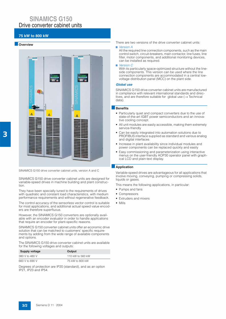
SINAMICS G150Drive converter cabinet units
75 kW to 800 kW
3/2 Siemens D 11 · 2004
3
Overview
SINAMICS G150 drive converter cabinet units, version A and C
SINAMICS G150 drive converter cabinet units are designed for variable-speed drives in machine building and plant construc-tion.
They have been specially tuned to the requirements of drives with quadratic and constant load characteristics, with medium performance requirements and without regenerative feedback.
The control accuracy of the sensorless vector control is suitable for most applications, and additional actual speed value encod-ers are therefore superfluous.
However, the SINAMICS G150 converters are optionally avail-able with an encoder evaluator in order to handle applications that require an encoder for plant-specific reasons.
SINAMICS G150 converter cabinet units offer an economic drive solution that can be matched to customers' specific require-ments by adding from the wide range of available components and options.
The SINAMICS G150 drive converter cabinet units are available for the following voltages and outputs:
Degrees of protection are IP20 (standard), and as an option IP21, IP23 and IP54.
There are two versions of the drive converter cabinet units:7 Version A
All the required line connection components, such as the main control switch, circuit-breakers, main contactor, line fuses, line filter, motor components, and additional monitoring devices, can be installed as required.
7 Version CWith its particularly space-optimized structure without the line-side components. This version can be used where the line connection components are accommodated in a central low-voltage distribution panel (MCC) on the plant side.
Global use
SINAMICS G150 drive converter cabinet units are manufactured in compliance with relevant international standards and direc-tives, and are therefore suitable for global use (→ Technical data).
Benefits
• Particularly quiet and compact converters due to the use of state-of-the-art IGBT power semiconductors and an innova-tive cooling concept.
• All unit modules are easily accessible, making them extremely service-friendly
• Can be easily integrated into automation solutions due to PROFIBUS interface supplied as standard and various analog and digital interfaces
• Increase in plant availability since individual modules and power components can be replaced quickly and easily
• Easy commissioning and parameterization using interactive menus on the user-friendly AOP30 operator panel with graph-ical LCD and plain-text display.
Application
Variable-speed drives are advantageous for all applications that involve moving, conveying, pumping or compressing solids, liquids or gases.
This means the following applications, in particular:• Pumps and fans• Compressors• Extruders and mixers• Mills
Supply voltage Output
380 V to 480 V 110 kW to 560 kW
660 V to 690 V 75 kW to 800 kW

SINAMICS G150Drive converter cabinet units
75 kW to 800 kW
3/3Siemens D 11 · 2004
3
Design
SINAMICS G150 drive converter cabinet units are characterized by their compact, modular, and service-friendly design.
A wide range of options is available depending on the cabinet version which permit optimum adaptation of the drive system to the respective requirements (→ Options).
Example of design of a SINAMICS G150 drive converter cabinet unit, version A
Basic design of a SINAMICS G150 drive converter cabinet unit with a number of version-specific options
!"#
$ "##"%"%" &'()
""
&##
"#*+
*#&,,!
-
-
-
,./
0112134
,#
#
#
- +"&,&&56+7"#*+6&##"%7""","%4!"& 4"8

SINAMICS G150Drive converter cabinet units
75 kW to 800 kW
3/4 Siemens D 11 · 2004
3
Function
AOP30 operator panel
An operator panel is located in the cabinet door of the converter for operation, monitoring and commissioning tasks.
The AOP30's two-stage safety concept prevents unintentional or unauthorized changes to settings. The keyboard lock disables operation of the drive from the operator panel, so that only pa-rameter values and process variables can be displayed. The OFF key is factory-set to "active" but can also be "deactivated" by the customer. A password can be used to prevent the unau-thorized modification of converter parameters.
The user is guided through the screens for commissioning the drive by the menu-driven display. Only 6 motor parameters (which can be found on the motor rating plate) have to be en-tered when the AOP30 is started up for the first time. The control is then optimized automatically to fine-tune the converter to the motor.
The plain text for the display is saved in two languages, and the currently desired language can be selected using parameters (English/German as standard, see options for other languages).
The following pictures show examples of plain text displays in various operating phases.
The first commissioning is carried out using the operator panel.
Only 6 motor parameters have to be entered:
Output, speed, current, cos ϕ, voltage and frequency of the mo-tor.
This information can be found on the motor rating plate, and is entered into the screens on the display by following a short, menu-driven procedure. The type of motor cooling must be en-tered in addition.
The next screen contains the parameter values that are used to automatically optimize the control.
During running, current data are indicated on the display as ab-solute values, such as setpoint and actual values, or it is possi-ble to parameterize up to 3 process variables as a quasi-analog bar display.
Any alarms which occur are indicated by flashing of the yellow "ALARM" LED, while faults are signaled by a lit red "FAULT" LED. There is also an indication of the cause displayed in plain text on the display's status line.
Commissioning / Service
Device commissioningAOP settingsAOP diagnosis
Help Back Select.
G_
D0
11
_e
n_
00
04
7
Drive commissioning
Motor dataBackp0304 MOT.U_rated 400.0 Vp0305 MOT. I_rated 405.0 Ap0307 MOT.P_rated 235.0 kWp0308 MOT.CosPhi_ rated 0.870
Help Change OK G_D
011_
en_0
0048
Basic commissioningBackp0700 Pre-assignment BI 6: S/G150 TM 31p1000 Default DI n_set 2: TM 31_AIOp1080 Minimum speed 0.000 rpmp1082 Maximum speed 1500.000 rpm
Help Change OK G_
D0
11
_e
n_
00
04
9
! "
#
$
%
#
g_D
011_
_en_
0001
1b
%
$
&
&
#
#
! "
g_D
011_
en_0
0012
b
Current fault in: 1234.04:25:30
F 07901 Motor overspeed
Help Alt Back Ack.
GD
011
EN
00
05
0
Motor overspeedFlt. val = 0000000000 00000000 (hex)The maximum permissible positive ornegative speed has been exceeded.The maximum permissible positive speedis calculated as follows:Minimum (p1082, CI: p1085) + p2162Back G
_D
011
_e
n_
00
05
1

SINAMICS G150Drive converter cabinet units
75 kW to 800 kW
3/5Siemens D 11 · 2004
3
Function (continued)
Communication with higher-level control and customer's terminal block
A PROFIBUS interface on the CU320 control unit and the TM31 terminal module is provided as standard for use as the customer interface.
You can use this customer terminal block to connect the system to the higher-level controller using analog and digital signals, or to connect additional units.
To simplify configuration and commissioning of the drive, the TM31 terminal module is supplied with factory default settings (→ Engineering information).
Open-loop and closed-loop control functions
The converter closed-loop control contains a high-quality sen-sorless vector control with speed and current controls as well as motor and converter protection.
Software and protection functions
The software functions available as standard are described be-low:
1) Factory setting: not activated (can be programmed)
Software and protection functions Description
Setpoint input The setpoint can be defined internally or externally, internally as a fixed, motorized potentiometer or jog setpoint, externally via the PROFIBUS interface or an analog input of the customer terminal block. The internal fixed setpoints and the motorized potentiometer setpoint can be switched over or adjusted using control commands via all interfaces.
Motor identification Automatic motor identification permits fast and simple commissioning and optimization of the drive con-trol.
Ramp-function generator A user-friendly ramp-function generator with separately adjustable ramp-up and ramp-down times, together with variable smoothing times in the lower and upper speed ranges, improve the control response and therefore prevent mechanical overloading of the drive train. The ramp-down ramps can be parameterized separately for emergency stop.
Vdc max controller The Vdc max controller automatically prevents overvoltages in the DC link if the set ramp-down ramp is too short, for example. This can also extend the set ramp-down time.
Kinetic buffering (KIP) Power supply failures are bridged to the extent permitted by the kinetic energy of the drive train. The speed drops depending on the moment of inertia and the load torque. The current speed setpoint is resumed when the power supply returns.
Automatic restart 1) The automatic restart switches the drive on again when the power is restored after a power failure, and ramps up to the current speed setpoint.
Flying restart 1) The flying restart permits connection of the converter to a rotating motor.
I²t detection for motor protection The motor temperature is calculated in a motor model stored in the converter software, taking into account the current speed and load. More exact recording of the temperature, also taking into account the influence of the ambient temperature, is possible by means of direct temperature recording using KTY84 sensors in the motor winding.
Evaluation of motor temperature Motor protection by evaluating a KTY84 or PTC temperature sensor. When a KTY84 sensor is connected, the limit values can be set for alarm or shutdown. When connecting a PTC thermistor, the reaction follow-ing triggering of it (alarm or shutdown) can be defined.
Motor blocking protection A blocked motor is recognized and protected against thermal overloading by shutting down.
Power section protection
Earth fault monitoring on the output side
An earth fault on the output side is recognized by a total current monitor, and results in shutdown in earthed-neutral systems.
Electronic short-circuit protection on the output side
A short-circuit between motor and converter (on the converter output terminals, in the motor cable, in the terminal box) is detected and switched off.
Thermal overload protection A warning message is issued first when the overtemperature threshold responds. If the temperature rises further, either a shutdown is carried out or automatic influencing of the pulse frequency or output current so that a reduction in the thermal load is achieved. Following elimination of the cause of the fault (e.g. improvement in the ventilation), the original operating values are automatically resumed.

SINAMICS G150Drive converter cabinet units
75 kW to 800 kW
3/6 Siemens D 11 · 2004
3
Technical data
Deviations from the defined classes are identified by underlining.
Electrical data
Supply voltages and output ranges 380 V to 480 V 3 AC, ±10% (-15% < 1 min) 110 kW to 560 kW660 V to 690 V 3 AC, ±10% (-15% < 1 min) 75 kW to 800 kW
Supply systems TN/TT supplies or isolated supplies (IT supplies)
Line frequency 47 Hz to 63 Hz
Output frequency 0 Hz to 300 Hz
Power factor- Fundamental mode- Total
> 0.980.93 to 0.96
Converter efficiency > 98%
Control method Vector control with and without sensor or V/f control
Fixed speeds 15 fixed speeds plus 1 minimum speed, programmable (in the default setting 3 fixed setpoints plus 1 minimum speed can be selected via the terminal block / PROFIBUS)
Skipped frequency ranges 4, programmable
Setpoint resolution 0.001 rpm digital12 bit analog
Braking operation optional via braking unit
Mechanical data
Degree of protection IP20 (higher degrees of protection up to IP54 optional)
Protection class Acc. to EN 50 178 Part 1
Type of cooling Forced air ventilation
Noise level LpA (1 m) ≤ 72 dB at 50 Hz line frequency
Shock protection BGV A2
Cabinet system Rittal TS 8, doors with double-barb lock, three-section base plates for cable entry
Paint RAL 7035 (indoor requirements)
Compliance with standards
Standards EN 60 146-1, EN 61 800-2, EN 61 800-3, EN 50 178, EN 60 204-1, EN 60 529
CE marking According to EMC directive No. 89/336/EC and low voltage directive No. 73/23/EC
RI suppression According to EMC product standard for variable-speed drives EN 61 800-3, "second environment"."First environment" available upon request
Operation Storage Transport
Ambient conditions
Ambient temperature 0 °C to +40 °CUp to +50 °C: see derating data
-25 °C to +55 °C -25 °C to +70 °Cabove -40 °C: for 24 hours
Relative humidity(non-condensing)
5% to 95%corresponds to 3K3 to IEC 60 721-3-3
5% to 95%corresponds to 1K4 to IEC 60 721-3-1
5% to 95% at 40 °Ccorresponds to 2K3 to IEC 60 721-3-2
Installation altitude Up to 2000 m above sea level without reduction in performance, > 2000 m: see derating data
Mechanical stability
Vibratory load
- Deflection- Acceleration
0.075 mm at 10 Hz to 58 Hz10 m/s2 at > 58 Hz to 200 Hz-
1.5 mm at 5 Hz to 9 Hz5 m/s² at > 9 Hz to 200 Hz corresponds to 1M2 to IEC 60 721-3-1
3.1 mm at 5 Hz to 9 Hz10 m/s² at > 9 Hz to 200 Hz corresponds to 2M2 to IEC 60 721-3-2
Shock load
- Acceleration 100 m/s2 at 11 mscorresponds to 3M4 to IEC 60 721-3-3
40 m/s² at 22 mscorresponds to 1M2 to IEC 60 721-3-1
100 m/s² at 11 mscorresponds to 2M2 to IEC 60 721-3-2

SINAMICS G150Drive converter cabinet units
75 kW to 800 kW
3/7Siemens D 11 · 2004
3
Technical data (continued)
Derating data
Compensation of current derating as a function of installation al-titude / ambient temperature
If the converters are operated at an installation altitude > 2000 m above sea level, the maximum permissible output cur-rent can be calculated using the following tables according to the degree of protection selected for the cabinet unit. The spec-ified values already include a permitted correction between in-stallation altitude and ambient temperature (incoming air tem-perature at the inlet to the converter cabinet unit).
Current derating depending on ambient temperature (temperature of inlet air) and installation altitude for cabinet units with degree of protection IP20, IP21 and IP23
Current derating depending on ambient temperature (temperature of inlet air) and installation altitude for cabinet units with degree of protection IP54
Voltage derating as a function of the installation altitude
In addition to the current derating, the voltage derating must be considered according to the following table with installationaltitudes > 2000 m above sea level.
Voltage derating as a function of the installation altitude
Installation alti-tude above sea levelm
Current deratingat an ambient temperature of
20 °C 25 °C 30 °C 35 °C 40 °C 45 °C 50 °C
0-2000 95.0% 87.0%
2001-2500 96.3% 91.4% 83.7%
2501-3000 100% 96.2% 92.5% 87.9% 80.5%
3001-3500 96.7% 92.3% 88.8% 84.3% 77.3%
3501-4000 97.8% 92.7% 88.4% 85.0% 80.8% 74.0%
Installation alti-tude above sea levelm
Current deratingat an ambient temperature of
20 °C 25 °C 30 °C 35 °C 40 °C 45 °C 50 °C
0-2000 95.0% 87.5% 80.0%
2001-2500 100% 96.3% 91.4% 84.2% 77.0%
2501-3000 96.2% 92.5% 87.9% 81.0% 74.1%
3001-3500 96.7% 92.3% 88.8% 84.3% 77.7% 71.1%
3501-4000 97.8% 92.7% 88.4% 85.0% 80.8% 74.7% 68.0%
Installation altitude above sea level
Voltage deratingfor a rated input voltage of
Voltage deratingfor a rated input voltage of
m 380 V 400 V 420 V 440 V 460 V 480 V 660 V 690 V
0-2000 100%
2001-2250 96% 96%
2251-2500 98% 94% 98% 94%
2501-2750 100% 98% 94% 90% 95% 90%
2751-3000 95% 91% 88% 92% 88%
3001-3250 97% 93% 89% 85% 89% 85%
3251-3500 98% 93% 89% 85% 82% 85% 82%
3501-3750 95% 91% 87% 83% 79% - -
3751-4000 96% 92% 87% 83% 80% 76% - -

SINAMICS G150Drive converter cabinet units
75 kW to 800 kW
3/8 Siemens D 11 · 2004
3
Technical data (continued)
Overload capability
The SINAMICS G150 drive converter cabinet units are equipped with an overload reserve to deal with breakaway torques, for ex-ample. If larger surge loads occur, this must be taken into ac-count when configuring. In drives with overload requirements, the appropriate base load current must therefore be used as a basis for the required load.
The criterion for overload is that the drive is operated with its base load current before and after the overload occurs, and a load duration of 300 s is assumed.
The base load current IL for a small overload is based on a duty cycle of 110% for 60 s or 150% for 10 s.
The base load current IH for a high overload is based on a duty cycle of 150% for 60 s or 160% for 10 s.
Small overload
High overload
EMC information
The electromagnetic compatibility describes - according to the definition of the EMC directive - the "capability of a device to work satisfactorily in the electromagnetic environment without it-self causing electromagnetic interferences which are unaccept-able for other devices present in this environment". To guarantee that the appropriate EMC directives are observed, the devices must demonstrate a sufficiently high noise immunity, and also the emitted interference must be limited to acceptable values.
The EMC requirements for "Variable-speed drive systems" are described in the product standard EN 61 800-3. A variable-speed drive system (or power drive system PDS) consists of the drive converter and the electric motor including cables. The driven machine is not part of the drive system. EN 61 800-3 de-fines different limits depending on the location of the drive sys-tem, referred to as the first and second environments.
The first environment comprises living accommodation or loca-tions where the drive system is directly connected to the public low-voltage network without an intermediate transformer.
The second environment is understood to be all locations out-side living areas. These are basically industrial areas which are powered from the medium-voltage network via their own trans-formers.
Four different categories are defined in EN 61 800-3 Ed.2 de-pending on the location and the power of the drive:
Category C1: Drive systems for rated voltages < 1000 V for un-limited use in the first environment.
Category C2: Stationary drive systems for rated voltages < 1000 V for use in the second environment. Use in the first en-vironment is possible if the drive system is installed and used by qualified personnel. The warning and installation information supplied by the manufacturer must be observed.
Category C3: Drive systems for rated voltages < 1000 V for ex-clusive use in the second environment.
Category C4: Drive systems for rated voltages ≥ 1000 V or for rated currents ≥ 400 A for use in complex systems in the second environment.
The following graphic shows the assignment of the four catego-ries to the first and second environments.
SINAMICS G150 drive converter cabinet units are almost exclu-sively used in the second environment (categories C3 and C4).
To limit the emitted interference, SINAMICS G150 drive con-verter cabinet units are equipped as standard with a radio inter-ference suppression filter that conforms to the limits defined in Category C3. Optional filters are available on request for use in the first environment (Category C2).
SINAMICS G150 drive converter cabinet units conform to the noise immunity requirements defined in EN 61 800-3 for the second environment, and thus also with the lower noise immu-nity requirements in the first environment.
The warning and installation information (part of the device doc-umentation) must be observed.
L
L 60 sec
300 sec
1.1Base load current for small overloadL
Short-time current
Rated current (permanent)
Converter current
G_D213_EN_00007
H 60 sec
300 sec
H1.5
Converter current
G_D213_EN_00008
Short-time current
Rated current (permanent)
Base load current for high overloadH
C1
C2
C3
C4
Firstenvironment
Secondenvironment
G_D213_EN_00009

SINAMICS G150Drive converter cabinet units
75 kW to 800 kW
3/9Siemens D 11 · 2004
3
Selection and ordering data
1) The currents listed here are based on the rated output current and include 10 A for the external auxiliaries as required for options L19and B03, for example.
2) The base load current IL is based on a duty cycle of 110% for 60 s or 150% for 10 s with a duration of 300 s.See Technical data → Overload capability.
3) The base load current IH is based on a duty cycle of 150% for 60 s or 160% for 10 s with a duration of 300 s.See Technical data → Overload capability.
Small overload High overload Power loss
Coolingairrequire-ment
Noise level LpA (1 m) at 50/60 Hz
Drive converter cabinet unitsSINAMICS G150
Output Ratedinput current 1)
Ratedoutputcurrent
BaseloadcurrentIL
2)
Output to IH BaseloadcurrentIH
3)
(at 400 V or690 V)
(at 460 V, 60 Hz)
(at400 V or 690 V)
(at460 V, 60 Hz)
kW hp A A A kW hp A kW m 3 /s dB Order No.
Supply voltage 380 V to 480 V 3 AC
110 150 239 210 205 90 125 178 2.9 0.17 67/68 6SL3710-1GE32-17A0
132 200 294 260 250 110 150 233 3.8 0.23 69/73 6SL3710-1GE32-67A0
160 250 348 310 302 132 200 277 4.4 0.36 69/73 6SL3710-1GE33-17A0
200 300 405 380 370 160 250 340 5.3 0.36 69/73 6SL3710-1GE33-87A0
250 400 519 490 477 200 350 438 6.4 0.36 69/73 6SL3710-1GE35-07A0
315 500 639 605 590 250 400 460 8.2 0.78 70/73 6SL3710-1GE36-17A0
400 600 785 745 725 315 500 570 9.6 0.78 70/73 6SL3710-1GE37-57A0
450 700 883 840 820 400 600 700 10.1 0.78 70/73 6SL3710-1GE38-47A0
560 800 1034 985 960 450 700 860 14.4 1.48 72/75 6SL3710-1GE41-07A0
Supply voltage 660 V to 690 V 3 AC
75 103 85 80 55 76 1.7 0.17 67/68 6SL3710-1GH28-57A0
90 119 100 95 75 89 2.1 0.17 67/68 6SL3710-1GH31-07A0
110 141 120 115 90 107 2.7 0.17 67/68 6SL3710-1GH31-27A0
132 174 150 142 110 134 2.8 0.17 67/68 6SL3710-1GH31-57A0
160 201 175 171 132 157 3.8 0.36 69/73 6SL3710-1GH31-87A0
200 234 215 208 160 192 4.2 0.36 69/73 6SL3710-1GH32-27A0
250 280 260 250 200 233 5.0 0.36 69/73 6SL3710-1GH32-67A0
315 353 330 320 250 280 6.1 0.36 69/73 6SL3710-1GH33-37A0
400 436 410 400 315 367 8.1 0.78 72/75 6SL3710-1GH34-17A0
450 493 465 452 400 416 9.1 0.78 72/75 6SL3710-1GH34-77A0
560 608 575 560 450 514 10.8 0.78 72/75 6SL3710-1GH35-87A0
710 774 735 710 630 657 13.5 1.48 72/75 6SL3710-1GH37-47A0
800 852 810 790 710 724 14.7 1.48 72/75 6SL3710-1GH38-17A0
• Version A (with option of installing all available line connection components)• Version C (particularly space-optimized design)
AC
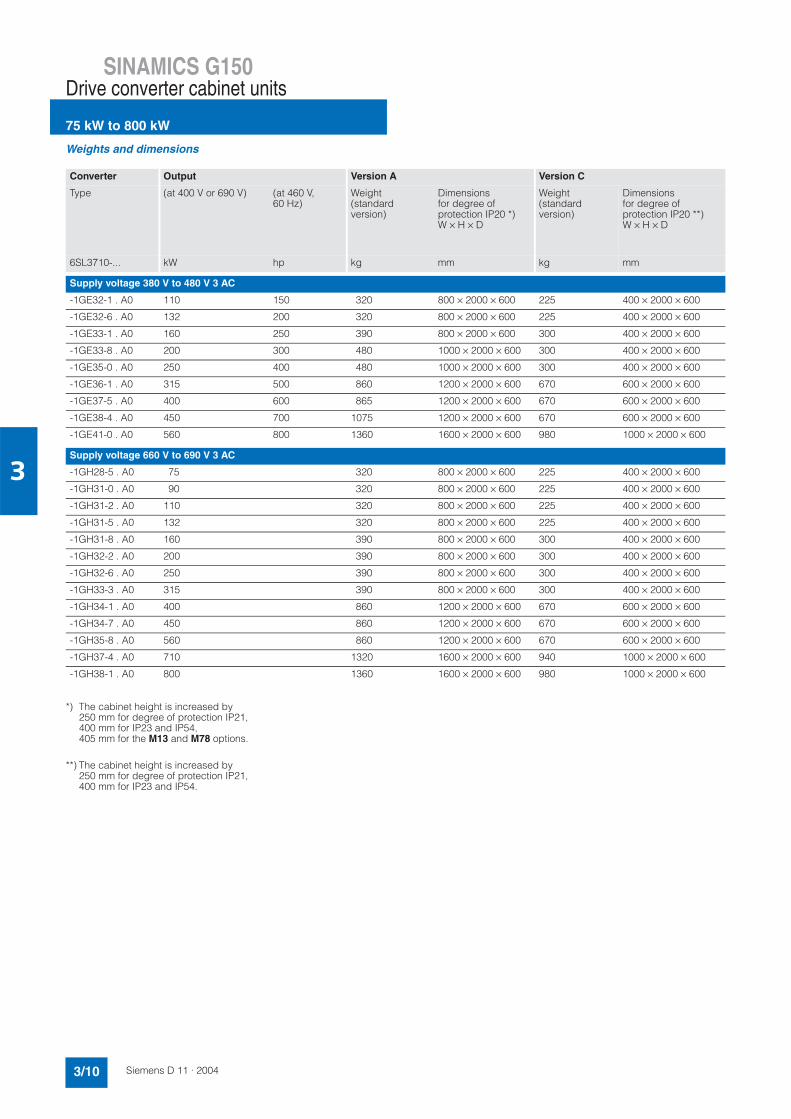
SINAMICS G150Drive converter cabinet units
75 kW to 800 kW
3/10 Siemens D 11 · 2004
3
Weights and dimensions
*) The cabinet height is increased by250 mm for degree of protection IP21,400 mm for IP23 and IP54,405 mm for the M13 and M78 options.
**) The cabinet height is increased by250 mm for degree of protection IP21,400 mm for IP23 and IP54.
Converter Output Version A Version C
Type (at 400 V or 690 V) (at 460 V, 60 Hz)
Weight(standard version)
Dimensionsfor degree of protection IP20 *)W × H × D
Weight(standard version)
Dimensionsfor degree of protection IP20 **)W × H × D
6SL3710-... kW hp kg mm kg mm
Supply voltage 380 V to 480 V 3 AC
-1GE32-1 . A0 110 150 320 800 × 2000 × 600 225 400 × 2000 × 600
-1GE32-6 . A0 132 200 320 800 × 2000 × 600 225 400 × 2000 × 600
-1GE33-1 . A0 160 250 390 800 × 2000 × 600 300 400 × 2000 × 600
-1GE33-8 . A0 200 300 480 1000 × 2000 × 600 300 400 × 2000 × 600
-1GE35-0 . A0 250 400 480 1000 × 2000 × 600 300 400 × 2000 × 600
-1GE36-1 . A0 315 500 860 1200 × 2000 × 600 670 600 × 2000 × 600
-1GE37-5 . A0 400 600 865 1200 × 2000 × 600 670 600 × 2000 × 600
-1GE38-4 . A0 450 700 1075 1200 × 2000 × 600 670 600 × 2000 × 600
-1GE41-0 . A0 560 800 1360 1600 × 2000 × 600 980 1000 × 2000 × 600
Supply voltage 660 V to 690 V 3 AC
-1GH28-5 . A0 75 320 800 × 2000 × 600 225 400 × 2000 × 600
-1GH31-0 . A0 90 320 800 × 2000 × 600 225 400 × 2000 × 600
-1GH31-2 . A0 110 320 800 × 2000 × 600 225 400 × 2000 × 600
-1GH31-5 . A0 132 320 800 × 2000 × 600 225 400 × 2000 × 600
-1GH31-8 . A0 160 390 800 × 2000 × 600 300 400 × 2000 × 600
-1GH32-2 . A0 200 390 800 × 2000 × 600 300 400 × 2000 × 600
-1GH32-6 . A0 250 390 800 × 2000 × 600 300 400 × 2000 × 600
-1GH33-3 . A0 315 390 800 × 2000 × 600 300 400 × 2000 × 600
-1GH34-1 . A0 400 860 1200 × 2000 × 600 670 600 × 2000 × 600
-1GH34-7 . A0 450 860 1200 × 2000 × 600 670 600 × 2000 × 600
-1GH35-8 . A0 560 860 1200 × 2000 × 600 670 600 × 2000 × 600
-1GH37-4 . A0 710 1320 1600 × 2000 × 600 940 1000 × 2000 × 600
-1GH38-1 . A0 800 1360 1600 × 2000 × 600 980 1000 × 2000 × 600

SINAMICS G150Drive converter cabinet units
75 kW to 800 kW
3/11Siemens D 11 · 2004
3
Accessories
1) If the drive converter cabinet units (I < 800 A) are used without the option L26, the user must ensure that relevant precautions to protect the cables and semiconductors are taken on the plant side. The com-bined fuses 3NE1... are recommended for currents up to 800 A.
Output Converter Fusewith existing fuse switch-disconnector (option L26)
Fuse(with semiconductor protection effect) without fuse switch-disconnector 1)
(at 400 V or690 V)
(at460 V, 60 Hz)
Type Order No. Rated current Frames as per DIN 43 620-1
Order No. Rated current Frames as per DIN 43 620-1
kW hp 6SL3710-... A A
Supply voltage 380 V to 480 V 3 AC
110 150 -1GE32-1 . A0 3NA3252 315 2 3NE1230-2 315 1
132 200 -1GE32-6 . A0 3NA3254 355 2 3NE1331-2 350 2
160 250 -1GE33-1 . A0 3NA3365 500 3 3NE1334-2 500 2
200 300 -1GE33-8 . A0 3NA3365 500 3 3NE1334-2 500 2
250 400 -1GE35-0 . A0 3NA3372 630 3 3NE1436-2 630 3
315 500 -1GE36-1 . A0 3NA3475 800 4 3NE1438-2 800 3
400 600 -1GE37-5 . A0 3NA3475 800 4 3NE1448-2 850 3
450 700 -1GE38-4 . A0 Circuit-breaker - - Circuit-breaker - -
560 800 -1GE41-0 . A0 Circuit-breaker - - Circuit-breaker - -
Supply voltage 660 V to 690 V 3 AC
75 -1GH28-5 . A0 3NA3132-6 125 1 3NE1022-2 125 00
90 -1GH31-0 . A0 3NA3132-6 125 1 3NE1022-2 125 00
110 -1GH31-2 . A0 3NA3136-6 160 1 3NE1224-2 160 1
132 -1GH31-5 . A0 3NA3240-6 200 2 3NE1225-2 200 1
160 -1GH31-8 . A0 3NA3244-6 250 2 3NE1227-2 250 1
200 -1GH32-2 . A0 3NA3252-6 315 2 3NE1230-2 315 1
250 -1GH32-6 . A0 3NA3354-6 355 3 3NE1331-2 350 2
315 -1GH33-3 . A0 3NA3365-6 500 3 3NE1334-2 500 2
400 -1GH34-1 . A0 3NA3365-6 500 3 3NE1334-2 500 2
450 -1GH34-7 . A0 3NA3352-6 2x315 3 3NE1435-2 560 3
560 -1GH35-8 . A0 3NA3354-6 2x355 3 3NE1447-2 670 3
710 -1GH37-4 . A0 3NA3365-6 2x500 3 3NE1448-2 850 3
800 -1GH38-1 . A0 Circuit-breaker - - Circuit-breaker - -
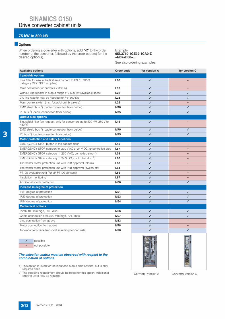
SINAMICS G150Drive converter cabinet units
75 kW to 800 kW
3/12 Siemens D 11 · 2004
3
Options
When ordering a converter with options, add "-Z" to the order number of the converter, followed by the order code(s) for the desired option(s).
Example:6SL3710-1GE32-1CA0-Z+M07+D60+...
See also ordering examples.
The selection matrix must be observed with respect to the combination of options
1) This option is listed for the input and output side options, but is only required once.
2) The stopping requirement should be noted for this option. Additional braking units may be required.
Available options Order code for version A for version C
Input-side options
Line filter for use in the first environment to EN 61 800-3 category C2 (TN/TT supplies)
L00 –
Main contactor (for currents < 800 A) L13 –
Without line reactor in output range P < 500 kW (available soon) L22
2% line reactor may be needed for P > 500 kW L23
Main control switch (incl. fuses/circuit-breakers) L26 –
EMC shield bus 1) (cable connection from below) M70
PE bus 1) (cable connection from below) M75
Output-side options
Sinusoidal filter (on request, only for converters up to 200 kW, 380 V to 480 V)
L15 –
EMC shield bus 1) (cable connection from below) M70
PE bus 1) (cable connection from below) M75
Motor protection and safety functions
EMERGENCY STOP button in the cabinet door L45 –
EMERGENCY STOP category 0, 230 V AC or 24 V DC, uncontrolled stop L57 –
EMERGENCY STOP category 1, 230 V AC, controlled stop 2) L59 –
EMERGENCY STOP category 1, 24 V DC, controlled stop 2) L60 –
Thermistor motor protection unit with PTB approval (alarm) L83 –
Thermistor motor protection unit with PTB approval (switch-off) L84 –
PT100 evaluation unit (for six PT100 sensors) L86 –
Insulation monitoring L87 –
Additional shock protection M60
Increase in degree of protection
IP21 degree of protection M21
IP23 degree of protection M23
IP54 degree of protection M54
Mechanical options
Plinth 100 mm high, RAL 7022 M06
Cable connection area 200 mm high, RAL 7035 M07
Line connection from above M13 –
Motor connection from above M78 –
Top-mounted crane transport assembly for cabinets M90
possible
– not possible
Converter version CConverter version A

SINAMICS G150Drive converter cabinet units
75 kW to 800 kW
3/13Siemens D 11 · 2004
3
Options (continued)
The selection matrix must be observed with respect to the combination of options
3) The order code Y.. requires data in plain text.
Available options Order code for version A for version C
Other options
TM31 customer's terminal block extension G61 –
SMC 30 sensor module cabinet-mountedfor detecting the actual motor speed (available soon)
K50 –
Connection for external auxiliary equipment (controlled max. 10 A) L19 –
Cabinet illumination with service socket L50 –
Anti-condensation heating for cabinet L55 –
Braking unit 100 kW L61 –
Braking unit 200 kW L62 –
Special cabinet paint finish3) Y09
Languages
Documentation in English / French D58
Documentation in English / Spanish D60
Documentation in English / Italian D80
Rating plate and operator panel in English / French T58
Rating plate and operator panel in English / Spanish T60
Rating plate and operator panel in English / Italian T80
Options specific to chemical industry
NAMUR terminal block B00 –
Protective separation for 24 V supply (PELV) B02 –
Separate output for external auxiliaries (uncontrolled) B03 –
Converter acceptance inspections in presence of customer
Visual inspection F03
Function test of the converter without motor connected F71
Function test of the converter with test bay motor (no load) F75
Converter insulation test F77
Customer-specific converter acceptance inspections (on request) F97
possible
– not possible
Converter version CConverter version A

SINAMICS G150Drive converter cabinet units
75 kW to 800 kW
3/14 Siemens D 11 · 2004
3
Options (continued)
Option selection matrix
Certain options are mutually excluding
Electrical options
1) For converters < 500 kW/700 hp, the line reactor (order code L23) is supplied with the converter.For converters > 500 kW/700 hp, the L23 option should also be ordered if• the converters are to be operated with supplies with a high short-cir-
cuit capacity (RSC > 20) (see Engineering information) or• if a line filter is used (option L00).
2) Combination L13/L26 is only possible for currents < 800 A.From 800 A upwards, circuit-breakers are used. These perform the same function as options L13 and L26.
3) Either option L13 is required or, for currents > 800 A, option L26 (cir-cuit-breaker) is required. Braking units may also be needed, depend-ing on the drive stopping time required.
possible combinations
– not possible
L00 L13 L15 L19 L22 L23 L26 L45 L50 L55 L57 L59 L60 L61 L62 L83 L84 L86 L87
L00 – 1) –
L13 2) 3) 3) 3)
L15
L19
L22 – –
L23 1) –
L26 2) 3) 3) 3)
L45
L50
L55
L57 3) 3) – –
L59 3) 3) – –
L60 3) 3) – –
L61 –
L62 –
L83
L84
L86
L87 –

SINAMICS G150Drive converter cabinet units
75 kW to 800 kW
3/15Siemens D 11 · 2004
3
Options (continued)
Mechanical options/electrical options
4) Option L00 includes option M70.5) If the line connection (option M13) and the motor connection (option
M78) are from above, the EMC shield bus and the PE bus are not required in the lower cabinet area.
6) Can only be selected for converters in the voltage range 400 V to 250 kW and 690 V to 315 kW. The M60 option is supplied as standard for larger outputs.
Rating plate data
Ordering examples
Example 1
Task:A drive converter cabinet unit is needed to control the fan speed for a 380 kW fan drive for connecting to an existing 400 V MCC outgoing circuit. The rated speed of the fan is 975 rpm. As a re-sult of the ambient conditions, the converter should be mounted on a 100 mm cabinet plinth and the degree of protection should be IP54. The installation altitude is < 1000 m above sea level and the ambient temperature is 45 °C.
Solution:Due to the existing MCC outgoing circuit, the line connection components, such as main switch, main contactor and line fuses, can be omitted and the space-saving version C can be selected. For this constellation, taking into account the derating factors for IP54 degree of protection and for the increased am-bient temperature, select a drive converter cabinet unit 450 kW, 400 V with the optionsM06 (100 mm cabinet plinth) and M54 (IP54 degree of protection).
The Order No. is:6SL3710-1GE38-4CA0-Z+M06 +M54
Example 2
Task: A 280 kW pump to control the pressure equalization is to be sup-plied via a converter for a brand new district heating pumping station. A 690 V supply is available. The installation altitude is 350 m above sea level and the ambient temperature is 40 °C. The rated speed of the pump is 740 rpm. The pump unit and mo-tor are located in an unmanned substation, so the winding tem-perature of the motor is to be monitored by PT100 resistance thermometers and evaluated by the converter. The color of the drive converter cabinet units is to be RAL 3002.
Solution:Select a drive converter cabinet unit 315 kW, 690 V, version A with the following options:L26 (main switch including fuses),L13 (main contactor),L86 (PT100 evaluation unit) and Y09 (special cabinet paint finish).
The Order No. is:6SL3710-1GH33-3AA0-Z+L26 +L13 +L86 +Y09Cabinet color RAL 3002
L00 M06 M07 M13 M21 M23 M54 M60 M70 M75 M78 M90
L00 4) –
M06 –
M07 –
M13 – – 5) 5)
M21 – – – 6) –
M23 – – –
M54 – – –
M60 – 6) – – –
M70 4) 5) 5)
M75 5) 5)
M78 – – – 5) 5)
M90
T58 T60 T80
T58 – –
T60 – –
T80 – –
possible combinations
– not possible
SINAMICS G150Drive converter cabinet units
75 kW to 800 kW
3/16 Siemens D 11 · 2004
3
Options (continued)
Description of options
B00, B02, B03Options according to NAMUR requirements
Exclusion list to other options:
The following limitations and exclusions resulting together with the NAMUR terminal block B00 must be observed with regard to the other available options.
With options such as L50, L55, L86, the connection is as de-scribed in the standard. There is no wiring to the NAMUR termi-nal block.
B00 NAMUR terminal block
The terminal block is designed according to the requirements and directives of the standards association for measurement and control in the chemical industry (NAMUR recommendation NE37), i.e. fixed terminals are assigned to certain functions of the devices. The inputs and outputs connected to the terminals comply with the requirements "Protective extra-low voltage PELV".
The terminal block and the associated functions are reduced to a required amount. In comparison to the NAMUR recommenda-tion, optional terminals are not listed.
The 24 V supply is made at the customer end via the terminals -A1-X2:1-3 (fused inside converter with 1 A). It must be ensured that the safety requirements "Protective extra-low voltage PELV" are complied with.
For temperature monitoring of explosion-proof motors, the B00option contains a PTC thermistor with PTB approval. A switch-off is carried out if the limit is exceeded. The associated PTC sensor is connected to terminal -A1-X3:90, 91.
B02 Protective separation for 24 V supply (PELV)
If no protective separation for 24 V supply (PELV) is available at the customer end, this option is used to fit a second power sup-ply to guarantee the PELV. (Terminal assignments as for B00 op-tion, 24 V supply at terminals -A1-X1:1, 2, 3 omitted)
Attention: The B02 option is only possible together with B00.
B03 Separate output for external auxiliaries (uncontrolled)
If a motor fan is to be powered on the plant side, the B03 optionprovides an uncontrolled external output fused with 10 A. As soon as the supply voltage is present at the converter input, a voltage is also present at these terminals. This corresponds to the converter input voltage (V = VPS). This should be observed when planning the external fans.
Attention: The B03 option is only possible together with B00.
Not per-missible withoption
Reason
L45, L57, L59, L60
An EMERGENCY STOP of category 0 is already included in the NAMUR version. Access to the forced power supply disconnection is at the terminals -A1-X2: 17, 18.
L83, L84 The B00 option already provides a PTC thermistor evalua-tion unit as standard (shutdown).
L19 Option B03 could be selected as an alternative.This will provide a reduced scope for external auxiliary equipment.
L87 The insulation monitor monitors the complete network which is electrically connected together. An insulation monitor must therefore be provided on the plant side.
Terminal -A1-X2:
Meaning Preassignment Comment
10 DI ON (dynamic) / ON/OFF (static)
The effective mode can be coded using a wire jumper on the terminal -A1-400:9; 10.
11 DI OFF (dynamic)
12 DI Faster
13 DI Slower
14 DI RESET
15 DI Interlocking
16 DI Counterclockwise "0" signal for CW phase sequence "1" signal for CCW phase sequence
17, 18 PS disconnection EMERGENCY STOP sequence
30, 31 Ready to run Relay output (NO contact)
32, 33 Motor rotates Relay output (NO contact)
34 DO (NO) Fault Relay output (changeovercontact)35 DO (COM)
36 DO (NC)
50, 51 AI0/4-20 mA
Speed setpoint
60, 61 AO0/4-20 mA
Motor frequency
62, 63 AO0/4-20 mA
Motor current Motor current is default setting; can be reparameterized for other variables
Terminal -A1-X2:
Meaning
1 M Reference conductor
2 P24 Incoming supply 24 V DC
3 P24 Outgoing circuit 24 V DC
Terminal -A1-X3:
Meaning
90, 91 AI Connection of PTC sensor
Terminal -A1-X1:
Meaning
1, 2, 3, PE Output for motor of external fan
Terminal -A1-X2:
Meaning Preassignment Comment

SINAMICS G150Drive converter cabinet units
75 kW to 800 kW
3/17Siemens D 11 · 2004
3
Options (continued)
F03, F71, F75, F77, F97Converter acceptance inspections in presence of the customer
Order code
Description
F03 Visual inspection
The scope of the acceptance inspection comprises:• Checking the degree of protection• Checking the equipment (components)• Checking the equipment identifier• Checking the clearance and creepage dis-
tances• Checking the cables• Checking the customer documentation• Submitting the acceptance reportThe checks are carried out with the converter deenergized.
F71 Functionaltest of the converter withoutmotor con-nected
The scope of the acceptance inspection comprises:• Visual inspection as described for option
F03• Check of power supply• Check of protective and monitoring devices
(simulation)• Check of fans• Precharging test• Functional test without connected motor • Submitting the acceptance reportAfter the visual inspection with the converter switched off, the converter is connected to rated voltage. No current flows at the con-verter's output.
F75 Functionaltest of the converter with test- bay motor (no load)
The scope of the acceptance inspection comprises:• Visual inspection as described for option
F03• Check of power supply• Check of protective and monitoring devices
(simulation)• Check of fans• Precharging test• Functional test with test-bay motor (no load)• Submitting the acceptance reportAfter the visual inspection with the converter switched off, the converter is connected to the rated voltage. A low-level current flows at the converter's output in order to operate the the test-bay motor (no load).
F77 Insulationtest of converter
The scope of the acceptance inspection comprises:• High-voltage test• Measurement of insulation resistance
F97 Customer-specificconverter accep-tanceinspec-tions (on request)
If acceptances are desired which are not covered by the options F03, F71, F75 or F77,customer-specific converter acceptance inspections/supplementary tests can be ordered using the Order code F97 onrequest and following technical clarification.
SINAMICS G150Drive converter cabinet units
75 kW to 800 kW
3/18 Siemens D 11 · 2004
3
Options (continued)
G61TM31 Customer’s terminal block extension
In the standard version, the SINAMICS G150 cabinet units al-ready include an interface module (TM31 terminal module). With a second module, the number of available digital inputs/outputs and the number of analog inputs/outputs within the drive system can be expanded.
K50SMC30 sensor module cabinet-mounted for detecting the actual motor speed (available soon)
The SMC30 encoder module can be used to record the actual motor speed. The signals from the rotary pulse encoder are con-verted here and made available for evaluation via the DRIVE-CLiQ interface of the controller.
The following encoders are supported by the SMC30:• TTL encoders• HTL encoders
L00 Line filter for use in the first environment, category C2 (TN/TT supplies)
To limit the emitted interference, the drive converters are equipped as standard with a radio interference suppression fil-ter that conforms to the limits defined in Category C3. Optional filters are available for use in the first environment (Category C2).
The drive converters conform to the noise immunity require-ments defined in EN 61 800-3 for the second environment, and thus also with the lower noise immunity requirements in the first environment.
In conjunction with the line reactor, the line filters reduce the ra-dio interference voltage that occurs at the converter. Option L23should be ordered in addition for converter outputs > 500 kW.
To allow the power cable shield to be connected in conformance with EMC requirements, an additional EMC shield bus (M70 op-tion) is factory fitted at the converter input and output. A sepa-rate order is not required in this case.
L13 Main contactor (for currents < 800 A)
The SINAMICS G150 drive converter cabinet units are designed as standard without a line contactor. Option L13 is needed if a switching element is required for disconnecting the cabinet from the supply (needed for EMERGENCY STOP). The contactor is energized and powered inside the converter.
L15Sinusoidal filter
Sinusoidal filters are available in the voltage range from 380 V to 480 V for a converter output up to 200 kW.
The sinusoidal filter at the converter output delivers practically sinusoidal voltages on the motor so that standard motors can be used without special cables and without any power reduction. Standard cables can be used. The maximum permitted motor in-coming cable length is 300 m.
Note: The pulse frequency of the converter must be increased when used in conjunction with the L15 option. This reduces the power available at the converter output (derating factor 0.88). The control factor for the output voltage drops to around 90%. It should be noted that the reduced voltage at the motor terminals compared to the rated motor voltage means that the motor switches to field weakening mode earlier.
L19 Connection for external auxiliary equipment
An outgoing circuit fused at max. 10 A for external auxiliary equipment (for example, separately driven motor fan).
The voltage is tapped at the converter input and, therefore, has the same level as the supply voltage.
The outgoing circuit can be controlled internally by the converter or externally.
L22 Without line reactor
If the converter is powered via a separate transformer, or if the ratio between the line short-circuit power at the point of connec-tion and the converter's rated output is low, the line reactor sup-plied as standard may be omitted for converters < 500 kW (see Engineering information). This line reactor will be needed, how-ever, if a line filter is used (L00 option).
L23 Line reactor uK = 2%
Converters up to 500 kW contain the line reactor as standard. For converter outputs > 500 kW, the line reactor (uK = 2%) is available as an option since, in this output range, the converters are often connected to a medium-voltage supply system via transformers that are matched to the converter output.
Terminal-X50:
Meaning
4 Checkback contact (NO contact) Contactor closed
5 Checkback contact (NC contact) Contactor closed
6 Root
Terminal -X155:
Meaning Range
1 L1 AC 380 V to 690 V
2 L2 AC 380 V to 690 V
3 L3 AC 380 V to 690 V
11 Contactor control AC 230 V
12 Contactor control AC 230 V
13 Circuit-breaker checkback AC 230 V/0.5 A;DC 24 V/2 A
14 Circuit-breaker checkback AC 230 V/0.5 A;DC 24 V/2 A
15 Contactor checkback AC 230 V/6 A
16 Contactor checkback AC 230 V/6 A
PE PE

SINAMICS G150Drive converter cabinet units
75 kW to 800 kW
3/19Siemens D 11 · 2004
3
Options (continued)
L26 Main control switch (incl. fuses or circuit-breakers)
Up to 800 A, a switch-disconnector with externally mounted fuses is offered as the main control switch. At currents above 800 A a circuit-breaker is fitted rather than a switch-disconnec-tor. The circuit-breaker is energized and supplied within the con-verter.
L45 EMERGENCY STOP button in the cabinet door
The EMERGENCY STOP button with protective collar is fitted in the converter cabinet door and its contacts are connected to the terminal block. The EMERGENCY STOP functions of category 0 or 1 can be activated in conjunction with options L57, L59 and L60.
*) Used inside the converter with options L57 to L60
L50 Cabinet illumination with service socket
One universal lamp with an integrated service socket is installed for each cabinet element.
The power supply (on terminal board -X390) for the cabinet illu-mination and socket must be provided externally and fused at max. 10 A. The cabinet illumination is switched on manually via a switch or automatically by an integrated motion detector. The mode is switch-selected.
L55 Anti-condensation heating for cabinet
The anti-condensation heating is recommended at low ambient temperatures and high levels of humidity to prevent condensa-tion. One 100 W heater is fitted for each cabinet panel (two heat-ers are fitted for each panel in the case of cabinet panel widths from 800 mm to 1200 mm).
The power supply to the heater (110 V to 230 V AC, on terminal board -X240) must be provided externally and fused at max. 16 A.
L57 EMERGENCY STOP category 0 (230 V AC or 24 V DC)
EMERGENCY STOP category 0 for uncontrolled stop to EN 60 204.
The function includes voltage disconnection of the converter via the line contactor with bypassing of the microprocessor control-ler by means of a safety combination according to EN 60 204-1. The motor coasts in the process. When delivered, the button cir-cuit is preset to 230 V AC. Jumpers must be set when using 24 V DC.
Attention: The L57 option always assumes that the converter can be electrically isolated from the supply; i.e. the L13 option for converter currents ≤ 800 A and the L26 option for converter cur-rents > 800 A.
L59 EMERGENCY STOP category 1 (230 V AC)
EMERGENCY STOP category 1 for controlled stop to EN 60 204.
The function includes rapid shutdown of the drive via fast stop using a ramp-down ramp to be parameterized by the user. This is followed by voltage disconnection as described for the EMERGENCY STOP category 0.
A braking unit may be necessary to achieve the required shut-down times.
Attention: The L59 option always assumes that the converter can be electrically isolated from the supply; i.e. the L13 option for converter currents ≤ 800 A and the L26 option for converter cur-rents > 800 A.
Terminal-X50:
Meaning
1 Checkback contact (NO contact)Main control switch/circuit-breaker closed
2 Checkback contact (NC contact)Main control switch/circuit-breaker closed
3 Root
Terminal -X120:
Meaning
1 Checkback contact of EMERGENCY STOP button in cabinet door
2 Checkback contact of EMERGENCY STOP button in cabinet door
3 Checkback contact of EMERGENCY STOP button in cabinet door *)
4 Checkback contact of EMERGENCY STOP button in cabinet door *)
Terminal-X390:
Meaning
1 L1 (230 V AC)
2 N
3 PE
Terminal-X240:
Meaning
1 L1 (110 V to 230 V AC)
2 N
3 PE
Terminal -X120:
Meaning
7 Looping in EMERGENCY STOP button from system side; remove jumper 7-8!
8 Looping in EMERGENCY STOP button from system side; remove jumper 7-8!
15 "On" for monitored start; remove jumper 15-16!
16 "On" for monitored start; remove jumper 15-16!
17 Checkback "Triggering safety combination"
18 Checkback "Triggering safety combination"
Terminal -X120:
Meaning
7 Looping in EMERGENCY STOP button from system side; remove jumper 7–8!
8 Looping in EMERGENCY STOP button from system side; remove jumper 7–8!
15 "On" for manual start; remove jumper 15-16!
16 "On" for manual start; remove jumper 15-16!
17 Checkback "Triggering safety combination"
18 Checkback "Triggering safety combination"

SINAMICS G150Drive converter cabinet units
75 kW to 800 kW
3/20 Siemens D 11 · 2004
3
Options (continued)
L60 EMERGENCY STOP category 1 (24 V DC)
EMERGENCY STOP category 1 for controlled stop to EN 60 204.
The function includes rapid shutdown of the drive via fast stop using a ramp-down ramp to be parameterized by the user. This is followed by voltage disconnection as described for the EMER-GENCY STOP category 0.
A braking unit may be necessary to achieve the required shut-down times.
Attention:The L60 option always assumes that the converter can be electrically insulated from the supply; i.e. the L13 option for converter currents ≤ 800 A and the L26 option for converter cur-rents > 800 A.
L61, L62 Braking units
It may be necessary to use braking units for drives that allow re-generative braking.
The braking unit comprises two components: a braking module fitted in the converter cabinet, and a braking resistor which must be provided externally (IP20 degree of protection). The braking unit functions as an autonomous unit, and does not require an external power supply. During the braking process, the kinetic energy is converted into heat in the external braking resistor. A max. cable length of 50 m is permissible between the braking module and the braking resistor. It is therefore possible to re-lease the heat outside the converter room.
The braking resistor is connected to terminal block -X5 on the drive converter cabinet unit:
P 20: Permitted output for a period of 20 s, cycle time 90 s
If greater braking powers are required in addition to the braking units listed here, then braking units may be connected in parallel for greater converter outputs. In this case, a braking module is assigned to each braking resistor. Braking units may be con-nected in parallel upon request.
L83 Thermistor motor protection unit (alarm)
Thermistor motor protection unit (with PTB approval) for PTC thermistor sensors (type A) for alarm. The power supply for the thermistor motor protection unit and the evaluation is provided within the converter.
L84 Thermistor motor protection unit (switch-off)
Thermistor motor protection unit (with PTB approval) for PTC thermistor (type A) for switch-off. The power supply for the ther-mistor motor protection unit and the evaluation is provided within the converter.
L86 PT100 evaluation unit
The PT100 evaluation unit can monitor up to 6 sensors. The sen-sors can be connected using a 2-wire or 3-wire system. The limit values can be programmed by the user for each channel.
In the factory setting, the measuring channels are divided into two groups of three channels. With motors, for example, three PT100 can, therefore, be monitored in the stator windings and two PT100 in the motor bearings. Channels that are not used can be suppressed using appropriate parameter settings.
The output relays are integrated into the internal fault and switch-off sequence of the converter. The signals can also be picked up by the customer via two spare fault signaling relays. Two user-programmable analog outputs are also available (0/4 to 20 mA or 0/2 to 10 V) for integration in a higher-level controller.
Terminal -X120:
Meaning
7 Looping in EMERGENCY STOP button from system side; remove jumper 7–8!
8 Looping in EMERGENCY STOP button from system side; remove jumper 7–8!
15 "On" for manual start; remove jumper 15-16!
16 "On" for manual start; remove jumper 15-16!
17 Checkback "Triggering safety combination"
18 Checkback "Triggering safety combination"
Terminal-X5:
Meaning
1 Connection of braking resistor
2 Connection of braking resistor
Option BrakingpowerP20
Drive converter cabinet units 380 V to 480 V
Drive converter cabinet units 660 V to 690 V
L61 100 kW 110 kW to 132 kW 75 kW to 132 kW
L62 200 kW 160 kW to 560 kW 160 kW to 800 kW
Terminal-F127:
Meaning
T1 Connection of sensor loop
T2 Connection of sensor loop
Terminal-F125:
Meaning
T1 Connection of sensor loop
T2 Connection of sensor loop
Terminal -A1-A140:
Meaning
T11 to T13 PT100; sensor 1; group 1
T21 to T23 PT100; sensor 2; group 1
T31 to T33 PT100; sensor 3; group 1
T41 to T43 PT100; sensor 1; group 2
T51 to T53 PT100; sensor 2; group 2
T61 to T63 PT100; sensor 3; group 2
The sensors can be connected to the PT100 evaluation unit using using a two-wire or three-wire system.In a two-wire system, inputs Tx1 and Tx3 must be used.In a three-wire system, input Tx2 must also be connected (x = 1, 2, ..., 6)
51, 52, 54 Relay outputLimit for group 1 reached; (changeover contact)
61, 62, 64 Relay outputLimit for group 2 reached; (changeover contact)
Ground (OUT1)
Analog output OUT1; sensor group 1
U1 (OUT1) Analog output OUT1; sensor group 1
I1 (OUT1) Analog output OUT1; sensor group 1
Ground (OUT2)
Analog output OUT2; sensor group 2
U2 (OUT2) Analog output OUT2; sensor group 2
I2 (OUT2) Analog output OUT2; sensor group 2

SINAMICS G150Drive converter cabinet units
75 kW to 800 kW
3/21Siemens D 11 · 2004
3
Options (continued)
L87 Insulation monitoring
An insulation monitor must be used if the converter is operated on an isolated-neutral system. This device monitors the com-plete electrically connected circuit for insulation faults.
An alarm is output in the event of a fault.
Attention: Only one insulation monitor can be used in an electri-cally connected network.
The response concept in the event of an earth fault in the iso-lated-neutral system can vary, so output relays are available for linking to a system-side control. It is also possible to integrate the outputs into the converter monitoring on the plant side.
M06 Plinth 100 mm high, RAL 7022
The additional cabinet plinth allows larger bending radii for ca-bles (cable inlet from below) and the routing of them within the plinth.
The cabinet plinth is always colored RAL 7022. A special color is not possible. It is delivered completely fitted with the cabinet. The height of the operator panel changes accordingly.
M07 Cable connection area 200 mm high, RAL 7035
The cable connection area is made of stable sheet steel and in-creases the flexibility for the cable connection (inlet from below) and allows routing of cables within the connection area. It is de-livered completely fitted with the cabinet. The height of the oper-ator panel changes accordingly.
Attention: The cable connection area is colored RAL 7035 as standard. If a special color is requested for the cabinet (Order code Y09), the cable connection area is also painted in this color.
M13Line connection from above
The control cabinet is provided with an additional hood in the case of a power supply from above. The connection straps for the power cables, the clamping bar for mechanically securing the cables, an EMC shield bus and a PE busbar are located within the hood.
The cabinet height is then increased by 405 mm. The busbars for the connection from above are delivered completely fitted. For transport reasons, the hoods are delivered separately and must be fitted on site. Crane transport assemblies (option M90)can still be used. However, these must be removed on site in or-der to fit the hoods. Use of rope spreaders should be considered in the case of small crane hook heights.
A non-drilled mounting plate made of aluminium (5 mm thick) should be provided on the top of the hood for feeding in the ca-bles. Depending on the number of cables and the cable cross-sections used, holes must be provided in this mounting plate for attaching cable glands for feeding in the cables on the plant side.
Note: The control cables are still connected from below. With the M13 option, the standard line connection from below is not used.
The hoods have IP21 degree of protection. Additional plastic ventilation grilles and filter pads are provided in combination with the M23 and M54 options.
Attention: The hoods are colored RAL 7035 as standard. If a special color is requested for the cabinet (order code Y09), the hoods are also painted in this color. Ventilation grilles used with IP23 and IP54 degrees of protection are colored RAL 7035 and cannot be painted.
The covers used with the M60 option are included in the scope of delivery.
M21 Degree of protection IP21
Cabinet version in IP20, but with additional top cover or canopy. The cabinet height is then increased by 250 mm.
For transport reasons, the top covers or canopies are delivered separately and must be fitted on site.
Attention: The top covers or canopies are colored RAL 7035 as standard. If a special color is requested for the cabinet (Order code Y09), the top covers or canopies are also painted in this color.
M23 Degree of protection IP23
Drive converter cabinet units with IP23 degree of protection are supplied with additional hoods and plastic ventilation grilles in the air inlet and outlet. The cabinet height is then increased by 400 mm. The covers used with the M60 option are included in the scope of delivery.
For transport reasons, the hoods are delivered separately and must be fitted on site.
Attention: The hoods are colored RAL 7035 as standard. If a special color is requested for the cabinet (order code Y09), the hoods are also painted in this color. The molded plastic parts e.g. ventilation grilles) are colored RAL 7035 and cannot be painted.
Terminal -A1-A101:
Meaning
11 Alarm relay ALARM 1
12 Alarm relay ALARM 1
14 Alarm relay ALARM 1
21 Alarm relay ALARM 2
22 Alarm relay ALARM 2
24 Alarm relay ALARM 2
M+ External kΩ display 0 µA to 400 µA
M- External kΩ display 0 µA to 400 µA
R1 External reset key (NC contact or wire jumper otherwise the fault code is not stored)
R2 External reset key (NC contact or wire jumper)
T1 External test button
T2 External test button

SINAMICS G150Drive converter cabinet units
75 kW to 800 kW
3/22 Siemens D 11 · 2004
3
Options (continued)
M54 IP54 degree of protection
Drive converter cabinet units with degree of protection IP54 are supplied with additional hoods, plastic ventilation grilles, and a filter medium in the air inlet and outlet. The cabinet height is then increased by 400 mm. The covers used with the M60 option are included in the scope of delivery. Maintenance of the filters must be carried out according to the local ambient conditions.
For transport reasons, the hoods are delivered separately and must be fitted on site.
Attention: With IP54 degree of protection, the derating factors for the output current must be observed.
Attention: The hoods are colored RAL 7035 as standard. If a special color is requested for the cabinet (order code Y09), the hoods are also painted in this color. The molded plastic parts e.g. ventilation grilles) are colored RAL 7035 and cannot be painted.
M60 Additional shock protection
The drive converter cabinet units are designed as standard ac-cording to BGV A2. The M60 option provides additional covers (outside normal arm's reach) in the vicinity of the AC rails and above the power section (can only be selected as an option with converters up to 250 kW in the 400 V range and with converters up to 315 kW in the 690 V range, with degrees of protection IP20 and IP21; otherwise supplied as standard).
M70 EMC shield bus (cable connection from below)
The EMC shield bus is used to connect shielded power cables for power supply and motor infeed. The EMC shield bus is sup-plied as standard with the L00 option (line filter).
M75 PE busbar (cable connection from below)
The PE busbar is used to run the PE conductor for the supply and motor infeed cables.
This can be ordered as an option for converters with low output and currents I < 700 A. The PE busbar is supplied as standard for output currents I > 700 A or groups of cabinets consisting of several cabinet panels.
M78Motor connection from above
The control cabinet is provided with an additional hood for a mo-tor connection from above. The connection straps for the power cables, the clamping bar for mechanically securing the cables, an EMC shield bus, and a PE busbar are located within the hood.
The cabinet height is then increased by 405 mm. The busbars for the connection from above are delivered completely fitted. For transport reasons, the hoods are delivered separately and must be fitted on site. Crane transport assemblies (option M90)can still be used. However, these must be removed on site in or-der to fit the hoods. Use of rope spreaders should be considered in the case of small crane hook heights.
A non-drilled mounting plate made of aluminum (5 mm thick) should be provided on the top of the hood for feeding in the ca-bles. Depending on the number of cables and the cable cross-sections used, holes must be provided in this mounting plate for attaching cable glands for feeding in the cables on the plant side.
Note: The control cables are still connected from below. With the M78 option, the standard motor connection from below is not used.
The hoods have IP21 degree of protection. Additional plastic ventilation grilles and filter pads are provided in combination with the M23 and M54 options.
Attention: The hoods are colored RAL 7035 as standard. If a special color is requested for the cabinet (order code Y09), the hoods are also painted in this color. Ventilation grilles used with IP23 and IP54 degrees of protection are colored RAL 7035 and cannot be painted.
The covers used with the M60 option are included in the scope of delivery.
M90 Top-mounted crane transport assembly for cabinets
In the case of single cabinets up to a width of 600 mm, the crane transport assembly has transport eye bolts. With a cabinet width of 800 mm or more, transport rails are used.
Y09 Special cabinet paint finish
The drive converter cabinet units are colored RAL 7035 as stan-dard. The special color must be specified in plain text when or-dering. All RAL colors can be selected which are available as powdered coatings. If options such as cable connection area (Order code M07), top covers or canopies (Order code M21),hoods (Order codes M23/M54) or cable connection from above (Order codes M13/M78) are required for the drive converter cab-inet units, these are provided in the ordered cabinet color. The molded plastic parts e.g. ventilation grilles) are colored RAL 7035 and cannot be painted.

Siemens D 11 · 2004
4/2 Selection guides4/2 SIZER configuration tool4/3 STARTER drive/commissioning
software4/4 Drive ES engineering system
4/5 Configuring the SINAMICS G130 converter chassis units
4/5 Dimensioning and selection infor-mation
4/8 Customer's terminal blocks4/14 Line-side components4/15 Components in the DC link
4/17 Configuring the SINAMICS G150 drive converter cabinet units
4/17 Dimensioning and selection infor-mation
4/18 Customer's terminal block4/19 Conductor cross-sections and
terminals4/21 Line-side components4/22 Components in the DC link
4/24 Dimensioning drives
4/25 Motors
Engineering information

Engineering informationSelection guides
SIZER configuration tool
4/2 Siemens D 11 · 2004
4
Overview
The SIZER PC tool provides an easy-to-use means of configur-ing the SINAMICS and MICROMASTER 4 drive family. It pro-vides technical support when sizing the hardware and firmware components required for a drive task. SIZER supports the com-plete configuration of the drive system, from simple individual drives to complex multi-axis applications.
SIZER supports all stages of the configuration in the form of a workflow, which comprises the following stages:• Selection of the line supply• Dimensioning of the motor(s)• Calculation of the drive components• Selecting the required accessories• Selection of the line-side and motor-side power options.
When SIZER was being developed, particular importance was placed on high usability and a universal, function-based ap-proach to the drive task. The extensive user guidance makes us-ing the tool easy. Status information keeps you continually in-formed of the progress of the configuration process.
The SIZER user interface is available in German and English.
The drive configuration is saved in a project. In the project, the components and functions used are displayed in a hierarchical tree structure.
The project view supports:• The configuration of a number of drive devices• The copying/pasting/editing of existing drives that have al-
ready been configured.
The configuration process produces the following results:• A parts list of the components required• Technical data• Characteristics• Location diagram and dimension drawings
These results are displayed in a results tree and can be printed out for documentation purposes.
User support is provided by the technological online help menu, which provides the following information:• Detailed technical data• Information about the drives and their components• Decision-making criteria for the selection of components
Minimum hardware and software requirements
PG or PC with Pentium™ II 400 MHz (Windows™ NT/2000),Pentium™ III 500 MHz (Windows™ XP)
256 MB RAM
At least 600 MB of free hard disk space
An additional 100 MB of free hard disk space on Windows sys-tem drive
Monitor resolution 1024×768 pixels
Windows™ NT 4.0 SP5, 2000 SP2, XP Professional SP1
Microsoft Internet Explorer 5.5 SP2
Selection and ordering data
Order No.
SINAMICS MICROMASTER SIZER configuration toolGerman/English
6SL3070-0AA00-0AG0
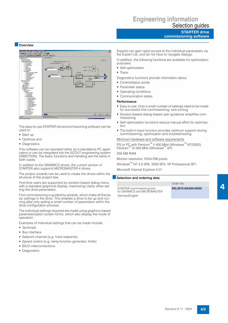
Engineering informationSelection guides
STARTER drivecommissioning software
4/3Siemens D 11 · 2004
4
Overview
The easy-to-use STARTER drive/commissioning software can be used to:• Start up• Optimize and• Diagnostics.
This software can be operated either as a standalone PC appli-cation or can be integrated into the SCOUT engineering system (SIMOTION). The basic functions and handling are the same in both cases.
In addition to the SINAMICS drives, the current version of STARTER also supports MICROMASTER 4 drives.
The project wizards can be used to create the drives within the structure of the project tree.
First-time users are supported by solution-based dialog menu, with a standard graphical display, maximizing clarity when set-ting the drive parameters.
First commissioning is guided by wizards, which make all the ba-sic settings in the drive. This enables a drive to be up and run-ning after only setting a small number of parameters within the drive configuration process.
The individual settings required are made using graphics-based parameterization screen forms, which also display the mode of operation.
Examples of individual settings that can be made include:• Terminals• Bus interface• Setpoint channel (e.g. fixed setpoints)• Speed control (e.g. ramp-function generator, limits)• BICO interconnections• Diagnostics
Experts can gain rapid access to the individual parameters via the Expert List, and do not have to navigate dialogs.
In addition, the following functions are available for optimization purposes:• Self-optimization• Trace
Diagnostics functions provide information about:• Control/status words• Parameter status• Operating conditions• Communication states
Performance• Easy to use: Only a small number of settings need to be made
for successful first commissioning: axis turning• Solution-based dialog-based user guidance simplifies com-
missioning• Self-optimization functions reduce manual effort for optimiza-
tion• The built-in trace function provides optimum support during
commissioning, optimization and troubleshooting.
Minimum hardware and software requirements
PG or PC with Pentium™ II 400 MHz (Windows™ NT/2000),Pentium™ III 500 MHz (Windows™ XP)
256 MB RAM
Monitor resolution 1024×768 pixels
Windows™ NT 4.0 SP6, 2000 SP3, XP Professional SP1
Microsoft Internet Explorer 5.01
Selection and ordering data
Order No.
STARTER commissioning tool for SINAMICS and MICROMASTERGerman/English
6SL3072-0AA00-0AG0

Engineering informationSelection guides
Drive ES engineering system
4/4 Siemens D 11 · 2004
4
Overview
Drive ES is the engineering system used to integrate Siemens drive technology into the SIMATIC automation world easily, effi-ciently and cost-effectively in terms of communication, configu-ration and data management. The STEP 7 Manager user inter-face provides the basis for this procedure.
Various software packages are available for SINAMICS G and SINAMICS S:• Drive ES Basic
For first-time users to the world of Totally Integrated Automa-tion and the option for routing beyond network limits and the use of the SIMATIC teleservice.Drive ES Basic is the basic software program for setting the parameters of all drives online and offline.Drive ES Basic enables both the automation system and the drives to be handled via the SIMATIC Manager user interface. Drive ES Basic is the starting point for common data archiving of complete projects and for extending the use of the SIMATIC teleservice to drives. Drive ES Basic provides the configura-tion tools for the new motion control functions of slave-to-slave communication, equidistance and isochronous operation with PROFIBUS DP.
• Drive ES SIMATICSimply parameterize the STEP 7 communication instead of programming.In order to use Drive ES SIMATIC, STEP 7 must be installed. A SIMATIC block library is supplied for simple and reliable pro-gramming of the PROFIBUS interface on the SIMATIC CPU for the drives. There is no separate time-consuming program-ming of the exchange of data between the SIMATIC CPU and the drive.For Drive ES users need to remember is:Copy - Adapt - Download - Ready.Customized, fully-developed function blocks from the li-brary are transferred into a user-specific project.Frequently required functions are set to run in program format: - Read out complete diagnostics buffer automatically from the
drive- Download complete parameter set automatically from the
SIMATIC CPU to the drive, e.g. in the event of a device being replaced
- Load part parameter sets (e.g. in the event of a recipe or product replacement) automatically from the SIMATIC-CPU
- Read back, i.e. update, complete parameterization or part parameter sets from the drive to the SIMATIC-CPU
• Drive ES PCS 7Integrates drives with the PROFIBUS interface into the SIMATIC PCS 7 process control system.Drive ES PCS 7 can only be used with SIMATIC PCS 7 Version 5.0 and later. Drive ES PCS 7 provides a function block library with function blocks for the drives and the corre-sponding faceplates for the operator station, which enables the drives to be operated from the PCS 7 process control sys-tem.
For further information please visit us on the Internet at:
http://www.siemens.com/drivesolutions
Selection and ordering data
!"
!
# #$
%&'& Order No.
Drive ES Basic V 5.3• Configuration software
for integrating drives into Totally Integrated Automation
• Requirement: STEP 7 V 5.1 and higher, SP 3
• Supply format: CD-ROMde, en, fr, es, itwith electronic documentation
Single license 6SW1700-5JA00-3AA0
Multi-user license, 60 x 6SW1700-5JA00-3AA1
Update service for single-user license 6SW1700-0JA00-0AB2
Update service for multi-user license 6SW1700-0JA00-1AB2
Upgrade from V 5.x to V 5.3 6SW1700-5JA00-3AA4
Drive ES SIMATC V 5.3• Function block library for SIMATIC
for the parameterization of communication with the drives
• Requirement: STEP 7 V 5.1 and higher, SP 3
• Supply format: CD-ROMde, en, fr, es, itwith electronic documentation
Single-user license incl. 1 x runtime license
6SW1700-5JC00-3AA0
Runtime license 6SW1700-5JC00-1AC0
Update service for single-user license 6SW1700-0JC00-0AB2
Upgrade from V 5.x to V 5.3 6SW1700-5JC00-3AA4
Drive ES PCS 7 V 6.0• Function block library for PCS 7
for the integration of drives• Requirement: PCS 7 V 6.0 and higher• Supply format: CD-ROM
de, en, fr, es, itwith electronic documentation
Single-user license incl. 1 x runtime license
6SW1700-6JD00-0AA0
Runtime license 6SW1700-5JD00-1AC0
Update service for single-user license 6SW1700-0JD00-0AB2
Upgrade from V 5.x to V 6.x 6SW1700-6JD00-0AA4

Engineering informationConfiguring the SINAMICS G130 drive converter chassis units
Dimensioning and selection information
4/5Siemens D 11 · 2004
4
Overview
SINAMICS G130 drive converter chassis units provide machine builders and plant constructors with a modular drive system that can be tailored to specific applications.
SINAMICS G130 drive converter chassis units consist of two modular, stand-alone components:• Power module and• Control unit
They may be located separately from one another or combined in a single unit. The power module contains a slot for the control unit. On the 315 kW unit of voltage range 660 V - 690 V, this is the left-hand side wall. On all other units, the slot is in the power module.
The power modules are supplied with a DRIVE-CLiQ cable for communication and the cable for the 24 V supply to the control unit. This requires the control unit to be installed in the power module. If the two units are in a separate location, the cables should be ordered in the appropriate lengths.
The CU320 control unit is part of the control unit kit, which also includes a CompactFlash card and the documentation on CD-ROM. This will reduce the ordering required.
Predefined interfaces, via terminal block or PROFIBUS, make commissioning and control of the drive much easier. The inter-faces of the CU320 control unit can be supplemented with addi-tional modules, such as the withdrawable TB30 terminal board of the TM31 terminal module.
If further customer interfaces are needed to communicate with the drive, an external 24 V supply should be provided.
The following flow chart shows how to select the correct con-verter components (see page 4/6).
Rated data and continuous operation of converters for drives with low demands on control performance
SINAMICS G130 drive converter chassis units are designed for applications with low demands on dynamic response and con-trol accuracy, offering no possibility of regenerative feedback.
They are designed for motorized operation at the supply volt-ages specified in the selection tables. These values take ac-count of voltage fluctuations within the defined tolerances.
The currents specified in the selection and ordering data are available across the entire frequency/speed setting range.
As far as the rated currents are concerned, the units are dimen-sioned for continuous operation with the specified rated output currents. The values are based on 6-pole Siemens standard mo-tors.
EMERGENCY STOP functions
The EMERGENCY STOP function may be essential for certain drive applications. According to EN 60 204, an EMERGENCY STOP must be designed as a stop of category 0 or as a stop of category 1.
They are defined as follows:
Stop of category 0:
Uncontrolled shutdown by immediately switching off the power supply. Motor coasts. This corresponds to immediate stopping of the inverter, in association with intrinsically-safe disconnection of the main contactors or - for greater outputs - of the circuit-breaker.
Stop of category 1:
Controlled shutdown, where the power supply is retained until standstill has been reached. This can be implemented by means of a rapid stop in association with intrinsically-safe disconnec-tion of the main contactors or the circuit-breaker.
Comment:
Only a stop of category 0 is sensible for converters that do not have braking facilities. An EMERGENCY STOP with a stop of category 1 generally requires a braking facility (braking unit or converter with regenerative feedback).
The category must be selected using a risk evaluation for the drive.
To achieve this, the drives can be roughly divided into the follow-ing groups:
Case A:
Drives that are quickly braked to zero speed by the connected load when they are shut down.
Typical example: Pumps. For these, an EMERGENCY STOP with category 0 is sufficient.
Case B:
Drives with larger rotating masses that are braked to zero speed by the connected load when they are shut down.
Typical example: Fans. For these, an EMERGENCY STOP with category 0 is sufficient if the coasting time can be tolerated. On the other hand, if stop-ping is required within a specific time when an EMERGENCY STOP occurs, it may be necessary to provide an EMERGENCY STOP according to category 1. This may require a braking facil-ity even if this is not necessary for the actual drive application.

Engineering informationConfiguring the SINAMICS G130 drive converter chassis units
Dimensioning and selection information
4/6 Siemens D 11 · 2004
4
Overview (continued)
Page 2/8
Page 2/19
Page 2/21
Page 2/26
Page 2/27
Page 2/23
Page 2/27
Page 2/27
Page 2/16
Page 2/18
Page 2/10
Page 2/11Page 2/11
Page 2/12
G_D011_EN_00044
Fuse switch disconnector
yesno
yesno
yesnonoyes
Fuses
Contactor
Circuit-breaker
yesno
Line filter
CU-Kit consisting of:CU320 Control unit and CompactFlash Card
with G130 firmware and documentation on CD
yesno
Terminal Board TB30
yesno
AOP30
Serial plug-in cablepreassembled x meters
yesno
TM31
DRIVE-CLiQ cablepreassembled x meters
DRIVE-CLiQ cablepreassembled x meters
yesno
TM31
Braking Module
Braking resistor
Line reactor
End of configuration
Start of configurationPower Modules 6SL3310-1G...-.AA0
Line reactor
Current > 800 A
Switching anddisconnecting element
Switching anddisconnecting element
Installation acc. to EN 61800-3First environment
Interface expansionon the CU320
AOP operator panel
Customers´s terminal block(TM31)
Additional customer´sterminal block (TM31) Note: An external power
supply is necessary in thecase of 2x TM31

Engineering informationConfiguring the SINAMICS G130 drive converter chassis units
Dimensioning and selection information
4/7Siemens D 11 · 2004
4
Overview (continued)
Integration of the various consumers into the 24 V supply
The maximum output currents of the power module should be observed. If these are exceeded by the connected consumers, then an external 24 V supply should be provided.
The power module supplies the following currents at its output terminals (without an external 24 V supply):
Terminal block Max.output current
Comment
-X42 Pin 5 and 6 350 mA Sufficient to supply the AOP30 with < 200 mA
-X42 Pin 7 and 8 2000 mA Current demand of the CU320 control unit is approximately 800 mA, ignoring the assignment of the slot and the control unit's digital outputs.Current demand of the TM31 terminal module is approximately 500 mA,ignoring the digital outputs.
-X524
Sa
fety
_N
Sa
fety
_P
KT
Y_
L
KT
Y_
H
P2
4 V
M U2
4 V
U0
V
PH
U
PH
V
PH
W
P3
V3
-X4
11 2 3 4
-X4
28 7 6 5 4 3 2 1
-X124
+
M
CU320
-X524
+
M
TM31
-X524
+
M
TM31
AOP30
1
2Power Module
-X9
P24
M
G_
D0
11
_E
N_
00
04
5
24 V supply

Engineering informationConfiguring the SINAMICS G130 drive converter chassis units
Customer's terminal blocks
4/8 Siemens D 11 · 2004
4
Overview
The following factory settings are provided to simplify configur-ing the customer interface and commissioning. The interfaces can also be assigned as required.• The converter is controlled via the PROFIBUS interface
that is supplied as standard. The digital inputs/outputs of the control unit are used to integrate external alarms/fault mes-sages and control signals.
The preassignments are indicated by underlining for the bidirec-tional inputs/outputs.
1) A jumper should be inserted here if these inputs are not used.
Terminal block on CU320 control unit
Factory default Comment
-X122
DI0 Free
DI1 Free
DI2 Free
DI3 Acknowledge fault
M1
M1
DI/DO8 Inverter enable (operation)
DI/DO9 No fault
M
DI/DO10 P24 Preset as output
DI/DO11 External alarm 1) Low active
M
-X132
DI4 OFF 2 1)
DI5 OFF 3 1) Ramp-down on the fast stop ramp,only of relevance in conjunction with the braking module
DI6 External fault 1)
DI7 Free
M
DI/DO12 Error message acknowledgement, braking module
Output is used (preassigned) in conjunction with the braking module
DI/DO13 P24 Preset as output
M
DI/DO14 P24 Preset as output
DI/DO15 P24 Preset as output
M

Engineering informationConfiguring the SINAMICS G130 drive converter chassis units
Customer's terminal blocks
4/9Siemens D 11 · 2004
4
Overview (continued)
• The converter is only controlled via the digital inputs/outputs of the control unit which are supplied as standard.
The preassignments are indicated by underlining for the bidirectional inputs/outputs.
1) A jumper should be inserted here if these inputs are not used.
Terminal block on CU320 control unit
Factory default Comment
-X122
DI0 ON/OFF 1
DI1 Increase setpoint / fixed setpoint 0 Parameters can be set in the software to determine whether operation is via motorized digital potentiometer or fixed setpoint.
DI2 Decrease setpoint / fixed setpoint 1
DI3 Acknowledge fault
M1
M1
DI/DO8 Inverter enable (operation)
DI/DO9 No fault
M
DI/DO10 P24 Preset as output
DI/DO11 External alarm 1) Low active
M
-X132
DI4 OFF 2 1) Immediate pulse block, motor coasts
DI5 OFF 3 1) Ramp-down on the fast stop ramp,only of relevance in conjunction with the braking module
DI6 External fault 1 1)
DI7 Free
M
DI/DO12 Error message acknowledgement, braking module
Output is used (reserved) in conjunction with the braking module
DI/DO13 P24 Preset as output
M
DI/DO14 P24 Preset as output
DI/DO15 P24 Preset as output
M
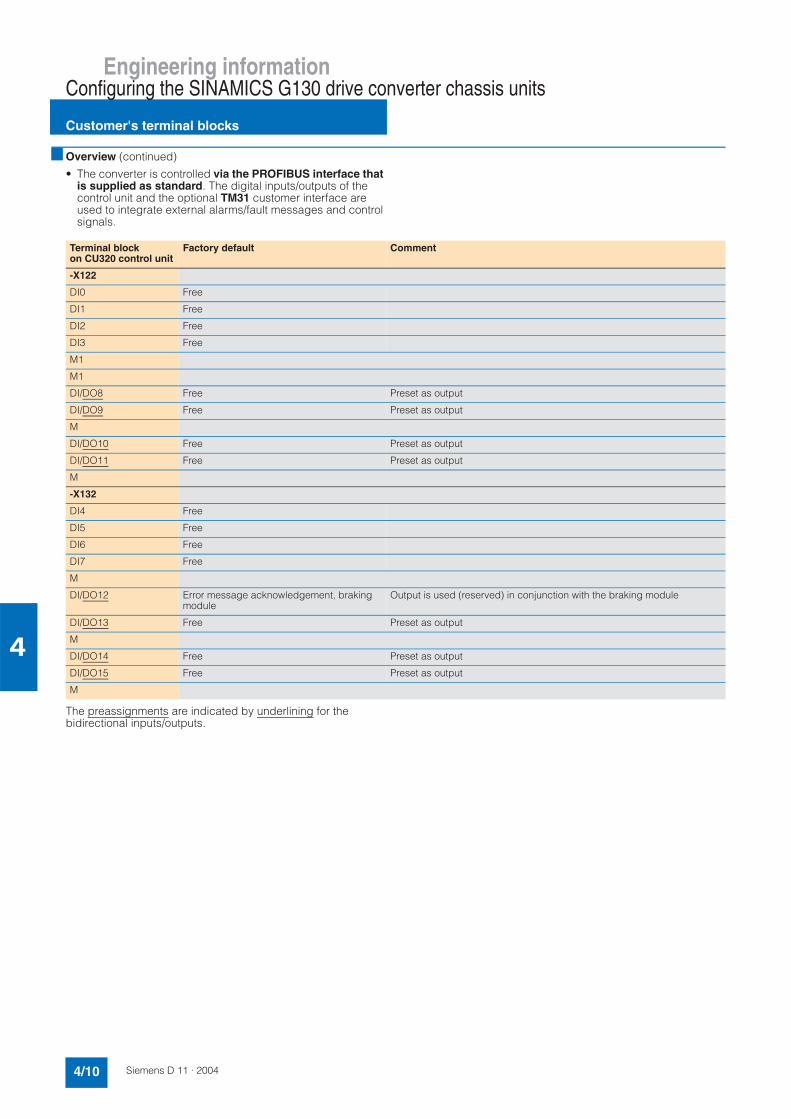
Engineering informationConfiguring the SINAMICS G130 drive converter chassis units
Customer's terminal blocks
4/10 Siemens D 11 · 2004
4
Overview (continued)
• The converter is controlled via the PROFIBUS interface that is supplied as standard. The digital inputs/outputs of the control unit and the optional TM31 customer interface are used to integrate external alarms/fault messages and control signals.
The preassignments are indicated by underlining for the bidirectional inputs/outputs.
Terminal block on CU320 control unit
Factory default Comment
-X122
DI0 Free
DI1 Free
DI2 Free
DI3 Free
M1
M1
DI/DO8 Free Preset as output
DI/DO9 Free Preset as output
M
DI/DO10 Free Preset as output
DI/DO11 Free Preset as output
M
-X132
DI4 Free
DI5 Free
DI6 Free
DI7 Free
M
DI/DO12 Error message acknowledgement, braking module
Output is used (reserved) in conjunction with the braking module
DI/DO13 Free Preset as output
M
DI/DO14 Free Preset as output
DI/DO15 Free Preset as output
M

Engineering informationConfiguring the SINAMICS G130 drive converter chassis units
Customer's terminal blocks
4/11Siemens D 11 · 2004
4
Overview (continued)
The preassignments are indicated by underlining for the bidirectional inputs/outputs.
1) A jumper should be inserted here if these inputs are not used.
Terminal block on TM31 terminal module
Factory default Comment
-X520 Optocoupler inputs connected to common potential
DI0 Free
DI1 Free
DI2 Free
DI3 Acknowledge fault
-X530 Optocoupler inputs connected to common potential
DI4 OFF 2 1) Immediate pulse block, motor coasts
DI5 OFF 3 1) Ramp-down on the fast stop ramp,only of relevance in conjunction with the braking module
DI6 External fault 1)
DI7 Free
-X541 Bidirectional inputs/outputs
DI/DO8 Ready to start message
DI/DO9 Free Preset as input
DI/DO10 Free Preset as input
DI/DO11 External alarm 1) Preset as input
-X542 Relay outputs (changeover contact)
DO0 Inverter enable (operation)
DO1 No fault in converter checkback
-X521 Analog inputs, differential
AI0+ Free
AI0-
AI1+ Free
AI1-
-X522 Analog outputs
AO 0V+ The outputs are set to 0-10 V at the factory.
AO 0V- Actual speed analog output
AO 0C+
AO 1V+ The outputs are set to 0-10 V at the factory.
AO 1V- Actual motor current analog output
AO 1C+
-X522 Thermistor protection
+Temp Input for KTY84 temperature sensor or PTC thermistor
-Temp

Engineering informationConfiguring the SINAMICS G130 drive converter chassis units
Customer's terminal blocks
4/12 Siemens D 11 · 2004
4
Overview (continued)
• The converter is controlled only via the digital inputs/outputs or analog inputs/outputs of the optional TM31 customer in-terface.
The preassignments are indicated by underlining for the bidirectional inputs/outputs.
Terminal block on CU320 control unit
Factory default Comment
-X122
DI0 Free
DI1 Free
DI2 Free
DI3 Free
M1
M1
DI/DO8 Free Preset as output
DI/DO9 Free Preset as output
M
DI/DO10 Free Preset as output
DI/DO11 Free Preset as output
M
-X132
DI4 Free
DI5 Free
DI6 Free
DI7 Free
M
DI/DO12 Error message acknowledgement, braking module
Output is used (reserved) in conjunction with the braking module
DI/DO13 Free Preset as output
M
DI/DO14 Free Preset as output
DI/DO15 Free Preset as output
M

Engineering informationConfiguring the SINAMICS G130 drive converter chassis units
Customer's terminal blocks
4/13Siemens D 11 · 2004
4
Overview (continued)
The preassignments are indicated by underlining for the bidirectional inputs/outputs.
• The converter is controlled and operated only via the optional AOP30 operator panel.The digital inputs/outputs of the CU320 control unit are not used.
1) A jumper should be inserted here if these inputs are not used.
Terminal block on TM31 terminal module
Factory default Comment
-X520 Optocoupler inputs connected to common potential
DI0 ON/OFF 1
DI1 Increase setpoint / fixed setpoint 0 Parameters can be set in the software to determine whether operation is via motorized digital potentiometer or fixed setpoint.
DI2 Decrease setpoint / fixed setpoint 1
DI3 Acknowledge fault
-X530 Optocoupler inputs connected to common potential
DI4 OFF 2 1) Immediate pulse block, motor coasts
DI5 OFF 3 1) Ramp-down on the fast stop ramp,only of relevance in conjunction with the braking module
DI6 External fault 1)
DI7
-X541 Bidirectional inputs/outputs
DI/DO8 Ready to start message
DI/DO9 Free Preset as input
DI/DO10 Free Preset as input
DI/DO11 External alarm 1) Preset as input
-X542 Relay outputs (changeover contact)
DO0 Inverter enable (operation)
DO1 No fault in converter checkback
-X521 Analog inputs, differential
AI0+ Analog input for setting speed setpoint The inputs are set to 10 V at the factory.
AI0-
AI1+ Analog input reserved The inputs are set to 10 V at the factory.
AI1-
-X522 Analog outputs
AO 0V+ The outputs are set to 0-10 V at the factory.
AO 0V- Actual speed analog output
AO 0C+
AO 1V+ The outputs are set to 0-10 V at the factory.
AO 1V- Actual motor current analog output
AO 1C+
-X522 Thermistor protection
+Temp Input for KTY84 temperature sensor or PTC thermistor
-Temp

Engineering informationConfiguring the SINAMICS G130 drive converter chassis units
Line-side components
4/14 Siemens D 11 · 2004
4
Overview
Line fuses
The combined fuses (3NE1.) for line and semiconductor protec-tion are recommended to protect the converter. These fuses are specially adapted to the requirements of the input rectifier's semiconductors to be protected.• Superfast• Adapted to the limit current integral of the semiconductor • Low arc voltage• Improved current limiting (lower let-through values)
See Accessories for order numbers and assignments of these fuses. Please refer to Engineering Information, order no. E20001-A700-P302, for the description and technical data of the fuses.
Line reactor
A line reactor is needed for high system fault levels, partly to pro-tect the actual converter against excessive harmonic currents, and thus against overload, and partly to limit the system pertur-bation to the permitted values. The harmonic currents are limited by the complete inductance comprising the line reactor and mains power input inductance. Line reactors can be omitted if the line infeed inductance is increased sufficiently, i.e. the value of RSC must be sufficiently small.
RSC=Relative Short-Circuit power: Ratio of short-circuit power Sk line at the supply connection point to fundamental apparent output Sconv of the connected converters (to EN 50 178/VDE 0160).
The following applies for SINAMICS G130 drive converter cabinet units:
In practice, the line configuration on which individual converters operate is often not known, i.e. the line short circuit power at the connection point of the converter is not known, so it is recom-mended that a line reactor always be connected in series with the converter.
The line reactor can only be omitted if the values for RSC are lower than those shown in the above table. This is the case when, as shown in the following figure, the converter is con-nected to the line through a transformer with the appropriate rat-ing.
Attention: A line reactor is always needed, however, if a line filter is used.
In this case, the line short-circuit power Sk1 at the connection point of the converter is approximately:
Sk1 = Stransf / (uk transf + Stransf / Sk2 line )
Line filters
The SINAMICS G130 drive converter chassis units have as stan-dard an integral line filter to limit emitted interference and thus conform to the limits for category C3 defined in the product stan-dard EN 61 800-3.
With the optional line filter, the converters are suitable for use in the first environment (category C2), in which case the instruc-tions of the EMC directives should be followed.
If installed correctly and the installation instructions are followed, they may thus be used in the first environment as defined in EN 61 800-3.
The line filter may only be used on grounded supplies (TN sup-plies).Output Line reactor can be omitted Line reactor required
kW for RSC for RSC
< 200 ≤ 43 > 43
200 to 500 ≤ 33 > 33
> 500 ≤ 20 > 20
,
"#,*,&%&"
"
01121.
Symbol Meaning
Stransf Rated output of transformer
uk transf Per-unit impedance of transformer
Sk2 line Short-circuit power of higher-level voltage
,"#7
,
"#,*,&%&"
"#
"#
01121
)

Engineering informationConfiguring the SINAMICS G130 drive converter chassis units
Components in the DC link
4/15Siemens D 11 · 2004
4
Overview
Braking units
Braking units are used when regenerative energy occurs occa-sionally and briefly, for example when the brake is applied to the drive (emergency stop). The braking units comprise a braking module and a load resistor, which must be attached externally.
Braking units with braking powers of 200 kW are available for the SINAMICS G130 drive converter chassis units. For higher brak-ing powers, braking units can be connected in parallel for larger converters (on request).
A thermal contact, which can be integrated into the converter's alarm and shutdown sequence, is installed in the braking resis-tor for monitoring.
Determining the required braking units and braking resistors• For periodic duty cycles with a load duration of ≤ 90 s, the
mean braking power value within this duty cycle must be de-termined. The relevant period should be used as the time base.
• For periodic duty cycles with a load duration of ≥ 90 s or for sporadic braking operations, a 90 s time segment in which the greatest mean value occurs should be selected. A 90 s period should be set as the time base.
When selecting the braking units (braking module and braking resistor), consider both the mean braking power value and the required peak braking power.
Basic data
Load diagram
Calculating the P20 power
To reduce the voltage stress on the motor and converter, the re-sponse threshold at which the braking unit is activated and the DC link voltage generated can be reduced. For example, the DC link voltage for the converters in the voltage range from 380 V to 480 V can be reduced from 774 V to 673 V. This also reduces the possible peak power. A factor of 1.06, rather than a factor of 0.8 should be used.
The ON/OFF states of the braking module are controlled by a 2-point controller. The respective response thresholds are shown in the following table:
Supply voltage
380 V to 480 V 660 V to 690 V
SINAMICS G130 drive converter chassis unitsPower module
315 kW to 560 kW 315 kW to 800 kW
Braking moduleContinuous power PDB
50 kW 50 kW
Braking modulePower P40
100 kW 100 kW
Braking moduleRated power P20
200 kW 200 kW
Braking modulePeak power P15
250 kW 250 kW
Braking resistor RB 2,2 Ω ±7.5% 4,9 Ω ±7.5%
Max. current 378 A 255 A
Converter voltage range Braking unit response threshold
380 V to 480 V 774 V (673 V)
660 V to 690 V 1158 V (1070 V)
(7"4"9,*(:(&,&*++#,7##4!;##(<:(&,&*++#,7##4!;##(:(&,&*++#,7##4!;#<#
8
. < 3 = 5 ;
01121.
8=
8
8
#
8
8
>
?
?
?
(85:",*
!#
01121.3
",*:85
(<8:"4"9,*
(<8:"4"9,*

Engineering informationConfiguring the SINAMICS G130 drive converter chassis units
Components in the DC link
4/16 Siemens D 11 · 2004
4
Overview (continued)
Example
The design of the braking module and braking resistor is to be defined for a 450 kW power module.
The mean braking power is calculated as follows:
Mean braking power = 150 kW x 20 s / 90 s = 33.3 kW
P20 = 4.5 x 33.3 kW = 150 kW
Peak power = 0.8 x 150 kW = 120 kW
Result:
The mean braking power is the determining factor in the config-uration of the braking module and braking resistor, i.e. a braking unit ≥ 150 kW should be provided.
The 200 kW braking unit should be selected.
When the response threshold is reduced, the required braking power P20 is calculated as follows:
Mean braking power = 150 kW x 20 s / 90 s = 33.3 kW
P20 = 4.5 x 33.3 kW = 150 kW
Peak power = 1.06 x 150 kW = 159 kW
Result:
The peak power to be generated is the determining factor in the configuration of the braking module and braking resistor, i.e. a braking unit ≥ 159 kW should be provided.
The 200 kW braking unit should be selected.
#
"4"9,*
011213
;#
. < 3 = 5 ; #

Engineering informationConfiguring the SINAMICS G150 drive converter cabinet units
Dimensioning and selection information
4/17Siemens D 11 · 2004
4
Overview
Rated data and continuous operation of converters for drives with low demands on control performance
SINAMICS G150 converter cabinet units are designed for appli-cations with low demands on dynamic response and control ac-curacy, offering no possibility of regenerative feedback.
They are designed for motorized operation at the supply volt-ages specified in the selection tables. These values take ac-count of voltage fluctuations within the defined tolerances.
The currents specified in the selection and ordering data are available across the entire frequency/speed setting range.
As far as the rated currents are concerned, the units are dimen-sioned for continuous operation with the specified rated output currents. The values are based on 6-pole Siemens standard mo-tors.
Degrees of protection of the drive converter cabinet units
The EN 60 529 standard covers the protection of electrical equipment by means of housings, covers or equivalent, and in-cludes:• Protection of persons against accidental contact with live or
moving parts within the housing and protection of the equip-ment against the penetration of solid foreign matter (shock protection)
• Protection of the equipment against the penetration of water(water protection)
• Abbreviations for the internationally agreed degrees of protec-tion.
The degrees of protection are specified by abbreviations com-prising the code letters IP and two digits.
EMERGENCY STOP functions
The EMERGENCY STOP function may be essential for certain drive applications. According to EN 60 204, an EMERGENCY STOP must be designed as a stop of category 0 or as a stop of category 1.
They are defined as follows:
Stop of category 0:
Uncontrolled shutdown by immediately switching off the power supply. Motor coasts. This corresponds to immediate stopping of the inverter, in association with intrinsically-safe disconnection of the main contactors or - for greater outputs - of the circuit-breaker.
Stop of category 1:
Controlled shutdown, where the power supply is retained until standstill is reached. This can be implemented by means of a rapid stop in association with intrinsically-safe disconnection of the main contactors or the circuit-breaker.
Comment:
Only a stop of category 0 is sensible for converters that do not have braking facilities. An EMERGENCY STOP with a stop of category 1 generally requires a braking facility (braking unit or converter with regenerative feedback).
The category must be selected using a risk evaluation for the drive.
To achieve this, the drives can be roughly divided into the follow-ing groups:
Case A:
Drives that are quickly braked to zero speed by the connected load when they are shut down.
Typical example: Pumps. For these, an EMERGENCY STOP with category 0 is sufficient.
Case B:
Drives with larger rotating masses that are braked to zero speed by the connected load when they are shut down.
Typical example: Fans.For these, an EMERGENCY STOP with category 0 is sufficient if the coasting time can be tolerated. On the other hand, if stop-ping is required within a specified time when an EMERGENCY STOP occurs, it may be necessary to provide an EMERGENCY STOP according to category 1. This may require a braking facil-ity even if it is not needed for the actual drive application.
Degree of protection of the drive converter cabinet unit
First digit(protection against accidental contact and solid matter)
Second digit(protection of the equipment against the penetration of water)
IP20 Protected against solid mat-ter, diameter ≥ 12.5 mm
No water protection
IP21 Protected against solid mat-ter, diameter ≥ 12.5 mm
Protected against drip water.Vertically falling drip water must not have a harmful effect
IP23 Protected against solid mat-ter, diameter ≥ 12.5 mm
Protected against spray water.Water sprayed on both sides of the vertical at an angle of up to 60° must not have a harmful effect
IP54 Dust protected.Entry of dust is not totally prevented, but the entry of dust is not allowed in such quantities that the operation of equipment or the safety will be impaired.
Protected against water from a hose.Water from a hose which is directed on the enclo-sure must not have a harmful effect.

Engineering informationConfiguring the SINAMICS G150 drive converter cabinet units
Customer's terminal block
4/18 Siemens D 11 · 2004
4
Overview
The following factory settings are provided to simplify configur-ing the customer interface and commissioning. The interfaces can also be assigned as required.
The preassignments are indicated by underlining for the bidirectional inputs/outputs.
1) A jumper should be inserted here if these inputs are not used.
Terminal block on TM31 terminal module
Factory default Comment
-X520 Optocoupler inputs connected to common potential
DI0 ON/OFF 1
DI1 Increase setpoint / fixed setpoint 0 Parameters can be set in the software to determine whether operation is via motorized digital potentiometer or fixed setpoint.
DI2 Decrease setpoint / fixed setpoint 1
DI3 Acknowledge fault
-X530 Optocoupler inputs connected to common potential
DI4 Inverter enable 1) Converter is at standby and waiting for the enable signal
DI5 OFF 3 1) Ramp-down on the fast stop ramp,only of relevance in conjunction with the braking module
DI6 External fault 1)
DI7
-X541 Bidirectional inputs/outputs
DI/DO8 Ready to start message
DI/DO9 Free Preset as input
DI/DO10 Free Preset as input
DI/DO11 Free Preset as input
-X542 Relay outputs (changeover contact)
DO 0 Inverter enable (operation)
DO 1 No fault in converter checkback
-X521 Analog inputs, differential
AI0+ Analog input for setting speed setpoint The inputs are set to 0-20 mA at the factory.
AI0-
AI1+ Analog input reserved The inputs are set to 0-20 mA at the factory.
AI1-
-X522 Analog outputs
AO 0V+ The outputs are set to 0-20 mA at the factory.
AO 0V- Actual speed analog output
AO 0C+
AO 1V+ The outputs are set to 0-20 mA at the factory.
AO 1V- Actual motor current analog output
AO 1C+
-X522 Thermistor protection
+Temp Input for KTY84 temperature sensor or PTC thermistor
-Temp

Engineering informationConfiguring the SINAMICS G150 drive converter cabinet units
Conductor cross-sections and terminals
4/19Siemens D 11 · 2004
4
Overview
The following table shows the recommended or maximum per-missible cable connections on the power supply and motor sides.
The recommended cross-sections are based on the listed fuses and with single routing of the three-wire cables at an ambient temperature of 40 °C.
In the case of different conditions (cable routing, cable group-ing, ambient temperature), the planning instructions for routing the cables must be taken into account.
Out-put
Converter Wght. Line connection Motor connection Cabinet earthing
(stan-dard ver-sion)
Recommendedcross-section
Maximumconductorcross-section
Mountingscrew M12
Recommendedcross-section
Maximumconductor cross-section
Mount-ing screw M12
Mountingscrew M12
Comment
kW Type
6SL3710 - ...
kg DINVDEmm2
AWG/ MCM
DINVDEmm2
AWG/ MCM
(No. of holes)
DINVDEmm2
AWG/ MCM
DINVDEmm2
AWG/ MCM
(No. of holes)
(No. of holes)
Version A, 380 V to 480 V 110 -1GE32-1AA0 320 2x70 2x(000) 4x240 4x600 (2) 2x70 2x(000) 2x150 2x(400) (2) (2)132 -1GE32-6AA0 320 2x95 2x(4/0) 4x240 4x600 (2) 2x95 2x(4/0) 2x150 2x(400) (2) (2)160 -1GE33-1AA0 390 2x120 2x(300) 4x240 4x600 (2) 2x120 2x(300) 2x150 2x(400) (2) (2)200 -1GE33-8AA0 480 2x120 2x(300) 4x240 4x600 (2) 2x120 2x(300) 2x150 2x(400) (2) (2)250 -1GE35-0AA0 480 2x185 2x(500) 4x240 4x600 (2) 2x185 2x(500) 2x240 2x(600) (2) (2)315 -1GE36-1AA0 860 2x240 2x(600) 4x240 4x600 (2) 2x240 2x(600) 4x240 4x(600) (2) (2)400 -1GE37-5AA0 865 2x300 2x(800) 4x240 4x600 (2) 2x300 2x(800) 4x240 4x(600) (2) (10) Cu rail450 -1GE38-4AA0 1075 4x150 4x(400) 8x240 8x600 (4) 4x150 4x(400) 4x240 4x(600) (2) (16) Cu rail560 -1GE41-0AA0 1360 4x185 4x(500) 8x240 8x600 (4) 4x185 4x(500) 6x240 6x(600) (3) (18) Cu railVersion A, 660 V to 690 V 75 -1GH28-5AA0 320 50 (00) 4x240 4x600 (2) 50 (00) 2x70 2x(000) (2) (2)90 -1GH31-0AA0 320 50 (00) 4x240 4x600 (2) 50 (00) 2x150 2x(400) (2) (2)110 -1GH31-2AA0 320 70 (000) 4x240 4x600 (2) 70 (000) 2x150 2x(400) (2) (2)132 -1GH31-5AA0 320 95 (4/0) 4x240 4x600 (2) 95 (4/0) 2x150 2x(400) (2) (2)160 -1GH31-8AA0 390 120 (300) 4x240 4x600 (2) 120 (300) 2x150 2x(400) (2) (2)200 -1GH32-2AA0 390 2x70 2x(000) 4x240 4x600 (2) 2x70 2x(000) 2x150 2x(400) (2) (2)250 -1GH32-6AA0 390 2x95 2x(4/0) 4x240 4x600 (2) 2x95 2x(4/0) 2x185 2x(500) (2) (2)315 -1GH33-3AA0 390 2x120 2x(300) 4x240 4x600 (2) 2x120 2x(300) 2x240 2x(600) (2) (2)400 -1GH34-1AA0 860 2x185 2x(500) 4x240 4x600 (2) 2x185 2x(500) 4x240 4x600 (2) (2)450 -1GH34-7AA0 860 2x185 2x(500) 4x240 4x600 (2) 2x185 2x(500) 4x240 4x600 (2) (2)560 -1GH35-8AA0 860 2x240 2x(600) 4x240 4x600 (2) 2x240 2x(600) 4x240 4x600 (2) (2)710 -1GH37-4AA0 1320 3x185 3x(500) 8x240 8x600 (4) 3x185 3x(500) 6x240 6x600 (3) (18) Cu rail800 -1GH38-1AA0 1360 4x150 4x(400) 8x240 8x600 (4) 4x150 4x(400) 6x240 6x600 (3) (18) Cu rail
Version C, 380 V to 480 V 110 -1GE32-1CA0 225 2x70 2x(000) 2x240 2x600 (1) 2x70 2x(000) 2x150 2x(400) (1) (2)132 -1GE32-6CA0 225 2x95 2x(4/0) 2x240 2x600 (1) 2x95 2x(4/0) 2x150 2x(400) (1) (2)160 -1GE33-1CA0 300 2x120 2x(300) 2x240 2x600 (1) 2x120 2x(300) 2x150 2x(400) (1) (2)200 -1GE33-8CA0 300 2x120 2x(300) 2x240 2x600 (1) 2x120 2x(300) 2x150 2x(400) (1) (2)250 -1GE35-0CA0 300 2x185 2x(500) 2x240 2x600 (1) 2x185 2x(500) 2x240 2x(600) (1) (2)315 -1GE36-1CA0 670 2x240 2x(600) 8x240 8x600 (4) 2x240 2x(600) 8x240 8x(600) (4) (2)400 -1GE37-5CA0 670 2x300 2x(800) 8x240 8x600 (4) 2x300 2x(800) 8x240 8x(600) (4) (8) Cu rail450 -1GE38-4CA0 670 4x150 4x(400) 8x240 8x600 (4) 4x150 4x(400) 8x240 8x(600) (4) (8) Cu rail560 -1GE41-0CA0 980 4x185 4x(500) 8x240 8x600 (4) 4x185 4x(500) 8x240 8x(600) (4) (10) Cu railVersion C, 660 V to 690 V 75 -1GH28-5CA0 225 50 (00) 2x240 2x600 (1) 50 (00) 2x70 2x(000) (1) (2)90 -1GH31-0CA0 225 50 (00) 2x240 2x600 (1) 50 (00) 2x150 2x(400) (1) (2)110 -1GH31-2CA0 225 70 (000) 2x240 2x600 (1) 70 (000) 2x150 2x(400) (1) (2)132 -1GH31-5CA0 225 95 (4/0) 2x240 2x600 (1) 95 (4/0) 2x150 2x(400) (1) (2)160 -1GH31-8CA0 300 120 (300) 2x240 2x600 (1) 120 (300) 2x150 2x(400) (1) (2)200 -1GH32-2CA0 300 2x70 2x(000) 2x240 2x600 (1) 2x70 2x(000) 2x150 2x(400) (1) (2)250 -1GH32-6CA0 300 2x95 2x(4/0) 2x240 2x600 (1) 2x95 2x(4/0) 2x185 2x(500) (1) (2)315 -1GH33-3CA0 300 2x120 2x(300) 4x240 4x600 (1) 2x120 2x(300) 2x240 2x(600) (1) (2)400 -1GH34-1CA0 670 2x185 2x(500) 4x240 4x600 (2) 2x185 2x(500) 4x240 4x600 (2) (2)450 -1GH34-7CA0 670 2x185 2x(500) 4x240 4x600 (2) 2x185 2x(500) 4x240 4x600 (2) (2)560 -1GH35-8CA0 670 2x240 2x(600) 4x240 4x600 (2) 2x240 2x(600) 4x240 4x600 (2) (2)710 -1GH37-4CA0 940 3x185 3x(500) 8x240 8x600 (4) 3x185 3x(500) 6x240 6x600 (3) (18) Cu rail800 -1GH38-1CA0 980 4x150 4x(400) 8x240 8x600 (4) 4x150 4x(400) 6x240 6x600 (3) (18) Cu rail

Engineering informationConfiguring the SINAMICS G150 drive converter cabinet units
Conductor cross-sections and terminals
4/20 Siemens D 11 · 2004
4
Overview
Required cable cross-sections for line and motor connections
It is always recommendable to use 3-wire three-phase cables or to connect several cables of this type in parallel. There are two main reasons for this:• In this manner, the high IP55 degree of protection or better can
be achieved for the motor terminal box without any problems because the cables are introduced into the terminal box via screwed glands and the number of possible glands is limited by the geometry of the terminal box. Single cables are less suitable.
• With three-phase cables, the summed ampere-turns over the cable outer diameter is equal to zero and they can be routed in (conductive, metal) cable ducts or racks without any notice-able currents (earth current or leakage current) being induced in these conductive, metal connections. The danger of in-duced leakage currents and thus of increased cable sheath losses is greater for single cables .
The cable cross-section required depends on the current trans-mitted in the cable. The permissible current load on cables is de-fined e.g. in DIN VDE 0298 Part 2 / DIN VDE 0276-1000. It de-pends partly on the ambient conditions such as temperature and partly on the type of routing. When laid singly, the cables are cooled relatively well. Where there are several cables routed to-gether, they can heat each other up, and thus receive much poorer ventilation. In this context, please refer to the applicable reduction factors for these boundary conditions in DIN VDE 0298 Part 2 / DIN VDE 0276-1000. With an ambient temperature of 40 °C, the cross-sections of copper cables can be based on the following table.
Current loading according to DIN VDE 0298 Part 2 at 40 °C
With higher currents, cables must be connected in parallel.
Earthing
Required PE conductor cross-sections:
The PE conductor must be dimensioned taking into account the following data:• In the event of an earth fault, no impermissibly high contact
voltages may occur (< AC 50 V or < DC 120 V, EN 50 178 Section 5.3.2.2, IEC 60 364, IEC 60 543) as a result of voltage drops of the earth fault current on the PE conductor.
• The earth fault current flowing in the PE conductor in the event of an earth fault must not place an impermissible load on the PE conductor.
• If it is possible in the event of a fault according to EN 50 178 Section 8.3.3.4 that continuous currents can flow via the PE conductor, the cross-section of the PE conductor must be di-mensioned according to this continuous current.
• The cross-section of the PE conductor must be selected ac-cording to EN 60 2041, EN 60 439-1, IEC 60 364.
• Switchgear and motors are usually earthed separately with a local earth electrode. With this constellation, the earth fault current flows via the parallel earth connections and is divided. With this earthing, no impermissible contact voltages can oc-cur, despite the PE conductor cross-sections used in the above table. From our experience with different earthing con-figurations, however, we recommend that the earth wire from the motor should be routed directly back to the converter. For EMC reasons and to prevent shaft currents, symmetrical motor cables and not four-wire cables should be used here. The earth connection (PE) must be routed separately or arranged symmetrically in the motor cable. The symmetry of the PE con-ductor is achieved using a conductor surrounding all phase conductors or using a cable with a symmetrical arrangement of the three phase conductors and three earth conductors.
• By means of their fast closed-loop control, the converters limit the load current (motor and earth fault currents) to an rms value corresponding to the rated current. Because of this, we recommend use of a PE conductor cross-section that is anal-ogous to the outer conductor cross-section for earthing the control cabinet.
Cross-section of 3-wire cables
Withsinglerouting
With multiple routing on a common cable rack
mm2 A A
50 138 95
70 176 121
95 212 146
120 245 169
150 282 194
185 323 222
240 380 261
300 418 289
Cross-section of outer conductor
Minimum cross-section of external PE conductor
Up to 16 mm2 At least cross-section of outer conductor
16 mm2 to 35 mm2 16 mm2
Above 35 mm2 At least half the cross-section of outer conductor

Engineering informationConfiguring the SINAMICS G150 drive converter cabinet units
Line-side components
4/21Siemens D 11 · 2004
4
Overview
Line fuses
The combined fuses (3NE1.) for line and semiconductor protec-tion are recommended to protect the converter. These fuses are specially adapted to the requirements of the input rectifier's semiconductors to be protected.• Superfast• Adapted to the limit current integral of the semiconductor • Low arc voltage• Improved current limiting (lower let-through values)
See Accessories for order numbers and assignments of these fuses. Please refer to Engineering Information, order no. E20001-A700-P302, for the description and technical data of the fuses.
Line reactor
A line reactor is needed for high system fault levels, partly to pro-tect the actual converter against excessive harmonic currents, and thus against overload, and partly to limit the system pertur-bation to the permitted values. The harmonic currents are limited by the complete inductance comprising the line reactor and mains power input inductance. Line reactors can be omitted if the line infeed inductance is increased sufficiently, i.e. the value of RSC must be sufficiently small.
RSC=Relative Short-Circuit power: Ratio of short-circuit power Sk line at the supply connection point to fundamental apparent output Sconv of the connected converters (to EN 50 178/VDE 0160).
The following applies for SINAMICS G150 drive converter cabinet units:
In practice, the line configuration on which individual converters operate is often not known, i.e. the line short circuit power at the connection point of the converter is not known, so it is recom-mended that a line reactor always be connected in series with the converter. For this reason, the drive converter cabinet units up to an output of 500 kW are always equipped as standard with a 2% line reactor.
The line reactor can only be omitted (L22 option) if the values for RSC are lower than those shown in the above table. This is the case when, as shown in the following figure, the converter is connected to the line through a transformer with the appropriate rating.
In this case, the line short-circuit power Sk1 at the connection point of the converter is approximately:
Sk1 = Stransf / (uk transf + Stransf / Sk2 line )
Large output converters should ideally be connected to me-dium-voltage supplies via transformers in view of the system perturbation, so cabinet units over 500 kW have no line reactors as standard.
A line reactor (L23 option) is always required, however, if• for cabinet units > 500 kW, the RSC ratio is > 20 or• a line filter is used.
Line filters
The SINAMICS G150 drive converter cabinet units have as stan-dard an integral line filter to limit emitted interference and thus conform to the limits for category C3 defined in the product stan-dard EN 61 800-3.
With the optional line filter, the converters are suitable for use in the first environment (category C2), in which case the instruc-tions of the EMC directives should be followed.
If installed correctly and the installation instructions are followed, they may thus be used in the first environment as defined in EN 61 800-3.
The line filter may only be used on grounded supplies (TN sup-plies).
Output Line reactor can be omitted
Line reactor required
kW for RSC Order code (option)
for RSC Order code (option)
< 200 ≤ 43 L22 > 43 -
200 to 500 ≤ 33 L22 > 33 -
> 500 ≤ 20 - > 20 L23
,
"#,*,&%&"
"
01121.
Symbol Meaning
Stransf Rated output of transformer
uk transf Per-unit impedance of transformer
Sk2 line Short-circuit power of higher-level voltage
,"#7
,
"#,*,&%&"
"#
"#
01121
)
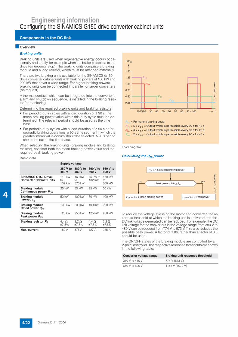
Engineering informationConfiguring the SINAMICS G150 drive converter cabinet units
Components in the DC link
4/22 Siemens D 11 · 2004
4
Overview
Braking units
Braking units are used when regenerative energy occurs occa-sionally and briefly, for example when the brake is applied to the drive (emergency stop). The braking units comprise a braking module and a load resistor, which must be attached externally.
There are two braking units available for the SINAMICS G150 drive converter cabinet units with braking powers of 100 kW and 200 kW that cover a wide range. For higher braking powers, braking units can be connected in parallel for larger converters (on request).
A thermal contact, which can be integrated into the converter's alarm and shutdown sequence, is installed in the braking resis-tor for monitoring.
Determining the required braking units and braking resistors• For periodic duty cycles with a load duration of ≤ 90 s, the
mean braking power value within this duty cycle must be de-termined. The relevant period should be used as the time base.
• For periodic duty cycles with a load duration of ≥ 90 s or for sporadic braking operations, a 90 s time segment in which the greatest mean value occurs should be selected. A 90 s period should be set as the time base.
When selecting the braking units (braking module and braking resistor), consider both the mean braking power value and the required peak braking power.
Basic data
Load diagram
Calculating the P20 power
To reduce the voltage stress on the motor and converter, the re-sponse threshold at which the braking unit is activated and the DC link voltage generated can be reduced. For example, the DC link voltage for the converters in the voltage range from 380 V to 480 V can be reduced from 774 V to 673 V. This also reduces the possible peak power. A factor of 1.06, rather than a factor of 0.8 should be used.
The ON/OFF states of the braking module are controlled by a 2-point controller. The respective response thresholds are shown in the following table:
Supply voltage
380 V to 480 V
380 V to 480 V
660 V to 690 V
660 V to 690 V
SINAMICS G150 Drive Converter Cabinet Units
110 kW to132 kW
160 kW to570 kW
75 kW to 132 kW
160 kW to800 kW
Braking moduleContinuous power PDB
25 kW 50 kW 25 kW 50 kW
Braking modulePower P40
50 kW 100 kW 50 kW 100 kW
Braking moduleRated power P20
100 kW 200 kW 100 kW 200 kW
Braking modulePeak power P15
125 kW 250 kW 125 kW 250 kW
Braking resistor RB 4,4 Ω±7.5%
2,2 Ω±7.5%
4,4 Ω±7.5%
2,2 Ω±7.5%
Max. current 189 A 378 A 127 A 255 A
Converter voltage range Braking unit response threshold
380 V to 480 V 774 V (673 V)
660 V to 690 V 1158 V (1070 V)
(7"4"9,*(:(&,&*++#,7##4!;##(<:(&,&*++#,7##4!;##(:(&,&*++#,7##4!;#<#
8
. < 3 = 5 ;
01121.
8=
8
8
#
8
8
>
?
?
?
(85:",*
!#
01121.3
",*:85
(<8:"4"9,*
(<8:"4"9,*

Engineering informationConfiguring the SINAMICS G150 drive converter cabinet units
Components in the DC link
4/23Siemens D 11 · 2004
4
Overview (continued)
Example
The design of the braking unit is to be defined for a 132 kW drive converter cabinet unit.
The mean braking power is calculated as follows:
Mean braking power = 90 kW x 17 s / 90 s = 17.0 kW
P20 = 4.5 x 17.0 kW = 76.5 kW
Peak power = 0.8 x 90 kW = 72.0 kW
Result:
The mean braking power is the determining factor in the config-uration of the braking module and braking resistor, i.e. a braking unit ≥ 76.5 kW should be provided.
The 100 kW braking unit should be selected.
When the response threshold is reduced, the required braking power P20 is calculated as follows:
Mean braking power = 90 kW x 17 s / 90 s = 17.0 kW
P20 = 4.5 x 17.0 kW = 76.5 kW
Peak power = 1.06 x 90 kW = 95.4 kW
Result:
The peak power to be generated is the determining factor in the configuration of the braking module and braking resistor, i.e. a braking unit ≥ 95.4 kW should be provided.
The 100 kW braking unit should be selected.
#
"4"9,*
011213
;#
. < 3 = 5 ; #

Engineering informationDimensioning drives
Dimensioning drives
4/24 Siemens D 11 · 2004
4
Overview
Drives with quadratic load torque
Drives with a quadratic load torque (M~n2), such as used for pumps and fans, require the full torque at the rated speed.
Increased starting torques or high load surges do not usually oc-cur. It is therefore unnecessary to provide a higher overload ca-pability for the converter.
The following applies to selection of a suitable converter for drives with a quadratic load torque:
The rated current of the converter must be at least as large as the motor current at full torque in the required load point.
If 1LG4/1LG6 and 1LA8 standard motors are used, these motors can be loaded with the full rated power, even in converter mode. They are then utilized to full advantage according to temperature class F. However, if the motors may only be utilized according to temperature class B, the motor output must be reduced by 10%.
Selection of suitable motors and converters for a specific appli-cation is supported by the SIZER configuration program.
Typical curve for the permissible torque for self-ventilated motors (e.g. 1LA) with a rated frequency of 50 Hz
Drives with constant load torque
The 1LG4/1LG6 and 1LA8 self-ventilated motors cannot provide their full rated torques throughout the entire speed range in con-tinuous operation. The continuous permissible torque decreases as the speed decreases because of the reduced cooling effect (see diagram).
Depending on the speed range, the torque - and thus the power - must be reduced for the self-ventilated motors.
In the case of 1PQ8 and 1PQ4 forced-ventilated motors, it is not necessary to reduce the output, or only by a relatively small amount, depending on the speed range.
For frequencies above the rated frequency fn (50 Hz in the dia-gram), the motors are driven in the field weakening range. The usable torque is reduced in this case by approx. fn/f, and the out-put remains constant. An adequate distance of ≥ 30% must be maintained with respect to the breakdown torque, especially in control modes with V/f characteristics. This interval is reduced by (fn/f)².
The selected base load current of the converter should therefore be at least as great as the motor current at full torque at the re-quired load point.
Selection of suitable motors and converters for a specific appli-cation is supported by the SIZER configuration program.
Rated current – permissible and non-permissible motor/converter combinations
Motor rated current greater than converter rated current:
If a motor is used whose rated current is greater than the rated converter current, this means that the motor can only be oper-ated at partial load. The following limit must be observed:
The maximum possible converter current (overload current) should be greater than or equal to the rated current of the con-nected motor.
If this dimensioning instruction is not observed, current peaks which can either lead to switching-off or can cause a continuous reduction in output by the internal protection circuit can occur as a result of the low leakage inductance of larger motors.
Rated motor current much smaller than converter rated current:
The rated motor current for the sensorless vector control used must be at least ¼ of the rated converter current. With smaller motor currents, operation using the V/f control mode is possible.
)
;
5
=
3
. < 3 = 5 @A
>
#"&:"9
%*"9"9
+%"
BA""%97,"&"##
01121<4
BA""%97,"&"##?
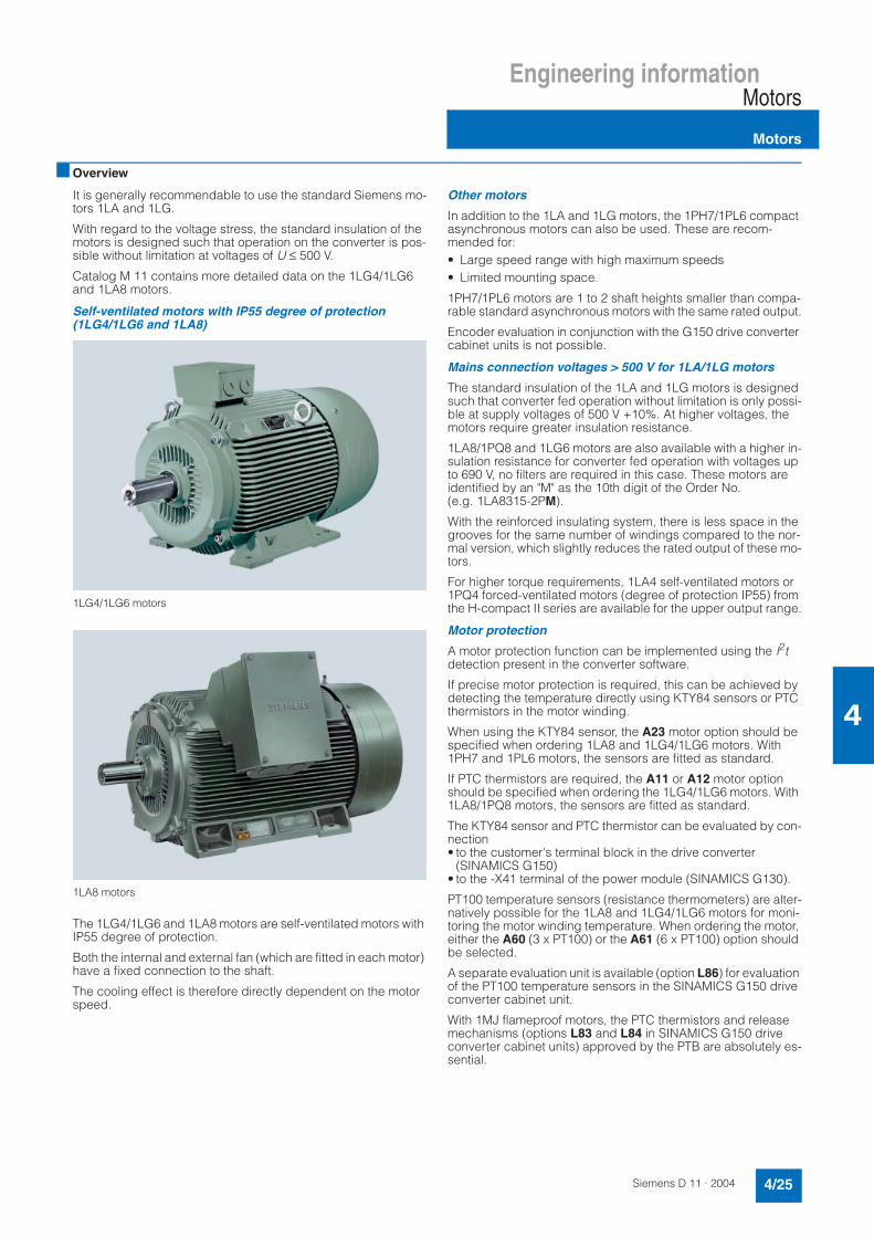
Engineering informationMotors
Motors
4/25Siemens D 11 · 2004
4
Overview
It is generally recommendable to use the standard Siemens mo-tors 1LA and 1LG.
With regard to the voltage stress, the standard insulation of the motors is designed such that operation on the converter is pos-sible without limitation at voltages of U ≤ 500 V.
Catalog M 11 contains more detailed data on the 1LG4/1LG6 and 1LA8 motors.
Self-ventilated motors with IP55 degree of protection (1LG4/1LG6 and 1LA8)
1LG4/1LG6 motors
1LA8 motors
The 1LG4/1LG6 and 1LA8 motors are self-ventilated motors with IP55 degree of protection.
Both the internal and external fan (which are fitted in each motor) have a fixed connection to the shaft.
The cooling effect is therefore directly dependent on the motor speed.
Other motors
In addition to the 1LA and 1LG motors, the 1PH7/1PL6 compact asynchronous motors can also be used. These are recom-mended for:• Large speed range with high maximum speeds• Limited mounting space.
1PH7/1PL6 motors are 1 to 2 shaft heights smaller than compa-rable standard asynchronous motors with the same rated output.
Encoder evaluation in conjunction with the G150 drive converter cabinet units is not possible.
Mains connection voltages > 500 V for 1LA/1LG motors
The standard insulation of the 1LA and 1LG motors is designed such that converter fed operation without limitation is only possi-ble at supply voltages of 500 V +10%. At higher voltages, the motors require greater insulation resistance.
1LA8/1PQ8 and 1LG6 motors are also available with a higher in-sulation resistance for converter fed operation with voltages up to 690 V, no filters are required in this case. These motors are identified by an "M" as the 10th digit of the Order No. (e.g. 1LA8315-2PM).
With the reinforced insulating system, there is less space in the grooves for the same number of windings compared to the nor-mal version, which slightly reduces the rated output of these mo-tors.
For higher torque requirements, 1LA4 self-ventilated motors or 1PQ4 forced-ventilated motors (degree of protection IP55) from the H-compact II series are available for the upper output range.
Motor protection
A motor protection function can be implemented using the I2tdetection present in the converter software.
If precise motor protection is required, this can be achieved by detecting the temperature directly using KTY84 sensors or PTC thermistors in the motor winding.
When using the KTY84 sensor, the A23 motor option should be specified when ordering 1LA8 and 1LG4/1LG6 motors. With 1PH7 and 1PL6 motors, the sensors are fitted as standard.
If PTC thermistors are required, the A11 or A12 motor option should be specified when ordering the 1LG4/1LG6 motors. With 1LA8/1PQ8 motors, the sensors are fitted as standard.
The KTY84 sensor and PTC thermistor can be evaluated by con-nection• to the customer's terminal block in the drive converter
(SINAMICS G150)• to the -X41 terminal of the power module (SINAMICS G130).
PT100 temperature sensors (resistance thermometers) are alter-natively possible for the 1LA8 and 1LG4/1LG6 motors for moni-toring the motor winding temperature. When ordering the motor, either the A60 (3 x PT100) or the A61 (6 x PT100) option should be selected.
A separate evaluation unit is available (option L86) for evaluation of the PT100 temperature sensors in the SINAMICS G150 drive converter cabinet unit.
With 1MJ flameproof motors, the PTC thermistors and release mechanisms (options L83 and L84 in SINAMICS G150 drive converter cabinet units) approved by the PTB are absolutely es-sential.

Engineering informationMotors
Motors
4/26 Siemens D 11 · 2004
4
Overview (continued)
Bearing currents
A high clock frequency of the output voltage is required to pro-vide the motor with currents which are as sinusoidal as possible (smooth running, oscillation torque, additional losses). The re-sulting steep voltage pulses cause capacitive charge reversal currents in the existing capacities (motor cables and windings). This physical effect is particularly evident with larger motors. The circuit may be closed via the bearings and the high-frequency capacitive current pulses may destroy the bearings in a worst-case scenario. To avoid this risk, it is recommended that the bearings at the non-drive-end of the motor are isolated in the case of converter-fed motors.
The isolated bearing is standard for all 1LA8 motors that are des-ignated for converter operation.
An isolated bearing on the non-drive end is available as an op-tion for motors of the 1LG4/1LG6 series starting at frame size 280 (Order code L27).
An additional measure for reducing the bearing currents even further is to use a motor reactor, shielded motor cables and good earthing of the motor housing. It is recommended to route the earth cable from the motor directly to the converter.
Since these processes involve high frequencies, asymmetry in the circuits must be kept to a minimum. Only symmetrical multi-core motor cables must be used (do not use single or four-con-ductor cables!). The ground connection (protective conductor, PE) must be arranged symmetrically in the motor cable to pre-vent shaft currents with base frequencies. The symmetry of the PE conductor is achieved with a conductor that surrounds all the phase conductors or a cable in which the three phase conduc-tors and three ground conductors are arranged symmetrically.
Operation with and without feedback of the actual speed value
The control range of the drive must be taken into account with regard to the speed accuracy.
If the speed control range is above 5% of the rated speed, the control accuracy of the sensorless vector control is approx. 0.2 x fslip. Taking into account the slip values of standard motors in the output range from 75 kW to 800 kW, this results in a speed accuracy of <0.2%. In the speed control range below 5% of the rated speed, the control accuracy is approximately that of the slip frequency of the motor, i.e. approx. 1%.
The SINAMICS G130/G150 drive converters can be operated with or without feedback of the actual speed value.
Use of encoders to measure the actual speed value of the motor is recommended with:• High dynamic response and torque accuracy requirements• Very high speed accuracy• Observation of a defined torque with speeds below 5% of the
rated motor speed.
Operation of motors with flameproof enclosure "d"
Siemens asynchronous motors of the 1MJ series can be oper-ated as explosion-proof motors with flameproof enclosure EEx de IIC connected either to the line supply or the converter.
In accordance with the test guidelines, the motors of the 1MJ se-ries must be equipped with PTC thermistors.
If 1MJ motors are connected to converters, their maximum per-missible torque must be reduced, depending on the load char-acteristic when utilized according to temperature class B just like the motors of the 1LA series with the same output.
1MJ motors have a terminal box with the "increased safety" type of protection EEx e II as standard.
Detailed motor data can be found in Catalog M 11.

Siemens D 11 · 2004
5/2 Training
5/6 Training cases5/6 AOP30 cabinet operator panel
training case5/6 SINAMICS High Power training case
5/7 Service & Support
5/8 Documentation
Servicesand documentation

Services and documentationSINAMICS G130/SINAMICS G150
Training
5/2 Siemens D 11 · 2004
5
Overview
Training is decisive for your success
SITRAIN ® – Siemens Training for Automation and Industrial So-lutions – provides you with comprehensive support when solving your tasks.
Training by the market leader in automation, plant installation and plant support enables you to make your decisions with cer-tainty and full command. Especially where the optimum and effi-cient use of products and plants are concerned. You can elimi-nate deficiencies in existing plants, and exclude expensive faulty planning right from the beginning.
All in all, this represents an enormous gain for your com-pany: Shortened startup times, optimized plant compo-nents, faster troubleshooting, reduced down times. In other words, increased profits and lower costs.7 Top trainers
Our trainers know their topics in practice, and possess compre-hensive didactic experience. Course developers have a direct wire to product development, and directly pass on their knowl-edge to the trainers.7 Practical experience
The practical experience of our trainers makes it possible for them to pass on theoretical matter in a plausible manner. But since it is known that all theory is drab, we attach great impor-tance to practical exercises which can comprise up to half of of the course time. You can therefore immediately implement your new knowledge in practice. We train you on state-of-the-art me-thodically/didactically designed training equipment. You feel ab-solutely certain when trained in this manner.7 Wide variety
With a total of approx. 300 local attendance courses, we train the complete range of A&D products and a large portion of the sys-tem solutions from I&S. Telecourses, teach-yourself software and seminars presented on the Web supplement our classical range of courses.7 Close to customer
We are only a short distance away. You can find us approx. 60 times in Germany, and worldwide in 62 countries. You wish to have individual training instead of one of our 300 courses? Our solution: we will provide a program tailored exactly to your per-sonal requirements. Training can be carried out in our Training Centers or at your company.
The right mixture: blended learning
Blended learning is understood to be the combination of various training media and sequences. For example, a local attendance course in a Training Center can be optimally supplemented by a teach-yourself program as preparation or follow-up. Further-more, SITRAIN utilizes supported online training for live instruc-tion on the Internet at agreed times.
The right mixture is the solution. Therefore blended learning can convey complex topics well, and train networked think-ing. Additional effect: reduced traveling costs and periods of absence through training sequences independent of loca-tion and time.
The international training portal
For further information please visit us at:
http://www.siemens.com/sitrain
All training facilities at a glance: search in the worldwide range of courses at leisure, call up all course dates online, utilize the daily updated display of vacant course spaces - and register di-rectly.
Or let us advise you personally:
Course office, Infoline GermanyTel.: 01805-23 56 11Fax: 01805-23 56 12
... and request our latest training catalog on:
Language Order No.
Catalog ITC(paper version)
German E86060-K6850-A101-B4
Dates and Price Listincluding CD-ROM
German E86060-P6850-A101-C8
SITRAINonCDInteractive course information system on CD-ROM
German/ English
E86060-D6850-A100-C1-7400
Overview of training worldwide
German/English
E86060-K6899-A101-B4-7600

Services and documentationSINAMICS G130/SINAMICS G150
Training
5/3Siemens D 11 · 2004
5
Design
SINAMICS G150/G130/S150 courses
Here you will find an overview of the training courses available for the SINAMICS G150/G130/S150.
The courses are modular in design and are intended for a variety of target groups as well as individual customer requirements.
The system overview will acquaint decision-makers and sales personnel with the system very quickly.
The configuration and planning course provides all the informa-tion you need to size the drive system.
The basic and advanced courses are sure to provide all the technical knowledge service engineers will need for servic-ing/starting up motion control applications, communication and cabinet-mounted units.
All modules contain as many practical exercises as possible, in order to enable intensive and direct training on the drive system and with the tools in small groups.
SINAMICS G150/G130/S150 learning path
Title Target group Duration Course code
Decision-makers,salespersonnel
Project managers,members of project teams
Engineers,programmers
Start-up engineers,configuringengineers
Servicepersonnel
Maintenancepersonnel
Basic courses
SINAMICSSystem overview
X X 2 days DR-SN-UEB
SINAMICS G150/G130/S150Configuration and planning
X X X X 3 days DR-SNG-PRJ
SINAMICS G150/G130/S150Service and commissioning
X X X X 2 days DR-SNG-SI
SINAMICS G150/G130/S150Service advanced course
X X X X 3 days DR-SNG-EXP
SINAMICS G150/G130/S150Refresher workshop
X X X X 1 day DR-SNG-PR
Advanced course
SINAMICSCommunication
X X X 3 days DR-SN-COM
Knowledge of electrical engineering; recommendation: CD drives technology for beginners SM-ANTREIN
SINAMICS G150/G130/S150Service advanced courseDR-SNG-EXP 3 days
SINAMICSCommunicationDR-SN-COM 3 days
Prerequisite: Service experience Commissioning of SINAMICS G150/G130/S150 or S120
SINAMICS G150/G130/S150Service, commissioningDR-SNG-SI 2 days
SINAMICS G150/G130/S150Configuration and planning
SINAMICSSystem overview
DR-SNG-PRJ 3 days DR-SN-UEB 2 days
Bas
ic c
ou
rses
Prerequisite: Commissioning of SINAMICS SIMATIC S7: e.g. ST-7PRO1
1 day
SINAMICS G150/G130/S150Refresher workshopDR-SNG-PR
G_
D2
13
_E
N_
00
03
2
Ad
van
ced
co
urs
es

Services and documentationSINAMICS G130/SINAMICS G150
Training
5/4 Siemens D 11 · 2004
5
Function
SINAMICS system overview (2 days)DR-SN-UEB
Description/learning target
This course has been specially designed for sales employees and decision-makers who wish to attain a rapid overview of the SINAMICS drive concept and its position in the existing Siemens drive environment.
The system overview is supplemented by an introduction to the fundamentals of motor and converter technology.
The SIZER configuration tool and the STARTER commissioning tool are presented and explained using short exercises.
Target group
Decision-makers and sales personnel
Content• SINAMICS system overview• Position with respect to existing drive systems• Fundamentals of converter engineering and motors• SIZER configuration tool• STARTER commissioning tool• Simple start-up of a drive• Practical exercises using the training case
SINAMICS G150/G130/S150 configuration and planning course (3 days) DR-SNG-PRJ
Description/learning target
The course is appropriate for design engineers, planning engi-neers and sales employees who plan the SINAMICS G150/G130/S150 chassis and cabinet units.
Training covers the fundamental physical relationships for the design of a drive system.
Using the self-explanatory SIZER configuration tool, different ap-plications of SINAMICS cabinet units are calculated, and consol-idated using exercises on PCs.
Control functions are explained, and their associated conditions described.
The various options for SINAMICS cabinet and chassis units are also presented to permit derivation of their application.
Target group
Planning engineers, design engineers
Content• SINAMICS system overview• Physical fundamentals for drive calculation• Configuration of the SINAMICS G150/G130/S150 cabinet com-
ponents and their explanation: power supplies, EMC, EMERGENCY STOP, interfaces
• SIZER configuration tool with example exercises for various ap-plications
• Technical documentation: catalogs, engineering information, instruction manuals, ...
• Open-loop and closed-loop control functions• Simple startup using the AOP30 operator panel.
SINAMICS G150/G130/S150 servicing and commissioning course (2 days) DR-SNG-SI
Description/learning target
The SINAMICS G150/G130/S150 cabinet and chassis units are simple to start up and service and require no special knowledge of drive engineering. The course is appropriate for commission-ing engineers and servicing personnel.
Training covers the technical knowledge for startup and servic-ing using the AOP30 operator panel and the STARTER tool, as well as handling of the CompactFlash card.
An overview is provided on software functions, parameter struc-ture and function diagrams. Practical exercises on the SI-NAMICS G150/G130 chassis and cabinet units, with the AOP30 cabinet operator panel and the STARTER commissioning tool consolidate the passed-on knowledge.
The DR-SNG-EXP service advanced course is appropriate for gaining deeper knowledge.
Target group
Commissioning engineers, servicing personnel
Content• Design of the drive system• Overview of documentation• Startup and servicing using the AOP30 operator panel and the
STARTER commissioning tool• Overview of software functions, parameters and function dia-
grams• Practical exercises for startup and fault diagnostics on the
SINAMICS G150/G130 chassis and cabinet units and on an active infeed module.
SINAMICS G150/G130/S150 service advanced course (3 days) DR-SNG-EXP
Description/learning target
The course is primarily appropriate for servicing personnel who support end customers with regard to special design require-ments, the elimination of faults, and the replacement of parts on SINAMICS cabinet units.
A prerequisite is knowledge from the basic course DR-SNG-SI or DR-SNS-SI.
Installation in accordance with EMC guidelines is dealt with in addition to practical exercises for diagnostics of the power sec-tions and replacement of spare parts.
Knowledge of the software functions, BICO wiring and controller optimization is further enhanced.
The practical exercises are carried out on SINAMICS G150/G130 chassis and cabinet units, on the AOP30 cabinet operator panel, using the test box for SINAMICS power sections and the STARTER commissioning tool.
Target group
Servicing employees of Siemens AG and OEMs
Content• Circuit diagrams and installation in accordance with EMC
guidelines• Diagnostics on the power section and replacement of spare
parts• Software functions, BICO wiring and controller optimization• Servicing and diagnostics using the AOP30 operator panel
and the STARTER commissioning tool• Practical exercises on SINAMICS G150/G130 chassis and
cabinet units and on an active infeed module.

Services and documentationSINAMICS G130/SINAMICS G150
Training
5/5Siemens D 11 · 2004
5
Function (continued)
SINAMICS G150/G130/S150 refresher workshop(1 day) DR-SNG-PR
Description/learning target
The course is appropriate for servicing employees who have successfully completed the advanced course DR-SNG-EXP and wish to further their practical abilities on SINAMICS cabinet units. If their attendance of the advanced course was some time previously, they will be informed of new developments and pre-pared in this manner for an imminent servicing duty.
The independent practical exercises are carried out on SINAMICS G150/G130 chassis and cabinet units, on the SINAMICS S150 simulator, using the test box for SINAMICS power sections and the STARTER commissioning tool.
The trainer will provide instructions and temporary consultation.
Target group
Servicing employees of Siemens AG and OEMs
Content• Provision of up-to-date information• Independent practical course on the SINAMICS training equip-
ment• Consultation possibility.
SINAMICS communication (3 days)DR-SN-COM
Description/learning target
The course is appropriate for programmers and servicing per-sonnel who, as an extension to the DR-SNS-SI course, require further knowledge on the PROFIBUS and RS232 communica-tions interfaces for STARTER and AOP30 as well as I/O termi-nals.
The focal point is PROFIBUS with the PROFIDrive V3 profile with routing, teleservice, and the functionalities associated with the equidistant bus cycle, isochrone mode with servo applications, and direct OP access. Also described are the libraries of DriveES SIMATIC for cyclic and acyclic data exchange.
Practical exercises on the SINAMICS and SIMATIC S7 training cases with CPU 315-2 DP deepen the knowledge.
Target group
Programmers, commissioning engineers and servicing person-nel
Content• Overview of the PROFIBUS DP, RS232-PPI, CAN interfaces
and I/O terminals: function, topology, parameterization• Fundamentals of PROFIBUS with the PROFIDrive V3 profile• Basic functions on the PROFIBUS: routing, teleservice and di-
rect access• PROFIBUS for motion control with: equidistant bus cycle and
isochrone mode with servo control• Cyclic and acyclic data exchange with DriveES SIMATIC com-
ponents• Fault diagnostics of the drive via the bus system• Practical exercises on the SINAMICS S120 and SIMATIC S7
training cases with CPU 315-2 DP.

Services and documentationSINAMICS G130/SINAMICS G150
AOP30 cabinet operator panel training case
5/6 Siemens D 11 · 2004
5
Application
This training case is used for the training and promotion of SINAMICS cabinet units.
When used as a stand-alone unit, it is possible to carry out offline demonstrations of commissioning and usability. Online opera-tion is implemented by connecting to a SINAMICS cabinet unit or the SINAMICS S120 training case.
Design
• Cabinet operator panel with power supply connection• Internal 24 V DC power supply• Can be set upright for demonstration purposes• Offline functions• Online functions with SINAMICS control unit CU320 via RS232
PPI.
Technical data
Selection and ordering data
Application
This training case permits online working with the SINAMICS cabinet components and the original software at an office loca-tion.
Function
• Online startup with AOP30 and/or STARTER• Parameterization of a SINAMICS G150/G130/S150 converter• Testing of PROFIBUS communication using a controller• Working with the CompactFlash card: data saving,
FW updating, ...• Online work for hotline and servicing in the regions for cus-
tomer support• Demonstration and training• Working with CIB in the repair centers.
Technical data
Available on request from:Siemens AGA&D SE S3 SIDEMOWürzburger Str. 12190766 Fürth/Bavaria.Phone: +49 (0)911-7 50 99 19
AOP30 cabinet operator panel training case
Input voltages 230 V 1 AC
Degree of protection to DIN VDE 0470 IP00
Order No.
AOP30 cabinet operator paneltraining caseTG-SN-AOP
6ZB2480-0CA00
SINAMICS High Power training case
Input voltage 230 V 1 AC
Degree of protection to DIN VDE 0470 IP00
SINAMICS High Power training case
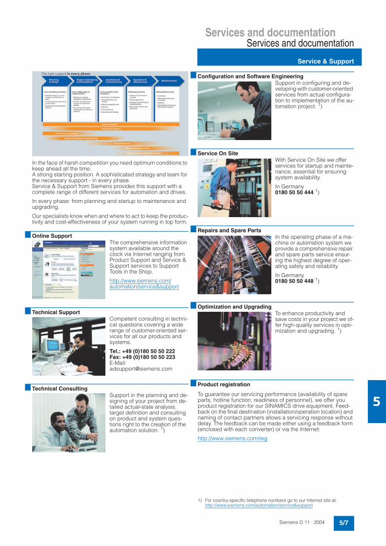
Services and documentationServices and documentation
Service & Support
5/7Siemens D 11 · 2004
5
.I
In the face of harsh competition you need optimum conditions to keep ahead all the time: A strong starting position. A sophisticated strategy and team for the necessary support - in every phase. Service & Support from Siemens provides this support with a complete range of different services for automation and drives.
In every phase: from planning and startup to maintenance and upgrading.
Our specialists know when and where to act to keep the produc-tivity and cost-effectiveness of your system running in top form.
Online SupportThe comprehensive information system available around the clock via Internet ranging from Product Support and Service & Support services to Support Tools in the Shop.
http://www.siemens.com/automation/service&support
Technical SupportCompetent consulting in techni-cal questions covering a wide range of customer-oriented ser-vices for all our products and systems.
Tel.: +49 (0)180 50 50 222Fax: +49 (0)180 50 50 223E-Mail:[email protected]
Technical ConsultingSupport in the planning and de-signing of your project from de-tailed actual-state analysis, target definition and consulting on product and system ques-tions right to the creation of the automation solution. 1)
Configuration and Software EngineeringSupport in configuring and de-veloping with customer-oriented services from actual configura-tion to implementation of the au-tomation project. 1)
Service On SiteWith Service On Site we offer services for startup and mainte-nance, essential for ensuring system availability.
In Germany 0180 50 50 444 1)
Repairs and Spare PartsIn the operating phase of a ma-chine or automation system we provide a comprehensive repair and spare parts service ensur-ing the highest degree of oper-ating safety and reliability.
In Germany 0180 50 50 448 1)
Optimization and UpgradingTo enhance productivity and save costs in your project we of-fer high-quality services in opti-mization and upgrading. 1)
Product registration
To guarantee our servicing performance (availability of spare parts, hotline function, readiness of personnel), we offer you product registration for our SINAMICS drive equipment. Feed-back on the final destination (installation/operation location) and naming of contact partners allows a servicing response without delay. The feedback can be made either using a feedback form (enclosed with each converter) or via the Internet:
http://www.siemens.com/reg
1) For country-specific telephone numbers go to our Internet site at: http://www.siemens.com/automation/service&support

Services and documentationServices and documentation
Documentation
5/8 Siemens D 11 · 2004
5
Overview
The equipment documentation consists of a detailed Instruction Manual with the following sections:• Description• Mounting Instructions• Installation & Start-up Guide• Function description• Maintenance instructions• Spare parts list
as well as equipment-specific dimension drawings, arrange-ment diagrams, circuit diagrams, terminal diagrams.
Documentation in English/German is supplied as standard with the converter:• SINAMICS G130: Documentation on CD-ROM
This documentation is available in English/German.• SINAMICS G150: printed documentation
If one of the languages listed below is required, the corre-sponding order code should be added when ordering the con-verter:
A CD-ROM containing the STARTER commissioning tool is sup-plied as standard with the SINAMICS G130/G150 converters.
Language Order code
English/French D58
English/Spanish D60
English/Italian D80

Siemens D 11 · 2004
6/2 Siemens contacts worldwide
6/3 A&D online services6/3 A&D in the WWW6/3 Product selection using the
interactive catalog6/3 Easy shopping with the A&D Mall
6/4 Subject index
6/5 Order number index
6/6 Terms and conditions of sale and delivery
6/6 Export regulations
Appendix
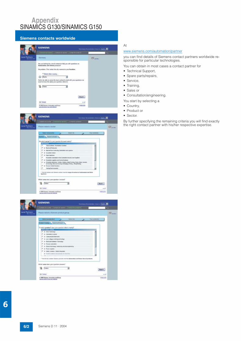
AppendixSINAMICS G130/SINAMICS G150
Siemens contacts worldwide
6/2 Siemens D 11 · 2004
6
At
www.siemens.com/automation/partner
you can find details of Siemens contact partners worldwide re-sponsible for particular technologies.
You can obtain in most cases a contact partner for• Technical Support,• Spare parts/repairs,• Service,• Training,• Sales or• Consultation/engineering.
You start by selecting a• Country,• Product or• Sector.
By further specifying the remaining criteria you will find exactly the right contact partner with his/her respective expertise.

AppendixSINAMICS G130/SINAMICS G150
A&D online services
6/3Siemens D 11 · 2004
6
A&D in the WWWA detailed knowledge of the range of products and services available is essential when planning and configuring automation systems. It goes without saying that this information must always be fully up-to-date.
The Siemens Automation and Drives Group (A&D) has therefore built up a comprehensive range of information in the World Wide Web, which offers quick and easy access to all data required.
Under the address
http://www.siemens.com/automation
you will find everything you need to know about products, sys-tems and services.
Product Selection Using the Interactive CatalogDetailed information together with convenient interactive func-tions:The interactive catalog CA 01 covers more than 80,000 products and thus provides a full summary of the Siemens Automation and Drives product base.
Here you will find everything that you need to solve tasks in the fields of automation, switchgear, installation and drives. All information is linked into a user interface which is easy to work with and intuitive.
After selecting the product of your choice you can order by pressing a button, by fax or by online link.
Information on the interactive catalog can be found in the Inter-net under
http://www.siemens.com/automation/ca01
or on CD-ROM: • Automation & Drives CA 01,
Order No.: E86060-D4001-A110-C2-7600
Easy Shopping with the A&D Mall The A&D Mall is the virtual department store of Siemens AG in the Internet. Here you have access to a huge range of products presented in electronic catalogs in an informative and attractive way.
Data transfer via EDIFACT allows the whole procedure from se-lection through ordering to tracking of the order to be carried out online via the Internet.
Numerous functions are available to support you.
For example, powerful search functions make it easy to find the required products, which can be immediately checked for avail-ability. Customer-specific discounts and preparation of quotes can be carried out online as well as order tracking and tracing.
Please visit the A&D Mall on the Internet under:
http://www.siemens.com/automation/mall

AppendixSINAMICS G130/SINAMICS G150
6/4 Siemens D 11 · 2004
6
Subject indexSection/Page
AAccessories SINAMICS G150 3/11Advanced Operator Panel AOP30 2/26, 3/4, 5/6AOP30 operator panel 2/26, 3/4, 5/6Application
SINAMICS G130 2/2SINAMICS G150 3/2
Application examples 1/9
BBenefit
SINAMICS G130 2/2SINAMICS G150 3/2
Braking modules SINAMICS G130 2/16Braking resistors SINAMICS G130 2/18Braking units
SINAMICS G130 4/15SINAMICS G150 4/22
CCabinet units 3Cable cross-sections SINAMICS G150 4/20Cables SINAMICS G130 2/27Chassis units 2Components in the DC link
SINAMICS G130 2/16, 4/15SINAMICS G150 4/22
Conductor cross-sections SINAMICS G150 4/19Configuring
SINAMICS G130 4/5SINAMICS G150 4/17
Connections SINAMICS G150 4/19Control unit kit SINAMICS G130 2/19Courses 5/3Customer's terminal block(s)
SINAMICS G130 4/8SINAMICS G150 4/18
DDC link components
SINAMICS G130 2/16, 4/15SINAMICS G150 4/22
Degrees of protection SINAMICS G150 4/17Derating data
SINAMICS G130 2/6SINAMICS G150 3/7
Description of options SINAMICS G150 3/16Design
SINAMICS G130 2/2SINAMICS G150 3/3
Dimensioning and selection informationSINAMICS G130 4/5SINAMICS G150 4/17
Dimensioning drives 4/24Dimensions SINAMICS G150 3/10Documentation 5/8Drive converter cabinet units 3Drive converter chassis units 2Drive ES engineering system 4/4
EEarthing SINAMICS G150 4/20EMC information
SINAMICS G130 2/7SINAMICS G150 3/8
EMERGENCY STOP functionsSINAMICS G130 4/4SINAMICS G150 4/17
Engineering information 4
FFunctions
SINAMICS G130 2/4SINAMICS G150 3/4
HHighlights 1/9
Section/PageLLine filters
SINAMICS G130 2/8, 4/14SINAMICS G150 4/21
Line reactorsSINAMICS G130 2/10, 4/14SINAMICS G150 4/21
Line-side componentsSINAMICS G130 2/8, 4/14SINAMICS G150 4/21
MMain applications 1/9Motors 4/25
OOption selection matrix SINAMICS G150 3/14Options SINAMICS G150 3/12Ordering examples SINAMICS G150 3/15Overload capability
SINAMICS G130SINAMICS G150 2/7, 3/8
OverviewSINAMICS 1/6SINAMICS G110 1/10SINAMICS G130 1/12, 2/2SINAMICS G150 1/12, 3/2
PPower Modules SINAMICS G130 2/12Protection functions 2/4, 3/5
SSelection and ordering data
SINAMICS G130 2/8 to 2/27SINAMICS G150 3/9
Selection guides 4/2Selection information
SINAMICS G130 4/5SINAMICS G150 4/17
Service & Support 5/7Services 5Signal cables SINAMICS G130 2/27SINAMICS G110 1/10SINAMICS G130 2SINAMICS G150 3SINAMICS S120 1/9SIZER 4/2SIZER configuration tool 4/2SMC30 sensor module cabinet-mounted 2/25Software functions 2/4, 3/5STARTER 4/3STARTER commissioning software 4/3STARTER drive software 4/3
TTB30 terminal board SINAMICS G130 2/21Technical data
SINAMICS G130 2/5SINAMICS G150 3/6
TM31 terminal module SINAMICS G130 2/23Totally Integrated Automation 1/4Training 5/2Training case 5/6
WWeights SINAMICS G150 3/10

AppendixSINAMICS G130/SINAMICS G150
6/5Siemens D 11 · 2004
6
Order number indexSection/Page
3KL5730-... 2/113KL6130-... 2/113KL6230-... 2/11
3NA3132-6 3/113NA3136-6 3/113NA3240-6 3/113NA3244-6 3/113NA3252 3/113NA3252-6 2/11, 3/113NA3254 3/113NA3352-6 3/113NA3354-6 2/11, 3/113NA3365 3/113NA3365-6 2/11, 3/113NA3372 3/113NA3475 2/11, 3/11
3NE1022-2 3/113NE1224-2 3/113NE1225-2 3/113NE1227-2 3/113NE1230-2 3/113NE1331-2 3/113NE1334-2 2/11, 3/113NE1435-2 2/11, 3/113NE1436-2 3/113NE1438-2 2/11, 3/113NE1447-2 2/11, 3/113NE1448-2 2/11, 3/11
3RT1466-6AP36 2/113RT1476-6AP36 2/11
3WL1110-4BB34-4AN2 2/113WL1210-4BB34-4AN2 2/11
6ES7972-0BA41-0XA0 2/196ES7972-0BB41-0XA0 2/19
6FX8002-1AA01-... 2/26, 2/27
6SL3000-0B... 2/86SL3000-0C... 2/106SL3000-1A... 2/166SL3000-1B... 2/18
6SL3040-0GA00-1AA0 2/196SL3055-0AA00-2TA0 2/216SL3055-0AA00-3AA0 2/236SL3055-0AA00-4... 2/266SL3055-0AA00-5CA0 2/25
6SL3060-4A... 2/27
6SL3070-0AA00-0AG0 4/26SL3072-0AA00-0AG0 4/3
6SL3310-1G... 2/12
6SL3710-1G... 3/9
6SW1700-... 4/4
6ZB2480-0CA00 5/6
E86060-D4001-A100-C1 6/3E86060-D6850-A100-C1-7400 5/2E86060-K6850-A101-B4 5/2E86060-K6899-A101-B4-7600 5/2E86060-P6850-A101-C8 5/2
AppendixSINAMICS G130/SINAMICS G150
6/6 Siemens D 11 · 2004
6
Terms and Conditions of Sale and Delivery
By using this catalog you can acquire hardware and software products described therein from the Siemens AG subject to the following terms. Please note! The scope, the quality and the con-ditions for supplies and services, including software products, by any Siemens entity having a registered office outside of Ger-many, shall be subject exclusively to the General Terms and Conditions of the respective Siemens entity.
for customers with a seat or registered office in the Federal Republic of GermanyThe General Terms of Payment as well as the General Conditionsfor the Supply of Products and Services of the Electrical andElectronics Industry shall apply.For software products, the General License Conditions for Soft-ware Products for Automation and Drives for Customers withSeat or registered Office in Germany shall apply.
for customers with a seat or registered office outside of the Federal Republic of GermanyThe General Terms of Payment as well as the General Conditionsfor Supplies of Siemens, Automation and Drives for Customerswith a Seat or registered Office outside of Germany shall apply.For software products, the General License Conditions for Soft-ware Products for Automation and Drives for Customers withSeat or registered Office outside of Germany shall apply.
GeneralThe prices are in € (Euro) ex works, exclusive packaging.The sales tax (value added tax) is not included in the prices. It shall be debited separately at the respective rate according to the applicable legal regulations.In addition to the prices of products which include silver and/or copper, surcharges may be calculated if the respective limits of the notes are exceeded.Prices are subject to change without prior notice. We will debit the prices valid at the time of delivery. The dimensions are in mm. Illustrations are not binding.Insofar as there are no remarks on the corresponding pages, - especially with regard to data, dimensions and weights given - these are subject to change without prior notice.
Comprehensive Terms and Conditions of Sale and Delivery are available free of charge from your local Siemens business office under the following Order Nos.:• 6ZB5310-0KR30-0BA0
(for customers based in the Federal Republic of Germany)• 6ZB5310-0KS53-0BA0
(for customers based outside of the Federal Republic of Germany)
or download them from the Internet:www.siemens.com/automation/mall (Germany: A&D Mall Online-Help System)
Export regulations
The products listed in this catalog/price list may be subject to European/German and/or US export regulations.Therefore, any export requiring a license is subject to approval by the competent authorities.According to current provisions, the following export regulations must be observed with respect to the products featured in this catalog/price list:
Even without a label or with an “AL: N“ or “ECCN: N“, authoriza-tion may be required due to the final destination and purpose for which the goods are to be used.The deciding factors are the AL or ECCN export authorization indicated on order confirmations, delivery notes and invoices.
Errors excepted and subject to change without prior notice.
Responsible for
Technical content:Siemens AG, A&D LD M PM
General editing:Siemens AG, A&D PT 5, Erlangen,Federal Republic of Germany
Siemens AGAutomation & DrivesLarge DrivesPostfach 474390025 NÜRNBERGFEDERAL REPUBLIC OF GERMANY
Order No.: E86060-K5511-A101-A2Printed in the Federal Republic of Germany KG K 0904 8.0 BD 104 En/P422019
AL Number of the German Export List.Products marked other than “N“ require an export license.In the case of software products, the export des-ignations of the relevant data medium must also be generally adhered to.Goods labeled with an “AL not equal to N“ are subject to a European or German export authori-zation when being exported out of the EU.
ECCN Export Control Classification Number.Products marked other than “N“ are subject to a reexport license to specific countries.In the case of software products, the exportdesignations of the relevant data medium must also be generally adhered to.Goods labeled with an “ECCN not equal to N“ are subject to a US re-export authorization.
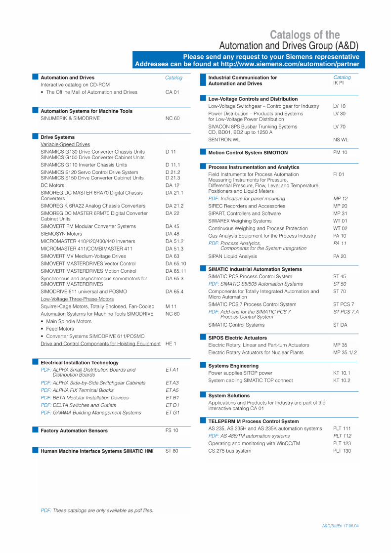
Catalogs of theAutomation and Drives Group (A&D)
Please send any request to your Siemens representativeAddresses can be found at http://www.siemens.com/automation/partner
A&D/3U/En 17.06.04
Automation and Drives CatalogInteractive catalog on CD-ROM
• The Offline Mall of Automation and Drives CA 01
Automation Systems for Machine ToolsSINUMERIK & SIMODRIVE NC 60
Drive SystemsVariable-Speed Drives
SINAMICS G130 Drive Converter Chassis UnitsSINAMICS G150 Drive Converter Cabinet Units
D 11
SINAMICS G110 Inverter Chassis Units D 11.1
SINAMICS S120 Servo Control Drive SystemSINAMICS S150 Drive Converter Cabinet Units
D 21.2D 21.3
DC Motors DA 12
SIMOREG DC MASTER 6RA70 Digital Chassis Converters
DA 21.1
SIMOREG K 6RA22 Analog Chassis Converters DA 21.2
SIMOREG DC MASTER 6RM70 Digital Converter Cabinet Units
DA 22
SIMOVERT PM Modular Converter Systems DA 45
SIEMOSYN Motors DA 48
MICROMASTER 410/420/430/440 Inverters DA 51.2
MICROMASTER 411/COMBIMASTER 411 DA 51.3
SIMOVERT MV Medium-Voltage Drives DA 63
SIMOVERT MASTERDRIVES Vector Control DA 65.10
SIMOVERT MASTERDRIVES Motion Control DA 65.11
Synchronous and asynchronous servomotors for SIMOVERT MASTERDRIVES
DA 65.3
SIMODRIVE 611 universal and POSMO DA 65.4
Low-Voltage Three-Phase-Motors
Squirrel-Cage Motors, Totally Enclosed, Fan-Cooled M 11
Automation Systems for Machine Tools SIMODRIVE NC 60
• Main Spindle Motors
• Feed Motors
• Converter Systems SIMODRIVE 611/POSMO
Drive and Control Components for Hoisting Equipment HE 1
Electrical Installation TechnologyPDF: ALPHA Small Distribution Boards and
Distribution BoardsET A1
PDF: ALPHA Side-by-Side Switchgear Cabinets ET A3
PDF: ALPHA FIX Terminal Blocks ET A5
PDF: BETA Modular Installation Devices ET B1
PDF: DELTA Switches and Outlets ET D1
PDF: GAMMA Building Management Systems ET G1
Factory Automation Sensors FS 10
Human Machine Interface Systems SIMATIC HMI ST 80
PDF: These catalogs are only available as pdf files.
Industrial Communication for Automation and Drives
CatalogIK PI
Low-Voltage Controls and DistributionLow-Voltage Switchgear – Controlgear for Industry LV 10
Power Distribution – Products and Systemsfor Low-Voltage Power Distribution
LV 30
SIVACON 8PS Busbar Trunking Systems CD, BD01, BD2 up to 1250 A
LV 70
SENTRON WL NS WL
Motion Control System SIMOTION PM 10
Process Instrumentation and AnalyticsField Instruments for Process AutomationMeasuring Instruments for Pressure, Differential Pressure, Flow, Level and Temperature, Positioners and Liquid Meters
FI 01
PDF: Indicators for panel mounting MP 12
SIREC Recorders and Accessories MP 20
SIPART, Controllers and Software MP 31
SIWAREX Weighing Systems WT 01
Continuous Weighing and Process Protection WT 02
Gas Analysis Equipment for the Process Industry PA 10
PDF: Process Analytics, Components for the System Integration
PA 11
SIPAN Liquid Analysis PA 20
SIMATIC Industrial Automation SystemsSIMATIC PCS Process Control System ST 45
PDF: SIMATIC S5/505 Automation Systems ST 50
Components for Totally Integrated Automation and Micro Automation
ST 70
SIMATIC PCS 7 Process Control System ST PCS 7
PDF: Add-ons for the SIMATIC PCS 7 Process Control System
ST PCS 7.A
SIMATIC Control Systems ST DA
SIPOS Electric ActuatorsElectric Rotary, Linear and Part-turn Actuators MP 35
Electric Rotary Actuators for Nuclear Plants MP 35.1/.2
Systems EngineeringPower supplies SITOP power KT 10.1
System cabling SIMATIC TOP connect KT 10.2
System SolutionsApplications and Products for Industry are part of the interactive catalog CA 01
TELEPERM M Process Control SystemAS 235, AS 235H and AS 235K automation systems PLT 111
PDF: AS 488/TM automation systems PLT 112
Operating and monitoring with WinCC/TM PLT 123
CS 275 bus system PLT 130

(%&;
!"
! : $ )% <5<81=.2-.9--.:.-)2:79-.>
#?44'!' !4! 7 '-6@@+A++1+5@
(% !# $ # %# % ! % "##" !" $ %% #!%# '$# # "/%/# "$ !% '" # % B $ '