d1.1.1 - realisegrid
TRANSCRIPT

Project no.: 219123
Project acronym
REALISEGRID
Project title:
REseArch, methodoLogIes and technologieS for the effective development of pan-European key GRID infrastructures to support the
achievement of a reliable, competitive and sustainable electricity supply
Instrument: Collaborative project
Thematic priority: ENERGY.2007.7.3.4 Analysis and scenarios of energy infrastructure evolution
Start date of project: 01 September 2008 Duration: 30 months
D1.1.1 Synthetic description of performances and benefits of
undergrounding transmission
Revision: Final version
Submission date: 2009-09-23 Re-submitted: 2009-12-17
Organisation name of lead contractor for this deliverable: Prysmian Powerlink S.r.l.
Dissemination Level
PU Public X PP Restricted to other programme participants (including the Commission Services) RE Restricted to a group specified by the consortium (including the Commission Services) CO Confidential , only for members of the consortium (including the Commission Services)


D1.1.1 Page 3
Deliverable number: D1.1.1 Deliverable title: Synthetic description of performances and benefits of undergrounding transmission Work package: WP1 Performances and costs of innovative grid technologies Lead contractor: Prysmian
Quality Assurance
Status of deliverable Action By Date Verified (WP-leader) Athanase Vafeas, Technofi 2009-12-16 Approved (Coordinator) Gianluigi Migliavacca, ERSE (former: CESI RICERCA) 2009-12-17
Submitted
Author(s) Name Organisation E-mail Ernesto Zaccone Prysmian [email protected]
Abstract The main purpose of this document is to illustrate the available technologies for the underground and submarine electric power transmission as well as their general performances and benefits. Moreover, the technical issues and prospects related to their incorporation in the transmission grid are also considered even though their accurate estimation requires detailed cost-benefit analysis taking into account the local context and the power system. Both HVAC and HVDC underground and submarine cable technologies are dealt with from both the design and installation as well as the reliability points of view. The practical problems related to each technology are highlighted and references to cost data are provided. Finally, some promising cable technologies such as superconducting cables and gas insulated lines are introduced.


D1.1.1 Page 5
TABLE OF CONTENTS Page
ACRONYMS AND DEFINITIONS .............................................................................................. 6
1 EXECUTIVE SUMMARY .................................................................................................... 7
2 INTRODUCTION .................................................................................................................. 9 2.1 Objectives of this deliverable....................................................................................... 9 2.2 Expected outcome ........................................................................................................ 9 2.3 Approach.................................................................................................................... 12
3 HVAC TRANSMISSION CABLE SYSTEM TECHNOLOGIES ...................................... 15 3.1 Self Contained Fluid-Filled Cable Systems ............................................................... 15 3.2 Extruded Dielectric Cables Systems .......................................................................... 16 3.3 Service experience for extruded AC cables ............................................................... 19 3.4 Brief history of transmission power cables evolution................................................ 19
4 HVDC TRANSMISSION CABLE SYSTEM TECHNOLOGIES ...................................... 22 4.1 Mass Impregnated Paper Insulated Cable Systems.................................................... 26 4.2 Extruded Dielectric Cables Systems .......................................................................... 27
5 RELIABILITY OF TRANSMISSION CABLE SYSTEMS................................................ 29 5.1 Reliability assessment ................................................................................................ 29 5.2 System availability ..................................................................................................... 32 5.3 On-site diagnostic, monitoring and maintenance....................................................... 33
6 CHOICE OF THE UNDERGROUND TRANSMISSION SYSTEM.................................. 36 6.1 Function of the transmission network system............................................................ 36 6.2 Rationale for selection of an underground transmission system................................ 36 6.3 Design process of an underground cable connection................................................. 39
7 INSERTION OF AC CABLES INTO THE TRANSMISSION GRID................................ 41
8 INSTALLATION OF UNDERGROUND CABLES ........................................................... 44 8.1 Environmental impact of cables................................................................................. 46 8.2 Electromagnetic fields................................................................................................ 46
9 COSTS OF THE CABLE SYSTEM .................................................................................... 49
10 ADVANTAGES AND DRAWBACKS OF MIXED SOLUTIONS: OHL-UNDERGROUND OR SUBMARINE CABLES ................................................................ 51 10.1 Relevant examples of mixed transmission lines ........................................................ 51 10.2 Advantages and drawbacks of mixed lines ................................................................ 56
11 OTHER INNOVATIVE CABLE TECHNOLOGIES.......................................................... 58 11.1 Superconducting cables.............................................................................................. 58
11.1.1 Design of HTS cables..................................................................................... 58 11.1.2 Characteristics of HTS cables ........................................................................ 59
11.2 Gas Insulated Lines .................................................................................................... 61
12 CONCLUSIONS................................................................................................................... 63
13 REFERENCES...................................................................................................................... 65

D1.1.1 Page 6
ACRONYMS AND DEFINITIONS AC Alternating Current CIGRE International Council on Large Electric Systems CSC Current Source Converter DC Direct Current DTS Distributed Temperature Sensing EHV Extra High Voltage. It is defined as the voltage level for AC systems with a
maximum rated phase to phase voltage lying between 170 kV and 550 kV. EMC Electro-magnetic Compatibility FACTS Flexible Alternating Current Transmission System GIL Gas Insulated Line HTS High Temperature Superconductor (or High Temperature Superconducting cable) HV High Voltage. It is defined as the voltage level for AC systems with a maximum
rated phase to phase voltage lying between 36 kV and 170 kV. HVAC High Voltage Alternating Current HVDC High Voltage Direct Current. HVDC systems are defined as DC systems with a
voltage higher than 100 kV. IEC International Electric Commission IGBT Insulated Gate Bipolar Transistors LCC Line Commutated Converter MI Mass Impregnated N2 Nitrogen OHL Overhead Line PD Partial discharges PST Phase Shifting Transformer RTTR Real Time Thermal Rating SCFF Self Contained Fluid-Filled SCFF-PPL Self Contained Fluid-Filled - Paper Polypropylene Laminated SF6 Sulfur Hexafluorid U Rated AC phase to phase voltage Uo Rated AC phase to ground voltage Um Maximum rated AC phase to phase voltage VSC Voltage Source Converter XLPE Cross Linked Polyethylene Insulation

D1.1.1 Page 7
1 EXECUTIVE SUMMARY The main purpose of this document is to describe the available technologies for underground and submarine electric power transmission, as well as their performances and benefits. Moreover, the technical issues and prospects related to their incorporation in the transmission grid are also addressed. The development and rationalization of High Voltage (HV) and Extra High Voltage (EHV) transmission grids in European countries, as well as the need for an extension of interconnections, will lead to an increased use of underground and submarine cable connections. Submarine cables are suitable for the interconnections between regions across sea with islands, and for the connection of off-shore plants (either wind farms or oil platforms). Differently from land connections, cables are the only technically feasible option for the realization or implementation of these submarine projects. Due to economic reasons and simplicity of construction, overhead lines are traditionally preferred by operators for land connections. However, as overhead lines have a very high visual impact on the landscape, today it is more and more difficult to find suitable corridors for their realization, especially in the most densely populated regions of Europe. From this point of view, the underground cable technology represents an alternative and challenging solution, which allows solving complicated situations and overcoming difficult and long authorization procedures. In recent years, there has been a significant amount of investment in research and development aimed at reducing the cost differentials between overhead lines and underground cables. Underground transmission technology, based on the use of oil-filled cables, has been available for decades. This technology was mainly implemented in cities, where the presence of existing infrastructures and services implies very high construction costs. Although the reliability of these cables was very high, the construction was complicated and required high level of workmanship’s skills; furthermore, the presence of oil under pressure involved some maintenance aspects and environmental concerns. Thanks to the efforts of the industry in the recent years, a commercial solid dielectric transmission cable, having the XLPE (Cross Linked Polyethylene) insulation, is now available. This technology is simple, and requires a low level of workmanship and maintenance, especially due to the fact that prefabricated accessories (joints and terminations) are available. In the last 10 years, a significant increase of underground transmission circuits, up to the voltage of 400 kV, has been observed in Europe. The availability of continuous monitoring and diagnostic systems contributes to make modern underground transmission systems highly reliable, and capable of satisfying operators’ expectations in terms of safety of power supply and behaviour under severe environmental conditions. Underground cables systems are very versatile and thus can be used for the realization of the most difficult cabling solutions of the transmission grid. The conductors of these cables are generally much larger than those of the equivalent overhead lines, thus resulting in lower transmission losses.

D1.1.1 Page 8
Due to their high capacitance, AC (Alternating Current) cables produce a reactive power load that is proportional to the length of the circuit and to the voltage; for this reason, an inductive reactive compensation (shunt reactor) is necessary for very long circuits. Another important aspect of underground cables is that the EMF (Electro Magnetic Field) impact is very reduced. High voltage cables have an individual earthed screen on each core and the electric field is practically negligible, eliminating then the risk of electrocution. Although the magnetic field generated in proximity of underground cable circuits is not negligible, in certain circumstances, where cables are very close to populated areas, it is possible to screen the circuits in order to reduce the magnetic field to the requested limits fixed by laws. High Voltage Direct Current (HVDC) cables are the appropriate solution for very long submarine connections. The absence of reactive power does not give any limitation to the length of the circuit, which may reach several hundreds of kilometres; moreover, the longer the circuit is, the lower the economic influence of the AC-DC conversion stations and the higher the convenience of this choice with respect to other power transmission technologies. Thanks to the new technologies available today for converters stations and cables, HVDC transmission systems may represent a valid solution for important very long submarine or land interconnections that may be necessary in the near future to reinforce the European power grid. Other transmission systems cable technologies will be available in the future, such as Superconducting cables and Gas Insulated Lines (GILs). Superconducting cables are under development and some very specific experimental short length projects have already been implemented. This kind of cable is suitable for the transmission of large amount of power by a single circuit, and may find an application for the replacement or the retrofitting of obsolete circuits maintaining the same route or right of way. Today, the complexity of the systems used to maintain the very low temperature (cryogenic) and the reduced experience limit the adoption of superconducting cables to niche applications. Some pilot projects are ongoing in different countries around the world to validate the technology and to monitor its performances. Another innovative transmission technology is represented by the Gas Insulated Lines. These lines are very similar to pipelines in which the inner conductors are insulated by a mixture of sulphur hexafluoride (SF6) and nitrogen (N2) gas under pressure. These lines can transport very high power, i.e. 3 GW, but they need very large infrastructures. As of today, the service experience of GIL is limited to some short connections implemented inside substations and installed either above ground or in tunnels. Today, the industry is offering a wide range of possibilities for the improvement of the transmission grid; the users will have to select the most appropriate technologies for their specific cases based on the technical performance and taking into account both the environmental and economic aspects. The selection of the most appropriate technology is not simple and may vary depending on the structure of the grid: general solutions cannot be applied to all cases. Detailed cost benefit analysis based on simulation of the individual network through power load flow studies are necessary.

D1.1.1 Page 9
2 INTRODUCTION 2.1 Objectives of this deliverable The aim of this deliverable is to present the state-of-the-art underground transmission technologies available today for the implementation and extension of the future European transmission grid, together with their performances and benefits. Moreover, the technical issues and prospects related to their incorporation in the transmission grid are also addressed. The case of High Voltage Alternating Current (HVAC) and High Voltage Direct Current (HVDC) systems as well as promising cable technologies are considered. The evolution of power underground cables is a slow process: a very high reliability is required, and, before being adopted on a commercial basis, a new type of cable shall pass through a heavy development and prequalification process requiring years or decades before being adopted with a sufficient level of confidence. Today, extruded insulation cables offer a solution for underground HVAC transmission connections: the availability of prefabricated joints and terminations and a complete monitoring system allow reaching a high level of reliability and availability of the line. Compared to traditional fluid-filled cables, the adoption of extruded cable makes the cabling system simpler and more economic. These advantages will allow using extruded cables for connections in larger areas, that may include not only urban areas (as it was the case for traditional underground cables), but also suburban sites. Underground AC (Alternating Current) transmission cables have different characteristics from equivalent overhead lines; hence, a detailed study of the system is necessary before their implementation. With the availability of advanced and more economic conversion stations, HVDC connections will also be a future possible alternative for the realization of both underground and submarine long connections. This technology is particularly suitable for the realization of asynchronous interconnections between different regions in case of scarce compatibility of the electric systems, and for the connection of remote power generation plants (e.g. off-shore wind generators). Different technologies are available, that may be chosen as a function of the voltage and power to be transmitted. The HVDC technology offers a number of good performances in terms of load transmission management and, in some circumstances, may represent the optimal solution. The present document briefly deals also with new transmission technologies, based on superconducting cables and Gas Insulated Lines (GILs). These technologies are rather innovative. As of today, there is limited implementation experience and they are used for very specific applications. Further development is however needed before a more extensive deployment. 2.2 Expected outcome This document provides an indicative evaluation of the performances and benefits of underground cables. As a matter of fact, the design of a transmission line is carried out based on complex technical studies and economic evaluations. These studies are typically based on specific projects, with detailed input information. Without this information, it is possible to give only general technical indications and principles for the selection of the suitable transmission system.

D1.1.1 Page 10
Although only less than 5 % of the High Voltage (HV) and Extra High Voltage (EHV) networks of the European countries is represented by underground cables, their use will undoubtly increase in the next years. The extension and reinforcement of the transmission grid is mandatory in order to guarantee security of supply: the adoption of underground cables will allow solving a number of difficulties, such as the concession of authorizations in a reasonable period of time, the opposition of local communities, the cost of land occupation, and other conflict of public or private interest. The service experience gained so far with the adoption of the extruded insulation EHV cable systems demonstrates that this technology is now mature enough to be used on a larger scale in a safe and efficient transmission grid. The impact of a large use of EHV cables on the grid shall be evaluated on a case by case basis. The main features and typologies of underground and submarine cables for AC transmission are described in Chapter 3 and reference is made to extruded insulation cables, which find an extended application today. The history of underground cables and references to some of the most important applications are introduced as well. Characteristics, typology and references to the most relevant realized HVDC cables projects are also provided in Chapter 4. One of the major concerns of the Transmission Systems Operators (TSOs) is to guarantee a high level of reliability of the transmission network. This is an extremely important aspect that may have an impact on the social community involving a high number of people. Hence, the approach used to guarantee an acceptable reliability level for underground cables is described in Chapter 5. This approach involves the requirements of the standards and the recommended monitoring and maintenance procedures. Modern cables systems may be equipped with a full on-line monitoring that prevents unexpected premature failures. Due to the high capacitance of insulated cables, HVDC transmission may be a solution for the realization of very long connections. An indicative range of convenience for the adoption of HVAC or HVDC underground or submarine cable connection is also reported in Chapter 6. Underground cables have line and load parameters that are very different from those ones of overhead lines (OHLs). For this reason, the insertion of insulated cables in the existing transmission system requires complex evaluations. Several kinds of connections or insertions of cables in the transmission grid are possible having each different peculiarities. These are detailed in Chapter 7. Traditionally, underground cables have been installed inside cities, with a number of difficulties related to the existence of other services, crossing, and the impact on the circulation of vehicles. More recently, some important underground connections have been realized in suburban as well as in country areas, with different type of problems. Possible methods to reduce the impact on the environment are described as well in Chapter 8. The evaluation of the costs of an underground cable system cannot be made a priori: one of the major cost items is represented by the costs of civil works (such as trenching and other construction works) that are strongly dependent on the local situation. In order to avoid incurring in big misunderstanding that may influence the decision to be taken, the cost of underground or submarine cable connections is to be evaluated on the basis of the knowledge of all the necessary information related to the specific project as explained in Chapter 9. With this caveat in mind, some cost ranges for HVAC OHL and underground solutions are provided based on a collective exercise performed jointly with REALISEGRID partners including TSOs.

D1.1.1 Page 11
Chapter 10 describes the main features and applications of using mixed transmission solutions based on the combination of overhead lines and underground cables (in the so-called ‘siphon’ scheme). A summary of the main techno-economic and environmental characteristics of HVAC and HVDC overhead and underground solutions is also part of Chapter 10. Chapter 11 presents other underground innovative transmission technologies: High Temperature Superconducting (HTS) cables and Gas Insulated Lines (GILs). Although, at present, these technologies are used for limited special applications, they may be subject to further development and find a more extended application in the future. Finally, Chapter 12 recaps the main outcomes of the present report and tracks the way forward. This document looks at the future of underground transmission - from developments on the verge of commercial application to those ones further out in the research frontier - and the achievements and benefits that will be possible thanks to the adoption of the new available technologies. The integration of underground cables in the transmission grid will result in smarter systems, which will allow working in safer and optimized conditions.

D1.1.1 Page 12
2.3 Approach The need for a better exploitation of the available world energy resources will require an efficient transmission grid. Today one of the major objectives of the most advanced countries is the reduction of the greenhouse gas effect, due to CO2 emissions, that is to be mainly achieved through the increased production of energy from renewable energy sources (RES). For a number of reasons, generation plants are generally located in remote areas that are far from energy demand located mainly in urbanized and industrialized areas, where energy is really necessary. The availability of an extended and optimized transmission grid is of paramount importance for the power transfer from the production sites up to the utilization sites. The extension of the transmission grid or the building of new infrastructures is generally characterized by a strong impact on the environment and by very long authorization procedures. In certain cases, the opposition of the population or of local authorities hampers the implementation of the project. The major reasons for these difficulties are represented by land depreciation due to the occupation of the soil and by the visual impact of the transmission line, which may have a negative influence on the existing and new buildings market. Underground transmission cannot compete with overhead transmission in many scenarios, simply because the dielectric system is much more complex and expensive, and the cost of the installation can be several times the cost of the overhead system. The suburban environment is another matter altogether. This will become a promising area for new installations of underground transmission. Communities often prefer to install underground transmission lines rather than overhead lines in their neighborhoods, because they believe that overhead lines could devalue their property or may have detrimental environmental effects. Aesthetic issues, environmental concerns, weather-related outages, and the increasing cost of rights-of-way will be factors in the future that may make underground cables an attractive alternative to overhead lines. It is expected that this situation of public pressure will not decrease, while the cost difference between overhead and underground transmission links continues to narrow. The legislations of certain countries have been monitoring the life-cycle costs of the two options and it appears that underground transmission lines might become a mandatory requirement “by law” for several future transmission constructions. This trend is predicted to continue around the world, and particularly in highly populated countries, such as European countries. One point must be clear: simple cost ratios of underground to overhead options should never be used. Each potential scenario must be independently evaluated. This document looks at the future of underground transmission - from developments on the verge of commercial application to those further out in the research frontier - and the achievements and benefits that will be possible thanks to the adoption of the new available technologies. The integration of underground cables in the transmission grid will result in smart systems, which will allow working in safe and optimized conditions. The approach followed to that purpose is based on the compilation of existing technical and scientific literature, information from REALISEGRID partners with a substantial contribution from Prysmian.

D1.1.1 Page 13
In order to evaluate the efficiency of a transmission line, a very detailed study of the load flow has to be carried out. In fact, when building a new line, the status of the grid configuration taking into account the new connection should be evaluated. In some circumstances, it may happen that the new constructed line remains under utilized and cannot bring the expected benefits in terms of power transfer. Today, by using the most modern available technologies based on FACTS (Flexible AC Transmission System), it is possible to optimize the AC transmission and to tune the load flow in order to reach the full utilization of the transmission line. Similar benefits can be achieved by using HVDC transmission, which is particularly suitable for long interconnections, in particular by using submarine cables. Although a detailed analysis of the characteristics of these new transmission technologies (which are well described in the technical literature and are addressed within REALISEGRID project Deliverable D1.2.1) is not within the scope of the present document, it is clear that a great improvement in the load flow management and in the utilization of the line can be achieved thanks to these technologies. Under these conditions, real time thermal rating (RTTR) monitoring of underground cables systems, together with load tuning, will offer an excellent opportunity for a full utilization of transmission lines in economic and safe conditions. Today, the simpler technology of extruded insulation cable systems, in terms of production, installation, and maintenance, offers a lower total cost of ownership and provides then a wider offer of applications for the realization of new underground connections. When considering a new cable system, the following design parameters and aspects shall be taken into consideration:
• Load to be transmitted; the impact of the reactive power produced by the cable on the network; the load sharing in case of parallel with other lines; the voltage stability; the fault current.
• Economic evaluation and verification of the planned load flow; contingency and fault of the line and possible alternative solutions.
• Transient voltage stability and switching over-voltages (circuit switching operations, system auto-restoration, resonance); lightning over-voltages; need for voltage surge limiters; evaluation of the behavior under fault and emergency conditions.
By applying the theory of the transmission lines, it is possible to reach the conclusion that the characteristics of the cable systems, in general, may offer some benefits in terms of voltage stability of the network, especially in heavy load conditions1.
1 Although no detailed study or literature is known about the impact of cables on the grid stability. It is possible to say in principle that the steady state stability limit is improved in the area where long HVAC cable are applied. When considering the maximum stability limit length L for a given active power transfer P, this is given by (being V and V1 the voltage at the extremities of the line )
ϑsin1 ⋅⋅⋅
=PXVVL
Due to the usually low value of direct reactance X, the L value of a cable may be 2-3 times greater than for overhead lines. Nodes are therefore more electrical tightened each other if connected with cables and overall they may improve area stability following faults or loss of generation in the system reducing oscillations.

D1.1.1 Page 14
For very long applications of HVAC cable lines, a reactive compensation of the line may be required for the following major reasons:
• To compensate the capacitive current absorbed by the cable that may reduce the cable current carrying capacity.
• To reduce the voltage increase (Ferranti effect2) in the no load conditions, especially in weakly meshed grids.
• To facilitate the black starting of remote low power generators. The reactive inductive compensation (shunt reactors) improves the efficiency and flexibility of the connection in most of the load conditions; generally shunt reactors are installed inside substations at the extremity of the connection. Finally, it is worth mentioning the close interrelation between the present REALISEGRID Deliverable D1.1.1 and REALISEGRID Deliverable D1.2.1 (focused on FACTS and HVDC technologies), Deliverable D1.4.1 (concerning innovative transmission technologies) and D1.1.2 (focused on real time thermal rating for cables). A close interaction with other REALISEGRID partners and stakeholders has been key to validate the present work.
Further advantages may be underlined in an EMC area, in particular for fast and very fast transient phenomena, i.e. switching and lightning. The low high-frequency surge impedance acts as damper of surge overvoltages propagating in the circuit. For very long cables, the damping effect is so large that it allows the planner to prevent surge arresters installations. However, large amount of cables must introduce drawbacks as they may create favorable conditions to sustained power frequency overvoltages following switching operations, due to parallel and/or series resonance phenomena. This may be likely to occur the weaker the Power System is. 2 The Ferranti effect is the rise in voltage that may occur at the receiving end of a long transmission line when operating at a reduced or zero load. The Ferranti effect is a function of the line capacitance or susceptance; for this reason it may be more pronounced in underground cables than in overhead lines.

D1.1.1 Page 15
3 HVAC TRANSMISSION CABLE SYSTEM TECHNOLOGIES The HVAC underground transmission technology finds its application in urban and suburban densely populated areas, in submarine connections and, in general, where the implementation of overhead lines is difficult or impossible. HVAC cables are in general characterized by a significant power transmission capacity, thus introducing unacceptable quantities of reactive power into the system that needs to be compensated by the utilisation of shunt reactors. The generated reactive power is proportional to the length and the square of the voltage of the cable connection: the higher the voltage, the shorter is the maximum length of the connection that may be realized without reactive compensation. The admissible amount of reactive power generated by the cable is dependent on the power of the system where the cable line is introduced. For instance, a 400 kV cable line longer than 20-25 km may need reactive compensation, while a 150 kV cable line in the same system may require reactive compensation if it is longer than 100 km. Being underground cables embedded and thermally insulated by the soil, the conductor size shall be larger than that one of the corresponding overhead line, thus producing reduced transmission losses. The cable systems suitable for HVAC underground transmission can be distinguished in the two major categories described in the following sections. 3.1 Self Contained Fluid-Filled Cable Systems Self contained fluid-filled (SCFF) cables have been used for underground and submarine power transmission for at least 70 years. Since 1924, this kind of cable has been used for some very important connections, mainly in cities and for some submarine crossways. The insulation of a SCFF cable is composed by multi-layers of pure cellulose paper tapes impregnated by fluid oil under pressure. More recently, pure cellulose paper tapes have been replaced by composite tapes, which are a sandwich of cellulose and polypropylene film, named paper–polypropylene laminated (PPL) tape that offers some improved properties in terms of capability. SCFF cables have an excellent record of reliability in service and for many years have represented the only solution for difficult connections, whose realization was impossible with overhead lines. SCFF cables are mainly composed by the oil channel, the conductor, the oil impregnated paper, maintained under pressure by the oil in the channel, and impervious lead or aluminium metallic sheath, and an overall protective sheath. In addition, submarine cables are also armored in order to improve their mechanical performances. Figure 3.1 provides an example of a SCFF cable. Oil reservoirs shall be placed at the terminations and, for long connections, also along the route in order to maintain the suitable oil pressure inside the cable; for long submarine lines, a pressurizing oil pumping plant is necessary at one or both ends.

D1.1.1 Page 16
Figure 3.1: Self Contained Fluid-Filled (SCFF) cable sample
The presence of the dielectric liquid and reservoirs and the necessity to maintain the cable under pressure throughout its whole life require a permanent monitoring: this is a disadvantage of the SCFF cable system. Designs of SCFF cables at 1100 kV voltage for power transmission of 3 to 7 GVA have to successfully passed long preliminary tests and qualifications for the installation, directly buried, in ducts, and in tunnels. Although the technology at this extremely high voltage level is available today, commercial applications of (both underground and submarine) SCFF cable systems are for 420 and 550 kV voltages for power transmission of 1 to 1.5 GVA per circuit, with a copper conductor of 2500 mm2. 3.2 Extruded Dielectric Cables Systems During the last 3 decades, important evolutions in process technology and in materials have made possible the adoption of extruded insulation for transmission cables at 150 kV voltages and, in the last 10 years, up to 420 kV and 550 kV voltages. Extruded insulated cables are mainly composed by the copper or aluminum conductor, the extruded polymeric conductor screen, the insulation (a layer of extruded cross linked polyethylene (XLPE)), the extruded insulation screen, the metallic screen and the outer sheath. Figure 3.2 shows a sample of extruded XLPE cable.

D1.1.1 Page 17
Figure 3.2: Extruded XLPE cable sample
The absence of a hydraulic circuit, lower dielectric losses, together with a more simplified construction process of the system due to the availability of prefabricated accessories, make extruded insulation cables systems more attractive than SCFF ones also from the point of view of the total cost of ownership.
Within the REALISEGRID project, focus will be on AC extruded XLPE cable systems, since this type of cables is considered as the most suitable technology for the future application and integration in the extended, smart transmission grid. Extruded cables are preferred to SCFF cables mainly due to:
the absence of the hydraulic circuit necessary to maintain the oil pressure the lower maintenance the lower voltage depending losses due to lower dielectric power factor the availability of prefabricated accessories, which strongly simplify and reduce
construction works. These factors influence the global cost of ownership (investment, operation and maintenance) of the cable transmission system. In particular, the advantage of using prefabricated accessories for extruded XLPE cables is mainly related to the higher quality and reliability offered to the completed cable system. Prefabricated accessories are manufactured in a very controlled environment at the factory level and 100% routine tested before being fitted on the cable. Moreover, with this kind of accessories the workmanship is limited to the preparation of the cable ends to be jointed or terminated and, then, to the installation of the accessories; hence, the risk of human error during the preparation of cable accessories is strongly reduced. The final test on the complete connection before entrance into service aims at identifying any eventual residual human errors during installation. Table 3.1 recaps the main features of SCFF and XLPE cables for AC transmission: a relative scale is used for the comparison of the two types of AC cables.

D1.1.1 Page 18
Table 3.1: Comparison between SCFF and XLPE cables
SCFF XLPE Maturity of technology ■■■ ■■ Reliability ■■■ ■■ Equipment costs ■■■ ■■ Installation costs ■■■ ■■ Engineering costs ■■■ ■■ Operation and Maintenance costs ■■■ ■ Dielectric losses ■■■ ■ Environmental impact ■■ ■
Relative scale: ■ — Low; ■■ — Medium; ■■■ — High Figure 3.3 shows the prefabricated joint installed on the cable.
Figure 3.3: Prefabricated joint for EHV extruded XLPE cable
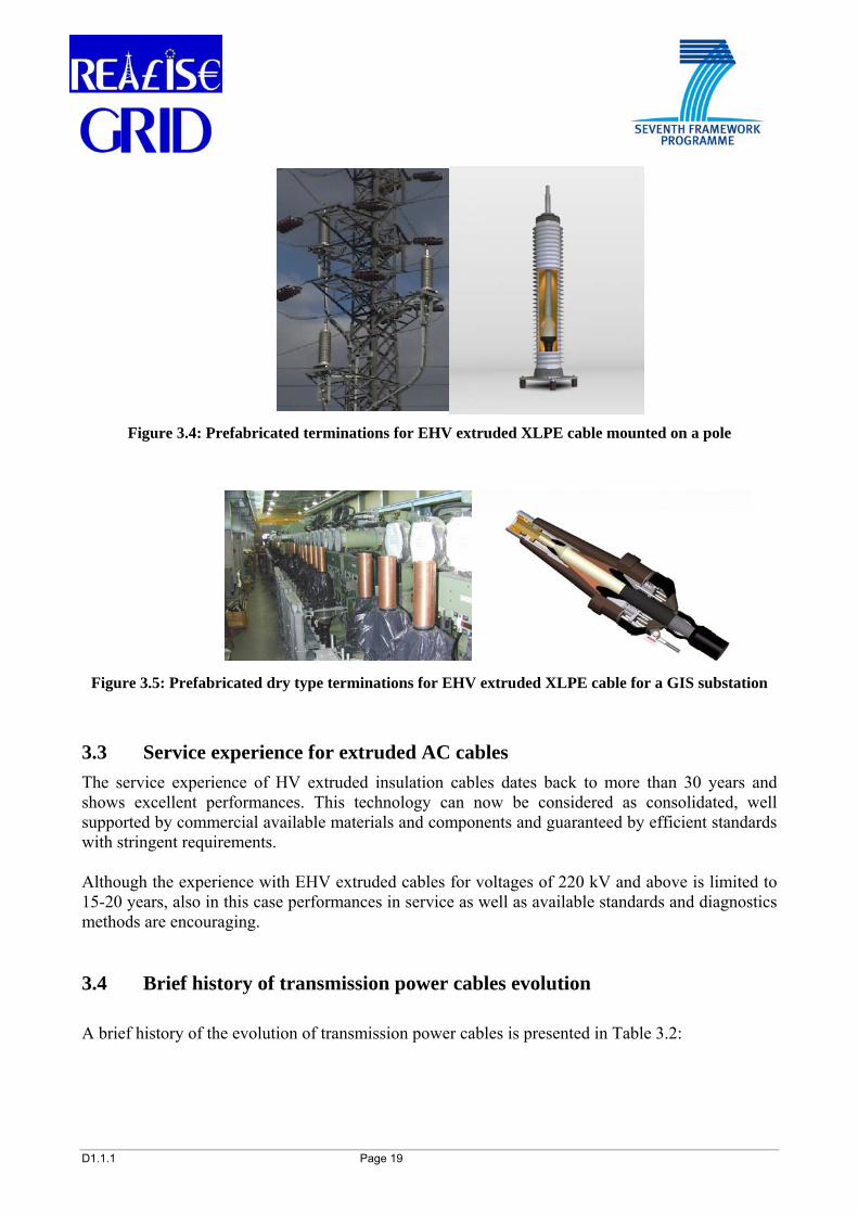
Prefabricated terminations for outdoor and indoor applications are available as well. Figure 3.4 shows outdoor terminations with a synthetic anti-explosion insulator mounted on the final pole of an overhead line. Figure 3.5 shows an indoor termination mounted on a gas insulated switchgear (GIS).
D1.1.1 Page 19
Figure 3.4: Prefabricated terminations for EHV extruded XLPE cable mounted on a pole
Figure 3.5: Prefabricated dry type terminations for EHV extruded XLPE cable for a GIS substation
3.3 Service experience for extruded AC cables The service experience of HV extruded insulation cables dates back to more than 30 years and shows excellent performances. This technology can now be considered as consolidated, well supported by commercial available materials and components and guaranteed by efficient standards with stringent requirements. Although the experience with EHV extruded cables for voltages of 220 kV and above is limited to 15-20 years, also in this case performances in service as well as available standards and diagnostics methods are encouraging. 3.4 Brief history of transmission power cables evolution A brief history of the evolution of transmission power cables is presented in Table 3.2:

D1.1.1 Page 20
Table 3.2: Chronicle of the power cables evolution
Year Phase to Phase Voltage-kV Type of cable 1890 10 First AC mass impregnated cable – Ferranti 1913 33 Mass impregnated cable 1924 132 SCFF cable 1936 220 SCFF cable 1947 20 Extruded Thermoplastic Polyethylene - PE cable 1952 400 SCFF cable 1960 20 Extruded Cross Linked Polyethylene – XLPE Cable 1966 138 Extruded Cross Linked Polyethylene – XLPE Cable 1974 500 SCFF cable 1979 275 Extruded Cross Linked Polyethylene – XLPE Cable 1980 1000 SCFF cable 1986 420 Extruded Cross Linked Polyethylene – XLPE Cable 1988 550 Extruded Cross Linked Polyethylene – XLPE Cable
During the 90’s the adoption of extruded EHV cables up to 550 kV voltages found application in some very important circuits of many countries. These major circuits are well described in the technical literature mentioned in the references (Chapter 13). In particular, CIGRE Technical Brochure 338 [18] provides historical statistics on underground cables in power transmission systems and shows that the percentage of underground transmission is strongly variable among countries, and that is decreasing at the higher voltages. Typical average percentages are:
for voltages up to 150 kV: 7% for voltages ranging from 300 kV to 500 kV: 0.5%.
These percentages are expected to increase with the adoption of extruded insulation cables in the next years. Table 3.3 and Table 3.4 are a summary of the most important HV and EHV underground cable connections, ever realized for land and submarine application.

D1.1.1 Page 21
Table 3.3: Some relevant EHV land AC cable projects of recent realization ([29])
Voltage Conductor Country Project name
kV mm2 material Insulation
N° of circuits
and length km
Installation Year
Denmark Metropolitan power project
400 1600 Cu XLPE 1 x 12 1 x 9
Direct buried 1997
Germany Berlin diagonal 380 1600 Cu XLPE 2 x 6.3 Tunnel 1998 Denmark Metropolitan
power project 400 1600 Cu XLPE 1 x 12 Direct buried 1999
Japan Shinkeiy-Toyosu 500 2500 Cu XLPE 2 x 39.8 Tunnel –bridge 2000 Germany Berlin diagonal 380 1600 Cu XLPE 2 x 5.3 Tunnel 2000 S. Korea Sinbupoung-
Seoinchon 345 2000 Cu SCFF-PPL 3 x 17 Tunnel 2002
S. Korea Nampusan-Bukpusan
345 2000 Cu SCFF-PPL 1 x 22 Tunnel 2003
Denmark Aarhus-Aalborg 400 1200 Al XLPE 1 x 2.5 1 x 4.5 1 x 7.5
Direct buried 2004
Spain Barajas Airport 400 2500 Cu XLPE 2 x 12.8 Tunnel 2004 UK Nunthorpe-Newby 400 2000 Cu SCFF-PPL 2 x 5,7 Direct buried 2004 UK Elstree-St. Johns
Wood 400 2500 Cu XLPE 1 x 20 Tunnel 2005
Netherlands NieuweWaterweg 380 1600 Cu XLPE 2 x 2.3 Direct buried 2005 Austria Wienstrom 380 1200 Cu XLPE 2 x 5.2 Direct buried 2005 Italy Turbigo-Rho 380 2000 Cu XLPE 2 x 8.4 Direct buried 2006
Table 3.4 – Some major HV-EHV submarine AC cable projects ([7])
Voltage Conductor
Country Project name kV mm2 material
Insulation N° of
circuits and length
km
Water depth m Year
Spain Mallorca-Menorca 132 500 Cu SCFF 1 x 42 90 1973 Canada Vancouver isl. 525 1600 Cu SCFF 1 x 39 400 1984 USA Long Island Sound 345 2000 Cu SCFF 1 x13 35 1991 Philippines Leyete – Cebu 230 630 Cu SCFF 1 x 33 280 1995 Malaysia Penang isl. 275 800 Cu SCFF 2 x 14 20 1996 Spain Spain - Morocco 400 800 Cu SCFF 1 x 26 630 1997 Egypt Gulf of Aqaba 400 1000 Cu SCFF 1 x 13 840 1997 UK Isle of Man 90 3x300 Cu XLPE 1 x 10⁵ 40 2000 USA Galveston Isl. 138 3x630 Cu XLPE 1 x 5 15 2001 Denmark Horns Rev wind farm 150 3 x630 Al XLPE 1 x 21 20 2002 Denmark Seas Roedsand wind farm 132 3x760 Cu XLPE 1 x 22 20 2003 Italy Sardinia – Corsica isl. 150 3x400 Cu XLPE 1 x 15 75 2005 Norway Gossen isl. 400 1600 Cu XLPE 1x3.2 200 2007

D1.1.1 Page 22
4 HVDC TRANSMISSION CABLE SYSTEM TECHNOLOGIES Nowadays, the HVDC transmission cable technology is widely used mainly for the realization of long submarine interconnections and for few land applications. In the near future extensions of the land applications are expected thanks to the adoption of new technologies based on the advanced AC/DC converter stations of new concept, and on some evolutions on the characteristics of the HVDC cables. The HVDC transmission needs AC-DC and DC-AC conversion stations at the extremities of the HVDC link and becomes competitive for very long connections. HVDC transmission offers some key advantages with respect to HVAC transmission, which may be summarized as follows:
• The absence of reactive power does not impose any limit to the length of the connection • A lower number of cables is necessary for the transmission of the same power • Transmission losses are lower • Different grids can be connected independently of the frequency and synchronism
(interconnection of asynchronous networks) • Grid perturbations are not transferred, thus reducing possible risk of extended blackouts • The load flow is maintained under control.
A more in-depth analysis of the characteristics and advantages of the HVDC transmission systems is in the scope of the REALISEGRID Deliverable D1.2.1. HVDC connections are very reliable and, to our knowledge, no failures of the intrinsic dielectric have been noticed so far. HVDC cables are mainly used for submarine applications. Table 4.1 lists the major HVDC submarine connections currently in service. All submarine cable links have a portion of circuit installed underground in the land covering the part of the route between the shore and the station. The length of this land portion may range between a few hundred meters and several kilometers, depending on the local displacement of the stations. Although very few pure land HVDC cable connections are known as of today, some relevant projects (like for instance those ones in Europe concerning cross-border France-Spain and France-Italy interconnections and the link in the south of Sweden) are in progress and others may be realized in the near future.
D1.1.1 Page 23
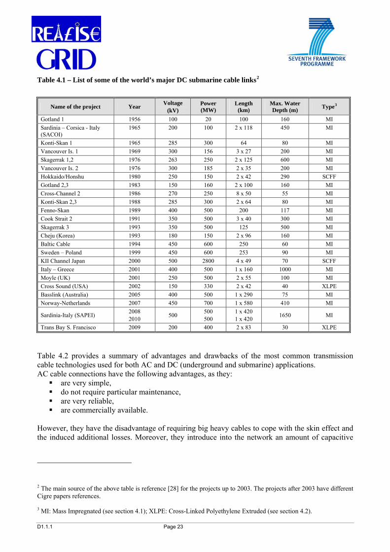
Table 4.1 – List of some of the world’s major DC submarine cable links2
Name of the project Year Voltage (kV)
Power (MW)
Length (km)
Max. Water Depth (m) Type3
Gotland 1 1956 100 20 100 160 MI Sardinia – Corsica - Italy (SACOI)
1965 200 100 2 x 118 450 MI
Konti-Skan 1 1965 285 300 64 80 MI Vancouver Is. 1 1969 300 156 3 x 27 200 MI Skagerrak 1,2 1976 263 250 2 x 125 600 MI Vancouver Is. 2 1976 300 185 2 x 35 200 MI Hokkaido/Honshu 1980 250 150 2 x 42 290 SCFF Gotland 2,3 1983 150 160 2 x 100 160 MI Cross-Channel 2 1986 270 250 8 x 50 55 MI Konti-Skan 2,3 1988 285 300 2 x 64 80 MI Fenno-Skan 1989 400 500 200 117 MI Cook Strait 2 1991 350 500 3 x 40 300 MI Skagerrak 3 1993 350 500 125 500 MI Cheju (Korea) 1993 180 150 2 x 96 160 MI Baltic Cable 1994 450 600 250 60 MI Sweden – Poland 1999 450 600 253 90 MI KII Channel Japan 2000 500 2800 4 x 49 70 SCFF Italy – Greece 2001 400 500 1 x 160 1000 MI Moyle (UK) 2001 250 500 2 x 55 100 MI Cross Sound (USA) 2002 150 330 2 x 42 40 XLPE Basslink (Australia) 2005 400 500 1 x 290 75 MI Norway-Netherlands 2007 450 700 1 x 580 410 MI
Sardinia-Italy (SAPEI) 2008 2010 500 500
500 1 x 420 1 x 420 1650 MI
Trans Bay S. Francisco 2009 200 400 2 x 83 30 XLPE
Table 4.2 provides a summary of advantages and drawbacks of the most common transmission cable technologies used for both AC and DC (underground and submarine) applications. AC cable connections have the following advantages, as they:
are very simple, do not require particular maintenance, are very reliable, are commercially available.
However, they have the disadvantage of requiring big heavy cables to cope with the skin effect and the induced additional losses. Moreover, they introduce into the network an amount of capacitive
2 The main source of the above table is reference [28] for the projects up to 2003. The projects after 2003 have different Cigre papers references. 3 MI: Mass Impregnated (see section 4.1); XLPE: Cross-Linked Polyethylene Extruded (see section 4.2).
D1.1.1 Page 24
reactive power that is a function of link length and voltage; when the capacitive reactive power is higher than the one supported by the system, inductive reactive compensation is necessary. Finally, independently of the type of connection (i.e. cable or overhead lines), AC connections are rigid since they do not generally have the possibility of voltage regulation and control of the power flow and for these functions they may need additional devices, such as FACTS (Flexible AC Transmission System) and Phase Shifting Transformers (PSTs). Traditional line-commutated Current Source Converter (CSC)-DC4, based on valves and thyristors have no limits on the transmission length (unlike AC links), require two cables instead of three, and can transmit power in the range of a few GW. Such technology needs the presence of a strong active grid at both the extremities of the connection. The grid has to be capable of providing the necessary reactive power for the activation of the converters (rectifier or inverter). For this reason CSC-DC is not suitable for the connection of isolated loads or for sustaining the grid in case of blackout at one of the two sides of the connection. In principle, CSC converter stations require large areas. The conversion typically produces a certain high amount of losses and, for this reason, special ad-hoc manufactured transformers and huge filter units are necessary. As the CSC-DC transmission system requires the inversion of the polarity when the direction of the flow must be reversed, special care shall be taken when selecting the transmission cable: the applicable CIGRE recommendations 8[13] [17] specify the test procedures that shall be applied for the qualification of the cables suitable for this technology. Voltage Source Converter (VSC)-DC is a relatively new technology, in which the converters are based on the Insulated Gate Bipolar Transistors (IGBT) characteristics. One of the most important characteristics of this conversion system is that it does not require the presence of active grids at both the extremities. For this reason it is particularly suitable for the connection of remote isolated loads or generators, such as small islands, wind farms, oil platforms, etc. VSC conversion stations produce a lower amount of harmonics and require reduced space in comparison to traditional line- commutated CSC conversion stations. Since all the components are commercially available, the delivery time can be reduced and a better availability of the systems can be achieved. The reversal of the flow direction of VSC-DC systems does not require the inversion of the polarity; this allows a simpler and wider selection of suitable types of cables. The transmission power of VSC-DC is nowadays in the order of hundreds of MW and may reach values in the order of 1 GW. This limit may be increased in the near future. Although today conversion losses of VSC converters are higher than those ones of equivalent CSC converters, a significant reduction is expected in the near future. Both traditional CSC and new VSC HVDC transmission systems uncouple the connected grids from the point of view of the perturbations and allow an optimal modularity of the load. These characteristics are particularly appreciated when considering interconnections and energy trade or exchange between grids with relevant differences or incompatibilities. Table 4.3 displays the typical HVDC connection configurations.
4 Depending on the source of information, CSC HVDC is occasionally also referred to as Line-Commutated Converter (LCC) HVDC.

D1.1.1 Page 25
Table 4.2: Advantages and drawbacks of most common cable technologies for underground and submarine applications
Table 4.3: Typical schemes of the HVDC connections
MONOPOLE (WITH METALLIC RETURN)
MONOPOLE
+
CABLE
M.V. RETURN CABLE
Laid Separated or bundled
(Hokkaido- Honshu 1;
Moyle; SVE-POL; Basslink)
P
BIPOLE WITH EMERGENCY ELECTRODES
BIPOLE WITHOUT METALLIC RETURN
( Majority of Old Systems:
SA.CO.I; ITA-GREECE; Fennoskan; Baltic Cable )
+
CABLE
Cathode Anode
+
P SEA RETURN HV
(Cook-Strait; Vancouver 1;
Skagerrak; Haenam-Cheju)
HV +P/2
2 . v
P/2
_
BIPOLE WITH METALLIC RETURN
HV +P/2
2 . v
P/2 HV
v
v
(Hokkaido- Honshu 2; Gotland 2)
_
P/2
P/2 HV _
HV + (Cross
Channel; Nor-Ned)
•Higher conversion losses•Low experience•Limited power
•Can feed isolated loads (oil platforms, wind parks, small islands, etc.), medium power•Modularity, short deliv.time•Small space and envir.impact•No polarity reversal•Standard equipment
•Needs strong AC networks•Cannot feed isolated loads•Polarity reversal•Large space occupied•Special equipment (trafo, filters)
•Less no. of cables, lighter•No limits in length•Low cable and conv. Losses•Power flow control•Very high transmiss. power
•Heavy cable•Length (50-150 km)•Rigid connection/Power control•Require reactive compensation
•Simple •No maintenance•High Availability
Drawbacks/LimitationsAdvantagesTransmission Solution
ACAC
AC
ACAC
AC
ACAC
DC -CSCl
ACAC
DC -CSCl
ACAC
DC-VSC
ACAC
DC-VSC

D1.1.1 Page 26
The cable systems suitable for HVDC transmission can be divided into the following two major categories: mass impregnated paper insulated and extruded dielectric cables. It is interesting to recall that a research project entitled “Benefits of HVDC Links in the European Power Electrical System and Improved HVDC Technology (HVDC)” [27] was supported by the European Commission5. The aim of this project was to develop a methodology and the associated software and hardware tools to assess the potential technical, economic and environmental benefits and impacts of HVDC transmission in large European HVAC electrical power transmission and distribution systems. An important target of the HVDC project was also to assess the potential benefits of using more environmentally acceptable HVDC power cable systems. System design and reliability evaluation tools were developed in order to deeply investigate compact cable design and support transmission systems studies. The results of this project could be useful for helping the development of the European transmission network, facilitating the trans-European energy market, reducing energy losses and generating environmental benefits. The project developed also some studies on the behavior of extruded insulations when subject to high DC electric stress. These studies together with the developments carried out by individual manufacturing companies may contribute to extend the application of extruded insulation HVDC cables as described in section 4.2 of this Chapter. Additional references, studies, and reports of HVDC project are available at: www.engg.le.ac.uk/hvdc/ [27] 4.1 Mass Impregnated Paper Insulated Cable Systems Mass impregnated paper insulated cable (MI) is a very consolidated and traditional technology that has been used for a long time for the realization of the most important submarine connections. This kind of connection is characterized by an extremely high reliability: only few failures caused by third parties’ external damages are noticed, the cable protection adopted with the recent and innovative laying procedures having reduced this risk today. Mass impregnated insulated cables are mainly composed by the copper or aluminium conductor, the mass impregnated paper insulation, the lead metallic sheath, the overall protective plastic sheath, and the steel armor for submarine cables in order to improve the mechanical performances. Figure 4.1 shows a sample of a submarine mass impregnated paper cable.
5 HVDC project was co-funded by the European Commission under the Fifth Framework Programme within the Energy, Environment and Sustainable Development Programme (Contract No: ENK6-CT-2002-00670).

D1.1.1 Page 27
Figure 4.1: Mass Impregnated HVDC cable sample
Mass impregnated cables are compatible for the HVDC conversion systems available today, i.e. CSC (current source converter) and VSC (voltage source converter), and can be used for the transmission of powers up to 1000 MW for each single cable pole. 4.2 Extruded Dielectric Cables Systems HVDC extruded dielectric cables have their best use with the new VSC conversion technology. The peculiarity of this conversion technology is that no inversion of the polarity is necessary for the change of the flow direction. This particularity is very important for extruded dielectrics where the formation of polarized space charge trapped inside the insulation may be the cause of excessive stress in case of inversion of polarity. HVDC extruded insulation cables are mainly composed by the copper or aluminium conductor, the polyethylene based extruded insulation the metallic sheath, the overall protective plastic sheath, and the steel armor for submarine cables in order to improve the mechanical performances. Figure 4.2 shows a sample of a submarine extruded cable.
Figure 4.2: Extruded insulation HVDC cable sample

D1.1.1 Page 28
Extruded cables and VSC technology available today can be used for the transmission of power of the magnitude order of 300-400 MW for each single cable pole; higher power transmission will be possible in the near future. It is expected that this technology will have an extended application for the realization of in land underground transmission systems during the next years. The above mentioned European research project, HVDC, provided basic indications that brought to the development of the dielectric materials applicable to the extruded insulated cables to be used in the HVDC transmission system.

D1.1.1 Page 29
5 RELIABILITY OF TRANSMISSION CABLE SYSTEMS The reliability characteristics of the individual equipment items play a decisive role in the security of the electrical supply. The reliability of HVAC cable systems is guaranteed by the requirements of the existing standards and by the manufacturers’ Quality Assurance procedures. IEC Standards for AC cable systems up to 500 kV are available and are generally adopted worldwide with excellent results [8], [9]. Although no standards are available for HVDC cable systems, a number of CIGRE recommendations are available to cover the full requirements (both electrical and mechanical) for land and submarine cables [13], [16], [17]. A list of the applicable standards and recommendations is mentioned in the quoted references. 5.1 Reliability assessment The introductory note of the IEC 62067 [8], entitled “Power cables with extruded insulation and their accessories for rated voltages above 150 kV (Um = 170 kV) up to 500 kV (Um = 550 kV) - Test methods and requirements” states the following: such cables form part of the backbone of the transmission system and, therefore, reliability considerations are of the highest priority; consequently the test requirements of this standard are based on the necessity to assure a sufficient reliability of the cable system. Further to CIGRE studies and recommendations, a new test procedure has been introduced with the aim to gain some indications of the long term reliability of a cable system. This test, known as the "prequalification test", has to be performed on the complete system and shall comprise the electrical test on a loop formed by approximately 100 m of full sized cable, including joints and terminations in order to demonstrate the performance of the system. The test arrangement shall be representative of the typical installation design conditions underground and above ground, e.g. directly buried, in ducts, in tunnel, and shall include joint bay or manhole. The cables shall be fixed in the rigid, flexible and in the transition configuration, special attention shall be paid to thermo-mechanical aspects of accessories. A voltage of 1.7 Uo (rated voltage phase to ground of the system), and heating cycles shall be applied to the assembly during the whole of the test period of 8760 h (one year). The cycles of heating and cooling shall be carried out at least 180 times. At the end of this one year test, the cable system shall be subjected to the lightning impulse test and to the visual inspection, no failure shall be observed during this period. Figure 5.1 shows the scheme of the prequalification test circuit.
Figure 5.1: Scheme of the prequalification test circuit

D1.1.1 Page 30
As stated in the IEC standard, the prequalification test is made before supplying on a general commercial basis a type of cable system covered by this standard, in order to demonstrate satisfactory long term performance of the complete cable system. The prequalification test needs only to be carried out once unless there is a substantial change in the cable system with respect to material, manufacturing process, design or design electrical stress levels. This test has the scope to ascertain that an acceptable level of reliability has been reached by a certain manufacturing process. The procedures and significance of the prequalification test find a criteria of evaluation on the adoption of the Weibull [24] statistical law applied to the power cables and that may be written by the following expression: where: P is the breakdown or failure probability, P= 1 – Survival probability E is the maximum voltage stress of the insulation of the effective cable E0 is the maximum voltage stress of the insulation of the reference cable D is the conductor screen diameter of the effective cable L is the length of cable t is the time to breakdown t0 is the reference time to breakdown to which all the test results are related L0 and D0 are respectively the length and diameter of the reference cable b is the probability slope related to the scattering of breakdown stresses N is the life exponent (slope of curve). Assuming the failure probability P and the dimensional parameters as constant, the following relation can be derived from the above one:
consttt
EE N
b
o
b
o
=⎟⎟⎠
⎞⎜⎜⎝
⎛⋅⎟⎟
⎠
⎞⎜⎜⎝
⎛
As a function of the voltage stress and time it can be written also as
consttE N =⋅ This formula represents the lifetime law of the cables and may be written in a logarithmic form that results in the following expression: This formula represents the life curve of the cables, that is represented in a graph by a straight line in a logarithmic scale. The slope is represented by the term (- 1/N). The higher is the value of the life exponent, the higher is the expected life of the cable.
⎥⎥⎥
⎦
⎤
⎢⎢⎢
⎣
⎡
⎟⎟⎠
⎞⎜⎜⎝
⎛⋅⎟⎟
⎠
⎞⎜⎜⎝
⎛⋅⎟⎟
⎠
⎞⎜⎜⎝
⎛⋅⎟⎟
⎠
⎞⎜⎜⎝
⎛−−=
2
0000
exp1),(DD
LL
tt
EEEtP
Nb
b
consttN
E +⎟⎠⎞
⎜⎝⎛−= ln1ln

D1.1.1 Page 31
Figure 5.2 displays a typical life curve for an XLPE cable where in the horizontal axis the time (t) is represented in hours and in the vertical axis the voltage stress (E) is represented in kV/mm.
Figure 5.2: Graph of a typical life curve for XLPE insulated cable
In Figure 5.2 two curves are represented. The black curve is the typical experimental life curve obtained by the manufacturer during the development test. This curve is the collection of a relevant number of data referred to the dielectric breakdown as a function of time. The cable insulation subjected to the electrical stress situated in the area above the curve will have a shorter expected life time, while in the area below the curve a longer life time is expected. The orange curve represents the minimum level necessary in order to guarantee an acceptable failure rate of 0.2 failures/year*100 km circuit (for example a failure is theoretically expected after 25 years of service of a connection 20 km long). The red horizontal arrow in the graph represents one point of the curve and indicates the electric stress of the cable subjected to the one-year-long duration test as requested by the standards. This point is an indicator of the slope of the curve: if the test is passed, the slope of the red curve (as well as the life exponent N) is confirmed and the cables having a working dielectric stress in the region below the red curve will have the planned expected acceptable failure
D1.1.1 Page 32
rate that can be extrapolated to the longer time. If the test is not passed it means that the slope of the orange curve is higher and that the life exponent N is lower than that one assumed, by consequence the area of the acceptable stresses and expected life reduced. The blue vertical arrows represents the effective working stress (maximum design stress) of an EHV XLPE cable that shall always remain in the region below the orange curve after 40 years. In conclusion, the long duration prequalification test as recommended by IEC 62067 standards gives the validation of the technology of one manufacturer in order to extrapolate the expected cable life. The Weibull statistical theory is well applicable to the case of XLPE insulated cables and found an excellent confirmation from the service. 5.2 System availability Because of their different types of construction, there are important differences between overhead lines and underground cables with regard to their operational reliability. A measure of the reliability is the availability of the transmission system, where the frequency and the duration of failures are decisive factors for the evaluation. Due to the exposed situation of overhead line conductors, disturbances, such as arcing faults caused by lightning strokes, occur more frequently than in underground cables. Nevertheless, these disturbances are transitory and do not cause any permanent failure of the system. Disturbances on cables may be caused by third parties’ damages, e.g. building works. Although less common, they nearly always cause a permanent damage. Disconnection and subsequent repair are unavoidable because the cable insulation is destroyed at the fault location and cannot regenerate itself like air in the case of an overhead line. Unless of catastrophic events like ice storms, hurricanes, or other accidents, the repair time of typical damage to an overhead line usually only takes few hours. Repairing the damage to underground cables is much longer and also it depends on a number of circumstances. The higher the voltage, the longer and more complex the operation is. For instance, the repair of a 150 kV extruded cable failure takes approximately one week, while the repair of a 400 kV extruded cable takes 3-4 weeks. These time evaluations are applicable if the spare parts are ready available; if not, a much longer time may be necessary6. As far as the cable life expectancy is concerned, the well-known referred fault rate (λ) of 0.2 failures/year*100 km circuit - related to three phase line - is usually applied in designing electrical lines. The CIGRE document TB 379 [22] reports the updated service experience of HV underground cables and in relation to the XLPE transmission land cables in the range of 220-500 kV stated the following failure rates on the cables:
• Failures of internal origin λ = 0.067
6 The repair procedure in case of failure of underground cables is summarized as follows:
• Locate the failure • Open the trench • Replace the failed part with a piece of new cable and two joints • Reinstate the trench • Execute the electrical tests after repair • Put in service
The repair time of underground cables is strongly affected by the availability of spare parts that shall be composed at least of a piece of cable and two joints. In this case the repair time is of the order of few days or weeks, without the spare parts the repair time may be of several months

D1.1.1 Page 33
• Failures of external origin λ = 0.067 Considering that both from the user’s and the availability of the system point of view, there is no practical difference between the internal and external failures, a global failure rate of λ=0.133 shall be considered, that is still lower than the planned λ=0.2 value. Taking as an example a 150 kV underground cable system whose spare cables and joints are available, and considering a repair time of one week (150 kV cable), the unavailability of the system calculated with the following equation is in the order of u=0.004 per 100 km circuit.
8760*Tu λ
= where:
u = Unavailability rate – 100 km circuit λ = Failure rate – 0.2 failure/year*100 km circuit T = Time to repair – hours Although this value of unavailability should be fully acceptable by the operator, the effective calculated fault rate in service referred to the known EHV/HV systems is expected to be lower in the future [5], [6] . This theoretical considerations and the practical feedback indicate that the impact on the unavailability of service underground cables is practically negligible. This is the demonstration that the methods applied in the development, the testing and the cable system design regarding life prediction are very effective. To summarize, although the frequency of failures on underground cables is lower than in overhead lines, the duration of the failure is considerably longer, and may result to be more expensive. The CIGRE TB 379 [22] reports that the rate of failures due to internal origin of submarine cables is practically nil, while the failures of external origin (i.e. mechanical damages) are varying but remain always far below the planned value of 0.2. It is expected that the improvement of the mechanical protection of submarine cables that has been applied in the most recent years, will further reduce the failure rate for the future. 5.3 On-site diagnostic, monitoring and maintenance One step ahead in the direction of a better reliability and availability of cable transmission systems is represented by the availability of on-line monitoring and advanced diagnostic systems. As indicated in previous sections above, there are good methods and procedures for the verification of the intrinsic reliability of the cable systems. The experience confirmed that the major causes of failure of underground cables are external mechanical damages and possible human errors during the erection of the system on site. In order to limit this possible cause of failure, the standards are specifying a test program on the cable system after the installation and before the cable will enter in service. One of the most important tests to be carried out is the voltage test on the completed cable system. This test has to be carried out by applying the specified AC voltage between the conductor and the metallic screen of each cable for the duration of one hour. Since the length of the completed connection may be of several kilometres, the AC voltage test at the power frequency of 50 Hz may difficult or impossible because of the high capacitance of the cable and the high reactive power necessary. The solution to this problem is the adoption of mobile variable frequencies test systems in which the capacitance of the cable is compensated by the inductance of a coil and the requested test voltage is obtained by reaching the resonance by the tuning of the frequency. Figure 5.3 shows the variable frequency mobile test set and the voltage test on site.

D1.1.1 Page 34
Figure 5.3: Picture of the mobile variable frequencies high voltage test set
Another relevant test that is requested by the standards and that has to be carried out after the cable installation is the verification of the integrity of the outer-sheath. The scope of this test is to identify eventual damages of the cable surface created during and after the installation that may lead to cable corrosion and degradation of properties till to the premature breakdown. It is recommended to carry out this test during the planned maintenance of the cable system in order to identify and repair on time possible superficial damages of the cable that may have been created by third parties works during the normal service of the cable. Another relevant monitoring system for the evaluation of the status of the cable line is represented by the electrical measures that can be carried out continuously or planned as an additional maintenance procedure7. This test is not requested by the standards because the procedures and requirements are not yet well established and commonly agreed. Thanks to the available advanced electronics systems, it is possible to measure the partial discharges on site. This measure was in the past strongly influenced by the presence of high frequency noises that are normally present in the environment, and it was possible to carry out such a test in the factory in a screened Faraday cage laboratory. With the new systems, environmental noise can be discriminated and the partial discharge test can be carried out on site, thus allowing the verification of the correct installation procedures and that no damages or changes happened during the time in service. The partial discharges measurements are of particular importance for the extruded cable system: their surge in the cable dielectric and particularly in the accessories joints and terminations will lead to a quasi certain failure of the system. Today, these measurements can be carried out after the installation of the cable accessories before the entrance in service of the system together with all the other recommended tests by the applicable 7 The maintenance of XLPE underground cables is reduced at a minimum, the routine maintenance may be planned in advance at the convenience of the cable system users. Major maintenance operation for XLPE cables are • Visual inspection of the cable route to verify unauthorized civil works in the proximity (this is the major cause of failure) • Visual verification and cleaning of terminations if necessary • Verification of the ground connections and of the link boxes • Verification of the integrity of the cable outer-sheath

D1.1.1 Page 35
standards. In this case the objective is the identification of any hidden installation errors not revealed by the other tests. If some anomalies are identified, the systems can be easily repaired before the entrance in service with very minor perturbations on the project process and this cannot be considered a failure in any case. The partial discharge monitoring can be maintained when the cable is in service; this will allow pointing-out any subsequent changes or anomalies and planning repair procedures in time before they can cause a suddenly unexpected failure. Figure 5.4 represents the partial discharge measurement on the field.
Figure 5.4: Scheme of the partial discharge monitoring system
It should be noted that the tests after the cable installation on site have the scope to verify the correct installation of the cable and of the accessories and that no mechanical damages or defects have been introduced during and after the installation. The scope of these tests is not to ascertain the quality of the system for which all the individual pieces (cable reels, joints, terminations) at are 100% routine tested in the factory with more severe requirements. From the point of view of the temperature control, the use of Distributed Temperature Sensing (DTS) is now consolidated. This system is based on a fibre optic cable that is placed in contact with power cable and can measure the temperature on each individual point of the cable connection. DTS can monitor then the temperature of the cable in case of emergencies or change of environmental conditions; this allows avoiding over passing the recommended maximum cable temperature and the thermal premature aging of the cable. RTTR (Real Time Thermal Rating) represents an extension of the DTS. RTTR system is a software that develops the cable ratings in real-time based on actual thermal or environmental situation and based also on the actual and historical loading conditions. It should be noted that the terminology RTTR may be used for different transmission systems applications but having all the same final scope. In the case of underground cables the knowledge of the effective cable temperature permits to evaluate in real time the load/overload possibility and to operate the connection in a safe manner. At the same time it permits to know the actual temperature of the apparatus and to evaluate the possibility of a safe load/overload operation.

D1.1.1 Page 36
6 CHOICE OF THE UNDERGROUND TRANSMISSION SYSTEM The typology choice for a transmission system requires a careful preliminary investigation and study that is highly time-consuming and costly. A wide number of aspects have to be taken into consideration, due to the generally very high economic investment and the high degree of reliability requested. The first approach is to consider the possibility of adopting a well consolidated technology. A preliminary feasibility study, which shall take into account the economic, technical and environmental aspects, is then necessary before choosing the solution to be adopted. In general terms, the following considerations may be made for a preliminary evaluation of the feasibility of a power transmission line:
• Land connections or interconnections in a substantially large country area are mainly realized with AC or DC overhead lines, but with the possibility of using underground cables for the partial or the whole route lengths, depending on the specific site conditions or rules.
• In urban or very densely populated suburban areas, AC underground cables may be the recommended or unique possibility.
• For submarine connections or interconnections, AC or DC submarine cables are the only possibility.
For the purpose of this document, it is assumed that the preliminary study has been performed by system planners and that the decision to connect point A and point B of the network by an underground or submarine cable system is the result of this preliminary study. 6.1 Function of the transmission network system The availability of an efficient power transmission network is fundamental to maintain a sustainable development and an acceptable quality of life. The main functions of the transmission network can be summarized as follows:
• The transmission function, which consists in transmitting electric power from generating stations (or other networks) to load centres.
• The interconnection function, which improves security of supply and allows a reduction in generation costs and optimization of the available power resources with particular reference to the renewable ones.
• The supply function, which consists in supplying electric power to sub-transmission or distribution companies or customers.
6.2 Rationale for selection of an underground transmission system The utilization of underground or submarine cables for transmission systems can be configured in the following multiple circuit layouts: a) Interconnections: The connections or interconnections within the same or between different
grids can be realized both in AC or DC with submarine or underground cables. The connection scheme is indicated in Figure 6.1. The choice of the AC or DC solution is depending on the power to be transmitted and on the length of the circuit, as well as on the voltage level. Figure 6.2 shows the indicative range of convenience for the adoption of each cable transmission system type. This provides a very indicative information that shall be

D1.1.1 Page 37
verified on a case by case basis according to the data of the actual system and the technical and economic balance at the moment of the definition of the project.
Figure 6.1: Interconnection cable link scheme
Figure 6.2: Range of convenience of the adoption of AC or DC cable transmission system
(Prysmian source)
b) Meshed underground network: Some parts of the whole HVAC network may be entirely underground as it can be often seen in large towns, where urbanization prevents the construction of overhead lines. Cables are connected to the busbars in the system, as indicated in Figure 6.3.
Grid A Grid B Submarine or Underground AC or DC Cable

D1.1.1 Page 38
Figure 6.3: Underground cable system in a meshed network
c) Partial undergrounding: The partial underground cable (named also siphon scheme, see also
Chapter 10) is a connection between two overhead lines and may be realized both in AC or DC transmission systems. This configuration allows an HV link to pass through areas too wide for an overhead line span, such as rivers, lakes or sea. The length of the siphon connection may be short (i.e. few kilometers in the case of AC) or very long in the case of DC. The configuration may also allow the transmission line to pass through or near a protected site or an urbanised area in a mixed overhead and underground solution. Transition between overhead and underground sections is made either by means of simple terminations installed on poles or towers (see for example Figure 3.4) or in a special fenced area called “Transition Compound”. Figure 6.4 shows the siphon scheme, while Figure 6.5 provides an example of a 400 kV station for the transition from overhead line to the underground cable configuration. The report in [25] describes a project for the partial undergrounding of 13 km of a 400 kV overhead line located in proximity of the Barajas airport in Madrid, Spain. The report in [26] describes a project for the partial undergrounding of 8.4 km of the Turbigo-Rho connection close to Milan, Italy. Further details are provided in Chapter 10.
Figure 6.4: Partial undergrounding (siphon) scheme
Underground cables
Substation B
Substation C
Substation A
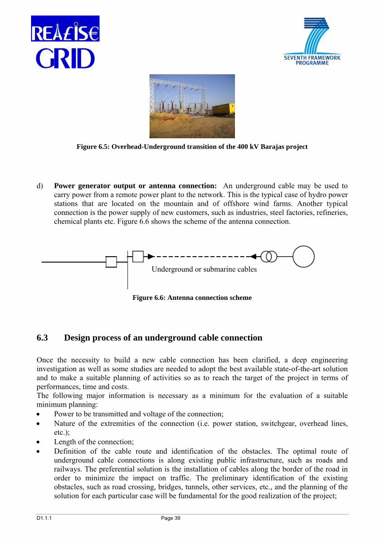
D1.1.1 Page 39
Figure 6.5: Overhead-Underground transition of the 400 kV Barajas project
d) Power generator output or antenna connection: An underground cable may be used to carry power from a remote power plant to the network. This is the typical case of hydro power stations that are located on the mountain and of offshore wind farms. Another typical connection is the power supply of new customers, such as industries, steel factories, refineries, chemical plants etc. Figure 6.6 shows the scheme of the antenna connection.
Figure 6.6: Antenna connection scheme
6.3 Design process of an underground cable connection Once the necessity to build a new cable connection has been clarified, a deep engineering investigation as well as some studies are needed to adopt the best available state-of-the-art solution and to make a suitable planning of activities so as to reach the target of the project in terms of performances, time and costs. The following major information is necessary as a minimum for the evaluation of a suitable minimum planning: • Power to be transmitted and voltage of the connection; • Nature of the extremities of the connection (i.e. power station, switchgear, overhead lines,
etc.); • Length of the connection; • Definition of the cable route and identification of the obstacles. The optimal route of
underground cable connections is along existing public infrastructure, such as roads and railways. The preferential solution is the installation of cables along the border of the road in order to minimize the impact on traffic. The preliminary identification of the existing obstacles, such as road crossing, bridges, tunnels, other services, etc., and the planning of the solution for each particular case will be fundamental for the good realization of the project;
Underground or submarine cables

D1.1.1 Page 40
• Identification of the nature of the soil and of the hydro-geological and the climatic conditions along the road;
• Identification of the possible civil work techniques in each section of the route; • Design of the cable system, identification of the cable type and dimensions, installation design
and procedures, evaluation of the reciprocal impact on existing infrastructures due to magnetic field, induced voltage and thermal influence;
• Obtainment of administrative authorizations; • Realization of the project and commissioning; • Mark and clear identification of the cable route and record to the land registry office. One of the major aspects when planning an underground cable connection is the selection of the route and the definition of the right of ways. According to the experience, the preferential route is the adoption of existing infrastructures, such as existing roads, railways, tunnels, bridges, etc. Since these infrastructures are competence of public administrations, the procedure to obtain the authorization is in general simplified, being the number of the land owners reduced. In case of cable installation along public roads, the trenching operations can be realized on the side of the roads thus reducing the impact on the traffic.

D1.1.1 Page 41
7 INSERTION OF AC CABLES INTO THE TRANSMISSION GRID For the insertion of an AC cable link in a power transmission system particular attention needs to be paid to the evaluation of some cable parameters, which are very different from the traditionally well known parameters of the overhead lines. Overhead transmission lines are quite simple to design. The insulation between the wires is guaranteed by the distance in air; the major aspects that have to be taken into account are the size of the wires and the mechanical design of pylons that shall be able to support the weight of the wires in the worst environmental conditions, such as wind and ice storms. Other design aspects related to the overhead lines (i.e. the electrical parameters and the power to be transmitted) are evaluated case by case with consolidated procedures. The design of the underground cables system is on the other hand more complex. The insulation of the cable is more sophisticated and the structure more complex too; the approach for the design of the cable system is substantially different from that one of the equivalent overhead line. One of the major differences is represented by the electrical capacitance of a cable that is of the order of 20 times higher than the one of an overhead line of the same length. The capacitance of the cable introduces a reactive power load that is proportional to the square of voltage and the length of the circuit. The reactive power is detracting capability to the cable connection and a critical length of the cable connection is intended when the transmissible active power is reduced of the order of 5-15 %. Other aspects related to the overvoltages in no load conditions and during the transient operations have to be considered as well. When the length of the cable connection is higher than the critical length and the capacitive reactive power becomes too high or unacceptable for the system, reactive compensation (usually inductances in the form of shunt reactors) shall be applied preferably at the substations or in the proximity of one or both extremities of the cable connection. Indicatively, the critical length for the AC cable connections is of the order of 100 km for 150 kV, 60 km for 220 kV and 20 km for 400 kV: these lengths may be different case by case and are to be evaluated case by case depending on the capability of the grid to sustain such a reactive power load. Another important parameter that must be taken into consideration is the direct sequence impedance which assumes a lower value for AC cables and that may have a consequence in the evaluation of the load flow repartition in case of parallel meshed grids. At the same time, due to the low value of the zero sequence impedance for AC cables there may be a higher fault current of the system with respect to equivalent overhead lines. Underground cables have a well defined rating temperature that cannot be over-passed without affecting the service life performances. IEC standards offer a series of recommendations and guidelines for the calculation of the current rating of the underground cables for the continuous and transient load conditions including fault. All these guidelines are based on the principle that the recommended cable temperature during the specified conditions is not over-passed. The relation of the heat dissipation produced by the losses of a cable is the so-called Ohm thermal law that can be simplified and approximated as follows:
TtW θ
≈
where
W = total losses produced by the cable (conductor, dielectric, metallic screen) θt = Available temperature drop (equal to conductor’s temperature minus ambient temperature)
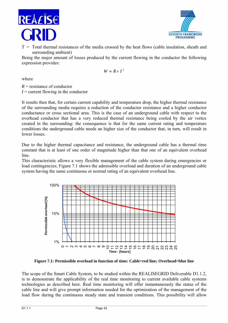
D1.1.1 Page 42
T = Total thermal resistances of the media crossed by the heat flows (cable insulation, sheath and surrounding ambient)
Being the major amount of losses produced by the current flowing in the conductor the following expression provides:
2IRW ×≈
where
R = resistance of conductor I = current flowing in the conductor It results then that, for certain current capability and temperature drop, the higher thermal resistance of the surrounding media requires a reduction of the conductor resistance and a higher conductor conductance or cross sectional area. This is the case of an underground cable with respect to the overhead conductor that has a very reduced thermal resistance being cooled by the air vortex created in the surrounding: the consequence is that for the same current rating and temperature conditions the underground cable needs an higher size of the conductor that, in turn, will result in lower losses. Due to the higher thermal capacitance and resistance, the underground cable has a thermal time constant that is at least of one order of magnitude higher than that one of an equivalent overhead line. This characteristic allows a very flexible management of the cable system during emergencies or load contingencies; Figure 7.1 shows the admissible overload and duration of an underground cable system having the same continuous or normal rating of an equivalent overhead line.
Figure 7.1: Permissible overload in function of time: Cable=red line; Overhead=blue line
The scope of the Smart Cable System, to be studied within the REALISEGRID Deliverable D1.1.2, is to demonstrate the applicability of the real time monitoring to current available cable systems technologies as described here. Real time monitoring will offer instantaneously the status of the cable line and will give prompt information needed for the optimization of the management of the load flow during the continuous steady state and transient conditions. This possibility will allow
1%
10%
100%
0 1 2 3 4 5 6 7 8 9 10 11 12 13 14 15 16 17 18 19 20 21 22 23 24 25
Perm
issi
ble
over
load
[%]
Time - [hours]

D1.1.1 Page 43
taking advantage of the intrinsic properties of the underground cable systems in relation to the characteristics described above in order to improve the efficiency of the power transmission in a safe and reliable condition.
It is rather frequent to make a comparison between underground cables and overhead lines. Often this comparison is not deemed appropriate because these two transmission technologies are fit for different applications. Considering underground cables, their most appropriate application is in the following situations:
• densely populated urban areas • areas where land is unavailable or consensus for overhead lines is difficult to obtain • rivers, sea and other natural obstacles • areas where land concerns outstanding natural historic or environmental significance • areas where land value must be maintained for future urban expansion and rural
development.
Some other advantages of underground power cables are:
• They are less subject to damage from severe weather conditions (mainly lightening, wind and freezing)
• The thermal time constant of underground cables is in the order of many hours or day and this allows a better management of the load during contingencies or emergencies (see Figure 7.1)
• Underground cables need a narrower surrounding to be kept permanently clear for safety and maintenance in case of repair (see Chapter 8)
• They are able to guarantee reduced electromagnetic fields (EMF) in the surrounding area, (see section 8.2) and provide no visual impact issues
• Underground cables pose no hazard to low flying aircrafts or to wildlife, and are significantly safer as they pose no shock hazard being totally screened.
Some drawbacks of underground power cables are:
• Undergrounding is more expensive, since the cost of burying cables at transmission voltages is several times higher than the one of overhead lines (see Chapter 9)
• Whereas finding and repairing the most frequent overhead wire breaks can be accomplished in hours, underground repairs, although rare, can take days or weeks (see Chapter 5)
• Operations are more difficult since the high reactive power of underground cables produces large charging currents, thereby making system design and voltage control more difficult.
Advantages and disadvantages shall be weighed case by case in order to choose the most suitable and convenient solution.

D1.1.1 Page 44
8 INSTALLATION OF UNDERGROUND CABLES The most common and simple installation of underground cable systems is the direct burial along the existing public roads. When the selection of this kind of route is possible then the procedures to obtain the authorization for the construction of new underground lines becomes simplified because only one counterpart has to be taken into consideration and it is not the case to enter into negotiation whit a high number of private owners. The standard installation of cable is the direct burial in trenches placed aside of the roads in order to minimize the impact on the traffic. After the cable installation the trenches are refilled with selected soil having good thermal properties for a better evacuation of the heat produced by the losses of the cables when subjected to the full load. In Figure 8.1 it is possible to see a typical drawing of the trench for the installation of one AC 400 kV cable system for the transmission of the power in the order of 1000-1500 MVA.
Figure 8.1: Scheme of the trench for the installation of EHV cables and live works
The picture represents the live works for the installation of the cables in the trench as indicated in the drawing. As it is possible to see, the trench is excavated along the edge of the road and some barriers are placed for the protection against the heavy traffic along a suburban road. In most cases more than one circuit of cables have to be installed for the transmission of the requested load. Figure 8.2 gives an idea of the soil occupied for the installation of four cable circuits in independent trenches that may transmit a total power of the order of 4-5 GVA when operated at the voltage of 400 kV AC. In presence of limited length obstacles along the selected route as for instance the road crossing, the configuration of the cables may be changed and other installation techniques may be adopted in order to overcome the obstacle. The document CIGRE TB 194 [19] gives the guidance for the construction, laying and installation techniques for extruded and self contained fluid-filled cable systems. Where the direct burial installation in trenches is not feasible for various reasons as it is in the case of a very crowded underground by other existing services, it is possible to install cables in dedicated tunnels of shared infrastructures, as indicated in Figure 8.3.

D1.1.1 Page 45
Figure 8.2: Soil occupation for the installation of four EHV cable circuits (source [29])
Figure 8.3: Installation of EHV cables in tunnel and vision of joints

D1.1.1 Page 46
8.1 Environmental impact of cables The impact of underground cables on the environment is different from that one of the overhead lines. The most evident is the impact of an overhead line on the landscape. This is immediately perceptible and, despite all the efforts devoted to improving a line’s insertion, an overhead line will always remain an artificial part of the landscape that is sometimes visible from great distances away. Obviously, the same is not true for an underground cable except during laying operations. Where an underground section is included in an overhead route, the transition site may have a significant visual impact. As mentioned already in this document (see Chapter 6 and Chapter 8), cables are generally laid in the public domain by installing them along existing roads. In rural areas, and if the cable is placed along public ways, because of the twisting of the road it may happen that the equivalent overhead line may have a straight and shorter route. Unlike overhead lines, the installation of underground links is greatly influenced by the ground in which the trench must be dug (for example, rocky soil makes a cable installation difficult), as well as any obstacles that have to be crossed. The works related to overhead lines only have significant impacts around the location of towers, whilst those ones concerning underground cables have a greater influence on the total route of the link (but not usually at the same time along the entire route). After installation work is complete, ground cultivation is allowed in both cases. Only the overhead line’s towers hinder cultivation. However the presence of an underground cable can be a problem for certain types of trees, which develop extensive root systems, the Figure 8.2 illustrates an idea of the distances to be respected in relation to the presence of high trees. Underground cables can be laid very close to the buildings, but it is recommended that no construction or civil work shall be realized directly above the underground cables, that shall be left free for any future events and for a correct thermal dissipation of the losses produced during the cables service. 8.2 Electromagnetic fields It is important to note that for the underground cables the electric field is almost completely confined inside the earthed metallic screen. For this reason no risk of electrocution is present and no serious injuries to the population have been noticed or known due to the presence of HV/EHV underground cables. The magnetic fields produced by buried cables and overhead lines are of the same order on the axis (that is directly below the overhead line and directly above the cable). The difference being that the magnetic field of the overhead line diminishes much more slowly than that one of the buried link with the distance from the circuit. In the case of a buried link the magnetic field becomes very low at only a few meters from the link axis. The example of a 150 kV link composed of one circuit with cable laid in trefoil formation at a depth of 1.4 m and subjected to a current of 900 A can be taken. At the same time an equivalent standard and conventional overhead line having the conductors suitably spaced in a triangle formation and carrying the same current, has been considered. The diagram of Figure 8.4 represents the magnetic flux density along a horizontal line at 1 meter above the ground surface considering a burial depth of 1.4 meters between the ground surface and the axis of the upper cable.

D1.1.1 Page 47
Figure 8.4: Magnetic field diagram for a 150 kV cable and 150 kV overhead line
The blue line indicates the magnetic field produced by the underground cable system as a function of the distance from the axis of the cable trench. As mentioned, it is possible that some cables have to be installed too close to a house or a place where a certain value of magnetic field shall not exceed the threshold set by the recommendations or requirements of national law or local regulations. In these circumstances, it may be necessary that the magnetic field produced by the cables should be shielded and suitable solutions can be applied for the reduction of the value of the generated magnetic field to the required level. Since these solutions may have an impact on the current rating of the underground cables as well as on the global cost of the system, their applications shall be limited to the portion of the circuit link where they are really necessary. The underground cables can be installed very close to the population residencies where national laws or regulations of some of the EU countries require the limitation of the exposure to the magnetic field. A number of countermeasures can be taken in order to mitigate the magnetic field produced by the cables as it can be summarized in the following:
• Arrangement of cables (the closer the cables, the lower the magnetic field) • The trefoil arrangement and the increase of the burial depth reduce the magnetic field on the
surface • Different types of magnetic field shield are available; the installation of cables in steel pipes
reduce the magnetic field to a negligible level; the same effect of shielding may be obtained with the installation of the cable in steel raceway
0,1
1,0
10,0
100,0
-20 -15 -10 -5 0 5 10 15 20
Distance from the vertical axis [m].
Mag
netic
fiel
d [m
icro
Tesl
a].
OHL lineCables in trefoil

D1.1.1 Page 48
• The use of passive loops formed by closed rings where the current induced by the main conductors produce a magnetic field contrary to the induced one. This solution is particularly suitable for the mitigation of the magnetic field in proximity of the joint bays: in fact, in this case the cable phases are more spaced in order to allow the joints installation. The larger the phases distance, the higher the magnetic field and a local mitigation of the magnetic field is necessary. In this situation the application of passive loops is more practical and convenient than the adoption of large steel pipes or raceways.
It should be noted that the studies on the effects on the human health due to the permanent exposure to magnetic field are still ongoing and no final common conclusions have been reached so far from the international medical research institutions. Due to this uncertainty, some countries and legislative institutions precautionarily limit the values of the magnetic field to be considered acceptable for permanent exposure on the basis of safety requirements or recommendations aiming at safeguarding the population’s health. Figure 8.5 shows some of the most common solutions that may be used for the magnetic field shielding as described above.
Figure 8.5: Different arrangement for the shielding of the magnetic field
Steel pipe Steel raceway
Passive loops

D1.1.1 Page 49
9 COSTS OF THE CABLE SYSTEM As already mentioned in Chapter 2, the definition of the costs of underground cable connections is a complex exercise that cannot be summarized with simple evaluations. In principle, the costs of cable connections depend on the voltage of the system, the power to be transmitted, and mainly on the route characteristics. A number of cost evaluations has been made in the past, mainly referred to the installation of cables in cities, which represented the most common and known utilization of underground cables. The installation of transmission cables in suburban or rural areas may have lower difficulties and cost of realization due to the absence of the numerous other underground services that are commonly present in cities. Some literature that addresses the issue of the cable cost is mentioned in the following references [1], [2], [3], [4], [23]. The evaluation of the costs of an underground cable system connection may be based on the following procedure that takes into consideration the full lifecycle:
• Planning/Design • Procurement • Construction • Operation • End of Life.
Each of the above stages of the project can be subdivided into further details and the split costs estimated. Based on a general experience, the early capital costs, particularly procurement and construction, are usually found to be the most significant for making decision. Since they are incurred immediately and tend to be larger than the operational costs, such as losses, repair and maintenance, they have the highest impact on the financing of projects. Underground cables have in general lower losses than overhead lines; however, this cost element may be very difficult to estimate. The magnitude of losses is highly dependent on how heavily the line will be loaded and the cost of losses depends on factors, such as the cost of fuel and the availability of surplus generation capacity. None of these factors are easy to estimate even in the short-term. Estimating their likely values in 40 years’ time is extremely difficult, particularly in a deregulated environment. By analysing underground cable costs for each stage of the cable’s life, it is easier to assess which costs are important and which estimates are least reliable. With the above caveat in mind, Table 9.1 provides some investment cost ranges for a 400 kV HVAC OHL at a typical rating of 1500 MVA for a single circuit (and respectively 3000 MVA for a double OHL circuit) and a 400 kV HVAC underground XLPE cable at a typical rating of 1000 MVA for a single circuit (and respectively 2000 MVA for a double circuit) 8. It is assumed that the investment costs include costs for equipment, project engineering and installation. The minimum
8 The rating of underground cables is not the same as the rating of the overhead lines since two cable circuits might be necessary in order to carry the same power of one overhead line.

D1.1.1 Page 50
value in the displayed ranges in Table 9.1 refers to installations in presence of lower labour cost, while the maximum value refers to installations in presence of higher labour cost. Also, the displayed costs refer to flat land installations: as a rule of thumb, in case of more difficult installations (e.g. on hills), the cost ranges shall be increased by 20%, while for extreme installation conditions (e.g. over mountains, in densely populated areas) the cost ranges shall be increased by 50%. The typical investment costs ranges displayed in Table 9.1 result from a collective exercise within REALISEGRID project with other project partners including TSOs. Table 9.1: Typical investment cost ranges for OHLs and underground XLPE cables, 400 kV HVAC
Components Rating
Typical cost range
Cost unit
HVAC OHL single circuit 1500 MVA 400 - 700 kEUR/km HVAC OHL double circuit 3000 MVA 500 - 1000 kEUR/km HVAC underground XLPE cable (single) 1000 MVA 1000 - 3000 kEUR/km HVAC underground XLPE cable (double) 2000 MVA 2000 - 5000 kEUR/km

D1.1.1 Page 51
10 ADVANTAGES AND DRAWBACKS OF MIXED SOLUTIONS: OHL-UNDERGROUND OR SUBMARINE CABLES
Mixed solutions featuring overhead and underground or submarine cables may sometimes constitute the best compromise. They have been often realized at very different voltage levels both for AC and DC connections. As described in section 6.2, point c), a mixed solution is in principle a connection composed by overhead lines and cables. This solution is also well known under the name of “siphon connection”, where the length of the underground portion may be only a few kilometers in the case of AC connections but may also be very long (hundreds of kilometers) in the case of DC ones. In principle this solution is used for very different cases, and it is particularly appreciated to overcome local problems that may be encountered with very long connections. 10.1 Relevant examples of mixed transmission lines A mixed solution may be an optimum compromise between cost and feasibility of a line. Some mixed solutions have been realized as the following examples show. They highlight only a few indicative applications: a number of similar important projects have also been realized but no detailed information is available for them. • 400 kV AC Barajas Airport Project in Madrid (Spain)
This project was realized as a consequence of the extension project of the Madrid airport in Spain where the construction of two new runways interfered with an existing 400 kV AC overhead line as indicated in Figure 10.1.

D1.1.1 Page 52
Figure 10.1: Undergrounding of the 400 kV Barajas project
Approximately 12.8 km of the 41.6 km long line were undergrounded; Figure 10.2 shows the complete underground arrangement of the connection.
Figure 10.2: Partial undergrounding of the 400 kV Barajas project
As the cable route interfered with the new runways, it was necessary to install the cables in a surface tunnel. In order to guarantee the requested load capability of the cables, a forced air ventilation for cooling the air in the tunnel was provided too. Each of the two cable systems were designed to carry the continuous load of 1720 MVA in winter and 1390 MVA in summer. Figure 10.3 shows the construction of the tunnel and the cables installed in the tunnel. The system has been in service since 2004. More details of the project are indicated in reference [25].
OHL TO BE UNDERGROUNDED
UNDERGROUND CABLE ROUTE
NEW RUNWAYS
LOECHES
MORATASAN SEBASTIÁN DE LOS REYES
41.6 km
UNDERGROUND CABLE
2.5 km 12.8 km
22.8 km 12.2 km
26.3 km

D1.1.1 Page 53
Figure 10.3: Construction of the tunnel and installation of 400 kV cables
• 400 kV AC Turbigo-Rho link in Italy
The total length of this 400 kV connection in Italy is approximately 40 km, 8.3 of which are underground. The schematic drawing of this connection is represented in Figure 10.4. The aim of this connection was to overcome limits to the generation in the Lombardy region that are presently caused by bottlenecks in the transmission network. This connection was considered of strategic importance also in order to increase the flexibility of the transmission system, to reduce transmission losses, with consequent advantages from environmental and economical point of view, and especially to avoid congestions, as mentioned. These congestions arise as a consequence of the significant power transiting in this area, partly due to the power imported from Switzerland and France. Removing these bottlenecks helps increasing the power availability and better covering consumption needs. In order to achieve a continuous rating of 2200 MVA as for the overhead line, the cable system was realized with two cables in parallel on each phase. The cables were mainly installed on the side of existing high traffic roads with a reduced impact on the traffic itself.
Figure 10.4: The 400 kV Turbigo-Rho line
The request and licensing process for the realization of an overhead transmission line was sent by ENEL in 1994. In 1996 the confirmation of the environmental compatibility was obtained, subject to few modifications of the proposed design. However, in the year 2000 the approval process was definitely stopped due to the opposition of the local communities. In consideration of the strategic importance of the interconnection, the Italian Transmission System Operator
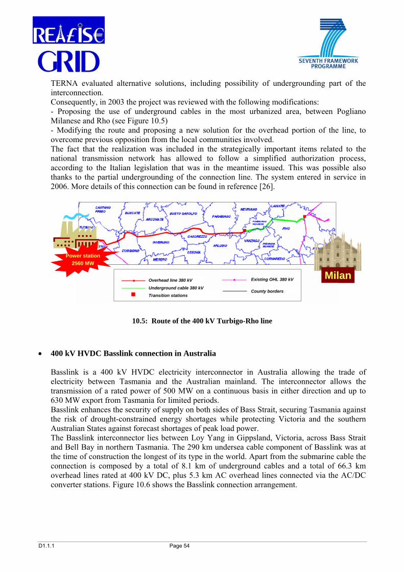
D1.1.1 Page 54
TERNA evaluated alternative solutions, including possibility of undergrounding part of the interconnection. Consequently, in 2003 the project was reviewed with the following modifications: - Proposing the use of underground cables in the most urbanized area, between Pogliano Milanese and Rho (see Figure 10.5) - Modifying the route and proposing a new solution for the overhead portion of the line, to overcome previous opposition from the local communities involved. The fact that the realization was included in the strategically important items related to the national transmission network has allowed to follow a simplified authorization process, according to the Italian legislation that was in the meantime issued. This was possible also thanks to the partial undergrounding of the connection line. The system entered in service in 2006. More details of this connection can be found in reference [26].
10.5: Route of the 400 kV Turbigo-Rho line
• 400 kV HVDC Basslink connection in Australia
Basslink is a 400 kV HVDC electricity interconnector in Australia allowing the trade of electricity between Tasmania and the Australian mainland. The interconnector allows the transmission of a rated power of 500 MW on a continuous basis in either direction and up to 630 MW export from Tasmania for limited periods. Basslink enhances the security of supply on both sides of Bass Strait, securing Tasmania against the risk of drought-constrained energy shortages while protecting Victoria and the southern Australian States against forecast shortages of peak load power. The Basslink interconnector lies between Loy Yang in Gippsland, Victoria, across Bass Strait and Bell Bay in northern Tasmania. The 290 km undersea cable component of Basslink was at the time of construction the longest of its type in the world. Apart from the submarine cable the connection is composed by a total of 8.1 km of underground cables and a total of 66.3 km overhead lines rated at 400 kV DC, plus 5.3 km AC overhead lines connected via the AC/DC converter stations. Figure 10.6 shows the Basslink connection arrangement.
Overhead line 380 kV
Underground cable 380 kV
Transition stations
Existing OHL 380 kV
County borders
Milan
Power station2560 MW
Overhead line 380 kV
Underground cable 380 kV
Transition stations
Existing OHL 380 kV
County borders
Overhead line 380 kV
Underground cable 380 kV
Transition stations
Existing OHL 380 kV
County borders
Milan
Power station2560 MW

D1.1.1 Page 55
Figure 10.6: 400 kV HVDC Basslink connection layout
• 200 kV Sardinia – Corsica - Italy (SACOI) link
The SACOI link, interconnecting the Italian Peninsula to the islands of Corsica and Sardinia, was one of the first worldwide HVDC connections being realized in 1965. At the beginning the system was operated as mono-polar line (see Table 4.3), i.e. there was only one cable operated at 200 kV for the transmission of a rated power of 200 MW and the electrical return path was through the sea. A second cable was added later and the transmissible power was increased. Today the system is a bipolar HVDC line. The total length of this connection is 388 km and is comprised of the following sections lines: A. 15 km overhead in Italy B. 105 km submarine cable between Italy and Corsica C. 167 km overhead in Corsica D. 14 km submarine cable between Corsica and Sardinia E. 87 km overhead in Sardinia. Figure 10.7 shows the layout of the Sardinia – Corsica – Italy connection.

D1.1.1 Page 56
Figure 10.7: 200 kV HVDC SACOI connection layout
10.2 Advantages and drawbacks of mixed lines The adoption of mixed solutions (overhead lines and underground or submarine cables) is in general the consequence of a detailed and careful evaluation and optimization of the connection. Table 10.1 summarizes the major characteristics of the transmission solutions traditionally applied. Table 10.1 provides elements for a first, qualitative comparison: as mentioned in this document, an effective comparison can be carried out only on a case by case basis, taking into account specific peculiarities of the individual projects.

D1.1.1 Page 57
Table 10.1: Comparison of the main characteristics of undergrounding transmission and overhead lines
Functional and environmental characteristics
AC Overhead
DC Overhead
AC Underground
DC Underground
Land use ■■■ ■■ ■ ■ Visual impact ■■■ ■■■ ■ ■ Acoustic impact ■■■ ■■■ ■ ■ Electrocution risk ■■■ ■■■ ■ ■ EMF ■■■ ■ ■■ ■ Losses ■■■ ■■■ ■■ ■ Impact on aviation ■■■ ■■■ ■ ■
Impact on flora/fauna ■■■ ■■■ ■ ■
Impact on building planning ■■■ ■■■ ■ ■
Length limitation ■■ ■ ■■■ ■ Reactive compensation ■ NA ■■■ NA
Reliability ■■■ ■■■ ■■■ ■■■
Cost of construction ■ ■ ■■■ ■■
Maintenance ■ ■ ■ ■ Time of repair ■ ■ ■■■ ■■■
Influence of weather ■■■ ■■■ ■ ■
Impact of catastrophic events ■■■ ■■■ ■ ■ Life expectancy ■■■ ■■■ ■■■ ■■■
Relative scale: ■ — Low; ■■ — Medium; ■■■ — High; NA — not applicable
D1.1.1 Page 58
11 OTHER INNOVATIVE CABLE TECHNOLOGIES Other innovative power transmission technologies are under development and some experimental applications have been realized. Today, the practical experience with these new technologies is limited and cannot be considered so mature as the power cables described in the previous Chapters; however, in particular cases they may find suitable use. 11.1 Superconducting cables The use of cryogenic liquid for cooling a high voltage cable only delivers significant advantages if the conductor losses are reduced through the use of superconductors to zero or virtually zero. Although transmission and distribution superconducting cables have been under research and development for several decades, so far only very few experimental installations have been realized all around the world. Benefits to power cables can immediately be recognized as lower electric losses, high electric efficiencies, and greater utilization of rights-of-way due to higher power density at a given voltage level. It must be taken into account that the global losses of superconducting cables are not negligible and the total power necessary to maintain the cryogenic liquid at the due temperature is today of the same order or even higher than the losses of the conventional cable systems. In general, superconductors are divided into two classes: low temperature and high temperature superconductors. Low temperature superconducting (LTS) cables have critical temperatures below approximately -233°C (40 K). This class of superconductors includes metals such as mercury (Hg) and metal alloys such as NbTi and NbSn. High temperature superconducting (HTS) cables have critical temperatures above approximately -233°C (40 K) and are cuprate ceramics. Examples include bismuth strontium calcium copper oxide (BSCCO) and yittrium barium copper oxide (YBCO). The first HTS materials were discovered in 1986. Some HTSC materials have the distinct advantage of critical temperatures above -196°C (77 K), putting them well within the temperature range of liquid nitrogen (LN), which is a low-cost, environmentally friendly coolant material. In addition to temperature, superconductors must be operated within critical boundaries of magnetic field and current density to exhibit zero resistance. Thanks to the development of HTS materials, practical applications have been made possible on power transmission cables and experimental circuits for some commercial applications.
11.1.1 Design of HTS cables Two major categories of HTS cables are taken into consideration: the room temperature dielectric (RTD), also called Warm dielectric, and the cryogenic dielectric (CD), also called Cold dielectric. In the RTD cables the insulation is placed outside the cold area while in the CD cables the insulation is placed inside the cold area. Figure 11.1 and Figure 11.2 show the two different types of HTS cables respectively.

D1.1.1 Page 59
Figure 11.1: Typical design of room temperature dielectric (RTD) superconductor cable
Figure 11.2: Typical design of cryogenic dielectric (CD) superconducting cable
11.1.2 Characteristics of HTS cables
The main features of superconducting cables are substantially different from those ones of conventional cables: in particular due to the negligible conductor resistance, it is possible to transmit high power at relatively low voltage and the line parameters are represented by the inductance and the capacitance. Table 11.1 summarizes the major differences between the two types of HTS cable design.

D1.1.1 Page 60
Table 11.1: Characteristics of HTS cable transmission systems
Type of HTS cable pros cons
Room temperature dielectric - RTD
• Proven dielectric - standard technology
• Low thermal losses • Cheaper than CD design
cables
• Stray magnetic field • Limited power/current • Minimum distance between
phases needed with present tape technology
Cryogenic dielectric - CD
• No stray field • No current/power limit • Direct contact between
phases possible
• 2 superconducting layers / higher cost
• More complicated construction • Higher thermal losses
As the dimension of HTS cables is lower than the one of conventional cables, a possible application of HTS cables is the retrofitting of obsolete circuits by using the same right-of-way or cable ducts, thereby increasing the amount of the transmitted power without changes or impact in the existing infrastructures. Figure 11.3 shows a RTD superconductor manufactured in 2001. Although the superconducting cables technology available today is suitable for niche applications in restricted circuits, it is still very far from a mature commercial application to be used for the extension of a power transmission grid. In particular, the failure of one superconducting cable that carries a high amount of power may create a contingency for the network. The superconducting cable system is very expensive and complex and is composed by a high number of parts that may be subject to individual risks of failure. Refrigeration, circulation system, vacuum pumps, cryostat, monitoring and data acquisition system are all critical components that should be redundant in order to guarantee a reasonable level of availability. The experience in service of the superconducting cable systems is very limited and a reliability analysis cannot be carried out with the same level of confidence that is used for the conventional cables described in this document.

D1.1.1 Page 61
Figure 11.3: 24 kV HTS cable with room temperature dielectric
11.2 Gas Insulated Lines The basic structure of a Gas Insulated Line (GIL) is similar to that one of well established gas insulated switchgear (GIS), in which the conductor at high voltage is located within an earthed conducting enclosure and the space between the two elements is filled with a gas under pressure to provide electrical insulation. The conductors are held in position by solid support insulators. The conductors of each phase may be located within separate enclosures (single phase enclosed). Compensation for thermal expansion is provided, often by sliding contacts in the conductor and, where the enclosure is free to move (i.e. in tunnel or trough installations), by bellows. The GIL is divided along its length into separate gas compartments. Figure 11.4 shows the general structure of a GIL. GIL dimensions are determined by dielectric, thermal and mechanical considerations. Conductor and enclosure diameters and thicknesses as well as gas composition and pressure may be varied according to the application to provide an optimum solution. In many cases, dielectric considerations will be predominant in determining dimensions and the required current rating will be achieved without difficulty. For more highly rated circuits, thermal considerations may be predominant and larger dimensions will be chosen to maintain temperatures within acceptable limits.
Liquid Nitrogen
Spacer/support
Flexible Support Tube
Outer Semi-conducting
Outer Screen Wires
Extruded Over-sheath
Extruded EPR Insulation
Inner Semi- conducting Layer
Outer Cryostat Tube
Inner Cryostat
Superconducting Tapes

D1.1.1 Page 62
Figure 11.4: Structure of a GIL
The GIL is insulated with either pure SF6 gas or a mixture of N2 and SF6. The pressure of the gas is depending from the purity and may vary from 2-3 bar for the pure SF6 up to 10 bar for a mixture of SF6 and N2 depending on the concentration. Compared to other technologies, GILs have some peculiar properties: the capacitance is reduced and no reactive compensation is necessary; conductors are of very large size and it is possible to transmit very high power with one single line; the magnetic field in the proximity of the line is negligible. Some environmental concerns are due to the greenhouse impact that may be represented by the high amount of SF6 gas necessary for the line filling. Today, the longest GIL circuit has been realized in Japan for the Shinmeika - Tokai link (see Figure 11.5): the circuit was designed to carry a power of 2850 MW at the voltage of 275 kV on a length of 3.3 km. Other circuits of shortest length (few hundred meters) have been realized; all the implemented circuits are with GIL installed in tunnel or above ground. Some buried pilot tests circuits have been realized but no directly buried GIL circuits in service are noticed till now [20], [21]. Recent GIL links in Europe have been installed in Germany (at Frankfurt airport) and in Switzerland.
Figure 11.5: View of the 275 kV Shinmeika - Tokai GIL ([20])

D1.1.1 Page 63
12 CONCLUSIONS In the last years, underground and submarine transmission cable technologies have benefited from the introduction of numerous innovative solutions. In some cases, the use of cables systems has represented non conventional solutions to power transmission issues. Transmission lines are strategically important and the adoption of innovative solutions is considered with care. The major innovations on cable systems are in the direction of increasing the reliability, safety, availability, and feasibility of the system. As reported by the CIGRE survey [22], a high intrinsic level of reliability has been reached for submarine connections; adopting similar approaches and same materials and technology, similar levels of reliability may be reached for underground cable connections. The same survey evidenced a certain rate of failures due to the external damages generally of mechanical nature and caused by third parties. It is expected that the precaution and rules adopted during the last years for the installation of both submarine and underground cables will strongly reduce these kinds of failures. Underground transmission cable systems are more complex than equivalent overhead lines and, even though a strong rationalization and optimization will be possible in the future, their initial investment cost will remain higher. A more detailed evaluation of the global costs taking into account the lower losses during the whole period of life, the cost of soil occupation and the timing for the authorization process may strongly reduce or invert these cost differences. Other aspects, such as those related to the visual impact, cannot be easily evaluated. General assumptions cannot be carried out beforehand and only detailed and complete evaluations on specific projects based on an effective and actual techno-economic comparison can lead to the selection of the optimal option. The electromagnetic field (EMF) emissions of transmission lines are today regulated by national laws in some European countries. These provisions have mainly a precautionary aim, because the impact of electromagnetic fields on the human health has not yet been clearly identified. The difference between overhead lines and cables is that cables can be laid very close to houses or population residencies; the magnetic field may be very high just close to the cable, although it quickly decays to negligible values when the distance from the cable increases. Overhead lines may have the same level of magnetic field close to the line; however, the value may remain high even at a considerable distance. If necessary, the magnetic field produced by cables can be screened at any distance from the cable till to the requested or negligible value. The selection of the most suitable transmission cable system requires a complex study. Cable technologies are available to cover almost all the possible needs. While HVAC cable systems may be useful for the completion and reinforcement of the transmission grid, HVDC cable systems may be used for long submarine connections, as well as for land interconnections or power feeding of remote areas. At the same time the characteristics of the HVDC underground or submarine transmission systems may represent a valid solution for the future realization of new private merchant lines, which will allow improving energy trade and creating general benefits for the users in terms of security of supply and improvement of the robustness of the grid. Superconductors and GILs are very innovative available technologies that may be used for specific applications; more developments and service experience will be required before starting with an extended use of these systems.

D1.1.1 Page 64
Long distance transmission allows remote renewable energy resources to be used to displace fossil fuel-based generation and to reduce CO2 emissions, which are at present the major targets of the most developed countries. Hydro and wind sources cannot be moved closer to densely populated cities and industrial locations and future development of solar energy will be possible at lower costs in remote areas where local power needs are minimal. Connection costs of such remote renewable energy resources are a key element to determine whether any particular renewable alternative is economically feasible. In that respect, the HVDC transmission technology may represent the most appropriate solution for the connection over long distances both in land and sea.

D1.1.1 Page 65
13 REFERENCES [1] Cigre B1-301, Benato, R.; Del Brenna, M.; Di Mario, C.; Lorenzoni, A.; Zaccone E.:
A New Procedure To Compare The Social Costs Of EHV-HV Overhead Lines And Underground XLPE Cables 2006
[2] Cigre B1-211, Jensen, C. ; Argaut, P.: 400 kV Underground Cables in Rural Areas 2006
[3] Cova, B.; deNigris, M.; Ardito, A.: Analyse des besoins pour une nouvelle interconnexion entre la France et l’Espagne – 2008, Document prepared by CESI for the European Commission.
[4] Allen, S.: Economics of high voltage cable systems Jicable 2007 B1.10.
[5] Fara, A.; Zaccone, E.: Development of high voltage extruded cables – The Italian experience Jicable 2007 – A15.
[6] P.Argaut, K.B.Larsen, F. Shell, W. Wasch, E. Zaccone: Large projects of EHV underground cable systems – Jicable 2007 – A21
[7] EPRI : Underground Transmission Systems Reference Book 2006.
[8] IEC 62067: Power cables with extruded insulation and their accessories for rated voltages above 150 kV (Um = 170 kV) up to 500 kV (Um = 550 kV) - Test methods and requirements.
[9] IEC 60840: Power cables with extruded insulation and their accessories for rated voltages above 30 kV (Um = 36 kV) up to 150 kV (Um = 170 kV) – Test methods and requirements.
[10] IEC 60287: Electric cables - Calculation of the current rating – series of standards.
[11] IEC 60853-2: Calculation of the cyclic and emergency current rating of cables.
[12] IEC 60949 Calculation of the thermally permissible short circuit currents, taking into account non adiabatic effects.
[13] CIGRE TB 219: Recommendations for testing DC extruded cable systems for power transmission at a rated voltage up to 250 kV February 2003.

D1.1.1 Page 66
[14] Electra: Recommendations for electrical test prequalification and development on extruded cables and accessories at voltages above 150 kV (Um=170kV) and up to and including 400 kV (Um=420kV). 1993, N° 151-
[15] Electra : Recommendations for electrical test prequalification and development on extruded cables and accessories at voltages above 150 kV (Um=170kV) and up to and including 500 kV (Um=550kV). 2000, N° 193
[16] Electra : Recommendations for mechanical Tests on Submarine Cables. 1997, N° 171 -
[17] Electra : Recommendations for tests of power transmission DC cables for a rated voltage up to 800 kV (Rev. of edition 1980) 2000, N° 189
[18] CIGRE TB 338: Statistics of AC underground cables in power network December 2007
[19] CIGRE TB 194 : Construction, laying and installation techniques for extruded and self contained fluid filled cable systems. October 2001
[20] CIGRE TB 218: Gas Insulated Transmission Lines (GIL) February 2003
[21] CIGRE TB 351: Application of Long High Capacity Gas-Insulated Lines in Structures October 2008
[22] CIGRE TB 379: Update of service experience of HV underground and submarine cable systems April 2009
[23] ICF Consulting: Overview of the Potential for Undergrounding the Electricity Networks in Europe Prepared for the DG TREN/European Commission Study; Contract No 2002/009/C2
[24] Electra: Application of Weibull distribution to the study of power cables insulation. 1989 , N° 127
[25] Granadino R., Portillo M., Planas J., Schell F.: Undergrounding the first 400 kV transmission line in Spain using 2 500 mm2 XLPE cables in a ventilated tunnel: the Madrid « Barajas » airport project Jicable 2003, A.1.2
[26] Rendina, R. ; Posati, A.; Rebolini, M. ; Bruno G.; Bocchi, F.; Marelli, M. ; Orini, A.; The New Turbigo-Rho 380 kV Transmission Line: An Example Of The Use Of Underground Xlpe Cables In A Meshed Transmission Grid CIGRE 2006 – B1.302

D1.1.1 Page 67
[27] University of Leicester:
Benefits of HVDC Links in the European Power Electrical System and Improved HVDC Technology, EC Contract No: ENK6-CT-2002-00670, http://www.le.ac.uk/eg/hvdc/ProjectPartners.html.
[28] Cigre, TB 269 Working group B4.37 : VSC Transmission April 2005
[29] Europacable: Extra-high voltage Underground Power Cables – Facilitating and Enabling Europe’s electricity supply, June 2009