d1801 installation instructions dodge ram 2003-13 2500, 03...
TRANSCRIPT

»Zone Offroad Products • 491 W. Garfield Ave., Coldwater, MI 49036 • 888.998.ZONE • www.zoneoffroad.com
Read and understand all instructions and warnings prior to installation of product and operation of vehicle.Zone Offroad Products recommends this system be installed by a professional technician. In addition to these instructions, profes-sional knowledge of disassembly/ reassembly procedures and post installation checks must be known. Minimum tool requirements include the following: Assorted metric and standard wrenches, hammer, hydraulic floor jack and a set of jack stands. See the "Special Tools Required" section for additional tools needed to complete this installation properly and safely.
»Product Safety Warning
Certain Zone Suspension Products are intended to improve off-road performance. Modifying your vehicle for off-road use may result in the vehicle handling differently than a factory equipped vehicle. Extreme care must be used to prevent loss of control or vehicle rollover. Failure to drive your modified vehicle safely may result in serious injury or death. Zone Offroad Products does not recom-mend the combined use of suspension lifts, body lifts, or other lifting devices.
You should never operate your modified vehicle under the influence of alcohol or drugs. Always drive your modified vehicle at re-duced speeds to ensure your ability to control your vehicle under all driving conditions. Always wear your seat belt.
»technical SuPPort
www.zoneoffroad.com may have additional information about this product including the lat-est instructions, videos, photos, etc.
Send an e-mail to [email protected] detailing your issue for a quick response.
888.998.ZONE Call to speak directly with Zone tech support.
»Pre-inStallation noteS
1. Special literature required: OE Service Manual for model/year of vehicle. Refer to manual for proper disassembly/reassembly procedures of OE and related components.
2. Adhere to recommendations when replacement fasteners, retainers and keepers are called out in the OE manual.
3. Larger rim and tire combinations may increase leverage on suspension, steering, and related components. When selecting combinations larger than OE, consider the additional stress you could be inducing on the OE and related components.
4. Post suspension system vehicles may experience drive line vibrations. Angles may require tuning, slider on shaft may require replacement, shafts may need to be lengthened or trued, and U-joints may need to be replaced.
5. Secure and properly block vehicle prior to installation of Zone Offroad Products. Always wear safety glasses when using power tools.
6. If installation is to be performed without a hoist, Zone Offroad Products recommends rear alterations first.
7. Due to payload options and initial ride height variances, the amount of lift is a base figure. Final ride height dimensions may vary in accordance to original vehicle attitude. Always measure the attitude prior to beginning installation.
rev062117
D1801 Installation InstructionsDodge Ram 2003-13 2500, 03-12 35006-8" Suspension System
Difficulty Leveleasy 1 2 3 4 5 difficult
Estimated installation: 6-8 hours
Special Tools RequiredPitman arm puller
Reciprocating Saw w/ long blade
Tire/Wheel Fitment6" - 37 x 12.50, 17x9 w/ 4.5-5" BS
8" - 38 x 13.50, 17x9 w/ 4.5-5" BS

D1801 Installation - pg. 2
Kit ContentsQty Part
2 Coil Springs
»d1801 Box Kit
Qty Part
2 Upper Control Arm Bracket2 Upper Control Arm Crush Sleeve1 Upper Control Arm Bolt Pack1 Lower Control Arm Bracket - Drv1 Lower Control Arm Bracket - Pass1 Lower Control Arm Bolt Pack1 Rivet Nut Bolt Pack2 1/2-13 Rivet Nut1 Loctite2 Bump Stop Bracket2 Urethane Bumpe Stop1 Bump Stop Bolt Pack1 3/8" x 1" Bolt1 3/8" Hex Nut1 3/8" Lock Washer1 3/8" USS Flat Washer1 Rear Brake Line Drop Bracket
»d1802/d1803/d1804 Box KitS
Qty Part
1 Pitman Arm1 Track Bar Bracket1 Track Bar Bracket Bolt Pack2 Sway Bar Link2 Sway Bar Link U-Bracket2 5/8" ID Hourglass Bushing2 3/4" ID Hourglass Bushings2 .625 x .109 x 1.375 Sleeve2 .750 x .090 x 1.575 Sleeve1 Sway Bar Link Bolt Pack1 Sway Bar Link Axle Mount Drv (1803/1804 only)1 Sway Bar Link Axle Mount Pass (1803/1804 only)1 Rear Brake Line Bracket (1802 only)
»d1418/d1419/d1508/d1509 rear Box KitS
Qty Part
2 4" Lift Block (6" Kit only)2 5" Flat Block w/ BS (8" Kit only)4 9/16 x 3-1/2 x 14 1/2 U-bolt (D1419 only)4 9/16 x 4 x 14 1/2 U-bolt (D1418 only) 8 9/16" High Nut8 9/16" SAE Washer2 Steel Press-In Center Pin
»d5805 t-caSe indexing ring Kit
(Included with 2003-'08 8" kits only)
Qty Part
1 Front Driveshaft Spacer1 T-case Indexing Ring1 Driveshaft Spacer Bolt Pack1 Indexing Ring Bolt Pack - Standard1 Indexing Ring Bolt Pack - Metric1 Seal Extension1 Rear Output Seal1 Loctite
» t-caSe indexing ring Kit
(Included with 2009-'13 8" kits only)
Qty Part
1 Front Driveshaft Spacer1 T-case Indexing Ring1 Driveshaft Spacer Bolt Pack1 Indexing Ring Bolt Pack - Standard1 Seal Extension1 Rear Output Seal1 Loctite
*Important* Verify you have all of the kit components before beginning installation.
D1801 Installation - pg. 3
INSTALLATION INSTRUCTIONS
»Pre-inStallation note
1. PowerWagon Models: These models come from the factory with a 2" taller ride height compared to the standard models. When adding the 6" suspension system, the net lift will be 4" over the factory PowerWagon suspension height, which will be equivalent to a standard model's height with the same lift.
»front inStallation
1. Park the vehicle on a clean, flat surface and block the rear wheels for safety.
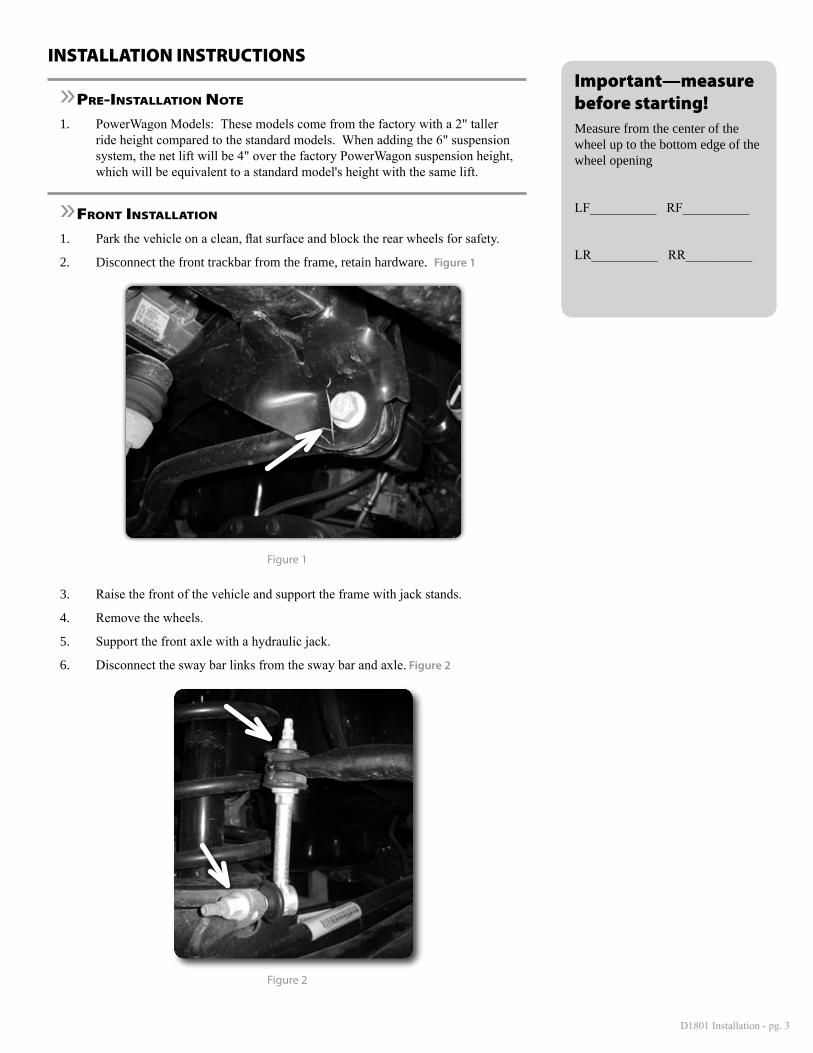
2. Disconnect the front trackbar from the frame, retain hardware. Figure 1
Figure 1
3. Raise the front of the vehicle and support the frame with jack stands.
4. Remove the wheels.
5. Support the front axle with a hydraulic jack.
6. Disconnect the sway bar links from the sway bar and axle. Figure 2
Figure 2
Important—measure before starting!Measure from the center of the wheel up to the bottom edge of the wheel opening
LF__________ RF__________
LR__________ RR__________

D1801 Installation - pg. 4
7. Disconnect the brake lines from the axle brackets. Figure 3.
Figure 3
8. Remove the factory bump stops from the frame. Pull them free of the frame mount with channel lock pliers or hit them sideways with a hammer to dislodge.
9. Disconnect the drag link from the pitman arm. Use caution not to damage the boot. Retain hardware. Figure 4
10. Remove the pitman arm nut from the sector shaft. Mark the position of the pitman arm, this position will be transferred over to the new pitman arm. Figure 4
Figure 4
11. Transfer the index mark over to the new pitman arm. Install the new pitman arm on the shaft by lining up the splines on the pitman arm and sector shaft so that the indexing is correct. Fasten the pitman arm with the stock hardware and torque to 185 ft-lbs. Do not connect the drag link at this time.

D1801 Installation - pg. 5
Leave disconnected
Figure 5
12. On both sides of the vehicle, make index marks on the alignment eccentrics at the axle Figure 6. Mark the cams to indicate driver’s verses passenger’s side.
Figure 6
13. Ensure that the axle is well supported and remove the lower control arm cam bolts. Disconnect the lower control arms from the frame and remove them from the vehicle. Retain hardware.
14. Remove the four bolts mounting the factory transmission skid plate, this will not be re-used. Figure 7
Figure 7
Step 13 NoteOn older model vehicles the cams may become corroded into the control arms. If this is the case, a ball joint press tool may be used to press the bolts out. If this method is not successful, the cam bolts must be cut and replaced by new hardware available through Chrysler.

D1801 Installation - pg. 6
15. Drill the existing holes in the crossmember as shown to 11/16 for rivet nut installation. Figures 8 &9.
Figure 8 - Passenger side shown
Figure 9 - Driver side shown
16. Install rivet nuts using provided rivet nut installation tool. See detailed instruc-tions at the end of this instruction sheet.
»tranSfer caSe indexing ring inStallation (8" KitS only)17. Install the indexing ring at this time, reference the individual box kit instructions
specific to the model year of the truck.
»control arm BracKet inStallation
18. Perform steps 43-48 on one side at a time starting with the passenger side. Support the crossmember with a jack and remove the 2 bolts on the side of the crossmember Figure 10 Install the relocation bracket using the provided 9/16" x 7" bolts, nuts, and washers with the bolts going rear to front. Use the provided 5/8" x 4" bolts, nuts, and washers at the OE mount. Lastly install the 1/2" x 1-1/2" bolt with washer at the rivet nut location. Tighten 5/8" hardware to 150 ft-lbs. 9/16" to 125 ft-lbs, and 1/2" to 65 ft-lbs.
Step 16 NoteRivet Nut Installation tool is lo-cated in bolt pack 799.
Step 18 NoteLower control arm bracket hard-ware is located in bolt pack 670.
D1801 Installation - pg. 7
Figure 10
19. Disconnect the upper control arm from the frame and the axle. Retain hardware. Locate the upper control arm relocation bracket. Place the bracket on the axle mount and align the original control arm mounting hole with the hole in the new bracket and temporarily install a 9/16" x 5" bolt.
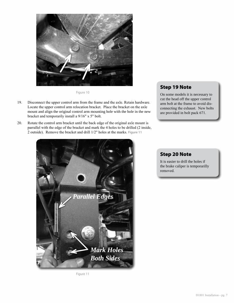
20. Rotate the control arm bracket until the back edge of the original axle mount is parrallel with the edge of the bracket and mark the 4 holes to be drilled (2 inside, 2 outside). Remove the bracket and drill 1/2" holes at the marks. Figure 11
Parallel Edges
Mark Holes Both Sides
Figure 11
Step 19 NoteOn some models it is necessary to cut the head off the upper control arm bolt at the frame to avoid dis-connecting the exhaust. New bolts are provided in bolt pack 671.
Step 20 NoteIt is easier to drill the holes if the brake caliper is temporarilly removed.

D1801 Installation - pg. 8
21. Once all of the holes are drilled, reattach the bracket to the axle and install the 9/16" x 5" bolt, washers, and nut with the 7/8" x 2-3/8" sleeve at the factory up-per control arm location. Install the 1/2" x 1-1/2" bolts, nuts, and washer in the four drilled holes . Leave loose, hardware will be tightened once the control arm is installed.
22. Install the the lower control arm in the frame bracket and axle mount locations with the original hardware. Leave hardware loose.
23. Ensure that the brake line is running above the lower control arm and under the upper control arm. Install the upper control arm with the original hardware (or new hardware (included) if required). Install the hardware at the axle from the outside facing inside. Torque UCA bracket 1/2" hardware to 65 ft lbs and 9/16" hardware to 95 ft lbs. The control arm will be tightened once the vehicle is on the ground.
24. Repeat the control arm bracket installation on the drivers side, steps 43-48
Figure 12
Step 23 NoteIf you are having difficulty lining up the upper control arm bolts, disconnect the drivers side uppper control arm to ease installation.

D1801 Installation - pg. 9
»coil SPringS, BumP StoPS, tracK Bar BracKet inStallation
25. Open the hood and with the axle well supported remove the upper shock stem nuts. Figure 13
Figure 13
26. Disconnect the shock from the lower mount. The head of the bolt is accessed through a hole in the front of the axle spring perch.
27. Lower the jack until the shocks and springs can be removed from the vehicle. Also, remove the upper spring isolator. The isolator will be reused. Figure 14
Figure 14

D1801 Installation - pg. 10
28. Locate the 2 recesses inside the factory bump stop cup. Drill the center of the indentations to 5/16" and cut threads into the frame with 3/8" self threading bolts. Remove the bolts and attach the bump stop drop brackets with 3/8" hardware. Loc-tite the threads. Figure 15
Figure 15
29. Install the new bump stops into the drop brackets with 3/8" nuts, washers, and lock washers.
30. Lightly grease and install the shock bushings and sleeves into the front shocks. Place the cup washer and stem bushing on the top stud.
31. Install the original spring isolators on top of the new coil springs. Place the shock inside the coil and install the coil springs in the vehicle.
32. Install the lower shock hardware and torque to 75 ft-lbs. Slightly compress the coils and attach the upper shock stem hardware. Tighten until the bushings begin to swell.
33. Install the new track bar bracket to the factory frame mount with the 9/16 hardware (03-07) or 5/8" hardware (08+). Attach the end of the bracket to the frame crossmember with the 9/16 hardware Figure 16 Torque the 9/16 hardware to 125 ft-lbs, 5/8" hadware to 150 ft-lbs (if applicable). Do not install the trackbar at this time.
Figure 16
Step 28 NoteBump stop drop hardware is lo-cated in bolt pack #785.
Step 31 NoteIt may be necessary to lower the axle with the jack to install the new springs and shocks.
Step 33 Note03-07 Trackbar hardware is 9/16" x 3" is located in bolt pack # 609
08 + Trackbar hardware is 9/16" x 3 and 5/8" x 3" Located in bolt pack # 642

D1801 Installation - pg. 11
»SWay Bar linK inStructionS
Note: Powerwagon models refer to sway bar link instructions located in the D5301 kit.
34. Grease and install the longer hour glass bushings into one end of the sway bar link with the 3/4" x 1.575" sleeve. Grease and install the shorter bushings into the other end with the 5/8" x 1-3/8" long bushings.
35. Attach stem eliminator bracket to the sway bar with 5/8" nylock nut with washer. Tighten securely.
36. Install the sway bar link with the small bushings into the stem eliminator bracket with 3/8" hardware.
37. For '09 and newer models with a solid tie rod (T-Link Steering) attach the other end of the sway bar link to the axle with 9/16" hardware. Run the bolts from inside to the outside of the vehicle. Figure 17 It may be necessary to slighly clearance the holes to accept the 9/16" hardware.
Figure 17
38. 03-08 models with y-link steering (drag link connects from pitman arm directly to the steering knuckle) do not have enough clearance to the sway bar mounts. If you have an 03-08 model with the new T-link setup, installation of the brackets is still required due to the length of the sway bar links included in the kit.
39. Disconnect the tie rod end from one of the steering knuckles and swing the whole assembly out of the way.
40. Disconnect the trackbar from the axle. Retain nut tab.
41. Cut the welds on both sides of the sway bar link mount at the axle. Remove the brackets from the vehicle.
42. Clean the area with a flap wheel or grinding wheel.
Step 35 NoteSway bar link hardware is located in bolt pack 783. '09 and newer models will have left over hard-ware.

D1801 Installation - pg. 12
43. Place the sway bar mounting bracket against the axle as shown. Figure 18 The passenger side will use the factory trackbar hole. Mark and drill the other hole to 1/2".
Figure 18
44. Attach the bracket to the axle with the trackbar in position with new trackbar bolt and washer (14mm 03-07 / 16mm 08+) with factory nut tab, and ½" bolt (with loc-tite), with washer on the outside and square nut on the inside. The square nut will rest against the inside gussets of the axle and eliminate the need for a wrench. Tighten the ½" hardware to 65 ft-lbs. Do not tighten the trackbar mounting bolt at this time. (Fig 26)
45. Repeat installation for drivers side. Align the bracket with the existing hole. Mark the opposite hole and drill both holes to1/2". Reinstall the bracket with 1/2" bolts (with loc-tite) with washers on the outside and square nuts on the inside of the bracket. Tighten to 65 ft-lbs. Figure 19
Figure 19
46. Attach the sway bar link to the new axle bracket with 9/16" hardware. Run the bolts from inside to the outside of the vehicle.
Step 44 NoteSway bar link bracket hardware is located in bolt pack 783. Depend-ing on model year, there will be either an extra 14mm or 16mm bolt leftover.

D1801 Installation - pg. 13
»front inStallation - final aSSemBly
47. Attach the drag link to the new pitman arm with the factory nut. Torque to 55 ft-lbs. Figure 5
48. Attach the brakeline to the upper control arm axle bracket with the provided 5/16: self-tapping bolts. Tighten to 25 ft-lbs. Figure 20
Figure 20
NOTE: Before hooking up the front driveshaft, now is a great time to grease the nearly impossible to access grease fitting on the front dual cardan joint. A needle adaptor on a grease gun is required. This fitting is required to be serviced at every oil change interval. Ensure that this maintenance is not skipped!
49. Reinstall front driveshaft. 8" kits only - Install the driveshaft spacer using new hardware. Use loctite on threads and tighten to 75 ft-lbs. Figure 21
Figure 21
50. Reinstall wheels and lower the vehicle to the ground. Tighten lug nuts to factory specifications.
51. Tighten control arm hardware as follows: 14mm upper arm hardware 120 ft-lbs, ¾" Lower at frame 160 ft-lbs. Adjust axle cam bolts to the original position and torque 16mm bolts to160 ft-lbs (03-09 models only) and 18mm cam bolts to 180 ft-lbs (2010+ models only).
Step 47 NoteNotice the tie rod taper has been re-versed from the factory pitman arm to improve the steering geometry.
Step 49 NoteHardware for front driveshaft spacer is located in bolt pack 932.

D1801 Installation - pg. 14
52. Attach the trackbar to the relocation bracket with 14mm hardware (03-07) or 5/8" hardware (08+). Tighten 14mm hardware to 120 ft-lbs at axle and reloca-tion bracket. Tighten 5/8" hardware to 150 ft-lbs.
53. Double check all components for proper torque.
»rear inStallation
1. Block the front wheels. Raise the rear of the vehicle and support the frame with jackstands. Remove the rear wheels.
2. Support the rear axle with a hydraulic jack.
3. Disconnect the rear shock hardware, keep hardware for reinstallation, discard the shocks.
4. Disconnect the parking brake cable at the junction block in front of the rear spring hanger.on the drivers side. Measure the amount of exposed thread before loosening the adjuster for reassembly. Disconnect the drivers side rear cable.Figure 22
Figure 22
5. Disconnect the rear brake line bracket from the axle by removing the vent line. This is done to gain adequate slack for lift block installation. Figure 23
Figure 23

D1801 Installation - pg. 15
6. Working on one side, disconnect the u-bolts and lower the axle. Remove the plastic center pin and install the new metal one. It may be necessary to take a die grinder to slightly enlarge the opening in the lowest leaf. This should be a snug to press fit.
7. Install the new lift block between the axle and spring pack. Install new u-bolts. Snug the u-bolts at this time, but do not tighten. Figure 24
Figure 24
8. Repeat block installation for the opposite side.
9. Lightly grease and install the bushings and sleeves into the new shocks. Install the shocks with the factory hardware.
10. Reroute the drivers side parking brake cable behind the spring hanger and reat-tach it to the junction block. Figure 25
Step 6 NoteIt may be necessary to loosen the u-bolts on the opposite side to al-low the axle to droop far enough from the spring to insert the new lift block..

D1801 Installation - pg. 16
Figure 25
11. 2003-11 models only- Locate the rear brake line mount at the frame. Remove the hardline retaining clip from the brake line. Pull the brake line towards the rear to release it from thr bracket.
12. 2003-11 models only - Carefully cut a 1/4" wide slot in the factory brake line mount to the brake line hole. This will allow the brake line to be removed from the bracket without disconnecting the brake line. Remove the hardline from the bracket.
13. 2003-11 models only - Locate the provided brake line bracket. This will mount with the bend down and towards the front. Fasten with a 3/8" x 1" bolt, nut, flat washer, and lock washer. That flat washer will go over the large hole in the fac-tory bracket. Reattach the brake line to the axle. Torque hardware to 30 ft-lbs.
14. 2012 and newer models only - Remove the brake line bracket from the brake lines, this can be done by cutting slots in it with a small cut off wheel to avoid having to disconnect the lines and bleed the brakes.
15. 2012 and newer models only - Install the provided brake line relocation bracket with the provided sleeve and original vent. Reform the lines to line up with the bracket and attach them to the brake line bracket with the factory clips Figure 26.
16. Reinstall the wheels and lower the vehicle to the ground.
17. Torque the u-bolts to 110-125 ft-lbs.
18. Recheck all fasteners and lug nuts for proper torque, again after 500 miles, and at regularly scheduled maintenance intervals.
Figure 26
Post-Installation Warnings1. Check all fasteners for proper torque. Check to ensure for adequate clearance between all rotating, mobile, fixed, and heated members. Verify clearance between exhaust and brake lines, fuel lines, fuel tank, floor boards and wiring harness. Check steering gear for clearance. Test and inspect brake system.
2. Perform steering sweep to ensure front brake hoses have adequate slack and do not contact any rotating, mobile or heated members. Inspect rear brake hoses at full extension for adequate slack. Failure to perform hose check/ re-placement may result in component failure.
3. Perform head light check and adjustment.
4. Re-torque all fasteners after 500 miles. Always inspect fasteners and components during routine servic-ing.
Step 13 NoteHardware for the rear brake line is located in the D1801 box kit.

D1801 Installation - pg. 17
Rivet Nut Installation Instructions
»hole PreParation
1. Drill hole to appropriate size for rivet nut installation. 1/2" Rivnuts require an 11/16" hole and 3/8" Rivnuts require a 17/32" drill. It is crititcal that this hole is drilled to the correct size. Remove any burrs that could keep the rivet nut from seating flat against either side of the hole surface. Figure 1.
Figure 1
»rivet nut inStallation tool aSSemBly
2. For a 3/8" rivet nut, place the provided 3/8" SAE flat washer on the 3/8" x 1-1/2" bolt, followed by 7/16" hex nut and then a 3/8" serrated washer. Figure 2 Thread this tool assembly into the rivet nut.
3. For a 1/2" rivet nut, place the provided 1/2" SAE washer on a 1/2" x 2" bolt fol-lowed by a 9/16" high nut and 1/2" serrated edge lock washer. Thread this tool assembly into the rivet nut as shown. Figure2.
Figure 2 - 1/2" Rivet Nut Shown
Step 1 NoteIf the correct drill size is not avail-able, it is possible to drill the hole to an available smaller size and slowly grind it out to until the rivet-nut fits tight.

D1801 Installation - pg. 18
»rivet nut inStallation
4. Verify the correct size rivet nut for the application based on the thickness of material where the rivet nut is to be installed using the following chart.
Part Number
ThreadSize
Body Length (in)
Material Thickness(in)
Drill Size (in)
Min. Max.95105A159 3/8-16 .690 .027 .150 17/3295105A168 3/8-16 .805 .150 .312 17/3295105A169 1/2-13 1.150 .063 .200 11/1695105A170 1/2-13 1.300 .200 .350 11/16
5. Place the installation tool with the rivet nut threaded on the end into the appro-priately sized hole.
6. For a 3/8" rivet nut, hold the nut closest to the rivet nut still with an 5/8" wrench and tighten the 3/8" bolt with a 9/16 wrench to set the rivet nut. Be sure to hold the rivet nut flush to the surface and square to the hole as it is tightened. Figure 4
7. For a 1/2" rivet nut, hold the nut closest to the rivet nut still with an 7/8" wrench and tighten the 1/2" bolt with a 3/4" wrench to set the rivet nut. Be sure to hold the rivet nut flush to the surface and square to the hole as it is tightened. Figure 3
Figure 3 - 1/2" Rivet Nut shown
»torque SPecificationS
8. 3/8" rivet nuts will approach 40 ft. lbs for maximum grip strength. Do not exceed 45 ft-lbs when setting the rivet nut.
9. 1/2" rivet nuts will approach 90 ft lbs for maximum grip strength. Do not ex-ceed 100 ft-lbs when setting the rivet nut.
Step 6 & 7 NoteIf available, an impact gun is recommended for tightening the bolt to ensure the rivet nut remains sqaure to the hole and to ease hold-ing the nut from spinning.
Step 8 & 9 NoteIf using the recommended inpact gun, use caution to not exceed the recommended torque specificatons.

D1801 Installation - pg. 19
»rivet nut tool removal
10. Once the center bolt is tightened, remain holding the nut from spinning with the wrench and loosen the center bolt to remove the installation tool.
11. Verify proper installation by checking for consistent rivet nut deformation to see the threads are sqaure and centered to the rivet nut. Figure 5.
Figure 4
Step 10 *IMPORTANT*It is very important to hold the nut as the bolt is loosened because the grip of the star washer will try to spin the rivet nut and ruin the installation.