d2.5 a - report of data for the cement plant complete with ... complete with leaflet for...
TRANSCRIPT

SILC I
Sustainable Industry Low Carbon scheme
67/G/ENT/CIP/13/D/N03S02
D2.5 A - Report of data for the cement
plant complete with leaflet for
dissemination Internal document
code: Delivery D2.5 A
Version: Final
Date: 31/12/2014
Status: Approved
Dissemination level: PU PP RE CO
Public
Limited to
project
stakeholders
Reserved to a
specific partner
group
Confidential,
project
partners only
v
Author: Altieri R., Campana F., Vescovo R.
Project: Waste Heat Valorisation for More Sustainable Energy Intensive
IndustrieS
Acronym: WHAVES
Contract number: SI2.666133
Disclaimer:
The project is co-founded by European Commission. This document
reflects only the author’s view and the Commission is not responsible
for any use that may be made of the information it contains

2
1 – Introduction
Cement industry has a significant environmental footprint due to the extensive
amounts of energy and raw materials used in its manufacturing process, making it an
energy intensive one. The WBCSD Cement Sustainability Initiative (CSI) indicates
that in 2011 the average thermal energy and electricity consumed to produce one
tonne of clinker among its reporting companies was 3,610 MJ (3.42 MMBtu) and 106
kWh respectively, although these values can vary greatly depending on the age and
configuration of clinker kilns (GNR Database 2013, CSI). Consequently, cement
manufacturers releases a great deal of carbon dioxide (CO2). In fact, cement
production is responsible for about five percent of total global CO2 emissions (IEA
2009). CO2 emissions result from fuel consumption in the kiln and the de-
carbonation of limestone to produce CaO (CaCO3 + Heat =>CaO + CO2). Typically,
40 percent of direct CO2 emissions for OPC comes from combusting fuel required to
drive the reactions necessary to make clinker; 60 percent comes from the de-
carbonation reaction itself. Cement plants can be flexible in the fuel used, however
today in most countries the primary fuel in use is coal because it is relatively low cost
and the coal ash can add necessary minerals to the cement product. Indirect
emissions from electric power consumption and internal transport contribute for
another 10 percent to the overall release of CO2 emissions (WBCSD/IEA 2009).
Cement industry strategies for CO2 reduction are focused on reducing the emissions
intensity of cement production (emissions per ton of cement product). Approaches
include installing more fuel-efficient kilns, using less carbon-intensive fuels in the
kiln, partial substitution of noncarbonated sources of CaO in the kiln raw materials
and partial substitution of supplementary cementitious materials (SCM) such as
blastfurnace slag, fly ash and limestone for OPC in finished cementproducts. Since
SCMs do not require the energy-intensive clinker production (kiln) phase of cement
production, their use or the use of inert additive or extenders, reduces the CO2
intensity of the final product. The use of SCM and other materials for blended cement
is growing worldwide (Crow2008).
Waste Heat Recovery (WHR) is a
proven technology, yet WHR uptake
has been limited so far except for
China. As early as the 1980s, Japanese
companies spearheaded the
introduction of WHR power systems in
the cement industry. Currently, there
are a range of commercially-proven
and mature WHR power systems
ranging from classic Rankine-cycle
steam-based installations to Organic
Rankine Cycle (ORC) and Kalina cycle
WHR power systems. There are over
Figure 1 - Current installations of cement industry WHR(Source: "Latest Waste Heat Utilization Trends",
OneStone Reseach; CemPower 2013)

3
850 WHR power installations in the world. China leads in the number of WHR
installations—739, followed by India (26 WHR installations) and Japan (24
installations). (see figure 1).
2 - Cement Manufacturing Process
Cement production is a resource-intensive practice involving large amounts of raw
materials, energy, labour and capital. Cement is produced from raw materials such
as limestone, chalk, shale, clay, and sand. These raw materials are quarried,
crushed, finely ground, and blended to the correct chemical composition. Small
quantities of iron ore, alumina, and other minerals may be added to adjust the raw
material composition. Typically, the fine raw material is fed into a large rotary kiln1
(cylindrical furnace) where it is heated to about 1450 °C (2640 °F). The high
temperature makes raw materials to react and form a hard nodular material called
“clinker.” Clinker is cooled and ground with gypsum and other minor additives to
produce cement.
The heart of the state-of-the-
art clinker production is the
rotarykiln. In the rotary kiln
process (Figure 2), raw
material mixture is fed into
the upper end of large
cylindrical, refractory-lined
steelkiln that range from 60
to 300 meters long2 and from
over 3.0to 8.0 meters in
diameter. The blended
mixture is fed into the tilted
kiln at a rate controlled by
the slope and rotational
speed of the kiln. Coal, pet
coke, natural gas and more
increasingly, alternative fuels such as plastic, solvents, waste oil or meat and bone
meal are fed into the lower end of the kiln and burned to feed the flame, which can
reach as high as 1800 to 2000°C. As the kiln slowly rotates (1 to 5 revolutions per
minute), the raw material tumbles through progressively hotter zones toward the
flame at the lower end of the kiln. Inside the kiln’s burning zone, raw materials reach
temperatures of 1430°C to 1650°C (2600°F to 3000°F). At 1480°C (2695°F) a series
1 Clinker can be produced in many different kiln types. There are two basic kiln configurations—vertical (or shaft) kilns and rotary kilns—many variations of each type are in use around the world. Generally, shaft kilns are an older, smaller, less-efficient technology. Modern cement plants use variations on the dry rotary kiln technology, incorporating various stages of preheating and pre-calcining. 2 Modern dry-process kilns with preheaters and calciners tend to be on the shorter edge of the range; most kilns over 100 meters tend to be wet process kilns.
Figure 2 - Rotary cement kiln (dry process with cyclonic preheaters) (Source: BREF for Cement, Lime and Magnesium Oxide, European Commission, 2012)
4
of chemical reactions causes the materials to break down, become partially molten,
and fuse into nodules called “clinker” – grayish-black pellets, often the size of
marbles (LBNL 2008, DOE 2003). Hot exhaust gases exiting through the kiln are used
to preheat and calcine the raw material feed before it enters the kiln’s burning zone.
Clinker is discharged red-hot from the lower end of the kiln into air coolers to lower it
to handling temperatures. Cooled clinker is combined with gypsum and other
additives and ground into a fine grey powder called cement. Many cement plants
include the final cement grinding and mixing operation on site. Others ship some or
all of their clinker production to standalone cement-grinding plants situated close to
markets.
Rotary kilns are either dry-process or wet-process, depending on how the raw
materials are prepared. In wet-process kilns, raw materials are fed into the kiln as
slurry with a moisture content of 30 to 40 percent. Wet process has much higher
energy requirements due to the amount of water that must be evaporated before
calcination can take place. To evaporate, the water contained in the slurry, a wet-
process kiln requires additional length and nearly 100 percent more kiln thermal
energy compared to an efficient dry kiln. Three major variations of dry-process kilns
are in operation: long dry kilns without preheaters (LD), suspension preheater (SP)
kilns, and preheater/precalciner or new suspension preheater (NSP)kilns. In SP and
NSP kilns, the early stages of pyro-processing occur in the preheater sections before
materials enter the rotary kiln. A preheater is a series of vertical cyclones. As the raw
material is passed down through these cyclones it comes into contact with hot kiln
exhaust gases moving in the opposite direction and as a result, heat is transferred
from the gas to material. This preheats and partially calcines the material before it
enters the kiln so that the necessary chemical reactions occur more quickly and
efficiently. Depending on the moisture content of the raw material, a kiln may have
three to six stages of cyclones with increasing heat recovery with each extra stage.
As a result, SP and NSP kilns tend to have higher production capacities and greater
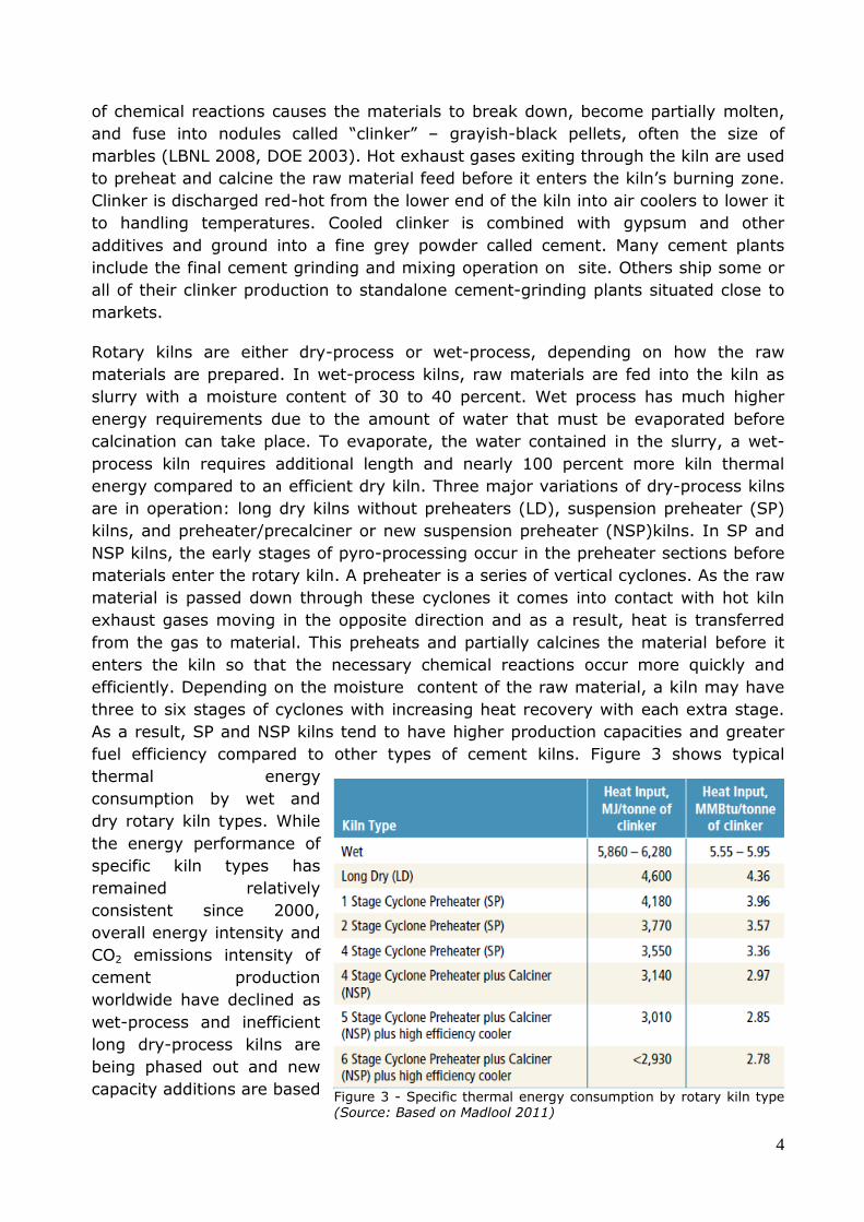
fuel efficiency compared to other types of cement kilns. Figure 3 shows typical
thermal energy
consumption by wet and
dry rotary kiln types. While
the energy performance of
specific kiln types has
remained relatively
consistent since 2000,
overall energy intensity and
CO2 emissions intensity of
cement production
worldwide have declined as
wet-process and inefficient
long dry-process kilns are
being phased out and new
capacity additions are based Figure 3 - Specific thermal energy consumption by rotary kiln type (Source: Based on Madlool 2011)
5
on more efficient SP and NSP kilns. A
global database, “Getting the Numbers
Right” (GNR), tracks historical CO2
emissions and energy consumption from
cement production facilities collected
through the CSI CO2 Protocol; it includes
aggregate data that provide a sound
analytical base for cement manufacturers
and policymakers. The most recent data
—2011—cover 967 facilities producing
over 665 million tonnes of clinker
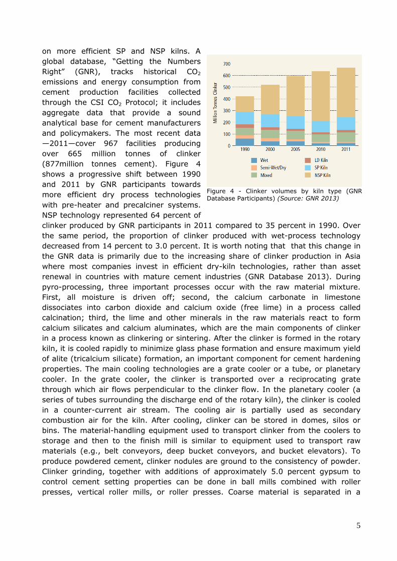
(877million tonnes cement). Figure 4
shows a progressive shift between 1990
and 2011 by GNR participants towards
more efficient dry process technologies
with pre-heater and precalciner systems.
NSP technology represented 64 percent of
clinker produced by GNR participants in 2011 compared to 35 percent in 1990. Over
the same period, the proportion of clinker produced with wet-process technology
decreased from 14 percent to 3.0 percent. It is worth noting that that this change in
the GNR data is primarily due to the increasing share of clinker production in Asia
where most companies invest in efficient dry-kiln technologies, rather than asset
renewal in countries with mature cement industries (GNR Database 2013). During
pyro-processing, three important processes occur with the raw material mixture.
First, all moisture is driven off; second, the calcium carbonate in limestone
dissociates into carbon dioxide and calcium oxide (free lime) in a process called
calcination; third, the lime and other minerals in the raw materials react to form
calcium silicates and calcium aluminates, which are the main components of clinker
in a process known as clinkering or sintering. After the clinker is formed in the rotary
kiln, it is cooled rapidly to minimize glass phase formation and ensure maximum yield
of alite (tricalcium silicate) formation, an important component for cement hardening
properties. The main cooling technologies are a grate cooler or a tube, or planetary
cooler. In the grate cooler, the clinker is transported over a reciprocating grate
through which air flows perpendicular to the clinker flow. In the planetary cooler (a
series of tubes surrounding the discharge end of the rotary kiln), the clinker is cooled
in a counter-current air stream. The cooling air is partially used as secondary
combustion air for the kiln. After cooling, clinker can be stored in domes, silos or
bins. The material-handling equipment used to transport clinker from the coolers to
storage and then to the finish mill is similar to equipment used to transport raw
materials (e.g., belt conveyors, deep bucket conveyors, and bucket elevators). To
produce powdered cement, clinker nodules are ground to the consistency of powder.
Clinker grinding, together with additions of approximately 5.0 percent gypsum to
control cement setting properties can be done in ball mills combined with roller
presses, vertical roller mills, or roller presses. Coarse material is separated in a
Figure 4 - Clinker volumes by kiln type (GNR Database Participants) (Source: GNR 2013)
6
classifier, recirculated and returned to the mill for additional grinding to ensure the
final product has uniform surface area (LBNL 2008).
3 - Waste Heat Recovery in the Cement Process
State-of-the-art new suspension process (NSP) kilns include multi-stage preheaters
and pre-calciners to pre-process raw materials before they enter the kiln, and an air-
quench system to cool the clinker product. Kiln exhaust streams, from the clinker
cooler and the kiln preheater system, contain useful thermal energy that can be
converted into power. Typically, the clinker coolers release large amounts of heated
air at 250 to 340 °C (480 to 645 °F) directly into the atmosphere (that part which is
not used as secondary combustion air for the kiln). At the kiln charging side, the 300
to 400 °C (570 to 750 °F) kiln gas coming off the preheaters is typically used to dry
material in the raw mill and/or the coal mill and then sent to electrostatic
precipitators or bag filter houses to remove dust, before finally being vented to the
atmosphere. If the raw mill was down, the exhaust gas would be cooled with a water
spray or cold air before it entered the dust collectors. Maximizing overall kiln process
efficiency is paramount for efficient plant operation. Yet, the remaining waste heat
from the preheater exhausts and clinker coolers can be recovered and used to
provide low temperature heating needs in the plant, or used to generate power to
offset a portion of power purchased from the grid, or captive power generated by fuel
consumption at the site. Typically, cement plants do not have significant low-
temperature heating requirements, so most of waste heat recovery projects have
been for power generation. The amount of waste heat available for recovery depends
on kiln system design and production, the moisture content of the raw materials and
the amount of heat required for drying in the raw mill system, solid fuel system and
cement mill. Waste heat recovery can provide up to 30 percent of a cement plant’s
overall electricity needs and offers the following advantages (LBNL 2008, EPA 2010):
• Reduces purchased power consumption (or reduces reliance on captive power
plants), which in turn reduces operating costs
• Mitigates the impact of future electric price increases
• Enhances plant power reliability
• Improves plant competitive position in the market
• Lowers plant specific energy consumption, reducing greenhouse gas emissions
(based on credit for reduced central station power generation or reduced
fossil-fired captive power generation at the cement plant).
3.1 - Waste Heat Recovery with Power Generation Systems
Waste heat recovery power systems used for cement kilns operate on the Rankine
Cycle3. This thermodynamic cycle is the basis for conventional thermal power
generating stations and consists of a heat source (boiler) that converts a liquid
working fluid to high-pressure vapour (steam, in a power station) that is then
3 The Rankine cycle is a thermodynamic cycle that converts heat into work. Central station power plants that generate electricity through a high-pressure steam turbine are based on the Rankine cycle.

7
expanded through a turbogenerator producing power. Low-pressure vapour
exhausted from the turbogenerator is condensed back to a liquid state, with
condensate from the condenser returned to the boiler feedwater pump to continue
the cycle. Waste heat recovery systems consist of heat exchangers or heat recovery
steam generators (HRSGs) that transfer heat from the exhaust gases to the working
fluid inside, turbines, electric generators, condensers and a working fluid cooling
system. Three primary waste heat recovery power generation systems are available,
differentiated by the type of working fluid (Gibbon 2013, EPA 2012, CII 2009), as
follows:
Steam Rankine Cycle (SRC) –
The most commonly used
Rankine cycle system for waste
heat recovery power generation
uses water as the working fluid
and involves generating steam
in a waste heat boiler, which
then drives a steam turbine.
Steam turbines are one of the
oldest and most versatile power
generation technologies in use.
As shown in Figure 5, in the
steam waste heat recovery
steam cycle, the working fluid—
water—is firstly pumped to
elevated pressure before entering a waste heat recovery boiler. The water is
vaporized into high-pressure steam by the hot exhaust gas from the process and
then expanded to lower temperature and pressure in a turbine, generating
mechanical power that drives an electric generator. The low-pressure steam is then
exhausted to a condenser at vacuum conditions, where the expanded vapour is
condensed to low-pressure liquid and returned to the feedwater pump and boiler.
So far, Steam cycles are the most common waste heat recovery systems in operation
in cement plants, and generally reflect the following characteristics:
Most familiar to the cement industry and are generally economically preferable
where source heat temperature exceeds 300 °C (570 °F);
Based on proven technologies and generally simple to operate;
• Widely available from a variety of suppliers;
Have generally lower installation costs than other Rankine cycle systems on a
specific cost basis (€/kW);
Need higher-temperature waste heat to operate optimally (minimum >260 °C
(500 °F)—generation efficiencies fall significantly at lower temperatures, and
lower pressure and temperature steam conditions can result in partially
condensed steam exiting the turbine, causing blade erosion;
Figure 5 - WHR system on NSP cement kiln (Source: adapted from Holcim 2012, 2013)

8
Often recover heat from the middle of the air cooler exhaust flow to increase
waste gas temperatures to an acceptable level for the system, but at the
expense of not recovering a portion of cooler waste heat;
Often require a full-time operator, depending on local regulations;
• Require feedwater conditioning systems;
• Generally require a water-cooled condenser. Air cooled condensers can be
used but create a performance penalty due to higher condenser vacuum
pressures;
• In general, they match well with large kilns and systems with low raw material
water content (resulting in higher waste gas temperatures).
Organic Rankine Cycles (ORC) – Other types of working fluids with better
generation efficiencies at lower heat source temperatures are used in organic
Rankine cycle (ORC) systems. The ORCs typically use a high molecular mass organic
working fluid such as butane or pentane that have a lower boiling point, higher
vapour pressure, higher molecular mass and higher mass flow compared to water.
Together, these features enable higher turbine efficiencies than those offered by a
steam system. The ORC systems can be utilized for waste heat sources as low as 150
°C (300 °F), whereas steam systems are limited to heat sources greater than 260 °C
(500 °F). The ORC systems are typically designed with two heat transfer stages. The
first stage transfers heat from the waste gases to an intermediate heat transfer fluid
(e.g., thermal transfer oil). The second stage transfers heat from the intermediate
heat transfer fluid to the organic working fluid. The ORCs have commonly been used
to generate power in geothermal power plants, and more recently, in pipeline
compressor heat recovery applications in the United States. The ORC systems have
been widely used to generate power from biomass systems in Europe. A few ORC
systems have been installed on cement kilns. The ORC’s specific features include the
following (Turboden 2012, Holcim2011, Ormat 2012, Gibbon 2013):
• Can recover heat from gases at lower temperatures compared to conventional
steam systems, enabling ORCs using all recoverable heat from the air cooler;
• Operate with condensing systems above atmospheric pressure, reducing risk of
air leakage into the system and eliminating the need for a de-aerator;
• Not susceptible to freezing;
• As ORCs operate at relatively low pressure, they can operate unattended and
fully automated in many locations depending on local regulations;
• The organic fluid properties result in the working fluid remaining dry (no partial
condensation) throughout the turbine, avoiding blade erosion;
• Lower-speed (rpm) ORC turbine allows generator direct drive without the need
for and inefficiency of a reduction gear;
• ORC equipment (turbines, piping, condensers, heat exchanger surface) is
typically smaller than those required for steam systems, and the turbine
generally consists of fewer stages;
• Although ORCs can provide generation efficiencies comparable to a steam
Rankine system, ORCs are typically applied to lower temperature exhaust

9
streams, limited in sizing and scalability and generally are smaller in capacity
that steam systems;
• Depending on the application, ORC systems often have a higher specific cost
(€/kW) than steam systems;
• The two-stage heat transfer process creates some system inefficiencies;
• The heat transfer fluids and organic fluids normally used in ORCs are
combustible, requiring fire protection measures and periodic replacement over
time. Moreover, there may be environmental concerns over potential system
leaks;
• In general, ORC systems are well-matched with small- to medium-size, high-
efficiency kilns or kilns with elevate draw material moisture content.
The Kalina Cycle is another Rankine cycle that uses a binary mixture of water and
ammonia as the working fluid, which allows a more efficient energy extraction from
the heat source. The Kalina cycle takes advantage of the ability of ammonia-water
mixtures to utilize variable and lower temperature heat sources. The Kalina cycle has
an operating temperature range that can accept waste heat at temperatures of 95 °C
(200 °F) to 535 °C (1,000 °F) and is claimed to be 15 to 25 percent more efficient
than ORCs at the same temperature level. The Kalina cycle is in market introduction,
with a total of nine operating systems in diverse industries such as steel and refining,
and in geothermal power plants where the hot fluid is very often a liquid below 150
°C (300 °F)4. Kalina cycle systems are now being piloted in the cement industry5.
Key features of the Kalina cycle include the following (Gibbon 2013, Mirolli 2012):
• Can be used in lower temperature applications than conventional steam
Rankine cycle systems;
• Highly flexible; the system has a high turn-down ratio and fast response to
changes in heat source temperature and flow;
• The ammonia-water mixture can be controlled to achieve improved heat
transfer and higher efficiency by matching waste heat temperatures and flows;
• The binary working fluid is non-flammable;
• The technology is in the early stage of market introduction with limited
suppliers and experience;
• In general, a Kalina cycle system is more complex and more expensive than an
ORC system.
4 An ORC or Kalina cycle operating with a liquid waste heat source can be designed around lower temperatures than one based on a gaseous heat source, such as industrial process flue gases. The minimum liquid waste temperature for economically feasible operation is 95°C (200°F). 5 FLS midth has an exclusive global license for the Kalina cycle in the cement and lime industries (excluding China) and has two installations completed or under construction in cement plants: a 4.75 MW unit on a 7,500 tpd clinker line at Star Cement’s Ras Al-Khaimah plant in UAE(utilizing air cooler vent only) that was commissioned in 2013, and a8.5 MW unit on a 7,000 tpd clinker line at D.G. Khan Cement’s Khaipur plant in Pakistan (utilizing preheater and air cooler exhaust).

10
3.2 - Application of Waste Heat Recovery Power Systems in the
Cement Process
Japanese companies spearheaded the introduction of steam cycle waste heat
recovery power systems in the cement industry. In 1980, Kawasaki Heavy Industries
(KHI) put the first waste heat recovery system into operation at Sumitomo Osaka
Cement. The first major commercial system, with a capacity of 15 MW, has been in
operation since 1982 at Taiheiyo Cement’s Kumagaya plant. China installed its first
system in 1998 in partnership with a Japanese supplier. Government policies and
Clean Development Mechanism (CDM)incentives began to drive the market in China,
and by 2012 over 700 units were operating in that country (One Stone Research
2013). The bulk of market activity today is in Asia; Chinese companies or joint
ventures are the primary suppliers. The leading manufacturers of waste heat
recovery systems using conventional steam circuit technology are now marketing
second generation systems with higher supercritical steam parameters and improved
efficiencies that reach output levels as high as 45 kWh/t of clinker.
In a typical waste heat recovery system installation on an NSP kiln (Figure 5), waste
heat boilers are installed on the hot exhaust streams exiting the preheaters (NSP-
Preheater) and air quench clinker cooler (AQC) to produce medium/low pressure
steam. The steam is fed into a condensing steam turbine that drives a generator to
produce power. Hot condensate from the condenser is fed back to the waste heat
boilers. The entire system consists of the PH and AQC waste heat boilers, the steam
turbine generator, and ancillary equipment such as condenser, water treatment
system, boiler feed pump and re-cooling system.
In Europe, the scenario is different and described by Best Available Technique
References (BREF) for cement industry. Compared to developing countries, usually
EU cement plants are smaller and more efficient because of the process type - 98%
is dry process - and the number of cyclones of the raw material pre-heating system –
3 up to 5 cyclones. However, there are more than 250 cement plants and the
theoretical ORC potential has been estimated in more than 570 MWe.
These features make WHR with steam technology less convenient due to the difficulty
of generate steam at high pressure and high temperature. In this context, WHR with
ORC technology has been implemented successfully in the last ten years.
The first Organic Rankine Cycle used in a cement plant is located in Lengfurt in
Germany. It recovers low temperature waste heat from the clinker cooler for
generating power. This technique is essentially based on the use of an organic motive
medium (pentane). Results have shown that 1.1 MW electrical power can be
generated with the given mode of operation. The achieved availability was 97% of
the operation time of the cement kiln. The clinker cooler has a waste heat output via
the clinker cooler exhaust air of 14 MW and an exhaust gas temperature of between
300–350°C of which approx. 9 MW on average is extracted. This ORC technique at

11
Lengfurt cement plant has been operating well for about 10 years. ORC heat recovery
plants already in operation are reported in Table 1.
Table 1 - ORC WHR plants in operation
Year Cement Plant ORC
Manufacturer
ORC gross power
[MW]
1999 Heidelberg Zement, Germany Ormat 1.2
2010 Italcementi - Ciment du Maroc, Morocco Turboden 2
2012 Holcim Romania Turboden 4
2013 Jura Cement, Switzerland ABB 2
2014 Holcim Slovakia Turboden 5
Ormat Incorporated, a leading ORC supplier for geothermal applications, has two
ORC systems operating in cement plants: one installed in 1999 at the Heidelberg
Cement plant in Lengfurt (Germany) and the second ORC system is a 4.8 MW unit
located at AP Cement (now Ultra Tech Cement), Tadipatri, Andhra Pradesh, India.
Turboden (acquired by Mitsubishi in 2013) installed its first cement industry ORCs
system (2 MW) at Italcementi’s Ait Baha plant in Morocco in 2010 (5,000 tpd clinker
line). In 2012,Turboden installed a 4 MW unit at a Holcim Romania plant in Alesd
(4,000 tpd clinker line); in 2014 started up a5 MW unit at a Holcim Slovakia plant in
Rohoznik (3,600tpd) and awarded a 4 MW unit at a Heidelberg Cement plant in Fieni,
Romania. ABB installed a 1.9 MW ORC system at Holcim’s Untervaz, Switzerland,
plant utilizing heat from the preheater, but no operation data have been announced.
ABB and Jura cement signed an agreement in October 2012 to install a 2.0 MW ORC
system at the Wildegg
AG plant in
Switzerland.
In the last five years
many ORC heat
recovery plants have
been starting up. A
simplified scheme of
an ORC unit installed
in a cement factory is
reported in Figure 6.
Raw materials are
preheated in multiple
cyclones, which use
exhausted gases
coming from the
rotary kiln. Thermal
energy of these Figure 6 - Heat recovery system with ORC technology in the cement industry typical layout(Source: Turboden)

12
gases (300÷450 °C) can be recovered by means of a heat exchanger (1 in Figure 6).
After being cooked in rotary kiln at 1,200 °C, the clinker has to be cooled. The
second heat source is represented by gases coming from this clinker cooler (300 °C)
that are recovered by another heat exchanger (2). Usually heat exchangers work
with diathermic oil which maintains temperature at a stable value. Then heat is
exchanged from diathermic oil to organic fluid and electricity is generated by ORC
unit.

13
4 – Focus on the WHR system of the Holcim Romania
cement plant in Aleşd: performance analysis and CO2
emissions saved
The Holcim cement plant is situated in Aleşd, a town in the Bihor County, western
Romania. It operates a modern calciner kiln with a two-string, four-stage preheater
and a clinker capacity of 1,300,000 tons per year. The Waste Heat Recovery system
consists of two kinds of heat exchangers: there are two cross-flow boilers that
recover heat from exhaust gases that exit from the pre-heater (roughly 70 % of the
thermal eat input to the ORC unit) and one that recovers heat from hot air of the
clinker cooler (it contributes to 30 % of the total heat input). The layout is similar to
the typical one represented in Figure 6. There are different thermal carriers in the
two heat recovery loops: thermal oil for the pre-heater exchangers and pressurized
water for the clinker cooler exchanger; this hybrid solution is a new and innovative
choice for the WHR systems in the cement industry. Wet cooling towers form the
heat dissipation system. The recovered energy feed an ORC unit that generates 3.7
MW of electric power. Figure 7 serves as a schematic illustration of the ORC unit
arrangement.
Figure 7 - ORC unit layout in the Aleşd plant(Source: Turboden)

14
Since its installation, the ORC system has been monitored minute-by-minute. The
main parameters, essential in order to assess the conditions and the performances of
the system, have been collected. Among all data, the most interesting parameters to
evaluate the efficiency of the whole ORC system refer to the features of the thermal
oil that goes into the evaporator and of the pressurized water entering the split
system, the status of the output fluids, the ORC power output and the auxiliaries
power consumption.
Regarding the inlet fluids, the mass flow and the temperature are the most
interesting parameters. as regards the flows coming out from the ORC group, it is
necessary to know the temperature. Finally, it is indispensable to measure the power
output at the generator’s clamps.
Thus both gross efficiency and net efficiency6 are found through the formulas:
Where:
Pgen is the measured gross electrical power generated by the ORC system;
Paux is the measured electrical power absorbed by the auxiliaries;
Qin is the thermal power input of the ORC system, supplied by thermal oil and
pressurized water, and is calculated by the following expression, obtained by a simple
energy balance on the ORC unit:
Where Qcond is the thermal power transferred to the condenser. This operation allows
to find the thermal power input through the output data, corrected taking into
account the energy losses, instead of through the input data (e.g. the mass flow of
the inlet oil and the inlet water) that are affected by a greater error.
The values used for the efficiency calculation are averaged values on the time lapse
considered.
Design data are compared to historical data referring to one operating day, precisely
the 14/10/2014. Data are collected in the Table 2 below.
6 The net efficiency is calculated taking into account only the power adsorbed by the ORC auxiliaries. It doesn’t
consider the thermal losses and the external auxiliaries, such as thermal oil pumps, off-gas fans, etc.

15
Table 2 - Design and historical data of ORC unit at Aleşd plant
Design data 14th October 2014 (24 hrs)
Primary heat sources Exhaust gases @ 360 °C and hot air @ 250 °C
ORC heat sources Thermal oil and pressurized water
Thermal oil temperature 280 / 180 °C 277 / 175 °C
Pressurized water temperature 190 / 87 °C 159 / 94 °C
Cooling water temperature 22 / 53 °C 25 / 56 °C
Total thermal power input 20,630 kW 19,200 kW
Gross electric power 3,700 kW 3,680 kW
Net electric power 3,510 kW 3,520 kW
Gross electrical efficiency 17.9 % 19.0 %
Net electrical efficiency 17.0 % 18.1 %
The good performances of the system are highlighted, in a continuous-working day
example (the net electrical efficiency takes into account only the auxiliaries
consumption of the ORC system).
Regarding the CO2 saved emissions, the
on-site electric power generation allows
to avoid discharging a large quantity of
indirect CO2 emissions into the
atmosphere : in fact these would be
emitted by the traditional power
generation systems. Considering 8,000
operating hours per year of the plant, the
net energy generation amounts to about
28,000 MWh. The Romanian electricity
generation structure in 2010 is illustrated
in Figure 8. The share of fossil fuels used
for the electricity generation accounts for
47.3 % of which 34.1 % from solid fuels,
1.1 % from crude oil and petroleum
products and 12.1 % from natural gas. According to IEA assessments, the fuel-based
CO2 electricity emission factor for Romania is 0.414 CO2 tons per MWh.
Therefore, the ORC unit in the Aleşd plant allows a CO2 indirect emissions reduction
up to 11,600 tons representing about 15 % of the total indirect emissions due to the
electric power imported. By considering also the emission factor for the clinker
production using dry process, the emission reduction amounts to about 1 %of the
total CO2 emissions (0.84 tCO2 per ton of clinker produced [2]).
Figure 8 - Gross electricity generation as % of TWh (total 60.62TWh) - 2010 (Source: Eurostat)
16
5 – Further developments
Traditional ORC based heat recovery systems employ indirect heat recovery loops
(made of thermal oil, pressurized water and/or saturated steam, etc.) to transfer the
sensible heat from the hot gases to the ORC working fluid. Direct heat exchange
solution between the hot gases and the ORC working fluid will improve the
effectiveness of the heat recovery solution and its cost by avoiding the intermediate
heat recovery loop, with the removal of the pumps, heat exchangers and all other
added cost and complexity and eliminating the losses associated with the loop.
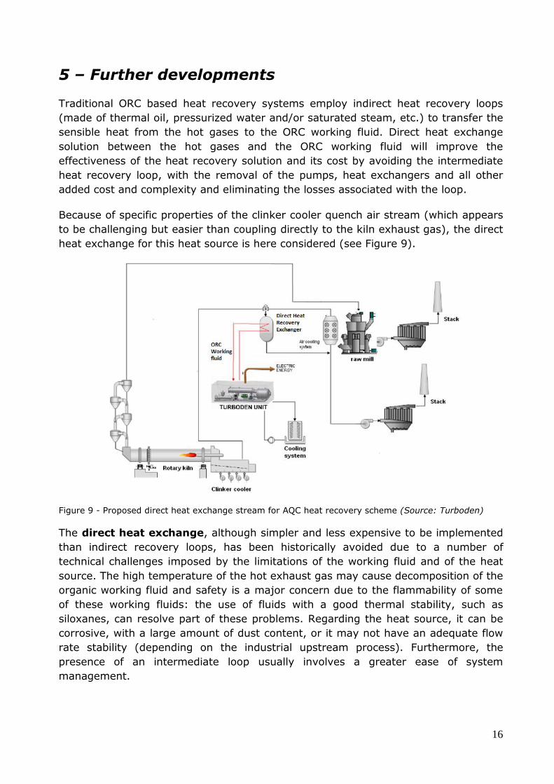
Because of specific properties of the clinker cooler quench air stream (which appears
to be challenging but easier than coupling directly to the kiln exhaust gas), the direct
heat exchange for this heat source is here considered (see Figure 9).
Figure 9 - Proposed direct heat exchange stream for AQC heat recovery scheme (Source: Turboden)
The direct heat exchange, although simpler and less expensive to be implemented
than indirect recovery loops, has been historically avoided due to a number of
technical challenges imposed by the limitations of the working fluid and of the heat
source. The high temperature of the hot exhaust gas may cause decomposition of the
organic working fluid and safety is a major concern due to the flammability of some
of these working fluids: the use of fluids with a good thermal stability, such as
siloxanes, can resolve part of these problems. Regarding the heat source, it can be
corrosive, with a large amount of dust content, or it may not have an adequate flow
rate stability (depending on the industrial upstream process). Furthermore, the
presence of an intermediate loop usually involves a greater ease of system
management.

17
Major peculiarities of AQC were recognized as: high dust content (up to 50 g/Nm3),
abrasiveness of the dust, high load variation in peak operation (up to 50% load
variation in 30 minutes), high inlet temperature in peak operation (up to + 200 °C in
comparison to design point) and high oxygen content (in comparison to previous
application studied for direct exchange).
The technical solutions to be studied take the following features into account:
• Dust collector upstream the exchanger (e.g. cyclones)
• Sacrificial tubes before the exchange bundles (to monitor erosion)
• Inspection doors for ease system inspection
• Increased tubes thickness
• By-pass leg (to mitigate fast load variation op.)
• Dilution air intake system (to mitigate fast temperature increase in peak op.)
• Optimization of suitable control system
The concept of an ORC based «Once-Through» evaporator can be described as
follow: the working fluid is fed from the bottom of the exchanger going upward,
being pre-heated, vaporized and superheated exchanging heat with the hot AQC
stream fed from the top of the exchanger going downward (counter-current
exchange profile).
6 –Conclusion
Waste heat recovery in cement industry has been described in this document.
There are over 850 waste heat recovery power installations in the world. China leads
in the number of WHR installations, 739, that employ Steam Rankine Cycle solutions,
because of the big size of the plants and their low efficiency. Regulatory measures
and lower capital costs have also been key factors behind China’s success in
mainstreaming WHR technology. As a consequence, the Chinese have become
leaders in “big size” heat to power recovery plants and are now ready to export their
technology to foreign markets.
“Small size” heat-to-power recovery plants (equipped with ORC systems), a
peculiarity of the European industrial ones, addressed to revamping the old existing
manufacturers plants, are at an early stage with less than 10 existing WHR plants.
The potential is significant, amounting to an energy recovery up to 4,592 GWh per
year, with 1,940,000 CO2 tons of emissions avoided and 416 million euro of cost
savings, assuming 8,000 operating hours per year [6]. A good reference is the Heat
Recovery in Energy Intensive Industries (H-REII) project. In addition , the EU’s
Energy Efficiency Directive could be an important driver to further exploit the
potential in Europe. As this paper has shown, the ORC references are consistent with

18
expectations, going even beyond them. Finally, it is important to note that the
installation of waste heat recovery systems allows to avoid a substantial amount of
indirect pollutant emissions, such as carbon dioxide.
7 - References
[1] IFC - IIP,Waste Heat Recovery Report for the Cement Sector: Market and
supplier analysis, June 2014
[2] F. Schorcht, I. Kourti, B.M. Scalet, S. Roudier, L.D. Sancho, Best Available
Techniques (BAT) Reference Document for the Production of Cement, Lime and
Magnesium Oxide, Industrial Emissions Directive 2010/75/EU, 2013
[3] WBCSD, CO2 and Energy Accounting and Reporting Standard for the Cement
Industry, The Cement CO2 and Energy Protocol, May 2011
[4] Eurostat, Energy, transport and environment indicators, 2012
[5] International Energy Agency, CO2 Emissions from Fuel Combustion, 2011
[6] F. Campana et al., ORC waste heat recovery in European energy intensive
industries: Energy and GHG savings, 2013