d2ne1300sg sw manual nemo - dp precision,...
TRANSCRIPT

SOFTWARE MANUALVERSION 1.3

- 2 -
- 3 -
INDEXPAGE 4PAGE 5PAGE 5PAGE 5PAGE 6PAGE 8PAGE 9
PAGE 10PAGE 11PAGE 12PAGE 13PAGE 14PAGE 30PAGE 33PAGE 43PAGE 44PAGE 45PAGE 46PAGE 49PAGE 50PAGE 57PAGE 61PAGE 62PAGE 65PAGE 69PAGE 70PAGE 70PAGE 71
1 PROGRAM TREE...........................................................................2 INTRODUCTION.............................................................................. 2.1 OPERATING LIMITS................................................................... 2.2 COMMAND BAR...................................................................... 2.3 USER INTERFACE..................................................................... 2.4 VIRTUAL KEYBOARDS................................................................
2.5 SCREEN SAVER.......................................................................3 HOME PAGE..................................................................................4 LOGIN.............................................................................................5 SETTINGS.......................................................................................
5.1 HARDWARE SETTINGS................................................. 5.1.1 MEASURE DEVICES....................................... 5.1.2 DIGITAL I/O...............................................
5.2 GLOBAL SETUP.........................................................5.3 LANGUAGE...............................................................5.4 INFO......................................................................
5.5 BACKUP/RESTORE..................................................... 5.6 NETWORK................................................................6 PROGRAMMING............................................................................
6.1 PART PROGRAMS......................................................6.2 MASTER SET............................................................
7 MEASURE.......................................................................................7.1 MEASURE................................................................
7.2 BATCHES.................................................................8 SERVICE......................................................................................... 8.1 TRANSDUCERS VIEW.................................................. 8.2 I/O LINES MAP......................................................... 8.3 LIVE MEASURE..........................................................

- 4 -
1 PROGRAM TREE
LOGIN
PAGE 11
SERVICE
PAGE 69
MEASURE
PAGE 62
SETTINGS
PAGE 12
PROGRAMMING
PAGE 49
LIVE MEASURE
PAGE 71
I/O LINES MAP
PAGE 70
MEASURE
PAGE 62
BATCHES
PAGE 65
PART PROGRAMS
PAGE 50
MASTER SET
PAGE 57
HW SETTINGS
PAGE 13
BACKUPRESTORE
PAGE 45
INFO
PAGE 44
LANGUAGE
PAGE 43
GLOBAL SETUP
PAGE 33
MEASURE DEVICES
PAGE 14
DIGITAL I/O
PAGE 30
TRANSDUCERS VIEW
PAGE 70
NETWORK
PAGE 46

- 5 -
2 INTRODUCTION
Maximum number of sensors/transducers 8
Maximum number of characteristics 4
Maximum number of auxiliary characteristics 4
Maximum number of part programs 40
Maximum number of steps 8
Maximum number of batches 40
Maximum number of classes 32
2.1 Operating limits
Nemo, compact, robust and reliable professional gage computer offers features that enable you to perform simple measurement applications intuitively and rapidly.Nemo is capable of acquiring data from traditional wired and wireless measurement devices, then the data locally or uploading the data to a LAN network in real time. The 5.7”TFT colour display guarantees that the measurements are easy to read, for your operators and the touch screen enables them to carry out programming operations (password protected) and acquire data, without the need for external input devices. The embedded architecture based on “RISC Processor Technology” with the built in Secure Digital micro card provides powerful memory capacity.An important function of the Nemo, when a system crash happens, it saves a .logfile with the complete backup of the Nemo. In that way, it is possible to recover and analyze the situation just before the system crash.
A command bar containing a series of buttons corresponding to the selected menu is always displayed in the upper part of the screen, each button includes a brief description, keeping on tapping on any button you can read a more detailed description of the command associated.
2.2 Command bar

- 6 -
The user interface is a touch-screen, so it is necessary to tap the buttons and fields to interact with the Nemo software, alternatively, it is possible to connect a USB type mouse to navigate the screen easily.
HOME: to return to HOME PAGE
BACK: to return to upper level
2.3 User interface
OK: appears on all windows programming, tap this button to exit and save the data
CANCEL: appears on all windows programming, tap this button to exit without save the data
SCROLL UP: tap this button to scroll towards the top of the current page in order to display the elements that would otherwise be outside the limits of the screen
SCROLL DOWN: tap this button to scroll towards the bottom of the current page in order to display the elements that would otherwise be outside the limits of the screen
SCROLL LEFT: tap this button to scroll towards the left of the current page in order to display the elements that would otherwise be outside the limits of the screen
SCROLL RIGHT: tap this button to scroll towards the right of the current page in order to display the elements that would otherwise be outside the limits of the screen
Note: The HOME and BACK buttons are always present on the superior bar; they are enabled and you get back to the home page or the previous page displayed, tapping them

- 7 -
NEW: tap this button to create a new element on the current page
SELECT: tap this button to select various elements on the current page
COPY: tap this button to copy one or more element on the current page
DELETE: tap this button to delete one or more element on the current page
EDIT: tap this button to modify one or more element on the current page
PREVIOUS PAGE: tap this button to view the previous page
NEXT PAGE: tap this button to view the next page

- 8 -
The operator can enter data through by a virtual keyboards that vary in their formatdepending on the language and type of data to be entered or modified.Tap OK button to confirm the data that have been entered.
2.4 Virtual keyboards
Tap this button to view the below page, where it is possible to switch from alphabetic to numerical mode, and vice versa.
Note: It is also possible to connect a USB keyboard to Nemo, or a laser scanner (for reading barcodes or datamatrix codes) if it is configured in wedge emulation. To guarantee a correct functionality of those devices we suggest to connect it before the Nemo startup.

- 9 -
Note: In order to avoid any trouble, on the display, about the persistence of a static image, it is strongly suggest to enable the screen saver mode
It is possible to set up the screen saver from the GLOBAL SETUP menu.If the Nemo screen is not tapped for a preset period, the following screen is displayed.
2.5 Screen saver
Tapping on the screen to the last page will be shown.Before setting the screen saver, you have to set the Standby parameters.

- 10 -
The menu provides access to all functions of the software.
Access to MEASURE page
User switching between ADMINISTRATOR and OPERATOR
Access to PROGRAMMING menu
Access to SETTINGS menu
Access to SERVICE menu
3 HOME PAGE

- 11 -
In this section you can decide whether to enter the program with ADMINISTRATOR or OPERATOR rights.
In order to access all the program functions, the user must log in as Administrator since Operator level users cannot access certain parts of the program, for example, in the section dedicated to the part programs, operators can view the existing programs, but cannot modify the parameters or create new part programs, they can, however, create batches and associate them with the existing part programs. Operators may also view the devices connected to Nemo, but may not modify their settings.
4 LOGIN
Tap this button in HOME PAGE to enter in LOGIN menu.

- 12 -
5 SETTINGS
In this section you can configure several parameters to meet your needs.
Access to HARDWARE SETTINGS menu
Access to GLOBAL SETUP menu
Change the LANGUAGE
Access to INFO about the Nemo software version and other information
Tap this button in HOME PAGE to enter in SETTINGS menu.
- 13 -
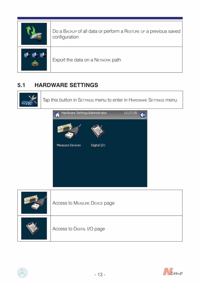
5.1 HARDWARE SETTINGS
Access to MEASURE DEVICE page
Access to DIGITAL I/O page
Tap this button in SETTINGS menu to enter in HARDWARE SETTINGS menu.
Do a BACKUP of all data or perform a RESTORE OF a previous saved configuration
Export the data on a NETWORK path

- 14 -
5.1.1 MEASURE DEVICE
Tap this button in HARDWARE SETTINGS menu to enter in MEASURE DEVICE page.
The MEASURE DEVICES page displays the devices connected to Nemo and the transducers connected to them.
The following is a list of the devices that can be connected to Nemo.• M1 Wave: Marposs Bluetooth® bore gauges with electrical plugs.• M2 Wave: Marposs Bluetooth® snap with electrical plugs.• I-Wave: Marposs Bluetooth® bore gauges with mechanical plugs.• MultiWave: Marposs multisection bore gauges with Bluetooth® interface. Manages up to 7 measurement channels, excluding the optional heat sensor (i.e. a maximum of 6 channels if the system is also fitted with the heat sensor).• Easy Box U1AIR: 1 pneumatic input.• Easy Box U3AIR: 3 pneumatic inputs.• Easy Box U4AIR: 4 pneumatic inputs.• Easy Box U4H: 4 Marposs standard half-bridge/HBT transducers.• Easy Box U4D: 4 Mitutoyo Digimatic compatible transducers.• Easy Box U4T: 4 half-bridge/HBT compatible with Tesa amplifiers.• Easy Box U4F: 4 Marposs standard full-bridge/LVDT transducers.• Easy Box U8IO: 8 digital Input/Output.• Easy Box U4P: push button for remote control and data acquisition.• Easy Box U4M: “MG” 4 HBT transducers interface.• Easy Box U4TP_E: for type-E thermocouples.• Easy Box U4TP_J: for type-J thermocouples.• Easy Box U4TP_K: for type-K thermocouples.• Easy Box U4TE: for “Trac” tranducers.

- 15 -
• Easy Box U4E: 3 inputs for incremental transducers.• Easy Box U4F-HR: 4 Marposs standard full-bridge/LVDT transducers withsub-micron resolution.• Digi Crown: Marposs digital network for connecting various devices
Digi Crown_1LVDT Digi Crown_2LVDT Digi Crown_INOUT Digi Crown_INPUT Digi Crown_AN_IN Digi Crown_ANENC Digi Crown_DGENC• Red Crown 2 USB: USB pencil probe.
The following list represents the serial devices managed by Nemo.MARPOSS DEVICES:• Quick Digit: digital dial indicators with RS232 (simplex or duplex comunication protocol) or USB (duplex comunication protocol).• Quick Read: compact electronic display unit.• E4N: microprocessor column display unit.
SYLVAC DEVICES/PROTOCOLS:• Caliper Simplex• Caliper Duplex• HolematicTESA DEVICES/PROTOCOLS:• Cal IP65
The connected devices are shown in the DEVICE NAME area; the boxes arehighlighted in green if the corresponding devices are connected and programmedcorrectly, or in red if the devices are not programmed and/or connected correctly.
The transducers connected to the devices are shown in the TRANSDUCER NAME
area, the boxes are highlighted in green if the corresponding transducers areconnected and correctly programmed (the maximum number of transducers whichcan be connected is 8), red if they are connected but not programmed correctly orvice versa, and grey if they are neither connected nor programmed.
Note: We cannot guarantee the complete compatibility of the protocols developed, to comunicate with these devices, due the continuous developement performed by the manufactures of them. On demand we can develop the protocol for a new serial device only if it is provided to us. Please contact us for any other detail.

- 16 -
Tap UPDATE to update the configuration of the connected devices
When this button is tapped, the following message will be shown:
Tap YES to update the configuration, so that all the elements currently connected to Nemo are retained, and only those that are not connected will be cancelled.It is suggest to Tap this button to carry out a complete update of the connected devices. Otherwise Tap NO to update the configuration without any data retention.

- 17 -
How to connect a wireless device
1) Connect a Bluetooth® key dongle for wireless Marposs wave devices using the USB port.
2) Tap UPDATE in MEASURE DEVICE page.
3) The system recognizes that a Bluetooth® key dongle is connected, showing the following message. Tap on YES.
4) Select the wireless device then tap on OK.

- 18 -
6) Wait until the operation is carried out.
7) When the binding operation is completed, a message, described in the step 3, it is displayed. If it don’t need to connect any other wireless device, tap on NO. Now the wireless device is ready to use.
5) Tap on OK on the following message when the device is ready to be set in “DISCOVERABLE” mode, after that press the button until the led becomes red continuosly from red blinking.
- 19 -
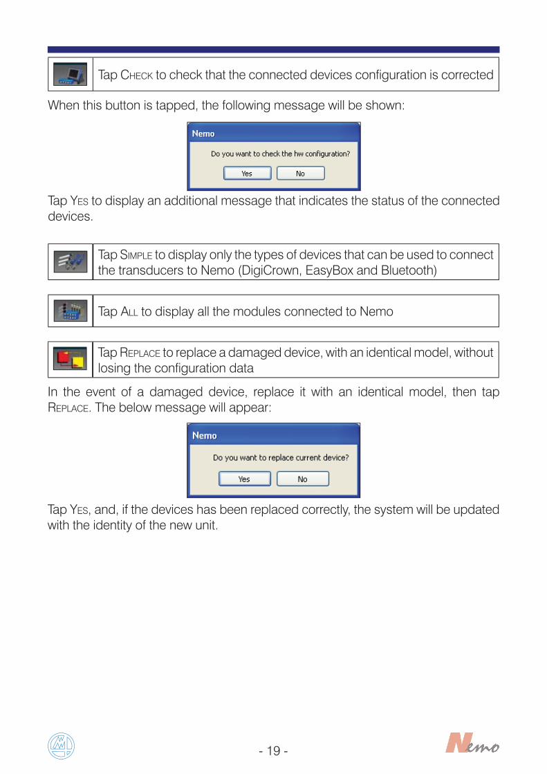
Tap CHECK to check that the connected devices configuration is corrected
When this button is tapped, the following message will be shown:
Tap YES to display an additional message that indicates the status of the connected devices.
Tap SIMPLE to display only the types of devices that can be used to connect the transducers to Nemo (DigiCrown, EasyBox and Bluetooth)
Tap ALL to display all the modules connected to Nemo
Tap REPLACE to replace a damaged device, with an identical model, without losing the configuration data
In the event of a damaged device, replace it with an identical model, then tap REPLACE. The below message will appear:
Tap YES, and, if the devices has been replaced correctly, the system will be updated with the identity of the new unit.

- 20 -
Tap TRANSDUCERS to access to the page that displays the connected transducers
The message INV indicates that the transducer doesn’t work, the number in parentheses is the error code. Below there is a list of error codes with the associated descriptions.
1 Undefined transducer 2 Uncalibrated transducer
3 Wrong Mode 4 Transducer not connected
5 HW Error Offset 6 HW Error Gain
7 Transducer not ready 8 Overrange transducer
20 HWError (Incremental)
Incremental
21 Warning Phase A 22 Warning Phase B
23 Warning Marker 24 Overspeed
25 Warning Phase Analogic 26 Synchronism Overrun
27 Warning Marker Phase A 28 Warning Marker Phase B
29 Warning Marker Phase A and B 30 Warning Phase A and B
31 No Power
Error codes greater than 20 may have different meanings, depending on the type of transducer.
Tap μM| IN to switch from meters to inches and vice versa.

- 21 -
When the field DEVICE NAME is selected, tap EDIT to modify the connected devices configuration parameters
Depending on the connected devices, different pages are shown.EASY BOX U4H
Note: The measure resolution depends on the acquisition delay value. The default value is the best trade-off between them, to get a better resolution you must set an higher value on the acquisition delay.Through that device, it isn’t allow to manage the complete range in some pencil probe models.
The following parameters are configurable:• DEVICE NAME: to enter the device name.• ACQUSITION DELAY 1÷4 [S]: to enter the acquisition delay.

- 22 -
EASY BOX U4P
EASY BOX U4E
The following parameters are configurable:• DEVICE NAME: to enter the device name.• INPUT 1÷4: NORMAL or COMMUTATIVE.
The following parameters are configurable:• DEVICE NAME: to enter the device name.• EXTERNAL POWER SUPPLY: YES OR NO.
Note: In the INPUT FIELDS is possible to choose NORMAL or COMMUTATIVE. The difference between them is based on the behavior of the programmed input bit.
Note: The EXTERNAL POWER SUPPLY must be changed to YES if it is present.

- 23 -
DIGICROWN 1/2 CH LVDT
The following parameters are configurable:• DEVICE NAME: to enter the device name.• ENABLE TEDS: enabling this function (choosing YES instead of NO), Nemo will read the retentive data written on the head of the digital pencil probe.• LINEARIZATION: this parameter gives the possibility to consider the linearization data. • PRE-TRAVEL VALUE: to enter the pre-travel value.• EXTRA-TRAVEL VALUE: to enter the extra-travel value.
The configurable parameters are the same for Digicrown 1 Ch and the Digicrown 2 Ch.
DIGICROWN AI

- 24 -
The following parameters are configurable:• DEVICE NAME: to enter the device name.• VREF: the DigiBox AI (analog input) permits to drive an output voltage (calibrated at the factory) for only voltage reference purpose (no supply). For example to measure or transducers bridge, which need a voltage reference. The value could be programmed when the Check Box is ticked.• ENABLE FILTER: the DigiBox AI (Analog Input) permits to apply a digital filter IIR LP to the analogic input measure. When the Check Box is ticked, it is possible to insert the cut-off frequency value of the LP, Low Pass filter. If the Check Box isn’t ticked, there is no filter ( maximum band and maximum noise).
BLUETOOTH DEVICE (M1 WAVE, M2 WAVE, MULTIWAVE, IWAVE)
Note: to communicate with a wave device, it is necessary to connect a dongle Bluetooth® USB and performing successfully the binding of the wave device.
The following parameters are configurable:• DEVICE NAME: to enter the device name.• ACQUISITION SPEED: SLOW (10 samples/second), MEDIUM (20 samples/second), FAST (40 samples/second).• BATTERY TYPE: LI-ION, ALKALINE.• TURN OFF TIME: to enter the turn off time.• BATTERY LEVEL: it shows the battery level.
Note: it is possible to use up to 7 wave devices simultaneously.

- 25 -
EASY BOX U8IO
Tapping ALL, Nemo will display all modules connected. This operation is required to show the following devices.
The following parameters are configurable:• DEVICE NAME: to enter the device name.• REFRESH TIME[S]: to enter the channel reading period (Minimum=0, Maximum=1).
RED CROWN2 USB
The following parameters are configurable:• DEVICE NAME: to enter the device name.

- 26 -
DIGICROWN I/O ONLY INPUT
The following parameters are configurable:• DEVICE NAME: to enter the device name.• FILTER TIME: this parameter, espressed in [ms], could set an optional filtering (only present on the modules DigiCrown I/O), based on the minimum time on staying on Low or High state of the physical input pin in order to be detected as the next effective value. There is only one parameter for all 8 input pins.
DIGICROWN I/O INPUT/OUTPUT
The following parameters are configurable:• DEVICE NAME: to enter the device name.• FILTER TIME: this parameter, espressed in [ms], could set an optional filtering (only present on the modules DigiCrown I/O), based on the minimum time of staying on Low or High state of the physical input pin in order to be detected as the next effective value. There is only one parameter for all 8 input pins.

- 27 -
DIGICROWN Y EMB.
BT DONGLE
The following parameters are configurable:• DEVICE NAME: to enter the device name.• NET BAUDRATE: to enter the net baudrate (9600/208333/625000 bit/s).
Note: the devices DigiCrown Y EMB and the BT Dongle are shown if Nemo has the DigiCrown embedded and the dongle Bluetooth® connected, they are interface devices instead acquisition devices.
• WATCHDOG: to enter the watchdog time [s].

- 28 -
Tap EDIT TRANSDUCER to modify the connected transducers configuration parameters
Note: this function may also be accessed by double-tapping on the connected transducers identification area.
• TRANSDUCER: to enter the number of transducer.• SERIAL NUMBER: to enter the serial number.• SENSOR TYPE: to enter the sensor type.• MEASURE UNIT: to enter the measure unit.• MEASURING RANGE: to show the measuring range.• APPLICATION RANGE: to enter the application range.• OFFSET: to enter an additional value at the transducer.

- 29 -
• CORRECTION: to enter a value with a meaning such as gain adjustment.• ARM RATIO: to enter a moltiplicative factor at the transducer.• SIGN INVERSION: to set the direction of the measure.
Below are shown the default value for this parameter and the direction of the measurement value, when the sensor is pushed:
DeviceMeasurement value
when sensor is PUSHED
Sign inversion
Pencil probe(LVDT - HBT)
Decreasing Yes
Wireless bore gauge(LVDT)
Decreasing No
Wireless bore gauge(HBT)
Increasing No
Pneumatic(used with U1Air, U3Air, U4Air)
Decreasing Yes

- 30 -
5.1.2 DIGITAL I/O
Tap this button in HARDWARE SETTINGS menu to enter in DIGITAL I/O page.
In order to minimize the efforts made by the user to program the device, Nemo software manages digital signals (Input and Output) using precompiled lists of signals. The operator can create the I/O layout according to his needs.For more detailed information on the I/O Layout management, please contact the nearest Marposs office.
Tap DEFAULT button to set the device functions in standard mode (ex. EasyBox/footswitch)
Input signalsThe management of the inputs occurs (unless otherwise indication) on the rising edge.• START/STOP TYPE1: the rising edge works as START, the falling edge works as STOP. The same line is used to give both commands. On rising edge the START, on falling edge the stop. This configuration is available (and cannot be changed) in all the footswitch connected to Easy Box.• START/STOP TYPE2: the first rising edge works as START, the second rising edge works as STOP. The same line is used to give both commands. START and STOP commands are active on rising edge, it means that two pushes on the button are necessary to complete an acquisition. This configuration is available (and cannot be changed) for all the M1 Wave pushbuttons. • START: the rising edge works as START. START command active on rising edge.• STOP: the rising edge works as STOP. STOP command active on rising edge.• SKIP ZERO STEP: during the zeroing cycle it reports to pass to the next step.• ZERO MODE: to go in the page where it is possible to perform the zeroing.

- 31 -
• MEAS MODE: to activate the measurement mode by batch.• BATCH SELECTION: trigger to work with the Batch code.• BATCH CODE: for example, if you program two consecutive bits with this value you will address up to 4 batch. Trying to give more details, with those two bits a code will be assigned to each batch using the binary code (00, 01, 10 or 11) and it can be associated in the batch definition page the I/O index as 1, 2, 3 or 4 respectively. After this codification setting 1 on the Batch selection field, Nemo starts working with the programmed batch. Please note that it is possible to use up to 4 bits to code the batches.• BACK STEP: to return at the previous step.• BATCH 1÷16: to direct selection of the batch.• STEP 1÷8: to direct selection of the step.
Output signals
• READY TO START: If it is high, it indicates that Nemo is ready to start a cycle (measure or zeroing). It goes low when:- Nemo is showing a programming page- During an acquisition step- The state is busy• ZERO ERR: if an error happens during the zeroing it goes high. It goes low after a well performed zeroing or exiting from zeroing procedure.• PART GOOD: the signal indicates that last gauged part is GOOD. It works at the end of the cycle; at the start of a new cycle it will be reset.• PART REJECT: the signal indicates that last gauged part is SCRAP. It works at the end of the cycle; at the start of a new cycle it will be reset.• PART REWORKABLE: the signal indicates that last gauged part is REWORKABLE. It works at the end of the cycle; at the start of a new cycle it will be reset.• PART TREND: the signal indicates that last gauged part is in TREND range. It works at the end of the cycle; at the start of a new cycle it will be reset.• BATCH ERROR: this signal indicates an error during batch selection (the addressed BATCH is not available) or measure interrupted by an error during the sensor acquisition (sensor broken, disconnected).The measurement is interrupted abnormally if one of the inputs is in over-range (programmed at sensor level) upon completion of the measurement.• CYCLE ERROR: it indicates an error on cycle.• END CYCLE: it indicates that the gauging sequence is completed. It works at the end of the cycle; at the start of a new cycle it will be reset• MEASURE STEP RUNNING: It indicates that system is gauging. The signalgoes high subsequently the START signal (beginning of measure step) and it goesdown at the end of the measure step STOP signal.• PART ZEROED: It indicates that the part, on the batch active, is zeroed. It works if the state is MEASURE or READY. If a zeroing is requested, moving on measure directly, with this signal low, it generates an error.

- 32 -
Note: the minimum time between two subsequent edges, in order to be detected by Nemo is 200 milliseconds and the minimum time for staying high the signal is 100 milliseconds.
Signal 1: Start
Signal 2: Stop
100 ms
200 ms
• PART ROTATION: It indicates that a dynamic measure step is running. It works such as the MEASURE STEP RUNNING but it is active only on the measure steps where there are dynamic measure acquisition programmed.

- 33 -
5.2 GLOBAL SETUP
In the MISCELLANOUS page, you can change the following parameters:
• PASSWORD ADMINISTRATOR: to enter the alphanumeric password for the administrator.• PASSWORD OPERATOR: to enter the alphanumeric password for the operator user.• CLASS MANAGEMENT: the possible choices are YES or NO. It is possible to manage up to 32 classes, programmable in automatic or manual way. Before managing the classes, in the part program menu, it is necessary to enable it in this menu.• STANDBY (MIN): to enter the number of minutes after which the screen goes into standby mode.• SCREENSAVER (MIN): to enter the number of minutes after which the screen saver is displayed, after going into standby mode.
Tap this button in SETTINGS menu to enter in GLOBAL SETUP pages.
Miscellanous page
Tap TIME button to change the date and/or the time

- 34 -
In the VIDEO page, you can change the following parameters:
• BARGRAPH MODE: VERTICAL, HORIZONTAL
• BARGRAPH BACKGROUND: BLACK, COLOUR
• MEAS. DISPLAY MODE: ABSOLUTE, DISPLACEMENT
• VIEW SOFTKEY TEXT: YES, NO
• BARGRAPH INDICATOR: FILLED, LED• SAMPLE NUMBER: to insert the number of SAMPLE
Video page
In the ACTIONS ON BATCH CLOSING page, you can change the following parameters to set the default options at the moment of a batch creation:
• AUTOMATIC DATA EXPORT: NO, MEASURE.
Actions on batch closing

- 35 -
In the DATA EXPORT page, you can change the following parameters:
• DATA EXPORT FORMAT: TEXT (.CSV), Q-DAS (.DFQ).• EXPORT ON USB DISK: YES, NO, ONLY IF PLUGGED.• EXPORT ON NETWORK: YES, NO, ONLY IF CONNECTED.
Data export
CSV FORMAT
FIELDS DESCRIPTION
Date and time Date and time of the measure
* Separator (for characteristic)
Short Description Name of the characteristic
Value Value of the characteristic
UoM Measure unit of the characteristic
Absolute value Absolute value of the characteristic
Abs. value UoM Measure unit of the absolute value
Nominal value Nominal value of the characteristic
UTL Value Upper tolerance value of the characteristic
LTL Value Lower tolerance value of the characteristic

- 36 -
Q-Das FORMAT
K-FIELDS DESCRIPTION
K0001 Date and time of the measure (for each characteristic)
K0002 Attribute
K0004 Time/Date
K0100 Total number of characteristics in file
K1001 Part number
K1002 Part description
K1041 Drawing Number Text
K1053 Contract
K2001 Characteristic Number
K2002 Characteristic Description
K2004 Characteristic Type
K2022 Decimal Places
K2101 Nominal Value
K2110 Lower Limit Value
K2111 Upper Limit Value
K2120 Lower Limit type
K2121 Upper Limit type
K2141 Unit
K2142 Unit Description
K2404 Gage Resolution

- 37 -
In the NETWORK page, you can change the following parameters:
• IP ADDRESS, SUBNET MASK and DOMAIN: to connect the Nemo on the network.
Entering in this page it is possible to change the IP address of the Nemo, the default IP address is 192.168.0.1.
Network
Note: the system detects automatically all the domains of the connected network .For more information see the paragraph 5.6 “NETWORK”.

- 38 -
For the time being two different serial output protocols (DOP-STD01 e DOP-STD02 the same used by the Merlin SW) are managed by Nemo.
Serial output protocol
Note: it is recommended to use these serial output protocols through EasyBox U4S.
The following description is concerning the standard data output protocol on a serial port for the Nemo software, denominated DOP-STD01.
OUTPUT MESSAGE FORMATSTART
Name Characters Meaning
Start 1 Start message character: <STX>
2 <CR><LF>GLOBAL DATA
Name Characters Meaning
Date 8 Date test was performed in “DD/MM/YY” format
Hour 8 Time test was performed in “HH:MM:SS” format
Program 20 Name of part program used
Standard protocol N°1 (DOP-STD01)

- 39 -
Serial number 20Serial number or progressive number of piece within the active batch
Piece result 2Code that indicates the result of the measurement performed on the piece: G (good), T(trend), R(eject), NV(not valid)
Number of characteristics
2Number of characteristics sent (only non auxiliary characters are sent)
2 <CR><LF>
CHARACTERISTIC DATAThe following information is sent for each characteristic
Name Characters Meaning
Name 3 Name of the characteristics.
Value 12
Absolute or relative measurement value, as displayed. The value is formatted according to the precision setup for the characteristic. The decimal separator is always represented by a point. The sign is always indicated.
Measurement unit
4 Measurement unit symbol, as displayed (μm, mm, °C…)
Result 3Code that indicates the result of the measurement performed on the single characteristic: G,T+,T-,R+,R-,NV+,NV-
2 <CR><LF>
CLOSING
Name Characters Meaning
Checksum 3
Message checksum, defined as the low byte of the sum of the ASCII codes of all the characters in the message (apart from the stop message ETX character and the final <CR> <LF>)
Stop 1 Stop message character: <ETX>
2 <CR><LF>

- 40 -
EXAMPLE OF DATA OUTPUTIn the following example, the values of two measurements (OG1 and OG2) performed on good piece number 11 using the Biella program are transferred:
<STX><CR><LF>10/01/0815:10:01biella______________11__________________G_2_<CR><LF>OG1+24.1234____μm__G__<CR><LF>OP1-12.123_____μm__G__<CR><LF>xxx<ETX><CR><LF>
Legend:<STX>: character ASCII 2<ETX>: character ASCII 3<LF>: character ASCII 10<CR>: character ASCII 13_ : ASCII space character 32xxx: indicates the value calculated for the checksum
The following description is concerning the standard data output protocol on a serial port for the Nemo software, denominated DOP-STD02.
OUTPUT MESSAGE FORMAT
START
Name Characters Meaning
Start 1 Start message character: <STX>
2 <CR><LF>GLOBAL DATA
Name Characters Meaning
Date 8 Date test was performed in “DD/MM/YY” format
Hour 8 Time test was performed in “HH:MM:SS” format
Program 20 Name of part program used
Serial number 20Serial number or progressive number of piece within the active batch
Piece result 2Code that indicates the result of the measurement performed on the piece: G (good), T(trend), R(eject), NV(not valid)
Number of characteristics
2Number of characteristics sent (only non auxiliary characters are sent)
2 <CR><LF>
Standard protocol N°2 (DOP-STD02)

- 41 -
CHARACTERISTIC DATAThe following information is sent for each characteristic
Name Characters Meaning
Name 3 Name of the characteristics.
Value 12
Absolute or relative measurement value, as displayed. The value is formatted according to the precision setup for the characteristic. The decimal separator is always represented by a point. The sign is always indicated.
Measurement unit
4Measurement unit symbol, as displayed (μm, mm, °C…)
Result 3Code that indicates the result of the measurement performed on the single characteristic: G,T+,T-,R+,R-,NV+,NV-
Class 5
Characteristic classification code, calculated on the basis of the measurement value, in accordance with the table selected during the programming phase. If the classification code is not required for the characteristic a series of space characters is sent instead.
2 <CR><LF>
CLOSING
Name Characters Meaning
Checksum 3
Message checksum, defined as the low byte of the sum of the ASCII codes of all the characters in the message (apart from the stop message ETX character and the final <CR> <LF>)
Stop 1 Stop message character: <ETX>
2 <CR><LF>

- 42 -
EXAMPLE OF DATA OUTPUT
In the following example, the values of two measurements (OG1 and OG2) performed on good piece number 11 using the Biella program are transferred. The classification for the first measurement value is 02 for the second it is 05:
<STX><CR><LF>10/01/0815:10:01biella______________11__________________G_2_<CR><LF>OG1+24.1234____μm__G__02___<CR><LF>OP1-12.123_____μm__G__05___<CR><LF>xxx<ETX><CR><LF>
Legend<STX> : character ASCII 2<ETX> : character ASCII 3<LF> : character ASCII 10<CR> : character ASCII 13_ : ASCII space character 32xxx: indicates the value calculated for the checksum
Note: the only difference between protocol DOP-STD01 and protocol DOP-STD02 is that the latter also includes the characteristic class code

- 43 -
5.3 LANGUAGE
Tap this button in SETTINGS menu to enter in LANGUAGE pages.
Available languages: English, Italian, French, German, Japanese, Spanish, Portuguese, Chinese, Dutch, Swedish, Polish, Hungarian, Czech and Korean.

- 44 -
5.4 INFO
Tap this button in SETTINGS menu to enter in INFO pages.
In this page, you can find the information about the software version.
Tap UPDATE button to update the Nemo firmware.To update the firmware, connect a USB (pen drive / flash drive / memory stick) containing the updated version of the firmware, then tap UPDATE button.
Tap RESET button to delete all the programming, getting back to the factory settings.
Tap on YES if you want to reset Nemo to factory settings, otherwise tap on NO.
- 45 -
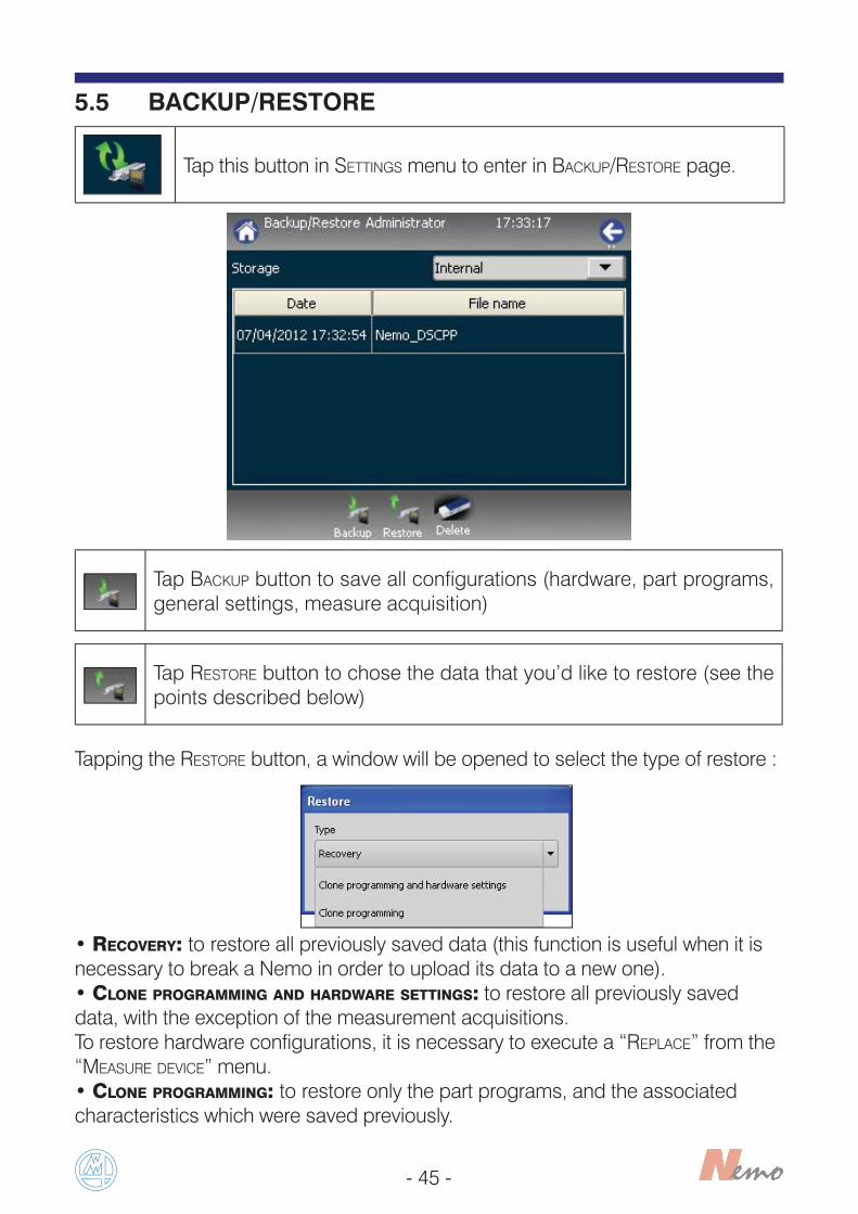
5.5 BACKUP/RESTORE
Tap this button in SETTINGS menu to enter in BACKUP/RESTORE page.
Tap BACKUP button to save all configurations (hardware, part programs, general settings, measure acquisition)
Tap RESTORE button to chose the data that you’d like to restore (see the points described below)
Tapping the RESTORE button, a window will be opened to select the type of restore :
• RECOVERY: to restore all previously saved data (this function is useful when it is necessary to break a Nemo in order to upload its data to a new one).• CLONE PROGRAMMING AND HARDWARE SETTINGS: to restore all previously saved data, with the exception of the measurement acquisitions.To restore hardware configurations, it is necessary to execute a “REPLACE” from the “MEASURE DEVICE” menu.• CLONE PROGRAMMING: to restore only the part programs, and the associated characteristics which were saved previously.

- 46 -
5.6 NETWORK
Tap this button in SETTINGS menu to enter in NETWORK page.
Tap CHECK button to verify if the connection at the REMOTE PATH (programmable in the DATA EXPORT page in GLOBAL SETUP) is possible. The field REMOTE PATH will change his colour from grey to green if the connection is possible and in red if it isn’t.
In NETWORK page, it is possible to change the following parameters:• USER and PASSWORD: to insert the credentials if they are required from the network.• DOMAIN: to show the domain previously programmed in the NETWORK page in GLOBAL SETUP.• SERVER: to select the server. • SHARE: to set the folder where the system exports the data.

- 47 -
Tap SUBDIR button to select the sub-directory where the data will be exported
At the batch closing, the data can be saved in three different mode:• The data can be exported automatically on a USB disk, setting the related parameter in the page DATA EXPORT of the GLOBAL SETUP (EXPORT ON USB=YES).• The data can be exported automatically on a network path, setting the relative parameters in the page DATA EXPORT (EXPORT ON NETWORK=YES) and NETWORK pages (IP ADDRESS, SUBNET and DOMAIN) of the GLOBAL SETUP.
Note: in this case it is necessary to create a shared folder on the connected PC (server) and if the Nemo IP address is 192.168.0.1 (default), it has to set the PC IP address on a similar way (for example 192.168.0.2).

- 48 -
• In the Nemo internal memory, there are data saved which is downloadable manually in a USB disk tapping the TRANSFER soft-key in the BATCH page or from a PC using a FTP client.In this case it is possible to explore the content of some folders, downloading any data saved related to the batches and parts gauged, using a software (like FileZilla, NotePad++, etc.) or by browser (like Internet Explorer, FireFox, Chrome, etc.) writing on the address bar “ ftp://” and the IP address, assigned to Nemo, as in the figure below:

- 49 -
6 PROGRAMMING
To enter in PART PROGRAMS menu
To enter in MASTER SET menu
Tap this button in HOME PAGE to enter in PROGRAMMING menu.

- 50 -
6.1 PART PROGRAMS
Tap this button in PROGRAMMING menu to enter in PART PROGRAMS pages. Tap NEW to create a new part program.
• NAME: name of the part to be programmed.• DESCRIPTION: description of the part to be programmed.• DRAWING NUMBER: reference DRAWING NUMBER.
The part program name may not contain characters that Microsoft® Windows® does not accept as part of file names (E.g. / \ : * ? “<>| ø...). If any of these characters is used, the system will allocate as part program name a string containing the exportation date and time (YYYYMMDDhhmmss) during the batch export phase.
Part program definition

- 51 -
Step definition
The configuration parameters are described below.• NAME: name of the step to be programmed.• DESCRIPTION: description of the measurement STEP.• MESSAGE: measurement STEP MESSAGE; this message appears in the page heading highlighted in yellow, and it can be used to provide assistance to the operator.• INITIAL DELAY (SEC): initial measurement delay setting (in sec.).• ACQUISITION TIME (SEC): data acquisition period (in sec.).
• NAME: to enter the FORMULA name.• DESCRIPTION: full description of the characteristic.
Miscellaneous page (Characteristics definition) This page is used to enter the basic CHARACTERISTIC data, i.e. name, FORMULA and tolerance limits.

- 52 -
• TYPE: to select the measurement type (options: generic, external diameter, internal diameter, external distance, internal distance, taper, ovality, barrelshape, straightness, flatness, circularity, cylindricity, parallelism, perpendicularity, angularity, position, concentricity, coaxiality, symmetry, runout, total runout).• FORMULA: the FORMULA may include TRANSDUCERS, mathematical functions or previously acquired measurements, up to a maximum of 60 characters. Tap the “T” button to select the transducers list. Tap a line to add the corresponding TRANSDUCER to the FORMULA. Tap the “M” button to select the CHARACTERISTIC list. Tap a line to ADD the corresponding CHARACTERISTIC to the FORMULA.The following mathematical and trigonometric functions are available:
SIN(): sine function COS(): cosine function
TAN(): tangent function ASIN(): arcsine function
ACOS(): arccosine function ATAN(): arctangent function
CTAN(): cotangent function SQRT(): square root function
ABS(): absolute value functionPOW(X,Y): power function where x is thebase and y the exponent
MAX: function for determining the maximum value between N operands(the maximum number of operands are10); e.g. max (M1,M4)
MIN: function for determining theminimum value between N operands(the maximum number of operands are10); e.g. min (T1,T2,T3)
PI: high resolution pi functionIN: the operator can manually input a
measurement for the characteristicRAND: function that generates random values
• DYNAMIC ACQUISITION:MAXIMUM: returns the maximum value read during the dynamic cycleMINIMUM: returns the minimum value read during the dynamic cycleRANGE: returns the maximum value minus the minimum valueAVERAGE: returns (Maximum+Minimum)/2MID RANGE: returns (Maximum-Minimum)/2• FORMULA RESULT: it defines whether the measurement detected in the FORMULA isabsolute, or not. If so, the system subtracts the NOMINAL VALUE from the processed value, whereas in the second case it adds the two values together.• AUXILIARY: very often applications use intermediate Characteristics to elaborate another CHARACTERISTIC. These “auxiliary characteristics” are not involved in the partstatus evaluation, not stored in the batch and it is possible to exclude them from the display too. It is possible to configure the measuring steps with auxiliary characteristics only (visible or not visible); the only limitation is that a PART PROGRAM must contain at least one OK/NG CHARACTERISTIC.• DISPLAY: if the auxiliary measurements are enabled, selecting this check box the user can see these measurements on the screen.

- 53 -
• MEASURE UNIT: to enter the MEASURE UNIT. The possible choices are:
Tolerance limits (Characteristics definition) This page is used to enter the tolerance limits and other parameters.
μM: micron MM: millimetre INCH: inch
DEG: degrees and hundredths °C: degrees Celsius °F: degrees Fahrenheit
‘: minutes MRAD: milliradians MIN: minutes
S: seconds MS: milliseconds μS: microseconds
H: hour G: grams MM/MIN: mm per minute
M/MIN: metres per minute μM/SEC: microns per second RPM: revolutions per minute
HZ: Hertz NUM: number
• PRECISION: it defines the number of decimal figures to be used for the Characteristic.• LIMITS TYPE: the possible choices are:BILATERAL: the upper and the lower tolerance limits are programmable, as values related to the nominal value. The part is good, if the value is between these two limits.UNILATERAL (UPPER LIMIT): the upper limit is programmable while the lower limit is fixed to0. The part is good, if the value is between 0 and the upper limit.UNILATERAL (LOWER LIMIT): the lower limit is programmable while the upper limit is fixed to 0. The part is good, if the value is between the lower limit and 0.ONE LIMIT ONLY (UPPER): the upper limit is programmable while the lower limit isn’t defined. The part is good, if the value is less than the upper limit.ONE LIMIT ONLY (LOWER): the lower limit is programmable while the upper limit isn’tdefined. The part is good, if the value is more than the lower limit.• NOMINAL VALUE: to enter the NOMINAL VALUE.• TREND: to enable or disable the TREND.• REJECT: to set the upper and lower limits for reject parts.• REWORKABLE: to set the upper and lower limits for reworkable parts.

- 54 -
Zeroing parameters (Characteristics definition) Tap on ZEROING PARAMETERS to assign a MASTER SET (previously configured) to the CHARACTERISTIC.
In this page, there is a numeric field to program the number of the measurement classes (from 0 to 32). Setting 0 (the default value), this management is disabled.
Changing the number of the classes or tapping the softkey “UPDATE”, it is asked if it necessary to recalculate the ranges of these classes.
Classification (Characteristics definition)
Note: this page is shown only if the function “CLASS MANAGEMENT”, on the menù “GLOBAL SETUP”, is enabled.

- 55 -
Tapping “YES”, it will displayed the next page containing the classes set.
The ranges are calculated by Nemo with an uniform distance, the user can change them later, meeting its needs.The only check, performed at the end of the programmation, is about the consistency of the ranges (a threshold value has to be upper than the previous one and lower than the next one).To make more explicit the limits of every class, the threshold and the name are programmable by the user and the range will be displayed, like in the previous screenshot.

- 56 -
Structure of Part Programs Once the CHARACTERISTIC has been defined, it is possible to view the complete structure of the PART PROGRAM that has been created.The following table includes all information entered during the programmingphase: the PART NAME, the measurement STEP, the CHARACTERISTIC, the TOLERANCE LIMITS and the MASTER SET.
This page enables the user to continue programming by adding new steps, newmeasurements and new zeroing steps. To add a new element, select the element to be added by highlighting it in the display and then tap ADD. The UP and DOWN functions allow the user to move the selected element around the tree structure.It is possible to program up to 8 characteristics, 4 standard and 4 auxiliaries.The COPY function allows the user to copy a step.

- 57 -
6.2 MASTER SET
Tap this button in PROGRAMMING menu to enter in MASTER SET pages. Tap NEW to create a new master set.
The MASTER SETS are groups of real masters used to zero and adjust the sensitivity on the programmed characteristics. Each set can be created using one (ZEROING ONLY), two (min/max mastering - SENSITIVITY) or three masters (ZEROING & SENSITIVITY).For each master, it is possible to program a master value, a SERIAL NUMBER and a MESSAGE to guide the operator during the acquisition.
- 58 -
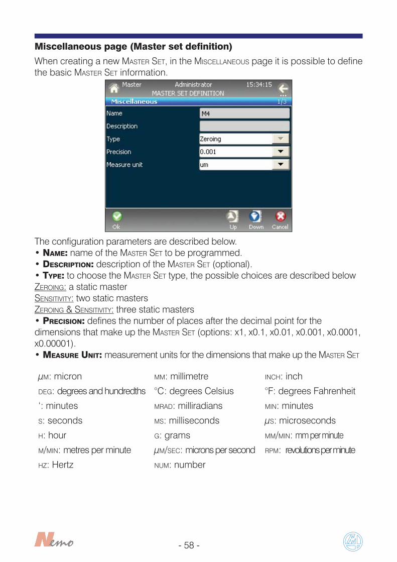
Miscellaneous page (Master set definition)
When creating a new MASTER SET, in the MISCELLANEOUS page it is possible to define the basic MASTER SET information.
The configuration parameters are described below.• NAME: name of the MASTER SET to be programmed.• DESCRIPTION: description of the MASTER SET (optional).• TYPE: to choose the MASTER SET type, the possible choices are described belowZEROING: a static masterSENSITIVITY: two static mastersZEROING & SENSITIVITY: three static masters• PRECISION: defines the number of places after the decimal point for the dimensions that make up the MASTER SET (options: x1, x0.1, x0.01, x0.001, x0.0001, x0.00001).• MEASURE UNIT: measurement units for the dimensions that make up the MASTER SET
μM: micron MM: millimetre INCH: inch
DEG: degrees and hundredths °C: degrees Celsius °F: degrees Fahrenheit
‘: minutes MRAD: milliradians MIN: minutes
S: seconds MS: milliseconds μS: microseconds
H: hour G: grams MM/MIN: mm per minute
M/MIN: metres per minute μM/SEC: microns per second RPM: revolutions per minute
HZ: Hertz NUM: number
- 59 -
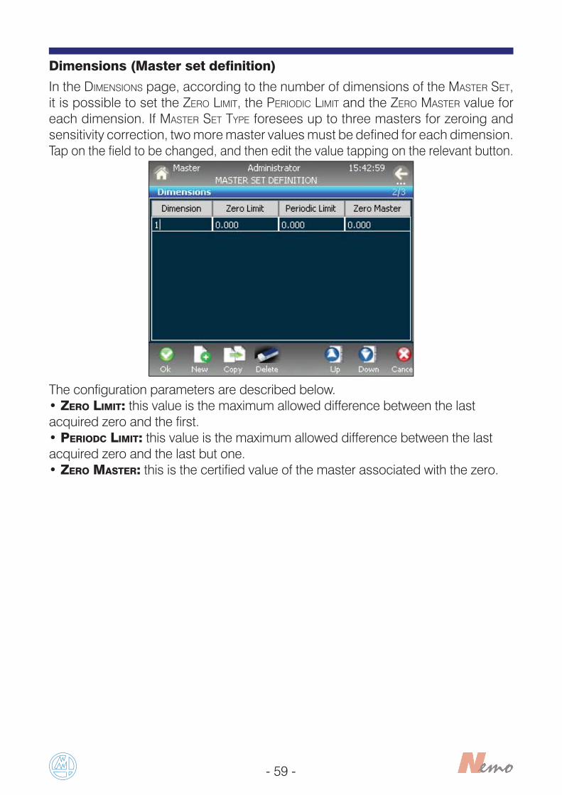
Dimensions (Master set definition)
In the DIMENSIONS page, according to the number of dimensions of the MASTER SET, it is possible to set the ZERO LIMIT, the PERIODIC LIMIT and the ZERO MASTER value for each dimension. If MASTER SET TYPE foresees up to three masters for zeroing and sensitivity correction, two more master values must be defined for each dimension.Tap on the field to be changed, and then edit the value tapping on the relevant button.
The configuration parameters are described below.• ZERO LIMIT: this value is the maximum allowed difference between the lastacquired zero and the first.• PERIODC LIMIT: this value is the maximum allowed difference between the last acquired zero and the last but one.• ZERO MASTER: this is the certified value of the master associated with the zero.
- 60 -
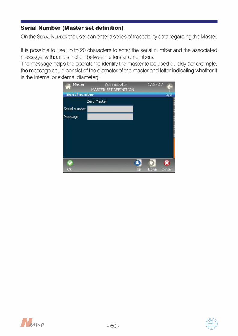
Serial Number (Master set definition)
On the SERIAL NUMBER the user can enter a series of traceability data regarding the Master.
It is possible to use up to 20 characters to enter the serial number and the associated message, without distinction between letters and numbers.The message helps the operator to identify the master to be used quickly (for example, the message could consist of the diameter of the master and letter indicating whether it is the internal or external diameter).

- 61 -
7 MEASURE
To enter in MEASURE page
To enter in BATCHES menu
Tap this button in HOME PAGE to enter in MEASURE menu.

- 62 -
7.1 MEASURE
Tap this button in MEASURE menu to enter in MEASURE page.
This page allows the user to view the measurements acquired by the devices connected to the Nemo in real time. Up to 8 measurements (4 OK/NG+4 auxiliary)may be displayed simultaneously; if there are more than 4 measurements it is necessary to scroll the page in order to view all of them. If there is more than one step, the steps that correspond to the current measurement are highlighted in yellow.
The functions of this page are described below:
• START: to start the measurement sequence or the measure step acquisition. • STOP: to stop the measuring step acquisition or if it is the last step, to stop the measurement sequence.• UP: to see the upper lines of measure (if the measurements are more than four).• DOWN: to see the lower lines of measure (if the measurements are more than four).• DELETE: the DELETE function enables the user to delete the last acquisition.If this button is tapped during a step acquisition, the operator can decide whetherto delete the last step only or all the previous ones, (limited to the steps associated with the last part).
The ZEROING functions allow to set/reset a zero value on the transducer. This value is for set-up purpose only, and does not affect the measurement value.Tap on ZEROING to carry out the device electrical zeroing procedure.This button will be displayed only if a Master Set is associated to the characteristic in use.

- 63 -
Tap on CHART button to display the page containing the controlchart for the batch in use. After that, the following page will be displayed.
Tap on OFFSET button to display the zero adjustment page. After that, the below page will be displayed.
Selecting the option REAL VALUE you can carry out the zero adjustment sampling the value, instead selecting the option OFFSET you can carry out manually the zero adjustment.This page was specifically designed to help the user on programming of OBD (Over Ball Dimension) issues.

- 64 -
1 2 3
4 5 6 7
Bar
1) Name of the active BATCH
2) PART PROGRAM name3) STEP name4) Number of GOOD parts (percentage of OK parts)5) Number of SCRAP parts (percentage of NG parts)6) Number of TREND parts (percentage of TREND parts)7) Total number of measured parts8)
Good parts
Trend parts
Reject parts
8

- 65 -
7.2 BATCHES
Tap this button in MEASURE menu to enter in BATCHES pages.
This menu contains the commands that are used to manage the BATCHES, i.e. the data structures used for collecting the measurements. The BATCHES are used prima-rily to store the data, but also to arrange the measurements in layers according tothe time they were collected in order to prepare the data for further statistical analysis (in a separate off line device) and to correlate the data collection with theproduction BATCHES.
In this page, you can find an Open Batches list, where you can use the followingfunctions:
• MEASURE: to enter in measure page of the selected Batch.• ALL: to view all the Batches (both opened and closed).

- 66 -
The ALL function can be used to view all active and closed batches and generate an alternative command list that enables the operator to work on closed BATCHES, exporting and deleting them.
In addition to the usual options, you can perform the following operations:
• EXPORT: to export the selected BATCH to a file. The user may decide to export only the measurements, other correlated data, or the measurements and the other correlated data. • TRANSFER: to export all the batches on an USB key.• OPEN: to open a closed batch.• CLOSE: to close an opened batch.• OPENED: to view only the opened batches.
Note: The EXPORT and TRANSFER functions are available only for the closed batches.

- 67 -
Batch editingCreating a new BATCH, runs the following window, where you can select the PART PROGRAM associated with the new BATCH.
Once the PART PROGRAM has been associated, the following set-up pages are available.Note: The following pages are the same both for the creation of a new batch and for the update of an existing batch.
The configuration parameters are described below.• NAME: name of the BATCH to be programmed.• I/O INDEX: the I/O index function allows to automatically switch BATCH, and relevant part program associated, through a digital input sent by an external logic (PLC) or manually by a push button/rotary switch.• SELECTION CHANNEL: to select the TRANSDUCER that triggers the change. Each transducer may only be used to select a single batch.
Miscellaneous page (Batch definition)

- 68 -
In CLOSE BATCH page, you can change the following parameters about the action on batch closing:
• AUTOMATIC DATA EXPORT: NO, MEASURE.
Close batch (Batch definition)
In BATCH DURATION page, you can set the maximum number of the batch parts.The default value and the upper limit is 20000 parts. It is possible to manage the lenght of a batch through the hours and the minutes programmable.
Batch duration (Batch definition)
Note: If you select the automatic closure when a new batch is created, it will not be possible to modify the main parameters (e.g. tolerance, etc.). The minimum time between a stop cycle and the next start cycle is 1 second.

- 69 -
8 SERVICE
To enter in TRANSDUCERS VIEW page
To enter in I/O LINES MAP page
To enter in LIVE MEASURE page
Tap this button in HOME PAGE to enter in SERVICE menu.
- 70 -
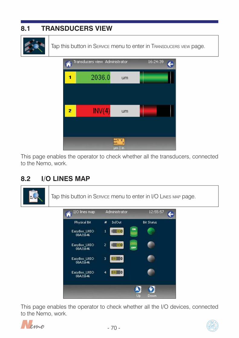
8.1 TRANSDUCERS VIEW
Tap this button in SERVICE menu to enter in TRANSDUCERS VIEW page.
This page enables the operator to check whether all the transducers, connected to the Nemo, work.
8.2 I/O LINES MAP
Tap this button in SERVICE menu to enter in I/O LINES MAP page.
This page enables the operator to check whether all the I/O devices, connected to the Nemo, work.

- 71 -
8.3 LIVE MEASURE
This page displays the measurements in real time, even if they are not associated with a batch and without START and STOP.
Tap this button in SERVICE menu to enter in LIVE MEASURE page.
Tap PARTS, to select from the list the desired PART PROGRAM then tap on OK.
Note: At least one part must have been set-up to enable this function.

- 72 -

- 73 -
________________________________________________________________________
________________________________________________________________________
________________________________________________________________________
________________________________________________________________________
________________________________________________________________________
________________________________________________________________________
________________________________________________________________________
________________________________________________________________________
________________________________________________________________________
________________________________________________________________________
________________________________________________________________________
________________________________________________________________________
________________________________________________________________________
________________________________________________________________________
________________________________________________________________________
________________________________________________________________________
________________________________________________________________________
________________________________________________________________________
________________________________________________________________________
________________________________________________________________________
NOTES:

- 74 -
________________________________________________________________________
________________________________________________________________________
________________________________________________________________________
________________________________________________________________________
________________________________________________________________________
________________________________________________________________________
________________________________________________________________________
________________________________________________________________________
________________________________________________________________________
________________________________________________________________________
________________________________________________________________________
________________________________________________________________________
________________________________________________________________________
________________________________________________________________________
________________________________________________________________________
________________________________________________________________________
________________________________________________________________________
________________________________________________________________________
________________________________________________________________________
________________________________________________________________________
NOTES:

- 75 -
________________________________________________________________________
________________________________________________________________________
________________________________________________________________________
________________________________________________________________________
________________________________________________________________________
________________________________________________________________________
________________________________________________________________________
________________________________________________________________________
________________________________________________________________________
________________________________________________________________________
________________________________________________________________________
________________________________________________________________________
________________________________________________________________________
________________________________________________________________________
________________________________________________________________________
________________________________________________________________________
________________________________________________________________________
________________________________________________________________________
________________________________________________________________________
________________________________________________________________________
NOTES:

2002/95/CE2002/96/CE
INFORMATION FOR USERSconcerning the terms of the National Legislation enforcing the Directives 2002/95/EC, 2002/96/EC and 2003/108/EN on the restriction of the use of certain hazardous substances in electrical
and electronic equipment, and the disposal of waste materialsThe wheelie bin symbol with a cross through it on the equipment or its packaging indicates that the product must be disposed of separately from other waste materials at the end of its working life.If the user wishes to dispose of this equipment, he/she must do so in accordance with the applicable National regulations governing the separation of the unit into its waste materials at the end of its working life. Separating waste materials correctly before submitting the equipment for recycling, treatment and environmentally compatible disposal can help to prevent potentially negative effects on health and the environment, as well as making it easier to reuse and/or recycle its constituent materials. Failure to dispose of this product in accordance with these indications is punishable in accordance with the applicable laws.
A full, up-to-date list of addresses is available at the offi cial Marposs web site: www.marposs.comD2NE1300SG – Edition 10/2013 – Details may change without prior notice.© Copyright 2013 MARPOSS S.p.A. (Italy) – All rights reserved.MARPOSS, and other names/signs relative to Marposs products, referred to or shown in this document are registered trade marks or trade marks of Marposs in the United States and in other countries. Any third party rights relating to trade marks or registered trade marks referred to in this document are recognised for the respective holders.Marposs has an integrated Company Management system for quality, the environment and safety, with the following certifi cation: ISO 9001, ISO 14001, OHSAS 18001 and QS9000 T&E. Marposs has also been awarded EAQF 94 and the Q1-Award.