d4.4 optical layer supervision tools and processes for ...€¦ · optical layer supervision tools...
TRANSCRIPT

D4.4
Optical layer supervision tools and
processes for long reach optical access
Dissemination Level: PU
• Dissemination level:
PU = Public,
RE = Restricted to a group specified by the consortium (including the Commission Services),
PP = Restricted to other programme participants (including the Commission Services),
CO = Confidential, only for members of the consortium (including the Commission Services)
Ref. Ares(2014)2247513 - 07/07/2014

Abstract:
This document includes an analysis of advanced technologies for optical supervision and fiber management in Long Reach Passive Optical Networks (LR-PONs).
A generic model for estimating the operational savings of optical supervision in PONs is reported in Section 3.
Based on the primary reference architectures of the access network considered in DISCUS, various approaches for integrating advanced technologies for optical supervision in LR-PONs are reported in Section 4. Optical Time Domain Reflectometry (OTDR) is studied both using external devices and including OTDR embedded inside the PON transceivers. A feasible framework for PON diagnostic using alarms of active elements in DISCUS LR-PONs is also described.
In Section 5, an analysis of ultra-fast link restoration approaches in PONs considering 1+1 and N:1 dual homing protection for application in DISCUS access architecture is reported.
Finally, section 6 describes systems for fiber management based on Radio-Frequency Identification technology and remotely powered (using light) intelligent devices in the PON infrastructure, with the potential to provide relevant operational advantages to DISCUS fiber access network.

COPYRIGHT
© Copyright by the DISCUS Consortium. The DISCUS Consortium consists of: Participant
Number
Participant organization name Participant org.
short name
Country
Coordinator
1 Trinity College Dublin TCD Ireland
Other Beneficiaries
2 Alcatel-Lucent Deutschland AG ALUD Germany
3 Nokia Siemens Networks GMBH & CO. KG NSN Germany
4 Telefonica Investigacion Y Desarrollo SA TID Spain
5 Telecom Italia S.p.A TI Italy
6 Aston Universtity ASTON United
Kingdom
7 Interuniversitair Micro-Electronica Centrum
VZW
IMEC Belgium
8 III V Lab GIE III-V France
9 University College Cork, National University of
Ireland, Cork
Tyndall & UCC Ireland
10 Polatis Ltd POLATIS United
Kingdom
11 atesio GMBH ATESIO Germany
12 Kungliga Tekniska Hoegskolan KTH Sweden
This document may not be copied, reproduced, or modified in whole or in part for any purpose without written permission from the DISCUS Consortium. In addition to such written permission to copy, reproduce, or modify this document in whole or part, an acknowledgement of the authors of the document and all applicable portions of the copyright notice must be clearly referenced.
All rights reserved.

Authors:
Name Affiliation
Julio Montalvo TID
Joerg Hehmann ALUD
Jiajia Chen KTH
Marco Ruffini TCD
Alan Hill TCD
Internal reviewers:
Name Affiliation
Nick Parsons Polatis
Rich Jensen Polatis
Marco Schiano TI
Andrea Di Giglio TI
Due date: (M18) 30 April 2014

TABLE OF CONTENTS
1 INTRODUCTION ....................................................................................................................... 6
2 REFERENCE SCENARIOS ........................................................................................................ 7
3 OPERATIONAL EXPENDITURE MODEL FOR OPTICAL SUPERVISION IN PONS .. 9
3.1 OPEX SAVING BY USING AUTOMATIC FAULT MONITORING ....................................................................... 9
3.2 OPEX ANALYSIS FOR THE SUPERVISION SCHEMES COMPATIBLE TO THE RESILIENT PON
ARCHITECTURE .............................................................................................................................................................. 10
4 ADVANCED TECHNOLOGIES, MECHANISMS AND STANDARDS FOR PHYSICAL LAYER
SUPERVISION IN PONS .................................................................................................................. 12
4.1 OPTICAL TIME DOMAIN REFLECTOMETRY (OTDR) .............................................................................. 12
4.1.1 External OTDR approach .................................................................................................................... 14
4.1.2 Transceiver-embedded OTDR approach ...................................................................................... 19
4.2 OPTICAL LINE SUPERVISION AND DIAGNOSTIC IN PONS ....................................................................... 24
4.3 BIDIRECTIONAL PERMANENT FIBRE MONITORING SYSTEM PROPOSAL ............................................. 26
4.4 ACTIVE DEMARCATION POINTS .................................................................................................................. 29
5 CONTROL PLANE-BASED LINK RESTORATION IN PONS ......................................... 32
5.1 1+1 DUAL-HOMING PROTECTION ............................................................................................................. 32
5.1.1 Failure Detection .................................................................................................................................... 33
5.1.2 Reactivation Methods ........................................................................................................................... 33
5.2 POSSIBILITIES FOR DUAL-HOMED N:1 PROTECTION ............................................................................. 34
5.2.1 Failure Detection .................................................................................................................................... 34
5.2.2 Reactivation Methods ........................................................................................................................... 35
5.2.3 Summary of Reactivation Requirements for Feeder Fibre Failure ................................. 38
5.3 ADDITIONAL DRIFT DUE TO WAVELENGTH CHANGES AFTER FAILURE ............................................. 39
6 SYSTEMS FOR FIBRE MANAGEMENT IN OPTICAL NETWORKS ............................. 40
7 SUMMARY AND CONCLUSIONS ......................................................................................... 43
8 REFERENCES ........................................................................................................................... 44
ABBREVIATIONS ........................................................................................................................... 46

1 Introduction
A simple schematic of the DISCUS architecture [1] is shown in Figure 1. It shows a dual homed Long Reach Passive Optical Network (LR-PON) bypassing existing local exchanges and terminating on the metro-core nodes. The metro-core (MC) nodes are interconnected with an optical circuit switched wavelength layer.
The overall architecture consists of three major parts; the LR-PON Access network, the metro-core node and the flat optical core-network.
Fig. 1. Schematic of the DISCUS architecture. DP: Distribution Point.
In the DISCUS architecture, the traditional metro network is shifted to and merged with the flat optical network. The DISCUS access segment consists of a Long-Reach PON with up to 100 km reach and large split ratio up to 1:512, consisting of a Wavelength Division Multiplexing (WDM) backhaul fibre and cascaded amplified optical power splitters in the outside plant.
In this Deliverable, we analyse the main monitoring challenges for the LR-PON fibre infrastructure and study advanced optical supervision tools and processes suitable for monitoring and managing the LR-PON fibre network.

2 Reference scenarios
In the following figures, we show the basic DISCUS LR-PON topologies. Fibres between MC nodes and Local Exchanges/Central Offices (LE/CO) are named backhaul fibres; fibres between the LE/CO and the 1st splitting stage are named feeder fibres; fibres between the 1st and 2nd power splitting stages are named distribution fibres; and finally, fibres connecting the 2nd splitting remote node (RN) and users are named drop fibres.
Fig. 2 shows the standard architecture with basic dual parenting and protection in dense urban scenarios, and Fig. 3 shows a more cost-effective scenario for rural areas with an increased length of the Optical Distribution Network (ODN) and a shrunken backhaul.
Fig. 2. DISCUS LR-PON standard architecture with basic dual parenting and protection in dense urban
scenarios

Fig. 3. DISCUS LR-PON design option with increased ODN length for rural areas
Fig. 4 shows an additional scenario where connected customers demand special security requirements and thus they prefer a point to point physical communication. Using wavelength filtering elements in the remote node, such as an Arrayed Waveguide Grating (AWG), each customer only receives a dedicated optical channel, and the channels corresponding to other customers are blocked in this port at the remote node.
Fig. 4. Filtered WDM-PON architecture for users requiring dedicated optical channel.
Both scenarios in Fig. 2 and Fig. 3 consider bi-directional amplification at least in the first LE connected to the Metro-Core node, as well as 1+1 protection of backhaul fibre and OLT, so that if a fault occurs either at the working OLT or backhaul fibre, the service

provided to ONT/ONUs can be restored using the protection backhaul fibre and a backup OLT in a stand-by Metro-Core Node.
By including optical supervision tools and processes to manage the optical layer of the fibre infrastructure, relevant operational savings can be achieved by the fibre network operator.
In the following sections, we provide the analysis of advanced approaches for physical layer supervision and management in PONs, specifically focusing on the main DISCUS LR-PON reference scenarios shown in the former figures.
3 Operational Expenditure model for optical supervision in
PONs
The operational expenditures (OPEX) model for monitoring schemes here covered two cases: 1) analysis of OPEX saving by using remote and automatic fault monitoring; and 2) analysis of OPEX saving by employing specific supervision schemes in different deployment scenarios, e.g. urban and rural service areas, schemes with and without protection, etc.
3.1 OPEX saving by using automatic fault monitoring
In this section, we calculate OPEX reductions achieved through remote fault localization [2] with regards to an in-field approach requiring technician dispatches and hand-held terminals.
Let one assume man-hour cost, mC , to be 4 times higher in well-developed countries with respect to developing countries (high versus low man hour cost, see Fig. 5), and K to be the probability that drop-line fault occurred per year per Optical Line Terminal (OLT) chassis supporting a total number of Optical Network Terminals (ONTs) Q=3072, i.e. 12 line-cards with 8 PON ports each having a 1:32 split-ratio. The potential savings, depicted in Fig. 5, start already at 0.065% and 0.25% of drop lines faults per OLT per year, which correspond to less than 2 and less than 8 faulty lines in well-developed and
developing countries, respectively. The cost-savings per year, SC , are calculated according to the formula:
%1001 ⋅
−=
− fieldin
remoteS
C
CC
(1)
where
d
hhandheldfieldinmfieldin
T
CQTCKC −
−−+⋅⋅⋅=
(2)

d
hremoteremote
T
CC −
=
(3)
are the costs resulting from in-field and remote fibre-fault localization per year,
respectively. The time needed for the in-field test, fieldinT− is estimated as 3 hours which
includes transportation to and from the field, arrangements and tests, while remote test does not need any labour costs. Besides, the above expressions embrace also the costs
of the necessary hardware for monitoring on a per-OLT-chassis basis. hhandheldC− is the
cost of handheld portable equipment and hremoteC− is the cost of hardware enabling
remote operation, both distributed over the depreciation time, dT , of five years. We
assume hremoteC− to be 30% more expensive than hhandheldC
− due to extensive capabilities and higher performance requirements.
Taking an example of German network where the average drop fibre length is 1.5km for dense urban and 3.5 km for rural scenario, the percentage of drop line faults per OLT per year could reach up to 0.876% and 2.044% considering a typical mean time between failures of 1500000 hours for distribution cables. In Fig. 5, it can be seen around 74% (in dense urban) and 87% (in rural) savings could be obtained for German network by remote fault localization compared to in-field solution.
Figure 5: Potential cost savings achieved by in-field and remote fibre testing solutions
3.2 OPEX analysis for the supervision schemes compatible to the resilient
PON architecture
In this case, we analyze the failure related OPEX for fault supervision approaches and take the supervision schemes presented in [2] using OTDR (optical time domain

reflectometry) as example to show the cost results. The optical supervision technology is described later in more detail in section 4.1.1.
Our considered failure related OPEX consist of both the failure reparation and penalty introduced by the service disruption. Penalty cost typically can be expressed as the product of the penalty rate and the connection interruption time. In this study, the operational time of an access network is assumed to be 20 years. We consider two deployment scenarios, namely urban (collective) and rural (dispersive), which correspond to dense and sparse populated areas, respectively.
In our proposed scheme [2] , if time T are needed to get one stable OTDR trace, for a certain drop line the average time to automatically detect and localize its fault is T*N*L/K/2. Therefore, compared to the single-thread case (i.e. K=1), the multi-thread approach (i.e. K>1) can save T*N*L*(1-1/K)/2 in average for fault monitoring, which indicates the mean time to repair (MTTR) for the distribution fibres (DFs) and optical network terminal (ONTs) can be reduced correspondingly. According to the commercial fibre plant manager product, typically 3 minutes are required in order to have an acceptable signal-noise-ratio on the OTDR trace. The achieved operational saving by using our scheme due to the reduction of the MTTR for the DFs and ONTs is presented in Fig. 6, where the penalty and reparation costs of different considered scenarios are normalized to the total OPEX of the unprotected PON with single-thread fault monitoring in dense populated area (i.e. K=1 in collective case). The normalized added capital expenditures (CAPEX) by employing the proposed supervision scheme (i.e. the introduction of OTDR based system at central office, and the additional components at remote node) is approximately 0.08%. Here, only trivial difference on the additional CAPEX is caused between the various considered scenarios, because the OTDR module is the main factor for the increase of deployment cost. It can be seen with a minor CAPEX increase the proposed multi-thread based monitoring scheme can significantly decrease the service interruption penalty, which is in particular important for business access and mobile backhauling. The larger the number of monitoring threads (i.e., K) is, the higher the OPEX saving obtains. Compared to the unprotected PON, the OPEX deduction is more obvious in the DISCUS cases - (where dual-parental protection is considered), as unprotected distribution part (including DFs and ONTs) becomes dominating to trigger service disruption. Since the amount of DFs in dispersive case is much larger than in collective area, the OPEX saving for the sparse populated area is apparently higher than for the dense scenario.

Figure 6: Failure related OPEX saving for considered scenarios normalized by the total OPEX related
to fault management of the unprotected PON in urban area with K=1.
4 Advanced technologies, mechanisms and standards for
physical layer supervision in PONs
4.1 Optical Time Domain Reflectometry (OTDR)
For troubleshooting the physical layer, Optical Time Domain Reflectometers (OTDRs) are typically used. These devices periodically transmit optical signals modulated with electrical pulses into the fibres to test, and receive the backscattered signal from the fibre, thus characterizing the fibre through distance. There is a tradeoff between the time width of the OTDR pulses (ns to us) and the measurement performance in terms of maximum distance (dynamic range1) and two-point resolution (event dead zone2, attenuation dead zones3). The shorter the pulses, the shorter the maximum distance value, but the better then two-point resolution.
OTDRs can be used for Operation and Maintenance (O+M) of fibre networks in two ways:
- De-centralized approach, which involves a technician dispatched to Outside Plant (OSP) with portable OTDR when the network operation centre (NOC) detects an alarm which may be caused by a fibre fault.
1 Dynamic range (dB): Ratio between the extrapolated point of the backscatter trace at the near end of
the fibre under test and the noise level reference at the fibre end.
2 Event dead zone: Distance between two opposite points (1.5 or 3 dB) down from the unsaturated peak of a single reflective event.
3 Region after an event where the displayed trace deviates from the undisturbed backscatter trace more than a given vertical value (0.1 or 0.5 dB).

- Centralized approach, which involves using OTDR functions and remote active supervision elements for diagnosing Optical Distribution Networks (ODN) from the Central Office in case of active alarms. A variation of this approach is using an OTDR in the Central Office where Optical Line Terminals (OLTs) of a PON are located, and Fibre Bragg Grating (FBG) or Thin Film Filter (TFF) based optical reflectors in the Optical Network Unit (ONU) side [3] . This allows discriminating between a communication problem due to ONU failure and a physical layer failure.
For the centralized approach, novel alternatives have also been proposed for increasing system performance by partially avoiding traces overlapping behind power splitters. These approaches are based on the use of Multi-wavelength OTDRs with selectable wavelength of the test signal, in combination with special splitters [4] in the outside plant.
Nevertheless, the backscattering coefficient in optical fibres is very low (around -80dB in single-mode fibre for 1ns pulses) and in case of remote measurements, the measured signal suffers a two way attenuation, thus OTDR receivers require a very high performance with very low Noise Equivalent Power (NEP). Using analog detection, OTDR receivers can typically achieve a maximum dynamic range value around 47 dB, while 55 dB can be achieved using photon-counting OTDRs (10 us pulses) [7] .
A more challenging situation appears when a point to multipoint topology is under test, such as the case of PONs, because the OTDR signal is highly attenuated by optical power splitters and the reflections from different remote fibre branches are overlapped in time at the OTDR receiver.
Both in-line and dark fibre supervision approaches can be used for OTDR supervision. In-line supervision employs an optical signal within each PON for monitoring purposes. On the other hand, dark fibre supervision uses fibres, unused for data transmission, which are reserved for monitoring purposes, this dark fibres sharing as much as possible the same fibre cables and ducts as the PON fibres.
In the case of in-line OTDR PON supervision, the standard waveband recommended by ITU-T [3] is the U-band, which covers the 1625nm-1675nm range. The U-band is specified for monitoring purposes when communication wavelength band extends up to the L-band, thus this band is suitable not only with GPON and EPON, but even with emerging XG-PON deployments and, in the future, with NGPON2 systems and beyond. The hybrid Time Division Multiplexing/Wavelength Division Multiplexing (TDM/WDM) LR-PON in DISCUS is looking beyond NG-PON2 to provide even higher capacities by increasing the wavelength domain utilisation with a Dense WDM channel plan of up to 40 wavelengths each for up- and down-stream within C-band (1530nm-1565nm). Standard U-band can then be used for fibre supervision in DISCUS LR-PONs.
In the case of using reserved dark fibres attached to PON fibre infrastructure for supervision, there is no restriction in the waveband of the OTDR monitoring signal.
The following subsections examine in detail the external OTDR and transceiver-embedded OTDR approaches and show how then can be used in the DISCUS reference architectures.

4.1.1 External OTDR approach
The external OTDR approach consists of employing an OTDR device separated from the PON transceiver.
When in-line supervision is chosen, this approach is typically done in a centralized way by co-locating an OTDR, optical switches and wavelength multiplexers in the network operator premises so that an OTDR device or card can be shared by several OLTs and their respective ODNs.
Previous to DISCUS technologies, these implementation would be located in the old LE/CO locations, thus the OTDRs and optical switches and multiplexers can be re-utilized and shared for all ODNs supervision at the LE/CO, as shown in Figure 7.
Fig. 7. External OTDR located in old LE/CO for in-line ODN supervision.
With this approach, feeder fibres can be monitored as point to point fibres with the OTDR, and distribution fibres can also be monitored, but overlapping between traces in the OTDR receiver will take place.
For increased sharing of the OTDR between ODNs (thus reducing the number of multiplexers and the size of the optical switch), multiplexers can be used before the DISCUS 4x4 splitter; in this case, however, overlapping between feeder fibre traces will take place in the OTDR receiver. Multiplexers can be avoided if 5x4 power splitters are used instead of 4x4, thus reducing the number of elements and insertion loss, see Fig. 8 (b), where the additional input ports in the power splitters are marked in dashed lines.
(a) (b)
Fig. 8. External OTDR located in old LE/CO for in-line ODN supervision, using 4x4 (a) and 5x4 (b)
power splitters in the LE/CO.
For all the former cases, it is assumed that the LE/CO keeps a management channel with the Operations and Support Systems (OSS) of the network operator by other means than the PON, so that the OTDR measurements can be reported and analysed by the Operations and Maintenance (O+M) systems.
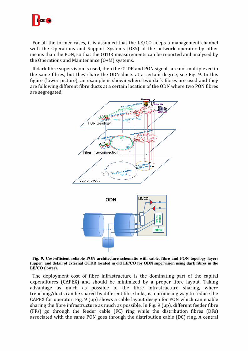
If dark fibre supervision is used, then the OTDR and PON signals are not multiplexed in the same fibres, but they share the ODN ducts at a certain degree, see Fig. 9. In this figure (lower picture), an example is shown where two dark fibres are used and they are following different fibre ducts at a certain location of the ODN where two PON fibres are segregated.
Fig. 9. Cost-efficient reliable PON architecture schematic with cable, fibre and PON topology layers
(upper) and detail of external OTDR located in old LE/CO for ODN supervision using dark fibres in the
LE/CO (lower).
The deployment cost of fibre infrastructure is the dominating part of the capital expenditures (CAPEX) and should be minimized by a proper fibre layout. Taking advantage as much as possible of the fibre infrastructure sharing, where trenching/ducts can be shared by different fibre links, is a promising way to reduce the CAPEX for operator. Fig. 9 (up) shows a cable layout design for PON which can enable sharing the fibre infrastructure as much as possible. In Fig. 9 (up), different feeder fibre (FFs) go through the feeder cable (FC) ring while the distribution fibres (DFs) associated with the same PON goes through the distribution cable (DC) ring. A central

office (CO) typically supports more than one single PON. Hence, it accommodates more than one OLT and connects to more than one Remote Node.
For the converged fixed and mobile network shown in Fig. 9, tree based logical topology (i.e. point-to-multipoint PtMP) for passive optical network (PON) can be mapped to ring based cable layout to enhance resiliency. This cable layout also opens the possibility to have dark fibre monitoring scheme, where a fibre deployed in the same cable but not used for any working PONs yet can carry out the supervision signals for fault monitoring. In this way, the major cable fault (e.g. cut, bending, etc.) can be easily detected. As the supervision signal goes through the dark fibre, it can be shared by all the other fibres in the same cable and does not affect any working signals (in either the spectral domain or time domain). On the other hand, to cover both feeder and distribution sections we may need a lot of dark fibres. Then important future work will be on how to minimize the amount of dark fibres to cover all the service areas to be monitored.
External OTDRs can also be located in DISCUS M/C nodes for backhaul fibres and inter-MC node fibres supervision, see Fig. 10. In the case of PON backhaul fibre supervision, it is required to add the OTDR signal after the first amplifier, as the operation waveband of amplifiers does not include the band reserved for OTDR.
(a) (b)
Fig. 10. External OTDR located in M/C Nodes for PON backhaul fibres and inter-MC node fibres
supervision using in-line (a) and dark fibres (b).
4.1.1.1 External OTDR case for Point-to-Point services using PON
In this section, we investigate a supervision scheme with external OTDR with selectable operation wavelength, which could be compatible with the cost-efficient and reliable fibre layout architecture for wavelength division multiplexing (WDM) based passive optical networks (PONs) [8] . WDM based PON is widely considered for business users and mobile backhauling, where high bandwidth and high security are required.
Our scheme concerns measurement of optical time domain reflectometry (OTDR) groups in several Distribution Fibres (DFs) at a time via embedded monitor ports in the remote node. Compared with the conventional scheme where DF is monitored one by one (i.e., single thread), our scheme can be referred to multi-thread case, which reduces the total time to monitor the whole PON. Fig. 11 shows a DISCUS LE/CO and M/C node with our supervision approach. A commercial OTDR device with external wavelength
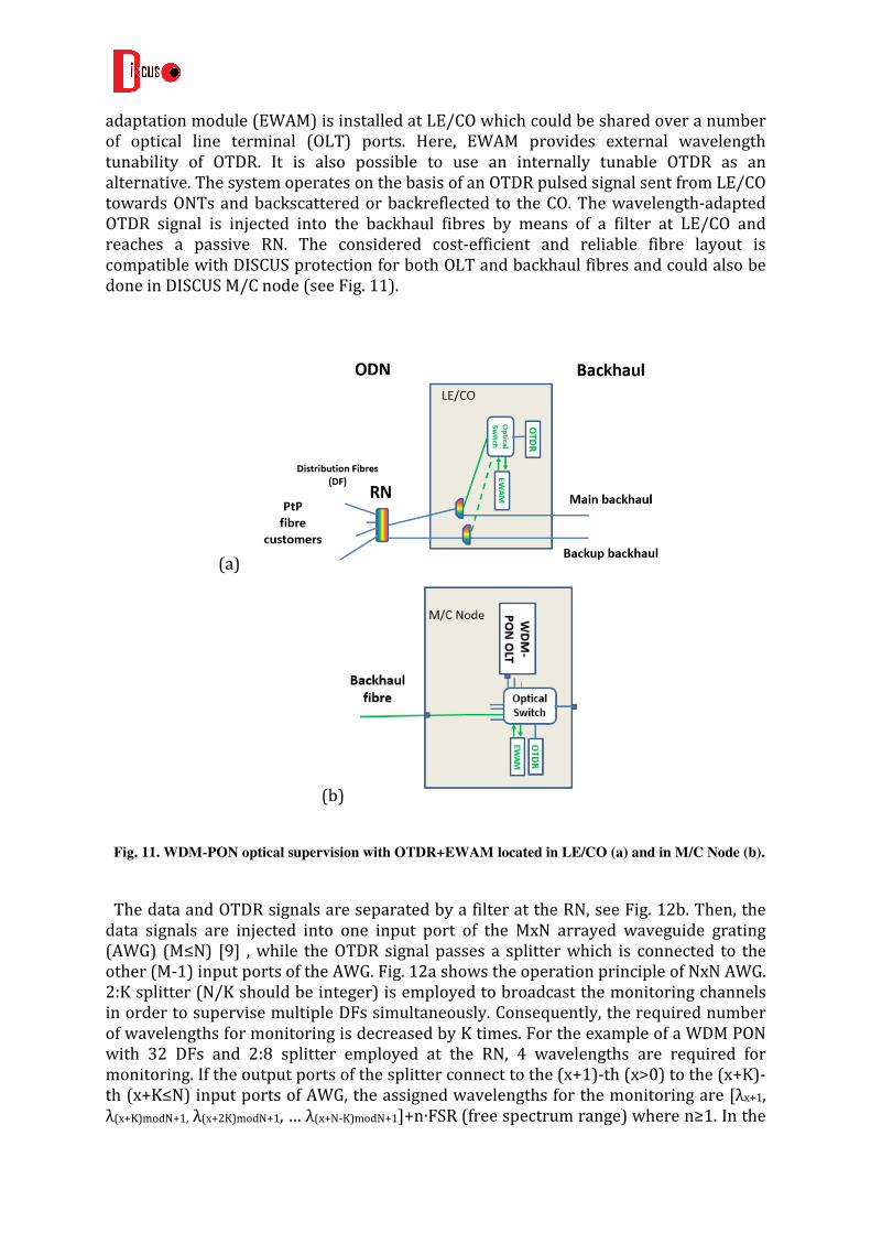
adaptation module (EWAM) is installed at LE/CO which could be shared over a number of optical line terminal (OLT) ports. Here, EWAM provides external wavelength tunability of OTDR. It is also possible to use an internally tunable OTDR as an alternative. The system operates on the basis of an OTDR pulsed signal sent from LE/CO towards ONTs and backscattered or backreflected to the CO. The wavelength-adapted OTDR signal is injected into the backhaul fibres by means of a filter at LE/CO and reaches a passive RN. The considered cost-efficient and reliable fibre layout is compatible with DISCUS protection for both OLT and backhaul fibres and could also be done in DISCUS M/C node (see Fig. 11).
(a)
(b)
Fig. 11. WDM-PON optical supervision with OTDR+EWAM located in LE/CO (a) and in M/C Node (b).
The data and OTDR signals are separated by a filter at the RN, see Fig. 12b. Then, the data signals are injected into one input port of the MxN arrayed waveguide grating (AWG) (M≤N) [9] , while the OTDR signal passes a splitter which is connected to the other (M-1) input ports of the AWG. Fig. 12a shows the operation principle of NxN AWG. 2:K splitter (N/K should be integer) is employed to broadcast the monitoring channels in order to supervise multiple DFs simultaneously. Consequently, the required number of wavelengths for monitoring is decreased by K times. For the example of a WDM PON with 32 DFs and 2:8 splitter employed at the RN, 4 wavelengths are required for monitoring. If the output ports of the splitter connect to the (x+1)-th (x>0) to the (x+K)-th (x+K≤N) input ports of AWG, the assigned wavelengths for the monitoring are [λx+1, λ(x+K)modN+1, λ(x+2K)modN+1, … λ(x+N-K)modN+1]+n∙FSR (free spectrum range) where n≥1. In the

example shown in Fig.10, x=1, N=32, K=8, and M=9. It should be noted if adapting this scheme in single-thread case (i.e. K=1), the splitter is not needed. This system imposes only minor power budget degradation for data channels caused by the insertion loss of the filter at RN.
The backup feeder can be connected to any free input port of NxN AWG. Although the assigned wavelength for a certain ONT in protection mode is changed, it will not introduce extra expense since a colorless-ONT should support any wavelength used in the same WDM PON. The example shown in Fig. 10 is with x=1, N=32, K=8, and M=10. Furthermore, we should keep K≤8 to guarantee 1dB event sensitivity. It is because higher splitting ratio decrease sensitivity due to the overlapping light backscattered from all drop ports masking the events, e.g. 1 dB fault is detected in a fully-fiberized 1:8 splitter as 0.1 dB step on the reflectogram which is the event detection threshold of a regular OTDR. As up to 8 drop lines are able to be measured simultaneously, the monitoring time used for fault detection and localization of one PON could decrease to 12.5%.
(a)
(b)
Fig. 12. Principle of operation of NxN AWG (a) and Remote Node with wavelength plan schematic.
FSR: Free Spectral Range.

4.1.2 Transceiver-embedded OTDR approach
The basic idea of the embedded OTDR approach is to integrate the OTDR measurement function into the data transmission system. The main advantage of this approach is to link the measurement function with the data transmission. This is realized by using the same wavelength by an on top modulation of the OTDR signal to the data stream. The solution also fits very well if WDM PON architectures are used. The OTDR signal follows the data stream through the network so that the OTDR result is linked directly to the data path. The capability of the eOTDR solution in DISCUS LR-PON architectures will be analysed in the following sections.
3.1.2.1 Embedded OTDR architecture
The main challenge for the embedded OTDR approach was to integrate its distributed sub functions into the PON transmission system [9] . All configuration and analysis tasks should be done in a centralised OTDR diagnosis and test centre. A standard management protocol can be used to transfer the OTDR parameter to the central offices and their OLTs. The OTDR results will be transferred via a standard file transfer from the central offices to the OTDR diagnosis and test centre. The management information base (MIB) of the transmission system was extended to provide the OTDR parameter for the OTDR controller function at the OLT. The OTDR controller itself manages the OTDR measurements from the data transceiver. The configuration and the OTDR measurement data are transferred via the I2C Interface. The data transceiver was extended by an ASIC (Application Specific Integrated Circuit) and an additional OTDR receiver for the OTDR measurement as shown in figure 13.
10% tap coupler
WDMcouplerData/
OTDRTx
DataRX
OTDRRx
Back scatter OTDR signal
Laser driver
Mixed Signal ASICI2C Bus
LED
Lim Amplifier
Tx data
Rx data
TRx EEPROM
(TRx diagnostic)
Tx enable
Quartz
10% tap coupler
WDMcouplerData/
OTDRTx
DataRX
OTDRRx
Back scatter OTDR signal
Laser driver
Mixed Signal ASICI2C Bus
LED
Lim Amplifier
Tx data
Rx data
TRx EEPROM
(TRx diagnostic)
Tx enable
Quartz
Figure 13: Schematic view of OTDR SFP transceiver. The new components are highlighted in yellow
and blue.
4.1.2.1 Measurement method
The measurement method is based on a continuous modulation of the data stream. The data stream has a transmission rate of 2.5Gbit/s. The OTDR signal consists of a PRBS pattern and a minimal bit length of 50ns. The pattern length and the bit length can be adjusted to the network topology or link length. A Pseudo Random Binary Sequence

(PRBS) 211 -1 pattern and a bit length of 100ns fits best for a 20km long fibre link. The pattern transmission time should be longer than the round trip time through the fibre. This is given in the above example.
The modulation depth typically is in the range of 10% in normal operation mode. The additional OTDR signal has a very low impact to the data stream and can be neglected in most cases. If the transmission system is disturbed in a strong manner the operator can decide to increase the OTDR modulation depth up to 100% to accelerate the OTDR measurement. Figure 15 shows the principle of the modulation scheme.
The back scattered OTDR signal is detected and averaged within the ASIC to improve the signal to noise ratio. Typical average time are 4 minutes per measurement cycle. The time is sufficient to ensure a dynamic range of 10dB.
time
optical
power
time
optical
power
Figure 15: The graph shows the typical OTDR signal modulated on top of the data stream.
4.1.2.2 Results in PON architectures
The characteristic embedded OTDR performance depends on the modulation depth, the bit length and the measurement time. The longer the measurement time is the better the dynamic range is. After 4 minutes measurement time the dynamic range is in the range of 10dB. This is sufficient to monitor the feeder fibre section. The visibility of the distribution fibre section depends on the splitter ratio. The last meters of the drop fibre section is not visible due to the less dynamic rage of the embedded OTDR system. Reflective elements can be detected in all fibre segments of the network. Figure 16 shows the different OTDR traces of a typical network were a 1:4 splitter after a 4km long feeder fibre. The graph shows measurement data of different fibre cut scenarios in the distribution section. It is shown that it is possible to distinguish between fibre cuts in different branches if the original network topology is known.
4.1.2.3 Embedded OTDR in DISCUS LR PON architecture
Amplifier can be used to extend the measurement length of the embedded OTDR system. Some adaptations were needed to demonstrate the usability of amplifier in combination with the existing eOTDR transceiver for DISCUS architecture. Circulators and upstream amplification has been included in the downstream fibres in order to allow the reception and amplification of the Rayleigh signal. The pattern itself had to be enlarged to fulfil the roundtrip requirement as described in 4.1.2.1. This could be done be using a longer pattern. The main restriction for the existing solution is the limited sample memory within the ASIC. Two tricks were done to demonstrate the feasibility of using amplifiers for OTDR measurements. The first one was to reduce the clock rate by a factor of two. This allows a double length of the fibre link. The second trick was to split the measurements in two parts. The first part samples up to the limit of the sample

memory and the second part samples with a delay related to the sample memory. Both parts are concatenated to each other and then calculated with the original pattern. This solution allows measurements up to 80km link length.
1
1.5 1
2.3 5
44.3
4
OTDR SFP
Change in Attenuation due to fiber breaks in different branches
1:4 Splitter, PRBS 2^10-1, 200ns, GPON OLT, 8sample filter
-15
-13
-11
-9
-7
-5
-3
-1
0 2000 4000 6000 8000 10000 12000 14000
Distance [m]
Att
en
uati
on
[d
B]
attenuation all attenuation without 1km attenuation without 4 km attenuation without 5 km
Figure 16: Embedded OTDR measurement results demonstrate the detection of fibre cuts in different
distribution fibre branches after a 1:4 splitter. The upper graph shows the network topology. The yellow
curve in the lower graph shows the OTDR result of a complete network. The green curve results if the
second branch is interrupted after 1.5 km behind the splitter. The blue curve results if the connector in
the third branch is open after 2.3km. The OTDR contribution of the former 5km is now missing. The red
curve shows the situation if the 4km of the fourth branch is missing.
Semiconductor optical amplifiers (SOA) were selected to run the test, because the operating wavelength of fibre based amplifier does not fit to the transmission system. Different amplifier arrangements were investigated to find out the best configuration parameters. The tests were related to the reference scenarios described above. It could be shown that the arrangement of two amplifiers in combination with a circulator as shown in the second reference design for rural application shows the best result. A 80 km long link length with two cascaded amplifiers was measured with the embedded OTDR solution. The network set-up is shown in figure 17.

Figure 17. Measurement setup schematic for eOTDR measurements in amplified fibers
A typical eOTDR trace obtained in the former amplified fiber link is shown in figure 18. The connector losses and the splice losses along the graph between the nodes can be easily assigned to the network structure.
Figure 18: typical eOTDR trace of a 80km long fibre link including two amplifier stages at 20km and
39.5km.
The feasibility analysis was done in a lab environment. The lab results must be confirmed in a real PON as a next step. The experiments showed that the amplifier strength has to be adjusted to the network topology.
4.1.2.4 Standardisation work
ALU supports and delivers contributions to the Broadband Forum working text WT-287 on PON optical layer management.

The purpose of the WT-287 is to describe ways to improve physical layer performance and fault isolation capabilities for both ITU-T and IEEE PON systems.
Following requirements were included:
• The system architecture, main interfaces, and use cases of FTTx optical-link management functions.
• Functional and performance requirements for FTTx optical-link management functions.
• Implementation-dependent requirements (OTDR, RSSI-based optical-power monitoring, etc.).
• Interface requirements (ONU-OLT, EMS-OLT, etc.).
Beside the technical discussion, the principal objective of the WT-287 is the interoperability of the equipment, including compatibility with existing PON standards.
ALU main contribution was on the dedicated OTDR (embedded OTDR) description. A proposal for the interface definition and the data format was made in cooperation with other equipment supplier. It is agreed that the northbound interface of a dedicated OTDR should support the SR-4731 standard for OTDR data transfer. The interfaces between the OTDR test system and the OTDR controller as well as the interface between the OTDR controller and the OTDR function are described independent from the SR-4731. The WT-287 will be finalized in spring 2014. Figure 19 shows the entities for the dedicated OTDR solution.
OLT
ODN
R/S
S/R
A
B
PON Port
ONU
PON Port
Link
Monitoring
C I
L
OSS / BSS
Link Monitoring
Management
OTDR
Controller
OTDR
Function
Optical Test & Diagnostics
Subsystem
LInk
Monitoring
Figure 19: Reference architecture for the dedicated OTDR

4.2 Optical Line Supervision and Diagnostic in PONs
Optical Line Supervision is defined in [11] as the set of capabilities relating to the measurement and reporting of the state of the optical link between OLT and ONT in GPON systems. In order to support optical layer supervision, OLT and ONT transceiver monitoring can be used for different purposes:
- Normal status monitoring, considering a buffer of historic data as reference in a normally operating system.
- Degradation detection, performing preventive monitoring in order to detect the potential faults before they affect the service and identifying the source of the problem.
- Fault management, in order to detect, diagnose and localize faults.
The following performance monitoring items should be monitored in the PON transceivers (both OLT and ONT): Temperature, voltage, laser bias current, transmit and receive power. Typical ranges, resolution, accuracy and repeatability for each of the former parameters is well specified in [11] , with typical responses times between 1s and 300ns.
Similar functions are defined for digital optical monitoring functions in the standard SFF-8472 for Small-form Factor Pluggable (SFP) modules, which can be embedded also in Ethernet PON (EPON) transceivers.
IEEE 802.3ag provides connectivity fault management in EPON, which can be used to remotely monitor a single link (remote failure indication, remote loopback and link monitoring). Performance monitoring for Ethernet PONs can also be applied in the framework of ITU-T Y.1731, which provides procedures and messages to perform packet loss measurements, frame delay and delay variation measurements.
The ONT Management and Configuration Interface (OMCI) described in [12] is used by the OLT for fault and performance management in the ONTs, this interface allowing the OLT to request performance statistics from the OLS modules in the ONTs.
OMCI also allows ONTs to autonomously inform OLT about alarms and performance threshold crossing. Examples of relevant alarms are “Dying gasp” or “ONU manual power off” alarms, when the ONT reports imminent powering off due to loss of electrical power to the ONT itself or because the subscriber has turned off its power switch, respectively.
These alarms are relevant for operational savings to network operators, because in case a subscriber contacts the call centre reporting a service interruption, technician dispatches can be avoided if the OLT informs the OSS that the ONT has been powered off and how. In case the service cannot be restored remotely, then the technician dispatch can focus on the outside plant rather than inside the subscriber premises, thus being able to locate and repair the faults more efficiently.
ITU-T also defines performance monitoring counters in order to facilitate PON troubleshooting [13] . By reporting the number of corrected Forward Error Correction (FEC) bytes in ONTs, it is possible to detect a signal degradation before it causes a signal transmission interruption. Defects in the Transmission Convergence Layer of the PON

are also relevant for PON supervision. As an example, Loss of Signal (LOS) can be detected at the OLT relating to an ONT whose upstream signal is not received.
These optical and performance monitoring approaches can help PON systems to detect problems in ONTs which are not operating properly (rogue ONTs) and, therefore, can cause transmission problems for other ONTs. Rogue ONTs may transmit in time slots that have not been granted to them by the OLT due to hardware failures, thus the PON needs a mechanism to detect this and also to mitigate the problem.
Unauthorized transmission, software, media access control and transceivers errors can be detected in order to find the rogue condition causes and for prevention. Rogue detection, isolation and mitigation mechanisms are also required in PONs. For example, the OLT must be able to disable a rogue ONT. More details can be found in [14] .
DISCUS LR-PONs protocols consider the former recommendations in order to manage the optical layer management of the PON and reduce operational costs as much as possible.
A differential property of DISCUS LR-PONs are cascaded amplifiers. Each of them can be treated as an extension element of the OLT and, according to ITU-T [15] , Optical Amplifier based PON reach extenders should include a complete embedded ONT (eONT) for management purposes. This eONT is connected internally by means of an optical tap coupler facing the OLT side, see the following figure. The local controller can be used for remotely managing and monitoring the performance of both upstream and downstream amplifier sections and report the measurement to the OLT.
Fig. 20. Schematic of an optical amplifier based PON reach extender.
Another peculiar aspect of DISCUS is that multiple wavelengths are used in the PON using WDM. For this case, specific optical monitoring parameters must be considered, as defined by ITU-T in [16] .

Current technology in optical transmission systems is able to provide the following measurements, which should be included in the optical layer supervision of DISCUS LR-PONs:
- Channel power
- Total power
- Optical signal-to-noise ratio (OSNR)
- Q-factor
Embedded monitoring functions for amplifiers will be included both at the input and output, so that the amplification factor can be monitored, see Fig. 21.
Fig. 21. Schematic of possible monitoring positions in a generic optical network element.
4.3 Bidirectional Permanent Fibre Monitoring System Proposal
A Permanent Fibre Supervision System (PFMS) with bidirectional supervision signals in a point to point fibre link is an enhancement to Optical Supervisory Channels (OSC) at the Optical Multiplex Section (OMS) level in Optical Transmission Networks (OTN), with the potential to detect fibre faults in a WDM amplified fibre link, such as OMS in OTN, and also in the DISCUS architecture.
The PFMS uses two counter propagating WDM monitoring signals permanently transmitted between both ends of a fibre link. The received power of the monitoring signals at each of the fibre ends is continuously measured and analysed.
When a fibre fault (such as a fibre bend or cut) occurs at a certain location in the fibre link, the fault will cause a simultaneous optical power attenuation of optical signals transmitted in both directions.

The time of flight (ToF) of the faulty event from the fault location to both ends of the fibre link depends on the fibre length of the link, the fault location, and on the specific group refractive index of the monitoring signals in the fibre.
When the attenuation caused by the fault event is detected at the processing units of both receiver blocks of the PFMS, a pair of alarms will be generated, both alarms at least containing the detection time of the attenuation at each PFMS receiver block with regards a time reference available at both processing units and synchronized with enough precision.
The delay between the reception times of the faulty event at the corresponding PFMS receiver blocks can be used to calculate the location of the fibre fault, see [17] [18] for analytical details.
We have proposed and experimentally tested this PFMS in single fibres (single mode), see the following figure showing the experimental setup.
Fig. 22 Experimental setup for validation of the PFMS measurement technique. DFB: Distributed
FeedBack Laser. PD: Photo-Diode.
In order to test the performance of the proposal, fibre cuts were produced and the results were saved and analysed offline in an oscilloscope. A measurement example during a fibre cut is shown in the following figure.

Figure 23. Measurement during fibre cut in a single mode fibre. La=4250m, Lb=500m, λa=1.53um,
λa=1.55um.
The time delay measured between both monitoring wavelengths was estimated using a 3dB attenuation threshold, obtaining a value of 8.51 us, very close (12m measurement difference) to the theoretical delay estimated using OTDRs for fibre length measurement.
The following figures show the schematic of the PFMS for PON backhaul-fibre and inter-MC node fibre supervision. Synchronized clocks between both ends of the PFMS link and connectivity with the O+M systems are assumed, which is required in order to gather the alarms from both ends of the PFMS and thus analyse the fibre fault.
The main advantage of this approach with regards external and transceiver-embedded OTDRs is that it can go through amplifiers as an overlaid signal within the same waveband than data signals, thus it has potential longer reach and simplifies integration between data and supervision planes, avoiding also the need for additional elements in the MC nodes and amplifiers. On the other hand, it demands more complex O+M procedures (known fibre length, synchronization and gathering measurements from both ends) and increases the cost of OLT transceivers and remote nodes.

Fig 24. Bidirectional Permanent Fibre Monitoring System for in-line supervision of PON backhaul
fibres
(a) (b)
Fig. 25. Bidirectional Permanent Fibre Monitoring System for in-line (a) and dark fibre (b) supervision
of inter-MC fibres
4.4 Active Demarcation Points
The use of Fibre Bragg Grating (FBG) or Thin Film Filter (TFF) based optical reflectors in the Optical Network Unit (ONU) side [3] is a well-known fully passive technique which allows discriminating between a communication problem due to ONU failure and a physical layer failure.

The optical reflectors may be used as passive optical demarcation points at the physical layer, so that the network operator can guarantee optical connectivity with operator premises, thus leading to potential operational savings.
In the Japanese experience reported in [3] , Appendix I, filter embedded optical and plug-adapter connectors are considered.
For avoiding inventory complexities, all the reflectors are designed to operate in the same waveband (1650nm). In a highly-populated large split ratio PON, such as the DISCUS LR-PON, an overlapping in time of all the reflection is expected, which can make difficult or challenging the signal analysis of all the reflections and the assignment and tracking of reflections to customers.
We analyse here the possibility of using active demarcation points that can be remotely controlled and activated on demand, avoiding the overlapping of single traces using OTDR and optical reflectors.
The basic idea of the active demarcation point was to control the remote device and to build up a platform to perform some basic measurements on side of the demarcation point [19] . The cost saving model of the active demarcation point is similar to the embedded OTDR approach. Components of the transmission system should be reused as much as possible. The same OTDR transceiver hardware at the OLT side is used to perform the communication between the central office side and the demarcation point. A low energy consuming protocol was developed to enable a battery power solution for the demarcation point. The demarcation point device is in a sleep mode most of the time. In this phase a very low energy consuming counter is running only. At the end of the sleep phase the device change to a higher energy mode and is listening for time information for the next communication phase. From this moment on a real time counter starts at the demarcation point device. When the real time counter ends the device starts listening for a valid message from the OLT. If no valid message is detect the device goes back to the sleep mode phase and the counter starts again. In case of a valid message the device performs the command and returns an answer to the OLT. The simples command could be a status request. Figure 26 shows the timing behaviour of two independent working demarcation devices.
Figure 26: Timing diagram for the demarcation device communication. The timer information from the
CO ensures that the demarcation point devices are synchronized for the common communication phase.

Fig. 26 shows the measured timing signals of two connected demarcation devices (DD). Inside a period larger than TSleep, the CO broadcasts to the DD a number of R rendezvous signals RV, repeated at intervals TR = TSleep / R. The signals RV inform the DD which happen to be presently awake if and when a communication “rendezvous” will be arranged. If no RV signal is received, the DD goes back sleeping after the wakeup time. However, if RV was received (DD1,2), the DD extracts the time stamp for the next rendezvous with the CO, sets a high precision clock, and then goes snoozing for the waiting time TSnooze. Snoozing DD awake exactly at rendezvous time and wait for being addressed by the CO. On reception of its individual address each DD communicates with CO and goes sleeping as soon as the next DD is addressed or after an internal time-out.
The main hardware components of the demarcation point device are a data receiver to extract the modulated timing information and the messages from the OLT. A µ controller is used to process the received signals and to generate the response message. A vertical cavity surface emitting laser (VCSEL) is used as a data transmitter relate to its low laser threshold current. Figure 27 shows the test set-up to demonstrate the operational functions. The figure shows also the modulated downstream signals and the response signal at the OLT.
Figure 27: schematic view of the demonstration set-up for the demarcation point device. The
measurement graphs show the downstream signal at the DP receiver and the upstream signal at the OLT.
It is shown that the active demarcation point device is suitable as new network element to separate the operator network from the user network.

5 Control plane-based link restoration in PONs
The key to fast restoration of service after a PON feeder fibre failure is to resume PON Time Division Multiplexing/Time Division Multiple Access (TDM/TDMA) protocol operation as quickly as possible. A range of potential PON supervisory and reactivation methods for achieving this are described, for both 1+1 dual-homing protection and dual-homed N:1 protection. The aim is to detect failure and reactivate all ONUs within 50 msec. This section concentrates on feeder fibre failure, but also begins to investigate the complex interplay between feeder fibre failure and OLT failure.
5.1 1+1 Dual-Homing Protection
In the ultra-fast 1+1 dual-homing protection switching experiments for the LR-PON protocol on Field Programmable Gate Arrays (FPGA) (Fig. 28), published at ECOC 2013 [20] , four potential reactivation methods were compared, following detection of the primary feeder fibre failure.
1. Failure occurs: fibre cut/primary OLT is down
2. Upstream data flow stops
3. OLT detects failure and takes control
4. PON operational again
Fig. 28. Ultra-fast 1+1 dual-homing protection switching experiments on LR-PON protocol

5.1.1 Failure Detection
Hardware failure detection is performed by eavesdropping at the backup OLT (point 3). A receiver monitors upstream data at PON speed, and a counter/timer counts words, re-setting when data arrives. The counter times out after 2.6 msec, which is sufficiently long in a 100 km LR-PON to encompass any possible quiet window (1.161 msec) and data already in the fibre at the moment of failure (1.1 msec).
5.1.2 Reactivation Methods
Table 1 gives the four reactivation methods and corresponding reactivation and total protection times. The total protection time = hardware fault detection time + PON reactivation time. Cold Start has a 100 msec failure response time-out instead. Results show that the backup OLT can protect a 100 km LR-PON in as little as 4.1 msec, well within the 100 msec required to avoid reactivating all ONUs individually, and within the 50 msec required to hold legacy leased line connections. Further explanation of these reactivation methods are given in the “Reactivation Methods” section 5.2.2 below.
Table 1. LR-PON reactivation methods, reactivation times and total protection times.
PON
Reactivation
Time
Total
Protection
Time
Cold
Start
all ONUs re-ranged 7 msec 107 msec
Ideal no ONUs re-ranged,
differential feeder fibre delay known
1.5 msec 4.1 msec
Range
One
1 ONU re-ranged 2.5 msec 5.1 msec
Flexible 1 ONU re-ranged in normal operation
2.5 msec 5.1 msec

5.2 Possibilities for Dual-Homed N:1 Protection
5.2.1 Failure Detection
There are essentially three possible ways of detecting failure, all of which could be implemented at either primary or backup nodes:
- optical power monitoring - hardware failure detection - PON protocol monitoring
Optical power monitoring could be used for example at the optical switch that terminates the backup fibres as well as at the OLTs. The challenge here is that the power monitors may need to detect presence/absence of light under extreme circumstances, yet still provide a healthy OSNR. For example, when only DBRus are being transmitted upstream (no payloads), most of a 0.125 msec frame has no light, or when there is only one ONU switched on in the PON, most of a service interval has no light. If this proves difficult, i.e. giving a potentially high number of false alarms, then the mean optical power could be increased by adapting the LR-PON protocol to fill up each 0.125 msec frame with upstream bursts, most of which consist of idle XGEM frames, to approximate a continuous LR-PON signal. A Network Management (NM) ONU at the splitter location could provide the dummy bursts.
Hardware failure detection could operate electronically as for the 1+1 protection experiments above, eavesdropping at both primary OLT and shared backup OLT as described in the following paragraphs.
LR-PON protocol monitoring is potentially very powerful for detecting fibre breaks. An OLT could monitor the burst returns, e.g. of ONUs’ DBRu grants, and maintain a map of which branches of the PON are functioning properly. For individual branches, the OLT must be able to identify the PON branch from the Alloc-ID. For the entire PON (feeder fibre break), location of individual Alloc-IDs is not needed. Timescales will depend on the service intervals for bandwidth grants: SImax for fixed, assured and polling bandwidths & SImin for non-assured and best effort bandwidths. These are likely to be 1 to a few msec over 100 km PONs. So presumably a feeder-fibre break could be detected very quickly, in similar times to hardware failure detection. (As could missing sub-groups of ONUs in PON branches). If all user ONUs are turned off, the NM ONU at the splitter node would provide upstream bursts to ensure that feeder fibre breaks can be detected at the primary and backup OLTs.
It is hoped to use standby OLTs for hardware failure detection and LR-PON protocol monitoring. However, there are insufficient numbers of standby OLTs in N:1 protection to dedicate each one to a single LR-PON. So it would be necessary to time-share each standby OLT between multiple working OLTs. The number can vary, but depending on the implementation the ratios could vary between 1:2 and 1:6 (we have published results at OFC 14 [21] ). Hopefully optical switching, wavelength tuning and protection

switchover times will be sufficiently fast to allow 3 OLTs to be protected within 50 msec.
For feeder fibre failure detection, whichever failure detection method is used, it is proposed that failure should be detected not only at primary node and backup node, but also at a NM ONU located at the splitter/amplifier location where feeder fibres are coupled together (on the ONU side of the splitter). When the primary feeder fibre breaks, all three detections give the correct failed result. But the backup node, because it is eavesdropping on US transmissions, detects a failure even when its own backup feeder fibre breaks. So only the NM ONU and primary node can correctly discriminate between feeder fibre and backup fibre failure. The NM ONU turns on the DS amplifier in the backup feeder fibre, allowing a backup OLT selected by the backup node controller to take over the LR-PON. All ONUs (including the NM ONU) re-synchronise to the backup OLT and reactivate, before their LODS timers expire. The control plane does not need to initiate protection switchover.
However, in truth the loss of LR-PON signal could be due to OLT failure instead of a break in the primary feeder fibre. The NM ONU cannot discriminate between the two; only the primary node knows it is an OLT failure. Furthermore, although feeder fibre failure must be protected using a standby OLT at the backup node, it would be desirable for an OLT failure to be protected by a standby OLT at the primary node instead, to prevent the unnecessary re-routing of core network traffic.
There are three ways in which the correct OLT failure decision can be made. Firstly, reactivation as per feeder fibre failure is started by a standby OLT in the backup node, until the control plane has told the backup node to cease transmitting and reactivating, and told a standby OLT in the primary node to take over. The NM ONU needn't be told anything, so the initial reactivation doesn't need to be completed. It will be able to turn back on the primary feeder fibre amp and turn off the backup feeder fibre amp, and all ONUs will once again start reactivation. If it does have to be advised by the control plane, then the initial reactivation will have to be completed first, but only the NM ONU is allowed to communicate before the backup node standby OLT is turned off and primary node standby OLT turned on by the control plane. In the second method, reactivation as per feeder fibre failure is begun as before, but is stopped when the NM ONU detects a standby OLT in the primary node transmitting DS, using a fibre tap in the DS direction that bypasses the amplifier with a separate detector. It could then turn off the backup feeder fibre amplifier and turn back on the primary feeder fibre amplifier. Thirdly, reactivation as per feeder fibre failure is delayed by a time-out of suitable duration in the NM ONU, to give the primary node controller time to select a standby OLT to start transmitting DS in the primary feeder fibre, if the primary OLT has failed (and a standby OLT is available there).
5.2.2 Reactivation Methods
Ideal reactivation requires no ONUs to be re-ranged after failure. Flexible reactivation requires one or more ONUs to be re-ranged in normal operation. For both, it is not sufficient just to measure the differential feeder fibre delay between primary and

backup OLTs, because dynamic bandwidth assignment (DBA) imposes constraints on the upstream PHY frame offset values Teqdprimary and Teqdbackup, which are design values for the lifetime of the primary and backup PONs. Firstly, these round-trip times should ideally equal an integer number of service intervals (SIs), because if they fractionally exceed an integer, an extra SI of delay can be incurred, and hence a larger bandwidth overhead for the same Assured Bandwidth Restoration Time. Secondly, the SI itself should equal an integer number of XGTC frames (0.125 msec). So the change in equalisation delay ∆EqD must be calculated to take these into account. This is done after the back-up OLT has taken over, and the ONUs have achieved re-synchronisation to its DS frame and returned to Operation State.
After failure, if the round-trip time is measured at the backup OLT for ONUi, it is
FibreDelayDiffFeederdriftEqDRTDT ibackupiprimaryiprimaryideqdmeasure +++= ,,,, (4)
RTDprimary,i is the nominal round-trip delay, including propagation delay and response time, which the primary OLT used to set the EqDprimary,i value before drift occurred. After failure, the ONUs continue to use their EqDprimary,i values, and the round-trip time is increased by the differential feeder fibre delay. Therefore
FibreDelayDiffFeederdriftTT ibackupeqdprimaryideqdmeasure ++= ,, (5)
The driftbackup,i values may differ from those that applied with the primary OLT, e.g. due to Tx wavelength changes or further drift during failure switch-over. The design value of Teqdbackup (for the lifetime of this backup PON) is assumed to be known in advance (e.g. for 125 km). The change in equalisation delay needed to change the measured delay to the design value is
ideqdmeasureeqdbackupi TTEqD ,−=∆ (6)
Interestingly, if it is possible to trust that driftbackup,i, due to all possible causes, can at all times be guaranteed to be within an acceptable range, even after failure, then Ideal reactivation needs no measurement after failure and ∆EqDi can be pre-calculated as
FibreDelayDiffFeederTTEqD eqdprimaryeqdbackupi −−=∆ (7)
This applies to all Alloc-IDs having the same service interval, and can be pre-calculated before failure, after initial fibre installation and measurements, and after Alloc-IDs’ assured bandwidth service intervals have been defined or updated. Any individual

Alloc-ID will be within the acceptable drift range around the upstream PHY frame offset design value Teqdbackup.
However, if driftbackup,i could possibly be outside an acceptable range after failure and re-synchronisation to the backup OLT, or if differential feeder fibre delay cannot be measured with sufficient precision before failure, then ∆EqDi must be calculated by eqtn.(6), using the measured round-trip time eqtn.(4), eqtn.(5) of one of the Alloc-IDs (Flexible reactivation). Unfortunately, if only one ONU is measured, and the backup OLT applies the result to all ONUs, it will cause even greater drift for other ONUs whose drift is of opposite sign. ONUs that had been within the lower drift of window threshold DoWi (e.g. +/-8 bits) may now exceed it. For these ONUs, the OLT will implement in-service equalisation delay adjustment. At most 1,023 ONUs may need to be adjusted. The time taken to do this needs to be estimated. However, if any ONUs had been in the process of being adjusted just before failure, because their drifts exceeded +/-8 bits, their drifts after restoration could now exceed the transmission interference warning threshold TIWi (e.g. +/- 16 bits). Furthermore, if the wavelength of the backup OLT differs from the primary OLT’s, or the wavelength of any ONU drifts slightly further during the protection action, additional drift due to wavelength change can occur, increasing the likelihood of exceeding the TIWi threshold. Any ONUs that do reach or exceed the threshold become liable to mitigation actions such as deactivation, disablement or diagnostic procedure (G.987.3 Section 13.1.6). There are several possible solutions for avoiding this risk:
a) The TIW threshold could be ignored immediately after protection action, and in-service equalisation delay adjustment performed on ONUs before restoring to service. This might be risky if wavelength changes could be excessive.
b) Increase the TIW threshold. This is subject to the same risk as above. c) Backup OLT measures just one of the ONUs. Primary OLT advises the backup
OLT of the difference between the drift of that ONUi and the mid-range drift of all ONUs immediately before failure, and backup OLT applies correction for the mid-range value. If identity of ONU to be measured is unknown by primary OLT, it must send drift values of all ONUs to backup OLT, which can then calculate the appropriate correction.
d) Backup OLT performs round-trip measurement Teqdmeasured,i of all ONUs, calculates the mid-range drift value and applies correction to all ONUs. Hopefully the additional time needed to measure all ONUs is within 1 frame (0.125 msec). To accommodate any expected additional relative drift due to a different OLT wavelength or ONU tuning accuracy after failure (if large enough to worry about), a very short “quiet window” may be inserted (possibly just 1 byte) between ONU bursts.
e) Backup OLT measures Teqdmeasured,i and calculates ∆EqDi for all ONUs, and transmits them to each ONU individually. Hopefully this might take only around 2 frames. This provides an accurate value for the equalisation delay offset of each ONU, which eliminates all drift errors.

5.2.3 Summary of Reactivation Requirements for Feeder Fibre Failure
Ideal reactivation:
Before failure, backup Nodes must hold:-
- all primary OLT service, MAC & traffic (US & DS QoS) parameters (PON-ID, serial
numbers, ONU-IDs, Alloc-IDs, XGEM Port-IDs, SImax, ABmin, SImin, ABsur,
CIR, PIR, PBS, GIR, GBS), to avoid sending them after failure
- Teqdprimary design value (after initial measurement & calculation)
- Teqdbackup design value (after initial measurement & calculation)
- DiffFeederFibreDelay (measured after installation & before failure)
Before failure, backup Nodes can:-
- pre-calculate ∆EqD
After failure, backup OLTs must:-
- load all primary OLT service, MAC & traffic parameters from backup Node
- broadcast ∆EqD to all ONUs
Flexible Reactivation:
Before failure, backup Nodes must hold:-
- all primary OLT service, MAC & traffic (US & DS QoS) parameters (serial
numbers, ONU-IDs, Alloc-IDs, XGEM Port-IDs, SImax, ABmin, SImin, ABsur,
CIR, PIR, PBS, GIR, GBS), to avoid sending them after failure
- Teqdbackup design value (after initial measurement & calculation)
After failure, backup OLTs must:-
- load all primary OLT service, MAC & traffic parameters from backup Node
- measure round-trip time Teqdmeasured,i of one ONU & calculate ∆EqD for all ONUs
- broadcast ∆EqD to all ONUs
More complex procedures to reduce or eliminate the impact of drift, if needed, are given in c) to e) above. Solutions d) or e) are perhaps preferable, because they require no data to be sent from primary OLT to backup OLT after failure.
The control plane must co-ordinate the initial measurements and design decisions. Any updates of SI values decided at the primary node and OLT must be communicated by the control plane to the backup node before failure. No data needs to be sent from failed PON to backup PON upon failure via control plane, except in c) above.

When failure is detected, the control plane must be advised. For an individual OLT failure, the primary node must inform the control plane. If only one or a small number of OLTs have failed, the control plane may decide to use standby OLTs in the primary node, to avoid traffic re-routing across the core network. For a feeder fibre failure (as considered here in detail), whether supporting just one OLT or multiple OLTs at multiple wavelengths, either or both primary and backup nodes must inform the control plane. The control plane must then undertake re-routing of core network traffic to and from the backup Node for the relevant VLANs, Pseudo-Wires, Label Switched Paths (LSP) and whole wavelength channels.
5.3 Additional Drift Due to Wavelength Changes After Failure
If additional drift is given by fibre dispersion (e.g. 20 psec/nm/km) over at most 250 km round-trip, and maximum wavelength change is +/- 0.04 nm (0.4 nm channel spacing assumed), then maximum additional drift is +/- 0.2 nsec ≡ +/- 2 bits at 10 Gbit/sec. Thus additional drift due to wavelength change after failure should be very small, if wavelength accuracy can be kept within 5% of channel spacing.

6 Systems for fibre management in optical networks
Fibre networks and, more recently, Passive Optical Network (PON) deployments have become a huge challenge to infrastructure operators that need to efficiently and reliably manage a large number of fibre connections between active and passive equipment, not only inside Central Offices, but in the outside fibre plant and inside customer premises.
On the other hand, PON service provisioning and maintenance suffers from specific restrictions due to the inherent point-to-multipoint topology of these kinds of fibre networks.
When an Optical Network Unit (ONU) is installed inside customer premises. some mismatches between the customer premises identification and the Optical Line Terminal (OLT) which provides PON service coverage to the specific customer may take place due to PON inventory inconsistencies, which can be caused, for example, due to mistakes in manual records during network construction or even during network operation and maintenance. In these cases, it is required a mechanism to quickly detect this mismatch and efficiently solve the situation, so that the delay in service activation is reduced as much as possible and the ratio of service activations per day is optimized.
In these cases, the PON-ID maintenance capability defined in [22] can be used in order to distribute the inventory information of OLTs to the ODN in the OAM channel of the downstream optical signal. In this way, a handheld device can be used by technicians in order to guarantee that the location for the customer provisioning is correct, and thus proceed with customer premises equipment installation and service activation.
Another issue can take place when a service problem for an FTTH customer takes place. In case a fibre fault is diagnosed in the drop section of a PON, the identification of the fibre drop corresponding to the specific customer with service problems in the power splitter, without the need to enter customer premises, is the most efficient way to detect, locate and repair the fibre fault and restore the customer service.
In order to achieve this, advanced technologies are required linked to network inventory systems and to the passive equipment used to build the PON ODN.
Radio Frequency Identification (RFID) technology has been applied to the inventory management of the elements of copper cable networks and also of the optical distribution network (ODN) in PONs. RFID passive tags can be installed in cable adaptors and connectors, tags having a forwarder unit that returns a tag reply with encoded ID data when an external tag reader transmits a radio frequency signal through the forwarder unit. RFID elements can also be powered via an antenna using RF wireless signals, which can be used for transmitting information to an integrated circuit, which could save at least part of the transmitted information in a memory. Due to the small size and low cost of the RFID elements and the possibility of encoding information inside them and read it using wireless tag readers, they are suitable for managing inventory systems in the construction and maintenance operations in electrical cable patch panels and in PON deployments, by attaching RF tags in the cable connectors and adapters. Unique cable end and panel port identifiers embedded within RF tags, combined with means for reading these tags and comparing the connections between cables with a system database, allows checking in an automated way if the proper fibre connections have been physically established according to the system database.

As an example, the following figure from [23] shows a schematic approach where a Field Operation Tool, i.e. a handheld device, is guided during a fibre connection work order in intelligent ODN equipment. Intelligent ODN equipment are passive devices that, when attached to the Field Operation Tool, are temporarily powered and communicated with the management system, which checks that the fibre connections are made according to the specific inventory information of the work order in an automated way.
Figure 29. Schematic of the architecture for intelligent ODN network element management [23] .
The former approaches are suitable approaches for the management of LR-PONs in DISCUS.
Moreover, an active splitter monitoring concept is proposed to detect the connectivity status of the ONTs to the splitter ports. For maintenance work it is very important to know exactly at which splitter ports the ONTs are connected. This piece of information helps to avoid mishandling fibre connections. The idea is to measure the availability of the upstream channel at the input ports of the splitter. By manipulating the upstream laser output of the ONTs and measurement of the signal at the splitter it is possible to detect the connectivity status of the manipulated ONT. Similar to the active demarcation point monitor device the splitter is extended by a receiver for the communication and a µ controller for the detection process. In addition, a remote optical powering solution is implemented to provide sufficient energy to the splitter monitor.
A photo cell is used to generate electrical power. Figure 30 shows the elements of the splitter monitor.
An ALU set-up could be used to demonstrate a process flow to detect the connectivity status of the ONTs. The process flow could be adjusted to consume less power as provided by a -10dBm optical input signal at 1430nm.

Figure 30: sub components of the splitter monitor. The central office side an ODN management module
(OMM) is added to provide the energy for the splitter monitor via a high power laser at 1430nm. The
laser (TX) and the receiver (RX) are used for the communication between OMM and splitter monitor on
the right hand side. The micro controller (µC) is used to process the upstream detection at the photodiode
array (PD array).
For DISCUS, OMM could be at LE/CO in order not to go through SOAs. Powering from ONT side could be also possible, at the expense of increasing ONT cost.

7 Summary and conclusions
This deliverable has presented an analysis of advanced technologies for optical supervision and fiber management in Long Reach Passive Optical Networks (LR-PONs), which is the fundamental approach of access network in the DISCUS architecture.
A generic model for estimating the operational savings of optical supervision in PONs has been reported in Section 3, considering two cases: first, a model for calculating savings of remote automatic supervision is reported; secondly, the savings of a particular multi-wavelength OTDR supervision system for WDM-PONs are calculated, showing a relevant potential saving in the case of the dual-parental protection studied in the DISCUS access network.
Based on the primary reference architectures of the access network considered in DISCUS, various approaches for integrating advanced technologies for optical supervision in LR-PONs have been reported in Section 4. Optical Time Domain Reflectometry (OTDR) has been studied both using external devices and including OTDR embedded inside the PON transceivers. A new proposal for fiber fault detection in fibers using a Permanent Fiber Monitoring System (PFMS) has been reported.
The performances, advantages and disadvantages of the various PON supervision technologies for application in the DISCUS access network have been discussed. A feasible framework of standards from ITU-T for PON diagnostic using alarms of active elements in DISCUS LR-PONs, considering the peculiar aspects of optical amplification and WDM in the fiber access network, has also been described.
In Section 5, a detailed analysis of ultra-fast link restoration approaches in PONs considering 1+1 and N:1 dual homing protection for application in DISCUS access architecture has been reported. For an engineered implementation of the analyzed link restoration approaches, some questions would need to be addressed. Within DISCUS, we will address them as necessary.
Finally, in section 6 two approaches for fiber management have been described. First, Radio-Frequency Identification technology has been proposed within DISCUS to manage the huge amount of fibers in a LR-PON access infrastructure, with the potential to keep a correct and updated access network topology. Secondly, remotely powered (using light) intelligent devices in the PON infrastructure are considered for advanced features in PON fiber management within DISCUS.

8 References
[1] M. Ruffini et al., DISCUS: An end-to-end solution for ubiquitous broadband optical access, IEEE Comm. Magazine, Vol. 52, No 2, Feb. 2014.
[2] Jiajia Chen, Patryk J. Urban and Lena Wosinska, “Fast Fault Monitoring Technique for Reliable WDM PON: Achieving Significant Operational Saving”, Optical Fibre Communications OFC, Mar. 2013.
[3] ITU-T L.66, Optical fibre cable maintenance criteria for in-service fibre testing in access networks, 2007.
[4] P. Urban, G. Vall-Llosera, E. Medeiros, S. Dahlfort, Fibre plant manager: an OTDR- and OTM-based PON monitoring system, IEEE Comm. Magazine, Vol. 51 (2), pp. S9-S15, Feb. 2013.
[5] P. Cochrane, A.R. Hunwicks and P.A. Rosher, Novel fibre break locator for optical duplex transmission systems, Electronics Letters, 1987.
[6] S. Zemon et al., Decay of Transmitted Light During Fibre Breaks – Implications for Break Location, Journal of Lightwave Technology, 12(9), 1994.
[7] P. Eraerds et al., Photon counting OTDR: Advantages and Limitations, Journal of Lightw. Technol., Vol. 28, No 6, March 2010.
[8] Patryk J. Urban, Agerekibre Getaneh, Jean Pierre von der Weid, Guilherme Penello, Temporão, Gemma Vall-llosera, Jiajia Chen, “Detection of Fibre Faults in Passive Optical Networks”,. IEEE/OSA Journal of Optical Communications and Networking, Vol. 5, Issue 11, pp. 1111-1121, Nov. 2013.
[9] S. Kamei, M. Ishii, A. Kaneko, T. Shibata, M. Itoh, “NxN Cyclic-Frequency Router With Improved Performance Based on AWG”, IEEE/OSA JLT, vol. 27, No. 18, pp.4097-4104, 2009.
[10] New monitoring concepts for optical access networks, Jörg Hehmann and Thomas Pfeiffer, Bell Labs Technical Journal Special Issue: Next-Generation Wireline Access Networks, Volume 13, Issue 1, pages 183–198, Spring 2008.
[11] ITU-T G.984.2 Physical Media Dependent (PMD) layer specification (Amd2, Appendix IV), March 2008.
[12] ITU-T G.988 ONU management and control interface (OMCI) specification, Oct. 2012.
[13] ITU-T G.987.3 10-Gigabit-capable passive optical networks (XG-PON): Transmission convergence (TC) layer specification, Section 14: Performance monitoring, supervision and defects, Oct. 2010.

[14] ITU-T G Sup. 49 Rogue ONU considerations, Feb. 2011.
[15] ITU-T G.984.6 Gigabit-capable passive optical networks (GPON): Reach extension Rogue ONU considerations, March. 2008.
[16] ITU-T G.987 G.697 : Optical monitoring for dense wavelength division multiplexing systems, Feb. 2012.
[17] D.S. Montero et al., “Fault location in full-duplex plastic optical fibre links using synchronized decay time detection”, 22nd International Conference on Plastic Optical Fibres (POF 2013), Sept. 2013.
[18] J. Montalvo et al., “Localización de Fallos en Enlaces Full-Duplex de Fibra Óptica Mediante Detección Sincronizada”, VIII Reunión Española de Optoelectrónica, OPTOEL’13, Jul. 2013.
[19] M. Roeger et al., “Optically powered low-energy demarcation device for monitoring FTTx networks” Proc. NFOEC, NWC4, San Diego USA (2010).
[20] Seamas McGettrick, Lei Guan, Alan Hill, David B. Payne and Marco Ruffini, “Ultra-fast 1+1 Protection in 10Gb/s Symmetric Long Reach PON,” Proc. 39th ECOC, London, 22-26 Sept. 2013, Paper P.6.18.
[21] A. Nag, D. B. Payne, M. Ruffini, “N:1 Protection Design for Minimising OLTs in Resilient Dual-Homed Long-Reach Passive Optical Network,” Paper Tu2F.7, OFC 2014
[22] ITU-T G.984.3 GPON transmission convergence layer specification, Amendment 3, April 2012.
[23] ITU-T L.64: ID tag requirements for infrastructure and network elements management, Oct. 2012.

Abbreviations
ASIC Application-Specific Integrated Circuit
AWG Arrayed Waveguide Grating
CAPEX Capital Expenditure
CO Central Office
DBA Dynamic Bandwidth Assignment
DC Distribution Cable
DD Demarcation Device
DF Distribution Fiber
DFB LD Distributed-FeedBack Laser Diode
EPON Ethernet Passive Optical Network
FBG Fibre Bragg Grating
FC Feeder Cable
FPGA Field Programmable Gate Array
GPON Gigabit Passive Optical Network
LE Local Exchange
LR-PON Long Reach Passive Optical Network
LSP Label Switched Path
MC Metro-Core
MIB Management Information Base
MTTR Mean Time To Repair
NEP Noise Equivalent Power
NM Network Management
ODN Optical Distribution Network
OLT Optical Line Termination
O+M Operations and Maintenance
OMCI ONT Management and Control Interface
OMM ODN Management Module
ONT/U Optical Network Termination/Unit
OPEX Operational Expenditure
OSP OutSide Plant
OTDR Optical Time Domain Reflectometer

PD Photo-Diode
PFMS Permanent Fibre Monitoring System
PON Passive Optical Network
PRBS Pseudo-Random Binary Sequence
RFID Radio-Frequency Identification
RN Remote Node
SFP Small-form Factor Pluggable
SOA Semiconductor Optical Amplifier
TDM Time Division Multiplexing
TDMA Time Division Multiple Access
TFF Thin Film Filter
ToF Time of Flight
VCSEL Vertical Cavity Surface Emitting Laser
WDM Wavelength Division Multiplexing