d5.3 concept of implementation - e-codex.eu to national backend system..... 91 4.5.2. a daptation of...
TRANSCRIPT

Deliverable 5.11 Concept of Implementation V1.0 1 of 155
Submitted to the EC on 04/10/2015
COMPETITIVENESS AND INNOVATION FRAMEWORK PROGRAMME
ICT Policy Support Programme (ICT PSP)
e-CODEX
e-Justice Communication via Online Data Exchange
ICT PSP call identifier: CIP-ICT-PSP-2009-4
ICT PSP main Theme identifier: CIP ICT PSP 2010 5.2 3: E-JUSTICE SERVICES
Project full title: e-Justice Communication via Online Data Exchange
Grant agreement n°: 270968
Deliverable 5.11 Concept of Implementation Deliverable ID: D5.11
Deliverable Name : Concept of Implementation
Status :final V2.0
Dissemination Level : e-CODEX consortium
Due date of deliverable : 30.09.2015
Actual submission date : 04.10.2015
Work Package : e-CODEX WP5
Organisation name of lead partner for this deliverable :
Bundesministerium für Justiz, Ministerio de la Justicia
Author(s): AT and ES
Partner(s) contributing : DE, EE, NL, PL

Deliverable 5.11 Concept of Implementation V1.0 2 of 155
The main goal of this document is to describe a convergence approach for building an electronic transport platform able to fulfil the requirements of the Justice domain and which building blocks could be reused in other sectors. The solution described in this document incorporates the inputs arising from a convergence effort in cooperation with the European Commission, other LSPs and standardization organizations. This effort is intended to create the foundation to design and develop a basic implementation of a cross-border European e-Delivery solution.
The present document will serve as the basic reference to start the development of the pilot implementation of a general electronic transport platform that enables the exchange of documents in different sectors although specially focused on the judicial domain. The challenge faced is to have an operative solution running based on cutting edge standards like ebMS 3.0, ETSI REM and WS-stack.
Due to the needed changes and adaptations during the development process and the e-CODEX Extension Phase an update of the D5.9 is necessary and this leads to the current deliverable D5.11.

Deliverable 5.11 Concept of Implementation V1.0 3 of 155
History
Version Date Changes made Modified by
0.5 01.09.2015 Version for the first review of D5.11.
AT, DE, ES
0.9 24.09.2015 Final version after review comments AT
1.0 29.09.2015 Final editorial amendments
WP1
1.1 2.10.2015 Final version after insert of Spain comments
AT, ES
2.0 04.10.2015 Final editorial amendments
WP1

Deliverable 5.11 Concept of Implementation V1.0 4 of 155
Table of contents HISTORY ....................................................................................................................................... 3
LIST OF FIGURES ........................................................................................................................... 7
LIST OF TABLES ............................................................................................................................. 9
LIST OF ABBREVIATIONS ............................................................................................................. 10
EXECUTIVE SUMMARY ................................................................................................................ 15
1. INTRODUCTION .................................................................................................................. 17
1.1. SCOPE AND OBJECTIVE OF DELIVERABLE ......................................................................................... 17
1.2. WP5 GENERAL OBJECTIVES AND VISION ........................................................................................ 17
1.3. RELATIONS TO INTERNAL E-CODEX ENVIRONMENT ......................................................................... 18
1.4. RELATIONS TO EXTERNAL E-CODEX ENVIRONMENT ........................................................................ 18
1.5. QUALITY MANAGEMENT ............................................................................................................. 19
1.6. RISK MANAGEMENT ................................................................................................................... 19
1.7. STRUCTURE OF THE DOCUMENT .................................................................................................... 21
2. METHODOLOGY OF WORK .................................................................................................. 22
3. THE EUROPEAN E-DELIVERY TRANSPORT INFRASTRUCTURE ................................................ 24
3.1. INTRODUCTION .......................................................................................................................... 24
3.1.1. VISION ............................................................................................................................. 24
3.1.2. BASIC ARCHITECTURE ......................................................................................................... 26
3.1.3. SCOPE .............................................................................................................................. 27
3.1.4. INVOLVED PARTIES ............................................................................................................. 27
3.2. EBMS OVERVIEW ....................................................................................................................... 28
3.2.1. EBMS CONCEPTS................................................................................................................ 29
3.2.2. EBMS 3 ............................................................................................................................ 32
3.2.3. EBMS AND THE REQUIREMENTS OF THE LARGE SCALE PILOTS .................................................... 32
3.3. MESSAGE SPECIFICATIONS ........................................................................................................... 34
3.3.1. PACKAGING ....................................................................................................................... 34
3.3.2. MESSAGE STRUCTURE ......................................................................................................... 36
3.3.3. USAGE OF EBMS IN A FOUR-CORNER-MODEL ........................................................................ 38
3.3.4. OPEN ISSUES ..................................................................................................................... 50
3.4. DISCOVERY, ADDRESSING AND ENDPOINT CAPABILITIES ..................................................................... 50
3.4.1. SERVICE METADATA LOCATOR (SML) ................................................................................... 52
3.4.2. BDX METADATA SERVICE LOCATION ..................................................................................... 53
3.4.3. SERVICE METADATA PUBLISHER (SMP) ................................................................................. 54
3.4.4. PROCESSING MODES, CPPS AND CPAS ................................................................................. 55
3.4.5. SMP AND PROCESSING MODES ........................................................................................... 56
3.4.6. DYNAMIC DISCOVERY PROTOTYPE IN E-CODEX ...................................................................... 57
3.5. USAGE OF ETSI REM EVIDENCE WITHIN E-CODEX ......................................................................... 58

Deliverable 5.11 Concept of Implementation V1.0 5 of 155
3.5.1. EVIDENCE TYPES ................................................................................................................ 58
3.5.2. MESSAGE ENVELOPE .......................................................................................................... 61
3.5.3. EVIDENCE DETAILS ............................................................................................................. 62
3.5.4. ORGANISATIONAL / LEGAL ASSUMPTIONS .............................................................................. 65
3.5.5. WORKFLOW ...................................................................................................................... 65
3.6. END-TO-END ENCRYPTION .......................................................................................................... 66
3.7. MESSAGE SIZE ........................................................................................................................... 67
3.8. PAYLOAD .................................................................................................................................. 68
4. GATEWAY (DOMIBUS) ........................................................................................................ 70
4.1. ARCHITECTURAL OVERVIEW ......................................................................................................... 70
4.1.1. HW SETUP ....................................................................................................................... 72
4.1.2. GATEWAY INTERFACES ........................................................................................................ 74
4.1.3. CONNECTOR FRAMEWORK INTERFACES ................................................................................. 75
4.1.4. CALL FLOW ....................................................................................................................... 76
4.2. DEPLOYMENT AND INSTALLATION ................................................................................................. 80
4.2.1. GATEWAY ......................................................................................................................... 80
4.2.2. CONNECTOR ...................................................................................................................... 80
4.3. COMPONENTS GW .................................................................................................................... 81
4.3.1. CORE COMPONENTS ........................................................................................................... 81
4.3.2. BACKEND INTEGRATION WEB SERVICE INTERFACE ................................................................... 86
4.3.3. ALARMING ........................................................................................................................ 89
4.4. COMPONENTS CONNECTOR FRAMEWORK ...................................................................................... 90
4.4.1. CONTROLLER ..................................................................................................................... 90
4.4.2. WP4 TRUSTLIB .................................................................................................................. 90
4.4.3. EVIDENCES ........................................................................................................................ 90
4.5. CONNECTOR FRAMEWORK: NEEDED NATIONAL ADAPTATIONS .......................................................... 90
4.5.1. CONNECTION TO NATIONAL BACKEND SYSTEM ........................................................................ 91
4.5.2. ADAPTATION OF THE TRUST OK TOKEN GENERATION ............................................................... 92
4.5.3. CONTENT MAPPING ............................................................................................................ 92
4.6. ADDITIONAL TOOLS .................................................................................................................... 92
4.6.1. STANDALONE CONNECTOR .................................................................................................. 92
4.6.2. WEB ADMIN GUI .............................................................................................................. 93
4.7. CONFIGURATION ........................................................................................................................ 95
5. E-PAYMENT ........................................................................................................................ 96
5.1. SCOPE AND DEFINITION ............................................................................................................... 96
5.2. E-PAYMENT OVERVIEW ............................................................................................................... 97
5.3. E-PAYMENT BUSINESS PROCESS .................................................................................................... 99
5.4. E-PAYMENT SPECIFICATIONS ...................................................................................................... 100
5.4.1. NATIONAL E-PAYMENT PARAMETERS ................................................................................... 104

Deliverable 5.11 Concept of Implementation V1.0 6 of 155
5.5. E-PAYMENT CONSIDERATIONS .................................................................................................... 105
5.5.1. STANDARDS .................................................................................................................... 105
5.5.2. SECURITY ........................................................................................................................ 105
5.5.3. INPUTS ON E-PAYMENT FROM MS ...................................................................................... 105
6. DIRECTORY OF JUDICIAL ATLAS .......................................................................................... 106
6.1. INTRODUCTION ........................................................................................................................ 106
6.2. ELECTRONIC VS. TRADITIONAL ADDRESSING .................................................................................. 106
6.2.1. AN EXAMPLE ................................................................................................................... 107
6.3. ACTUAL STATUS ....................................................................................................................... 108
6.4. POSSIBLE ALTERNATIVE SCENARIO ............................................................................................... 109
6.4.1. SPECIFYING THE REQUIRED ADDRESSING PARAMETERS ............................................................ 110
7. SPECIFICATIONS VALIDATION TESTS ................................................................................... 112
7.1. EUROPEAN E-DELIVERY TRANSPORT INFRASTRUCTURE ................................................................... 112
7.2. GATEWAY ............................................................................................................................... 112
7.2.1. TEST ENVIRONMENT ......................................................................................................... 112
7.2.2. TEST SCENARIOS............................................................................................................... 113
7.3. E-PAYMENT ............................................................................................................................ 115
7.3.1. E-PAYMENT INFORMATION ACCESS ..................................................................................... 115
7.3.2. E-PAYMENT EXECUTION .................................................................................................... 115
7.3.3. E-PAYMENT EVIDENCE DELIVERY ......................................................................................... 116
8. TRACEABILITY .................................................................................................................... 117
9. CONCLUSIONS ................................................................................................................... 121
APPENDIX I – SAML TOKEN PROFILE ........................................................................................... 122
APPENDIX II – BACKEND INTEGRATION WSDL ............................................................................ 124
APPENDIX III – P-MODE CONFIGURATION .................................................................................. 137
APPENDIX IV – E-JUSTICE PORTAL TEMPLATES FOR PAYMENT INFORMATION FROM MS ............. 139
APPENDIX V – INFORMATION ABOUT E-PAYMENT FROM MS ..................................................... 143

Deliverable 5.11 Concept of Implementation V1.0 7 of 155
List of Figures
Figure 1 – Requirements for the proposed solution ............................................................................. 25
Figure 2 – High Level architecture model ............................................................................................. 26
Figure 3 – One-Way/Push MEP ............................................................................................................. 30
Figure 4 – One-Way/Pull MEP ............................................................................................................... 31
Figure 5 – MIME Message Transport .................................................................................................... 35
Figure 6 – SOAP Message with UserMessage ....................................................................................... 36
Figure 7 – UserMessage Structure ........................................................................................................ 37
Figure 8 – SOAP Message with SignalMessage ..................................................................................... 38
Figure 9 – SignalMessage Structure ...................................................................................................... 38
Figure 10 – Four-Corner-Model ............................................................................................................ 39
Figure 11 – Using retransmissions and duplicate elimination .............................................................. 41
Figure 12 – The Sending MSH Time Schedule ....................................................................................... 42
Figure 13 – Response reply pattern (One-Way/Push)........................................................................... 44
Figure 14 – Callback reply pattern (One-Way/Push) ............................................................................. 44
Figure 15 – SAML Assertion ................................................................................................................... 46
Figure 16 – PartInfo in the UserMessage .............................................................................................. 47
Figure 17 – Message routing ................................................................................................................. 51
Figure 18 – Discovery infrastructure ..................................................................................................... 52
Figure 19 – Endpoint lookup with Service Metadata ............................................................................ 53
Figure 20 – Sequence Diagram for Sender transmitting Document to Recipient ................................. 54
Figure 21 –Evidence Overview .............................................................................................................. 59
Figure 22 –REMEvidenceType XML structure ................................................................................. 62
Figure 23 – Encryption Procedure ......................................................................................................... 66
Figure 24 – Point2Point Encryption ....................................................................................................... 66
Figure 25 – Gateway architecture ......................................................................................................... 70
Figure 26 – HW Setup (Single) ............................................................................................................... 73
Figure 27 – HW Setup (cluster).............................................................................................................. 74
Figure 28 – e-Delivery network setup ................................................................................................... 75
Figure 29 – Receiving call flow .............................................................................................................. 77
Figure 30 – Sending call flow ................................................................................................................. 79
Figure 31 – Core Components of Domibus GW .................................................................................... 82
Figure 32 – Internal Structure of ebMS3 Module of Domibus GW ....................................................... 84
Figure 33 – AS4 flow .............................................................................................................................. 85
Figure 34 – Basic security setup ............................................................................................................ 86
Figure 35 – Backend Integration ........................................................................................................... 87
Figure 36 – Gateway to Backend System .............................................................................................. 88
Figure 37 – Backend System to Gateway .............................................................................................. 88

Deliverable 5.11 Concept of Implementation V1.0 8 of 155
Figure 38 – Example for monitoring GUI (NAGIOS) ............................................................................... 89
Figure 39 – File system structure of Standalone Connector ................................................................. 93
Figure 40 –Monitoring Page of Web Admin .......................................................................................... 94
Figure 41 –Statistics Overview Page of Web Admin ............................................................................. 95
Figure 42 –Custom Statistics Page of Web Admin ................................................................................ 95
Figure 43 – e-Payment business process .............................................................................................. 99
Figure 44 – e-payment scenarios ........................................................................................................ 101
Figure 45 –European Court Database ................................................................................................. 108
Figure 46 –Excel Sheet listing business register courts...................................................................... 109
Figure 47 – Address resolution business transaction .......................................................................... 110
Figure 48 – Gateway test environment ............................................................................................... 112
Figure 49 – France proposal of a central interface ............................................................................. 145
Figure 50 – Tax stamp proposal .......................................................................................................... 145

Deliverable 5.11 Concept of Implementation V1.0 9 of 155
List of Tables
Table 1: Risks ......................................................................................................................................... 20
Table 2: Document Structure ................................................................................................................ 21
Table 3: D5.3 task distribution ............................................................................................................. 22
Table 4: The ebMS standard compared with other B2B standards ...................................................... 29
Table 5: Message parts .......................................................................................................................... 48
Table 6: XML elements used by e-CODEX ............................................................................................. 63
Table 7: Message Sizes .......................................................................................................................... 67
Table 8: Payload Types .......................................................................................................................... 69
Table 9: Structure Logging DB ............................................................................................................... 83
Table 10: Inputs on Payment from the MS ........................................................................................... 98
Table 11: e-Payment Information ....................................................................................................... 102
Table 12: e-Payment execution ........................................................................................................... 103
Table 13: e-Payment receipt handling ................................................................................................ 104
Table 14: Judicial atlas Web Service input parameter ........................................................................ 111
Table 15: Judicial atlas Web Service output parameter ...................................................................... 111
Table 16: Traceability between requirements and specifications ...................................................... 120

Deliverable 5.11 Concept of Implementation V1.0 10 of 155
List of Abbreviations
Acronym Explanation
ACL Access Control List
ADM Architecture Development Method
AICPA The American Institute of Certified Public Accountants (AICPA) API Application programming interface APDU Application Protocol Data Unit
AS
Applicability Statement AS11, AS22, AS33 and AS44 are a family of protocols specifying how to transport data securely and reliably over the Internet.
AT Austria BC Business Collaboration, BD Business Document BDX Business Document Exchange BE Belgium BT Business Transaction BDX, BDXR, BusDox
Business Document Exchange (PEPPOL). The OASIS BDX Technical Committee was after rechartering renamed into BDXR.
CA Certification Authority CAdES CMS Advanced Electronic Signatures, published by ETSI as TS 101 733 CBPKI Cross-border Public Key Infrastructure (Estonia)
CIPA Common Infrastructure for Public Administrations, Framework for a generic solution for public administrations to exchange documents in a secure and reliable way
CISA Certified Information Systems Auditor
CMS Cryptographic Message Syntax, see “CAdES”-Description
COM Commission C-PEPS Citizen Country PEPS Request Invocation Method
CRL Certificate Revocation List, see “RFC 5280”; http://www.ietf.org/rfc/rfc5280.txt
CROBIES Cross-Border Interoperability of eSignatures
CZ Czech Republic
D.I.M Distributed Identity Management; Technical framework for dealing with identities in the context of Web Service
DA Delivery Agent DAC Discretionary Access Control
1 AS1 specification, RFC 3335, http://www.ietf.org/rfc/rfc3335.txt
2 AS2 specification, RFC 4130, http://www.ietf.org/rfc/rfc4130.txt
3 AS3 specification, RFC 4823, http://tools.ietf.org/html/rfc4823
4 AS4 conformance profile,
http://docs.oasis-open.org/ebxml-msg/ebms/v3.0/profiles/AS4-profile/v1.0/csprd03/AS4-profile-v1.0-csprd03.odt

Deliverable 5.11 Concept of Implementation V1.0 11 of 155
DE Germany DES Data Encryption Standard DGP Delivery Gateway Protocol DGJUST Directorate General for Justice DNIe Documento Nacional de Identidade Electrónico (National ID card / Spain) DOMIBUS Domain Interoperability Bus, Branding for the e-CODEX SW Deliverables DPC Data Protection and Confidentiality Driver Software allowing computer programs to interact with a hardware device DSP Delivery Service Provider DSS Digital signature Standard (NIST) E2EE End-to-End Encryption ebBP ebXML Business Process, part of ebXML stack ebMS ebXML Messaging Services
ebXML Electronic Business using eXtensible Markup Language, commonly known as e-business XML
EC European Commission ECC Elliptic curve cryptography (NIST) eCM e-CODEX member e-CODEX e-Justice Communication via Online Data Exchange ED-GW Electronic Delivery Gateway EDI VAN EDI5: Electronic Data Interchange, VAN: Value Added Network EE Estonia eID Electronic Identity eIDM Electronic Identity Management EIF European Interoperability Framework EOPIC Equivalent of a personal identification code EPO European Payment Order ES Spain e-SENS Electronic Simple European Networked Services, LSP Project ETSI European Telecommunications Standards Institute EU European Union FR France GR Greece GUI Graphical User Interface GW Gateway HPC Health Professional Card HU Hungary HW Hardware ICT Information and Communications Technology ID / eID Identity Document / electronic Identity Document
IDABC Interoperable Delivery of European eGovernment Services to public Administrations, Businesses and Citizens
IEEE Institute of Electrical and Electronic Engineers
5 EDI standards include: UN/EDIFACT, ANSI ASC X12, TRADACOMS, ODETTE
Deliverable 5.11 Concept of Implementation V1.0 12 of 155
IEEE 830 IEEE Software Requirements Specification IOP Interoperability ISSP Information System Security Policy IT Italy JHA Justice and Home Affairs Council LDAP Lightweight Directory Access Protocol – RFC 4511 LSP Large Scale Pilot LTV Long Time Validity MAC Mandatory Access Control MIME Multipurpose Internet Mail Extensions6 MS EU Member State MS-CAPI Cryptographic Application Programming Interface (Microsoft) MSH Messaging Service Handler MT Malta mTAN Mobile Transaction Authentication Number MTOM Message Transmission Optimization Mechanism (SOAP) MW Middleware NCP National Contact Points NIF National Interoperability Framework NL The Netherlands
OCSP Online Certificate Status Protocol, see “RFC 2560” http://www.ietf.org/rfc/rfc2560.txt
OpenSC Set of software tools and libraries to work with smart cards with cryptographic capabilities http://www.opensc-project.org
OS Operating System PAdES PDF Advanced Electronic Signature, published by ETSI as TS 102 778 PDP Policy Decision Point PEGS Pan-European e-Government Services PEPPOL Pan-European Public Procurement Online (http://www.peppol.eu/) PEPS Pan-European Proxy Services (STORK)
PERMIS PrivilEge and Role Management Infrastructure Standards www.permis.org
PET Privacy Enhancing Technologies PIC Personal Identification Code PKCS Public-key cryptography standards (PKCS #1 - PKCS #15) PMI Permission Management Infrastructure P-Mode Processing Mode PT Portugal PVP "Portalverbundprotokoll" (Austrian solution for connecting public authorities) QAA Quality Authentication Assurance QC Qualified Certificate RBAC Role-Based Access Control
6 MIME Part One: http://tools.ietf.org/html/rfc2045. Links to additional parts of the specification are given therein.

Deliverable 5.11 Concept of Implementation V1.0 13 of 155
REM Registered E-mail (ETSI TS 102 640)
RFC 3161 RFC 3161 timestamp protocol (The RFC 3161 builds on the IETF standard “Cryptographic Message Syntax”, published as the RFC 2630.)
RFC 3161 (GT) Guardtime RFC 3161 timestamp (GuardTime timestamping protocol and timestamp format are based on the IETF standard “Internet X.509 Public Key Infrastructure Time-Stamp Protocol”, published as the RFC 3161.)
RO Romania S.A.F.E. Secure Access to Federated e-Justice / e-Government (German eID Solution) SAM card Secure Authentication Module card
SAML 2.0 Security Assertion Markup Language v2.0, authentication request and response format (https://www.oasis-open.org/standards#saml)
SHA Secure Hash Algorithm (NIST) SOAP Simple Object Access Protocol SP Security Policy S-PEPS Service Provider PEPS (STORK) SP-MW Middleware Service Provider (STORK) SPOCS Simple Procedures Online for Cross- Border Services (http://www.eu-spocs.eu/) SSCD Secure Signature Creation Device SSL V3+ Secure Sockets Layer v3 SSO Single Sign-On Profile STORK Secure idenTity acrOss boRders linked (https://www.eID-stork.eu/) SW Software TAN Transaction Authentication Number Time Mark Timestamp alternative defined in XAdES specification TLS Transport Layer Security
TLS 1.0+. Transport Layer Security Version 1.0 + (RFC 2246, http://tools.ietf.org/html/rfc5246)
TOGAF The Open Group Architecture Framework
Token Physical device that an authorized user of computer services is given to ease authentication.
TR Turkey
tScheme tScheme is the independent, industry-led, self-regulatory scheme set up to create strict assessment criteria, against which it will approve Trust Services. (http://www.tscheme.org/)
TSL Trust-service Status List, published by ETSI as TS 102 231 TSP Trusted Service Provider TTP Trusted Third Party UC Use Case UN/CEFACT United Nations Centre for Trade Facilitation and Electronic Business URI Uniform Resource Identifier VIdP Virtual Identity Providers
VIdP
Virtual IDP. A system component helping to abstract Pan-European eID interoperability. It either serves as a delegation component between the SP-MW or S-PEPS and the needed SPware (appropriate MW server Component) or enables SP-MW to communicate with other C-PEPS.

Deliverable 5.11 Concept of Implementation V1.0 14 of 155
WP Work Package WP29 Article 29 Data Protection Working Party
WP4 Work Package 4 of the e-CODEX project, Identity (eID for natural and legal persons, roles, mandates and rights) and eSignatures
WSDL Web Services Description Language WS-I Web Services Interoperability7 W3C World Wide Web Consortium
XACML eXtensible Access Control Markup Language http://saml.xml.org/xacml-oasis-standard
XAdES XML Advanced Digital signatures, published by ETSI as TS 101 903
7 http://www.oasis-ws-i.org/

Deliverable 5.11 Concept of Implementation V1.0 15 of 155
Executive Summary
The e-Justice Communication via Online Data EXchange (e-CODEX) project aims to improve the access of citizens and business to legal means cross border in Europe as well as to improve interoperability between legal authorities within the EU. The goal is to achieve this objective with ideally no impact to the existing national ICT solutions.
In this context transport of data and documents is a key piece of the solution. Any functionality to be developed for a cross-border e-Justice service will necessarily mean transport of information from one country to another also including communication between the e-Justice Portal and some national solution. For this reason a work package explicitly dedicated to transport of data and documents has been defined within e-CODEX: Exchange of documents/data, e-Filing and e-Payment (WP5).
Additionally, it is expected that electronic payment (e-Payment) is to be addressed within the e-CODEX project. E-Payment was decided to be included within this Work Package 5 for transport of data and documents and, for this reason, will be also addressed in this document.
The objective of this document is to define the specifications needed for implementation of the e-CODEX e-Delivery functionality. The basic architecture of this e-Delivery functionality is set up by national gateways which are bilaterally connected to each other. Consequently there is no central hub in the middle. These national Gateways interconnect to the national systems respective applications by adapters which handle the mapping between the national format and the standard format used by e-CODEX.
D5.11, chapter 3, now describes the implementation specification of the e-Delivery system. Since the industry standard ebMS V3.0 is used as the base for this implementation D5.11 contains some introduction to ebMS in general (chapter 3). This general description contains the basic architectural concepts of ebMS plus the specification of the ebMS message structure. The final solution as proposed here in D5.11 includes the specification of the transport solution based on ebMS V3.0 extended by the convergence concept that has been developed together with the other LSPs, especially with SPOCS and PEPPOL.
The evidences and the format of these which are necessary for the data exchange are specified based on the ETSI REM standard, which is the same concept as used by SPOCS. The description of these evidences is part of chapter 3 as well.
For the addressing of the Gateways, i.e. the addressing of the endpoints, the concept from PEPPOL (SML and SMP) has been considered. In order to support follow up LSP projects like e-SENS a prototype implementation of Dynamic Discovery has been provided. However, as a short term solution for e-CODEX it has been decided to use a static addressing solution which should be convenient for the pilots.
Chapter 4 describes the actual implementation and set up of a national Gateway in line with the implementation concepts developed in chapter 3. This chapter is the guide and hence of high importance for the piloting Member States to set up their national Gateway.
The specification needed for e-payment is done in chapter 5. This specification has the focus on e-payment information access, e-payment execution and e-payment receipt handling. The piloting Member States have different ways how the e-payment is handled. The possibilities vary from direct debit handling outside the e-CODEX process to online payment done with a national system parallel

Deliverable 5.11 Concept of Implementation V1.0 16 of 155
to the e-CODEX process and handing over the payment receipt to the e-CODEX process. The information and means needed for these possibilities are described in chapter 5.
The identification of the competent court is of crucial importance for the civil justice and criminal justice proceedings considered for the pilots. D5.11, chapter 6, specifies how the competent court has to be identified. Originally, the European Court Atlas at the e-Justice Portal has been considered as the database for getting this competent court. However, due to timing reasons with regards to the project schedule, it has been decided to provide national web-services for providing the competent court for the pilot proceedings. The specification of the interface needed for such a web-service is subject of chapter 6.
Chapter 7 defines the test environment needed for the transport infrastructure together with the test scenarios that have to be done in the course of the pilot implementation. The test scenarios cover data and document exchange, e-payment scenarios and the detection of the competent court.
D5.11 is the updated document after the final release of the e-CODEX transport infrastructure (Domibus 3.0). It specifies the building blocks of D5.8 in detail by considering the results of the e-Delivery Task Force. The document is the base for the piloting Member States to set up their national Gateway and to define the interface respectively the mapping of their national adapter to this Gateway.

Deliverable 5.11 Concept of Implementation V1.0 17 of 155
1. Introduction
1.1. Scope and Objective of Deliverable
This document is the deliverable D5.11 “Concept of Implementation” of Work Package (WP5) of the e-CODEX project, which is an update of the deliverable D5.9.
The goal of this document is to describe how the e-CODEX e-Delivery and e-Payment solutions are to be implemented. These solutions must fulfil the requirements stated in deliverable D5.1 “Requirements” and consider the approach followed by D5.1 that lead to the development of D5.2 “Reusable Assets”.
An effort has been done to keep deliverable D5.11 simple although the solution it attempts to describe is not simple. The European Commission asked to align the e-Delivery solution described in this document with the approach described in the “Scenario for the Convergence of LSP e-Delivery solutions” (included as appendix in D5.2) elaborated by the European group that lead to the creation
of the current ’European e-Delivery Task Force’8. Reasoning for the decision on accepting this
scenario as basis for e-CODEX e-Delivery is detailed in an internal document9.
The e-Delivery solution described in deliverable D5.11 will be:
- Compliant with the European convergence e-Delivery solution being defined by the European e-Delivery Task Force.
- The first European convergence e-Delivery solution to come into service. - Part of the CIPA framework developed by DG DIGIT
The document is stored in the project internal workspace (BSCW https://www.jol.nrw.de/pub/bscw.cgi/d605296/index-de.html ) and will be available in the download section of the official e-CODEX portal at http://www.e-codex.eu/index.php once accepted by the EC.
1.2. WP5 General Objectives and Vision
e-CODEX is a Large Scale Project in the domain of e-Justice10 that aims to provide to citizens, enterprises and legal professionals an easier access to Justice in cross border procedures and to make cross border collaboration of courts and authorities easier and more efficient by creating interoperability of the existing national ICT solutions.
8 Members of the e-Delivery Task Force are: DIGIT (European Commission), PEPPOL and SPOCS (other EU co-funded projects), OASIS and ETSI (standardization bodies). A first meeting between the LSPs and the standardization bodies was held on the 12th of January 2012 in Brussels.
9 “Considerations Regarding the Choice of Transport Infrastructure for the e-CODEX Project and e-Delivery Convergence”, is stored on the BSCW https://www.jol.nrw.de/pub/bscw.cgi/d605296/index-de.html and is available upon request.
10 See also e-CODEX: towards an interoperable European e-Justice system http://ec.europa.eu/information_society/activities/egovernment/docs/cip/e-CODEX_26_01_2011.pdf

Deliverable 5.11 Concept of Implementation V1.0 18 of 155
When structuring the work of the e-CODEX project, various considerations were followed to find an optimal organizational structuring. The project aims to develop the interoperability building blocks for e-Justice services in Europe that address the horizontal issues between Member States. Furthermore, these building blocks will need to be proven in real e-Justice services in the countries involved. The project organization will thus need to support these goals properly to ensure that they can also be achieved from a managerial perspective.
Based on the initial building block breakdown for the large scale pilot implementation candidates, WP5 aims to deliver the capability to bind together documents and data that need to be routed or exchanged to enable European cross-border processes in e-Justice.
1.3. Relations to Internal e-CODEX Environment
It is clear that there are dependencies between the different WPs in the context of e-CODEX. The WP5 is strongly linked to WP6 that enhances the overall functionality for e-Justice Services with the “content” of the documents. Another link is to WP7 that provides the IT-groundwork and architecture for interoperability between the systems to be connected, including the security and legal aspects. Beyond that WP4 would establish the identification and electronic signature requirements. WP3 is defining the underlying business processes of the judicial proceedings considered within e-CODEX. Requirements resulting from these business processes have to be considered for the transport infrastructure defined by WP5.
The implementation as basis for the piloting will be done by evaluating work products and assets from other EU-projects that might contribute to this WP. This also means verifying the architectural fit for e-Justice Services (link to WP7) and specifying respectively developing components that are not yet available but which are needed for interoperability of e-Justice services.
Interoperability must be considered with its different dimensions (according EIF v 2.0): there is legal, organizational, semantic and technical interoperability. In practice, interoperability works through inter-administrative agreements, standards definition and use, integration of Public Administrations infrastructures, basic services and systems including the supporting documents and other relevant information. And interoperability must also take into consideration the temporal dimension that may guarantee access to information at any time. The major part of semantics will be in WP6.
1.4. Relations to External e-CODEX Environment
WP5 has a strong relation to all other LSPs, especially there is a strong relation to SPOCS and PEPPOL with regards to the transport infrastructure developed within these projects. The results, documents and expertise gained by SPOCS and PEPPOL are under consideration from the very beginning. They are part of the analysis done for the category “European Solutions”. The analysis targets at the identification of possible re-use of results of PEPPOL and SPOCS especially but also from other LSPs like STORK or ECRIS.
The re-using approach evolved to the question on how e-Delivery platforms of existing Large Scale Pilots (PEPPOL, SPOCS and STORK) can converge towards a single solution, which is suitable for them as well as for the new LSP e-CODEX. As underlined by the European Commission the acceptance and the support coming from the industry is a very important success factor. Therefore such an e-Delivery solution should also include industry standards like ebXML in the area of B2B and ETSI REM.

Deliverable 5.11 Concept of Implementation V1.0 19 of 155
The Commission, together with some EU co-funded projects (e-CODEX, PEPPOL and SPOCS) and standardization bodies (OASIS and ETSI) have created the aforementioned ‘European e-Delivery Task Force’ aimed to work on the definition of a European convergence e-Delivery solution capable of fulfil the requirements of current and future LSPs. This solution should be based on standards and capable to evolve. Although considering that the European convergence e-Delivery solution goals are broader than e-CODEX project, the e-Delivery solution described in this document is the first product arising from this task force, ensuring it is completely aligned with the future European cross-border e-Delivery solution.
In the meantime the follow up LSP project called e-SENS is using the e-Delivery solution of e-CODEX and also the CIPA framework of DG DIGIT is integrating the e-CODEX e-Delivery components.
1.5. Quality Management
Deliverable 5.3 has been provided as a first draft (version 0.5) for a commentary review 3 months before the final delivery was planned. The review participants are all work package partners plus the External Quality Manager. The review comments gained are collected by the work package leaders11 and processed for the updated version (0.7) which is delivered 2 months before the deadline of the final delivery. A second commentary review has been done using this version 0.7 of D5.3 resulting in the creation of v0.9, the final draft. The participants are all work package partners plus the External Quality Manager and members of the European e-Delivery Task Force. Once the final draft has been accepted by all stakeholders v1.0 is delivered to the European Commission.
The processing of all review comments is documented in the inspection report, which lists the review comments line by line including a statement how the respective review comment has been processed. The inspection report is published together with the update document of D5.3.
Additionally to this commentary review the document has been inspected and discussed in detail in the workshop in Madrid on 26th and 27th March 2012 by the WP5 partners.
The Extension phases of the project include a plan to update this deliverable after the final release of the e-Delivery solution has been made available. This is done by creating a current new deliverable named as D5.11.
1.6. Risk Management
The risks as identified in the course of the creation of deliverable D5.9 and their probability and possible impact are as follows:
ID Description Probability Impact Expected value Response Owner
11 WP5 is co-lead by Austria and Spain

Deliverable 5.11 Concept of Implementation V1.0 20 of 155
inherent residual inherent residual inherent residual
1 The MS decide not to participate in WP5.
medium low high high high high reduce WP5
2
D5.11 is not finished in time due to lack of availability of resources from contributors.
medium medium medium medium medium medium accept/
transfer WP5
3
The individual solutions of the MS are very proprietary and have hardly anything in common.
medium medium high high high high reduce all
4
Legislative resp. judicial reasons jeopardizing a common standard, e.g. different judicial (national) rules are jeopardizing a common technical solution
medium medium high high high high reduce all
5
D5.11 is not finished in time since there is no aligned calendar of the different WPs
high low high high high high accept/
transfer
WP5/
WP1
6
D5.11 is not finished in time due to dependencies from other WPs
high low high high high high accept/
transfer
WP5/
WP1
7
D5.11 is not finished in time due missing legal clarifications
medium medium high high high high accept/
transfer
WP5/
WP7
Table 1: Risks

Deliverable 5.11 Concept of Implementation V1.0 21 of 155
1.7. Structure of the document
The document is structured as follows:
Chapter Description
1. Introduction Present the document and describe the work done
2. Methodology of work Description on how the work presented in present document has been developed
3. European e-Delivery transport infrastructure Description of the selected standard (ebMS), message specifications, discovery, addressing and endpoint capabilities, evidences, encryption and other details
4. Gateway Collection of all the Gateway specifications
5. e-Payment specifications Description of the e-Payment building block
6. Directory of Judicial Atlas Description of the directory approaches and the integration of the European Court Database of the European e-Justice Portal.
7. Specification validation tests Description of the test to be used to validate the specifications collected in this document
8. Traceability Specifications included in the present document are traced against requirements described in D5.1
9. Conclusion Gather the main conclusions derived from the work presented in present document
Table 2: Document Structure

Deliverable 5.11 Concept of Implementation V1.0 22 of 155
2. Methodology of work
The specifications collected in this document stem from:
Deliverable 5.1 Requirements
Deliverable 5.2 /D 5.8 Reusable Assets
Scenario for the Convergence of LSP e-Delivery solutions
A first content structure was proposed by WP5 leaders in a face to face meeting (Vienna, 24-25th October 2011) where the development of the specifications was launched. After modifications were agreed by the contributors the structure served as basis for the tasks distribution.
Item Chapter Who
bold is “lead”
Introduction 1 ES
Methodology 2 ES
European e-Delivery Transport Infrastructure
3 DE, EE
Evidences 3.5 DE, IT12
, AT
Gateway 4 NL, AT, FR
e-Payment 5 ES, AT
Directory of Judicial Atlas 6 NL, FR
Specifications validation tests 7 AT, ES
Traceability 8 ES
Conclusions 9 AT, ES
Table 3: D5.3 task distribution
The update of the chapters for the deliverable D5.11 has been done by the original authors. WP5 internal coordination of the development has been carried out through telephone conferences.
Within e-CODEX, inputs from Business Process Modelling activities have been considered and alignment with the other technical work packages took place in a face to face meeting held in Tallinn in the 19th and 20th December 2011.
Coordination with other stakeholders has been carried out through face to face meetings:
- European Commission – requirements for the e-Justice Portal (11th January 2012 and 14th March 2012)
- e-Delivery Task Force13 – definition of a convergence solution (12th January 2012)
12 IT shall especially support for ETSI REM
13 Members of the e-Delivery Task Force are: DIGIT (European Commission), e-CODEX, PEPPOL and SPOCS (other EU co-funded projects), OASIS and ETSI (standardization bodies).

Deliverable 5.11 Concept of Implementation V1.0 23 of 155
Specifications collected in D5.3 will lay the foundations for the European e-Delivery solution that the e-Delivery Task Force aim to define and the European Commission intend to develop broadly in a future LSP. Involving the e-Delivery Task Force in the revision cycle of deliverable D5.3 has been considered more than appropriate.
The integration of e-CODEX e-Delivery components into the CIPA framework and the further reuse in the e-SENS projects results in changes mainly in chapter 4 of D5.11. Also the new European Court Database and it’s future use in e-CODEX has been added to chapter 6.

Deliverable 5.11 Concept of Implementation V1.0 24 of 155
3. The European e-Delivery Transport Infrastructure
Several European Projects, including the Large Scale Pilots (LSPs) have each developed their own transport infrastructures. The European Commission as well as these projects themselves have emphasised the benefits of reuse, and it was stipulated that the e-Delivery solutions of LSPs PEPPOL, SPOCS and e-CODEX should “converge” over time towards a common standard to be used by all three of these projects and future European initiatives.
This converged solution should incorporate the main result from PEPPOL and SPOCS, and it was considered beneficial to also build upon an established and widely used B2B communication standard which has already gained some industry acceptance.
To reach the above goals, a group of technical experts (from the LSPs and other projects and also standardization organisations) created a scenario for a common transport solution, which was subsequently presented to the European commission and agreed upon by the LSPs as the way to move forward in a cooperation towards a European e-Delivery platform. e-CODEX will start to implement its transport solution based on this scenario.
Participants from the LSPs and standardization bodies (constituting the „European e-Delivery Task Force”) have come together to start the standardization activities and to define and set up the process (e.g. some of them participate in the OASIS BDX TC) as well as involve all the relevant stakeholders14.
The e-CODEX e-Delivery transport infrastructure will provide a solution for cross-border communication for all LSPs based on the OASIS ebMS 3 standard. The ebMS 3 specification defines the technical interconnection and security standards and the message structure. A detailed
description can be found in the ebXML Messaging Core Specifications15
, an overview is given in D5.2 Reusable Assets and summarized below.
For non-repudiation, delivery evidences as defined in the ETSI REM standard will be used.
3.1. Introduction
3.1.1. Vision
The vision for the convergence of e-Delivery platforms is based upon requirements assigned to the different levels of interoperability as defined in the European Interoperability Framework (EIF).
14 Note that this is an informal group with no official mandate that serves as a forum to coordinate activities related to the adoption and use of the converged platform and to share experiences.
15 OASIS ebXML Messaging Services Version 3.0: Part 1, Core Features Committee Specification 02, http://docs.oasis-open.org/ebxml-msg/ebms/v3.0/core/ebms_core-3.0-spec.pdf, 12 July 2007

Deliverable 5.11 Concept of Implementation V1.0 25 of 155
Figure 1 – Requirements for the proposed solution16
On the different levels, groups of requirements can be identified:
Business Requirements
o Payload agnostic
o 4-Corner model
o End-to-end non-repudiation of origin and receipt (for some applications)
Technical Solution requirements
o Confidentiality between Gateways
o Authenticity of sender Gateway (and of sender end-point)
o Integrity between Gateways
o Basic reliability in transmission between Gateways or access points17
Location Requirements (Routing)
o Discovery of Gateways and their physical addresses dynamically
o Discovery of capabilities of Gateways dynamically18
16 Figure provided to the e-Delivery Task Force by PEPPOL.
17 Although in the different LSPs the different terms Gateway and Access Point are used, the meaning is quite similar. For consistency further on the term Gateway will be used in this document.
18 For the e-CODEX piloting phase it has been decided to use static routing with preconfigured gateways.

Deliverable 5.11 Concept of Implementation V1.0 26 of 155
In addition to discovery of the technical capabilities of Gateways, there is also a requirement to discover business capabilities of end entities. Though some solutions (PEPPOL SMP) handle this through the same mechanisms as Gateway capabilities, it is conceptually in the business layer.
3.1.2. Basic Architecture
Figure 2 – High Level architecture model 19
The goal for the European transport infrastructure is to provide cross border communication via Gateways, similar to the existing LSP PEPPOL and SPOCS solutions. Behind the Gateways there are the national domains (or other communities using their own transport solution20), which should remain unchanged.
The function of the Gateway is the mapping to existing national domains or infrastructures and to guarantee secure and reliable messaging between the Gateways. To guarantee such a messaging between the actual endpoints located within the national domains a so-called “circle of trust”, based on legal agreements, must be established. To be able to provide reliability and non-repudiation between endpoints the scenario for e-Delivery convergence also foresees standardized evidences (ETSI REM).
19
PEPPOL Deliverable 8.3 Transport Infrastructure - PEPPOL EIA (Enterprise Interoperability Architecture).
Please note that what in this document is referred to as “gateways” is in PEPPOL called “access points”. 20 At least in the case of PEPPOL,some organisations may also connect directly, rather than via a gateway

Deliverable 5.11 Concept of Implementation V1.0 27 of 155
Concerning the routing and the discovery of partner Gateways as well as their capabilities, the SML/SMP approach of PEPPOL seems to fit well and could be reused by aligning the SMP concept with the P-Modes as defined by the ebMS standard.
Furthermore, for trust establishment, i.e. for the retrieval of certificates associated with Gateways, the SPOCS approach will be considered, which relies on the concept of TSL lists.
One difficulty arising from the goal to have a one-for-all e-Delivery solution is that there are different actors involved. For PEPPOL the communicating parties are public agencies and private companies, for SPOCS they are mostly private companies and public authorities, and for e-CODEX in most cases citizens, courts and legal professionals (where in a court case some of the participants may not even be voluntarily involved). The consequence of this is that there are different requirements and possibilities for end user reliability and security. (E.g. it is very much different to set up legal community rules or contracts with private companies as opposed to judicial authorities). On the other hand, in the healthcare domain the epSOS legal agreements are signed between the relevant public authorities, hence more relevant to e-Justice. This could also influence the possibilities of end-to-end security and reliability based on evidences. In other words, end to end security and reliability can be realised with the e-Delivery platform but it is optional depending on the use cases and actors.
3.1.3. Scope
For e-CODEX the development of prototypes for the pilots, based on the defined convergence scenario has the highest priority in order to reach the goal to start the piloting phase by end of 2012. On the other hand parallel activities together with standardization bodies like OASIS will start to create a standard which is suitable for all LSPs including their specific requirements. Within this specification also all technical details (e.g. routing) will be worked out together with the partners. During the implementation phase of the e-CODEX pilots the results of the standardization process (if available) will be included to have a proof of concept for the European e-Delivery platform.
3.1.4. Involved parties
In the development of the e-Delivery convergence solution the following parties are involved:
The European Commission: Overall responsible for the European e-Delivery solution and co- financing the LSPs.
SPOCS: LSP project which has already realized a cross border e-Delivery infrastructure.
PEPPOL: LSP project which has already realized a cross border e-Delivery infrastructure.
E-CODEX: providing the first prototype of the upcoming e-Delivery solution in order to realize its pilots. This should include as much as possible of the evolving specifications from the standardization bodies OASIS and ETSI.
OASIS: standardization body. Providing knowledge in the area of reliable and secure messaging as defined in the ebMS 3 standard.
ETSI: standardization body. Providing knowledge and specifications in the area of evidences (ETSI REM)
e-SENS: LSP project, which actively reuses e-CODEX e-Delivery infrastructure.
CIPA: Framework developed by DG DIGIT which actively integrates e-CODEX e-Delivery components.
It is expected that the list of involved parties will be expanded in the future to include additional actors also in view of the upcoming new LSP.

Deliverable 5.11 Concept of Implementation V1.0 28 of 155
3.2. ebMS overview ebMS (ebXML Messaging Service) is an open standard for B2B (Business to Business) messaging based on SOAP/Web Services. It is developed and maintained by OASIS and has been adopted by ISO as ISO 15000. The ebMS specification “describes a communication-protocol neutral method for exchanging electronic business messages. It defines specific enveloping constructs supporting
reliable, secure delivery of business information.”21
In view of choosing ebMS as an existing, established B2B protocol over creating new specifications from scratch, it should be noted that other widely accepted protocols exist. The following table compares ebMS with other B2B standards (some of them considered outdated). Feature ebMS AS1/AS2 EDI VAN WSDL22 WS-I
Open public specification Yes Yes Messaging Yes Yes
EDI payloads support Yes Yes Yes No No
XML payload support Yes Yes Yes Yes Yes
PDF and binary attachments support Yes Yes Yes Yes Yes
Secure messaging with authentication Yes Yes Partial Yes Yes
Reliable message delivery mechanism Yes Pending23 Partial No Yes
Legal receipt verification support Yes No Partial No No
Built-in audit log and tracking Yes Yes Yes No Yes
Business process workflow enabled Yes No No No Partial
Role and action use support in envelope Yes No No No No
Conformance suite for implementations Yes Yes No No Yes
Digital certificates and encryption Yes Yes Yes Yes Yes
XML encryption support Yes No No Yes Yes
Open source implementations available Yes Yes No Yes Yes Uses Web Services infrastructure (Apache/SOAP)24 Yes No No Yes Yes
Asynchronous and Synchronous support Yes AS2 only No No No25
SMTP delivery support Yes Yes Yes No No
Message authorization Yes No Yes Limited Yes
21
OASIS Standard, OASIS ebXML Messaging Services Version 3.0: Part 1, Core Features, October 2007, http://docs.oasis-open.org/ebxml-msg/ebms/v3.0/core/ebms_core-3.0-spec.pdf 22 Note that strictly speaking, WSDL is not a transport protocol, but a service description language. The quoted publication uses the term somewhat synonymous to „plain SOAP with WSDL for collaboration agreement“.
23 Signed MDNs are considered to provide NRR like ebMS 2.0 receipts.
24 The meaning of this is that the protocol can be implemented using off-the-shelf (open source or commercial) SOAP toolkits
25 Asynchronous support is true for WS-I if using WS-Addressing

Deliverable 5.11 Concept of Implementation V1.0 29 of 155
Table 4: The ebMS standard compared with other B2B standards26
The older protocols such as EDI VAN and AS1/AS2 have a rather large uptake industry. They were developed for use with proprietary networks (VAN), SMTP and FTP, whereas recent developments leverage technologies (security and reliability) that are nowadays available and standardized in the context of Web Services.
Even though such Web Service technologies as offered through the WS-* stack (WS-Security, WS-RM etc.) are in themselves standardized, they are also rather generic, and require profiling to really allow for interoperability. Where the LSPs PEPPOL and SPOCS chose to define their own profiling of this stack, tailored to the needs of these projects, ebMS is a more general approach that tries to apply the experiences from B2B communications to Web Services.
The IDABC Study on Business to business frameworks for IDA networks - September 200327 recommended ebMS for B2B exchanges already in 2003.
ebMS has been shown to be able to fulfil the basic transport requirements of all three LSPs PEPPOL, SPOCS and e-CODEX (see section 3.2.3 “ebMS and the Requirements of the Large Scale Pilots” below). ebMS 2 is today itself quite widely adopted by industry, whereas ebMS 3 is newer and better compliant with newer Web Service standards (see 3.2.2 “ebMS 3” below).
3.2.1. ebMS concepts
For the understanding of the following sections a basic knowledge of the terminology defined in the
ebMS 3 core specification28 is required. The following paragraphs summarize some key concepts:
1. Messaging Service Handler (MSH), Producer, Consumer – an MSH is an entity that is able to generate or process messages that conform to the ebMS specification, and to act as sender or receiver. A Producer is an entity (e.g. application) that interacts with a Sending MSH (i.e. an MSH in the Sending role) to initiate the sending of a user message. A Consumer is an entity that interacts with a Receiving MSH (i.e. an MSH in the Receiving role) to consume data from a received user message.
2. Message, User Message, Signal Message – a Message is a logical unit which consists of User Messages or Signal Messages or both. A User Message is a message that contains a User Message unit (an eb:Messaging/eb:UserMessage XML structure). A Signal Message is an ebMS message that contains a Signal Message unit (an eb:Messaging/eb:SignalMessage XML structure).
In other words there exist two types of messages in the ebMS standard: the first type allows transmitting data interpreted by a Consumer and the second type allows transmitting data interpreted by an MSH as a signal (e.g. a pull signal).
3. Message Exchange Pattern (MEP), One-Way/Push, One-Way/Pull, Two-Way/Sync MEP – a MEP is an agreement between sending and receiving MSHs. Some aspects of MEPs supported in the messaging layer include:
26
Comparing ebXML messaging (ebMS) AS2 for EDI, EDI VAN and Web Service messaging, http://www.oasis-open.org/committees/download.php/23458/Comparing%20messaging%20systems%20for%20B2B.pdf 27 http://ec.europa.eu/idabc/en/document/3516/5585.html
28 OASIS Standard, OASIS ebXML Messaging Services Version 3.0: Part 1, Core Features, October 2007, http://docs.oasis-open.org/ebxml-msg/ebms/v3.0/core/ebms_core-3.0-spec.pdf

Deliverable 5.11 Concept of Implementation V1.0 30 of 155
specifying the correlation between messages sent and received in the message header.
message binding to the underlying transfer-protocol.
One-Way/Push, One-Way/Pull or Two-Way/Sync MEPs describe agreements between MSHs as stated above.
The One-Way/Push MEP for example specifies a situation when a sending MSH which has agreed to use the One-Way/Push MEP sends a message to a receiving MSH which has agreed to use One-Way/Push MEP as well. In this case the message that would be sent is most likely a message carrying the user data. (It can also be a signal message e.g. error message.) After the reception the receiving MSH would send a non-user message (i.e. a signal message) to the sending MSH to confirm the reception. Different user messages do not have any reference to each other.
Figure 3 – One-Way/Push MEP29
The One-Way/Pull MEP specifies a situation when a receiving MSH which has agreed to use the One-Way/Pull MEP sends a signal message to a sending MSH which has also agreed to use the One-Way/ Pull MEP. After the reception of the signal message the sending MSH would send a user message to the receiving MSH. Different user messages do not have any reference to each other.
29 OASIS ebXML Messaging Services Version 3.0: Part 1, Core Features Committee Specification 02, http://docs.oasis-open.org/ebxml-msg/ebms/v3.0/core/cs02/ebms_core-3.0-spec-cs-02.html, 12 July 2007

Deliverable 5.11 Concept of Implementation V1.0 31 of 155
Figure 4 – One-Way/Pull MEP30
The Two-Way/Sync MEP specifies a situation when a MSH which has agreed to use the Two-Way/Sync MEP would send a user message to another MSH which has also agreed to use the Two-Way/Sync MEP. After the reception of the user message the receiving MSH would send a user message to the sending MSH. The second user message refers to the ID-field specified in the first user message sent.
Generally in the ebMS MEP context pushing means that the sender initiates the message exchange (for HTTP this implies that the sender is an HTTP client, and the receiver a server). Pulling in the ebMS MEP context means that the receiver initiates the message exchange (so the receiver would be an HTTP client and the sender an HTTP server).
The ebMS standard specifies more MEPs than listed in the previous section, like: Two-Way/Push-and-Push, Two-Way/Push-and-Pull, Two-Way/Pull-and-Push. MEPs like Two-Way/Push-and-Pull and Two-Way/Pull-and-Push support asynchronous exchanges between parties.
4. Processing Mode (P-Mode) - A P-Mode is the contextual information that governs the processing of a particular message (thus is basically a set of configuration parameters). The P-Mode associated with a message determines, among other things, which security and/or which reliability protocol and parameters, as well as which MEP is being used when sending a message.
The technical representation of the P-Mode configuration is implementation-dependent.
P-Mode parameters to be used in e-CODEX communication are listed in Appendix III – P-Mode Configuration.
30 OASIS ebXML Messaging Services Version 3.0: Part 1, Core Features Committee Specification 02, http://docs.oasis-open.org/ebxml-msg/ebms/v3.0/core/cs02/ebms_core-3.0-spec-cs-02.html, 12 July 2007

Deliverable 5.11 Concept of Implementation V1.0 32 of 155
3.2.2. ebMS 3
The previous ebMS version, numbered 2.0, is quite widely adopted in the market. The current version 3.0 supports and extends the core functionality of version 2.0. It improves version 2.0 on several aspects such as message pulling, non-repudiation of receipt, and full compliance with Web Service protocols such as WS-Security. Version 3.0 is also compliant with related WS-I Basic Profiles and more compliant with the SOAP processing model, decoupling the message body from the message delivering mechanics.
One significant change in the version 3.0 regards the message body: The SOAP body has been freed for business payload. The ebMS header is just a SOAP extension among others.
For e-CODEX, ebMS 3 was chosen, because in a new and innovative project it makes sense to build upon the newest version of a specification. From a technical point of view, a major reason for this choice is its better compliance with the WS-* protocol stack.
3.2.2.1. AS4 Profile
The AS4 profile aims at leveraging some of the benefits of the rather successful EDIINT B2B protocols AS1, AS231 (and AS3) by defining a subset of functionality “to trim down ebMS 3.0 into a more
simplified and AS2-like specification for Web Services B2B messaging”. 32
The e-CODEX solution supports this profile, and impact of said limitations is expected to be small; however some adaptations may be necessary for the e-CODEX implementation.
3.2.3. ebMS and the Requirements of the Large Scale Pilots
Among the e-CODEX requirements identified in D5.133
, D5.234
and also in the combined deliverable
D3.2 & D7.235
, the ones that concern the transport infrastructure have to be fulfilled by the selected protocol – notably Transport Signatures, Original Sender Authentication, Reliable messaging mechanisms, Encryption and Time Stamping.
The “sister LSPs” PEPPOL and SPOCS have similar requirements, and have created their own transport protocols to fulfil them. PEPPOL uses a communication standard called Secure Trusted Asynchronous Reliable Transport (START)36. SPOCS uses a communication standard named REM-MD SOAP Binding Profile37.
31 Particularly AS2, being an http-based protocol which does itself not specify the payload (thus allowing for the use of conventional EDI formats like EDIFACT or ANSI X12) has been widely adopted by companies which previously used conventional EDI – among them very large companies such as Walmart.
32 AS4 Profile of ebMS 3.0 Version 1.0. 23 January 2013. OASIS Standard. http://docs.oasis-open.org/ebxml-msg/ebms/v3.0/profiles/AS4-profile/v1.0/AS4-profile-v1.0.odt. 33 e-CODEX Deliverable D5.1 “Requirements”
34 e-CODEX Deliverable D5.2 “Reusable Assets”
35 e-CODEX Deliverable D3.2 & D7.2 “Requirements Finalisation and Description of Test Scenarios”
36 START Profile,
http://www.peppol.eu/Archive/final-public-documents-and-presentations/publications/peppol-v-0-95-specifications-for-infrastructure/start-profile/at_download/file
37 REM-MD SOAP Binding Profile, ETSI TS 102 640-6-3,
http://www.etsi.org/deliver/etsi_ts/102600_102699/1026400603/01.01.01_60/ts_1026400603v010101p.pdf

Deliverable 5.11 Concept of Implementation V1.0 33 of 155
START, the REM-MD SOAP Binding Profile and ebMS are all based on the SOAP standard.
A solution based on ebMS can fulfil the requirements of all three LSPs, as explained in the document
“Scenario for the Convergence of LSP e-Delivery solutions”38
. The following subsections give a summary. The scenario described in that document has been accepted as a basis for the transport infrastructure by the European e-Delivery Task Force.
Transport Signatures
ebMS supports signing of messages as defined in Web Services Security 1.039
and 1.140 (based on
the XML Signature standard41
) and the X.509 Certificate Token Profile.42
Encryption
As for signatures, encryption of messages is supported according to Web Services Security 1.0
and 1.1 (based on the XML Encryption standard43
), and the Web Services Security X.509 Certificate Token Profile is required for ebMS implementations.
Time Stamping
All ebMS message types contain an element named MessageInfo. This element contains a required child-element called Timestamp. The value of this element represents the date at which the message header was created. For the receiving MS, a timestamp will be available in the delivery evidence. This timestamp from the receiving MS is the one considered to be valid for legal periods.
Reliable Messaging Mechanisms
The AS4 conformance profile of the ebMS 3.0 standard specifies the AS4 reliability feature. This feature provides guaranteed delivery (at-least-once delivery) and duplicate elimination (at-most-once delivery). The combination of these quality-of-service features provides exact-once-delivery of user messages.
Original Sender Authentication44
Even though the protocols defined by all three LSPs are intended for the use between Gateways / access points only (i.e., not end-to-end), both START and the REM-MD SOAP Binding Profile specify elements to convey the identity of the original sender of a message. In some cases
38
“Scenario for the Convergence of LSP e-Delivery solutions”, Appendix to e-CODEX Deliverable D5.2 “Reusable Assets”
39 Web Services Security: SOAP Message Security 1.0 (WS-Security 2004), OASIS Standard 200401, http://docs.oasis-open.org/wss/2004/01/oasis-200401-wss-soap-message-security-1.0.pdf, March 2004
40 Web Services Security: SOAP Message Security 1.1, http://docs.oasis-open.org/wss/v1.1/wss-v1.1-spec-os-SOAPMessageSecurity.pdf, 1 February 2006
41 XML Signature Syntax and Processing, http://www.w3.org/TR/xmldsig-core/, 10 June 2008
42 Web Services Security X.509 Certificate Token Profile, http://docs.oasis-open.org/wss/2004/01/oasis-200401-wss-x509-token-profile-1.0.pdf, March 2004
43 XML Encryption Syntax and Processing, http://www.w3.org/TR/xmlenc-core, 10 December 2002
44 B2B Protocols for Multi-Corner Messaging.odt-1.odt, http://www.oasis-open.org/committees/document.php?document_id=43769&wg_abbrev=bdx

Deliverable 5.11 Concept of Implementation V1.0 34 of 155
(particularly where documents don’t carry a personal digital signature from the sender), this requirement exists in e-CODEX as well.
It is not fulfilled by ebMS out-of-the box (as ebMS is not inherently a multi-corner protocol), but can be fulfilled through profiling (see section 3.3.3.4.2 “End Entity Authentication (Original Sender)”).
3.3. Message specifications
3.3.1. Packaging
The ebXML message structure supports the delivery of messages, within a MIME multipart to allow payloads or attachments to be included, but also packaged as a plain message. The ebMS message is packaged as a SOAP 1.1 or 1.2 message.
The ebMS 3.0 Core Specification defines the structure of the Message Package45
:
“There are two logical sections within the Message Package:
The first section is the ebMS Header (i.e. the eb:Messaging SOAP header block), itself contained in the SOAP Header.
The second section is the ebMS Payload, which itself comprises two sections: (a) the SOAP Body element within the SOAP Envelope and in case of MIME packaging, (b) zero or more additional MIME parts containing additional application-level payloads. The SOAP Body and MIME parts are also referred to as ebMS Payload Containers. The SOAP Body is the only payload container that requires XML-structured content, though non-XML content may be included within an appropriately typed (binary or otherwise) element inside the Body.”
45 OASIS ebXML Messaging Services Version 3.0: Part 1, Core Features Committee Specification 02, http://docs.oasis-open.org/ebxml-msg/ebms/v3.0/core/ebms_core-3.0-spec.pdf, 12 July 2007 Page 33
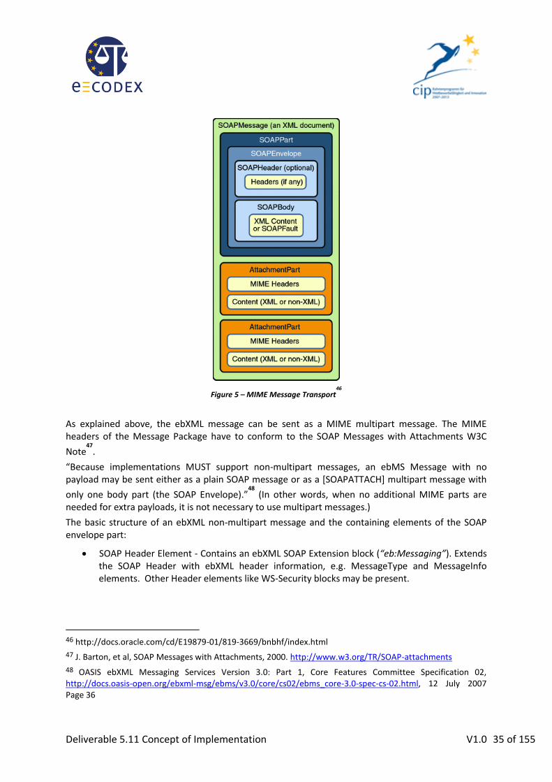
Deliverable 5.11 Concept of Implementation V1.0 35 of 155
Figure 5 – MIME Message Transport46
As explained above, the ebXML message can be sent as a MIME multipart message. The MIME headers of the Message Package have to conform to the SOAP Messages with Attachments W3C
Note47
.
“Because implementations MUST support non-multipart messages, an ebMS Message with no payload may be sent either as a plain SOAP message or as a [SOAPATTACH] multipart message with
only one body part (the SOAP Envelope).”48
(In other words, when no additional MIME parts are needed for extra payloads, it is not necessary to use multipart messages.)
The basic structure of an ebXML non-multipart message and the containing elements of the SOAP envelope part:
SOAP Header Element - Contains an ebXML SOAP Extension block (“eb:Messaging”). Extends the SOAP Header with ebXML header information, e.g. MessageType and MessageInfo elements. Other Header elements like WS-Security blocks may be present.
46 http://docs.oracle.com/cd/E19879-01/819-3669/bnbhf/index.html
47 J. Barton, et al, SOAP Messages with Attachments, 2000. http://www.w3.org/TR/SOAP-attachments
48 OASIS ebXML Messaging Services Version 3.0: Part 1, Core Features Committee Specification 02, http://docs.oasis-open.org/ebxml-msg/ebms/v3.0/core/cs02/ebms_core-3.0-spec-cs-02.html, 12 July 2007 Page 36

Deliverable 5.11 Concept of Implementation V1.0 36 of 155
SOAP Body Element - “Unlike ebMS v2, ebXML Messaging 3.0 does not define or make use of any elements within the SOAP Body, which is wholly reserved for user-specified payload
data.”49
In case of sending a multipart message, the SOAP message including the ebMS header is the root body part of the message (see Figure 6). In addition to the SOAP Body and the included user-specified payload, other Payload Containers may be present in the message package. There can also be additional MIME attachments that are not payload containers and which are outside the scope of the MSH processing (see Figure 5).
3.3.2. Message Structure
A detailed description of the XML structure of an ebXML Message can be found in the ebMS Core
Specification.50
The eb:Messaging structure inside the SOAP Header can carry either a UserMessage or a SignalMessage structure.
3.3.2.1. UserMessage
Figure 6 – SOAP Message with UserMessage51
49 OASIS ebXML Messaging Services Version 3.0: Part 1, Core Features Committee Specification 02, http://docs.oasis-open.org/ebxml-msg/ebms/v3.0/core/cs02/ebms_core-3.0-spec-cs-02.html, 12 July 2007 Page 38
50 OASIS ebXML Messaging Services Version 3.0: Part 1, Core Features Committee Specification 02, http://docs.oasis-open.org/ebxml-msg/ebms/v3.0/core/cs02/ebms_core-3.0-spec-cs-02.html, 12 July 2007 Chapter 5
51 OASIS ebXML Messaging Services Version 3.0: Part 1, Core Features Committee Specification 02, http://docs.oasis-open.org/ebxml-msg/ebms/v3.0/core/cs02/ebms_core-3.0-spec-cs-02.html, 12 July 2007 Page 34

Deliverable 5.11 Concept of Implementation V1.0 37 of 155
The above figure shows the general message structure of an ebMS UserMessage. The different parts of the UserMessage element are shown in the picture below.
Figure 7 – UserMessage Structure
3.3.2.2. SignalMessage

Deliverable 5.11 Concept of Implementation V1.0 38 of 155
Figure 8 – SOAP Message with SignalMessage52
The above figure shows the general message structure of an ebMS SignalMessage. The different parts of the SignalMessage element are shown in the picture below.
Figure 9 – SignalMessage Structure
3.3.3. Usage of ebMS in a Four-Corner-Model
In the European transport infrastructure different domains using proprietary standards are connected via Gateways, and a common protocol is required only between those Gateways.
In this type of architecture (also known as a Four-Corner-Model53) some additional agreements beyond what is already specified in the ebMS standard are required, as described in the following sections.
52 OASIS ebXML Messaging Services Version 3.0: Part 1, Core Features Committee Specification 02, http://docs.oasis-open.org/ebxml-msg/ebms/v3.0/core/cs02/ebms_core-3.0-spec-cs-02.html, 12 July 2007 Page 35
53 It is called a „Four-Corner-Model“ because a message passes four „corners“ on its way: the original sender, the sending gateway/access point, the receiving gateway/access point and the final recipient.

Deliverable 5.11 Concept of Implementation V1.0 39 of 155
Figure 10 – Four-Corner-Model 54
Note that these sections also cover profiling aspects. Relevant P-Mode settings are listed in Appendix III – P-Mode Configuration.
3.3.3.1. Addressing
In the usual scenarios where the ebMS protocol is used between end entities, it is obvious that the From and To fields in the UserMessage will be used for the sender and receiver respectively. However in a four-corner-model (i.e., an architecture that uses Gateways to connect existing proprietary infrastructures) the senders / recipients of ebMS messages are the Gateways, not the end entities.
In order to keep the option open to use out-of the box messaging products, From/PartyId and To/PartyId shall therefore in this case denote the addresses of Gateways.
The addresses of end entities will then be transmitted as ebMS properties.
An example is given in “B2B Protocols for Multi-Corner Message Exchange”55 <eb3:UserMessage>
<eb3:MessageInfo>
<!-- Omitted -->
</eb3:MessageInfo>
<eb3:PartyInfo>
<eb3:From>
<eb3:PartyId>http://edelivery.de/gateway</eb3:PartyId>
<eb3:Role>http://docs.oasis-open.org/ebxml-msg/ebms/v3.0/ns/core/200704/initiator</eb3:Role>
</eb3:From>
<eb3:To>
<eb3:PartyId>http://edelivery.nl/gateway</eb3:PartyId>
<eb3:Role>http://docs.oasis-open.org/ebxml-msg/ebms/v3.0/ns/core/200704/responder</eb3:Role>
</eb3:To>
</eb3:PartyInfo>
<eb3:CollaborationInfo>
<eb3:Service>http://docs.oasis-open.org/ebxml-msg/as4/200902/service</eb3:Service>
<eb3:Action>http://docs.oasis-open.org/ebxml-msg/as4/200902/action</eb3:Action>
54 PEPPOL Transport Architecture, http://www.peppol.eu/events/peppol-conferences/conference-pan-european-eprocurement-with-peppol/Conference%20Presentations/20091022-peppol-conference-3-architecture-overview-fremantle/view
55 http://www.oasis-open.org/committees/document.php?document_id=43769&wg_abbrev=bdx

Deliverable 5.11 Concept of Implementation V1.0 40 of 155
<eb3:ConversationId>ecae53d4-7473-45a6-ad70-61970dd7c4b0</eb3:ConversationId>
</eb3:CollaborationInfo>
<eb3:MessageProperties>
<eb3:Property
name="FromPartyId">123456789</eb3:Property>
<eb3:Property
name="ToPartyId">192837465</eb3:Property>
</eb3:MessageProperties>
<eb3:PayloadInfo>
<eb3:PartInfo />
</eb3:PayloadInfo>
</eb3:UserMessage>
3.3.3.1.1. Mapping of address entities between SBDH and ebMS Header
Every business document exchanged via e-CODEX includes also an Standard Business Document Header (SBDH) defining the main parameters of the business document including an ID, a timestamp of the creation of the document and of course also the ID’s of the sender and the recipient of the document. Due to the fact that the SBDH definition is an UN/CEFACT Standard including a big variety of possible and optional fields not all of them are used for e-CODEX. Below you can see the structure and as well the fields (highlighted) which are used by the e-CODEX transport platform. <sbdh:StandardBusinessDocumentHeader>
<sbdh:HeaderVersion>1.0</sbdh:HeaderVersion>
- <sbdh:Sender>
<sbdh:Identifier>R123456</sbdh:Identifier> // e.g. Austrian “ERV” Address of
the lawyer
- <sbdh:ContactInformation>
<sbdh:Contact>Albert Advokat</sbdh:Contact>
<sbdh:ContactTypeIdentifier>Claimant</sbdh:ContactTypeIdentifier>
</sbdh:ContactInformation>
</sbdh:Sender>
- <sbdh:Receiver>
<sbdh:Identifier>008</sbdh:Identifier> // ID of the Court
- <sbdh:ContactInformation>
<sbdh:Contact>Oberlandesgericht Wien</sbdh:Contact>
<sbdh:ContactTypeIdentifier>Decider</sbdh:ContactTypeIdentifier>
</sbdh:ContactInformation>
</sbdh:Receiver>
- <sbdh:DocumentIdentification>
<sbdh:Standard>e-CODEX</sbdh:Standard>
<sbdh:TypeVersion>1.0RC1</sbdh:TypeVersion>
<sbdh:InstanceIdentifier>[email protected]</sbdh:InstanceIdentifi
er> // ID of the message
<sbdh:Type>ApplicationForEPO</sbdh:Type>
<sbdh:CreationDateAndTime>2012-01-04T18:13:51.0Z</sbdh:CreationDateAndTime> //
Time of the receipt of the message
</sbdh:DocumentIdentification>
- <sbdh:BusinessScope>
- <sbdh:Scope>
<sbdh:Type>European regulation No.1896/2006</sbdh:Type>
<sbdh:InstanceIdentifier>00ebf4f7-ede3-4dbc-b95c-
a61c255b9d92</sbdh:InstanceIdentifier>
<sbdh:Identifier>PModeId</sbdh:Identifier>
- <sbdh:BusinessService>
<sbdh:BusinessServiceName>urn:ebv:services:EPO:0:4</sbdh:BusinessServiceName>
<sbdh:ServiceTransaction TypeOfServiceTransaction="RequestingServiceTransaction"
IsApplicationErrorResponseRequested="true" IsAuthenticationRequired="true"
IsIntelligibleCheckRequired="true" IsNonRepudiationOfReceiptRequired="true"
IsNonRepudiationRequired="true" Recurrence="2" TimeToAcknowledgeAcceptance=""
TimeToAcknowledgeReceipt="PT6H" />
</sbdh:BusinessService>
</sbdh:Scope>

Deliverable 5.11 Concept of Implementation V1.0 41 of 155
</sbdh:BusinessScope>
</sbdh:StandardBusinessDocumentHeader>
Depending on the national implementations the fields of the SBDH are filled in at the national connector or at the national application (e.g. EPO or Small Claims). Every field filled out, which is not highlighted, is optional and depends on the national implementation.
Note: The above highlighted fields are necessary for the transport of messages between GW’s and national connectors. It might be necessary that for future pilots additional optional fields are necessary from a business process point of view. But these additional fields are not used by the transport deliverables of WP5 and therefore not described here.
3.3.3.2. AS4 Reliability
The goal of AS4 reliability is to unburden the producer and the consumer of user messages of recoverable errors. This is done through a mechanism that ensures guarantees exact-once-delivery of user messages. The key features are:
Guaranteed delivery (providing at-least-once semantics)
Duplicate elimination (providing at-most-once semantics)
Keeping track of user message retransmissions
Customizability for each use case and each endpoint-to-endpoint setup (see Appendix III – P-Mode Configuration).
Compatibility to existing P-Modes and other existing MSH installations: The AS4 reliability feature is disabled by default.
{{
{
Sending MSHSending MSH Receiving MSHReceiving MSH
User MessageUser Message
ReceiptReceipt
interval
interval
for the user message
for the user message
User MessageUser Message
ReceiptReceipt
1st retransmission
2nd retransmission
interval
User MessageUser MessageInitial transmission
failure
User MessageUser Message
ready for delivery
User MessageUser Message
duplicate elimination
ReceiptReceipt
ReceiptReceipt
Figure 11 – Using retransmissions and duplicate elimination
3.3.3.2.1. Retransmissions and Time Schedule
Figure 11 shows the use of retransmissions and duplicate elimination:

Deliverable 5.11 Concept of Implementation V1.0 42 of 155
retry interval retry interval retry interval shutdown interval
Initial transmission
1 stretransm
ission
2 ndretransm
ission
3 rdretransm
ission
finally missing receipt
Figure 12 – The Sending MSH Time Schedule
Time schedules govern the process of transmitting and retransmitting user messages. The Gateway instantiates a time schedule for each user message. Fehler! Verweisquelle konnte nicht gefunden werden.Fehler! Verweisquelle konnte nicht gefunden werden. shows an exemplar of a time schedule with at most three retransmissions of a user message.
Scenario 1: Successful transmission of the user message and successful transmission of the receipt
The sending MSH transmits the user message and starts its time schedule.
The sending MSH waits one “retry interval” for a receipt that can be assigned to the user message. The receipt contains a reference to the user message ID.
If the sending MSH does not receive a receipt for the user message, it retransmits the user message (with identical message ID) and again waits one “retry interval” for a receipt. It continues to do so until a receipt is being received – or until the maximum number of retries is exhausted, whatever comes first.
The receiving MSH generates a receipt after receiving the user message. Then, it transmits the receipt to the sending MSH. This may fail. Technically, the receipt is embedded into a signal message. In this scenario, the receiving MSH successfully transmits the receipt to the sending MSH. It acknowledges each reception of a user message with a receipt. It eliminates duplicate receptions of the same user message resting upon its message ID.
The sending MSH receives the signal message that contains the receipt and a reference to the corresponding user message ID. The sending MSH ignores any subsequent receipts for this user message.
The sending MSH stops the user message’s time schedule. Therefore, it will not retransmit the user message again.
The sending MSH ascertains that the user message has been received by the receiving MSH.
Scenario 2: Successful transmission of the user message but no receipt
The sending MSH transmits the user message and starts its time schedule.
If the receiving MSH receives the user message, it generates a receipt and transmits it to the sending MSH. This may fail. In this scenario, the receiving MSH does not transmit a receipt to the sending MSH due to misconfiguration or due to some networking error.
One “retry interval” passes and there is no receipt for the user message in the meantime.
The sending MSH retransmits the user message (with identical message ID) and again waits one “retry interval” for a receipt. It continues to do so until it retransmits the user message for the last time according to the time schedule.

Deliverable 5.11 Concept of Implementation V1.0 43 of 155
After the final retransmission of the user message according to the time schedule, the sending MSH waits a final “shutdown interval” for the receipt.
After the final “shutdown interval” passes without receiving the user message’s receipt, the sending MSH finishes the user message’s time schedule. Therefore, it will not retransmit the user message again.
The sending MSH ascertains that it did not receive a receipt for the user message. This is an unrecoverable error in respect to the user message.
Scenario 3: Successful transmission of the user message but an error condition at the receiving MSH
The sending MSH transmits the user message and starts its time schedule.
In this scenario, the receiving MSH cannot handle the user message for some unexpected reason, e. g. because the SOAP message it is not well-formed XML. Therefore, the receiving MSH does not generate a receipt. It rather generates an error message and transmits it to the sending MSH. Technically, the error message is embedded into a signal message.
The sending MSH receives the signal message that references the user message and contains at least one error message.
The sending MSH stops the user message’s time schedule. Therefore, it will not retransmit the user message again.
The sending MSH ascertains that it did receive at least one error message for the user message. This is an unrecoverable error in respect to the user message.
Scenario 4: Failure to transmit the user message
The sending MSH fails to transmit the user message due to some networking error. It considers this to be a recoverable error since it may be possible to transmit the user message at a later time. It starts the user message’s time schedule since the failure to transmit the message counts as one (re)try.
After one “retry interval”, the sending MSH again tries to transmit the user message (with identical message ID). It pauses for the next “retry interval”, even if it repeatedly fails to send the user message. It continues to do so until it tries to transmit the user message for the last time according to the time schedule.
After finally trying to transmit the user message according to the time schedule, the sending MSH pauses for a final “shutdown interval” before it finishes the user message’s time schedule. Then, it will not try again to retransmit the user message.
The sending MSH ascertains an unrecoverable error in respect to the user message.
A mixture of the above scenarios may arise in practice. Figure 11 shows a mixed scenario.
Firstly, the sending MSH fails to send the user message due to some recoverable networking error (cf. Scenario 4).
Then, it successfully retries to transmit the user message. The receiving MSH generates and transmits a receipt. The sending MSH does not receive the receipt in time due to high network latency (cf. Scenario 2).
Finally, the sending MSH retransmits the user message again and receives the receipt (cf. Scenario 1). The receiving MSH acknowledges the user message with a second receipt since it cannot determine if the sending MSH has received the first receipt. The sending MSH ignores this second receipt.
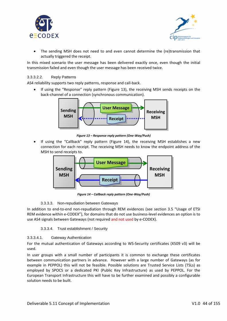
Deliverable 5.11 Concept of Implementation V1.0 44 of 155
The sending MSH does not need to and even cannot determine the (re)transmission that actually triggered the receipt.
In this mixed scenario the user message has been delivered exactly once, even though the initial transmission failed and even though the user message has been received twice.
3.3.3.2.2. Reply Patterns
AS4 reliability supports two reply patterns, response and call-back.
If using the “Response” reply pattern (Figure 13), the receiving MSH sends receipts on the back-channel of a connection (synchronous communication).
ReceivingMSH
ReceivingMSH
User MessageUser Message
ReceiptReceipt
SendingMSH
SendingMSH
Figure 13 – Response reply pattern (One-Way/Push)
If using the “Callback” reply pattern (Figure 14), the receiving MSH establishes a new connection for each receipt. The receiving MSH needs to know the endpoint address of the MSH to send receipts to.
ReceivingMSH
ReceivingMSH
User MessageUser Message
ReceiptReceipt
SendingMSH
SendingMSH
Figure 14 – Callback reply pattern (One-Way/Push)
3.3.3.3. Non-repudiation between Gateways
In addition to end-to-end non-repudiation through REM evidences (see section 3.5 “Usage of ETSI REM evidence within e-CODEX”), for domains that do not use business-level evidences an option is to use AS4 signals between Gateways (not required and not used by e-CODEX).
3.3.3.4. Trust establishment / Security
3.3.3.4.1. Gateway Authentication
For the mutual authentication of Gateways according to WS-Security certificates (X509 v3) will be used.
In user groups with a small number of participants it is common to exchange these certificates between communication partners in advance. However with a large number of Gateways (as for example in PEPPOL) this will not be feasible. Possible solutions are Trusted Service Lists (TSLs) as employed by SPOCS or a dedicated PKI (Public Key Infrastructure) as used by PEPPOL. For the European Transport Infrastructure this will have to be further examined and possibly a configurable solution needs to be built.

Deliverable 5.11 Concept of Implementation V1.0 45 of 155
For the e-CODEX pilots, having a limited number of Gateways, the out-of-the box available mechanisms for import of certificates will be used56. Member states choose their own certificates and exchange them out-of-band, i.e. by means outside e-CODEX infrastructure.
3.3.3.4.2. End Entity Authentication (Original Sender)
Before submitting messages users may have to authenticate themselves to either a national transport solution or to the European e-Justice Portal. The type and level of authentication required varies in each case. For the European e-Justice Portal it is anticipated that this authentication is done via users‘ STORK IDs, and also for other services such as national transport infrastructures it is to be expected that over time standardized authentication mechanisms will be used and that proof of this authentication should be submitted to the receiving Gateway as part of the message.
Both PEPPOL and SPOCS have therefore devised means to transmit a SAML57
token for end entity authentication in their messaging.
56 Note that the SPOCS TSL implementation is already available for reuse, so combining this with the e-CODEX solution will likely not be too difficult.
57 Assertions and Protocols for the OASIS Security Assertion Markup Language (SAML) V2.0, OASIS Standard, 15 March 2005, http://docs.oasis-open.org/security/saml/v2.0/saml-core-2.0-os.pdf

Deliverable 5.11 Concept of Implementation V1.0 46 of 155
Figure 15 – SAML Assertion
For the European Transport Infrastructure, this SAML token may be added as a separate message part.
For which business exchanges this type of special payload is required, can be configured in the
BusinessInfo.PayloadProfile setting of the P-Mode. (That is, communication partners can in this setting agree upon whether they need the SAML token or not.) When it is not present, no SAML token, will be used.
For the e-CODEX piloting, in the first stage no SAML tokens will be required.
The PayloadInfo element of the ebMS UserMessage structure will then contain a corresponding PartInfo structure referencing this additional message part, and the messages parts will be required to appear in a given order (see section 0 “It has been decided in e-CODEX WP4 that the so-called “Trust-OK token” (which gives information about signature verification and/or user authentication in human-readable form) should be packaged together with the signed documents in a container.

Deliverable 5.11 Concept of Implementation V1.0 47 of 155
Therefore the whole container is just one attachment. The XML version of the “Trust-OK token”, which is not packaged, will be treated similar to the SAML token as a separate message part.
Summary: Message parts” below).
Figure 16 – PartInfo in the UserMessage
Example:
<eb3:UserMessage>
<eb3:MessageInfo>
<!-- Omitted -->
</eb3:MessageInfo>
<eb3:PartyInfo>
<eb3:From>
<!-- Omitted -->
</eb3:From>
<eb3:To>
<!-- Omitted -->
</eb3:To>
</eb3:PartyInfo>
<eb3:CollaborationInfo>
<!-- Omitted -->
</eb3:CollaborationInfo>
<eb3:PayloadInfo>
<eb3:PartInfo>
<eb3:Description>XML business document in SOAP body</eb3:Description>
</eb3:PartInfo>
<eb3:PartInfo href="cid:[email protected]">
<eb3:Description>SAML Token</eb3:Description>
</eb3:PartInfo>
</eb3:PayloadInfo>
<!— Other payloads -->
</eb3:UserMessage>
A profile for the SAML token is given in Appendix I – SAML Token Profile.
Example:
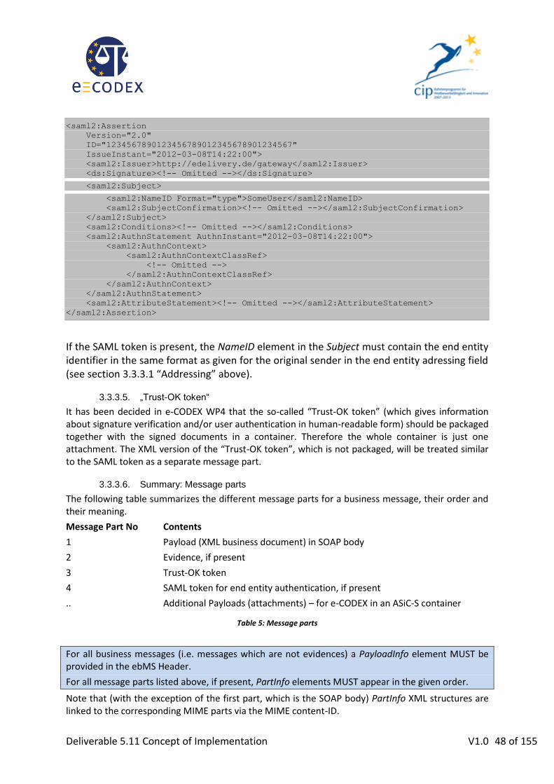
Deliverable 5.11 Concept of Implementation V1.0 48 of 155
<saml2:Assertion
Version="2.0"
ID="1234567890123456789012345678901234567"
IssueInstant="2012-03-08T14:22:00">
<saml2:Issuer>http://edelivery.de/gateway</saml2:Issuer>
<ds:Signature><!-- Omitted --></ds:Signature>
<saml2:Subject>
<saml2:NameID Format="type">SomeUser</saml2:NameID>
<saml2:SubjectConfirmation><!-- Omitted --></saml2:SubjectConfirmation>
</saml2:Subject>
<saml2:Conditions><!-- Omitted --></saml2:Conditions>
<saml2:AuthnStatement AuthnInstant="2012-03-08T14:22:00">
<saml2:AuthnContext>
<saml2:AuthnContextClassRef>
<!-- Omitted -->
</saml2:AuthnContextClassRef>
</saml2:AuthnContext>
</saml2:AuthnStatement>
<saml2:AttributeStatement><!-- Omitted --></saml2:AttributeStatement>
</saml2:Assertion>
If the SAML token is present, the NameID element in the Subject must contain the end entity identifier in the same format as given for the original sender in the end entity adressing field (see section 3.3.3.1 “Addressing” above).
3.3.3.5. „Trust-OK token“
It has been decided in e-CODEX WP4 that the so-called “Trust-OK token” (which gives information about signature verification and/or user authentication in human-readable form) should be packaged together with the signed documents in a container. Therefore the whole container is just one attachment. The XML version of the “Trust-OK token”, which is not packaged, will be treated similar to the SAML token as a separate message part.
3.3.3.6. Summary: Message parts
The following table summarizes the different message parts for a business message, their order and their meaning.
Message Part No Contents
1 Payload (XML business document) in SOAP body
2 Evidence, if present
3 Trust-OK token
4 SAML token for end entity authentication, if present
.. Additional Payloads (attachments) – for e-CODEX in an ASiC-S container
Table 5: Message parts
For all business messages (i.e. messages which are not evidences) a PayloadInfo element MUST be provided in the ebMS Header.
For all message parts listed above, if present, PartInfo elements MUST appear in the given order.
Note that (with the exception of the first part, which is the SOAP body) PartInfo XML structures are linked to the corresponding MIME parts via the MIME content-ID.

Deliverable 5.11 Concept of Implementation V1.0 49 of 155
Example:
Content-Type: Multipart/Related; boundary=MIME_boundary;
type=application/soap+xml;
start="<[email protected]>"
--MIME_boundary
Content-Type: application/soap+xml; charset=UTF-8
Content-Transfer-Encoding: 8bit
Content-ID: <[email protected]>
<?xml version='1.0' ?>
<S12:Envelope xmlns:S12="http://www.w3.org/2003/05/soap-envelope"
xmlns:eb="http://docs.oasis-open.org/ebxml-msg/ebms/v3.0/ns/core/200704/">
<S12:Header>
<eb:Messaging S12:mustUnderstand="true">
<!-- ... -->
<eb:PayloadInfo>
<eb:PartInfo>
<eb:Description>Actual business document payload</eb:Description>
</eb:PartInfo>
<eb:PartInfo href="cid:2baedf50-8736-11e1-b0c4-0800200c9a66">
<eb:Description>SAML Token</eb:Description>
</eb:PartInfo>
<eb:PartInfo href="cid:f4f8b7f0-8736-11e1-b0c4-0800200c9a66">
<eb:Description>Additional attachment</eb:Description>
</eb:PartInfo>
</eb:PayloadInfo>
</eb:Messaging>
</S12:Header>
<S12:Body>
<eCODEX:EPO>
<!-- ... -->
</eCODEX:EPO>
</S12:Body>
</S12:Envelope>
--MIME_boundary
Content-Type: application/samlassertion+xml
Content-Transfer-Encoding: 8bit
Content-ID: <cid:[email protected]>
<?xml version='1.0' ?>
<saml2:Assertion
Version="2.0"
ID="1234567890123456789012345678901234567"
IssueInstant="2012-03-08T14:22:00">
<!-- ... -->
</saml2:Assertion>
--MIME_boundary
Content-Type: image/tiff
Content-Transfer-Encoding: binary
Content-ID: <cid:[email protected]>
...scanned document binary...
--MIME_boundary--
3.3.3.7. Message Exchange Patterns
In general, the simplest way to send a message is by making an HTTP request, so implementations are expected to support (One-Way) push mode at minimum. If both Gateways support being sender and receiver in this pattern, the Two-Way/Push-and-Push pattern technically poses no extra challenges. On the logical level it introduces the possibility to have messages related to each other, that is, to implement question- and-answer scenarios.

Deliverable 5.11 Concept of Implementation V1.0 50 of 155
Pulling patterns are primarily useful for communication partners with limited capabilities (for example mobile devices which cannot act as HTTP servers). Therefore Member states might choose to use these features to implement lightweight clients as backend interfaces, however for interoperability between Gateways it will not be required58.
e-CODEX Gateways will support a least the One-Way/Push.
3.3.4. Open issues
For the following topics a solution is described for e-CODEX within this deliverable but they will need further elaboration, if used outside e-CODEX. Therefore a discussion is needed within the European e-Delivery Task Force:
Addressing of End Entities, Address format
Dynamic Discovery (see also the following section)
Trust establishment
Evidences (end-to-end, further profiling)
3.4. Discovery, addressing and endpoint capabilities
To send an electronic message from sender to receiver address resolution or routing is needed. In order to enable routing of documents received from the sender to the correct recipient the messages will have to be routed using the already existing e-Delivery solutions of the Member States.
58 Note that the AS4 profile requires support for the One-Way/Pull MEP as well. Even so, obviously any AS4-compliant implementation would still satisfy the e-CODEX requirements.

Deliverable 5.11 Concept of Implementation V1.0 51 of 155
Infrastructure of
receiver realm
MS-B
Infrastructure of
sender realm
MS-A
Interoperability
layer
Send
message to
public agency
MS-B
Receive
message from
public agency
MS-A
Public agency
MS-A
Public agency
MS-B
1: Forward message
to gateway of
sender realm
2: Lookup metadata
and address and forward
message to gateway of
receiver realm
(or transparent
intermediary)
Transform message
to “MS-B format”
Transform message
to “EU format”
3. Optional
transparent intermediary:
Forward message
4: Deliver message
within receiver realm
Figure 17 – Message routing
In this case the list of participants is numerous. For example, in Romania alone the number of courts is well above 400. So we can safely assume that a sending party has no knowledge of all existing recipients in all the 27 Member States, let alone knows the details for routing between the different infrastructures that are needed for cross-border messaging. Therefore it is preferable to have a dynamic system to discover the corresponding Gateways and whether they are capable of receiving the message including the metadata for document type. Part of the solution to discover partner Gateways and their capabilities can be found in the service discovery process of PEPPOL.

Deliverable 5.11 Concept of Implementation V1.0 52 of 155
Figure 18 – Discovery infrastructure
The Gateways communicate in a peer-to-peer like model across the internet and discover partner Gateways and their routing addresses via the SML/SMP infrastructure.
3.4.1. Service Metadata Locator (SML)
For a sender, the Discovery process begins with the establishment of the location of the Service Metadata relating to the particular Gateway to which the sender wants to transmit a message. Each participant can be a sender and a recipient and is identified by Participant ID. A Participant ID is a unique identifier of a particular participant. Here it is assumed that the sender knows the identity of the intended recipient end entity. If the identity is not known, it can be found using mechanisms described in chapter 6.
The metadata locator concept is explained in the PEPPOL Specification “PEPPOL Transport
Infrastructure Service Metadata Locator (SML)”59
:
“The Service Metadata Locator service specification is based on the use of DNS (Domain Name
System) lookups to find the address of the Service Metadata for a given participant ID [DNS-103460
]
[DNS-103561
]. This approach has the advantage that it does not need a single central server to run the Discovery interface, with its associated single point of failure.”
The following diagram represents the lookup flow.
59 https://joinup.ec.europa.eu/svn/peppol/PEPPOL_EIA/1-ICT_Architecture/1-ICT-Transport_Infrastructure/13-ICT-Models/ICT-Transport-SML_Service_Specification-101.pdf 60
http://www.ietf.org/rfc/rfc1034.txt
61 http://www.ietf.org/rfc/rfc1035.txt

Deliverable 5.11 Concept of Implementation V1.0 53 of 155
Figure 19 – Endpoint lookup with Service Metadata
Each participant can be a sender and a recipient and is identified by Participant ID. A Participant ID is a unique identifier of a particular participant. Note that these identifiers identify end entities, not the service providers handling messages on their behalf.
The SML service itself plays the role of providing controlled access to the creation and update of entries in the DNS. The sender constructs the address for the service metadata for a given recipient participant identifier using a standard format, as follows:
http://<hash over recipientID>.<schemeID>.<SMLdomain>/<recipientID>/services/<documentType>
Each participant ID gets a unique URL for its Metadata. SML uses the CNAME record type and constructs domain names using the following scheme:
< hash over recipientID>.<schemeID>.<SML domain>
Via DNS lookup this domain name resolves to the domain name of the Metadata Publisher server, which is defined in the SMP specification.
3.4.2. BDX Metadata Service Location
As part of its sustainability efforts, PEPPOL has submitted SML and its other technical specifications to OASIS for further development and standardization in the Business Document Exchange (BDXR) technical committee. The functionality of SML is being subsumed in a more general technical specification called the Business Document Metadata Service Location. Like SML, this specification is based on DNS, but is based on a different type of DNS resource records called URI-enabled Naming Authority Pointer records (U-NAPTR)62, which are defined to support Dynamic Delegation Discovery Service (DDDS). In this approach, the result of a query is a full URI rather than just a canonical domain name. The URI can use HTTPS and support server authentication. Software implementations of this newer specification have been developed that successfully validate the specification.
62 Domain-Based Application Service Location Using URIs and the Dynamic Delegation Discovery Service (DDDS) https://tools.ietf.org/html/rfc4848

Deliverable 5.11 Concept of Implementation V1.0 54 of 155
3.4.3. Service Metadata Publisher (SMP)
The SMP specification complements SML (and the BDX metadata service location specification). It defines an XML-based service metadata data model and a REST binding to retrieve service metadata:
The Metadata Publisher hosts Metadata for each participant ID at a predefined URL63
/<recipientID>/services/<documentType>
The sender uses this URL in a HTTP GET operation which returns the metadata relating to that recipient and the specific document type (for details, see the Service Metadata
Publishing specification [BDEN-SMP]64
).
The sender can obtain the information necessary to transmit a message containing that document type to that recipient from the returned metadata. This sequence is shown in the following figure:
Figure 20 – Sequence Diagram for Sender transmitting Document to Recipient65
In order to enable routing of documents received from the sender to the correct recipient, the infrastructural information resides on servers called Service Metadata Publishers (SMPs). They store information about the receiving capabilities of participants connected to the network, provide the details about the business document types supported and the business collaboration profiles that can be processed through the infrastructure. SMP service metadata is a combination of information on the end entity recipient and the Gateway. For the end entity, it provides its identifier, supported business documents and the business processes in which it accepts those documents. For the Gateway, the metadata provides technical configuration information on the receiving endpoint, such as the transport protocol it uses and its address. The SMP data model has some extensibility options but assumes the number of technical configuration parameters of a transport protocol is fairly
63 The use of the recipientID in the path is redundant as it is already included in the domain name alias queried in SML, It is required because of SML's dependency on CNAME records. It is not needed in the BDX metadata service location.
64 https://joinup.ec.europa.eu/svn/peppol/PEPPOL_EIA/1-ICT_Architecture/1-ICT-Transport_Infrastructure/13-ICT-Models/ICT-Transport-SMP_Service_Specification-101.pdf
65 https://joinup.ec.europa.eu/svn/peppol/PEPPOL_EIA/1-ICT_Architecture/1-ICT-Transport_Infrastructure/13-ICT-Models/ICT-Transport-SML_Service_Specification-101.pdf

Deliverable 5.11 Concept of Implementation V1.0 55 of 155
limited, as is the case in PEPPOL's transport protocol START. The delegation of responsibility from end entity to Gateway is implicit in the SMP data model: service providers are anonymous and are not themselves represented explicitly.
Every network participant is being registered in only one SMP registry. The Gateway must identify the correct connection in order to retrieve the information about that specific recipient party. The Gateway then receives the document and forwards it to the receiving Gateway that will send an acknowledgement and pass it on to the recipient.
SMP cannot be used to obtain configuration information that pertains to the sender rather than the receiver. For example, it is not possible to use SMP to discover the certificate a sender would use to sign its messages. In PEPPOL this information is not needed as PEPPOL endpoints are using certificates issued by a dedicated CA. The START protocol includes a profiling of WS-Security, in which receiving endpoints are expected to trust any message signed using any certificates issued by this CA.
In the PEPPOL architecture, SML and SMP function as a registry of end entities. In a model where Gateways are not anonymous but have identifiers themselves, as in the ebMS 3.0 profiling defined in section 3.3, it is conceivable to use SML/SMP to store information on Gateways directly rather than end entities, and no changes would be needed to either of the two specifications. This alternative may be appropriate for situations where the relation between end entity and Gateway is predictable or handled in a different manner. Relations between end entities and Gateways are predictable in e-CODEX, as the sender knows which member state the end entity is in and there is required to be only one Gateway per member state. This is a difference with PEPPOL, where there is an open market of Gateway service providers and end entities may migrate from one service provider to another.
3.4.4. Processing Modes, CPPs and CPAs
As explained above, Processing Modes or P-Modes are introduced in ebMS 3.0 to define the configuration for ebMS 3.0 Message Handlers. P-Modes are necessary if you want to set up an agreement between two partners as to how messages must be processed, on both the sending and receiving sides. Both partners must be able to associate the same P-Mode with a message for consistent processing (e.g. security, reliability, encryption, signing). So before a message is sent, the sender must be able to determine which P-Mode is used for this message. The receiver must have a matching P-Mode configured. The ebMS 3.0 and AS4 specifications do not preclude endpoints from configuring processing modes dynamically, on demand, or from supporting wildcard values for some parameters. For example, a wildcard value for PMode.Initiator.Party would allow a receiving message handler to process messages from any sender. Such functionality would, however, be product-specific. At the time of writing, such functionality does not seem to be supported in emerging ebMS 3.0 products.
In ebMS 3 the message-exchange capabilities of a party are thus expressed as a set of P-Modes. In a more general context, this concept is called a Collaboration-Protocol Profile (CPP). The OASIS
Collaboration-Protocol Profile and Agreement Specification66
describes a CPP as follows:
“A CPP defines the capabilities of a Party to engage in electronic Business with other Parties. These capabilities include both technology capabilities, such as supported communication and messaging protocols, and Business capabilities in terms of what Business Collaborations it supports.”
66 OASIS, Collaboration-Protocol Profile and Agreement Specification Version 2.0, http://www.oasis-open.org/committees/ebxml-cppa/documents/ebcpp-2.0.pdf
Deliverable 5.11 Concept of Implementation V1.0 56 of 155
An agreement between two parties can be described by a Collaboration-Protocol Agreement (CPA). A CPA is therefore composed of the CPPs that the parties use, or of the P-Modes they have configured.
Examples of both CPPs and CPAs can be found in the Collaboration-Protocol Profile and Agreement Specification. The current version 2.0 ebXML CPPA OASIS Standard supports the earlier version 2.0 of ebXML Messaging. An updated version 3.0 specification that supports ebMS 3.0 and other messaging protocols is under development in the OASIS ebCore Technical Committee but is not yet finished. The SMP service metadata XML structures are very similar to the ebXML Collaboration Protocol Profile (CPP). A CPP defines what can be sent and what can be received while SMP only defines the messages a participant can receive.
Since the ebMS standard does not specify the way that configuration information is retrieved (and, as mentioned above, the Collaboration Agreement reference in ebMS 3.0 messages can point to something different from a CPA), implementations are very much free to decide how to handle this. On interoperability this decision has little or no impact.
3.4.5. SMP and Processing Modes
The SMP data model and the ebMS 3.0 P-Modes can be compared at the level of the elements in the SMP XML schema and the individual parameters in the abstract P-Mode model. A key difference between SMP and P-Modes is that SMP is only concerned with the receiving endpoint; it does not configure the sending endpoint.
Many core P-Mode parameters can be mapped to corresponding elements in SMP. For example, the BusinessInfo.Service parameter can be mapped to ProcessIdentifier and Protocol.Address to EndpointReference/Address.
Parameters such as the sender party identifier and identifier type are missing in SMP. They could be addressed in ebMS 3.0 products that support a wildcard mechanism as mentioned above, allowing a receiving message handler to process messages from arbitrary senders.
SMP does not support configuration of sender or receiver roles. This could be addressed in an enhancement to the SMP schema or by requiring a profile of ebMS 3.0 that uses fixed (non-configurable) values.
In ebMS 3.0, it is possible for the sender to asynchronously receive message receipts or errors at a configured address. It could be decided to profile ebMS 3.0 so that endpoints only need to support synchronous receipts and errors. These parameters then are no longer configuration items.
SMP does not support configuration of sender certificates for signing, encryption or TLS, because of SMP's dependency on PEPPOL's concept of a dedicated PKI. In e-CODEX, a similar PKI model has not been adopted and member states are not required to use certificates issued by a project-specific Certificate Authority. Even if adopted, it is unclear if this PKI model would be supported by the ebMS 3.0 products used by the various member states.
In the ebMS 3.0 profiling defined in section 3.3, the ebMS 3.0 To party identifier identifies the receiving Gateway rather than the ultimate destination, which is encoded as a message property. SMP participants are end entities and Gateways are anonymous. The service Gateway used by a particular end entity may in some cases be inferred from the domain name in the endpoint address URI, but this is not required.
SMP has a few configuration elements for which ebMS 3.0 has no counterparts: Require Business Level Signature and Minimum Authentication Level.
PEPPOL has submitted its technical specifications, including SMP, to the OASIS BDXR Technical Committee for standardization. The committee is also working on standardizing a profile of ebMS 3.0

Deliverable 5.11 Concept of Implementation V1.0 57 of 155
for use in four corner models and has a work item to look at ways to use SML/SMP to retrieve configuration information for ebMS 3. Note that the eb:CollaborationInfo/eb:AgreementRef element in the ebMS UserMessage does not necessarily have to point to an instance of a CPA (though this is RECOMMENDED in the ebMS 3 specification) and is an optional element in the ebMS3 header.
3.4.6. Dynamic Discovery prototype in e-CODEX
For the e-CODEX pilots, the national Gateways are being configured statically using the configuration mechanisms of the ebMS 3.0 message handler products used by the various member states. The e-CODEX e-Delivery solution has a proprietary XML format for processing modes, which it loads at start-up but also periodically refreshes, making updated configurations available for use dynamically. It is possible to derive these XML configurations from other XML formats using XSLT stylesheets of other programs. A toolkit has been developed in e-CODEX to generate such Holodeck XML files. Anyway in order to support further LSP projects like e-SENS e-CODEX has developed a prototype to demonstrate how a Dynamic Discovery could be implemented.
As e-CODEX has no installed base of SML users, it is appropriate to directly adopt the DDDS-based Metadata Service Location specification under development in BDXR as basis for its own service discovery work.
As regards the service metadata publication protocol, a number of options can be considered:
1. SMP as designed by PEPPOL could be used as the format from which to generate product-specific configurations for Gateways, either indirectly when SMP registrations are used for end entities (as in the PEPPOL architecture and an option for e-CODEX) or when Gateways are non-anonymous and registered directly (as is an alternative option for e-CODEX).
The main obstacle to this is that SMP currently lacks some parameters including some important ones like the sender certificate. This option is only feasible if e-CODEX adopts a dedicated PKI model as in PEPPOL , updates Holodeck to support this model and member states that use other ebMS 3.0 products convince their suppliers to do so as well.
2. Alternatively, SMP could be used only as a registry of information relating end entity recipients to their Gateways only without requiring it to also contain all information needed to generate a complete P-Mode information set. Instead, it would be assumed that Gateways are configured using a different process (not involving SMP), and that the only requirement is that SMP data for end entities can be mapped to these configurations. This can be done without changes to SMP using ParticipantIdentifier, ProcessIdentifier, DocumentIdentifier and EndpointReference/Adress as key.
3. SMP could also be enhanced to address missing features so that ebMS 3.0 message handlers can be fully configured from SMP data. This depends on the willingness of the maintainers of SMP (currently the members of the OASIS BDXR Committee who serve as SMP editors and are part of the PEPPOL community) to make non-backwards compatible changes. These updates would take SMP very close to ebXML CPP. The standardization of these (and possibly other) emerging metadata formats and their take-up (or lack thereof) is an aspect to be monitored.
The second of these options is the most practical short term option. It has the lowest risk, requires few resources, has no dependencies external to e-CODEX, does not force e-CODEX to adopt a dedicated PKI and does not require changes to the SMP specification. The third option is the more attractive long term option and may be re-considered in the future (e.g. in e-SENS) once the

Deliverable 5.11 Concept of Implementation V1.0 58 of 155
standardization of metadata service locations and data models has progressed more and reached a higher degree of maturity.
3.5. Usage of ETSI REM evidence within e-CODEX For-non-repudiation purposes, e-CODEX is providing evidence according to the ETSI REM specification (ETSI TS 102 640-2)67.
This evidence carries a hash value over the message which can be verified both by sender and recipient, and is signed by the sending Gateway (or, more precisely, the corresponding e-CODEX connector, see below). Thus the sender can prove that his/her message has been received (non-repudiation of receipt) and the recipient can prove that the message he/she holds has indeed been received from that particular sender (non-repudiation of origin)..
At the same time, through the use of a timestamp, the evidence provides information about the different points in time when the message was received at the sender’s Gateway, then the recipient’s Gateway, and the national system on the receiving side68. This information is particularly relevant in view of statutory periods (deadlines) depending on the point in time of legally valid reception.
In order to be able to use out-of-the box ebMS implementations, which know nothing about REM, this evidence is generated within the e-CODEX connectors (see chapter 4 “Gateway”), which act as adapters to the proprietary national systems and provide all e-CODEX specific functionality that is outside the scope of off-the-shelf messaging products. REM evidence messages may therefore be considered as application-level messages; the evidence is transported as ordinary payload.
3.5.1. Evidence Types
Note that the names and XML elements are the same for positive and negative evidence (e.g. SubmissionAcceptanceRejection both for acceptance or rejection of a submission) – the
difference between the positive and the negative case is determined through the EventCode element (see section 3.5.3.1 “Event Codes” below).
In the following text the terms denoting the actual event will occasionally be used for better readability, e.g. SubmissionAcceptance meaning a SubmissionAcceptanceRejection with its EventCode set to Acceptance (http:uri.etsi.org/02640/Event#Acceptance).
The evidence elements used by e-CODEX are:
SubmissionAcceptanceRejection
RelayREMMDAcceptanceRejection
RelayREMMDFailure
DeliveryNonDeliveryToRecipient
RetrievalNonRetrievalByRecipient
67 ETSI TS 102 640-1 V2.2.1 (2011-09):
http://www.etsi.org/deliver/etsi_ts/102600_102699/10264001/02.02.01_60/ts_10264001v020201p.pdf
68 Though the European e-Justice Portal is not strictly speaking a „national system“, the situation is similar, since the e-CODEX gateway will be connected to the portal through the e-TrustEx infrastructure. This infrastructure then plays a role that is comparable to the one of the national systems mentioned in this document.

Deliverable 5.11 Concept of Implementation V1.0 59 of 155
The following table gives a short overview about the different evidences which are send depending whether the conditions (grey part) are true (T) or false (F).
Figure 21 –Evidence Overview
3.5.1.1. Acceptance at the sender’s Gateway
The first evidence (SubmissionAcceptance) is generated (in the connector) at the sender’s Gateway upon accepting a message from the national system. This evidence is sent to the recipient’s Gateway along with the message. The national system may generate an evidence message in its own proprietary format to send back to the original sender.
Failure of Acceptance (for Submission) at the sender’s Gateway leads to the corresponding negative Evidence (SubmissionRejection), which must be relayed back to the original sender. This situation can occur as a result of errors which lead to non-availability of the sender’s Gateway.
3.5.1.2. Acceptance at the recipient’s Gateway
When the message arrives at the recipient’s Gateway, an evidence message is sent back to the sender’s Gateway (RelayREMMDAcceptance). This evidence may be relayed to the original sender. (The decision is up to each Member State.)
Timeout for Acceptance (for RelayToREMMD) at the recipient’s Gateway leads to the corresponding negative Evidence (RelayREMMDFailure), which is generated at the sender’s Gateway and provided

Deliverable 5.11 Concept of Implementation V1.0 60 of 155
to the original sender. This situation can occur as a result of non-recoverable errors in case of non-availability of the recipient’s Gateway, when retries are either impossible or the foreseen number of retries has expired.
If the message reaches the recipient’s Gateway but is there not accepted (e.g. because content validation in the receiving side’s e-CODEX connector fails), the recipient’s Gateway generates a RelayREMMDRejection evidence and send it back to the sender’s Gateway. This rejection evidence must be relayed back to the original sender. The message will then not be forwarded to the ultimate recipient.
3.5.1.3. Delivery
After acceptance at the recipient’s Gateway the message will be forwarded to the national system on the receiving side. When this system sends a receipt (in proprietary format) back that the message has been delivered (usually to a mailbox in the national system), the connector at the recipient’s Gateway provides another type of evidence to the sender’s Gateway (Delivery – i.e.
DeliveryNonDeliveryToRecipient with its EventCode element set to Delivery (http:uri.etsi.org/REM/Event#Delivery)). This evidence must be relayed to the original sender. In most countries this is the evidence of legally valid delivery.
If a message couldn’t be delivered after a certain time, an expiration evidence message (i.e.
DeliveryNonDeliveryToRecipient with its EventCode set to DeliveryExpiration (http:uri.etsi.org/REM/Event#DeliveryExpiration) will be sent to the sender’s Gateway. This evidence must be relayed to the original sender. This is an error condition. The sender’s infrastructure should therefore insure that the sender is in this case aware that his documents have not been received.
If evidence of delivery is generally not available in the national system at the receiving side, an evidence message will be sent immediately by the connector at the receiving Gateway:
if acceptance at the Gateway can in that country be considered as legally valid, a (positive) delivery evidence will be sent, which must also be relayed to the original sender. This might for the piloting be the case where there is only one receiving court that is directly connected to the Gateway, or if the Gateway is otherwise directly connected to an application (usually a portal) that permits end users to retrieve messages. This also applies in particular to the European e-Justice portal.
If acceptance at the Gateway is not considered legally valid delivery, an expiration evidence message will be sent immediately. In this case the sender will have no proof of legally valid delivery. It is recommended that the connector at the sender’s Gateway, instead of relaying this expiration evidence, informs the sender that the message has been accepted by the Gateway but there is no proof of further delivery. Note that this is an unlikely case since it would imply that in the receiving country the national system is not capable of generating the type of evidence that would imply legally valid delivery in this country.
3.5.1.4. Retrieval
If the national system provides information about message retrieval to the recipient’s Gateway, and if in the receiving country this is the point in time of legally valid delivery, the recipient’s Gateway
sends an evidence message (retrieval – i.e. RetrievalNonRetrievalByRecipient with its EventCode set to Retrieval (http:uri.etsi.org/REM/Event#Retrieval)) to the sender’s Gateway. This evidence must be relayed to the original sender.

Deliverable 5.11 Concept of Implementation V1.0 61 of 155
Note that according to the Basic Conformance Profile69 described in ETSI TS 102 640-4 (section 4.6, p. 9), only Delivery evidence is mandatory, whereas Retrieval evidence is not required.
If the national system provides information about message retrieval to the recipient’s Gateway, and if in the receiving country this is the point in time of legally valid delivery, and if in this situation a message wasn’t be retrieved after a certain time, delivery expiration evidence (i.e.
RetrievalNonRetrievalByRecipient with EventCode NonRetrievalExpiration (http:uri.etsi.org/REM/Event#NonRetrievalExpiration) will be sent to the sender’s Gateway. This evidence must be relayed to the original sender.
If in a receiving country retrieval evidence is not used, delivery expiration evidence should in the sending country not be relayed to the original sender. In this case it is assured that the message may still have (and likely has been) received, only the system used in that country doesn’t generate the corresponding evidence. Therefore there is no proof of retrieval (only of delivery).
If the e-CODEX connector at the sending side does not provide the possibility to configure the forwarding of Retrieval evidence on a per-country basis, it is recommend to generally not forward retrieval expiration evidences to end users.
It is expected that most e-CODEX members (including the European e-Justice portal) do not use retrieval and retrieval expiration evidence.
For extended applications in the future the ability to produce certain types of evidence might be considered as an additional capability that can be discovered in the same way that other capabilities (technical capabilities of Gateways as well as business capabilities of end entities) are discovered (see section 3.4 “Discovery, addressing and endpoint capabilities”.
3.5.2. Message Envelope
e-CODEX messages (when they are not pure evidence messages) usually contain the following payloads
XML data corresponding to the forms of the particular business process (in the SOAP body)
a “Trust-OK token” in XML format
an ASiC-S-container with PDF documents and the associated signatures
evidence (in XML format) accompanying the original message which will be used for creating further evidence going back to the sender.
Pure evidence messages contain only evidence. For this type of message, the action parameter will be set to evidence, and upon receiving this type of message, no evidence will be sent back.
Evidence files are not put inside the ASiC-S-container.
69 ETSI TS 102 640-4 V2.1.1 (2010-01):
http://www.etsi.org/deliver/etsi_ts/102600_102699/10264004/02.01.01_60/ts_10264004v020101p.pdf

Deliverable 5.11 Concept of Implementation V1.0 62 of 155
3.5.3. Evidence Details
The XML implementation of the REM specification is described in ETSI TS 102 640-2, Annex B (p. 57). The different possible root elements that can occur in an actual evidence message (SubmissionAcceptanceRejection, RelayREMMDAcceptanceRejection,
RelayREMMDFailure) etc. are all of type REMEvidenceType.
Figure 22 –REMEvidenceType XML structure

Deliverable 5.11 Concept of Implementation V1.0 63 of 155
The following elements of the REMEvidenceType XML structure will be used by e-CODEX:
Element Content 1st evidence (sent with message)
Passed as a parameter from connector to evidence generator
rem:EventCode Acceptance, Rejection, Delivery, DeliveryExpiration, Retrieval, NonRetrievalExpiration
According to workflow
x
xrem:EventReasons Code, see ETSI TS 102 640-2, Appendix D
According to workflow
x
EvidenceIdentifier unique id for the evidence
Created in the evidence generator
rem:EvidenceIssuerDetails/
NamesPostalAdresses
Name of Gateway and Postal address of hosting organization
Configurable in connector
x
rem:EvidenceIssuerDetails/
ElectronicAddress
Electronic address (Gateway endpoint url)
Configurable in connector
x
EventTime Timestamp Created in the evidence generator
rem:SenderDetails Electronic address (in national system)
From national system
x
rem:RecipientsDetails Electronic address (in national system)
From national system
x
rem:SenderMessageDetails/
MessageIdentifierByREMMD
Message ID (national) From national system
x
rem:senderMessageDetails/
DigestMethod
rem:senderMessageDetails/
DigestValue
Hash Computed in connector
x
ds:Signature Signature on the evidence
Created in the evidence generator
Table 6: XML elements used by e-CODEX
For evidence messages going back from the receiving side to the sending side, most elements can be copied from that first evidence which is sent together with the message.

Deliverable 5.11 Concept of Implementation V1.0 64 of 155
Note however that for non-repudiation the hash value of the message should be computed independently by the recipient in order to acknowledge reception only for what has really been verified.
3.5.3.1. Event Codes
The element REMEvidenceType / eventCode allows to use the same evidence structure for success as well as failure message transmission.
The following values will be used within e-CODEX:
"http:uri.etsi.org/02640/Event#Acceptance": Acceptance of some REM Message by some entity. (Sender’s or Recipient’s Gateway)
"http:uri.etsi.org/02640/Event#Rejection": Rejection of some REM Message by some entity. (Sender’s or Recipient’s Gateway)
"http:uri.etsi.org/REM/Event#Delivery": Delivery of some REM Message to some entity. (Delivery in the national system)
"http:uri.etsi.org/REM/Event#DeliveryExpiration": Non delivery of some REM Message to some entity within a certain period of time. (Timeout in the national system)
Optional:
"http:uri.etsi.org/REM/Event#Retrieval": Retrieval of some REM Message by recipient from recipient's mailbox.
"http:uri.etsi.org/REM/Event#NonRetrievalExpiration": Non retrieval of some REM Message by recipient from recipient's mailbox within a certain period of time.
3.5.3.2. Original Message Information
3.5.3.2.1. Message ID
To be able to correlate the Message IDs from national systems with the ones in the ebMS headers, the Message ID from the national system (if available) should be provided in the XML element
REMEvidenceType / senderMessageDetails / MessageIdentifierByREMMD
This value will be passed to the evidence generator as a function call parameter.
3.5.3.2.2. Hash of original message
All evidence shall also contain a hash value of the main PDF document (the business document itself).
The hash will be computed by the connector and passed to the evidence generator as a function call parameter. The hash value goes into the following XML elements:
REMEvidenceType / senderMessageDetails / DigestMethod and
REMEvidenceType / senderMessageDetails / DigestValue
(see ETSI TS 102 640-2, Annex B (p. 57) )

Deliverable 5.11 Concept of Implementation V1.0 65 of 155
E-CODEX deviates here from the REM specification, which requires the hash value to be calculated over the original message (in the format of the sender’s proprietary system) and this original messages to be carried along with the so-called “normalized message” which contains message headers in a standardized format (and therefore corresponds in the e-CODEX case to the ebMS
message)70.
Since non-repudiation both of origin and receipt can only be achieved if sender and recipient calculate the same hash value, the message must be available in the same format to both parties. However in a four-corner-Architecture usually sender and recipient employ different transport infrastructures, and therefore messages are for them in different formats. At the same time, if messages are not stored centrally (see section 3.5.4 “Organisational / Legal assumptions” below), a way for both parties be able to calculate the same has value is either to provide the message in the sender’s format (the original message) to the recipient or else to provide the message in the recipient’s format to the sender. However both these formats are usually proprietary and therefore a party signing off a hash value (and thereby acknowledging a message) may not even be able to view and understand the content of that message they are signing for. Transformations applied to XML parts of the message also make it impossible to get the same has form the original and transformed message.
e-CODEX has therefore chosen to not forward original messages in a format that means nothing to the recipient, but instead calculating hashes for (and thus acknowledging) only those parts of the message that are the same for sender and recipient. In the e-CODEX case these are the untransformed PDF documents without any message headers.
While it would in principle be possible (and desirable) to calculate hashes also over additional (PDF or other human-readable) attachments, the REM XML schema allows for only one hash value – for that reason it was decided to hash the main business document only. Non-repudiation strictly applies thus also only to that main document.
3.5.3.3. Signature
Each evidence is signed by the evidence generator. As stated in ETSI TS 102 640-2, clause 6.3.1 (page 34), an enveloped signature will be used. The signature goes into the following XML element:
REMEvidenceType / ds:Signature
3.5.4. Organisational / Legal assumptions
The e-CODEX infrastructure does not persist evidence. The evidence messages are relayed to end users via the national systems. To achieve non-repudiation, end users are therefore required to store their original messages as well as the evidence received. (Note that from the evidence alone the message cannot be reconstructed.)
3.5.5. Workflow
The Workflow for sending evidence and the different timers controlling the sending of negative evidence in case of timeouts are described in chapter 4.1.4.
70 ETSI TS 102 640-6-3 V1.1.1 (2011-09):
http://www.etsi.org/deliver/etsi_ts/102600_102699/1026400603/01.01.01_60/ts_1026400603v010101p.pdf

Deliverable 5.11 Concept of Implementation V1.0 66 of 155
3.6. End-to-End Encryption As the ebMS communication is between Gateways only, a complete end-to-end encryption is not foreseen and will not be provided by e-CODEX. According to the ebMS 3 standard the communication between the MSH would be encrypted for each direct communication between two participants. As described in D5.2 “Reusable Assets“ the encryption/decryption of the message will be done at the e-CODEX Gateway and the message will then be sent via the e-Delivery platform to the other Gateway.
Figure 23 – Encryption Procedure
Notwithstanding the above, encryption can be provided point-to-point for each communication step, as shown in the picture below.
Figure 24 – Point2Point Encryption
A message submitted to a national transport solution will be encrypted and transported by that infrastructure to the e-CODEX connector, where it is decrypted on reception. The same is valid for the European e-Justice portal whereas the Browser communication between citizen and the portal will be SSL-encrypted.
The e-CODEX Gateway encrypts and sends the message. On the receiving end the Gateway decrypts it and transfers it to the national connector, which re-encrypts and sends it.

Deliverable 5.11 Concept of Implementation V1.0 67 of 155
To ensure a higher security level it is recommended that the national connector to the national transport solution and the e-CODEX GW should be installed on the same system.
Note that if the national transport infrastructure does not itself provide encrypted transport, the encryption can be implemented in the national connector, and decryption at the receiving side (e.g. in the connected back office system).
For example, if on the national side, messages were transported through regular e-mail, a separate application could encrypt all messages received by the Gateway of that country before sending them on via e-mail, and the final recipient would then use another separate application to decrypt the received messages.
Please note that for the current up and running pilots of e-CODEX end2end encryption is not foreseen and implemented. For future pilots the above scenario can be applied to provide such end2end encryption depending on the use cases and pilots.
In addition, where real end-to-end encryption for documents is desired, this can be done by the original sender using means outside e-CODEX, and decryption will then have to occur at the ultimate receiver. The exchange of keys is in this case up to the end users. This can however not be done for structured data that require a transformation in the e-CODEX Gateways.
3.7. Message size The first step for defining a size limit for the e-CODEX solution is to analyse the existing size limits in the participating countries and their solutions. The table below provides an overview of the known restrictions, as collected by WP5.
Country Maximum Message Size
Turkey 10MB
Netherlands no restriction
Italy 30 MB
France 10 MB
Spain 10 MB
Estonia Xtee (X-road) no restriction
Germany EGVP 30 MB (max 100 attached files)
Czech Republic 10 MB
Austria Poland
25 MB 10 MB
Table 7: Message Sizes
The table shows that the lowest common denominator would be a limit for the overall transportation of 10MB for the whole message. However to enforce a common limitation for all e-CODEX communications does not seem feasible.
E-CODEX will provide the possibility to limit the payload size between the sending and receiving GW via an optional parameter in the PMode. This gives the possibility to limit the size depending on the involved MS and also on the involved Business Process (Pilots).
When receiving messages and forwarding them to the national transport infrastructure, it is the responsibility of the participating Member States to ensure size limits are not exceeded in order to

Deliverable 5.11 Concept of Implementation V1.0 68 of 155
protect the national infrastructure. In that case the e-CODEX Gateway will transmit an evidence back to the original sender.
In the context of further applications in the domain of e-Justice beyond the piloting, and also of e-Delivery convergence, the ability to handle large files will be a requirement. Therefore the transport platform must be capable to handle files significantly larger than the limits given above. Even so there will be the necessity to take care of receiving parties with size limits.
A routing/addressing mechanism with a capability lookup as developed by PEPPOL and, as part of the convergence effort, intended to be used for the e-CODEX platform as well (see section 3.4 “Discovery, addressing and endpoint capabilities”), might offer a way out for the size limit problem as well: if the supported maximum size for its connected parties (e.g. national solutions in the e-CODEX case) are part of the metadata information provided for a Gateway, the sending Gateway could query this information and if needed provide error messages to the original sender – or if they so choose, applications on the original sender’s side might even be enabled to get this information from their associated Gateway before the actual sending occurs.
3.8. Payload Similar to what has been described for file sizes in chapter 3.7 Message size e-CODEX WP5 has also analysed the payload restrictions of the national solutions (see the table below).
Country Payload
Turkey
PDF, RTF, HTML, Plain Text Files Image Types(jpg, Jpeg, png, tiff, bmp, gif) UYAP Document Format(UDF) Microsoft Office Document Types Open Office Document Types
Netherlands EDIFACT, XML, PDF, JPEG, flatfile
Poland no restriction
Italy no restriction
France e-CODEX application
XML, PDF, RTF, Microsoft Office documents (up to Office 2010), OpenOffice Documents (All versions), LibreOffice Documents (All versions), PNG, JPG, BMP
Spain RTF, PDF, ODT, JPG, TIF, XML, ZIP
Estonia Unknown
Germany
TIFF, ASCII, Unicode (UTF-8), PDF(/a), RTF, XML, MS Word (up to MS Word 2003), MS Excel (up to MS Excel 2003), filename restriction on usage of ä, ö,ü etc.
Czech Republic Unknown
Austria XML, PDF

Deliverable 5.11 Concept of Implementation V1.0 69 of 155
Table 8: Payload Types
The EU-regulations relevant for the planned pilots require the ability to transport any kind of data. Connected national solutions accordingly have to support any kind of payload format. Where national law applies, format restrictions may exist, but to enforce such restrictions is out of scope for WP5. For the e-CODEX piloting it is recommended that the piloting countries agree on a small number of acceptable formats to be determined by WP6.

Deliverable 5.11 Concept of Implementation V1.0 70 of 155
4. Gateway (DOMIBUS)
In this chapter the Gateway should be described in more detail. The solution is the same whether for the Gateway for the European e-Justice Portal or for the national Gateway. Originally the basis for the GW was the open source product Holodeck, but during the development of version 3.0 the GW was reengineered completely so it can be considered as a new product implementing the ebMS 3.0 standard. There is also a new branding defined for the GW which is now called DOMIBUS GW. (DOMain Interoperability BUS)
4.1. Architectural overview It has to be mentioned that the DOMIBUS GW has been split from a SW module point of view during the implementation phase of WP5 into two parts. First the GW, which is implementing the ebMS 3 protocol stack accessible via a backend Web Service and second a generic connector framework implementing all the necessary steps which are needed by every piloting MS such as the evidence handling, the integration of the WP4 trust library and the access to the GW via the backend Web Service.
The following figure will give an overview about the architecture of the e-CODEX Gateway.
Figure 25 – Gateway architecture
The Gateway software is using a web application server as the runtime environment and its installation includes a DOMIBUS GW implementation contained within dedicated web applications. For the standard application server the product TOMCAT has been chosen, because it is already integrated with DOMIBUS and most of the available J2EE servers use TOMCAT internally. Nevertheless any other compliant J2EE server could be used according to the needs and requirements of the piloting MS.

Deliverable 5.11 Concept of Implementation V1.0 71 of 155
In DOMIBUS version 3.0 the Web Service stack has been changed from AXIS to Apache CXF. The reasons for this change are that AXIS is no longer supported by Apache and CXF supports the encryption of Attachments.
External Interfaces
The solution provides the following external interfaces:
A secured ebMS based connection to the partner Gateways.
Web Service Interface to the national connector
Core Services
Besides the external interfaces a core set of services (please refer to 4.3.1) and DB instances holding the logging information exist. The physical DB installation is not part of the solution and can be done according to the needs and the existing infrastructure of the MS. The integration of the Gateway software with the DB is done using Hibernate.
ebMS 3.0
The main part of the e-CODEX Gateway solution is an ebMS 3.0 Web Service handling all the traffic to and from the other partner Gateways according to the ebMS 3.0 standard specified by OASIS. This Web Service includes already the security handling on the network layer based on SSL client server communication as well as on the data level by encrypting and signing the messages. It includes also reliable messaging feature with a guaranteed once and only once delivery.
Backend Integration
Besides the ebMS 3.0 Web Service another Web Service Interface called Backend integration is foreseen.
It propagates the messages and their data towards the national connector based on the generic connector framework.
The Generic connector framework software is also using a web application server as the runtime environment and it needs to be extended only by some dedicated classes implementing the final access to the existing national delivery systems. It provides the complete implementation of the evidence handling, the ASiC-S container and trust ok token generation as well as the connection to the GW by the backend Web Service. There have been one main reasons for choosing such a split approach GW/Connector:
It must be possible to use another product for the handling of ebMS stack other than DOMIBUS GW, because there are already MS (e.g. the Netherlands) which already have a ebMS Product in place and they want to reuse it. Therefore the e-CODEX functionality must be outside the GW.
It should be mentioned, that the generic connector framework itself is based on the open source Apache CXF Web Service Stack used for handling the Web Services towards the GW. Due to the fact that Apache CXF is one of the most used Web Service Stack, it can be assumed to be interoperable and well tested.
The generic connector framework needs also a small DB for the handling of the messages states to produce and forward the correct evidences. The DB vendor can be chosen due to the needs of the MS and is connected via hibernate (similar to the GW).
Evidences
Deliverable 5.11 Concept of Implementation V1.0 72 of 155
The generic connector framework handles the generation of the correct evidences such as the SubmissionEvidence or the RelayMD Evidence and it also creates timers for the receipt of evidences from the partner GWs in order to send the correct (negative) evidence also in case the partner GWs or connectors are not responding anymore. For a detailed description of the evidences please refer to 3.5.
ASiC-S Container
The integration of the ASiC-S Container and the Trust OK Token generation provided by the WP4 library is fully implemented. For a detailed description please refer to the WP4 documents.71
Backend Web Service Access to the GW
The complete communication with the GW by the Backend Web Service is also provided.
For detailed information on packaging please refer to chapter 4.2
4.1.1. HW Setup
Please note: Of course, the setup is within the responsibility of the MS, therefore this chapter is only a recommendation.
To be able to achieve a high availability and exclude a single point of failure according to the requirements the following HW setup is recommended:
71 D4.2 “Concept for implementation” and ARHS document “eCodex Connector – Container services and system documentation” both available on the BSCW server https://www.jol.nrw.de/bscw/bscw.cgi/2711253

Deliverable 5.11 Concept of Implementation V1.0 73 of 155
Firewall (securing the domain)
Loadbalancer (switching between active/passive)
Active Gateway and Connector Instance
Passive Gateway and Connector Instance
DB node 1 DB Node 2
Figure 26 – HW Setup (Single)
Two separate HW instances (or virtualised instances) which are hosting the Gateway software and the connector software in an active /passive mode. In front of these server instances there is a HW load balancer checking the availability of the server instances and in case the active server is not responding any more it switches to the other passive one. Also the DB is running in a separate process preferably also within a cluster to eliminate again a single point of failure. Today most database solutions (e.g. Oracle or MySQL) are supporting this cluster mode.
Due to the fact that the whole implementation is based on Java, all OS and platforms which support Java are supported.
As a possible second scenario the connector instances can be of course be deployed on a separate HW:

Deliverable 5.11 Concept of Implementation V1.0 74 of 155
Firewall (securing the domain)
Loadbalancer (switching between active/passive)
Active GatewayInstance Passive Gateway Instance
DB node 1 DB Node 2
Active Connector Instance
Passive Connector Instance
Figure 27 – HW Setup (cluster)
4.1.2. Gateway Interfaces
The following external interfaces will be provided by the Gateway.
4.1.2.1. Partner Gateway
This is the interface towards the other MS Gateways participating on the e-CODEX project. Technically this interface is based on ebMS 3 (for details please refer to chapter 3 The European e-Delivery Transport Infrastructure). On the network layer it is an http(s) connection with client –server authentication.
It has been defined to start for the pilots with a point to point communication between all the partner Gateways similar to what has been done in the other LSP’s SPOCS and PEPPOL. If the European Commission is willing to host in future a general hub (platform) in the middle and if it is needed to support a huge number of different cross border proceedings in different governmental areas, then this point to point setup can be changed in an extensions phase to a central hub. The following figure describes the network setup for the e-CODEX project.

Deliverable 5.11 Concept of Implementation V1.0 75 of 155
Figure 28 – e-Delivery network setup
4.1.2.2. Backend Integration - National Connector
This is the interface to the national connector hosted behind the Gateway. It is Web Service based and defined in chapter 4.3.2. On the network layer it is an http connection.
4.1.2.3. Database Interface
This is the internal interface from the Gateway to the internal DB as for logging DB for reliable messaging. This interface is only visible to outside in case of querying the log entries. It is based on JDBC and DB independent implemented with the JPA and Hibernate. Therefore every piloting MS can choose its own DB according to his infrastructural needs.
4.1.3. Connector Framework Interfaces
The following external interfaces will be provided by the Connector Framework.
4.1.3.1. Backend Integration - National System
This is the interface between the national connector and the national system. It is Web Service based and defined in chapter 4.3.2. On the network layer it is an http connection.
4.1.3.2. Database Interface
This is the internal interface from the national connector to the internal DB as for the evidence status. It is based on JDBC and DB independent implemented with the JPA and Hibernate. Therefore every piloting MS can choose its own DB according to his infrastructural needs.
4.1.3.3. National TSL or authentication and authorization systems (IDM)
Please note: This chapter is just for clarification of the whole process for generating the Trust Ok Token. It is functionality of the WP4 deliverable and just integrated within the connector. For a detailed description please refer to the WP4 documents72.
72 D4.2 “Concept for implementation” and ARHS document “eCodex Connector – Container services and system documentation” both available on the BSCW server https://www.jol.nrw.de/bscw/bscw.cgi/2711253
EU
DE NL
AT
EST
IT
FR
EE
GR
PL
PTT

Deliverable 5.11 Concept of Implementation V1.0 76 of 155
The national systems are in the responsibility to check if the author of a message is authenticated, trusted and the content is not manipulated. This can be proven either by digital electronic signatures or by using a closed system like the ERV in Austria. This is a specific requirement to e-CODEX and maybe not needed for other LSP’s. Anyway a so called Trust Ok Token must be generated according to the above mentioned checks.
The authentication of the author of a message by the national adaptors will be done according to the provisions (minimum requirements) of the overall project’s security policy. This security has been defined in the combined deliverable D3.2 & D7.273 and in the e-CODEX Agreement on a circle of trust74. Please refer to these documents for the detailed definitions.
These checks are implemented either via a connection to the national TSL to verify if the certificates used for signing the data and the signature as well are valid. In case a document signature is not available the credentials within a closed system (e.g. ERV) according to the definition in the above mentioned documents are checked.
4.1.4. Call Flow
The following chapter describes the two different main call flows implemented by the Gateway respectively the connector.
Receiving Messages or Evidences
Sending Message or Evidence
73 D7.2 Requirements Finalisation & D3.2 Described Test Scenarios
74 e-CODEX Agreement on a circle of Trust, Adopted by the e-CODEX General Assembly on the 20th of
February 2013

Deliverable 5.11 Concept of Implementation V1.0 77 of 155
4.1.4.1. Receiving Message or Evidence
Figure 29 – Receiving call flow

Deliverable 5.11 Concept of Implementation V1.0 78 of 155
The incoming workflow consists of the following steps:
1) The connector queries the pending messages from the GW and downloads them. 2) Then the Trust Ok Token is validated and 3) A REMMDAcceptanceRejection Evidence is created and sent back to the GW. 4) Afterwards the content is transformed (if necessary) to the national format and the message
is send to the national backend system. 5) Two timers are started, one for the delivery confirmation (REMMDDeliveryNonDelivery) from
the national backend system and one for the real retrieval of the message by the end recipient (REMMDRetrievalNonRetrievalbyRecipient). The second event is optional and can be switched off depended if the national subsystem provides such information.
6) Then the connector tries to receive a delivery confirmation form the national backend system and depending whether this confirmation is received or the timer is finished a
7) REMMDDeliveryNonDelivery Evidence is generated and sent back to the GW. 8) The connector tries to receive a recipient confirmation from the national backend system
and depending whether this confirmation is received or the timer is finished a 9) REMMDRetrievalNonRetrievalbyRecipient Evidence is generated and it is sent back to the
GW.
Please note: This is a message flow valid if the MS are using the generic connector framework. If the connection to the GW is implemented by the MS on their own or in case of the e-Justice Portal, the workflow could be different.

Deliverable 5.11 Concept of Implementation V1.0 79 of 155
4.1.4.2. Sending Message or Evidence
Figure 30 – Sending call flow
The outgoing workflow consists of the following steps:

Deliverable 5.11 Concept of Implementation V1.0 80 of 155
1) The connector queries the pending messages from the national backend system and downloads them.
2) Afterwards the content is transformed (if necessary) to the e-CODEX format and 3) The Trust Ok Token is created as well as the ASiC-S container. 4) A REMMDSubmissionAcceptanceRejection Evidence is created. Only in case or errors a
rejection evidence is sent back to the national subsystem immediately. 5) Then a timer is started within the confirmation(RelayREMMD Evidence) of the message to be
send must retrieved. 6) The ebMS message is created including the message content, the ASiC-S container and the
REMMDSubmissionAcceptanceRejection Evidence. The EbMS message is forwarded to GW via the backend Web Service.
7) Afterwards the different possible evidences are retrieved by the GW and forwarded to the national backend system. First a RelayREMMD Evidence will be retrieved and
8) Second a REMMDDeliveryNonDelivery will be retrieved and finally a 9) REMMDRetrievalNonRetrievalbyRecipient.
Please note: This is a message flow valid if the MS are using the generic connector framework. If the connection to the GW is implemented by the MS on their own or in case of the e-Justice Portal, the workflow could be different.
4.2. Deployment and Installation
4.2.1. Gateway
First of all the whole product consists of one web application file (WAR) which is deployed within a Tomcat server. This web application consists of the following elements:
Modules for:
ebMS 3.0 and reliability (AS4)
Common Module including e.g. Database Model and Logging
Backend Web Service Module The DOMIBUS GW is delivered together with a detailed installation description.
4.2.2. Connector
First of all the whole product consists of one web application file (WAR) which is deployed within a Web application server. This web application consists of the following core elements:
Core functionality
ASiC Container
Trust Ok Token
Evidences
Backend Web Service Access
Periodic jobs (JAVA) for:
generating evidences

Deliverable 5.11 Concept of Implementation V1.0 81 of 155
retrieving/sending messages from/to the national Gateway (Web Service) The generic connector framework has to be extended by some national implementation classes before deployment handling the following core functionality: Needed national extensions:
Connection to national eDelivery Systems
Content Mapping
Overloading the Trust Ok Token generation (Optional only in case of advanced electronic system like ERV in Austria)
For all these needed national extension there exists dedicated JAVA interfaces. The installation and deployment procedure is the same as for the Gateway.
4.3. Components GW
Originally the basis for the GW was the open source product Holodeck, but during the development of version 3.0 the GW was reengineered completely so it can be considered as a new product (called DOMIBUS GW) implementing the ebMS 3.0 standard.
The DOMIBUS Gateway will consist of a list of core components described in chapter 4.3.1.
4.3.1. Core Components
The following figure shows the overall architecture of the system including interfaces to the Connector and other ebMS3/AS4 conformant providers.
The system consists of two independent main components (ebMS3 AS4 Module and Backend Integration Module). A third component, the common module contains the components required by both.
The exchange of data between the Backend Integration Module and the ebMS3 AS4 Module is performed via the database thus enabling a fully asynchronous workflow.

Deliverable 5.11 Concept of Implementation V1.0 82 of 155
Figure 31 – Core Components of Domibus GW
The description for the backend integration Web Service, which is responsible for the communication with the connector, will be found in chapter Fehler! Verweisquelle konnte nicht gefunden werden..
4.3.1.1. Common Module
This component is responsible for providing the general functionalities like:
Database access
Exception handling
Logging
For Database Access an intermediary between the real database and the access to it is established. A standard tooling called Hibernate ORM will be used for this purpose. So it is up to the Member States which DB will be used. All widely used DBs solutions like e.g. MySQL or Oracle will be supported. This is a Gateway internal component and not visible to developers as well as administrators so it will not be described in detail in this document.
This component contains also the functionality of writing logging information transactional into a configurable DB, so that this information can be used later on for reports and auditing purposes. Of course the logging information contains only message headers like date and time sender and recipients but in no case any message content is stored.

Deliverable 5.11 Concept of Implementation V1.0 83 of 155
Structure of the logging DB:
Fieldname Type Default Description
Date DateTime -- Holds the date and time the message has been sent or received
Status INT -- Holds the status of the message
Sender STRING Holds the address of the sender
Receiver STRING Holds the address of the receiver
Proceeding INT Could be for the first release one of the selected pilots (EPO, Small Claims, Arrest Warrant, Secure Data Exchange)
Type of Message INT A Message could be a message(m) or an evidence (e)
Correspond INT If the message belongs to a previous send or received message then this message id is stored.
ID STRING The unique ID of the message
Table 9: Structure Logging DB

Deliverable 5.11 Concept of Implementation V1.0 84 of 155
4.3.1.2. ebMS3 AS4 Module
Figure 32 – Internal Structure of ebMS3 Module of Domibus GW
In this module the specification of ebMS is implemented, meaning the basic communication protocols as well as the basic configuration like P-Modes. For a more detailed explanation on ebMS
and the protocols please refer to chapter 3.2 and the corresponding specification75
.
Additionally this component supports the redelivery in case of errors in different predefined policies and according to the ebMS specification concerning reliable messaging. The implementation is based on the AS4 standard.
75
OASIS ebXML Messaging Services Version 3.0: Part 1, Core Features, http://docs.oasis-open.org/ebxml-msg/ebms/v3.0/core/ebms_core-3.0-spec.pdf

Deliverable 5.11 Concept of Implementation V1.0 85 of 155
Figure 33 – AS4 flow
When the sending GW does not receive a positive acknowledgment within the retransmission time interval then it tries to send the message again. This procedure is done as often as the retransmission count is defined. If the Sending GW receives a positive acknowledgement then the transmission was successful. If no positive acknowledgment is received after the sum of all retransmission intervals plus an additional shutdown interval then the transmission failed. On the receiving side if an already received message is received again then this duplicate message will be removed. A more detailed description you can find in chapter 3.3.3.2.
For the security handling between the DOMIBUS GW the following security policy has been defined.

Deliverable 5.11 Concept of Implementation V1.0 86 of 155
TOMCAT
Web serverkeystore
Client certificate
Server certificate
Server.xml
Defines SSL handshake
TOMCAT
Http(s)
Network Layer
ebMSLayer
eCODEX Gateway 1 eCODEX Gateway 1ebMS 3 compliant Web Service
ebMS keystore
Certificate for message signing and encryption
ebMS keystore
Certificate for message signing and encryption
Figure 34 – Basic security setup
It has been decided that for the piloting phase of e-CODEX a static routing together with predefined certificates for signing and encrypting between the Gateways will be used which has the following consequences:
o The Gateway to Gateway identification is done in a static way and in advance by configuring the Endpoints URLs within the P-Mode configuration (defined by the ebMS specification).
o The Gateway certificates used for signing and encrypting the messages are also configured in advance and stored locally at the Gateways side in specific keystores. There is no dynamic certificate allocation and /or verification.
o The Gateway certificates used to secure the Gateway to Gateway connection on an Https level are also stored in keystores used by the underlying application server.
4.3.2. Backend Integration Web Service Interface
For the interconnection towards the national connector the e-CODEX Gateway supports a Web Service interface in both directions.
- Outgoing: The Gateway implements a Web Service which will be called by the national system connector . e-CODEX GW is acting as a server.
- Incoming: The national connector will implement a polling mechanism towards the Web Service. Again e-CODEX GW is acting as a server.
For both directions the same interface will be used, which is described in the next chapter.

Deliverable 5.11 Concept of Implementation V1.0 87 of 155
The following figure gives an overview in case of Austria. The parts which represent the existing unchanged national solution (ERV) are marked in blue. The connector to be implemented (Extended) by the MS is marked in red colour and the parts provided by e-CODEX are orange.
Figure 35 – Backend Integration
4.3.2.1. Interface
The Interface between the e-CODEX Gateway and the national connector is the same in both directions. The following two figures describe the call flow for each direction.
For sending a message from the Gateway to the national backend infrastructure the Gateway implements a polling mechanism and is called by the national connector.
First the listPendingMessages method is called, which delivers all the message Identifiers for the existing messages. Finally the connector can then download each message with the method downloadMessage with the message Identifier as the parameter.

Deliverable 5.11 Concept of Implementation V1.0 88 of 155
sd Business Process Model
Gateway National
Connector
Partner Gateway
ebMS.send()
listPendingMessages()
downloadMessage()
Figure 36 – Gateway to Backend System
For sending a message from the national connector to the Gateway the national connector calls the sendMessage method of the Gateway Web Service as a client.
sd Business Process Model
Partner Gateway Gateway National
Connector
sendMessage()
sendMessageWithReference()
ebMS.send()
Figure 37 – Backend System to Gateway
The detailed structure of the backend Web Service methods and its parameters can be found in the annex, where the complete WSDL is described.
4.3.2.2. PMode discovery
DOMIBUS GW needs to know the right PMode for sending the message correctly to the partner GW, but the national connector does not need to know the PModes. The national connector knows only the service and the action parameters. Therefore another feature of the Backend Web Service is to

Deliverable 5.11 Concept of Implementation V1.0 89 of 155
automatically resolve the corresponding PMode out of the ebMS properties Service, Action, from Party and to Party. The Backend Service then stores the resolved PMode together with the message in the DOMIBUS GW DB.
4.3.3. Alarming
There are several ways to monitor the DOMBUS GW by alarming one of the following situations:
Any Database alarms or errors
Errors on log files
Dummy requests to the server (e.g. by requesting the WSDL file) can not be executed.
File System issues (No space left)
Figure 38 – Example for monitoring GUI (NAGIOS)
Monitoring tools like Nagios are used by administrators for monitoring and forwarding such alarms via an email. Please note that the DOMIBUS Gateway will not support SNMP Traps.

Deliverable 5.11 Concept of Implementation V1.0 90 of 155
It is in the responsibility of the national administrator to solve the alarms, because otherwise the Gateway will not be able to receive or send messages.
4.4. Components Connector Framework
4.4.1. Controller
This is the core component of the generic connector framework and it controls the whole flow for incoming and outgoing messages as described in 4.1.4 . It takes care of the generation of the Trust Ok Token and the generation of the ASiC-S container as well as the sending and receiving of evidences.
4.4.2. WP4 Trustlib
The generic connector framework handles the integration of the WP4 Trustlib. It covers the following functionalities on the sending side:
Verifying the signature of the incoming document
Creating the trust ok token
Creating and signing the ASiC-S container.
For a detailed description of the features and the workflow of the WP4 Trustlib please refer to D4.2 and also the Documentation of the ARHS76.
4.4.3. Evidences
The Gateway will be able to handle ETSI REM Evidences as defined within the Standard. For details about the ETSI REM standard please refer to the ETSI documents.77 For a detailed description of all supported evidences please refer to chapter 3.5.1.
In general the e-CODEX connector generates evidences depending on messages and their status in the log DB. This evidence messages are transported within a normal ebMS message. The structure of such a message will be a XML fragment described in chapter Fehler! Verweisquelle konnte nicht gefunden werden..
4.5. Connector Framework: Needed National adaptations The only needed Implementation and adaptation by the MS has to be done in the generic connector framework by implementing the following functionality.
Content Mapping
Connection to national backend system
Optional overloading the Trust Ok Token generation in case of an advanced electronic system.
In this chapter all the necessary tasks are described which are needed to be done by the Member States on top of the standard e-CODEX Gateway.
76 D4.2 “Concept for implementation” and ARHS document “eCodex Connector – Container services and system documentation” both available on the BSCW server https://www.jol.nrw.de/bscw/bscw.cgi/2711253
77 http://www.etsi.org/deliver/etsi_ts/102600_102699/10264004/02.01.01_60/ts_10264004v020101p.pdf, http://www.etsi.org/deliver/etsi_ts/102600_102699/10264002/02.01.01_60/ts_10264002v020101p.pdf

Deliverable 5.11 Concept of Implementation V1.0 91 of 155
4.5.1. Connection to national backend system
This module has to be implemented by the MS. It covers the message forwarding to and from the national legal communication system.
The interface is defined as follows:
/** * This method delivers a message received by the Gateway. The message * content is already transformed into a national format, if there is a * content mapper configured and implemented. * * @param message * A {@link Message} object with all data concerning the message. * @throws ECodexConnectorNationalBackendClientException * @throws ImplementationMissingException */ public void deliverMessage(Message message) throws ECodexConnectorNationalBackendClientException,
ImplementationMissingException;
/** * If there is a new evidence generated for a message and sent to the * connector, this new evidence must be sent to the national system. * * @return A {@link MessageConfirmation} object containing the messageId, * the evidence was generated for, the {@link ConfirmationStateEnum} * and the evidence itself. * @throws ECodexConnectorNationalBackendClientException * @throws ImplementationMissingException */ public void deliverLastEvidenceForMessage(MessageConfirmation confirmation)
throws ECodexConnectorNationalBackendClientException, ImplementationMissingException;
/** * Requests all messages from the national system that are not yet handled * by this connector instance, therefore not sent over the Gateway. * * @return an Array of messageId's that are queued in the national backend * system and have to be handled by the connector. * @throws ECodexConnectorNationalBackendClientException * @throws ImplementationMissingException */ public String[] requestMessagesUnsent() throws ECodexConnectorNationalBackendClientException,
ImplementationMissingException;
/** * Requests a certain message that has to be handled by the connector and * sent over the Gateway. * * @param message * A {@link Message} object with all data concerning the message.

Deliverable 5.11 Concept of Implementation V1.0 92 of 155
* This object contains {@link MessageDetails} which holds the * messageId of the message that is requested. * @throws ECodexConnectorNationalBackendClientException * @throws ImplementationMissingException */ public void requestMessage(Message message) throws ECodexConnectorNationalBackendClientException,
ImplementationMissingException;
/** * Requests all new confirmations for messages delivered to the national * backend system before. If the national system marks a message as * delivered, or retrieved a {@link MessageConfirmation} should be created * and queued. * * @return an Array of {@link MessageConfirmation} Objects which contain * informations on what message is in which confirmation state. * @throws ECodexConnectorNationalBackendClientException * @throws ImplementationMissingException */ public MessageConfirmation[] requestConfirmations() throws ECodexConnectorNationalBackendClientException,
ImplementationMissingException;
4.5.2. Adaptation of the Trust Ok Token generation
The signature validation and the generation of the Trust Ok Token will be done outside the Gateway on the national side with the help of a module or library provided by WP4. So this is transparent for the Gateway as the Trust Ok Token is just an additional document as part of the message provided by the national systems.
The same is valid for the end user authentication in form of a SAML Token. A proposal for such a SAML Token can be found in chapter 3.3.3.4.2. It has to be mentioned that the provisioning of an SAML Token is not necessary in e-CODEX and therefore not part of the piloting phase.
4.5.3. Content mapping
The XML format of the forms for the e-CODEX pilots is defined by WP6. A mapping of this data format towards any existing MS specific data formats must be implemented within the connector by each MS. There is an own interface foreseen to be able to do this.
4.6. Additional Tools In the following chapter additional tools are listed, which have been developed during the lifetime of e-CODEX and which could be very interesting for piloting MS.
4.6.1. Standalone Connector
The Standalone Connector is a full implementation of the connector framework based on the file system. In other words there are no national specific implementations. If a message is received it is just stored on the file system (see picture below) and there is no forwarding to any national application or e-Delivery System. The same is for sending a message, where the message content (PDF, XML File and any attachments) is stored in the file system and picked up from there and send to the GW automatically. The standalone connector is a separate deliverable and enables a MS
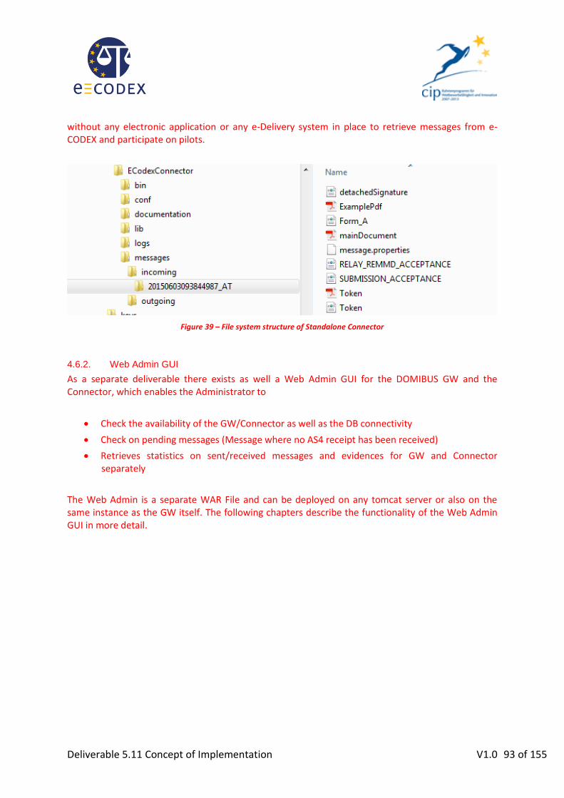
Deliverable 5.11 Concept of Implementation V1.0 93 of 155
without any electronic application or any e-Delivery system in place to retrieve messages from e-CODEX and participate on pilots.
Figure 39 – File system structure of Standalone Connector
4.6.2. Web Admin GUI
As a separate deliverable there exists as well a Web Admin GUI for the DOMIBUS GW and the Connector, which enables the Administrator to
Check the availability of the GW/Connector as well as the DB connectivity
Check on pending messages (Message where no AS4 receipt has been received)
Retrieves statistics on sent/received messages and evidences for GW and Connector separately
The Web Admin is a separate WAR File and can be deployed on any tomcat server or also on the same instance as the GW itself. The following chapters describe the functionality of the Web Admin GUI in more detail.

Deliverable 5.11 Concept of Implementation V1.0 94 of 155
4.6.2.1. Monitoring page
Figure 40 –Monitoring Page of Web Admin
This page gives an overview if:
The connector can be reached via JMX or REST.
A connection to the DB can be made.
All the timer jobs on the connector side are working
Any messages are pending on the GW (no AS4 receipt has been received)
In case the status is green everything is ok, yellow indicates a warning and red means there is an error (e.g. the connection to the DB could not be established)
4.6.2.2. Statistics pages
There are two different pages available.
Summary Page:
This page shows simple diagrams for overall data. At the actual state it shows the amount of incoming/outgoing messages and the type of service.

Deliverable 5.11 Concept of Implementation V1.0 95 of 155
Figure 41 –Statistics Overview Page of Web Admin
Custom Page:
Here, the messages can be filtered by different parameters. By using the “Generate” button, the result is displayed in the table below.
The loupe symbol in each row shows the evidence history.
Figure 42 –Custom Statistics Page of Web Admin
The table data can be exported in the formats: PDF, CSV and XML by clicking the appropriate icon under the table.
4.7. Configuration The configuration of the DOMIBUS GW as well as the connector is explained in the installation instructions of the GW and the connector. Both documents are bundled together with the software components and describe all the configuration fields in detail.

Deliverable 5.11 Concept of Implementation V1.0 96 of 155
5. e-Payment
5.1. Scope and definition There are some MS where, according to their national legal requirements, payment of court fees is mandatory to start a judicial process. Payment of court fees is closely related to each MS legal requirement and the type of payment evidences that are recognized and accepted by the destination court. From a legal point of view, not all the Member States need payment in their judicial context, in fact not all the regulations associated to e-CODEX pilots include payment as a requirement, e.g. Small Claims78. Even for future use cases the legal settings in most national countries should be observed, as they define and establish the solutions that are recognized as valid to execute payment.
WP5 focuses only on the payment of court fees and not on the transfer of money for penalties derived from the decisions for a proceeding79. National laws, rules and derived contracts with financial entities form a scenario that is not much flexible as to allow normalizing e-Payment among countries easily. Moreover, although banks play an important role in the payment process, involving banks in the solution would be too complex and should therefore be out of scope of the e-CODEX project. Furthermore, only a few countries require payment of court fees, so e-Payment must be an optional feature for cross-border filing. If a Member State does not require any payment of court fees it should not be forced to implement it.
Of course, the e-Payment solution defined by e-CODEX should be suitable for all the Member States, covering all their basic needs and restrictions. For use cases in which payment of court fees is required the user must be provided with the accurate information and the appropriate means to pay. As a central reference for the European citizens the e-Justice Portal is the best option to be considered as a suitable place to publish the details and instructions specified by each Member State. This website would provide users with references to the appropriate information about the payment process for the country in which he is filing the claim and links to the appropriate national e-Payment solution. These national solutions obviously take into account the national legal requirements for e-Payment.
Definitions on e-Payment80 settled by the Legal and Security Subgroup are:
The user should have the instructions about how to pay/ when to pay court fees. e-CODEX should provide access to the instructions/ user guidance regarding how the payment is to be made. This information is to be provided by the MS calling for the payment of court fees.
The translation of documents related to e-Payment is up to the countries, translation is possible but not necessary. The documents are in the language of the competent court because this is part of the judicial procedure81. The European Commission will be in charge of
78 See REGULATION (EC) No 861/2007 OF THE EUROPEAN PARLIAMENT AND OF THE COUNCIL of 11 July 2007 establishing a European Small Claims Procedure 79 agreed in the WP5 meeting held in Madrid on May 2011
80 settled in the meeting on key legal issues held in Düsseldorf on 30th September 2011
81 decision made in e-CODEX Management Board, 2-3 November 2011 – Berlin, Germany

Deliverable 5.11 Concept of Implementation V1.0 97 of 155
translating the information to the European official languages, so this allows each Member State to provide the information in its own language.
For the payment of court fees (when needed): the user is offered a link to the national e-Payment solution provided by the receiving MS82. There should also be an electronic receipt.
e-CODEX does not support the payment itself but the attachment of the payment evidence will be supported, according to receiving country’s rules.
For the use cases (i.e. Small Claims and EPO) where the form permits the user to include the bank information for the payment of fees, there should be a check box stating that the claimant accepts the fact that the court can request for the payment to be done using the claimant’s bank details.
At least it should be possible to send the e-Payment evidence as an attachment or the e-Payment id as a reference. If this is to be included in the form, WP6 have to consider if a place for the e-Payment id and evidence must be provided.
5.2. e-Payment overview
The functionalities to be offered to the users are:
information on when payment of court fees is required, how much should be paid and how to proceed;
a way to access the online e-Payment solutions for executing the payment and
means to handle the corresponding payment receipts.
The e-CODEX project aims to develop the interoperability building blocks for e-Justice services in Europe that address the horizontal issues between Member States. The e-Payment Building Block (e-Payment BB), which could be subdivided into smaller subBBs, has been identified in D5.2. The e-Payment BB will implement the use case relevant for e-CODEX WP5 handling court fees, which have to be paid before a proceeding can be initiated. It has to be mentioned that there is another use case, which handles the payment of penalties between the claimant and the opponent. It has been agreed that this use case is out of scope of e-CODEX and WP5.
e-Payment BB includes the handling and sending of e-Payment receipts together with the message as an additional business document proving a successful payment of the respective court fees. Due to the fact that this payment receipt is an additional business document and that the destination court will only accept recognized receipts, it must be delivered on a 1:1 basis as received from the payment service. The receipt can be an attachment (pdf, xml) or a code (pre-payment).
The online payment itself via direct bank or credit card interfaces is out of scope for WP5. The reason for that is that normally, in every country, well defined and widely used electronic payment applications are already in place, which should be used further on. The European e-Justice Portal here only invites the citizen to initiate the payment by calling the correct national e-Payment interface where to obtain the appropriate receipt for the successful/unsuccessful payment.
82 See statement in D5.2, at the end of § 7.1

Deliverable 5.11 Concept of Implementation V1.0 98 of 155
In case of online pre-payment of court fees, there is a need for cross-referencing the case data to be submitted with the payment:
The case data, which is to be submitted to the court, has to include the corresponding evidence to prove the successful payment of the correct amount of court fees in the way accepted by the court.
o The payment data must include a reference to the (preliminary) case or document number to be used by the national accounting system for transferring the payment to the right court (e.g.: some countries use a unique document number, pre-printed on forms to be filled and submitted. You have to specify this document number on your payment of court fees, so the court can check, if the payment of court fees was received, before proceeding with the case).
Table below lists those MS where payment is mandatory to start a judicial process including some others and their situation.
Country Mandatory Solution available
AT YES YES
DE YES YES
ES NO Unnecessary
FR YES YES
IT YES YES
NL TBD Pilot
PT YES Order for payment procedure
Table 10: Inputs on Payment from the MS

Deliverable 5.11 Concept of Implementation V1.0 99 of 155
5.3. e-Payment Business process
The steps that explain e-Payment are shown in the following picture:
Figure 43 – e-Payment business process
1. The user asks to initiate a proceeding by accessing the appropriate form to be filled, either in its National Service Provider or in the e-Justice Portal.
2. The user is advised either by the National Service Provider or by the European e-Justice Portal that payment is required for that destination. Information provided by the MS about the payment of court fees is collected in the European e-Justice portal where the user is informed how to do the payment.
3. The user accesses the appropriate e-Payment solution and proceeds with the payment.
4. The user obtains the payment receipt.
5. The user fills the form and attaches the payment receipt.
6. The e-CODEX gateway identifies the receiving MS. When payment is required, it is up to the sending country to check by its National Service Provider, that the appropriate receipt is attached before passing message to the e-CODEX Gateway.
7. The sending e-CODEX gateway sends the “e-CODEX message” through “e-CODEX infrastructure” to the receiving e-CODEX gateway of the addressed MS.
8. The message is delivered to the e-CODEX gateway of the receiving MS. When payment is required, it is up to the receiving country to check, in its National Service Provider, that the payment receipt is attached and is valid.
9. Finally the receiving National Service Provider forwards the message to the addressed user.

Deliverable 5.11 Concept of Implementation V1.0 100 of 155
10. Receiver should be able to check the receipt with his respective national e-Payment solution (this is up to the MS’s rules).
In this scenario it is therefore necessary to provide an access point to the information about payment of court fees, mainly for citizens. Most countries only provide national solutions for legal professionals and judicial authorities, but not for citizens. Therefore, the e-Justice Portal seems to be the best option to include information to the citizens about judicial procedures, and to offer forms (e.g. Small Claims and EPO) for initiating some of them. Currently, the e-Justice Portal, in its “Going to court” section there are pages called “Court fees concerning European Payment Order procedure”
83
and “Court fees concerning Small Claims procedure”84 where information about cost of proceedings is provided.
5.4. e-Payment specifications
The solution proposed by e-CODEX follows the principle of reuse rather than reinventing the wheel by involving:
- The e-Justice Portal, as the main access for citizens to electronic justice and, in particular, to the information about payment of court fees;
- The National e-Payment systems, where to execute the appropriate payment of fees;
- The e-CODEX infrastructure to handle the payment evidence together with the case file.
83 https://e-justice.europa.eu/content_court_fees_concerning_european_payment_order_procedure-305-en.do
84 https://e-justice.europa.eu/content_court_fees_concerning_small_claims_procedure-306-en.do

Deliverable 5.11 Concept of Implementation V1.0 101 of 155
Figure 44 – e-payment scenarios
#BB Code: BBP001 BB Title: e-Payment information access
BB description:
As the users will need to be aware of the basic aspects: regulation setting the court fees, which processes require payment of fees, the amount to be paid and the rules to calculate it, when should they be paid, what are the court requirements about evidences of payment, etc., this BB includes the necessary functionalities to access to e-Payment information already existing in order to know perfectly how, where, how much should be paid on a judicial procedure.
Two scenarios are possible:
- Citizens accessing to this information directly through the e-Justice Portal (reusable existing BB).This is the scenario to be developed for e-CODEX.
- Judicial Professionals could have e-Payment information available at their own solutions offered by their service provider (these solutions could connect directly

Deliverable 5.11 Concept of Implementation V1.0 102 of 155
to e-Justice Portal). Developing this scenario is up to the national service providers.
NOTE: Providing this information in the languages of the European Union is up to the countries, translation is possible but not necessary.
Other BB dependences:
e-Justice Portal
Transportation
Directory
Administration
REQ Traceability:
WP5-RQ-F-004 national e-Payment solution redirection.
WP5-RQ-F-005 Interoperability with e-Justice portal
Info
rmat
ion
D
ata
Inputs:
Addressee MS
Outputs:
Detailed information about e-Payment process, depending on each Member State requirements. (based on the information provided by each MS)
BB
Tec
hn
ical
De
scri
pti
on
Fu
nct
ion
alit
y
Table 11: e-Payment Information
#BB Code: BBP002 BB Title: e-Payment execution
BB description:
This BB provides access to the appropriate e-Payment solution by redirecting to the corresponding national e-Payment service provider where the user is able to pay and obtain the payment receipt.
Other BB dependences:
National e-Payment Solutions
REQ Traceability:
WP5-RQ-F-004 national e-Payment solution redirection.
WP5-RQ-F-005 Interoperability with e-Justice portal
Info
rmat
ion
D
ata
Inputs:
- Addressee MS,
- data required for the payment execution (applicant id, case id, court, amount of money to be paid …),

Deliverable 5.11 Concept of Implementation V1.0 103 of 155
Outputs:
- Valid e-Payment evidence. Receipt from the national e-Payment service provider complying with the requirements to be valid in front of the court according to the rules of the receiving country.
BB
Tec
hn
ical
De
scri
pti
on
Fu
nct
ion
alit
y
Table 12: e-Payment execution
#BB Code: BBP003 BB Title: e-Payment evidence handling
BB description:
This BB includes the handling and sending of the payment evidence (receipt) together with the message as an additional business document proving a successful payment of court fees.
This piece of evidence (the receipt of the transaction) will be transported as any other data or document attached to the appropriate process form.
Other BB dependences:
National e-Payment Solutions
Transportation
Directory
Administration
REQ Traceability:
WP5-RQ-F-004 national e-Payment solution redirection.
WP5-RQ-F-005 Interoperability with e-Justice portal
Info
rmat
ion
D
ata
Inputs:
Required payment information: Proceeding, case id, value of the claim, court/MS responsible for.
Valid e-Payment evidence from the appropriate national e-Payment service provider with the information required according to the receiving MS legal regulations.
Outputs:
Message containing the payment evidence attached to the appropriate form or document to be sent to the appropriate destination.

Deliverable 5.11 Concept of Implementation V1.0 104 of 155
BB
Tec
hn
ical
De
scri
pti
on
Fu
nct
ion
alit
y
Table 13: e-Payment receipt handling
5.4.1. National e-Payment parameters
The e-Payment parameters to be provided by the Member States participating in the e-CODEX pilots are included in following table:
- e-Payment user information: The information to be offered to the users should be enough for the user to be aware of the basic points: regulation setting the court fees, which processes require payment of fees, the amount to be paid and the rules to calculate it, when should they be paid, what are the court requirements about evidences of payment, etc. This information will be provided by the piloting countries using a template that has been defined in order to ease with the provision of their information on payment of court fees.
- e-Payment solution: the reference to be used by a citizen to access to the e-Payment application (electronic address, URL, applet). It is advisable to provide citizen with guidance on the access and use of the national e-Payment solution, i.e. a user manual.
- Means of payment: means like credit card, bank transfer, direct debit, voucher, cash, etc. - Moment of payment: pre-paid, pay-now, pay-later, etc. - Type of Receipt: electronic stamp, bar code, pdf receipt, XML, URL, etc.
Payment of court fees templates
Information listed above is to be included in the e-Justice portal for the user to have a clear view of the procedure and national details before proceeding with the payment of the required court fees. For this purpose, two templates, one for EPO and another one for Small Claims, have being defined together with the Directorate General for Justice (DGJUST) of the European Commission ensuring that MS will provide the information in a homogeneous way.
All e-CODEX participants must fill these templates providing their information about:
payment of court fees is to be included (even if they do not have court fees; if this is the case it would be enough for them to indicate it at the start of the template)
electronic payment of court fees must be included by those participants providing this option
These templates are included as an Appendix IV – e-Justice portal templates for payment information from MS in this document.

Deliverable 5.11 Concept of Implementation V1.0 105 of 155
5.5. e-Payment Considerations
5.5.1. Standards
This BB will be aligned to standards and guidelines established from WP7 for e-CODEX.
The information associated to a payment service provider transfer would be considered as any other kind of information and included in the message to be sent to court. XML is the standard being considered for the e-CODEX messages.
5.5.2. Security
The same level and security requirements for e-Payment information as for any other kind of judicial data/information would be taken into account. Payment guarantees are those given by the payment process, e-CODEX will only guarantee the correct and secure handling of payment evidences.
5.5.3. Inputs on e-Payment from MS
Those Member States where e-Payment is mandatory made available significant information about their national e-Payment approach. It has been considered worthy to include this information as Appendix V – Information about e-Payment from MS.

Deliverable 5.11 Concept of Implementation V1.0 106 of 155
6. Directory of judicial atlas
6.1. Introduction One of the main requirements for communication is having a sending and a receiving party. The retrieval of the receiving party and its contact details is a challenge in itself. In many cases the sender might not even know whom to address in a certain proceeding. If that is not known, how would this person be able to use the correct parameters for addressing?
As an initiator of a proceeding you will have to have quite extensive knowledge of the proceeding, in order to be able to find your addressee. For each proceeding you might have to turn to a different court or judicial authority. Additionally, each Member State applies different business rules in determining what authority is handling the procedure. It is these business rules that have to be specified.
In chapter 6.3 the actual status is described for how to resolve the competent courts in the different piloting areas. There exists also an additional scenario; in e-CODEX we called it “Plan B” which is to request competent authority information in the relevant Member State. This scenario is described in paragraph 6.4.
In electronic messaging the address of the electronic business document differs from the geographical address of the processing employee. Section 6.2 explains these differences.
6.2. Electronic vs. traditional addressing In the comparison between traditional postal delivery and the electronic delivery both similarities and differences are found.
The most important difference is that all the addressing information for an end-to-end delivery must be known before sending a physical letter. Traditional postal service does not add any intelligence along the line. Postal services cannot interpret the envelope and certainly cannot route on (part of) the information which resides inside the envelope. In electronic messaging interpreting envelope information is possible and if chosen, content based routing is an option. Content based in this context is meant as content of a business document header (SBDH). The e-CODEX infrastructure is not to open/read contents of the exchange of business process itself.
A distinction must be made between old fashioned postal delivery on obtaining the address and putting this information on the envelope. Country, city, street and number are put on the envelope to enable the postman to deliver mail at the correct door. Behind that door, the employee who processes the mail is located. In order to send the letter to that specific employee, the address of his or her organisation must be put on the envelope. If this address is unknown one can do a look up in the yellow pages, phonebook or zip code book. Or if a telephone number is known, the sender can obtain the address information by making a call to the addressee. Once the correct address is obtained, it can be put on the envelope and handed over to the mailman (resembling scenarios 3 & 4).
An acknowledgement of receipt contains information on the receiving party of the initial message. This information is needed from a legal point of view. What you see here is that this information will come to you even if you didn’t know exactly where you have sent the message in the first place. Normally the acknowledgement of receipt will return to the sender of the initial message containing

Deliverable 5.11 Concept of Implementation V1.0 107 of 155
the business information in a matter of seconds. If, at that moment the addressee information is stored in the information system of the sender of the initial business document, this organisation has all the legally needed information. This will be the acknowledgement of receipt provided by the infrastructure. A business acknowledgement stating that the request was accepted/denied by some clerk will be returned after processing the request. Depending on the electronic address the user provided in the form for ‘return traffic’ it will be returned to the e-Justice portal, or to a nationally implemented secure electronic address of the user.
6.2.1. An example
An application for EPO is processed by a court situated in Rome. So the processing department must be addressed in the business document and is, from a legal point of view, essential. From a technical point of view, the addressing could be of a very different nature.
Let’s assume that all courts in Italy use a nation-wide system which is administered by a service provider in Milan. In that case, the “electronic address” would be that of the service provider in Milan expressed in a URL, organisation code, etc.., but not as Street+number+postalcode+city and certainly not the geographical of electronic address of a specific court.
The system adds the content of the business document into the (national) case management system. Within this system it is added to the workflow of the employee or department of a specific court in Italy which processes the application.
In this particular example, it is likely that a judge of the processing court in Rome is not interested at all in the fact that the electronic message was picked at the Italian border by a Gateway, from there delivered to a national service provider which hosts the Italian case management system and has allocated the contents of the message to the court of Rome.
The point is that the electronic address is of no value from a legal point of view regarding the business process. Likewise, the geographical (traditional mail) address is of no use for electronic delivery to the ultimate addressee. Address information that is needed from a business perspective resides inside the business documents or its attachments, the actual message. The electronic address resides in the message envelope or the message header.
In order to know how to address a specific court (or courts in general) by electronic means, the e-Justice portal must provide the electronic address to put in the message header or on the message envelope for delivering purposes, as well as the geographical address to put inside the business document (xsd and/or pdf) for legal purposes.
The functionality must be provided by the European e-Justice portal itself via the European Court Database. Alternatively the electronic address can be determined statically if there is only one court competent or as an alternative scenario (described in more detail in chapter 6.4) with a Web Service/business transaction initiated from the European e-Justice portal is that:
A user enters the requested parameters for the retrieval of a competent authority
A request is initiated by the e-Justice portal to the relevant Member State, providing the entered parameters
The Member States respond with both the geographical and the electronic address. Preferably also information on court fees, payment methods, etc… is provided in this response
The e-Justice portal puts the geographic address in the (web)form(s) of the application and temporarily stores the electronic address awaiting the sending of the form by the user. The user needn’t sign for the electronic address for it is not part of the legal procedure or used
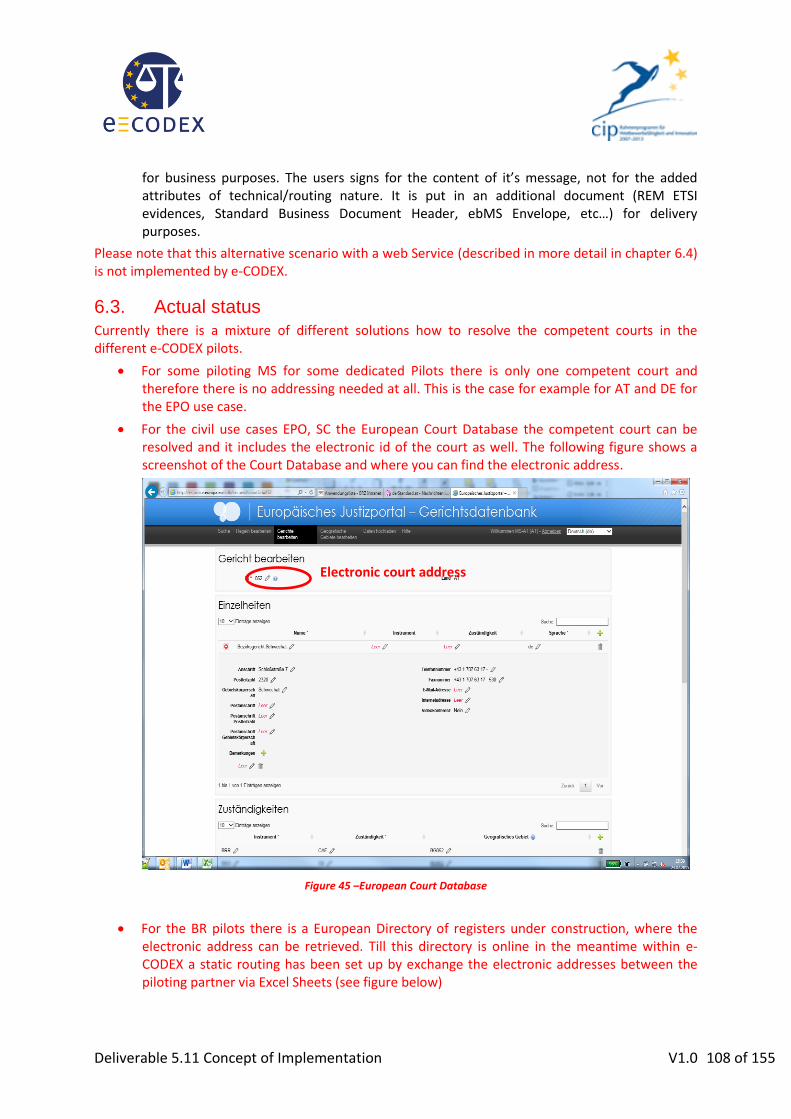
Deliverable 5.11 Concept of Implementation V1.0 108 of 155
for business purposes. The users signs for the content of it’s message, not for the added attributes of technical/routing nature. It is put in an additional document (REM ETSI evidences, Standard Business Document Header, ebMS Envelope, etc…) for delivery purposes.
Please note that this alternative scenario with a web Service (described in more detail in chapter 6.4) is not implemented by e-CODEX.
6.3. Actual status
Currently there is a mixture of different solutions how to resolve the competent courts in the different e-CODEX pilots.
For some piloting MS for some dedicated Pilots there is only one competent court and therefore there is no addressing needed at all. This is the case for example for AT and DE for the EPO use case.
For the civil use cases EPO, SC the European Court Database the competent court can be resolved and it includes the electronic id of the court as well. The following figure shows a screenshot of the Court Database and where you can find the electronic address.
Figure 45 –European Court Database
For the BR pilots there is a European Directory of registers under construction, where the electronic address can be retrieved. Till this directory is online in the meantime within e-CODEX a static routing has been set up by exchange the electronic addresses between the piloting partner via Excel Sheets (see figure below)
Electronic court address

Deliverable 5.11 Concept of Implementation V1.0 109 of 155
AT HG Wien 007 HG Wien
AT LG Korneuburg 119 LG Korneuburg
AT LG Krems 129 LG Krems
AT LG St. Pölten 199 LG St. Pölten
AT LG Wiener Neustadt 239 LG Wiener Neustadt
AT LG Eisenstadt 309 LG Eisenstadt
AT LG Linz 458 LG Linz
AT LG Ried im Innkreis 469 LG Ried im Innkreis
AT LG Steyr 499 LG Steyr
AT LG Wels 519 LG Wels
AT LG Salzburg 569 LG Salzburg
AT LG Leoben 609 LG Leoben
AT LG für ZRS Graz 638 LG für ZRS Graz
AT LG Klagenfurt 729 LG Klagenfurt
AT LG Innsbruck 818 LG Innsbruck
AT LG Feldkirch 929 LG Feldkirch Figure 46 –Excel Sheet listing business register courts
For the criminal use cases like MLA or FD in long term the integration into the European Court Database will be the preferred solution. In short term a static routing as for the BR can be evaluated as well.
6.4. Possible alternative scenario
A scenario described here for finding ultimate addressees is a request to a Member State. Based on certain parameters the Member State (not necessarily the national Gateway) responds to this request by providing details on the requested competent authority.
By smartly creating a generic Business Transaction or Web Service all currently chosen use cases will be supported. Future developments can easily be incorporated in this transaction. The current use cases require only the retrieval of courts, but in future other (judicial) authorities can be found accordingly. (E.g. police departments, district attorneys, official agencies, etc.)
This proposal does require some effort from each of the Member States. They will somehow have to create a repository of authorities and their fields of competence/jurisdiction. This is an exercise Member States will have to perform anyway, because the e-Justice portal requires this kind of information too. The Web Service or ebMS transaction will address this repository.
In future developments of the e-Justice portal itself, it might use this transaction to dynamically show competent authorities on their website. Deploying this service on the portal will reduce maintenance of this information. The task of keeping the information up-to-date lies in the hands of the respective Member States. The e-Justice portal will be in the role of the “requestor” and the national responding repository as “provider” (see Figure 47 – Address resolution business transaction). In proceedings in the field of criminal law where two or more authorities communicate without using the e-Justice portal, the requesting authority can initiate the business transaction in the role of “requestor”.
By creating such a business transaction and designing it in a generic approach and making it “role based” it will be deployable by the e-Justice portal and national authorities. In future it might even be deployed by notaries, lawyers and other entities, providing they have access to an e-CODEX Gateway.
Electronic court address
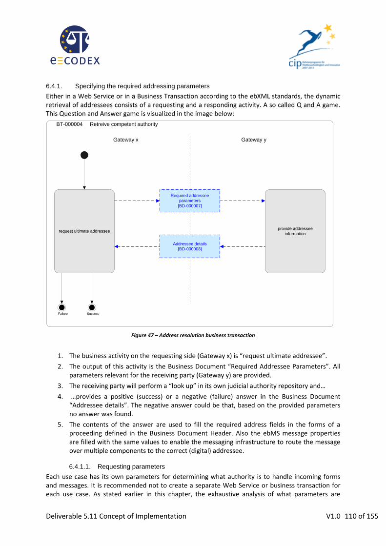
Deliverable 5.11 Concept of Implementation V1.0 110 of 155
6.4.1. Specifying the required addressing parameters
Either in a Web Service or in a Business Transaction according to the ebXML standards, the dynamic retrieval of addressees consists of a requesting and a responding activity. A so called Q and A game. This Question and Answer game is visualized in the image below:
BT-000004 Retreive competent authority
request ultimate addressee
Required addressee
parameters
[BD-000007]
provide addressee
information
[BD-]
Addressee details
[BD-000008]
SuccessBedrijfs-falen
Failure
[BD-][BD-]
Gateway yGateway x
Figure 47 – Address resolution business transaction
1. The business activity on the requesting side (Gateway x) is “request ultimate addressee”.
2. The output of this activity is the Business Document “Required Addressee Parameters”. All parameters relevant for the receiving party (Gateway y) are provided.
3. The receiving party will perform a “look up” in its own judicial authority repository and…
4. …provides a positive (success) or a negative (failure) answer in the Business Document “Addressee details”. The negative answer could be that, based on the provided parameters no answer was found.
5. The contents of the answer are used to fill the required address fields in the forms of a proceeding defined in the Business Document Header. Also the ebMS message properties are filled with the same values to enable the messaging infrastructure to route the message over multiple components to the correct (digital) addressee.
6.4.1.1. Requesting parameters
Each use case has its own parameters for determining what authority is to handle incoming forms and messages. It is recommended not to create a separate Web Service or business transaction for each use case. As stated earlier in this chapter, the exhaustive analysis of what parameters are

Deliverable 5.11 Concept of Implementation V1.0 111 of 155
required is perhaps to be performed by the analysts of WP3. Nevertheless a quick look at the use cases EPO (UC1), Small Claims (UC2) and EAW (UC3) provides the short list below:
Parameter Description
Use Case
1 2 3 4 5
Procedure Not every court is competent to process any procedure. Based on EU procedure a MS can distinguish Criminal / Civil law, what types of court are competent.
(example: EPO, Small Claim, EAW, Financial Penalties, etc..)
√ √ √
Field of law In Belgium for instance a claim (EPO) regarding an issue on labour will be processed in a specific court
√ √
Amount of claim If the amount of a claim exceeds a certain national limit, another court might be the competent one
√ √
Location of defendant Some MS determine the competent court based on the residence of the defendant
√ √ √
Table 14: Judicial atlas Web Service input parameter
6.4.1.2. Responding parameters
Parameter Description
Use Case
1 2 3 4 5
Procedure Responding to the procedure √ √ √
Competent authority Name of the competent authority(s). The response might contain multiple competent authorities from which a requestor can choose
√ √ √
Geographical address To be filled in the forms √ √
Electronic address For electronic routing to correct addressee (see 6.2.1)
√ √ √
Court fees applied Information on applied court fees, the amount and payment methods
√ √
Accepted languages Applications must be filed in a language, the receiving MS accepts. It is helpful to the user if this information is provided automatically.
√ √ √
Table 15: Judicial atlas Web Service output parameter

Deliverable 5.11 Concept of Implementation V1.0 112 of 155
7. Specifications validation tests
Specifications written in present document should be tested and validated. Basic tests have been described at the time of writing the specification. These tests are explained below to confirm that the specification can be implemented. Detailed tests for each functionality of the pilots are being described in e-CODEX and more involved interoperability and/or conformance tests are still under discussion.
7.1. European e-Delivery Transport Infrastructure Validation of the transport infrastructure and the Gateways (GW) and Connectors are done together, the relevant tests are described together in the next section.
7.2. Gateway
7.2.1. Test environment
MySQL
MySQL
ebMS 3.0Https
File IO
jdbc
Jdbc
Local keystore
Local keystore
GW1 (TOMCAT) GW2 (TOMCAT)
Self Signed Certificates
Self Signed Certificates
In - Out
In -out
Figure 48 – Gateway test environment
The test environment consists of the 2 GWs and Connectors up and running communicating with each other. Each of them is hosted on a different HW and has an own DB instance. For test purposes self-signed test certificates are used for the network level as well as the ebMS internal level for signing and encrypting the message. For test purpose the national subsystems are simulated.

Deliverable 5.11 Concept of Implementation V1.0 113 of 155
7.2.2. Test scenarios
The overall test scenarios for the pilots are described in the D10.2 document and are the basic input for the scenarios tests specifically for the GW and Connector. The detailed specification of the test scenarios you can find in the Deliverable D5.585. So the following description is just a short summary.
7.2.2.1. Sending a message from A to B
After the successful setup of the test environment a message is sent from one Connector to the other. This is done by calling a Web Service of the GW.
Please note: For tests at this stage test files with dummy data will be used. Only in the final end to end tests representing the scenarios in D10.2 according to the Pilot Uses real EPO, Small Claims or EAW test data (forms) will be used.
Includes the following checks
Checking the SSL connection Checking the correct encryption of the message Checking the created Trust OK token Checking if the attachment is included correctly Checking if the end user identification is complete in the ebMS3 message properties as
well as in the SBDH header. Checking the log entry Checking the report entry Checking if a proper evidence is sent back to the sending Connector indicating successful
or unsuccessful delivery.
Performing negative tests:
Shutdown the national subsystem (file system not available, Web Service not available) and check if the corresponding evidence is sent and the right status has been set in the DB
Shutdown temporary the partner Gateway and check if the message has been resent if the GW is up and running again according to the configured policy.
Shutdown the partner GW and check if the corresponding evidence is sent and the right status has been set in the DB
The test of sending process has been divided into 6 steps of detailed analysis: Step 1 Sending Message from National System (or Simulator) A to Connector A Step 2 Forwarding Message to GW A Step 3 Forwarding Message to GW B Step 4 Forwarding Message to Connector B Step 5 Forwarding Message to National System (or Simulator) B Step 6 Receiving Message at end-user / application Test pre-conditions: In terms of preparatory conditions the Connector and Gateway have to be operational in both systems – the sending country A and the receiving country B. Test documents have to be prepared and created in PDF and XML formats. For the endpoints the A and B National Systems or Simulators
85 Deliverable D5.5 “Description of tested functions and outcome” https://www.jol.nrw.de/bscw/bscw.cgi/3984696

Deliverable 5.11 Concept of Implementation V1.0 114 of 155
have to be operational and in both Gateways the P-Modes have to be configured properly. Security measures have to be preserved by installing proper certificates. Test post-conditions:
After the test execution, the test document will be available at the National System in country B (or National Simulator) with correct messages. All the evidences of proper communication will be sent and received and the logging entries will remain in the DB. Message content will be available at the endpoint of the communication only.
Step 1 Sending Message from National System (or Simulator) A to Connector A The first step encompasses the process of sending a message from a National System (or a Simulator) from country A to the Connector A. As a result a proper log entry is available at the connector. Within this step two error scenarios may occur: Connector A is not available or Connector A cannot process the Message/Document. Step 2 Forwarding Message to GW A In the second step of the process the Connector A proceeds with the message to the Gateway in country A. As a result proper log entries occur both in the Connector A and in the Gateway A. Furthermore a submission acceptance evidence is received at National System A.
In the event of an error scenario that Gateway A is not available an evidence submission rejection is received at National System and a log entry is created in the connector.
Step 3 Forwarding Message to GW B In the next step the Gateway A forwards the message to Gateway B. In the result of that action log entries are created in both Gateways. In the event of an error that Gateway B is not available a log entry in the Connector and Gateways is created and an evidence of Relay_REMMD_Rejection is received at the National System. Step 4 Forwarding Message to Connector B The following step is the process of forwarding the Message to the Connector B in the result of which log entries are created in the Connector B and Gateway B. Relay MD evidence is received at Gateway/Connector/National System A. In this step of the testing two error scenarios are envisaged. Connector B is not available and as a result a proper log entry is created in the Gateways as well as in Connector A and a Relay_REMMD_Rejection evidence is received at National System A. In the second error scenario in which Connector B is not able to process the Message and Document defined log entries are created in the Connector of A and B and evidence of NonDelivery is received at National System A. Step 5 Forwarding Message to National System (or Simulator) B The fifth step of the testing process is the Message forwarding to the National System B (from the Connector B). As a result log entry is created in the Connector and Delivery Evidence is received at Gateway / Connector / National System in country A. If the National System B is not available as an error, a log entry is created in the Connector B and evidence of NonDelivery is received at National System A. If delivery Confirmation is not received similarly a log entry is created in the Connector B and evidence of NonDelivery is received at National System A

Deliverable 5.11 Concept of Implementation V1.0 115 of 155
Step 6 Receiving Message at end-user application In the sixth step of the testing process the Message is received at the end-user application. In the result of this step a log entry is created in the Connector B, Retrieval Evidence is received at the levels of Gateway / Connector / National System in country A and no message content is available at Gateway and Connector A or B. If Message retrieval evidence is not received a corresponding log entry is created in the Connector B and the evidence of NonRetrieval is received at National System A.
7.2.2.2. Sending a message from B to A
This test scenario is the same as the above one, but in the other direction.
7.2.2.3. Gateway – to – Gateway Testing
The testing of communication between Gateways is mainly a technical task. For the process of communication to be uninterrupted proper configuration of the environment is required especially the firewall systems have to be set to accept incoming connections and to allow outgoing connections. Also the connectivity of the HTTPS protocol needs to be configured properly.
7.3. e-Payment
This functionality is under the control of the e-Justice Portal. The Portal provides the static information about the e-Payment required by the MS and it also provides the links to the national payment systems. Because it is under the control of the e-Justice Portal also the test responsibility is under the control of the e-Justice Portal. Therefore the following chapter gives just a high level overview about possible test scenarios:
e-Payment information access
e-Payment execution
e-Payment receipt handling
7.3.1. e-Payment information access
This functionality should offer the user information on when a payment is required and what and how much should be paid. This information is provided by the MSs as listed in section 5.4.1.
Checking will consist just in accessing the information and verify the user is able to: (1) know whether e-Payment is required; (2) how much should be paid; (3) and how to proceed.
7.3.2. e-Payment execution
The user will be linked to the respective national solution in the appropriate Member State. The way to access the online payment solutions for executing the payment is provided by the MSs as listed in section 5.4.1.
Checking will be as simple as accessing the national solutions as indicated by the MSs.

Deliverable 5.11 Concept of Implementation V1.0 116 of 155
7.3.3. e-Payment evidence delivery
Each solution produces a different type of evidences as listed in section 5.4.1, even there are some cases in which evidence is not needed. The means to handle the corresponding payment receipts or evidences would be just attaching the document or information to the message.
For this test, MS are asked to provide a sample of the evidence given by their solutions.
Checking will be performed just by verifying that the sample evidences provided by the MSs can be delivered together with the message.
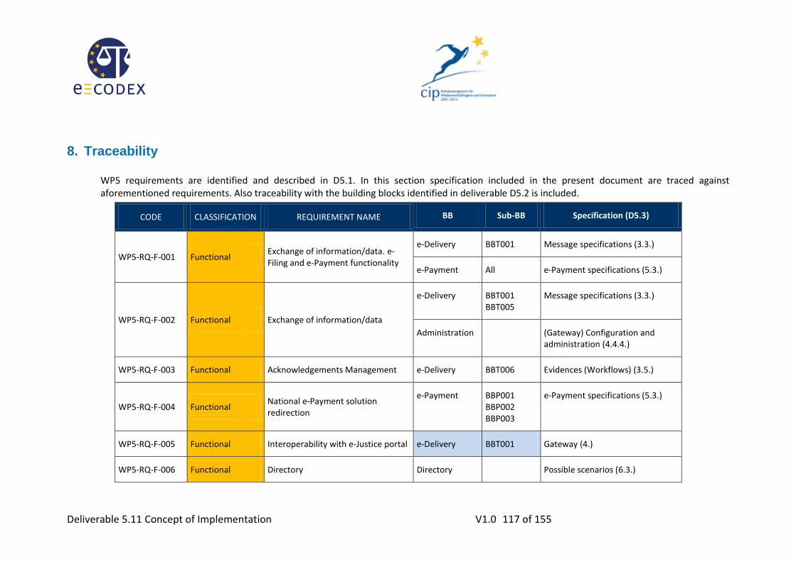
Deliverable 5.11 Concept of Implementation V1.0 117 of 155
8. Traceability
WP5 requirements are identified and described in D5.1. In this section specification included in the present document are traced against aforementioned requirements. Also traceability with the building blocks identified in deliverable D5.2 is included.
CODE CLASSIFICATION REQUIREMENT NAME BB Sub-BB Specification (D5.3)
WP5-RQ-F-001 Functional Exchange of information/data. e-Filing and e-Payment functionality
e-Delivery BBT001 Message specifications (3.3.)
e-Payment All e-Payment specifications (5.3.)
WP5-RQ-F-002 Functional Exchange of information/data
e-Delivery
BBT001 BBT005
Message specifications (3.3.)
Administration (Gateway) Configuration and administration (4.4.4.)
WP5-RQ-F-003 Functional Acknowledgements Management e-Delivery BBT006 Evidences (Workflows) (3.5.)
WP5-RQ-F-004 Functional National e-Payment solution redirection
e-Payment
BBP001 BBP002 BBP003
e-Payment specifications (5.3.)
WP5-RQ-F-005 Functional Interoperability with e-Justice portal e-Delivery BBT001 Gateway (4.)
WP5-RQ-F-006 Functional Directory Directory Possible scenarios (6.3.)

Deliverable 5.11 Concept of Implementation V1.0 118 of 155
CODE CLASSIFICATION REQUIREMENT NAME BB Sub-BB Specification (D5.3)
e-Delivery BBT003 Discovery, addressing and endpoint capabilities (3.4.)
WP5-RQ-F-007 Functional Access Management. Technical Identification and Authorization.
e-Delivery BBT004 (Gateway) 4.1.3. National TSL or authentication and authorization systems (IDM) (4.1.3.)
WP5-RQ-F-008 Functional National interface and EU Interface e-Delivery
BBT001 BBT007
(Gateway) Backend Integration - National System (4.1.2.2.)
WP5-RQ-F-009 Functional Format Validation e-Delivery BBT007 (Gateway) Plugin (4.3.2.4.)
(Gateway) Content mapping (4.4.3.)
WP5-RQ-F-010 Functional Standards conversion e-Delivery BBT007 (Gateway) Plugin (4.3.2.4.)
(Gateway) Content mapping (4.4.3.)
WP5-RQ-F-011 Functional Communication information Administration WP5_BBAdm
inistration (Gateway) Logging (4.3.2.3.)
WP5-RQ-F-012 Functional Statistics information Administration WP5_BBAdm
inistration (Gateway) Logging (4.3.2.3.)
WP5-RQ-NF-001 Non Functional European frameworks initiatives” requirements
ALL ALL ALL

Deliverable 5.11 Concept of Implementation V1.0 119 of 155
CODE CLASSIFICATION REQUIREMENT NAME BB Sub-BB Specification (D5.3)
WP5-RQ-NF-002 Non Functional e-CODEX - Standards and guidelines ALL ALL ALL
WP5-RQ-NF-003 Non Functional Mutual recognition in e-CODEX context. Circle of trust.
e-Delivery BBT004 (Gateway) National TSL or authentication and authorization systems (IDM) (4.1.3.)
WP5-RQ-NF-004 Non Functional Secure information exchange
e-Delivery BBT008 (Gateway) National TSL or authentication and authorization systems (IDM) (4.1.3.) (Gateway) Security (4.3.1.2.) End2End Encryption (3.6)
WP5-RQ-NF-005 Non Functional National Gateway’s Identification and authentication
e-Delivery
BBT002 BBT003
Discovery, addressing and endpoint capabilities (3.4)
(Gateway) Gateway Authentication (3.3.3.4.1.)
WP5-RQ-NF-006 Non Functional Integrity e-Delivery BBT002 (Gateway) National TSL or
authentication and authorization systems (IDM) (4.1.3.)
WP5-RQ-NF-007 Non Functional Electronic signatures e-Delivery BBT002 (Gateway) National TSL or
authentication and authorization systems (IDM) (4.1.3.)
WP5-RQ-NF-008 Non Functional Time stamping e-Delivery BBT009 Evidences (Workflows) (3.5)

Deliverable 5.11 Concept of Implementation V1.0 120 of 155
CODE CLASSIFICATION REQUIREMENT NAME BB Sub-BB Specification (D5.3)
FigureWP5-RQ-NF-009
Non Functional Information preservation. Personal Data Protection
e-Delivery
Administration
BBT008 4.3.2.3. Logging (4.3.2.3.) (Logging section)
WP5-RQ-NF-010 Non Functional e-CODEX Infrastructure administration
Administration (Gateway) Configuration and administration (4.3)
WP5-RQ-NF-011 Non Functional Administration Restricted Access (No unauthorised access)
Administration (Gateway) Configuration and administration (4.4.4.)
WP5-RQ-NF-012 Non Functional Architecture design ALL ALL ALL
WP5-RQ-NF-013 Non Functional Performance features ALL ALL ALL
WP5-RQ-NF-014 Non Functional Interoperable Platform ALL ALL ALL
WP5-RQ-NF-015 Non Functional Error Management e-Delivery BBT005
BBT006 (Gateway) Reliability (4.4.4.3.)
WP5-RQ-NF-016 Non Functional Availability ALL ALL (Gateway) HW Setup (4.1.1)
WP5-RQ-NF-017 Non Functional National Gateway’s requirements e-Delivery
Administration
ALL Gateway (4.)
Table 16: Traceability between requirements and specifications

Deliverable 5.11 Concept of Implementation V1.0 121 of 155
9. Conclusions
During the definition of the convergent e-Delivery solution described in chapter 3 the following conditions for the e-CODEX pilots have been defined.
For the e-CODEX pilots starting at the beginning of 2013 no dynamic routing/discovery will be implemented. The Gateway connections are statically defined in the p-mode definitions. There is only a prototype implementation of Dynamic Discovery available for future LSP project like e-SENS.
There will be no central hub in the middle.
SAML tokens are foreseen but out of scope and not used for the e-CODEX.
End User Identities will be transported in separate property fields of the message header.
By specifying the generic e-CODEX Gateway in the chapter 3 the following split between the national adapters and the generic Gateway has been defined:
Trust Ok Token document will be generated within the national adapters by tools provided by WP4. The trust ok token is just another document attached to the message.
The content conversion from the e-CODEX XML Schemas to the national existing ones will be done in the national adapters.
The cross border reliable and secure messaging will be provided by the Gateway by AS4 profile
The Gateway will include a logging, monitoring and configuration facility.
The Gateway will support the ETSI REM Evidences defined in chapter 3.4
After finishing the D5.3 the development for the generic Gateway started by establishing a developer team from volunteering MS and a common development environment. Additionally a workshop with the piloting MS took place (organized by WP3) to clarify the functionality needed by the national adapters.
After releasing the final version of the GW 3.0 the update document D5.11 is published in order to reflect the latest state of development.
Regarding e-Payment, national payment rules and legislation vary from one country to another and is not mandatory in all the European countries. The ground required to consider the option of building a common e-Payment solution should be having a homogeneous payment scenario in the Member States. The first step should be done in the legal interoperability layer before a CIP project would be able to define a European solution.
The e-Payment solution defined in the present document aims to provide citizens and other users with the appropriate means to be able to pay court fees in those MS where it is mandatory. The information about court fees and the payment services are to be provided by the MS requiring the payment of court fees. WP5 will be responsible for handling the e-Payment evidences to ensure they arrive at the court together with the process form.
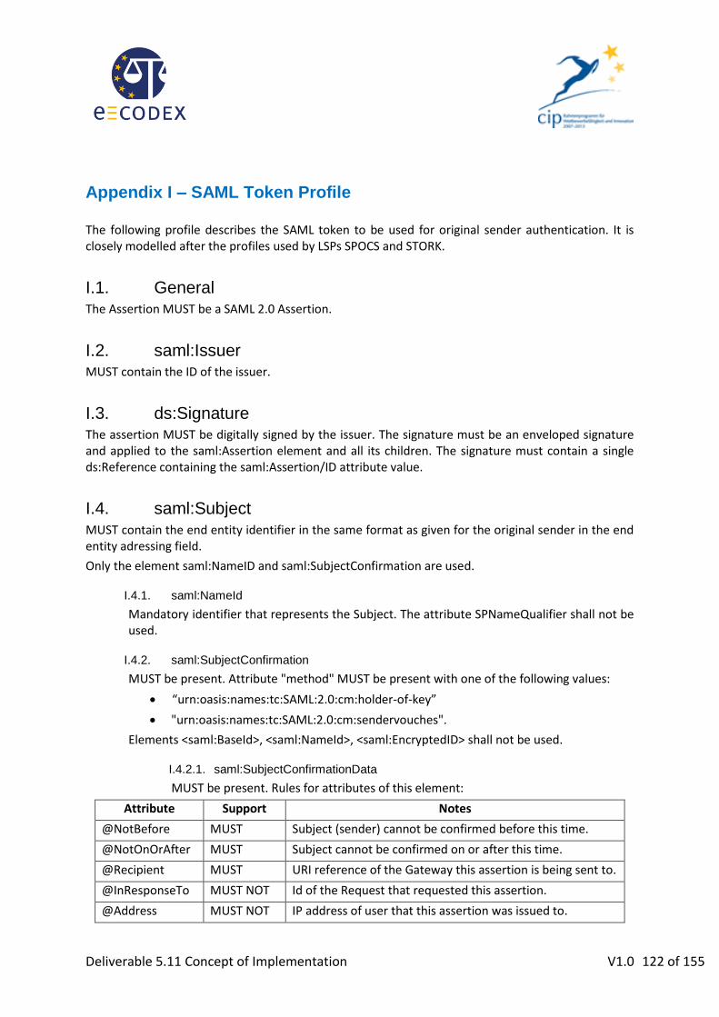
Deliverable 5.11 Concept of Implementation V1.0 122 of 155
Appendix I – SAML Token Profile
The following profile describes the SAML token to be used for original sender authentication. It is closely modelled after the profiles used by LSPs SPOCS and STORK.
I.1. General
The Assertion MUST be a SAML 2.0 Assertion.
I.2. saml:Issuer MUST contain the ID of the issuer.
I.3. ds:Signature The assertion MUST be digitally signed by the issuer. The signature must be an enveloped signature and applied to the saml:Assertion element and all its children. The signature must contain a single ds:Reference containing the saml:Assertion/ID attribute value.
I.4. saml:Subject
MUST contain the end entity identifier in the same format as given for the original sender in the end entity adressing field.
Only the element saml:NameID and saml:SubjectConfirmation are used.
I.4.1. saml:NameId
Mandatory identifier that represents the Subject. The attribute SPNameQualifier shall not be used.
I.4.2. saml:SubjectConfirmation
MUST be present. Attribute "method" MUST be present with one of the following values:
“urn:oasis:names:tc:SAML:2.0:cm:holder-of-key”
"urn:oasis:names:tc:SAML:2.0:cm:sendervouches".
Elements <saml:BaseId>, <saml:NameId>, <saml:EncryptedID> shall not be used.
I.4.2.1. saml:SubjectConfirmationData
MUST be present. Rules for attributes of this element:
Attribute Support Notes
@NotBefore MUST Subject (sender) cannot be confirmed before this time.
@NotOnOrAfter MUST Subject cannot be confirmed on or after this time.
@Recipient MUST URI reference of the Gateway this assertion is being sent to.
@InResponseTo MUST NOT Id of the Request that requested this assertion.
@Address MUST NOT IP address of user that this assertion was issued to.

Deliverable 5.11 Concept of Implementation V1.0 123 of 155
I.5. saml:Conditions
MUST be present. Rules for attributes of this element:
Attribute Support Notes
@NotBefore MUST Assertion not valid before this time.
@NotOnOrAfter MUST Assertion not valid on or after this time.
I.5.1. saml:AudienceRestriction
URI reference of the Gateway this assertion is being sent to.
I.6. saml:Advice Advice elements MAY safely be ignored by implementations.
I.7. saml:AuthnStatement MUST be present. Its attribute SessionIndex shall not be used. Element <saml:AuthnStatement>/<saml:SubjectLocality> shall not be used.
I.8. saml:AuthzDecisionStatement An Assertion MUST NOT contain an <AuthzDecisionStatement>.
I.9. saml:AttributeStatement e-CODEX: An Assertion MUST contain at least one <AttributeStatement>.
To provide information about the end entity’s initial registration process strength, the following <saml:Attribute> element is defined and may be provided:
@Name =
@NameFormat =
<saml:AttributeValue>: The value of the elements denotes the registration strength level.

Deliverable 5.11 Concept of Implementation V1.0 124 of 155
Appendix II – Backend Integration WSDL <?xml version="1.0" encoding="UTF-8"?>
<wsdl:definitions xmlns:xsd="http://www.w3.org/2001/XMLSchema"
xmlns:wsdl="http://schemas.xmlsoap.org/wsdl/"
xmlns:tns="http://org.ecodex.backend/1_1/"
xmlns:soap12="http://schemas.xmlsoap.org/wsdl/soap12/"
xmlns:ns2="http://schemas.xmlsoap.org/soap/http" xmlns:ns1="http://docs.oasis-
open.org/ebxml-msg/ebms/v3.0/ns/core/200704/" name="BackendService_1_1"
targetNamespace="http://org.ecodex.backend/1_1/">
<wsdl:types>
<xs:schema xmlns:xs="http://www.w3.org/2001/XMLSchema"
targetNamespace="http://www.w3.org/XML/1998/namespace" version="1.0">
<xs:attribute name="lang" type="xs:string"/>
</xs:schema>
<xs:schema xmlns:xs="http://www.w3.org/2001/XMLSchema"
xmlns:tns="http://www.w3.org/2005/05/xmlmime"
targetNamespace="http://www.w3.org/2005/05/xmlmime" version="1.0">
<xs:complexType name="base64Binary">
<xs:simpleContent>
<xs:extension base="xs:base64Binary">
<xs:attribute ref="tns:contentType"/>
</xs:extension>
</xs:simpleContent>
</xs:complexType>
<xs:complexType name="hexBinary">
<xs:simpleContent>
<xs:extension base="xs:string">
<xs:attribute ref="tns:contentType"/>
</xs:extension>
</xs:simpleContent>
</xs:complexType>
<xs:attribute name="contentType" type="xs:string"/>
</xs:schema>
<xs:schema xmlns:xs="http://www.w3.org/2001/XMLSchema"
xmlns:tns="http://www.w3.org/2003/05/soap-envelope"
xmlns:S12="http://www.w3.org/2003/05/soap-envelope" elementFormDefault="qualified"
targetNamespace="http://www.w3.org/2003/05/soap-envelope" version="1.0">
<xs:import namespace="http://www.w3.org/XML/1998/namespace"/>
<xs:element name="Body" type="tns:Body"/>
<xs:element name="Envelope" type="tns:Envelope"/>
<xs:element name="Fault" type="tns:Fault"/>
<xs:element name="Header" type="tns:Header"/>
<xs:element name="NotUnderstood" type="tns:NotUnderstoodType"/>
<xs:element name="Upgrade" type="tns:UpgradeType"/>
<xs:complexType name="Body">

Deliverable 5.11 Concept of Implementation V1.0 125 of 155
<xs:sequence>
<xs:any maxOccurs="unbounded" minOccurs="0" namespace="##other"
processContents="lax"/>
</xs:sequence>
<xs:anyAttribute namespace="##other" processContents="skip"/>
</xs:complexType>
<xs:complexType name="Envelope">
<xs:sequence>
<xs:element minOccurs="0" name="Header" type="tns:Header"/>
<xs:element name="Body" type="tns:Body"/>
</xs:sequence>
<xs:anyAttribute namespace="##other" processContents="skip"/>
</xs:complexType>
<xs:complexType name="Header">
<xs:sequence>
<xs:any maxOccurs="unbounded" minOccurs="0" namespace="##other"
processContents="lax"/>
</xs:sequence>
<xs:anyAttribute namespace="##other" processContents="skip"/>
</xs:complexType>
<xs:complexType name="detail">
<xs:sequence>
<xs:any maxOccurs="unbounded" minOccurs="0" namespace="##other"
processContents="lax"/>
</xs:sequence>
<xs:anyAttribute namespace="##other" processContents="skip"/>
</xs:complexType>
<xs:complexType name="faultcode">
<xs:sequence>
<xs:element name="Value" type="xs:QName"/>
<xs:element minOccurs="0" name="Subcode" type="tns:subcode"/>
</xs:sequence>
</xs:complexType>
<xs:complexType name="subcode">
<xs:sequence>
<xs:element name="Value" type="xs:QName"/>
<xs:element minOccurs="0" name="Subcode" type="tns:subcode"/>
</xs:sequence>
</xs:complexType>
<xs:complexType name="reasontext">
<xs:simpleContent>
<xs:extension base="xs:string">
<xs:attribute ref="xml:lang" use="required"/>
</xs:extension>
</xs:simpleContent>
</xs:complexType>
<xs:complexType name="UpgradeType">
<xs:sequence>
<xs:element maxOccurs="unbounded" name="SupportedEnvelope"
type="tns:SupportedEnvType"/>
</xs:sequence>
</xs:complexType>
<xs:complexType name="SupportedEnvType">
<xs:sequence/>
<xs:attribute name="qname" type="xs:QName" use="required"/>

Deliverable 5.11 Concept of Implementation V1.0 126 of 155
</xs:complexType>
<xs:complexType name="Fault">
<xs:sequence>
<xs:element name="Code" type="tns:faultcode"/>
<xs:element name="Reason" type="tns:faultreason"/>
<xs:element minOccurs="0" name="Node" type="xs:anyURI"/>
<xs:element minOccurs="0" name="Role" type="xs:anyURI"/>
<xs:element minOccurs="0" name="Detail" type="tns:detail"/>
</xs:sequence>
</xs:complexType>
<xs:complexType name="faultreason">
<xs:sequence>
<xs:element maxOccurs="unbounded" name="Text" type="tns:reasontext"/>
</xs:sequence>
</xs:complexType>
<xs:complexType name="NotUnderstoodType">
<xs:sequence/>
<xs:attribute name="qname" type="xs:QName" use="required"/>
</xs:complexType>
<xs:attribute name="mustUnderstand" type="xs:boolean"/>
</xs:schema>
<xs:schema xmlns:xs="http://www.w3.org/2001/XMLSchema"
xmlns:tns="http://schemas.xmlsoap.org/soap/envelope/"
xmlns:S11="http://schemas.xmlsoap.org/soap/envelope/"
targetNamespace="http://schemas.xmlsoap.org/soap/envelope/" version="1.0">
<xs:element name="Body" type="tns:Body"/>
<xs:element name="Envelope" type="tns:Envelope"/>
<xs:element name="Fault" type="tns:Fault"/>
<xs:element name="Header" type="tns:Header"/>
<xs:complexType name="Body">
<xs:sequence>
<xs:any maxOccurs="unbounded" minOccurs="0" namespace="##other"
processContents="lax"/>
</xs:sequence>
<xs:anyAttribute namespace="##other" processContents="skip"/>
</xs:complexType>
<xs:complexType name="Envelope">
<xs:sequence>
<xs:element form="qualified" minOccurs="0" name="Header" type="tns:Header"/>
<xs:element form="qualified" name="Body" type="tns:Body"/>
<xs:any maxOccurs="unbounded" minOccurs="0" namespace="##other"
processContents="lax"/>
</xs:sequence>
<xs:anyAttribute namespace="##other" processContents="skip"/>
</xs:complexType>
<xs:complexType name="Header">
<xs:sequence>
<xs:any maxOccurs="unbounded" minOccurs="0" namespace="##other"
processContents="lax"/>
</xs:sequence>
<xs:anyAttribute namespace="##other" processContents="skip"/>

Deliverable 5.11 Concept of Implementation V1.0 127 of 155
</xs:complexType>
<xs:complexType name="detail">
<xs:sequence>
<xs:any maxOccurs="unbounded" minOccurs="0" namespace="##other"
processContents="lax"/>
</xs:sequence>
<xs:anyAttribute namespace="##other" processContents="skip"/>
</xs:complexType>
<xs:complexType name="Fault">
<xs:sequence>
<xs:element name="faultcode" type="xs:QName"/>
<xs:element name="faultstring" type="xs:string"/>
<xs:element minOccurs="0" name="faultactor" type="xs:anyURI"/>
<xs:element minOccurs="0" name="detail" type="tns:detail"/>
</xs:sequence>
</xs:complexType>
</xs:schema>
<xs:schema xmlns:xs="http://www.w3.org/2001/XMLSchema"
xmlns:tns="http://org.ecodex.backend/1_1/"
xmlns:ns1="http://www.w3.org/2005/05/xmlmime" attributeFormDefault="unqualified"
elementFormDefault="unqualified" targetNamespace="http://org.ecodex.backend/1_1/">
<xs:import namespace="http://www.w3.org/2005/05/xmlmime"/>
<xs:element name="FaultDetail">
<xs:complexType>
<xs:sequence>
<xs:element name="code" type="xs:string"/>
<xs:element name="message" nillable="true" type="xs:string"/>
</xs:sequence>
</xs:complexType>
</xs:element>
<xs:element name="downloadMessageRequest">
<xs:complexType>
<xs:sequence>
<xs:element name="messageID" type="xs:string"/>
</xs:sequence>
</xs:complexType>
</xs:element>
<xs:element name="downloadMessageResponse">
<xs:complexType>
<xs:sequence>
<xs:element minOccurs="0" name="bodyload" type="tns:PayloadType"/>
<xs:element maxOccurs="unbounded" minOccurs="0" name="payload"
nillable="true" type="tns:PayloadType"/>
</xs:sequence>
</xs:complexType>
</xs:element>
<xs:element name="listPendingMessagesRequest" type="xs:anyType"/>
<xs:element name="listPendingMessagesResponse">
<xs:complexType>
<xs:sequence>
<xs:element maxOccurs="unbounded" minOccurs="0" name="messageID"
nillable="true" type="xs:string"/>
</xs:sequence>
</xs:complexType>
</xs:element>
<xs:element name="messageErrorsRequest">
<xs:complexType>
<xs:sequence>
<xs:element name="messageID" type="xs:string"/>
</xs:sequence>

Deliverable 5.11 Concept of Implementation V1.0 128 of 155
</xs:complexType>
</xs:element>
<xs:element name="messageStatusRequest">
<xs:complexType>
<xs:sequence>
<xs:element name="messageID" type="xs:string"/>
</xs:sequence>
</xs:complexType>
</xs:element>
<xs:element name="sendRequest">
<xs:complexType>
<xs:sequence>
<xs:element minOccurs="0" name="bodyload" type="tns:PayloadType"/>
<xs:element maxOccurs="unbounded" minOccurs="0" name="payload"
nillable="true" type="tns:PayloadType"/>
</xs:sequence>
</xs:complexType>
</xs:element>
<xs:element name="sendRequestURL">
<xs:complexType>
<xs:sequence>
<xs:element minOccurs="0" name="bodyload" type="tns:PayloadURLType"/>
<xs:element maxOccurs="unbounded" minOccurs="0" name="payload"
nillable="true" type="tns:PayloadURLType"/>
</xs:sequence>
</xs:complexType>
</xs:element>
<xs:element name="sendResponse">
<xs:complexType>
<xs:sequence>
<xs:element maxOccurs="unbounded" minOccurs="0" name="messageID"
nillable="true" type="xs:string"/>
</xs:sequence>
</xs:complexType>
</xs:element>
<xs:complexType name="PayloadType">
<xs:simpleContent>
<xs:extension base="ns1:base64Binary">
<xs:attribute name="payloadId" type="xs:token" use="required"/>
</xs:extension>
</xs:simpleContent>
</xs:complexType>
<xs:complexType name="errorLogEntry">
<xs:sequence>
<xs:element minOccurs="0" name="errorCode" type="tns:errorCode"/>
<xs:element minOccurs="0" name="errorDetail" type="xs:string"/>
<xs:element minOccurs="0" name="errorSignalMessageId" type="xs:string"/>
<xs:element minOccurs="0" name="messageInErrorId" type="xs:string"/>
<xs:element minOccurs="0" name="mshRole" type="tns:mshRole"/>
<xs:element minOccurs="0" name="notified" type="xs:dateTime"/>
<xs:element minOccurs="0" name="timestamp" type="xs:dateTime"/>
</xs:sequence>
</xs:complexType>
<xs:complexType name="PayloadURLType">
<xs:simpleContent>
<xs:extension base="xs:string">
<xs:attribute name="payloadId" type="xs:token" use="required"/>
</xs:extension>
</xs:simpleContent>
</xs:complexType>
<xs:simpleType name="messageStatus">
<xs:restriction base="xs:string">
<xs:enumeration value="SENT"/>
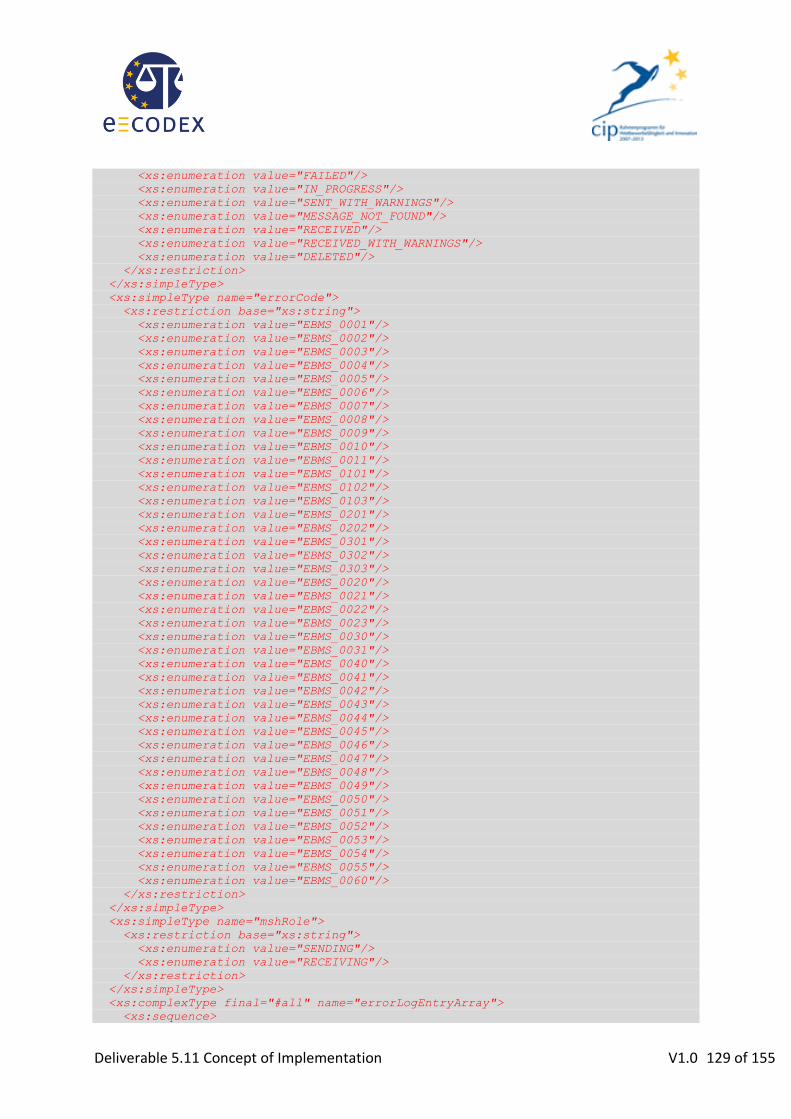
Deliverable 5.11 Concept of Implementation V1.0 129 of 155
<xs:enumeration value="FAILED"/>
<xs:enumeration value="IN_PROGRESS"/>
<xs:enumeration value="SENT_WITH_WARNINGS"/>
<xs:enumeration value="MESSAGE_NOT_FOUND"/>
<xs:enumeration value="RECEIVED"/>
<xs:enumeration value="RECEIVED_WITH_WARNINGS"/>
<xs:enumeration value="DELETED"/>
</xs:restriction>
</xs:simpleType>
<xs:simpleType name="errorCode">
<xs:restriction base="xs:string">
<xs:enumeration value="EBMS_0001"/>
<xs:enumeration value="EBMS_0002"/>
<xs:enumeration value="EBMS_0003"/>
<xs:enumeration value="EBMS_0004"/>
<xs:enumeration value="EBMS_0005"/>
<xs:enumeration value="EBMS_0006"/>
<xs:enumeration value="EBMS_0007"/>
<xs:enumeration value="EBMS_0008"/>
<xs:enumeration value="EBMS_0009"/>
<xs:enumeration value="EBMS_0010"/>
<xs:enumeration value="EBMS_0011"/>
<xs:enumeration value="EBMS_0101"/>
<xs:enumeration value="EBMS_0102"/>
<xs:enumeration value="EBMS_0103"/>
<xs:enumeration value="EBMS_0201"/>
<xs:enumeration value="EBMS_0202"/>
<xs:enumeration value="EBMS_0301"/>
<xs:enumeration value="EBMS_0302"/>
<xs:enumeration value="EBMS_0303"/>
<xs:enumeration value="EBMS_0020"/>
<xs:enumeration value="EBMS_0021"/>
<xs:enumeration value="EBMS_0022"/>
<xs:enumeration value="EBMS_0023"/>
<xs:enumeration value="EBMS_0030"/>
<xs:enumeration value="EBMS_0031"/>
<xs:enumeration value="EBMS_0040"/>
<xs:enumeration value="EBMS_0041"/>
<xs:enumeration value="EBMS_0042"/>
<xs:enumeration value="EBMS_0043"/>
<xs:enumeration value="EBMS_0044"/>
<xs:enumeration value="EBMS_0045"/>
<xs:enumeration value="EBMS_0046"/>
<xs:enumeration value="EBMS_0047"/>
<xs:enumeration value="EBMS_0048"/>
<xs:enumeration value="EBMS_0049"/>
<xs:enumeration value="EBMS_0050"/>
<xs:enumeration value="EBMS_0051"/>
<xs:enumeration value="EBMS_0052"/>
<xs:enumeration value="EBMS_0053"/>
<xs:enumeration value="EBMS_0054"/>
<xs:enumeration value="EBMS_0055"/>
<xs:enumeration value="EBMS_0060"/>
</xs:restriction>
</xs:simpleType>
<xs:simpleType name="mshRole">
<xs:restriction base="xs:string">
<xs:enumeration value="SENDING"/>
<xs:enumeration value="RECEIVING"/>
</xs:restriction>
</xs:simpleType>
<xs:complexType final="#all" name="errorLogEntryArray">
<xs:sequence>

Deliverable 5.11 Concept of Implementation V1.0 130 of 155
<xs:element maxOccurs="unbounded" minOccurs="0" name="item" nillable="true"
type="tns:errorLogEntry"/>
</xs:sequence>
</xs:complexType>
<xs:element name="getStatusRequest" nillable="true">
<xs:complexType>
<xs:sequence>
<xs:element name="messageID" type="xs:string"/>
</xs:sequence>
</xs:complexType>
</xs:element>
<xs:element name="getMessageStatusResponse" nillable="true"
type="tns:messageStatus"/>
<xs:element name="getErrorsRequest" nillable="true">
<xs:complexType>
<xs:sequence>
<xs:element name="messageID" type="xs:string"/>
</xs:sequence>
</xs:complexType>
</xs:element>
<xs:element name="getMessageErrorsResponse" nillable="true"
type="tns:errorLogEntryArray"/>
</xs:schema>
<xs:schema xmlns:xs="http://www.w3.org/2001/XMLSchema"
xmlns:tns="http://docs.oasis-open.org/ebxml-msg/ebms/v3.0/ns/core/200704/"
xmlns:ns1="http://www.w3.org/2003/05/soap-envelope" xmlns:eb="http://docs.oasis-
open.org/ebxml-msg/ebms/v3.0/ns/core/200704/" elementFormDefault="qualified"
targetNamespace="http://docs.oasis-open.org/ebxml-msg/ebms/v3.0/ns/core/200704/"
version="1.0">
<xs:import namespace="http://www.w3.org/2003/05/soap-envelope"/>
<xs:import namespace="http://www.w3.org/XML/1998/namespace"/>
<xs:element name="Messaging" type="tns:Messaging"/>
<xs:element name="UserMessage" type="tns:UserMessage"/>
<xs:complexType name="Messaging">
<xs:sequence>
<xs:element minOccurs="0" name="SignalMessage" type="tns:SignalMessage"/>
<xs:element minOccurs="0" name="UserMessage" type="tns:UserMessage"/>
<xs:any maxOccurs="unbounded" minOccurs="0" namespace="##other"
processContents="lax"/>
</xs:sequence>
<xs:attribute name="id" type="xs:ID"/>
<xs:attribute ref="ns1:mustUnderstand"/>
<xs:anyAttribute namespace="##other" processContents="skip"/>
</xs:complexType>
<xs:complexType name="SignalMessage">
<xs:sequence>
<xs:element name="MessageInfo" type="tns:MessageInfo"/>
<xs:element minOccurs="0" name="PullRequest" type="tns:PullRequest"/>
<xs:element minOccurs="0" name="Receipt" type="tns:Receipt"/>
<xs:element maxOccurs="unbounded" minOccurs="0" name="Error"
type="tns:Error"/>
<xs:any maxOccurs="unbounded" minOccurs="0" namespace="##other"
processContents="lax"/>
</xs:sequence>
</xs:complexType>
<xs:complexType name="MessageInfo">

Deliverable 5.11 Concept of Implementation V1.0 131 of 155
<xs:sequence>
<xs:element name="Timestamp" type="xs:dateTime"/>
<xs:element name="MessageId" type="xs:string"/>
<xs:element minOccurs="0" name="RefToMessageId" type="xs:string"/>
</xs:sequence>
</xs:complexType>
<xs:complexType name="PullRequest">
<xs:sequence>
<xs:any maxOccurs="unbounded" minOccurs="0" namespace="##other"
processContents="lax"/>
</xs:sequence>
<xs:attribute name="mpc" type="xs:anyURI"/>
<xs:anyAttribute namespace="##other" processContents="skip"/>
</xs:complexType>
<xs:complexType name="Service">
<xs:simpleContent>
<xs:extension base="xs:string">
<xs:attribute name="type" type="xs:string"/>
</xs:extension>
</xs:simpleContent>
</xs:complexType>
<xs:complexType name="From">
<xs:sequence>
<xs:element maxOccurs="unbounded" name="PartyId" type="tns:PartyId"/>
<xs:element default="http://docs.oasis-open.org/ebxml-
msg/ebms/v3.0/ns/core/200704/defaultRole" name="Role" type="xs:string"/>
</xs:sequence>
</xs:complexType>
<xs:complexType name="PartyId">
<xs:simpleContent>
<xs:extension base="xs:string">
<xs:attribute name="type" type="xs:string"/>
</xs:extension>
</xs:simpleContent>
</xs:complexType>
<xs:complexType name="Schema">
<xs:sequence/>
<xs:attribute name="location" type="xs:anyURI" use="required"/>
<xs:attribute name="version" type="xs:string"/>
<xs:attribute name="namespace" type="xs:string"/>
</xs:complexType>
<xs:complexType name="To">
<xs:sequence>
<xs:element maxOccurs="unbounded" name="PartyId" type="tns:PartyId"/>
<xs:element default="http://docs.oasis-open.org/ebxml-
msg/ebms/v3.0/ns/core/200704/defaultRole" name="Role" type="xs:string"/>
</xs:sequence>
</xs:complexType>
<xs:complexType name="Property">
<xs:simpleContent>
<xs:extension base="xs:string">
<xs:attribute name="name" type="xs:string" use="required"/>
</xs:extension>
</xs:simpleContent>
</xs:complexType>

Deliverable 5.11 Concept of Implementation V1.0 132 of 155
<xs:complexType name="PartyInfo">
<xs:sequence>
<xs:element name="From" type="tns:From"/>
<xs:element name="To" type="tns:To"/>
</xs:sequence>
</xs:complexType>
<xs:complexType name="Error">
<xs:sequence>
<xs:element minOccurs="0" name="Description" type="tns:Description"/>
<xs:element minOccurs="0" name="ErrorDetail" type="xs:token"/>
</xs:sequence>
<xs:attribute name="category" type="xs:token"/>
<xs:attribute name="refToMessageInError" type="xs:token"/>
<xs:attribute name="errorCode" type="xs:token" use="required"/>
<xs:attribute name="origin" type="xs:token"/>
<xs:attribute name="severity" type="xs:token" use="required"/>
<xs:attribute name="shortDescription" type="xs:token"/>
</xs:complexType>
<xs:complexType name="Description">
<xs:simpleContent>
<xs:extension base="xs:string">
<xs:attribute ref="xml:lang" use="required"/>
</xs:extension>
</xs:simpleContent>
</xs:complexType>
<xs:complexType name="PartInfo">
<xs:sequence>
<xs:element minOccurs="0" name="Schema" type="tns:Schema"/>
<xs:element minOccurs="0" name="Description" type="tns:Description"/>
<xs:element minOccurs="0" name="PartProperties" type="tns:PartProperties"/>
</xs:sequence>
<xs:attribute name="href" type="xs:token"/>
</xs:complexType>
<xs:complexType name="PartProperties">
<xs:sequence>
<xs:element maxOccurs="unbounded" name="Property" type="tns:Property"/>
</xs:sequence>
</xs:complexType>
<xs:complexType name="Receipt">
<xs:sequence>
<xs:any namespace="##other" processContents="skip"/>
</xs:sequence>
</xs:complexType>
<xs:complexType name="CollaborationInfo">
<xs:sequence>
<xs:element minOccurs="0" name="AgreementRef" type="tns:AgreementRef"/>
<xs:element name="Service" type="tns:Service"/>
<xs:element name="Action" type="xs:token"/>
<xs:element name="ConversationId" type="xs:token"/>
</xs:sequence>
</xs:complexType>
<xs:complexType name="AgreementRef">
<xs:simpleContent>
<xs:extension base="xs:string">
<xs:attribute name="type" type="xs:string"/>
<xs:attribute name="pmode" type="xs:string"/>

Deliverable 5.11 Concept of Implementation V1.0 133 of 155
</xs:extension>
</xs:simpleContent>
</xs:complexType>
<xs:complexType name="MessageProperties">
<xs:sequence>
<xs:element maxOccurs="unbounded" name="Property" type="tns:Property"/>
</xs:sequence>
</xs:complexType>
<xs:complexType name="PayloadInfo">
<xs:sequence>
<xs:element maxOccurs="unbounded" name="PartInfo" type="tns:PartInfo"/>
</xs:sequence>
</xs:complexType>
<xs:complexType name="UserMessage">
<xs:sequence>
<xs:element name="MessageInfo" type="tns:MessageInfo"/>
<xs:element name="PartyInfo" type="tns:PartyInfo"/>
<xs:element name="CollaborationInfo" type="tns:CollaborationInfo"/>
<xs:element minOccurs="0" name="MessageProperties"
type="tns:MessageProperties"/>
<xs:element minOccurs="0" name="PayloadInfo" type="tns:PayloadInfo"/>
</xs:sequence>
<xs:attribute name="mpc" type="xs:anyURI"/>
</xs:complexType>
</xs:schema>
</wsdl:types>
<wsdl:message name="listPendingMessages">
<wsdl:part element="tns:listPendingMessagesRequest"
name="listPendingMessagesRequest">
</wsdl:part>
</wsdl:message>
<wsdl:message name="listPendingMessagesResponse">
<wsdl:part element="tns:listPendingMessagesResponse"
name="listPendingMessagesResponse">
</wsdl:part>
</wsdl:message>
<wsdl:message name="SendMessageFault">
<wsdl:part element="tns:FaultDetail" name="SendMessageFault">
</wsdl:part>
</wsdl:message>
<wsdl:message name="getMessageErrorsResponse">
<wsdl:part element="tns:getMessageErrorsResponse"
name="getMessageErrorsResponse">
</wsdl:part>
</wsdl:message>
<wsdl:message name="sendMessage">
<wsdl:part element="tns:sendRequest" name="sendRequest">
</wsdl:part>
<wsdl:part element="ns1:Messaging" name="ebMSHeaderInfo">
</wsdl:part>
</wsdl:message>
<wsdl:message name="downloadMessage">
<wsdl:part element="tns:downloadMessageRequest" name="downloadMessageRequest">
</wsdl:part>
</wsdl:message>
<wsdl:message name="downloadMessageResponse">
<wsdl:part element="tns:downloadMessageResponse"
name="downloadMessageResponse">
</wsdl:part>
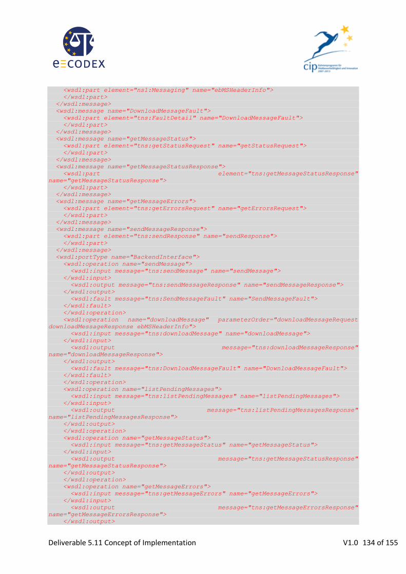
Deliverable 5.11 Concept of Implementation V1.0 134 of 155
<wsdl:part element="ns1:Messaging" name="ebMSHeaderInfo">
</wsdl:part>
</wsdl:message>
<wsdl:message name="DownloadMessageFault">
<wsdl:part element="tns:FaultDetail" name="DownloadMessageFault">
</wsdl:part>
</wsdl:message>
<wsdl:message name="getMessageStatus">
<wsdl:part element="tns:getStatusRequest" name="getStatusRequest">
</wsdl:part>
</wsdl:message>
<wsdl:message name="getMessageStatusResponse">
<wsdl:part element="tns:getMessageStatusResponse"
name="getMessageStatusResponse">
</wsdl:part>
</wsdl:message>
<wsdl:message name="getMessageErrors">
<wsdl:part element="tns:getErrorsRequest" name="getErrorsRequest">
</wsdl:part>
</wsdl:message>
<wsdl:message name="sendMessageResponse">
<wsdl:part element="tns:sendResponse" name="sendResponse">
</wsdl:part>
</wsdl:message>
<wsdl:portType name="BackendInterface">
<wsdl:operation name="sendMessage">
<wsdl:input message="tns:sendMessage" name="sendMessage">
</wsdl:input>
<wsdl:output message="tns:sendMessageResponse" name="sendMessageResponse">
</wsdl:output>
<wsdl:fault message="tns:SendMessageFault" name="SendMessageFault">
</wsdl:fault>
</wsdl:operation>
<wsdl:operation name="downloadMessage" parameterOrder="downloadMessageRequest
downloadMessageResponse ebMSHeaderInfo">
<wsdl:input message="tns:downloadMessage" name="downloadMessage">
</wsdl:input>
<wsdl:output message="tns:downloadMessageResponse"
name="downloadMessageResponse">
</wsdl:output>
<wsdl:fault message="tns:DownloadMessageFault" name="DownloadMessageFault">
</wsdl:fault>
</wsdl:operation>
<wsdl:operation name="listPendingMessages">
<wsdl:input message="tns:listPendingMessages" name="listPendingMessages">
</wsdl:input>
<wsdl:output message="tns:listPendingMessagesResponse"
name="listPendingMessagesResponse">
</wsdl:output>
</wsdl:operation>
<wsdl:operation name="getMessageStatus">
<wsdl:input message="tns:getMessageStatus" name="getMessageStatus">
</wsdl:input>
<wsdl:output message="tns:getMessageStatusResponse"
name="getMessageStatusResponse">
</wsdl:output>
</wsdl:operation>
<wsdl:operation name="getMessageErrors">
<wsdl:input message="tns:getMessageErrors" name="getMessageErrors">
</wsdl:input>
<wsdl:output message="tns:getMessageErrorsResponse"
name="getMessageErrorsResponse">
</wsdl:output>

Deliverable 5.11 Concept of Implementation V1.0 135 of 155
</wsdl:operation>
</wsdl:portType>
<wsdl:binding name="BackendService_1_1SoapBinding" type="tns:BackendInterface">
<soap12:binding style="document"
transport="http://schemas.xmlsoap.org/soap/http"/>
<wsdl:operation name="sendMessage">
<soap12:operation soapAction="" style="document"/>
<wsdl:input name="sendMessage">
<soap12:header message="tns:sendMessage" part="ebMSHeaderInfo"
use="literal">
</soap12:header>
<soap12:body parts="sendRequest" use="literal"/>
</wsdl:input>
<wsdl:output name="sendMessageResponse">
<soap12:body use="literal"/>
</wsdl:output>
<wsdl:fault name="SendMessageFault">
<soap12:fault name="SendMessageFault" use="literal"/>
</wsdl:fault>
</wsdl:operation>
<wsdl:operation name="downloadMessage">
<soap12:operation soapAction="" style="document"/>
<wsdl:input name="downloadMessage">
<soap12:body use="literal"/>
</wsdl:input>
<wsdl:output name="downloadMessageResponse">
<soap12:header message="tns:downloadMessageResponse" part="ebMSHeaderInfo"
use="literal">
</soap12:header>
<soap12:body parts="downloadMessageResponse" use="literal"/>
</wsdl:output>
<wsdl:fault name="DownloadMessageFault">
<soap12:fault name="DownloadMessageFault" use="literal"/>
</wsdl:fault>
</wsdl:operation>
<wsdl:operation name="listPendingMessages">
<soap12:operation soapAction="" style="document"/>
<wsdl:input name="listPendingMessages">
<soap12:body use="literal"/>
</wsdl:input>
<wsdl:output name="listPendingMessagesResponse">
<soap12:body use="literal"/>
</wsdl:output>
</wsdl:operation>
<wsdl:operation name="getMessageStatus">
<soap12:operation soapAction="" style="document"/>
<wsdl:input name="getMessageStatus">
<soap12:body use="literal"/>
</wsdl:input>
<wsdl:output name="getMessageStatusResponse">
<soap12:body use="literal"/>
</wsdl:output>
</wsdl:operation>
<wsdl:operation name="getMessageErrors">
<soap12:operation soapAction="" style="document"/>
<wsdl:input name="getMessageErrors">
<soap12:body use="literal"/>
</wsdl:input>
<wsdl:output name="getMessageErrorsResponse">
<soap12:body use="literal"/>
</wsdl:output>
</wsdl:operation>
</wsdl:binding>

Deliverable 5.11 Concept of Implementation V1.0 136 of 155
<wsdl:service name="BackendService_1_1">
<wsdl:port binding="tns:BackendService_1_1SoapBinding" name="BACKEND_PORT">
<soap12:address location="http://localhost:8080/domibus/services/backend"/>
</wsdl:port>
</wsdl:service>
</wsdl:definitions>

Deliverable 5.11 Concept of Implementation V1.0 137 of 155
Appendix III – P-Mode Configuration86
Note that parameter names in Holodeck are not the same as given in the ebMS3 specification.
Parameter Usage in e-CODEX PMode.MEP http://docs.oasis-open.org/ebxml-
msg/ebms/v3.0/ns/core/200704/oneWay
PMode.MEPbinding http://docs.oasis-open.org/ebxml-msg/ebms/v3.0/ns/core/200704/push
PMode.Initiator.Role Default value:
http://docs.oasis-open.org/ebxml-msg/ebms/v3.0/ns/core/200704/initiator
PMode.Responder.Role Default value:
http://docs.oasis-open.org/ebxml-msg/ebms/v3.0/ns/core/200704/responder
PMode[1].Protocol.SOAPVersion 1.2
PMode[1].BusinessInfo.Service Will have a value that is constructed as follows:
http://e-justice.europa.eu/[name-of-use-case] PMode[1].BusinessInfo.Action Will have a value that is constructed as follows:
http://e-justice.europa.eu/[name-of-form] PMode[1].BusinessInfo.Properties[] PMode[1].BusinessInfo. PayloadProfile[] Will be used to specify which message parts are
mandatory (see section 0 “It has been decided in e-CODEX WP4 that the so-called “Trust-OK token” (which gives information about signature verification and/or user authentication in human-readable form) should be packaged together with the signed documents in a container. Therefore the whole container is just one attachment. The XML version of the “Trust-OK token”, which is not packaged, will be treated similar to the SAML token as a separate message part.
Summary: Message parts”). PMode[1].BusinessInfo.PayloadProfile.maxSize Will for each communication partner (MS) be set
to the maximum message size admissible to the corresponding national solution.
PMode[1].BusinessInfo.MPC Will not be used.
86
As far as these parameter values aren’t e-CODEX specific, they correspond to the recommendations in the AS4 profile (http://docs.oasis-open.org/ebxml-msg/ebms/v3.0/profiles/AS4-profile/v1.0/csprd03/AS4-profile-v1.0-csprd03.odt).

Deliverable 5.11 Concept of Implementation V1.0 138 of 155
III.1. Reliability Reliability will be based on AS4 reliability.
PMode[1].ReceptionAwareness true PMode[1].ReceptionAwareness.Retry true PMode[1].ReceptionAwareness.Retry.Parameters “maxretries=10;
period=20000; shutdown=60000”
PMode[1].Security.SendReceipt true PMode[1].Security.SendReceipt.NonRepudiation false PMode[1].Security.SendReceipt.ReplyPattern “Response” or “Callback” PMode[1].Security.SendReceipt.ReceiptTo URI of the sending MSH PMode[1].Security.SendReceipt.DeliverySemantics “Received” or “Downloaded” PMode[1].ReceptionAwareness.DuplicateDetection true
III.2. Security PMode[1].Security.WSSVersion 1.1 PMode[1].Security.X509.Sign.Element[] PMode[1].Security.X509.Sign.Attachment[] PMode[1].Security.X509.Signature.Certificate PMode[1].Security.X509.Signature.HashFunction PMode[1].Security.X509.Signature.Algorithm PMode[1].Security.X509.Encryption.Encrypt.Element[] PMode[1].Security.X509.Encryption.Encrypt.Attachment[] PMode[1].Security.X509.Encryption.Certificate PMode[1].Security.X509.Encryption.Algorithm PMode[1].Security.X509.Encryption.MinimumStrength PMode[1].Security.UsernameToken.username PMode[1].Security.UsernameToken.password PMode[1].Security.UsernameToken.Digest PMode[1].Security.UsernameToken.Nonce PMode[1].Security.UsernameToken.Created PModeAuthorize PMode[1].Security.SendReceipt false Pmode[1].Security.SendReceipt.ReplyPattern not used
III.3. Other Required Features

Deliverable 5.11 Concept of Implementation V1.0 139 of 155
Any ebMS3 messaging product (possibly other than Holodeck) that would be connected to the European Transport Infrastructure needs (in addition to the settings mentioned in the previous
section) to support at least87
:
Attachments
87
Note that this list is not exhaustive and may grow over time.

Deliverable 5.11 Concept of Implementation V1.0 140 of 155
Appendix IV – e-Justice portal templates for payment information from MS
PAYMENT OF COURT FEES CONCERNING EUROPEAN PAYMENT ORDER- [MS]
Introduction [Quote the national regulation regarding the payment of court fees concerning EPO.]
[Indicate whether electronic payment of fees is available]
What fees are applicable?
[Explain to the citizen if payment of court fees is required and in which processes (specific EPO forms/actions/etc.)]
[Include references to national regulations if required to understand the appropriate national court fees]
How much shall I pay?
[This point should answer the question ‘how much must be paid for each process described above?’. In case calculations are to be done these should be explained here]
What happens if I do not pay the court fees on time? [Explain to the citizen the consequences on the EPO process if payment of fees is not done or if no evidence of is available for the court to check that payment has been done]
How can I pay the court fees? *This point should answer the question ‘how to pay court fees?’, providing all possibilities with examples. In order to align with the European EPO regulation (section 5.) this section should include following points:
a) Bank Transfer
b) Credit Card
c) Direct Debit from bank account (collection by court)
d) Other
For each point, it should be clearly indicated if a specific option is available and all necessary details per each option.]
[In case of electronic payment option, explain it as well. Link to the electronic payment system must be provided]
[In case of availability of Legal aid for payment of court fees, it should also be mentioned here as well.]

Deliverable 5.11 Concept of Implementation V1.0 141 of 155
What shall I do after the payment? [Describe the evidence the citizen should obtain from the payment act: information included, format, appearance, size, etc. Detail the requirements for this evidence to be valid in front of the court. Concerns all payment methods described in the paragraph "paying court fees" above – including electronic payment option.]
[Explanation on how to send the payment evidence to the court, usually attached to the process form.]
<related-links>
[Please, include rollover text for this links according to quality requirements for the e-Justice Portal]
(Link to the appropriate national regulations)
(Link to the appropriate e-Payment solution)
</related-links>
<keywords> court fees, electronic payment, payment evidence, receipt, judicial process </keywords>

Deliverable 5.11 Concept of Implementation V1.0 142 of 155
PAYMENT OF COURT FEES CONCERNING SMALL CLAIMS- [MS]
Introduction [Quote the national regulation regarding the payment of court fees concerning Small Claims.]
[Indicate whether electronic payment of fees is available]
What fees are applicable?
[Explain to the citizen if payment of court fees is required and in which processes (specific Small Claims forms/actions/etc.)]
[Include references (links) to national regulations if required to understand the appropriate national court fees]
How much shall I pay? *This point should answer the question ‘how much must be paid for each process described above?’. In case calculations are to be done these should be explained here]
What happens if I do not pay the court fees on time? [Explain to the citizen the consequences on the Small Claims process if payment of fees is not done or if no evidence of is available for the court to check that payment has been done]
How can I pay the court fees? *This point should answer the question ‘how to pay court fees?’, providing all possibilities with examples. In order to align with the European Small Claims regulation (section 6.) this section should include following points:
a) Bank Transfer
b) Credit Card
c) Direct Debit from bank account (collection by court)
d) Other
For each point, it should be clearly indicated if a specific option is available and all necessary details per each option.]
[In case of electronic payment option, explain it as well. Link to the electronic payment system must be provided]
[In case of availability of Legal aid for payment of court fees, it should also be mentioned here as well.]
What shall I do after the payment? [Describe the evidence the citizen should obtain from the payment act: information included, format, appearance, size, etc. Detail the requirements for this evidence to be valid in front of the court.

Deliverable 5.11 Concept of Implementation V1.0 143 of 155
Concerns all payment methods described in the paragraph "paying court fees" above – including electronic payment option.]
[Explanation on how to send the payment evidence to the court, usually attached to the process form.]
<related-links>
[Please, include rollover text for this links according to quality requirements for the e-Justice Portal]
(Link to the appropriate national regulations)
(Link to the appropriate e-Payment solution)
</related-links>
<keywords> court fees, electronic payment, payment evidence, receipt, judicial process </keywords>
Deliverable 5.11 Concept of Implementation V1.0 144 of 155
Appendix V – Information about e-Payment from MS
V.1. e-Payment in Austria (AT)
Austria uses direct debit transactions for automatic collection of court fees for electronically filed cases.
This means – in addition to the case data- the claimant (or his lawyer/representative) has to specify IBAN, BIC and the account holder name of his bank account number, which is to be used for the automatic withdrawal of court fees. The back office application of the Austrian courts then calculates the required court fees automatically and collects the required amount for court fees from the specified bank account of the claimant automatically via a direct debit transaction.
The Austrian back-office application for the courts currently uses national direct debit transactions. For e-CODEX this needs to be extended by using SEPA cross-border direct debit transactions.
Important prerequisites:
All electronic claim forms, which can start a cross-border case to be processed by an Austrian court, must contain input fields to specify the bank account number (IBAN, BIC, name of account holder) of the claimant (or his lawyer/representative) to be used for withdrawal of court fees.
Note:
The Form A for the European Order for Payment Procedure already contains these fields.
The forms for the other e-CODEX use cases need to be checked!
V.2. e-Payment in Germany (DE)
V.2.1. General remarks
In Germany pre-payment of Court fees is mandatory. Later payment is not considered feasible (neither for court fees nor for other applications in the judicial domain where payment is required) because of the organizational arrangements this would imply.
Therefore bank transfer and credit card payment are of interest as payment methods. Among these, credit card payment is often preferred because it is immediate, whereas for bank transfer the goods or services that are being paid for need to be held until payment arrives.
In the “Land” North Rhine-Westphalia, the following online procedures which use different payment methods are currently offered:
Electronic voucher for payment of court fees: bank transfer or credit card
Online auction platform of the Justice of North Rhine-Westphalia : Pre-Paid via bank transfer
Information from trade register via the internet for registered users: monthly account; direct debit is possible
Information from land register via the internet for admitted users and authorities: monthly account; direct debit is possible
For e-CODEX, the first of the above solution (electronic voucher: “Kostenmarke”) will be used.
Deliverable 5.11 Concept of Implementation V1.0 145 of 155
V.2.2. Electronic voucher for payment of court fees
For the “Elektronische Kostenmarke” (electronic voucher for payment of court fees) the procedure is as follows:
In a web application (www.kostenmarke.justiz.de) users can purchase a voucher.
Accepted payment methods are bank transfer and credit card.
A unique identifier is generated, which corresponds to a specific amount of money.
The receipt contains this unique identifier and a corresponding bar code.
After reception of payment, this unique identifier will in the database be tagged as “paid”. (Successful payment by credit card is considered immediate reception of payment)
For a given receipt with its unique identifier submitted to a court, the court clerk can via another web application check if this identifier is tagged “paid”.
Only if this is the case the proceeding is continued.
V.3. e-Payment in Spain (ES)
V.3.1. Judicial fees
In Spain it is not necessary to pay fees to start a trial.
Spanish citizens do not need to pay fees, costs are covered by taxes, justice is free by law in Spain.
V.3.2. Payments arisen from judicial processes
All payments associated with the development of the judicial process is carried out through an existing bank account number for each court (called ‘Appropriation Account’, and there is one per court), besides it’s necessary to include a special code that the Court gives you and it’s associate to the judicial process.
The management of the payments is made through an application for the Judicial Secretaries. They can consult and review all payments in their Appropriation Account.
We have national regulations for all such payments:
RD 467/2006, 21 April, by regulating the judicial appropriations cash deposits, effects or values.
ORDEN JUS/1623/2007, 4 April, by adopting the model forms of income payment orders and transfer orders governed by the RD 467/2006.
V.4. e-Payment in France (FR)
France sent a proposal for an e-Payment approach: it would consist on a central portal where the user is redirected to the national e-Payment solution and receive a stamp after the execution of payment.
In order to pay a tax, the citizen will add the number of the stamp in the form.

Deliverable 5.11 Concept of Implementation V1.0 146 of 155
Figure 49 – France proposal of a central interface
Figure 50 – Tax stamp proposal
V.5. e-Payment in Italy (IT)
V.5.1. Introduction
The Italian system is valid for the payment of taxes by individuals for the benefit of the public administration in order to cover management expenses of proceedings (court costs) or to obtain a service (registration, copy paper, certificate, notifications, etc).
The service is subject to verification of payment.
Purchase of digital tax stamps
Purchase of digital tax stamps

Deliverable 5.11 Concept of Implementation V1.0 147 of 155
V.5.2. Phases
The process of electronic payment for Justice costs is divided conceptually into two distinct and independent stages:
1) A phase in which the subject interacts with the Justice domain to request the service
2) and a phase in which the payer interacts with the domain of the financial intermediates (or providers of payment services) to perform the payment of the requested sums.
The two phases, depending on the type of service provided, may be strictly sequential or interleaved in a single stream.
A subject can perform an electronic payment independently by the level of computerization of the courts office: an electronic payment can be accepted and validated in a traditional way.
The financial intermediates are banks and the Italian Postal Service.
Payment phase: the payer performs the electronic payment through a channel that provides the requirements for identification, authorization, and integrity of payment data. The electronic channel gives the payer the ability to use different means for payment, such as debit cards, credit cards, prepaid cards or other means of payment by electronic money.
Through the same channel the subject receives the electronic payment receipt.
Service phase: the subject requires the service. Depending on the type of service, the payment receipt will be forwarded to the office through electronic channel or in traditional mode (paper). The court office verifies the integrity of the receipt, preserves it and provides the requested service.
In case of synchronous service, the two processes are managed through protocols and interoperability in a fully automated flow to meet the demands of the payer in an integrated and transparent way.
V.5.3. Logic and functional model
The steps outlined above, while remaining independent and asynchronous, require the definition of information shared between the two areas (financial and Justice), and agreement on protocols and application logic.
To implement the interaction between different systems within a single business process, ensuring the independence of each domain in order to architectural choices, infrastructure, formats and streams, a logic-functional component, the Payment Gateway, has been introduced; it provides sharing capabilities of protocols (application and transport) and transformation of formats making the decoupling of infrastructures and functions between the financial domain and the Justice domain.

Deliverable 5.11 Concept of Implementation V1.0 148 of 155
SOA model was adopted as a paradigm for interoperability between applications, each under the control of different domains.
(following the picture’s numeration)
Payment Phase
1. The external subject gets access to the payment service through strong authentication on his/her Access Point.88
2. The E-Justice system provides a unique identifier to be associated to the payment procedure (Creditor Reference - ISO 11694 – is used). This information has to be put into the electronic payment receipt.
3. Data related to the payment (amount, recipient, causal, ...) are transmitted through the exchange of XML structured data to the "payment Gateway" which, as shown, defines the Gateway to the domain of entities providing the payment services.
4. Within the “banking world”, the Gateway shall generate a request for transfer according to the SEPA standards and manages and interprets the typical flows of bank transactions. The payment is completed within the systems of the provider of payment services according to their typical work flows.
88 The Access Point is authorized by the Ministry of Justice and has the responsibility to e-Identify external users

Deliverable 5.11 Concept of Implementation V1.0 149 of 155
5. Once the payment is completed, the Gateway generates a receipt of payment in the form of structured interchange file (XML format) according to an XSD defined in the Justice domain. The payment receipt is digitally signed.
6. The payment receipt is stored in a special file system ( “archive of the receipts”) managed by the Ministry of Justice.
7. The receipt of payment is returned to the payer.
Service Phase
8. The subject sends the receipt to the Court together with the request of service or the indication of the reason for the payment. This can be sent using the electronic channel, if available at the office, or in the traditional way (paper).
9. The court’s system checks the integrity of the payment receipt (e-Signature of receipt), verifies that the receipt states the correct charge and that it has never been used before. The archive of the receipts allows avoiding interaction with the systems of the financial domain to cross-check.
10. The Court accepts the payment and provides the requested service.
V.5.4. Archive of the receipts
The definition of the component “archive of the receipts” allows systems in Courts to verify the payments made independently from the processing state of the economic transaction (reconciliation, reporting, etc.).
Please note that this mode of operation is assured by special legal provisions related to payments made to the State Treasury and the means of payment accepted. Under those provisions, in fact, the payment is effectively made when the financial subject charges the sum on the bank account of the payer.
This component also allows the storage of the statements made by local providers of payment services and the consequent implementation of analysis of data on payments to Justice.
V.6. e-Payment in The Netherlands (NL)
The current situation in the Netherlands regarding the collection of court fees via e-Payment is that there is a pilot, not a fully implemented system. Bailiffs, barristers and lawyers connected to the courts in The Hague and Amsterdam receive, if participating in this pilot, digital invoices via a Biller Service Provider (BSP). The courts deliver the BSP the invoices for the court fees. The BSP deals thereupon with the bailiffs, barristers and lawyers. Successful fee collection is not a prerequisite in all cases to have access to the legal procedure. In those cases the fee can be paid afterwards as well. The payment process is not expected to use the e-banking facilities that banks provide their customers with. For bailiffs, barristers and lawyers the possibility to use batch procedures for multiple transactions is highly desirable. This service is not open to private citizens.
During this pilot, maybe afterwards as well and maybe the debtor decides on the way payments are done. BSP is the agent sending the invoice to the debtors if payment to the courts is done electronically. Apart from e-Payment cash payments are right as well. The Financial administration system of the courts is not yet ready for dealing with e-Payment smoothly. Improvements are expected mid next year with the introduction of a new Financial system.

Deliverable 5.11 Concept of Implementation V1.0 150 of 155
It may be clear from this short notice that courts in the Netherlands are progressing in using e-Payment for collecting court fees. It should also be clear that the experiences so far are limited and a lot can be learned from our colleagues in e-CODEX.
V.7. e-Payment in Portugal (PT)
V.7.1. Introduction
In Portugal there are two situations for which e-Payment is available:
1. Order for payment procedure, available only for lawyers/solicitors 2. General, available to everyone
The payment of taxes in order to cover management expenses of proceedings (court costs) is always prior to the process filing. The latter is subject to the verification of payment.
The process for each of these situations is presented next.
V.7.2. Order for payment procedure
For filing an order for payment procedure, available only for lawyers/solicitors:
1. access the platform Citius a. fill all the data needed for filing the case electronically b. receive a payment reference (number, entity and amount) to perform the payment
2. perform the payment elsewhere (home banking / ATM / bank branches) 3. when (and only when) the payment is detected by the court system, automatically, with no
manual action, will the system allow the case to be treated
V.7.3. Other processes
For each of a number of procedures, a pre-payment process is available for the regular citizen/company:
1. Access the website – self-service payment site (https://igfij.mj.pt/CUSTAS/Paginas/Autoliquidacoes.aspx)

Deliverable 5.11 Concept of Implementation V1.0 151 of 155
2. Choose the type of judicial case that applies (kind of wizard that guides the user through the process). For instance:

Deliverable 5.11 Concept of Implementation V1.0 152 of 155

Deliverable 5.11 Concept of Implementation V1.0 153 of 155

Deliverable 5.11 Concept of Implementation V1.0 154 of 155
3. Choose “Emitir Documento” (issue document) by pressing the button, in order for the payment document to be generated, see next figure for instance.
4. With this document, the person has a unique code (702 6980 024 027 405 on the example above) which will be used to pay for the procedure
5. Perform the payment via home banking, on ATM machines or at bank branches (payment to the State)
6. Deliver the receipt (either ATM or banking receipt) together with all the specific information of the case, in order to be able to file it.

Deliverable 5.11 Concept of Implementation V1.0 155 of 155