d6500094 aggram rev d - helena laboratories manuals/aggram op man d6500094d.pdf · figure 7–11...
TRANSCRIPT

AggRAM™ System
Operator’s Manual
Catalog Number 1484, 110/220 VAC, 50/60 Hz Catalog Number 1487, 110/220 VAC, 50/60 Hz
AggRAM™
System
Operator’s Manual

WARNING! DO NOT ATTEMPT TO MOVE, INSTALL, OR
OPERATE THIS INSTRUMENT BEFORE READING AND UNDERSTANDING THE CONTENTS OF THIS MANUAL,
PARTICULARLY THE PRECAUTIONS, LIMITATIONS AND HAZARDS IN SECTIONS THREE AND FOUR.
Program License Agreement
This copy of the HemoRAM for AggRAM program is sold on the condition that the purchaser agrees to the terms of this license agreement. If not, the purchaser should return the unopened disk package to Helena Laboratories to obtain a refund. Retention of the product will constitute acceptance of this license.
1. Helena Laboratories Corp. (Helena) warrants to the ORIGINAL PURCHASER ONLY (Purchaser) that the disk on which the computer program is contained shall be free of defects in materials and workmanship under normal use for 6 months from the date of purchase. Helena will repair or, at its option, replace any defective disk returned to the address below during the 6–month period.
2. THIS IS THE ONLY WARRANTY MADE BY HELENA COVERING THE HemoRAM PROGRAM. THE COMPUTER PROGRAM AND THE ENCLOSED INSTRUCTIONAL MATERIALS ARE SOLD “AS IS”, WITHOUT ANY WARRANTY OF ANY KIND, EXPRESSED OR IMPLIED, INCLUDING BUT NOT LIMITED TO: ANY WARRANTY OF PERFORMANCE, MERCHANTABILITY, OR FITNESS FOR A PARTICULAR PURPOSE. PURCHASER ASSUMES ALL RISKS AS TO THE PERFORMANCE AND RESULTS OF THE PROGRAM. IN NO EVENT WILL HELENA OR, ITS SUPPLIERS BE LIABLE FOR ANY INCIDENTAL, CONSEQUENTIAL OR OTHER DAMAGES, INCLUDING BUT NOT LIMITED TO ANY DAMAGES ARISING FROM USE OR MISUSE OF THE PROGRAM.
3. This computer program is for the use of purchaser only, and only on the computer system specified. No part of the program may be reproduced, nor may any part of the program be utilized in or transferred to any information storage and retrieval system of electronic or mechanical medium without prior written permission of Helena. Purchaser may make up to two back–up copies of the program for Purchaser’s personal use only, and should forward any questions concerning reproduction or transfer of the program, and requests for permission to do so, to Helena Laboratories, P.O. Box 752, Beaumont, TX 77704–0752. Any noncompliance with this paragraph will result in termination of this license, and may also result in legal liability under U.S. copyright laws.
4. Use of this program constitutes acceptance of the terms and conditions of this agreement.
©November, 2013 Helena Laboratories Helena Laboratories 1530 Lindbergh Dr. P.O. Box 752
Beaumont, Texas 77704 USA Telephone (409) 842–3714

AggRAM Operator’s Manual Revisions
List of Sections
Section 1 - Instrument Use and Function ............................................................................ 1-1
Section 2 - Principles of Operation ...................................................................................... 2-1 2.1. Measurement Theory .................................................................................................... 2-1
2.1.1. Platelet Aggregation ............................................................................................... 2-1 2.1.2. Ristocetin Cofactor ................................................................................................. 2-1
2.2. AggRAM Operation....................................................................................................... 2-2
Section 3 - Precautions and Limitations ............................................................................. 3-1
Section 4 - Hazards ............................................................................................................... 4-1
Section 5 - Installation Instructions ..................................................................................... 5-1 5.1. Unpacking and Inspection ............................................................................................ 5-1 5.2. Installation .................................................................................................................... 5-2
5.2.1. Select Instrument Location ..................................................................................... 5-2 5.2.2. Component Interface and Power Connections ....................................................... 5-2
5.2.2.1. Computer ......................................................................................................... 5-2 5.2.2.2. AggRAM Module ............................................................................................. 5-2 5.2.2.3. Printer .............................................................................................................. 5-2 5.2.2.4. Monitor ............................................................................................................. 5-3 5.2.2.5. Keyboard and Mouse....................................................................................... 5-3 5.2.2.6. Power Connections.......................................................................................... 5-3
5.3. Powering Up ................................................................................................................. 5-3 5.3.1. Components ........................................................................................................... 5-3 5.3.2. Computer ............................................................................................................... 5-3
5.4. Software Installation and Module Letter Designation .................................................... 5-3 5.4.1. HemoRAM Software Installation ............................................................................ 5-3 5.4.2. Printer Driver Installation ........................................................................................ 5-4 5.4.3. Module Identification .............................................................................................. 5-4
5.5. Verification of Functionality ........................................................................................... 5-4 5.6. Helpful Hints ................................................................................................................. 5-4
5.6.1. Mouse .................................................................................................................... 5-4 5.6.2. Keyboard ................................................................................................................ 5-4 5.6.3. HemoRAM/AggRAM Displays and Manual ............................................................ 5-5
5.7. Setup Programming ...................................................................................................... 5-5
Section 6 - Setup ................................................................................................................... 6-1 6.1. Patient Demographics .................................................................................................. 6-1 6.2. Test Parameters ........................................................................................................... 6-2
6.2.1. Platelet Aggregation Tests ..................................................................................... 6-2 6.2.2. Ristocetin Cofactor Tests ....................................................................................... 6-3 6.2.3. Test Sequence ....................................................................................................... 6-5 6.2.4. Display Parameters ................................................................................................ 6-5
6.3. QC Parameters ............................................................................................................. 6-6 6.4. Import/Export Parameters ............................................................................................. 6-7 6.5. User ID and Passwords ................................................................................................ 6-7 6.6. Reports ......................................................................................................................... 6-8
6.6.1. Report Setup .......................................................................................................... 6-8

AggRAM Operator’s Manual Revisions
6.7. Auto–Output Devices .................................................................................................... 6-8 6.8. Backup Setup Selections .............................................................................................. 6-9
Section 7 - Operating Instructions ....................................................................................... 7-1 7.1. Preparing the Instrument for Use .................................................................................. 7-1 7.2. Performing Tests Summary .......................................................................................... 7-1
7.2.1. Platelet Aggregation ............................................................................................... 7-1 7.2.2. Ristocetin Cofactor ................................................................................................. 7-2
7.2.2.1. Ristocetin – Standard Curves .......................................................................... 7-2 7.2.2.2. Ristocetin – Patient Tests ................................................................................ 7-4
7.3. Enter/Edit Patient Identification ..................................................................................... 7-6 7.4. Importing Patient Information and Worklists ................................................................. 7-6 7.5. Creating Worklists......................................................................................................... 7-6
7.5.1. Platelet Aggregation Worklist ................................................................................. 7-6 7.5.2. Ristocetin Cofactor Patient Worklist ....................................................................... 7-7 7.5.3. Ristocetin Cofactor Standard Worklist .................................................................... 7-8
7.6. Run and Steps Windows .............................................................................................. 7-9 7.6.1. Run Window Prior to Beginning a Test .................................................................. 7-9 7.6.2. Run Window During a Test .................................................................................... 7-9
7.6.2.1. Abort Run ...................................................................................................... 7-10 7.6.2.2. Show Parameters / Show Graph ................................................................... 7-10 7.6.2.3. Results Chart ................................................................................................. 7-10
7.6.2.3.1. Smooth .................................................................................................... 7-10 7.6.2.3.2. View ........................................................................................................ 7-10 7.6.2.3.3. Abort ....................................................................................................... 7-10 7.6.2.3.4. Print ......................................................................................................... 7-10 7.6.2.3.5. Stop ......................................................................................................... 7-11
7.6.3. Steps Window ...................................................................................................... 7-11 7.7. View/Edit Results ........................................................................................................ 7-11
7.7.1. File ....................................................................................................................... 7-12 7.7.2. Edit ....................................................................................................................... 7-12
7.7.2.1. Slope ............................................................................................................. 7-12 7.7.2.1.1. Show/Hide Slope Lines ........................................................................... 7-12 7.7.2.1.2. Automatic Slope ...................................................................................... 7-13 7.7.2.1.3. Manual Slope .......................................................................................... 7-13 7.7.2.1.4. Alter Slope Window ................................................................................. 7-13 7.7.2.1.5. Adjust Slope Search Start Point .............................................................. 7-13
7.7.2.2. Apply/Remove Smoothing ............................................................................. 7-14 7.7.2.3. Add Comments .............................................................................................. 7-14
7.7.3. Search .................................................................................................................. 7-14 7.7.3.1. Data Retrieval ................................................................................................ 7-15
7.7.3.1.1. Current Database Retrieval ..................................................................... 7-15 7.7.3.1.2. Archived Data Retrieval .......................................................................... 7-15
7.7.4. View ..................................................................................................................... 7-16 7.7.4.1. View Style ...................................................................................................... 7-16 7.7.4.2. Channels Displayed ....................................................................................... 7-16 7.7.4.3. Chart Background .......................................................................................... 7-16 7.7.4.4. Composite ..................................................................................................... 7-16 7.7.4.5. Display Chart ................................................................................................. 7-17

AggRAM Operator’s Manual Revisions
7.7.4.6. Display Demographics ................................................................................... 7-17 7.7.4.7. Display Parameters ....................................................................................... 7-17
7.7.5. Print Report .......................................................................................................... 7-18 7.7.6. Delete ................................................................................................................... 7-18 7.7.7. TestType, RunType, and Reagent ....................................................................... 7-19 7.7.8. Limit Days ............................................................................................................ 7-19 7.7.9. Overlay Reference ............................................................................................... 7-19 7.7.10. Slope vs. Standard Show Standard Curve ......................................................... 7-19
7.7.10.1. Print ............................................................................................................. 7-20 7.7.10.2. Delete .......................................................................................................... 7-20 7.7.10.3. Plot Type ..................................................................................................... 7-20
7.7.11. Levey–Jennings Chart........................................................................................ 7-20 7.7.11.1. Print Levey–Jennings Report ....................................................................... 7-20 7.7.11.2. Print QC Summary Report ........................................................................... 7-21 7.7.11.3. Delete .......................................................................................................... 7-21 7.7.11.4. Manual Entry ............................................................................................... 7-21 7.7.11.5. Level Group ................................................................................................. 7-21 7.7.11.6. Change Over ............................................................................................... 7-21 7.7.11.7. End–of–Month ............................................................................................. 7-21 7.7.11.8. Westgard Resolutions.................................................................................. 7-22
7.7.12. Zooming and Panning ........................................................................................ 7-22 7.8. File Utilities ................................................................................................................. 7-22
7.8.1. Backup Data to CD .............................................................................................. 7-23 7.9. Change Operator ........................................................................................................ 7-24 7.10. Print Setup ................................................................................................................ 7-24 7.11. Error Messages ........................................................................................................ 7-24 7.12. Exit ............................................................................................................................ 7-24 7.13. Help .......................................................................................................................... 7-24
7.13.1. Operator's Manual .............................................................................................. 7-24 7.13.2. Update Manual from CD..................................................................................... 7-25 7.13.3. About – Software Version Information ................................................................ 7-25
7.14. Results ...................................................................................................................... 7-25
Section 8 - Quality Control ................................................................................................... 8-1 8.1. Daily Optical Calibration Check .................................................................................... 8-1 8.2. Ristocetin Cofactor QC ................................................................................................. 8-1
8.2.1. Setup QC ............................................................................................................... 8-1 8.2.2. Run QC .................................................................................................................. 8-1 8.2.3. View QC and QC Lot Change Over ....................................................................... 8-1 8.2.4. Westgard Rules ...................................................................................................... 8-1
Section 9 - Instrument Specifications ................................................................................. 9-1
Section 10 - Maintenance, Troubleshooting, Warranty .................................................... 10-1 10.1. Maintenance ............................................................................................................. 10-1
10.1.1. Optical Calibration Check ................................................................................... 10-1 10.1.2. Cleaning Instrument ........................................................................................... 10-2 10.1.3. Cleaning Accessories ......................................................................................... 10-2 10.1.4. Cleaning Optical Wells ....................................................................................... 10-2 10.1.5. Scale Set ............................................................................................................ 10-2

AggRAM Operator’s Manual Revisions
10.1.6. Adjust Temperature / Enter Module Parameters ................................................ 10-3 10.1.7. Cleaning Filter .................................................................................................... 10-4
10.2. Troubleshooting ........................................................................................................ 10-8 10.3. Warranty ................................................................................................................. 10-11
Section 11 - Symbology ...................................................................................................... 11-1
Section 12 - Communication Specifications ..................................................................... 12-1
Section 13 - Reports ............................................................................................................ 13-1

AggRAM Operator’s Manual Revisions
List of Figures
Figure 1–1 AggRAM System ............................................................................................... 1-2
Figure 2–1 Block Diagram ................................................................................................... 2-3
Figure 5–1 AggRAM System ............................................................................................... 5-6
Figure 5–2 AggRAM Module ................................................................................................ 5-7
Figure 6–1 Main Menu ........................................................................................................ 6-10
Figure 6–2 Patient Demographics...................................................................................... 6-10
Figure 6–3 Test Parameters – Platelet Aggregation ........................................................ 6-11
Figure 6–4 Test Parameters – Ristocetin Cofactor.......................................................... 6-11
Figure 6–5 Test Sequence ................................................................................................. 6-12
Figure 6–6 Display Parameters ......................................................................................... 6-12
Figure 6–7 QC Parameters ................................................................................................ 6-13
Figure 6–8 Import/Export Parameters .............................................................................. 6-13
Figure 6–9 User ID and Passwords ................................................................................... 6-14
Figure 6–10 Report Setup .................................................................................................. 6-14
Figure 6–11 Auto–Output Parameters .............................................................................. 6-15
Figure 7–1 Main Menu ........................................................................................................ 7-26
Figure 7–2 Run ................................................................................................................... 7-27
Figure 7–3 Patient Demographics Entry (List vs. Grid views) ........................................ 7-28
Figure 7–4 Worklist Preparation ....................................................................................... 7-28
Figure 7–5 Steps................................................................................................................. 7-28
Figure 7–6 View/Edit .......................................................................................................... 7-29
Figure 7–7 Report Preview ................................................................................................ 7-29
Figure 7–8 Demographics ................................................................................................. 7-30
Figure 7–9 Parameters ....................................................................................................... 7-30
Figure 7–10 Standard Curve (Ristocetin) ......................................................................... 7-30
Figure 7–11 Levey–Jennings Chart .................................................................................. 7-31
Figure 7–12 Westgard Failure Resolutions ...................................................................... 7-31
Figure 7–13 Archive ........................................................................................................... 7-32
Figure 10–1 Preventive Maintenance Checklist ............................................................... 10-5
Figure 10–2 Optical Calibration Check ............................................................................. 10-6

AggRAM Operator’s Manual Revisions
Figure 10–3 Scale Set ........................................................................................................ 10-6
Figure 10–4 Module Parameter Entry ............................................................................... 10-7
Figure 13–1 Platelet Aggregation Patient Bottom Chart ................................................. 13-2
Figure 13–2 Platelet Aggregation Patient Mid Chart ....................................................... 13-3
Figure 13–3 Platelet Aggregation Patient Top Chart ....................................................... 13-4
Figure 13–4 Ristocetin Cofactor Patient Top Chart ......................................................... 13-5
Figure 13–5 Ristocetin Patient Channel Grouped Top Chart ......................................... 13-6
Figure 13–6 Ristocetin Cofactor Patient Mid Chart ......................................................... 13-7
Figure 13–7 Ristocetin Cofactor Patient Bottom Chart ................................................... 13-8
Figure 13–8 Ristocetin Standard – QC Bottom Chart ..................................................... 13-9
Figure 13–9 Ristocetin Standard – QC Top Chart ......................................................... 13-10
Figure 13–10 Ristocetin Standard – Patients - QC Top Chart ...................................... 13-11
Figure 13–11 Ristocetin Standard – Patients - QC Bottom Chart ................................ 13-12
Figure 13–12 QC Levey-Jennings ................................................................................... 13-13
Figure 13–13 QC Summary .............................................................................................. 13-14
List of Tables
Table 5–1 Inventory .............................................................................................................. 5-1
Table 5–2 Additional Materials ............................................................................................ 5-1
Table 5–3 System Requirements ........................................................................................ 5-1
Table 10–1 Preventative Maintenance .............................................................................. 10-1
Table 10–2 Troubleshooting .............................................................................................. 10-8
Table 10–3 Prompts and Error Messages ........................................................................ 10-9

AggRAM ONE - Instrument Use and Function
1-1
Section 1 - Instrument Use and Function
The AggRAM (Figure 1–1) is a platelet aggregation recorder. It measures human platelet aggregation by the absorbance method using up to four channels per module simultaneously.
The absorbance curve for each channel is displayed during data acquisition. The absorbance data is displayed and stored at the conclusion of the measurements, and can be printed for permanent records. The AggRAM requires no additional recording device. It is intended for in–vitro diagnostic use only and is for use in a laboratory or similar environment.
Refer to the procedures supplied with the reagents for information on the following areas:
Summary
Principle
Reagents
Specimen Collection and Handling
Results
Interpretation of Results
Bibliography

AggRAM ONE - Instrument Use and Function
1-2
Figure 1–1 AggRAM System

AggRAM TWO - Principles of Operation
2-1
Section 2 - Principles of Operation
A block diagram of the AggRAM system is shown in Figure 2–1. All these components are controlled and monitored by a computer. Software and memory are provided via a hard disk and one CD drive.
All user input is through the keyboard and mouse. The entries are used to select the type of test, start or stop the automatic sequence of operations, enter patient data, select instrument parameters, and to change displays. The printer is used to print test results. An RS232 output is provided for data transfer to an external computer.
The computer runs a self–test at power on to detect error conditions or potential problems. If an error is detected, the computer responds by displaying an error message (section 10.2).
2.1. Measurement Theory
2.1.1. Platelet Aggregation
The blood platelet plays a major role in thrombus formation. Blood coagulation also depends on the presence of several other substances, such as thrombin, prothrombin, thromboplastin, ionic calcium, and fibrinogen. Platelet function can be measured optically since the optical density of plasma decreases with platelet aggregation. Changes in blood chemistry or blood abnormalities can alter platelet function, and aggregation measurements are of diagnostic value.
A number of substances (aggregation reagents) will induce platelet aggregation. These reagents include adenosine diphosphate (ADP), collagen, epinephrine, serotonin, arachidonic acid* and ristocetin. The clinician selects the aggregation reagent(s), which will generate the most significant clinical information.
Platelet rich plasma (PRP) is prepared according to the procedure supplied with the reagents, and optically measured. The initial
absorbance is caused by light scattered by the floating platelets in the solution. This absorbance is nearly proportional to the number of platelets. Platelet poor plasma (PPP) made from the same sample simulates 100% aggregation. Absorbance caused by factors other than platelets is determined by measuring the absorbance of the PPP.
The aggregation capacity of the platelets is determined by the amount of aggregation induced when a known amount of reagent is added to the PRP. The absorbance of the un–reacted PRP mixed with the aggregation reagent represents 0% aggregation, and the absorbance of the PPP control represents 100% aggregation (no floating platelets). As platelets aggregate, the number of floating platelets decreases, reducing the light absorbed by the PRP. Various parameters related to the aggregation curve, or the maximum aggregation rate, are used as data.
2.1.2. Ristocetin Cofactor
The von Willebrand factor protein is the protein that corrects the bleeding time abnormality in von Willebrand’s disease. Several variant forms have been identified. The Ristocetin cofactor activity is a property of von Willebrand factor, which promotes agglutination of platelets in the presence of Ristocetin. The estimation of ristocetin co–factor activity allows the quantitation of an activity considered to reflect the level of von Willebrand factor activity.**
A diluted suspension of lyophilized platelets is prepared and used to set 100% activity. Ristocetin is added to undiluted platelet suspensions and allowed to incubate at 37°C. Upon addition of a diluted plasma specimen, the AggRAM makes an immediate absorbance measurement of the mixture (platelets, ristocetin and plasma). This reading establishes the 0% agglutination baseline. A standard curve is run by adding 3 concentrations of a plasma standard to the
*It has been suggested that arachidonic acid be run before other tests to screen for drug effects that might affect platelet responsiveness. Refer to Sirridge, M.S. and Shannon, R., Laboratory Evaluation of Hemostasis and Thrombosis, Lea and Febiger, Phil., p. 95, 1983.

AggRAM TWO - Principles of Operation
2-2
platelet/ristocetin mixture and measuring activity. The curve is stored. Finally, patient sample or calibrator dilutions are added to the platelet/ristocetin mixtures and the reaction measured. The slope of the reaction (agglutination vs. time) is compared to the standard curve to determine % activity.
2.2. AggRAM Operation
The functional units of the AggRAM are shown in Figure 2–1. The CPU (central processing unit) of the computer accesses test information, patient data and other user–entered information stored in the CPU’s memory to control instrument operation. Test information is retained in memory on the hard disk. If loss of power (to the computer) occurs before completion of a test, the test data will be lost and the test must be repeated.
The CPU receives user input from the keyboard, mouse, and controls. This allows the operator to calibrate, enter identification, and enter test parameter information for each channel. As directed by the CPU, the display shows instrument status and user input.
At power on, the system performs a self–test to verify proper operation. If problems are detected, the display shows an appropriate error code or message. If operation is normal, the CPU begins instrument warm up. An incubator block surrounds the incubation wells and the optical chambers, pre–warming samples and reagents, and maintaining the aggregation/agglutination reaction at 37°C. The samples and reagents in each optical chamber are mixed at a constant speed with a magnetic stirrer. The CPU is used to define stirring speed through keyboard and mouse entry. Each channel button is used to initiate calibration, for PPP “blanking”, to time incubation, and to start the measurements.
The optical section of each of the four channels consists of a photo detector and a laser diode. The sample inside the cuvette is flooded with laser light (at 650 nm) emitted by the laser. Platelets suspended in the mixture
cause reduced transmission, so that the amount of light reaching the photo detector is proportional to the number of platelets in the solution. The photo detector converts the light intensity into an analog signal, which is digitized and sent to the CPU for processing.
For agglutination tests, the channel button is pressed to start a 1–minute incubation of platelet/ristocetin mixture before plasma sample is added. To begin measurements, simultaneously press the channel button while the sample plasma dilution is added to the cuvette in the optical chamber. To begin measurements for aggregation tests, simultaneously press the channel button while the reagent is added to the cuvette in the optical chamber. Optical measurements are made continuously until the test ends.
The digital signals are produced by converting the optics’ analog signals to digital signals. These are used to calibrate optical reference levels, establish optical scale before data acquisition, and establish optical curves during data acquisition. The channels are calibrated, setting 0% and 100% activity levels for each sample.
Continuous optical measurements are made after reagent is added to patient or control samples. The raw analog signal is digitized and converted into % activity for each sample, and the results are displayed. Another output port is provided for sending information to an external computer (LIS). Measurement data can be printed out for a permanent record at the end of the measurement period. Up to two modules, with four optical chambers each can be used for simultaneous measurements. Since the AggRAM is microcomputer controlled, no manual adjustments are required after measurements are started.

AggRAM TWO - Principles of Operation
2-3
Keyboard andMouse
Computer
Memory
Disk Drive
LIS
Monitor
Printer
Heaters andTemperature
Monitors
MagneticStirrers
Optics
Figure 2–1 Block Diagram

AggRAM THREE - Precautions and Limitations
3-1
Section 3 - Precautions and Limitations
3.1. The entire operator’s manual should be read and understood before attempting instrument operation.
3.2. Refer to the procedure supplied with the reagents for reagent preparation and handling and other information. Use only reagents made specifically for use with the AggRAM. All reagents should be used in accordance with the manufacturer's instructions.
3.3. The AggRAM should be used only as a measuring device for Platelet Aggregation and Ristocetin–Cofactor assays.
3.4. Use only cuvettes and stir bars designed especially for the AggRAM.
3.5. Cuvettes must be kept clean. Always handle open end only to avoid contaminating optical path.
3.6. All measurements should be made within the time guidelines given in the procedures supplied with the reagents.
3.7. Aggregation studies are generally performed on platelet rich plasma (PRP) having a platelet count of approximately 250,000/mm3. While the AggRAM estimates and indicates suitable platelet numbers*, platelet counts should be performed on equipment designed for this purpose or counted by accepted phase microscopy techniques.
PRP values exceeding 500,000/mm3 should be diluted with the patient’s own platelet poor plasma (PPP). Patient samples with a platelet count of less than 100,000/mm3 may be increased by preparing multiple samples and then concentrating the platelets by re–centrifugation at 2000G and pooling the platelet pellets. This however is not generally recommended. Patients with platelet counts of less than 100,000/mm3 have a quantitative platelet problem irrespective of any qualitative or functional defect.
3.8. The minimum volume required to cover the light path is 250 µL for Platelet Aggregation and Ristocetin Cofactor (with a stir bar).
3.9. Provide adequate room at the sides and back of the instrument for good air circulation.
3.10. Should instruments be contaminated by blood or blood derivatives, spray commercial virucidal and germicidal agent onto the area contaminated. Observe where specimens are used inside the instrument, and confine cleaning to that area. Wipe up the agent residue, as these materials may contain alcohol, which is corrosive to metal surfaces.
No harsh cleansers, acids, or bases should be used or spilled on inner or outer surfaces. Do not immerse the unit. ALWAYS TURN THE POWER SWITCH OFF AND UNPLUG THE MAIN POWER CORD BEFORE CLEANING.
3.11. Do not expose the instrument to direct sunlight. Only operate at temperatures above 59°F (15°C) or below 86°F (30°C) in 10-80% non-condensing humidity.
3.12. Do not place the instrument near a strong source of electromagnetic interference, such as a centrifuge, x–ray machine, etc.
3.13. For emergency shut down, disconnect the power cords and then turn off the power switch on each component.
3.14. The instrument should be kept dust free, if possible.
3.15. Optical chambers must be kept clean in order to obtain the most accurate readings.
3.16. Do not attempt to operate the instrument without plugging the power cord into an easily accessible, grounded wall outlet of the proper voltage and frequency. This information is contained on the serial number plate located on the back of the instrument.
3.17. Installation should not be attempted unless a representative of Helena Laboratories,
*Approximate ranges are indicated based on O.D. of the PRP sample. See Limitations and Precautions sections of the appropriate reagent procedure for additional recommendations.

AggRAM THREE - Precautions and Limitations
3-2
its subsidiaries, or its distributors is present, or, verbal or written permission to proceed has been given by a representative of Helena Laboratories, its subsidiaries, or its distributors.
3.18. Instructions for the "responsible body*" (*Under IEC 61010–2–101:2002 –– the person(s) responsible for the use and maintenance of equipment and for ensuring that operators are adequately trained for eliminating and reducing hazards involved in removal from use, transportation, or disposal.)
3.19. Action(s) to be taken in case of malfunction: See section 3.13 and 10.2.
3.20. Requirements for handling biohazards: Due to potential biohazard risk from human blood, guidelines pertaining to Universal Precautions shall be adhered to when handling the samples and operating this instrument. This includes the use of protective gloves and any other protective equipment as warranted for safe handling and disposal of test tubes and use, transportation and disposal of this device. For information on minimizing biohazard risk, see section 3.10.
3.21. Storage and transport environmental requirements: Operating temp. range: 15° – 30° C
Storage and shipping temp.: –20° – 45° C
Keep Dry.
3.22. The Helena Agent shall provide a power cord or adapter of the proper configuration for the country in which the instrument is to be installed. The power cord or adapter will comply with IEC 60227, IEC 60245, or be certified as rated for the power specified in section 9 of this manual.
3.23. The AggRAM module optical system contains (4) 650 nm (<.95 mW) lasers which are embedded in the optical block. There are no Accessible Emissions (A.E.) to the operator for unit operation. With no A.E. (per IEC 60825-1:2007), the module qualifies as a “CLASS 1 LASER PRODUCT”.

AggRAM FOUR - Hazards
4-1
Section 4 - Hazards
4.1. If the instrument is used in a manner not specified by this manual, the protection provided by equipment design may be impaired.
4.2. This device contains very high voltages that can be extremely dangerous. Safeguards are built into the instrument to prevent user contact with high voltage, however, ALWAYS TURN OFF THE POWER, DISCONNECT THE MAIN POWER CORD, AND USE EXTREME CARE when attempting disassembly for cleaning, repair, or adjustments. Do not operate any instrument with the cover removed unless instructed to do so by a qualified service technician directly representing Helena Laboratories, its subsidiaries, or its distributors.
4.3. Do not attempt to operate the instrument without plugging the power cord into an easily accessible, grounded wall outlet of the proper voltage and frequency. This information is contained on the serial number plate located on the back of the instrument.
4.4. Do not place the instrument near a strong source of electromagnetic interference, such as a centrifuge, X–Ray machine, etc. or damage to the program may result and/or erroneous results may be produced.
4.5. Do not introduce any liquids into the instrument except those contained in an appropriate cuvette. Liquids inside the instrument will cause damage.
4.6. Do not lubricate the instrument.
4.7. For emergency shut down, disconnect the power cords and then turn off the power switch on each component.
WARNING: External equipment (barcode reader, keyboard, computer, etc.) that is connected to the instrument must have no live parts that are accessible.

AggRAM FIVE - Installation Instructions
5-1
Section 5 - Installation Instructions
WARNING: Read Section Three (Precautions and Limitations) and Section Four (Hazards) before attempting installation or operation.
5.1. Unpacking and Inspection
1. Check all shipping containers for signs of damage. If damage is found, immediately notify the shipping carrier.
2. Carefully unpack the instrument and accessories and remove them from the shipping cartons. The packing material should be removed undamaged, if possible, should repacking be necessary.
CAUTION: The instrument and its components are heavy. Lift only from the bottom surface on the instrument. Use approved lifting techniques when moving the instrument.
3. Remove plastic wrappings from the instrument and accessories. If scissors or a knife are used to cut the plastic or binding tape, take care not to scratch the instrument.
4. Inspect the instrument for any obvious signs of damage. If damage is found, notify the shipping carrier and Helena Laboratories.
5. Inventory all items: If any parts are missing, recheck the packing materials before notifying Helena Laboratories.
Table 5–1 Inventory
1484 – AggRAM Analyzer AggRAM module Computer (Keyboard and Mouse) Monitor Printer Optics Cover Module Identification Labels Cuvette Rack Magnet Retriever Printer Interface Cable Module Interface Cable Module Power Cord Cuvettes, Cat. No. 1473 AggRAM Stir Bars, Cat. No. 1489 HemoRAM Program Disk Installation Verification Report Operator’s Manual Operator's Manual on CD
1487/1488 – AggRAM Module for Export AggRAM module Optics Cover Customer ID Label Module Identification Labels Cuvette Rack Magnet Retriever Module Interface Cable Cuvettes, Cat. No. 1473 AggRAM Stir Bars, Cat. No. 1489 HemoRAM Program Disk Installation Verification Report Operator’s Manual Operator's Manual on CD
Table 5–2 Additional Materials Required Materials
1473 Siliconized Cuvettes, 200/pkg 1479 Scale Set Solutions (650nm) for Platelet Assays,
1 each Low and High Calibrator 1489 AggRAM Stir Bars, 30/pkg
Available Materials 1667 Barcode Reader and Cabling 1486 AggRAM module 5185 S.A.R.P. 5199 Ristocetin 5301 S.A.C.–1 5356 Lyophilized Platelets 5364 Arachidonic Acid 5365 Tris–Buffered Saline 5366 ADP 5367 Epinephrine 5368 Collagen 5369 Platelet aggregation Kit 5370 Ristocetin Cofactor Assay Kit 5371 Lyophilized Platelets 5372 Ristocetin for Cofactor Assays 5373 Ristocetin Cofactor Abnormal Control Plasma
Table 5–3 System Requirements PC with: –800 MHz or higher processor (Intel Pentium/ Celeron
family processor recommended) –128 MB or higher recommended of RAM –1.5 GB of available hard disk space –RS–232 Serial Ports (1 per Module and LIS
Connection) or USB ports with USB to RS–232 adapters
–Microsoft® Windows
® 2000, Windows XP
®, or Window
7 Operating Systems –CD–RW drive –3 ½” Floppy disk drive Super VGA (800 x 600) or higher resolution video
adapter monitor. Keyboard and Microsoft Mouse or compatible pointing
device. HP DeskJet 6122 or OfficeJet Pro K550 Printer or
other Windows compatible color printer.

AggRAM FIVE - Installation Instructions
5-2
Optional, Handheld Wedge Type Bar Code Scanner (Unitech or compatible) Capable of reading: Code 39, Codabar, EAN 128, Interleaved 2 of 5, Code 128.
5.2. Installation
The AggRAM is for in–vitro diagnostic use only and is for use in a laboratory or similar environment.
5.2.1. Select Instrument Location
1. Select an environment free of direct sunlight, excessive humidity and dust, corrosive vapors, large temperature fluctuations, or excessive vibration. Ambient temperature should not be above 86°F (30°C) or below 59°F (15°C).
2. Do not place the instrument near a strong source of electromagnetic interference, such as a centrifuge, X–Ray machine, etc.
3. Select an area with enough space to place the instrument’s components as shown in Figure 5–1.
4. Select a location close to the needed wall outlets. Grounded wall outlets must be of the proper voltage and frequency as described on the serial plates located on the back of the instrument’s components and be easily accessible. The wall outlets should not be on the same circuit as any large load device such as a refrigerator, compressor, centrifuge, etc. The instrument’s circuitry contains filters to reduce the effect of line voltage fluctuations. However, if the operator experiences difficulty in operation, it may be necessary to install an isolation transformer. Transformer specifications are available from Helena Laboratories.
5.2.2. Component Interface and Power Connections
1. Check each component to make sure that each has the same power rating (110 to 120 VAC or 220 to 240 VAC). This information is located on the back of each component.
2. Check each component to ensure that each power switch is off.
3. When inserting interface cables into connectors, make sure that they are firmly seated.
5.2.2.1. Computer
1. Place the computer in the center of the area designated for the instrument (Figure 5–1). Keep in mind that the back of the computer will need to be accessible to interface it with the other components.
2. Plug the female end of the power cord into the back of the computer.
5.2.2.2. AggRAM Module
1. Place the module(s) relative to the computer, as shown in Figure 5–1.
2. Plug the female end of the module interface cable in the back of the AggRAM module labeled Host Computer.
3. Plug the other end of the module interface cable into the back of the computer.
4. Plug the female end of the power cord in the back of the AggRAM module.
5. Place the optics cover on the module optics (Figure 5–2). This cover should be placed on the module whenever it is not in use.
5.2.2.3. Printer
1. Place the printer relative to the computer, as shown in Figure 5–1.
2. Plug the USB printer interface cable into the back of the printer.
3. Plug the other end of the printer interface cable into the USB port on the back of the computer.
4. Plug the female end of the power cord into the back of the printer.
5. For information on installing and removing toner or ink cartridges and on loading printer paper, see the printer owner’s guide.

AggRAM FIVE - Installation Instructions
5-3
5.2.2.4. Monitor
1. Place the monitor relative to the computer, as shown in Figure 5–1.
2. Plug the female end of the power cord into the back of the monitor.
3. Plug the monitor interface cable into the matching receptacle on the back of the computer. Hand tighten the thumbscrews.
5.2.2.5. Keyboard and Mouse
1. Place each device relative to the computer, as shown in Figure 5–1.
2. Plug each device cable into the appropriate receptacle on the back of the computer.
5.2.2.6. Power Connections
Once each component is interfaced and has its power cord, plug each power cord into a grounded wall outlet of the proper voltage and frequency. This information can be found on the serial number plates located on the back of the instrument’s components. Do not turn the power on at this time.
5.3. Powering Up
5.3.1. Components
With the components interfaced with the computer, turn each of the power switches on for the module(s), printer, and monitor. The HemoRAM software will automatically setup all of the components for operation once the software is started.
5.3.2. Computer
Once the module(s), printer, and monitor are powered on, then turn on the computer’s power switch. The Windows program opens and displays the HemoRAM software icon (if needed, see section 5.4.1 for software installation instructions). Select the icon; if the main menu (Figure 6–1) appears on the monitor, the system is operating correctly. If an error message appears instead, refer to section 10.2.
5.4. Software Installation and Module Letter Designation
If the computer was received with the HemoRAM software installed, proceed to section 5.4.3.
5.4.1. HemoRAM Software Installation
The HemoRAM software auto–installs:
1. Place the CD in the CD drive of the computer running Microsoft® Windows® 2000, Windows® XP, or Windows 7.
2. Close the CD drive and the software installation automatically begins.
3. If installation does not automatically begin,
a. double left–click on the My Computer folder on the computer desktop,
b. then double left–click on the CD drive,
c. and lastly, double left–click on the file SETUP.EXE which has an icon of a computer.
d. Once the Welcome window displays, follow the displayed prompts, available in English only, to complete installation.
4. Once installation is complete, the Setup window closes and the HemoRAM icon is available on the computer desktop.
5. Place the HemoRAM software disk in the sleeve located at the end of this manual.
6. Select the HemoRAM software icon; if the main menu (Figure 6–1) appears on the monitor, the system is operating correctly. If an error message appears, refer to section 10.2.
7. When the Login window displays, if the window displays, Serial Number, enter the serial number located on the label provided with the software CD and select OK. If user IDs and passwords have already been setup, the appropriate ID and password will also have to be entered in the Login window.
8. Place the label onto the computer for reference if contacting Helena Laboratories.

AggRAM FIVE - Installation Instructions
5-4
5.4.2. Printer Driver Installation
1. With the printer connected to the computer, insert the printer driver CD in the CD drive.
2. Close the CD drive and the printer driver installation automatically begins.
3. To complete the installation, select the applicable responses to the prompts, referring to the owner's guide provided with the printer as needed.
4. Place the printer driver disk in the sleeve located at the end of this manual.
5.4.3. Module Identification
If multiple modules are in use, once installation of the entire system is complete, determine the letter designation of each module. Access the Enter Module Parameters window (section 10.1.6), and from the information displayed, match each module's serial number with its assigned letter designation. Then apply the applicable module identification label to that module. Note that this letter designation could change if modules are removed, added, and/or moved at which time the modules designation will need to be re–confirmed and/or re–labeled as appropriate.
5.5. Verification of Functionality
After reading and understanding the Operator's Manual, complete the applicable section of the Installation Verification Report as the following steps are performed:
Instrument Data
1. Record the serial numbers of the computer, monitor, and printer.
2. Record the serial number of the module(s). Refer to section 10.1.6.
3. Record the software version and serial number. Refer to section 7.13.3.
Functionality
4. The instrument is calibrated by Helena Laboratories during the manufacturing process. At installation, the instrument should be calibrated using Helena Scale Set Solution, Catalog Number 1479. If during this calibration the instrument cannot be returned to acceptable ranges, any additional calibration must be performed by Helena Laboratories or their representatives. Once calibration is complete, printout the scale set results and attach to the verification form. Refer to section 10.1.5 for instructions on performing a scale set calibration.
5. Return the report and calibration printout to Helena Laboratories per the instructions on the report.
5.6. Helpful Hints
5.6.1. Mouse
The mouse may be used to make selections and indicate where information is to be entered. Move the white arrow, or a symbol
resembling a black Roman numeral one, Ι, around the screen to the desired selection or location by moving the mouse. With the white arrow over the desired area, click the button located on the left of the mouse. Clicking this button twice is required to select some options. In this manual, any statement to “click” or “double click” an area refers to these instructions. Any instruction to “select” something can be completed using the mouse.
5.6.2. Keyboard
The keyboard is used to enter information and in some areas to make selections. On most screens, you can also access an area by pressing the Tab key until the desired area is indicated. The up, down, left, and right arrow keys can be used in areas where information is entered either to scroll through the available selections or to position your cursor within an indicated area.

AggRAM FIVE - Installation Instructions
5-5
5.6.3. HemoRAM/AggRAM Displays and Manual
In understanding this manual, keep the following things in mind:
“click” or “double click” – refers to the instructions given in section 5.6.1.
“field” – is the area into which information is entered.
“cursor” – refers to the location entered information will be placed and is most often indicated by a white arrow or a symbol
resembling a black Roman numeral one, Ι.
“drop down menu” or “drop down list” – refers to a list of options available for your selection. A field has a drop down menu or list when the right side of the field has a square containing an arrow. Access the drop down menu/list by clicking on the arrow or the field.
“highlight” or “highlighted” – refers to the information currently selected and is displayed as white text with a blue background.
“slide bar” – refers to the display allowing use of either the mouse or arrow keys to move an indicator bar in order to define the desired setting or access additional fields.
5.7. Setup Programming
For information on setup, see Section 6 - Setup.

AggRAM FIVE - Installation Instructions
5-6
Figure 5–1 AggRAM System

AggRAM FIVE - Installation Instructions
5-7
Figure 5–2 AggRAM Module
Channel Buttons
Ambient Wells
Optics Cover
Filter
Communication Status (Light on indicates the sending/ receiving of information)
Power Status (Light on indicates
power is on)

AggRAM SIX - Setup
6-1
Section 6 - Setup
1. Turn power on for the module, printer, and monitor, and then for the computer.
2. The Microsoft® Windows® program opens and displays the HemoRAM software icon. Select the icon.
a. As the software opens, the database is automatically backed up or repaired. If the database is repaired, and if it is preferred that the repair not be used, then once login is complete (step 3), perform a database restore from the HRAutoBackup directory (section 7.8).
b. If an error message appears, refer to section 10.2.
c. Once the main menu (Figure 6–1) appears on the monitor, the system is operating correctly.
3. When the Login window displays, enter the applicable User ID, press Tab, and enter the Password. If user IDs have been setup, the access level of the ID entered determines the functions accessible. The assigned access level of the ID entered is displayed on the top right of the main menu. See section 6.5 for additional information on access levels. If no user ID/passwords are setup for use, press Enter to proceed.
4. Setup is accessed by selecting File on the main menu, and, from the drop down menu, selecting Setup. Note that if a user ID with Run Only access is in use, Setup is not accessible.
a. A second drop down menu displays and contains Patient Demographics, Test Parameters, QC Parameters, Import/Export Parameters, User ID and Passwords, Reports, and Auto–Output Devices. Note that if a user ID with Setup access is in use, Patient Demographics and User ID and Passwords are not accessible.
6.1. Patient Demographics
The patient demographics setup for use are the same for all tests. Once patient demographics are setup and data has been collected, it is not recommended that the patient demographics setup be altered because prior data will be incorrectly retrieved. If demographics are added, removed, and/or renamed, any applicable reports must be updated (section 6.6). Up to 15 demographics may be setup for use.
To setup or alter the patient demographics, beginning from the main menu, select File, Setup, and then Patient Demographics. The Patient Demographics screen (Figure 6–2) displays:
1. On the left side of the screen is a list of all the patient demographic labels.
2. On the right side of the screen is the list of the corresponding ASTM field definitions.
a. The first demographic in this list is always the primary index field which cannot be removed. This is the demographic that will be used as search criteria during data retrieval. The default label is Patient ID; however, the label can be edited if desired (see step 5).
3. Add – To add additional patient demographics, type in the desired demographic on the left hand side; this is free text. If used with an LIS the appropriate ASTM field definitions (right column) must be assigned to the demographic list and then select SAVE.
4. Remove – To remove a demographic from the demographic list, select the demographic and then Delete. Changes must be Saved.
5. Edit – To alter the label used to identify a patient demographic, select the desired demographic from the ASTM list then select appropriate field from pull down tab. Changes must be Saved.
6. Patient demographic name & date entry syntax checking – once set, this feature applies to the instrument as a whole and is

AggRAM SIX - Setup
6-2
not a per test setting. Select this feature if it is preferred that certain patient demographic information is entered in a standardized way. Otherwise, inactivate this feature. With this feature in use, the Patient Name must be entered last name–comma–first name and the Birthdate must be entered using the applicable country date code. This format is necessary when data is to be exported to an LIS.
To exit the Patient Demographics window, select the X located on the top right of the window
6.2. Test Parameters
6.2.1. Platelet Aggregation Tests
The AggRAM can run both micro and standard volumes. It is recommended that the laboratory establish their normal ranges with the same volume that will be utilized in their laboratory. All default settings for the AggRAM are for Micro volumes; however, the settings can be altered if using Standard volumes.
Volumes
Micro Standard
PPP 225µL 450µL PRP 225µL 450µL Aggregating Reagent 25µL 50µL Stir Speed 600 rpm 1000 rpm
Factory Programmed Platelet Aggregation Tests
Single Reagent Tests – the following applies to all channels in use:
Reagent Unit of
Measure Concentration
Adenosine Diphosphate µM 20
Arachidonic Acid µg/mL 500
Collagen µg/mL 10
Epinephrine µM 300
Ristocetin µg/mL 1500
Saline 0
Multi–Reagent/Concentration Tests – the following applies to each set of four channels in use:
Screen 1*
Channel Reagent Unit of
Measure Concentration
1 Adenosine
Diphosphate µM 20
2 Collagen µg/mL 10
3 Epinephrine µM 300
4 Ristocetin µg/mL 1500
Screen 2*
Channel Reagent Unit of
Measure Concentration
1 Adenosine
Diphosphate µM 20
2 Collagen µg/mL 10
3 Epinephrine µM 300
4 Arachidonic
Acid µg/mL 500
Screen 3*
Channel Reagent Unit of
Measure Concentration
1 Adenosine
Diphosphate µM 20
2 Adenosine
Diphosphate µM 5
3 Adenosine
Diphosphate µM 2.5
4 Adenosine
Diphosphate µM 1
To setup or alter test parameters, beginning from the main menu, select File, Setup, and then Test Parameters. The Test Parameters screen (Figure 6–3) displays:
1. Test Type – select Platelet Aggregation.
2. Test – select from the drop down list or use the keyboard to enter/alter.
a. If additional agonist is to be added select TEST and free text in agent
b. If an additional screen is to be added, an asterisk must be the first character of the Test name.
3. Test/Reag. Abbrev. – Enter/alter, using the keyboard, an abbreviation for the test/reagent name.

AggRAM SIX - Setup
6-3
4. No. of Modules to use for test – if more than one module is in use, use the drop down list to select the applicable number.
5. Block Temperature (°C) – select from the drop down list or use the keyboard to enter/alter the block temperature for all Platelet Aggregation tests.
6. Stir Speed (RPM) – use the drop down list to select from 500 through 1500 in increments of 100.
7. Channels – For tests with names containing no asterisk, the parameters for each channel are the same, except for Concentration. For test names containing an asterisk, each channel can contain different parameters, unless the same Reagent is selected, in which case, all the parameters for the channels with the same Reagent are the same, except for Concentration.
a. Reagent – select from the drop down list.
b. Unit of Measure – select from the drop down list or use the keyboard to enter/alter. To delete a unit of measure from the list, select the appropriate one and double–click. A Confirm message displays. Select Yes to delete or No to retain the unit of measure.
c. Concentration – select from the drop down list or use the keyboard to enter/alter. To delete a concentration from the list, select the appropriate one and double–click. A Confirm message displays. Select Yes to delete or No to retain the unit of measure.
d. Window seconds (points not available on this version of software) – select from the drop down list or use the keyboard to enter/alter.
e. Slope II – If the reaction is a biphasic reaction, select Slope II, and if the reaction is single phase, do not. Once all the channels needed have Slope II selected and/or deselected, confirm that within the Select Display Parameters function (section 6.2.4) Slope 2 is set correctly. Set to display if at least one channel is to include Slope II or set not to display if none of the channels will use Slope II.
f. Test Sequence – For information on this feature, see section 6.2.3.
g. Area Under Curve (Research Use Only) – select to calculate the area under the curve for research use only.
8. Save Test Setting – select to save the parameters for the displayed test without exiting the Test Parameters window. To setup/alter additional tests, see step 1.
9. Delete Test – select to delete the currently displayed test. Once selected, a Confirm message displays. To delete the displayed test, select Yes. To retain the displayed test, select No. To setup/alter additional tests, see step 1.
10. Select Display Parameters – For information on this feature, see section 6.2.4.
11. To exit, select the X located on the top right of the window.
12. If a Confirm prompt displays, changes were made and not saved. Note that these changes may be within the Test Sequence parameters. If this is the case, the changes must be saved. To save the changes and proceed, select Yes. To proceed without saving, select No.
6.2.2. Ristocetin Cofactor Tests
The AggRAM can run both micro and standard volumes. It is recommended that the laboratory run standard curves, controls, and patient samples using the same volume conditions. All default settings for the AggRAM are for Micro volumes; however, the settings can be altered if using Standard volumes.
Volumes
Micro Standard
Ag
gre
gati
on
b
lan
k
Platelet suspension
125µL 250µL
Tris–buffered Saline
125µL 250µL
Platelet suspension 200µL 400µL Ristocetin 25µL 50µL
Plasma dilution 25µL 50µL Stir Speed 600 rpm 1000 rpm

AggRAM SIX - Setup
6-4
Factory Programmed Ristocetin Cofactor Test
Channel Unit of Measure Concentration
1 % 50
2 % 25
3 % 12.5
4 % 100 (Control)
To setup or alter test parameters, beginning from the main menu, select File, Setup, and Test Parameters. The Test Parameters screen (Figure 6–4) displays:
1. Test Type – select Ristocetin Cofactor.
2. Test – select from the drop down list or use the keyboard to enter/alter.
a. If additional agonist is to be added select TEST and free text in agent
3. If an additional screen is to be added, an asterisk must be the first character of the Test name.
4. Test/Reag. Abbrev. – Enter/alter, using the keyboard, an abbreviation for the test/reagent name.
5. No. of Modules to use for test – if more than one module is in use, use the drop down list to select the applicable number.
6. Block Temperature (°C) – select from the drop down list or use the keyboard to enter/alter the block temperature for all Ristocetin Cofactor tests.
7. Stir Speed (RPM) – use the drop down list to select from 500 through 1500 in increments of 100.
8. Channels – The parameters for each channel are the same, except for Concentration.
a. Reagent – select from the drop down list.
b. Unit of Measure – select from the drop down list or use the keyboard to enter/alter. To delete a unit of measure from the list, select the appropriate one and double–click. A Confirm message displays. Select Yes to delete or No to retain the unit of measure.
c. Concentration – select from the drop down list or use the keyboard to enter/alter. To delete a concentration from the list, select the appropriate one and double–click. A Confirm message displays. Select Yes to delete or No to retain the unit of measure.
d. Window seconds (points not available on this version of software) – select from the drop down list or use the keyboard to enter/alter.
e. Slope II – is not recommended for use with Ristocetin tests.
f. Test Sequence – For information on this feature, see section 6.2.3.
g. Standard Curve Scale – select from Log–Log and Semi–Log. The setting can be altered from the View/Edit window, if needed.
h. Area Under Curve (Research Use Only) – is not recommended for use with Ristocetin tests.
9. Save Test Settings – select to save the parameters for the displayed test without exiting the Test Parameters window. To setup/alter additional tests, see step 1.
10. Delete Test – select to delete the currently displayed test. Once selected, a Confirm message displays. To delete the displayed test, select Yes. To retain the displayed test, select No. To setup/alter additional tests, see step 1.
11. Select Display Parameters – For information on this feature, see section 6.2.4.
12. To exit, select the X located on the top right of the window.
13. If a Confirm window displays, changes were made and not saved. Note that these changes may be within the Test Sequence parameters. If this is the case, the changes must be saved. To save the changes and proceed, select Yes. To proceed without saving, select No.

AggRAM SIX - Setup
6-5
6.2.3. Test Sequence
1. From the Test Parameters window, select Test Sequence for the desired channel.
2. The Test Sequence window (Figure 6–5) displays the applicable channel number and reagent, and the parameters for the first step.
3. For each Step Number needed, setup the following:
a. Step Identification – use the keyboard to enter/alter the name used to identify the step.
b. Volume (uL) – use the keyboard to enter/alter the volume of the material that is to be inserted into the cuvette during the step.
c. Step Time (min:sec) (or hr:min:sec) – use the keyboard to enter/alter the time duration of the step.
d. 100% (PPP) – select to designate the chart point of the step as the maximum point determination. It is required that one step be designated as 100%.
e. Zero (PRP) – select to designate the chart point of the step as the zero point determination. It is required that one step be designated as zero.
f. Determination Time (secs) – is only available with 100% or zero selected. The Determination Time cannot exceed the Step Time.
4. Save Step – select to save the currently displayed step. Note that if a step is added, the entire Test Parameters must also be saved, see step 8 for section 6.2.1 or 6.2.2.
5. Delete Step – select to delete the currently displayed step. Note that once this feature is used, the entire Test Parameters must also be saved, see step 8 for section 6.2.1 or 6.2.2.
6. Previous and Next – use these buttons to access each step within the sequence. If changes were made and not saved, a Confirm message displays. To save the changes and proceed, select Yes. To proceed without saving, select No. To return to the window, select Cancel.
7. To exit, select the X located on the top right of the window.
8. If a Confirm window displays, changes were made and not saved. To save the changes and proceed, select Yes. To proceed without saving, select No. To return to the window, select Cancel.
6.2.4. Display Parameters
1. From the Test Parameters window, select Select Display Parameters.
2. The Select Display Parameters window (Figure 6–6) displays. Use this window to select/alter the parameters displayed when viewing and editing. Note that altering the parameters affects how both previous and future data will be displayed.
3. Select RunType – is only available for Ristocetin Cofactor TestType. Select Patient, Standard, or QC.
4. Available – from this list of available parameters, click on the parameter desired displayed during viewing and editing. The selected parameter is added to the Shown list.
5. Shown – this list contains all the parameters currently selected to display during viewing and editing.
a. To remove a parameter from this list, double click on the parameter and a Confirm message displays. To remove the parameter, select Yes. To retain the parameter, select No.
b. To rearrange the order of the parameters,
i. First, click and hold down the left button on the mouse on the parameter to be moved.
ii. Then, move the mouse over the parameter that the selected parameter needs to precede.
iii. Lastly, release the button on the mouse and the selected parameter is repositioned.

AggRAM SIX - Setup
6-6
6. Save – select to save the currently displayed Shown list.
7. To exit, select the X located on the top right of the window.
8. If a Confirm window displays, changes were made and not saved. To save the changes and proceed, select Yes. To proceed without saving, select No.
9. Note that if Slope 2 was removed from the Shown list then it will not display, even if the Test Parameters have a channel set to include Slope II. To confirm the settings are as needed, follow the instructions for Slope II in section 6.2.1, step 7.e.
6.3. QC Parameters
QC Parameters must be setup for Ristocetin Cofactor QC. The control information for each lot number must be entered prior to running assays. To enter control information, beginning from the main menu, select File, Setup, and QC Parameters. The QC Parameters screen (Figure 6–7) displays.
1. Test Type – select Ristocetin Cofactor.
2. Reagent – select Ristocetin Cofactor.
3. Mean Calculation Method – use the drop down list to select one of the following:
a. Assigned – if selected, the Assigned Mean and Assigned SD (step 8) must be entered.
b. Lot–to–Date – select for the mean to be automatically figured based on all the QC results per lot. A lot number for each of the 6 levels should be entered (step 8). Initially, when using Lot–to–Date, levels 1, 2, and 3 will be used for all of the QC testing. When the material for a lot gets low, begin to run new lots of QC, attributed to levels 4, 5, and 6. Continue to use up the remainder of the material attributed to lots 1, 2, and 3. After at least 6 runs of levels 4, 5, and 6, perform a change over. This removes the current levels 1, 2, and 3 from being used in future QC calculations and transfers levels 4, 5, and 6 into 1, 2, and 3 respectively (section 7.7.11).
c. Month–to–Date – select for the mean to be automatically figured based on all the QC per lot for a user specified period (section 7.7.11). A lot number for levels 1 through 3 should be entered (step 8).
4. Method – no entry is required. This field is for future use with Helena's QAR program.
5. Entry Codes – no entry is required. This field is for future use with Helena's QAR program.
6. Account Number – no entry is required. This field is for future use with Helena's QAR program.
7. Westgard Rules Applied – use this feature to monitor trends in QC data; select either No or Yes. If Yes is selected, select the desired rule(s) – 1–3s, 2–2s, 4–1s, r4s, and/or 10x. For additional information on these rules, see section 8.2.4. If Westgard Rules are in use, a QC fails, and the failure is not resolved (section 7.7.11), then any additional patient data is flagged to indicate a failure exists. Also, any additional QC data generated is not included in the Levey–Jennings chart results until the failure is resolved.
8. Level 1 through Level 6 – Level 1 is usually a normal control and level 3 an abnormal control.
a. Lot Number – use the keyboard to enter/alter. Note that if a Lot Number is altered/corrected for which QC has already been run, then when Save is selected, a prompt displays listing all the Curve Sequence Numbers, which have the original lot number. To use the new lot number, record these sequence numbers, select OK, and then Yes. The lot number can then be corrected for the previously run QC (section 7.7.4.7).
b. Assigned Mean – use the keyboard to enter/alter. This information must be entered if the Mean Calculation Method in use is Assigned.
c. Assigned SD – use the keyboard to enter/alter. This information must be entered

AggRAM SIX - Setup
6-7
if the Mean Calculation Method in use is Assigned.
9. Save – select to save the currently displayed QC parameters.
10. To exit, select the X located on the top right of the window.
11. If a Confirm window displays, changes were made and not saved. To save the changes and proceed, select Yes. To proceed without saving, select No. To return to the window, select Cancel.
6.4. Import/Export Parameters
Refer to the external computer Operator’s Manual for information on the computer’s requirements and to Section 12 - Communication Specifications. To setup for importing and exporting data, beginning from the main menu, select File, Setup, and Import/Export Parameters. The Import/Export screen (Figure 6–8) displays:
1. External Computer Port – select from the drop down list.
2. Baud Rate – select from the drop down list.
3. Data Bits – select from the drop down list.
4. Stop Bits – select from the drop down list.
5. Parity – select from the drop down list.
6. Protocol – select from the drop down list. If data is to be imported and exported, use ASTM. If data is only to be exported, X–on/ X–off or None can be used.
7. Bypass LIS Locator on power up – select to require that the parameters displayed be used even if the software detects a possible additional LIS connection. This would also be used for those cases where the LIS may be temporarily off (and therefore undetectable) when the program is starting up.
8. Auto Import – select and the instrument continuously monitors for data coming from an LIS.
9. Save – select to save the selections.
10. To exit, select the X located on the top right of the window.
11. If a Confirm window displays, changes were made and not saved. To save the changes and proceed, select Yes. To proceed without saving, select No. To return to the window, select Cancel.
6.5. User ID and Passwords
Only operators with Supervisor access can enter/alter user IDs and passwords. To enter/alter user IDs and passwords, beginning from the main menu, select File, Setup, and User ID and Passwords. The User ID and Passwords window (Figure 6–9) displays. Note that IDs and passwords are case sensitive and neither should exceed 32 characters (however, only 15 characters are visible at a time).
1. User ID – enter/alter using the keyboard and/or the drop down list to select a previously entered ID.
2. Password – use the keyboard to enter/alter.
3. Access Level – use the drop down list to select one of the following. (Note that if no user is given a Supervisor access level, then users with the next highest level have Supervisor access to the software.)
a. Run Only – access may perform runs and view, print, and export data; however, is restricted from all editing, Setup, and Maintenance activities.
b. Setup – access level may perform all run and data handling functions, all setup functions (except Patient Demographics and User ID and Password Setup, and creating/editing Reports) and, all user maintenance activities.
c. Supervisor – access level may perform all setup and maintenance activities in addition to all run and data handling functions.
4. Delete – select to delete the displayed user.
5. Save – select to save the displayed user.

AggRAM SIX - Setup
6-8
6. To exit, select the X located on the top right of the window.
7. If a Confirm window displays, changes were made and not saved. To save the changes and proceed, select Yes. To proceed without saving, select No. To return to the window, select Cancel.
6.6. Reports
The software includes several pre–programmed reports. These reports can be used as–is or can be used to create user–defined reports. If reports will be altered, they should be renamed and saved to prevent them from being inadvertently returned to the preprogrammed settings.
To create/edit report information, beginning from the main menu, select File, Setup, and Reports. The Report Setup window (Figure 6–10) displays. Note that Setup access level users can access this window; however, cannot access the Edit or Delete keys described below.
For examples of the 14 different report styles, see Section 13 - Reports.
6.6.1. Report Setup
1. Select Report – use the drop down list to select the report title to be edited.
2. Edit Title – with the desired report title shown, select to access the editing menu. Delete – with the desired report title shown, select to delete the report. A Confirm window displays. To delete the report, select Yes. To retain the report, select No.
3. Color Mode – select Color or Fancy for use with all reports.
4. Select location(s) for this report to appear – with the desired report title shown, select the location or locations from which this report can be accessed (step 4.a. through 4.e). With selections made here and then the appropriate TestType and RunType displayed on the View/Edit screen, the report is available for use.
a. View/Edit (File –> View/Edit File –> Print)
i. Include with TestTypes: – is accessible with View/Edit selected. Select the appropriate Test and Run Types for the report title shown:
1) Platelet Aggregation
a) Include with RunTypes:
i) Patients
ii) Reference
2) Ristocetin
a) Include with RunTypes:
i) Patients
ii) Standards
iii) QC
b. Standard Curve (File –> View/Edit File –> Show Standard Curve –> Select Report)
c. QC Levey–Jennings Chart (File –> View/Edit File –> Levey–Jennings Chart –> Select Report)
d. QC Summary (File –> View/Edit File –> Levey–Jennings Chart –> Print Summary)
e. Westgard Failure List (File –> View/Edit File –> Levey–Jennings Chart –> Westgard Resolutions –> Select Report)
5. Save Location(s) – with the appropriate Select location(s) for this report to appear selections made for the report title shown, select to save the selections.
6. Edit Institution Name and Address - can be used to add the institution name and address. Click on the line to be edited and make the changes. Click the Save button to retain the changes and to close the editing window.
7. To exit, select the X located on the top right of the window.
6.7. Auto–Output Devices
To specify automatic data handling per run type, beginning from the main menu, select File, Setup, and Auto–Output Devices. The

AggRAM SIX - Setup
6-9
Auto–Output Parameters window (Figure 6-14) displays:
1. For each of the Run Types needed, select Display and/or LIS from the Devices columns to have the test data automatically displayed/sent once a run is complete. Regardless of the selections made on this window, test data can be transmitted and/or displayed at user request (section 7.7).
2. Printer, Floppy, Email, and Include View–and–Accept Checkbox are not available for use with this version of software.
3. To exit, select the X located on the top right of the window.
4. If a Confirm window displays, changes were made. To save the changes and proceed, select Yes. To proceed without saving, select No. To return to the window, select Cancel.
6.8. Backup Setup Selections
Once the software has been setup as desired, including test parameters and reports, a backup file of the setup selections should be made. To create this file, beginning from the main menu, select File and File Utilities. The Archive window (Figure 7–13) displays:
1. Section – select Entire Database.
2. Select Function – select Copy to Backup.
3. Backup Path – enter C:\HRDBDir\User Setup.
4. Select Start and, when prompted, select Yes.
5. To exit, select the X located on the top right of the window.
6. This saves data to the C: drive. For additional safety, the data may be moved or copied to a CD using Microsoft® as described in section 7.8.1.

AggRAM SIX - Setup
6-10
Figure 6–1 Main Menu
Figure 6–2 Patient Demographics

AggRAM SIX - Setup
6-11
Figure 6–3 Test Parameters – Platelet Aggregation
Figure 6–4 Test Parameters – Ristocetin Cofactor

AggRAM SIX - Setup
6-12
Figure 6–5 Test Sequence
Platelet Aggregation Ristocetin Cofactor
Figure 6–6 Display Parameters

AggRAM SIX - Setup
6-13
Figure 6–7 QC Parameters
Figure 6–8 Import/Export Parameters

AggRAM SIX - Setup
6-14
Figure 6–9 User ID and Passwords
Figure 6–10 Report Setup

AggRAM SIX - Setup
6-15
Figure 6–11 Auto–Output Parameters

AggRAM SEVEN - Operating Instructions
7-1
Section 7 - Operating Instructions
Note: Helena suggests exiting the HemoRam program every twenty-four hours to allow the program to auto backup.
7.1. Preparing the Instrument for Use
1. Turn power on for the module, printer, and monitor, and then for the computer.
2. The Microsoft® Windows® program opens and displays the HemoRAM software icon. Select the icon.
a. As the software opens, the database is automatically backed up or repaired. If the database is repaired, and if it is preferred that the repair not be used, then once login is complete (step 3), perform a database restore from the HRBackup directory (section 7.8).
b. If an error message appears, refer to section 10.2.
c. Once the main menu (Figure 7–1) appears on the monitor, the system is operating correctly.
3. When the Login window displays, enter the applicable User ID, press Tab, and enter the Password. If user IDs have been setup, the access level of the ID entered determines the functions accessible. The assigned access level of the ID entered is displayed on the top right of the main menu. See section 6.5 for additional information on access levels. If no user ID/passwords are setup for use, press Enter to proceed.
4. Allow the instrument to warm up for 20 minutes.
5. Prior to the instrument's first daily use, perform the Optical Calibration Check (section 10.1.1).
7.2. Performing Tests Summary
7.2.1. Platelet Aggregation
The AggRAM can run both micro and standard volumes. It is recommended that the laboratory establish their normal ranges with the same volume that will be utilized in
their laboratory. All default settings for the AggRAM are for Micro volumes; however, the settings can be altered if using Standard volumes (section 6.2.1).
Volumes Micro Standard
PPP 225µL 450µL PRP 225µL 450µL Aggregating Reagent 25µL 50µL Stir Speed 600 rpm 1000 rpm
1. Prepare the specimens (PPP and PRP) and reagents per the procedures provided with the reagents.
2. Remove the optics cover. Put the cuvettes in the ambient section of the module (Figure 5–2).
3. If needed, enter the patient information (section 7.3), import the patient information/ worklist from the LIS (section 7.4), and/or setup the worklist (section 7.5.1).
4. Access the Run window (Figure 7–2) by selecting either File and then Run or by selecting the Run icon.
a. Select the appropriate Worklist from the drop down list.
b. The worklist's current parameters display. Confirm that all the parameters are as desired and that the correct demographic parameters are entered for all, and only, the channels to be used. The parameters are entered/altered as on the Worklist Preparation window. If additional instructions are needed, see section 7.5.1.
c. If multiple modules are in use, using the Base Module option, select the letter of the first module to be used for the run.
d. Select Begin Run. The Run window (Figure 7–2) now displays an area for the chart, an Abort Run button, a Show Parameters button, and, if set to automatically display, the Steps window. For additional information on the Run and Steps windows, see section 7.6.
5. Prepare the needed blanks: Pipette the needed volume (micro or standard) of PPP

AggRAM SEVEN - Operating Instructions
7-2
into a cuvette. If the channels will be used for different patients and/or controls, prepare each of the needed PPPs. Set the PPP blank(s) aside.
6. Pipette, into a cuvette with a stir bar, the needed volume (micro or standard) of each sample of PRP. Incubate the PRP cuvettes at 37°C for 1 to 3 minutes.
7. Use the PPP cuvette blank(s) to set the 100% aggregation:
a. Into the first channel, insert the correct PPP cuvette and press the corresponding channel button (Figure 5–2). The channel indicator light flickers red–green and the Percent aggregation versus Time (seconds) chart displays.
b. Two seconds after the channel button is released, the channel indicator light turns green and, if displayed, the Steps window includes the PPP O.D. value. The channel is now calibrated for 100% aggregation (no platelets).
c. Remove the cuvette from the channel.
d. Repeat for each additional channel needed using the correct PPP cuvette blank.
e. Remove the PPP cuvette blank(s) from the channel(s).
8. Insert the warmed PRP cuvette(s) into the appropriate channel(s).
9. Load the pipette with the needed volume (micro or standard) of reagent.
10. Simultaneously, pipette the reagent into the cuvette and press the channel button to begin the timing of the final reaction.
11. The channel indicator light turns red and, if displayed, the Steps window includes the PRP O.D. value.
12. Withdraw the pipette tip from the cuvette taking care not to pull the cuvette up.
13. Repeat steps 8 through 12 for the remaining channels.
14. The instrument automatically monitors the aggregation response using the initial value of
each PRP sample, which set the 0% aggregation level, and the PPP value, which set the 100% level. Each sample is continuously measured and plotted on the chart, displaying each channel in a different color.
15. For instructions on aborting or stopping, either the entire test or specific channels, and on using the window(s) displayed during the running of the test, see section 7.6.2.
16. Once the test is complete, a Confirm prompt displays. If the worklist that was used needs to be retained for future use, select Yes; otherwise, select No.
17. The Run (and Steps) window(s) closes, and, if set to automatically occur (section 6.7), the data is exported and/or the View/Edit window displays the results, see section 7.7.
18. If a baseline aggregation or a check for spontaneous aggregation needs to be performed, replace the aggregation reagent with 0.9% saline during the platelet aggregation study. For the worklist in use, change the Concentration to zero for the channel on which the baseline/check will be performed.
19. Once all cuvettes have been removed, replace the optics cover.
7.2.2. Ristocetin Cofactor
7.2.2.1. Ristocetin – Standard Curves
The AggRAM can run both micro and standard volumes. It is recommended that the laboratory run standard curves, controls, and patient samples using the same volume conditions. All default settings for the AggRAM are for Micro volumes; however, the settings can be altered if using Standard volumes (section 6.2.2).

AggRAM SEVEN - Operating Instructions
7-3
Volumes Micro Standard
Ag
gre
gati
on
b
lan
k
Platelet suspension
125µL 250µL
Tris–buffered Saline
125µL 250µL
Platelet suspension 200µL 400µL Ristocetin 25µL 50µL
Plasma dilution 25µL 50µL Stir Speed 600 rpm 1000 rpm
1. Prepare the needed reagents per the procedures provided with the reagents.
2. Remove the optics cover. Put the cuvettes in the ambient section of the module (Figure 5–2).
3. If needed, import the worklist from the LIS (section 7.4) and/or setup the worklist (section 7.5.3).
4. Access the Run window (Figure 7–2) by selecting either File and then Run or by selecting the Run icon.
a. Select the appropriate Worklist from the drop down list.
b. The worklist's current parameters display. Confirm that 1) RunType Standard is selected, 2) all the parameters are as desired, and 3) the correct Concentration is entered for all the channels to be used. The parameters are entered/altered as on the Worklist Preparation window. If additional instructions are needed, see section 7.5.3.
c. If multiple modules are in use, using the Base Module option, select the letter of the first module to be used for the run.
d. Select Begin Run. The Run window (Figure 7–2) now displays an area for the chart, an Abort Run button, a Show Parameters button, and, if set to automatically display, the Steps window. For additional information on the Run and Steps windows, see section 7.6.
5. Prepare the lyophilized platelet suspension and test samples per the procedures provided with the reagents.
6. Prepare the needed aggregation blank: Pipette, into a cuvette with a stir bar, the needed volumes (micro or standard) of platelet suspension and Tris–buffered saline.
7. Use the aggregation blank to set 100% aggregation:
a. Into the first channel, insert the blank and press the corresponding channel button (Figure 5–2). The channel indicator light flickers red–green and the Percent aggregation versus Time (seconds) chart displays.
b. Five seconds after the channel button is released, the channel indicator light turns green and, if displayed, the Steps window includes the 100% activity value (shown as PPP O.D.). The channel is now calibrated to zero.
c. Remove the cuvette from the channel.
d. Repeat for each additional channel needed.
8. Incubate the platelet suspension and ristocetin:
a. In each channel in use, place a cuvette with a stir bar.
b. Pipette the needed volume (micro or standard) of platelet suspension into the cuvette(s).
c. Simultaneously, pipette the needed volume (micro or standard) of ristocetin into the cuvette(s) and press the channel button.
d. Withdraw the pipette tip from the cuvette taking care not to pull the cuvette up.
e. Incubate for 1 minute.
9. During incubation, prepare to pipette the needed volume (micro or standard) of plasma dilution.
10. Once incubation is complete, simultaneously, pipette the plasma dilution into the cuvette in the first channel and press the channel button to begin timing of the final reaction.
11. The channel indicator light turns red.

AggRAM SEVEN - Operating Instructions
7-4
12. Withdraw the pipette tip from the cuvette taking care not to pull the cuvette up.
13. If the Steps window is displayed, the 0% activity value is shown as PRP O.D. once the value is determined.
14. Repeat steps 9 through 13 for the remaining channels.
15. The instrument automatically monitors the activity using the initial value of the final reaction, represented as PRP O.D., which set the 0% aggregation level, and the blank value, represented as PPP O.D., which set the 100% level. Each sample is continuously measured and plotted on the chart, displaying each channel in a different color.
16. For instructions on aborting or stopping, either the entire test or specific channels, and on using the window(s) displayed during the running of the test, see section 7.6.2.
17. Once the test is complete, a Confirm prompt displays. If the worklist used needs to be retained for future use, select Yes; otherwise, select No.
18. The Run (and Steps) window(s) closes, and, if set to automatically occur (section 6.7), the data is exported and/or the View/Edit window displays the results, see section 7.7.
19. If the Standard needs editing (section 7.7.2), this should be done prior to running any Patients or QCs for which the Standard will be used. Once Patient/QC runs are completed, a copy of the applicable Standard is stored with that run. As a result, any editing performed on the Standard after that is not applied to the Standard saved with the Patient/QC results. The edited Standard can be used with the Patient/QC run by editing the applicable Patient/QC run after editing the Standard. At that time, a copy of the edited Standard is stored with the run, replacing the previously stored Standard.
20. With Westgard rules in use, if a QC was included in the run and failed, an error message displays. For information on
Westgard Failure Resolution, see section 7.7.11.
21. Once all cuvettes have been removed, replace the optics cover.
7.2.2.2. Ristocetin – Patient Tests
The AggRAM can run both micro and standard volumes. It is recommended that the laboratory run standard curves, controls, and patient samples using the same volume conditions. All default settings for the AggRAM are for Micro volumes; however, the settings can be altered if using Standard volumes (section 6.2.2).
Volumes Micro Standard
Ag
gre
gati
on
b
lan
k
Platelet suspension
125µL 250µL
Tris–buffered Saline
125µL 250µL
Platelet suspension 200µL 400µL Ristocetin 25µL 50µL
Plasma dilution 25µL 50µL Stir Speed 600 rpm 1000 rpm
1. Prepare the needed reagents per the procedures provided with the reagents.
2. Remove the optics cover. Put the cuvettes in the ambient section of the module (Figure 5–2).
3. If a new reagent lot is in use, see section 7.2.2.1 for instructions on running a new standard curve.
4. If needed, enter the patient information (section 7.3), import the patient information/ worklist from the LIS (section 7.4), and/or setup the worklist (section 7.5.2).
5. Access the Run window (Figure 7–2) by selecting either File and then Run or by selecting the Run icon.
a. Select the appropriate Worklist from the drop down list.
b. The worklist's current parameters display. Confirm that 1) RunType Patient is selected, 2) all the parameters are as desired,

AggRAM SEVEN - Operating Instructions
7-5
and 3) the correct demographic and standard parameters are entered for all, and only, the channels to be used. The parameters are entered/altered as on the Worklist Preparation window. If additional instructions are needed, see section 7.5.2.
c. If multiple modules are in use, using the Base Module option, select the letter of the first module to be used for the run.
d. Select Begin Run. The Run window (Figure 7–2) now displays an area for the chart, an Abort Run button, a Show Parameters button, and, if set to automatically display, the Steps window. For additional information on the Run and Steps windows, see section 7.6.
6. Prepare the lyophilized platelet suspension and test samples per the procedures provided with the reagents.
7. Prepare the needed aggregation blank: Pipette, into a cuvette with a stir bar, the needed volumes (micro or standard) of platelet suspension and Tris–buffered saline.
8. Use the aggregation blank to set 100% aggregation:
a. Into the first channel, insert the blank and press the corresponding channel button (Figure 5–2). The channel indicator light flickers red–green and the Percent aggregation versus Time (seconds) chart displays.
b. Five seconds after the channel button is released, the channel indicator light turns green and, if displayed, the Steps window includes the 100% activity value (shown as PPP O.D.). The channel is now calibrated to zero.
c. Remove the cuvette from the channel.
d. Repeat for each additional channel needed.
9. Incubate the platelet suspension and ristocetin:
a. In each channel in use, place a cuvette with a stir bar.
b. Pipette the needed volume (micro or standard) of platelet suspension into the cuvette(s).
c. Simultaneously, pipette the needed volume (micro or standard) of ristocetin into the cuvette(s) and press the channel button.
d. Withdraw the pipette tip from the cuvette taking care not to pull the cuvette up.
e. Incubate for 1 minute.
10. During incubation, prepare to pipette the needed volume (micro or standard) of plasma dilution.
11. Once incubation is complete, simultaneously, pipette the plasma dilution into the cuvette in the first channel and press the channel button to begin timing of the final reaction.
12. The channel indicator light turns red.
13. Withdraw the pipette tip from the cuvette taking care not to pull the cuvette up.
14. If the Steps window is displayed, the 0% activity value is shown as PRP O.D. once the value is determined.
15. Repeat steps 10 through 14 for the remaining channels.
16. The instrument automatically monitors the activity using the initial value of the final reaction, represented as PRP O.D., which set the 0% aggregation level, and the blank value, represented as PPP O.D., which set the 100% level. Each sample is continuously measured and plotted on the chart, displaying each channel in a different color.
17. For instructions on aborting or stopping, either the entire test or specific channels, and on using the window(s) displayed during the running of the test, see section 7.6.2.
18. Once the test is complete, a Confirm prompt displays. If the worklist used needs to be retained for future use, select Yes; otherwise, select No.
19. The Run (and Steps) window(s) closes, and, if set to automatically occur (section 6.7),

AggRAM SEVEN - Operating Instructions
7-6
the data is exported and/or the View/Edit window displays the results, see section 7.7.
20. With Westgard rules in use, if a QC was included in the run and failed, an error message displays. For information on Westgard Failure Resolution, see section 7.7.11).
21. Once all cuvettes have been removed, replace the optics cover.
7.3. Enter/Edit Patient Identification
Note: The following symbols cannot be used in the Patient ID: /, -, _.
The Patient information can either be imported via the LIS (section 7.4) or entered through the Patient Demographics Entry window.
1. To access the Patient Demographics Entry window (Figure 7–3), from the main menu either select File and then Patient Identification or select the New Patient icon.
2. The patient demographics available depend on selections made in setup (section 6.1):
a. At a minimum, the primary index demographic must be entered to allow for data retrieval. If not altered from the preprogrammed label, this is the Patient ID demographic. This demographic field also contains a drop down list that can be used to select a previously entered patient.
b. If Patient demographic name & date entry syntax checking is in use (section 6.1), Patient Name and Date of Birth (these are the preprogrammed labels) must be entered using the correct format or syntax (for example, Last Name, First Name and mm/dd/yy).
c. Enter/edit any remaining demographics as needed.
Note: Selecting the Limit to Solitary IDs option will display only those patient IDs which have no demographic information except the patient ID itself. This allows the user to quickly see the IDs which have been recently entered (and do not yet have any other related information).
3. Grid/List – allows the user to enter the table in a table format.
4. Save – select once all the demographics for the patient are entered.
5. Delete – select to delete the demographics for the currently displayed patient.
6. Repeat as needed to enter/edit all the patient information.
7. To exit, select the X located on the top right of the window.
8. If a Confirm window displays, changes were made and not saved. To save the changes and proceed, select Yes. To proceed without saving, select No. To return to the window, select Cancel.
7.4. Importing Patient Information and Worklists
To download patient information and/or worklists from the LIS, either select File and LIS or select the LIS icon. The information is downloaded and accessible, as applicable, in the Patient Demographic Entry window (section 7.3) and/or the Worklist Preparation and Run windows (sections 7.5 and 7.6).
7.5. Creating Worklists
7.5.1. Platelet Aggregation Worklist
Access the Worklist Preparation window (Figure 7–4) by either selecting File and Worklist or selecting the Worklist icon. Note that once some of the following selections are made, the window expands to allow channel specific information to be entered. Use the following to setup/alter the worklist information:
1. Clear for New – with a worklist displayed, select to clear all the displayed information in order to create a new worklist.
2. Save – once a worklist is setup, select to save the worklist.
3. Delete – with a worklist displayed, select to remove the worklist. A Confirm message displays. To permanently remove the

AggRAM SEVEN - Operating Instructions
7-7
worklist, select Yes. To retain the worklist, select No.
4. Worklist –
a. For new worklists, use the keyboard to enter the label.
b. For a previously setup worklist, select a Platelet Aggregation worklist from the contents of the drop down list. Note that if a worklist is currently being run, it is not available for selection.
5. TestType – confirm as selected or use the drop down list to select Platelet Aggregation.
6. Test – select from the contents of the drop down list. The contents are determined by the tests previously setup (section 6.2).
Note: A Test name which begins with an asterisk, *, indicates a profile allowing each channel to have a different reagent.
7. Stir Speed – if needed, use the drop down list to select a stir speed of from 500 through 1500 in increments of 100. Note that users with Run Only access cannot alter the setting.
8. Reference – select to designate as a reference to allow for later selection as an overlay. Once selected, REFERENCE is automatically entered as the Patient ID (step 9.b). To aid in using the reference, if desired, change the ID to an appropriate ID (for example, ADP ref). Note that if multiple references are run with patients, the last channel used must be a patient; however, if only one reference is run, it can be in any of the channels used.
9. For each channel needed, setup/alter the following:
a. Reagent – is automatically entered as the selected Test, unless the selected Test contains an asterisk. In which case, select the reagent for each channel from the drop down list.
b. Patient ID – is the primary index demographic and is used for data retrieval. Note that Patient ID is the pre–programmed label which may have been altered in setup
(section 6.1). Enter using the keyboard or the drop down list. With a selection made for channel 1, to copy that same selection to the other channels, select Copy Ch1 PatID. If the channel is being used for a Reference (step 8), enter/alter using the keyboard. Neither the drop down list nor the copy feature is available for references. All the channels, and only those channels, to be used must have a selection.
c. Unit of Measure – select from the drop down list or use the keyboard to enter/alter.
d. Concentration – select from the drop down list or use the keyboard to enter/alter.
e. Lot Number – use the keyboard to enter. With an entry made for channel 1, to copy that same lot number to the other channels, select Copy Ch1 Lot #.
10. To save the currently displayed worklist, select Save. To setup another worklist, select Clear for New and see step 4.
11. To exit, select the X located on the top right of the window.
12. If a Confirm window displays, changes were made and not saved. To save the changes and proceed, select Yes. To proceed without saving, select No. To return to the window, select Cancel.
7.5.2. Ristocetin Cofactor Patient Worklist
Access the Worklist Preparation window (Figure 7–4) by either selecting File and Worklist or selecting the Worklist icon. Note that once some of the following selections are made, the window expands to allow channel specific information to be entered. Use the following to setup/alter the worklist information:
1. Clear for New – with a worklist displayed, select to clear all the displayed information in order to create a new worklist.
2. Save – once a worklist is setup, select to save the worklist.

AggRAM SEVEN - Operating Instructions
7-8
3. Delete – with a worklist displayed, select to remove the worklist. A Confirm message displays. To permanently remove the worklist, select Yes. To retain the worklist, select No.
4. Worklist –
a. For new worklists, use the keyboard to enter the label.
b. For a previously setup worklist, select a Ristocetin worklist from the contents of the drop down list. Note that if a worklist is currently being run, it is not available for selection.
5. TestType – confirm as selected or use the drop down list to select Ristocetin Cofactor.
6. RunType – confirm as selected or select Patient.
7. Test – select from the contents of the drop down list. The contents are determined by the tests previously setup (section 6.2).
8. Stir Speed – if needed, use the drop down list to select a stir speed of from 500 through 1500 in increments of 100. Note that users with Run Only access cannot alter the setting.
9. For each channel needed, setup/alter the following:
a. QC – select to designate as QC. If QC is selected, then the Patient/QC ID field (see next step) automatically contains Quality Control and cannot be altered.
b. Patient/QC ID – enter using the keyboard or select from the drop down list. With a selection made for channel 1, to copy that same selection to the other channels, select Copy Ch1 PatID. All the channels to be used must have a selection.
c. QC Level – if QC is selected, then QC Level is available for use. Make a selection from the contents of the drop down list.
d. Standard – make a selection from the contents of the drop down list. With a selection made for channel 1, to copy that same selection to the other channels, select
Copy Ch1 Std. All the channels to be used must have a selection.
e. Concentration – select from the drop down list or use the keyboard to enter/alter.
10. To save the currently displayed worklist, select Save. To setup another worklist, select Clear for New and see step 4.
11. To exit, select the X located on the top right of the window.
12. If a Confirm window displays, changes were made and not saved. To save the changes and proceed, select Yes. To proceed without saving, select No. To return to the window, select Cancel.
7.5.3. Ristocetin Cofactor Standard Worklist
Access the Worklist Preparation window (Figure 7–4) by either selecting File and Worklist or selecting the Worklist icon. Note that once some of the following selections are made, the window expands to allow channel specific information to be entered. Use the following to setup/alter the worklist information:
1. Clear for New – with a worklist displayed, select to clear all the displayed information in order to create a new worklist.
2. Save – once a worklist is setup, select to save the worklist.
3. Delete – with a worklist displayed, select to remove the worklist. A Confirm message displays. To permanently remove the worklist, select Yes. To retain the worklist, select No.
4. Worklist –
a. For new worklists, use the keyboard to enter the label.
b. For a previously setup worklist, select a Ristocetin worklist from the contents of the drop down list. Note that if a worklist is currently being run, it is not available for selection.

AggRAM SEVEN - Operating Instructions
7-9
5. TestType – confirm as selected or use the drop down list to select Ristocetin Cofactor.
6. RunType – confirm as selected or select Standard.
7. Test – select from the contents of the drop down list. The contents are determined by the tests previously setup (section 6.2).
8. Stir Speed – if needed, use the drop down list to select a stir speed of from 500 through 1500 in increments of 100. Note that users with Run Only access cannot alter the setting.
9. ID of Standard – should automatically include the Worklist name entered, unless that name has already been used for another standard; use the keyboard to enter/alter as needed.
10. Lot Number – use the keyboard to enter.
11. Reference Level % – use the keyboard to enter.
12. Expiration Date – use the keyboard to enter.
13. Concentration – for each channel needed:
a. Channel – use the drop down list or keyboard to enter/alter the concentration amount. All the channels to be used must have a selection.
b. QC – for each channel available, select QC, as needed, to designate as such. Once selected the following is accessible:
i. Level – select from the contents of the drop down list.
14. To save the currently displayed worklist, select Save. To setup another worklist, select Clear for New and see step 4.
15. To exit, select the X located on the top right of the window.
16. If a Confirm window displays, changes were made and not saved. To save the changes and proceed, select Yes. To proceed without saving, select No. To return to the window, select Cancel.
7.6. Run and Steps Windows
7.6.1. Run Window Prior to Beginning a Test
1. Access the Run window (Figure 7–2) by selecting either File and then Run or by selecting the Run icon.
2. Select the needed Worklist from the drop down list.
3. The worklist's current parameters display. Confirm that all the parameters are correct. The parameters are entered/altered as on the Worklist Preparation window. If additional instructions are needed, see section 7.5.
4. The current temperature of the module(s) displays on the top right corner. If the temperature is out of range, it will appear with a blue background if too low and a red background if too high.
5. If multiple modules are in use, using the Base Module option, select the letter of the first module to be used for the run.
6. Once the displayed information is as needed, select Begin Run.
7.6.2. Run Window During a Test
1. Once Begin Run is selected, the Run window (Figure 7–2) displays the following:
a. the selections made for Worklist, TestType, Test, Stir Speed, and, as applicable, for Base Module and RunType,
b. an Abort Run button (section 7.6.2.1),
c. a Show Parameters button (section 7.6.2.2),
d. an area for the results chart (section 7.6.2.3),
e. and, if so set, the Steps window (section 7.6.3).
2. To exit, select the X on the top right of the window. The Run window can be closed during the running of tests.
3. To reopen the Run window, select either File and Run or the Run icon.

AggRAM SEVEN - Operating Instructions
7-10
7.6.2.1. Abort Run
If the entire test needs to be aborted, from the Run window, select Abort Run. If needed, individual channels can be aborted, see section 7.6.2.3.3. Once aborted, test results are deleted.
7.6.2.2. Show Parameters / Show Graph
To view the test parameters, from the Run window, select the Show Parameters button, which then becomes the Show Graph button. Note that this window cannot be scrolled to view any information not currently displayed. As needed use the Show Parameters/Show Graph button to toggle between the two screens.
7.6.2.3. Results Chart
Once a test is in process, and with the chart displayed (section 7.6.2.2), use the following options as needed:
7.6.2.3.1. Smooth
1. From the Run window, select Edit and then Custom Smooth to access the Filter selection window. Enter the desired smoothing, 0 through 30. Select OK to exit the window and use the selection. Select Cancel to exit the window without smoothing. Note that any smoothing applied on this window is automatically removed on the View/Edit window.
2. From the Run window, select No Smoothing to remove any smoothing performed.
3. From the Run window, select Smooth to smooth the chart. To specify the amount of smoothing, see step 1. Note that any smoothing applied on this window is automatically removed on the View/Edit window.
Note: A default is set for smoothing and only qualified, experienced operators should change the smoothing on a curve.
7.6.2.3.2. View
From the Run window, select View and then one of the following:
1. Show Steps – if not currently displayed, select to display the Steps window (Figure 7–5). For more information on the Steps window, see section 7.6.3.
2. Turn ON Auto–Show Steps or Turn OFF Auto–Show Steps – use the option displayed to automatically display (ON) or not display (OFF) the Steps window. The setting chosen will not be used until the next test is run. For more information on the Steps window, see section 7.6.3.
3. Channels – select to access the Channel Selector window. The channels indicated with a check mark will display. Click on the appropriate box to add or remove the check mark. To control the display of all the channels at once, use the All Channels box.
4. Full/Partial Screen – select to increase or decrease the display size of the chart. With the chart at full screen, the Run portion of the screen is removed and the chart area is enlarged. Select Full/Partial Screen as needed to toggle between the two display options. The graph can also be enlarged and then maneuvered to aid in viewing, for additional information, see section 7.7.12.
7.6.2.3.3. Abort
From the Run window, select Abort to access the buttons used to Abort All Channels or to individually abort the channels in use. Once aborted, test results are deleted.
7.6.2.3.4. Print
From the Run window, select Print and then Print Graph to access the Print window. Use this window to select the appropriate Printer Name and Number of copies. To exit the window and print the chart, select OK. To exit the window without printing, select Cancel.

AggRAM SEVEN - Operating Instructions
7-11
7.6.2.3.5. Stop
From the Run window, select Stop and then either Stop All Channels or the applicable channel number to stop the step that the channel(s) is currently on. If stopped at any step other than the last step, the software does not consider the run complete, even if the other channels have completed their runs. In this state either complete the run on the stopped channel or abort the channel (section 7.6.2.3.3). If a channel(s) is stopped during the last step, once the other channel(s) are complete, if set to automatically display (section 6.7), the View/Edit window displays the results (section 7.7).
7.6.3. Steps Window
For information on displaying the Steps window, see section 7.6.2.3.2.
The Steps window (Figure 7–5) displays the following information during a test for each channel in use:
1. Channel – lists the channel numbers in use.
2. Reag – lists the reagent setup for use.
3. Conc – lists the concentration setup for use.
4. Units – lists the unit of measure setup for use.
5. Step No – indicates the sequence number of the step that either is to be performed or is currently being performed.
6. Step ID – displays the step name for the step that either is about to be performed or is currently being performed.
7. Volume(uL) – indicates the volume setup for the step that either is to be performed or is currently being performed.
8. Step Time (min:sec) – indicates the time duration setup for the step that either is to be performed or is currently being performed.
9. Time Left (sec) – indicates the remaining time duration of the step the test is currently performing.
10. PPP O.D.
a. For Platelet Aggregation tests, PPP O.D. indicates the 100% aggregation value of the platelet poor plasma blank.
b. For Ristocetin Cofactor tests, PPP O.D. indicates the 100% activity value of the platelet solution blank.
11. PRP O.D.
a. For Platelet Aggregation tests, PRP O.D. indicates the 0% aggregation value of the platelet rich plasma and reagent.
b. For Ristocetin Cofactor tests, PRP O.D. indicates the 0% activity value of the platelet solution, ristocetin, and sample/control solution.
12. To exit, select the X on the top right of the window. The Steps window can be closed during the running of tests.
13. To reopen the Steps window, see section 7.6.2.3.2.
14. The Steps window can be set to either automatically display or not display, see section 7.6.2.3.2.
7.7. View/Edit Results
The View/Edit window is accessed either automatically, once a test is completed, or manually from the main menu by selecting either File and View/Edit File or the View/Edit icon.
With the View/Edit window (Figure 7–6) displayed:
1. To transmit the displayed worklist, see section 7.7.1.
2. To edit the displayed worklist, see section 7.7.2.
3. To select a different worklist to view, see section 7.7.7, and then section 7.7.3.
4. To alter what information is displayed and how it is displayed, see section 7.7.3.1, 7.7.8, and/or 7.7.12.
5. To print the displayed worklist, see section 7.7.1 or 7.7.5.

AggRAM SEVEN - Operating Instructions
7-12
6. To delete the curves within a worklist or an entire worklist, see section 7.7.6.
7. With a Platelet Aggregation curve displayed, to overlay a reference curve, see section 7.7.9.
8. With a Ristocetin Cofactor curve displayed, to view the Standard Curve, see section 7.7.10.
9. With a Ristocetin Cofactor QC curve displayed, to view the Levey–Jennings Chart, see section 7.7.11.
7.7.1. File
To export or print the displayed data, from the View/Edit window, select File and use following options:
1. Send To –
a. Email – this feature is not available on this version of software.
b. LIS – select and the displayed data is exported to the LIS.
c. Spreadsheet file (Raw Data) – select and the Save Spreadsheet file window displays.
i. If the desired Save in location is not shown, use the drop down list to indicate the correct location.
ii. If the File name is as needed, select Save; otherwise, use the keyboard to change the name and then select Save.
iii. If the worklist has multiple curves, repeat for each of the curves. Once the last curve is handled, the Save Spreadsheet file window closes.
2. Print – select and the Report Selection window displays. For examples of different report styles, see Section 13 - Reports.
a. Select Report – use the drop down list to select the needed report style. The report styles available vary based on the currently displayed information and on the currently setup reports (section 6.6).
b. Preview/Export/Print – select to access the Report Preview window (Figure 7–7). See section 7.7.5 for information on this window.
c. Print – select to access the Print window and either select OK to print or see section 7.10 for information on this window.
7.7.2. Edit
Note: Users with Run Only access cannot access Edit.
Occasionally, a pattern may need to be edited due to an "impulse" in the raw data that deflects the slope. The available editing functions allow for smoothing of the chart line created by the raw data for easier viewing, data averaging, altering the slope, changing the slope window, and relocating the slope. As a curve(s) is edited, it is automatically resaved. Additionally, the ID of the operator who edited a curve at the time of that edit may now be included in the report.
If Ristocetin Cofactor Standards need editing, this should be done prior to running any Patients or QCs for which the Standard will be used. Once Patient/QC runs are completed, a copy of the applicable Standard is stored with that run. As a result, any editing performed on the Standard after that is not applied to the Standard saved with the Patient/QC results. The edited Standard can be used with the Patient/QC run by editing the applicable Patient/QC run after editing the Standard. At that time, a copy of the edited Standard is stored with the run, replacing the previously stored Standard.
7.7.2.1. Slope
7.7.2.1.1. Show/Hide Slope Lines
To toggle between the lines marking the slope and the slope point being displayed and not displayed, from the View/Edit window, select Edit, Slope, and Show Slopes/Hide Slopes. Note that if the dotted line marking the slope point displays without the corresponding solid lines marking the slope,

AggRAM SEVEN - Operating Instructions
7-13
the slope is either a negative or zero. The slope must be corrected, either re–edited or returned to the automatic slope selection, to correct the problem and display all the lines.
7.7.2.1.2. Automatic Slope
To return the slope(s) to those automatically determined by the software, from the View/Edit window, select Edit, Slope, and Automatic. All manual changes to the slope(s) are deleted.
7.7.2.1.3. Manual Slope
In addition to the instructions that follow, for Slope 1 only, the slope can be altered either by changing the appropriate numeric value displayed in the parameters or can be altered directly on the chart by clicking on the curve at the desired location. When the chart is used to alter, the slope is relocated with its center at the location indicated.
Once a slope has been manually edited, regardless of the method used, an (M) is placed next to the slope value parameter.
To manually edit the slope(s), from the View/Edit window, select Edit, Slope, and Manual. The Manual Slope Change window displays.
1. Select Channel – select the number of the channel to be altered.
2. Slope Window – initially, the slope window for Platelet Aggregation is 20 seconds and for Ristocetin Cofactor is 15 seconds. As the window size changes, so will the slope value. Use the ◄ left and ► right arrow buttons to change the slope window. For Ristocetin Cofactor, note that the slope window for the standard curve and patients must be consistent.
3. Slope Location – is automatically selected by the software from the fastest rate change of % aggregation (or activity) versus time. To alter the location, first click on either the ◄ left or ► right arrow button for the desired slope, Slope1 or Slope2. Then use either the
square that is now blinking or the slope's arrow buttons to change the slope location.
4. Slope – the angle of the slope is automatically selected by the software. To alter the angle, first click on either the ▲ up or ▼ down arrow button for the desired slope, Slope1 or Slope2. Then use either the square that is now blinking or the slope's arrow buttons to change the slope.
5. Once a slope has been manually edited, an (M) is placed next to the slope value parameter.
6. If manual editing results in a N/A slope, the editing done should be removed either using the editing feature (Slope Window, Slope, etc.) that resulted in the N/A or by returning to the software–selected slope.
7. If needed, see section 7.7.3.1 to display the parameters, or to return the slopes to their pre–edited state, see section 7.7.2.1.2.
7.7.2.1.4. Alter Slope Window
To alter the slope windows of all the curves displayed, from the View/Edit window, select Edit, Slope, and Slope Window. The Slope Window Width window displays. Initially, the slope window for Platelet Aggregation is 20 seconds and for Ristocetin Cofactor is 15 seconds. As the window size changes, so will the slope value. Use the keyboard to enter/alter the number of seconds to include in slope calculation. To exit the window and apply the selections made, select OK. To exit the window without applying the selections, select Cancel. Note that if the slope window is changed, there will be no indication that the slope of the worklist has been manually altered as there is when the slope is altered on a single curve. For Ristocetin Cofactor, note that the slope window for the standard curve and patients must be consistent.
7.7.2.1.5. Adjust Slope Search Start Point
To alter the time duration set to elapse before the software searches for the slope, from the View/Edit window, select Edit, Slope, and

AggRAM SEVEN - Operating Instructions
7-14
Slope Search Start. The Slope Search Start window displays. Use the keyboard to enter/alter the number of seconds to delay from the beginning of the run. To exit the window and apply the selections made, select OK. To exit the window without applying the selections, select Cancel.
7.7.2.2. Apply/Remove Smoothing
Note: Smoothing used in Ristocetin Cofactor determinations, should be used consistently for the standard curve, QC, and patient, as the slope will change with smoothing.
1. To remove any smoothing previously applied, from the View/Edit window, select Edit, Smoothing Filter, and None. The curve(s) return to their pre–smoothed appearance.
2. To smooth the displayed curve(s), from the View/Edit window, select Edit, Smoothing Filter and one of the following:
a. 5 – smoothes by 5
b. 20 –smoothes by 20.
c. Custom – select and the Filter Selection window displays allowing the smoothing to be specified. Use the keyboard to enter/alter the amount of smoothing needed, from 0–30. To exit the window and apply the selections made, select OK. To exit the window without applying the selections, select Cancel.
7.7.2.3. Add Comments
1. Comments can be entered for the displayed data that will be included only when the data is exported. To add comments, from the View/Edit window, select Edit, Slope and Comment. The Comment window displays.
2. If multiple channels are displayed, then Select Channel is available. Select the number of the appropriate channel.
3. In the space provided, use the keyboard to enter the desired comment.
a. Font – select to access the Font window. Select the desired Font, Font Style, Size, Effects, and Script. To exit the window
and apply the selections made, select Apply and OK. To exit the window without applying the selections, select Cancel.
4. If comments need to be entered for other channels, see step 2.
5. Once the comment(s) is as needed, select Save.
6. To exit, select the X located on the top right of the window.
7. If a Confirm window displays, changes were made and not saved. To save the changes and proceed, select Yes. To proceed without saving, select No.
7.7.3. Search
Use Search, in conjunction with TestType, RunType, View, and/or Limit Days to narrow or broaden the list of worklists accessible in the drop down menu(s) titled according to the search criteria in use.
1. From the View/Edit window, select Search.
2. From the displayed drop down list select one of the following search criteria options: Worklist ID, Worklist Number, Curve Sequence Number, Date Range, Date and Time, Primary Patient ID, and Custom.
3. The View/Edit window displays showing the criteria title(s) selected. The contents of the first (or only) drop down list are the selected search criteria that match the current selections for TestType and RunType.
4. If needed, the TestType and/or RunType selection can be altered to narrow or broaden the search criteria (section 7.7.7).
5. If the View Style Single Channel Curve Only feature (section 7.7.4.1) is in use, and the indicated worklist contains multiple channel curves, the search criteria Select Curve Sequence Number is available.
6. If needed, the Limit Days feature can be used/altered to narrow or broaden the search criteria (section 7.7.8).
7. With the search criteria selections made, use the first (or only) drop down list to select

AggRAM SEVEN - Operating Instructions
7-15
the desired worklist. The following describes the drop down lists based on the selected search criteria:
a. Worklist ID – Use the drop down list to select the applicable worklist/curve. If the Worklist ID selected contains multiple worklists, or as applicable multiple curves, additional search criteria display. The Worklist ID is the label designated by the user when the worklist is created.
b. Worklist Number – Use the drop down list to select the applicable worklist/curve. If the worklist contains multiple curves, additional search criteria display. The Worklist Number is a unique number automatically assigned by the software for each worklist run.
c. Curve Sequence Number – Use the drop down list to select the applicable worklist/curve. The Curve Sequence Number is a unique number automatically assigned by the software for each curve run.
d. Date Range – Use the drop down lists to select the needed Start and End date. If the range contains multiple worklists, or as applicable multiple curves, additional search criteria display. Use the drop down list(s) to select the applicable worklist/curve.
e. Date and Time – Use the dropdown lists to select the needed Date of Run and then the needed Time of Run. If the date and time selected contain multiple worklists, or as applicable multiple curves, additional search criteria display. Use the drop down list(s) to select the applicable worklist/curve.
f. Primary Patient ID – is the Patient ID demographic. Use the drop down list to select the desired ID. If the ID selected contains multiple worklists, or as applicable multiple curves, additional search criteria display. Use the drop down list(s) to select the applicable worklist/curve.
g. Custom – Custom searches may be created from the available demographics included in the run.
8. Once all the needed selections are made, the desired worklist/curve chart, demographic information, and/or result parameters are displayed according to the current View selections (section 7.7.3.1).
7.7.3.1. Data Retrieval
7.7.3.1.1. Current Database Retrieval
To retrieve data from the current database based on a specified numbers of days and on the Primary Patient ID, beginning from the main menu:
1. Select the View/Edit icon.
2. Enter the number of days worth of data needed into the Limit to Days field. If not displayed, see section 7.7.8 for further information.
3. Select the needed Primary Patient ID from the drop down list. If not displayed, see section 7.7.3 for further information.
4. If needed, to further limit the worklists retrieved, specify the applicable TestType, RunType, and/or Reagent (section 7.7.7).
7.7.3.1.2. Archived Data Retrieval
To retrieve data from an archived database, the current database must first be backed up and then the needed database restored as the restore process will overwrite the existing data. To backup and restore database, beginning from the main menu, select File and File Utilities. The Archive window (Figure 7–13) displays:
1. To backup the current database, make the following selections:
a. Section – select Entire Database.
b. Select Function – select Copy to Backup.
c. Backup Path – enter “C:\HRDBDir\” and an appropriate name to reflect the date of the data, for example “September 07”. Using this example, the Backup Path would be C:\HRDBDir\September 07.

AggRAM SEVEN - Operating Instructions
7-16
d. Select Start.
2. With the current data achieved, the previously stored data is retrieved by making the following selections:
a. Section – select Entire Database.
b. Select Function – select Restore from Backup.
c. Backup Path – the data to be retrieved can be located on the C: drive or an external storage device, such as a CD.
i. To retrieve from the C: drive, enter “C:\HRDBDir\” and the name of the data.
ii. To retrieve from a CD, insert the CD in the CD drive, select Browse, select the CD drive, and then the needed folder or file.
d. Select Start.
e. Exit the window by selecting the X on the top right of the window.
3. To handle specific data from the data restored, see section 7.7.3.1.1.
4. Once done handling the retrieved archived data, the current data should be:
a. If the retrieved archived data was altered, resave the data to backup using the instructions in step 1.
b. Then restore the current database using the instructions in step 2.
7.7.4. View
Use the features available through the View drop down list to control what information is displayed on the View/Edit window.
7.7.4.1. View Style
To display either the entire worklist contents or one curve at a time, from the View/Edit window, select View, View Style, and one of the following:
1. Complete Worklist – select to view all the channels within a worklist.
2. Single Channel Curve Only – select to view each channel within a worklist individually.
Once selected, the View/Edit window provides the additional search criteria Select Curve Sequence Number. If the worklist contains multiple channels matching the search criteria (section 7.7.3), use these criteria to indicate which channel, within the indicated worklist, to display.
7.7.4.2. Channels Displayed
With a worklist containing multiple channels displayed, to specify which channels to display, from the View/Edit window, select View and Channels. The Channel Selector window displays. The channels indicated with a check mark will display. Click on the appropriate box to add or remove the check mark. To control the display of all the channels at once, use the All Channels box. To exit, select the X on the top right of the window.
7.7.4.3. Chart Background
To remove the blue to white gradient displayed behind the chart, from the View/Edit window, select View, Chart Background, and No Gradient.
To return the gradient, from the View/Edit window, select View, Chart Background, and Gradient Surround.
7.7.4.4. Composite
To display curves from different worklists simultaneously, use the Composite feature:
1. If a composite has already been created, to add to it, proceed to step 2, or, if a new composite is needed, from the View/Edit window, select View, Composite, and Clear and then proceed to step 2.
2. Display the first worklist from which curves are needed (section 7.7.7 and section 7.7.3).
3. With the worklist displayed, from the View/Edit window, select View, Composite, and Add To and a Confirm prompt displays:
a. To add all the curves from the displayed worklist to the composite, select Yes.

AggRAM SEVEN - Operating Instructions
7-17
b. To add only specific curves from the displayed worklist, select No and a second Confirm prompt displays:
i. To add the curve sequence number indicated, select Yes; other wise select No.
ii. The Confirm prompt indicates the next curve sequence number. Select Yes or No as needed.
iii. To exit the Confirm window without proceeding through any remaining curve sequence numbers, select Cancel.
iv. Otherwise, once all the remaining curve sequence numbers are reviewed for addition into the composite, the Confirm window closes.
4. Display the next worklist from which curves are needed (section 7.7.7 and section 7.7.3) and repeat step 3.
5. Continue to display worklists and select needed curves until all desired are selected.
6. To display the currently created composite, from the View/Edit window, select View, Composite, and View.
7. The curves within the composite can now be exported and printed just as curves from any other worklist.
8. To exit the composite and display a worklist, select the desired worklist as usual (section 7.7.7 and section 7.7.3). Note that the composite created is retained and can be added to (step 3) and/or viewed (step 6) until it is cleared (step 1).
7.7.4.5. Display Chart
To toggle between the chart being displayed and not displayed, from the View/Edit window, select View and Hide Chart/Show Chart.
The size of the chart displayed increases/ decreases depending on whether or not the Demographics (section 7.7.4.6) and/or Parameters (section 7.7.4.7) are displayed.
The chart can be zoomed in and out and, when zoomed in, different areas viewed. For additional information, see section 7.7.12.
7.7.4.6. Display Demographics
To toggle between the demographics (Figure 7–8) being displayed and not displayed, with at least one patient curve displayed, from the View/Edit window, select View and Hide Demographics/Show Demographics.
Some of the information can be altered/ edited. With the arrow over the Demographic area, a message displays at the bottom of the screen reporting which of the information is editable. If needed, to edit data, highlight the data, use the keyboard to alter, and select Enter or Tab. Note that users with Run Only access cannot alter the settings.
7.7.4.7. Display Parameters
To toggle between the parameters (Figure 7–9) being displayed and not displayed, from the View/Edit window, select View and Hide Parameters/Show Parameters. The selec-tions made in test setup, within the Select Display Parameters (section 6.2.4), determine which parameters display. Note that for Ristocetin Cofactor tests, the parameters displayed depend on the type of curve (Patient, QC, or Standard) currently displayed as the first or only curve.
Some of the information can be altered/ edited. With the arrow over the Parameter area, a message displays at the bottom of the screen reporting which of the information is editable. If needed, to edit data, highlight the data, use the keyboard to alter, and select Enter or Tab. Note that users with Run Only access cannot alter the settings.
It is not recommended that this method of editing be performed on the Slope parameter with a single curve displayed. If it is used, after the single curve was printed, then in order for the Slope editing to be used, a different curve must be displayed and printed, and then the original curve displayed and printed.
The following is a list of possible symbols included with the parameter data and their meanings:

AggRAM SEVEN - Operating Instructions
7-18
1. M – indicates the slope has been manually edited.
2. N/A – indicates the slope is less than or equal to zero.
3. W – indicates an unresolved Westgard failure occurred during or prior to the run.
4. # – indicates the slope is out of range. The patient or QC slope is either lower than the lowest or higher than the highest slope measured for the standard.
5. L – indicates the PRP O.D. is out of range, less than 0.2, implying low platelet count or that calibration may be off.
6. H – indicates the PRP O.D. is out of range, greater than 1.2, implying high platelet count or that calibration may be off.
7.7.5. Print Report
For examples of different report styles, see Section 13 - Reports.
The chart, with all the curves to be printed, must be displayed when print is selected to be included on the printout (section 7.7.4.2 and 7.7.4.3).
1. To print the report, select the first of the two buttons that makeup the icon, Print Report.
2. To specify the report type to print, select the second of the two buttons, …, and the Report Selection window displays.
a. Select Report – use the drop down list to select the needed report style. The report styles available vary based on the currently displayed information and on the currently setup reports (section 6.6).
b. Preview/Export/Print – select and the Report Preview window (Figure 7–7) displays:
i. Zoom to fit, Zoom to width, and 100% size – select each icon as needed to view the report.
ii. First page, Previous page, Next page, and Last page – select each icon as needed to view a different page of a multi–page report.
iii. Select a Page – select, enter the desired page number, and select OK to view a different page of a multi–page report.
iv. Search for Text – select, enter the desired text to search for, select Match Case if needed, and select Search. To view the search results, select the Search Results tab. This tab lists the page numbers which contain the indicated text. To view a page listed, select the page number from the list.
v. Print Setup – select to access the Print window and either select OK to print or see section 7.10 for information on this window.
vi. Print – select to print the report.
vii. Save report – select to access the Save report window. If the desired Save in location is not shown, use the drop down list to indicate the correct location. Enter the appropriate File name. If the desired Save as type is not shown, use the drop down list to indicate the correct type. Select Save.
viii. Load report – is not recommended for use.
ix. Close or – select to exit the window.
x. Minimize – is not recommended for use.
xi. Restore Down and Maximize – select as needed to reduce or enlarge the Report Preview window.
c. Print – select to access the Print window and either select OK or see section 7.10 for information on this window.
d. To exit without printing, select the X at the top right of the window.
7.7.6. Delete
Note: Users with Run Only access cannot access this feature.
1. With the worklist or curve needing deletion displayed, select Delete.

AggRAM SEVEN - Operating Instructions
7-19
2. If a multi–curve worklist is displayed, the first Confirm prompt displayed allows for all the curves in the worklist to be deleted.
a. Select Cancel and exit the window without deleting. Select Yes and all the curves are deleted. Select No and another Confirm prompt displays.
b. This prompt allows for the first curve in the worklist to be deleted. Select Cancel and exit the window without deleting. Select Yes or No as needed and the Confirm prompt again displays.
c. This prompt allows for the next curve in the worklist to be deleted. Continue as needed to delete the appropriate curves.
3. If only one curve is displayed, when the Confirm prompt displays, select Yes to delete or select No or Cancel to exit the window without deleting.
7.7.7. TestType, RunType, and Reagent
Use TestType, RunType, and/or Reagent in conjunction with Search, to narrow or broaden the worklists accessible in the drop down list(s) titled according to the search criteria in use.
1. Confirm the desired search criteria are in use or select the desired criteria (section 7.7.3).
2. For TestType, select from All TestTypes, Platelet Aggregation, or Ristocetin Cofactor.
3. For RunType, select from All Types, Patients, References, Standards, or QC. Note that the selections available for RunType depend on the selection made for TestType.
4. Reagent is only available once either Platelet Aggregation or Ristocetin Cofactor TestType is selected. When available, select All Test or one of the currently setup reagents listed.
7.7.8. Limit Days
Limit to Days is available for use with all Search criteria except Date Range and Date and Time. Using the keyboard, enter the number of days worth of results desired accessible from the search drop down list(s) displayed. For example, if set to Limit to 10 Days, then the curves that match the Search, TestType, RunType, and/or View settings for the last 10 days are accessible in the drop down list(s) displayed.
7.7.9. Overlay Reference
Overlay Reference is only available with a Platelet Aggregation curve displayed.
1. Select the Overlay Reference icon and the Reference Selector window displays.
2. Select Reference – use the drop down list to select the appropriate reference.
3. Select curve sequence number – use the drop down list to select the appropriate reference.
4. OK – select to apply the indicated reference.
5. Cancel – select to exit without selecting/ changing the reference.
7.7.10. Slope vs. Standard Show Standard Curve
1. Slope vs Standard icon is only available with a Ristocetin Cofactor Patient or QC curve displayed.
2. Show Standard Curve icon is only available with a Ristocetin Cofactor Standard curve displayed.
3. If needed, the curve can be edited from the View/Edit window (section 7.7.2).
4. Select either icon. The Standard Curve window (Figure 7–10) displays a chart of Slope versus Activity % and the applicable result parameters. The test results show percent activity based on the slope of their reactions.

AggRAM SEVEN - Operating Instructions
7-20
5. See section 7.7.10.1 through 7.7.10.3 for information on the features available on this window.
6. To exit, select the X on the top right of the window.
7.7.10.1. Print
1. To print the report, select the first of the two buttons that makeup the icon, Print Report.
2. To specify the report type to print, select the second of the two buttons, …, and the Report Selection window displays.
a. Select Report – use the drop down list to select the needed report style. The report styles available are based on the currently setup reports (section 6.6)
b. Preview/Export/Print – select to access the Report Preview window (Figure 7–7). See section 7.7.5 for information on this window.
c. Print – select to access the Print window and either select OK to print or see section 7.10 for information on this window.
d. To exit without printing, select the X at the top right of the window.
7.7.10.2. Delete
Note: Users with Run Only access cannot access Delete.
1. Select Delete.
2. If a multi–curve worklist is displayed, the first Confirm prompt displayed allows for all the curves in the worklist to be deleted.
a. Select Cancel and exit the window without deleting. Select Yes and all the curves are deleted. Select No and another Confirm prompt displays.
b. This prompt allows for the first curve in the worklist to be deleted. Select Cancel and exit the window without deleting. Select Yes or No as needed and the Confirm prompt again displays.
c. This prompt allows for the next curve in the worklist to be deleted. Continue as needed to delete the appropriate curves.
3. If only one curve is displayed, when the Confirm prompt displays, select Yes to delete or select No or Cancel to exit the window without deleting.
7.7.10.3. Plot Type
Plot Type is selected in test setup; however, can be altered by selecting either Semi–Log or Log–Log.
7.7.11. Levey–Jennings Chart
1. Levey–Jennings Chart is only available to be selected with a Ristocetin Cofactor QC curve displayed.
2. A minimum of 6 points is required to make a clinically significant calculation of the mean and SD. However, the software will calculate with as few as 2 points.
3. Select the Levey–Jennings Chart icon and the Levey–Jennings Chart window (Figure 7–11) displays. The window contains a chart of Standard Deviation versus QC Point Count and the parameters for the QC tests run. The information contained in the parameters depends on selections made in test setup (section 6.2) and the QC method in use (section 6.3).
7.7.11.1. Print Levey–Jennings Report
1. To print the report (Figure 13-3), select the first of the two buttons that makeup the icon, Print Report.
2. To specify the report type to print, select the second of the two buttons, …, and the Report Selection window displays.
a. Select Report – use the drop down list to select the needed report style. The report styles available are based on the currently setup reports (section 6.6)
b. Preview/Export/Print – select to access the Report Preview window (Figure 7–7).

AggRAM SEVEN - Operating Instructions
7-21
See section 7.7.5 for information on this window.
c. Print – select to access the Print window and either select OK to print or see section 7.10 for information on this window.
d. To exit without printing, select the X at the top right of the window.
3. If this report is printed prior to generating the required number of data points for printing (6 for lot–to–date, and 3 for month–to–date and assigned), then the summary information printed at the top of the report may be incomplete. If this occurs, to obtain a printout of this section in its entirety, print the QC summary report (section 7.7.11.2).
7.7.11.2. Print QC Summary Report
To print the summary report (
Figure 13–4), select Print Summary.
7.7.11.3. Delete
Note: Users with Run Only access cannot access this feature. Additionally, note that a QC point that failed a Westgard rule should not be manually deleted. See section 7.7.11.8 for handling Westgard failures.
1. To delete a QC point, first left click on the point to be deleted.
2. When the Confirm prompt displays, verify the level, date, and time of the indicated point is the desired QC point.
a. To delete the point, select Yes.
b. To exit the window without deleting, select No.
7.7.11.4. Manual Entry
Note: Users with Run Only access cannot access this feature. Additionally, note that if the QC curve contains only manually entered data, no printout can be generated.
1. Level – select the level of the point to be entered using the drop down.
2. Manual Entry – select and the QC Manual Point Entry window displays.
3. Enter Final Activity – enter/alter using the keyboard.
4. Cancel – select to exit the window without entering a point.
5. OK – select to apply the entered information and exit the window. The point is plotted and the information is calculated and displayed.
7.7.11.5. Level Group
With Lot–to–Date the QC mean calculation method in use (section 6.3), Level Group 123/456 is available.
Select 123/456 to alternate between viewing the QC for levels 1, 2, and 3 and levels 4, 5, and 6.
7.7.11.6. Change Over
Note: Users with Run Only access cannot access this feature.
1. With Lot–to–Date the QC mean calculation method in use (section 6.3), Change Over is available.
2. When QC levels 4, 5 and 6 are ready to be used as levels 1, 2 and 3 (a minimum of 6 runs of lots 4, 5, and 6 must be completed), select Change Over.
3. A Confirm prompt displays. To remove the current levels 1, 2, 3, and switch 4, 5, and 6 to their position, select Yes. To exit without altering the QC levels, select No.
7.7.11.7. End–of–Month
1. With Month–to–Date the QC mean calculation method in use (section 6.3), the QC data used is determined by a user–selected begin date and the current date.
2. With Month–to–Date in use, End–of–Month is available for use to specify the begin date.
3. End–of–Month – select and the EOM Change–Over window displays.
4. Year, Month, and Day – use each of the drop down lists to specify the begin date.
5. OK – select to use the date specified.

AggRAM SEVEN - Operating Instructions
7-22
6. Cancel – select to exit without altering the begin date.
7.7.11.8. Westgard Resolutions
1. Westgard Resolutions – select to review or enter a QC failure resolution. The Westgard Failure Resolutions window (Figure 7–12) displays.
2. TestType – select Ristocetin Cofactor.
3. Test – select Ristocetin Cofactor.
4. Date/Time of Failure – select the QC to display by the date and time of the run.
5. Failure – view the Westgard rule the QC failed.
6. Resolution – view or enter the resolution of or reason for the failure.
7. Font – select to access the Font window. Select the desired Font, Font Style, Size, Effects, and Script. To exit the window and apply the selections made, select Apply and OK. To exit the window without applying the selections, select Cancel.
8. Save – if a resolution is entered, select to save the entered information.
9. To print the report (Figure 13–9), select the first of the two buttons that makeup the icon, Print List.
10. To specify the report type to print, select the second of the two buttons, …, and the Report Selection window displays.
a. Select Report – use the drop down list to select the needed report style. The report styles available are based on the currently setup reports (section 6.6).
b. Preview/Export/Print – select to access the Report Preview window (Figure 7–7). See section 7.7.5 for information on this window.
c. Print – select to access the Print window and either select OK to print or see section 7.10 for information on this window.
d. To exit without printing, select the X at the top right of the window.
11. To exit, select the X on the top right of the window.
12. If a Confirm window displays, changes were made and not saved. To save the changes and proceed, select Yes. To proceed without saving, select No.
7.7.12. Zooming and Panning
A chart can be enlarged, maneuvered, and reduced as needed to aid in viewing.
1. With a chart displayed, to zoom in on the chart, press and hold the left mouse button while moving the mouse to the right and down marking the area of the chart to enlarge. Once the area is indicated with the gray box, release the mouse button and the selected area is enlarged.
2. Once an area has been enlarged, to pan around the chart to view different areas, press and hold the right mouse button while moving the mouse up, down, left, and/or right as needed to cause the desired area to display.
3. Zoom in and pan as needed to aid in viewing the chart.
4. To return the chart to its original appearance, press and hold the left mouse button while moving the mouse to the left and up. Once the gray box appears, release the mouse and the entire chart is again displayed.
7.8. File Utilities
Data should be backed up regularly, based on usage.
Note: Users with Run Only access cannot access this feature.
To backup, restore, or repair data, beginning from the main menu, select File and File Utilities. The Archive window (Figure 7–13) displays:
1. Section – use the drop down list to select the information to be handled. The first time data is backed up the Entire Database must be selected. After that, partial selections (such as Runs or Patients) can be backed up.

AggRAM SEVEN - Operating Instructions
7-23
2. Select Function – select the option needed. The options available depend on the selection made for Section.
a. Copy to Backup
b. Move to Backup
c. Restore from Backup
Note: If the database to be restored was saved with software prior to version 1.1, the database must first be restored and then repaired (step 2.f.), each time it is needed.
d. Delete from Main
e. Delete from Backup
f. Repair Database
3. Backup Path – use the drop down list, the keyboard, or Browse key to indicate the backup location. If the data needs to be backed up to a CD, see section 7.8.1.
a. The default backup location is C:\HRDBDir\UserBackup. A user specified backup location and/or folder can be used; however, it is recommended that any backup folder used be located within C:\HRDBDir.
i. Two additional initial subfolders are provided under the main HRDBDir folder, which is the location of the main database. The Init subfolder provides a clean, empty database, which can be used to wipe all data from the instrument and restore it to the original Helena Manufactured defaults. In addition, the Demo subfolder provides several scans as examples to be used for demonstration of the instrument.
4. Selector, Start, and End – are available depending on the selection made for Section. Use the drop down menu to make the needed selection for each.
5. Select Database for Repair – is available with the Select function Repair Database; however, currently the only option available is Main.
6. Start – with all the selections made, select Start to implement. If a Confirm message
displays, answer as needed. The data is handled as specified.
7. To exit, select the X located on the top left of the window.
7.8.1. Backup Data to CD
1. Minimize the HemoRAM software and place a new CD in the CD drive.
2. On the Microsoft® Windows desktop, select double, left-click on the My Computer icon.
3. Left-click on Folders located at the top of the window. This allows two panes within the window.
4. From the pane on the left, left-click on Local Disk (C:).
5. From the pane on the left, left-click on HRDBDir folder.
6. Either the entire HRDBDir folder or a specific file/database within the folder can be copied:
a. If the entire folder will be backed up, right-click on the HRDBDir folder and then left-click on Copy.
b. If only a specific database will be backed up, locate it under the HRDBDir folder, right-click on the appropriate folder and then left-click on Copy.
7. If the Roxio Drag-to-Disc image is not currently on the lower right side of the display, right-click the icon for the CD (labeled either "Blank Disc (E:)" or "Blank Disc (D:)". Left-click 'Drag-to-Disc'. The Roxio window is now in the lower right section of the display.
8. Right-click the center of the picture of a CD in the Roxio Drag-to-Disc window and then left-click on Paste.
9. The Drag-to-Disc Preparation begins.
10. Once complete, if the Drag-to-Disc Eject Options appears, click on Eject or press the eject button on the CD drive.
11. The data is now copied to the CD while the Roxio program displays "Preparing to Eject CD" along with a progress bar.

AggRAM SEVEN - Operating Instructions
7-24
12. The disc is ejected once complete. Remove the CD and label it appropriately.
7.9. Change Operator
To change the Operator ID in use, from the main menu, select File, and then Change Operator (note that once selected, an Operator ID/Password must be entered). The Login window displays:
1. User ID – use the keyboard to enter the ID and then use the mouse or press Tab to move to the Password field.
2. Password – use the keyboard to enter the password that corresponds to the entered User ID.
3. OK – select to access the software using the entered user information.
4. The main menu displays with the access level of the ID in use displayed on the top right.
7.10. Print Setup
To select the printer to be used and to setup the printer parameters, from the main menu, select File, and then Print Setup. The Print window displays:
1. Printer –
a. Name – use the drop down list to select the printer.
b. Properties – select if needed. See the owner's guide for the printer selected for additional information.
c. Status, Type, Where, and Comment – are automatically entered based on the printer name selected.
2. Print Range – select All or Pages. If Pages is selected, indicate the page number of the first page (from) and last page (to) to be printed.
3. Copies – indicate the Number of Copies needed. If more than one copy is needed, select (or de–select) Collate as needed.
4. To save the selections made and exit the window, select OK.
5. To exit without saving, select Cancel.
7.11. Error Messages
To view recent error messages, either select F2 or, from the main menu, select File, and then Error Messages. The Messages window displays:
1. To print the error messages currently displayed, select Current and Print.
2. The entire list of error messages can be viewed, printed, and copied:
a. To view the entire list, select Complete List and View. The list of messages opens for viewing in an external software program.
b. To print the entire list, select Complete List and Print. The list of messages opens in an external software program and automatically prints.
c. To save or copy the entire list, place a 3½” floppy disk into the floppy disk drive and select Complete List and Copy. The list of messages is saved to the floppy disk.
Note: The Complete List and Copy option defaults to Drive A. To save elsewhere, click Complete List and View. This opens Microsoft Word where the list can be saved in any location.
3. Use the scroll bar on the right side to view messages not currently displayed.
4. To exit, select the X located on the top right of the window.
7.12. Exit
To close the software, from the main menu, select File, Exit, (or select the X located on the top right of the main menu window) and, when prompted, Yes. Do not use any other means to exit the program.
7.13. Help
7.13.1. Operator's Manual
If the Operator's Manual has been loaded onto the computer (section 7.13.2), to view the manual, select Help, and then Operator's

AggRAM SEVEN - Operating Instructions
7-25
Manual. The Operator's Manual opens into Adobe® Reader® software from which it can be viewed and/or printed.
7.13.2. Update Manual from CD
Prior to loading the Operator's Manual, Adobe® Reader® must be installed on the computer, do so by following the instructions on the label of the Helena provided Operator's Manual CD. To load/update the AggRAM Operator's Manual:
1. From the main menu, select Help.
2. From the drop down menu, select Update Manual from CD.
3. When prompted, place the Operator's Manual CD into the CD drive and select OK.
4. If an error message displays, close the window by selecting the X.
5. The Copy Helena Manual window displays.
6. If not already indicated, select the CD drive.
7. Open the appropriate language folder, select the file, and select Open.
8. The Operator's Manual can now be viewed while running the HemoRAM software (section 7.13.1).
7.13.3. About – Software Version Information
To view the version number of the currently loaded software, from the main menu, select Help and About. The About window displays the software version number, the software serial number, and Helena Laboratories contact information.
7.14. Results
The final concentration of the reagent depends on the volume introduced. This should be taken into consideration when evaluating test results.
Refer to the procedure supplied with the reagent for a complete discussion of results and their interpretation.
Adobe Reader is a registered trademark of Adobe Systems, Inc. in the United States and other countries.

AggRAM SEVEN - Operating Instructions
7-26
Figure 7–1 Main Menu
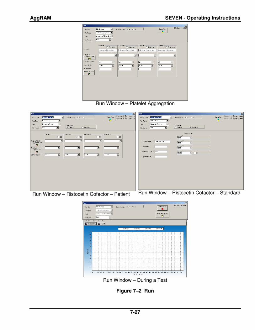
AggRAM SEVEN - Operating Instructions
7-27
Run Window – Platelet Aggregation
Run Window – Ristocetin Cofactor – Patient
Run Window – Ristocetin Cofactor – Standard
Run Window – During a Test
Figure 7–2 Run

AggRAM SEVEN - Operating Instructions
7-28
Figure 7–3 Patient Demographics Entry (List vs. Grid views)
Figure 7–4 Worklist Preparation
Figure 7–5 Steps

AggRAM SEVEN - Operating Instructions
7-29
Figure 7–6 View/Edit
Figure 7–7 Report Preview

AggRAM SEVEN - Operating Instructions
7-30
Figure 7–8 Demographics
Figure 7–9 Parameters
Figure 7–10 Standard Curve (Ristocetin)

AggRAM SEVEN - Operating Instructions
7-31
Figure 7–11 Levey–Jennings Chart
Figure 7–12 Westgard Failure Resolutions

AggRAM SEVEN - Operating Instructions
7-32
Figure 7–13 Archive

AggRAM EIGHT - Quality Control
8-1
Section 8 - Quality Control
The instrument automatically performs a self–test any time the power is turned on. Should an error message appear on the display, see section 10.2.
Each laboratory should establish its own normal range of expected values for the procedures in use. Refer to the package insert or assay sheet supplied with the reagents for further information. Consistent sample handling and procedural timing are essential for reproducibility and accuracy.
Each laboratory should also establish a quality control program that includes normal and abnormal controls to evaluate the instrument, reagent, and technologist performance. The quality control tests should be performed prior to performing each batch of tests on patient plasmas and with each change of personnel. Control data should be compared to the assay ranges printed on the assay sheet provided with the control. The patient data should be compared to the normal range values for the procedure in use and to the laboratory normal range values. Refer to the procedures supplied with the reagents for further information.
8.1. Daily Optical Calibration Check
Prior to the instrument's first daily use, the Optical Calibration Check must be performed, see section 10.1.1.
8.2. Ristocetin Cofactor QC
8.2.1. Setup QC
For instructions on QC parameter setup, see section 6.3.
8.2.2. Run QC
For instructions on running QC, see section 7.2.2.
8.2.3. View QC and QC Lot Change Over
For instructions on viewing the Levey–Jennings Chart QC and for changing over QC data, see section 7.7.11.
8.2.4. Westgard Rules
The software automatically keeps a record of control values from each run. Five Westgard Rules are included in the software to allow the laboratory to automatically monitor trends in QC data and to determine when QC data will no longer be accepted unless corrective action is taken. If the Westgard rules will not be used, QC data will be stored as usual; Levey–Jennings plots can be printed, but the laboratory must determine if QC data indicates a potential problem.
The Westgard rules used in the software are summarized below:
1–3s: A run will be rejected if one QC data point falls beyond the ± 3 SD range.
2–2s: A run will be rejected if two consecutive control values fall on the same side of the mean (are unipolar) and are greater than ± 2 SD units from the mean.
4–1s: A run will be rejected if four consecutive unipolar control values are greater than ± 1 SD from the mean.
r4s: A run will be rejected if the range between two consecutive bipolar values is greater than or equal to 4 SD units.
10x: A run will be rejected if ten consecutive data points fall on the same side of the mean.
One or more of these rules can be setup for use (section 6.3). If a control data point breaks a selected rule, the run may be accepted or rejected but the QC data is not used in the calculations determining mean and standard deviation. Once a rule has been broken, until an entry is made in the QC Westgard Resolution log (section 7.7.11), no additional QC data will be included in the Levey–Jennings results and any additional patient data will be stored with a W indicating an unresolved Westgard rule failure.

AggRAM NINE - Instrument Specifications
9-1
Section 9 - Instrument Specifications
Test Types: Platelet Aggregation and Ristocetin Cofactor
Charts: –20% to 110% activity (± 0.5%) versus time
Absorbance Range: 0.0 to 2.0 O.D.
Optical Chambers per module: Four chambers for combined or individual measurements
Cuvettes: 8 mm x 60 mm (silicone coated glass)
Stir Bars: 3.5 mm x 4 mm (coated magnet)
Measuring Wavelength: 650 nm
Module Input Power: 110/220 Vac, 50/60 Hz, 30 Watts Maximum
Incubation and Reaction Temperature: 37°C ± 1°C
Module Dimensions: < 6" (15.24 cm) Tall < 10" (25.40 cm) Wide < 17" (43.18 cm) Deep
Module Weight: < 15 lbs (6.75 kg)
Module will comply with:
• EN61010–2–101
• EN60601–1–2
• IEC 60825-1:2007
Software Operating System: Microsoft® Windows® 2000, Windows® XP, or Windows® 7
Instrument Operating Environment: Ambient Temperature Range 15° – 30°C (59 – 86°F) Humidity 10% – 80% (non–condensing)
Minimum Volume: 250 µL (with a stir bar)

AggRAM TEN - Maintenance, Troubleshooting, Warranty
10-1
Section 10 - Maintenance, Troubleshooting, Warranty
10.1. Maintenance
Each instrument is calibrated by Helena Laboratories during the manufacturing process. Customer calibration is required as specified in section 10.1.5. If during this calibration the instrument cannot be returned to acceptable ranges, any additional calibration must be performed by Helena Laboratories or their representatives.
This section describes routine operator maintenance procedures. For instrument calibration or for maintenance not described in this manual, call Helena Laboratories for assistance.
Table 10–1 Preventative Maintenance
Daily, If Used, Prior to First Use Perform Optical Calibration Check
Daily, If Used, End of the Day Clean Instrument
Clean Accessories
Weekly Clean Optical Wells
Monthly Adjust Scale Set
Check/Adjust Temperature Clean filter
10.1.1. Optical Calibration Check
Daily, or each time turned on, and prior to the first run, perform the Optical Calibration Check. Note that users with Run Only access cannot perform this check.
The intensity values obtained when performing the check should fall within a range of 0.145 to 0.217 and there should be less than a 10% difference between each value. Acceptable values are shown with a gray background color. Unacceptable values are shown with different background colors, each representing a type of failure, and a message displays attributing the background color to a specific failure.
To perform the Optical Calibration Check, use the following:
1. Beginning from the main menu, select File, Maintenance, and Optical Channel Check.
2. The Optical Calibration Check window (Figure 10–2) displays. Note that any previously obtained values have been removed.
3. Add 500 µL of distilled or deionized water to a clean cuvette. Handle the cuvette by the upper edges only to avoid fingerprints on the lower half of the cuvette where optical readings are taken.
4. Check the cuvette for bubbles and, if present, tap the cuvette to remove them. Remove the optics cover. Insert the cuvette into the first channel and press the channel button.
5. The channel indicator light turns red and green for 5 seconds followed by the intensity value for the Module and Channel tested displaying.
6. If the value is acceptable (displayed with a gray background), repeat steps 4 and 5 for each remaining channel (for all modules). If the value is not acceptable (displayed with a blue background color if low, pink if high, or yellow if the intra–channel results differ by more than 10%), see step 7.
7. If the values are not acceptable, select Re–Adjust Beams. Remove the cuvette(s) from the channel(s) and select OK in response to the prompt. Once the instrument finishes Adjusting beam strengths, repeat steps 4 and 5 for each channel with an unacceptable value.
8. If any value remains unacceptable, see section 10.2.
9. To obtain a printout of the values, select Print.
10. To exit, select the X located on the top right of the window.
11. Once all cuvettes have been removed, replace the optics cover.

AggRAM TEN - Maintenance, Troubleshooting, Warranty
10-2
10.1.2. Cleaning Instrument
After turning off the power and unplugging the power cord(s), clean spills with a cotton swab, soft cloth or sponge. Do not use corrosive or abrasive cleansers. Thoroughly dry before plugging in the power cord(s).
Should an instrument be contaminated by blood or blood derivative, spray any contaminated surface with a commercial virucidal and germicidal agent. Observe where the specimens are used inside the instrument and confine cleaning to that area. Wipe up the residue. These materials contain alcohol and alcohol is corrosive to metal surfaces.
10.1.3. Cleaning Accessories
Clean the stir bars, cuvette rack, and magnet retriever with disinfectant soap, water, and a soft brush (do not submerge the magnet retriever). Rinse thoroughly with deionized water. Dry thoroughly with lint–free tissues.
10.1.4. Cleaning Optical Wells
Optical chamber wells must be kept clean in order to obtain the most accurate absorbance readings. Always turn off the power and unplug the power cord(s) from the wall outlet, prior to performing the following:
1. Remove any cuvettes from the wells.
2. Use a cotton swab, dipped in alcohol, to rub the inside of the optical wells to remove any internal residue.
10.1.5. Scale Set
At initial installation and at least once per month, use Scale Set to calibrate the instrument. This must be done using Helena Scale Set Solution Catalog Number 1479 for Platelet Aggregation and Ristocetin Cofactor assays. If any value remains unacceptable after completing the steps included in section 10.2, Troubleshooting, any additional calibration must be performed by Helena Laboratories or their representatives. User IDs with Run Only access cannot perform this check.
1. The instrument must be allowed to warm up for at least 20 minutes before performing the scale set.
2. Allow the Scale Set Solutions to reach room temperature (15 to 30°C).
3. Beginning from the main menu, select File, Maintenance, and Scale Set.
4. The Scale Set window (Figure 10–3) displays.
5. Using the Scale Set #2 Value included on the procedure provided with the Scale Set Solutions, enter/alter the Scale Set Value using the keyboard.
6. Clear the currently displayed Scale Set data by selecting Start.
7. Prepare cuvettes with Scale Set #1 and #2 per the procedure provided with the Scale Set Solutions.
8. Remove the optics cover. Place the Scale Set #1 cuvette into the first channel and press the channel button. When the indicator light turns green and a value for Scale Set #1 displays for the Module and Channel tested, remove the cuvette.
9. Place the Scale Set #2 cuvette into the first channel and press the channel button. When the indicator light turns red and a value for Scale Set #2 displays for the Module and Channel tested, remove the cuvette.
10. Repeat steps 8 and 9 for each channel (for all modules).
11. Once both scale sets are run, the Result (V/O.D.) for each channel is calculated and displayed. V/O.D. represents the volts change per optical density between the two scale sets and is used to define the upper and lower optical density characteristics.
12. Acceptable V/O.D. values are shown with a gray background color. Any other background color signifies the value is unacceptable:
a. Blue indicates the value is too low.
b. Pink indicates the value is too high.

AggRAM TEN - Maintenance, Troubleshooting, Warranty
10-3
c. Yellow indicates the difference between scale set 1 and 2 for the same channel is >10%.
d. Orange indicates there is a difference >41% between the difference of scale set 1 and 2 for a channel versus the difference of scale set 1 and 2 for another channel.
13. If the results are acceptable, the instrument is ready for use. If results are unacceptable, repeat the entire Scale Set procedure.
14. If any value remains unacceptable, see section 10.2.
15. To obtain a printout of the scale set information, select Print. A printout of each scale set performed should be retained.
16. To exit, select X located on the top right of the window.
17. Once all cuvettes have been removed, replace the optics cover.
10.1.6. Adjust Temperature / Enter Module Parameters
Use the following steps as needed to review module information and/or monthly to check/adjust the module temperatures. Note that users with Run Only access cannot perform this check.
1. Beginning from the main menu, select File, Maintenance, and Enter Module Parameters.
2. The Module Parameter Entry window (Figure 10–4) displays.
3. For each module in use, a letter is displayed. Select the letter of the Module needed.
a. Module Serial Number displays the serial number of the selected module. This is preprogrammed information and cannot be altered.
b. Module Type indicates the selected module type as AggRAM. This is preprogrammed information and cannot be altered.
4. As needed, the Temperature Offset can be used to calibrate the optics/incubation block temperature. Note that during this process
the heater status should be alternating between Heater Regulation, Heater Off, and Heater On.
a. Place 500 µL of deionized water in a clean cuvette.
b. Remove the optics cover. Insert the cuvette into one of the channels of the selected module.
c. Allow the cuvette to equilibrate a minimum of 15 minutes.
d. Place a small temperature probe, with an accuracy at 37°C of +0.2°C, into the cuvette so that it contacts the bottom of the cuvette.
e. Allow the temperature probe to stabilize and note the temperature registered. The temperature should be 37°C ±1°C.
f. If the temperature is not 37°C ±1°C, enter/alter the Temperature Offset to adjust the temperature. Adjusting the Temperature Offset, either up or down, by 1 should result in a temperature change of 0.1°C and by 10 should result in a temperature change of 1.0°C. For example if the temperature reading is 39°, 2° high, and the current Temperature Offset is 10, then change the Temperature Offset by 20 to –10. Use either the slide bar or the keyboard to input the Temperature Offset. Allow the temperature to stabilize and re–measure the temperature. Repeat until the temperature is correct. Once the Temperature Offset is as needed, select Save to save the parameters displayed.
5. To obtain a printout of the selected module's parameter information, select Print.
6. To exit, select the X located on the top right of the window.
7. If the Temperature Offset was changed and saved, a prompt displays; select Yes to save the new offset number or No to exit the window without altering the number.
8. Once all cuvettes have been removed, replace the optics cover.

AggRAM TEN - Maintenance, Troubleshooting, Warranty
10-4
10.1.7. Cleaning Filter
One filter is located on the left side of each AggRAM module (Figure 5–2) and should be cleaned monthly. Always turn off the power and unplug the power cord(s) from the wall outlet, prior to performing the following:
1. Pull off the snap–on, filter cover and remove the filter.
2. Wash the filter in soap and water.
3. Rinse in water and air–dry the filter.
4. Replace the filter and cover.

AggRAM TEN - Maintenance, Troubleshooting, Warranty
10-5
Mo
nth
/Ye
ar:
__
__
__
__
___
__
__
__
___
___
__
__
___
__
_
Mo
dule
:__
___
__
Se
rial N
um
be
r:_
___
__
__
___
__
__
___
_
Mod
ule
:__
___
__ S
eri
al N
um
be
r:__
__
___
___
__
__
___
__
Ag
gR
AM
Pre
ve
nti
ve
Ma
inte
na
nc
e S
ch
ed
ule
3
1
Note
: D
uplic
ate
this
page f
or
main
tenance c
opie
s. Initia
l each ite
m a
s r
equired. R
efe
r to
section ten, M
ain
tenance, of th
e O
pera
tor's M
anual fo
r deta
ils. If you a
re
uncert
ain
about how
to p
erf
orm
any s
tep,
ple
ase c
onta
ct H
ele
na labora
tories E
lectr
onic
Custo
mer
Serv
ice D
ept. (
1–800–231–5663)
for
more
info
rmation. 3
0
29
28
27
26
25
24
23
22
21
20
19
18
17
16
15
14
13
12
11
10
9
8
7
6
5
4
3
2
1
Da
ily
Ite
ms
, If
Us
ed
Op
tical C
alib
ratio
n C
he
ck
Cle
an
In
str
um
en
t
Cle
an
Acce
sso
rie
s
Pla
ce
Op
tics C
ove
r
We
ek
ly I
tem
s
Cle
an
Op
tica
l W
ells
Mo
nth
ly I
tem
s
Ad
just
Sca
le S
et
Ch
eck/A
dju
st T
em
pe
ratu
re
Cle
an
Filt
er
Figure 10–1 Preventive Maintenance Checklist

AggRAM TEN - Maintenance, Troubleshooting, Warranty
10-6
Figure 10–2 Optical Calibration Check
Figure 10–3 Scale Set

AggRAM TEN - Maintenance, Troubleshooting, Warranty
10-7
Figure 10–4 Module Parameter Entry

AggRAM TEN - Maintenance, Troubleshooting, Warranty
10-8
10.2. Troubleshooting
If the recommended solutions should fail to solve a problem, call Helena Laboratories for assistance.
Table 10–2 Troubleshooting
Problem Possible Cause(s) Solution
No power to instrument Power cords unplugged Plug cords into properly grounded wall outlet.
Error message is displayed or error code appears
Error found during self–test or operation
Do as directed by the message or see Table 10–1. If message returns or an error code appears, call Helena Laboratories for assistance.
Temperature not at 37° C Temperature needs adjusting Adjust temperature (10.1.6).
Electrical problem Call Helena Laboratories.
Will not start run Power supply problem Call Helena Laboratories.
No power to incubator Electrical problem Call Helena Laboratories.
Incubator too hot Temperature needs adjusting Adjust temperature (10.1.6).
Electrical problem Call Helena Laboratories.
Fans do not run Electrical problem Call Helena Laboratories.
PRP too low PRP platelet level too low Check PRP specimen.
PPP level misadjusted Repeat procedure.
PRP too high PRP platelet level too high Dilute PRP with PPP.
PPP level misadjusted Repeat calibration (10.1.1) and re–measure.
No reaction occurs No stir bar in cuvette Repeat with stir bar in cuvette.
Reagent bad or in wrong concentration
Check reagent.
PRP specimen bad Obtain new specimen.
Stir motor(s) not running Check for stirring in each chamber. If no stirring, call Helena Laboratories for assistance.
Optical Channel / Calibration Check out of range
Lasers need adjusting Re–Adjust Beams (10.1.1).
Dirty optical wells Clean optical wells (10.1.4).
Call Helena Laboratories.
Bad aggregation / agglutination
No stir bar Re–measure with stir bar in cuvette.
PPP (100%) level misadjusted Repeat procedure.
Foreign matter in cuvette Repeat with clean cuvette.
Reagent or sample on side of cuvette due to pipetting
Repeat procedure.
Incorrect stir rate Check stirrer rpm, correct if needed.
Stir motor(s) not running Check for stirring in each chamber. If no stirring, call Helena Laboratories for assistance.

AggRAM TEN - Maintenance, Troubleshooting, Warranty
10-9
Problem Possible Cause(s) Solution
At power on, no response Not plugged in Check connections at both ends of power cord.
Electrical problem Call Helena Laboratories.
At power on printer is not ready
Printer power off Press power button on printer.
Printer off line Reset printer for use.
Loose interface cable or power cord
Check connections at both ends of cable and power cord.
Other Call Helena Laboratories.
Scale set digital values out of range
Bubbles formed in scale set solution
Remove cuvette and check for bubbles. Tap cuvette if bubbles are present and reread.
Scale set solutions bad Retry scale set adjustment using new solutions.
Blocked optics reading area Wipe cuvette clean with lint–free tissue, clean optical wells (10.1.4), and reread.
Lasers need readjusting Using Optical Calibration Check, readjust beams (10.1.1).
Call Helena Laboratories.
Setup and Maintenance unavailable for selection
Run Only operator ID in use Change operators (7.8.1).
Tests are in–process Wait until the run is complete or end the run.
Tests not aborted correctly Open the Run window, begin a run, and then select Abort Run.
No lines marking the slope Slope lines set to hide Show lines (7.7.2.1.1).
Slope is negative or zero Slope will display as N/A, edit slope to correct.
Table 10–3 Prompts and Error Messages
Message Possible Cause(s) Action Required
Access is denied – Com port X may be in use by another program
LIS is not available however is setup as an automatically used output device.
De–select the LIS as an auto output (6.7) and by–pass LIS locator (6.4). Can't perform this operation on a
closed port – Error attempting to Auto–Output data to LIS. DvcRunTypeBits=0x01
LIS port is specified to be COM X but was not able to detect an LIS there on power up and the LIS locater has not been bypassed.
Adding run for channel X to the Worklist Table because it is registered in the Run Table
A file previously restored was incomplete but is now correct.
No action required.
Number of modules in use has changed since worklist last used.

AggRAM TEN - Maintenance, Troubleshooting, Warranty
10-10
Message Possible Cause(s) Action Required
Get Activity – Error: Slope of Standard=0,00 for StdWrkLstNum=X
Deleted at least one of the points in the standard
Need min of at least 3 points for a curve
Illegal values: dvsr<=0 For Module x channel y 100% point=nnn <= baseline=mmm. Resetting channel
The test sequence for the test parameters may have the zero (PRP) and 100% (PPP) reversed.
Check, and correct as needed, the applicable test parameter’s test sequence (6.2.3)
During the run the PRP and PPP materials may have been reversed.
Repeat procedure.
Removing run for channel X from the Worklist Table because it is absent from the Run Table
Worklist selected for use which was previously used and aborted after at least one channel was complete and when prompted that data was deleted. The program corrected the discrepancy it found in the two synergetic files.
No action required.
Worklist altered and not re-saved.
Correct and save new worklist settings.
Slope Calculation Error: Invalid data for curve
Incorrect standard concentration(s) entered.
Review stand concentrations and, if incorrect, rerun standard.
TblPN error at column=X –– Rebuild "Display Parameter List" using Setup–>Test Parameters–>Select Display Parameters for Test=X 1 RunType=Patient
The display settings for the test are incorrect.
Reset and save the displays parameters for the test in question and then re–save that test’s settings (6.2).
TfmRun::UpdateDisplay Unable to LOCATE "TestTypeTag"="0" in TblTT
Corrupted database. Exit and restart the program. If the problem continues, call Helena Laboratories.
The HemoRam program was shutdown incorrectly last time it was run. There may have been some damage to the database as a result. The database is being repaired to ensure data integrity. (Startup was mm/dd/yyyy hh:mm:ss, Last good shutdown was )
Software was incorrectly closed/exited.
Proceed with opening and login to the software as usual and the database is repaired automatically. If desired, the database can be restored to one previously saved if the repairs is inadequate (7.8).
Unable to calculate slope (delta==0 which is the denominator for some parameters –– division by 0) (or npts<3 –– npts–2 is a denominator –– therefore division by 0)
A corrupted database was restored.
Repair database (7.8). If error continues, delete all patient curves associated with the standard.
WARNING: Stir motor(s) for channel(s): n of Module X stopped running during WrkLstNum=–nnnn."
Stir motor(s) stopped. Call Helena Laboratories.
Sensor failure.

AggRAM TEN - Maintenance, Troubleshooting, Warranty
10-11
10.3. Warranty
Helena Laboratories warrants its products to meet Helena’s published specifications and to be free from defects in materials and workmanship. Helena’s liability under this contract or otherwise shall be limited to replacement or refund of any amount not to exceed the purchase price attributable to the goods as to which such claim is made. These alternatives shall be the buyer’s exclusive remedies. In no case will Helena Laboratories be liable for consequential damages even if Helena has been advised as to the possibility of such damages.
The foregoing warranties are in lieu of all warranties expressed or implied, including, but not limited to, the implied warranties or merchantability and fitness for a particular purpose. In no event will Helena Laboratories be liable for indirect, incidental or consequential damages; the original user’s remedies being limited to repair or replacement at the manufacturer's option.
All software and driver disks provided with this instrument must be retained and be accessible in the sleeves provided at the end of this manual for the warranty to be valid.
Warranty Duration
This warranty is provided to the original purchaser for one year from date of sale.
Particular Exclusions
WARNING! Do not use the AggRAM for any purpose other than that described in this manual. Modification of the software or the use of the computer to run other programs may affect the operation and reliability of the instrument. Helena Laboratories is not liable for any consequential damages should the customer choose to ignore this warning.

AggRAM ELEVEN - Symbology
11-1
Section 11 - Symbology
NOTE: The following symbols may be used in this manual, or on the instrument, to provide information necessary to the user, if applicable.
Caution, electric shock hazard, high voltages capable of causing personal injury – shut down the instrument and unplug the power cord before touching – do not operate with the cover(s) removed
Caution, heat hazard – allow heated components to cool before handling
Caution, general hazard – see Precautions and Hazards (Sections 3 and 4) of Operator’s Manual before proceeding
Direct current
Alternating current
Both direct and alternating current
Ground (earth) terminal
Protective conductor terminal (grounded conductors)
Frame or chassis terminal
Equipotentiality (conductor with all parts at a single potential)
On (power switch)
Off (power switch)
Equipment protected throughout by double insulation or reinforced insulation (equivalent to Class II of IEC 536)
European authorized representative
Manufacturer
Indicates "do not place in trash" in countries or regions requiring recycling and other specific handling, such as in Europe, under the WEEE (Waste Electrical and Electronic Equipment) Directive, 2002/96/EC
Caution, laser hazard

AggRAM TWELVE - Communication Specifications
12-1
Section 12 - Communication Specifications
INTERFACE SPECIFICATIONS:
The HemoRAM software import/export interface conforms to the EIA standard RS–232C and is configured as a DTE (Data Terminal Equipment). Only receive data, transmit data and signal common lines are used. The baud rate is user selectable at 110, 300, 600, 1200, 2400, 4800, 9600, 14400, 19200, 28800, 38400, and 57600 baud. The number of data bits may be set at 7 or 8 and the number of stop bits may be 1 or 2. Parity may be set to none, even, or odd. Protocol options include no protocol, XON–XOFF flow control, or ASTM protocol.
MECHANICAL SPECIFICATIONS:
9 pin D–shell connector (male):
Pin Description 1 receive line detect 2 receive data* 3 transmit data* 4 data terminal ready 5 signal common* 6 data set ready 7 request to send 8 clear to send 9 ring indicator
*only these lines are used by the HemoRAM software.
COMMUNICATIONS PROTOCOL:
The protocol used by the HemoRAM software is user selectable (section 6.4). Listed below are the protocol options available.
No Protocol:
Data is transmitted and received as ASCII text with no flow control or error checking/ correction. This option is not recommended unless the HemoRAM software is to be connected to a terminal.
XON–XOFF Flow Control:
Data is transmitted and received as ASCII text and XON/XOFF (ASCII codes 17 and 19) handshaking is used to control data flow.
When exporting, the HemoRAM software will recognize an XOFF character and stop transmission until an XON character is received. There is no error checking or correction when using this protocol.
ASTM Protocol (E1381–95 and E1394–97):
This protocol provides procedures for link connection and release, delimiting and synchronism, sequence control, error detection and error correction. Data is transmitted and received as ASCII text and some restrictions are placed on which characters can be used in the data content. The restricted characters are: <SOH>, <STX>, <ETX>, <EOT>, <ENQ>, <ACK>, <DLE>, <NAK>, <SYN>, <ETB>, <LF>, <DC1>, <DC2>, <DC3>, and <DC4>.
There are three distinct phases in transferring information between the HemoRAM software and the computer system. In each phase, one system directs the operation and is responsible for continuity of the communication. The three phases assure the actions of sender and receiver are coordinated. The three phases are Establishment, Transfer, and Terminate.
Establishment Phase
The Establishment phase determines the direction of information flow and prepares the receiver to accept information. The sender notifies the receiver that information is available. The receiver responds that it is prepared to receive before information is transmitted. A system, which does not have information to send normally, monitors the data link to detect the establishment phase. It acts as a receiver, waiting for the other system.
The system with information available initiates the establishment phase. After the sender determines the data link is in a neutral state, it transmits the <ENQ> character to the intended receiver. Upon receiving the <ENQ>, the receiver prepares to receive information. All other characters are ignored. It replies with the <ACK> character to signify

AggRAM TWELVE - Communication Specifications
12-2
it is ready. With this sequence of events, the establishment phase ends and the transfer phase begins.
A receiver that cannot immediately receive information replies with the <NAK> character. Upon receiving the <NAK>, the sender must wait at least 10 seconds before transmitting another <ENQ>.
Should both systems simultaneously transmit an <ENQ>, the data link is in contention. The HemoRAM software has priority to transmit information when contention occurs. Contention is resolved as follows. Upon receiving a reply of <ENQ> to its transmitted <ENQ>, the computer system must stop trying to transmit; it must prepare to receive. When the next <ENQ> is received, it replies with an <ACK> or <NAK> depending on its readiness to receive.
Transfer Phase
During the transfer phase, the sender transmits information to the receiver. The transfer phase continues until all information has been sent.
Information is sent in frames, each frame contains a maximum of 247 characters (including frame overhead). Records or data that are longer than 240 characters are divided between two or more frames. A frame is one of two types, an intermediate frame or an end frame.
Intermediate frames terminate with the characters <ETB>, checksum, <CR> and <LF>. End frames terminate with the characters <ETX>, checksum, <CR> and <LF>. The frame structure is illustrated below:
Intermediate Frame: <STX> FN "data" <ETB> C1 C2 <CR> <LF>
End Frame: <STX> FN "data" <ETX> C1 C2 <CR> <LF>
Where: <STX> – Start of text transmission character FN – single digit frame number "0" to "7" "data" – data content
C1 – first character of checksum "0" – "9" & "A" – "F" C2 – second character of checksum "0" – "9" & "A" – "F" <ETB> – end of transmission block character <ETX> – end of text transmission character <CR> – carriage return character <LF> – line feed character
The frame number is an ASCII digit ranging from "0" to "7". The frame number begins at "1" with the first frame of the transfer phase. The frame number is incremented by one for each new frame transmitted. After "7", the frame number rolls over to "0".
The checksum permits the receiver to detect a defective frame. The checksum is encoded as two characters, which are sent after the <ETB>, or <ETX> character. The checksum is computed by adding the binary values of the frame characters, keeping the least significant eight bits of the result. The checksum is transmitted as ASCII hexadecimal.
The checksum is initialized to zero with the <STX> character. The first character used in computing the checksum is the frame number. Each character in the data is added to the checksum (modulo 256). The computation for the checksum does not include <STX>, the checksum characters, or the trailing <CR> and <LF>.
After the frame is sent, the sender stops transmitting until a reply is received. The receiver replies to each frame. A reply of <ACK> signifies the last frame was received successfully and the receiver is prepared to receive another frame.
A reply of <NAK> signifies the last frame was not received successfully; the receiver is prepared to receive the frame again. Upon receiving the <NAK>, the sender retransmits the last frame with the same frame number. In this way, transmission errors are detected and automatically corrected. A frame is not successfully received if any of the following occur:

AggRAM TWELVE - Communication Specifications
12-3
1 – any character errors are detected (parity error, framing error, etc.)
2 – the frame checksum doesn't match the checksum computed on the received frame.
3 – the frame number is not the same as the last accepted frame or one higher (modulo 8).
A frame may be retransmitted up to 6 times. If after 6 tries the frame has still not been successfully transmitted, the sender transmits an <EOT> and regards the data link to be in the neutral state.
A reply of <EOT> signifies the last frame was received successfully, the receiver is ready to receive another frame, but is a request to the sender to stop transmitting. The sender does not have to stop transmitting after receiving the request. If it continues to transmit, there is a possibility of overflowing the receiver's buffers. If the sender chooses to ignore the <EOT>, the receiver must retransmit the request.
Termination Phase
The termination phase returns the data link to the clear or neutral state. The sender notifies the receiver that all data has been sent.
The sender transmits the <EOT> character and then regards the data link to be in a neutral state. Upon receiving the <EOT>, the receiver also regards the data link to be in the neutral state.
Timeouts
The sender and receiver both use timers to detect loss of coordination between them. The timers provide a method for recovery if the communication line or the other device fails to respond.
During the establishment phase, the sender sets a timer when transmitting the <ENQ>. If a reply of an <ACK>, <NAK> or <ENQ> is not received within 15 seconds, a timeout occurs and the sender regards the link to be in the neutral state.
During the establishment phase, if the computer (as receiver) detects contention, it
sets a timer. If an <ENQ> is not received within 20 seconds, a timeout occurs and the receiver regards the link to be in the neutral state.
During the transfer phase, the sender sets a timer when transmitting the last character of a frame. If a reply is not received within 15 seconds, a timeout occurs. After a timeout, the sender aborts transmission by proceeding to the termination phase.
During the transfer phase, the receiver sets a timer when first entering the transfer phase or when replying to a frame. If a frame or <EOT> is not received within 30 seconds, a timeout occurs. After a timeout, the receiver discards the last incomplete record or set of data and regards the link to be in the neutral state.
DATA TRANSFER FORMAT
The HemoRAM software in general adheres to the ASTM Standard Specification for Transferring Information Between Clinical Instruments and Computer System. The exceptions concern sending a QC record.
General Information
Data is exchanged in records of different types. Each record is introduced by field number 1 identifying the record type, and terminated by a carriage return. There are 5 record types used by the HemoRAM software: Header Record (H), Patient Record (P), Test Order Record (O), Result Record (R), and the Terminator Record (L).
Records are related to each other in a definite hierarchy. At level zero is the Header record and Terminator record. At level one is the Patient record and the Request–Information record. At level two is the Test Order record. At level three is the Result record.
A sequence of patient records, order records, or result records at one level is terminated by the appearance of a record type of the same or higher level. Thus, a sequence of results for one patient is terminated by the next patient record.

AggRAM TWELVE - Communication Specifications
12-4
Each record is composed of fields, which are position sensitive and variable in length. Each field is separated by a field delimiter (e.g., the vertical bar, "|"). The position sensitivity requires that when the contents of a field are null, its corresponding field delimiter must be included in the record to ensure that the i'th field can be found by counting (i–1) delimiters. Delimiters are not included for trailing null fields; that is, if the tenth field was the last containing data, the record could terminate after the tenth field (with a carriage return) and therefore would contain only nine delimiters.
A system may transmit a null value for a field because (1) it does not know the value, (2) it knows the value is irrelevant to the receiving system, or (3) the value has not changed since the last transmission, or any combination thereof. Because the sending system can use null values to indicate no change, a null value does not overwrite existing data in the receiving system. The transmission of a double quote (ASCII 34) in a field tells the receiving system to replace any existing value with a null value.
Each field may be composed of sub–components. These sub–components are separated by a component delimiter (e.g., the caret, "^"). The component delimiter is used to separate data elements of fields of a hierarchical or qualifier nature.
Header Record
The header record must always be the first record in a transmission. When the HemoRAM software transmits a header record, it will have the following format:
H|\^&|||Helena Laboratories^HemoRAM^n.n .n.nn^Sns|||||||P|1394–97|yyyymmddhhmmss
If the message is being sent for a QC rather than any other RunType, then the header will be as follows:
H|\^&|||Helena Laboratories^HemoRAM^n.n .n.nn^Sns|||||||Q|1394–97|yyyymmddhhmmss
with a Q in the Processing ID field instead of a P.
n.n.n.nn – HemoRAM software version number
Sns – Serial numbers of each attached module, starting with Module A, separated by spaces
yyyymmddhhmmss – 4–digit year, 2–digit month, 2–digit day, 2–digit hour, 2–digit min., 2–digit seconds.
Patient Record
A patient record is not included when sending QC data.
EXAMPLE: P|1||12|||||F||||||||0|0|
Order Record
The HemoRAM software will transmit an order record immediately preceding any results records for a patient as required in the ASTM specification. The format will be as follows: O|1||CrvSeqNum|UniversalTestID|||||| |||||<CR>
CrvSeqNum – A sequential test number (up to 4 billion) in the fourth field (Instrument specimen ID).
UniversalTestID – (see section below on the Universal Test ID) All components of the Universal Test ID must be sent except the ID of the Result (and since there may be several parameters sent as results, they would be sent in the Result Record instead).
EXAMPLE:
For a patient: O|1||7|^^^Platelet Aggregation ^*Screen1^Collagen^Patient^104551188|||||||||||||||||||||F
For a QC: O|1||123|^^^Ristocetin ^Ristocetin ^Ristocetin^QC^2035301–2^1^SomeStandard ^99.9
For a standard: O|1||3333|^^^Ristocetin^ Ristocetin^Ristocetin^Standard^1353424–2^^ ThisStd^97.5^25

AggRAM TWELVE - Communication Specifications
12-5
The HemoRAM software currently does not recognize test order records transmitted by the computer system.
Result Record
Each parameter will be transmitted as a separate result record.
For patient results, if test range limits have been entered (currently not available), they will be included in the sixth (reference ranges) field.
The ninth (result status) field always shows "F" for Final results or is left blank.
A result will be transmitted in the following format:
R|n|UniversalTestID|nnnn|unit of measure| nnnn–nnnn|||||F|||date/timestarted|date/time completed<CR>
n – Sequence number.
UniversalTestID – (see section below on the Universal Test ID) Any information sent as part of the Order record may be omitted by using just a series of component delimiters. Since everything but the ID of the result itself is sent during the Order record, only the Result ID is necessary here.
Any components in the UniversalTest ID for the Result Record which are duplicates of the Order record may be omitted.
nnnn – result
nnnn–nnnn – User defined reference range.
date/time started – Date and time the test was started (yyyymmddhhmmss). The date is transmitted with the year first, month second and day last.
date/time completed – Date and time the test finished
EXAMPLE:
For patient result record: R|1|^^^^^^^^^^^^^ PRP|1.39|µg/ml||||F||Eric|20020503143809|20020503144028|
For QC result record: R|1|^^^^^^^^^^^50^ FinalActivity|13.80|%||||F|||20020502094336|20020502094546|
For a standard result record: R|1|^^^^^^^^^^ ^^Activity|66.4|%||||F|||20050502082335|20050502094546|
Terminator Record
The terminator record must be the last record in a transmission. When the HemoRAM software transmits a terminator record it will have the following format: L|1|N<CR>
Universal Test ID
The UniversalTestID is made up of a series of component fields separated by component delimiters. The UniversalTestID is included in both the Order Record and the Result Record. Several components are only pertinent to the Result Record and would therefore not be included when sending the Order Record. The complete list (including those for both Order and Result Records) follows:
Universal Test ID – Left blank (unused part of ASTM spec)
Universal Test ID Name – Left blank (unused part of ASTM spec)
Universal Test ID Type – Left blank (unused part of ASTM spec)
TestType – The Test Type for the current channel being sent.
MainTest – The test or screen for the module(s) run.
SpecificTest – The test (reagent or assay) for the current channel being sent.
RunType – The Run Type (Patient, Reference, Standard, or QC) for the current channel being sent.
LotNumber – The Lot number of the reagent used during the run.
QCLvl – If for a QC then this is the QC level, otherwise it is left blank or zero.

AggRAM TWELVE - Communication Specifications
12-6
StdRefID – For a standard or any run referencing a standard, this is the ID of that standard. For a reference, this is the ID of that reference.
RefLvl – If this run references a standard, then this is the Reference level associated with that standard.
Conc – If this is a standard then Conc is the concentration of the dilution for this run.
Units – Units for the Concentrations.
ResultID – The name of the parameter being reported in the current result record. These result parameters are listed below. The first six parameters are sent for all tests and RunTypes:
InitialMax (PPP), InitialMin (PRP), MaxPCPoint (Max % Point), MaxPCTime (Time associated with Max % Point), Slope, and LagTime.
SDI (Standard Deviation Index) is sent if the RunType is a QC.
Activity and FinalActivity are sent if the TestType is Ristocetin.
Slope2 and/or AreaUnderCurve (Area Under the Curve in %) are sent if they are selected on the Test Parameters setup menu.

AggRAM THIRTEEN - Reports
13-1
Section 13 - Reports
The following is a list of possible symbols used on reports and their meanings:
1. L – indicates the PRP O.D. is out of range, less than 0.2, implying low platelet count or that calibration may be off.
2. H – indicates the PRP O.D. is out of range, greater than 1.2, implying high platelet count or that calibration may be off.
3. M – with slope data, indicates the slope has been manually edited.
4. M – with QC data, indicates the QC was manually entered.
5. r – correlation coefficient
6. # – indicates the slope is out of range, either the patient or QC slope is lower than the lowest or higher than the highest slope measured for the standard.
7. W – indicates an unresolved Westgard failure occurred during or prior to the run.
8. N/A – indicates the slope is less than or equal to zero.

AggRAM THIRTEEN - Reports
13-2
Figure 13–1 Platelet Aggregation Patient Bottom Chart

AggRAM THIRTEEN - Reports
13-3
Figure 13–2 Platelet Aggregation Patient Mid Chart

AggRAM THIRTEEN - Reports
13-4
Figure 13–3 Platelet Aggregation Patient Top Chart

AggRAM THIRTEEN - Reports
13-5
Figure 13–4 Ristocetin Cofactor Patient Top Chart
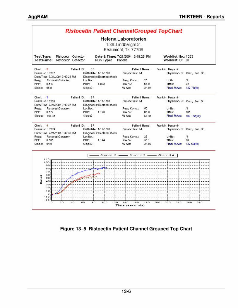
AggRAM THIRTEEN - Reports
13-6
Figure 13–5 Ristocetin Patient Channel Grouped Top Chart

AggRAM THIRTEEN - Reports
13-7
Figure 13–6 Ristocetin Cofactor Patient Mid Chart

AggRAM THIRTEEN - Reports
13-8
Figure 13–7 Ristocetin Cofactor Patient Bottom Chart

AggRAM THIRTEEN - Reports
13-9
Figure 13–8 Ristocetin Standard – QC Bottom Chart

AggRAM THIRTEEN - Reports
13-10
Figure 13–9 Ristocetin Standard – QC Top Chart

AggRAM THIRTEEN - Reports
13-11
Figure 13–10 Ristocetin Standard – Patients - QC Top Chart

AggRAM THIRTEEN - Reports
13-12
Figure 13–11 Ristocetin Standard – Patients - QC Bottom Chart

AggRAM THIRTEEN - Reports
13-13
Figure 13–12 QC Levey-Jennings

AggRAM THIRTEEN - Reports
13-14
Figure 13–13 QC Summary

AggRAM FOURTEEN - Index
14-1
A
abort, 7-1, 7-3, 7-5, 7-10 absorbance, 1-1, 2-1, 9-1, 10-
2 access level, 6-1, 6-7, 7-1, 7-
24 agglutination, 2-1, 2-2 aggregation, 1-1, 2-1, 2-2, 3-
1, 7-2, 7-3, 7-4, 7-5, 7-11, 7-13
archive, 6-9, 7-15, 7-22 area under curve, 6-3, 6-4 assigned, 6-6 asterisk, 6-3 ASTM, 6-7, 12-1, 12-3, 12-4 auto import, 6-7 auto-output, 6-8
B
baseline, 2-1, 7-2 baud rate, 6-7, 12-1 begin run, 7-1, 7-3, 7-5, 7-9 blank, 7-2, 7-3, 7-4, 7-5, 7-11 block temperature, 6-3, 6-4,
10-3
C
calibration, 2-2, 7-18, 10-1, 13-1
channels, 6-3, 6-4, 7-16 chart, 7-17 cleaning, 3-1, 4-1, 10-2, 10-4 comments, 7-14 composite, 7-16 computer, 2-1, 2-2, 5-2, 5-3,
6-1, 6-7, 7-1, 10-13, 12-1, 12-2, 12-3, 12-5
concentration, 2-1, 6-3, 6-4 controls, 6-3, 7-2, 7-4, 8-1 correlation coefficient, 13-1 cuvette, 2-2, 6-5, 7-1, 7-2, 7-
3, 7-4, 7-5, 9-1, 10-1, 10-2, 10-3
D
data bits, 6-7, 12-1 date, 7-15, 7-22
delete, 6-3, 6-4, 6-7, 6-9, 7-6, 7-8, 7-15, 7-18, 7-20, 7-21, 7-22
demographics, 7-6, 7-17 determination time, 6-5 display parameters, 6-3, 6-4,
6-5, 7-17
E
edit, 6-4, 7-10, 7-11, 7-12, 7-13, 7-14, 7-18, 13-1
error messages, 7-24 exit, 6-3, 6-4, 6-5, 6-6, 6-7, 6-
8, 6-9, 7-6, 7-7, 7-8, 7-9, 7-13, 7-14, 7-18, 7-19, 7-20, 7-22, 7-23, 7-24, 10-1, 10-3
export, 6-7, 7-12, 12-1 external computer, 2-1, 2-2,
6-7
F
file utilities, 6-9, 7-15, 7-22 filter, 10-4
H
help, 7-25 HemoRAM software, 5-3, 6-1,
7-1, 12-1, 12-2, 12-3, 12-4, 12-5
I
import, 6-7, 7-6, 12-1 import/export parameters, 6-7 incubate, 2-1, 7-2, 7-3, 7-5 installation, 5-1 installation verification report,
5-4
L
Levey-Jennings Chart, 7-20, 8-1
limit days, 7-19 login, 5-3, 6-1, 7-1, 7-24 log-log, 6-4, 7-20 lot-to-date, 6-6, 7-21 lyophilized platelets, 2-1
M
M (manually modified), 7-13 maintenance, 10-1, 10-2, 10-
3 manual slope, 7-13 mean calculation method, 6-
6, 7-21 measurement, 2-1, 2-2 micro volumes, 6-2, 6-3, 7-1,
7-2, 7-4 module, 1-1, 2-2, 5-2, 5-3, 5-
4, 6-1, 6-3, 6-4, 7-1, 7-3, 7-4, 7-5, 7-9, 9-1, 10-1, 10-2, 10-3, 10-4
monitor, 5-3, 6-1, 7-1 month-to-date, 6-6, 7-21
N
new standard, 7-4
O
optical calibration check, 10-1 optical chambers, 2-2, 9-1,
10-2 optics cover, 5-2, 7-1, 7-3, 7-
4, 10-1, 10-3 overlay, 7-7, 7-19 overlay reference, 7-19
P
pan, 7-22 parity, 6-7, 12-1 password, 6-1, 6-7, 7-1, 7-24 patient, 2-1, 2-2, 6-3, 6-5, 7-2,
7-4, 7-6, 7-7, 7-8, 7-14, 7-15, 7-17, 7-18, 7-19, 8-1, 12-4, 12-5, 13-1
patient demographic name & date entry syntax checking, 6-1, 7-6
patient demographics, 6-1, 7-6
pipette, 7-1, 7-2, 7-3, 7-4, 7-5 platelet aggregation, 1-1, 2-1,
6-2, 7-1, 7-2, 7-6, 7-7, 7-11, 7-13, 7-19, 9-1
platelet count, 3-1, 7-18, 13-1 platelet solution, 7-11

AggRAM FOURTEEN - Index
14-2
PPP, 2-1, 2-2, 7-1, 7-2, 7-3, 7-4, 7-5, 7-11
printer, 5-2, 5-3, 6-1, 7-1, 7-10, 7-24
printer driver, 5-4 printout, 10-1, 10-3 protocol, 6-7, 12-1 PRP, 2-1, 3-1, 7-1, 7-2, 7-4,
7-5, 7-11, 7-18, 13-1
Q
QC, 6-5, 6-6, 7-4, 7-6, 7-8, 7-9, 7-12, 7-14, 7-18, 7-19, 7-20, 7-21, 7-22, 8-1, 13-1
QC parameters, 6-6, 6-7 quality control, 7-8, 8-1
R
raw data, 7-12 reagent, 1-1, 2-1, 2-2, 6-2, 6-
3, 6-4, 6-5, 6-6, 7-1, 7-2, 7-3, 7-4, 7-5, 7-7, 7-11, 7-25, 8-1
Reagent, 7-19 reference, 2-2, 7-7, 7-9, 7-19 report, 6-8, 7-12, 7-18, 7-20,
7-21, 7-22, 13-1 select location(s) for report
to appear, 6-8 setup, 6-8
report parameters, 6-8 results, 2-1, 2-2, 6-6, 7-2, 7-4,
7-6, 7-9, 7-10, 7-11, 7-13, 7-19, 7-25, 10-1, 10-3, 12-5
ristocetin cofactor, 2-1, 6-3, 6-6, 7-2, 7-4, 7-7, 7-8, 7-11, 7-12, 7-13, 7-14, 7-19, 7-20, 9-1
run, 7-1, 7-2, 7-3, 7-4, 7-5, 7-6, 7-9
RunType, 6-5, 6-9, 7-3, 7-4, 7-8, 7-9, 7-14, 7-19
S
sample, 2-1, 2-2, 7-2, 7-4, 7-5, 7-11, 8-1
scale set, 10-2, 10-3 search, 7-14 semi-log, 6-4, 7-20 setup, 6-1, 6-2, 6-3, 6-4, 6-5,
6-6, 6-7, 6-8, 7-6, 7-7, 7-8, 7-24
single channel, 7-14, 7-16 slope, 2-2, 7-12, 7-13, 7-14,
7-18, 7-19, 13-1 slope II, 6-3, 6-4 slope location, 7-13 slope window, 7-13 smooth, 7-10, 7-14 software, 6-7, 7-13, 7-15, 7-
20, 7-24, 7-25, 8-1, 9-1, 10-13, 12-1, 12-3, 12-4 serial number, 7-25 version, 7-25
spills, 10-2 standard, 2-1, 2-2, 6-3, 6-5, 7-
3, 7-8, 7-9, 7-18, 7-19, 7-20, 8-1, 13-1
standard curve, 6-4, 7-2, 7-4, 7-12, 7-13, 7-14, 7-19
standard volumes, 6-2, 6-3, 7-1, 7-2, 7-4
step identification, 6-5 step time, 6-5, 7-11 steps, 7-1, 7-2, 7-3, 7-4, 7-5,
7-9, 7-10, 7-11 stir bar, 7-2, 7-3, 7-5, 9-1, 10-
2 stir speed, 6-3, 6-4, 7-7, 7-8,
7-9 stop, 7-11 stop bits, 6-7, 12-1
T
temperature, 5-2, 6-3, 6-4, 7-9, 9-1, 10-2, 10-3
test, 2-1, 2-2, 6-2, 6-3, 6-4, 6-9, 7-2, 7-3, 7-4, 7-5, 7-7, 7-8, 7-9, 7-10, 7-11, 7-20, 7-22, 8-1, 9-1
test parameters, 6-2, 6-4, 6-5, 7-10
test sequence, 6-3, 6-4, 6-5 test setting, 6-3 test settings, 6-4 TestType, 6-2, 6-4, 6-5, 6-6,
7-7, 7-8, 7-9, 7-14, 7-19, 7-22
time, 2-1, 2-2, 6-5, 7-2, 7-3, 7-5, 7-11, 7-13, 7-15, 7-22, 9-1
U
unit of measure, 6-3, 6-4, 7-7, 7-11
user ID, 6-1, 6-7, 7-1, 7-24 utilities, 6-9, 7-15, 7-22
V
view, 6-4, 7-10, 7-11, 7-14, 7-16, 7-17, 7-19, 7-22, 7-24, 7-25
volume, 6-2, 6-3, 6-5, 7-1, 7-11, 7-25, 9-1
von Willebrand, 2-1
W
warranty, 10-13 wavelength, 9-1 Westgard, 6-6, 7-4, 7-6, 7-18,
7-21, 7-22, 8-1, 13-1 window seconds, 6-3, 6-4 worklist, 7-1, 7-2, 7-3, 7-4, 7-
5, 7-6, 7-7, 7-8, 7-9, 7-14, 7-15, 7-16, 7-18, 7-19, 7-20
Z
zoom, 7-22

©November 2013 D6500094D Helena Laboratories 11/13
AggRAM
System
Catalog Number 1484 and 1487
Software Version 1.3
Operator’s Manual
For additional information, call Helena Laboratories toll free at 1–800–231–5663.
Helena Laboratories Helena Laboratories UK, Ltd.,
P.O. Box 752 Queensway South,
Beaumont, TX 77704-0752 Team Valley Trading Estate,
USA Gateshead, Tyne and Wear,
United Kingdom NE11 0SD