d8 advance pre-installation guide doc-m88-zxx146...
TRANSCRIPT
XRDthink forward
Bruker AXS GmbH
D8 ADVANCE
Pre-Installation GuideEnglish

The reproduction, transmission or use of this document or its contents is not permitted without express written authority. Offenders will be liable for damages. All rights reserved.
We have checked the contents of this manual for agreement with the hardware and software described. Since deviations cannot be precluded entirely, we cannot guarantee full agreement. However, the data in this manual are reviewed regularly and any necessary corrections are included in subsequent editions. Suggestions for improvement are welcome.
All configurations and specifications are subject to change without notice.
Order no. DOC-M88-ZXX146 V1. Update: June 17, 2009.
© 2009 Bruker AXS GmbH, Karlsruhe, Germany.
All trademarks and registered trademarks are the sole property of their respective owners.
Printed in the Federal Republic of Germany.
Bruker AXS GmbHÖstliche Rheinbrückenstr. 4976187 Karlsruhe, GermanyTel. +49 (7 21) 5 95-28 88Fax +49 (7 21) 5 95-45 [email protected]
D8 ADVANCE Pre-Installation Guide Table of Contents
DOC-M88-ZXX146 V1 – 06.2009 i
D8 ADVANCE Pre-Installation Guide
Table of Contents
Room Planning ..........................................................................................................1 Area of Installation..........................................................................................................................1 Transport and Dimensions.............................................................................................................1
Heat Dissipation.........................................................................................................................7 Pre-Installation ................................................................................................................................8
Mains Connection and Earthing.................................................................................................8 Service via Internet ..................................................................................................................13 Cooling-Water Supply ..............................................................................................................14 General Notes for the Use of Göbel Mirrors ............................................................................16
Safety Guidelines and Technical Specifications ..................................................17 Safety Guidelines ..........................................................................................................................17
About This Manual ...................................................................................................................17 General Safety Precautions .....................................................................................................19 Warnings and Symbols ............................................................................................................24
Symbols ............................................................................................................................24 Illuminated Warning Displays ...........................................................................................26
System Control..............................................................................................................................27 System Status and Control Buttons.........................................................................................27 System Power Control .............................................................................................................29 Enclosure Control Buttons .......................................................................................................32 Illumination - Button .................................................................................................................32 Open Door - Button..................................................................................................................32 Screen Keys – Status Display and High Voltage Operation....................................................33
Table of Contents D8 ADVANCE Pre-Installation Guide
ii DOC-M88-ZXX146 V1 – 06.2009
Upper Screen Key (X-ray Generator Status and Control) ................................................34 Lower Screen Key (System Status)..................................................................................36
Power Supply of Accessory Components................................................................................38 Location of instrumentation inside diffractometer housing.....................................................38
Location of components in diffractometer................................................................................38 Lower Front Side......................................................................................................................39 Lower Left Side ........................................................................................................................40 Lower Rear Side ......................................................................................................................41 Lower Right Side......................................................................................................................42 Starting the Instrument.............................................................................................................43 Powering Down the Instrument................................................................................................44 Starting the Software ...............................................................................................................45
Protection against Radiation .......................................................................................................46 General Remarks.....................................................................................................................46 Special Service Operation Modes............................................................................................49 Tube Housing...........................................................................................................................50 X-ray Safety Circuits ................................................................................................................51 Control of the X-ray Shutter .....................................................................................................53 Shutter Warning Displays ........................................................................................................54 Tube mount interlock ...............................................................................................................54 Resetting the X-ray Safety System..........................................................................................54
Machinery Safety...........................................................................................................................55 Maintenance of the Diffraction System.......................................................................................58
Servicing Precautions ..............................................................................................................58 Cleaning the Diffraction System...............................................................................................58 Maintenance of the Diffractometer Measuring Equipment ......................................................59
Goniometer .......................................................................................................................59 Sample Changer...............................................................................................................59
Maintenance of the Optional Internal Cooling Unit (A14-A6) ...................................................60 Checking the Ion Exchanger....................................................................................................60 Checking the Cooling Water Level...........................................................................................60 Refilling the Cooling Water Tank .............................................................................................60
Technical Specifications ..............................................................................................................64 General Diffraction System......................................................................................................64 Electrical Specifications ...........................................................................................................67 Diffraction Components ...........................................................................................................68

D8 ADVANCE Pre-Installation Guide Room Planning
DOC-M88-ZXX146 V1 – 06.2009 1
Room Planning
Careful room planning and the completed pre-installation are prerequisites for rapid final assembly and commissioning of the D8 X-ray diffractometer by a Bruker AXS specialist. Room planning and pre-installation should be carried out with the assistance of the appropriate Bruker AXS office after suit-able consultation.
Area of Installation The installation of the devices must be planned such that the diffractometer is accessible from all sides and that the cooling air can flow without restrictions. A minimum of 70 cm free space must be provided behind the diffractometer and on both sides.
The floor should be level and with a sufficient supporting capacity.
Avoid direct solar radiation.
To avoid heat near the diffractometer, the external cooling-water unit, if provided, should be installed in a separate room.
If the external cooling-water unit is installed in a closed room, make sure that the waste heat is carried off and fresh air is supplied.
Transport and Dimensions The system is equipped with integrated casters for easier transportation inside the laboratory. Side, back, and front panels can be removed for moving the system through doors. The enclosure may be detached from the base cabinet for transport. The enclosure and base cabinet are connected both mechanically (screws) and electrically. Both electrical and mechanical connections must be separated before attempting to detach the enclosure and base cabinet.

Room Planning D8 ADVANCE Pre-Installation Guide
2 DOC-M88-ZXX146 V1 – 06.2009

D8 ADVANCE Pre-Installation Guide Room Planning
DOC-M88-ZXX146 V1 – 06.2009 3
Fig. 1: Outside dimension of installed system.

Room Planning D8 ADVANCE Pre-Installation Guide
4 DOC-M88-ZXX146 V1 – 06.2009

D8 ADVANCE Pre-Installation Guide Room Planning
DOC-M88-ZXX146 V1 – 06.2009 5
Fig. 2: Inside dimension of radiation safety enclosure.

Room Planning D8 ADVANCE Pre-Installation Guide
6 DOC-M88-ZXX146 V1 – 06.2009

D8 ADVANCE Pre-Installation Guide Room Planning
DOC-M88-ZXX146 V1 – 06.2009 7
Fig. 3: Transport dimension.
Heat Dissipation If necessary, the waste heat of the D8 ADVANCE must be removed from the room by a ventilation or air conditioning system.
The maximum heat dissipation from the diffractometer (including measuring and control electronics and X-ray generator) to the air is 1 kW.

Room Planning D8 ADVANCE Pre-Installation Guide
8 DOC-M88-ZXX146 V1 – 06.2009
Pre-Installation
Mains Connection and Earthing The D8 diffraction system can be connected to almost all common AC power networks worldwide that provide the required power.
The systems will be delivered factory pre-set for the nominal mains supply voltages listed in table.
Table 1: Electrical requirements (including X-ray generator and control electronics but without acces-sories)
Mains supply Technical Data
Mains supply voltage Standard: On request:
Three phases supply: 3 x 120 VAC (+/- 10%) 3 x 230 VAC (+/- 10%) 3 x 240 VAC (+6%/- 10%) One phase supply: 200 VAC (+/- 10%) 208 VAC (+/- 10%) 230 VAC (+/- 10%) 240 VAC (+6%/-10%)
Frequency range 47-63 Hz
Maximum power consumption Diffractometer system with internal water cooling unit (A14-A1)Diffractometer system without internal water cooling unit
max. 6.5 kVA max. 6.0 kVA
Surge voltage category according to IEC 664 II
NOTE
The power consumption of the optional external water cooling unit is not included in Table 1. (Refer to the technical specifications of the specific device being installed on your site.)

D8 ADVANCE Pre-Installation Guide Room Planning
DOC-M88-ZXX146 V1 – 06.2009 9
By default the diffractometer system contains a 10 m long 5 x 6 mm2 power cable (5-core, 6 mm2 area each) for connection to a three-phase AC network. That cable can be connected either directly to the switchboard of the in-house mains system or it can be equipped with an approved plug connector (shrouded plug and socket outlet to DIN 49462, VDE 0623, IEC 309-1).
The electrical connection of the instrument to the in-house network must be provided via fuses or automatic circuit breakers for all phases. It must be possible to disconnect the diffraction system com-pletely from the power supply using either a labeled switch or a labeled automatic circuit breaker, which is located nearby the diffraction system.
WARNING
In some specific local mains networks the so-called „neutral“ power line (marked with „N“) is not con-nected to earth potential. In this case the neutral power line N and the three phases L1, L2 and L3 must be controlled by a four-phase automatic circuit breaker. In case of an error on either the neutral power line N or on one of the phases L1, L2 or L3 that circuit breaker must disconnect all power lines (i.e. N, L1, L2 and L3) from the mains network. (Please refer to your local regulations.)
Fig. 4, Fig. 5, Fig. 6, and Fig. 7 show how to implement the mains connection.
As an option a residual current circuit breaker can be added. It must be rated for a maximum current of 3 x 32 A or 3 x 40 A. It must have a fault current of 30 mA.
The host computer will be powered directly from the in-house mains system.
If necessary the computer must be connected to the mains via an interference filter.

Room Planning D8 ADVANCE Pre-Installation Guide
10 DOC-M88-ZXX146 V1 – 06.2009
Fig. 4: Mains connection – three phases supply 120/208 VAC (50/60 Hz).

D8 ADVANCE Pre-Installation Guide Room Planning
DOC-M88-ZXX146 V1 – 06.2009 11
Fig. 5: Mains connection – Three phases supply 220/380VAC (50/60Hz), 230/400VAC (50/60 Hz) and 240/415 VAC (50/60 Hz).

Room Planning D8 ADVANCE Pre-Installation Guide
12 DOC-M88-ZXX146 V1 – 06.2009
Fig. 6: Mains connection - one phase supply 200VAC (50/60Hz) , 208 VAC (50/60 Hz).

D8 ADVANCE Pre-Installation Guide Room Planning
DOC-M88-ZXX146 V1 – 06.2009 13
Fig. 7: Mains connection - one phase supply 220VAC (50/60 Hz), 230VAC(50/60 Hz) and 240VAC (50/60 Hz).
Service via Internet The D8 diffractometer can be connected to internet. This allows remote operation and servicing of the instrument.

Room Planning D8 ADVANCE Pre-Installation Guide
14 DOC-M88-ZXX146 V1 – 06.2009
Cooling-Water Supply In order to supply the X-ray generator with the required cooling water, a connection must be realized to a main water supply with a pressure-free discharge.
* Wasserfilter C71127-Z482-E4, 1¼"-Innengewinde beidseitig, Maschenweite 0,15 mm * Water filter C71127-Z482-E4, 1¼"-female thread, on both sides, mesh size 0.15 mm (100 mesh) * Filtre à eau C71127-Z482-E4, pas de vis interne de 1¼" de chaque coté, largeur des mailles 0,15 mm
Fig. 8: Cooling water supply.
The D8 diffractometer is equipped with cooling-water hoses (2 x 10 m, NW 1/2“, with screw connec-tions for the D8 Diffractometer system).
Depending on humidity and room temperature, the cooling-water temperature should be sufficiently high to avoid condensation. For example, assuming a relative humidity of 80% and a room tempera-ture of 30 °C the dew point is 26 °C; at a room temperature of 25 °C the dew point is 21 °C, respec-
D8 ADVANCE Pre-Installation Guide Room Planning
DOC-M88-ZXX146 V1 – 06.2009 15
tively. If the head of the tube housing has a temperature equal to or less than the dew point, then con-densation will occur.
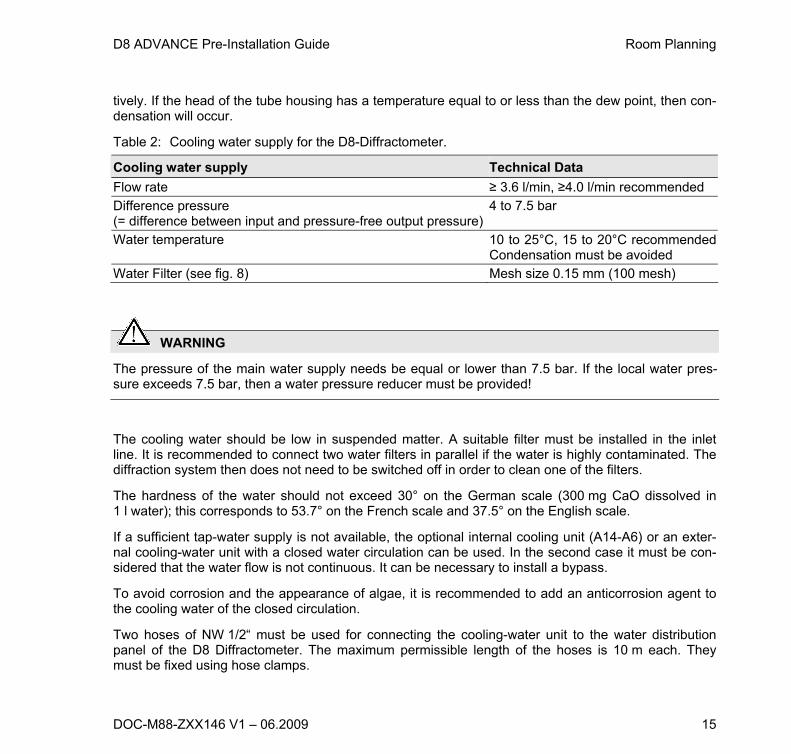
Table 2: Cooling water supply for the D8-Diffractometer.
Cooling water supply Technical Data
Flow rate ≥ 3.6 l/min, ≥4.0 l/min recommended
Difference pressure (= difference between input and pressure-free output pressure)
4 to 7.5 bar
Water temperature 10 to 25°C, 15 to 20°C recommendedCondensation must be avoided
Water Filter (see fig. 8) Mesh size 0.15 mm (100 mesh)
WARNING
The pressure of the main water supply needs be equal or lower than 7.5 bar. If the local water pres-sure exceeds 7.5 bar, then a water pressure reducer must be provided!
The cooling water should be low in suspended matter. A suitable filter must be installed in the inlet line. It is recommended to connect two water filters in parallel if the water is highly contaminated. The diffraction system then does not need to be switched off in order to clean one of the filters.
The hardness of the water should not exceed 30° on the German scale (300 mg CaO dissolved in 1 l water); this corresponds to 53.7° on the French scale and 37.5° on the English scale.
If a sufficient tap-water supply is not available, the optional internal cooling unit (A14-A6) or an exter-nal cooling-water unit with a closed water circulation can be used. In the second case it must be con-sidered that the water flow is not continuous. It can be necessary to install a bypass.
To avoid corrosion and the appearance of algae, it is recommended to add an anticorrosion agent to the cooling water of the closed circulation.
Two hoses of NW 1/2“ must be used for connecting the cooling-water unit to the water distribution panel of the D8 Diffractometer. The maximum permissible length of the hoses is 10 m each. They must be fixed using hose clamps.

Room Planning D8 ADVANCE Pre-Installation Guide
16 DOC-M88-ZXX146 V1 – 06.2009
3/4“ piping of copper or galvanized steel must be used in the case of larger distances. The maximum length is 15 m per pipe. The ends must be provided with hose unions. Short hoses NW 1/2” are used to connect the X-ray generator and the cooling-water unit. The maximum permissible difference in height between the cooling-water unit and the X-ray generator is 6 m.
General Notes for the Use of Göbel Mirrors All different versions of the Göbel mirrors are high-precision optical devices which are exposed to harmful environmental conditions. The generation of ozone by the X-ray beam in the vicinity of the mirrors surface can activate chemical reactions of molecules present in the ambient air. The end prod-ucts of these reactions might result in contamination of the surface of the mirror. Therefore, clean laboratory conditions and prevention of water condensation at the head of the X-ray tube and the Göbel mirror housing are highly recommended. Please, maintain the temperature of the cooling water high enough to avoid condensation. Avoid continuous water flow while the generator power is switched off.
Despite taking precautions, it may still be necessary to periodically clean the surface of the Göbel mirror. In this case, please contact Bruker AXS for support.

D8 ADVANCE Pre-Installation Guide Safety Guidelines and Technical Specifications
DOC-M88-ZXX146 V1 – 06.2009 17
Safety Guidelines and Technical Specifications
Safety Guidelines
About This Manual This manual contains information and guidelines, which should be observed to ensure personal safety, as well as to protect the product. These notices are highlighted in this manual by the warning symbols and are marked as follows according to the level of danger.
DANGER
The word ‘Danger’ indicates that death, severe personal injury or substantial property damage will result if proper precautions are not taken.
WARNING
The word ‘Warning’ indicates that personal injury or significant property damage will result if proper precautions are not taken.
CAUTION
The word ‘Caution’ indicates that minor personal injury or property damage can result if proper precau-tions are not taken.

Safety Guidelines and Technical Specifications D8 ADVANCE Pre-Installation Guide
18 DOC-M88-ZXX146 V1 – 06.2009
NOTE
The word ‘Note’ draws your attention to particularly important information on the product, handling the product, or to a particular part of the documentation.
Qualified Personnel The D8 diffraction system or its parts shall only be set up and operated in conjunction with this man-ual. Only qualified personnel should be allowed to work on this equipment.
The primary installation, maintenance and repair of the diffraction system shall be carried out only by personnel who are authorized by Bruker AXS.
All repairs, adjustments and alignments performed at any components of the diffraction system (incl. host computer) must be carried out strictly in accordance with the established safety practices and standards of the country where the equipment is installed.
Correct Usage This device and its components shall only be used for the applications described in the catalogue or the technical description, and only in connection with devices or components from other manufactur-ers which have been approved or recommended by Bruker AXS.
This product can only function correctly and safely if it is transported, stored, set up, and installed cor-rectly, and operated and maintained as recommended by Bruker AXS.
Disclaimer and Liability We have checked the contents of this manual for agreement with the hardware, Instrument Control Software and software described. Since deviations cannot be precluded entirely, we cannot guarantee full agreement. However, the data in this manual are reviewed regularly and any necessary correc-tions will be included in subsequent editions. Suggestions for improvements are welcome.

D8 ADVANCE Pre-Installation Guide Safety Guidelines and Technical Specifications
DOC-M88-ZXX146 V1 – 06.2009 19
General Safety Precautions
Danger of X-ray Radiation
The D8 diffraction system is an analytical instrument with a strong X-ray source. Shielding and safety
equipment guarantee that the emitted radiation does not exceed 1 µSv/h
H *(10) during operation.
Bruker AXS screens the emitted X-ray radiation of each single D8 diffractometer prior to delivery under worst case conditions. The D8 diffractometer is in compliance with the requirements for X-ray systems which are certified as complete protection instrument (“Vollschutzgerät”) according to the German X-ray safety standards called “Röntgenverordnung”. The D8 is also compliant with the French radiation safety standard AFNOR NFC 74-100.
The enclosure of the diffraction experiment serves as the radiation safety box. It must always be en-sured that the enclosure and the setup of the goniometer correspond to one of the specified configura-tions and that the safety system is always in operation. Read chapter ‘Protection Against Radiation’ before turning on the diffraction system.
If it seems that the safety system does not work correctly or the radiation protection is impaired due to any reason, you must switch off the system immediately and contact your local Bruker AXS Service representative.
Manipulations and modifications of the safety systems are strictly forbidden!
DANGER: X-ray Radiation
The enclosure of the diffraction experiment serves as the X-ray radiation safety box. If the front doors,which are made of a radiation protection glass, are damaged by any reason you must immediately switch off the diffractometer system. Contact your local Bruker AXS Service representative.

Safety Guidelines and Technical Specifications D8 ADVANCE Pre-Installation Guide
20 DOC-M88-ZXX146 V1 – 06.2009
DANGER: High Voltage
Inside the D8 diffraction system voltages up to 60 kV DC are generated. High voltages are present in the high-voltage generator, in the X-ray tube as well as in the connecting high-voltage cable. In addi-tion, the various X-ray detectors are operated with high-voltages up to 5 kV DC, the VÅNTEC-1 up to 15 kV DC.
Inside the VÅNTEC-1, voltages up to 15 kV DC occur which are not accessible from the outside. High voltages exist inside the detector and in the cables with label HV connecting the detecting unit and the control rack. After turning off the system, high voltages are still present. They discharge over time. Therefore, wait a few minutes before removing cables from the controller unit.
In case one of these high-voltage components is damaged, please switch off the system immediately and contact your local Bruker AXS service office.
DANGER: High Voltage
The D8 diffraction system must be operated only with the mains supply voltages that are listed on the type plate mounted on the lower left front side of the system.
The system’s mains distribution unit is located behind the left side panel of the diffraction system. Typi-cally, the mains distribution unit will be accessed by authorized service persons only. Some of the optional components of the diffraction system receive their electrical power from the switched power sockets which are part of the mains distribution unit. If the power line of such a component needs to be connected or removed the left side panel can be opened by the user.
Be aware! When the equipment is connected to the mains supply, some terminals of the mains distri-bution unit may be live. Therefore, it is absolutely necessary to switch off the external mains supply before opening the side panel. It is not sufficient to just press the D8’s ‘Stand-by ’ button. The mains supply must be switched off externally on the user’s side (wall socket or external switch) or the mains disconnector switch of the system. (See chapter ‘Control Electronics - Mains Distribution Board’ in the User’s Manual.) After the side panel is attached again it must be securely fixed using the provided screws.

D8 ADVANCE Pre-Installation Guide Safety Guidelines and Technical Specifications
DOC-M88-ZXX146 V1 – 06.2009 21
DANGER: Injury!
The rear panel of the radiation safety enclosure is designed for radiation shielding and is extremely heavy. The rear panel is mainly removed for easier transport and during first installation of system. Removal is not necessary for standard use and service.
Be aware that the components attached to the goniometer will move during operation. During the nor-mal operation mode these components are covered by the radiation enclosure completely. As soon as the front doors are opened all mechanical drives will stop immediately. But, in alignment and servicing mode the various drives are accessible from the front or the back side and may move even if the front doors or the back panel are removed.
DANGER
Some of the mechanical drives are very powerful and can cause severe personal injury!
WARNING
Before making substantial changes in mechanical set up (heavy parts or parts with class B drives like the goniometer, the power of the diffraction system must be turned off completely using the ‘Power off’ button.
WARNING
In order to prevent substantial damages in the system you must turn off the power of the diffraction system completely before connecting or disconnecting any cables attached to the X-ray tube, the ra-diation detectors, motors or to the various accessory components.

Safety Guidelines and Technical Specifications D8 ADVANCE Pre-Installation Guide
22 DOC-M88-ZXX146 V1 – 06.2009
WARNING: LED light!
The interior of the enclosure is illuminated by LED lights located on the ceiling.
It is a class 1 LED product. Do not stare into beam
WARNING: Analyzing toxic substances!
When analyzing toxic substances follow the legal national safety regulations.
Only use sample holders which are recommended by Bruker AXS for the respective analyzing meas-urement.
WARNING: Change of instrument’s location!
The location of the D8 system shall only be changed by staff authorized and trained by Bruker AXS.
All documentation (manuals, radiation and other safety certificates ...) must be moved together with the instrument.
WARNING: Disposal of instrument!
Follow all valid national regulations for disposal and contact Bruker AXS. Instrument contains Beryl-lium (X-ray tube and detector) and batteries (some electronic boards).
D8 ADVANCE Pre-Installation Guide Safety Guidelines and Technical Specifications
DOC-M88-ZXX146 V1 – 06.2009 23
WARNING: Beryllium!
Do not touch the front window of X-ray detectors, the X-ray tube and sealed optics like some Göbel mirrors as they contain Beryllium. Fumes or dust from Beryllium and its compounds can be hazardous if inhaled! During use, corrosion of beryllium may occur. Beryllium must not be cut, machined or handled in any way. Beryllium metal in solid form, as contained in our products, presents no special health risk.
Disposal of parts containing beryllium must comply with all applicable national regulations.
WARNING: Battery!
Some of the electronic boards are equipped with batteries. Disposal of batteries must comply with all applicable national regulations.
WARNING
Sometimes complex D8 systems will be supplied by several power supply lines. The system and its components will be live until all power lines connected to the system are disconnected from the mains power supply.
WARNING: Analyzing biological active substances!
When analyzing biologic active substances follow applicable national safety regulations and IEC 61010-2-081.

Safety Guidelines and Technical Specifications D8 ADVANCE Pre-Installation Guide
24 DOC-M88-ZXX146 V1 – 06.2009
CAUTION
Proper lifting VÅNTEC-1
Installation of the VÅNTEC-1 detector requires lifting of components that weigh up to 43 lbs (19.5 kg).Whenever possible, two or more people should lift objects together. Use proper lifting techniques at all times. Use the following steps as an overview of proper lifting techniques.
1. Plan: practice the lift. While lifting, bend at the knees, keep your back straight, tighten your stomach and lift with your legs.
2. Position: keep your body close to the object you wish to lift—your stability increases the closer you are to the object. Keep your feet shoulder width apart.
3. Movement: avoid making awkward movements while holding a heavy object. Get help if the object is too heavy or cumbersome.
Warnings and Symbols The following indicators and symbols are displayed on the D8 Diffraction System. Strictly obey all instruc-tions and warning text printed on the labels which are attached to the various parts of the equipment.
Symbols
Radiation Danger!
This symbol and a label "X-rays ON" are fixed on each of the four orange warning displays.
Radiation Danger!

D8 ADVANCE Pre-Installation Guide Safety Guidelines and Technical Specifications
DOC-M88-ZXX146 V1 – 06.2009 25
Live Part! Risk of Electric Shock!
Caution! Read the Operating Instructions!
Protective Ground/Earth Terminal
Follow all valid national regulations for disposal
Danger of Injury! Danger of Crushing!
Danger of biological active substances!
Equipment that can be potentially infectious due to the samples or reagents used.

Safety Guidelines and Technical Specifications D8 ADVANCE Pre-Installation Guide
26 DOC-M88-ZXX146 V1 – 06.2009
Illuminated Warning Displays
Enclosure:
‘X-rays On’ Radiation Danger!
The illuminated orange warning displays on the right and left side ofthe enclosure and on the tube housing indicate that the high voltagegenerator is turned on and the X-ray tube is operating.
Tube housing:
The yellow warning display located at the tube housing indicates thathigh voltage is applied to the X-ray tube.
‘Shutter Open’: Radiation Danger! The red warning display located at the tube housing indicates that theshutter is open; X-ray radiation is emitted towards the sample.
For detailed information see section “Protection against Radiation” page 46.

D8 ADVANCE Pre-Installation Guide Safety Guidelines and Technical Specifications
DOC-M88-ZXX146 V1 – 06.2009 27
System Control
System Status and Control Buttons
The status and control buttons of the D8 ADVANCE are located at different points on the front and on the left side of the instrument.
X-ray generator status and con-trol screen-key and system status display
Door open and interior illumina-tion switches
Emergency switch-off buttons
Instrument power on-off switches, mains disconnector switch

Safety Guidelines and Technical Specifications D8 ADVANCE Pre-Installation Guide
28 DOC-M88-ZXX146 V1 – 06.2009
NOTE
Devices connected to AC outlets X101 and X102 will be switched off by the mains diconnector switch.
The AC outlets X102 which are located on the mains distribution panel will be turned off by the Instru-ment Power Off button (Stand-by ) and also by the Emergency Switch Off button.
The AC outlets X101 which are located on the mains distribution panel will not be turned off by the Instrument Power Off button (Stand-by ) and also not by the Emergency Switch Off button.
Fig. 9: System can be secured against unauthorized use by safety lock. Switch On of system is impossible when locked. All internal lines other than those marked by orange isolation are cut from electrical power supply. Generation of X-rays is impossible when system is locked.

D8 ADVANCE Pre-Installation Guide Safety Guidelines and Technical Specifications
DOC-M88-ZXX146 V1 – 06.2009 29
System Power Control
The system-wide power control elements are located in the lower part of the instrument. Two emer-gency switch off buttons on the left and right side and a power control panel on the left side.
emergency switch off button (left side)
Instrument Power On
mains disconnector switch (lock-able)
Instrument power off (Stand-by )

Safety Guidelines and Technical Specifications D8 ADVANCE Pre-Installation Guide
30 DOC-M88-ZXX146 V1 – 06.2009
Emergency Switch Off
If pressed, it switches off the control electronics, the high voltage generator and all components connected to the AC outlets X102 located on the mains distribution unit. The X-ray source is turned off and all moving drives will stop instantly. Com-ponents connected to AC outlet X101 are not switched off.The stop button should only be used in emergency situations and not for normal shut-down of the diffractometer system!
Instrument Power On
Green Switch with an “I”. Powers up the instrument. After the boot procedure the instrument is ready for operation.
This button switches on the control electronics, the high voltage generator and all components connected to the AC outlets X102 located on the mains distribution unit.
As soon as the system is ready the Generator Symbol goes to the white “I” if no error is pending (otherwise the error will be shown) and the System Display will change to blank white if no error is pending (otherwise, the error is displayed). Now, the high voltage generator can be activated by pressing the X-ray Generator Screen key Unit on the left side.
Instrument Power Off (stand-by )
Red Switch with a “Stand-by ”. Powers down the Instrument, the X-ray Generator and all drives will stop immediately. Special components (if installed) like vacuum pumps might remain powered on if they are connected to X101. Components connected to X102 are switched off.
Mains discon-nector switch
This Switch can completely cut all power supply and disables all electrical compo-nents that are connected over the main power distribution of the instrument. This switch can be locked with a safety lock Fig. 9 to prevent an illegal switching on of an instrument. Set this switch to 0 before unplugging the main power connector.

D8 ADVANCE Pre-Installation Guide Safety Guidelines and Technical Specifications
DOC-M88-ZXX146 V1 – 06.2009 31
NOTE
Do not press the power off button as long as the X-ray generator generates X-rays, i.e. as long as the orange X-RAY ON displays are illuminated. This could reduce the lifetime of the X-ray tube and the high voltage generator significantly.
Before switching off the diffraction system it is recommended to reduce the high voltage and current of the generator to lowest values (e.g. 20kV/5mA) using the control software (e.g. XRD Commander), first. Then turn off the high voltage generation by switching off the X-ray Generator. The X-RAY ON displays will be turned off at once. After that the instrument can be switched off by pressing the In-strument Power Off Button.

Safety Guidelines and Technical Specifications D8 ADVANCE Pre-Installation Guide
32 DOC-M88-ZXX146 V1 – 06.2009
Enclosure Control Buttons
For the instrument X-ray enclosure, two switches directly control the illumination and the door lock mechanism.
Illumination - Button This button switches the illumination within the enclosure on and off. This also works if the in-strument is powered down to stand-by . During boot-up of the instrument the illumination is switched off. After booting the illumination bright-ness is determined by the door status (opened or closed). By default the brightness is reduced when the door is closed and increased if the door is open. Changes to that can be made in the Config. If the Instrument is powered down, only on and off is possible over this switch, no bright-ness control is possible.
Open Door - Button Under normal operational conditions the door handles are locked by a mechanical shutter. To open the front door this button must be pressed. Then the front doors can be opened. If the "Open Door" Button is activated while the tube window is open the X-ray shutter will close automatically. After closing the front doors the X-ray shutter can be opened again. Alternatively the Enclosure Object of the Instrument Control Software allows unlocking the door via Software.

D8 ADVANCE Pre-Installation Guide Safety Guidelines and Technical Specifications
DOC-M88-ZXX146 V1 – 06.2009 33
Screen Keys – Status Display and High Voltage Operation
The system has two Screen Key Units on the left side.
The upper Unit is used for The High Voltage control; the Lower is used for System Status Information and has currently no function when pressing it.
X-ray Generator Switch
System Status

Safety Guidelines and Technical Specifications D8 ADVANCE Pre-Installation Guide
34 DOC-M88-ZXX146 V1 – 06.2009
Upper Screen Key (X-ray Generator Status and Control)
White blank Display Shown during startup sequence of the Instrument
Switch On Symbol Shown when the X-ray generator is switched off and is ready to be switched on.Press the symbol once to start up the X-ray generation.
Heating On Blinking yellow when the generators tube heating is enabled and no X-rays arebeing generated. Constant yellow when the switch off circuit has been closed, but X-rays are notbeing generated. Press once to switch off the generator.
X-rays On, Generator is busy Shown when the X-rays are switched on and the generator is ramping its power(yellow background). Press once to switch off the generator.
X-rays On, Generator ready Shown when the Generator has reached its set values (Yellow Background) Press once to switch off the Generator.
X-ray Safety Circuit Error The X-ray generator will be switched off if a safety error occurred. For details lookinto the safety board in the diagnostic plug-in”Tools”, which can be found withinthe Bruker AXS measurement suite. If the error is repaired, the symbol will disappear and the switch on symbol willappear (if no subsequent error is pending)

D8 ADVANCE Pre-Installation Guide Safety Guidelines and Technical Specifications
DOC-M88-ZXX146 V1 – 06.2009 35
White Blinking
Safety warning is present. See detailed info in TOOLS. Switch on is not possible ifthis symbol is active.
Generator Error Either the generator or one of its connected components (tube, safety circuit, andwater cooling system) has an error. For details look into the X-ray generator inTools (plug-in Bruker AXS measurement suite). If the error is repaired, the symbol will disappear and the “switch On” symbol willappear (if no subsequent error is pending)
Water Cooling System Error The water cooling system switched off the generator because of an error in thecooling system. For a detailed error message, look into the water cooling unit inTools (plug-in Bruker AXS measurement suite) If the error is repaired, the symbol will disappear and the switch on symbol willappear (if no subsequent error is pending)
Conditioning Enabled When this symbol blinks in blue, the Tube Conditioning is enabled. To abort thisaction, press the button once, the Generator will switch off. Then you are able toproceed operation in normal mode. It is not recommended to abort tube conditioning, since this process helps to es-tabish a longer lifetime of the tube.

Safety Guidelines and Technical Specifications D8 ADVANCE Pre-Installation Guide
36 DOC-M88-ZXX146 V1 – 06.2009
Lower Screen Key (System Status)
White blinking blank Display The Instrument is booting
White blank Display The Instrument has booted and is ready for operation
Green blank Display The Instrument is controlled by a client (e.g. Measurement Server)
Measurement running This symbol is shown blue flashing if a measurement is in progress
Door open The front door is open. A measurement is only possible with closed doors
Sample Changer Error The built-in sample changer has an error and needs a user interaction beforeproceeding (for more detailed description of the pending error and repairing seeTools)
Detector error At least one Detector has an error.
Drive collision At least two drives are collided. For repairing see Tools
Drive error At least one drive has an error. For repairing see Tools

D8 ADVANCE Pre-Installation Guide Safety Guidelines and Technical Specifications
DOC-M88-ZXX146 V1 – 06.2009 37
NOTE
Pending system alarms or warnings (red display elements) will be usually indicated as written informa-tion by the application software on the computer screen. In addition, the diagnostic plug-in “Tools” can be used to get a complete diagnosis of any present alarms or warnings. Also, repairing is possible with help of this program.
Safety Guidelines and Technical Specifications D8 ADVANCE Pre-Installation Guide
38 DOC-M88-ZXX146 V1 – 06.2009
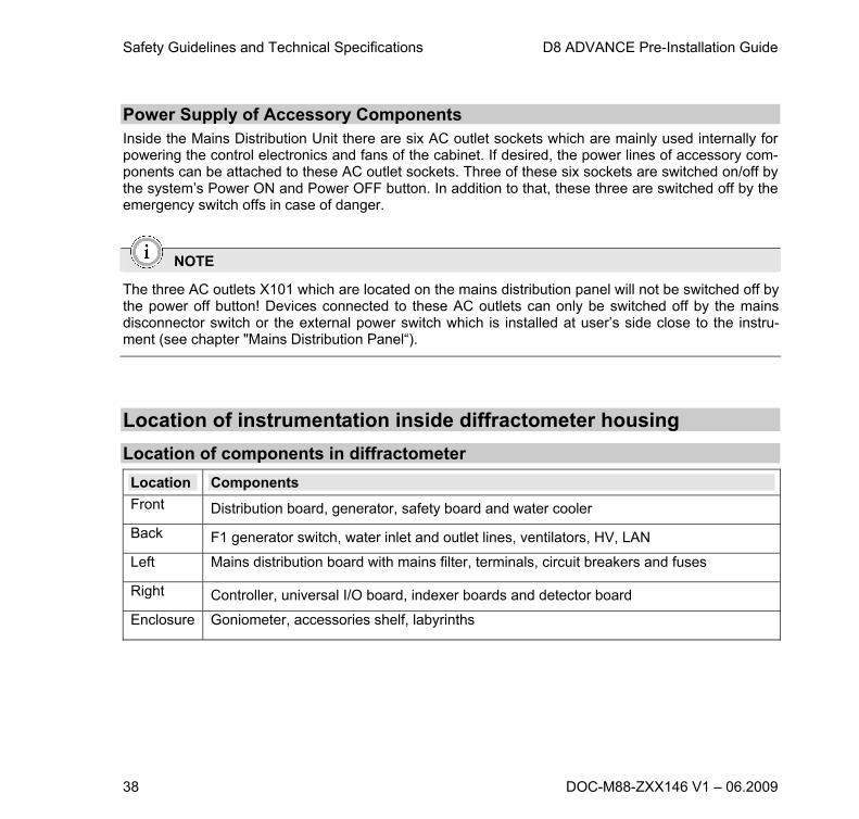
Power Supply of Accessory Components Inside the Mains Distribution Unit there are six AC outlet sockets which are mainly used internally for powering the control electronics and fans of the cabinet. If desired, the power lines of accessory com-ponents can be attached to these AC outlet sockets. Three of these six sockets are switched on/off by the system’s Power ON and Power OFF button. In addition to that, these three are switched off by the emergency switch offs in case of danger.
NOTE
The three AC outlets X101 which are located on the mains distribution panel will not be switched off by the power off button! Devices connected to these AC outlets can only be switched off by the mains disconnector switch or the external power switch which is installed at user’s side close to the instru-ment (see chapter "Mains Distribution Panel“).
Location of instrumentation inside diffractometer housing
Location of components in diffractometer
Location Components
Front Distribution board, generator, safety board and water cooler
Back F1 generator switch, water inlet and outlet lines, ventilators, HV, LAN
Left Mains distribution board with mains filter, terminals, circuit breakers and fuses
Right Controller, universal I/O board, indexer boards and detector board
Enclosure Goniometer, accessories shelf, labyrinths

D8 ADVANCE Pre-Installation Guide Safety Guidelines and Technical Specifications
DOC-M88-ZXX146 V1 – 06.2009 39
Lower Front Side At the lower front side of the diffractometer the following components are located:
Distribution board, generator, safety board, and water cooler.
A metal rack to the left accommodates the generator and the water cooler as slide-in units. On either side of this rack are three extra height units that can be used to accommodate additional slide-in units.
To the right of the rack are located the distribution and safety boards.
Fig. 10: Lower front side of instrument.
Distribution board Generator Safety board Water cooler
Safety Guidelines and Technical Specifications D8 ADVANCE Pre-Installation Guide
40 DOC-M88-ZXX146 V1 – 06.2009
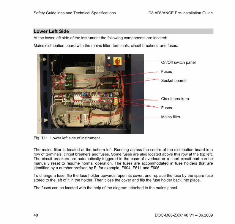
Lower Left Side At the lower left side of the instrument the following components are located:
Mains distribution board with the mains filter, terminals, circuit breakers, and fuses.
Fig. 11: Lower left side of instrument.
The mains filter is located at the bottom left. Running across the centre of the distribution board is a row of terminals, circuit breakers and fuses. Some fuses are also located above this row at the top left. The circuit breakers are automatically triggered in the case of overload or a short circuit and can be manually reset to resume normal operation. The fuses are accommodated in fuse holders that are identified by a number prefixed by F, for example, F604, F611 and F606.
To change a fuse, flip the fuse holder upwards, open its cover, and replace the fuse by the spare fuse stored to the left of it in the holder. Then close the cover and flip the fuse holder back into place.
The fuses can be located with the help of the diagram attached to the mains panel.
On/Off switch panel Fuses Socket boards Circuit breakers Fuses Mains filter

D8 ADVANCE Pre-Installation Guide Safety Guidelines and Technical Specifications
DOC-M88-ZXX146 V1 – 06.2009 41
Two black socket boards are located to the right and above the row of terminals, circuit breakers and fuses (regulate the flow of current to the various components). Depending on the electrical state of the instrument, these socket boards can be supplied or not supplied with power. The power supply is con-trolled by the power-on and power-off switches and the mains disconnector switch, which can be ac-cessed from the outside of the instrument.
The instrument has three electrical states:
Electrical states
State
Power-up Button
Power-down Button
Mains discon-nector switch
Upper Socket Board X101
Lower Socket Board X102
On On Off On Supplied with power
Supplied with power
Stand-by
Off Off On No power Supplied with power
Off Off Off Off No power No power
Lower Rear Side At the lower rear side of the instrument the following components are located:
F1 generator switch, water inlet and outlet lines, and ventilators.
The F1 generator switch is located at the rear of the generator. This switch is actuated in case of a malfunction and interrupts the flow of high-voltage current to the generator. It can be reset manually.
Openings are provided in the rear panel for two water lines (inlet and outlet) and a power supply line for the generator.
Two ventilators are housed in the rear panel and are connected to the instrument by a power line.

Safety Guidelines and Technical Specifications D8 ADVANCE Pre-Installation Guide
42 DOC-M88-ZXX146 V1 – 06.2009
Lower Right Side At the lower right side of the instrument the following components are located:
Control rack, universal I/O board, indexer boards, detector board.
Fig. 12: Lower right side of instrument.
The control rack accommodates the detector board, which controls the detector; the universal I/O board; and 2 indexer boards, which control up to 2 and 4 axes, respectively. Attached to the control rack at the top right is the Ethernet switch, which connects the instrument to the control PC, or option-ally to the network (LAN).
In the 19” frame accommodating the control rack are four extra height units which can be used to ac-commodate additional components. In the instrument shown in Fig. 12 above, three of these height units are occupied by a controller.
Inside the control rack itself are also several slots free which might be used for additional boards. As shown, these must be covered by blind flanges if not used.
Control rack Ethernet switch 2 indexer boards Universal I/O board (with plugs) Detector board
D8 ADVANCE Pre-Installation Guide Safety Guidelines and Technical Specifications
DOC-M88-ZXX146 V1 – 06.2009 43
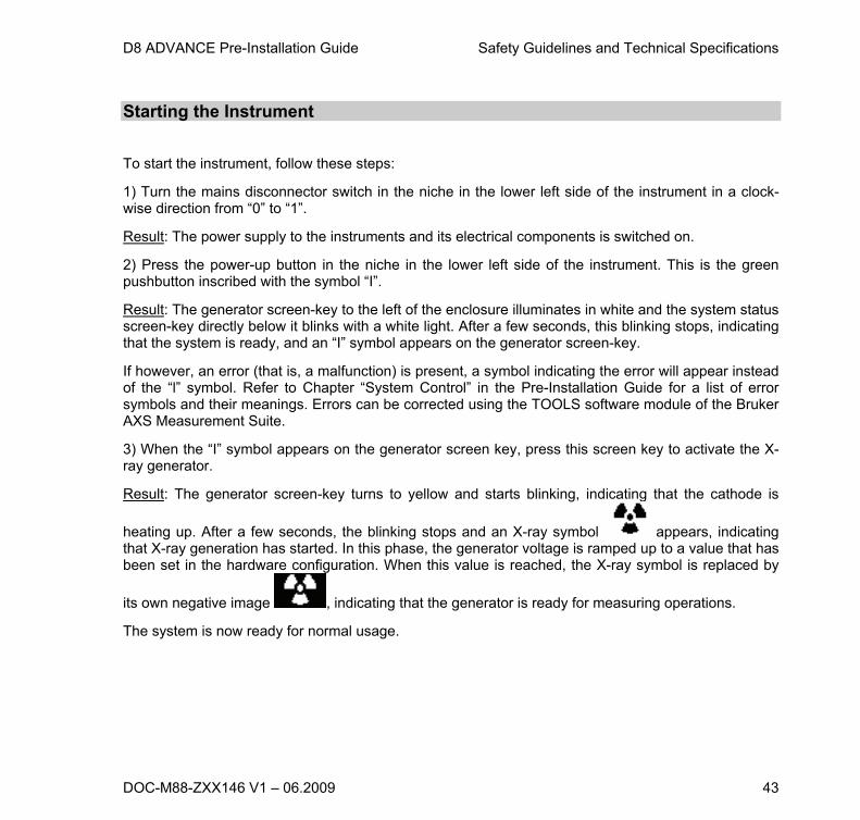
Starting the Instrument
To start the instrument, follow these steps:
1) Turn the mains disconnector switch in the niche in the lower left side of the instrument in a clock-wise direction from “0” to “1”.
Result: The power supply to the instruments and its electrical components is switched on.
2) Press the power-up button in the niche in the lower left side of the instrument. This is the green pushbutton inscribed with the symbol “I”.
Result: The generator screen-key to the left of the enclosure illuminates in white and the system status screen-key directly below it blinks with a white light. After a few seconds, this blinking stops, indicating that the system is ready, and an “I” symbol appears on the generator screen-key.
If however, an error (that is, a malfunction) is present, a symbol indicating the error will appear instead of the “l” symbol. Refer to Chapter “System Control” in the Pre-Installation Guide for a list of error symbols and their meanings. Errors can be corrected using the TOOLS software module of the Bruker AXS Measurement Suite.
3) When the “I” symbol appears on the generator screen key, press this screen key to activate the X-ray generator.
Result: The generator screen-key turns to yellow and starts blinking, indicating that the cathode is
heating up. After a few seconds, the blinking stops and an X-ray symbol appears, indicating that X-ray generation has started. In this phase, the generator voltage is ramped up to a value that has been set in the hardware configuration. When this value is reached, the X-ray symbol is replaced by
its own negative image , indicating that the generator is ready for measuring operations.
The system is now ready for normal usage.

Safety Guidelines and Technical Specifications D8 ADVANCE Pre-Installation Guide
44 DOC-M88-ZXX146 V1 – 06.2009
Powering Down the Instrument To close down the instrument, follow these steps.
1) Press the generator screen-key to ramp down the generator.
Result: The negative X-ray symbol on the screen-key reverts to its original state as the generator volt-age is reduced until X-ray generation ceases. At this point, the screen-key reverts to white and the “l” symbol reappears. You can now switch off the instrument.
2) Press the power-down button, which is the red button inscribed with “Stand-by” in the niche on the lower left side of the instrument.
WARNING
Do not press the power-down button while X-rays are being generated by the high-voltage generator, as indicated by the X-ray symbol on the generator screen key. This can shorten the service lives of the X-ray tube and the high voltage generator.
Result: The instrument is powered down, that is, switched into stand-by mode. The X-ray generator and all drives stop immediately.
3) Turn the mains disconnector switch, that is, the turnkey in the niche in the lower left side of the instrument, in an anti-clockwise direction from “l” to “0”.
Result: The power supply to the instrument and all its electrical components is shut off. Having shut down the instrument in this way, you can remove the connector from the mains socket if necessary.

D8 ADVANCE Pre-Installation Guide Safety Guidelines and Technical Specifications
DOC-M88-ZXX146 V1 – 06.2009 45
Starting the Software All essential measurement-related tasks are performed using the plug-in modules of the Bruker AXS Measurement Suite. When you start the software, the Measurement server, via which the plug-modules communicate with your Bruker AXS X-ray instrument(s), will start automatically in the back-ground.
First, the instrument you want to work with must be selected, a connection between it and the Meas-urement must be set up, and then the Measurement server must be given control of the instrument. You do this via the dialogs Select Instruments and Status Window of the Measurement server. For information on these setting-up steps, see the Chapter “Measurement Server” in the Bruker AXS Measurement Suite User Manual.
Select the COMMANDER module of the Bruker AXS Measurement Suite by clicking on the appropri-ate tab or on the appropriate icon in the outlook bar of the shell interface.
Establish a connection between the Commander module and the instrument via the item “Connect” of the File menu according to the instructions given in the Section “Getting a Connection to an Instrument with the Measurement client” of the Bruker AXS Measurement Suite User Manual.
When a connection has been established between the plug-in and the instrument, the system status screen-key on the instrument will change from white to green. This means that commands can now be sent to the instrument from COMMANDER.

Safety Guidelines and Technical Specifications D8 ADVANCE Pre-Installation Guide
46 DOC-M88-ZXX146 V1 – 06.2009
Protection against Radiation
General Remarks The D8 ADVANCE diffraction system is an analytical instrument with a strong X-ray source. Shielding and safety equipment guarantee that the emitted radiation outside accessible parts of the instrument
does not exceed 1 µSv/h
H *(10) during operation. Bruker AXS screens each single D8 ADVANCE
for X-ray radiation leakage prior to delivery. This is done under worst case conditions. The D8 AD-VANCE is in compliance with the requirements for X-ray systems which are certified as complete pro-tection instrument (‘Vollschutzgerät’) according to the German X-ray safety standard called ‘Röntgen-verordnung’. The D8 is also compliant with the French radiation safety standard AFNOR NFC 74-100.
The enclosure of the diffraction experiment serves as the radiation safety box. It must always be en-sured that the enclosure and the setup of the goniometer correspond to one of the specified configura-tions and that the safety system is always in operation.
The following is necessary to guarantee a radiation-safe design of the X-ray setup:
The tube mount must be attached to the track provided on the goniometer, and the goniometer must be located at one of the pre-defined positions located on the bottom part of the enclosure.
The primary optic bench with its X-ray guiding labyrinths must be mounted. Removal is secured by sealing screw heads. An additional primary optic is not required for guaranteeing radiation protec-tion.
The enclosure must be installed completely. This guarantees that the scattered radiation produced during the measurement is shielded.
All parts which are relevant for radiation safety are either secured by safety interlocks or by using screws with sealed heads (epoxy sealing). See Table 3 for a list of parts which must be secured in such a way.

D8 ADVANCE Pre-Installation Guide Safety Guidelines and Technical Specifications
DOC-M88-ZXX146 V1 – 06.2009 47
Table 3: Some radiation safety relevant parts must be fixed with safety screw. In this context safety screws are screws sealed with two component metal epoxy.
# Position/Verbindung Number of screws
1 Fan backpanel left hand side 2
2 Backpanel angle left hand side 1
3 Backpanel left hand side 1
4 Goniometer base and D8 box 2
5 Connection optical bench and tube mount 1
6 Optical bench - labyrinth tube side 2
7 Optical bench - labyrinth sample side 1
8 Cable labyrinth enclosure left hand side 2
9 "Schmersal" safety switch actuator at the door 2
10 Tube mount movement end stop (track) 1
11 Connection primary track and goniometer 1
12 Shutterplate 1
13 Door magnet 1
There are several warning displays which have the following meanings:
On the right and left side of the enclosure the orange warning displays signal that the X-ray tube is radiating (“X-rays on”). Also the orange warning display at the tube housing indicates generation of radiation.

Safety Guidelines and Technical Specifications D8 ADVANCE Pre-Installation Guide
48 DOC-M88-ZXX146 V1 – 06.2009
The red warning display located at the tube housing mean that the X-ray window is open (“Shutter open”).
The function of all these warning lamps is monitored.
The system can be secured against unauthorized use by a safety lock (Fig. 13).
Fig. 13: System can be secured against unauthorized use by safety lock. Switch On of system is impossible when locked. All internal lines besides those marked by orange isolation are cut from electrical power supply. Generation of X-rays is impossible when system is locked.
DANGER
Staying inside radiation safety enclosure is strictly forbidden! Dose equivalent rates >1000Sv/h might occur inside enclosure in case of open X-ray shutter.

D8 ADVANCE Pre-Installation Guide Safety Guidelines and Technical Specifications
DOC-M88-ZXX146 V1 – 06.2009 49
Special Service Operation Modes Operation as described in this section might only be done by specially trained personnel like Bruker AXS service. In these modes, part of safety system or shielding is not properly working. Personnel must strictly follow local radiation safety laws when applying these special servicing measures. Normal operation and servicing does not require such measures.
The rear panel can be removed for servicing and installation by destroying screws with sealed heads. In this case the X-ray generator must be disabled since system cannot avoid radiation damage in this condition. This should only be done after conscientious consideration that this servicing cannot be done by other measures. Additionally, sound precautions must be taken for avoiding radiation dam-ages by following local legislation. Before restarting routine use of system, rear panel must be put back in place and secured by sealing the screw heads as described in the “Technical obligation for delivery”, (cf.Table 3 on page 47).
The D8 diffraction system has been aligned prior to delivery. A new alignment, even following a tube replacement, is always possible with the enclosure closed.
If it is necessary to align under radiation with the enclosure open, the safety system can be bypassed using the Unprotected Mode Box (UMbox: not in standard D8 – order as an option, fully protected version of D8 is equipped with a safety board where such an UMbox cannot be connected. The safety board must be replaced by a special version which allows for usage of UMbox.). It is forbidden to over-ride the safety functions in any way other than using the UMbox. The red warning displays on the UM-box are flashing when the UMbox has been activated. Only the person responsible for radiation pro-tection measures or other authorized persons have the permission to use the UMbox. The UMbox must be safely guarded by them to prevent abuse.
When the UMbox is activated, the generation and release of X-rays is exclusively the responsibility of the current user. The X-ray shutter can only be activated using the buttons located at the UMbox.
DANGER
During operation with the UMbox the system is unprotected! Working on an unprotected instrument is dangerous! In this case the radiation protection requirements must be strictly observed!

Safety Guidelines and Technical Specifications D8 ADVANCE Pre-Installation Guide
50 DOC-M88-ZXX146 V1 – 06.2009
DANGER
The direct beam of the internal X-ray source is extremely intense. Exposure to radiation for even a few seconds can cause severe burns. Longer exposure can cause severe injury. These injuries can lead to lethal diseases. Even without visible injuries or sensible pain, lethal diseases might evolve. This might happen even after many years. For this reason the radiation regulations must be strictly adhered to!
Working with an unprotected diffractometer is dangerous. Alignment work with an unprotected unit must only be carried out by persons who are subject to personal dose measurements and medical surveillance. Only the lowest values for the high-voltage and tube current are allowed to be used. Use long alignment tools! Never hold your hand in the primary beam! Only remove those parts of the shielding whose removal is essential for the alignment. Generally it is not required to remove the rear panel.
WARNING
Locally valid regulations for the operation of X-ray analytical systems must be observed strictly!
Tube Housing The tube housing is an essential part of the radiation protection features. It has an outlet window for the working beam which can be closed by a 3.7 mm thick W/Cu shutter. There are safety line contacts on the mounting plate of the tube housing which are only closed when the tube mount is installed cor-rectly. Only then, the generator can produce high voltage for X-ray generation.
DANGER
It is forbidden to manipulate the shutter and the surrounding flange plate. Therefore, removal of flange plate is secured by a screw with sealed head.

D8 ADVANCE Pre-Installation Guide Safety Guidelines and Technical Specifications
DOC-M88-ZXX146 V1 – 06.2009 51
X-ray Safety Circuits See documentation A25-X1-X26.
D8 diffraction systems have two totally independent safety circuits. Both safety circuits are directly connected with the safety control unit (implemented with contactors) located inside the X-ray genera-tor. Generation of the high-voltage is only enabled in the X-ray generator when both safety circuits are closed i.e. both signal safe conditions.
Safety Circuit 1: Safety Circuit 1 consists of the shutdown relays K1 and K2, the relay contacts SC1.b (shutter closed) in parallel to DL1.b (door locked), the external interlock 1A (optional), the tube housing mount switch, the relay contact from enclosure line relay K4 and the rip cord which monitors the correct installation of the high-voltage cable. If all switches are closed +24VDC potential will be conducted from the rip cord’s end through the whole line of switches and applied to the X-ray generator’s safety control unit. The +24VDC level switches a contactor which enables the generation of the high-voltage.
Enclosure Line 1: Enclosure Line 1 consists of the enclosure relay K4, the circuit-breakers S654 (right labyrinth) and the external interlock 3A (optional). If all switches are closed +24VDC potential will be conducted through the whole line of switches and activates the enclosure line relay K4.
Safety Circuit 2: Safety Circuit 2 consists of the shutdown relays K1 and K2, the relay contacts SC2.b (shutter closed) in parallel to DL2.b (door locked), the external interlock 2A (optional), the tube housing mount switch, the relay contact from enclosure line relay K3 and the rip cord which monitors the correct installation of the high-voltage cable. If all switches are closed +24VDC potential will be conducted from the rip cord’s end through the whole line of switches and applied to the X-ray generator’s safety control unit. The +24VDC level switches a contactor which enables the generation of the high-voltage.
Enclosure Line 2: Enclosure Line 2 consists of the enclosure relay K3, the circuit-breakers S654 (right labyrinth) and the external interlock 4A (optional). If all switches are closed +24VDC potential will be conducted through the whole line of switches and activates the enclosure line relay K3.
The various components of the safety circuit work as follows:

Safety Guidelines and Technical Specifications D8 ADVANCE Pre-Installation Guide
52 DOC-M88-ZXX146 V1 – 06.2009
Position and orientation of goniometer: The correct position of the goniometer is not surveyed by the safety circuit of the D8 ADVANCE. Therefore, the position and orientation of the goniometer is rigidly fixed by screws which are sealed with epoxy.
Rear panel D8 ADVANCE: Removal of the rear panel is not required for use and maintenance. Therefore, the rear panel is me-chanically secured against removal after installation. Screws on both sides are sealed by epoxy.
Door lock + Door lock relays K5 / K6: The door lock S657 checks if the front door is closed and locked correctly. The door lock contains two switching contacts which are closed if the door is closed and locked. One contact of the door lock is used in series to activate the door lock relay K5, the other two contacts are used in series to activate the door lock relay K6. The safety controller monitors the status of the relays. If it is wrong it will imme-diately open the safety circuit via the relay K1/K2 and thus disable the generation of high-voltage.
With one contact from each relay K5 and K6 in series (DL1.a and DL2.a) the shutter driver was inter-rupted from the shutter coil if the door locks not activated so its not possible to open the shutter if the door is open.
If the X-ray generator is turned on and the door locks are activated the door lock relay contacts DL1.b and DL2.b will bypass the contacts SC1.b and SC2.b of the shutter relays. Thus in that case the user can open and close the shutter.
Rip cord: The rip cord connects safety circuit 1 and 2 to +24VDC potential and monitors correct installation of the high-voltage cable at the tube housing.
Shutter switches: The X-ray shutter position switches are located directly at the tube mount. Each of the two shutter switches activates a relay at the safety board. Shutter switch #1 activates the relay K8 if the shutter is closed; shutter switch #2 activates the relay K7 if the shutter is closed. There is a shutter open switch which is used only for measurement.
If the X-ray generator is turned on and the X-ray shutter is closed the relay contacts SC1.b and SC2.b will bypass the contacts DL1.b and DL2.b of the door locks. Thus in that case the user can open and close the front doors without turning off the X-ray generator.

D8 ADVANCE Pre-Installation Guide Safety Guidelines and Technical Specifications
DOC-M88-ZXX146 V1 – 06.2009 53
If the X-ray shutter is opened, the front door switches are no longer bypassed, the door lock voltage was continuously applied from the safety board (shutter relay contacts SC1.a and SC2.a) so its not possible to open the door locks.
K1/K2: The so-called safety relays K1 and K2 are driven by the safety controller on the safety board. The contacts of K1 and K2 are inserted as well as in safety circuit 1 and safety circuit 2.
K1 and K2 will open the safety circuit and thus shut down the X-ray generator if one or more safety errors were detected. You can see the failure in the history of the Tools (Device-Xray-SafetyBoard -> History).
Control of the X-ray Shutter The X-ray shutter (at the tube housing) is connected with the shutter control unit which is implemented on the Universal IO-Board. If the shutter shall open the control unit provides the X-ray shutter magnet first with an opening voltage pulse and then with a hold current which keeps the shutter window open.
The X-ray shutter will only open if the following five conditions are fulfilled:
4. The generator high-voltage is switched on.
5. The front door is closed and locked correctly.
If one of the conditions fails, the current through the X-ray shutter’s coil will be switched off and the shutter will close immediately driven by a mechanical spring.
If the shutter control logic detects an error the shutdown relay K1 and K2 will open. Consequently the X-ray generator’s high-voltage will be turned off and the X-ray shutter will close.

Safety Guidelines and Technical Specifications D8 ADVANCE Pre-Installation Guide
54 DOC-M88-ZXX146 V1 – 06.2009
Shutter Warning Displays Warning display located at the tube mount:
Red LEDs: The red LED display indicates that the X-ray shutter is not closed, i.e. the X-ray shutter is at least par-tially open and X-ray radiation is emitted through the radiation outlet window into the interior of the X-ray protection box.
The current through the red LEDs is permanently measured. If an error of the display is detected the X-ray shutter will close immediately.
Tube mount interlock The tube mount interlock ensures that the X-ray source can only be mounted and run at certain posi-tions within the radiation protection enclosure. If the tube housing is not mounted the Safety lines 1 and 2 where interrupted and it is not possible to switch on the X-ray generator.
DANGER
Any manipulation could cause injury due to X-rays. If a forced or irregular interlock manipulation is detected, your licence for full radiation protection systems will be revoked.
Resetting the X-ray Safety System The X-ray Safety System is permanently checking the status of all components which are relevant for the X-ray safety. If there are any errors or inconsistencies the safety controller will shut down the X-ray generator immediately. The error which caused the shut-down will be captured and displayed in the Tools (Device-Xray-SafetyBoard -> History).
It is not possible – even after power down and restarting the instrument - to turn on the X-ray genera-tor again until the safety system has been reset. The reset procedure is described in the user manual of the D8 ADVANCE.

D8 ADVANCE Pre-Installation Guide Safety Guidelines and Technical Specifications
DOC-M88-ZXX146 V1 – 06.2009 55
Danger of Radiation
The X-ray safety controller may only be reset if the fault which caused the shut-down has been re-paired and is no longer present! Contact your Bruker AXS Service for help.
The reset of the safety module is protected by password. Resetting requires sufficient user rights.
NOTE
The password is factory-preset to „password“.
Machinery Safety The D8 ADVANCE fulfills the machinery directive 2006/42/EC of the European Union.
Accordingly for all moving drives measures have been taken to avoid injuring people.
For D8 ADVANCE all drives have been categorized by a “Danger Class”. When a drive cannot cause significant injures it is considered as “safe” and is classified as class A. Dangerous drives are classi-fied class B. See Table 4 for finding out the class of a specific drive.
Class B drives can only be moved when the enclosure of the D8 ADVANCE is closed. Whenever the enclosure is opened, any class B drive will stop or not start to move.
On contrary class A drives are allowed to move when the enclosure is opened.
Classification of drives can only be configured at factory.
All drives will be classified automatically as type B (dangerous) if not explicitly listed in Table 4 as class A.
Safety Guidelines and Technical Specifications D8 ADVANCE Pre-Installation Guide
56 DOC-M88-ZXX146 V1 – 06.2009
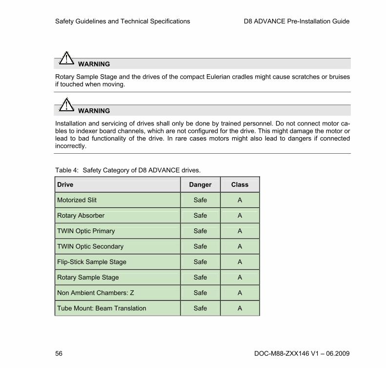
WARNING
Rotary Sample Stage and the drives of the compact Eulerian cradles might cause scratches or bruises if touched when moving.
WARNING
Installation and servicing of drives shall only be done by trained personnel. Do not connect motor ca-bles to indexer board channels, which are not configured for the drive. This might damage the motor or lead to bad functionality of the drive. In rare cases motors might also lead to dangers if connected incorrectly.
Table 4: Safety Category of D8 ADVANCE drives.
Drive Danger Class
Motorized Slit Safe A
Rotary Absorber Safe A
TWIN Optic Primary Safe A
TWIN Optic Secondary Safe A
Flip-Stick Sample Stage Safe A
Rotary Sample Stage Safe A
Non Ambient Chambers: Z Safe A
Tube Mount: Beam Translation Safe A
D8 ADVANCE Pre-Installation Guide Safety Guidelines and Technical Specifications
DOC-M88-ZXX146 V1 – 06.2009 57
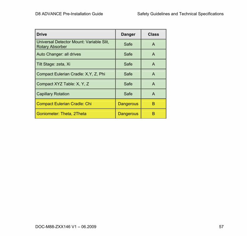
Drive Danger Class
Universal Detector Mount: Variable Slit, Rotary Absorber
Safe A
Auto Changer: all drives Safe A
Tilt Stage: zeta, Xi Safe A
Compact Eulerian Cradle: X,Y, Z, Phi Safe A
Compact XYZ Table: X, Y, Z Safe A
Capillary Rotation Safe A
Compact Eulerian Cradle: Chi Dangerous B
Goniometer: Theta, 2Theta Dangerous B

Safety Guidelines and Technical Specifications D8 ADVANCE Pre-Installation Guide
58 DOC-M88-ZXX146 V1 – 06.2009
Maintenance of the Diffraction System
Servicing Precautions To ensure that the diffractometer system will operate in a reliable and precise way, the maintenance intervals must be obeyed as recommended by Bruker AXS.
All repairs, adjustments and alignments performed at any components of the diffraction system (incl. host computer) must be carried out strictly in accordance with the approved works practices of the country where the equipment is installed.
The electronic modules contain electro statically sensitive devices. Before any components or mod-ules are touched, the service person should discharge himself by touching an earthed object.
The components must only be connected to the plugs of the modules provided for them. The block diagram (see supplement folder) provides information. The plugs of the modules are not protected against the insertion of incorrect components.
WARNING
The incorrect connection of modules or components may result in substantial damage in the system. Therefore thoroughly check all such operations before switching on the power supply.
Cleaning the Diffraction System For cleaning the interior of the enclosure use dry cleaning utensils only. Do not use water or aggres-sive cleansing agents. The front doors can be cleaned with any standard household-type window de-tergent.
CAUTION
Before starting cleaning you must turn off the power of the complete diffraction system, i.e. both con-trol electronics, accessory components and high voltage generator!

D8 ADVANCE Pre-Installation Guide Safety Guidelines and Technical Specifications
DOC-M88-ZXX146 V1 – 06.2009 59
Maintenance of the Diffractometer Measuring Equipment The components of the diffractometer measuring equipment are mainly maintenance-free.
It is recommended to regularly check and maintain the following components by Bruker AXS service people.
Goniometer
Clean or replace and lubricate the lubricating brushes at the worm drives for theta and 2theta.
Only use the lubricant "Molymagnus NT-3" which is supplied by Wiho-Chemie, Virchowstr. 7, D-90409 Nürnberg and manufactured by Strub & Co. AG, Ch-6260 Reiden.
Sample Changer
Clean the gear meshing and lubricate using commercial grease.
Safety Guidelines and Technical Specifications D8 ADVANCE Pre-Installation Guide
60 DOC-M88-ZXX146 V1 – 06.2009
Maintenance of the Optional Internal Cooling Unit (A14-A6)
Checking the Ion Exchanger In order to ensure that the ion exchanger functions correctly, it is recommended to check the conduc-tivity of the cooling water regularly, i.e. approximately every 2 weeks. The conductivity can be read out using the diagnosis program TOOLS inside Bruker AXS measurement suite.
See the value of ‘Cooling water conductivity [S]’ in "Device/XRay/Water Cooling". It should never be larger than 5.1 S. In case this threshold value is exceeded contact your Bruker AXS service.
Checking the Cooling Water Level The level of the cooling water inside the internal water reservoir is monitored permanently by the D8 system control.
If the water level falls below the so-called ‚warning level‘, TOOLS inside the Bruker AXS Measurement Suite will display a warning message and prompt the user to refill the water tank. It is recommended to fill up the cooling water as soon as possible, i.e. within the next few hours.
The status of the fill height sensor can be read out all time using the diagnosis program TOOLS. If a water level warning is pending, the flag ‚Water Level too Low‘ will be checked (see the tree view form called ‚Device/XRay/Water Cooling‘).
If the cooling water is not filled up in time a cooling water alarm will occur. The red status LED will illuminate permanently. In this case the high voltage and the tube current will be forced to 0kV/0mA until the water has been refilled. The system will deny any measurement tasks.
In case of a water level alarm the alarm register ‚Cooling water conductivity too high’ and ‘Water Level too Low‘ will be checked (see the tree view form called ‚Device/XRay/Water Cooling‘).
Refilling the Cooling Water Tank The cooling unit A14-A6 is located underneath the X-ray generator. In order to refill the water tank perform the following steps:
Disconnect the D8 diffractometer system completely from the mains supply (cf. System Power Control. Turn system power cut to “0”.
D8 ADVANCE Pre-Installation Guide Safety Guidelines and Technical Specifications
DOC-M88-ZXX146 V1 – 06.2009 61
Remove the front panel.
Move the cooling unit slightly out of the cabinet (Fig. 15).
Open the cover of the water tank (Fig. 14, Fig. 15).
Pour water into the water tank. Pour water into the water tank. Stop filling in when the water level is about 10mm below the upper edge of the tank.
Close the cover of the tank.
Close the front panel. Do not forget to attach the ground cable again.
Turn on the system and check the flag‚ cooling water level out of range inside TOOLS of the Bruker AXS Measurement Suite ( Device/XRay/Water Cooling). The Alarm Register “Water Level too Low” should not be checked any more.
DANGER: Risk of electrical shock
When the equipment is connected to the mains supply, some terminals of the mains distribution unit will be live. In addition the various modules inside the system will be powered. Therefore it is abso-lutely necessary to switch off the external mains supply before opening any side panels. It is not suffi-cient to just press the D8’s ‘Stand-by ’ button. The mains supply must be switched off externally by the shutdown turn-key or external circuit breaker.
Be very cautious when refilling the water tank. Water may not splash onto any electronic components. Risk of electrical shock!

Safety Guidelines and Technical Specifications D8 ADVANCE Pre-Installation Guide
62 DOC-M88-ZXX146 V1 – 06.2009
Fig. 14: Rear view of the optional internal cooling water unit (A14-A6).
Ion filter K120-C7

D8 ADVANCE Pre-Installation Guide Safety Guidelines and Technical Specifications
DOC-M88-ZXX146 V1 – 06.2009 63
Fig. 15: Refilling the water tank of the internal cooling water supply. Water tank is already open.
Opening Water Tank

Safety Guidelines and Technical Specifications D8 ADVANCE Pre-Installation Guide
64 DOC-M88-ZXX146 V1 – 06.2009
Technical Specifications
General Diffraction System
Tab. 1: Technical Specifications: General Diffraction System.
Mechanical Specifications
Weight of complete system ready for operation (includes: generator, cool-ing unit, electronics, goniometer with standard sample stage, X-ray source, X-ray optics, scintillation detector)
770 kg
Weight of the enclosure and cabinet without equipment (goniometer, sample stage, X-ray source, X-ray optics, detector)
620 kg
Area load per m2 of the floor (ready for operation, system standing on integrated casters: 66cm x 90cm)
1300 kg/m2
Clearance of doors for transportation 86 cm (34”)
Height (Cabinet and Enclosure ready for operation) 1868 mm (73,5”)
Width (Cabinet and Enclosure ready for operation) 1300 mm (51,2”)
Depth (Cabinet and Enclosure ready for operation) 1135 mm (44,7”)
Space inside enclosure: Height 956 mm (37.6”)
Space inside enclosure: Width 1014 mm (39.9”)
Space inside enclosure: Depth 1037 mm (40.8”)
Transport size on casters: Height 1300 mm (51.2”)
Transport size on casters: Width 1868 mm (73.5”)
Transport size on casters: Depth 854 mm (33.6”)
Environmental Specifications
Temperature operation range 15 – 35°C, recommended temperature range 20°C - 28°C
Maximum temperature gradient 1.0°C per hour
Relative humidity 20%-80%, condensation not allowed
Atmospheric pressure Diffraction system applicable at all terrestrial locations under atmospheric air pressure conditions

D8 ADVANCE Pre-Installation Guide Safety Guidelines and Technical Specifications
DOC-M88-ZXX146 V1 – 06.2009 65
Cooling Water Requirements
Minimum Flow Rate 3.6 l/min
Pressure of Cooling Water Supply 4 to 7.5 bar
Pressure of Cooling Water Discharge Pressure-free
Operating Water Temperature 10 to 25° C, 15 to 20° C recommended (avoid condensation)
Diameter of Cooling Water Supply 1/2“
Water filter (water supply) Mesh size 0.15 mm (100 mesh)
NOTE
Assuming a relative humidity of 80% and a room temperature of 30 °C the dew point is 26 °C, at a room temperature of 25 °C the dew point is 21 °C, respectively. In case the head of the tube housing has a temperature equal or lower than the dew point condensation will occur.

Safety Guidelines and Technical Specifications D8 ADVANCE Pre-Installation Guide
66 DOC-M88-ZXX146 V1 – 06.2009
Safety Specifications
Electrical Safety:
European Council Directive, 2006/95/EC IEC 61010-1:2001 (second edition) CSA C22.2 No. 1010
Electromagnetic Compatibility: European Council Directive 2004/108/EC EN 61000-6-2: 2005, EN 61000-6-1: 2007 EN 61000-6-3: 2007, EN 61000-6-4: 2007
Safety of Machinery: EN 1050 Machinery Directive 2006/42/EC European Union
Radiation Safety:
leakage < 1µSv/h
H *(10)
Directive 96/29/EURATOM European Union
German Law ‘Röntgenverordnung’: Pattern approval as fully protected system according §8, Anlage 2 Nr. 3 RöV
French radiation safety standard: AFNOR NFC 74-100
Safety circuitry category 3 according DIN EN 954-1, DIN 54113 part 2
American radiation safety: FDA accession number 880058-000
Each D8 System runs through an individual radiation safety test
Electrical Protection Classification: Class I according IEC 536
Protection Degree against water and for-eign objects:
IP 2 0 according IEC 529
Acoustic Noise: 54 dB(A) according EN ISO 7779/2001-05-01 (up to measurement speeds of 150°/min)
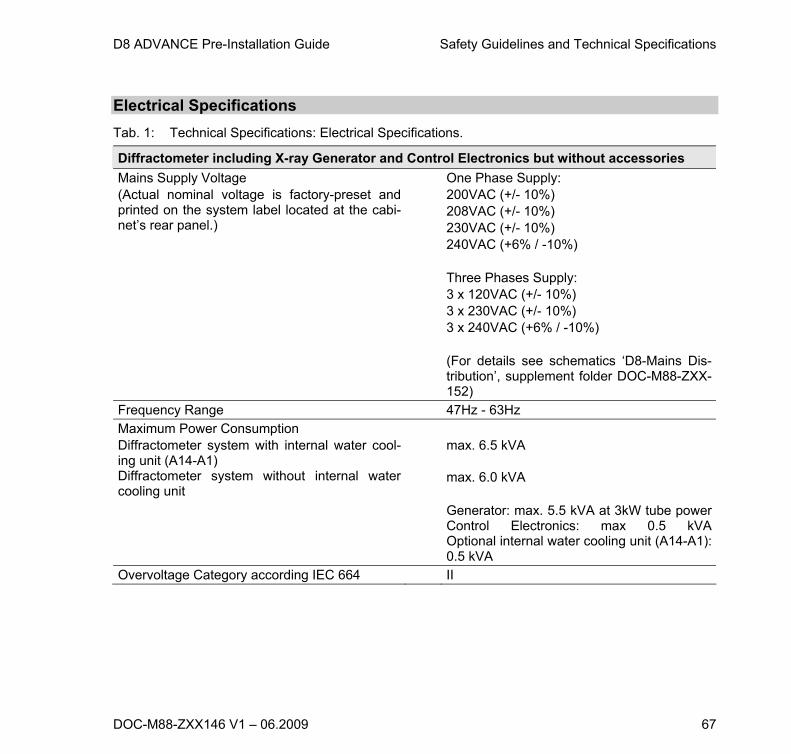
D8 ADVANCE Pre-Installation Guide Safety Guidelines and Technical Specifications
DOC-M88-ZXX146 V1 – 06.2009 67
Electrical Specifications
Tab. 1: Technical Specifications: Electrical Specifications.
Diffractometer including X-ray Generator and Control Electronics but without accessories
Mains Supply Voltage (Actual nominal voltage is factory-preset and printed on the system label located at the cabi-net’s rear panel.)
One Phase Supply: 200VAC (+/- 10%) 208VAC (+/- 10%) 230VAC (+/- 10%) 240VAC (+6% / -10%) Three Phases Supply: 3 x 120VAC (+/- 10%) 3 x 230VAC (+/- 10%) 3 x 240VAC (+6% / -10%) (For details see schematics ‘D8-Mains Dis-tribution’, supplement folder DOC-M88-ZXX-152)
Frequency Range 47Hz - 63Hz
Maximum Power Consumption Diffractometer system with internal water cool-ing unit (A14-A1) Diffractometer system without internal water cooling unit
max. 6.5 kVA max. 6.0 kVA Generator: max. 5.5 kVA at 3kW tube powerControl Electronics: max 0.5 kVAOptional internal water cooling unit (A14-A1): 0.5 kVA
Overvoltage Category according IEC 664 II

Safety Guidelines and Technical Specifications D8 ADVANCE Pre-Installation Guide
68 DOC-M88-ZXX146 V1 – 06.2009
Diffraction Components
Tab. 2: Technical Specifications: Diffraction Components.
Goniometer
Measuring Circle Diameters Standard: 500 mm (SNAP.LOCK) Optional: 560 mm (TWIN/TWIN) Possible: 280…720mm depending on technical details
Operating Position vertical
Goniometer Angular Range of Theta and 2-Theta
360° (depending on mountings)
Step Width 0.0001 degree
Angular Range diffraction system (max. range depends on accessories) Theta 2Theta
-6°…179° (Theta-Theta instrument) 360° (Theta-2Theta instrument) 170°
Central Clearance in Theta ring 100 mm
Theta and 2-Theta drive controlled by two independent stepper motors
Velocity max. 1500°/min (dependent on hardware setup)
Scanning Velocity max. 150°/min (dependent on hardware setup)
Axial Thrust Torque on Axis
500N 1000 Ncm