dallas area rapid transit - dart.org · tof-1 may 2005 revision 4 2 figure 1-1, roll and...
TRANSCRIPT

Dallas Area Rapid TransitLight Rail Project
Design Criteria Manual
Volume 2
Systems Design
May 2005

Design Criteria Volume 2
System Design
Revision History
As of January 2007
Revision Number
0 1 2 3
4 5
Revision Date 07/88 12/90 03/92 01/02
05/05 01/07
Description of Changes
PBCD Issur Revision 1 Chapters 10-12/MKE Rev "B" Chapters 10-12/FRHarris/KJM Issued 05/02 All Chapters Revised Chapters 10-12/DMJM Harris
Document Number
BR7Y-002-00-0788 BR7Y-002-01-1290 BR7Y-002-02-0392 BR7Y-002-03-0102
BR7Y-002-04-0505 BR7Y-002-05-0107

Design Criteria Manual, Volume 2, Systems DesignTable of Contents
Section Description Page
TOC-1 May 2005 Revision 4
CHAPTER 1, GENERAL
1.1 GENERAL 1-11.2 LIGHT RAIL DESCRIPTION 1-11.3 SYSTEM CHARACTERISTICS 1-11.4 SYSTEM REQUIREMENTS 1-41.5 APPLICATION OF DESIGN CRITERIA, VOLUME 2 1-6
CHAPTER 2, VEHICLES
2.1 GENERAL 2-12.2 SYSTEM CONSTRAINTS 2-22.3 CAR BODY 2-132.4 COUPLER 2-172.5 OPERATOR'S CAB 2-182.6 PASSENGER DOORS AND CONTROLS 2-182.7 HEATING, VENTILATION, AND AIR CONDITIONING 2-202.8 LIGHTING 2-212.9 AUXILIARY ELECTRICAL SYSTEM 2-222.10 PROPULSION SYSTEM 2-232.11 TRUCK 2-242.12 FRICTION BRAKES 2-242.13 COMMUNICATIONS 2-252.14 AUTOMATIC TRAIN PROTECTION (ATP), TRIP STOP
SYSTEM (TSS) AND TRAIN-TO-WAYSIDECOMMUNICATIONS (TWC) 2-26
2.15 FLAMMABILITY and SMOKE EMISSIONS 2-262.16 CLEARANCES 2-262.17 LOAD DISTRIBUTION 2-28
CHAPTER 3, TRACTION ELECTRIFICATION
3.1 GENERAL 3-13.2 SYSTEM DESCRIPTION 3-13.3 CODES AND STANDARDS 3-23.4 GENERAL 3-23.5 TRACTION POWER SUBSTATIONS 3-53.6 DC FEEDER SYSTEM 3-113.7 OVERHEAD CONTACT SYSTEM (OCS) 3-123.8 SIGNAL AND COMMUNICATIONS POWER 3-18
SUPPLY SYSTEM3.9 INTERFACES 3-18

Design Criteria Manual, Volume 2, Systems DesignTable of Contents
Section Description Page
TOC-2 May 2005 Revision 4
CHAPTER 4, SIGNAL SYSTEM
4.1 GENERAL 4-14.2 VITAL FUNCTIONS 4-74.3 NON-VITAL FUNCTIONS 4-164.4 SYSTEM CONTROL 4-164.5 NON-VITAL ELECTRONIC CIRCUITS 4-204.6 ENERGY DISTRIBUTION CIRCUITS 4-204.7 WAYSIDE SIGNAL EQUIPMENT 4-234.8 HIGHWAY GRADE CROSSINGS 4-304.9 YARD SIGNAL SYSTEM 4-324.10 INTERFACES 4-324.11 ABBREVIATIONS 4-334.12 DEFINITIONS 4-34
CHAPTER 5, COMMUNICATIONS
5.1 GENERAL 5-15.2 DESCRIPTION 5-15.3 COMMUNICATIONS SUBSYSTEMS SCOPE 5-15.4 DESIGN REQUIREMENTS 5-135.5 INTERFACING REQUIREMENTS 5-185.6 ABBREVIATIONS AND DEFINITIONS 5-24
CHAPTER 6, TRAIN CONTROL CENTER ANDSUPERVISORY CONTROL SYSTEM
6.1 GENERAL 6-16.2 TCC STAFF OPERATING FUNCTIONS 6-26.3 TCC PHYSICAL DESCRIPTION 6-76.4 LIGHT RAIL SUPERVISORY CONTROL SYSTEM 6-116.5 REQUIREMENTS FOR INTERFACE TO OTHER SYSTEMS 6-16
CHAPTER 7, FARE COLLECTION
7.1 GENERAL 7-17.2 TICKET VENDING MACHINES 7-17.3 TICKET VENDING MACHINE HARDWARE REQUIREMENTS 7-57.4 RELIABILITY AND MAINTAINABILITY 7-77.5 SECURITY 7-77.6 CENTRALIZED DATA COLLECTION SYSTEM 7-87.7 VALIDATORS 7-9

Design Criteria Manual, Volume 2, Systems DesignTable of Contents
Section Description Page
TOC-3 May 2005 Revision 4
CHAPTER 8, CORROSION CONTROL
8.1 GENERAL 8-18.2 SOIL CORROSION CONTROL (BURIED STRUCTURES) 8-28.3 STRAY CURRENT CORROSION CONTROL 8-118.4 ATMOSPHERIC CORROSION PREVENTION 8-21
CHAPTER 9, SYSTEM GROUNDING AND RACEWAYS
9.1 PURPOSE 9-19.2 GENERAL 9-19.3 CODES AND STANDARDS 9-19.4 DESIGN CONSIDERATIONS 9-29.5 INTERFACES 9-49.6 DUCT BANKS 9-4
CHAPTER 10, OPERATIONS
10.1 GENERAL 10-110.2 OPERATIONS 10-110.3 FACILITIES 10-610.4 SUPERVISORY CONTROL 10-810.5 SECURITY 10-910.6 SYSTEM SAFETY 10-10
CHAPTER 11, RELIABILITY AND MAINTAINABILITY
11.1 INTRODUCTION 11-111.2 LIGHT RAIL VEHICLES 11-1211.3 TRACTION ELECTRIFICATION SYSTEM 11-1611.4 SIGNALS 11-1611.5 COMMUNICATIONS 11-1711.6 GLOSSARY OF TERMS 11-19

Design Criteria Manual, Volume 2, Systems DesignTable of Contents
Section Description Page
TOC-4 May 2005 Revision 4
CHAPTER 12, SYSTEMS SAFETY
12.1 INTRODUCTION 12-112.2 LIGHT RAIL VEHICLES 12-2112.3 COMMUNICATIONS 12-2912.4 TRACTION ELECTRIFICATION 12-3412.5 SIGNAL SYSTEM 12-3912.6 FIRE/SECURITY SUBSYSTEMS 12-4312.7 TRAIN CONTROL CENTER (TCC) 12-5212.8 YARD CONTROL 12-5612.9 ENVIRONMENTAL PROTECTION 12-5612.10 DEFINITIONS 12-59

Design Criteria Manual, Volume 2, Systems DesignTable of Figures
Chapter Title Page
TOF-1 May 2005 Revision 4
2 Figure 1-1, Roll and Superelevation 2-292 Figure 1-2, LRV Design Load Distribution 2-302 Figure P2, Lower Corner of Carbody 2-312 Figure P3, Intermediate Point of Carbody 2-322 Figure P4, Upper Corner of Mirror 2-332 Figure P5, Upper Corner of Carbody 2-342 Figure P6-P8, End of Pantograph 2-352 Figure P9, Upper Corner of Carbody 2-362 Figure P10, Upper Corner of Mirror 2-372 Figure P11, Intermediate Point of Carbody 2-382 Figure P12, Lower Corner of Carbody 2-392 Figure P13-P15, Intermediate Point of Pantograph 2-402 Figure P16-P18, Intermediate Point of Pantograph 2-412 Figure P19-P21, End of Pantograph 2-422 Figure P22-P24, Center of Pantograph 2-43

CHAPTER 1
GENERAL SECTION

Design Criteria Manual General, Chapter 1
1-i May 2005 Revision 4
Chapter 1
GENERAL SECTION
Table of Contents
Section Page
1.1 GENERAL 1-1
1.2 LIGHT RAIL DESCRIPTION 1-1
1.3 SYSTEM CHARACTERISTICS 1-1
1.3.1 Starter System 1-21.3.1.1 Central Business District (CBD) 1-21.3.1.2 Oak Cliff Line (OC) 1-21.3.1.3 West Oak Cliff Line (WOC) 1-21.3.1.4 South Oak Cliff Line (SOC) 1-21.3.1.5 North Central Line (NC) 1-21.3.1.6 Service and Inspection (S&I) Facility 1-21.3.2 Buildout Phase 1 1-31.3.2.1 North Central Line (NC) 1-31.3.2.2 Northeast Line (NE) 1-31.3.2.3 Service and Inspection (S&I) Facility 1-31.3.3 Buildout Phase 2 1-31.3.3.1 Southeast Line (SE) 1-31.3.3.2 Northwest Line (NW) 1-31.3.3.3 DFW/Irving Line (I) 1-41.3.3.4 Rowlett Extension, Northeast Line (NE) 1-41.3.3.5 Yard Facilities 1-4
1.4 SYSTEM REQUIREMENTS 1-4
1.4.1 Service Requirements 1-41.4.2 Train Operations 1-41.4.3 Environmental Conditions 1-51.4.4 Track Standards 1-51.4.5 Traction Electrification Standards 1-61.4.6 Vehicle Requirements 1-6
1.5 APPLICATION OF DESIGN CRITERIA, VOLUME 2 1-6

Design Criteria Manual General, Chapter 1
1-1 May 2005 Revision 4
CHAPTER 1 - GENERAL SECTION
1.1 GENERAL
The Dallas Area Rapid Transit (DART) Transit System Plan includesa light rail system connecting the Central Business District (CBD)with residential and other areas within the City of Dallas andsurrounding cities of Addison, Carrollton, Cockrell Hill, FarmersBranch, Garland, Glenn Heights, Highland Park, Irving, Plano,Richardson, Rowlett, and University Park.
1.2 LIGHT RAIL DESCRIPTION
The DART Light Rail System is being constructed in phases. TheStarter System was the first phase. It was followed by BuildoutPhase 1, and Buildout Phase 2 is under design.
The Starter System consists of approximately 20 miles of main linedouble track railroad together with a Service and Inspection (S&I)Facility. The Starter System construction includes at-grade,aerial, underground, and street running. It operates south fromPark Lane through Downtown to an Oak Cliff trunk with branches toSouth Oak Cliff and West Oak Cliff.
Buildout Phase 1 consisted of approximately 22 miles of main linedouble track railroad including at-grade and aerial running. Theexisting S&I Yard was expanded to include a rail VehicleAcceptance Facility (VAF) and two additional vehicle shop tracks,11 storage tracks, and two running tracks. The Phase 1 main linebuildout operates north from Park Lane to Parker Road as well aseast from Mockingbird Lane to Downtown Garland.
The planned Buildout Phase 2 will add approximately 45 miles tothe completed Starter System and Phase 1 Buildout. This Phase willalso provide additional S&I Facility storage tracks and expand itsmaintenance shop. A second service facility, the Northwest RailOperating Facility (NWROF), will also be designed and constructed.Buildout Phase 2 will operate southward from the east CBD toBuckner and northward from the west CBD to Frankford Road inCarrollton with a branch line operating from Northwest Highwaythrough Irving to DFW Airport North. There will also be anextension from Downtown Garland to Rowlett.
1.3 SYSTEM CHARACTERISTICS
The Starter System and Buildouts are separated into a number ofline sections, each section covering a particular portion of thealignment.

Design Criteria Manual General, Chapter 1
1-2 May 2005 Revision 4
1.3.1 Starter System
1.3.1.1 Central Business District (CBD)
The CBD contains a Transit Mall that operates from Houston Streetand Pacific Avenue west of CBD to Hawkins and Central Expresswayeast of the CBD. The alignment is predominantly street runningover portions of Pacific Avenue and Bryan Street and includes fourpassenger stations.
1.3.1.2 Oak Cliff Line (OC)
The OC Line operates from the west CBD. The line continues southto 8th and Corinth Streets where it divides into a west and asouth branch. The alignment is a combination of at-grade andaerial construction with a major structure crossing the TrinityRiver. This line has four passenger stations with a connection tothe Trinity Railway Express (TRE) at Union Station. This linesection is signalized from Union Station to Oak Ciff Junction andit connects to the S&I Facility via two yard lead tracks.
1.3.1.3 West Oak Cliff Line (WOC)
The WOC Line is a continuation of the Oak Cliff Line. It operatesjust south of 8th and Corinth Streets to its western terminationat Illinois Avenue and Westmoreland Road. The alignment isprincipally at-grade with a few minor aerial structure portionsover creeks and some retained fill. There are four passengerstations, and a terminal interlocking. This line section is line-of-sight operation, i.e., not signaled.
1.3.1.4 South Oak Cliff Line (SOC)
The SOC Line is a continuation of the Oak Cliff Line. It operatesjust south of 8th and Corinth Streets to its southern terminationat Ledbetter Drive. The alignment is totally at-grade with medianrunning. There are five passenger stations. This line section isline-of-sight operation, i.e., not signaled.
1.3.1.5 North Central Line (NC)
The NC Line is a continuation of the CBD. It operates from Hawkinsand Central Expressway east of the CBD to its northern terminationat Park Lane and Greenville Avenue. The alignment consists of allmajor construction types including at-grade, cut and cover, boredtunnels, retained cut, "U" walls, and aerial structures. Thisline section is signalized from Hawkins to Mockingbird and it isline-of-sight operation between Mockingbird and Park Lane.
1.3.1.6 Service and Inspection (S&I) Facility
The S&I Facility is located on Oak Lane south of Downtown, and itis connected to the OC Line via lead tracks. The Starter SystemFacility consisted of a storage yard, a maintenance building, and

Design Criteria Manual General, Chapter 1
1-3 May 2005 Revision 4
a maintenance-of-way building. The Maintenance Building supportsCentral Rail Operating Division, Fleet Maintenance, Train ControlCenter, Bus Control Center and Transit Police Dispatch. TheMaintenance-Of-Way Building supports Ways, Structures, and TheAmenities Maintenance Department.
1.3.2 Buildout Phase 1
1.3.2.1 North Central Line (NC)
The NC Line is a continuation of Starter System. It operates fromPark Lane to the Parker Road Transit Center at Park Boulevard andArcherwood Street. The alignment consists of at-grade sectionsand aerial structures. There are ten passenger stations includingfour aerial, one pocket track, seven interlockings, two 500 footlong tail tracks, and a NC/NE junction (Katy) located immediatelynorth of Mockingbird Lane. The line section is signalized and theexisting section between Mockingbird and Park Lane was upgradedfrom line-of-sight operation to signalized operation.
1.3.2.2 Northeast Line (NE)
The NE Line is a branch of the NC Line. It operates from justnorth of Mockingbird Lane to Downtown Garland. The alignmentconsists of at-grade sections, two tail tracks at DowntownGarland, and aerial structures, four passenger stations, onepocket track, and six interlockings. This line section issignalized.
1.3.2.3 Service and Inspection (S&I) Facility
During the Buildout Phase 1, storage yard track and maintenanceshop capacity were increased. The maintenance-of-way building wasmodified to accommodate a Vehicle Acceptance Facility (VAF).
1.3.3 Buildout Phase 2
1.3.3.1 Southeast Line (SE)
The SE Line will be a new branch that will be connected to ajunction at the east end of the CBD. It will operate fromHawkins/Bryan Street over approximately 10 miles of double trackrailroad to Buckner Boulevard in Dallas. This Line includesstreet running, at-grade sections, yard lead tracks to theexisting S&I, eight passenger stations, and eight interlockings.This line is signalized.
1.3.3.2 Northwest Line (NW)
The NW Line will be a new branch that will be connected to ajunction at the west end of the CBD. It will operate from HoustonStreet over approximately 16.8 miles of double track railroad tothe cities of Farmers Branch and Carrollton, in Denton County.This Line includes a mixture of at-grade and aerial structures

Design Criteria Manual General, Chapter 1
1-4 May 2005 Revision 4
with a short section below grade at Mockingbird Lane. There are11 passenger stations including six aerial in this line, a newservice and inspection facility (NWROF), and a major interlockingat Northwest Highway. A future connection to Love Field Airportmay be included. This line is signalized.
1.3.3.3 DFW/Irving Line (I)
The I Line will be a new branch that connects to the NW Line atNorthwest Highway. It will operate from Northwest Highway overapproximately 13.2 miles of double track railroad to cities ofIrving, Las Colinas, and the DFW Airport. This Line is a mixtureof at-grade and aerial structures with eight passenger stationsand possible street running in Las Colinas. This line issignalized.
1.3.3.4 Rowlett Extension, Northeast Line (NE)
The R Line will be an extension to the existing NE Line. It willoperate from Downtown Garland to the Rowlett Park and Ride overapproximately 4.8 miles of double track railroad. This Line isprincipally at-grade and is a continuation of the existingNortheast Line section. There will be only one passenger stationand it will be located at the Rowlett Park and Ride. This lineis signalized.
1.3.3.5 Yard Facilities
As part of Phase 2, the existing yard’s storage capacity will beincreased to include the addition of six storage tracks. The shopmaintenance area will also be expanded. Buildout Phase 2 willprovide for the design and construction of a yard known as theNorthwest Rail Operating Facility (NWROF).
1.4 SYSTEM REQUIREMENTS
The system shall be designed utilizing the following commoncharacteristics and criteria. These items shall be used by alldesigners involved in the design of any system element. Referenceshould be made to each individual chapter of this criteria toensure that the characteristics listed hereunder are notsuperseded by more stringent characteristics in the particularchapter.
1.4.1 Service Requirements
The Light Rail System shall be designed using the parametersoutlined as follows:
1.4.2 Train Operations
a) Train Headways by Line Section:
Trunk Line: 5 Minutes Peak

Design Criteria Manual General, Chapter 1
1-5 May 2005 Revision 4
Branch Line: 5 Minutes Peak
CBD: 2.5 Minutes Peak
b) Schedule Speed: Average 21 to 25 MPH witha top speed of 65 MPH
c) Station Dwell Time: 20 SEC nominal (varies)
d) For more detail see Operations, Chapter 10.
1.4.3 Environmental Conditions
a) TemperatureMinimum Ambient: 4o FMaximum Ambient: 115o FMaximum Daily Range: 50o F
b) HumidityMinimum: 5 %Maximum: 100 %
c) PrecipitationMaximum Rainfall Rate: 7 IN per HRMaximum Snowfall: 8 IN
Maximum Ice: Infrequent measurable quantities
d) WindAverage wind speed: 10 MPHMaximum wind gust: 70 MPH
1.4.4 Track Standards
a) Gauge 4 FT 8 1/2 IN
b) CurveHorizontal: 100 FT radius MINVertical Crest: 1,640 FT radius MINVertical Sag: 1,640 FT radius MIN
c) Grade 6% MAX
d) SuperelevationActual: 6 IN MAXUnbalanced: 3 IN MAX
e) Maintenance TolerancesBallasted: FRA Class 5Fixed: FRA Class 5

Design Criteria Manual General, Chapter 1
1-6 May 2005 Revision 4
1.4.5 Traction Electrification Standards
a) VoltageNominal Line: 750 VDCMaximum Line: 900 VDCMinimum Line: 525 VDC
b) WireMinimum Height: 14.0 FTMaximum Height: 22.5 FTStatic Clearance: 5 INPassing Clearance: 4 IN
c) Utility Supply 13.2 KV or 24.6 KV
1.4.6 Vehicle Requirements
a) Refer to Design Criteria Manual, Volume 2, Chapter 2,Vehicles
1.5 APPLICATION of DESIGN CRITERIA, VOLUME 2
DART Design Criteria, Volume 2 revision applicability is asfollows:
a) Starter System and Buildout Phase 1 Revision 1 and 2
b) Buildout Phase 2 Revision 3 and 4

CHAPTER 2
LIGHT RAIL VEHICLES
Design Criteria Manual Light Rail Vehicles, Chapter 2
2-i May 2005 Revision 4
Chapter 2
LIGHT RAIL VEHICLES
Table of Contents
Section Page
2.1 GENERAL 1
2.1.1 Service Characteristics 1
2.2 SYSTEM CONSTRAINTS 2
2.2.1 Vehicle Dimensions and Characteristics 22.2.2 Vehicle Weights 42.2.3 Clearances 52.2.4 Track Standards 62.2.5 Traction Power Standards 62.2.6 Performance Requirements 72.2.7 Electromagnetic Interference (EMI) 92.2.8 Noise and Vibration 12
2.3 CAR BODY 13
2.3.1 General 142.3.2 Articulation 142.3.3 Structure 142.3.3.1 Main Body Sections 142.3.3.2 Articulation Section 152.3.3.3 Coupler Pivot 152.3.3.4 Anti-Climber 152.3.3.5 Collision Posts 152.3.4 Configuration 152.3.4.1 Doors 152.3.4.2 Passenger Seats 162.3.4.3 Flooring 162.3.4.4 Windows 162.3.4.5 Destination Sign and Run Number Sign 162.3.4.6 Stop Request 162.3.4.7 Handicapped Accessibility 172.3.4.8 Signage 17
2.4 COUPLER 17
2.4.1 General 172.4.2 Energy Absorption 17

Design Criteria Manual Light Rail Vehicles, Chapter 2
2-ii May 2005 Revision 4
Chapter 2
LIGHT RAIL VEHICLES
Table of Contents
Section Page 2.5 OPERATOR'S CAB 18
2.5.1 General 182.5.2 Layout and Equipment 18
2.6 PASSENGER DOORS AND CONTROLS 18
2.6.1 General 182.6.2 Configuration 192.6.3 Control 192.6.4 Operators 192.6.5 Obstacle Detection 192.6.6 Manual Release 192.6.7 Indication 20
2.7 HEATING, VENTILATION, AND AIR CONDITIONING 20
2.7.1 General 202.7.2 Operational Description 202.7.3 Temperature Control 21
2.8 LIGHTING 21
2.8.1 Interior 212.8.2 Exterior 21
2.9 AUXILIARY ELECTRICAL SYSTEM 22
2.9.1 Pantograph 222.9.2 Auxiliary Power Supply 222.9.3 Low Voltage Power Supply 22 2.9.4 Shop Supply 22
2.10 PROPULSION SYSTEM 23
2.10.1 General 232.10.2 Controls 232.10.3 Protection 23

Design Criteria Manual Light Rail Vehicles, Chapter 2
2-iii May 2005 Revision 4
Chapter 2
LIGHT RAIL VEHICLES
Table of Contents
Section Page
2.11 TRUCK 24
2.11.1 General 242.11.2 Suspension 242.11.3 Structure 242.11.4 Wheels and Axles 24
2.12 FRICTION BRAKES 24
2.12.1 General 242.12.2 Compressor 252.12.3 Disc Brakes 252.12.4 Control Values 25
2.13 COMMUNICATIONS 25
2.14 AUTOMATIC TRAIN PROTECTION (ATP),TRIP STOP SYSTEM (TSS) ANDTRAIN-TO-WAYSIDE COMMUNICATIONS (TWC) 26
2.15 FLAMMABILITY AND SMOKE EMISSIONS 26
2.16 CLEARANCES 26
2.16.1 Clearance Assumptions 262.16.2 Clearance Table Instructions 272.16.3 Reference Drawing and Clearance Tables 27
2.17 LOAD DISTRIBUTION 28

Design Criteria Manual Light Rail Vehicles, Chapter 2
2-1 May 2005 Revision 4
CHAPTER 2 – LIGHT RAIL VEHICLE
2.1 GENERAL
The DART rail vehicle requirements are similar to those ofexisting vehicles at other properties. The configuration ofthe light rail vehicles will be a 3 unit, double articulated,8 axle rail vehicle designated a DART “Super-LRV”. The A and Bunits at the ends of the LRV will be high floor with stepwells. The center unit (C-unit) has a floor height of 16 inabove top of rail (TOR) to provide direct level boarding fromthe platform. Major on board systems are required to be basedon service-proven equipment that has been designed for theduty cycle and environmental conditions in the Dallas, Texasarea. Refer to Design Criteria Manual, Volume 2, Chapter 1 forenvironmental details.
The vehicle design shall include the reliability and safetycriteria defined in this chapter, Design Criteria Manual,Volume 2, Chapter 2.
Applicable federal, state, and local standards, regulations,and laws shall be observed and incorporated into the vehicledesign.
2.1.1 Service Characteristics
The DART Light Rail Transit (LRT) System servicecharacteristics are:
a) Dallas Central Business District
1) Interim surface running on Pacific Avenue/BryanStreet on a transit mall with street-levelboarding from a 15.5 in high curb/platform.
b) Outside Dallas CBD
1) Parallel existing freeways and on railroadrights-of-way with a combination of boardingfrom 8 in. high platforms and portions of theplatform that are raised to 15.5 in to providedirect, level boarding into the center unit ofthe LRVs.
c) Track Elevations

Design Criteria Manual Light Rail Vehicles, Chapter 2
2-2 May 2005 Revision 4
1) LRVs will be operating on track ways that areat-grade with grade separations, in tunnels, andon aerial structures.
d) Station Spacing
1) Varies from 0.5 mile to 3 miles.
e) Schedule Speed
1) Approximately 25 MPH to 35 MPH2) Top speed of 65 MPH.
f) Typical Train Headway
1) Peak periods 5 to 10 minutes2) Off-peak periods 20 minutes
g) Bus Service Interface
1) To and from all nearby bus stops.
h) Parking Facilities
1) Provided at most outlying stations.
i) Elderly and Handicapped Accessibility
1) Fully accessible, direct, level boarding intothe C-unit of the LRVs.
2.2 SYSTEM CONSTRAINTS
This section contains the dimensional and performancerequirements for DART’s light rail vehicles.
2.2.1 Vehicle Dimensions and Characteristics
a) Vehicle Length
1) Between 120 ft and 125 ft over coupler pullingfaces
b) Vehicle Width
1) Between 8.5 ft and 9.5 ft over side sheets
c) Height Over Roof-Mounted Equipment
1) 12.5 ft, MAX above TOR

Design Criteria Manual Light Rail Vehicles, Chapter 2
2-3 May 2005 Revision 4
d) Height Over Locked-Down Pantograph
1) 13.0 ft, MAX above TOR
e) Pantograph Width
1) 6.5 ft ± 1/8 in
f) Pantograph Carbon Width
1) 4.0 ft, MIN
g) Position of Pantograph
1) On/near centerline of a truck
h) Pantograph operating range
1) 13.5 ft to 23.5 ft
i) Level portion of pantograph head
1) 4.5 ft
j) Horizontal dimension of horn
1) 12 in
k) Vertical dimension of horn
1) 9 in to 12 in
l) Pantograph lateral stiffness
1) 1.0 in per 20 lb MAX (horizontal deflection vs.horizontal force)
m) Pantograph upward pressure
1) 20-25 lb
n) Height of Floor
1) High floor section - 40 in, MAX, above TOR2) Low Floor Section - 16 in above TOR
o) Height of first step from 8 in platform
1) 8 in

Design Criteria Manual Light Rail Vehicles, Chapter 2
2-4 May 2005 Revision 4
p) Height of Headlining
1) 7 ft 1 in, MIN, over floor at vehicle centerline
q) Height of Side Door Opening
1) 6.33 ft, MIN, over floor
r) Width of Side Door Opening
1) Cab End 36 in, Articulation End 48 in, C-unit 48in, clear opening
s) Passenger Seats
1) 102 MIN
t) Truck Center-to-Center Distance
1) 28 ft - 32 ft
u) Truck Wheelbase
1) 7 ft - 8 ft
v) Overhang (truck-center to coupler face)
1) 15 ft - 17 ft
w) Wheel Diameter
1) 28 in new, 26 in worn
x) Fordability
1) Vehicles must be able to operate successfully inwater up to 2 in above the top of rail for adistance of 400 ft at speeds up to 10 MPH.
y) Roll
1) Normal Body Roll ± 2.5o
2) Center of rotation 1.25 ft above top of rails3) Maximum Body Roll ± 4o at suspension stops
2.2.2 Vehicle Weights
a) The weight of each passenger and operator shall bebased on an average weight of 155 LBS.
b) AW0 - Empty Car

Design Criteria Manual Light Rail Vehicles, Chapter 2
2-5 May 2005 Revision 4
1) Ready-to-run weight of 140,000 LBS, MAX
c) AW1 - Full Seated Load
1) Full seated passenger load, plus operator, plusAW0 weight
d) AW2 - Full Load
1) Standees at 2.7 sq. ft per passenger (4 pass/sq.m) plus AW1 weight
e) AW3 - Crush Load
1) Standees at 1.8 sq. ft per passenger (6 pass/sq.m) plus AW1 weight
f) AW4 - Design Load
1) Standees at 1.35 sq. ft per passenger (8pass/sq. m) plus AW1 weight.
2.2.3 Clearances
The following worst-case clearances shall be provided withfull suspension travel or failure, structural deflection,wheel wear, track geometry, or any combination of thepreceding:
a) Truck Mounted Equipment
1) 2.5 in, MIN (Excluding Track Brakes)
b) Car Body Mounted Equipment
1) 4.0 in, MIN
c) Car Body Static Clearance Outline
1) See attached Tables
d) Car Body Dynamic Clearance Outline
1) See attached Tables
e) Curve Clearance
1) See attached Tables

Design Criteria Manual Light Rail Vehicles, Chapter 2
2-6 May 2005 Revision 4
2.2.4 Track Standards
The following design standards may be assumed for the track:
a) Track Gauge
1) 4 ft 8.5 in
b) Horizontal Curve Radius
1) 82 ft (25 m), MIN
c) Vertical Curve Radius
1) Crest 1,640 ft, MIN2) Sag 1,640 ft, MIN
d) Grade
1) 7 % MAX
e) Super elevation
1) 6 in MAX
f) Unbalanced Super elevation
1) 3 in MAX
g) Track Maintenance tolerances
1) Ballasted, FRA Class 52) Direct Fixation, FRA Class 53) See Design Criteria Manual, Volume 1, Facilities
Design for detailed track standards.
2.2.5 Traction Power Standards
The following traction power system design standards may beassumed:
a) Nominal line voltage is 750 VDC
b) Maximum line voltage is 900 VDC
c) Minimum line voltage is 525 VDC
d) Contact wire height range is between 13.5 ft and22.5 ft

Design Criteria Manual Light Rail Vehicles, Chapter 2
2-7 May 2005 Revision 4
e) Traction power derivation is 12 pulse rectification
2.2.6 Performance Requirements
The following specified dynamic performance standards shall beprovided for the light rail vehicles based on dry, level,tangent track. The performance rates shall take into accountrotational inertia.
The acceleration performance requirements shall be met withwheels in any condition from new to fully worn at nominal linevoltage over the vehicle load range up to AW2. Above AW2,performance may degrade linearly with increasing weight.Acceleration rates shall include train resistance and gearlosses.
The braking performance requirements shall be met with wheelsin any condition from new to fully worn over the entirevehicle speed and load range, independent of overhead linevoltage, and excluding train resistance and gear losses. Thebraking system is required to maximize the use of the dynamicbrake prior to adding supplemental friction braking (blendedbraking). The friction brake system shall also function as aback up to the dynamic brake systems in the event of dynamicbrake failure. Track brakes shall function in emergencybraking and as commanded by the operator via a separate switchon the operator's console.
a) Vehicle Speed
1) Maximum Operating Speed is 65 MPH2) Minimum Balancing Speed is 70 MPH3) Design Speed is 75 MPH
b) Jerk Limit
1) 3.0 ± 10% MPHPSPS
c) Acceleration Rate
1) Initial Rate is 2.3 MPHPS2) Base Speed is 20 MPH, MIN3) Residual Rate at 65 MPH is 0.25 MPHPS, MIN
d) Time/Distance Performance, AW2 weight
1) Speed: 0 MPH to 50 MPH is 30 SEC, MAX2) Speed: 50 MPH to 65 MPH is 25 SEC, MAX3) The distance traveled in 20 seconds shall not be
less than 600 ft

Design Criteria Manual Light Rail Vehicles, Chapter 2
2-8 May 2005 Revision 4
e) Instantaneous Service Braking Rate
1) 3.0 MPHPS, MIN
f) Instantaneous Emergency Braking Rate
1) Above 30 MPH is 4.0 MPHPS, MIN2) At or below 30 MPH is 6.0 MPHPS, MIN
g) Control Response Dead Times
1) The control response dead times whentransitioning from any mode such as power, brakeor coast, to any other mode, shall be 300milliseconds maximum, excluding jerk limitinginfluences where applicable.
h) Spin-Slide Protection
1) Acceleration mode spin protection shall beprovided and slide protection shall also beprovided in the braking mode for both thedynamic and friction braking systems. Spin-slide detection is to be provided on both a peraxle basis and per vehicle (synchronous) basis.Tractive effort (propulsion or braking) re-application following spin-slide activity shallbe jerk limited. Detection sensitivity is toprovide a system with a 70 percent efficiency,minimum. The spin-slide system should takeadvantage of the speed characteristics of ACinduction motors.
i) Duty Cycle
1) Propulsion and braking system duty cycles shallbe based on the worst-case line round-tripconditions under the following scenario andassuming a passenger load of AW2 without causingdamaging temperatures to equipment:
2) For the propulsion system, 50 percent of thepropulsion units are assumed to have failed, andthe effective propulsion system tractive effort,in both acceleration and dynamic braking, is tobe half the normal value.
3) For the friction braking system, in the event ofdynamic brake failure, the system is to be

Design Criteria Manual Light Rail Vehicles, Chapter 2
2-9 May 2005 Revision 4
capable of full braking performance, at thespecified rates with an automatically imposedspeed restriction of at least 30 MPH, withoutthe need to terminate the run before the end ofthe line.
2.2.7 Electromagnetic Interference (EMI)
The electrical, electronic, and communications systems shalloperate within the DART system and cars without eithersuffering or causing interferences which may adversely impactthe system operation and/or safety because of conducted and/orradiated emissions.
a) Methods and Equipment
1) The Contractor shall employ design techniques,construction methods, and whatever equipment isrequired to prevent interference caused byinternal sources from effecting car systemsproper operation. In addition to coordinatingfrequencies, the Contractor shall providenecessary on-board balancing, filtering,shielding, isolating, and grounding to reduceundesirable interference. Electrostatic andmagnetic shielding methods shall be employed tominimize stray signals and transient voltages oninterconnecting cables. Interconnecting powerand signal cables shall be physically separated.Trainlines shall be located and arranged tominimize voltage induction into train linecircuits due to propulsion system, auxiliarypower, and catenary current transients.
b) Emission Limits
1) To avoid undesirable effects upon the externalenvironment along the right of way as caused byonboard vehicle subsystems, the electromagneticemission limits specified here shall not beexceeded.
c) Radiated Emissions
1) Radiated Emissions as measured by the proceduresfrom “Radiated Interference in Rapid TransitSystems, Volume II: Suggested Test Procedures,UMTA-MA-06-0153-85-11 shall conform to thefollowing:

Design Criteria Manual Light Rail Vehicles, Chapter 2
2-10 May 2005 Revision 4
A. From 0.01 MHz to 30 MHz, the maximumpermissible interference limit shall notexceed 20 dB above the limit of Figure 22(RE05) of MIL-STD-461A.
B. From 30 MHz to 88 MHz, the maximum limitshall be 58 dB above one microvolt/meter/Mhz bandwidth.
C. From 88 Mhz to 1,000 Mhz, the maximumlimit shall be 68 dB above one microvolt/meter/Mhz bandwidth.
2) These limits shall not be exceeded when measuredat a distance of 100 feet from the trackcenterline.
d) Conductive Emissions
1) The conductive emissions, as measured by theprocedures of “Conductive Interference in RapidTransit Signaling Systems, Volume II: SuggestedTest Procedures, UMTA-MA-06-0153-85-6, MethodRT/CEO2A, Conductive Emission Test, Vehicle”,shall have a current limit defined by thefollowing curve:A. 10 A RMS from 1 to 80 HzB. 10 A RMS decreasing to 1 A RMS from 80 to
90 HzC. 1 A RMS from 90 to 120 HzD. 10 A RMS from 120 to 600 HzE. 1 A RMS from 600 to 1,500 HzF. 0.2 A RMS from 1,500 to 4,000 HzG. 0.3 A RMS from 4,000 to 20,000 Hz
2) Each individual piece of power equipment as wellas the simultaneous operation of all car powershall meet this condition.
e) Inductive Emissions
1) The inductive emissions, as measured by theprocedures of "Inductive Interference in RapidTransit Signaling Systems, Volume II: SuggestedTest Procedures, UMTA-MA-06-0153-85-8, shall belimited to a maximum of 20 milivolts, RMS, railto rail, at all frequencies between 0 Hz to 1kHz and a maximum of 10 milivolts from 1 kHzand 20 kHz. Each individual piece of powerequipment as well as the simultaneous operationof all equipment shall meet this condition.

Design Criteria Manual Light Rail Vehicles, Chapter 2
2-11 May 2005 Revision 4
f) Meeting the above requirements does not guaranteeelimination of interference; it is the first levelof defining the interface between the cars and theirintended environment. The Contractor shall beresponsible to reduce the above limits if necessaryto prevent interference with equipment installed onthe wayside and the immediate vicinity.
g) Conducted Disturbances
1) The Contractor shall formulate criteriagoverning generation and toleration ofelectrical disturbances on conductors betweenassemblies. The criteria shall identify thebasic car circuit types and it shall define asuitable comprehensive disturbancesclassification that could be present in eachcircuit type. The criteria shall insure thateach connected assembly shall tolerate thedisturbances introduced simultaneously by any orall assemblies to which it could be connected.In this regard, special attention shall bedirected to the Automatic Trip Stop and otherTrain Control equipment needs. The criteriashall include any required limit modification asdescribed above, on conducted interference intothe catenary and running rails, with levelsselected to prevent interference with signal andcommunications systems which use those circuitsfor their means of operation and communication.These criteria shall be a part of the EMIcontrol plan and shall be submitted forapproval.
h) Inductive Interference
1) The Contractor shall formulate a set of criteriagoverning generation and toleration ofmagnetically coupled disturbances on or betweenassemblies. The criteria shall identify thebasic circuits types present on the car andshall define a suitable comprehensiveclassification of disturbances that could bepresent in each circuit type. The criteriashall insure that each connected assembly shallbe able to tolerate the disturbances introducedsimultaneously by any or all other assemblies towhich it is magnetically coupled.

Design Criteria Manual Light Rail Vehicles, Chapter 2
2-12 May 2005 Revision 4
i) In this regard, special attention shall be directedto the Automatic Trip Stop apparatus needs. Thecriteria shall include any required limitmodifications, as described above, on the inductiveinterference into the catenary and running rails,with levels selected to prevent interference withsignal and communications systems which use thesecircuits for their means of operation andcommunication. These criteria shall be a part ofthe EMC control plan and shall be submitted forapproval.
2.2.8 Noise and Vibration
a) Interior Noise
1) With all auxiliary equipment simultaneouslyoperating normally and the car at rest withwindows and doors closed, on open track, thenoise level in the car interior shall not exceed72 dBA. With any one system or unit exceptventilation, operating at normal conditions, theinterior noise shall not exceed 67 dBa.
2) With all auxiliary equipment including HVACsimultaneously operating at normal conditionswith the car traveling on open track at 40 MPH(64 KPH) the noise level in the car interiorwith windows and doors closed, shall not exceed75 dBA.
b) Wayside Noise Limits
1) Car or train-produced noise levels shall notexceed the following with all auxiliaryequipment operating simultaneously at a distanceof 50 ft (15 m) from centerline of track.
2) Car stationary, empty 68 dBA
3) Empty car on tangent track in maximumacceleration from 40 MPH (64 KPH), in maximumdynamic braking from 40 MPH (64 KPH), or maximumfriction braking from 40 MPH (64 KPH) (whicheveris worse) 76 dBA
4) For this test, the car shall be operated at alocation approved by DART, on open tie andballast track, with welded, ground, and un-corrugated rail.
Design Criteria Manual Light Rail Vehicles, Chapter 2
2-13 May 2005 Revision 4
5) Noise levels produced by traction motors andgear sets of a complete truck, mounted under thecar body, with all wheels spinning under no-loadconditions at all speeds from zero to theequivalent of 70 MPH (98 KPH) shall not exceed88 dBA at a distance 16 ft from the center ofthe truck on the horizontal plane passingthrough the axles.
6) Noise produced by individual pieces ofcontinuously-operating under car or roof-mountedequipment or systems except traction motors,gears and other equipment which operate onlyoccasionally, such as a circuit breaker orpneumatic venting, HVAC, and air compressoretc., shall not exceed 80 dBA at 16 ft (4.8 m)from the centerline of the equipment while theequipment is operating at normal conditions withthe car at rest. The equipment shall becomplete, installed, and all components of eachsystem operating during this test for noiselevels.
7) Noise levels produced by the individual piecesof under car or roof-mounted equipment whichoperate occasionally, such as a circuit breakeror a pneumatic pressure relief device, shall notexceed 100 dBA at 16 ft (4.8 m) from the centerof the equipment. The level shall be measuredusing the fast meter response setting. Theequipment shall be complete, installed, and allcomponents of each system operating during thesetests for noise levels.
c) Vibrations
1) All vehicle equipment shall be designed tooperate without damage or degradation ofperformance when subjected to vibration andshocks encountered during normal service.
2.3 CAR BODY
The car body design is of prime importance to DART. Thevehicle appearance must be futuristic with sleek lines and aclean exterior. The vehicles may operate in three car trainswith the capability of a three car train to tow another threecar train (6 cars total). This section describes the basicparameters for the car body.

Design Criteria Manual Light Rail Vehicles, Chapter 2
2-14 May 2005 Revision 4
2.3.1 General
The car body shall consist of three car body units and twoarticulation units that semi-permanently connect the three carbody units together. The vehicle is to be fabricatedpredominantly from low-alloy, high-tensile (LAHT) steel andassembled by welding. The exterior skin shall function aspart of the load carrying structure. Each end of a vehicleshall be equipped with an anti-climber and collision posts.The vehicle end caps may be fabricated using moldedfiberglass. The vehicle exterior shall be painted usingpolyurethane paint. Feature stripes shall be applied usingdecals.
2.3.2 Articulation
The articulation section shall be an integral part of the carbody. Passenger access to this section when passing from carbody to car body shall be provided without the use of traindoors and with maximum ease and safety. The close-off panelsshall be arranged to prevent injuries to passengers and crew.The articulation section shall be weatherproof and not degradelighting and HVAC performance in the vehicle interior. Thearticulation units shall be supported by the center trucks andmust allow the vehicle to traverse all horizontal and verticalcurves under all vehicle conditions without damage.
2.3.3 Structure
The structure shall be designed to provide a 30-year lifewithout fatigue failure or the need for structural repairs.The strength of the major structural components of the carbody shall be capable of sustaining the following loadswithout causing the materials to yield or reach the criticalbuckling stresses, except as noted below:
2.3.3.1 Main Body Sections
Under a combined vertical load representative of the crushpassenger load and a horizontal load equal to 220,000 lbapplied at the end sills, the stress (unrelieved by permanentstrain) in the principal framing members shall not be greaterthan the yield of the materials or the critical bucklingstress, whichever is less. The same shall be true without thevertical load present.

Design Criteria Manual Light Rail Vehicles, Chapter 2
2-15 May 2005 Revision 4
2.3.3.2 Articulation Section
With a vertical load, either up or down, of 25,000 LBS, forceapplied to the principal framing members in combination with a100,000 lb force applied horizontally and parallel to thelongitudinal centerline of the car, there shall be no yieldingof the structure.
2.3.3.3 Coupler Pivot
With a 100,000 lb force compression load applied horizontallyand parallel to the longitudinal centerline of the car body tothe center reaction point of the coupler pivot, the stress inthe pivot shall not exceed that at ultimate strength.
2.3.3.4 Anti-Climber
With a vertical load, either up or down, of 40,000 lb forceapplied at the centerline of the anti-climber, there shall beno yielding of the structure when combined with a 100,000 lbforce applied parallel to the vehicle centerline.
2.3.3.5 Collision Posts
The ultimate shear strength of each of the two collision postsat the point of attachment to the under frame shall be 135,000lb force. When a 45,000 lb force is applied within ±15o ofthe longitudinal vehicle centerline at a height 15 inchesabove the top of the under frame, there shall be no yieldingof the structure.
2.3.4 Configuration
Each vehicle is to be equipped for independent, two-wayoperation with a complete operator's cab at each end.
The interior of the vehicle shall be designed for ease ofcleaning and resistance to vandalism and graffiti.
2.3.4.1 Doors
Each vehicle shall have ten (10) door openings, with five (5)openings per side directly across from each other. The doorsnearest the end of the cars shall be on a non-tapered portionof the car body, if a tapered end is required to meetclearances.
Design Criteria Manual Light Rail Vehicles, Chapter 2
2-16 May 2005 Revision 4
2.3.4.2 Passenger Seats
Passenger seats shall be predominantly 2 plus 2 transverseseating, except in the low floor area where flip-uplongitudinal seats shall be provided to accommodate wheelchairstorage. The seat frames shall be supported at the sidewalland on a pedestal. The shell is to be constructed ofstainless steel and be outfitted with an upholstered, paddedinsert. The seat back shall incorporate a full width handholdto assist standing passengers.
2.3.4.3 Flooring
The floor and step wells shall be covered with rubber sheetgoods. The floor covering shall be smooth under the seats forease of cleaning and have longitudinal grooves in the aisleways for slip resistance. The step tread covers shallincorporate a contrasting ADA compliant color stripe at theedges of all treads for visibility.
2.3.4.4 Windows
Side passenger windows shall be provided in each car bodysection. The window shall be made from laminated safetyglass. Fixed windows shall be located in the upper portion ofthe side doors.
2.3.4.5 Destination Sign and Run Number Sign
Roll curtain destination signs shall be provided at both endsof the car and three on each side on the exterior andinterior. The signs shall be controlled from signals sentfrom the active cab via the train lines.
A four-digit run number sign shall be provided in each cab andit shall be clearly visible through the windshield.
2.3.4.6 Stop Request
A mobility impaired passenger stop alert device shall beprovided to allow passengers to signal the operator that apassenger with a mobility impairment will be exiting thetrain. When activated, a sign shall be illuminated toindicate to the other passengers that a stop has beenrequested.

Design Criteria Manual Light Rail Vehicles, Chapter 2
2-17 May 2005 Revision 4
2.3.4.7 Handicapped Accessibility
ADA compliant accessibility and parking for wheelchairs shallbe provided in the low floor area of the C-unit. Space shallbe provided with flip-up passenger seats.
2.3.4.8 Signage
A place for display of system information shall be providedinside the vehicle.
2.4 COUPLER
2.4.1 General
Each end of each vehicle is to be outfitted with a slack-free,transit-style, hook-type, automatic mechanical, electrical,and pneumatic coupler. The coupler is to be cantilevered fromthe draft gear. The electrical heads shall be automaticallycovered when not coupled. Electric heads shall allow lowvoltage DC control signals to pass from car to car in a trainand shall be either side or top mounted. Electrical isolationshall be provided by either a drum switch or relayconfiguration. The coupler shall permit the coupling of carsat speeds up to and including 3 MPH without release of theenergy absorption element. The coupler is to be configuredfor both remote (from an adjacent cab) and manual operation.
2.4.2 Energy Absorption
The coupler shall incorporate a self-centering device to holdthe coupler head within the gathering range for mechanicalcoupling. This device is to include provisions for disablingto allow coupling on other than tangent track.
The draft gear shall incorporate a cushioning element thatshall allow the coupler to elastically deflect up to 2 in.The coupler drawbar shall incorporate an energy absorptionelement. After bolts in the drawbar shear at 75,000 lb force,or higher value as may be agreed between DART and the vehiclecontractor, the coupler head shall begin to move back andallow the anti-climbers to come together. The energy shall beabsorbed in a linear manner by crushing a canister or otheracceptable method of deforming metal. A minimum of 75,000 ftLBS of energy is to be absorbed and the coupler is to collapsea minimum of 1 in more than that needed to permit full anti-climber engagement.

Design Criteria Manual Light Rail Vehicles, Chapter 2
2-18 May 2005 Revision 4
2.5 OPERATOR'S CAB
2.5.1 General
Each end of the vehicle is to be provided with a completeoperator's cab. The cab is to be separated from the passengercompartment by a divider wall with a door for access. Thedivider wall and door shall include windows for passengervisibility through the cab. Horizontal sliding sash windowsshall be provided on each side of the cab.
2.5.2 Layout and Equipment
The operator’s cab, seat, controls, indicators, etc, shall bedesigned to accommodate operation of the vehicle from both aseated and standing position. All equipment in the cab shallbe ergonomically designed and positioned for ease ofoperation.
The cab is to include all the controls necessary for operatingthe vehicle, either as a single car or in a train. Thecontrols shall be located on the console within easy andcomfortable reach of the operator in the seated position.
The cab design shall accommodate a U.S. 95th percentile maleand U.S. 5th percentile female. The cab shall be providedwith the following other features:
o Operator's Seat o Fire Extinguishero Cab Light o Defrostero HVAC Diffuser o Windshield Washero Windshield Wiper o Equipment Lockero Coat Hook o Waste Receptacleo Cab Heater o Pressure Gaugeso Sun Visor o Cab Door Locko Bell o Annunciator Panelo Horn o Silent Alarmo Mirror o Operable Side Window
2.6 PASSENGER DOORS AND CONTROLS
2.6.1 General
Five sets of sliding passenger doors shall be provided on eachside of the car. They shall be controlled from the active caband interlocked to prevent opening when the car is in motion,and to inhibit the application of power and the release of thebrakes when the doors are open. An interlock override switch
Design Criteria Manual Light Rail Vehicles, Chapter 2
2-19 May 2005 Revision 4
shall be provided to permit returning a car to the maintenancefacility with a door that cannot be closed.
2.6.2 Configuration
The four sliding doors at the cab ends of the car and the fourdoors nearest the articulation section shall be configuredwith fixed step wells for loading from either a 8 in or 15.5in platform. The two sliding doors in the low floor area ofthe C-unit shall be configured for direct level boarding ofpassengers from a 15.5 in platform.
2.6.3 Control
The doors shall be controlled in groups by side of train fromthe operator's console via the door control train lines. Thedoors shall be controlled locally at each doorway by thepassengers from both interior and exterior pushbuttons afterthe operator “enables” the doors. There shall be a doorclose warning device installed at each doorway.
2.6.4 Operators
The door operators shall be either electrically orpneumatically powered. Acceptable door configuration shall beof a sliding design only. Doors shall be retained in theclosed position by a positive locking mechanism that may beincorporated in the design of the door linkages.
2.6.5 Obstacle Detection
The leading edge of each door leaf shall incorporate adetection device that shall cause a door to cycle open if anobstruction is detected and then attempt to re-close. In theevent of a defective doorway, provisions shall be included tobypass the affected doorway to permit the train to continue inservice. Under these conditions, the door shall bemechanically restrained in the closed position.
2.6.6 Manual Release
A manual release shall be included at each doorway in theinterior to allow passengers to open the doors in an emergencyand exit the vehicle. When this device is activated, it shallinterrupt the interlock circuitry, apply the brakes, andrelease the doors so that the passengers can manually openthem, even if the door was previously bypassed.
A manual release shall also be provided on the vehicleexterior adjacent to one door at each end of the car to allow

Design Criteria Manual Light Rail Vehicles, Chapter 2
2-20 May 2005 Revision 4
for entry in the event of a loss of power. Crew switchesshall also be provided at these locations to permit poweredopening of the adjacent doors.
2.6.7 Indication
A light shall be provided on the vehicle exterior above eachdoorway and also on the interior of the car (light emittingdiode) to indicate when both leaves in a doorway are notclosed and locked. Indicator lights on the console shallindicate when all doors in a train are closed and locked.
2.7 HEATING, VENTILATION, AND AIR CONDITIONING
2.7.1 General
Each light rail vehicle shall be equipped with a heating,ventilation and air conditioning system (HVAC) to controlinterior temperatures based on ambient temperatures. The HVACsystem shall consist of three, roof-mounted, unitized airconditioning units that blend in with the car roofline. TheHVAC system shall incorporate resistive heaters to warm thefresh air and to provide a re-heat function for humiditycontrol when the air conditioning system is in use. Inaddition, there shall be strip heaters located along the wallsof the car underneath the seats, as well as cab heaters anddefrosters.
2.7.2 Operational Description
The roof-mounted units shall draw return air from thepassenger compartment and mix it with fresh air drawn inthrough the fresh air ducts, heat or cool the air as may beappropriate, and force it into the supply ducts in theceiling. The conditioned air shall be discharged into thepassenger compartment through diffusers incorporated as partof the main lighting fixtures and into the cab through the cabHVAC diffuser. Fresh airflow shall be approximately 1,200cubic feet per minute. Total airflow shall be as determinedby the HVAC designer based on evaporator coil selection. Thedesign of the car body and the ventilation system shallprovide for positive pressurization inside the vehicle.
The fresh air intakes shall be equipped with a damper to blockoff the fresh air in hazardous conditions.

Design Criteria Manual Light Rail Vehicles, Chapter 2
2-21 May 2005 Revision 4
2.7.3 Temperature Control
The car interior temperature shall be based on the externalambient temperature. For conditions where heating isrequired, the internal temperature shall be 680F (200C) or 480F(220C) above the ambient, whichever is lower. When cooling isrequired, the internal temperature shall be 730F (230C) or 300F(140C) below the ambient, whichever is higher, with therelative humidity limited to 50%, maximum. Between 680F (200C)and 730F (230C), the system shall normally be in theventilation or reheat mode, except when ambient temperaturesare extreme, at which time limited heating or cooling shall berequired. Heating and cooling shall be modulated in stages sothat capacity can be matched to the loads.
Layover heat shall be provided to maintain the interior cartemperature at 450F (70C) with an outside ambient of 40F (-160C). Cab heat shall be capable of maintaining an interiortemperature of 72oF (220C) with the windows closed and anambient of 40F (-160C).
2.8 LIGHTING
2.8.1 Interior
Passenger compartment interior lighting shall be byfluorescent lights with slot-type diffusers for the aircomfort system. One fluorescent fixture above each doorwayshall remain powered from the battery when the low voltagepower output is interrupted. Lights shall also be provided inthe step wells and shall illuminate when the doors are open.
A ceiling mounted fixture shall be located in the cab for useby the operator.
2.8.2 Exterior
On the exterior, there shall be headlights, high-intensityheadlights, taillights, stoplights, turn signals, markerlights, run number sign lights, emergency light and strobelight consistent with The State of Texas Vehicle Code.Additionally, there may be other signal (informational) typelights installed on the vehicle exterior to aid operations.The exterior lights shall be housed in a stainless steelenclosure and be re-lamped from the interior.

Design Criteria Manual Light Rail Vehicles, Chapter 2
2-22 May 2005 Revision 4
2.9 AUXILIARY ELECTRICAL SYSTEM
2.9.1 Pantograph
The vehicle shall use a pantograph to collect power forpropulsion and auxiliary loads from the catenary system. Thepantograph shall be spring raised and electrically orpneumatically lowered. The pantograph shall be mechanicallyrestrained in the lowered position by a lock or other approvedpositive retention method. The pantograph shall be of asacrificial, frangible design to minimize damage to theoverhead catenary system in the event of an incident. Thepantograph shall be designed with two carbon wear strips sizedto conduct the maximum propulsion, brake, and auxiliary loads.
2.9.2 Auxiliary Power Supply
The unitized air conditioning system, air compressor andinterior fluorescent light shall be powered from the output ofthe auxiliary power supply. The auxiliary power supply outputshall be 120/240 VAC, 60 Hz, 3 phase and 120 VAC, singlephase. The auxiliary power supply shall be either a motoralternator or a static inverter. If a static inverter isprovided, total harmonic distortion shall be less than 10percent. The design shall incorporate a method to continue toprovide power to the auxiliary power supply to mitigate theloss of output power in the event of a pantograph bounce.
2.9.3 Low Voltage Power Supply
The low voltage power supply and battery charger shall deriveits input power directly from the overhead catenary system andshall be transformed and rectified in a controlled manner topower the low voltage DC loads and charge the battery. Thelow voltage power supply output shall be 37.5 VDC.
In the event of a loss of output power from the low voltagepower supply, all essential low voltage DC loads shallcontinue to be powered for one hour by the nickel-cadmiumbattery. Cell charging voltage shall be 1.5 volts.
2.9.4 Shop Supply
A knife switch and shop power connector shall be provided.The knife switch shall be able to connect the auxiliary loadsto either the pantograph or shop power supply, with thepropulsion system being disconnected, for maintenancepurposes.

Design Criteria Manual Light Rail Vehicles, Chapter 2
2-23 May 2005 Revision 4
2.10 PROPULSION SYSTEM
2.10.1 General
Tractive effort shall be provided by an AC drive propulsionsystem with a separate inverter for each motor truck. Theconfiguration shall be of bi-motor design with parallel drivegearboxes. The inverters shall be controlled by signals fromthe train lines, which are in turn controlled by the mastercontroller and signal equipment. The inverter shall be of thevariable voltage, variable frequency type. The methodselected for cooling the inverters must take into account theworldwide trend towards moving away from the use ofchlorofluorocarbons (CFCs) because of the damage they cause tothe environment.
The propulsion system shall provide both positive and negativetractive effort to power and brake the car. Regenerativedynamic braking capability shall be provided. For thoseoccasions when the regenerated power exceeds line receptivity,the power shall be dissipated as heat from a brake resistorgrid installed on the vehicle.
2.10.2 Controls
The master controller shall be located to the right of theoperator's seat and shall include a dead man feature. Themotion of the handle shall be in the forward and aft directionin a vertical plane. The master controller shall include apropulsion zone, a coast position, a braking zone and amaximum brake position. The master controller movement shallbe forward for propulsion and back for braking. Maximum brakeshall consist of full service brake combined with trackbrakes, sand, and slide protection and shall be retrievable.Emergency braking shall be effected by a console mounted redmushroom button and shall be the same as maximum brake exceptthat no slide protection shall be available.
2.10.3 Protection
A high speed circuit breaker shall be required to protect thepropulsion equipment against damaging electric loads. Afilter capacitor bank shall be provided to condition the inputpower.

Design Criteria Manual Light Rail Vehicles, Chapter 2
2-24 May 2005 Revision 4
2.11 TRUCK
2.11.1 General
The double articulated car shall be supported on four trucks,two of which shall be powered and located under the cab endsof the A and B car body units. The two non-powered trucksshall be located under the articulation sections.
2.11.2 Suspension
The suspension systems shall consist of an elastomeric primaryand pneumatic secondary springs. Roll stability shall beprovided by torsion bars. Floor height shall be controlled byleveling valves to compensate for differences in passengerload.
2.11.3 Structure
The truck frame and bolster may be a weld-fabricated or cast-weld design. Both inside or outside frame designs may beprovided. The truck-to-car body connection shall use aslewing ring, appropriately damped to prevent truckinstability over the entire operating speed range.
2.11.4 Wheels and Axles
Axles may be of the solid or hollow design. Ground brushesshall be bolted-on to the end of the axles, or attached togearboxes or journal bearings. Two brushes per axle shall beprovided. The axle ends shall be machined to interface withDART's wheel truing machine. Resilient wheels shall beprovided and the wheel profile shall be determined in closecooperation with DART. Splashguards shall be provided toprevent water slung from the wheels from spraying on the underframe. Safety bars shall be provided to prevent objects onthe track bed from going under the truck.
The wheels shall be 5.5 in wide. The profile shall be selectedin coordination with the track designer and provided at alater date.
2.12 FRICTION BRAKES
2.12.1 General
The friction brake system shall consist of an air compressor,air reservoirs, control valves, pressure gauges, load weighequipment, pneumatically applied actuators, pneumatically

Design Criteria Manual Light Rail Vehicles, Chapter 2
2-25 May 2005 Revision 4
released spring parking brakes, brake discs, pneumaticallyassisted sanders and articulated track brakes. The frictionbraking system shall supplement the dynamic brakes when:
a) The dynamic brake system use has been maximized
b) After dynamic brake fade, as a final stopping brake
c) Serve as a backup system to the dynamic brakes inthe event of dynamic brake failure
d) Act as a parking brake to hold a AW4 loaded car on a7% grade
e) The friction brake system shall also provide theemergency brake function
f) The emergency brake shall be designed to be fail-safe
2.12.2 Compressor
The air compressor shall be of the reciprocating type andshall be sized to provide compressed air for all brakingneeds, including slide controls, sanders and other on-boardsystems such as the air springs and doors, as appropriate.Additionally, this air shall be train lined through theemergency brake pipe to share air with other cars coupled in atrain.
2.12.3 Disc Brakes
The brake discs shall be mounted on the axles inboard of thewheels. The disc shall have a separate hub and ring to permitreplacement with a split ring when the original disc reachesthe condemning limit.
2.12.4 Control Values
The control valves shall take air from the air reservoirsadjacent to the truck and reduce the pressure proportional tothe commanded effort from the master controller as modified bythe load weigh system to effect a brake application or releaseas may be appropriate to the system configuration.
2.13 COMMUNICATIONS
The on-board communications equipment shall consist of a trainradio, public address system, cab intercom and passenger

Design Criteria Manual Light Rail Vehicles, Chapter 2
2-26 May 2005 Revision 4
emergency intercom. The public address speakers shall belocated in the ceiling in the passenger compartment and alongboth sides of the vehicle on the exterior to broadcastmessages to passengers waiting on the platforms.
2.14 AUTOMATIC TRAIN PROTECTION (ATP), TRIP STOP SYSTEM(TSS) AND TRAIN-TO-WAYSIDE COMMUNICATIONS (TWC)
The signal system shall consist of a combination of a waysidecab signal system combined with automatic train protection,magnetic trip stop system and train-to-wayside communicationsequipment, installed on the vehicle. The vehicle contractorshall supply the on board Automatic Train Protection, train towayside communications and trip stop systems. Waysideequipment for these three systems is to be supplied by others.
2.15 FLAMMABILITY AND SMOKE EMISSIONS
All of the materials selected for use in the DART light railvehicle shall meet the current USDOT "Recommended Fire SafetyPractices for Rail Passenger Car Materials Selection - January1989" as contained in 54CFR10, pages 1837-1840. Additionally,the requirements of NFPA 130 shall be observed.
2.16 CLEARANCES
2.16.1 Clearance Assumptions
The clearance tables are based on the largest vehicle that ispermitted by DART Policy. The basic dimensions that were usedare as follows:
a) Length is 125 ft
b) Width is 9.5 ft
c) Width over side mirrors is 10.8 ft
d) Height to bottom of mirror is 9.8 ft
e) Roll is + 40
f) Truck spacing is selected to meet clearancerequirements

Design Criteria Manual Light Rail Vehicles, Chapter 2
2-27 May 2005 Revision 4
2.16.2 Clearance Table Instructions
The Clearance tables combine the effects of car body roll,super elevation and curve displacement into a single "X, Y"coordinate that defines the position of the selected point inspace from the Origin, "0,0", of the system which is at Top ofRail on the centerline of the track way.
Directions for the use of the tables are as follows:
a) Select the point on the vehicle or pantograph thatis to be checked from Fig 1-1; P2 to P24
b) Go to the table that corresponds to the selectedpoint. Each table provides the information for onepoint on the car body and is identified with the"Location" of that point, P2 to P24, in the upperleft corner of the table.
c) Define the track conditions, curve radius and superelevation, that shall be used to determine theclearance information for the selected point.
d) Find the curve radius in the left column of thetable. If there is not an exact match in the table,round the curve radius "down" to the nearest valuein the table. For example, a curve radius of 1200 ftshould be "rounded down" to the table value of 1000ft.
e) Read across the table to the super elevation columnthat corresponds to the defined conditions. Ifthere is not an exact match in the table, round thesuper elevation value "up" to the nearest tablevalue. For example: a super elevation of 5.25 inshould be "rounded up" to 5.5 in.
f) The "X and Y" values that are in the box at theintersection of the "selected curve row" and the"selected super elevation column" define thecoordinates of the selected point on the car body,from track centerline.
2.16.3 Reference Drawing and Clearance Tables
Attached are Fig 1-1 showing the 24 different reference pointson the car body that are used for the table calculations.Each table represents the displacement for one point on thereference drawing.
Design Criteria Manual Light Rail Vehicles, Chapter 2
2-28 May 2005 Revision 4
2.17 LOAD DISTRIBUTION
Figures 1-2 and 1-3 present typical axle load distributiondiagrams for three car trains. Figure 1-2 represents theshortest vehicle allowed by DART Policy and Fig. 1-3represents the longest vehicle. Truck spacing, axle spacingand end overhang for the two different vehicle lengths reflecttypical values for an articulated vehicle. Each drawing has atable showing the expected axle loads, "F1" for motor truckaxles and "F2" for articulation truck axles, for the followingconditions:
a) Empty Car-Ready to run condition 140,000 LBS
b) Crush Loaded Car-250 passengers at 155 LBS perpassenger
c) 20% Load on Articulation Truck-40% Load on MotorTrucks (2)
d) 30% Load on Articulation Truck-35% Load on Motortrucks (2)

IPANTOGRAPH
I4--3'
pa/
POLL CENTS? FORSUPERELEVATION --
COORDINATES DERIVEDFROM TRACK GAUGE
AND RAL HEIGHT.
ROLL CENTER FORCAR3ODY -- PI
COORDINATE SYSTEMORIGIN (O.O)
STATIC CAR POSITIONAND TYPICAL POINTLOCATIONS FOR CLEARANCECALCULATIONS.
CAR SHOWN ROLLEDAND SUPERELEVATED
NOTES'tr
L ALL CALCULATIONS BASED ON>
B) HEIGHT LOCKDOWN PANTOGRAPHG'-O'
C) TPIJOC CENTERS 3f-9'D) AX-E SPACING 7-O'
2. CALCULATIONS DO NOT INCLUDECIVL TOLERANCES FORCONSTRUCTION
ROLL 5 SUPERELEVATION
OAT*
5-3-9O REV. O
Figure 1-1, Roll and Superelevation, Design Criteria Manual, May 2005, Chapter 2, Page 29


LOCATION: COORDINATE SYSTEM ORGIN, "0,0" CENTER LINE OF TRACKWAY AT TOP OF RAIL
REV: C (25/9/91)
P2 LOWER CORNER OF CARBODY - OUTSIDE OF CURVE LENGTH: 95 FT DOORS CLOSED
WIDTH: 9.5 FT X Y
SUPERELEVATION LEFT WITH ROLL LEFT (TOWARD INSIDE) W MIRRORS:10.8 FT P1 - ROLL POINT OF VEHICLE 0 1.25 FT
LEVEL ROLL LEFT 0.5 INCH 1.0 INCH 1.5 INCH 2.0 INCH 2.5 INCH 3.0 INCH 3.5 INCH 4.0 INCH 4.5 INCH 5.0 INCH 5.5 INCH 6.0 INCH
RADIUS X Y X Y X Y X Y X Y X Y X Y X Y X Y X Y X Y X Y X Y X Y
82 8.01 0.67 8.04 1.00 8.03 1.07 8.01 1.13 8.00 1.19 7.98 1.25 7.96 1.32 7.95 1.38 7.93 1.44 7.91 1.50 7.89 1.56 7.87 1.62 7.85 1.69 7.83 1.75
100 7.53 0.67 7.56 1.00 7.55 1.07 7.53 1.13 7.52 1.19 7.50 1.25 7.48 1.32 7.47 1.38 7.45 1.44 7.43 1.50 7.41 1.56 7.39 1.62 7.37 1.69 7.35 1.75
150 6.76 0.67 6.79 1.00 6.77 1.07 6.76 1.13 6.74 1.19 6.73 1.25 6.71 1.32 6.69 1.38 6.67 1.44 6.66 1.50 6.64 1.56 6.62 1.62 6.60 1.69 6.58 1.75
200 6.35 0.67 6.38 1.00 6.37 1.07 6.35 1.13 6.34 1.19 6.32 1.25 6.30 1.32 6.29 1.38 6.27 1.44 6.25 1.50 6.23 1.56 6.21 1.62 6.19 1.69 6.17 1.75
250 6.11 0.67 6.13 1.00 6.12 1.07 6.10 1.13 6.09 1.19 6.07 1.25 6.06 1.32 6.04 1.38 6.02 1.44 6.00 1.50 5.98 1.56 5.96 1.62 5.94 1.69 5.92 1.75
300 5.94 0.67 5.97 1.00 5.95 1.07 5.94 1.13 5.92 1.19 5.90 1.25 5.89 1.32 5.87 1.38 5.85 1.44 5.83 1.50 5.81 1.56 5.79 1.62 5.77 1.69 5.75 1.75
350 5.82 0.67 5.84 1.00 5.83 1.07 5.81 1.13 5.80 1.19 5.78 1.25 5.77 1.32 5.75 1.38 5.73 1.44 5.71 1.50 5.69 1.56 5.67 1.62 5.65 1.69 5.63 1.75
400 5.72 0.67 5.75 1.00 5.74 1.07 5.72 1.13 5.71 1.19 5.69 1.25 5.67 1.32 5.66 1.38 5.64 1.44 5.62 1.50 5.60 1.56 5.58 1.62 5.56 1.69 5.54 1.75
450 5.65 0.67 5.68 1.00 5.67 1.07 5.65 1.13 5.64 1.19 5.62 1.25 5.60 1.32 5.58 1.38 5.57 1.44 5.55 1.50 5.53 1.56 5.51 1.62 5.49 1.69 5.47 1.75
500 5.59 0.67 5.62 1.00 5.61 1.07 5.59 1.13 5.58 1.19 5.56 1.25 5.54 1.32 5.53 1.38 5.51 1.44 5.49 1.50 5.47 1.56 5.45 1.62 5.43 1.69 5.41 1.75
550 5.55 0.67 5.58 1.00 5.56 1.07 5.55 1.13 5.53 1.19 5.51 1.25 5.50 1.32 5.48 1.38 5.46 1.44 5.44 1.50 5.42 1.56 5.41 1.62 5.39 1.69 5.36 1.75
600 5.51 0.67 5.54 1.00 5.52 1.07 5.51 1.13 5.49 1.19 5.48 1.25 5.46 1.32 5.44 1.38 5.42 1.44 5.40 1.50 5.38 1.56 5.37 1.62 5.35 1.69 5.32 1.75
650 5.47 0.67 5.50 1.00 5.49 1.07 5.47 1.13 5.46 1.19 5.44 1.25 5.42 1.32 5.41 1.38 5.39 1.44 5.37 1.50 5.35 1.56 5.33 1.62 5.31 1.69 5.29 1.75
700 5.45 0.67 5.47 1.00 5.46 1.07 5.44 1.13 5.43 1.19 5.41 1.25 5.40 1.32 5.38 1.38 5.36 1.44 5.34 1.50 5.32 1.56 5.30 1.62 5.28 1.69 5.26 1.75
750 5.42 0.67 5.45 1.00 5.44 1.07 5.42 1.13 5.40 1.19 5.39 1.25 5.37 1.32 5.35 1.38 5.34 1.44 5.32 1.50 5.30 1.56 5.28 1.62 5.26 1.69 5.24 1.75
800 5.40 0.67 5.43 1.00 5.41 1.07 5.40 1.13 5.38 1.19 5.37 1.25 5.35 1.32 5.33 1.38 5.31 1.44 5.30 1.50 5.28 1.56 5.26 1.62 5.24 1.69 5.22 1.75
850 5.38 0.67 5.41 1.00 5.39 1.07 5.38 1.13 5.36 1.19 5.35 1.25 5.33 1.32 5.31 1.38 5.29 1.44 5.28 1.50 5.26 1.56 5.24 1.62 5.22 1.69 5.20 1.75
900 5.36 0.67 5.39 1.00 5.38 1.07 5.36 1.13 5.35 1.19 5.33 1.25 5.31 1.32 5.29 1.38 5.28 1.44 5.26 1.50 5.24 1.56 5.22 1.62 5.20 1.69 5.18 1.75
950 5.35 0.67 5.38 1.00 5.36 1.07 5.35 1.13 5.33 1.19 5.31 1.25 5.30 1.32 5.28 1.38 5.26 1.44 5.24 1.50 5.22 1.56 5.20 1.62 5.18 1.69 5.16 1.75
1000 5.33 0.67 5.36 1.00 5.35 1.07 5.33 1.13 5.32 1.19 5.30 1.25 5.28 1.32 5.27 1.38 5.25 1.44 5.23 1.50 5.21 1.56 5.19 1.62 5.17 1.69 5.15 1.75
1500 5.25 0.67 5.27 1.00 5.26 1.07 5.24 1.13 5.23 1.19 5.21 1.25 5.20 1.32 5.18 1.38 5.16 1.44 5.14 1.50 5.12 1.56 5.10 1.62 5.08 1.69 5.06 1.75
2000 5.20 0.67 5.23 1.00 5.22 1.07 5.20 1.13 5.18 1.19 5.17 1.25 5.15 1.32 5.13 1.38 5.12 1.44 5.10 1.50 5.08 1.56 5.06 1.62 5.04 1.69 5.02 1.75
5000 5.12 0.67 5.15 1.00 5.14 1.07 5.12 1.13 5.10 1.19 5.09 1.25 5.07 1.32 5.05 1.38 5.04 1.44 5.02 1.50 5.00 1.56 4.98 1.62 4.96 1.69 4.94 1.75
10000 5.09 0.67 5.12 1.00 5.11 1.07 5.09 1.13 5.08 1.19 5.06 1.25 5.04 1.32 5.03 1.38 5.01 1.44 4.99 1.50 4.97 1.56 4.95 1.62 4.93 1.69 4.91 1.75
50000 5.07 0.67 5.10 1.00 5.09 1.07 5.07 1.13 5.06 1.19 5.04 1.25 5.02 1.32 5.01 1.38 4.99 1.44 4.97 1.50 4.95 1.56 4.93 1.62 4.91 1.69 4.89 1.75
100000 5.07 0.67 5.10 1.00 5.08 1.07 5.07 1.13 5.05 1.19 5.04 1.25 5.02 1.32 5.00 1.38 4.99 1.44 4.97 1.50 4.95 1.56 4.93 1.62 4.91 1.69 4.89 1.75
Design Criteria Manual, May 2005, Chapter 2 Page 31

LOCATION: COORDINATE SYSTEM ORGIN, "0,0" CENTER LINE OF TRACKWAY AT TOP OF RAIL
REV: C (25/9/91)
P3 INTERDIMATE POINT OF CARBODY - OUTSIDE OF CURVE LENGTH: 95 FT DOORS CLOSED
WIDTH: 9.5 FT X Y
SUPERELEVATION LEFT WITH ROLL RIGHT (TOWARD OUTSIDE) W MIRRORS:10.8 FT P1 - ROLL POINT OF VEHICLE 0 1.25 FT
LEVEL ROLL LEFT 0.5 INCH 1.0 INCH 1.5 INCH 2.0 INCH 2.5 INCH 3.0 INCH 3.5 INCH 4.0 INCH 4.5 INCH 5.0 INCH 5.5 INCH 6.0 INCH
RADIUS X Y X Y X Y X Y X Y X Y X Y X Y X Y X Y X Y X Y X Y X Y
82 8.01 7.00 7.60 7.32 8.34 6.72 8.27 6.79 8.21 6.85 8.14 6.91 8.07 6.98 8.01 7.04 7.94 7.10 7.87 7.17 7.80 7.23 7.73 7.29 7.66 7.35 7.59 7.41
100 7.53 7.00 7.12 7.32 7.86 6.72 7.79 6.79 7.73 6.85 7.66 6.91 7.59 6.98 7.53 7.04 7.46 7.10 7.39 7.17 7.32 7.23 7.25 7.29 7.18 7.35 7.11 7.41
150 6.76 7.00 6.35 7.32 7.08 6.72 7.02 6.79 6.95 6.85 6.89 6.91 6.82 6.98 6.75 7.04 6.69 7.10 6.62 7.17 6.55 7.23 6.48 7.29 6.41 7.35 6.34 7.41
200 6.35 7.00 5.94 7.32 6.68 6.72 6.61 6.79 6.55 6.85 6.48 6.91 6.41 6.98 6.35 7.04 6.28 7.10 6.21 7.17 6.14 7.23 6.07 7.29 6.00 7.35 5.93 7.41
250 6.11 7.00 5.69 7.32 6.43 6.72 6.37 6.79 6.30 6.85 6.23 6.91 6.17 6.98 6.10 7.04 6.03 7.10 5.96 7.17 5.89 7.23 5.82 7.29 5.75 7.35 5.68 7.41
300 5.94 7.00 5.52 7.32 6.26 6.72 6.20 6.79 6.13 6.85 6.07 6.91 6.00 6.98 5.93 7.04 5.86 7.10 5.79 7.17 5.72 7.23 5.66 7.29 5.59 7.35 5.51 7.41
350 5.82 7.00 5.40 7.32 6.14 6.72 6.08 6.79 6.01 6.85 5.94 6.91 5.88 6.98 5.81 7.04 5.74 7.10 5.67 7.17 5.60 7.23 5.53 7.29 5.46 7.35 5.39 7.41
400 5.72 7.00 5.31 7.32 6.05 6.72 5.98 6.79 5.92 6.85 5.85 6.91 5.78 6.98 5.72 7.04 5.65 7.10 5.58 7.17 5.51 7.23 5.44 7.29 5.37 7.35 5.30 7.41
450 5.65 7.00 5.24 7.32 5.98 6.72 5.91 6.79 5.85 6.85 5.78 6.91 5.71 6.98 5.64 7.04 5.58 7.10 5.51 7.17 5.44 7.23 5.37 7.29 5.30 7.35 5.23 7.41
500 5.59 7.00 5.18 7.32 5.92 6.72 5.85 6.79 5.79 6.85 5.72 6.91 5.66 6.98 5.59 7.04 5.52 7.10 5.45 7.17 5.38 7.23 5.31 7.29 5.24 7.35 5.17 7.41
550 5.55 7.00 5.13 7.32 5.87 6.72 5.81 6.79 5.74 6.85 5.68 6.91 5.61 6.98 5.54 7.04 5.47 7.10 5.40 7.17 5.33 7.23 5.27 7.29 5.20 7.35 5.13 7.41
600 5.51 7.00 5.10 7.32 5.83 6.72 5.77 6.79 5.70 6.85 5.64 6.91 5.57 6.98 5.50 7.04 5.43 7.10 5.36 7.17 5.29 7.23 5.23 7.29 5.16 7.35 5.09 7.41
650 5.47 7.00 5.06 7.32 5.80 6.72 5.73 6.79 5.67 6.85 5.60 6.91 5.53 6.98 5.47 7.04 5.40 7.10 5.33 7.17 5.26 7.23 5.19 7.29 5.12 7.35 5.05 7.41
700 5.45 7.00 5.03 7.32 5.77 6.72 5.71 6.79 5.64 6.85 5.57 6.91 5.51 6.98 5.44 7.04 5.37 7.10 5.30 7.17 5.23 7.23 5.16 7.29 5.09 7.35 5.02 7.41
750 5.42 7.00 5.01 7.32 5.75 6.72 5.68 6.79 5.61 6.85 5.55 6.91 5.48 6.98 5.41 7.04 5.35 7.10 5.28 7.17 5.21 7.23 5.14 7.29 5.07 7.35 5.00 7.41
800 5.40 7.00 4.99 7.32 5.72 6.72 5.66 6.79 5.59 6.85 5.53 6.91 5.46 6.98 5.39 7.04 5.32 7.10 5.26 7.17 5.19 7.23 5.12 7.29 5.05 7.35 4.98 7.41
850 5.38 7.00 4.97 7.32 5.70 6.72 5.64 6.79 5.57 6.85 5.51 6.91 5.44 6.98 5.37 7.04 5.31 7.10 5.24 7.17 5.17 7.23 5.10 7.29 5.03 7.35 4.96 7.41
900 5.36 7.00 4.95 7.32 5.69 6.72 5.62 6.79 5.56 6.85 5.49 6.91 5.42 6.98 5.35 7.04 5.29 7.10 5.22 7.17 5.15 7.23 5.08 7.29 5.01 7.35 4.94 7.41
950 5.35 7.00 4.93 7.32 5.67 6.72 5.61 6.79 5.54 6.85 5.48 6.91 5.41 6.98 5.34 7.04 5.27 7.10 5.20 7.17 5.13 7.23 5.07 7.29 5.00 7.35 4.92 7.41
1000 5.35 7.00 4.93 7.32 5.67 6.72 5.61 6.79 5.54 6.85 5.48 6.91 5.41 6.98 5.34 7.04 5.27 7.10 5.20 7.17 5.13 7.23 5.07 7.29 5.00 7.35 4.92 7.41
1500 5.33 7.00 4.92 7.32 5.66 6.72 5.59 6.79 5.53 6.85 5.46 6.91 5.39 6.98 5.33 7.04 5.26 7.10 5.19 7.17 5.12 7.23 5.05 7.29 4.98 7.35 4.91 7.41
2000 5.25 7.00 4.83 7.32 5.57 6.72 5.51 6.79 5.44 6.85 5.37 6.91 5.31 6.98 5.24 7.04 5.17 7.10 5.10 7.17 5.03 7.23 4.96 7.29 4.89 7.35 4.82 7.41
5000 5.20 7.00 4.79 7.32 5.53 6.72 5.46 6.79 5.39 6.85 5.33 6.91 5.26 6.98 5.19 7.04 5.13 7.10 5.06 7.17 4.99 7.23 4.92 7.29 4.85 7.35 4.78 7.41
10000 5.12 7.00 4.71 7.32 5.45 6.72 5.38 6.79 5.31 6.85 5.25 6.91 5.18 6.98 5.11 7.04 5.05 7.10 4.98 7.17 4.91 7.23 4.84 7.29 4.77 7.35 4.70 7.41
50000 5.09 7.00 4.68 7.32 5.42 6.72 5.35 6.79 5.29 6.85 5.22 6.91 5.16 6.98 5.09 7.04 5.02 7.10 4.95 7.17 4.88 7.23 4.81 7.29 4.74 7.35 4.67 7.41
100000 5.07 7.00 4.66 7.32 5.40 6.72 5.33 6.79 5.27 6.85 5.20 6.91 5.13 6.98 5.07 7.04 5.00 7.10 4.93 7.17 4.86 7.23 4.79 7.29 4.72 7.35 4.65 7.41
Design Criteria Manual, May 2005, Chapter 2 Page 32

LOCATION: COORDINATE SYSTEM ORGIN, "0,0" CENTER LINE OF TRACKWAY AT TOP OF RAIL
REV: C (25/9/91)
P4 UPPER CORNER OF MIRROR - OUTSIDE OF CURVE LENGTH: 95 FT DOORS CLOSED
WIDTH: 9.5 FT X Y
SUPERELEVATION LEFT WITH ROLL RIGHT (TOWARD OUTSIDE) W MIRRORS:10.8 FT P1 - ROLL POINT OF VEHICLE 0 1.25 FT
LEVEL ROLL LEFT 0.5 INCH 1.0 INCH 1.5 INCH 2.0 INCH 2.5 INCH 3.0 INCH 3.5 INCH 4.0 INCH 4.5 INCH 5.0 INCH 5.5 INCH 6.0 INCH
RADIUS X Y X Y X Y X Y X Y X Y X Y X Y X Y X Y X Y X Y X Y X Y
82 9.86 9.80 9.25 10.16 10.35 9.47 10.26 9.55 10.17 9.62 10.08 9.69 9.99 9.76 9.90 9.83 9.81 9.90 9.71 9.97 9.62 10.03 9.52 10.10 9.43 10.16 9.33 10.23
100 9.20 9.80 8.59 10.16 9.69 9.47 9.60 9.55 9.51 9.62 9.42 9.69 9.33 9.76 9.24 9.83 9.15 9.90 9.05 9.97 8.96 10.03 8.86 10.10 8.77 10.16 8.67 10.23
150 8.13 9.80 7.52 10.16 8.63 9.47 8.54 9.55 8.44 9.62 8.36 9.69 8.26 9.76 8.17 9.83 8.08 9.90 7.98 9.97 7.89 10.03 7.80 10.10 7.70 10.16 7.61 10.23
200 7.57 9.80 6.96 10.16 8.06 9.47 7.97 9.55 7.88 9.62 7.79 9.69 7.70 9.76 7.61 9.83 7.52 9.90 7.42 9.97 7.33 10.03 7.24 10.10 7.14 10.16 7.04 10.23
250 7.22 9.80 6.61 10.16 7.72 9.47 7.63 9.55 7.54 9.62 7.45 9.69 7.35 9.76 7.26 9.83 7.17 9.90 7.08 9.97 6.98 10.03 6.89 10.10 6.79 10.16 6.70 10.23
300 6.99 9.80 6.38 10.16 7.48 9.47 7.39 9.55 7.30 9.62 7.21 9.69 7.12 9.76 7.03 9.83 6.94 9.90 6.84 9.97 6.75 10.03 6.65 10.10 6.56 10.16 6.46 10.23
350 6.82 9.80 6.21 10.16 7.31 9.47 7.22 9.55 7.13 9.62 7.04 9.69 6.95 9.76 6.86 9.83 6.77 9.90 6.67 9.97 6.58 10.03 6.48 10.10 6.39 10.16 6.29 10.23
400 6.69 9.80 6.08 10.16 7.18 9.47 7.09 9.55 7.00 9.62 6.91 9.69 6.82 9.76 6.73 9.83 6.64 9.90 6.54 9.97 6.45 10.03 6.36 10.10 6.26 10.16 6.17 10.23
450 6.59 9.80 5.98 10.16 7.08 9.47 6.99 9.55 6.90 9.62 6.81 9.69 6.72 9.76 6.63 9.83 6.54 9.90 6.44 9.97 6.35 10.03 6.26 10.10 6.16 10.16 6.07 10.23
500 6.51 9.80 5.90 10.16 7.00 9.47 6.91 9.55 6.82 9.62 6.73 9.69 6.64 9.76 6.55 9.83 6.46 9.90 6.36 9.97 6.27 10.03 6.18 10.10 6.08 10.16 5.99 10.23
550 6.44 9.80 5.83 10.16 6.94 9.47 6.85 9.55 6.76 9.62 6.67 9.69 6.58 9.76 6.48 9.83 6.39 9.90 6.30 9.97 6.20 10.03 6.11 10.10 6.02 10.16 5.92 10.23
600 6.39 9.80 5.78 10.16 6.88 9.47 6.79 9.55 6.70 9.62 6.61 9.69 6.52 9.76 6.43 9.83 6.34 9.90 6.24 9.97 6.15 10.03 6.06 10.10 5.96 10.16 5.86 10.23
650 6.34 9.80 5.73 10.16 6.84 9.47 6.75 9.55 6.66 9.62 6.57 9.69 6.47 9.76 6.38 9.83 6.29 9.90 6.20 9.97 6.10 10.03 6.01 10.10 5.91 10.16 5.82 10.23
700 6.30 9.80 5.69 10.16 6.80 9.47 6.71 9.55 6.62 9.62 6.53 9.69 6.43 9.76 6.34 9.83 6.25 9.90 6.16 9.97 6.06 10.03 5.97 10.10 5.87 10.16 5.78 10.23
750 6.27 9.80 5.66 10.16 6.76 9.47 6.67 9.55 6.58 9.62 6.49 9.69 6.40 9.76 6.31 9.83 6.21 9.90 6.12 9.97 6.03 10.03 5.93 10.10 5.84 10.16 5.74 10.23
800 6.24 9.80 5.63 10.16 6.73 9.47 6.64 9.55 6.55 9.62 6.46 9.69 6.37 9.76 6.28 9.83 6.18 9.90 6.09 9.97 6.00 10.03 5.90 10.10 5.81 10.16 5.71 10.23
850 6.21 9.80 5.60 10.16 6.70 9.47 6.61 9.55 6.52 9.62 6.43 9.69 6.34 9.76 6.25 9.83 6.16 9.90 6.06 9.97 5.97 10.03 5.88 10.10 5.78 10.16 5.69 10.23
900 6.19 9.80 5.58 10.16 6.68 9.47 6.59 9.55 6.50 9.62 6.41 9.69 6.32 9.76 6.22 9.83 6.13 9.90 6.04 9.97 5.94 10.03 5.85 10.10 5.76 10.16 5.66 10.23
950 6.16 9.80 5.55 10.16 6.66 9.47 6.57 9.55 6.48 9.62 6.39 9.69 6.30 9.76 6.20 9.83 6.11 9.90 6.02 9.97 5.92 10.03 5.83 10.10 5.74 10.16 5.64 10.23
1000 6.14 9.80 5.53 10.16 6.64 9.47 6.55 9.55 6.46 9.62 6.37 9.69 6.28 9.76 6.18 9.83 6.09 9.90 6.00 9.97 5.90 10.03 5.81 10.10 5.72 10.16 5.62 10.23
1500 6.02 9.80 5.41 10.16 6.52 9.47 6.43 9.55 6.34 9.62 6.25 9.69 6.15 9.76 6.06 9.83 5.97 9.90 5.88 9.97 5.78 10.03 5.69 10.10 5.59 10.16 5.50 10.23
2000 5.96 9.80 5.35 10.16 6.45 9.47 6.36 9.55 6.27 9.62 6.18 9.69 6.09 9.76 6.00 9.83 5.91 9.90 5.81 9.97 5.72 10.03 5.63 10.10 5.53 10.16 5.44 10.23
5000 5.85 9.80 5.24 10.16 6.34 9.47 6.25 9.55 6.16 9.62 6.07 9.69 5.98 9.76 5.89 9.83 5.80 9.90 5.70 9.97 5.61 10.03 5.51 10.10 5.42 10.16 5.32 10.23
10000 5.81 9.80 5.20 10.16 6.30 9.47 6.22 9.55 6.12 9.62 6.03 9.69 5.94 9.76 5.85 9.83 5.76 9.90 5.66 9.97 5.57 10.03 5.48 10.10 5.38 10.16 5.29 10.23
50000 5.78 9.80 5.17 10.16 6.28 9.47 6.19 9.55 6.09 9.62 6.01 9.69 5.91 9.76 5.82 9.83 5.73 9.90 5.63 9.97 5.54 10.03 5.45 10.10 5.35 10.16 5.26 10.23
100000 5.78 9.80 5.17 10.16 6.27 9.47 6.18 9.55 6.09 9.62 6.00 9.69 5.91 9.76 5.82 9.83 5.72 9.90 5.63 9.97 5.54 10.03 5.44 10.10 5.35 10.16 5.25 10.23
Design Criteria Manual, May 2005, Chapter 2 Page 33
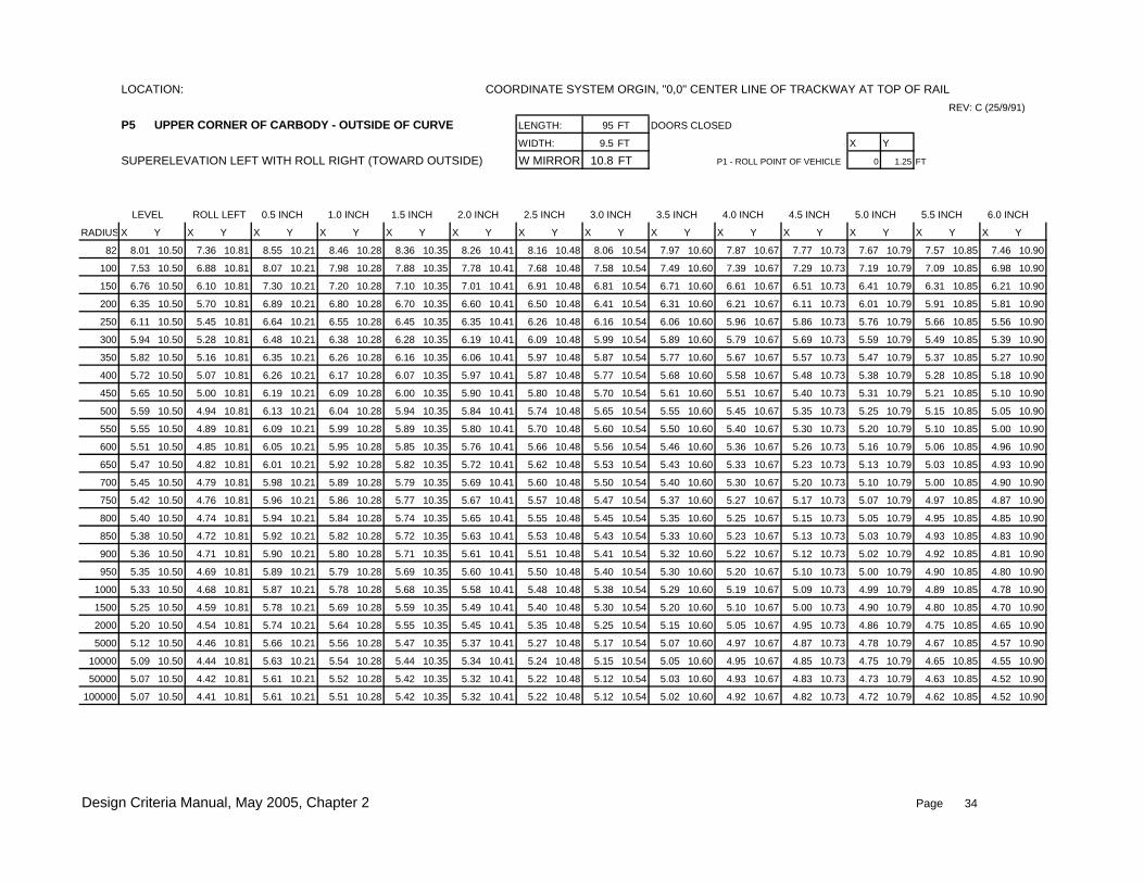
LOCATION: COORDINATE SYSTEM ORGIN, "0,0" CENTER LINE OF TRACKWAY AT TOP OF RAIL
REV: C (25/9/91)
P5 UPPER CORNER OF CARBODY - OUTSIDE OF CURVE LENGTH: 95 FT DOORS CLOSED
WIDTH: 9.5 FT X Y
SUPERELEVATION LEFT WITH ROLL RIGHT (TOWARD OUTSIDE) W MIRRORS:10.8 FT P1 - ROLL POINT OF VEHICLE 0 1.25 FT
LEVEL ROLL LEFT 0.5 INCH 1.0 INCH 1.5 INCH 2.0 INCH 2.5 INCH 3.0 INCH 3.5 INCH 4.0 INCH 4.5 INCH 5.0 INCH 5.5 INCH 6.0 INCH
RADIUS X Y X Y X Y X Y X Y X Y X Y X Y X Y X Y X Y X Y X Y X Y
82 8.01 10.50 7.36 10.81 8.55 10.21 8.46 10.28 8.36 10.35 8.26 10.41 8.16 10.48 8.06 10.54 7.97 10.60 7.87 10.67 7.77 10.73 7.67 10.79 7.57 10.85 7.46 10.90
100 7.53 10.50 6.88 10.81 8.07 10.21 7.98 10.28 7.88 10.35 7.78 10.41 7.68 10.48 7.58 10.54 7.49 10.60 7.39 10.67 7.29 10.73 7.19 10.79 7.09 10.85 6.98 10.90
150 6.76 10.50 6.10 10.81 7.30 10.21 7.20 10.28 7.10 10.35 7.01 10.41 6.91 10.48 6.81 10.54 6.71 10.60 6.61 10.67 6.51 10.73 6.41 10.79 6.31 10.85 6.21 10.90
200 6.35 10.50 5.70 10.81 6.89 10.21 6.80 10.28 6.70 10.35 6.60 10.41 6.50 10.48 6.41 10.54 6.31 10.60 6.21 10.67 6.11 10.73 6.01 10.79 5.91 10.85 5.81 10.90
250 6.11 10.50 5.45 10.81 6.64 10.21 6.55 10.28 6.45 10.35 6.35 10.41 6.26 10.48 6.16 10.54 6.06 10.60 5.96 10.67 5.86 10.73 5.76 10.79 5.66 10.85 5.56 10.90
300 5.94 10.50 5.28 10.81 6.48 10.21 6.38 10.28 6.28 10.35 6.19 10.41 6.09 10.48 5.99 10.54 5.89 10.60 5.79 10.67 5.69 10.73 5.59 10.79 5.49 10.85 5.39 10.90
350 5.82 10.50 5.16 10.81 6.35 10.21 6.26 10.28 6.16 10.35 6.06 10.41 5.97 10.48 5.87 10.54 5.77 10.60 5.67 10.67 5.57 10.73 5.47 10.79 5.37 10.85 5.27 10.90
400 5.72 10.50 5.07 10.81 6.26 10.21 6.17 10.28 6.07 10.35 5.97 10.41 5.87 10.48 5.77 10.54 5.68 10.60 5.58 10.67 5.48 10.73 5.38 10.79 5.28 10.85 5.18 10.90
450 5.65 10.50 5.00 10.81 6.19 10.21 6.09 10.28 6.00 10.35 5.90 10.41 5.80 10.48 5.70 10.54 5.61 10.60 5.51 10.67 5.40 10.73 5.31 10.79 5.21 10.85 5.10 10.90
500 5.59 10.50 4.94 10.81 6.13 10.21 6.04 10.28 5.94 10.35 5.84 10.41 5.74 10.48 5.65 10.54 5.55 10.60 5.45 10.67 5.35 10.73 5.25 10.79 5.15 10.85 5.05 10.90
550 5.55 10.50 4.89 10.81 6.09 10.21 5.99 10.28 5.89 10.35 5.80 10.41 5.70 10.48 5.60 10.54 5.50 10.60 5.40 10.67 5.30 10.73 5.20 10.79 5.10 10.85 5.00 10.90
600 5.51 10.50 4.85 10.81 6.05 10.21 5.95 10.28 5.85 10.35 5.76 10.41 5.66 10.48 5.56 10.54 5.46 10.60 5.36 10.67 5.26 10.73 5.16 10.79 5.06 10.85 4.96 10.90
650 5.47 10.50 4.82 10.81 6.01 10.21 5.92 10.28 5.82 10.35 5.72 10.41 5.62 10.48 5.53 10.54 5.43 10.60 5.33 10.67 5.23 10.73 5.13 10.79 5.03 10.85 4.93 10.90
700 5.45 10.50 4.79 10.81 5.98 10.21 5.89 10.28 5.79 10.35 5.69 10.41 5.60 10.48 5.50 10.54 5.40 10.60 5.30 10.67 5.20 10.73 5.10 10.79 5.00 10.85 4.90 10.90
750 5.42 10.50 4.76 10.81 5.96 10.21 5.86 10.28 5.77 10.35 5.67 10.41 5.57 10.48 5.47 10.54 5.37 10.60 5.27 10.67 5.17 10.73 5.07 10.79 4.97 10.85 4.87 10.90
800 5.40 10.50 4.74 10.81 5.94 10.21 5.84 10.28 5.74 10.35 5.65 10.41 5.55 10.48 5.45 10.54 5.35 10.60 5.25 10.67 5.15 10.73 5.05 10.79 4.95 10.85 4.85 10.90
850 5.38 10.50 4.72 10.81 5.92 10.21 5.82 10.28 5.72 10.35 5.63 10.41 5.53 10.48 5.43 10.54 5.33 10.60 5.23 10.67 5.13 10.73 5.03 10.79 4.93 10.85 4.83 10.90
900 5.36 10.50 4.71 10.81 5.90 10.21 5.80 10.28 5.71 10.35 5.61 10.41 5.51 10.48 5.41 10.54 5.32 10.60 5.22 10.67 5.12 10.73 5.02 10.79 4.92 10.85 4.81 10.90
950 5.35 10.50 4.69 10.81 5.89 10.21 5.79 10.28 5.69 10.35 5.60 10.41 5.50 10.48 5.40 10.54 5.30 10.60 5.20 10.67 5.10 10.73 5.00 10.79 4.90 10.85 4.80 10.90
1000 5.33 10.50 4.68 10.81 5.87 10.21 5.78 10.28 5.68 10.35 5.58 10.41 5.48 10.48 5.38 10.54 5.29 10.60 5.19 10.67 5.09 10.73 4.99 10.79 4.89 10.85 4.78 10.90
1500 5.25 10.50 4.59 10.81 5.78 10.21 5.69 10.28 5.59 10.35 5.49 10.41 5.40 10.48 5.30 10.54 5.20 10.60 5.10 10.67 5.00 10.73 4.90 10.79 4.80 10.85 4.70 10.90
2000 5.20 10.50 4.54 10.81 5.74 10.21 5.64 10.28 5.55 10.35 5.45 10.41 5.35 10.48 5.25 10.54 5.15 10.60 5.05 10.67 4.95 10.73 4.86 10.79 4.75 10.85 4.65 10.90
5000 5.12 10.50 4.46 10.81 5.66 10.21 5.56 10.28 5.47 10.35 5.37 10.41 5.27 10.48 5.17 10.54 5.07 10.60 4.97 10.67 4.87 10.73 4.78 10.79 4.67 10.85 4.57 10.90
10000 5.09 10.50 4.44 10.81 5.63 10.21 5.54 10.28 5.44 10.35 5.34 10.41 5.24 10.48 5.15 10.54 5.05 10.60 4.95 10.67 4.85 10.73 4.75 10.79 4.65 10.85 4.55 10.90
50000 5.07 10.50 4.42 10.81 5.61 10.21 5.52 10.28 5.42 10.35 5.32 10.41 5.22 10.48 5.12 10.54 5.03 10.60 4.93 10.67 4.83 10.73 4.73 10.79 4.63 10.85 4.52 10.90
100000 5.07 10.50 4.41 10.81 5.61 10.21 5.51 10.28 5.42 10.35 5.32 10.41 5.22 10.48 5.12 10.54 5.02 10.60 4.92 10.67 4.82 10.73 4.72 10.79 4.62 10.85 4.52 10.90
Design Criteria Manual, May 2005, Chapter 2 Page 34

LOCATION: COORDINATE SYSTEM ORGIN, "0,0" CENTER LINE OF TRACKWAY AT TOP OF RAIL
P6 END OF PANTOGRAPH - OUTSIDE OF CURVE REV: C (25/9/91)
PANTOGRAPH CENTERED OVER TRUCK LENGTH: 95 FT DOORS CLOSED
SUPERELEVATION LEFT WITH ROLL RIGHT (TOWARD OUTSIDE) WIDTH: 9.5 FT X Y
W MIRRORS:10.8 FT P1 - ROLL POINT OF VEHICLE 0 1.25 ft
INCLUDES .18 FT LATERAL MOTION TO OUTSIDE
LEVEL ROLL LEFT 0.5 INCH 1.0 INCH 1.5 INCH 2.0 INCH 2.5 INCH 3.0 INCH 3.5 INCH 4.0 INCH 4.5 INCH 5.0 INCH 5.5 INCH 6.0 INCH
RADIUS X Y X Y X Y X Y X Y X Y X Y X Y X Y X Y X Y X Y X Y X Y
ALL 3.56 13.25 2.71 13.45 4.26 13.05 4.14 13.11 4.02 13.16 3.90 13.21 3.78 13.26 3.65 13.32 3.53 13.37 3.41 13.41 3.28 13.46 3.16 13.51 3.03 13.55 2.91 13.60
LOCATION: COORDINATE SYSTEM ORGIN, "0,0" CENTER LINE OF TRACKWAY AT TOP OF RAIL
P7 CENTER OF PANTOGRAPH REV: C (25/9/91)
PANTOGRAPH CENTERED OVER TRUCK LENGTH: 95 FT DOORS CLOSED
SUPERELEVATION LEFT WITH ROLL RIGHT (TOWARD OUTSIDE) WIDTH: 9.5 FT X Y
SYMETRICAL WITH ROLL LEFTW MIRRORS:10.8 FT P1 - ROLL POINT OF VEHICLE 0 1.25 ft
LATERAL MOTION "+ OR -" 0.18 FT FROM CENTER
LEVEL ROLL LEFT 0.5 INCH 1.0 INCH 1.5 INCH 2.0 INCH 2.5 INCH 3.0 INCH 3.5 INCH 4.0 INCH 4.5 INCH 5.0 INCH 5.5 INCH 6.0 INCH
RADIUS X Y X Y X Y X Y X Y X Y X Y X Y X Y X Y X Y X Y X Y X Y
ALL 0.00 14.25 -0.91 14.22 0.78 14.25 0.64 14.27 0.51 14.30 0.38 14.32 0.25 14.35 0.11 14.37 -0.02 14.39 -0.15 14.41 -0.28 14.43 -0.41 14.45 -0.55 14.46 -0.68 14.48
LOCATION: COORDINATE SYSTEM ORGIN, "0,0" CENTER LINE OF TRACKWAY AT TOP OF RAIL
P8 END OF PANTOGRAPH - INSIDE OF CURVE REV: C (25/9/91)
PANTOGRAPH CENTERED OVER TRUCK LENGTH: 95 FT DOORS CLOSED
SUPERELEVATION LEFT WITH ROLL LEFT (TOWARD INSIDE) WIDTH: 9.5 FT X Y
W MIRRORS:10.8 FT P1 - ROLL POINT OF VEHICLE 0 1.25 ft
INCLUDES .18 FT LATERAL MOTION TO INSIDE
LEVEL ROLL LEFT 0.5 INCH 1.0 INCH 1.5 INCH 2.0 INCH 2.5 INCH 3.0 INCH 3.5 INCH 4.0 INCH 4.5 INCH 5.0 INCH 5.5 INCH 6.0 INCH
RADIUS X Y X Y X Y X Y X Y X Y X Y X Y X Y X Y X Y X Y X Y X Y
ALL -3.56 13.25 -4.38 12.99 -4.50 12.98 -4.62 12.96 -4.75 12.94 -4.86 12.92 -4.98 12.90 -5.10 12.88 -5.22 12.86 -5.34 12.84 -5.46 12.81 -5.58 12.79 -5.70 12.76 -5.81 12.73
Design Criteria Manual, May 2005, Chapter 2 Page 35

LOCATION: COORDINATE SYSTEM ORGIN, "0,0" CENTER LINE OF TRACKWAY AT TOP OF RAIL
REV: C (25/9/91)
P9 UPPER CORNER OF CARBODY - INSIDE OF CURVE LENGTH: 95 FT DOORS CLOSED
WIDTH: 9.5 FT X Y
SUPERELEVATION LEFT WITH ROLL LEFT (TOWARD INSIDE) W MIRRORS:10.8 FT P1 - ROLL POINT OF VEHICLE 0 1.25 FT
LEVEL ROLL LEFT 0.5 INCH 1.0 INCH 1.5 INCH 2.0 INCH 2.5 INCH 3.0 INCH 3.5 INCH 4.0 INCH 4.5 INCH 5.0 INCH 5.5 INCH 6.0 INCH
RADIUS X Y X Y X Y X Y X Y X Y X Y X Y X Y X Y X Y X Y X Y X Y
82 -6.48 10.50 -7.11 10.15 -7.21 10.12 -7.30 10.09 -7.40 10.06 -7.49 10.03 -7.59 10.00 -7.68 9.97 -7.77 9.94 -7.87 9.90 -7.96 9.87 -8.05 9.84 -8.15 9.80 -8.24 9.76
100 -6.20 10.50 -6.83 10.15 -6.93 10.12 -7.02 10.09 -7.12 10.06 -7.21 10.03 -7.30 10.00 -7.40 9.97 -7.49 9.94 -7.59 9.90 -7.68 9.87 -7.77 9.84 -7.86 9.80 -7.95 9.76
150 -5.77 10.50 -6.41 10.15 -6.50 10.12 -6.60 10.09 -6.69 10.06 -6.78 10.03 -6.88 10.00 -6.97 9.97 -7.07 9.94 -7.16 9.90 -7.25 9.87 -7.34 9.84 -7.44 9.80 -7.53 9.76
200 -5.56 10.50 -6.19 10.15 -6.29 10.12 -6.38 10.09 -6.48 10.06 -6.57 10.03 -6.67 10.00 -6.76 9.97 -6.85 9.94 -6.95 9.90 -7.04 9.87 -7.13 9.84 -7.22 9.80 -7.32 9.76
250 -5.43 10.50 -6.07 10.15 -6.16 10.12 -6.26 10.09 -6.35 10.06 -6.45 10.03 -6.54 10.00 -6.64 9.97 -6.73 9.94 -6.82 9.90 -6.92 9.87 -7.01 9.84 -7.10 9.80 -7.19 9.76
300 -5.35 10.50 -5.98 10.15 -6.08 10.12 -6.17 10.09 -6.27 10.06 -6.36 10.03 -6.46 10.00 -6.55 9.97 -6.64 9.94 -6.74 9.90 -6.83 9.87 -6.92 9.84 -7.01 9.80 -7.11 9.76
350 -5.29 10.50 -5.92 10.15 -6.02 10.12 -6.11 10.09 -6.21 10.06 -6.30 10.03 -6.40 10.00 -6.49 9.97 -6.58 9.94 -6.68 9.90 -6.77 9.87 -6.86 9.84 -6.95 9.80 -7.05 9.76
400 -5.25 10.50 -5.88 10.15 -5.97 10.12 -6.07 10.09 -6.16 10.06 -6.26 10.03 -6.35 10.00 -6.45 9.97 -6.54 9.94 -6.63 9.90 -6.73 9.87 -6.82 9.84 -6.91 9.80 -7.00 9.76
450 -5.21 10.50 -5.84 10.15 -5.94 10.12 -6.03 10.09 -6.13 10.06 -6.22 10.03 -6.32 10.00 -6.41 9.97 -6.50 9.94 -6.60 9.90 -6.69 9.87 -6.78 9.84 -6.87 9.80 -6.97 9.76
500 -5.18 10.50 -5.82 10.15 -5.91 10.12 -6.01 10.09 -6.10 10.06 -6.19 10.03 -6.29 10.00 -6.38 9.97 -6.48 9.94 -6.57 9.90 -6.66 9.87 -6.75 9.84 -6.85 9.80 -6.94 9.76
550 -5.16 10.50 -5.79 10.15 -5.89 10.12 -5.98 10.09 -6.08 10.06 -6.17 10.03 -6.27 10.00 -6.36 9.97 -6.45 9.94 -6.55 9.90 -6.64 9.87 -6.73 9.84 -6.82 9.80 -6.91 9.76
600 -5.14 10.50 -5.77 10.15 -5.87 10.12 -5.96 10.09 -6.06 10.06 -6.15 10.03 -6.25 10.00 -6.34 9.97 -6.43 9.94 -6.53 9.90 -6.62 9.87 -6.71 9.84 -6.80 9.80 -6.90 9.76
650 -5.12 10.50 -5.76 10.15 -5.85 10.12 -5.95 10.09 -6.04 10.06 -6.14 10.03 -6.23 10.00 -6.33 9.97 -6.42 9.94 -6.51 9.90 -6.60 9.87 -6.70 9.84 -6.79 9.80 -6.88 9.76
700 -5.11 10.50 -5.74 10.15 -5.84 10.12 -5.93 10.09 -6.03 10.06 -6.12 10.03 -6.22 10.00 -6.31 9.97 -6.40 9.94 -6.50 9.90 -6.59 9.87 -6.68 9.84 -6.77 9.80 -6.87 9.76
750 -5.10 10.50 -5.73 10.15 -5.83 10.12 -5.92 10.09 -6.02 10.06 -6.11 10.03 -6.20 10.00 -6.30 9.97 -6.39 9.94 -6.49 9.90 -6.58 9.87 -6.67 9.84 -6.76 9.80 -6.85 9.76
800 -5.09 10.50 -5.72 10.15 -5.82 10.12 -5.91 10.09 -6.01 10.06 -6.10 10.03 -6.19 10.00 -6.29 9.97 -6.38 9.94 -6.47 9.90 -6.57 9.87 -6.66 9.84 -6.75 9.80 -6.84 9.76
850 -5.08 10.50 -5.71 10.15 -5.81 10.12 -5.90 10.09 -6.00 10.06 -6.09 10.03 -6.18 10.00 -6.28 9.97 -6.37 9.94 -6.47 9.90 -6.56 9.87 -6.65 9.84 -6.74 9.80 -6.83 9.76
900 -5.07 10.50 -5.70 10.15 -5.80 10.12 -5.89 10.09 -5.99 10.06 -6.08 10.03 -6.18 10.00 -6.27 9.97 -6.36 9.94 -6.46 9.90 -6.55 9.87 -6.64 9.84 -6.73 9.80 -6.83 9.76
950 -5.06 10.50 -5.70 10.15 -5.79 10.12 -5.89 10.09 -5.98 10.06 -6.07 10.03 -6.17 10.00 -6.26 9.97 -6.36 9.94 -6.45 9.90 -6.54 9.87 -6.63 9.84 -6.73 9.80 -6.82 9.76
1000 -5.06 10.50 -5.69 10.15 -5.78 10.12 -5.88 10.09 -5.97 10.06 -6.07 10.03 -6.16 10.00 -6.26 9.97 -6.35 9.94 -6.44 9.90 -6.54 9.87 -6.63 9.84 -6.72 9.80 -6.81 9.76
1500 -5.01 10.50 -5.65 10.15 -5.74 10.12 -5.84 10.09 -5.93 10.06 -6.03 10.03 -6.12 10.00 -6.22 9.97 -6.31 9.94 -6.40 9.90 -6.49 9.87 -6.59 9.84 -6.68 9.80 -6.77 9.76
2000 -4.99 10.50 -5.63 10.15 -5.72 10.12 -5.82 10.09 -5.91 10.06 -6.00 10.03 -6.10 10.00 -6.19 9.97 -6.29 9.94 -6.38 9.90 -6.47 9.87 -6.56 9.84 -6.66 9.80 -6.75 9.76
5000 -5.01 10.50 -5.65 10.15 -5.74 10.12 -5.84 10.09 -5.93 10.06 -6.03 10.03 -6.12 10.00 -6.22 9.97 -6.31 9.94 -6.40 9.90 -6.49 9.87 -6.59 9.84 -6.68 9.80 -6.77 9.76
10000 -5.04 10.50 -5.67 10.15 -5.77 10.12 -5.86 10.09 -5.96 10.06 -6.05 10.03 -6.15 10.00 -6.24 9.97 -6.33 9.94 -6.43 9.90 -6.52 9.87 -6.61 9.84 -6.70 9.80 -6.80 9.76
50000 -5.06 10.50 -5.70 10.15 -5.79 10.12 -5.89 10.09 -5.98 10.06 -6.07 10.03 -6.17 10.00 -6.26 9.97 -6.36 9.94 -6.45 9.90 -6.54 9.87 -6.63 9.84 -6.73 9.80 -6.82 9.76
100000 -5.07 10.50 -5.70 10.15 -5.79 10.12 -5.89 10.09 -5.98 10.06 -6.08 10.03 -6.17 10.00 -6.27 9.97 -6.36 9.94 -6.45 9.90 -6.55 9.87 -6.64 9.84 -6.73 9.80 -6.82 9.76
Design Criteria Manual, May 2005, Chapter 2 Page 36

LOCATION: COORDINATE SYSTEM ORGIN, "0,0" CENTER LINE OF TRACKWAY AT TOP OF RAIL
REV: C (25/9/91)
P10 UPPER CORNER OF MIRROR - INSIDE OF CURVE LENGTH: 95 FT DOORS CLOSED
WIDTH: 9.5 FT X Y
SUPERELEVATION LEFT WITH ROLL LEFT (TOWARD INSIDE) W MIRRORS:10.8 FT P1 - ROLL POINT OF VEHICLE 0 1.25 FT
LEVEL ROLL LEFT 0.5 INCH 1.0 INCH 1.5 INCH 2.0 INCH 2.5 INCH 3.0 INCH 3.5 INCH 4.0 INCH 4.5 INCH 5.0 INCH 5.5 INCH 6.0 INCH
RADIUS X Y X Y X Y X Y X Y X Y X Y X Y X Y X Y X Y X Y X Y X Y
82 -6.48 9.80 -7.06 9.40 -7.15 9.37 -7.24 9.34 -7.33 9.30 -7.42 9.27 -7.50 9.23 -7.59 9.19 -7.68 9.16 -7.76 9.12 -7.85 9.08 -7.93 9.04 -8.02 9.00 -8.10 8.96
100 -6.20 9.80 -6.78 9.40 -6.87 9.37 -6.96 9.34 -7.05 9.30 -7.13 9.27 -7.22 9.23 -7.31 9.19 -7.39 9.16 -7.48 9.12 -7.57 9.08 -7.65 9.04 -7.74 9.00 -7.82 8.96
150 -5.77 9.80 -6.36 9.40 -6.44 9.37 -6.53 9.34 -6.62 9.30 -6.71 9.27 -6.80 9.23 -6.88 9.19 -6.97 9.16 -7.05 9.12 -7.14 9.08 -7.23 9.04 -7.31 9.00 -7.40 8.96
200 -5.56 9.80 -6.14 9.40 -6.23 9.37 -6.32 9.34 -6.41 9.30 -6.50 9.27 -6.58 9.23 -6.67 9.19 -6.76 9.16 -6.84 9.12 -6.93 9.08 -7.01 9.04 -7.10 9.00 -7.18 8.96
250 -5.43 9.80 -6.02 9.40 -6.11 9.37 -6.19 9.34 -6.28 9.30 -6.37 9.27 -6.46 9.23 -6.54 9.19 -6.63 9.16 -6.72 9.12 -6.80 9.08 -6.89 9.04 -6.97 9.00 -7.06 8.96
300 -5.35 9.80 -5.93 9.40 -6.02 9.37 -6.11 9.34 -6.20 9.30 -6.28 9.27 -6.37 9.23 -6.46 9.19 -6.55 9.16 -6.63 9.12 -6.72 9.08 -6.80 9.04 -6.89 9.00 -6.97 8.96
350 -5.29 9.80 -5.87 9.40 -5.96 9.37 -6.05 9.34 -6.14 9.30 -6.22 9.27 -6.31 9.23 -6.40 9.19 -6.49 9.16 -6.57 9.12 -6.66 9.08 -6.74 9.04 -6.83 9.00 -6.91 8.96
400 -5.25 9.80 -5.83 9.40 -5.92 9.37 -6.00 9.34 -6.09 9.30 -6.18 9.27 -6.27 9.23 -6.36 9.19 -6.44 9.16 -6.53 9.12 -6.61 9.08 -6.70 9.04 -6.78 9.00 -6.87 8.96
450 -5.21 9.80 -5.79 9.40 -5.88 9.37 -5.97 9.34 -6.06 9.30 -6.14 9.27 -6.23 9.23 -6.32 9.19 -6.41 9.16 -6.49 9.12 -6.58 9.08 -6.66 9.04 -6.75 9.00 -6.83 8.96
500 -5.18 9.80 -5.77 9.40 -5.85 9.37 -5.94 9.34 -6.03 9.30 -6.12 9.27 -6.20 9.23 -6.29 9.19 -6.38 9.16 -6.46 9.12 -6.55 9.08 -6.63 9.04 -6.72 9.00 -6.81 8.96
550 -5.16 9.80 -5.74 9.40 -5.83 9.37 -5.92 9.34 -6.01 9.30 -6.09 9.27 -6.18 9.23 -6.27 9.19 -6.35 9.16 -6.44 9.12 -6.53 9.08 -6.61 9.04 -6.70 9.00 -6.78 8.96
600 -5.14 9.80 -5.73 9.40 -5.81 9.37 -5.90 9.34 -5.99 9.30 -6.08 9.27 -6.17 9.23 -6.25 9.19 -6.34 9.16 -6.43 9.12 -6.51 9.08 -6.60 9.04 -6.68 9.00 -6.77 8.96
650 -5.19 9.80 -5.78 9.40 -5.86 9.37 -5.95 9.34 -6.04 9.30 -6.13 9.27 -6.22 9.23 -6.30 9.19 -6.39 9.16 -6.47 9.12 -6.56 9.08 -6.64 9.04 -6.73 9.00 -6.82 8.96
700 -5.23 9.80 -5.82 9.40 -5.91 9.37 -5.99 9.34 -6.08 9.30 -6.17 9.27 -6.26 9.23 -6.34 9.19 -6.43 9.16 -6.52 9.12 -6.60 9.08 -6.69 9.04 -6.77 9.00 -6.86 8.96
750 -5.27 9.80 -5.85 9.40 -5.94 9.37 -6.03 9.34 -6.12 9.30 -6.21 9.27 -6.29 9.23 -6.38 9.19 -6.47 9.16 -6.55 9.12 -6.64 9.08 -6.72 9.04 -6.81 9.00 -6.89 8.96
800 -5.30 9.80 -5.89 9.40 -5.97 9.37 -6.06 9.34 -6.15 9.30 -6.24 9.27 -6.32 9.23 -6.41 9.19 -6.50 9.16 -6.58 9.12 -6.67 9.08 -6.75 9.04 -6.84 9.00 -6.93 8.96
850 -5.33 9.80 -5.91 9.40 -6.00 9.37 -6.09 9.34 -6.18 9.30 -6.26 9.27 -6.35 9.23 -6.44 9.19 -6.53 9.16 -6.61 9.12 -6.70 9.08 -6.78 9.04 -6.87 9.00 -6.95 8.96
900 -5.35 9.80 -5.94 9.40 -6.03 9.37 -6.11 9.34 -6.20 9.30 -6.29 9.27 -6.38 9.23 -6.47 9.19 -6.55 9.16 -6.64 9.12 -6.72 9.08 -6.81 9.04 -6.89 9.00 -6.98 8.96
950 -5.38 9.80 -5.96 9.40 -6.05 9.37 -6.14 9.34 -6.23 9.30 -6.31 9.27 -6.40 9.23 -6.49 9.19 -6.57 9.16 -6.66 9.12 -6.75 9.08 -6.83 9.04 -6.92 9.00 -7.00 8.96
1000 -5.40 9.80 -5.98 9.40 -6.07 9.37 -6.16 9.34 -6.25 9.30 -6.33 9.27 -6.42 9.23 -6.51 9.19 -6.59 9.16 -6.68 9.12 -6.77 9.08 -6.85 9.04 -6.94 9.00 -7.02 8.96
1500 -5.52 9.80 -6.11 9.40 -6.19 9.37 -6.28 9.34 -6.37 9.30 -6.46 9.27 -6.55 9.23 -6.63 9.19 -6.72 9.16 -6.81 9.12 -6.89 9.08 -6.98 9.04 -7.06 9.00 -7.15 8.96
2000 -5.59 9.80 -6.17 9.40 -6.26 9.37 -6.35 9.34 -6.43 9.30 -6.52 9.27 -6.61 9.23 -6.70 9.19 -6.78 9.16 -6.87 9.12 -6.95 9.08 -7.04 9.04 -7.12 9.00 -7.21 8.96
5000 -5.70 9.80 -6.28 9.40 -6.37 9.37 -6.46 9.34 -6.55 9.30 -6.63 9.27 -6.72 9.23 -6.81 9.19 -6.89 9.16 -6.98 9.12 -7.07 9.08 -7.15 9.04 -7.24 9.00 -7.32 8.96
10000 -5.74 9.80 -6.32 9.40 -6.41 9.37 -6.50 9.34 -6.58 9.30 -6.67 9.27 -6.76 9.23 -6.85 9.19 -6.93 9.16 -7.02 9.12 -7.10 9.08 -7.19 9.04 -7.27 9.00 -7.36 8.96
50000 -5.77 9.80 -6.35 9.40 -6.44 9.37 -6.53 9.34 -6.61 9.30 -6.70 9.27 -6.79 9.23 -6.88 9.19 -6.96 9.16 -7.05 9.12 -7.13 9.08 -7.22 9.04 -7.30 9.00 -7.39 8.96
100000 -5.77 9.80 -6.35 9.40 -6.44 9.37 -6.53 9.34 -6.62 9.30 -6.70 9.27 -6.79 9.23 -6.88 9.19 -6.97 9.16 -7.05 9.12 -7.14 9.08 -7.22 9.04 -7.31 9.00 -7.39 8.96
Design Criteria Manual, May 2005, Chapter 2 Page 37
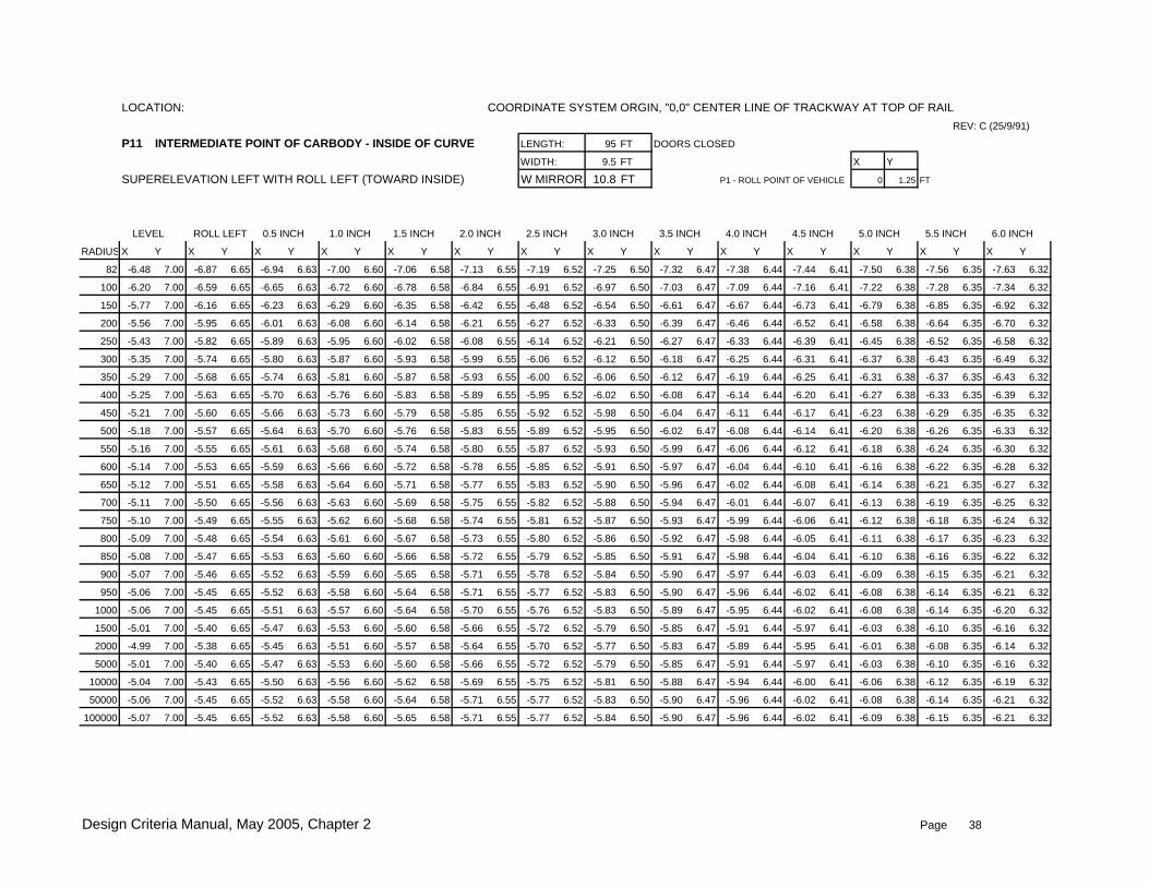
LOCATION: COORDINATE SYSTEM ORGIN, "0,0" CENTER LINE OF TRACKWAY AT TOP OF RAIL
REV: C (25/9/91)
P11 INTERMEDIATE POINT OF CARBODY - INSIDE OF CURVE LENGTH: 95 FT DOORS CLOSED
WIDTH: 9.5 FT X Y
SUPERELEVATION LEFT WITH ROLL LEFT (TOWARD INSIDE) W MIRRORS:10.8 FT P1 - ROLL POINT OF VEHICLE 0 1.25 FT
LEVEL ROLL LEFT 0.5 INCH 1.0 INCH 1.5 INCH 2.0 INCH 2.5 INCH 3.0 INCH 3.5 INCH 4.0 INCH 4.5 INCH 5.0 INCH 5.5 INCH 6.0 INCH
RADIUS X Y X Y X Y X Y X Y X Y X Y X Y X Y X Y X Y X Y X Y X Y
82 -6.48 7.00 -6.87 6.65 -6.94 6.63 -7.00 6.60 -7.06 6.58 -7.13 6.55 -7.19 6.52 -7.25 6.50 -7.32 6.47 -7.38 6.44 -7.44 6.41 -7.50 6.38 -7.56 6.35 -7.63 6.32
100 -6.20 7.00 -6.59 6.65 -6.65 6.63 -6.72 6.60 -6.78 6.58 -6.84 6.55 -6.91 6.52 -6.97 6.50 -7.03 6.47 -7.09 6.44 -7.16 6.41 -7.22 6.38 -7.28 6.35 -7.34 6.32
150 -5.77 7.00 -6.16 6.65 -6.23 6.63 -6.29 6.60 -6.35 6.58 -6.42 6.55 -6.48 6.52 -6.54 6.50 -6.61 6.47 -6.67 6.44 -6.73 6.41 -6.79 6.38 -6.85 6.35 -6.92 6.32
200 -5.56 7.00 -5.95 6.65 -6.01 6.63 -6.08 6.60 -6.14 6.58 -6.21 6.55 -6.27 6.52 -6.33 6.50 -6.39 6.47 -6.46 6.44 -6.52 6.41 -6.58 6.38 -6.64 6.35 -6.70 6.32
250 -5.43 7.00 -5.82 6.65 -5.89 6.63 -5.95 6.60 -6.02 6.58 -6.08 6.55 -6.14 6.52 -6.21 6.50 -6.27 6.47 -6.33 6.44 -6.39 6.41 -6.45 6.38 -6.52 6.35 -6.58 6.32
300 -5.35 7.00 -5.74 6.65 -5.80 6.63 -5.87 6.60 -5.93 6.58 -5.99 6.55 -6.06 6.52 -6.12 6.50 -6.18 6.47 -6.25 6.44 -6.31 6.41 -6.37 6.38 -6.43 6.35 -6.49 6.32
350 -5.29 7.00 -5.68 6.65 -5.74 6.63 -5.81 6.60 -5.87 6.58 -5.93 6.55 -6.00 6.52 -6.06 6.50 -6.12 6.47 -6.19 6.44 -6.25 6.41 -6.31 6.38 -6.37 6.35 -6.43 6.32
400 -5.25 7.00 -5.63 6.65 -5.70 6.63 -5.76 6.60 -5.83 6.58 -5.89 6.55 -5.95 6.52 -6.02 6.50 -6.08 6.47 -6.14 6.44 -6.20 6.41 -6.27 6.38 -6.33 6.35 -6.39 6.32
450 -5.21 7.00 -5.60 6.65 -5.66 6.63 -5.73 6.60 -5.79 6.58 -5.85 6.55 -5.92 6.52 -5.98 6.50 -6.04 6.47 -6.11 6.44 -6.17 6.41 -6.23 6.38 -6.29 6.35 -6.35 6.32
500 -5.18 7.00 -5.57 6.65 -5.64 6.63 -5.70 6.60 -5.76 6.58 -5.83 6.55 -5.89 6.52 -5.95 6.50 -6.02 6.47 -6.08 6.44 -6.14 6.41 -6.20 6.38 -6.26 6.35 -6.33 6.32
550 -5.16 7.00 -5.55 6.65 -5.61 6.63 -5.68 6.60 -5.74 6.58 -5.80 6.55 -5.87 6.52 -5.93 6.50 -5.99 6.47 -6.06 6.44 -6.12 6.41 -6.18 6.38 -6.24 6.35 -6.30 6.32
600 -5.14 7.00 -5.53 6.65 -5.59 6.63 -5.66 6.60 -5.72 6.58 -5.78 6.55 -5.85 6.52 -5.91 6.50 -5.97 6.47 -6.04 6.44 -6.10 6.41 -6.16 6.38 -6.22 6.35 -6.28 6.32
650 -5.12 7.00 -5.51 6.65 -5.58 6.63 -5.64 6.60 -5.71 6.58 -5.77 6.55 -5.83 6.52 -5.90 6.50 -5.96 6.47 -6.02 6.44 -6.08 6.41 -6.14 6.38 -6.21 6.35 -6.27 6.32
700 -5.11 7.00 -5.50 6.65 -5.56 6.63 -5.63 6.60 -5.69 6.58 -5.75 6.55 -5.82 6.52 -5.88 6.50 -5.94 6.47 -6.01 6.44 -6.07 6.41 -6.13 6.38 -6.19 6.35 -6.25 6.32
750 -5.10 7.00 -5.49 6.65 -5.55 6.63 -5.62 6.60 -5.68 6.58 -5.74 6.55 -5.81 6.52 -5.87 6.50 -5.93 6.47 -5.99 6.44 -6.06 6.41 -6.12 6.38 -6.18 6.35 -6.24 6.32
800 -5.09 7.00 -5.48 6.65 -5.54 6.63 -5.61 6.60 -5.67 6.58 -5.73 6.55 -5.80 6.52 -5.86 6.50 -5.92 6.47 -5.98 6.44 -6.05 6.41 -6.11 6.38 -6.17 6.35 -6.23 6.32
850 -5.08 7.00 -5.47 6.65 -5.53 6.63 -5.60 6.60 -5.66 6.58 -5.72 6.55 -5.79 6.52 -5.85 6.50 -5.91 6.47 -5.98 6.44 -6.04 6.41 -6.10 6.38 -6.16 6.35 -6.22 6.32
900 -5.07 7.00 -5.46 6.65 -5.52 6.63 -5.59 6.60 -5.65 6.58 -5.71 6.55 -5.78 6.52 -5.84 6.50 -5.90 6.47 -5.97 6.44 -6.03 6.41 -6.09 6.38 -6.15 6.35 -6.21 6.32
950 -5.06 7.00 -5.45 6.65 -5.52 6.63 -5.58 6.60 -5.64 6.58 -5.71 6.55 -5.77 6.52 -5.83 6.50 -5.90 6.47 -5.96 6.44 -6.02 6.41 -6.08 6.38 -6.14 6.35 -6.21 6.32
1000 -5.06 7.00 -5.45 6.65 -5.51 6.63 -5.57 6.60 -5.64 6.58 -5.70 6.55 -5.76 6.52 -5.83 6.50 -5.89 6.47 -5.95 6.44 -6.02 6.41 -6.08 6.38 -6.14 6.35 -6.20 6.32
1500 -5.01 7.00 -5.40 6.65 -5.47 6.63 -5.53 6.60 -5.60 6.58 -5.66 6.55 -5.72 6.52 -5.79 6.50 -5.85 6.47 -5.91 6.44 -5.97 6.41 -6.03 6.38 -6.10 6.35 -6.16 6.32
2000 -4.99 7.00 -5.38 6.65 -5.45 6.63 -5.51 6.60 -5.57 6.58 -5.64 6.55 -5.70 6.52 -5.77 6.50 -5.83 6.47 -5.89 6.44 -5.95 6.41 -6.01 6.38 -6.08 6.35 -6.14 6.32
5000 -5.01 7.00 -5.40 6.65 -5.47 6.63 -5.53 6.60 -5.60 6.58 -5.66 6.55 -5.72 6.52 -5.79 6.50 -5.85 6.47 -5.91 6.44 -5.97 6.41 -6.03 6.38 -6.10 6.35 -6.16 6.32
10000 -5.04 7.00 -5.43 6.65 -5.50 6.63 -5.56 6.60 -5.62 6.58 -5.69 6.55 -5.75 6.52 -5.81 6.50 -5.88 6.47 -5.94 6.44 -6.00 6.41 -6.06 6.38 -6.12 6.35 -6.19 6.32
50000 -5.06 7.00 -5.45 6.65 -5.52 6.63 -5.58 6.60 -5.64 6.58 -5.71 6.55 -5.77 6.52 -5.83 6.50 -5.90 6.47 -5.96 6.44 -6.02 6.41 -6.08 6.38 -6.14 6.35 -6.21 6.32
100000 -5.07 7.00 -5.45 6.65 -5.52 6.63 -5.58 6.60 -5.65 6.58 -5.71 6.55 -5.77 6.52 -5.84 6.50 -5.90 6.47 -5.96 6.44 -6.02 6.41 -6.09 6.38 -6.15 6.35 -6.21 6.32
Design Criteria Manual, May 2005, Chapter 2 Page 38

LOCATION: COORDINATE SYSTEM ORGIN, "0,0" CENTER LINE OF TRACKWAY AT TOP OF RAIL
REV: C (25/9/91)
P12 LOWER CORNER OF CARBODY - INSIDE OF CURVE LENGTH: 95 FT DOORS CLOSED
WIDTH: 9.5 FT X Y
SUPERELEVATION LEFT WITH ROLL RIGHT (TOWARD OUTSIDE) W MIRRORS:10.8 FT P1 - ROLL POINT OF VEHICLE 0 1.25 FT
LEVEL ROLL LEFT 0.5 INCH 1.0 INCH 1.5 INCH 2.0 INCH 2.5 INCH 3.0 INCH 3.5 INCH 4.0 INCH 4.5 INCH 5.0 INCH 5.5 INCH 6.0 INCH
RADIUS X Y X Y X Y X Y X Y X Y X Y X Y X Y X Y X Y X Y X Y X Y
82 -6.48 0.67 -6.43 0.72 -6.52 0.98 -6.54 0.96 -6.55 0.94 -6.57 0.92 -6.58 0.89 -6.59 0.87 -6.61 0.85 -6.62 0.83 -6.63 0.80 -6.64 0.78 -6.66 0.76 -6.67 0.74
100 -6.20 0.67 -6.15 0.72 -6.24 0.98 -6.26 0.96 -6.27 0.94 -6.28 0.92 -6.30 0.89 -6.31 0.87 -6.32 0.85 -6.34 0.83 -6.35 0.80 -6.36 0.78 -6.37 0.76 -6.39 0.74
150 -5.77 0.67 -5.72 0.72 -5.82 0.98 -5.83 0.96 -5.84 0.94 -5.86 0.92 -5.87 0.89 -5.88 0.87 -5.90 0.85 -5.91 0.83 -5.92 0.80 -5.94 0.78 -5.95 0.76 -5.96 0.74
200 -5.56 0.67 -5.51 0.72 -5.60 0.98 -5.62 0.96 -5.63 0.94 -5.65 0.92 -5.66 0.89 -5.67 0.87 -5.69 0.85 -5.70 0.83 -5.71 0.80 -5.72 0.78 -5.74 0.76 -5.75 0.74
250 -5.43 0.67 -5.38 0.72 -5.48 0.98 -5.49 0.96 -5.51 0.94 -5.52 0.92 -5.53 0.89 -5.55 0.87 -5.56 0.85 -5.57 0.83 -5.59 0.80 -5.60 0.78 -5.61 0.76 -5.62 0.74
300 -5.35 0.67 -5.30 0.72 -5.39 0.98 -5.41 0.96 -5.42 0.94 -5.44 0.92 -5.45 0.89 -5.46 0.87 -5.48 0.85 -5.49 0.83 -5.50 0.80 -5.51 0.78 -5.53 0.76 -5.54 0.74
350 -5.29 0.67 -5.24 0.72 -5.33 0.98 -5.35 0.96 -5.36 0.94 -5.38 0.92 -5.39 0.89 -5.40 0.87 -5.42 0.85 -5.43 0.83 -5.44 0.80 -5.45 0.78 -5.47 0.76 -5.48 0.74
400 -5.25 0.67 -5.19 0.72 -5.29 0.98 -5.30 0.96 -5.32 0.94 -5.33 0.92 -5.34 0.89 -5.36 0.87 -5.37 0.85 -5.38 0.83 -5.40 0.80 -5.41 0.78 -5.42 0.76 -5.43 0.74
450 -5.21 0.67 -5.16 0.72 -5.25 0.98 -5.27 0.96 -5.28 0.94 -5.29 0.92 -5.31 0.89 -5.32 0.87 -5.33 0.85 -5.35 0.83 -5.36 0.80 -5.37 0.78 -5.39 0.76 -5.40 0.74
500 -5.18 0.67 -5.13 0.72 -5.23 0.98 -5.24 0.96 -5.25 0.94 -5.27 0.92 -5.28 0.89 -5.29 0.87 -5.31 0.85 -5.32 0.83 -5.33 0.80 -5.34 0.78 -5.36 0.76 -5.37 0.74
550 -5.16 0.67 -5.11 0.72 -5.20 0.98 -5.22 0.96 -5.23 0.94 -5.24 0.92 -5.26 0.89 -5.27 0.87 -5.28 0.85 -5.30 0.83 -5.31 0.80 -5.32 0.78 -5.33 0.76 -5.35 0.74
600 -5.14 0.67 -5.09 0.72 -5.18 0.98 -5.20 0.96 -5.21 0.94 -5.22 0.92 -5.24 0.89 -5.25 0.87 -5.26 0.85 -5.28 0.83 -5.29 0.80 -5.30 0.78 -5.32 0.76 -5.33 0.74
650 -5.12 0.67 -5.07 0.72 -5.17 0.98 -5.18 0.96 -5.20 0.94 -5.21 0.92 -5.22 0.89 -5.24 0.87 -5.25 0.85 -5.26 0.83 -5.27 0.80 -5.29 0.78 -5.30 0.76 -5.31 0.74
700 -5.11 0.67 -5.06 0.72 -5.15 0.98 -5.17 0.96 -5.18 0.94 -5.19 0.92 -5.21 0.89 -5.22 0.87 -5.23 0.85 -5.25 0.83 -5.26 0.80 -5.27 0.78 -5.29 0.76 -5.30 0.74
750 -5.10 0.67 -5.05 0.72 -5.14 0.98 -5.16 0.96 -5.17 0.94 -5.18 0.92 -5.20 0.89 -5.21 0.87 -5.22 0.85 -5.24 0.83 -5.25 0.80 -5.26 0.78 -5.27 0.76 -5.29 0.74
800 -5.09 0.67 -5.04 0.72 -5.13 0.98 -5.14 0.96 -5.16 0.94 -5.17 0.92 -5.19 0.89 -5.20 0.87 -5.21 0.85 -5.23 0.83 -5.24 0.80 -5.25 0.78 -5.26 0.76 -5.27 0.74
850 -5.08 0.67 -5.03 0.72 -5.12 0.98 -5.14 0.96 -5.15 0.94 -5.16 0.92 -5.18 0.89 -5.19 0.87 -5.20 0.85 -5.22 0.83 -5.23 0.80 -5.24 0.78 -5.25 0.76 -5.27 0.74
900 -5.07 0.67 -5.02 0.72 -5.11 0.98 -5.13 0.96 -5.14 0.94 -5.15 0.92 -5.17 0.89 -5.18 0.87 -5.19 0.85 -5.21 0.83 -5.22 0.80 -5.23 0.78 -5.25 0.76 -5.26 0.74
950 -5.06 0.67 -5.01 0.72 -5.11 0.98 -5.12 0.96 -5.13 0.94 -5.15 0.92 -5.16 0.89 -5.17 0.87 -5.19 0.85 -5.20 0.83 -5.21 0.80 -5.23 0.78 -5.24 0.76 -5.25 0.74
1000 -5.06 0.67 -5.00 0.72 -5.10 0.98 -5.11 0.96 -5.13 0.94 -5.14 0.92 -5.15 0.89 -5.17 0.87 -5.18 0.85 -5.19 0.83 -5.21 0.80 -5.22 0.78 -5.23 0.76 -5.24 0.74
1500 -5.01 0.67 -4.96 0.72 -5.06 0.98 -5.07 0.96 -5.09 0.94 -5.10 0.92 -5.11 0.89 -5.13 0.87 -5.14 0.85 -5.15 0.83 -5.16 0.80 -5.18 0.78 -5.19 0.76 -5.20 0.74
2000 -4.99 0.67 -4.94 0.72 -5.04 0.98 -5.05 0.96 -5.06 0.94 -5.08 0.92 -5.09 0.89 -5.10 0.87 -5.12 0.85 -5.13 0.83 -5.14 0.80 -5.16 0.78 -5.17 0.76 -5.18 0.74
5000 -5.01 0.67 -4.96 0.72 -5.06 0.98 -5.07 0.96 -5.09 0.94 -5.10 0.92 -5.11 0.89 -5.13 0.87 -5.14 0.85 -5.15 0.83 -5.17 0.80 -5.18 0.78 -5.19 0.76 -5.20 0.74
10000 -5.04 0.67 -4.99 0.72 -5.08 0.98 -5.10 0.96 -5.11 0.94 -5.13 0.92 -5.14 0.89 -5.15 0.87 -5.17 0.85 -5.18 0.83 -5.19 0.80 -5.20 0.78 -5.22 0.76 -5.23 0.74
50000 -5.06 0.67 -5.01 0.72 -5.11 0.98 -5.12 0.96 -5.13 0.94 -5.15 0.92 -5.16 0.89 -5.17 0.87 -5.19 0.85 -5.20 0.83 -5.21 0.80 -5.23 0.78 -5.24 0.76 -5.25 0.74
100000 -5.07 0.67 -5.01 0.72 -5.11 0.98 -5.12 0.96 -5.14 0.94 -5.15 0.92 -5.16 0.89 -5.18 0.87 -5.19 0.85 -5.20 0.83 -5.22 0.80 -5.23 0.78 -5.24 0.76 -5.25 0.74
Design Criteria Manual, May 2005, Chapter 2 Page 39

LOCATION: COORDINATE SYSTEM ORGIN, "0,0" CENTER LINE OF TRACKWAY AT TOP OF RAIL
P13 INTERMEDIATE POINT OF PANTOGRAPH - OUTSIDE OF CURVE REV: C (25/9/91)
PANTOGRAPH CENTERED OVER TRUCK LENGTH: 95 FT DOORS CLOSED
SUPERELEVATION LEFT WITH ROLL RIGHT (TOWARD OUTSIDE) WIDTH: 9.5 FT X Y
W MIRRORS:10.8 FT P1 - ROLL POINT OF VEHICLE 0 1.25 ft
INCLUDES .18 FT LATERAL MOTION TO OUTSIDE
LEVEL ROLL LEFT 0.5 INCH 1.0 INCH 1.5 INCH 2.0 INCH 2.5 INCH 3.0 INCH 3.5 INCH 4.0 INCH 4.5 INCH 5.0 INCH 5.5 INCH 6.0 INCH
RADIUS X Y X Y X Y X Y X Y X Y X Y X Y X Y X Y X Y X Y X Y X Y
ALL 2.56 14.25 1.64 14.39 3.33 14.09 3.20 14.14 3.06 14.19 2.93 14.24 2.80 14.28 2.67 14.33 2.54 14.37 2.40 14.41 2.27 14.45 2.14 14.49 2.01 14.53 1.87 14.57
LOCATION: COORDINATE SYSTEM ORGIN, "0,0" CENTER LINE OF TRACKWAY AT TOP OF RAIL
P14 INTERMEDIATE POINT OF PANTOGRAPH - INSIDE OF CURVE REV: C (25/9/91)
PANTOGRAPH CENTERED OVER TRUCK LENGTH: 95 FT DOORS CLOSED
SUPERELEVATION LEFT WITH ROLL LEFT (TOWARD INSIDE) WIDTH: 9.5 FT X Y
W MIRRORS:10.8 FT P1 - ROLL POINT OF VEHICLE 0 1.25 ft
INCLUDES .18 FT OF LATERAL MOTION
LEVEL ROLL LEFT 0.5 INCH 1.0 INCH 1.5 INCH 2.0 INCH 2.5 INCH 3.0 INCH 3.5 INCH 4.0 INCH 4.5 INCH 5.0 INCH 5.5 INCH 6.0 INCH
RADIUS X Y X Y X Y X Y X Y X Y X Y X Y X Y X Y X Y X Y X Y X Y
ALL -2.56 14.25 -3.46 14.04 -3.59 14.03 -3.71 14.02 -3.85 14.01 -3.97 14.00 -4.10 13.98 -4.23 13.97 -4.36 13.95 -4.49 13.93 -4.62 13.91 -4.74 13.89 -4.87 13.87 -5.00 13.85
LOCATION: COORDINATE SYSTEM ORGIN, "0,0" CENTER LINE OF TRACKWAY AT TOP OF RAIL
P15 END OF PANTOGRAPH - OUTSIDE OF CURVE REV: C (25/9/91)
PANTOGRAPH CENTERED OVER TRUCK LENGTH: 95 FT DOORS CLOSED
SUPERELEVATION LEFT WITH ROLL RIGHT (TOWARD OUTSIDE) WIDTH: 9.5 FT X Y
W MIRRORS:10.8 FT P1 - ROLL POINT OF VEHICLE 0 1.25 ft
INCLUDES .18 FT LATERAL MOTION TO OUTSIDE
LEVEL ROLL LEFT 0.5 INCH 1.0 INCH 1.5 INCH 2.0 INCH 2.5 INCH 3.0 INCH 3.5 INCH 4.0 INCH 4.5 INCH 5.0 INCH 5.5 INCH 6.0 INCH
RADIUS X Y X Y X Y X Y X Y X Y X Y X Y X Y X Y X Y X Y X Y X Y
ALL 3.56 17.00 2.45 17.19 4.49 16.79 4.34 16.85 4.18 16.91 4.03 16.96 3.87 17.01 3.71 17.07 3.56 17.12 3.40 17.16 3.24 17.21 3.09 17.26 2.93 17.30 2.77 17.35
Design Criteria Manual, May 2005, Chapter 2 Page 40

LOCATION: COORDINATE SYSTEM ORGIN, "0,0" CENTER LINE OF TRACKWAY AT TOP OF RAIL
P16 INTERMEDIATE POINT OF PANTOGRAPH - OUTSIDE OF CURVE REV: C (25/9/91)
PANTOGRAPH CENTERED OVER TRUCK LENGTH: 95 FT DOORS CLOSED
SUPERELEVATION LEFT WITH ROLL RIGHT (TOWARD OUTSIDE) WIDTH: 9.5 FT X Y
W MIRRORS:10.8 FT P1 - ROLL POINT OF VEHICLE 0 1.25 ft
INCLUDES .18 FT LATERAL MOTION TO OUTSIDE
LEVEL ROLL LEFT 0.5 INCH 1.0 INCH 1.5 INCH 2.0 INCH 2.5 INCH 3.0 INCH 3.5 INCH 4.0 INCH 4.5 INCH 5.0 INCH 5.5 INCH 6.0 INCH
RADIUS X Y X Y X Y X Y X Y X Y X Y X Y X Y X Y X Y X Y X Y X Y
ALL 2.56 18.00 1.38 18.13 3.55 17.84 3.39 17.89 3.23 17.94 3.06 17.99 2.90 18.03 2.73 18.08 2.57 18.12 2.40 18.16 2.23 18.20 2.07 18.24 1.90 18.28 1.74 18.32
LOCATION: COORDINATE SYSTEM ORGIN, "0,0" CENTER LINE OF TRACKWAY AT TOP OF RAIL
P17 CENTER OF PANTOGRAPH REV: C (25/9/91)
PANTOGRAPH CENTERED OVER TRUCK LENGTH: 95 FT DOORS CLOSED
SUPERELEVATION LEFT WITH ROLL RIGHT (TOWARD OUTSIDE) WIDTH: 9.5 FT X Y
W MIRRORS:10.8 FT P1 - ROLL POINT OF VEHICLE 0 1.25 ft
LATERAL MOTION "+ OR -" .18 FT FROM CENTER
LEVEL ROLL LEFT 0.5 INCH 1.0 INCH 1.5 INCH 2.0 INCH 2.5 INCH 3.0 INCH 3.5 INCH 4.0 INCH 4.5 INCH 5.0 INCH 5.5 INCH 6.0 INCH
RADIUS X Y X Y X Y X Y X Y X Y X Y X Y X Y X Y X Y X Y X Y X Y
ALL 0.00 18.00 -1.17 17.96 1.00 17.99 0.84 18.02 0.67 18.05 0.51 18.07 0.34 18.10 0.18 18.12 0.01 18.14 -0.15 18.16 -0.32 18.18 -0.48 18.20 -0.65 18.21 -0.82 18.23
LOCATION: COORDINATE SYSTEM ORGIN, "0,0" CENTER LINE OF TRACKWAY AT TOP OF RAIL
P18 INTERMEDIATE POINT OF PANTOGRAPH - INSIDE OF CURVE REV: C (25/9/91)
PANTOGRAPH CENTERED OVER TRUCK LENGTH: 95 FT DOORS CLOSED
SUPERELEVATION LEFT WITH ROLL LEFT (TOWARD INSIDE) WIDTH: 9.5 FT X Y
W MIRRORS:10.8 FT P1 - ROLL POINT OF VEHICLE 0 1.25 ft
INCLUDES .18 FT OF LATERAL MOTION
LEVEL ROLL LEFT 0.5 INCH 1.0 INCH 1.5 INCH 2.0 INCH 2.5 INCH 3.0 INCH 3.5 INCH 4.0 INCH 4.5 INCH 5.0 INCH 5.5 INCH 6.0 INCH
RADIUS X Y X Y X Y X Y X Y X Y X Y X Y X Y X Y X Y X Y X Y X Y
ALL -2.56 18.00 -3.72 17.78 -3.88 17.77 -4.04 17.76 -4.21 17.74 -4.37 17.73 -4.53 17.71 -4.69 17.69 -4.85 17.67 -5.01 17.65 -5.18 17.62 -5.33 17.60 -5.50 17.57 -5.66 17.54
Design Criteria Manual, May 2005, Chapter 2 Page 41

LOCATION: COORDINATE SYSTEM ORGIN, "0,0" CENTER LINE OF TRACKWAY AT TOP OF RAIL
P19 END OF PANTOGRAPH - INSIDE OF CURVE REV: C (25/9/91)
PANTOGRAPH CENTERED OVER TRUCK LENGTH: 95 FT DOORS CLOSED
SUPERELEVATION LEFT WITH ROLL LEFT (TOWARD INSIDE) WIDTH: 9.5 FT X Y
W MIRRORS:10.8 FT P1 - ROLL POINT OF VEHICLE 0 1.25 ft
INCLUDES .18 FT OF LATERAL MOTION
LEVEL ROLL LEFT 0.5 INCH 1.0 INCH 1.5 INCH 2.0 INCH 2.5 INCH 3.0 INCH 3.5 INCH 4.0 INCH 4.5 INCH 5.0 INCH 5.5 INCH 6.0 INCH
RADIUS X Y X Y X Y X Y X Y X Y X Y X Y X Y X Y X Y X Y X Y X Y
ALL -3.56 17.00 -4.65 16.73 -4.80 16.72 -4.95 16.70 -5.11 16.68 -5.26 16.65 -5.41 16.63 -5.56 16.60 -5.71 16.58 -5.87 16.55 -6.02 16.52 -6.17 16.49 -6.32 16.46 -6.47 16.43
LOCATION: COORDINATE SYSTEM ORGIN, "0,0" CENTER LINE OF TRACKWAY AT TOP OF RAIL
P20 END OF PANTOGRAPH - OUTSIDE OF CURVE REV: C (25/9/91)
PANTOGRAPH CENTERED OVER TRUCK LENGTH: 95 FT DOORS CLOSED
SUPERELEVATION LEFT WITH ROLL RIGHT (TOWARD OUTSIDE) WIDTH: 9.5 FT X Y
W MIRRORS:10.8 FT P1 - ROLL POINT OF VEHICLE 0 1.25 ft
INCLUDES .18 FT OF LATERAL MOTION
LEVEL ROLL LEFT 0.5 INCH 1.0 INCH 1.5 INCH 2.0 INCH 2.5 INCH 3.0 INCH 3.5 INCH 4.0 INCH 4.5 INCH 5.0 INCH 5.5 INCH 6.0 INCH
RADIUS X Y X Y X Y X Y X Y X Y X Y X Y X Y X Y X Y X Y X Y X Y
ALL 3.56 22.00 2.10 22.18 4.80 21.78 4.60 21.84 4.40 21.90 4.20 21.96 4.00 22.01 3.80 22.07 3.60 22.12 3.40 22.16 3.19 22.21 3.00 22.26 2.79 22.30 2.59 22.34
LOCATION: COORDINATE SYSTEM ORGIN, "0,0" CENTER LINE OF TRACKWAY AT TOP OF RAIL
P21 INTERMEDIATE POINT OF PANTOGRAPH - OUTSIDE OF CURVE REV: C (25/9/91)
PANTOGRAPH CENTERED OVER TRUCK LENGTH: 95 FT DOORS CLOSED
SUPERELEVATION LEFT WITH ROLL RIGHT (TOWARD OUTSIDE) WIDTH: 9.5 FT X Y
W MIRRORS:10.8 FT P1 - ROLL POINT OF VEHICLE 0 1.25 ft
INCLUDES .18 FT OF LATERAL MOTION
LEVEL ROLL LEFT 0.5 INCH 1.0 INCH 1.5 INCH 2.0 INCH 2.5 INCH 3.0 INCH 3.5 INCH 4.0 INCH 4.5 INCH 5.0 INCH 5.5 INCH 6.0 INCH
RADIUS X Y X Y X Y X Y X Y X Y X Y X Y X Y X Y X Y X Y X Y X Y
ALL 2.56 23.00 1.03 23.12 3.86 22.83 3.65 22.88 3.44 22.93 3.24 22.98 3.03 23.03 2.81 23.08 2.61 23.12 2.40 23.16 2.19 23.20 1.98 23.24 1.77 23.28 1.56 23.31
Design Criteria Manual, May 2005, Chapter 2 Page 42

LOCATION: COORDINATE SYSTEM ORGIN, "0,0" CENTER LINE OF TRACKWAY AT TOP OF RAIL
P22 CENTER OF PANTOGRAPH - OUTSIDE OF CURVE REV: C (25/9/91)
PANTOGRAPH CENTERED OVER TRUCK LENGTH: 95 FT DOORS CLOSED
SUPERELEVATION LEFT WITH ROLL RIGHT (TOWARD OUTSIDE) WIDTH: 9.5 FT X Y
W MIRRORS:10.8 FT P1 - ROLL POINT OF VEHICLE 0 1.25 ft
LATERAL MOTION "+ OR -" .18 FT FROM CENTER
LEVEL ROLL LEFT 0.5 INCH 1.0 INCH 1.5 INCH 2.0 INCH 2.5 INCH 3.0 INCH 3.5 INCH 4.0 INCH 4.5 INCH 5.0 INCH 5.5 INCH 6.0 INCH
RADIUS X Y X Y X Y X Y X Y X Y X Y X Y X Y X Y X Y X Y X Y X Y
ALL 0.00 23.00 -1.52 22.95 1.31 22.98 1.10 23.01 0.89 23.04 0.68 23.07 0.47 23.09 0.26 23.12 0.05 23.14 -0.16 23.16 -0.37 23.18 -0.58 23.20 -0.79 23.21 -1.00 23.22
LOCATION: COORDINATE SYSTEM ORGIN, "0,0" CENTER LINE OF TRACKWAY AT TOP OF RAIL
P23 INTERMEDIATE POINT OF PANTOGRAPH - INSIDE OF CURVE REV: C (25/9/91)
PANTOGRAPH CENTERED OVER TRUCK LENGTH: 95 FT DOORS CLOSED
SUPERELEVATION LEFT WITH ROLL LEFT (TOWARD INSIDE) WIDTH: 9.5 FT X Y
W MIRRORS:10.8 FT P1 - ROLL POINT OF VEHICLE 0 1.25 ft
INCLUDES .18 FT OF LATERAL MOTION
LEVEL ROLL LEFT 0.5 INCH 1.0 INCH 1.5 INCH 2.0 INCH 2.5 INCH 3.0 INCH 3.5 INCH 4.0 INCH 4.5 INCH 5.0 INCH 5.5 INCH 6.0 INCH
RADIUS X Y X Y X Y X Y X Y X Y X Y X Y X Y X Y X Y X Y X Y X Y
ALL -2.56 23.00 -4.07 22.77 -4.27 22.76 -4.48 22.74 -4.69 22.72 -4.89 22.70 -5.10 22.68 -5.31 22.65 -5.51 22.63 -5.71 22.60 -5.92 22.57 -6.12 22.54 -6.33 22.50 -6.53 22.47
LOCATION: COORDINATE SYSTEM ORGIN, "0,0" CENTER LINE OF TRACKWAY AT TOP OF RAIL
P24 END OF PANTOGRAPH - INSIDE OF CURVE REV: C (25/9/91)
PANTOGRAPH CENTERED OVER TRUCK LENGTH: 95 FT DOORS CLOSED
SUPERELEVATION LEFT WITH ROLL LEFT (TOWARD INSIDE) WIDTH: 9.5 FT X Y
W MIRRORS:10.8 FT P1 - ROLL POINT OF VEHICLE 0 1.25 ft
INCLUDES .18 FT OF LATERAL MOTION
LEVEL ROLL LEFT 0.5 INCH 1.0 INCH 1.5 INCH 2.0 INCH 2.5 INCH 3.0 INCH 3.5 INCH 4.0 INCH 4.5 INCH 5.0 INCH 5.5 INCH 6.0 INCH
RADIUS X Y X Y X Y X Y X Y X Y X Y X Y X Y X Y X Y X Y X Y X Y
ALL -3.56 22.00 -4.99 21.72 -5.19 21.70 -5.39 21.68 -5.59 21.65 -5.78 21.63 -5.98 21.60 -6.18 21.57 -6.37 21.54 -6.57 21.50 -6.76 21.47 -6.96 21.43 -7.15 21.39 -7.34 21.35
Design Criteria Manual, May 2005, Chapter 2 Page 43
CHAPTER 3
TRACTION ELECTRIFICATION

Design Criteria Manual Traction Electrification, Chapter 3
3-i May 2005 Revision 4
Chapter 3
TRACTION ELECTRIFICATION
Table of Contents
Section Page
3.1 GENERAL 3-1
3.2 SYSTEM DESCRIPTION 3-1
3.2.1 Traction Power Substations 3-13.2.2 DC Feeder System 3-23.2.3 Overhead Contact System 3-23.2.4 Signal and Communication Power 3-2
Supply System
3.3 CODES AND STANDARDS 3-2
3.4 GENERAL 3-2
3.4.1 DC System Data 3-23.4.2 Train Operations 3-33.4.3 Utility System Data 3-33.4.4 Operating Criteria 3-33.4.5 Sectionalization 3-4
3.5 TRACTION POWER SUBSTATIONS 3-5
3.5.1 General 3-53.5.2 Substation Location 3-53.5.3 Substation Enclosure 3-53.5.4 Substation Rating 3-63.5.5 AC Feeders 3-63.5.6 Equipment 3-73.5.7 Raceways and Cables 3-83.5.8 Substation Foundation 3-93.5.9 Substation Grounding 3-93.5.10 Air Conditioning 3-93.5.11 Site Improvements 3-93.5.12 Noise Level 3-103.5.13 Supervisory Control and 3-10
Data Acquisition3.5.14 Miscellaneous 3-10

Design Criteria Manual Traction Electrification, Chapter 3
3-ii May 2005 Revision 4
3.6 DC FEEDER SYSTEM 3-11
3.6.1 General 3-113.6.2 Cables 3-113.6.3 Raceways 3-11
3.7 OVERHEAD CONTACT SYSTEM (OCS) 3-12
3.7.1 General 3-123.7.2 OCS Configuration 3-123.7.3 Contact Wire Height 3-133.7.4 Vehicle Data (See Chapter 2) 3-143.7.5 Climatic Conditions 3-143.7.6 Conductor Loading 3-143.7.7 Factors of Safety 3-153.7.8 Poles and Foundations 3-153.7.8.1 Steel Structures 3-153.7.8.2 Structure Deflection 3-163.7.8.3 Foundations 3-163.7.9 Electrical Clearances 3-173.7.10 OCS Hardware 3-173.7.11 Disconnect Switches 3-173.7.12 Catenary Tensioning 3-18
3.8 SIGNAL AND COMMUNICATIONS POWER 3-18SUPPLY SYSTEM
3.9 INTERFACES 3-18

Design Criteria Manual Traction Electrification, Chapter 3
3-1 May 2005 Revision 4
CHAPTER 3 - TRACTION ELECTRIFICATION
3.1 GENERAL
This chapter, together with Chapter 1 - General Section,describes the design requirements for electrical systems tosupply traction power to the DART rail vehicles and electricalpower to signal and communication bungalows.
The Traction Electrification System (TES) includes:
a) The Traction Power Substations (TPSS)
b) The DC Feeder System
c) The Overhead Contact System (OCS)
d) The Signal and Communication Power Supply System
3.2 SYSTEM DESCRIPTION
The DART Light Rail Transit (LRT) System to be electrifiedconsists of underground, at-grade, and elevated sections. Thesystem is double-track operation except in the yard and shopareas where multi-track operation is required.
AC drive electric traction motors, driving steel wheels throughthe appropriate gearing, propel the transit vehicles. Thevehicles collect the electrical traction power from an OverheadContact System by means of a pantograph. The OCS is energized atnominal 750 volts direct current (VDC) from traction substationslocated along the system route. Track running rails are used forDC traction current return. The substations are connected to thenominal 15 KV, 60 Hz three-phase local power utility systemdistribution network, and they include all the equipment requiredto convert the primary AC supply voltage to the nominal VDCelectrification voltage.
3.2.1 Traction Power Substations
The TPSS consists of all equipment between the power utilitymetering point, and the interface point with the DC feedersystem. Each substation includes 15KV AC cables, 15KV ACswitchgear, a transformer/thyristor-rectifier unit, DCswitchgear, positive and negative busbars, negative drainagepanel, substation housing and foundation, grounding system,negative return system, control system metering and protectionsystem, auxiliary power supply system, heating and ventilationinside the substation, batteries and chargers, security system,lightning arresters, alarms, and supervisory control equipment.

Design Criteria Manual Traction Electrification, Chapter 3
3-2 May 2005 Revision 4
3.2.2 DC Feeder System
The DC feeder system includes the multiple positive DC feedersfrom the TPSS’s DC switchgear to the OCS, the negative returncables from the substation negative bus to the rails, and anyparallel underground feeders required to locally reinforce theOverhead Contact System’s electrical capacity. Also included arepositive and negative feeder duct banks and manholes.
3.2.3 Overhead Contact System
The OCS consists of all equipment between the DC feeder systemand the vehicle pantograph. This equipment includes thesupporting structures, guys, foundations, conductors, overheadfeeders, ancillary wires, hangers, insulators, conductorsupports, hardware, jumpers, tensioning devices, sectionalizationequipment, disconnect switches and operating gear, and lightningarresters.
3.2.4 Signal and Communication Power Supply System
TPSS shall be designed to supply AC power to signal andcommunication bungalows. The interface point between the TPSSstation and the signal and communication system is thetermination point of the power supply cable at each TPSS.
3.3 CODES AND STANDARDS
All work relating to the electrification design shall conform tothe latest editions of all applicable industry codes andstandards, other local and State codes as required. The designershall consult these publications and provide systems inaccordance with the most stringent applicable code or industrypractice.
3.4 GENERAL
The traction electrification system shall be designed using theparameters defined below:
3.4.1 DC System Data
a) Nominal System Voltage 750 VDCb) Maximum Vehicle Voltage 900 VDCc) Minimum Vehicle Voltage 525 VDCd) Maximum Rail to Ground Voltage 72 VDCe) Nominal control power battery charger/eliminator 125 VDC

Design Criteria Manual Traction Electrification, Chapter 3
3-3 May 2005 Revision 4
While vehicles are equipped with regenerative braking, the systemwill be designed without consideration of the effect ofregeneration. Regenerated power will not be returned to theutility.
3.4.2 Train Operations
Design Train Headway: 5 MIN on trunk line10 MIN on branch lines
2.5 MIN in CentralBusiness District
(CBD)
Train consist (peak period) 3 SLRV car trains
Note: Traction Power Substations should support five (5) minutetrain headways on line sections on NW-3 and NW-4.
3.4.3 Utility System Data
Voltage: Nominal 15 KV, 3-phaseFrequency: 60 HzFault Level: Determined by the utility delivery point
3.4.4 Operating Criteria
The TES shall be capable of supplying the transit vehicles duringthe periods of maximum traffic density. The system shall bedesigned to enable operation of avoirdupois weight AW2 loadedtrains with the maximum number of cars at minimum headways. Thelowest voltage at any train shall be maintained above the minimumvalue and substations will be designed to permit overloadingwithin the maximum allowable ANSI C34, heavy duty rating duringemergency operations and outage conditions.
The TES design shall consider three light rail operatingconditions: 1) Normal, 2) Emergency, and 3) Outage.
Under normal operating conditions, all substations are in serviceand the TES shall supply sufficient power to enable all trains toachieve the maximum allowable speed and acceleration rates atnormal headways.
Under emergency operating conditions, all substations are inservice and the TES shall supply sufficient power to enable alltrains to achieve the maximum allowable speed and accelerationrates at the emergency headway. The emergency operating conditionis employed for train schedule catch-up operations and all

Design Criteria Manual Traction Electrification, Chapter 3
3-4 May 2005 Revision 4
transit vehicles will be permitted to operate at maximumperformance.
Under an outage operating condition, one or more non-adjacentsubstations are out of service. This operating condition shallpermit reduced train operations in affected TES sections subjectto the restriction that adjacent substations inbound and outboundfrom an out of service substation remain in operation. During anoutage operating condition, trains may have to reduce speed andacceleration.
3.4.5 Sectionalization
The DC power distribution will be of the double end-feed typewhere electrical continuity between adjacent substations isprovided by the OCS.
The two mainline tracks will be electrically independent withsection insulators installed at all mainline crossovers.
Overlaps or 1/2 tension air breaks in the OCS will allowsectionalization by track zones. Section insulators may beinstalled in the mainline tracks only with DART’s approval.
Disconnect switches will be installed at Overhead Contact Systemfeeding points and across selected sectioning locations in themainline to provide flexibility in operations.
The traction power supply to the yard, maintenance shops, andmainline shall be electrically separated. The negative returnsystem in the shop shall be grounded to the shop building andshop grounding system. The return rails for the mainline andyard shall be electrically insulated from earth and meet theminimum resistance-to-earth criteria as defined in the CorrosionControl Criteria for stray current mitigation in Chapter 8. Allyard and mainline substations shall be designed to ground thenegative buss should the buss reach a predetermined voltagelevel.
Yard tie switches shall be provided for emergency interconnectionof the yard traction power supply to the mainline traction powersupply system.
Insulated rail joints shall be installed at the shop facilityentrance and a section insulator shall be installed in the OCS toisolate the traction power system for the shops and that for theyard.
Design Criteria Manual Traction Electrification, Chapter 3
3-5 May 2005 Revision 4
3.5 TRACTION POWER SUBSTATIONS
3.5.1 General
All substations shall be self-contained and integrated packageunits factory pre-wired and pre-tested, and ready for mounting onfoundations. All packaged substations shall be identical exceptas approved by DART. The enclosure, including doors, shall beconstructed of not less than No. 14 gauge steel mounted on astructural frame. The steel base frame shall be capable ofsupporting the substation when installed on pier foundations.
3.5.2 Substation Location
Whenever practical, the TPSS stations shall be located wheretrains are likely to accelerate, such as near passenger stationsand near major interlocking locations. These locations shall beoptimized with respect to specified operations, system safety,system efficiency, system availability, stray current control,and minimum life cycle costs.
All TPSS will typically be located at-grade. Substation siteselection shall be coordinated with DART to facilitate RealEstate acquisition.
TPSS, where possible, require drive up access for maintenancevehicles and fire department. Require preferred location of TPSSto be within 150 feet of public street where a fire hose could belaid and therefore eliminate/minimize the need for dedicated fireaccess lanes.
3.5.3 Substation Enclosure
All TPSS shall be designed to meet basic safety and fireprotection requirements that may vary depending upon the locationof each individual substation. TPSS shall be considered as GroupB, Division 4 occupancies when referencing the InternationalBuilding Code(IBC) for occupancy related requirements.
The basic requirements to be incorporated into the buildingdesign shall include the following:
a) Substations located beneath guideways or beneathpassenger stations or elevated platforms shall includeClass A or non-combustible roof covering.
b) Emergency access to and egress from the substationsshall be in accordance with local fire codes and theInternational Building Code.

Design Criteria Manual Traction Electrification, Chapter 3
3-6 May 2005 Revision 4
c) Emergency lighting and exit signs shall be inaccordance with local codes, the International BuildingCode, and Fixed Guideway Transit Systems (National FireProtection Association (NFPA) NFPA 130).
d) Substations shall be provided with an automatic firedetection system and portable fire extinguishers. Theyshall comply with Chapter 38 of the InternationalBuilding Code and local code. In addition, theautomatic fire detection system device status shall bemonitored and displayed at the train control center.Requirements for additional fire protection must becoordinated through the local authority havingjurisdiction.
e) Substation doors shall be monitored by a securitysystem. Entry by unauthorized persons shall beprevented by means of locks and special keys. Waysideelectrical control equipment and switches shall besecured by key locks.
f) Substation shall be provided with emergency tripstations inside all entrances to allow substation de-energization. An additional emergency trip stationshall be located outside of the substation mainentrance. This external emergency trip station isintended for DART Supervisory personnel and the localauthority fire department use and it shall be containedin an approved lock box.
3.5.4 Substation Rating
The basis for transformer/thyristor-rectifier rating will be theheavy traction load cycle as defined in the NEMA RI-9 Standard.
Each substation will have one transformer/thyristor-rectifierunit.
3.5.5 AC Feeders
Each substation will be supplied by one utility feeder. Feedersfrom the same utility circuit will not be used to supply adjacentsubstations. Utility feeders circuit information shall beprovided by the local utility company.
Design Criteria Manual Traction Electrification, Chapter 3
3-7 May 2005 Revision 4
3.5.6 Equipment
The basic requirements to be incorporated into the equipmentdesign include the following:
a) AC switchgear shall be metal clad as defined by the C37series of American National Standards Institute (ANSI)specifications.
b) Transformers and thyristor-rectifiers shall be equippedwith interlocked door switches which remove power andprevent equipment energization while the door is open.
c) Disconnecting devices which do not have load-breakcapabilities shall be equipped with interlocks toprevent unsafe operations.
d) Thyristor-rectifiers and DC switchgear shall beisolated from earth ground (high resistance ground) andshall be equipped with monitoring devices which detectand annunciate the breakdown of insulation between theenclosure and ground, and between the enclosure andtraction power positive potential. Insulation breakdowndetection between enclosure and traction power positiveor between the enclosure and ground shall result in thetripping of all AC and DC circuit breakers. Groundedequipment located within 6 feet of the thyristor-rectifier and DC switchgear equipment shall beprotected by electrical insulating material sufficientto increase the effective distance to the groundedportion of the equipment to a minimum of 6 feet.
e) DC switchgear shall be metal enclosed draw-out typefeeder breakers equipped with load measuring auto re-closing systems. Rate of rise relays, or other sensingelements, which can discriminate between high-resistance faults and train starting currents, shall beprovided for all feeder breakers. The rectifier DCbreaker shall be equipped with reverse current triponly.
f) High dielectric strength material shall be provided onthe floor around the rectifier and DC switchgear for adistance of at least 6 feet if building permits. Allgrounded surfaces within DC switchgear shall be coveredwith electrical insulating material. Material providedaround the DC switchgear shall be flush with thefinished floor.

Design Criteria Manual Traction Electrification, Chapter 3
3-8 May 2005 Revision 4
g) Indicating meters shall be provided to display thefollowing:
- AC line current- AC bus voltage- DC positive bus voltage- DC feeder line current- DC feeder voltage- DC negative bus voltage- Ground fault detection system
h) Facilities for future drainage cable connection andstray current measurement.
i) The designer shall consider industry standards anddesign practices that ensure fail-safe operation of ACMain, DC Main, and Feeder breaker protective relays isachieved such that protective relay failure or loss ofprotective relay power shall result in a breaker trip.
3.5.7 Raceways and Cables
Conduits, ducts, manholes, and cableways shall be provided forthe AC supply cables from the TPSS to the interface point withthe utility. The cableway requirements shall be coordinated withother DART construction contracts and with the utility.
The basic requirements to be incorporated into the raceways andcable design shall include the following:
a) All material manufactured for use as conduits,raceways, ducts, boxes, cabinets, equipment enclosuresand their surface finish material shall be suitable towithstand temperatures of 932o F (500o C) for one hour,and shall not support combustion under the sametemperature condition.
b) All conductors except those specifically excluded byDART shall be insulated. Minimum thickness ofinsulation and jacket shall conform to the NationalElectrical Code (NFPA 70) for the voltage and useintended.
c) All insulation shall conform to Article 310 of theNational Electrical Code and be moisture and heatresistant types carrying temperature ratingscorresponding to the conditions of application. Onlyinsulation materials designed for temperature ratingshigher than 194o F (90o C) will be used.

Design Criteria Manual Traction Electrification, Chapter 3
3-9 May 2005 Revision 4
d) All cables in open raceways shall pass the flammabilityrequirements of Type Test of Class 1E Electric Cables,Field Splices, and Connections for Nuclear PowerGenerating Stations (Institute of Electrical andElectronics Engineers, Inc.(IEEE 383) and the smokeemission requirements of Smoke Generation of SolidMaterials (NFPA 238).
3.5.8 Substation Foundation
The substation foundation design shall conform to: DesignCriteria Manual, Volume 1, Facility Design; established civil andstructural engineering practices; American Society for TestingMaterials (ASTM); American Concrete Institute (ACI) standards;other applicable standards; and local codes. The substationfoundation shall be structurally capable of withstanding thesubstation equipment live and dead loads occurring duringsubstation installation, operation, and maintenance. Substationfoundation materials and construction shall be accordance withappropriate Facility Standard Specifications.
3.5.9 Substation Grounding
The substation grounding system shall be designed to providesafety to personnel and to protect equipment. The substationground grid shall consist of ground rods and conductors, andshall be designed so that step-and-touch potentials at themaximum available ground fault current are in accordance withIEEE 80. The substation grounding designs shall be coordinatedwith DART.
3.5.10 Air Conditioning
The substations shall be air conditioned utilizing multiple airconditioning units to provide redundancy. The environmentaldesign shall maintain the maximum substation temperature at alevel that permits the traction power transformers, rectifiers,and all other substation equipment to operate at their designedload ratings. The maximum temperature that allows all substationequipment to operate at designed load ratings shall be maintainedwith the loss of any one air conditioning unit.
3.5.11 Site Improvements
The civil line section designer will provide final design for allsite improvements including grading, drainage, access roads,raceways, fencing and landscaping.

Design Criteria Manual Traction Electrification, Chapter 3
3-10 May 2005 Revision 4
In environmentally sensitive areas, the section designer mayfurnish architectural treatments that blend with theirsurroundings. At these locations, the substations may be housedinside architectural screens designed by the section designer.
3.5.12 Noise Level
The substation sound level shall be limited to a maximum of 45dBA as measured by microphones spaced 3 feet apart at a distanceof 50 ft. from the housing.
3.5.13 Supervisory Control and Data Acquisition
Essential substation data and condition shall be continuouslymonitored through a Supervisory Control and Monitoring System.The monitoring system shall also incorporate the remote controlof key substation functions.
3.5.14 Miscellaneous
Telephone: A telephone with access to the DART Private AutomaticBranch Exchange (PABX) Network will be provided in eachsubstation as a part of the communications system.
Lighting: Adequate lighting shall be provided for normal workingconditions inside the substations and in the immediate externalarea in accordance with the appropriate facility class as definedin the International Building Code (IBC) and local code.
Auxiliary Power: The power for station services (240/120 VAC) inand about the substations shall be provided. These loadsinclude, but are not limited to lighting, battery charger,environment control, and SCADA.
Uninterrupted Power System: Maintenance free batteries and abattery charger shall be used as a backup power source for theSCADA and essential control and protection devices. In the eventof a utility power failure, the batteries shall be designed topower essential and protection devices for eight hours.
Public Water and Sewer ServiceThe substations shall not be connected to the public water andsewer systems.
Safety DetailsFor further safety information see Chapter 12.

Design Criteria Manual Traction Electrification, Chapter 3
3-11 May 2005 Revision 4
3.6 DC FEEDER SYSTEM
3.6.1 General
The DC Feeder System shall consist of cables and racewaysdesigned to supply power from the substation to the OCS. Feederconductors shall be insulated, conform to ASTM specifications,and be suitable for both wet and dry locations. The racewayshall be underground and the design for ductwork, embedmentdepth, and the manhole spacing shall be in accordance with theNEC requirements.
Underground feeders shall be protected against current surge dueto lightning strikes where feeders transition from aerial toconduit encased.
3.6.2 Cables
Insulated cables appropriate for the voltage level in standard,readily available sizes will be used throughout the project. Inevery circuit, cable quantity and size shall be designed toprovide adequate capacity and acceptable voltage drop.
All feeder cables shall be continuous from origin to equipmenttermination without using splices in intermediate pull boxesexcept as approved by DART.
The exposed positive and negative traction power cables shall beadequately supported on insulated racks or trays to mitigatephysical damage possibilities. Flame resistant jacketed cablesshall be used in exposed installations.
3.6.3 Raceways
External substation feeder cables shall be installed in polyvinylchloride (PVC) ducts encased in concrete or similar material.Detail design and raceway routing from the interface manhole(s)just outside the substation to other locations, will be performedby the civil line section designers based on a conceptual layoutprovided by the electrification designer. Manholes and pullboxes shall be located to facilitate cable installation. Ductsshall be designed to include 50 percent spare capacity or aminimum of two spare ducts unless otherwise approved by DART.
OCS pole risers shall be galvanized rigid steel conduits.

Design Criteria Manual Traction Electrification, Chapter 3
3-12 May 2005 Revision 4
3.7 OVERHEAD CONTACT SYSTEM
3.7.1 General
The Overhead Contact System (OCS) shall permit adequate currentcollection at the maximum train loads enabling the requiredservice level to be achieved.
The OCS shall allow operation of 1 to 3 SLRV cars with associatedtrain consist pantographs without causing excessive oscillationof the Overhead Contact System or pantograph bouncing. TheOverhead Contact System shall be designed according to theAmerican Railway Engineering and Maintenance-of-Way Association(AREMA) Chapter 33, Electrical Energy Utilizationrecommendations.
The design of the OCS shall be based on technical, economical,operational and maintenance requirements as well as on the localclimatic conditions, which are outlined in Chapter 1 of thesecriteria.
In order to maintain the contact wire on the pantograph head, thedesign factors to be considered shall include catenary conductorblow-off, contact wire deviation due to movement of hingedcantilevers, mast deflection due to imposed loads, vehicle rolland lateral displacement, sway of pantograph, track maintenancetolerances, equipment erection tolerances, and a pantographsecurity factor.
3.7.2 OCS Configuration
a) A Simple Catenary Auto-Tensioned System (SCAT) consistsof a messenger wire supporting a contact wire by meansof hangers. SCAT will be used for LRT mainline at-grade and aerial sections.
b) A Twin Contact Wire System (TCWS) may be used in areaswhere the vertical clearance does not allow the use ofthe simple catenary system as may be the case at lowclearance overhead bridges or similar structures. Thecatenary system will be supported by hinged cantileversattached to wide flange steel poles located between thetracks whenever possible. In certain areas with DARTapproval, other pole configurations may be used. Ifnecessary, at special locations such as trackcrossovers, turnouts and junctions, or whereinsufficient clearance is available poles may belocated on the outside of the tracks. A headspanconfiguration or double track cantilevers may be used
Design Criteria Manual Traction Electrification, Chapter 3
3-13 May 2005 Revision 4
in multi-track areas where single poles are notpractical.
c) A Single Wire Fixed Termination (SWFT) will be used inthe yard and shop areas. The contact wire in the yardwill be supported by means of single or back-to-backpole-mounted cantilevers, bracket arms, cross-spans,and headspans. In the shops, the system will beattached to the building structure.
d) Parallel feeders will be utilized where the capacity ofthe Overhead Contact System cannot satisfy theelectrical load requirements. Parallel feeders shallbe installed underground wherever they are required.
3.7.3 Contact Wire Height
The nominal contact wire height for various alignment segmentsshall be in accordance with the NESC as follows:
Wire Height Above Rail
Alignment Type Minimum (*)
Segregated right-of-way 16'-0"Mixed-used, pedestrian only 16'-0"Mixed-use with road vehicles 18'-0"Mixed-use with railroad 22'-0"
(*) "Minimum" is absolute minimum for the worst combination oftension, sag, temperature, construction and maintenancetolerances, and applicable electrical clearances.
Contact wire height shall be changed gradually to preventpantograph bounce and arcing. The maximum gradients for contactwire change in elevation relative to the track elevation, shallbe as follows:
Speed Limit/Location Maximum Gradient
Yard 2.3%0 - 30 mph 1.3%
30 - 45 mph 0.8%45 - 65 mph 0.6%
The change of grade from one span to the next shall in the yardnot exceed 1.15%.

Design Criteria Manual Traction Electrification, Chapter 3
3-14 May 2005 Revision 4
3.7.4 Vehicle Data
See Design Criteria Manual, Volume 2, Systems Design, LightRail Vehicle, Chapter 2
3.7.5 Climatic Conditions
The OCS design shall be based on the following climaticparameters:
a) Ambient Temperature LocationAt-grade/Aerial
Normal 70o FMinimum 4o FMaximum 115o F
Normal temperature is the temperature at which the cantilevers inthe auto-tensioned system are set perpendicular to the track.
b) Ice
Dallas is in the "heavy" ice loading area as outlined in theNational Electrical Safety Code (NESC) and the ice loading forstructural design shall be as follows:
- 0.5 inch radial on all wires
c) Wind
Based on the Basic Wind speed diagram outlined in the NESC, thewind loadings on the OCS equipment shall be as follows:
- With Trains Operating:
1. 55 MPH with no ice.2. 40 MPH with ice on both wires (32F).
- With No Trains Operating
1. 70 MPH with no ice
3.7.6 Conductor Loading
Conductor loading shall be based on NESC Rule 250-B, combinedwind and ice loading, "heavy" loading district:
a) 4 LB/FT 2 horizontal wind pressureb) 1/2 IN radial ice on conductorsc) 0.3 LB/FT constant added to the resultant

Design Criteria Manual Traction Electrification, Chapter 3
3-15 May 2005 Revision 4
d) 0o F temperature
3.7.7 Factors of Safety
The OCS conductors shall be designed in accordance with thefactors outlined in the NESC under the loading conditionsspecified.
The permitted wear of the contact wire shall not be greater than30 percent of the original cross sectional area.
3.7.8 Poles and Foundations
3.7.8.1 Steel Structures
Poles shall be wide flange galvanized steel with steel baseplates. In aesthetic sensitive areas the poles may, with DARTapproval be designed to accommodate aesthetic requirements. OCSpoles locations shall be reviewed with respect to signal polelocations to ensure signal visibility is not impaired. All poles,except those on aerial structures and other selected structures,shall be installed on cast-in-place reinforced concretefoundations, by means of embedded anchor bolts. On the aerialstructures the poles shall be supported by means of anchor boltsinstalled through the deck.
The design of all steel structures, poles and supports shallconform to the AISC ninth edition - Allowable Stress Design“Specification for the Design, Fabrication and Erection ofStructural Steel for Buildings.” In all cases, these structuresshall be designed to carry the OCS loads as outlined in thesecriteria, without experiencing failure. Provisions shall be madein the designs to accommodate overloading as a result oftemporary construction loads imposed during OCS assembly and wireinstallation. The design shall conform to the following:
a) All steel materials and related processes andmanufacturing methods shall be specified in accordancewith ASTM standards, wherever applicable and deemedappropriate, including requirements for hot-dippedgalvanizing of steelwork and hardware.
b) The design of bolted steelwork connections shallconform to AISC requirements and shall specifymaterials and methods in accordance with ASTMstandards.
c) All welding shall conform to the AWS, Standard D.1,“Structural Welding Code.”

Design Criteria Manual Traction Electrification, Chapter 3
3-16 May 2005 Revision 4
d) Any required painting shall be specified to conform tothe Steel Structure Painting Council, “Steel StructurePainting Manual.”
3.7.8.2 Structure Deflection
OCS structures and foundations shall be designed so that theirdeflection, under the loads imposed, during normal operatingconditions shall not cause a contact wire displacement that willjeopardize acceptable tracking and performance of the pantographcurrent collector.
The maximum allowable live-load operating deflection of the poleand foundation structure together at the normal design contactwire height shall be limited to 2 inches. For the purpose ofstructural design, this is considered to be a dynamic operatingcondition and the structure shall fully recover from itsdisplacement due to this live loading.
For all non-operating loading conditions, the maximum totaldeflection of the pole and foundation together (measured at thepole top) shall not exceed 2.5 percent of the total pole lengthdue to static (dead) loads and live loads combined. For thepurpose of structural design, this condition shall be considereda dynamic operating condition, and the structure shall fullyrecover from its displacement due to the loading combination.
The foundation and steel pole, or vertical members of the supportstructure, shall be designed to enable the pole to be rakedduring construction. This rake shall allow for the static loadsthat are imposed on the structure by the cantilevers, headspans,equipment, and along track conductors to bring the top of thepole plumb with the base.
Poles shall be grounded by a bonding cable attached between thepole/pole base plate and a ground rod installed in conjunctionwith the foundation. On aerial structures the pole shall begrounded by means of a grounding cable installed in the anchorbolt pedestal and a ground rod installed at ground level. Poleswithout traction power feeders or surge arrestors shall have aresistance to ground that does not exceed 25 ohms. Poles withtraction power feeders and/or surge arrestors shall have aresistance to ground that does not exceed 5 ohms.
3.7.8.3 Foundations
The design of all OCS foundations shall conform to therequirements and guidelines of the International Building Code(IBC), particularly with respect to the allowable lateralpressure criteria for foundation diameters and embedment depths;

Design Criteria Manual Traction Electrification, Chapter 3
3-17 May 2005 Revision 4
and as generally applicable to non-constrained foundations. Allfoundation design shall be in accordance with the ACI Code andproven foundation and anchoring engineering methods. Foundationdesign shall be coordinated with the section designers. Thedesign and construction of the pole and down guy foundationsshall conform to established civil and structural engineeringpractices, ASTM and ACI standards and other applicable codes.
Existing geotechnical conditions shall be established by localfield testing, sampling and soils investigations in accordancewith the appropriate section of the DART Design Criteria Manual.Information suitable for satisfactory foundation design shall beobtained regarding the soil strata conditions, state, uniformity,water content, weights and densities and these shall be used inthe foundation design. Uniform layer descriptions and theirunique compositions shall be provided at regular intervals alongthe LRT right of way. These investigations shall also identifythe sand and rock types encountered. The permissible increase insoil resistance values, as defined in the IBC, as beingapplicable to free standing structures, shall be taken intoconsideration in the OCS foundation design in accordance with theIBC formula.
3.7.9 Electrical Clearances
The minimum electrical clearance between live equipment and anygrounded structure or equipment shall be as follows:
Normal ReducedStatic 5 in. 4 in.Passing 4 in. 3 in.
Reduced clearances shall be used only with DART's approval.
3.7.10 OCS Hardware
OCS hardware for cantilevers, bracket arms, cross-spans,headspans, counterweights, etc. shall be made up of standardcomponents, providing a proven, reliable, easy to install, andadjustable system.
3.7.11 Disconnect Switches
Disconnect switches shall be hand-operated with local controlprovisions or motor-operated with remote control provisions.Disconnect switches shall be installed as directed by DART.Hand-operated disconnect switches cannot be interlocked toprevent unsafe switch operation when the OCS is energized. Handoperated switches shall be provided with a means to install locksor locking devices.

Design Criteria Manual Traction Electrification, Chapter 3
3-18 May 2005 Revision 4
Disconnect switches shall be mounted on the OCS poles wheneverpossible.
3.7.12 Catenary Tensioning
Counterweights used for catenary tensioning purposes shall becast iron or steel, and they shall be mounted on the wide flangepoles.
3.8 SIGNAL AND COMMUNICATIONS POWER SUPPLY SYSTEM
When signal and communication power supply feeds originate fromthe TPSS auxiliary power transformer and panelboard, provisionsshall be made in the panelboard design to provide single phase,480 VAC, circuit breakers. Conduit duct openings shall beprovided in the substation flooring and foundation to provideunderground service feeds to adjacent signal and communicationbungalows. All openings shall be coordinated with other DARTcivil construction contracts for: routing; and signal andcommunication ductbank construction.
3.9 INTERFACES
The Traction Electrification design shall be fully coordinatedand interfaced with the affected utilities, railroads, agencies,and other designs on this project. The major interface areasinclude:
a) Track Alignmentb) Trackwork Configurationc) Utilitiesd) Structurese) Vehiclesf) Operationsg) Electrical and Mechanical Equipmenth) Signaling, Communications, and Train Control Centeri) Yards and Shopsj) Architecturalk) Corrosion Controll) Passenger Stationsm) Real Estaten) Noise and Vibration

CHAPTER 4
SIGNAL SYSTEM

Design Criteria Manual Signals, Chapter 4
4-i May 2005 Revision 4
Chapter 4
SIGNAL SYSTEM
Table of Contents
Section Page
4.1 GENERAL 4-1
4.1.1 General System Requirements 4-14.1.2 Street Running/Unsignaled Territory 4-14.1.3 Wayside Block Signal 4-24.1.4 Cab Signal 4-34.1.5 Operations 4-44.1.6 Safe Braking Distance 4-54.1.6.1 Wayside Block Signal 4-54.1.6.2 Cab Signal 4-64.1.7 Equipment Requirements 4-64.1.7.1 Rack Mounting 4-74.1.7.2 Environment 4-7
4.2 VITAL FUNCTIONS 4-7
4.2.1 Vital Relay Systems 4-84.2.2 Vital Microprocessor Systems 4-84.2.3 Locking Functions 4-84.2.3.1 Approach Locking 4-84.2.3.2 Time Locking 4-94.2.3.3 Route Locking 4-94.2.3.4 Sectional Release 4-94.2.3.5 Detector Locking 4-94.2.3.6 Switch Locking 4-94.2.3.7 Time Release Locking 4-94.2.3.8 Traffic Locking 4-104.2.4 Signal Clearing 4-114.2.5 Signal Lighting 4-114.2.6 Fleeting Circuit Requirements 4-114.2.7 Signal Blocking 4-124.2.8 Line Circuits 4-124.2.9 Approach Circuits 4-124.2.10 Lightning Protection 4-124.2.11 Track Circuits 4-124.2.11.1 ABS Areas and Crossovers 4-124.2.11.2 Cab Signal 4-134.2.12 Switch Operating Circuits 4-13

Design Criteria Manual Signals, Chapter 4
4-ii May 2005 Revision 4
Section Page
4.2.12.1 Switch Overload 4-134.2.12.2 Switch Repeater 4-134.2.12.3 Switch Correspondence 4-144.2.12.4 Switch Blocking 4-144.2.13 Control Functions 4-14
4.3 NON-VITAL FUNCTIONS 4-16
4.3.1 Route Clearing 4-16
4.4 SYSTEM CONTROL 4-16
4.4.1 Control Mode Hierarchy 4-164.4.2 Automatic Routing 4-164.4.2.1 Automatic Clearing - Route 4-164.4.2.2 Automatic Clearing - Train Destination 4-174.4.2.3 Automatic Clearing - Approach Only 4-174.4.2.4 Automatic Clearing - Train Ready 4-174.4.2.5 Destination Decoding,
Storage and Transmission 4-174.4.2.6 Unidentified Train 4-174.4.2.7 Automatic Register Clear 4-174.4.2.8 Route Rotating Priority 4-184.4.3 Terminal Control 4-184.4.4 Local Control Panel 4-184.4.4.1 Switch Position Indication 4-184.4.4.2 Entrance/Exit Operation Control 4-194.4.4.3 Terminal Mode Selection 4-194.4.4.4 Panel Indications 4-194.4.4.5 Switch Preconditioning 4-20
4.5 NON-VITAL ELECTRONIC CIRCUITS 4-20
4.6 ENERGY DISTRIBUTION CIRCUITS 4-20
4.6.1 AC Power Distribution 4-204.6.1.1 ABS Territory 4-214.6.1.2 Cab Signal Territory 4-214.6.2 DC Power Distribution 4-224.6.2.1 ABS Territory 4-224.6.2.2 Cab Signal Territory 4-224.6.3 Ground Detection 4-23

Design Criteria Manual Signals, Chapter 4
4-iii May 2005 Revision 4
Section Page
4.7 WAYSIDE SIGNAL EQUIPMENT 4-23
4.7.1 General 4-234.7.1.1 Clearance 4-254.7.1.2 Installation 4-254.7.1.3 Wayside Signal Equipment Grounding 4-254.7.2 Main Line Switch-and-Lock Movements 4-254.7.3 Impedance Bonds 4-254.7.3.1 General 4-254.7.3.2 Installation 4-264.7.4 Rail Connections 4-264.7.4.1 General 4-264.7.4.2 Impedance Bonds 4-264.7.4.3 Mechanical Joint Power Bonding 4-274.7.5 Insulated Joints 4-274.7.6 Conduit and Accessories 4-274.7.7 Cables 4-274.7.8 Overlay Track Circuits 4-274.7.9 Loop Vehicle Detectors 4-284.7.10 Wayside Signals 4-284.7.11 Train Stops 4-284.7.12 Housings 4-284.7.13 Train-to-Wayside Communications (TWC) 4-294.7.14 Junction Boxes 4-294.7.15 Carborne ATP Equipment 4-294.7.16 Electric Locks 4-30
4.8 HIGHWAY GRADE CROSSINGS 4-30
4.8.1 Highway Grade Crossing Operation 4-31
4.9 YARD SIGNAL SYSTEM 4-32
4.9.1 Description 4-324.9.2 Yard Control Subsystem 4-32
4.9.3 Wayside Push Button Box Layouts 4-32
4.10 INTERFACES 4-32
4.11 ABBREVIATIONS 4-33
4.12 DEFINITIONS 4-34

Design Criteria Manual Signals, Chapter 4
4-1 May 2005 Revision 4
CHAPTER 4 – SIGNAL SYSTEM
4.1 GENERAL
This section establishes baseline design criteria for thesignaling control system, circuits and equipment required forsafe train operation on the Dallas Area Rapid Transit Light RailSystem (DART) System.
4.1.1 General System Requirements
The DART Signal System includes four distinct operating modes:Street Running; Wayside Block Signal; Cab Signaling; and YardControl with switch position indicators.
4.1.2 Street Running/Unsignaled Territory
The street running portion of the system is operated line-of-sight. In some areas, train movement is controlled by LRT barsignals that are controlled by the city’s traffic controllers.
At each end of the Central Business District (CBD), train-to-wayside (TWC) loops are used to initiate routes in the adjacentjunctions.
When traffic preemption is required in unsignaled areas, Traindetection may be provided by track circuits, TWC loops, or LoopVehicle Detectors (LVD) to provide signals for traffic signalclearance offsets. As a minimum, detection in approach to thecrossing is required to initiate a clearance offset, anddetection in advance of the crossing is required to provide aclear signal to the traffic controller.
Where sight distance in an unsignaled section is restricted,Block Indicators are used to allow trains to operate at higherspeeds in approach to the visually obstructed area.
Interlockings in unsignaled territory will be provided withswitch position indicators to show that a route has been lockedthrough the interlocking. Aspects on the switch positionindicators will be as follows:
a) Green
Route aligned and locked for the normal/straight route.Proceed at authorized speed.

Design Criteria Manual Signals, Chapter 4
4-2 May 2005 Revision 4
b) Yellow
Route aligned and locked for a diverging/convergingroute. Proceed at authorized speed.
c) Red over Yellow (where provided)
Call-on Stop. Contact Controller. Proceed at restrictedspeed when authorized.
d) Red
STOP - Remain standing for 30 seconds. Call controllerfor instructions.
4.1.3 Wayside Block Signal
The wayside block signaling sections use fixed wayside signals atinterlockings and Automatic Block Signals (ABS) betweeninterlockings. Signals shall be spaced to provide the requireddesign headway using a double-red signal scheme.
The fixed block wayside signal system shall be equipped with 3-aspect color light automatic block signals and a wayside trainstop system. ABS aspects will be consistent with DART OperatingRules and conform to the following:
a) Green
CLEAR - Proceed at authorized speed.
b) Flashing Yellow
APPROACH DIVERGE - Proceed, prepared to diverge at nextinterlocking.
c) Yellow
CAUTION – Proceed, prepared to stop at the next signalor end of auto block.
d) Yellow over Lunar
CAUTION - TIMED SECTION - Proceed in timed section notto exceed 55 mph.

Design Criteria Manual Signals, Chapter 4
4-3 May 2005 Revision 4
e) Red
STOP - Remain standing for 30 seconds. Call controllerfor instructions.
At interlockings, signals shall be equipped with double heads,each with 3-aspects. A single head for a call-on aspect shall belocated beneath the double heads.
4.1.4 Cab Signal
The cab signal system shall utilize cab signaling-enforcedoverspeed protection with wayside interlocking route indicatorsto ensure safe operation of trains.
Vital wayside and carborne train-control functions shall begenerated with vital microprocessors. Vital plug-in relays shallbe used for specific applications. All non-vital functions shallbe performed using non-vital microprocessors.
The Signal System technology shall ensure safe and reliablecontrol of the operation of trains upon the System. The systemdesign shall be fail-safe and provide safe degraded operatingmodes.
Within interlocking limits, a positive train detection systemshall provide detector locking. Train detection betweeninterlockings shall be continuous and shall be accomplished bytrack circuits.
The wayside cab signal system shall transmit cab signal speedcommands to the train. The carborne Aspect Display Unit (ADU)shall display the maximum enforced speed limit in the operatingcab. During an overspeed condition, the carborne Automatic TrainProtection (ATP) equipment shall remove propulsion power from themotors and provide both an audio and visual alarm to the trainoperator. If the overspeed condition exists for longer than apre-determined length of time, or if the minimum braking rate isnot maintained once initiated, the carborne ATP equipment shallcommand an irrevocable penalty-brake application request.
As a minimum, the system shall recognize and enforce at least 12codes. A zero code shall be used to command a stop. The cabsignal system shall interpret the absence of code in cab signaledterritory as a failure.
In addition to the mainline ATP speed commands, a code shall beavailable to switch the cab signal operation to manual mode. Amanual mode command shall be transmitted to trains approachingthe end of cab-signaled territory. This command will allow the
Design Criteria Manual Signals, Chapter 4
4-4 May 2005 Revision 4
train operator to drive the train manually in the street-runningand wayside block signaled portions of the System at speeds up to65 mph.
Trains entering cab signaled territory shall be switchedautomatically from manual mode into the cab signal operatingmode.
Prior to leaving a yard or storage track, the onboard ATPequipment shall have passed self-test to establish that both thevital and non-vital portions of the equipment are fully operable.
At Interlockings in cab-signaled territory, the signal systemshall be a 4-aspect route indicator and a wayside train stopsystem. Indicator aspects will be consistent with DART OperatingRules and conform to the following:
a) Green Arrow/Green Aspect
PROCEED, NORMAL - Proceed straight route.
b) Yellow Arrow/Yellow Aspect
PROCEED, DIVERGING - Proceed on diverging route.
c) Red over Yellow
Call-on - Stop. Contact Controller. Proceed atrestricted speed when authorized.
d) Red
STOP - Remain standing for 30 seconds. Call controllerfor instructions.
4.1.5 Operations
In street running and ABS portions of the system, primaryresponsibility for safe operations is the responsibility of thevehicle operator. The operator will be responsible for operatingunder the designated maximum speed for the section of track uponwhich the train is operating in accordance with the last waysidesignal aspect and operating rules. Train stops at all waysidesignals will enforce braking should a train pass a signaldisplaying a stop aspect.
In cab signaled sections, ATP will enforce operation to the safeoperating speed based on track conditions.
At terminal interlockings, on-board TWC equipment will be used totransmit information to the system indicating that the train is
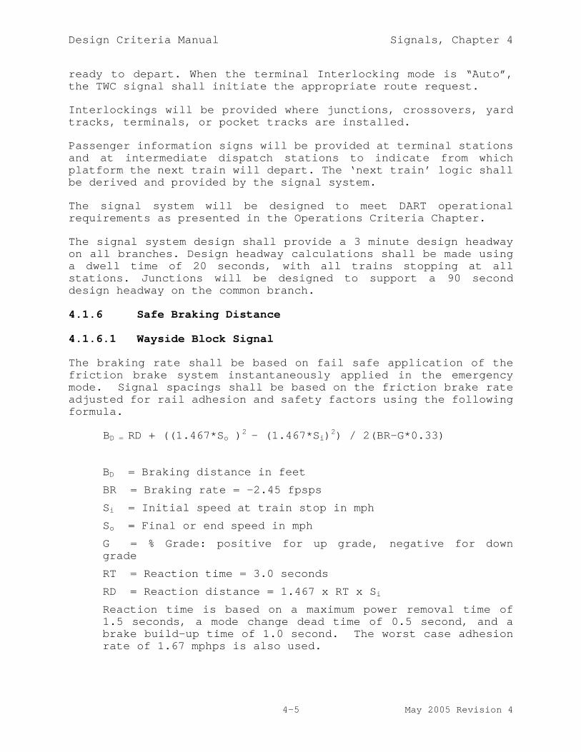
Design Criteria Manual Signals, Chapter 4
4-5 May 2005 Revision 4
ready to depart. When the terminal Interlocking mode is “Auto”,the TWC signal shall initiate the appropriate route request.
Interlockings will be provided where junctions, crossovers, yardtracks, terminals, or pocket tracks are installed.
Passenger information signs will be provided at terminal stationsand at intermediate dispatch stations to indicate from whichplatform the next train will depart. The ‘next train’ logic shallbe derived and provided by the signal system.
The signal system will be designed to meet DART operationalrequirements as presented in the Operations Criteria Chapter.
The signal system design shall provide a 3 minute design headwayon all branches. Design headway calculations shall be made usinga dwell time of 20 seconds, with all trains stopping at allstations. Junctions will be designed to support a 90 seconddesign headway on the common branch.
4.1.6 Safe Braking Distance
4.1.6.1 Wayside Block Signal
The braking rate shall be based on fail safe application of thefriction brake system instantaneously applied in the emergencymode. Signal spacings shall be based on the friction brake rateadjusted for rail adhesion and safety factors using the followingformula.
BD = RD + ((1.467*So )2 - (1.467*Si)2) / 2(BR-G*0.33)
BD = Braking distance in feet
BR = Braking rate = -2.45 fpsps
Si = Initial speed at train stop in mph
So = Final or end speed in mph
G = % Grade: positive for up grade, negative for downgrade
RT = Reaction time = 3.0 seconds
RD = Reaction distance = 1.467 x RT x Si
Reaction time is based on a maximum power removal time of1.5 seconds, a mode change dead time of 0.5 second, and abrake build-up time of 1.0 second. The worst case adhesionrate of 1.67 mphps is also used.

Design Criteria Manual Signals, Chapter 4
4-6 May 2005 Revision 4
4.1.6.2 Cab Signal
Safe Braking Distance for determination of proper speed codesshall be based on a braking model that simulates the worst casebraking effort. The model shall simulate braking as a series ofconsecutive events, defined as follows:
a) Primary Reaction Distance – The distance traveled by avehicle at the initial velocity as it crosses a blockboundary. The distance is that traveled through the“dead” section where a valid code may be unavailable.The initial velocity to be used is the previous speedcode plus the overspeed tolerance of the vehicle cabsignal equipment. In the model, acceleration due todownhill slope should be considered.
b) Code Recognition Time – The worst-case period that thevehicle equipment would take to recognize a valid speedcode. Assume the vehicle is speed-maintaining throughthis period. Include acceleration due to downhillslope.
c) Runaway Acceleration – Assumes a propulsion systemcontrol failure that sends the vehicle into fullacceleration at the maximum available rate adjusted forgrade. The runaway acceleration occurs until the systemhas detected an overspeed condition and initiated powerremoval.
d) Mode Change Time – The time for the vehicle equipmentto remove power and initiate a brake command after anoverspeed has been detected. During this period, poweris removed and acceleration force of grade is included.
e) Brake Build-up Time – The time from the initiation ofbraking until full deceleration is achieved. Duringthis period, braking shall be calculated as a linearincrease from 0 to full braking.
f) Constant Braking – When the brakes have built up tomaximum deceleration, the braking model shall completethe braking at a constant brake rate adjusted forgrade. Twice the vehicle overhang distance is added tothis value.
4.1.7 Equipment Requirements
Modular design shall be used throughout the systems. Electricaland mechanical components shall be organized in plug-inassemblies wherever practical and be rack mounted.

Design Criteria Manual Signals, Chapter 4
4-7 May 2005 Revision 4
4.1.7.1 Rack Mounting
All equipment and components mounted on racks shall be accessiblefor testing or replacement without removal of other components.
Design shall provide for cooling air space around alltransformers, rectifiers, reactors, and other heat generatingdevices.
All relays, equipment, and entrance racks will have referencetest points for all voltages associated with the equipmentinstalled on such racks.
4.1.7.2 Environment
Physical:
All equipment housed in CIH's and cases will be designed tofunction without damage within a temperature range of –40ºC to+71ºC (-40ºF to +160ºF) and relative humidity of 0 percent to 95percent, noncondensing.
Any equipment housing that will hold microprocessor equipmentshall have forced ventilation and air conditioning. Both fan andair conditioning shall be thermostatically controlled. Thecontrol shall be interlocked so that at a selected temperature,the fan is switched off and the air conditioner is switched on.
Vibration:
Signal equipment shall be designed to operate safely and reliablywhile exposed to vibrations of 2-10 Hz, 0.2 inch displacement,peak to peak; and at 10-500 Hz. at 1.0G.
4.2 VITAL FUNCTIONS
A vital function is any circuit or software logic that can affectsafety of train operations. All vital functions shall meet thefail safe design principles described herein.
Fail Safe Design Criteria - Vital logic design shall be based onclosed loop circuit principals with the operator considered as anactive element.
Component or system failures that are not self-detecting shallnot cause unsafe conditions, even if added to other failures. Anynumber of simultaneous component or system failures attributableto the same cause or related causes shall not cause unsafeconditions.

Design Criteria Manual Signals, Chapter 4
4-8 May 2005 Revision 4
Any component becoming grounded, or any combination of suchgrounds shall not cause unsafe conditions.
4.2.1 Vital Relay Systems
Vital relay circuits shall meet AREMA Signal Manualrequirements.
Except when specified, all circuits which leave a housing shallbe double break, using ungrounded DC power supplies. Side-by-side above ground housings interconnected by vandal proof,weather tight enclosures shall be considered one housing. Thecable way between adjacent housings shall be limited to a 50percent fill limit.
Vital functions contained within a CIH or case shall be positiveenergy, single break equations or circuits.
All vital repeater relay circuits shall be designed on thecascade principle. Paralleling of vital repeater relays shallnot be permitted.
Repeater relay contacts shall be so assigned that safety willnot be compromised by failure of any repeater relay to energize.
Non-vital contacts used in vital circuits shall only bepermitted in the energy feed of a circuit. If non-vital contactsare used in vital circuits it shall be assumed these relays canfail and an armature may stick in any position. None of theabove events shall cause an unsafe condition.
4.2.2 Vital Microprocessor Systems
Where used for interlockings, redundant vital processor systemsshall be installed in a warm standby configuration with anautomatic switch-over when a failure is detected.
4.2.3 Locking Functions
Locking functions shall prevent unsafe switch operation andprevent clearing of signals for opposing or conflicting routes.Types of locking to be provided are as follows:
4.2.3.1 Approach Locking
Approach locking shall lock switches within a route governed by acleared wayside signal when a train is occupying the approachcircuit to such signal. Once initiated, approach locking willremain in effect until the locking time has transpired or untilreleased by the occupancy of the first two track circuits in thelocked route. Approach locking shall prevent clearing of wayside

Design Criteria Manual Signals, Chapter 4
4-9 May 2005 Revision 4
signals for opposing or conflicting routes for a predeterminedtime after a cleared wayside signal has been reset to stop unlessthe approach to such signal was unoccupied while the signal wascleared. Approach locking shall be provided for all controlledsignals. Approach release time shall be calculated in accordancewith AREMA Signal Manual Section 2.4.20.
4.2.3.2 Time Locking
Time locking shall be provided for electric locked hand-operatedswitches within a route governed by a cleared wayside signal.Opposing or conflicting routes shall be locked until released byTrain Control Center (TCC) or the local control panel.
4.2.3.3 Route Locking
Route locking shall lock all switches within a route when asignal is cleared and shall maintain the locking after a trainhas accepted the wayside signal governing such route andcompleted its travel through the route. Portions of the routebehind the train shall be released when it is safe to do so.Route locking shall also lock switches outside the route when setby the route-selection system to provide overrun foulingprotection.
4.2.3.4 Sectional Release
Where necessary to meet headway requirements, switch lockingcircuits shall be designed with sectional release. Such designis required to release each switch after the final axle of avehicle has vacated the detector locking track circuit, providingthat the train no longer fouls the vacated portion of the route.
4.2.3.5 Detector Locking
Detector locking shall lock all switches within the limits of atrack circuit when such track circuit is occupied. Detectorlocking shall not be released by momentary loss of shunt.
4.2.3.6 Switch Locking
Switches at interlockings shall be locked by approach locking,time locking, route locking, and detector locking. Switchlocking shall be released when approach locking, time locking,route locking, and detector locking are released.
4.2.3.7 Time Release Locking
Time Release Locking is to provide safe entry into an occupiedturnback track, storage track, or terminal track. The vital

Design Criteria Manual Signals, Chapter 4
4-10 May 2005 Revision 4
timer shall be adjustable from 5 to 60 seconds. Time releaseshall operate upon detection of train occupancy in a turnbacktrack, storage track or terminal track, and thus allow a call-onsignal to be requested after completion of time. The length oftime adjustment shall ensure the train occupying the interlockingcan stop before a call-on route is allowed.
All vital timing functions required to energize a circuit shalluse vital timers with adjustable time settings. Mechanicaltimers shall provide back check logic. Such back check logic ina vital circuitry will assure that time has fully run beforereset. Time settings shall be shown on route and locking chartsand on circuit drawings next to timer symbols. Each signal shallhave a dedicated timer.
4.2.3.8 Traffic Locking
Traffic locking shall prevent clearing opposing signals into asection of track. Individual traffic circuits shall be providedfor each section of track between interlockings.
Direction of traffic shall be locked on a section of track overwhich traffic locking is provided when any track circuit withinthat track section is occupied, when traffic direction isrequested into that track section, or when approach or timelocking is effective for a signal which had been cleared intosuch track section. Traffic direction, once established willremain locked until unlocked and a request is made to enter fromthe opposite end. Traffic direction shall be locked while thetraffic section is occupied, including the exiting interlockingtrack circuits except where the route is freed by sectionalrelease.
A signal governing movement into a section of track for whichTraffic Locking is effective shall not clear until trafficdirection has been established and locked in the direction ofmovement and the individual traffic relays in each ABS case arepicked in proper alignment for the direction of traffic.
Clearing of ABS signals will be controlled by the direction oftraffic. ABS signals will not clear until traffic relays for theproper direction are energized.
Traffic logic shall initiate a change of direction by a routerequest from the local train storage system without the aid ofthe remote train storage subsystem or presence of a person at theadjacent signal CIH.

Design Criteria Manual Signals, Chapter 4
4-11 May 2005 Revision 4
4.2.4 Signal Clearing
Route check circuits shall be provided to prevent prematurelocking. The route check shall initiate signal clearing for eachsignal which governs movement over a track containing a trackswitch. A route check relay shall be energized to initiatewayside signal clearing only when switch point positionscorrespond to the positions required for the route between theselected entrance and exit points, an opposing signal has notbeen called, and an opposing movement is not in progress.
Signal clearing shall be effective for the route selected whenthe proper route check relay is energized, and approach, time,and traffic locking for an opposing or conflicting route is notin effect.
For signals that do not govern movements over track switches,signal clearing shall be initiated directly from the entrancepoint if an opposing signal has not been called and no opposingtrain movement is in progress.
Signal indication circuits shall indicate and distinguish betweena signal being called, the same signal being clear, and suchsignal being in time locking.
4.2.5 Signal Lighting
A signal indicating route alignment shall display aspects aspreviously described. Each signal aspect shall be energizedthrough vital contacts or driver circuits. Such aspects shall beenergized when the route is aligned regardless of presence orabsence of a train in approach to the signal. Occupancy of theapproach shall energize the signal regardless of trafficdirection. Signal lighting circuitry shall prevent undesirableflashes of inappropriate aspects when changing from one aspect toanother.
4.2.6 Fleeting Circuit Requirements
Fleeting circuits shall automatically reestablish energy to thesignal clearing circuit, after train passage, whenever a fleetcontrol button for a signal has been placed in fleeting position.Fleeting shall be provided for normal and reverse direction oftraffic.
When a signal has been fleeted, it shall not re-clear untilcircuit requirements are met as defined by the control lines.
Canceling a fleet request shall not cancel the route.

Design Criteria Manual Signals, Chapter 4
4-12 May 2005 Revision 4
4.2.7 Signal Blocking
Signal Blocking Circuits shall be provided for each interlockingsignal. Blocking circuits will be initiated from TCC or thelocal control panel. Signal blocking will prevent an exit at thesignal selected. Signal block circuits shall be interfaced withthe vital home relay circuits to prevent an exit at the signalselected and interfaced with non-vital logic circuits to preventa preliminary exit indication at the signal selected.
4.2.8 Line Circuits
Line circuits shall be provided to pass information betweenlocations. Line circuits may be dedicated, traffic reversed, DCcoded, or vital serial communications, as necessary to providecomplete logic information to control trains.
4.2.9 Approach Circuits
An approach circuit shall be provided for each interlockingsignal. The approach section shall include all track circuits inapproach of the interlocking signal within braking distance ofsuch signal. Where signals are approach cleared, additionalapproach circuits used to make a signal request shall includetrack circuits in approach to the approach signal sufficient toensure that the home signal can clear (including worst caseswitch throw time) and that the approach signal is cleared toallow at least three seconds of viewing time for a traintraveling at the maximum allowable speed.
4.2.10 Lightning Protection
Lightning protection shall be provided in the design of theSignal System in accordance with AREMA Signal Manual Part 11.2.1.In addition, the design shall provide for lightning protectionand surge protection on all track circuits and electronics.Inputs to electronic components from devices external to the caseor instrument house where the electronic equipment is locatedshall be protected.
4.2.11 Track Circuits
4.2.11.1 ABS Areas and Crossovers
Track detection shall be accomplished by two-element vane relaytype track circuits, utilizing 100 Hz steady energy. Shuntingsensitivity shall be 0.25 ohm under dry weather conditions. Trackcircuits shall be capable of properly functioning in a directcurrent traction power system environment, utilizing vehicleswith AC traction motors.

Design Criteria Manual Signals, Chapter 4
4-13 May 2005 Revision 4
Track circuit shall provide broken rail protection for both railson normal routes and single rail circuits on the crossoverportion of turnouts.
Track circuit equipment shall either detect the failure of anyinsulated joint or protect against it causing an unsafecondition.
Track circuits shall operate correctly with ballast resistance aslow as 5 ohms per thousand feet.
Five second loss of shunt protection shall be included withininterlockings to prevent switch movement within such time period.
Design of the track circuit system shall take into considerationcross bonding for traction power negative returns as required.
4.2.11.2 Cab Signal
Main line track circuits in cab signaled territory shall bejointless audio frequency type.
Track circuits in crossovers shall be power frequency. Loopsthrough turnouts shall be used to transmit speed codes.
4.2.12 Switch Operating Circuits
Switch operating circuits shall enable power switch machines tooperate if locking is not in effect. Switch operating circuitsshall be two-wire. Each switch machine motor shall be energizedby an individual ungrounded power supply. Power shall be removedwhen the switch has reached the requested position and is incorrespondence.
4.2.12.1 Switch Overload
Switch overload circuits shall protect each switch-and-lockmovement by using a switch overload stick circuit. An overloadstick circuit shall be provided for each switch machine motor.Overload circuits shall remove energy from a switch machine whenthe operating current rises above the desired maximum due tostalled points or other causes of overload. Once the overloadhas occurred, energy shall remain off until the switch is calledto the opposite direction. Time for pickup of the overload relayshall be the manufacturer's recommendation, but shall not exceedten (10) seconds.
4.2.12.2 Switch Repeater
Switch repeater circuits for switch-and-lock movements shallindicate the normal or reverse position of switch points. One

Design Criteria Manual Signals, Chapter 4
4-14 May 2005 Revision 4
normal and one reverse switch repeater relay shall be providedfor each crossover or turnout. When the switch repeater relay iscontrolled by two or more switches that make up a crossover, allswitches must be mechanically and electrically locked in a normalor reverse position before switch repeater circuits can beenergized.
4.2.12.3 Switch Correspondence
Switch correspondence circuits shall have relays separate fromswitch repeater relays and check that position of the switch inthe field is in agreement with the position requested at TCC orfrom the local panel. Switch correspondence circuits shallindicate correspondence between switch position and switchrequest. One normal and one reverse switch correspondence relaywill be provided for each crossover. A switch correspondencerelay shall be energized when position of switch points asindicated by the switch repeater circuit agrees with the switchrequest as produced by switch control circuits.
4.2.12.4 Switch Blocking
A switch blocking circuit shall be provided for each switchwithin an interlocking. The block will be initiated from TCC orthe local control panel. This block shall be vitally interfacedwith switch and signal circuits to prevent operation of suchswitch when the block is in effect.
4.2.13 Control Functions
The following conditions are necessary to clear a route:
a) All switches are aligned and locked in the properposition.
b) Traffic is properly aligned and locked in the directionof travel for the track section being entered.
c) Tracks are unoccupied within the interlocking routebeing cleared and an overrun condition does not exist.
d) An unsafe or conflicting condition does not exist. Allspecial conditions required by the interlocking aresatisfied.
When a cleared route is canceled, interlocking logic shall ensuretime locking and traffic locking remain in effect for acalculated time. Time shall be calculated based on sufficienttime to achieve braking to a full stop and not overrun thesignal. Logic shall not run time when the approach block to the

Design Criteria Manual Signals, Chapter 4
4-15 May 2005 Revision 4
specific signal is, and has been unoccupied while the signal wasclear.
When a route is canceled there shall be no attempt to provideautomatic routing for the next train which occupies the approachor advance approach at the time of canceling.
In ABS territory, the signal system shall allow trains to proceedat rule book speed up to an interlocking signal at stop. Amagnetic train stop shall protect overrun by causing an emergencybrake application.
At turnback tracks, storage tracks, terminals or other specialcircumstances, automatic routes shall not be cleared when thedestination track is occupied. TCC, local control panel orwayside push button will request a call-on or restricting route.A call-on will be displayed after a predetermined time to ensurean approaching train has stopped.
Train destination routing shall be used at locations where two ormore destinations are possible. Train destination shall bedecoded from TWC prior to the advance approach track. Routerequests shall be initiated at the signal in advance of thedistant signal, if conditions permit. If the route cannot becleared, the destination shall be stored and the route initiatedwhen conditions permit. The system shall use a storage registerto store requested routes for all following trains entering anautomatic routing zone. The storage register shall advance whenthe train enters the interlocking. When storage registeridentities are out of sequence with actual conditions it shall becorrected by a storage register identity clear out circuit
Train ready routing shall be initiated from a train readyindication sent by the TWC subsystem. Operation of the trainready button on a vehicle shall request routes at terminals.
Auxiliary Switch Control circuit shall be initiated by a signalfrom the TWC to move power operated switches either normal orreverse for designated automatic routes.
At converging junctions or other locations as required, TCC shallhave the capability of inhibiting any automatic route from beinginitiated while in automatic operation.
If the data link to TCC is not functioning, the inhibit shall beremoved and the signal will operate automatically. Automaticsignal inhibit must be initiated for each train.

Design Criteria Manual Signals, Chapter 4
4-16 May 2005 Revision 4
4.3 NON-VITAL FUNCTIONS
Non-vital circuits may use vital or non-vital equipment aspredicated by design requirements.
Non-vital circuits which leave a CIH or case may be single break.
Logic to perform the following functions shall be provided.These functions shall include, but not be limited to:
4.3.1 Route Clearing
Route clearing shall be entrance/exit logic from local, automaticand Train Control Center.
4.4 SYSTEM CONTROL
In the TCC, an overview display will show status of the entireSystem. Individual terminals will permit detailed monitoring ofsmaller sections of the system or individual interlockings.Subsystem failures that could affect the safety or reliability ofthe System will be shown as alarms. Functions available todispatchers shall include the ability to control interlockingsfor special moves or hold trains at stations.
Controls and indications shall be communicated between waysidesignal equipment and the TCC via the SCADA system. The signalsystem shall provide RTU functions to collect requiredinformation and communicate it in the necessary format andprotocol.
4.4.1 Control Mode Hierarchy
Local control panels shall be provided with two key-operatedswitches that permit an override of TCC control. The mode-selector switch shall allow switching from Automatic or Localcontrol to TCC control. To switch out of the TCC mode, a signalreleasing control must be received from the TCC. An emergencykey-operated switch shall allow an override and permit control tobe switched without TCC concurrence.
4.4.2 Automatic Routing
Circuitry to automatically align routes shall be as follows:
4.4.2.1 Automatic Clearing - Route
All normal direction routes shall be automatically cleared.

Design Criteria Manual Signals, Chapter 4
4-17 May 2005 Revision 4
4.4.2.2 Automatic Clearing - Train Destination
Detection of a train on the advance approach shall cause theinitiation logic to clear a route depending on train destination.
If the route is not available while the train is on the advanceapproach and has subsequently moved into the approach circuit,the logic shall wait until the route is available and then clearthe signal.
When an automatically cleared route is canceled, it shall notreclear automatically until the advance approach and approachbecome unoccupied by the train that requested the signal toautomatically clear.
4.4.2.3 Automatic Clearing - Approach Only
Interlocking signals with one possible automatic route shall becleared by train detection only. When more than one train iswithin the advance approach, the signal will clear for eachsucceeding train as conditions ahead permit.
4.4.2.4 Automatic Clearing - Train Ready
Operations at turnbacks and terminals may require specialautomatic clearing methods. Detection of train ready from theTWC system shall be provided as necessary to clear automaticroutes.
4.4.2.5 Destination Decoding, Storage and Transmission
ID and destination received from the train via TWC shall permitthe clearing of interlocking signals.
4.4.2.6 Unidentified Train
An unidentified train ID or destination shall be entered in theproper message sequence with other normal trains. Theunidentified data may be generated by the decoder when anincorrect TWC message is received or by track occupancy when noTWC message is received.
4.4.2.7 Automatic Register Clear
A register clear shall be generated when a code is stored and atrain is not on the advance approach or approach (code without atrain) or when there is a train on the advance approach orapproach and there is no code in the register (train without acode).

Design Criteria Manual Signals, Chapter 4
4-18 May 2005 Revision 4
4.4.2.8 Route Rotating Priority
Automatic route rotating priority shall be provided to controlthe flow of trains through interlockings where conflictingautomatic and/or wayside push button requests will be vying forroutes through interlockings.
4.4.3 Terminal Control
Train operation at terminal interlockings shall be sequenced bymode selection. Dual mode control logic that can be controlledby the local control panel or TCC shall be provided. Modeselection logic shall automatically determine the tail trackand/or platform track that each train will take as it arrives atthe terminal. Operation shall be as follows:
a) Mode 1 will be set for trains approaching terminallocations to diverge to the left side track stationplatform and depart from there on a straight route.
b) Mode 2 will be set for trains to alternate platformswhen more than one train is to be at the station at onetime.
c) Mode 3 will be set for trains to approach terminallocations on the right side track and cross over upondeparture.
If both tracks are available, the train will be routed to thenormal inbound departure track.
4.4.4 Local Control Panel
The local control panel shall utilize push button operation tocontrol entrance/exit logic operation at all locations. Thelocal control panel shall have a key operated control mode.
Control push buttons and indicators shall be provided to enterroute requests, operate switches, enable automatic routes,control terminal mode and indicate status of power, fuses,grounds, and other miscellaneous information.
4.4.4.1 Switch Position Indication
A Switch Position Indication push button shall be provided. Whenpushed and held in, it shall cause all current switch positionsto illuminate. It shall be possible to operate this buttonwithout use of the key switch to observe switch positions.

Design Criteria Manual Signals, Chapter 4
4-19 May 2005 Revision 4
4.4.4.2 Entrance/Exit Operation Control
Interlockings shall be provided with entrance/exit operation forroute selection/signal clearing. A push button shall be locatedon the track diagram at each possible entrance or exit point.Pushing an entrance/exit push button shall establish an entrancerequest, which will cause the appropriate entrance indicator toilluminate steady white, and cause the indicators at push buttonsfor all available exits to illuminate flashing white. Pressingone (1) of the available exit push buttons shall establish aroute between selected entry and exit points, and shall cause allother flashing exit indicators to go dark.
Routes shall be canceled by pulling the signal indicator pushbutton for the entry point of the specific route.
4.4.4.3 Terminal Mode Selection
Terminal mode selection shall be by means of a rotary selectorswitch located on a separate panel. The panel may be locatedwithin the CIH, adjacent to the local control panel, or in aweatherproof box in the station area. Terminal mode functionsshall be made available in the TCC via the SCADA system. Theselected mode as described in Section 4.4.3 will be indicated byyellow lamps.
4.4.4.4 Panel Indications
Indicators provided shall include (but not be limited to) thefollowing functions:
a) TCC/Local Indicator.
b) Signal Indicators.
c) Switch Position Indicators.
d) Switch Locked Indicators.
e) Traffic Direction Indicators.
f) Interlocking Track Occupancy Indicators.
g) Non-Interlocking Track Occupancy Indicators.
The following alarm indicators are to be illuminated when theassociated alarm condition exists, regardless of TCC/Local switchand Panel Lights switch position. These alarms shall be sent toTCC and also be used to control the CIH alarm light inconjunction with the high temperature alarm:
a) Blown Fuse Indicators.

Design Criteria Manual Signals, Chapter 4
4-20 May 2005 Revision 4
b) Power Off Indicators.
c) AC Line Indicators.
d) Data Transmission System Failure Indicator.
e) Ground Detector Indicator.
f) Wayside Case Failure Indicators.
g) Intrusion Indicators.
4.4.4.5 Switch Preconditioning
Switch preconditioning is prohibited.
4.5 NON-VITAL ELECTRONIC CIRCUITS
Non-vital electronic circuitry shall be used in conjunction withrelay logic circuitry where applicable. Diode based circuits maybe used where applicable to provide isolation of energy in non-vital circuits.
TWC circuits and associated equipment for automatic ID routing(destination decoding and shift register) shall be microprocessorbased.
4.6 ENERGY DISTRIBUTION CIRCUITS
Source energy for the signal power distribution system shall beobtained from Traction Power Substation auxiliary panelboardbreakers. Where required and DART approved, the design may use aTXU power source in lieu of the signal power distribution centersource.
Distribution circuits shall distribute AC and DC energy to theracks and equipment with voltage drops of less than five (5)percent maximum. Such drop shall not affect the properperformance of equipment. These tolerances shall be measuredbetween power source and load.
4.6.1 AC Power Distribution
AC power shall be distributed as required to all signallocations. Signal power distribution centers shall be provided asnear to the Traction Power Substation as possible. Powerdistribution centers shall consist of two-480 VAC two pole,thermal magnetic, molded case circuit breakers housed in NEMA 12enclosures.
Step-down transformers shall be provided at each location asrequired by the design.

Design Criteria Manual Signals, Chapter 4
4-21 May 2005 Revision 4
The design shall provide protective devices for each functionsuch that failure in one (1) circuit will not affect more thanone (1) function. Function to be individually protected shallinclude but not be limited to the following:
a) Each power supply,
b) Each wayside signal,
c) Each traffic rectifier,
d) Each switch machine rectifier,
e) AC ground detector,
f) Each AC track circuit,
g) RTU Power Supply,
h) Interface circuits to TCC.
4.6.1.1 ABS Territory
Distribution voltage shall be 480 volts 100 Hz for track circuitsand 480 volts 60 Hz for signal power. The source for trackcircuit power shall be from a solid state frequency converterlocated at signal power distribution centers. Signal powerdistribution shall consist of one 480 VAC single-phase two wire100 Hz track circuit power and 480 VAC single-phase two wire 60Hz express power cables installed in an underground duct system,cable trough or trench along the right-of-way. Sectionalizingshall be provided in the transmission line by means of doublepole, single throw switches at various locations.
4.6.1.2 Cab Signal Territory
480 Volt, 60 Hz power shall be obtained at the SPDC anddistributed to signal equipment locations.
At interlockings, inverters shall convert DC battery source to100 Hz. supply for power frequency track circuits.
At junctions and terminal interlockings, an alternate source forback-up AC power shall be obtained. An automatic transfer switchshall detect when the primary source value drops below a setlimit and transfer to the alternate source. The transfer switchshall automatically restore the system to the primary source whenthe voltage of the primary source rises to a set value after adelay to ensure stability.
Where an alternate source is provided, the load shall besegregated onto “Essential” and “Nonessential” busses. The

Design Criteria Manual Signals, Chapter 4
4-22 May 2005 Revision 4
Essential buss shall receive power from the automatic transferswitch and the Nonessential buss shall receive power from theprimary source only.
4.6.2 DC Power Distribution
DC power shall be produced at each signal equipment controllocation using transformers and rectifiers appropriate for theapplication. Backup batteries shall be sealed type with nooutgassing or requirements for adding water. Batteries andchargers shall be provided at all CIH's for all vital and non-vital circuits and/or processors.
Positive and negative DC energy shall be distributed on logicracks in the form of energy loops. Wire size of the energy loopshall be capable of carrying full loop current.
A voltage reference wire for each power buss shall be designed toserve racks, wayside equipment, junction boxes, switch machines,and other required components. This reference wire shall providea means for voltage readings when only one side of the power bussis used in any particular location.
4.6.2.1 ABS Territory
Batteries shall be designed to support operations by preventingsignal system stick circuits or similar software logic fromcanceling after a power failure is restored. Batteries shall besized to hold stick circuits or processor memory for 8 hoursafter power failure. The circuits shall be designed such thatenergy from one fuse does not connect to energy from anotherfuse.
The design shall provide protective devices for each functionsuch that failures in one circuit will not affect more than onefunction except on logic racks. Functions to be protectedindividually shall include but not be limited to the following:
a) Each track circuit,
b) Local Control Panel Lighting,
c) Local Control Panel Controls,
d) Each TWC Unit, route decoder, and storage register.
4.6.2.2 Cab Signal Territory
All equipment necessary to operate normal routes using cabsignals and to maintain data communications shall have at least

Design Criteria Manual Signals, Chapter 4
4-23 May 2005 Revision 4
eight hours of battery backup, calculated to include rush hourservice levels.
4.6.3 Ground Detection
Ground detection shall be provided on the 110 volt AC used forsignal lighting and other signal functions and for ungrounded DCvoltage used for line and logic circuits.
4.7 WAYSIDE SIGNAL EQUIPMENT
This section defines the design requirement of wayside signalcomponents including:
a) Switch-and-Lock Movements
b) Impedance Bonds
c) Rail Connections
d) Insulated Joints
e) Conduits and Accessories
f) Cables
g) Overlay Track Circuits
h) Loop Vehicle Detectors
i) Wayside Signals
j) Wayside Train Stops
k) Housings
l) Train-to-Wayside Communications
m) Junction Boxes
n) Carborne Equipment
4.7.1 General
All wayside signal system equipment shall be designed,constructed, and installed to operate in an environmentencountered in the Dallas area. The following particularconditions shall be used as design guidelines and shall beconsidered as operational requirements. Actual localizedtemperatures and conditions within spaces and enclosures may bemore severe than the ambient climatic conditions and shall beevaluated during the design effort to ensure that no damageoccurs during manufacture, storage, and shipment as a result ofclimatic conditions that differ from those below:

Design Criteria Manual Signals, Chapter 4
4-24 May 2005 Revision 4
Temperature & Solar Load:
Minimum ambient air temperature external to equipment: 4°F
Maximum ambient air temperature external to equipment:115°FMaximum solar radiation: 275/BTU/hrft²
Maximum daily temperature range: 50°F
Average days less than 32°F 38
Precipitation:
Maximum rainfall rate (may occur simultaneously in a worstcase wind): 7"/hr.
Maximum snowfall: Measurable quantities (infrequently)
Ice: Measurable quantities (infrequently)
Average Relative Humidity:
Morning: 82%
Afternoon: 56%
Max Average: 87%
Wind:
Average speed: 11 mph
Maximum sustained for 1 minute: 70 mph
Maximum gusting: 70 mph
Air Contamination. Equipment shall operate as specified inthe atmosphere commonly found in rail vehicle environmentsand the Dallas Metropolitan region. These include thefollowing:
Particulates:
Average: 0.175 mg/m³
Maximum 0.324 mg/m³
Ozone: 0.200 ppm, max.
NO2: 0.25 ppm, max.
SO2: 262 µg/m³
CO: 20 ppm, max.
Chloride: 13.9 mg/m³
Moisture Acidity pH 4.41

Design Criteria Manual Signals, Chapter 4
4-25 May 2005 Revision 4
4.7.1.1 Clearance
Wayside signal equipment shall be located outside the Light RailVehicle dynamic clearance envelope.
4.7.1.2 Installation
Wayside signal equipment shall be installed in a manner to bedirectly accessible for maintenance and to allow for efficientremoval and/or replacement. Signal equipment shall be installedso as to cause a minimum of interference with periodic trackmaintenance.
4.7.1.3 Wayside Signal Equipment Grounding
A grounding system shall be provided for wayside signal systemequipment in accordance with AREMA Signal Manual Section 11.4.It will be the installation contractor's responsibility todevelop a grounding system for wayside signal equipment forconnection to a ground network provided by others, whereapplicable. DC resistance to ground shall not exceed 5 ohms.
4.7.2 Main Line Switch-and-Lock Movements
Remote controlled main line switch-and-lock layouts shall includea dual control 120 VDC switch-and-lock movement with a maximumswitch throw distance of 4 3/4 inches. Switch-and-lock movementsshall be mechanically coupled to the track switch points andsecurely mounted to ties in ballasted track areas or secured toconcrete in direct fixation areas. Switch-and-lock movementsshall be insulated from the track and be at ground potential onlywhere the mechanical connection to the tie is in contact withearth.
The signal system contractor shall interface to track switchequipment. The track contractor will supply one operating basketfor each switch. The signal system contractor shall supply thebasket nuts (cone and lock). Track contractor will supply anddap the headblock ties, and extra length ties, as required.
4.7.3 Impedance Bonds
4.7.3.1 General
Impedance bonds shall be provided at all locations requiringsignal system and traction power return interconnection with therunning rails. Track windings of the impedance bond shall becapable of carrying maximum current requirements of the TractionElectrification System. Impedance bonds shall function properlywith a traction current imbalance within ten (10) percent.

Design Criteria Manual Signals, Chapter 4
4-26 May 2005 Revision 4
Impedance bonds shall be capable of sustaining a surge of 10,000amps per rail for one (1) second.
Where provided in cab signal territory, impedance bonds shallinclude tuning units for track circuit transmitter and receiverfrequencies, as well as the cab signal frequency.
4.7.3.2 Installation
In tie and ballast areas, impedance bonds shall be mounted toprovide a minimum of one (1) inch clearance below top of railusing lag screws to fasten the layout to the ties. If signalsystem contractor's impedance bond layout requires a separatefield tuning unit both bond and tuning unit shall be mountedtogether on a steel plate and fastened to the ties. When mountedon concrete ties, stainless steel fasteners shall be used tosecure the steel plate.
On direct fixation locations, impedance bond layouts shall bemounted to provide a minimum of one (1) inch clearance below topof rail. There shall be a one-half (1/2) inch minimum spaceunder the impedance bond. If a separate tuning unit is required,tuning units and bond shall be mounted on a steel plate and theplate affixed to the concrete with one-half (1/2) inch spaceunder the plate.
4.7.4 Rail Connections
4.7.4.1 General
The signal system contractor shall provide and test allconnections, cable, and connection accessories required on therunning rails. Cable size No. 6 AWG and larger shall beconnected to rails via exothermic welding.
4.7.4.2 Impedance Bonds
Traction power track leads shall be connected to the center ofthe rail web by exothermic welding. Crossbonding shall beprovided at locations to be determined by block design andtraction power requirements. Crossbonding cable shall beconnected to the impedance bond center tap. Substation negativereturn cables shall be installed from impedance bonds to riserterminal cable adapters in accordance with traction powerrequirements. Substation negative return cables shall beconnected to the bond center tap.

Design Criteria Manual Signals, Chapter 4
4-27 May 2005 Revision 4
4.7.4.3 Mechanical Joint Power Bonding
Rail head bonds shall be provided for mechanical joints (minimumof two (2) 250 KCMIL), frog jumpers (minimum of a single 500KCMIL), switch point jumpers (minimum of a single 500 KCMIL), andfouling jumpers (minimum of two (2) 500 KCMIL) as required. Sizeof the jumpers shall be coordinated with the TractionElectrification System and provide maximum broken railprotection. Traction power jumpers shall be connected to therail by exothermic welding.
4.7.5 Insulated Joints
Insulated joints shall be furnished and installed by the trackcontractor at locations determined by signal system design.Staggered distance of a pair of insulated joints shall not exceed4-1/2 feet and the preferred distance will be 2-1/2 feet.
4.7.6 Conduit and Accessories
Typically, all conduits under track will be provided by the civilcontractor. The signal system contractor shall provide allconduits and accessories above ground required for the waysidesignal system equipment. Conduit used above ground shall begalvanized rigid steel. All open unused entrances in the cabletray shall be closed by the contractor. All ballast or roadsurface removed or altered during conduit installation shall berestored to original condition by contractor. Location ofconduits shall be indicated on the cable plans. Contractor shallleave thirty (30) percent spare space in conduits.
4.7.7 Cables
Cable used for vital signal circuits shall be specified inaccordance with standard signal industry practice for vitalsignal safety circuits. Cables specified shall have a provenhistory of use on transit and railroad vital signal systems.
4.7.8 Overlay Track Circuits
Where required for short range train detection within a largerdetection zone, overlay track circuits shall be used. Overlaytrack circuits shall operate in the audio frequency range.Frequency of overlay track circuits shall not create interferencewith any other system or subsystem on the wayside or onboard thevehicle. Pre-shunt and post-shunt of overlay track circuits shallbe less than thirty feet.

Design Criteria Manual Signals, Chapter 4
4-28 May 2005 Revision 4
4.7.9 Loop Vehicle Detectors
Where track circuits are not practicable, vital train detectionshall be accomplished using loop vehicle detectors.
4.7.10 Wayside Signals
Interlocking and automatic signal layouts shall include signalheads, brackets, electrical fittings, junction boxes, terminals,and hardware required for installation. Masts and foundationsshall also be provided.
Signal heads shall be three aspect color light type. The toplens of each signal head shall be green, middle lens yellow, andbottom lens red. Route indicators shall be masked with an arrowcorresponding to the route.
Ladders shall be complete with stays, fasteners, extensions, andother necessary hardware. Ladders shall be as appropriate toeach particular location. Ladders shall be provided where thehighest aspect is mounted more than six (6) FT above the surfacewhere a maintainer can stand.
Wayside signal layouts mounted in ballasted areas shall beinstalled on concrete foundations either of monolithic orsectional construction.
Wayside signals mounted in direct fixation track areas shall bemounted to the concrete structure or wall as appropriate. Allfastening to concrete shall be with pre-packaged epoxy adhesive.Fasteners shall be stainless steel hardware. Concrete drillingshall be done using approved steel template.
4.7.11 Train Stops
Wayside magnetic train stop layouts shall be installed at allwayside signal locations to activate the carborne magnet tocommand an emergency brake application. Train stop layouts shallinclude a wayside magnet, brackets, electrical fittings, junctionboxes, terminals and hardware for installation. Wayside magnetsshall be mounted between the rails. Train stop layouts shall bedesigned to be fail safe in that a failure of any component willcause the vehicle to initiate a penalty brake application.
4.7.12 Housings
Contractor shall provide wayside Central Instrument Houses (CIH),Intermediate Instrument Houses (IIH), and wayside cases to housesignal equipment. Instrument houses and wayside cases shall becomplete with foundations, racks, sideboards, grounding,

Design Criteria Manual Signals, Chapter 4
4-29 May 2005 Revision 4
illumination, fire and intrusion alarms, and environmentalcontrol equipment as necessary. Instrument houses shall be walk-in type provided with concrete step(s) as required.
Instrument houses and wayside cases shall be located in such amanner that no part will foul the vehicle clearance envelope.Each instrument house and wayside case shall be installed leveland plumb on concrete piers in at-grade trackwork, on steelmounting brackets in direct fixation areas, and on special areasprovided on aerial structures.
Instrument houses and wayside cases shall be of sufficient sizeto house all signal equipment required for a particular location.Instrument houses shall not exceed ten (10) ft. in width. Lengthshall vary in two (2) ft. lengths from eight (8) ft. to a maximumof forty-eight (48) ft. Any length over forty-eight (48) ft.shall require two (2) instrument houses. Interior head roomshall be a minimum of seven (7) ft. Wayside cases shall notexceed seven (7) ft. wide, seven (7) ft. high, and twenty-eight(28) inches deep.
4.7.13 Train-to-Wayside Communications (TWC)
TWC shall be used to transmit train destination from the vehicleto wayside equipment to facilitate automatic routing. TWC shallalso permit a signal to be generated manually by the trainoperator to initiate preemption, crossing starts or signalrequests, as may be required at a station.
Where requests are transmitted from the vehicle in a standingposition, the circuits shall also provide a cancel for therequest.
4.7.14 Junction Boxes
Junction boxes for signal equipment shall meet the requirementsof AREMA Signal Manual, Parts 7 and 15.
Junction boxes shall be provided with gaskets to prevent entranceof moisture and dust, in accordance with the AREMA Signal Manual,Part 15.2.10.
Mast-mounted equipment shall be provided with split-base junctionboxes.
4.7.15 Carborne ATP Equipment
Carborne ATP equipment shall include:
a) Aspect Display Unit (ADU) for each cab

Design Criteria Manual Signals, Chapter 4
4-30 May 2005 Revision 4
b) Tachometers on two axles
c) Truck-mounted antennae and body – mounted junctionboxes on each lead truck
d) Bypass switches
e) Limited mode pushbuttons
f) Decelerometer
g) Logic units with card cradle, power supply andassociated equipment
Carborne ATP shall decode speed codes generated by wayside signalequipment. The speed code carrier frequency shall be overlaid ontrack circuit frequencies and modulated to correspond topredefined speed limits.
4.7.16 Electric Locks
Electric lock layouts shall be used with hand-operated switch-and-lock movements that interface with mainline tracks, and otherlocations as required.
4.8 HIGHWAY GRADE CROSSINGS
Signal systems at highway grade crossings will include all signs,signals, and warning devices and their supports located withinthe rail right-of-way. The function of these systems will permitsafe and efficient operation of rail vehicles, highway traffic,and pedestrians over level grade crossings.
Grade crossing warning devices will be designed in conformancewith the TXMUTCD, TXDOT, and the recommended AREMA practices.
Grade crossing warning devices and systems are intended for usein both new installations and at locations where existingapparatus is replaced. All grade crossing signal systems shallcomply with the TXMUTCD. Signal malfunction signs shall beinstalled at each crossing. Such signs shall conform to TXMUTCD,Standard Highway Sign Design for Texas and Standard Alphabets forHighway Signs and Pavement Markings. Pavement markings,lighting, other highway signage and adjacent street trafficcontrol systems shall be furnished and installed by others.
The flashing light signal may be supported on the same mast withthe gate mechanism or it may be separately mounted.
On multiple-lane highways, cantilever-mounted signals are to beused when deemed necessary to improve motorist preview and

Design Criteria Manual Signals, Chapter 4
4-31 May 2005 Revision 4
roadside warning. These flashing lights will be mounted over theinner traffic lanes to provide the motorist with an unobstructedview of the signals should the standard flashing lights beblocked from view.
Operation of highway crossing warning signals and gates and theirinterconnection with the wayside rail signal system shall beconsidered vital.
Where practicable, gates shall be located to cross sidewalks orwalkways adjacent to the highway.
4.8.1 Highway Grade Crossing Operation
The minimum design requirements shall be in accordance with AREMApractices and the TXMUTCD. The design gate length parameter shallbe twenty-nine (29) feet and the maximum gate length shall bethirty-five (35) feet.
Where highway crossings are located beyond station platforms, thewarning device shall not operate while the train is in thestopping profile or stopped at the platform. Prior to leavingthe station platform, the train operator will initiate operationof the crossing warning devices via the TWC by operation of thetrain ready push button on the cab console. Where such distanceexceeds 600 feet, a posted speed will be imposed to provide thenecessary warning time.
Coordination with the highway traffic system shall be implementedwhere required. This coordination shall be considered non-vital.
Occupancy of the island track circuit shall result in crossingwarning operation regardless of rail traffic direction. When thetrain has vacated the island track circuit crossing gates shallrise and warning signals turn off. Gate release push buttonsshall be provided at all crossings in locked boxes.
Approach extension circuits shall be used to prevent a short gateup movement when one train has just cleared the crossing andanother approaching train again lowers the gates before acomplete gate up movement can occur. The train detection systemshould be configured to provide a signal if a train is within tenseconds of initiating the crossing warning equipment.
Where a switch lies in the approach to the crossing or in advanceof the crossing such that a diverging route effects the speed ofan approaching train, the crossing approach for each route overthe switch shall be calculated and detection through each routeestablished to provide the appropriate warning time.

Design Criteria Manual Signals, Chapter 4
4-32 May 2005 Revision 4
4.9 YARD SIGNAL SYSTEM
4.9.1 Description
The yard signal system shall be designed to meet the functionalrequirements of yard operations. Switch machines shall be poweroperated trailable machines designed for use in yard operations.Control of switch machines shall be by TWC or wayside pushbuttons. Design of switch control shall not preclude the additionof remote control.
4.9.2 Yard Control Subsystem
A train detection subsystem will be utilized in the control ofyard switch machines. Control logic will be implemented withnon-vital microprocessor controllers. Request for switchoperations will be through the vehicle TWC console or byoperation of wayside push buttons. Train detection shall be usedto ensure the presence of a train before allowing the switch tooperate and to prevent operation of a switch while a train isover a switch.
4.9.3 Wayside Push Button Box Layouts
Push-button layouts shall be provided, to permit the light railvehicle operators to initiate their own route request. Push-button boxes shall be weather proof and adaptable for mounting onconcrete walls or pipe masts as required. Push buttons shall belocated at least ten (10) FT in approach to the switch with whichthey are associated. Push buttons shall be accessible fromoperator's cab of vehicle. Push button pole or box shall notobscure the switch points as viewed from vehicle cab.
4.10 INTERFACES
The Signal System design shall be fully coordinated andinterfaced with the affected utilities, railroads, agencies, andother project designs. The major interface areas include:
a) Track Alignment
b) Trackwork Configuration
c) Utilities
d) Structures
e) Vehicles
f) Operations
g) Electrical and Mechanical Equipment
h) Communications, and Train Control Center

Design Criteria Manual Signals, Chapter 4
4-33 May 2005 Revision 4
i) Yards and Shops
j) Architectural
k) Corrosion Control
l) Passenger Stations
m) Real Estate
n) Noise and Vibration
4.11 ABBREVIATIONS
ABS: Automatic Block Signal
AC: Alternating Current
ADU: Aspect Display Unit
AREMA: American Railway Engineering and Maintenance-of-Way Association
ATP: Automatic Train Protection
AWG: American Wire Gauge
CIH: Central Instrument House
DART: Dallas Area Rapid Transit
DC: Direct Current
HZ: Hertz
ID: Train Identification
IIH: Intermediate Instrument House
KCMIL: Thousand Circular Mills
LRT: Light Rail Transit
NEMA: National Electrical Manufacturers Association
RTU: Remote Terminal Unit
SCADA: Supervisory Control and Data Acquisition
TCC: Train Control Center
TXMUTCD: Texas Manual on Uniform Traffic ControlDevices

Design Criteria Manual Signals, Chapter 4
4-34 May 2005 Revision 4
TWC: Train to Wayside Communications
TXDOT: Texas Department of Transportation
TXU: Texas Utilities Electric
4.12 DEFINITIONS
Alarm Condition - Any abnormal condition that requires attentionof a controller or operator.
Audible Alarm - Sounding of a bell, buzzer, or other acousticdevice to draw attention of the control operator to an alarmcondition.
Automatic Routing System - A system to automatically establishroute selection at an interlocking or control point to permitrouting of trains in accordance with a predetermined schedule orother method of automatic route selection.
Auxiliary Switch Operation/Switch Test Key - Part of anentrance/exit control system; a manual control that permits arequest for operation of an individual switch or crossoverwithout an associated route request.
Ballast Impedance - The total impedance caused by electricalleakage paths of a given section of electrically isolatedunoccupied track.
Ballast Resistance - The total resistance caused by electricalleakage paths of a given section of electrically isolatedunoccupied track.
Block - Track of defined limits the use of which is governed byblock signals or cab signals.
Block Indicator – A signal that indicates only the occupiedstatus of a block immediately in advance of the signal.
Blocking - Means to prevent operation of a switch or clearing asignal to prevent a train movement to enter a block.
Bootleg - Protection for track wires where wires leave theground near rail.
Brake Assurance – A function of the Automatic Train Protectionsubsystem that commands a vehicle to initiate penalty brakeapplication when the actual brake rate is less than the requiredbrake rate.

Design Criteria Manual Signals, Chapter 4
4-35 May 2005 Revision 4
Brake, Emergency – An irretrievable brake application to fullystop a vehicle at the full service brake rate assisted by trackbrakes. Emergency brake can only be applied by the Operator.
Brake, Full Service – The normal maximum braking effort achievedthrough use of dynamic and disc braking systems.
Brake, Penalty – An irretrievable brake application to fully stopa vehicle at the full service brake rate.
Buss - A conductor or a group of conductors that are terminatedas a common connection for two or more circuits.
Cab Signal – The transmission, reception and enforcement of theATP speed limit, as transmitted to the vehicle by vital waysideequipment.
Call-On Signal - A wayside signal aspect authorizing a followingtrain movement into an occupied block, with the route lined andlocked.
Central Instrument House - A walk-in type housing used to housesignal equipment and terminate cable at an interlocking.
Clearance Offset – A function that modifies the sequence of atraffic signal cycle when an electrical signal is present thatindicates a train is approaching a highway crossing where highwaytraffic through the crossing is affected by the traffic signals.
Continuous Welded Rail - Tracks welded together in the absenceof rail joints, except at special track work areas.
Control (Supervisory) - A coded message from a control consoleto a field location to change the status of signal equipment.
Controlled Signal - A wayside signal located at interlockingsand capable of being remote controlled either locally or from theTrain Control Center.
Control Point - A wayside location where signals and switchesmay controlled, either remote or locally.
Cross-Bond - An electrical connection between tracks todistribute traction power negative return currents.
Crossover - Two turnouts, with track between the frogs, arrangedto form a continuous passage between two tracks.
Crosstalk - Undesirable interference created by coupling betweenone system and another system or from one portion of a system toanother portion of the same system.

Design Criteria Manual Signals, Chapter 4
4-36 May 2005 Revision 4
Derail - A device that causes rolling equipment to leave therails.
Entrance-Exit Type Route Control - Automatic route controlimplemented by defining an entrance point and an exit point.
Fleet - A method of route control in which an established routeis not canceled by the passage of a train.
Frog – A track structure used at the intersection of two rails toprovide support for the wheels and passageways for the flanges,permitting wheels to roll on either rail.
Headway – The time interval between the passage of consecutivevehicles traveling in the same direction measured at a givenreference point.
Headway, Design – The minimum headway supported by the signalsystem, using an ideal train model and nominal dwell times.
Impedance Bond - A device that provides a high impedance to anAC signal while providing a low resistance path for DC current.Where required, impedance bonds shall provide a means of couplingtrack circuit and speed code frequencies to the rails.
Indication (Supervisory) - A coded message from a field locationto a control console to report status of signal equipment ortrain operation.
Insulated Joint - A rail joint in which electrical insulation isprovided between adjoining rails.
Interlocking - An arrangement of signals, switch layouts andappliances at special trackwork, so interconnected that theirmovements must succeed each other in proper sequences, permittingtrain movements over controlled routes only if safe conditionsexists.
Interlocking Limits - The length of track or tracks betweenopposing wayside signals controlled by an interlocking.
Jerk Rate – The maximum allowed rate of change of acceleration ordeceleration.
Joint Electron Device - Cooperative effort of ElectronicIndustries Association (EIA) and Engineering Council
Locking – The electrical and/or mechanical establishment of acondition for a signal component or function which cannot bealtered except by a prescribed and inviolate sequence ofunlocking.

Design Criteria Manual Signals, Chapter 4
4-37 May 2005 Revision 4
Lunar is a white signal aspectas defined in the AREMA.Communications & Signal Manual, Part 7.1.10.
National Electrical Manufacturers Association (NEMA).
Noise, Electrical - Interference caused by undesirable randomvoltage or currents.
Non-Vital - Any design, circuit, device, software or processorwhere flaws, operation, misoperation or failure does not directlyaffect safety.
Precondition - To store information that will be acted on by ananticipated movement to cause a device or devices to function ina predetermined manner.
Reaction Time - Time used by equipment, operator, or both, thatelapses between the moment an action is called for and thedesired result occurs.
Remote Terminal Unit (RTU) - Equipment that constitutes thefield end of a data transmission system.
Right-of-Way Hazard - The existence of an abnormal condition on,or near, the tracks which could impair safe train movement.
Route - A specified succession of contiguous blocks over whichtrains operate between controlled interlocked signals.
Signal - An appliance that conveys vital information governingtrain movements responsive to dynamic information based on trainposition and status of the track ahead.
Signal Aspect - The appearance of a fixed signal conveying anindication as viewed from the direction of an approaching train.
Signal Indication - The information conveyed by the aspect of asignal.
Skate - A sliding device placed on a rail to engage with a carwheel so as to provide continuous braking by sliding friction.
Subsystem - A subsystem comprises elements within a system thatare interconnected to perform a specific function.
Switch-and-Lock Movement - A device which performs thesequential functions of unlocking, operating, and locking a trackswitch.

Design Criteria Manual Signals, Chapter 4
4-38 May 2005 Revision 4
Switch (Track) - A pair of switch points with their fasteningsand operating rods providing means for establishing a route fromone track to another.
Switch Circuit Controller - A device for opening, closing, orshunting electrical switch control and indication circuitsoperated by a rod connected to a switch point.
Switch Test Key/Auxiliary Switch Operation - Part of an entranceand exit control system; a manual control that permits a requestfor operation of an individual switch or crossover without anassociated route request.
Thru-Routing - A method of entrance-exit route selection designwhereby intermediate signal requests are automatically initiatedbetween available entrance and intermediate exit points byinitiating only initial entrance and final available exitcommands.
Track Circuit - An arrangement of electrical and/or electronicequipment, including a length of the running rails, which permitsdetection of trains within the limits of the running rails.
Track Transformer - A transformer designed to couple electricalenergy to and from the rails of a track circuit.
Traction Power System - The substations, feeder cables, overheadcontact wires, switchgear, and other equipment and providing theelectrical power for the movement of trains and operation ofauxiliary systems.
Traffic Circuit - A circuit which controls and maintains thedirection in which a signal system will accept and govern trainmovements.
Train Control Center - The principal control and monitoringpoint for DART's rail operations.
Traffic Control System - A signal system permitting trains tooperate in either direction on the same track governed byindications of block signals.
Train Detection Equipment - Circuits and associated equipmentused to detect the presence of trains.
Train Shunt Impedance - Electrical impedance between runningrails when spanned by train wheels and axles.
Train Stop - Devices located at wayside signals which initiatesa penalty brake application by activating vehicle-borneequipment.

Design Criteria Manual Signals, Chapter 4
4-39 May 2005 Revision 4
Train-to-Wayside Communications (TWC) - a solid state digitalcommunications between train and wayside to provide a continuousinformation flow between train, wayside and TCC.
Turnout - An arrangement of a track switch and frog thatprovides means for rolling stock to be diverted from one track toanother.
Unsafe Condition - Any condition that endangers human life orproperty.
Vital - Any design, circuit, device, software or processor whichaffects safety of train operations.
Wayside Case - A housing, located along the Right-of-way, usedto house signal apparatus and terminate cable.

CHAPTER 5
COMMUNICATIONS

Design Criteria Manual Communications, Chapter 5
5-i May 2005 Revision 4
Chapter 5
COMMUNICATIONS
Table of ContentsSection Page
5.1 GENERAL 5-1
5.2 DESCRIPTION 5-1
5.3 COMMUNICATIONS SUBSYSTEMS SCOPE 5-1
5.3.1 Communication Transmission Subsystem 5-15.3.2 Radio Subsystem - Rail 5-35.3.3 Closed Circuit Television Subsystem 5-65.3.4 Public Address and Visual Message Board
Subsystem 5-65.3.5 Telephone Subsystem 5-85.3.5.1 Administrative Telephone 5-95.3.5.2 Passenger Emergency Call 5-95.3.5.3 Elevator Emergency Telephone 5-105.3.5.4 Wayside Telephone 5-105.3.6 Fire Detection Subsystem 5-115.3.7 Intrusion Detection Subsystem 5-125.3.8 Communications Control 5-13
5.4 DESIGN REQUIREMENTS 5-13
5.4.1 Electromagnetic CompatibilityRequirements 5-13
5.4.2 Communication Houses, Cabinets andother Facilities 5-14
5.4.3 Yard Control 5-155.4.3.1 Service and Inspection Yard 5-155.4.3.2 Northwest Rail Operating Facility 5-165.4.4 Connection to Other Systems 5-165.4.5 Communications Cable 5-165.4.6 Power Systems and Grounding 5-175.4.6.1 Uninterruptible Power Systems 5-175.4.6.2 Grounding, Bonding and
Lightning Protection 5-185.4.6.3 Facility Grounding 5-185.4.6.4 Ground Element Bonding 5-185.4.6.5 Station Communications Equipment
Grounding 5-185.4.6.6 Lightning Protection 5-18

Design Criteria Manual Communications, Chapter 5
5-ii May 2005 Revision 4
5.5 INTERFACING REQUIREMENTS 5-18
5.5.1 Station Demarcation Panel 5-185.5.2 General Interface Coordination 5-19
5.6 ABBREVIATIONS AND DEFINITIONS 5-24

Design Criteria Manual Communications, Chapter 5
5-1 May 2005 Revision 4
CHAPTER 5 - COMMUNICATIONS 5.1 GENERAL
This chapter describes the functional requirements and theinterface criteria to be designed into all Dallas Area RapidTransit (DART) Light Rail Communication Systems. Provisions forthese subsystems shall meet the requirements of applicablestandard and directive drawings and shall be coordinated withDART. Subsystems shall be compliant with federal, state, andlocal laws such as the Americans with Disabilities Act (ADA) andapplicable National Fire Prevention Association (NFPA) codes andstandards relating to public transportation and communicationssystems.
5.2 DESCRIPTION
The Communications System shall consist of the followingsubsystems: communications transmission; radio; public address;visual message board; telephone; fire detection and/orsuppression system as required by the local jurisdiction; andintrusion detection and security. The communications systemshall also be designed with provisions for a future closedcircuit television (CCTV) subsystem.
Additional supervisory control and control center operationalcommunications subsystems are described in the Design CriteriaManual, Volume 2, Chapter 6.
5.3 COMMUNICATIONS SUBSYSTEMS SCOPE
5.3.1 Communication Transmission Subsystem (CTS)
The Communications Transmission Subsystem provides the medium forpoint-to-point, shared voice, and data transmission. It consistsof transmission, multiplexing and inter-connect equipment andprovides interfaces for all terminal equipment requiringconnectivity from field communicating sites to the OperationsControl Center (OCC).
The CTS backbone network shall be based on the SynchronousOptical Network (SONET) standard and shall comply, at a minimum,with Telcordia Technologies GR-253-CORE, SONET Generic Criteriarequirements. High-speed optical interfaces shall operate at aminimum line rate of OC-12 (622.08 Mbps) and shall be capable ofbeing upgraded through intermediate line rates up to andincluding OC-192 (9953.28 Mbps). Electrically equivalenttributaries shall be available in granularities of DS-1, VT1.5and framed DS-3. The network topology shall consist of multiplesubtended Unidirectional Path Switched (UPSR) rings to allow for

Design Criteria Manual Communications, Chapter 5
5-2 May 2005 Revision 4
diverse path protection and network segmentation generallydelineated by line sections. No single node shall terminate asubtended ring entirely. Rather, any new subtended ring shallextend from at least two nodes of an existing ring. Multiplefiber strands from the same cable shall be terminated and patchedthrough (also referred to as a ‘collapsed ring’) at eachcommunications node to complete the ring topology. Nodes shallbe capable of peer-to-peer communication. Equipment shall befunctionally compatible with existing field and OCC equipment.
Low speed digital interfaces and tributary multiplexing equipmentshall be based on the North American Digital Hierarchy utilizingPulse Code Modulated (PCM), Digital Service level 0, DS-0,channels in groups of 24 with D4 framing to form 1.544 Mbps DS-1signals. Twenty-eight (28) DS-1 signals may be multiplexed intoa 44.736 Mbps DS-3 signal to be used for higher density transportand grooming through the Digital Cross Connect Switch (DACS)located at the OCC. Higher order multiplexing (M1-2 and M1-3)shall not be based on proprietary framing or synchronizationschemes. DSX panels shall be deployed at all locations todistribute DS-1 or DS-3 signals. Time Division Multiplex (TDM)signals shall be terminated, cross connected, and distributed viaa local distribution frame.
Physical CTS interfaces within the communications house orfacility consist of: two-wire or four-wire audio frequencychannels; EIA Standard Interfaces RS-232, RS-422 or RS-485; highspeed optical or wireless technologies; and Ethernet 10/100/1000Base T.
All optical multiplexers shall employ redundant, east-westoptical interfaces for high-speed sections. Low speedmultiplexer sections shall employ 1:1 or 1:N protection switchingon circuits determined operationally critical by DART. CTScommon control card equipment such as CPU’s, switch matrices,timing reference cards, shelf controllers, power supplies and allother critical system resources shall be deployed with fullyredundant active and standby modules.
Fiber optic cabling and associated fiber optic modem and/or mediaconverters shall be used for connectivity between eachcommunication house/facility and Traction Power Substation(TPSS), signal Central and Instrument House (CIH), andCommunications Interface Cabinet (CIC) for distributing the localTCP/IP, RS-232, or other data transmissions over fiber. Multi-pair copper communications cabling shall be used for TDM voice,alarm and analog data connectivity between these same facilities.
The head-end CTS node is located at the OCC. CTS communicationsnodes shall be located along each line section within

Design Criteria Manual Communications, Chapter 5
5-3 May 2005 Revision 4
communications houses or other designated communicationsfacilities to support all field communication requirements. Eachcommunications facility shall have connectivity to the OCC eitherdirectly with or through an intermediate CTS node. All fieldcommunications shall be distributed from these communicationsfacilities, either directly, or through intermediate cabinets, orenclosures. An element or network management system shall belocated at the head-end node that is capable of real-timemonitoring and CTS node provisioning.
Operational signals shall share transmission media with fire andsecurity signals such that the following requirements shall bemet:
a) The transmission media shall conform to therequirements of Installation, Maintenance and Use ofProprietary Protective Signaling Systems (NFPA 72).
b) Common transmission media shall not impair the firealarm function.
Fire alarms, security trouble alarm, and supervisory signaltransmission from transit facilities to the appropriate centralsupervising station may be accomplished primarily via theCommunications Transmission Subsystem.
5.3.2 Radio Subsystem - Rail
The Radio Subsystem shall consist of three parts, as follows:
a) Two-way communications to support light railoperations, maintenance and public safety shall becarried on a conventional five channel, 800 MHz networkthat covers all above grade, underpass, tunnel, anddepressed Right-of-Way (ROW) sections.
b) Build-Out expanded coverage shall be part of the radiosubsystem planning. This includes software-basedcoverage prediction and simulation tools for RFpropagation studies and the performance of fieldcoverage studies that shall give indication of the needfor system expansion based on geographic factors.
c) Radio system coverage shall be provided in tunnel,underpasses and depressed sections of ROW, inaccordance with NFPA 130 (the city of Dallas currentlyutilizes a 470MHZ system for the tunnel that DARTmaintains). Portable radio coverage shall be a designparameter.

Design Criteria Manual Communications, Chapter 5
5-4 May 2005 Revision 4
The 800 MHz conventional radio network shall utilize existingDART equipment and newly acquired base station or remote receiverequipment. The five radio channels are typically allocated asfollows, per DART FCC licensed (Allocation may change based onoperational requirement:
a) Train Operations – Primaryb) Train Operations – Secondaryc) Yard Operationsd) Maintenance and Policee) Police
The implementation of additional channels shall be contingentupon business need, light rail system expansion, budgetallocation, and availability of frequency licenses (as a resultof any frequency use and allocation changes mandated by theFederal Communications Commission [FCC]). These five (5)channels are the minimum requirement to support the existingsystem. Future expansions of the system (Phase 2 and beyond) mayrequire additional radio channels, determined by the number ofnew users needed to support the expansion of the Light RailTransit System. Any new frequency allocations shall be dictatedby the FCC rules in place at the time of the contract, as well asthe aforementioned conditions. Under existing FCC rules, and dueto the classification of the DART system as a Public Safetyagency, a new frequency pair will be justified for every seventy(70) new users added to the system. Special consideration willhave to be obtained by DART, as the maximum number of thechannel-pairs (5) allocated within a 64-km of a conventionalsystem is already in use.
Each channel shall be an open channel, such that all radiosoperating on a channel shall hear all communications on thatchannel. The design shall anticipate that radio equipment willemploy a form of Coded Squelch (CS) in the future.
New equipment shall be capable of operating with 12.5 kHzbandwidth capabilities, and, 6.25 kHz if available.
New remote receivers shall be added as needed. New receiversshall be compatible with existing equipment such that newequipment audio may be “voted” with the existing remotereceivers’ audio.
New transmitter equipment, shall be capable of supportingtransmissions with a 12.5 kHz bandwidth and if available, 6.25kHz. Equipment that only operates with 25 kHz bandwidth shallnot be accepted or considered. A plan for the transition of theexisting transmitter equipment, from 25 kHz bandwidth to 12.5 kHz

Design Criteria Manual Communications, Chapter 5
5-5 May 2005 Revision 4
bandwidth, shall be developed and implemented, to comply withpending changes to FCC regulations.
An RF field strength simulation tool shall be employed to assistin determining any required base station placement. New basestation transmitter equipment shall be synchronized to existingtransmitter equipment. Synchronization methods to be utilizedshall be compatible with the existing and operational system inuse. These methods include, but are not limited to, smartcontrollers, semi-automatic and/or manual timing and adjustmentprocesses. In the event that interference zone(s) cannot beavoided, these zone(s) shall be located outside of DART’s transitsystem radio service areas. Duplicate message broadcast (timedelayed, multiple zones) is not acceptable.
LRV radios will be supplied by the vehicle supplier. The primeconsideration for portable radios shall be performance andstability. The use of solid state radios shall be required.Radios shall be digital-capable and analog compatible, ifavailable and offered as a standard commercial product.
In order to provide coverage for the 800 MHz, 900 Mhz and/or anyjurisdictional authority as required, where the over the airsignal is inadequate (tunnels, underpasses and depressed ROWsections), a slotted coaxial cable antenna or other repeater orbase station equipment shall be used. The slotted coaxial cableshall be jacketed with a fire-retardant, halogen-free material.A distributed amplifier system shall be utilized as appropriateto minimize new base station requirements. FCC rules forintermodulation power and emissions from Tunnel portals shall beutilized. The most current FCC bandwidth rules in effect atcontract award shall be followed.
Each rail operations controller and yard operations controllerconsole shall have the capability to transmit and receive on allfive 800 MHz channels.
Any expansion shall provide a required coverage of 95% of theservice area, 95% of the time, including the areas along theRight-of-Way (ROW). The field signal levels required to meet thecoverage requirements, from all locations, shall be 3.0 dB orbetter, above the receiver’s 12 dB SINAD sensitivity threshold,measured at the input to the receiver’s RF port (-112 dBm or .56µV signal).
When radio coverage is extended, CTS channels are the preferredpath to connect OCC radio system audio to the basestation/repeater, satellite receiver, or voting sites. If CTSchannels are not available, an alternate path such as microwaveor leased lines shall be employed in the design.

Design Criteria Manual Communications, Chapter 5
5-6 May 2005 Revision 4
5.3.3 Closed Circuit Television (CCTV) Subsystem
CCTV conduits shall be provided at all passenger stations forfuture CCTV equipment installation. Conduits shall be sized toallow for camera power and control cabling that includespan/tilt/zoom (PTZ) functions. Conduits shall connect individualstation camera locations to the Communications Interface Cabinet(CIC) serving that station. The design shall adequatelyaccommodate signal, power and control cabling. Camera powershall be provided by a UPS, with a backup time equal to thatrequired by PA, VMB, and other station equipment located withinthe CIC.
Camera locations are defined in the Design Criteria Manual,Volume 1, Facilities Design, Chapter 22. Cameras shall bemounted to limit access to vandals, but shall be conspicuous topatrons. Aerial and at-grade stations platform level cameralocations shall provide a full view of all patron accessibleareas. Enclosed stations will have CCTV installed in accordancewith NFPA 130.
5.3.4 Public Address and Visual Message Board Subsystem(PA/VMB)
Passenger stations shall be equipped with public address andvisual message board equipment to allow communication withpatrons or employees, as appropriate during emergency orinterruptions of train service equipment shall be designed tocomply with ADA accessibility guidelines.
Each station design shall specify a minimum of two zones and eachsystem shall operate as a single zone so that each announcementshall be available throughout the station.
At any station, the system shall be capable of originatingannouncements from: the Train Control Center (TCC); station firemanagement panel (if installed); security room; or at least onelocally designated area, such as the Communications InterfaceCabinet. The local announcement panel shall have line of sitestation platform and concourse visibility, where practical.Announcements from the fire management panel shall automaticallyoverride other announcements. TCC announcements shall havesecond priority to any local announcement. The station VMBdesign shall include a local keyboard access feature for ad hocstation messaging. The system shall be capable of storingmultiple canned voice and visual messages.
TCC Controllers and supervisors shall have the capability toselect any combination of stations to receive PA/VMBannouncements utilizing the communications workstation consoles

Design Criteria Manual Communications, Chapter 5
5-7 May 2005 Revision 4
as described in the Design Criteria Manual, Volume 2, Chapter 5,Communications, Section 5.3.8.
PA loudspeakers shall be installed in the vertical axis atpassenger stations and shall be arranged in a pattern so thatevery point at a height of 5 ft above the floor is within thehorizontal and vertical 6 dB beam width cone of at least onespeaker. Public address amplifiers shall be modularly designedwith isolated A and B channel outputs so that a single failureshall not disable the system. Cable runs to speakers shall bedaisy chained in a two-zone (A/B) per platform configuration sothat adjacent speakers shall not be powered by the sameamplifier.
The PA layout at any new station and conduit layouts at otherstations shall be designed for a uniformly distributed minimumsound pressure level of 80 A-weighted decibels (dBA) at a heightof 5 ft above the floor on passenger station platforms. Onstation platforms the coverage shall be uniform level over 90% ofthe open platform area. Station platform minimum levels shall beobtained when trains are not operating and when the ambient noiselevel is minimal. The sound pressure level shall beautomatically adjustable based on ambient noise to a maximum of105 dBA. At locations with high background noise levels, a speechprocessor shall be used to enhance the performance andintelligibility. Voice intelligibility shall meet or exceed theminimum standards set forth NFPA 72. Sound trespass to areasadjacent to stations shall be minimized to meet local ordinancesor adjustable to levels approved by the authority havingjurisdiction.
The Visual Message Boards shall be placed to afford maximumachievable visibility from all parts of the station whilecomplying with ergonomic and ADA guidelines. This includesquantities, height, and distance from platform ends. Forequipment placement in accordance with ADA requirements, thePA/VMB system is responsible for coverage over an effectiveplatform use area not to exceed 400 ft end-to-end. DARTOperations is the primary user of the Visual Message Boards, ifthese signs are to be used by any others than operations, theirneed shall be secondary to Operations.
The specified platform 400 ft end-to-end length is considered tobe, for design purposes, a typical platform length. Referencesand design decisions are based on this 400 ft end-to-endrequirement. Platforms that exceed the 400 ft end-to-end lengthshall be considered to be atypical. Atypical design shall impactthe design considerations specified herein. Design impacts shallinclude: Visual Message Board quantities; the distance between

Design Criteria Manual Communications, Chapter 5
5-8 May 2005 Revision 4
boards; the number of speakers; the number of audio amplifiers;cable runs; conduits; and platform/station related equipment.
Conduit runs and junction boxes shall be concealed whereverpossible to minimize the station architectural aesthetic impactand shall be furnished by the station Contractor. Speakerenclosures, message board enclosures, and associated mountinghardware shall be vandal-resistant and shall blend with otherfixtures and finishes within each station. Speakers shall bedouble re-entrant weather-proof type.
5.3.5 Telephone Subsystem
The Telephone Subsystem shall provide emergency andadministrative voice and dial-up data services to communicationsdevices throughout the communications system. Communicationsdevices are also referred to as instruments or telephones in thissection. These devices include administrative telephones,passenger emergency call (PEC) units, elevator emergencytelephones, wayside telephones, and digital communications alarmtransmitter (DACT) units. The system shall allow communicationsbetween and among various DART field facilities and theOperations Control Center and enable communications between DARTfield facilities and the Public Switched Telephone Network(PSTN).
All telecommunications circuits and switching services shall beprovided by a DART owned and operated Private Automatic BranchExchange (PABX) switched network. The primary electronicswitching equipment shall be located at the DART OCC, with tielines to one or more remote sites with compatible switchingequipment. These interconnected switches should providemonolithic or pseudo-monolithic switching operation with respectto call processing, dial plan, and other system features. ThePABX network shall be maintained by DART Information Technology.Dial plan and extension requirements shall be coordinated throughDART IT.
TCC console operators shall have the ability to uniquelyidentify, accept, acknowledge, and disconnect each incomingemergency call (from PEC units and elevator emergencytelephones), regardless of the order in which it came in, withoutdisconnecting concurrent calls.
Communications system connection to the DART PABX network shallbe accomplished through a line side T-1 interface with multipleT-1 trunks necessary to provide an adequate number of extensions.T1 trunks from the PABX shall be groomed and individual analogcircuits transported to all field communications device locationsover the CTS.

Design Criteria Manual Communications, Chapter 5
5-9 May 2005 Revision 4
PEC units, elevator emergency telephones, and wayside telephonesshall be capable of being remotely programmed and automaticallymonitored (polled) for fault, health, and traffic statistics.All programming shall be held in non-volatile memory. Thesedevices shall also have operating instructions on or adjacent tothe instrument.
All communications devices, with the exception of DACTs, shall betelephone line powered. All communications devices, cables,protected terminals, and other interconnect equipment shall begrounded according to manufacturers standards. Each buildingdistribution frame shall include transient surge protection forall trunks and lines.
5.3.5.1 Administrative Telephone
Administrative telephones shall be provided at signal andcommunications equipment facilities, substations, crew rooms andother areas as determined by DART. Standard desk or wall mount,12-digit dial pad telephone equipment shall be compatible withanalog PABX extensions delivered from either existing or new DARTowned and operated switches.
The following call functions shall be provided over single pairtelephone lines run to administrative telephones:
a) Four-digit dialing for all DART extensions at all newDART rail and administrative facilities. Dialing planshall be uniform for Direct Inward Dialed (DID) calls.
b) Direct Outward Dialing (DOD) with single digit ('8' or'9') access to trunks and capability of dialing a ten-digit local telephone number.
5.3.5.2 Passenger Emergency Call (PEC)
PEC units shall be installed in designated station areas toprovide a direct means of emergency communications betweenpatrons and the Public Safety Answering Point (PSAP).
The PEC unit shall be an outdoor-rated, weatherproof, hands-free,ADA compliant emergency telephone instrument. The instrumentshall have two push buttons. One pushbutton to initiate anemergency call, a second pushbutton for customer service. Theinstrument shall have a dial pad.
Each telephone shall be served by a single Telco line with nolocal parallel or ‘party-line’ wiring between instrumentsallowed. The instrument shall be capable of storing and auto-

Design Criteria Manual Communications, Chapter 5
5-10 May 2005 Revision 4
dialing at least a primary and secondary telephone extension. Theprimary telephone extension shall be designated the PSAP. Thesecondary telephone extension shall be the TCC operator consolestations when a patron initiates a call.
Each of these telephones shall be equipped with a blue markerlight in a vandal-resistant fixture and shall be distinctive incolor with their location and emergency function plainlyindicated by appropriate signage.
A minimum of two (2) PEC units shall be installed per center at-grade station platform, or public telephone devices may besubstituted such that the travel distance from any point in thepublic area to a PEC shall not exceed 300 ft (91.4 m) unlessotherwise approved by the authority having jurisdiction. Ataerial and underground stations, in compliance with NFPA 130,PEC’s shall be located on the passenger platform with anadditional unit optionally located adjacent to the fare vendingarea or at some other designated area on the concourse ormezzanine level.
5.3.5.3 Elevator Emergency Telephone
Elevator emergency telephones shall be integrated into eachelevator cab installed in stations to provide a direct means ofemergency communications from a station patron, located insidethe elevator, to the operations control center. The design shallconform to ASME A17.1 latest edition, Safety Code for Elevatorsand Escalators, and ADA design guidelines.
The instrument shall be hands-free and have only a single pushbutton to initiate an emergency call. The instrument shall nothave a dial pad or a corded handset. The instrument shall beflush mounted and integrated into the elevator control panel.Each telephone shall be served by a single PABX with no localparallel or ‘party-line’ wiring between instruments allowed.
The instrument shall be capable of storing and auto-dialing atleast a primary and secondary telephone extension of designatedTCC operator console stations when a patron initiates a call.
5.3.5.4 Wayside Telephone
Wayside telephones shall be installed in normally non-publicareas such as grade-separated guideway, bridges, tunnels, freightor heavy rail crossings, and at designated fire managementpanels.
Wayside telephones and enclosures shall be NEMA 4X rated, with a12-digit dial pad and a non-modular armored cord with handset.

Design Criteria Manual Communications, Chapter 5
5-11 May 2005 Revision 4
Between any two communications facilities, wayside telephones maybe paralleled into line groups with a maximum of four telephonesper line. No two adjacent wayside telephones shall be wired to apair from the same communications facility. Telephones innorthbound and southbound tunnels shall be independently wired.Drops for wayside telephones shall be in a parallel-throughconfiguration with the cable enclosed in conduit from the cabletrough, through a protected entrance terminal, to the telephonewiring terminal.
The following call functions shall be provided by waysidetelephones:
a) Four-digit dialing for all DART extensions at all newDART rail and administrative facilities. Dialing planshall be uniform for Direct Inward Dialed (DID) calls.
b) Direct Outward Dialing (DOD) with single digit ('8' or'9') access to trunks and capability of dialing a ten-digit local telephone number.
Each of these telephones shall be equipped with a blue markerlight in a vandal-resistant fixture and shall be distinctive incolor with their location plainly indicated by appropriate signs.Hand-hold bars shall be provided with wayside telephone tosupport personnel against an oncoming vehicle.
Wayside telephones shall be installed every 800 ft along tunnelportions of the right-of-way. Wayside emergency telephones shallbe recessed so as not to interfere with pedestrian movementsalong walkways, yet, shall be within easy reach of the walkway.Wayside emergency telephones shall also be installed on aerialtrack structures longer than 2500 ft at the beginning and end ofthe structure and, at a minimum, every 1000 ft along thestructure.
5.3.6 Fire Detection Subsystem
The Communications Contractor shall only provide subsystems thatare located in the Communications houses and rooms that theyconstruct. Facility and other Contractors that provide firedetection systems or devices shall supply those components andprovide connections to the fire detection system or firedetection systems provided by others. The responsible Contractorshall provide fire detection sensors triggered by both heat andsmoke detectors arranged for cross-zone verification with class-Awiring. Communications facilities shall be configured for aminimum of two detection zones. Each zone shall consist of atleast one smoke and one rate-of-rise heat detector. If more thanone detector zone is activated, a fire alarm shall be annunciated

Design Criteria Manual Communications, Chapter 5
5-12 May 2005 Revision 4
from the fire detection panel and shall be indicated to the localRTU for TCC logging. Fire supervisory indications shall beallocated for future use in the event that a facility requiresthis monitoring function. Local alarm annunciation shall beaccomplished with horn and strobe lights.
The fire detection control panel shall provide a CTS interfacevia an RTU so that a single alarm for each location can beindicated to the TCC. Alarm processing is described in theDesign Criteria Manual, Volume 2, Chapter 6, Train Control Centerand Supervisory Control System. Primary reporting shall beaccomplished by using an Underwriter’s Laboratory (UL) approvedDigital Alarm Communication Transmitter (DACT). DACT’s areinstalled at each field location with connection to the localfire detection systems that shall communicate with the existingTCC Digital Alarm Communication Receiver (DACR). This alarmreporting scheme is subject to approval by the fire marshall whorepresents an authority having jurisdiction.
All fire detection equipment shall conform to the latestrequirements of NFPA Codes Section 12A, 72, 72-90 and 130.
5.3.7 Intrusion Detection Subsystem
The Communications Contractor shall provide intrusion detectionand alarming equipment in the Communications houses, interfacecabinets, facilities and rooms. In addition, intrusion detectionequipment monitoring via SCADA indication over the CTS shall beprovided for Fare Collection equipment, emergency exits,equipment rooms, and other secure locations. An OCC interfaceshall be provided via the CTS described in the Design CriteriaManual, Volume 2, Chapter 6, Operations Control Center andSupervisory Control System. Communication house or roomintrusion detection circuits shall be supervised by a separateintrusion detection panel or by an intrusion detection modulewithin the fire alarm control panel. The ability at TCC toread/write numeric identification numbers and log ingress andegress shall be provided. Alarm activation shall be time delayedto allow deactivation with a key or control code from inside thehouse or room. An intrusion alert occurs when the CommunicationsRoom door is opened. It shall be annunciated with a low-levelbuzzer and indicated to the RTU for logging at the TCC. Anintrusion alarm occurs if the alert is not deactivated within aselectable time period. Alarms shall be annunciated locally witha 105 dBA bell and indicated to the control center via an RTUinterface. CIC intrusion shall be indicated by a log entry and avisual or audio notification to controller via the SupervisoryComputer System (SCS). Local annunciation is not required.

Design Criteria Manual Communications, Chapter 5
5-13 May 2005 Revision 4
5.3.8 Communications Control
A Communications workstation shall be provided at each ROC andYard Operations Controller console. Communications workstationequipment shall not interact with the supervisory controlequipment in the console, although all equipment shall be fullyintegrated within the console.
The console communications equipment shall include: a touchscreen LCD; keyboard; mouse; processor; and audio equipment,i.e., headset, speaker, and footswitch. The processor shall be acommercially available type state-of-the-art unit to allow forease of upgrades and expansion to the system. Each consoleprocessor shall communicate with a central CommunicationsController via an industry standard interface. The CommunicationsController shall provide all audio switching, line leveladjustment and line signaling functions.
The communications workstation LCD display shall provide a menu-based man-machine software interface that can providenotification and pre-assigned priority call selection for thefollowing channel types:
a) Radiob) Wayside Telephonec) Elevator Emergency Telephoned) Administrative Telephonee) Passenger Emergency Call (PEC)f) Public Address / Visual Message Boards (VMB)
Utilizing a combination of function keys and menu windows, itshall be possible to select incoming calls or initiate calls andalso to make public address and VMB announcements to equippedstation(s). The communications channels available at eachworkstation shall be assigned in pre-programmed groups to allowfor flexible peak and off-peak personnel assignments.
5.4 DESIGN REQUIREMENTS
5.4.1 Electromagnetic Compatibility Requirements
Electromagnetic Compatibility (EMC) is the ability of equipmentand systems to perform their intended functions within a transitsystem electromagnetic environment. The primary methodsavailable for achieving electromagnetic compatibility are:shielding; grounding; balancing; filtering; isolation;separation; orientation; circuit impedance; level control; andcable design. The primary objective is to develop equipment and

Design Criteria Manual Communications, Chapter 5
5-14 May 2005 Revision 4
installation parameters that shall assure an electromagneticallycompatible system. This objective shall be achieved through:Communications Systems equipment selection coordination; design;and installation.
The designer shall consider designs and practices that mitigateelectromagnetic interference (EMI) and radio frequencyinterference (RFI) from sources commonly associated with atransit environment such as: traction power systems; the AC powerdistribution system; the vehicle propulsion system; the signalingsystem; and nearby non-DART electrical utilities. Considerationmust be given to: the location; routing; isolation; installation;grounding; and electrical circuit, wire, and cables shieldingsuch that undesirable EMI and RFI generation and undesirablecircuit coupling are mitigated. All Communications equipmentshall meet FCC Regulatory Standards Part 15 for radiation andconduction. Shielded cabinets and line filters shall be utilizedas required to meet these standards. Fiber optic cabling shallbe used where practical to eliminate electromagneticinterference.
5.4.2 Communication Houses, Cabinets and other Facilities
Except as stated otherwise in following sections, allCommunications System equipment shall be located in equipmentrooms at the OCC, yards, shops, and maintenance right-of-wayfacilities and in pre-wired houses or cabinets at stations andother locations as necessary along the transit system. In thetunnel portions of the system, the houses may be set in niches inthe tunnel walls. At remote surface locations, the houses shallbe set on pre-cast concrete piers, monolithic slabs, or othermethods as determined by local geotechnical testing data andstructural engineering calculations. If any of the houses arerequired in elevated sections, provision shall be made whereappropriate for mounting them on the structure or on piers belowthe structure.
At-grade station communications equipment shall be installedwithin a single CIC cabinet. The CIC should be sized toaccommodate all communications equipment (current planned andfuture), power supplies, and supporting devices required toprovide station services. It shall be located on the stationplatform or adjacent to it, in nearby proximity to an accessibleutility or systems manhole. The CIC pad footprint shall includean extended foundation or sidewalk that allows personnel tosafely access every CIC face. The pad footprint shall be no lessthan three feet in all directions from the CIC base. CIC cabinetsshall be installed at a maximum distance of 2 km (1.25 miles)from the communications node. Alternately, station equipment maybe installed within a combined communications house / local

Design Criteria Manual Communications, Chapter 5
5-15 May 2005 Revision 4
interface cabinet up to 350 ft from the nearest station platform.In this configuration, the CIC is eliminated and all stationcommunications equipment is absorbed into racks within thecommunications house.
At aerial stations, communications equipment shall be installedwithin a communications facility approximately 11 ft by 20 ft,located in a combined, but physically segmented structure on theconcourse level that includes the station emergency lightingcontrol and generator equipment facilities.
Communications interface cabinets within Signal Houses andSubstations shall be wall mounted enclosures containing protectedterminal blocks and other necessary communications equipment.Multi-paired communications cables entering the house orsubstation shall be terminated and interfaced with communicationsequipment therein. Power requirements for communicationsequipment at these locations shall be coordinated carefully, asavailable power sources may be non-standard or unprotected.To reduce construction and testing costs, the majority of thecommunications equipment shall be mounted in equipmentfacilities, houses, or cabinets, which shall be factory pre-wiredand pre-tested. When communications equipment is installed inequipment rooms, the equipment and all cross-connect panels shallbe of modular design, which limits on-site wiring and testing.All communications equipment facilities, cabinets, or enclosuresshall be environmentally controlled to prevent heat or colddamage to electronic equipment.
5.4.3 Yard Control
To fulfill its responsibilities, the Yard Controller shall beprovided with the following capabilities:
5.4.3.1 Service and Inspection Yard
a) Receive, log, printout, and annunciate fire, security,and supervisory alarms generated from field devices.
b) Receive, record and log emergency telephone messages,including designation of the origin of the call withinthe S&I facilities.
c) Real time communication with passenger vehicleoperators and other on-duty transit personnel withinthe S&I facilities and yard area.

Design Criteria Manual Communications, Chapter 5
5-16 May 2005 Revision 4
5.4.3.2 Northwest Rail Operating Facility
a) NWROF will have supervisory control and monitoring ofall yard TPSS circuit breakers in the NWROF yardoffice.
The Communications workstation for the Yard Controller shall beintegrated within the yard control console. The workstationshall be LCD based and similar in design to the rail operationscontrol console.
5.4.4 Connection to Other Systems
Subsystem interconnection shall be accomplished by cables fromthe equipment rooms and from the communications facilities to theCICs in stations, substations and Signal houses. Outside plantcables between facilities shall be terminated on protecteddistribution blocks as described in following sections.Demarcation panels shall be used at each station as anintermediate terminal point to connect to equipment furnished,installed, or wired by the Contractor. Details regarding theapplication of the demarcation panel at stations can be found inDesign Criteria Manual, Volume 2, Chapter 5, Section 5.5.
5.4.5 Communications Cable
Copper communications cables, utilized for transmitting distanceslonger than 75 ft shall be formed from twisted pairs ofindividually insulated copper conductors. Cross-connect wiring,connectorized cables and other short communications cables shallalso be formed from twisted pairs unless specifically indicated.All multiple pair communications cables shall be color coded pertelecommunications industry standards. Adequate slack shall bespecified to allow for at least three re-terminations at eachcable end.
All multiple pair communications cables to be installed outsideof a building, station, or other protected structure shall begel-filled, shielded, and shall have an outside jacket suitablefor direct burial installation. Intra-building communicationscables shall have a jacket rated for plenum installation. Cableinstalled in exposed areas within tunnel sections and enclosedright-of-way (ROW) cut sections shall be jacketed with a lowsmoke rated material. All outside plant cables shall beshielded.
Backbone optical fiber cables shall be armored single mode cablewith dual 1310 nm and 1550 nm wavelength window fibers. Subnetoptical fiber cabling for local signal distribution shall bearmored multimode or single mode cable with dual wavelength

Design Criteria Manual Communications, Chapter 5
5-17 May 2005 Revision 4
window fibers. Hybrid fiber cables consisting of a combinationof multi and single mode fiber strands are acceptable. New fiberconnecting CTS backbone nodes via high-speed SONET interfacesshall be deployed with no less than 24 strands of fiber within asingle cable. Fiber optic cable ends shall have service loops ofnot less than 150 ft to be stored in a Fiber Slack Enclosure(FSE). All multiple stranded fibers cables shall be terminatedon fiber distribution panels to allow for ad hoc or emergencypatching between strands. SC or MTRJ style connectors shall beutilized on all fiber terminations, panels, attenuators andjumpers.
Communications cables shall be enclosed in trough, conduits,raceways, boxes, or cabinets.
Penetrations through floor and fire-rated walls shall utilizegalvanized rigid Steel (GRS) conduits and shall be firestoppedusing an F rated firestop under the rating criteria of ASTM E814.
All outside plant metallic communications cabling requires overvoltage protected entrance terminals at each cable end. Entranceterminals shall utilize a fuse link type connection equipped withgas tube, or solid state, line protectors. Modules shall berated for 230 V or higher surges. Each individual conductorterminated shall be protected.
5.4.6 Power Systems and Grounding
5.4.6.1 Uninterruptible Power Systems
Uninterruptible Power Systems (UPS) shall be provided forCommunications Facilities and Communication Interface Cabinets toprovide backup power for communications and station equipment.The UPS shall be sized appropriately to provide eight hours ofbackup in Communications houses or rooms and one hour of backuppower in CICs. Battery backup times may be reduced in facilitiesthat are also backed up by station power generation equipment,i.e., at aerial station communications facilities which shall bebacked up by natural gas generators and are to support essentialcommunication loads. All UPS units shall include maintenancefree batteries enclosed within the UPS housing. The UPS batterycharging system shall incorporate overcharge protection toprevent battery damage and to prevent batteries from emittinghazardous levels of combustible gases. UPS load connectionsshall include a bypass switch to permit connecting the load tolocal AC power when UPS maintenance or replacement is required.

Design Criteria Manual Communications, Chapter 5
5-18 May 2005 Revision 4
5.4.6.2 Grounding, Bonding and Lightning Protection
All communications equipment, racks, and electrical equipmentshall be properly grounded to prevent equipment damage orpersonnel injury due to lightning strikes or power surges. Referto Design Criteria Manual, Volume 2, Chapter 9, System Groundingfor grounding criteria.
5.4.6.3 Facility Grounding
Communications Shelters and CICs shall be grounded with a groundmat system. The ground mat shall achieve a maximum allowableresistance to ground of 3 ohms. The ground mat system shallconsist of ground rods that are interconnected with bare copperstranded wire. The grid conductor and ground rods shall beconnected by permanent bonding methods. If the Communicationsshelter and/or CIC are located at a station with more than onegrounding system, the communications ground grid shall beconnected to the site central reference grounding point.
5.4.6.4 Ground Element Bonding
Subsurface electrical ground system elements shall be permanentlybonded by exothermic welding methods. Mechanical connectionsshall not be accepted as a permanent bond.
5.4.6.5 Station Communications Equipment Grounding
Communications station equipment grounding, such as WaysideTelephones and VMB equipment, shall comply with the DesignCriteria Manual, Volume 2, Chapter 9, System Groundingprovisions.
5.4.6.6 Lightning Protection
A Lightning Surge Arrester shall be connected to all ungroundedAC power conductors entering communications shelters or CIC’s asspecified in the NEC, Article 280 “Surge Arresters.” Utilizerevision current at time of design. All metallic outside plantcables entering a Communications shelter or CIC shall beterminated with station protectors for protection of lightninginduced voltage spikes or surges.
5.5 INTERFACING REQUIREMENTS
5.5.1 Station Demarcation Panel
Each station shall have a demarcation panel provided andinstalled by the Contractor. The demarcation panel is a physical

Design Criteria Manual Communications, Chapter 5
5-19 May 2005 Revision 4
interface point between facilities and systems work. It allowsthe Contractor to independently consolidate, route and wire allcopper audio, visual, SCADA and emergency voice circuits fromstation equipment locations back to a central point. Thedemarcation panel facilitates the Contractor’s work by allowingthe Contractor to connect from the CIC to the demarcation panel,where all facilities provided circuits have been landed, andcomplete all communications circuits or connections. This panelcan be located within either the Central Emergency Lighting PowerSupply (CELPS) (UPS) room or similar location at aerial stationsor in a separate cabinet located near the CIC or station platformat at-grade stations. The Contractor shall include all conduitsto communications devices in the station area (PA, VMB, PEC,CCTV, Telephone, Ticket Vending Machines, SCADA, etc.) and coppercable wiring to these devices on the station side of demarcationpanel. The Systems design shall include all equipment and wiringon CIC side of demarcation panel. All critical alarms shall bewired in a fail-safe condition.
5.5.2 General Interface Coordination
The Communications System is associated with many other systemsand other project activities. It is intended to provide acommunications system that is fully interfaced with other projectactivities and perform all required functions. Any additionalrequired interfaces shall be identified and a recommendation madefor the most effective method of their control and alarmmonitoring. Interface requirements shall be logged and trackedto help ensure that the requirements are completed. Thischapter’s interface descriptions are not in complete detail.Rather, they are intended for use in conjunction withCommunications Interface Drawings and other Design CriteriaManual criteria. The following list includes potential interfaceareas that the designer shall take into consideration:
a) Transit Vehicle System
1) Vehicle mobile radio are supplied by LRV supplier
b) Corrosion Control and Grounding System
1) Communications system grounds2) Communications systems shielding3) Electromagnetic compatibility4) Electromagnetic interference control5) Station, Tunnel, Aerial, Yard, Shop, OCC Ground
Grid
c) Trackwork System
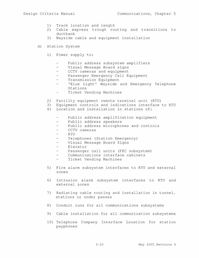
Design Criteria Manual Communications, Chapter 5
5-20 May 2005 Revision 4
1) Track location and length2) Cable express trough routing and transitions to
ductbank3) Wayside cable and equipment installation
d) Station System
1) Power supply to:
- Public address subsystem amplifiers- Visual Message Board signs- CCTV cameras and equipment- Passenger Emergency Call Equipment- Transmission Equipment- "Blue Light" Wayside and Emergency Telephone
Stations- Ticket Vending Machines
2) Facility equipment remote terminal unit (RTU)3) Equipment controls and indications interface to RTU4) Location and installation in stations of:
- Public address amplification equipment- Public address speakers- Public address microphones and controls- CCTV cameras- RTU- Telephones (Station Emergency)- Visual Message Board Signs- Elevator- Passenger call units (PEC subsystem)- Communications interface cabinets- Ticket Vending Machines
5) Fire alarm subsystem interfaces to RTU and externalzones
6) Intrusion alarm subsystem interfaces to RTU andexternal zones
7) Radiating cable routing and installation in tunnel,stations or under passes
8) Conduit runs for all communications subsystems
9) Cable installation for all communication subsystems
10) Telephone Company Interface Location for stationpayphones

Design Criteria Manual Communications, Chapter 5
5-21 May 2005 Revision 4
11) Fire Management Panel
e) Tunnel and Right-of-Way System
1) Tunnel emergency telephones2) Bungalow locations3) Other wayside equipment locations4) Cableway (subway and elevated stations)5) Conduit into stations (subway and elevated)6) Conduit/cableway to signal bungalows and traction7) Electrification substations and tie stations8) Cable route (surface sections)9) Cable installation10) Radiating cable supports and installation (subway)11) Fire Management Panel12) Ventilation system controls and indications
f) Yard and Shop System
1) Power source2) Equipment location3) Radio Subsystem
- Base and control station equipment- Antenna mounting- Radiating cable in buildings
4) Conduit runs for all communications systems5) Cable installation for all communications systems
g) Train Control System
1) CTS Interfaces2) Telephones within bungalows3) ROC control console layout4) Yard Control Tower console layout
h) Traction Power System
1) SCADA Interface to transmission system2) Sectionalizing switch locations (Emergency
telephones)3) Substation telephone locations
i) Operations Control Center Structure System
1) Heating, ventilating and air conditioning2) Power source3) Floor loading4) Lighting
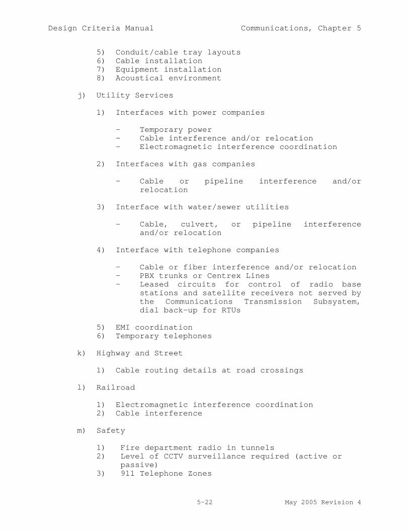
Design Criteria Manual Communications, Chapter 5
5-22 May 2005 Revision 4
5) Conduit/cable tray layouts6) Cable installation7) Equipment installation8) Acoustical environment
j) Utility Services
1) Interfaces with power companies
- Temporary power- Cable interference and/or relocation- Electromagnetic interference coordination
2) Interfaces with gas companies
- Cable or pipeline interference and/orrelocation
3) Interface with water/sewer utilities
- Cable, culvert, or pipeline interferenceand/or relocation
4) Interface with telephone companies
- Cable or fiber interference and/or relocation- PBX trunks or Centrex Lines- Leased circuits for control of radio base
stations and satellite receivers not served bythe Communications Transmission Subsystem,dial back-up for RTUs
5) EMI coordination6) Temporary telephones
k) Highway and Street
1) Cable routing details at road crossings
l) Railroad
1) Electromagnetic interference coordination2) Cable interference
m) Safety
1) Fire department radio in tunnels2) Level of CCTV surveillance required (active or
passive)3) 911 Telephone Zones

Design Criteria Manual Communications, Chapter 5
5-23 May 2005 Revision 4
n) Fare Vending
1) Data Channel Requirements2) Central Fare Collection Location
o) Public Information
1) Information Operators
- Number of Operators- Anticipated Call Volume
p) Airport Authorities (Love Field and DFW InternationalAirport)
1) Radio Frequency Interference2) Security Coordination
q) Regional Transportation Authorities
1) Denton County Transportation Authority2) Trinity Railway Express3) Other Commuter Rail Systems

Design Criteria Manual Communications, Chapter 5
5-24 May 2005 Revision 4
5.6 ABBREVIATIONS AND DEFINITIONS ADA - Americans with Disability Act
Administrative Telephone Subsystem - Used to providecommunications between various DART field facilities andOperations Control Center and communications between DART fieldfacilities and the Public Switched Telephone Network (PSTN).
CCTV - Closed Circuit Television
CELPS - Central Emergency Lighting Power Supply
CIC - Communications Interface Cabinet
CTS - Communications Transmission Subsystem - A bi-directionalfiber optic based digital communications carrier system providinganalog and data connections between the OCC and the field.
CRT - Cathode Ray Tube
DACS - Digital Cross Connect Switch - Software based,microprocessor-controlled digital access and cross-connect systemthat provides for channel swapping of DS-0 slots betweendifferent DS-1 (T1) channels.
DACT - Digital Alarm Communication Transmitters
DACR - Digital Alarm Communication Receiver
dBA - Decibels A filter weighted
Demarcation Panel - The physical interface point betweenfacilities and systems work, which allows the Contractor toindependently consolidate, route and wire copper audio, visual,SCADA and emergency voice circuits from station equipmentlocations back to a central point.
DFW - Dallas-Fort Worth
DID - Direct Inward Dial
DOD - Direct Outward Dial
DTMF - Dual Tune Multi-Frequency
EIA - Electronic Industry Association
E&M - Telephone circuit signaling control lines

Design Criteria Manual Communications, Chapter 5
5-25 May 2005 Revision 4
EMC - Electromagnetic Compatibility - The ability of a device,equipment, or system to function satisfactorily in itselectromagnetic environment without introducing intolerableelectromagnetic disturbances to anything in that environment orbeing affected by the environment in an undesirable way.
EMI - Electromagnetic Interference
FCC - Federal Communications Commission
LCD - Liquid Crystal Display
GRC - Galvanized Rigid Conduit
IMC - Intermediate Metallic Conduit
KHz - Kilohertz
Km - Kilometer
m - meter
Mbs - Megabits
MHz - Megahertz
NEC - National Electric Code
NFPA - National Fire Protection Association
NM - Nanometer
OCC - Operations Control Center - The OCC includes the TrainControl Center (TCC), the Yard Control Center (YCC), the SecurityControl Center (SCC), the Bus Control Center (BCC), and the OCCEquipment Room.
OCU - Office Channel Unit
PA - Public Address
PABX - Private Automatic Branch Exchange
PBX - Private Branch Exchange
PCM - Pulse Code ModulatedPEC - Passenger Emergency Call - A communication system used toallow a passenger in an emergency situation to signal an alarm tothe TCC, open and latch a voice channel and allow TCC personnel

Design Criteria Manual Communications, Chapter 5
5-26 May 2005 Revision 4
to establish two-way communications with the passenger via theCTS.
PTZ - Pan/Tilt/Zoom
PSTN - Public Switched Telephone Network
RTU - Remote Terminal Unit - The equipment that constitutes thefield end of a Data Transmission.
ROC - Rail Operations Controller
ROW - Right-of-Way
S&I - Service and Inspection
SCADA - Supervisory Control And Data Acquisition
SCS - Supervisory Control System
SINAD - Signal Noise and Distortion
SONET OC-3 - Synchronous Optical Network (SONET) - rate of 155.52Mb/s consisting of three (3) multiplexed OC-1 rate channels asdefined by CCITT. The optical signal that corresponds to theSTS-3c electrical signal.
SONET OC-12 - Synchronous Optical Network (SONET) - rate of622.08 Mb/s consisting of twelve multiplexed OC-1 rate channelsas defined by CCITT. The optical signal that corresponds to theSTS-12c electrical signal.
Subsystem - A subsystem comprises elements within a system thatare interconnected to perform a specific function.
TDM - Time Division Multiplex
TPSS - Traction Power Substation
TCC - Train Control Center - Facility located within the OCC thatis staffed and dedicated to the operation, monitoring, andcontrol of the LRT system.
UL - Underwriters Laboratory
UPS - Uninterruptible Power Supply - An auxiliary power systemthat provides an uninterrupted power source during a normal powersource failure.
UPSR - Unidirectional Path Switch Ring

Design Criteria Manual Communications, Chapter 5
5-27 May 2005 Revision 4
VMB - Visual Message Board

CHAPTER 6
TRAIN CONTROL CENTERAND
SUPERVISORY CONTROL SYSTEM

Design Criteria Manual TCC and SCS, Chapter 6
6-i May 2005 Revision 4
Chapter 6
TRAIN CONTROL CENTER AND SUPERVISORY CONTROL SYSTEM
Table of Contents
Section Page
6.1 GENERAL 6-1
6.1.1 Purpose 6-16.1.2 Scope 6-2
6.2 TCC STAFF OPERATING FUNCTIONS 6-2
6.2.1 Mainline Train Supervision 6-36.2.2 Traction Electrification Supervision 6-46.2.3 Communications Equipment Supervision 6-46.2.4 Yard Supervision 6-46.2.5 Coordination with Bus
and Coach Operations 6-56.2.6 Emergency Support 6-56.2.7 Security Monitoring 6-66.2.8 General Coordination 6-6
6.3 TCC PHYSICAL DESCRIPTION 6-7
6.3.1 Train Control Center 6-76.3.2 ROC Consoles 6-86.3.3 Overview Displays 6-96.3.4 Equipment Room 6-96.3.5 Environmental Features 6-106.3.6 Intrusion and
Emergency Services Features 6-10

Design Criteria Manual TCC and SCS, Chapter 6
6-ii May 2005 Revision 4
Chapter 6
TRAIN CONTROL CENTER AND SUPERVISORY CONTROL SYSTEM
Table of Contents
Section Page
6.4 LIGHT RAIL SUPERVISORY CONTROL SYSTEM 6-11
6.4.1 Data Communications between RTUs andthe TCC 6-11
6.4.2 Automated Features 6-126.4.3 Rail Operations Controllers and
Other Users 6-136.4.4 General Graphical Requirements 6-136.4.5 System Response Time Requirements 6-136.4.6 System Availability 6-136.4.7 Remote Terminal Units (RTUs) 6-136.4.7.1 RTU I/O 6-146.4.7.2 Data Communications between RTUs and
the Central Equipment 6-156.4.7.3 Maintainability 6-166.4.7.4 Environmental Requirements 6-166.4.7.5 Enclosures 6-16
6.5 REQUIREMENTS FOR INTERFACE TOOTHER SYSTEMS 6-16
6.5.1 Service and Inspection BuildingSystems Interfaces 6-16
6.5.2 Signal System Interface 6-176.5.3 Traction Electrification System
Interface 6-186.5.4 Station Facilities and
Ventilation System Interfaces 6-19

Design Criteria Manual TCC and SCS, Chapter 6
6-1 May 2005 Revision 4
CHAPTER 6 - TRAIN CONTROL CENTERAND SUPERVISORY CONTROL SYSTEM
6.1 GENERAL
6.1.1 Purpose
The Operations Control Center (OCC) is located at DART's S&IFacility, 3021 Oak Lane, Dallas, Texas, and is also used fordispatch supervision of bus, coach and Transit Police operations.The Train Control Center (TCC) is the principal site for thesupervision of DART rail operations, and is located within theOCC.
The TCC includes radio, public address/visual message board,telephone, and supervisory control system equipment to allow railoperations staff to monitor and control wayside and stationequipment. The TCC equipment includes: a system of Large Screendisplays; Rail Operations Controllers' (ROC) and Yard OperationsController consoles, with voice communications equipment andsupervisory control LCDs; The Yard Operations Controller'sconsole is adjacent to the TCC and is located overlooking theyard area; a DACR to receive all reporting fire alarms, alerts,and system trouble indications communicated through field DACTs(via dialup).
The Equipment Room (ER) is located within the OCC and isseparated from the TCC by the Communications maintenance supportarea. The Equipment room houses the centralized equipment tosupport TCC operational activities. The Equipment Room alsohouses a System’s manager console with voice communicationsequipment.
Data communications facilities and remote supervisory controlsystem equipment are located at stations, tractionelectrification substations, and in communications and signalbungalows.
This chapter:
a) Provides an overview of TCC Light Rail staff operatingfunctions.
b) Provides a description of the TCC area designated forLight Rail operations, and describes architecturalrequirements of the facility.
c) Defines requirements for the Light Rail supervisorycontrol system and equipment.

Design Criteria Manual TCC and SCS, Chapter 6
6-2 May 2005 Revision 4
6.1.2 Scope
The existing TCC space is currently designed to supportsupervision of the Starter System, North East and North CentralExpansion corridors, and the Yard. The TCC will be modified tosupport the increased operational requirements as a result ofadditional expansion corridors. Operational territory will beexpanded by the North West (NW), South East (SE), Irving (IR),and Rowlett (RW) Corridors. The existing Yard will be modified,and a North West Rail Operating Facility (NWROF) will be added.NWROF supervision shall be in accordance with Design CriteriaManual, Volume 2, Chapter 5, Communications, Paragraph 5.4.3.2.
Radio and telephone communications systems and coverage will beexpanded between the TCC and all new revenue operations linesegments.
The supervisory control system shall monitor and control, fromTCC, the following field subsystems in the North West, SouthEast, Irving, and Rowlett line segments:
a) The signal system and associated alarms,
b) The traction electrification system and associatedalarms,
c) Station and tunnel facilities,
d) Communications equipment and associated alarms,
e) Intrusion alarm conditions for station fare collectionequipment.
The supervisory control system shall continue to support allalarm, indication and controls implemented in the Starter System,North Central, and North East Expansion Corridors. Furthermore;additional power requirement, current OCC UPS load and availableload will be analyzed to ensure it can support the future upgradeand modification at TCC and Equipment room.
6.2 TCC Staff Operating Functions
TCC currently includes equipment for radio communications betweenTCC and the Light Rail service area, emergency telephone systemcommunications, alarm and state display from and command input towayside and station equipment via the supervisory control system,public address/visual message board capability, fire subsystemmonitoring and alarming, and administrative telephone connectionsto other DART staff and outside public safety agencies. The

Design Criteria Manual TCC and SCS, Chapter 6
6-3 May 2005 Revision 4
current operating functions will be available in the Light Railservice area to be expanded, i.e., the North West, South East,Irving, and Rowlett Line Sections.
TCC Light Rail operations staff will utilize the equipment toperform operating functions in the following areas:
a) Mainline Train Supervision (Signaling System)
b) Traction Electrification Supervision
c) Communications Equipment Supervision
d) Yard Supervision
e) Coordination with Bus and Coach operations
f) Emergency Support
g) Security Monitoring
h) General Coordination
6.2.1 Mainline Train Supervision
TCC facilities and equipment will be modified as needed to ensurethe following mainline train supervision functions continue toperform per required response times for both the existing systemand Phase II expansion corridors:
a) Supervise single track operation
b) Authorize and monitor special moves such as reverseoperations and early turnback
c) Supervise train operation to schedule
d) Authorize train entry onto mainline
e) Support scheduled and unscheduled mainline maintenanceactivities
f) Designate track as closed or slow/reduced speed
g) Supervise unscheduled mainline coupling and uncoupling
h) Help train operators to troubleshoot vehicle problemson the mainline

Design Criteria Manual TCC and SCS, Chapter 6
6-4 May 2005 Revision 4
i) Record incidents, signal violations, and voice radioand telephone conversations
j) Notify Yard or Maintenance of cars needing maintenance
6.2.2 Traction Electrification Supervision
TCC facilities and equipment will be modified as needed to ensurethe following Traction Electrification Supervision functionscontinue to perform per required response times for both theexisting system and expansion corridors:
a) Control overhead catenary power to support waysidemaintenance and emergency response activities
b) Provide proper power status information in wayside andstation emergencies situations
c) Maintain information on power outages and the times ofoutage and restoration
d) Monitor emergency traction power cutout
6.2.3 Communications Equipment Supervision
TCC facilities and equipment will be modified as needed to ensurethe following Communications Equipment Supervision functionscontinue to perform per required response times for both theexisting system and expansion corridors:
a) Monitor Major and Minor Alarms associated with criticalcommunications equipment used to support DART lightrail operations.
6.2.4 Yard Supervision
TCC facilities and equipment will be modified as needed to ensurethe following Communications Equipment Supervision functionscontinue to perform per required response times for both theexisting system and Phase II expansion corridors:
a) Support pre-dispatch exceptions
b) Supervise car storage and movement
c) Issue Run assignments to train operators
d) Distribute schedule to train operators

Design Criteria Manual TCC and SCS, Chapter 6
6-5 May 2005 Revision 4
e) Distribute bulletins
f) Coordinate car movement to/from Maintenance Area
g) Record voice radio conversations
6.2.5 Coordination with Bus and Coach Operations
TCC facilities and equipment will be modified as needed to ensurerail operations staff can continue to perform the followingfunctions:
a) Reports on major schedule deviations affecting feederoperation and major transfer points
b) Requests for bus, coach and van bridge service
6.2.6 Emergency Support
TCC facilities and equipment will be modified as needed to ensurethe following Emergency Support functions continue to perform perrequired response times for both the existing system and Phase IIexpansion corridors:
a) Monitor Fire Alarms occurring at:
- Traction electrification substations (TPSS)- Signal bungalows and Communications bungalows- Tunnel areas, City Place station, and Aerial
Stations- OCC and Maintenance facilities- Other areas as required
b) In the event of a tunnel fire, control tunnelventilation equipment, and execute EmergencyVentilation Scenarios.
c) Access and follow pre-defined emergency procedures andinformation.
d) Coordinate emergency response activities with the FireDepartment and other public emergency services using911, Radio, and Emergency Telephones
e) Generate Public Address and Visual Messages to thePatrons located within the usable limits of StationPlatforms and Underpasses.
f) Communicate with Emergency and Wayside Telephones.

Design Criteria Manual TCC and SCS, Chapter 6
6-6 May 2005 Revision 4
g) Monitor fire suppression equipment failures
h) Monitor tunnel and station sump pumps
i) Monitor Fire Management Panel usage
j) Support testing of fire alarms
k) Support testing of fans and dampers
l) Monitor status of primary power and UPS for station,tunnel ECS, and Communications equipment
6.2.7 Security Monitoring
TCC facilities and equipment will be modified as needed to ensurethe following security related functions continue to perform perrequired response times for both the existing system andexpansion corridors:
a) Monitor intrusion alarms from station fare collectionequipment, signals and TPSSs bungalows, communicationsequipment rooms and bungalows, station facilitiesincluding Knox-boxes, and other required wayside areas
b) Monitor intrusion gate alarms at tunnel stationentrances
c) Support testing of intrusion alarms
6.2.8 General Coordination
TCC facilities and equipment will be modified as needed to ensurethe following functions are available for both the existingsystem and Phase II expansion corridors:
a) Provide voice communications patches as appropriate
b) Monitor status of Light Rail subsystems equipment andreport abnormal conditions to Maintenance
c) Monitor status of Light Rail facilities and reportabnormal conditions to Maintenance
d) Maintain a log of:
- Systems-related events- Facilities-related events

Design Criteria Manual TCC and SCS, Chapter 6
6-7 May 2005 Revision 4
6.3 TCC PHYSICAL DESCRIPTION
The Train Control Center (TCC) at the S&I facility is used forsupervision of mainline and yard Light Rail operations andincludes a Light Rail overview display system and individualconsoles for the rail operations staff. The Equipment Room atthe S&I facility houses supporting systems equipment including:voice and data communications controllers, field interfaceequipment, and supervisory control computers and peripheraldevices.
6.3.1 Train Control Center
The TCC will house any new communications and supervisory controlconsoles used by Rail Operations Controllers (ROCs) and theChief. It will also include any expansion to the existing Wallformat Overview Displays.
A future Commuter Rail Controller may also be located in the TCC.Future security staff, responsible for monitoring CCTV andresponding to patron emergency calls, will be located elsewherein the S&I facility.
Additional consoles and supporting equipment shall be added tosupport the operational requirements of the system expansion. TheTCC shall be modified as needed to contain up to six ROCconsoles.
The consoles for operational staff shall be located to facilitatecommunications among the staff. The following additionalconditions shall be met:
a) The ROC consoles shall be arranged for effectiveoperation with up to six manned.
b) All ROC consoles shall be located to have a good viewof an Overview Display. Staff manning the consolesshall be able to see the Overview Display while seatednormally at the console, with horizontal angular rangenot exceeding 70 degrees and vertical angle notexceeding 30 degrees. Each shall be close enough toeasily discern the Overview Display legends andsymbols.
c) Access to the TCC shall be located to minimize thedisturbance to staff communications or their view ofthe Overview Display.

Design Criteria Manual TCC and SCS, Chapter 6
6-8 May 2005 Revision 4
6.3.2 ROC Consoles
All new ROC consoles shall be similar in Aesthetic Appearance tothe existing Consoles. Performance Requirements shall meet orexceed that of the existing consoles. Consoles shall have thefollowing design requirements:
a) Console dimensions shall be selected consistent withergonomic limits
b) Frequently used equipment shall be located mostaccessibly. Most-frequently used procedures shallrequire the fewest actions possible. Equipmentlocation shall relate to the normal flow of staffactivities.
c) Single purpose function buttons and switches shall beused for, but limited to, functions which arefrequently used or require rapid activation.
d) Voice communications interfaces shall be integratedsuch that staff need not switch between more than twodevices to interact with the several parties with whomthey may need to maintain contact.
e) Choice of command entry devices shall consider theimpact upon staff and of other activities (e.g., voiceactuation vs. other verbal activities, frequency andduration of arm extension for touch panel or cursordevice, motion accuracy requirements).
f) LCD's shall be sized consistently with informationrequirements and density to minimize emission exposure.LCD's shall be high resolution, low flicker. Colorcapabilities shall be consistent with informationrequirements.
g) Audio outputs shall have volume controls. LCD's shallhave easily accessible intensity and color controls.
h) Horizontal surfaces, which are touched by operators,shall be non-metallic (low thermal conductivity).Edges shall be rounded.
i) Assemblies and wiring shall be modular to allowreplacement of a failed unit within thirty minutes, andreplacement shall not require shutdown of thefunctioning portion of the console. Interface devicesshall utilize plug connectors or equivalent forconvenient device replacement.

Design Criteria Manual TCC and SCS, Chapter 6
6-9 May 2005 Revision 4
6.3.3 Overview Displays
The existing Overview Displays will be used for the StarterSystem, North Central, and North East Corridors. AdditionalOverview Display Equipment will be specified to supportoperational requirements associated with the expansion corridors.The Overview Display equipment shall display an overview ofsystem status sufficient for Rail Operations Controllers tointegrate information regarding: blocks of signaled track wheretrains are located, traction electrification system status, andcritical alarm conditions. The following specific physicalfeatures shall be provided:
a) Display of multiple simultaneously displayed colors andobject display attributes (including flashing).
b) Display legends shall be easily read from ROC consoles.Abbreviations shall be permitted in legends.
c) The display equipment shall be maintainable withminimal disruption to operations.
d) Display intensity and room lighting levels shall beconsistent with easy visibility over long periods.
6.3.4 Equipment Room
The Equipment Room (ER) is located within the OCC and isseparated from the TCC by the Communications maintenance supportarea. The Equipment room houses the centralized equipment tosupport TCC operational activities. The Equipment Room alsohouses a System’s manager console with voice communicationsequipment. The following Equipment is currently housed within theEquipment Room:
a) A Redundant Optical Add/Drop SONET Multiplexer
b) TCC Local Area Network Equipment
c) A Digital Cross Connect System
d) Channel banks
e) Fiber optic cable termination equipment
f) Main Distribution Frame (MDF)

Design Criteria Manual TCC and SCS, Chapter 6
6-10 May 2005 Revision 4
g) A Communications Controller and associated equipment tosupport Voice, Radio, and PA/VMB communications by theoperators
h) Radio voting equipment
i) Audio recorders
j) Supervisory Control System Equipment
k) Test equipment storagel) Documentation storage for equipment and software
m) Work area for technicians
The Existing Equipment Room layout shall be modified as needed tosupport additional equipment requirements as a result of thePhase II expansion.
6.3.5 Environmental Features
The following environmental features shall be considered whenmodifying the TCC and Equipment Room with additional equipment:
a) Controls and air conditioning equipment capacity shallbe sufficient to maintain room temperatures within therange of 65 to 75 degrees Fahrenheit (within .5degrees) and within a relative humidity of 60 to 80percent.
b) All work areas shall be illuminated. The TCC shallhave general lighting that can be dimmed and controlledfrom a central location. In addition, spot lightingshall be provided for all consoles. All generallighting shall be connected to Essential Power.
6.3.6 Intrusion and Emergency Services Features
Modifications to the TCC and Equipment Room shall not diminishexisting Emergency services. The following emergency servicefeatures shall continue to be supported:
a) TCC and Equipment Room access control provided withlocked doors.
b) A fire alarm system and/or clean agent fire suppressionsystem for the Equipment Room and the TCC, withoverriding shutoff.

Design Criteria Manual TCC and SCS, Chapter 6
6-11 May 2005 Revision 4
c) Emergency egress systems. These include flashinglights, unlocking power doors, etc., sufficient toensure occupants will have clear exit routes.
6.4 LIGHT RAIL SUPERVISORY CONTROL SYSTEM
The existing Light Rail Supervisory Control System (SCS)automates and/or augments some of the functions for LRToperations. The SCS is computer-based and includes equipment atthe TCC, Equipment Room, communication and signal houses,Traction Power Substations, Light Rail stations, and other fieldlocations.
The major elements of the SCS are:
a) Remote terminal units (RTUs) located along the waysideto acquire devices and alarm states and to implementROC device control commands.
b) Computer equipment located at the TCC, the OverviewDisplay, and ROC console-based display and inputdevices. Display devices provide up-to-date wayside,station, and alarm information.
6.4.1 Data Communications between RTUs and the TCC
A fiber optic communications system is currently in place betweenTCC and the following line segments of the system:
a) Oak Cliff not including SOC and WOC
b) North Central
c) North East
A fiber optic communications system shall be provided between TCCand the following line segments of the system:
a) North West
b) South East
c) Irving
d) Rowlett

Design Criteria Manual TCC and SCS, Chapter 6
6-12 May 2005 Revision 4
Fiber optic-based communications is also provided between TCC andthe traction electrification substations in the CBD and OC linesections, not including WOC and SOC.
The RTUs in the expansion line segments and the TCC computerequipment shall communicate over the fiber optic communicationssystem utilizing industry-standard physical level and link leveldata communications protocols.
6.4.2 Automated Features
The SCS shall continue to provide the following automatedfeatures for the expansion:
a) Monitor and report to the ROCs change-of-state for:
- Signal system devices and alarms
- Traction electrification system devices and alarms
- Station Fare Collection equipment intrusion alarms
- Fire alarms, station facility alarms, stationalarms, and tunnel ventilation system devices andalarms
- Security/intrusion detection device alarms
- Communications equipment alarms
b) Keep current all displayed information on the OverviewDisplay and console LCD displays.
c) Initiate control actions to station and wayside devicesin response to ROC commands entered at the ROCconsoles. Control actions shall include those to:
d) Control traction electrification system breakers andmotorized disconnect switches
e) Control emergency traction power disconnect
f) Control ventilation system fans and dampers in responseto tunnel fires
g) Control signal equipment
h) Request routes of signal system vital interlockings

Design Criteria Manual TCC and SCS, Chapter 6
6-13 May 2005 Revision 4
i) Operators can place track blocks on segments of tracksfor indication only, but there will be no impact in thefield.
j) Recall and display emergency operating procedures andrecommended ventilation scheme for response to tunnelfires
k) Log system events, alarms, and operator-enteredcommands
6.4.3 Rail Operations Controllers and Other Users
Rail operations staff shall continue to utilize ROC consoles tosupervise Light Rail system activities. All new ROC consolesshall be similar to existing consoles, and shall meet or exceedthe performance characteristics of the existing consoles.
6.4.4 General Graphical Requirements
The new Overview Display and console graphics for the expansionsshall provide a semi-geographic representation of the Light Railsystem and its major subsystems. All displayed information,symbols, and associated graphics shall be consistent with thecurrent implementation.
6.4.5 System Response Time Requirements
The elapsed time from:
a) First possible detection by an RTU of an alarm ordevice change of state until display at TCC shall notexceed four (4) seconds.
b) When an ROC enters a command for any individual devicecontrol until the RTU generates the associated outputsignal shall be no more than four (4) seconds.
6.4.6 System Availability
The Supervisory Control System is intended to operate 24 hoursper day seven days a week. Modifications to the SCS architectureshall not compromise system availability.
6.4.7 Remote Terminal Units (RTUs)
RTU equipment is located within communications and signalbungalows along the wayside, and in traction electrification

Design Criteria Manual TCC and SCS, Chapter 6
6-14 May 2005 Revision 4
system (TES) bungalows. Additional RTUs shall be provided tosupport expansion corridors. RTUs:
a) Provide device signal state acquisition, change ofstate detection, and corresponding reporting to centralcomputer equipment
b) Initiate device control actions based on commands fromcentral computer equipment
c) Provide alarm signal acquisition and correspondingreporting to central computer equipment
d) New RTUs shall be solid-state microprocessor-basedunits with logic elements and auxiliary componentsconfigured as easily replaceable plug-in modules. Allcommunications RTUs shall be from the samemanufacturer; common function subsystem modules shallbe interchangeable between the RTUs.
e) RTU configuration shall be modular to provide expansionof performance and capacity by adding subsystemmodules. This shall include the ability to add I/Osubsystem modules.
f) RTUs shall be capable of unattended operation. RTUsshall automatically begin operation upon power on.
g) Each RTU shall be capable of continued operation withthe loss of communication to TCC as a result of eithercommunication equipment failures or central equipmentfailures. Each RTU shall, in the event of loss ofpower, perform auto-restart after resumption of power.
h) RTUs shall support local initialization andtroubleshooting with either local control panel orportable test equipment.
6.4.7.1 RTU I/O
RTUs shall support digital inputs and outputs via contact closureand relays (or optically isolated solid state equivalents such assilicon controlled rectifiers). I/O shall be electricallyisolated to protect against power surges.
Input and output circuit wiring shall be terminated at terminalblocks, where they will be connected to device indication orcontrol circuit wiring provided by others.
For inputs:

Design Criteria Manual TCC and SCS, Chapter 6
6-15 May 2005 Revision 4
a) The RTU shall provide DC voltage to an input circuit tosense contact closure
b) Each input circuit shall be scanned such that allevents lasting at least 500 milliseconds are acquired
c) Abnormal or inaccurate sensing conditions due to signalbounce and power transients shall be accommodated
For outputs:
a) The RTU shall provide and drive a relay and dry contact
b) Each digital output shall be controlled by software toclose for a specific time length; the length of timeshall be pre-defined (and configurable) for each pointto be between 100 milliseconds and 2 seconds.
c) The RTU shall prevent unintended energizing of outputcircuits upon power up and power restoration.
LED indicators shall be provided on the front of each I/O cardindicating the current status i.e., input contact closed, outputrelay energized.
RTU I/O subsystems (including cables) shall be equipped withextra capacity for both input and outputs.
6.4.7.2 Data Communications between RTUs and the CentralEquipment
RTUs shall utilize an Ethernet connection to the fiber opticcommunications system to communicate with the TCC. Speed shallbe at least 10 Mbps and as much as 100 Mbps. Signal System RTUsshall be interfaced serially to the Communication Systems RTU.Error correction and detection shall utilize an industry standardscheme (such as CCITT CRC-16) and at a minimum shall: detect allerrors of up to 16 contiguous bits; and detect at least 99% ofall error bursts greater than or equal to 16 bits.
For RTU locations where the fiber optic communications system isnot present, the RTU shall communicate with the TCC using a dial-up telephone line.

Design Criteria Manual TCC and SCS, Chapter 6
6-16 May 2005 Revision 4
6.4.7.3 Maintainability
RTUs shall:
a) Perform self-tests upon power up and on command fromlocal test equipment and from central. I/O subsystemsand I/O cards shall also perform self-tests.
b) Detect and report I/O subsystem card failures andindicate via card LEDs
c) Detect and indicate (via local LED) lack ofcommunication link
d) Provide for safe maintenance and testing of I/Ocircuits and safe replacement of I/O cards while poweris applied to the RTU and I/O subsystem.
e) Include and support use of portable test units whichcan:
- Emulate RTU to the TCC- Emulate the TCC to the RTU
6.4.7.4 Environmental Requirements
RTUs shall be capable of continued operation between -10C and+60C with up to 95% humidity (non-condensing)
RTUs shall be capable of continued operation in theelectromagnetic environment where they will be located, such asTES, signal, and communications bungalows. RTU electromagneticemissions shall meet FCC requirements.
6.4.7.5 Enclosures
RTUs shall be located in racks or cabinets. Racks, Cabinets, andequipment shall be properly grounded.
I/O cables shall be labeled and shall have keyed plug connectorsfor connection to I/O cards.
6.5 REQUIREMENTS FOR INTERFACE TO OTHER SYSTEMS
6.5.1 Service and Inspection Building Systems Interfaces
The S&I building shall provide the following support interfaces:
a) Building Power

Design Criteria Manual TCC and SCS, Chapter 6
6-17 May 2005 Revision 4
- The building facilities provide Essential Powerand House Power for the current loads.
- Additional power loads will be calculated toaccount for any added equipment. Requirementsshall be communicated to building facilities forpossible expansion.
b) Grounding Interface
- The building facilities have provided existinggrounding systems. The TCC system equipmentutilizes two independent grounding systems. Thegrounding systems shall have connection points inthe Equipment Room and the TCC.
- The current grounding system shall be evaluatedand modified to support any additional connectionsrequired.
6.5.2 Signal System Interface
The signal system shall continue to provide portions ofindication and control circuitry to enable the RTUs to:
a) All signal system Local Control Panel control, alarm,and Terminal Mode functions shall be available on theshall be available at the TCC and OCS
b) Monitor and report signal system power alarmconditions, e.g.: conditions caused by events such asblown fuse, ground detection, AC and DC power failures
c) Monitor and report state for signal system devices suchas: track circuits/blocks, switches, signals andplatform limits.
d) Monitor and report fire alarms at signal bungalows
e) Request track inhibit (to prevent train entry intoclosed track), and request track inhibit reset
f) Request switch inhibit (to prevent realignment of aswitch), and request switch inhibit reset
g) Request routes of interlockings, including routes insupport of reverse train movement
h) Support testing of signal bungalow fire alarms

Design Criteria Manual TCC and SCS, Chapter 6
6-18 May 2005 Revision 4
The Signal System shall provide one or more terminal blocks towhich RTU I/O wiring can be connected, and shall provide and wirecircuitry between the terminal block and its devices.
The signal bungalows shall contain sufficient space for anRTU/Communications cabinet, and shall provide sufficient powerfor the RTU and supporting devices.
6.5.3 Traction Electrification System Interface
The Traction Electrification System shall provide portions ofindication and control circuitry to enable the RTUs to:
a) Monitor and report TES alarm conditions, e.g. caused byevents such as: high substation temperature; hightransformer temperature; uninterrupted power systemfault
b) Monitor and report change-of-state for tractionelectrification system:
- AC feeder breaker- AC over/under voltage and over current- DC over/under voltage and over current- DC rate of rise
c) Monitor and report change-of-state (energized/de-energized status) of OCS sections
d) Monitor and report if a circuit breaker has been placedin local control mode
e) Monitor and report Blue Light station local lockoutstate, and support testing of emergency traction powerdisconnect from Blue Light stations
f) Monitor and report fire alarms at TESs
g) Command open and/or close of DC and AC circuit breakers
h) Command disconnect/restoration of DC power to acatenary section
i) Support testing of TES bungalow fire alarms
j) Monitor presence of voltage indication on station Bussand catenary sections

Design Criteria Manual TCC and SCS, Chapter 6
6-19 May 2005 Revision 4
The TES shall provide one or more terminal blocks to which RTUI/O wiring can be connected, and shall provide and wire circuitrybetween the terminal block and its devices.
The TES substation bungalows shall contain sufficient space foran RTU/Communications cabinet, and shall provide sufficient powerfor the RTU and supporting devices.
6.5.4 Station Facilities and Ventilation System Interfaces
Station facilities and ventilation system shall provide portionsof indication and control circuitry to enable the RTUs to:
a) Monitor and report fire/smoke alarms in:
- Tunnel areas and underground station(s)- Aerial Stations
b) Monitor and report activation of local Fire ManagementPanels at tunnel areas and underground station(s)
c) Monitor and report change-of-state for ventilationequipment (fans and dampers) in tunnel areas andunderground station(s)
d) Monitor and report station high temperature alarms,e.g., in equipment rooms, bungalows, interface cabinets
e) Monitor and report alarm conditions for stationenvironmental control equipment:
- Fire water pump (low water level)- Sprinkler system- Air conditioning system
f) Monitor and report high water alarm state from tunnelsump pumps
g) Monitor and report station power-related alarms:
- Primary AC feed and circuit breaker- Station UPS (transfer to/failure)
h) Monitor and report fare vending equipment intrusionalarms
i) Monitor and report intrusion alarms at selected areas
j) Issue "test" control to fire alarms in:

Design Criteria Manual TCC and SCS, Chapter 6
6-20 May 2005 Revision 4
- Tunnel areas- Non-tunnel areas
k) Control ventilation fans and dampers in tunnel andunderground station areas
The station facilities, station environmental control system, andventilation system shall provide one or more terminal blocks ineach communications equipment room to which RTU I/O wiring can beconnected, and shall provide and wire circuitry between theterminal block and its devices.
The station communications equipment rooms shall containsufficient space for and RTU/Communications cabinet, and shallprovide sufficient power for the RTU.

CHAPTER 7
FARE COLLECTION

Design Criteria Manual Fare Collection, Chapter 7
Chapter 7
FARE COLLECTION
Table of Contents
Section Page
7.1 GENERAL 7-1
7.2 TICKET VENDING MACHINES 7-1
7.2.1 Coin and Bank Notes 7-27.2.2 Ticket Stock 7-37.2.3 User Information 7-37.2.4 Display Features 7-37.2.5 Additional TVM Features 7-37.2.6 TVM Dimensions 7-4
7.3 TICKET VENDING MACHINE HARDWARE REQUIREMENTS 7-5
7.3.1 Equipment Enclosure 7-67.3.2 Lighting 7-77.3.3 Utility Connections 7-7
7.4 RELIABILITY AND MAINTAINABILITY 7-7
7.5 SECURITY 7-7
7.6 CENTRALIZED DATA COLLECTION SYSTEM 7-8
7.7 VALIDATORS 7-9
7-i May 2005 Revision 4

Design Criteria Manual Fare Collection, Chapter 7
CHAPTER 7 - FARE COLLECTION
7.1 GENERAL
The DART Light Rail (LRT) Fare Collection System consists of farecollection equipment and a related Centralized Data CollectionSystem (CDCS).
The fare collection equipment for the Light Rail Buildout Phase 2System shall use the barrier-free, self-service method. The farecollection equipment shall have been proven in transit revenueservice.
Each station shall have fare collection equipment consisting ofone or more ticket vending machines (TVM) , and one or more StandAlone Validators (Validators). Each TVM shall have the capabilityto vend single-ride and day pass tickets, of various pricinglevels. The TVM shall issue tickets already validated or notvalidated. Validators shall validate pre-purchased tickets bystamping an inserted ticket with current date, issue time, and avalidator code.
Transit patrons shall purchase tickets, validate them ifnecessary, and retain the validated tickets as evidence of paymentfor passage throughout the system.
The fare collection equipment shall be designed to meet applicablestandards such as the National Electrical Code (NEC), NationalElectrical Safety Code (NESC), and Underwriters' Laboratories,Inc. (UL), and the local codes of authorities having jurisdiction.
The fare collection equipment shall be designed to meet the rulesin Title 49, Code of Federal Regulations, Part 37 resulting fromthe Americans with Disabilities Act. In particular, rules relatedto Automated Teller Machines (49CFR37, Appendix A, Section 4.34)and appended guidelines for Controls and Operating Mechanisms(Appendix Section A4.27) must be addressed in the fare collectionequipment design.
7.2 TICKET VENDING MACHINES
TVMs shall:
a) Dispense tickets according to fare policy
b) Accept U.S. coins for payment
c) Accept U.S. bills for payment
d) Have a display to provide information to patrons thatis fully visible in direct sunlight
e) Meet all applicable requirements of ADA
f) Have buttons that allow Patrons to make choicesregarding language, zones, type and quantity of tickets
g) Recirculate coins
7-1 May 2005 Revision 4

Design Criteria Manual Fare Collection, Chapter 7
h) Have supplemental change units
i) Accept overpayments and issue overpayment tickets
j) Have cancel button
k) Allow purchase of multiple tickets in a singletransaction
1) Meet the temperature requirements of the localenvi ronment
7.2.1 Coin and Bank Notes
The TVM shall accept, validate and retain only United Statescoins.
a) Coins accepted and validated shall only include:Dollar coinsFifty-cent coinsQuartersDimesNickels
b) The coin validator shall be configurable to accept anAuthority defined token.
c) The TVM shall return change.
d) The coin system shall consist of:
Coin re-circulation unit capable of handling allabove coin denominations with the exception ofFifty-cent coins.1) Receptacle capacity of 70 coins per unit
Coin escrow units that return the exact same coinsdeposited during that transaction.1) Minimum size based upon the re-circulation
unit
Supplemental change units1) Minimum capacity of 700 coins
Coin Vaults1) Minimum size of 366 cubic inches2) Weight not to exceed 10 pounds empty
e) Any component of the coin system shall be removableand, when removed, the TVM shall remain in service forbank note transactions.
The TVM shall accept, validate, and retain only United States banknotes.
7-2 May 2005 Revision 4

Design Criteria Manual Fare Collection, Chapter 7
Bank Note capability shall include the following:a) One dollarb) Five dollarc) Ten dollard) Twenty dollar
Accepted bank notes shall be stacked and stored separate and apartfrom the coinage in a locked vault.
a) Minimum capacity of 1,000 billsb) Weight not to exceed 10 pounds empty
Bank notes shall be accepted in all four orientations.
The bill validator shall reject foreign objects and all bank notesnot in acceptable condition.
The bill system shall be removable and, when removed, the TVMshall remain in service for coin transactions.
The TVM shall contain a bill escrow unit that holds up to 15bills.
7.2.2 Ticket Stock
The TVM shall dispense ticket stock as follows:
a) Minimum of four (4) unique ticket stocks.
7.2.3 User Information
Each TVM shall facilitate ticket purchase by:
a) Logically arranged step-by-step ticket purchaseinformation
b) Presenting information in the following forms:American EnglishSpanishInformation that complies with Title 49, Code ofFederal Regulations Part 37
7.2.4 Display
The TVM shall contain a patron user display device and the displaydevice shall provide information necessary to purchase ticket(s).
7.2.5 Additional TVM Features
The additional following TVM features shall be provided:
a) Cancel Button - To immediately cancel the transactionand return any coins or bills that are held in escrow.
7-3 May 2005 Revision 4

Design Criteria Manual Fare Collection, Chapter 7
b) Automatic Time-Out - If a transaction is not completedwithin a preset time, the TVM shall cancel the currenttransaction and prepare for the next transaction.
c) Recording of Transactions - The TVM shall record eachand every transaction. As a minimum the following datashall be recorded:
DateTimeEvent codeEmployee codeTotals for each ticket type selectedTotal transaction valueOverpaymentsAll Maintenance and Revenue access and the actionstaken.Count by bill and coin type received for allvaults and hoppers.
d) Programming Capabilities - The TVM shall have thecapability to be programmed by authorized servicepersonnel to modify the ticket printed and to updatethe fares associated with each button.
e) Authorized service personnel shall have thecapability to modify (through the CDCS) the maximumchange returned.
f) Authorized service personnel shall have thecapability to modify (through the CDCS) the banknotes denominations accepted.
g) An audit register ticket showing vaulted money shallbe created for counting room audit purposes.
h) Environmental - The TVM must be suitable for outdooroperation in exposed locations under the full rangeof climatic conditions as detailed in the DesignCriteria Manual. Volume 2, Systems, Chapter 1.
i) Ergonomic Factors - Design for:
Optimized human factors performancePatron information and instructionsTicket purchasing methods and operationsRevenue and ticket stock servicingTVM maintenance servicing
7.2.6 TVM Dimensions
7-4 May 2005 Revision 4

Design Criteria Manual Fare Collection, Chapter 7
Overall TVM dimensions above mounting base:
Width: 3ft - OinDepth: 2ft - Oin
Range of operable control: In accordance with ADArequirements
Cabinet overhang: Not lower than 8OinAccess: Wheel chair front and side
7.3 TICKET VENDING MACHINE HARDWARE REQUIREMENTS
The TVMs shall be constructed of modular components that providefor ease of maintenance and servicing, including:
a) Modular hardware design
b) Lowest level replaceable unit modules
c) Provide module exchange method for machine servicingfrom the front
d) A coin slot with verifier and escrow unit to validatethe coins used as payment.
e) Coin re-circulating unit:Allows current use of inserted coins for making ofchange.Requires the change to come from the re-circulating unit until it is empty.Whenever the re-circulating unit cannot dispensechange, then change shall be dispensed from thesupplemental change units.
f) Coin vaults for:Receiving coinsSecuring coins
g) Integrated bill acceptance system:Bank note acceptor and verifierEscrow unit
h) Bill vaults with stackers for:Receiving bank notesSecuring bank notes
i) The coin and bill vaults shall be uniquely keyed and:Be protected so that they can only be opened byauthorized personnel in the counting room.Have an exclusive, secured chamber in the TVMassembly or pedestal.
7-5 May 2005 Revision 4

Design Criteria Manual Fare Collection, Chapter 7
j) A ticket tray for:Ticket dispensingReturning change
k) Microprocessor logic for:Controlling the machineMonitoring its condition
1) Data shall exit the machine by way of fiber optic cablestubbed up into the TVM base.
m) Power Backup to:Complete the last ticket transaction if money hasalready been inserted.Ensure that the data is keep intact so that eventsmay be tracked.Maintain the local alarm for at least four hours.
n) Provide for a local shut-off for the local alarm.
o) A security system as described in Paragraph 7.5,Security
p) Sufficient memory capacity to electronically retain alltransactional data for replacement of hard drive orsubsequent transmittal to data storage facility:
ASCII data formatRemovable memory device (i.e. PCMCIA card orfloppy)
q) Remote monitoring and reporting over the communicationsnetwork.
r) The TVM may include:Bank credit/debit card reader/validatorCredit card reader/validator
7.3.1 Equipment Enclosure
The TVM cabinet characteristics shall include the following:
a) Constructed from stainless or cold-rolled, commercial-quality steel.
b) Provide front access
c) Be free of sharp edges and burrs on all exteriorsurfaces including all controls and appurtenances.
d) Built to resist damage to exterior cabinet andcomponents due to abuse and vandalism and shall furtherprotect all accessible components of the machine from
7-6 May 2005 Revision 4
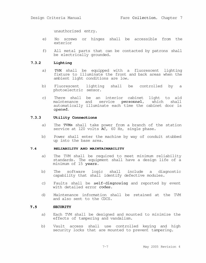
Design Criteria Manual Fare Collection, Chapter 7
unauthorized entry.
e) No screws or hinges shall be accessible from theexterior
f) All metal parts that can be contacted by patrons shallbe electrically grounded.
7.3.2 Lighting
a) TVM shall be equipped with a fluorescent lightingfixture to illuminate the front and back areas when theambient light conditions are low.
b) Fluorescent lighting shall be controlled by aphotoelectric sensor.
c) There shall be an interior cabinet light to aidmaintenance and service personnel, which shallautomatically illuminate each time the cabinet door isopened.
7.3.3 Utility Connections
a) The TVMs shall take power from a branch of the stationservice at 120 volts AC, 60 Hz, single phase.
b) Power shall enter the machine by way of conduit stubbedup into the base area.
7.4 RELIABILITY AND MAINTAINABILITY
a) The TVM shall be required to meet minimum reliabilitystandards. The equipment shall have a design life of aminimum of 15 years.
b) The software logic shall include a diagnosticcapability that shall identify defective modules.
c) Faults shall be self-diagnosing and reported by eventwith detailed error codes.
d) Maintenance information shall be retained at the TVMand also sent to the CDCS.
7.5 SECURITY
a) Each TVM shall be designed and mounted to minimize theeffects of tampering and vandalism.
b) Vault access shall use controlled keying and highsecurity locks that are mounted to prevent tampering.
7-7 May 2005 Revision 4

Design Criteria Manual Fare Collection, Chapter 7
c) All exterior doors shall be locked with at least athree-point latching device with a bascule bolt and ahook locking bar, or DART approved equivalent.
d) Access to the TVM for maintenance functions shall notprovide access to the money vaults.
e) The TVM shall detect intrusions and shall signal theTrain Control Center (TCC) via the LRT Systemcommunications network.
f) In the event the door on the TVM should be openedwithout proper authorization, an audible alarm shallannunciate this condition locally at the machine andimmediately send the alarm message to the CDCS and tothe TCC.
g) The communications link integrity shall beautomatically checked on a periodic basis to confirmthat it is functional.
7.6 CENTRALIZED DATA COLLECTION SYSTEM
a) The TVMs shall be networked together for informationtransfer between the CDCS and each TVM installed.
b) The CDCS provides:Transaction record integrity when moving data fromthe TVM to the Data Storage Computer.Daily TVM polling to ensure transmittal of datafrom the TVM to the CDCS.Data repository for all event and transactionaldata.Control of various TVM operating parameters from aremote location to allow new system files to besent to the TVMs.A vehicle to generate required system reports.
c) The CDCS shall receive status indication from the TVMvia the communications network.
d) At a minimum, the following TVM originated informationshall be transmitted to the CDCS:
Intrusion Alarm Data1) Machine identification number2) Event code triggered3) Date and timeTransaction Data1) Machine identification number2) Date and time3) Overpayment amount4) Escrow amount
7-8 May 2005 Revision 4

Design Criteria Manual Fare Collection, Chapter 7
5) Card number6) Ticket information
i. Typeii. Valueiii. Quantities
e) Event DataMachine identification numberDate and timeEvent codeAccess information
f) Revenue Container Insertion and RemovalData Machine identification numberDate and timeRevenue container identificationEmployee ID
7.7 VALIDATORS
a) Validators shall:Be stand-alone devicesImprint an inserted ticket with:1) Date2) Ticket expiration time3) Station4) Validator identification code
b) Imprint marks shall be clearly visible on the ticket.
c) Approximate validator dimensions excluding its mountingpost or ventilating hood shall be:
Height: 27inWidth: 14inDepth: 14in
d) Range of operable control:In compliance with ADA requirements
7-9 May 2005 Revision 4

CHAPTER 8
CORROSION CONTROL

Design Criteria Manual Corrosion Control, Chapter 8
8-i May 2005 Revision 4
Chapter 8
CORROSION CONTROL
Table of Contents
Section Page
8.1 GENERAL 8-1
8.1.1 Purpose 8-18.1.2 Transit System Description 8-18.1.3 Scope 8-18.1.4 Interfaces 8-28.1.5 Expansion Capability 8-2
8.2 SOIL CORROSION CONTROL (BURIED STRUCTURES) 8-2
8.2.1 Purpose 8-28.2.2 Scope 8-38.2.3 Design of Soil Corrosion Prevention 8-3
Systems8.2.4 Materials and Structures 8-7
8.3 STRAY CURRENT CORROSION CONTROL 8-11
8.3.1 General 8-118.3.2 Scope 8-128.3.3 Traction Power System 8-128.3.4 Water Drainage and Infiltration 8-168.3.5 DART Fixed Facilities 8-178.3.6 Utility Structures 8-198.3.7 Facilities Owned By Others 8-20
8.4 ATMOSPHERIC CORROSION PREVENTION 8-21
8.4.1 Purpose 8-218.4.2 Scope 8-218.4.3 Design of Atmospheric Corrosion 8-22
Prevention Systems

Design Criteria Manual Corrosion Control, Chapter 8
8-1 May 2005 Revision 4
CHAPTER 8 - CORROSION CONTROL
8.1 GENERAL
8.1.1 Purpose
This chapter describes design requirements necessary to providecorrosion control for DART LRT System. Corrosion control systemsshall: prevent premature corrosion failures; minimize straycurrent effects on DART owned and other underground structures;and be economical to install, operate, and maintain.
8.1.2 Transit System Description
Traction power for transit vehicles is supplied by a nominal750-volt DC overhead catenary system. The catenary system isenergized by Traction Power Substations located along systemroute. The running rails of each track are used as negativeconductors for the return of traction power to substations. Thesystem operates on fixed facilities, such as aerial and at-gradetrackway facilities. Negative return rails are crossbonded atapproximately 2000 ft. intervals to maintain electricalcontinuity and equal potential levels for all rails.
8.1.3 Scope
Corrosion control design criteria encompass all engineeringdisciplines applied to the project. The criteria is separatedinto three areas: Soil Corrosion, Stray Current Corrosion andAtmospheric Corrosion Controls. The criteria for each aredescribed below:
a) Soil Corrosion Control. Criteria shall apply tosystems or measures installed to mitigate corrosioncaused by soils and ground waters. Designs shall bebased on the corrosive characteristics of soils asdocumented in the predesign investigations report orfrom actual on-site measurement, if necessary. Thereport shall be used by the designer to aid with thedesign and preparation of construction contractdocuments.
b) Stray Current Corrosion Control. Criteria shall applyto systems or measures installed with the tractionpower system and trackwork to assure that stray earthcurrents are maintained within acceptable ranges basedon system characteristics and the characteristics ofother underground facilities.

Design Criteria Manual Corrosion Control, Chapter 8
8-2 May 2005 Revision 4
c) Atmospheric Corrosion Control. Criteria shall apply tosystems or measures installed to mitigate corrosioncaused by local climatological conditions and airpollutants. Design shall be based on the corrosivecharacteristics of the atmosphere as documented in thepredesign investigations report. The report shall beused to aid with the design and preparation ofconstruction contract documents.
8.1.4 Interfaces
Corrosion control engineering shall be interfaced andcoordinated with other designs, including the utility,mechanical, civil, structural, electrical, trackwork, tractionelectrification, environmental, geotechnical, architectural,safety requirement system grounding, bonding design for lightningprotection, and signals and communications system designs. TheDART system shall be designed and constructed in segments,corrosion control shall be coordinated throughout the design,installation, and start-up process of each segment.
8.1.5 Expansion Capability
The design criteria contained in this chapter applies to eachconstruction segment. However, the corrosion control criteriashall be applicable to the entire system without majorreconfiguration, reconstruction, redundancy and duplication ofequipment. Unique prototypes and experimental systems of aresearch nature are discouraged. Any such systems or prototypesmust be reviewed and approved by DART prior to theirimplementation and prior to incurring any costs for billing tothe Authority.
8.2 SOIL CORROSION CONTROL (BURIED STRUCTURES)
8.2.1 Purpose
The purpose of this section is to provide criteria for designs toprevent corrosion of DART structures due to soil and waterconditions. The designs shall be based on achieving a 75-yearlife for buried structures. Where failure would affect safety orinterrupt continuity of operations, corrosion control provisionsshall be required for all facilities regardless of location andmaterial for construction.
Materials of Construction. All piping (pressure and non-pressure) and conduit shall be non-metallic unless metallicmaterials are required for specific engineering purposes. Use ofmetallics must be supported by engineering calculations when used

Design Criteria Manual Corrosion Control, Chapter 8
8-3 May 2005 Revision 4
in lieu of non-metallics. Aluminum and its alloys shall not beused for direct burial purposes.
8.2.2 Scope
The structures which may be affected by soil and water corrosionshall be identified. Typically, these include, but are notlimited to:
a) Ferrous or concrete tunnel linersb) Buried and on-grade reinforced concrete structuresc) Pier and piling structuresd) Ferrous pressurized piping (water, fire water, sewage
ejectors, and so forth)e) Hydraulic elevator and lift cylindersf) Chilled water systemsg) Underground storage tanksh) Other underground structures
Designs shall be provided for DART structures to permit a safeand reliable operation for the 75-year life span specified above.Corrosion control measures for structures owned by others shallbe coordinated with the interested owner(s). This coordinationshall be required to resolve design conflicts and to minimize theimpact of other designs, such as interference of cathodicprotection. All contacts with owners of other structures shallbe coordinated through DART.
8.2.3 Design of Soil Corrosion Prevention Systems
Protection of metal structures shall include corrosion controltechniques such as coating, electrical isolation, electricalcontinuity, and cathodic protection. The corrosion controldesigner shall coordinate the designs to identify concretestructures subject to attack, and shall specify cement types inaccordance with ASTM C-150. For severe environments,supplemental coatings shall be specified.
a) Coatings. Coatings specified for corrosion control ofburied metallic or concrete facilities shall meet thefollowing minimum criteria:
- Minimum volume resistivity of 1010 ohmcentimeters
- Thickness as recommended for the specific systembut not less than 15 mils
- Provide a chemical or mechanical bond to metal orconcrete surface. Pressure sensitive ornonbonding systems are not acceptable.

Design Criteria Manual Corrosion Control, Chapter 8
8-4 May 2005 Revision 4
- A minimum five year performance record forintended service.
- Mill application wherever possible, withcompatible tape systems for field application.
- Mechanical characteristics capable of withstandingreasonable abuse during handling and earthstresses after installation for the design life ofthe system.
- Design shall specify surface preparation,application procedure, primer, number of coats,dry film thickness, testing and repair proceduresfor the specific system used. Suitable genericcoating systems include but are not limited to thefollowing:
1) Extruded Polyethylene/Butyl Based System
2) Coal Tar Epoxies (Two Component Systems)
3) Polyethylene Backed Butyl Mastic Tapes (ColdApplied)
4) Bituminous Mastics (Airless Spray)
b) Electrical Isolation. Devices used for electricalinsulators for corrosion control shall include non-metallic inserts, insulating flanges, couplings,unions, and concentric support spacers. Devices shallmeet the following minimum criteria:
- Devices shall have a minimum of 10 megohms priorto installation and shall have mechanical andtemperature ratings equivalent to the structure inwhich it is installed.
- Devices shall have sufficient electricalresistance after insertion into the operatingpiping system such that no more than 2% of a testcurrent applied across the device flows throughthe insulator, including flow through conductivefluids if present.
- Devices (except non-metallic units) buried insoils shall be encapsulated in a non-conductiveheat shrink sleeve in accordance withmanufacturers recommendations.

Design Criteria Manual Corrosion Control, Chapter 8
8-5 May 2005 Revision 4
- Devices installed in chambers or otherwise exposedto partial immersion or high humidity shall have aprotective coating applied over all components.
- Design shall specify the need for, and locationof, insulating devices. All devices shall beequipped with permanent test facilities when theyare not accessible or when specialized equipmentis necessary for access.
- Wherever possible, a minimum clearance of sixinches shall be provided between new and existingstructures. When field conditions prohibit a six-inch clearance, the design shall include specialprovisions to prevent electrical contact with theexisting structure(s).
c) Electrical Continuity. Electrical continuity shall beprovided for all non-welded pipe joints and shall meetthe following minimum criteria:
- Use direct burial insulated, stranded copper wireswith the minimum length necessary to span thedevice being bonded.
- Wire size shall be based on the electricalcharacteristics of the structure and resultingnetwork to minimize attenuation and allow forcathodic protection.
- A Minimum of two wires shall be used per joint forredundancy.
- Exothermic welds and adjacent bared piping shallbe coated.
d) Cathodic Protection. Cathodic protection systems shallbe provided for buried metallic structures consistentwith the structure life objectives. Wherever feasible,cathodic protection shall be accomplished bysacrificial galvanic anodes to minimize corrosioninteraction with other underground utilities. Impressedcurrent systems shall be used only when use ofsacrificial systems is not technically and economicallyfeasible. DART shall approve use of these systems atthe conceptual stage prior to detailed design.Cathodic protection schemes using forced drainage oftransit induced stray DC currents that requireconnections to the negative system shall not be used.

Design Criteria Manual Corrosion Control, Chapter 8
8-6 May 2005 Revision 4
- The cathodic protection design shall consider thefollowing:
1) Presence of anaerobic bacteria
2) Need for mutual protection schemes
3) Limitation of cathodic potential
4) Inaccessibility after construction iscompleted
5) Need for monitoring facilities
- Cathodic protection system design shall be basedon theoretical calculations for each systemincluding the following minimum parameters:
1) Cathodic current density (minimum 1.0/ma/ft2
of bare area)
2) Current requirements
3) Anticipated current output/anode
4) Assumed percentage bare surface area (minimum1%)
5) Indicated total number of anodes, size,spacing
6) Anticipated anode bed resistance
7) The sum of the anticipated anode life andtime to failure based on corrosion ratesanticipated at 90% cumulative probabilitylevel, shall not be less than 75 years.
e) Impressed Current Systems. Impressed current rectifiersystems shall be completely designed using variablevoltage and current output rectifiers. Rectifiersshall be rated a minimum of 50% above calculatedoperating levels to overcome a higher than anticipatedground bed resistance, lower than anticipated coatingresistance, or presence of interference bonds. Otherconditions which may result in increased voltage andcurrent requirements shall be considered.

Design Criteria Manual Corrosion Control, Chapter 8
8-7 May 2005 Revision 4
f) Water Treatment. Chemical treatment of chiller,condenser and boiler supply and return systems shall bedesigned to minimize internal corrosion and to preventcomponent fouling. Water treatment systems shall bedesigned to prevent corrosion rates in excess of 2.0mils per year for steel and 0.1 mil per year forcopper. Provisions for corrosion rate measurementsshall be made in the return lines. All chemicaltreatment systems shall comply with environmentalprotection requirements. The corrosion control designshall include appropriate measures and provide spacerequirements for treatment equipment.
g) Test Facilities/Testing. Test stations consisting oftwo structure cables, one reference electrode,conduits, and termination boxes shall be designed topermit initial and periodic tests of cathodicprotection levels, interference currents, and systemcomponents (anodes, insulated fittings, and continuitybonds). The corrosion control design shall specify thelocations and types of test facilities for eachcathodic protection system.
8.2.4 Materials and Structures
a) Ferrous Pressure Piping. All DART owned buried castiron, ductile iron and steel pressure piping shall becathodically protected. Designs shall be provided bythe DART and will include the following:
- Application of a protective coating to theexternal surfaces of the pipe (See Coatings8.2.3.b).
- Electrical insulation from interconnecting piping,other structures, and segregation intoelectrically insulated discrete sections dependingupon the total length of the piping (SeeElectrical Insulation 8.2.3.c).
- Electrical continuity through installation ofinsulated copper wires across all mechanicaljoints other than intended insulators (SeeElectrical Continuity 8.2.3.d).
- Permanent test/access facilities installed at allinsulated connections and at intervals of notgreater than 200 feet, to allow for theverification of continuity, the effectiveness of
Design Criteria Manual Corrosion Control, Chapter 8
8-8 May 2005 Revision 4
insulators and coating, and the evaluation ofprotective level.
- Impressed current anodes and rectifier units orsacrificial anodes; the number of anodes and thesize of rectifiers shall be determined on anindividual structure basis.
b) Copper Piping. Buried copper pipe shall have anexposed and accessible insulating union installed atall locations where the piping enters through abuilding wall or floor. A non-metallic, insulating,and watertight seal shall be installed at each pipepenetration point to separate the piping from buildingstructural elements.
c) Reinforced/Prestressed Concrete Pressure Pipe. Thedesign and fabrication of reinforced concrete pipe andsteel cylinder pre-stressed concrete pipe shall includethe following:
- A low permeability concrete by controlling thewater/cement ratio (ratios of 0.3 for coreconcrete and 0.25 for mortar are preferred, butindustry practices may result in changes to theselevels).
- Maximum of 200 ppm chloride concentration inmixing water for concrete.
- General use of Type I Portland Cement.
d) Concrete/Reinforced Concrete. For concrete in contactwith soils, design shall be based on the following:
- Use of Type I Portland Cement.
- Maximum water/cement ratio of 0.45 by weight.
- Maximum 200 ppm chloride concentration in mixingwater and admixtures combined.
- Minimum 2 in. of concrete cover on the soil sideof all steel reinforcement when the concrete ispoured within a form or a minimum 3 in. of coverwhen the concrete is poured directly againstsoils.
e) Gravity Flow Piping (Non-Pressured)

Design Criteria Manual Corrosion Control, Chapter 8
8-9 May 2005 Revision 4
- Corrugated steel piping shall meet the followingminimum:
1) Application of a sacrificial metallic coatingand an outer organic barrier coating tointerior and exterior surfaces.
- Cast or ductile iron piping shall be designed andfabricated to meet the following minimums:
1) Use an internal mortar lining with abituminous steel coating on ductile iron only(not required for cast iron soil pipe).
2) Use a bonded protective coating or unbondeddielectric encasement on the externalsurfaces in contact with soils.
3) Use a bituminous mastic coating on theexternal surfaces of pipe 6 in. from eachside of a concrete/soil interface.
- Design, fabrication and installation of reinforcedconcrete non-pressure piping shall include thefollowing minimums:
1) Water/Cement ratios meeting minimumprovisions of American Water WorksAssociation (AWWA).
2) Maximum 200 ppm chloride concentration inmixing water.
f) Electrical Conduits. Buried metallic conduits shallinclude the following minimum:
- Galvanized steel with a PVC top coat or othercoating acceptable for direct burial, includingcouplings and fittings.
- Galvanized steel with a minimum of 3 in. concretecover on soil sides within duct banks.
- Electrical continuity through use of standardthreaded joints or bond wires installed acrossnon-threaded joints.
g) Hydraulic Elevator and Lift Cylinders. Steel hydraulicelevator and lift cylinders shall be designed,

Design Criteria Manual Corrosion Control, Chapter 8
8-10 May 2005 Revision 4
fabricated and installed to meet the followingminimums:
- Application of an external protective coal tarepoxy or coal tar tape coating resistant todeterioration by petroleum products (hydraulicfluid).
- An outer concentric fiberglass reinforced plastic(FRP) casing. Casing thickness diameter andresistivity shall be designed to prevent moistureintrusion (including the bottom), and to maximizeelectrical isolation between the cylinder andearth.
- Silica sand fill between the cylinder and FRPcasing with a minimum resistivity of 25,000 ohm-centimeters, a pH of between 7.0 and 7.5 and amaximum chloride concentration of 200 ppm.
- Cathodic protection through the use of a PVCSleeve to isolate the cylinder.
- A removable moisture-proof sealing lid shall beinstalled on the top of the casing prior toinstallation of the cylinder. The top of thecasing shall be permanently sealed againstmoisture intrusion after installation of thecylinder.
h) Support Pilings. Designs based on using a steel shellfilled with reinforced concrete with the concrete asthe load-bearing member will not require furthercorrosion control measures. Designs based on the useof metallic supports exposed to the soil, such aspiles, shall use protective coatings and cathodicprotection. The need for any special measures shall bebased on the type of structures, analysis of soilborings for the corrosive characteristics of soils, andthe degree of anticipated structural deteriorationcaused by corrosion.
i) Subway Structures
- Cut and Cover Construction. Cast-in-placeconcrete shall include the following provisions:
- Type V Cement, or a fly ash modified Type IICement, capable of resisting groundwater sulfateconcentrations in excess of 1,500 ppm.

Design Criteria Manual Corrosion Control, Chapter 8
8-11 May 2005 Revision 4
- Maximum water/cement ratio of 0.45 by weight anduse of an air entrainment, admixture to establisha dense, low permeability concrete in accordancewith American Concrete Institute (ACI) standardspecifications.
- Maximum chloride concentrations of 200 ppm in thecement, mixing water, aggregate, and admixturecombined.
- Concrete cover over reinforcing steel inaccordance with ACI codes, but not less than 2inches for those surfaces exposed to soils.
j) Bored Construction. Corrosion control for concrete orferrous tunnels shall be determined pending the resultof soil boring analysis. Alternatives will includecoatings, bonding, cathodic protection and testelectrodes.
k) Non-Metallic Materials. Plastics, fiberglass, andother non-metallic materials for pressurized piping maybe appropriate to aid in corrosion control. Thecorrosion control design shall consider the following:
- Manufacturer's recommendations- Mechanical strength and internal pressure
limitations- Elasticity/expansion characteristics- Comparative costs- Expected life- Failure modes- Local codes- Prior experiences with the proposed non-metallic
material in similar applications.
8.3 STRAY CURRENT CORROSION CONTROL
8.3.1 General
This section provides criteria for designs to minimize thecorrosive effect of stray currents from the DART system on DARTstructures and adjacent structures owned by others.
Stray current control shall reduce or limit the level of strayearth currents at the source, under normal operating conditions,rather than trying to mitigate the corresponding effects(possibly detrimental) which may otherwise occur on DARTfacilities and other underground structures being impacted by
Design Criteria Manual Corrosion Control, Chapter 8
8-12 May 2005 Revision 4
DART Light Rail Operations. The basic requirements for straycurrent control, which have been established, are as follows:
Operate the DART mainline system with no direct, or indirect,electrical connections between either the positive or negativetraction power distribution circuits and ground.
The system structures which may be affected by stray currentshall be identified and designs to minimize the impact of straycurrents from the DART system shall be provided.
8.3.2 Scope
Structures and systems that are used to control stray currentlevels or may be affected by stray currents shall be identified.Typically they include, but are not limited to:
a) Components of traction power electrification systemb) Trackwork componentsc) Reinforced concrete structuresd) Metallic pipese) Metallic or concrete tunnel linersf) Metallic Piles
Designs shall be provided to permit safe and reliable operationof the underground structures and to maintain their expected lifespan. Designs shall be coordinated with the outside agenciesthrough DART.
8.3.3 Traction Power System
The traction power distribution system shall be separated intothree electrically isolated sections: the mainline, yards, andshops.
a) Traction Power Substations
- Substations shall be spaced at intervals such thattrack-to-earth potentials along the main line willbe within the range of normal operating voltageduring normal revenue operations.
- Substations shall be provided with access to thenegative bus for stray current monitoring. Accessshall be provided either inside through use ofdedicated wall space, if available, or outsidethrough use of a weather tight enclosure with anopen conduit between the enclosure and thenegative bus.

Design Criteria Manual Corrosion Control, Chapter 8
8-13 May 2005 Revision 4
- Provisions to monitor track-to-earth potentialscontinuously using permanent installed recordersshall be included.
b) Positive Distribution System
- Resistance-to-Earth Criteria
1) The positive distribution circuit, consistingprimarily of the overhead distribution andcontact system, shall have a minimumeffective in-service resistance to earth ofat least one million ohms per 1,000 FT ofdouble catenary system. This resistanceshall be reasonably maintainable during theanticipated life of the overhead system(approximately 30 years).
- Electrical Ground Connections, OCS Support Poles
1) For locations other than at aerialstructures, electrical ground facilities foradjacent OCS support poles shall not beinterconnected. This will eliminate thepossible transference of stray earthcurrents, from one portion of the transitsystem to another, because of an electricallycontinuous ground system.
2) Where OCS poles shall be located on aerialstructures, provisions shall be made tointerconnect these electrically and connectthem to a ground electrode.
- The positive distribution system shall be operatedas an electrically continuous bus with no breaks,except during emergency or fault conditions, andwith intentional electrical segregation of yard,shop and mainline traction power distributionsystems.
c) Negative Distribution System
- Resistance-to-Earth Criteria for mainline runningrails, including special trackwork and allancillary system connections shall be designed tohave the following minimum in-service resistanceper 1,000 ft. of track (2 rails):

Design Criteria Manual Corrosion Control, Chapter 8
8-14 May 2005 Revision 4
1) Aerial - 625 Ohms/1,000 ft.-2 Rails
2) At Grade - 625 Ohms/1,000 ft.-2 Rails
3) Grade Crossings - 300 Ohms after installation
4) Embedded Track - 150 Ohms/1,000 ft.-2 Rails
5) Tunnel - 625 Ohms/1,000 ft.-2 Rails
- Rail to ground resistance shall be continuouslymonitored during construction to detect variationsor decreases in the resistance. Investigationsshall be initiated as soon as a low resistancereading is detected and the adverse condition(s)repaired immediately by the Contractor at noadditional expense. Delay of repair(s) couldimpact additional construction elements and resultin higher repair costs.
- These criteria shall be met through use ofappropriately designed insulating track fasteningdevices such as insulated tie plates, rail clips,direct fixation fasteners, or other approvedmethods. Test facilities shall be included, tothe extent necessary, to determine resistance-to-earth levels during construction and operations.
d) Track Crossbonds
- Crossbonding shall be provided, as required, tomeet criteria for traction power, signaling, andother considerations. Track crossbonds shall beprovided between mainline inbound and outboundtracks at the following locations for straycurrent control:
1) At each traction power substation.
2) Within 500 ft. of passenger station platformsif not covered by above or other criteria forcrossbonds.
e) Auxiliary
- Switch machines, train control devices, traincommunication systems and other devices or systems

Design Criteria Manual Corrosion Control, Chapter 8
8-15 May 2005 Revision 4
which may contact the rails shall be electricallyisolated from earth. The criteria shall be metthrough the use of dielectric materialselectrically separating the devices/systems fromearth such that the minimum resistance-to-earthcriteria are maintained.
f) Yards
− The yard/mainline traction power segregation pointshall be located such that all track on themainline side of the segregation point iselectrically insulated from earth and meets theminimum resistance-to-earth criteria.
1) The yard traction power substation shallinclude provisions for emergencyinterconnection to the mainline tractionpower system.
2) Substations shall be provided with access tothe negative bus for stray currentmonitoring. Access shall be provided eitherinside through use of a dedicated wall space,if available, or outside through use of aweather tight enclosure with an open conduitbetween the enclosure and the negative bus.
3) Yard/Mainline track shall include thefollowing minimum provisions at end of track,or prior to rail insulated joints wherebumper posts are installed:
- Use of high-resistivity, well drained ballastmaterial.
- A minimum of 1 in. clearance between the ballastmaterial and all metallic surfaces of the rail andof metallic track components in electrical contactwith the rail.
- All dead-ended tracks shall have insulated jointsinstalled to isolate bumping posts or similardevices that are electrically grounded.
- All dead-ended track shall have the negative powerrail crossbonded to other negative power railswithin ten ft. of the end of the track.

Design Criteria Manual Corrosion Control, Chapter 8
8-16 May 2005 Revision 4
- Cross-bonding negative feeder cables shall utilizea main cable run (possibly several cables) withtaps to negative power rail(s) as opposed to longruns of individual cables connected to singlenegative power rails.
- Yard - Minimum in-service track to earthresistance of 20 Ohms/1000 ft.-2 Rails.
g) Maintenance Shops
- Rail insulators shall be installed immediately offthe apron to avoid breaking of the apron concreteif a shorting condition occurs in the insulator.
- Shop traction power shall be provided by aseparate dedicated DC power supply electricallysegregated in both the positive and negativecircuits from the yard traction power system.
- Shop track shall be electrically grounded to theshop building and shop grounding system.
- Shop track shall be electrically insulated fromyard track by the use of rail insulating joints.Actual locations of insulators shall ensure thatparked vehicles will not electrically short theshop to the yard for periods of time longer thanthat required to move a vehicle in or out of theshop.
8.3.4 Water Drainage and Infiltration
a) Tunnels and other below grade structures shall bedesigned to prevent water from dropping or running ontothe negative rails and rail appurtenances and shall bedesigned to prevent the accumulation of free standingwater.
b) Mainline water drainage systems shall be designed toprevent water accumulation from contacting the railsand rail appurtenances.
c) Yard water drainage systems shall be designed toprevent water accumulation around ties and railappurtenances.
d) Shop water drainage systems shall be designed toprevent water accumulation around the rail insulatingjoints immediately off the shop apron.

Design Criteria Manual Corrosion Control, Chapter 8
8-17 May 2005 Revision 4
8.3.5 DART Fixed Facilities
a) Tunnels and Stations
- Reinforcing steel in the tunnel and undergroundpassenger station inverts shall have electricalcontinuity. Minimum requirements shall includethe following:
1) Welding of all or a portion of thelongitudinal lap splices.
2) Welding of all longitudinal members totransverse members at intervals not exceeding500 ft and at electrical breaks in thelongitudinal members, such as expansion andcontraction joints.
- Test stations shall be installed as follows:
1) Install test station approximately every 200ft maximum within tunnels. The test stationwill be used to monitor stray current effectsand to provide a controlled shunt of straycurrent from reinforcing steel to earth, ifnecessary.
b) Aerial Structures
- Non-ballasted aerial structures shall be designedto include the following minimum provisions:
1) The top layer of reinforcement in the slabbeneath the trackway shall be madeelectrically continuous by tack welding thelongitudinal bars at the splices.Alternatively, top and bottom mat epoxycoated rebar can be used which eliminatesthis requirement.
- Collector bars shall be tack welded to thelongitudinal reinforcement at each end of thestructure and at electrical breaks in thestructure such as contraction/expansion joints.The size of the collector can be the same as thetransverse reinforcement. Collector bars on eachside of an electrical break shall be connectedwith a minimum of two bonding cables.
Design Criteria Manual Corrosion Control, Chapter 8
8-18 May 2005 Revision 4
- A ground electrode system shall be provided ateach end of the structure and at intermediatepoints depending on the length of the structure.The number and location of rods and resistance-to-earth of the ground electrode system shall bedetermined for each structure.
- Test facilities shall be provided at each end ofthe structure to house wires from collector barsand the ground electrode system to monitor straycurrent effects and to provide a controlledshunting of stray currents from reinforcing steelto earth, if necessary.
- Metallic structural deck members (reinforcing andgirders) shall be electrically insulated fromsupport piers.
c) Existing and new, ballasted aerial structures that aredesigned to permit the electrical separation of deckreinforcing steel from support pier reinforcing steelshall include the provisions of aerial structures.Where this is not possible, these structures shallinclude the following minimum provisions:
- The structural surface supporting the ballastshall be well drained.
- A waterproof insulating membrane shall beprovided over the entire surface on which theballast contacts the structure.
- An electrically continuous collector grid shallbe placed between the membrane and the ballast.The width should be at least equal to that of thetrackway.
- A ground electrode system shall be provided ateach end of the structure and at intermediatepoints depending on the length of the structure.The number and location of rods and resistance-to-earth of the ground electrode system shall bedetermined for each structure.
- Test facilities shall be provided at each end ofthe structure to house wires from collector barsand the ground electrode system to monitor straycurrent effects and to provide a controlledshunting of stray currents from reinforcing steelto earth, if necessary.

Design Criteria Manual Corrosion Control, Chapter 8
8-19 May 2005 Revision 4
8.3.6 Utility Structures
a) All piping and conduit shall be non-metallic unlessmetallic facilities are required for specificengineering purposes. There are no special provisionsrequired if non-metallic materials are used.
b) Metallic Facilities (Main line)
- Pressure or non-pressure piping exposed withinthe tunnel structure or embedded in the invertshall not require special provisions.
- Pressure piping that penetrates the tunnel orstation walls shall be electrically insulatedfrom the outside piping to which it connects andfrom watertight wall sleeves. Electricalinsulation of interior piping from outside pipingshall be made on the interior of the tunnel orstation.
- All buried pressure piping outside of the tunneland station structures shall meet criteria ofSection 8.2.3
c) Metallic Facilities (Shops)
- All reinforcing, structural steel and rails withinthe shop building shall be electrically connectedto a common grounding grid.
- All pressure piping within the shop building orperimeter of the shop steel reinforcing grid shallhave the following minimum provisions:
1) Electrical insulation from interconnectingpressure piping located outside the shopbuilding or perimeter of reinforcing grid.
2) Electrical insulation from watertightwall/floor sleeves.
3) Electrical connection to the common groundgrid at sufficient locations such that therewill be only negligible potential differencesbetween the piping and grounding networkduring fault or normal operating conditions.

Design Criteria Manual Corrosion Control, Chapter 8
8-20 May 2005 Revision 4
d) Metallic Facilities (Yards)
- All buried pressure piping shall meet the criteriaof Section 8.2.3.
- All metallic fencing surrounding the yardperimeter shall be made electrically continuous.
8.3.7 Facilities Owned by Others
a) Replacement/Relocation Facilities
- Corrosion control requirements for undergroundfacilities which are owned and/or operated byothers, and will be either relocated or replacedas part of the project, shall be limited to theminimum requirements necessary for stray currentcontrol. The scope of these requirements relatesto buried, metallic pressure piping only.Specifically, the following minimum criteria shallbe met for steel, cast iron, and ductile ironpressure piping:
1) Electrical continuity through theinstallation of insulated copper wires acrossall mechanical joints for which electricalcontinuity cannot be assured.
2) Electrical access to the piping through teststations at 200 ft. intervals maximum.
- The need for additional measures, such aselectrical isolation through the use of insulatedconnections and application of a protectivecoating system, and/or installation of a cathodicprotection system shall be the responsibility ofthe individual utility operator with DARTproviding engineering guidance. The need forthese, and/or other measures, shall be based onthe stray current/corrosion control requirementsof the specific utility, and the establishedperformance record of the various structureswithin the given environment.
b) Existing Utility Structures
- Five or three wire test stations shall beinstalled at select points along existing metallicutility structures that are exposed as part oftransit system construction for the purpose of

Design Criteria Manual Corrosion Control, Chapter 8
8-21 May 2005 Revision 4
evaluating stray earth current effects duringstartup and revenue operations. The specificlocations shall be determined by the individualutility operation, with guidelines for this workas follows:
1) At all utility crossings with the system andon structures which are in close proximity toand parallel the system right-of-way.
2) At locations on specific utility structureswhich are in close proximity to the systemtraction power substations.
8.4 ATMOSPHERIC CORROSION PREVENTION
8.4.1 Purpose
The purpose of this section is to provide criteria foratmospheric corrosion control for the reduction of maintenancecosts and preservation of appearance. Systemwide criteriainclude the following:
a) Materials Selection: Materials shall have establishedperformance records for the service application.
b) Sealants: Sealants shall be used in crevices toprevent the accumulation of moisture.
c) Protective Coatings: Barrier or sacrificial coatingsshall be used on carbon steel.
d) Design: The use of dissimilar metals and recesses thattrap moisture shall be avoided.
8.4.2 Scope
Structures which may be affected by atmospheric corrosion shallbe identified. Typically, these include:
a) Catenary structures and hardwareb) Vehiclesc) Exposed metal surfaces on aerial stations, aerial
main line structures, at-grade stations andsurface main line structures
d) Right-of-way fencese) Exposed metal surfaces at shop and yard areas, and
mechanical, electrical, signal and communicationsdevices, and structures in equipment rooms, vents, fan,and exit shafts

Design Criteria Manual Corrosion Control, Chapter 8
8-22 May 2005 Revision 4
8.4.3 Design of Atmospheric Corrosion Prevention Systems
a) Materials. Metals exposed to area atmosphericenvironments shall be selected and protected asfollows:
- Steel and Ferrous Alloys. Carbon steel and castiron exposed to the atmosphere either outside orinside the tunnel area shall have a coatingapplied to all external surfaces. Rail andcertain rail fasteners, i.e., spring clips,spikes, rail plates, etc. will not requirecoatings.
- High strength, low alloy steels shall be similarlyprotected except where used as weathering steelexposed to the outside environment. The designshall incorporate complete drainage of allsurfaces, the coating of metal-to-metal contactsurfaces, and the sealing of crevices. Thepotential staining of adjacent structures shallbe considered.
- Series 200 and 300 stainless steels are suitablefor use in any exposed situation without furtherprotection, but Type 316 is preferred for superiorcorrosion resistance. Series 400 stainless steelscan also be used but may exhibit staining.
- Stainless steel surfaces shall be cleaned andpassivated after fabrication.
- Aluminum Alloys. An anodized finish shall be usedto provide the best weather resistant surface.
- Copper Alloys. Copper and its alloys can be usedwhere exposed to the weather without additionalprotection.
- Magnesium Alloys. When long term appearance iscritical, magnesium alloys shall have a barriercoating applied. Bi-metallic couples shall beavoided.
- Zinc Alloys. Zinc alloys can be used withoutadditional protection. Bi-metallic couples shallbe avoided.
b) Coatings. Coatings shall have an establishedperformance record for the intended service and be

Design Criteria Manual Corrosion Control, Chapter 8
8-23 May 2005 Revision 4
compatible with the base metal to which applied.Coatings shall demonstrate satisfactory glossretention, color retention, and resistance to chalkingover the life of the coating. The minimum lifeexpectancy of coatings (the time to major maintenanceor recoating) shall be twelve years.
c) Metallic Coatings (for carbon and alloy steels).Acceptance metallic coatings for use both in tunnels orabove grade are: zinc (hot dip galvanizing), aluminum,or a combination of aluminum and zinc.
d) Organic Coatings. Organic coating systems shallconsist of a wash primer (if the condition of thesubstrate requires it), a primer, intermediate coat(s),and a finish coat. Minimum volume resistivity forcoating per ASTM D257. Minimum thickness of coatingshall be 15 mils. Acceptable organic coatings for usein tunnels or above grade are as follows:
- Aliphatic polyurethanes
- Vinyl copolymers
- Epoxy (as a primer where exposed in the atmosphereor as the complete system where sheltered fromsunlight)
- Acrylics (where not exposed to direct sunlight)
- Alkyds (where not exposed to direct sunlight)

CHAPTER 9
SYSTEM GROUNDINGAND
RACEWAYS

Design Criteria Manual System Grounding/Raceways, Chapter 9
9-i May 2005 Revision 4
Chapter 9
SYSTEM GROUNDING AND RACEWAYS
Table of Contents
Section Page
9.1 PURPOSE 9-1
9.2 GENERAL 9-1
9.3 CODES AND STANDARDS 9-1
9.4 DESIGN CONSIDERATIONS 9-2
9.4.1 Traction Power Substations 9-29.4.2 Signal and Communications
Housing/Equipment 9-29.4.3 Passenger Stations and Facilities 9-39.4.4 Aerial Structures 9-3
9.5 INTERFACES 9-4
9.6 DUCT BANKS 9-4
9.6.1 Purpose 9-49.6.2 Scope 9-49.6.3 Codes and Standards 9-59.6.4 Signals and Communications
System Duct Bank 9-59.6.5 Traction Power Duct Bank 9-59.6.6 Design Considerations 9-59.6.7 Manholes 9-6

Design Criteria Manual System Grounding/Raceways, Chapter 9
9-1 May 2005 Revision 4
CHAPTER 9 - SYSTEM GROUNDING AND RACEWAYS
9.1 PURPOSE
This chapter describes the design requirements for safetygrounding so that grounding and corrosion control requirements donot conflict. The design key is to provide proper location ofinsulation points and timely operation of grounding mechanisms toprevent electrical shock hazards to the public and to operatingpersonnel and protect equipment from damaging voltages andcurrents. The grounding resistance shall be a maximum of 2 ohms,unless otherwise noted.
Non current-carrying metal enclosures or parts of all primaryvoltage, alternating current equipment, including A.C. switchgearshall be firmly grounded to the ground buss. Structural metalworkwhere exposed within the substation, supervisory control cabinets,ventilation equipment or ductwork, and exposed metallic conduits,or raceways enclosing or supporting alternating current carryingcables, shall be grounded to the ground buss.
Grounding protection systems shall be designed to accomplish thefollowing:
a) Protect passengers and DART operating and maintenancepersonnel against hazardous system voltages
b) Provide a ground path for lightning surges and faultcurrents
c) Assure integrity of corrosion control systems
d) Meet the most stringent grounding code requirementsapplicable to the system
9.2 GENERAL
Grounding protection shall be provided for traction powersubstations, signal and communications housings, passengerstations, shops and yards, aerial and catenary structures, andother wayside locations. Due to the difference between safetygrounding and corrosion control requirements, all grounding designshall be submitted for review by the corrosion control engineer,so that corrosion control designs are not compromised and a safesystem is provided.
9.3 CODES AND STANDARDS
All work relating to the grounding design shall conform to thelatest editions of industry codes and standards including:National Electrical Code, IEEE Standards 1100-1999(IEEERecommended Practice for Powering and Grounding ElectronicEquipment, The Emerald Book), IEEE Standards 142-1991(IEEERecommended Practice for Grounding of Industrial and Commercial

Design Criteria Manual System Grounding/Raceways, Chapter 9
9-2 May 2005 Revision 4
Power Systems, The Green Book), IEEE Standards 80-2000 (IEEE Guidefor Safety in AC Substation Grounding), and IEEE 1050,(Guide forInstrumentation and Control Equipment Grounding in GeneratingStations).
Other local and State codes may also apply. The designer shallconsult these publications and provide systems in accordance withthe most stringent code or industry practice.
9.4 DESIGN CONSIDERATIONS
9.4.1 Traction Power Substations
Please refer to Chapter 3 for the description of the TractionPower System.
Grounding for traction power substations shall consist of a groundbuss connected to ground rods and bare-copper conductorsinterconnected to form a low-resistance grid mat. The mat shallmeet IEEE Standard 80 to provide safe touch-and-step potentials.All risers to the buss shall be capable of carrying theanticipated range of short circuit currents without damage.
b) Negative Grounding Device
Each substation shall be provided with a negative groundingdevice capable of bonding the substation negative buss to thesubstation ground grid. This device shall be in the openposition under normal operation. In the event that an unsafevoltage or an excessive current occurs on the negative returnsystem, the device shall ground the negative return system to theground grid.
The device shall consist of a bi-directional solid-state switchwith associated sensors, relaying, and control circuits tosolidly bond the substation ground grid to the negative returnsystem. The device shall have settings between 50V and 100V in10-volt steps for field adjustments. The device shall alsoprovide separate alarm contacts for the local anunciator paneland the SCADA system. The device shall be mounted inside eachrectifier unit.
9.4.2 Signal and Communications Housing/Equipment
Please refer to Chapters 4 and 5 for descriptions of the Signaland Communications systems.
Grounding shall be designed to minimize the noise voltagegenerated by currents from two or more circuits flowing through acommon ground impedance and to avoid creating ground loops whichare susceptible to magnetic fields and differences in groundpotential.
The design shall provide a single point signal grounding system

Design Criteria Manual System Grounding/Raceways, Chapter 9
9-3 May 2005 Revision 4
for all equipment enclosures, cabinets, drawers, assemblies, andsubassemblies (chassis/cabinet). The communications signal groundconductors shall be isolated from the equipment ground and fromall enclosures, trays, conduits, and structures.
Safety considerations also require the chassis or enclosure forelectrical equipment to be grounded. Potentials appearing atequipment neutrals shall be minimized. The equipment single pointgrounding system shall be connected to the facility grounding gridwhere available.
Ground detectors shall be provided for each housing to detect ACand DC circuits grounding conditions.
9.4.3 Passenger Stations and Facilities
Refer to Facilities Design Criteria for detailed descriptions ofthe passenger stations and facilities.
All metal parts of electrical boxes and machines that aresusceptible to contact by patrons and operating and maintenancepersonnel shall be electrically grounded.
Grounding for passenger stations shall consist of a ground matunder each facility comprised of a buried grid-and-rod system.Interconnection with steel piling and steel reinforcement toreduce touch potentials shall be specified where necessary. Toguard against contact by passengers, grounded equipment, metalenclosures, motors, and so forth shall not be located closer than6 FT from the edge of the platform.
Grounding connections shall not be made on mechanical and utilitypipes (including water) outside the dielectric coupling used toprovide an electrical termination point for corrosion controlsystems. Additionally, underground interconnections shall not bemade between ground mats and water piping or other utilitystructures.
9.4.4 Aerial Structures
Grounding for aerial structures shall consist of a groundelectrode with rods and conductors at each end of the structure.An intermediate grounding point for structures in excess of 2,500FT in length may be required. Ground electrode resistance to earthshall not exceed 2 ohms unless otherwise noted.

Design Criteria Manual System Grounding/Raceways, Chapter 9
9-4 May 2005 Revision 4
Structures on the aerial structure such as catenary poles,handrails, cable trough components, and other metal componentsshall be made electrically continuous with the top layer ofreinforcing steel in the deck. At each end of the structure,insulated cables shall be installed between the reinforcing steeland the ground electrode via an appropriately sized andconveniently located weatherproof junction box or manhole. Supportpiers shall be insulated from the structural deck members.
9.5 INTERFACES
In order to provide compatible grounding design for the variouselements, close coordination must include the following designs:
a) Architecturalb) Structuresc) Utilitiesd) Operationse) Electrical and mechanical equipmentf) Traction Electrificationg) Signal and Communicationsh) Passenger Stationsi) Yard and Shopj) Corrosion Control
9.6 DUCT BANKS
9.6.1 Purpose
This criteria describes the requirements for the planning anddesign of system wide duct banks for DART. The duct banks aregroups of ducts joined together to accommodate AC/DC wires andcables for the transmission of communication signals and power.
9.6.2 Scope
Duct banks as referenced under this application shall include allduct banks to be installed outside the tunnel and aerial sectionsof the project, where concrete troughs will be installed.Drawings will be issued depicting cable transition details fortransition from at-grade to aerial structures and from at-grade totunnel sections. In mainline raceways, where possible,transitions shall be designed to include removable coversexposing trough raceway interior that shall enable cable layingdirectly into the trough/raceway without removing cable from thereel. Locations immediately adjacent to unavoidable direct cablelayment impediment in the mainline raceway may be exempted fromthis requirement as required to avoid unnecessary costs. Toenable splicing and cable pulling of conductors, duct bankmanholes shall be incorporated into the duct bank design.

Design Criteria Manual System Grounding/Raceways, Chapter 9
9-5 May 2005 Revision 4
9.6.3 Codes and Standards
All work relating to the duct bank design shall conform to thelatest editions of industry codes and standards such as NEC, NEMA,NFPA 130, ASTM and IEEE recommendations. Other local and statecodes may also apply. The designer shall consult thesepublications and provide systems in accordance with the moststringent code or industry practice.
9.6.4 Signals and Communications System Duct Bank
This duct bank will be utilized to carry signal and communicationcables along the entire system. The duct bank will be buriedunderground as directed by the appropriate codes and standards.The duct bank shall be designed to accommodate all necessarysignal and communication cables together with appropriate spareconduits. The specific number of spare conduits shall bedetermined in accordance with good industry practice andcoordinated with DART.
9.6.5 Traction Power Duct Bank
Duct banks for traction power purposes shall be as follows:
a) Incoming Utility Serviceb) Positive Feedersc) Negative Return Feeder
They shall be designed in accordance with all design requirementsoutlined in Chapter 3 (Traction Electrification) of this designcriteria. The design must be carefully coordinated withunderground utilities to assure safe access within the right-of-way.
9.6.6 Design Considerations
All duct banks shall be designed to slope downwards toward themanholes with a pitch of not less than 0.60 percent. Conduits insystems duct banks shall be designed at a depth of not less than48” below top of rail where crossing under LRT rail except wheredesigned in or below a track slab in which case no depthrequirement shall apply. Elsewhere conduits in systems duct banksshall be designed at a depth of not less than 36” below finishgrade. The duct banks will normally consist of schedule 40polyvinyl chloride (PVC) ducts, however, if rigid steel conduit isrequired it shall be galvanized in accordance with the appropriatestandard. Conduits constructed of high density polyethylene(HDPE), fiberglass reinforced epoxy (FRE), and multiple-conduitpreformed plastic duct systems, are also acceptable whereapplication suitability can be demonstrated.
The duct bank shall run as directly as possible but shall belocated so as to avoid existing utilities, foundations andfootings. Conduits of dissimilar materials shall be joined with

Design Criteria Manual System Grounding/Raceways, Chapter 9
9-6 May 2005 Revision 4
the use of anti-oxidant compounds and insulating couplings toprevent galvanic corrosion in accordance with the corrosioncontrol/grounding chapter of these criteria.
Bends in the duct bank should be kept to a minimum both verticallyand horizontally and shall have a minimum radius as recommended inthe appropriate codes and standards. If bends are required whichexceed these codes, the direction change shall be accomplished bymeans of manholes. All such transit system duct banks shall beinstalled only within the DART right-of-way. If it appearsprudent to transgress other than DART territory, a formal requestmust be forwarded to DART for consideration and review, todetermine if the purchase of additional right-of-way is warranted.
A standard colored marker tape shall be specified for installationin the trench directly above the duct bank approximately 12 INabove the duct bank.
Any request by Texas Utilities Company to route feeder circuitswithin the right-of-way shall be presented to DART for approvaland coordination with the system duct bank. Wherever possible,the designer shall use express cable trough with removable coversto interconnect manholes in the mainline manhole raceway system.Express cable trough and removable covers shall be manufacturedof polymer concrete with sand and/or stone aggregate and shall bedesigned and manufactured to withstand AASHTO HS-20 loading underoccasional use. However, express cable trough need not bedesigned for continuous highway loading. Express cable troughshall have removable polymer concrete covers secured by at leastone tamper proof security bolt as described herein. Interlockingcovers may be employed where practical to reduce the requiredsecurity bolt quantity without affecting security. Express cabletrough shall be located between the northbound and southboundtracks or between either track and a retaining wall or ballastwall where appropriate. Security bolts for all systems manholes,handholes, pullboxes and express trough shall be stainless steeland shall employ a pentahead pattern conforming to the standardused by the maintenance department. Joints in express cabletrough shall be wrapped in geo-textile fabric to minimize theinfiltration of dirt and debris.
9.6.7 Manholes
Manholes shall be of the pre-cast concrete type and constructed ofas many sections as necessary to provide adequate room for pullirons, terminators, cable racks and a ladder, while providing theworker with sufficient space to pull and terminate cables. Castin place manholes may be specified for design requirements whereno readily available pre-cast manholes will satisfy the projectdemands. The manhole shall have a grounding means suitable forconnection to a ground rod.
A drain and gravel sump shall be provided at the lowest point inthe manhole and properly installed to assure drainage. The

Design Criteria Manual System Grounding/Raceways, Chapter 9
9-7 May 2005 Revision 4
manholes shall be supplied with a cast iron lid and ring markedappropriately. Manholes will be spaced approximately every 400 FTor closer as required by final design except at center platformstations where architectural considerations prohibit manholeplacements closer than 550 feet on centers and where pullingtensions are demonstrated to be less than that allowed for thespecific cables to be installed for the duct bank configurationdesigned.
Manholes, handholes, and pullboxes located in the guideway shallbe designed to withstand AASHTO HS-20 loading under occasionaluse. However, they need not be designed for continuous highwaytraffic loading. Systems manholes shall not be installed with themanhole cover located in a public street traffic area.
Manholes shall be designed to a depth as necessary to: connectduct banks that are required to be routed under obstructions;maintain a minimum duct bank depth required below top of subgrade to effectively eliminate interference with sub gradeconstruction operations; and to drain the conduits to themanhole.
Manholes located along the guideway shall be designed to mitigatepotential fall exposures on a site specified basis. Manhole lidsshall also be designed so that the lids, when opened, do notintrude into the vehicle dynamic envelope.
FRP channel inserts shall be of pultruded, glass-reinforcedpolyester or vinyl ester resin.

CHAPTER 10
OPERATIONS

Design Criteria Manual Operations, Chapter 10
CHAPTER 10
OPERATIONS
TABLE OF CONTENTS Section Page 10.1 GENERAL 10-1
10.1.1 Purpose 10-1 10.1.2 System Description 10-1
10.2 OPERATIONS 10-1
10.2.1 Period of Operation/Headways 10-1 10.2.2 Operating Speeds 10-2 10.2.3 Terminal Operations 10-3 10.2.4 Station Operations 10-3 10.2.5 Yard Operations 10-4 10.2.6 CBD Mall Operations 10-5 10.2.7 Median/Street Operations 10-5 10.2.8 Operations in Signalized Territory 10-6 10.2.9 Line-of-Sight Operations 10-6 10.2.10 Emergency/Unscheduled Operations 10-6
10.3 FACILITIES 10-7
10.3.1 Special Trackwork 10-7 10.3.2 Grade Crossings 10-8 10.3.3 Wayside Signs 10-8
10.4 SUPERVISORY CONTROL 10-8
10.4.1 Train Supervision 10-8 10.4.2 Train Control Center (TCC) 10-9
10.5 SYSTEM SECURITY 10-10
10.5.1 Field Operations Security 10-10 10.5.2 Security 10-10
10.6 SYSTEM SAFETY 10-10
10.6.1 System Safety Elements 10-10
10-i January 2007 Revision 5

Design Criteria Manual Operations, Chapter 10
CHAPTER 10 – OPERATIONS
10.1 GENERAL 10.1.1 Purpose This section provides a functional overview of the Dallas Area Rapid Transit (DART) Light Rail Transit (LRT) System. Operations criteria are achieved based on implementation of systems and facilities design standards. Additional system operation details are contained in the Operations and Maintenance Plan and the DART Rail Operations Manual. 10.1.2 System Description Trains shall operate over a double tracked corridor that consists of exclusive right-of-way including tunnel and aerial sections, partially separated right-of-way, street median alignment, and operation through an urban transit mall. All line sections shall be double tracked. Under normal conditions, trains shall operate in the forward direction on the right hand track of the double tracked route. Trains shall reverse direction at scheduled terminal stations located at the ends of the operating route and/or at designated intermediate points. Crossovers shall be provided at various locations along the route to permit reverse running operations for emergencies and/or maintenance-of-way activities. Storage tracks shall be strategically located to provide emergency storage for disabled vehicles. Regulation and supervision of train operations and the supervisory control of associated electrical, mechanical and communications subsystems shall be performed by designated DART Train Control Center (TCC) personnel. Train operations relating to station stopping, door operation, selected route requests, acceleration, deceleration, and speed maintenance shall be manually controlled by the Train Operator. 10.2 OPERATIONS 10.2.1 Period of Operation/Headways LRT scheduled operations shall span the hours of 3:30 a.m. to 1:00 a.m. (21-1/2 hours), seven days per week. Adjustments may
January 2007 Revision 5 10-1

Design Criteria Manual Operations, Chapter 10
be made based on ridership characteristics and changes to DART policy. LRT System Headways are based on system ridership projections and DART policy. Trains operate at optimal headways during the morning and evening peak periods. The morning peak period begins at approximately 6:00 a.m. and ends at 9:00 a.m. The evening peak period begins at approximately at 3:00 p.m. and ends at 6:00 p.m. Branch line peak headway is 5-10 minutes. Trunk Line headways e.g., Oak Cliff Junction to Katy Junction including CBD Mall, shall be based on negotiations between the City of Dallas and DART Policy. Train consists shall be determined based on ridership demand; consists shall be a mixture of 1, 2 or 3 car consists. Mid-day service headways shall generally be 2.5 minutes on the CBD, 5 minutes on the trunk sections and 10 minutes on the branch lines. Late night operation shall normally be with single car consists. Weekend service headways shall generally be 5 minutes on the CBD, 10 minutes on the trunk sections and 20 minutes on the branch lines. Weekend consists shall normally be a single car unless ridership dictates. Detailed headway plans are contained in the Operations and Maintenance Plan. Design headways are described in the Dart Design Criteria Manual, Volume 2, Chapter 4, Signal System. Design headways shall take into consideration abnormal operation recovery times. Operating headways shall be adjusted based on ridership demand and DART policy. 10.2.2 Operating Speeds Maximum Operating speeds are determined by civil and alignment characteristics, the Signal System, and vehicle performance parameters. The maximum system operating speed shall be 65 mph. The Signal System is described in the DART Design Criteria Manual, Volume 2, Chapter 4, Signal System. On line sections where train control systems are in effect, train speeds up to 65 mph shall be permitted subject to civil speed restrictions. In areas where train movements are not protected by automatic train control systems, speeds shall be limited to a maximum
January 2007 Revision 5 10-2

Design Criteria Manual Operations, Chapter 10
speed of 45 mph. Street or median alignment speeds shall be governed by the civil and progression speed for the parallel street. LRT speeds may be up to 10 mph above the local street traffic speed limit. Speeds shall be coordinated with local authorities. 10.2.3 Terminal Operations Turnback operations shall be facilitated by interlockings that shall be located immediately in advance of each terminal station. Interlocking equipment shall provide automatic routing of inbound and outbound trains, controllable from the TCC and at the local control panel in the wayside Central Instrument House (C.I.H.). Terminal stations shall be equipped with crew rooms and provide (at a minimum) one telephone, one fax, and restroom facilities for DART personnel. Terminal stations shall be equipped with tail tracks to facilitate midday and overnight storage; or cutting and adding of cars. Tail tracks shall be a minimum of 500 feet long, and signaled to provide sufficient stopping distance between platform and tail track signals to allow permissive aspects at terminal interlockings with the tail tracks occupied. Ideally, terminal stations shall have a center platform design where space, available right-of-way and cost considerations permit. Terminal station design shall also take into consideration future extensions, after which, the station may become a run through and/or intermediate turnback station. 10.2.4 Station Operations Passenger stations function as the patron entrance and exit points for the LRT system. They also serve as transfer points between automobile, bus and pedestrian modes of travel and the LRT system. Stations shall provide the facilities for automated, self-service fare collection, and information on system use. Stations shall be designed as barrier-free, unmanned stations. Fare collection equipment shall, therefore, be designed to be used by patrons without the need for assistance from station attendants. Fare collection at stations will be accomplished as stated in the DART Design Criteria Manual, Volume 2, Chapter 7.
January 2007 Revision 5 10-3

Design Criteria Manual Operations, Chapter 10
Escalators and/or elevators shall provide primary patron access at all underground or aerial stations. Stairways between levels at each underground and aerial station shall also be installed. Elevators shall be provided to accommodate mobility-impaired passengers at any station not at surface level. Elevator operation shall be automatic and not require any actions by DART personnel. DART is implementing a level boarding initiative. This includes modification of the current LRV fleet by addition of a C-car that allows level boarding. The C-car unit train shall incorporate 3 sections and is designated as a SLRV. In addition existing high-level special use platforms will be phased out through modifications of station platforms to a 15-1/2 inch height above top-of-rail or installation of discrete level boarding areas. In order for TCC personnel to monitor platform occupancy, the Train Control System design shall ensure that station platform limits are specifically defined by detector circuits. Stations on a curve must include mirrors installed on the platform. The location of the mirrors must be such that the train operator is able to see all doors while berthing at noted berthing markers. Escalator, stairway, and passageway capacities shall be based on local codes and NFPA 130. Egress calculations shall be developed for each station by the designer. The number of fare vending machines for each station shall also be related to expected station passenger volumes. Station maintenance and cleaning shall generally be performed by personnel traveling between stations in highway vehicles. Hose bibs shall be installed to facilitate station maintenance and cleaning. In addition, secured electrical outlets and connections shall be installed for use by maintenance personnel. 10.2.5 Yard Operations Yard operations are those functions that are necessary to provide trains for revenue service and receive trains for maintenance, cleaning, or for storage in accordance with established operating schedules. Yard control and supervision functions and work locations shall be closely coordinated with the DART Train Control Center.
January 2007 Revision 5 10-4

Design Criteria Manual Operations, Chapter 10
Yard operations shall include train movement between yard storage tracks and mainline tracks, the changing of train consists, and vehicle movement between the car wash and maintenance shop facilities. Train Operators shall have the capability to perform any train movement within the yard or on the mainline. A bypass track around the main servicing and storage areas shall be incorporated. Key yard crossovers and turnouts shall be powered, but shall not be fully interlocked and shall be locally controlled by the Train Operator based on a yard operating assignment or yard control supervisor’s direction. TCC permission shall be required before leaving or entering the yard. Refer to the DART Design Criteria Manual, Volume 2, Chapter 4, Signal System for yard turnout operation details. Yard operating speed shall not exceed 10 mph except for test activities on specified yard tracks. 10.2.6 CBD Mall Operations The DART LRT system shall operate at-grade through the Dallas Central Business District (CBD) transit mall. The line is double track through the CBD Mall. Emergency crossovers shall be installed at each end of the mall to permit single-track operation or scheduled turnbacks. Operation through the mall shall be by line-of-sight. Trains shall be controlled by the traffic signal system that incorporates train progression. Traffic signal cycle time and timing sequence shall permit trains to move on consecutive cycles where only one train of the same direction per cycle is permitted. The CBD traffic system interface is being modified to implement Full Traffic Signal Preemption design in order to enhance operating efficiency. 10.2.7 Median/Street Operations Operation in the median of a street or highway or in mixed street traffic shall be by “line-of-sight.” Trains shall be controlled by the same traffic signal system that controls the movement of parallel vehicular traffic. Speeds shall be the civil speed for traffic on that roadway with LRT provisions for speeds up to ten mph above the vehicular speed limit, subject to the 45 mph maximum permitted train speed.
January 2007 Revision 5 10-5

Design Criteria Manual Operations, Chapter 10
Traffic signal requirements, roadway signage, and traffic interfaces for median and mall operation are described in the DART Design Criteria Manual, Volume 1, Chapter 5, Traffic Control. Traffic signal cycle times and signal phasing shall take into account the LRT operating requirements described in Chapter 5. 10.2.8 Operations in Signalized Territory Train operations in signalized territory shall conform to signal aspects, indications and procedures defined in the Rail Operations Manual. The Signal System shall be designed using fail-safe principals as described in the DART Design Criteria Manual, Volume 2, Chapter 4. Wayside signal aspects shall be based on a red, yellow, green, and lunar color light system. The cab Signal System Operations shall be based on carborne cab signal aspects. Train operation past a signal indicating STOP shall force an immediate brake application. A counter shall be installed on the vehicle to register that such an incident has occurred. Signal indications shall provide information regarding diverging moves. 10.2.9 Line-of-Sight Operations DART currently operates by line-of-sight outside of signalized territory. Safe train separation shall be assured through visual observation of operating conditions, rules, and procedures. Block indicator signals may be necessary on specified segments where sight distance is limited due to sharp curvature or other wayside conditions. Speed limits in line-of-sight territory shall not exceed 45 mph. 10.2.10 Emergency/Unscheduled Operations The train control system and operating procedures shall permit trains to move in the reverse direction against the normal flow of traffic between crossovers under the supervision of the TCC. Train movements against the normal flow of traffic may be utilized in the event of emergency or unscheduled operating conditions. Operating procedures and permissible headways shall be developed for conducting unscheduled operations during emergencies, scheduled maintenance and abnormal operations. The Operations
January 2007 Revision 5 10-6

Design Criteria Manual Operations, Chapter 10
and Maintenance Plan and Standard Operating Procedures shall describe operating procedures during abnormal conditions. 10.3 FACILITIES 10.3.1 Special Trackwork Special trackwork shall be located along the routes to allow merging and diverging moves at junctions, access to either track at terminals, and single-track operation to sustain off peak headways of fifteen minutes or less for disrupted conditions or scheduled maintenance. Crossovers on mainline tracks should ideally permit a speed of at least 20 mph and not less than 15 mph. Crossovers shall be one of two types as follows:
a) Powered, interlocked, and remotely controlled by the rail operations controller in the TCC. All crossovers in signalized territory shall be of this type.
b) Power protected with powered operation but not fully
interlocked. Additionally, each transit corridor shall have (at a minimum) one pocket track strategically located to facilitate train operations. Pocket tracks shall be a minimum of 500 feet in length. The exact location and length of the pocket track shall be determined by an operational analysis. Signal logic at major junctions and terminal stations shall be developed to permit normal merging and diverging moves without requiring trains to stop and have the Train Operator activate wayside pushbuttons. Pushbuttons or other control devices may be installed for abnormal conditions. For interlockings in signalized territory, the TCC shall have the option of remotely controlling train routing. Double (scissors) crossovers may be used in space-constrained locations. Turnouts and crossovers in signalized territory shall allow both TCC and local operation. Switch and crossover risk analysis must be made when determining their location in order to evaluate hazards associated with their proximity to bridge/overpass, and other supporting structures. Refer to the DART Design Criteria Manual, Volume 2, Chapter 12, System Safety.
January 2007 Revision 5 10-7

Design Criteria Manual Operations, Chapter 10
10.3.2 Grade Crossings Where required, highway and street grade crossing warning devices shall be installed. Crossing device shall provide safe and efficient rail and highway traffic operations at grade crossings. The device shall be automatically activated by the approaching train and shall consist of flashing lights, bells, and gates. Train speeds through grade crossings shall be determined on a site-specific basis and shall be consistent with safe operating practices, track speed, and maintenance of required trip times. Integrity of freight railroad grade crossings must be maintained along shared corridors throughout LRT construction and installation phases. 10.3.3 Wayside Signs Wayside signs are installed along the right-of-way or in station areas to provide additional information on track speed, berthing marker, and application of audible warning devices. Additional signs which do not directly impact train movement are located at stations and along the right-of-way, these include passenger directional signs at stations, no trespassing signs, etc. 10.4 SUPERVISORY CONTROL 10.4.1 Train Supervision Train supervision shall be accomplished by both field personnel and Train Control Center (TCC) personnel. Field supervisors shall be assigned to specific locations where train congestion is likely to occur and shall also rove in assigned territories around the system. Systemwide train operations shall be under the supervision of the DART Rail Operations Controllers located at the TCC, as described in the DART Design Criteria Manual, Volume 2, Chapter 6. Train operations in signalized territory shall be continually monitored from the information received automatically from the field via the communication system and from information provided
January 2007 Revision 5 10-8

Design Criteria Manual Operations, Chapter 10
by Train Operators and Supervisors. Controllers shall also be able to communicate with train operators via the Radio Subsystem described in the DART Design Criteria Manual, Volume 2, Chapter 5, Communications. 10.4.2 Train Control Center (TCC) The Train Control Center (TCC) shall be the principal monitoring and control point for all LRT System Operations. The major TCC subsystems are described in the DART Design Criteria Manual, Volume 2, Chapter 6, Train Control Center and Supervisory Control System. TCC subsystems shall monitor and control the following:
a) Signal systems;
b) Communications systems;
c) Communicating territory traction electrification system;
d) Yard operations;
e) Tunnel ventilation fans;
f) Fire alarms and fire protection systems;
g) Intrusion alarms.
TCC design philosophy is intervention by exception. Normal functions such as train routing at junctions and terminals shall be performed automatically. The signal system shall be capable of continuously monitoring train operation and performance in signalized territory. By continuously monitoring train performance, the need for correcting performance irregularities and detecting emergency situations can be readily determined. TCC equipment shall incorporate a mimic board with an overall display of the system and monitors at individual workstations. Sizing and space requirements at the TCC shall account for future line extensions.
January 2007 Revision 5 10-9

Design Criteria Manual Operations, Chapter 10
10.5 SYSTEM SECURITY 10.5.1 Field Operations Security Field operations security shall be accomplished by uniformed and plain-clothes police officers who shall be positioned at significant stations and also ride trains. Contract security personnel may supplement the police officers and fare inspectors shall be used to enforce DART fare policy. 10.5.2 Security Field security shall be augmented by a Security Controller who shall have radio contact with field personnel. There shall be a space available for a Security Control Center as part of the Operations Control Center. Stations equipped with CCTV cameras shall be monitored by the Security Controller. The Security Controller may be located in a space at the station or at the security control center. 10.6 SYSTEM SAFETY 10.6.1 System Safety Elements Major system safety elements are covered in detail in the DART Design Criteria Manual, Volume 2, Chapter 12, System Safety. The following system safety elements may affect train operations:
a) Safety Signage at Stations; b) Adjacent Freight Operations, the DART Design Criteria
Manual, Volume 2, Chapter 12, System Safety; c) Operation Interfaces, the DART Design Criteria Manual,
Volume 2, Chapter 12, System Safety;
d) Code of Federal Regulations-Roadway Worker Safety, 49 CFR 214;
e) Rail Safety Indoctrination Training.
January 2007 Revision 5 10-10

CHAPTER 11
RELIABILITY AND MAINTAINABILITY

Design Criteria Manual Reliability and Maintainability, Chapter 11
CHAPTER 11
RELIABILITY AND MAINTAINABILITY
TABLE OF CONTENTS Section Page 11.1 INTRODUCTION 11-1
11.1.1 Operating and Maintenance Safety 11-1 11.1.2 Principles 11-1 11.1.3 Availability and Dependability 11-2 11.1.4 Reliability 11-3 11.1.5 Reliability Program Plan 11-4 11.1.6 Reliability Requirements 11-4 11.1.7 Reliability Demonstration Testing 11-4 11.1.8 Maintainability 11-5 11.1.9 Maintainability Concept 11-6 11.1.10 Maintainability Program Plan 11-6 11.1.11 Maintainability Review 11-7 11.1.12 Fault Isolation and Troubleshooting Plan 11-8 11.1.13 Maintainability Demonstration Test Plan 11-8 11.1.14 Reliability and Maintainability Program
Plan 11-8 11.1.15 Maintenance Concept 11-10 11.1.16 Preventive Maintenance 11-10 11.1.17 Preventive Maintenance Plan 11-10 11.1.18 Corrective Maintenance 11-11 11.1.19 Work Control 11-12 11.1.20 Warranty Work 11-12 11.1.21 Warranty Goals 11-12 11.1.22 Materials Management 11-12 11.1.23 Training and Technical Manuals 11-13
11.2 Reliability and Maintainability Program
Plan 11-13 11.3 GLOSSARY OF TERMS 11-14
11-ii January 2007 Revision 5

Design Criteria Manual Reliability and Maintainability, Chapter 11
CHAPTER 11 – RELIABILITY AND MAINTAINABILITY
11.1 INTRODUCTION High levels of reliability and maintainability relate directly to the availability and thus the overall performance and success of a transit system. Basic principles of reliability and maintainability shall, therefore, be applied in the design of all systems equipment, including, but not limited to: LRVs, TPSS, signals, communications, fare collection, and other system elements (stations / bridges / structures / track, etc.) These principles establish the basis for a comprehensive effort to ensure DART’s mission goals are met and life cycle ownership costs are reduced. This chapter defines the principles of reliability and maintainability, outlines the potential for their use, and serves to show how those involved in the design process of the various DART systems should use them. This chapter should be viewed as a helpful design guide to achieving a reliable and maintainable transit system, rather than as an all inclusive blueprint. Reliability is defined as the probability that a system will perform a required function under stated conditions for a specified period of time. The maintenance criteria provides the major maintenance issues to be addressed in the design. Mean-Time-To-Repair (MTTR) and Mean-Time-Between-Failures (MTBF) shall provide the measurements to verify the various systems meet the minimum goals of availability. 11.1.1 Operating and Maintenance Safety Operating and maintenance safety shall be the most important consideration in the design, installation, and construction of the System’s equipment. 11.1.2 Principles A reliable system is one that operates without material error, fault or failure during a specified time in a specified environment. The four essential principles underlying such a system are:
a) Availability. The system is available for operation and use at times set forth in service agreements.
January 2007 Revision 5 11-1

Design Criteria Manual Reliability and Maintainability, Chapter 11
b) Security. The system is protected against
unauthorized physical and logical access. (Logical access is the ability to read or manipulate data through remote access.)
c) Integrity. System processing is complete, accurate,
timely and in accordance with the entity’s transaction approval and output distribution policy.
d) Maintainability. The system can be updated in a
manner that provides near continuous availability, security and integrity.
The determination of the reliability of a system uses criteria from each of the above four underlying principles, organized into the following three distinct categories:
a) Communications: The entity has defined and communicated performance objectives in accordance with established policies and standards.
b) Procedures: The entity uses procedures, people,
software, data, and infrastructure to achieve system availability, security, integrity and maintainability objectives in accordance with established policies and standards.
c) Monitoring: The entity monitors the system and takes
action to achieve compliance with system availability, security, integrity, and maintainability objectives, policies and standards.
A system must satisfy all of the above three criteria to be deemed reliable.
11.1.3 Availability and Dependability Availability is defined as “The ability of an item to be in a state to perform a required function under given conditions at a given instant of time or over a given time interval, assuming that the required external resources are provided.” Inherent Availability (Ai) as used by DART is the ideal state for analyzing availability. It is a function only of the Mean-Time-Between-Failures (MTBF), and the Mean-Time-To-Repair (MTTR);
January 2007 Revision 5 11-2

Design Criteria Manual Reliability and Maintainability, Chapter 11
preventive maintenance is not considered. Inherent availability is defined as:-
Ai = MTTRMTBFMTBF
+
Other elements to be considered are repairability and serviceability. Repairability is the probability that a failed system can be made operational in a specified interval of repair time, while serviceability addresses the ease with which the system can be repaired. The specifications shall establish the standards for all of the above elements and shall reflect minimum performance goals. Dependability is the capability of the Light Rail Transit (LRT) System to perform its function continuously and consistently during revenue hours. For example, dependability of the vehicle is measured by the percentage of trips completed, number and percentage of late trains, passenger delays, and vehicle and systems availability. 11.1.4 Reliability Reliability is defined as the ability of a component, item, or system to perform a required function under stated conditions for a specified period of time. Reliability can be expressed as a function of the Mean-Time-Between-Failures (MTBF) or the Mean-Distance-Between-Failures (MDBF). Reliability directly affects the availability of a component, item, or system as described in Section 11.1.2. The measure of a component’s or item’s reliability by time (MTBF), or distance (MDBF), depends on that system’s operating functions, uses, and characteristics. Subcomponents of reliability are the Mean-Time-Between-Service-Failure (MTBSF) that measures failure rates in revenue service conditions and Mean-Time-Between-Maintenance (MTBM) that measure the maintenance requirements of the system or component. Systems reliability can be analyzed in two ways. First, using “service-proven” equipment consistent with successful past performance, and adjusted for subsequent improved reliability designs and up-to-date enhancements. The second approach is to apply predictive reliability models and techniques to each subcomponent and to its total system.
January 2007 Revision 5 11-3

Design Criteria Manual Reliability and Maintainability, Chapter 11
To maximize reliability, the systems design shall use service-proven equipment and standardized components available and in general use in the rail transit industry. This approach promotes component availability and standardization over the life cycle of the system. Requirements shall be established for conducting formal reliability programs including program monitoring, configuration and systems control, reporting, and documentation. Quantitative reliability factors provided shall be verifiable and consistent with DART’s transit industry experience. All quantitative requirements specified in the Contract Documents for developing a reliability analysis shall be reasonable and practical. 11.1.5 Reliability Program Plan A plan shall be established and maintained for a Reliability Program throughout the design, manufacturing, installation, and testing of the Light Rail System. The plan shall describe a program that integrates the reliability engineering function with other program elements throughout the design, parts selection, manufacturing, installation, and testing. See Section 11.1.14 - Reliability and Maintainability Program Plan. 11.1.6 Reliability Requirements DART reserves the right to have any failed or defective item disassembled, photographed, and documented by any means necessary to permit examination and analysis of the discrepancy. The cause of the discrepancy shall be categorized to determine if corrective action should be in the area of design, quality, or materials selection. When the appropriate corrective action has been implemented, a monitoring period shall be instituted to assure the corrective action has been effective. If the monitoring period does not produce favorable results in a reasonable time frame, the analysis portion of the program shall be restarted. 11.1.7 Reliability Demonstration Testing DART reserves the right to witness a Reliability Demonstration Test of all systems/equipment. All testing on the program shall be considered reliability testing for the purpose of incident monitoring.
January 2007 Revision 5 11-4

Design Criteria Manual Reliability and Maintainability, Chapter 11
At the completion of system acceptance and integrated testing, a Reliability Demonstration Test shall be conducted for a period of one (1) year. Each system’s equipment shall be included in the demonstration test. A schedule, plan and procedure shall be prepared for the Reliability Demonstration Test. The plan and procedure shall address the following:
a) Operational monitoring and incident reporting responsibilities;
b) Maintenance performance and responsibility including
completion of incident report forms; c) Incident Evaluation Committee procedures; d) Test reports; e) Pass/fail criteria; f) Identification of procedures, requirements, and areas
needed for impounding and securing all failed hardware in bonded (fenced in, secured, and locked) areas on DART premises.
During the Reliability Demonstration Test, performance results shall be evaluated for compliance of equipment performance with the approved requirements. If test experience indicates that approved requirements are not being met, corrective action shall be taken and the test demonstration shall be restarted from the beginning. 11.1.8 Maintainability Maintainability is most frequently identified by Mean-Time-To-Repair (MTTR). Primarily, MTTR is the time to restore a defective system or equipment to an operating condition. Typically, MTTR is calculated as:
Cumulative Repair Time in Hours MTTR = Total Number of Repair Actions
January 2007 Revision 5 11-5

Design Criteria Manual Reliability and Maintainability, Chapter 11
A repair, as defined in the calculation, is a corrective action resulting from an equipment failure or breakdown. The repair may also be the result of preventive maintenance inspections or scheduled maintenance. The repair or servicing time is the active working time to effect the maintenance action. The time element excludes transportation time to the site or waiting for a repair person, and/or parts. It includes fault detection and isolation, access, testing, replacement or adjustment, and time to restore the system or equipment to a state of operational readiness. To control exceptional cases, the 90th percentile is used to indicate that the repair time is not exceeded 90% of the time. Modular design principles shall be maximized to facilitate maintainability goals. The modular concepts shall range from plug-in units to easy replacement or subsystem components and assemblies. Fault isolation, or check areas, and components subject to a high frequency of replacement or wear failures shall be readily accessible. Implementation of a maintainability program shall be an iterative process, beginning with the design phase and continuing through demonstration testing into operations. 11.1.9 Maintainability Concept The maintainability concept shall employ the maximum use of modular Lowest Level Replaceable Unit (LLRU) items to minimize the time taken for implementing corrective action and returning the defective equipment to revenue service. Preventive maintenance and inspection for equipment shall be per accepted industry practices for equipment of the type specified. The requirements for preventive maintenance and inspection shall be determined during the design phase and schedules for preventive maintenance shall be developed as part of the Maintainability Program Plan and incorporated into the applicable maintenance manuals. 11.1.10 Maintainability Program Plan A Maintainability Program Plan shall be prepared and integrated with the Reliability Program Plan. The plan shall be updated throughout the design, installation, testing, and initial operating period to verify maintainability goals.
January 2007 Revision 5 11-6
Design Criteria Manual Reliability and Maintainability, Chapter 11
The Maintainability Program Plan shall outline all schedules and activities for corrective and preventative maintenance. The Plan shall include data reporting, tasks performed, and the total active maintenance time to effect repairs. The Plan shall outline each maintenance task, time schedules, recommended tools, personnel, and skill levels required. These recommendations shall be based upon those of the Contractor and of the equipment suppliers. This data shall be used for logistics planning, life cycle maintenance costs, and design recommendations. See Section 11.1.14 - Reliability and Maintainability Program Plan. 11.1.11 Maintainability Review Maintainability design guidelines shall be developed and submitted for evaluation during design reviews of equipment and components proposed for incorporation into the DART Transit System. For each equipment type, the maintainability features shall be specifically identified in the design review data. As a minimum, this identification shall include the following items, as applicable:
a) LLRU identification and Mean-Time-To-Repair (MTTR)
predictions at the primary and secondary level; b) Fault annunciation or troubleshooting analysis; c) Equipment adjustments (minor and major) and
calibration requirements; d) Expendable or limited life items included in the
design; e) Major overhaul and restoration recommendations,
including preventive maintenance schedules for equipment and parts requirements;
f) Recommended maintenance skill levels and training to be applied;
g) Listing of required test and support equipment required for performing both preventive and corrective maintenance;
h) Procedure requirements by reference to maintenance and operating manuals;
January 2007 Revision 5 11-7

Design Criteria Manual Reliability and Maintainability, Chapter 11
i) Quantities of parts in the component(s) and system(s).
11.1.12 Fault Isolation and Troubleshooting Plan Within the Maintainability Program Plan, a Fault Isolation and Troubleshooting Plan shall be developed. This plan shall be a working document used during design to ensure that fault isolation and troubleshooting features are incorporated in the equipment design. The Fault Isolation and Troubleshooting Plan shall also become one of the source documents in assessing the adequacy of maintenance manuals and maintenance training. 11.1.13 Maintainability Demonstration Test Plan As part of the training program for DART maintenance personnel, a Maintainability Demonstration Test Plan shall be developed. The Test Plan shall address where special emphasis, instruction, or proficiency are required. The Plan shall also address selected servicing, preventive maintenance, troubleshooting, change-out of components, corrective maintenance, and the use of special tools. 11.1.14 Reliability and Maintainability Program Plan A Reliability and Maintainability Program Plan shall be developed for all applicable systems. The Plan shall, at a minimum, include the following items and/or requirements as applicable:
a) Reliability program objectives;
b) Identification of key personnel responsible for managing the Contractor’s Reliability and Maintainability Programs;
c) Reliability program schedule, which identifies
specific tasks, with start and completion dates, and explains how these task will be coordinated and integrated with major program milestones for design, manufacturing, and testing;
d) Details of design and component selection and
screening processes to be used to meet reliability requirements;
January 2007 Revision 5 11-8

Design Criteria Manual Reliability and Maintainability, Chapter 11
e) Details of methodology and procedures to be used to calculate Mean-Time-Between-Failures (MTBF) and Mean-Time-To-Repair (MTRR) predictions;
f) Identification of sources proposed to be used for
component reliability data;
g) Proposed serialized type forms and reports, including preventive maintenance and discrepancy reports specifically for joint use of the Contractor and the Authority during the field reliability assessment testing program;
h) Controls and procedures for ensuring that the
activities of subcontractors and suppliers comply with the methods and objectives of the Reliability and Maintainability Program Plan;
i) Procedures to evaluate design changes for possible
effects on system reliability and maintainability;
j) Provisions for furnishing predicted design reliabilities;
k) Procedures for field reliability testing;
l) Provisions for continual comparisons of field
reliability testing results with accept-reject criteria;
m) Provisions for early fault detection and rapid fault
isolation;
n) Demonstration testing plans for verification of compliance with specified reliability requirements when calculations and analyses are inconclusive, or when past performance records are incomplete or unavailable;
o) Provisions for furnishing a time log showing the
actual factory time spent in repairing each piece of defective equipment removed during the course of the Maintainability Testing Program;
p) Provisions for field report time analysis;
January 2007 Revision 5 11-9
Design Criteria Manual Reliability and Maintainability, Chapter 11
q) Corrective measures to obtain satisfactory performance;
r) The predicted availability of the equipment stated as
a percentage of a 21.5-hour operating day, with 7 day-per-week operations.
11.1.15 Maintenance Concept The maintenance concept shall rely upon the maximum practical use of modular Lowest-Level-Replaceable-Units (LLRU) to restore service in the shortest practical elapsed time, i.e. Mean-Time- To-Repair (MMTR). 11.1.16 Preventive Maintenance Preventive Maintenance is defined as a systematic arrangement of inspection, cleaning, lubricating, servicing, and minor repairs (adjusting and tightening) carried out at predetermined intervals or according to prescribed criteria, to reduce the probability of failure or the degradation of the functioning of an item, to optimize equipment life, minimize disruptive operational failures, and initiate repairs before breakdowns occur. 11.1.17 Preventive Maintenance Plan A Preventive Maintenance Plan shall be developed which identifies all scheduled maintenance required on DART equipment and facilities. The Plan shall indicate when to perform maintenance tasks, detail all of the tasks needed to perform a particular maintenance function, outline all tasks in their proper sequence as required to perform tests and inspections, and describe all tasks required for each periodic inspection and the projected time needed for each task. All of these requirements shall be identified and clearly documented in the Plan. Preventive maintenance activities shall include:
a) Servicing and Inspection. All systems will be given a periodic servicing and inspection. The level and frequency of servicing and inspection shall be consistent with industry practices.
b) Cleaning. All facilities, parking lots, roads, storage areas, and vehicles (revenue and non-revenue) shall be periodically swept and cleaned.
January 2007 Revision 5 11-10

Design Criteria Manual Reliability and Maintainability, Chapter 11
c) Overhaul. This is a special maintenance activity concerned with the planned rehabilitation, retrofit, or modification of vehicle equipment. The activity shall generally improve equipment performance and minimize future failures.
11.1.18 Corrective Maintenance Corrective maintenance shall be directed at repairing failed or malfunctioning parts, components, or subsystems. The intent is to restore the equipment to a operational and safe condition within the shortest reasonable time. Corrective maintenance shall be performed on both an unscheduled and scheduled basis. Unscheduled corrective maintenance shall apply to a failed item or component that is repaired in a short time period, requiring a minimum amount of effort. It shall also apply to emergency repairs. Tables shall be prepared to show all potential equipment failures at any level--from the highest-level assembly to the lowest-level replacement component. The tables shall be organized by symptom for observable equipment failures. Symptoms shall be identified in terms of observable indicators only. The tables shall list all possible causes for each symptom and shall indicate the lowest level of maintenance for each fault isolation step and corrective action that can be performed. DART’s maintenance philosophy is to be prepared to react to unscheduled maintenance as a matter of course and to provide reasonable turnaround to keep the required equipment available at an optimum cost. Scheduled corrective maintenance shall be carried out when the repair action cannot be completed in a short time period because:
a) The action is considered a major repair activity requiring a significant amount of time or resources.
b) Required materials, equipment, tools, or resources are
not immediately available. c) The repair can be safely deferred and performed more
efficiently at a later time in conjunction with some other repair action.
January 2007 Revision 5 11-11

Design Criteria Manual Reliability and Maintainability, Chapter 11
11.1.19 Work Control All maintenance activities shall be conducted within the framework of a comprehensive work control and management system. The system shall consist of documented maintenance policies, administrative and repair procedures, automated information systems, and management reports for control and follow-up on all DART maintenance activities. The process will enable DART rail management to achieve maintenance program objectives and monitor the various phases of the startup, pre-revenue testing, and equipment warranty provisions. 11.1.20 Warranty Work All maintenance activities performed during the warranty of systems and components shall be reported on a work control system based on DART's Management Information System (MIS) for tracking reliability and maintainability goals and objectives. The definitions and classifications for specification compliance shall be defined by DART. 11.1.21 Warranty Goals Maintenance failure criteria shall be developed to define a system or component design action that is required by the vendor during the warranty periods for the system and components. Should the respective failures attain or exceed the thresholds, the system shall be automatically declared a design fault, and the supplier shall institute a corrective action plan. When the corrective action has to be installed on the vehicle or other systems, the warranty period shall be re-initialized. The “Fix” shall be the responsibility of the supplier. 11.1.22 Materials Management An integral element of system maintainability and availability is the availability of parts and materials to repair or service the system so that downtime is minimized. Designers shall incorporate parts requirements and materials into the contract documents. DART’s rail materials management group shall have three fundamental objectives:
a) Provide effective support to maintenance functions by
January 2007 Revision 5 11-12

Design Criteria Manual Reliability and Maintainability, Chapter 11
ensuring that parts are available when and where they are needed.
b) Manage the investment in inventory at a level consistent with demand and associated carrying costs.
c) Track inventory and minimize the loss of material from theft or other causes.
To avoid maintaining a large inventory, such factors as failure rates, inventory draw down rates, and lead times for replenishment shall be analyzed to determine spare parts requirements. As inventory usage depends on conditions that are unique to DART (vehicle mileage, failure rates, etc.), a work control system shall be used to collect and analyze failure and repair data. This information shall be used to assist in predicting inventory requirements. The initial warranty period on new equipment shall provide sufficient data to allow starting this analysis and prediction process. This work control system shall be based on DART’s automated MIS program. 11.1.23 Training and Technical Manuals Technical manuals and training materials shall be made available to DART for any transfer of work from the supplier. The manuals may initially be in draft form, but must be sufficiently current for DART personnel to effectively and efficiently perform the activity. The manuals shall cover all operating, maintenance and special procedures required by DART to successfully operate and support the new equipment. The goal of manual design and development shall be completeness and accuracy of coverage in the most concise manner possible. The manuals and training materials shall be made available sufficiently in advance of any transfer of work to DART to permit training and on-the-job experience to minimize the learning curve’s influence on operating costs.
11.2 Reliability and Maintainability Program Plan A Reliability and Maintainability Program Plan shall be developed for each system. Items to be addressed shall include:
a) Availability—interpreted as a function of the MTBF and MTTR measures discussed previously in this chapter, appropriately related to the system being designed;
January 2007 Revision 5 11-13

Design Criteria Manual Reliability and Maintainability, Chapter 11
b) Reliability—reliability for system shall be defined,
accompanied by reliability requirements, failure analysis plans, and a reliability demonstration plan—with associated procedures;
c) Warranty work—outline of warranty terms and
conditions, penalties for non-compliance with warranty conditions, warranty issue resolution, and warranty work plans;
d) Preventative maintenance—policies and procedures shall
be outlined for all levels of progressively periodic inspection and any daily inspection. Courses of action for preventative maintenance activities shall evolve as designs and maintenance policies are finalized;
e) Corrective maintenance—methods of corrective repair to
out-of-service components (for both scheduled and unscheduled outages).
11.3 GLOSSARY OF TERMS Terms and definitions on which emphasis shall be applied for reliability and maintainability are contained within this section of the criteria. In the event of conflict between definitions contained in reference documents and those contained herein, the definitions of this is criteria shall govern.
Accept Criteria - The limits for Reliability and Maintainability (R&M) parameters which will lead to an acceptance of tested items if the values measured during an R&M demonstration are within prescribed limits. Acceptance Tests - Test conducted for the purpose of accepting or approving products and performance of the Contractor. Accessibility - A measure of the relative ease of admission to the various areas of an item for the purpose of operation or maintenance. Adjustment - Changing (by electronic, electrical or physical means) a variable in an item to cause a change in its output characteristics.
January 2007 Revision 5 11-14

Design Criteria Manual Reliability and Maintainability, Chapter 11
Administrative Delay Time - Administrative Delay: The accumulated time during which an action of corrective maintenance on a faulty item is not performed due to administrative reasons. Alert Time - That element of up-time during which an item is assumed to be in its specified operating conditions, and is awaiting a command to perform its intended mission. Assembly – Two or more components semi-permanently joined to satisfy a particular function. A grouping of components or piece parts that may be permanently or semi-permanently connected and that performs a definable function. Availability - The ability of an item to be in a state to perform a required function under given conditions at a given instant of time or over a given time interval, assuming that the required external resources are provided. The measure of a system or equipment’s availability for its designed purpose, i.e., revenue or shop operating inherent availability is related to the Mean-Time-Between-Failures (MTBF) and the Mean-Time-To-Repair (MTTR) through the following equation:
Ai = MTTRMTBF
MTBF+
Availability Goal – A system or component objective established in consideration of operational performance, cost, capability, and capacity of a system and includes reliability and maintainability goals. The goal is a desired result and can either be a minimum or maximum expected performance level. Basic Reliability - The ability of an item to perform its required functions without failure or defect for the duration of its life profile. Note: Reliability is deemed to include Durability (defined below). Built-In-Test (BIT) - An integral capability of the equipment which provides an on-board test capability to detect, diagnose, or isolate system failures. The fault detection and, possibly, isolation capability is used for periodic or continuous
January 2007 Revision 5 11-15

Design Criteria Manual Reliability and Maintainability, Chapter 11
monitoring of a system’s operational health, and for observation and, possibly, diagnosis as a prelude to maintenance action. Built-in Test Equipment (BITE) - Any device permanently mounted in the equipment and used for the express purpose of testing the equipment, either independently or in association with external test equipment. Burn-In - The operation of an item to stabilize its characteristics. Basically, a reliability conditioning procedure which is a method of ageing an item by operating it under specified environmental and test conditions in accordance with an established procedure in order to eliminate early failures and age or stabilize the item prior to final test and shipment. Calibration - The comparison of Measuring and Test Equipment or a measurement standard of unknown accuracy to a measurement standard of known accuracy which is traceable to the National Bureau of Standards, in order to detect, correlate, report, or eliminate by adjustment any variation in the accuracy of the instrument being compared. CALS - An acronym for Continuous Acquisition and Life Cycle Support, previously the acronym stood for Computer-aided Acquisition and Logistic Support. It is an effort to document and utilize technical information, in a digitized format. Certificate of Compliance or Conformance - A written statement, signed by a qualified party, attesting that the items or services are in accordance with specified requirements and accompanied by additional information to substantiate the statement. Certified Inspection Reports - Reports signed by the Contractor’s Quality Control Representative (CQCR) attesting that the items inspected meet the specification requirements other than any exceptions included in the report. Certified Test Reports - Reports of tests signed by a qualified professional attesting that tests were performed in accordance with the test method specified, that the test results reported are accurate, and that items tested meet or fail to meet the stated minimum requirements. Include calibration certificates, if required.
January 2007 Revision 5 11-16

Design Criteria Manual Reliability and Maintainability, Chapter 11
Common (Critical) Failure Mode - Failures of distinct components caused by an initiating event. Comprehensive Maintenance – A maintenance program that includes all elements of routine and non-routine maintenance. Routine maintenance is the entire scheduled system of preventive and planned maintenance activities through the useful life cycle of the vehicle. Concurrent Engineering - A systematic approach to the integrated, concurrent design of products and their related processes, including manufacture and support. This approach is intended to cause the developers, from the outset, to consider all elements of the product life cycle from conception through disposal, including quality, cost, schedule and user requirements. Confidence Level - That probability that a given statement is true. The statement in question normally refers to whether a given parameter lies between two limits, is above a lower limit, or is below an upper limit. Configuration Control - The establishment of an agreed build standard for an item and the procedure for controlling change to that standard, in order that it may be defined at any time. Consensus Standard - An artifact or process that is a de-facto standard by written agreement between the Contractor and the Authority where the de-facto standard’s content and applicability are established prior to application and is applied in place of a recognized U.S. national standard. Consumer’s Risk - The probability of accepting equipment with a true Mean Time Between Failure (MTBF) equal to the lower test MTBF. The probability of accepting equipment with a true MTBF less than the lower test MTBF will be less than the consumer’s risk. Contractor Data Requirements List (CDRL) - A contractual term which refers to all the written documents (i.e. reports, drawings, procedures, data) which a contractor is obligated, under the contract, to provide to the procuring activity. This is over and above any hardware or services which the contractor may be also obligated to provide. Contractor Quality Control (CQC) Plan (System) - A written description of proposed actions to control and assure quality.
January 2007 Revision 5 11-17

Design Criteria Manual Reliability and Maintainability, Chapter 11
The CQC Plan defines applicable quality policy for the project and applicable quality procedures. The CQC Plan shall be established and maintained by the Contractor to ensure compliance with the Contract requirements. No portion of the Plan may be delegated to subcontractors or suppliers without the prior approval of the Authority. Corrective Action - Corrective action identifies action to be taken to correct immediate defects and correct the root cause to prevent recurring defects. Corrective action addresses systemic or chronic problems. Corrective action includes procedures for investigating the cause of nonconforming work and procedures for analysis to detect and eliminate potential causes of nonconforming work.
Corrective Maintenance (See Corrective Maintenance Time – Activities performed to restore a defective part of a vehicle or component to a satisfactory condition by correcting the malfunction that caused the vehicle or component to be below the specified performance. Corrective Maintenance Time (See Corrective Maintenance) - That part of the maintenance time including that due to logistic delays, during which corrective maintenance is performed on an item. Critical Failure - A failure that could result in injury to persons or that prevents an item from performing an essential mission. Critical Function – A function which, if degraded or lost, has a major impact on system performance, such as loss of vehicle movement and control. Critical Item - An item whose failure could result in a critical failure or that requires special effort during development/production. Note: Examples, that might be tailored for each System Element, are listed below: 1. The failure of which would critically affect system
safety, cause the system to become unavailable or unable to achieve stated objectives, or cause extensive/expensive maintenance and repair.
January 2007 Revision 5 11-18

Design Criteria Manual Reliability and Maintainability, Chapter 11
2. The failure of which would prevent the acquisition of data to evaluate system safety, availability, or need for maintenance/repair.
3. An item which has stringent performance requirement(s) in
its intended application relative to state-of-the-art techniques for the item.
4. A single point failure which causes system failure.
5. An item which is stressed in excess of specified derating criteria.
6. An item which has a limitation which warrants controlled
surveillance under specified conditions.
7. An item which is known to require special handling, transportation, storage, or test precautions.
8. An item which is difficult to produce or manufacture
relative to state-of-the-art techniques.
9. An item which has exhibited an unsatisfactory operating history or which does not have sufficient history of its own to provide confidence in its reliability.
10. An item which has past history, nature, function or
processing with a deficiency warranting a total traceability.
11. An item that can be produced by only one company, i.e.
(sole supplier).
12. Long lead time items. Defect - A fault or imperfection. Dependability – The capability of the Light Rail Transit (LRT) System to perform its function continuously and consistently during revenue hours. Derating - Using an item in such a way that applied stresses are below rated values. Derating Factor - Complement-to-1 of the quotient of actual stress to the rated stress value.
January 2007 Revision 5 11-19

Design Criteria Manual Reliability and Maintainability, Chapter 11
Design Life – The stated operating life of a component before replacement or renewal. Diagnostics - The detection, isolation and analysis of faults and failures. Discrimination Ratio - It is one of the standard test plan parameters. It is the ratio of the upper test Mean-Time-Between-Failures (MTBF) to the lower test. Down-Time - That period of time during which an item is not in a condition to perform a required function. Duty Cycle – The actual portion of the operating time during which the equipment or hardware is subject to stress resulting from executing the design function. Early Life Failures - Failures which occur in the early life of an item. The early life of an item is normally characterized as a period in which the failure rate of the item is considerably higher than that of the subsequent period. Such failures are usually amenable to removal by burn-in or environmental stress screening. Environmental Stress Screening (ESS) - A series of tests conducted, at an early stage, under environmental stresses to disclose weak parts and workmanship defects for correction. Factory Tests - Tests made on various products and component parts prior to shipment to the job site. Failure – Any malfunction whereby a system, subsystem, component, or human ceases to properly perform its required function within previously specified limits. This includes the cases where different components or parts of a subsystem may be failing, causing the subsystem to fail in a cumulative manner. NOTE: Failures may be classified as to such aspects as cause, degree, relevancy, chargeability, dependency and responsibility. Failure Analysis - The logical, systematic examination of a failed item to identify and analyze the failure mechanism, the failure cause, and the consequences of the failure. Failure Mode - The consequences of the mechanism through which the failure occurs, i.e. short, open, fracture, excessive wear.
January 2007 Revision 5 11-20

Design Criteria Manual Reliability and Maintainability, Chapter 11
Failure Modes and Effects Analysis (FMEA) - A procedure by which each potential failure mode of a component, equipment or subsystem in a system is analyzed to determine the results or effects thereof on the overall system and to classify each potential failure mode according to its severity. Failure Modes, Effects & Criticality Analysis (FMECA) - A qualitative method of reliability analysis which involves a fault modes and effects analysis together with a consideration of the probability of their occurrence and of the ranking of the seriousness of the faults. Failure Rate - The number of failures of an item per unit of measure of life, expressed in hours, cycles, miles, events as applicable to the item. Fail Safe - In the presence of equipment failure, the system shall continue to be in a condition of safety. An equipment failure shall result in the imposition of a restrictive condition if necessary to avoid a safety problem. Fault - The state of an item characterized by its inability to perform a required function, excluding the inability during preventive maintenance or other planned actions, or due to lack of external resources. NOTE: A fault if often the result of a failure of the item itself, but may exist without prior failure. Fault Tolerant - Fault Tolerance: The attribute of an item that makes it able to perform a required function in the presence of certain given sub-item faults. Fault Tree Analysis (FTA) - An FTA provides a diagrammatic means of showing the logical relationship between a particular system failure mode and the basic failure causes. Field Replaceable Unit (FRU) - A replaceable unit able to be, in a safe and timely manner, removed and replaced by the Authority at the location where that unit operates or is maintained. Human Engineering - The area of human factors, which applies scientific knowledge to the design of items to achieve effective man-machine integration and utilization including operations, maintenance, support and disposal of the system.
January 2007 Revision 5 11-21

Design Criteria Manual Reliability and Maintainability, Chapter 11
Human Error - A human action that produces an unintended and unwanted result. Inactive Time - That time during which an item is in an inactive or non-operational inventory, i.e. it is being held in reserve for potential future assignment to the inventory of an operational unit. NOTE: The distinction between inactive time and down time is that down time implies that the item is both on the inventory of an operational unit and dysfunctional, whereas inactive time would only mean that the item in not in an operational unit’s inventory. Incident – Any unexpected event observed during the equipment operating time where a deviation from the required function is demonstrated. Usually provides an initial indication of a possible defect or failure. Independent Failure – A failure is independent when it is not caused by the malfunction of other equipment or hardware, component abuse, or an incorrect maintenance procedure. Infant Mortality (See Early Life Failures) Inherent Maintainability - The maintainability potential present in a design, i.e. the maintainability which is dependent solely on the quality of the design and assumes perfect quality of manufacture and correct use in the field. Inherent Reliability - The reliability potential present in a design, i.e. the reliability which is dependent solely on the quality of the design and assumes perfect quality of manufacture and correct use in the field. In-Service R&M Demonstration - A procedure to demonstrate the reliability and maintainability achieved by an equipment against the requirements specified in the contract using production standard equipment under agreed in-service conditions. Interchangeability - A condition which exists when two or more items possess such functional and physical characteristics as to be equivalent in performance and durability, and are capable of being exchanged one for the other without alteration of the items themselves, or of adjoining items, except for adjustment, and without selection for fit and performance.
January 2007 Revision 5 11-22

Design Criteria Manual Reliability and Maintainability, Chapter 11
Intrinsic Availability - The probability that the system/equipment is operating satisfactorily at any point in time when used under stated conditions, where the time considered is operating time and repair time (active). Thus, intrinsic availability excludes from consideration all free time, storage time, administrative delay time and logistic delay time. Intrinsic R&M (See Inherent Reliability and Inherent Maintainability) Life Cycle Cost (LCC) - The sum total of the direct, indirect, recurring, non-recurring and other related costs incurred, or estimated to be incurred, in the design, development, production, operations, maintenance, support and disposal of a major system over its anticipated useful life span. Life Limited Item - An item that has a limited and predictable useful life and could be considered for replacement on a pre-planned basis for reliability, safety, or economic reasons. Life Profile - A time-based description of the events and environments an item experiences from manufacture to final expenditures or removal from the operational inventory, to include one or more mission profiles. Line of Maintenance - An echelon in an organization where specified levels of maintenance are to be carried out on an item. NOTES: 1. Examples of maintenance echelons are: field, repair shop,
and manufacturer. 2. The maintenance echelon is characterized by the skill of
the personnel, the facilities available, the location etc. Line Replaceable Unit (LRU) - A unit designated to be removed upon failure from a larger entity (equipment, system) in the operational environment. Logistics - The science of planning and carrying out the movement and maintenance of equipment. In its most comprehensive sense, those aspects of operations which deal with:
January 2007 Revision 5 11-23
Design Criteria Manual Reliability and Maintainability, Chapter 11
a. Design and development, acquisition, storage, movement, distribution, maintenance, evacuation and disposition of materiel;
b. Acquisition or construction, maintenance, operation and
disposition of facilities; and c. Acquisition of furnishing of services.
Logistic Delay Time - Logistic Delay: That accumulated time during which a maintenance action cannot be performed due to the necessity to acquire maintenance resources, excluding any administrative delay. NOTE: Logistic delays can be due to, for example, traveling to unattended installations, pending arrival of spare parts, specialists, test equipment, information and suitable environmental conditions. Logistic Support (See Logistic Support Analysis) Logistic Support Analysis (LSA) - The selective application of scientific and engineering efforts undertaken during the acquisition process, as part of the system engineering process, to assist in: a. Causing support considerations to influence design; b. Defining support requirements that are related optimally to
design and to each other; c. Acquiring the required support; d. Providing the required support during the operational phase
at minimum cost.
During the later production and in-service phase LSA is conducted on a repetitive basis in order to meet life cycle costs, readiness, and supportability objectives. Lowest Level Replaceable Unit (LLRU) – A replaceable unit able to be removed and replaced by the Authority, which itself does not include any constituent replaceable units. Maintainability - The probability that a given maintenance action, for an item under given conditions of use, can be carried out within a stated time interval, when the maintenance is performed under stated conditions and using stated procedures and resources.
January 2007 Revision 5 11-24

Design Criteria Manual Reliability and Maintainability, Chapter 11
NOTE: The term “maintainability” is also used to denote the maintainability performance quantified by this probability. Maintainability Demonstration (See also Maintainability Verification) - A maintainability verification performed as a compliance test. Maintainability Model - A mathematical model used for prediction or estimation of maintainability performance measures of an item. Maintainability Prediction - An activity performed with the intention of forecasting the numerical values of a maintainability performance measure of an item, taking into account the maintainability performance and reliability performance measures of its sub-items, under given operational and maintenance conditions. Maintainability Qualification Test (MQT) - A compliance test carried out prior to the production phase to ensure that the design can accommodate the maintainability requirements. Maintainability Verification - A procedure applied for the purpose of determining whether the requirements for maintainability performance measures for an item have or have not been achieved. NOTE: The procedure may range from analysis of appropriate data to a maintainability demonstration. Maintenance 1. All action taken to retain materiel in or to restore it to
a specified condition. It includes inspection, testing, servicing, classification as to serviceability, repair, rebuilding and reclamation.
2. The routine recurring work required to keep a system
element or a facility (plant, building, structure, ground facility, utility system or other real property) in such condition that it may be continuously utilized, at its original or designed capacity and efficiency for its intended purpose.
Maintenance Concept - A description of the planned general scheme for maintenance and support of an item in the operational environment. The maintenance concept provides the practical
January 2007 Revision 5 11-25

Design Criteria Manual Reliability and Maintainability, Chapter 11
basis for design, layout and packaging of the system and its test equipment and establishes the scope of maintenance responsibility for each level (echelon) of maintenance and the personnel resources (maintenance manning and skill levels) required to maintain the system. Maintenance Down Time - The interval between the time a system/equipment is made available for preventive or corrective maintenance until that maintenance action is successfully completed. Maintenance Plan – A schedule of maintenance activities that is performed periodically without interrupting the satisfactory operation of the System’s Elements. Maintenance Procedures – Methods for periodically checking and servicing items to prevent failure(s) or to effect a repair, renewal, or overhaul. Malfunction (See Fault) Man-Machine Systems - A system comprising of persons and equipment interacting together to perform a function. Markov Chain - A stochastic process on a discrete time basis that has finite or a denumerable number of infinite states and in which the probabilities of occurrence of future states depend only on the present state and not on the history of prior states. A stochastic process is one which can be modeled by a family of random variables (R(t)). Maximum Mean Time to Repair (Amaxx (0.90) – The time expressed in hours required to perform 90% of all corrective maintenance actions. Mean Distance Between Failures (MDBF) – The mean distance between failures of an item is the ratio of the total operating distance, d, accumulated by the total population of identical items to the total number of relevant failures, F, occurring within the population of identical items during the time, t. It is expressed by the following equation:
MDBF = Fd
January 2007 Revision 5 11-26

Design Criteria Manual Reliability and Maintainability, Chapter 11
Mean Time Between Critical Failures (See Mean Time Between Failures and Critical Failures) - Similar to Mean Time Between Failures (MTBF) except that only critical failures are counted. It is a measure of expected time between critical failures. Mean Time Between Failure (MTBF) - A measure of the expected (average) time during which a system will continuously perform within its specified limits under stated conditions without a chargeable failure. It can be estimated by dividing life units (hours, miles, etc) accrued during a stated period under stated conditions by the number of failures during the period and is a basic measure of reliability for repairable items. It is expressed by the following equation:
MTBF = Ft
Note: Acceptable sources of MTBF data shall include the following: 1. Manufacturer’s generally available published MTBF
information. 2. Manufacturer’s published data (signed and dated by a
manager in the manufacturer’s organization) determined from laboratory tests of identical or substantially equivalent equipment.
3. Manufacturer’s data (signed and dated by a manager in the
manufacturer’s organization) determined from calculations based on the current revision of Military Standard MIL-HDBK-217 - Reliability of Electronic Equipment.
4. Manufacturer’s data, signed and dated by a manager in the
manufacturer’s organization), determined, using a documented data acquisition and analysis procedure, from recorded experience with installed equipment (identical to or substantially equivalent to the make and model for which the MTBF data is to be submitted) in similar operating environments, provided the data acquisition and analysis procedure and reliability records substantiating the MTBF information are provided.
5. Existing third-party analyses or third-party data which
are fully documented, signed, dated, and verifiable may be proposed for equipment and applications, which are identical or manifestly similar. The third party shall be
January 2007 Revision 5 11-27

Design Criteria Manual Reliability and Maintainability, Chapter 11
a reputable testing laboratory or similar organization regularly involved in assessing and documenting the reliability of equipment similar to the subject equipment. In any case, the source of all data and/or results used shall be clearly identified and the rationale used in extrapolating data for application to the Authority’s environment shall be explicitly stated.
Mean Time Between Maintenance Actions (MTBMA) - A measure of the expected (or average) time between all maintenance (preventive and corrective) actions. It can be estimated by dividing the total number of system life units (hours, miles, etc) by the total number of maintenance actions (both preventive and corrective) during a stated period of time. It provides information related to the demand for maintenance manpower. Mean Time Between Service Failure (MTBSF) – Mean Time Between Service Failure is the average equipment operating time per independent equipment service failure. MTBSF is the reciprocal of the service failure rate and is expressed mathematically as:
FailuresServicetIndependenTimeOperatingEquipment
MTBSF =
Mean Time to Failure (MTTF) (See Mean Time Between Failure) - This is similar to Mean Time Between Failure (MTBF) but applies to non-repairable systems. It is a measure of the expected life until failure. It can be estimated by dividing the total number of failures within a population into the total number of life units of the population during a stated period under stated onditions. c Mean Time to Repair (MTTR) – The combined average time required to: (1) Troubleshoot, and (2) Repair equipment for operation after report of a failure. This time is measured from the time troubleshooting and repair work begins until restoration is completed. MTTR is a measure of maintainability of the design and equipment. Time required to locate and repair dependent (non-chargeable) failures shall be included in the total repair time. The MTTR shall be estimated by the total elapsed corrective maintenance time divided by the total number of corrective maintenance actions during a given period of time. Typically, MTTR is calculated as:
January 2007 Revision 5 11-28

Design Criteria Manual Reliability and Maintainability, Chapter 11
MTTR = ActionsRepairofNumberTotal
HoursinTimeRepairCumulative
Measurement Standard - A metrology reference standard device used to calibrate measuring and test equipment (M&TE) or other measurement standards where a measurement standard has a National Institute of Standards and Technology (NIST) traceability property such that comparative measurement or value of a measurement standard is related to stated references through an unbroken chain of comparisons all having stated uncertainties. Minimum Design Life – The inherent durability of the equipment/system. Typically specified in the system/equipment design and normally stated in years. Mission Profile - A time-phased description of the events and environments an item experiences from initiation to completion. It identifies the task, events, durations, operating conditions and environments for each phase.
Mission Reliability - The probability that an item will perform its required functions for the duration of a specified mission profile (See Mission Profile)
Mission Time - That element of up-time required to perform a stated mission profile. Modular Design – The logical assemblage of electrical and mechanical components together in replaceable sub-assemblies according to the function they perform. Monte Carlo Computer Simulation Techniques - A method utilizing random sampling to obtain inputs for computer simulation trials and obtaining approximate solutions in terms of a range of values each of which has a calculated probability of being the solution to the problem. Nonconformance - A discrepancy in characteristic, documentation, or procedure which affects form, fit, or function and renders the quality of an item unacceptable or indeterminate in regard to meeting relevant project requirements. Examples of nonconformance include physical defects, test failures, incorrect or inadequate documentation, or deviation from prescribed processing, inspection, or test procedures.
January 2007 Revision 5 11-29

Design Criteria Manual Reliability and Maintainability, Chapter 11
Non-Operating Time - The amount of time that a system/equipment is not operating but assumed to be operable. Non-Operating Time refers only to systems not committed to a specific mission. Non-Scheduled Non-Routine Maintenance – Necessary actions to restore a system or equipment to a serviceable condition. (See also Corrective Maintenance) Operating Time - The time during which the system or equipment is turned on and actively performing at least one of its functions. Operational Availability (See also Intrinsic Availability) - The probability that an equipment/system at any instant in the required operating time will operate satisfactorily under stated conditions where the time considered includes operating, corrective and preventive maintenance, administrative delay time, and logistic delay time. Overhaul - The effort, usually performed at workshop level, when a complete disassembly inspection, rework and reassembly, of an item is required to restore the item to a ‘like new’ condition. Part – One (1) or more pieces semi-permanently joined to satisfy a particular function. Parts Control Program - A documented policy and procedure intended to control the method for selecting and using parts to enhance system/equipment performance and reliability. Parts Count Analysis - A method of predicting item reliability utilizing models which need part types and quantity, part quality levels and equipment environment. This prediction method is normally utilized during early design phases and assumes the time to failure of the parts is exponentially distributed, i.e. a constant failure rate. Parts Stress Analysis (See also Parts Count Analysis) - A method of predicting item reliability utilizing models which require additional information to that in Parts Count Analysis, particularly stresses on parts (e.g. temperature, power or current rating, complexity etc). It is normally applied at later design phases for trade-offs between reliability versus part selection. The parts stress analysis method assumes the time to failure of the parts is exponentially distributed (i.e. a constant failure rate).
January 2007 Revision 5 11-30

Design Criteria Manual Reliability and Maintainability, Chapter 11
Preconditioning (See also Burn In, Early Life Failures and Environmental Stress Screening (ESS)) - A method of ageing an item by operating it under specified environmental (normally high temperature or vibration) in order to eliminate early life failures prior to final test or shipment.
Prediction - The reliability computed from the observed, assessed or extrapolated reliability of its parts for the stated conditions of use, and taking into account the design of a product. Predictive Maintenance – A systematic methodology of system/component failure analysis to identify the probability of damaged equipment and cost/benefit analysis of preventive maintenance actions to minimize costs and maximize performance. Premature Failure (See Early Life Failure) Preventive Maintenance – A systematic arrangement of inspection, cleaning, lubricating, servicing and minor repairs (adjusting and tightening) carried out at predetermined intervals or according to prescribed criteria, to reduce the probability of failure or the degradation of the functioning of an item, to optimize equipment life, minimize disruptive operational failures, and initiate repairs before breakdowns occur. Procedure - Procedure as used in regard to maintainability shall be understood to mean written instructions identifying what is to be done, who will do it, and how, where, and when it shall be scheduled to be done. Producer’s Risk - The probability of rejecting equipment which has a true Mean-Time-Between-Failures (MTBF) equal to the upper test MTBF. The probability of rejecting equipment which has a true MTBF greater than the upper test MTBF will be less than the producer’s risk. Product - A type or a category of manufactured goods, constructions, installations, and natural and processed materials or those associated services whose characterization, classification, or functional performance determination is specified by standards. Production Reliability Acceptance Test (PRAT) - A test conducted under specified conditions, by, or on behalf of, the Authority, using delivered or deliverable production items, to determine
January 2007 Revision 5 11-31

Design Criteria Manual Reliability and Maintainability, Chapter 11
the producer’s compliance with specified reliability requirements. Projects – Maintenance action undertaken on a pre-established number of items of equipment to correct a material or design defect. Projects may last more than a year and may be made part of the capital program. Provisioning - The process of determining and acquiring the quantity and type of support items, spares, repair parts, tools and test equipment necessary to operate and maintain an item for an initially stated period of time. Quality - The totality of characteristics of an item that bear on its ability to satisfy stated and implied needs. Quality Assurance – QA is a system of coordinated activities that attempts to prevent maintenance performance from deviating from what is expected within the maintenance department’s cost and performance objectives. Activities can include incoming inspection of materials, component performance testing, component vendor surveys, and component defect analysis to predict the probability of occurrences of defects of components, control production, and to design inspection sampling plans. Quality Control Inspection - Examining, testing, analysis, or sampling products or workmanship, including when appropriate, raw materials, components, and intermediate assemblies, to determine conformance to stated requirements. Quality Control Tests - Tests conducted and performed by the Contractor for the purpose of monitoring the quality of products and performance of the Contractor. Random Failure - A failure whose time of occurrence is predictable only in a probabilistic sense (i.e. not deterministic). Reaction (or Reponse) Time - The time used by equipment, operator, or both, that elapses between the moment an action is called for and when the desired result occurs. Reject Criteria - The limits for Reliability and Maintainability (R&M) parameters which will cause a rejection of tested items when the limits are reached or exceeded during an R&M demonstration.
January 2007 Revision 5 11-32

Design Criteria Manual Reliability and Maintainability, Chapter 11
NOTE: Possible parameters for reject criteria are the number of chargeable failures (for reliability) or repair times (for maintainability). Relevant Failure - A relevant failure of an item is an independent failure which results in a loss of function of that item caused by either of the following: 1. A fault in the item while operating within its design and
environmental specification limits, or 2. Improper operation, maintenance or testing of the item as a
result of Contractor-supplied documentation.
Reliability - The ability of a component, item, or system to perform a required function under stated conditions for a specified period of time.
NOTE: The term reliability is also used as a reliability characteristic denoting a probability of success, or a success ratio. Reliability Analysis – A quantitative analysis of equipment or operation that determines whether the function under study will comply with the specified reliability or availability goals.
Reliability Block Diagram (RBD) - A reliability model that provides a pictorial representation of system reliability performance and shows the logical connection of (functioning) components needed for system success.
NOTE: In the symbolic representation, no distinction is made between open circuit, short circuit, or other fault modes. However in the numerical evaluation this is possible.
Reliability Center Maintenance (RCM) - A method for establishing a scheduled (preventive) maintenance program which will efficiently and effectively achieve the inherent reliability and safety levels of equipment. It is methodology which can be applied to the development of a preventive maintenance program and results in improved component reliability and minimized overall program costs. The intended end result is improved overall equipment safety, availability, and economic operation.
Reliability Demonstration - A demonstration using a statistical evaluation of tests or operating data to show that system/equipment reliability complies with the specified quantitative requirements.
January 2007 Revision 5 11-33

Design Criteria Manual Reliability and Maintainability, Chapter 11
Reliability Growth - The improvement in a reliability parameter caused by the successful correction of deficiencies in item design or manufacture.
Reliability Growth Model - A mathematical model to monitor/control the improvement of a reliability parameter generated by the successful correction of deficiencies in system/equipment design or manufacture.
NOTE: Usually a distinction is made between parametric and non-parametric reliability growth models. Parametric models allow users to plan, monitor/control, and predict the reliability growth.
Reliability Growth Test - A series of tests conducted to disclose deficiencies in item design and manufacturing and to verify that corrective actions will prevent recurrence. It measures the degree of improvement in item reliability as a result of corrective actions in the design and manufacturing processes.
Reliability and Maintainability (R&M) Allocation and Apportionment - The allotment of reliability and maintainability requirements to sub-systems such that, if these sub-system requirements are met, the allotment will result in satisfactory system level reliability and maintainability.
Reliability and Maintainability (R&M) Assessment - The determination of the R&M values of an item within stated confidence limits, from test or field data, on nominally identical items. The source of the data must be stated.
NOTE: Alternatively, point estimates may be used, the basis of which must be defined. Reliability and Maintainability (R&M) Assurance - The implementation of adequate planned and systematic actions necessary to provide confidence that an item will satisfy given reliability and maintainability requirements. Reliability and Maintainability (R&M) Model - A mathematical model used for prediction or estimation of R&M performance measures of a product.
Reliability and Maintainability (R&M) Program Plan - A plan that defines the management and technical tasks to be undertaken and the organizations responsible for them.
January 2007 Revision 5 11-34

Design Criteria Manual Reliability and Maintainability, Chapter 11
Reliability Maintenance – Reliability maintenance is the process of modifications that increases the probability that a system or component will continue to efficiently operate.
Reliability Qualification Test - A test conducted under specified conditions, by, or on behalf of, the Authority, using items representative of the approved production configuration, to determine compliance with specified reliability requirements as a basis for production approval.
Reliability Stress Analysis - The study of the reliability effects of stresses (electrical, mechanical, thermal, etc.) on a product and their distributions taking into account the operational requirements.
Repair - A corrective action resulting from an equipment failure or breakdown. A repair may also be the result of preventive maintenance inspections or scheduled maintenance. In either case, repair is an activity that restores a malfunctioning item to an operable state.
Repair Time - The active working time to effect the maintenance action. The time element excludes transportation time to the site or waiting for a repair person, and parts. It includes fault detection and isolation, access, testing, replacement or adjustment, and time to restore the system or component to a state of operational readiness. To control exceptional cases, the 90th percentile is used to indicate that the repair time is not exceeded 90% of the time.
Repairability - The probability that a failed system can be operational in a specified interval of repair time.
Replaceable Unit - Any physical unit (e.g. component, printed circuit board, sub-assembly, etc.) which can be removed and replaced, and whose removal and replacement does not require removing soldering, re-soldering or re-wiring (other than disconnecting from/connecting to a wiring terminal) of that unit, nor of any other unit in order to access the replaceable unit. If a unit is not a replaceable unit and is not within a replaceable unit as defined in the preceding sentence, the entire shelf/chassis/rack/cabinet within which the unit is situated shall be considered a replaceable unit. Replacement Schedule – The specified period(s) when components of operating equipment and systems are to be replaced. Replacement is the removal of components which are approaching the end of their useful lives or the time interval specified for
January 2007 Revision 5 11-35

Design Criteria Manual Reliability and Maintainability, Chapter 11
component overhaul or rework and installation with a serviceable component. Sampling Plan - A sampling plan is the process of measuring a few items and assuming information about the group from the same measurements. Safety - The likelihood of a product to maintain throughout its life cycle an acceptable level of risk that may cause an injury to personnel or major damage to the product or its environment. Scheduled or Routine Maintenance (See Preventive Maintenance) - Maintenance activities to be performed on an established frequency or periodicity. Screening - A process for inspecting items to remove those that are unsatisfactory or those likely to exhibit early life failure. Inspection includes visual examination, physical dimension measurement and functional performance measurement under specified environmental conditions. Secondary Failure - A failure of an item, caused either directly or indirectly by a failure or a fault of another item. Selection Time - Time necessary to select requisite test equipment/programs. Serviceability - The ease with which the system can be repaired. Servicing Time (See Repair Time) Shelf Life - The length of time an item can be stored under specified conditions and still comply with specified requirements. Simulation - The representation of selected behavioral characteristics of one physical or abstract system by another system. Single Point Failure - The failure of an item which would result in failure of the system and is not compensated for by redundancy or an alternative operational procedure. Sneak Analysis - Sneak Circuit Analysis: A procedure conducted to identify latent paths which cause occurrence of unwanted functions or inhibit desired functions assuming all components are properly functioning.
January 2007 Revision 5 11-36

Design Criteria Manual Reliability and Maintainability, Chapter 11
Software Quality - A software product’s totality of features and characteristics that determine its ability to satisfy stated needs and conformity to specified and referenced standards. The degree to which a software system meets the specified and referenced standards. Software Quality Assurance (SQA) - SQA is the planned and systematic set of activities that ensure that software process including all activities involved in design, coding, testing, and maintaining products including software, associated data, documentation and all supporting and reporting paperwork conform to requirements, specified standards, and procedures. Software System Test - The activity of testing integrated hardware and software systems to verify whether the system meets the Authority’s specified reliability, and technical requirements. Software Validation and Verification - Two complementary aspects of testing a product’s fitness for purpose. Formal process to confirm software meets Agency’s specifications and fulfills its intended purpose. Spare Parts Scaling - The determination of how many spares of each type should be held to support an equipment by the unit in which it is fitted, having considered the numbers of equipment fitted, likely failure rate, and proximity of the alternative sources. Standby Mode - That mode of an item during which it is not fully operating but assumed to be completely operable. Standby Operation - A sequence of elementary activities carried out during a quasi-operational state. Supportability - A measure of the degree to which all resources required to operate and maintain the system/equipment can be provided in sufficient quantity and time. System Life Cycle - The period divided into phases, ranging from the first considerations on the need for a system/equipment through the development and in-service stages down to phasing-out and disposal. Tailoring - The process by which the individual requirements (paragraphs, sub-paragraphs or sentences) of the selected
January 2007 Revision 5 11-37

Design Criteria Manual Reliability and Maintainability, Chapter 11
documents are evaluated to determine the extent to which each requirement is most suitable for a specific system or equipment acquisition and the modification of these requirements, where necessary, to ensure that each achieves an optimal balance between operational needs and cost. This process must take care not to exclude those R&M requirements which are determined as essential to meeting operational needs. Testing Process - A series of tests conducted to disclose deficiencies or to verify that corrective actions will prevent recurrence and to determine compliance with specified R&M requirements. Unsafe Condition - Any condition that endangers human life or property. Up-Time - That period of time during which an item is in a condition to perform a required function. Wear Out Failure - A failure whose probability of occurrence increases with the passage of time, as a result of processes inherent in the item. Work Center – A group of production shops which are considered a unit for organizational or performance control or cost accounting purposes. Work Measurement- A system for determining the time to perform a specific task and comparing planned work performance to actual. Work Standards – The time required to perform a specific task by a craft-person with average working skills working at a pace that can be maintained under normal working conditions.
January 2007 Revision 5 11-38

CHAPTER 12
SYSTEM SAFETY

Design Criteria Manual Systems Safety, Chapter 12
12-i January 2007 Revision 5
CHAPTER 12
SYSTEM SAFETY
TABLE OF CONTENTS Section Page 12.1 INTRODUCTION 12-1
12.1.1 Purpose 12-1 12.1.2 Goals 12-1 12.1.3 Objectives 12-1 12.1.4 Analysis Methods 12-3 12.1.5 Design Characteristics for Safety 12-5 12.1.6 Design Safety Optimization 12-5 12.1.7 System Safety Protection Policy 12-5 12.1.7.1 General Public 12-6 12.1.7.2 Transit System Employees 12-6 12.1.7.3 Environment 12-6 12.1.7.4 Equipment and Structures 12-6 12.1.8 Postulated Safety Hazards 12-6 12.1.9 System Safety Performance Criteria 12-7 12.1.9.1 Fire/Explosion Accident Control 12-7 12.1.9.2 Collision Accident Control 12-12 12.1.9.3 Electrocution Accident Control 12-15 12.1.9.4 Flooding 12-16 12.1.9.5 Entrapment/Crushing Accident Control 12-16 12.1.9.6 Falls/Contusions Accident Controls 12-18 12.1.9.7 Environmental Protection Control 12-19 12.1.10 Codes and Standards 12-19 12.1.11 Compliance 12-20
12.2 LIGHT RAIL VEHICLES 12-21
12.2.1 General 12-21 12.2.1.1 Anti-Climb 12-21 12.2.1.2 Windows 12-21 12.2.1.3 Hand-holds 12-21 12.2.1.4 Finishes 12-21 12.2.1.5 Electromagnetic Radiation 12-21 12.2.1.6 Under-floor Fire and Roof Protection 12-21

Design Criteria Manual Systems Safety, Chapter 12
12-ii January 2007 Revision 5
CHAPTER 12
SYSTEM SAFETY
TABLE OF CONTENTS (Continued) Section Page
12.2.2 Combustible Content 12-22 12.2.2.1 Combustibility Limit 12-22 12.2.3 Flammability of Vehicle Materials 12-22 12.2.3.1 Testing 12-22 12.2.3.2 Other Material Characteristics 12-22 12.2.4 Toxicity 12-22 12.2.5 Fire Extinguishers 12-22 12.2.6 Electrical Requirements 12-23 12.2.6.1 Lighting 12-23 12.2.6.2 Motors, Wiring and Circuitry 12-23 12.2.7 Communications 12-24 12.2.7.1 Public Address 12-24 12.2.7.2 Two Way Radio 12-24 12.2.8 Doors and Emergency Exiting 12-25 12.2.9 Couplers 12-25 12.2.10 Heating, Ventilation and Air Conditioning 12-26 12.2.11 Braking Systems 12-26 12.2.12 Car Body 12-27 12.2.13 Wheelchair Access 12-27 12.2.14 Steps and Entrances 12-28 12.2.15 Lightning Arrestor 12-28 12.2.16 Propulsion System 12-28 12.2.17 Clearances 12-28 12.2.18 Slip/Slide Protection 12-28 12.2.19 Train Separation Malfunction 12-29 12.2.20 Mirrors 12-29 12.2.21 Audible Warning Devices 12-29
12.3 COMMUNICATIONS 12-29
12.3.1 General 12-29 12.3.2 Transit Radio Subsystem 12-29 12.3.3 Emergency Telephone Subsystem 12-30 12.3.3.1 TCC Emergency Telephone 12-30 12.3.3.2 Passenger Emergency Call 12-30 12.3.3.3 Freight System Emergency Call 12-31

Design Criteria Manual Systems Safety, Chapter 12
12-iii January 2007 Revision 5
CHAPTER 12
SYSTEM SAFETY
TABLE OF CONTENTS (Continued) Section Page
12.3.4 Public Address/Visual Message Board (PA/VMB) Subsystem 12-31
12.3.5 Command Posts 12-31 12.3.6 Fire Management Panels 12-31 12.3.7 Fire/Security Subsystem 12-32 12.3.8 Train Control Center 12-33 12.3.9 Yard Control 12-33 12.3.10 Communication Transmission 12-33 12.3.11 Closed Circuit Television 12-34
12.4 TRACTION ELECTRIFICATION 12-34
12.4.1 Traction Power Substations 12-34 12.4.2 DC Power Supply 12-37 12.4.3 Catenary 12-38 12.4.4 Sectionalization (Emergency Trip Stations)12-39
12.5 SIGNAL SYSTEM 12-39
12.5.1 General Provisions 12-39 12.5.2 Automatic Train Protection 12-40 12.5.3 Shared Freight Operation 12-41 12.5.4 Signals 12-42 12.5.5 Grade Crossings 12-42 12.5.6 Event Recorders 12-42
12.6 FIRE/SECURITY SUBSYSTEMS 12-43
12.6.1 Fire Alarms 12-43 12.6.2 Fire Management Panels 12-43 12.6.3 Fire Detectors 12-43 12.6.4 Manual Fire Alarm Stations 12-44 12.6.5 Auxiliary Power 12-44 12.6.6 Intrusion Detection and Alarm 12-44

Design Criteria Manual Systems Safety, Chapter 12
12-iv January 2007 Revision 5
CHAPTER 12
SYSTEM SAFETY
TABLE OF CONTENTS (Continued) Section Page
12.6.7 Fire Protection Systems 12-45 12.6.7.1 Automatic Sprinklers 12-45 12.6.7.2 Standpipe Systems 12-46 12.6.7.3 Fire Hose Valve Cabinets 12-47 12.6.8 Fire Hydrants 12-47 12.6.9 Water Supply 12-48 12.6.10 Fire Department Connections 12-49 12.6.11 Portable Fire Extinguishers 12-49 12.6.12 Halon Systems 12-50 12.6.13 Air Supply 12-51
12.7 TRAIN CONTROL CENTER (TCC) 12-52
12.7.1 General 12-52 12.7.2 Siting 12-52 12.7.3 Construction 12-52 12.7.4 Occupancy Separations 12-52 12.7.5 Interior Finishes 12-53 12.7.6 Access and Egress 12-53 12.7.7 Emergency Lighting 12-53 12.7.8 Communications 12-53 12.7.9 Fire Protection 12-53 12.7.10 Mechanical Systems 12-55 12.7.11 Electrical Requirements 12-55 12.7.12 Mimic Board 12-56 12.7.13 Automated Emergency Response System 12-56
12.8 YARD CONTROL 12-56 12.9 ENVIRONMENTAL PROTECTION 12-56
12.9.1 Flammable Liquids 12-56 12.9.2 Air Pollution 12-57 12.9.3 Noise and Vibration 12-57 12.9.4 Drainage Systems 12-57 12.9.5 Hazardous Materials 12-58
12.10 DEFINITIONS 12-58

Design Criteria Manual System Safety, Chapter 12
January 2007 Revision 5 12-1
CHAPTER 12 – SYSTEM SAFETY 12.1 INTRODUCTION 12.1.1 Purpose The purpose of the DART SYSTEM SAFETY DESIGN CRITERIA is to provide engineers, architects, planners and other project participants with sufficient detailed information to permit a uniform and comprehensive approach to design development. Designing the system to incorporate system safety, by itself, will not assure a safe operating system after operations have begun. A safe design is only the first element in a comprehensive system safety program. The complete program shall include assurance that: design criteria are incorporated in the final system design, the system components and construction are provided as designed, staff is trained to safely operate and maintain the system, and adequate management controls are in place to assure adherence with the safety plan throughout the operations cycle. 12.1.2 Goals Safety criteria shall provide performance values, procedures and specifications for measuring design attainment of the following safety goals:
a) All elements of system layout, design and operation shall have safety performance equal to or greater than currently demonstrated in the existing DART light rail transit system.
b) No equipment failure within the system shall result in
a catastrophic or critical accident. 12.1.3 Objective The system safety design criteria shall, at a minimum, meet the following objective: Identified unacceptable and undesirable hazards shall be eliminated or controlled using the following hierarchy of hazard resolution:
Design for Minimum Risk. Design, redesign or retrofit to eliminate (i.e., design out) the hazards through design

Design Criteria Manual System Safety, Chapter 12
January 2007 Revision 5 12-2
selection. If an identified hazard cannot be eliminated, reduce the severity and/or probability of occurrence to an acceptable level. This may be accomplished, for example, through use of fail-safe devices and principles in design, the incorporation of high reliability systems and components, and the use of redundancy in hardware and software design. Safety Device. Hazards that cannot be eliminated through design or controlled through design selection will be controlled to an acceptable level through the use of fixed, automatic, or other protective safety design features or devices. Examples of safety devices include interlock switches, protective enclosures, and safety pins. Care must be taken to ascertain that the operation of the safety device reduces the loss or risk and does not introduce an additional hazard. Safety devices will also permit the system to continue to operate in a limited manner. Provisions will be made for periodic functional checks of safety devices. Warning Devices. When neither design nor safety devices can effectively eliminate or control an identified hazard, devices will be used to detect the condition and to generate an adequate warning signal to correct the hazard or provide for personnel remedial action. Warning signals and their application will be designed to minimize the probability of incorrect personnel reaction to the signals and will be standardized within like types of systems.
Procedures and Training. Where it is not possible to eliminate or adequately control a hazard through design selection, or use of safety and warning devices, procedures and training will be used to control the hazard. Special equipment operating procedures can be implemented to reduce the probability of a hazardous event and a training program can be conducted. The level of training required will be based on the complexity of the task and the minimum trainee qualifications contained in the training requirements specified for the subject system element and element subsystem. Procedures may include the use of personal protective equipment. Precautionary notations in manuals will be standardized. Safety critical tasks, duties, and activities related to the system element/subsystem will require certification of personnel proficiency. However, without specific written approval, no warning, caution or other form of written advisory will be used as the only

Design Criteria Manual System Safety, Chapter 12
risk reduction method for Category I and II hazards. Hazard categories are covered in the DART Operations SSPP, Section 5.
12.1.4 Analysis Methods There are several hazard analysis techniques that should be considered to assist in the evaluation of potential hazards and to document their resolution including a Preliminary Hazard Analysis (PHA), Failure Modes and Effects Analysis (FMEA), and Operating Hazard Analysis (OHA). These analyses should be conducted in accordance with the latest version of MIL-STD-882. This standard provides uniform requirements for developing and implementing a system safety program of sufficient comprehensiveness to identify the hazards of a system and to impose design requirements and management controls to prevent mishaps. The system safety program addresses hazards from many potential sources, including system design, hazardous materials, advancing technologies, and new techniques. Detailed guidelines on utilizing these techniques can be found in the FTA publication Hazard Analysis Guidelines for Transit Projects January 2000. The hazard analysis shall include the following information:
a) Component identification and function;
b) Next higher assembly identification;
c) Effects of failure on system performance;
d) Means by which failure is detected;
e) Hazard severity categories are defined to provide a qualitative measure of the worst credible mishap resulting from personnel error, environmental condition, design inadequacies, procedural deficiencies, system, subsystem or component failure or malfunction as follows:
1) Category I: Catastrophic: Death, system loss or
severe environmental damage. 2) Category II: Critical: Severe injury, severe
occupational illness, major system, or environmental damage.
3) Category III: Marginal: Minor injury, minor
January 2007 Revision 5 12-3

Design Criteria Manual System Safety, Chapter 12
occupational illness, minor system, or environmental damage.
4) Category IV: Negligible: Less than minor
injury, occupational illness, or less than system or environmental damage.
e) Hazard likelihood is the probability that a hazard will
be experienced during the planned life expectancy of the system. It can be estimated in potential occurrence per unit of time, events, population, or activity. However, qualitative hazard likelihood may be derived from research, analysis, and evaluation of historical safety data from similar systems. Supporting rationale for assigning a hazard probability shall be documented in hazard analysis reports. When hazard probability assessments are determined to be necessary for classification of critical hazards, the following qualitative hazard likelihood ranking shall be used (see page 12-5):
Descriptive
Word Level Within Specific Individual Item Within a Fleet or Inventory
Frequent A Likely to occur frequently. MTBE* is less than 1000 operating hours
Continuously experienced
Probable B
Will occur several times in life of an item. MTBE is equal to or greater than 1000 operating hours and less than 100,000 operating hours
Will occur frequently
Occasional C
Likely to occur sometime in life of an item. MTBE is equal to or greater than 100,000 operating hours and less than 1,000,000 operating hours
Will occur several times
Remote D
Unlikely but possible to occur in life of an item. MTBE is greater than 1,000,000 operating hours and less than 100,000,000 operating hours
Unlikely but can reasonably be
expected to occur
Improbable E
So unlikely, it can be assumed occurrence may not be experienced. MTBE is greater than 100,000,000 hours
Unlikely to occur, but possible
*MTBE = Mean time between events
January 2007 Revision 5 12-4
Design Criteria Manual System Safety, Chapter 12
12.1.5 Design Characteristics for Safety Specific characteristics shall be incorporated into equipment designs to accomplish the safety objectives. Examples of some of these characteristics are:
a) Redundancy / Fail-Safe Philosophy: Where redundancy is employed to satisfy a safety critical function, the methods employed shall be totally independent to preclude both elements failing from a common cause. In addition, a failure of either element shall be readily detectable, such that the need for remedial action is indicated before a critical hazard can arise. Redundancy shall be employed where fail-safe philosophy cannot be satisfied. Fail-safe means the item shall achieve a mode of operation known to be “safe” after experiencing its first failure.
b) Hazard Isolation: The design shall incorporate hazard
isolation features so that the effect of any hazardous event shall be contained as close to the source as possible and shall not impact any other system.
c) System Status Verification: The design shall include
all necessary means to verify safe system performance and operation.
d) Component Interlocks: The design includes component
interlocks whenever out of sequence operation could cause a critical hazard.
12.1.6 Design Safety Optimization System safety techniques for optimizing design include:
a) Establishing safety goals/criteria and checking;
b) Safety evaluations;
c) Qualitative hazard analysis. 12.1.7 System Safety Protection Policy The level of system safety protection included in the design criteria is based on the following general policies.
January 2007 Revision 5 12-5

Design Criteria Manual System Safety, Chapter 12
12.1.7.1 General Public The DART light rail system provides the highest standards of safety and security for its property, passengers, and members of the public when revenue service commences. This shall include provisions to meet the special needs of those members of the general public with physical disabilities including sight impairments, hearing impairments, lack of coordination, disabilities due to age, and semi-ambulatory or non-ambulatory disabilities. 12.1.7.2 Transit System Employees Any employee of DART shall be provided the same level of protection as the general public. 12.1.7.3 Environment Design of the DART light rail system shall include protection of the environment and protection of the facility from nearby accidents. Crime Prevention through Environmental Design (CPTED) methodologies shall be used to evaluate station and facility locations. 12.1.7.4 Equipment and Structures All equipment and structures necessary to prevent or mitigate the consequences of various accidents or events shall be protected from identified potential hazards. 12.1.8 Postulated Safety Hazards Safety design criteria are intended to provide controls for those hazards commonly found in a transit system. The postulated hazards that the DART System Safety Design Criteria are intended to provide protection against include the following:
a) Fire/Explosion - in vehicles, tunnels, stations, right-of-ways, yards, and shops;
b) Collision - vehicle with another vehicle, structure,
automobile, or person, either on the track or in the right-of-way;
January 2007 Revision 5 12-6

Design Criteria Manual System Safety, Chapter 12
c) Electrocution - on vehicles in tunnels, stations, right-of-ways, in yards, and in shops;
d) Flood – in right-of-way, tunnel, subway station,
guideway, yards, shops, and systems equipment;
e) Entrapment/Crushing - in vehicle doors, between cars, under cars, between cars and platforms, on right-of-ways, in yards and shops, in station gates, elevators, and escalators;
f) Falls/Contusions - in rail vehicles, elevators, on
escalators, stairs, ramps, platforms, right-of-ways, crossings, yards, and shops;
g) Environmental Pollution - release of a hazardous
material into the air, ground, or water, or the creation of any adverse effect on the environment;
h) Security concerns – terrorist threats, vandalism,
assaults, and thefts.
12.1.9 System Safety Performance Criteria The following sections provide general criteria for system performance to protect against the hazards identified in Section 12.1.4. Later sections will provide more specific design criteria for subsystems. 12.1.9.1 Fire/Explosion Accident Control General Vehicles, circuits, structures, furnishings, equipment and operating procedures shall be designed, arranged, and implemented in accordance with the following criteria:
a) Combustible and potential ignition sources shall be separated by distance and/or barriers.
b) Material in passenger/public areas shall be selected
and arranged to contain fires typical for these areas safely without further general propagation. This includes fires from public carelessness and minor vandalism such as from burning cigarettes, matches on seats and trash fires.
January 2007 Revision 5 12-7

Design Criteria Manual System Safety, Chapter 12
c) Materials shall be selected to conform to flammability standards and be specifically designed for applications in any areas where they may be exposed to a high-energy electrical arc, and minimize the production of toxic smoke or particles.
d) Critical areas shall be protected by supervised fire
and intrusion detection systems monitored at the Train Control Center (TCC).
e) Heat generating equipment (transformers, resistors,
motors, generators, rectifiers, etc.) shall be ventilated as required.
f) Standardized informational graphics shall be provided
throughout the system to indicate the location of regular and emergency exits and exit paths, emergency telephones, fire extinguishers and other safety critical items.
g) Fire detection and suppression equipment shall be
provided in accordance with the particular requirements of each area. This will include sprinkler protection, Halon or clean agent fire extinguishing systems in TCC and electronic equipment areas, portable fire extinguishers in the subway, stations, and on board cars, and a standpipe system in underground stations, tunnels and aerial stations.
h) Protection shall be provided that prevents the
intrusion of flammable and combustible liquids and vapors.
i) Access shall be provided for emergency response
personnel, through passenger stations, or from crossing of parallel streets or on special access roads along the right-of-way.
Evacuation Evacuation from rail vehicles, trainways, and station areas shall be an integral part of system safety design for all such areas. Systems shall be designed to provide for complete evacuation of a fully loaded train from any point in the subway tunnel within 30 minutes, from an underground station platform in 4 minutes or less, and from the most remote point on the
January 2007 Revision 5 12-8

Design Criteria Manual System Safety, Chapter 12
platform to a point of safety in 6 minutes or less. Design of several subsystems will impact these criteria. The criteria for these subsystems include the following:
a) Vehicle
1) Emergency door controls shall permit opening of all doors from inside and selected doors from outside the vehicle to permit evacuating the vehicle within one minute.
2) Vehicle fire containment and materials fire
resistance shall meet the requirements of the latest edition of NFPA 130, Standard for Fixed Guideway Transit and Passenger Rail Systems, Applicable Chapter. Portions of the vehicle body separating major ignition or energy sources from the passenger compartment shall have sufficient resistance to fire penetration to the interior of the vehicle by an external fire for a period consistent with the safe evacuation of a full load of passengers from the vehicle in the worst-case situation.
3) Vehicle emergency lighting and communication
systems shall remain operative for a period of not less than one hour following loss of traction power.
b) Tunnel
1) The emergency telephone system in the tunnel shall remain operative for at least 30 minutes following any interruption of the normal power supply.
2) Tunnel wiring and cabling for communications,
lighting, and power distribution shall be selected and installed to minimize smoke and fume emission for a period of at least 30 minutes following initiation of a tunnel fire.
3) The number and location of entrances and exits
shall be adequate for evacuation under emergency conditions. The number, location, and lighting of emergency exits shall be in accordance with
January 2007 Revision 5 12-9

Design Criteria Manual System Safety, Chapter 12
the provisions of the latest edition of NFPA 130. Emergency access points shall be provided such that no point in the tunnel is more than 1,250 feet from an emergency exit. Cross tunnel passages shall be provided at intervals of no more than 800 feet with fire rated doors.
4) Capability shall be provided for emergency
deactivation of traction power within the tunnel. Emergency trip station shall remain operative for at least 30 minutes following loss of power to the control circuits.
5) Emergency lighting shall be provided and shall
remain operative for at least 90 minutes following any interruption of the normal power supply. The minimum level of illumination shall be 1 foot candle on the surface of the walkway.
6) The tunnel ventilation system shall be reversible
and shall be capable of removing the combined heat, smoke, and toxic fumes from a fire event away from the direction of passenger evacuation.
7) The emergency ventilation fans, their motors, and
related components exposed to ventilation airflow shall remain operative in an ambient atmosphere of 482 degrees Fahrenheit for at least one hour. Per NFPA 130, a design analysis shall be permitted to be used to reduce this temperature; however, it shall not be less than 302 degrees Fahrenheit.
8) Continuous walkways with a clear envelope at
least 24 inches wide shall be provided to an egress point of at least 36 inches wide, except in the crossover sections where a minimum of 24 inches shall be provided. Handrails shall be provided along the walkway. The walkway envelope may be 22 inches wide in selected locations adjacent to obstructions.
9) Egress path shall not be obstructed.
10) Markers shall be regularly placed along walkways
indicating the direction and distance to the closest exit.
January 2007 Revision 5 12-10

Design Criteria Manual System Safety, Chapter 12
11) A standpipe system and outlets to supply water
for fire fighting activities will be provided throughout the tunnel sections at an interval satisfactory to the Authority Having Jurisdiction (AHJ).
c) Aerial Structures
1) Access points for emergency vehicles shall be
provided such that access to the aerial structure shall be spaced at a maximum interval of 2,500 feet unless a change is approved or requested by the AHJ.
2) A continuous walkway with a clear envelope of at
least 24 inches wide shall be provided to egress points. The walkway envelope may be 24 inches wide in selected locations adjacent to obstructions. Guardrails shall be provided along the outside of aerial structures.
d) Subway Station
1) The number and location of exits, lighting and
methods of securement shall all be in compliance with the provisions of the latest editions of NFPA 130, NFPA 101 – Life Safety Code and local Building Codes.
2) Public access areas shall be equipped with
automatic fire detection and fire protection systems in accordance with the provisions of the latest edition of NFPA 130, and the AHJ.
3) The ventilation system shall be reversible and of
sufficient capacity to remove heat, smoke, and toxic fumes at the projected volumes to provide a tenable environment. Remote control of fans and dampers shall be located at TCC and the local fire management panel. The ventilation system shall meet the criteria of the latest edition, NFPA 130.
January 2007 Revision 5 12-11

Design Criteria Manual System Safety, Chapter 12
e) Fenced Trainway
1) Access gates shall be provided in fences such that access to the trainway shall be spaced at a maximum interval of 2500 feet unless approved by the AHJ. Highway-rail grade crossings, systems access gates, and station access points can be used to satisfy the 2500 foot requirement. System access gates, when installed, shall be identified for the AHJ and Operations personnel through the use of signage containing the location and unique gate identification.
2) Security of gates shall allow operational and
emergency access. A Knox Padlock linked to an authority lock and chain shall used to secure the access gate.
3) An “Area of Refuge” within a fenced trainway may
be considered on a case-by-case basis as a means to satisfy emergency egress requirements. If selected the Area of Refuge shall:
A. Have clearly defined limits; B. Meet the definition of a point of safety; C. Be demarked with appropriate signage; D. Not create an additional unacceptable hazard.
12.1.9.2 Collision Accident Control Operators will manually control trains. An Automatic Train Protection (ATP) system shall prevent vehicles from penetrating occupied blocks in high speed signalized sections. On surface sections with line-of-sight operation the maximum allowable speed will not be more than 45 mph. Train progress in signalized territory shall be monitored by the TCC. Traction power, brake, and train protection subsystems and their controls shall be designed to be fail-safe, both as independent subsystems, and when interacting as permitted by the integrated system design. Surface operation in streets, along transit malls and along median alignments will generally conform to that of other street vehicular traffic and in accordance with the provisions of the DART Design Criteria Manual, Volume 2, Chapter 10, Section 10.2.2- Operating Speeds. Operation in these segments and other
January 2007 Revision 5 12-12

Design Criteria Manual System Safety, Chapter 12
non-signalized territory shall be by line-of-sight where safe separation of trains is maintained through visual observation of conditions and operating rules and procedures. Collisions resulting in injuries shall be minimized through providing an adequate field of vision, an exterior surface contoured to guide objects away from the track, an exterior surface free from projections that could cause injury, and energy absorption structures at both ends of the car. In station areas (except the Central Business District), pedestrian crosswalks and station elements shall be arranged to provide transit vehicle and patron visibility for at least 600 feet in both directions. The sight triangle should be measured at least 12 feet-0 inches from the centerline of the near track. Signage shall be provided near station area crosswalks to encourage patrons to look both ways prior to crossing the track. Station area signage shall also be provided to discourage trespass, discourage crossing at locations other than crosswalks, and to remind patrons to stand behind the tactile warning strip. Right-of-way warning signs shall be erected at locations including highway-rail grade crossings, bridges, and the ends of station platforms and along the guideway at approximately 400 foot intervals to warn of the high voltage hazard and discourage trespass. The signs shall be pole, fence, or wall mounted. Additional signs shall be installed on a case-by-case basis as deemed appropriate for the environment. Train collisions with other vehicles shall be minimized through the effective design of crossings. This shall include the use of grade separations in areas of high hazard, use of medians or traffic barriers to inhibit gate violations and fully gated crossings in all other areas except the CBD and the median running sections where traffic signal controls will be used. Crash safety design shall include standards for the integrity of the car body and its furnishings, progressive structural crushing and deformation of structure to absorb crash impact loads, vertical strength of end of car, and strength for shear mechanism. Passenger seats and stanchions shall be designed to accommodate crash loadings. Interior cabinets and attachments shall not open or release their contents under expected crash loading conditions.
January 2007 Revision 5 12-13

Design Criteria Manual System Safety, Chapter 12
Right-of-Way (ROW) fencing and/or barriers shall be provided when civil design/operational train speeds are anticipated to be greater that 45 mph. Additional or supplemental fencing and / or barriers shall be evaluated on a case-by-case basis for special circumstances. The following conditions warrant an evaluation:
a) Adjacent public or private schools; b) Adjacent parks and recreational areas; c) Special event locations where fences/barriers may be
needed for channelization; d) Areas with anticipated security concerns; e) Parking areas next to at-grade stations.
In corridors shared with freight railroads, fencing shall be installed between the LRT and railroad track to provide a clear operational separation. Crossing of the railroad for fire/life safety access and egress is discouraged. In the event this access or egress is required, sliding gates shall be used to prevent encroaching into clearance envelopes. If clearances are not available for the standard fence, barriers shall be installed between the LRT and railroad in areas where personnel will need to be on the ROW. Barrier installations will be evaluated on a case-by-case basis. Areas to install the barriers are:
a) Special trackwork; b) Switching yards; c) Pocket tracks; d) Maintenance facilities.
A standard 6 foot high chain link fence is the minimum recommended for ROW or railroad separation fencing. Fencing installations shall follow clearance, grounding, taper and flare and other requirements found throughout the DART Design Criteria Manual, Volumes 1 and 2, in addition to the above requirements. Fencing, landscaping, and other structures near the highway-rail crossing shall be located, arranged, or placed to maximize visibility at the crossing. Examples of placement considerations include:
a) Crossing warning device controls placed for normal operating direction;
January 2007 Revision 5 12-14

Design Criteria Manual System Safety, Chapter 12
b) Within 200 feet of the edge of the roadway, fencing and landscaping shall quickly taper (in 20 feet) to a maximum height of 4 feet and flare to at least 40 feet from the centerline of the near track, or to the edge of the Right-of-Way if less than 40 feet;
c) Vertical elements within 200 feet of a crossing shall
be held to a maximum of 4 feet in height.
Rail Safety Indoctrination shall be required of all contractors/employees whose duties include work around rail operations. The indoctrination shall be coordinated with the Manager Rail System Safety. Track alignments which place supporting columns of an overhead structure (bridge, overpass) within 50 feet of the track shall be minimized. In the event that the alignment is closer than 50 feet from a support column, the approach shall be kept clear of switch points. Control methods to minimize potential damage to the columns shall be evaluated on a case-by-case basis. 12.1.9.3 Electrocution Accident Control Electrical equipment will be enclosed in rooms or vaults, or shall be guarded by barriers to prevent unauthorized access. Critical areas shall be protected by intrusion alarm systems. A means for locally removing power from specific sections of the system shall be provided. TCC shall have the capability to fully monitor the provision of power to each section, as well as the ability to remove and reapply power. Vehicle, propulsion power and auxiliary electrical circuits design shall minimize stray or leakage currents. Installation design shall be in accordance with the National Electrical Code and the National Electric Safety Code. Employees shall be protected from live high voltage circuits and components by cabinet designs that incorporate circuit-interrupting interlocks in access doors where appropriate. Propulsion power wires shall be so located that they adequately clear all normal or emergency traffic and cannot be reached without the aid of ladders or lifts. The nominal contact wire height for various alignments is covered in the DART Design Criteria Manual, Volume 2, Section 3.
January 2007 Revision 5 12-15
Design Criteria Manual System Safety, Chapter 12
Due to the potential of electric shock on the boarding areas of station platforms, grounded equipment (metal enclosures, metal handrails, metal racks, etc.) shall not be located closer than 6 feet from the platform edge. Propulsion power circuits shall be interrupted in the event of a ground fault. 12.1.9.4 Flooding Tunnels and other below grade structures shall be designed to prevent water from dripping or running onto the rails and rail appurtenances shall be designed to prevent the accumulation of standing water. Pumping stations shall be provided at low points in the system. A high water alarm shall be provided at TCC. Drainage pumps shall be of sufficient size to handle intrusions from weather, water leaks, and fire fighting operations. The use of internal combustion powered pumps shall not be permitted below grade. Where pumps operate automatically, pumps shall also be provided with local controls to manually override the system. Primary drainage shall be achieved through the use of proper roadbed design and construction. Excessive water shall drain into grates to be carried in culverts to a pump pit. Vehicles shall be designed to operate through specified flood levels safely, e.g., water 2 inches above top of rail for 400 feet at up to 10 mph. 12.1.9.5 Entrapment/Crushing Accident Control Vehicle doors, elevator doors, escalators, tunnel refuge areas, platform ends, special use platforms, and yard and shop work areas shall be designed and operated to guard passengers and employees from exposure to entrapment and crushing hazards. Doors on moving vehicles (rail cars and elevators) shall be interlocked with the vehicle propulsion and braking systems so that the vehicles cannot be moved until the doors are closed and locked in rail vehicles, or positioned as permitted in elevators by ANSI A17.1.
January 2007 Revision 5 12-16

Design Criteria Manual System Safety, Chapter 12
Dimensions and forces exerted by door closure seals shall be controlled such that either, a) the door cannot be closed on any portion of a person’s body to the position which closes the propulsion interlock circuit; or b) the force required for extraction of a portion of the body on which the door can lock is not more than 20 lbs. An interlock with vehicle control system shall prevent opening when the vehicle is in motion (greater than 2 mph). Escalator and elevator installations shall conform to ANSI A17.1. Door status indicators shall be provided at the train operator’s console shall indicate when any vehicle door is open and when all doors are closed. Mirrors shall permit, and operating rules shall require, a visual check by the operator that no person is entrapped along a train, before the train is moved from the station. Vehicles shall have no projections which can ensnare objects or people on exterior surfaces. Underground and other selected stations shall be monitored on Closed-Circuit Television (CCTV) by local agents or by the Controller at TCC. Emergency telephones shall be located in these areas. Horizontal spacing between platform and train body shall be a design 3.0 inches for stations on tangent track based on the edge of the platform being 4 feet 8 inches from the centerline of the track. Vertical spacing of the platform shall be designed to be 15 1/2 inches above top of rail. The LRV threshold interface with the platform edge shall meet applicable ADA and TAS requirements. Level boarding of the SLRV shall be accomplished by phasing out existing high-level special use platforms through modifications of station platforms or installation of discrete level boarding areas. Interim special use platforms or discrete level boarding areas shall not discharge in the direction of the trackway or to other hazardous areas. Yard and shops will be protected in accordance with applicable sections of OSHA 29 CFR 1910 and ANSI A117.1.
January 2007 Revision 5 12-17

Design Criteria Manual System Safety, Chapter 12
The Authority will establish operating rules guarding against entrapment and crushing. Emergency exits from all areas of the guideway, tunnel, and facilities shall be provided with adequate signage and lighting. Emergency exit hatches shall be designed to withstand the anticipated loads of the location, and shall require no more than 29 lbs. of pressure to open from the exit direction. They shall conform to the requirements of the latest edition NFPA 130, and NFPA 101. 12.1.9.6 Falls/Contusions Accident Controls General Walking areas shall be designed to minimize tripping/falling hazards through the design of walking surfaces, travel paths, handrails, and lighting levels. Stairs Stairs shall have uniform closed risers at a height designed to minimize tripping hazards. Riser nosing shall be rounded with a maximum extension ½ inch. Treads shall be covered in abrasion resistant, non-slip materials and be designed to minimize slipping hazards. Exterior stairs shall have a wash slope down of 1:100. Handrails shall be of graspable design with no protrusions or design elements that could be impacted in a fall. Handrails and landings shall be in conformance with OSHA and Local Building Codes. Ramps The use and location of ramps shall be in accordance with local Building Codes and Texas Accessibility Standards (TAS). Ramps in buildings shall be sufficiently wide to accommodate turning movements of wheelchairs. All ramps shall have handrails on both sides. Surface shall be non-skid. Ramps at station platform areas shall give sufficient space at the top and bottom of the ramp for a wheelchair turnaround. Escalators Step treads shall have a non-slip surface. Level runs of three steps shall be provided at entrances and exits. Lighting shall
January 2007 Revision 5 12-18

Design Criteria Manual System Safety, Chapter 12
be a minimum of 5 horizontal foot candles diffused, positioned to avoid shadow and glare effects. Emergency stop buttons shall be provided at the top and the bottom of each escalator run. Escalator speeds shall be set at no more than 120 fpm. Elevators Elevators shall have a non-slip floor surface. A grab-bar shall be provided on back and sidewalls. Elevator controls shall be as specified in Texas Accessibility Standards to accommodate the disabled. Door closing shall have a detector to provide for door recycling when an obstruction is encountered. Elevators shall be equipped with a temperature sensing device which will prohibit stopping on the fire floor, but with capability for override by emergency response personnel (Phase II fire recall). Elevators shall be equipped with an emergency communication device that rings to the TCC. Escalators and elevators shall be designed consistent with the requirements specified in the DART Design Criteria Manual, Volume 1, and Chapter 31. 12.1.9.7 Environmental Protection Control Environmental protection controls shall include:
a) Protection of users of the system from release of hazardous materials in the vicinity of the stations and guideway.
b) Protection of groundwater contamination through the
design of underground storage tanks and drainage system.
12.1.10 Codes and Standards Detailed codes and standards references are included for each of the system sub-components in the respective chapters of the DART Design Criteria Manual. General references to safety specific criteria shall be made in the respective sub-component section of these System Safety Design Criteria. It is intended that the design of the entire system meet the most stringent requirements
January 2007 Revision 5 12-19

Design Criteria Manual System Safety, Chapter 12
of all of the applicable codes and standards. This includes and shall not be limited to:
a) National Fire Protection Association;
b) National Fire Protection Association 130, Standard for Fixed Guideway Transit and Passenger Rail Systems;
c) Uniform Building Code;
d) International Building Code (BOCA);
e) Building Codes of the DART Member Cities;
f) Uniform Fire Code;
g) International Fire Code (BOCA);
h) Fire Codes of the DART Member Cities;
i) Texas Accessibility Standards;
j) Occupational Safety and Health Act. 29CFR 1910 &
1926; k) Texas Manual on Uniform Traffic Control Devices;
l) NTSB-RSS-71-1 Special Study of Rail Rapid Transit
Systems;
m) NTSB-RSS-73-1 Safety Methodology in Rail Rapid Transit System Development;
n) APTA, Moving People Safely;
o) MIL-STD-882, System Safety Program Requirements;
p) NESC - National Electric Safety Code;
q) North Central Texas Council of Governments - Standard
Specification, for Public Works Construction.
12.1.11 Compliance DART and its contractors (including consultants) shall be responsible for establishing and monitoring a document control
January 2007 Revision 5 12-20

Design Criteria Manual System Safety, Chapter 12
system to ensure incorporation of these criteria into the design of the DART rail transit system. 12.2 LIGHT RAIL VEHICLES 12.2.1 General 12.2.1.1 Anti-Climb Adequate anti-climb devices shall be provided on each transit ehicle end. v 12.2.1.2 Windows All transit vehicle windows and windshields shall be of impact and fire resistant material and shall comply with the latest edition NFPA 130 and 49 CFR 223. Windows shall be constructed to meet FRA Type II impact and ballistic requirements. 12.2.1.3 Hand-holds Handholds and grab rails shall be provided for all passengers. This may include seat backs, horizontally below the ceiling, and within each side doorframe. Grab-rails shall meet OSHA standards for diameter and wall distance. 12.2.1.4 Finishes Interior and exterior finish shall be devoid of sharp edges and dangerous protrusions. 12.2.1.5 Electromagnetic Radiation Wherever practical, the design shall locate equipment producing electromagnetic radiation outside of the passenger compartment. 12.2.1.6 Under-floor Fire and Roof Protection The vehicle end caps shall be designed to prevent propagation of an under floor fire to the vehicle interior. Fire-stops shall be provided at floor and roof penetrations. Consideration shall be given to prevention of arc penetration and susceptibility to ignition of materials used in the roof assembly of the vehicle. Floors shall have a minimum fire resistance rating of 30 minutes.
January 2007 Revision 5 12-21

Design Criteria Manual System Safety, Chapter 12
12.2.2 Combustible Content 12.2.2.1 Combustibility Limit The design of the passenger vehicle shall place major emphasis upon limiting the total combustible content of the vehicle. Each combustible material above a minimum weight specified shall be specifically identified by suppliers name and type, use in the vehicle, total weight, and heating value in BTU/lb. Total combustible content of each passenger vehicle shall not exceed a heating value that would lead to an unsafe condition. 12.2.3 Flammability of Vehicle Materials 12.2.3.1 Testing Materials used in passenger vehicles shall be tested for compliance with requirements as specified in the latest edition NFPA 130. 12.2.3.2 Other Material Characteristics Materials and finishes shall be evaluated under a fire risk assessment for transit vehicles including material characteristics other than fire propagation such as smoke emission, ease of ignition, rate of heat rise, and smoke release rate. 12.2.4 Toxicity Those materials and products generally recognized to have high toxic products of combustion shall not be used (e.g. polyvinyl chloride, hypolon, asbestos, lead, and urethane foam). 12.2.5 Fire Extinguishers At least two approved multipurpose portable fire extinguishers of the 10-lb class rated 4-A: 30-B:C minimum shall be provided in each vehicle with one extinguisher at the end of each passenger compartment.
January 2007 Revision 5 12-22

Design Criteria Manual System Safety, Chapter 12
12.2.6 Electrical Requirements 12.2.6.1 Lighting Passenger compartment interior lighting shall be provided by fluorescent lights. One fluorescent fixture above each doorway shall remain powered from the battery when the low voltage power output is interrupted. Lights shall also be provided in the step wells and shall illuminate when the doors are open. A ceiling mounted fixture shall be located in the cab for use by the operator. Emergency interior lighting shall be provided in the vehicle. Minimum illumination shall be one foot-candle measured at the floor of the vehicle. On the exterior, there shall be headlights, high-intensity headlights, taillights, stoplights, turn signals, marker lights, run number sign lights, emergency light and strobe light consistent with The State of Texas Vehicle Code. Additionally, there may be other signal (informational) type lights installed on the vehicle exterior to aid operations. Exterior indicator lights placed above the center side doors shall indicate whether the doors are open or unlocked. 12.2.6.2 Motors, Wiring and Circuitry All motors, motor controls, current collectors, and auxiliaries shall be of a type and construction suitable for use on fixed guideway transit vehicles. Low smoke flame retardant wiring shall be used where possible. Self-ventilated resistors shall be mounted with adequate air space between resistor elements and combustible materials. Heat-resistant barriers shall ensure protection from overheated resistors. Wires connected to different sources of energy shall not be cabled together or run in the same conduit, raceway, tubing, junction box, or cable unless all such wires are insulated for the highest rated voltage in such locations. All wire and cable shall have insulation suitable for the intended operating environment and shall be supported and protected so as to offer the least possible chance of mechanical damage. Motor leads where entering the frame shall be securely clamped and fit to prevent moisture from entering the motor case.
January 2007 Revision 5 12-23

Design Criteria Manual System Safety, Chapter 12
Electrical circuits and associated cabling shall be designed with gap and creepage distance between voltage potentials and car body ground, in accordance with the environmental conditions to which the circuits and cabling will be subjected. Creepage distances shall be in accordance with the provisions of the latest edition of NFPA 130. Non-combustible protection shall be considered for use between any part of the current collector assembly that is at line voltage and any other portion that is at ground potential. The battery installation and circuitry shall be designed to minimize combustion hazards and exposure to toxic materials. Fire stops shall be provided in raceways to control spread of fire. Metal enclosures that surround arcing devices shall be lined with insulating material. Adequate shields or separators shall be provided to prevent arcing to adjacent equipment and wiring. Propulsion and braking resistors shall be designed to minimize combustibility Power resistor circuits should incorporate protection devices. Resistor elements shall be electrically insulated from resistor frames, and frames shall be electrically insulated from supports. When forced ventilation is provided the resistor leads shall be separated, secured, and cleated for protection in the event of loss of air circulation of the ventilating system. Leads shall be so routed or otherwise protected from resistor heat. 12.2.7 Communications 12.2.7.1 Public Address A Public Address System (PA) shall be provided so that train operators can communicate emergency information to passengers including the passengers on a platform. There shall be provisions in each vehicle so that passengers may contact the train operator. 12.2.7.2 Two Way Radio Direct radio voice communication shall be provided between the train operator and TCC.
January 2007 Revision 5 12-24

Design Criteria Manual System Safety, Chapter 12
12.2.8 Doors and Emergency Exiting The number, width, and location of doors shall be designed to provide for evacuation of a fully loaded car within one minute. Doors shall be interlocked to prevent train movement while doors are open. Doors shall be of sufficient dimensions to provide emergency egress by handicapped persons with the assistance of other persons. Operator control switches for transit vehicle doors shall be located on the same side of the cab as the passenger doors which are being activated. A door sensing circuit shall be provided to recycle doors open when an obstruction is met. Door closing force shall not exceed 30 lbs. Doors shall allow for withdrawal of trapped clothing when doors are closed. Provisions for normal and emergency door opening shall include normal operation from the cab or, after release from the cab, by push-buttons at the interior and exterior of each door. Emergency opening shall be provided through manual controls inside and outside for selected doors, including after the loss of power. A positive door control device shall be provided to prevent side doors from accidental opening. An audible warning shall sound inside the transit vehicle when doors are closing. Safety signs shall be developed for side doors. Doors shall be designed to be opened by patrons under emergency conditions with the train stopped, even with the loss of electrical power to those doors. 12.2.9 Couplers Couplers shall be designed to allow safe manual coupling and shall be designed for proper energy absorption. Coupling shall automatically assure proper electrical connections to train line control functions.
January 2007 Revision 5 12-25
Design Criteria Manual System Safety, Chapter 12
12.2.10 Heating, Ventilation and Air Conditioning Ventilation equipment throughout the train shall be controllable from the controlling operator’s cab. Heater elements shall incorporate protective devices. The operator shall have the capability, from the controlling cab, of closing all outside air openings and shutting down all air ventilation fans on the train. Heater fanned air distribution ducts and plenums shall incorporate high temperature sensors, fusible link, airflow devices, or other means to detect over temperature or lack of airflow. 12.2.11 Braking Systems The transit vehicle system shall provide for full service braking through the friction brakes upon the fading of the dynamic system. There shall be backup operation of the brake system upon the failure of any major brake control subsystem. Emergency brakes shall be automatically applied and non-retrievable when the emergency brake train line is de-energized or open-circuited. Sand shall be automatically applied and the wheel slip system shall be disabled. The design of the emergency brake subsystems shall be such that no single failure (single-point failure) can cause an unsafe condition. The service braking system shall be designed to achieve smooth deceleration at all speeds. Parking brake shall be capable of holding a design (AW4) loaded car on a 7% grade indefinitely. A magnetic track brake shall be provided for use in emergency brake application. The emergency brake application shall be by means of a clearly visible control on the console.
January 2007 Revision 5 12-26

Design Criteria Manual System Safety, Chapter 12
12.2.12 Car Body Car body structure shall be adequate at the front, rear, and side of the vehicle so that interior acceleration/deceleration rates are contained within safe acceptable limits. The steps, floor, and articulated sections shall be designed to minimize the tripping and slipping hazard. Stanchions shall be securely fastened so as not to detach under passenger loads and forces typical of collisions. All stanchions and handrails shall be designed to spread impact loads on the human body to reduce injury severity. Passenger seats shall be designed to preserve their structural integrity under full passenger loads and the most severe collision situations that are possible for the system design. Seat areas shall be designed to prevent passengers from being projected into adjacent seats under collision conditions. 12.2.13 Wheelchair Access Accessibility for wheelchair users and handicapped patrons shall be provided on each car. Each end door per vehicle shall be configured to provide for wheelchair access. These doorways shall include clearance standards to accommodate wheelchair turning movements, grab bars at seated reach height, and all criteria included within American Public Transportation Association (APTA) guidelines for rapid transit. Special design features shall be included to provide for the interface between the light rail vehicle and wayside platform or lifting devices. Audible warning devices on board the car shall be used to provide notice of doorway changes. Interlocks and fail-safe design will be used to assure a safe travel path for the wheelchair user. Provisions shall be made for access to passenger communications system in the wheelchair area. Level boarding shall be accomplished by phasing out existing high-level special use platforms through modifications of station platforms or installation of discrete level boarding areas. The LRV threshold interface with the platform edge shall meet applicable ADA and TAS requirements.
January 2007 Revision 5 12-27

Design Criteria Manual System Safety, Chapter 12
12.2.14 Steps and Entrances Steps shall conform to local Building Codes and shall be covered with a non-slip material. Step risers shall ideally all be of the same height designed to minimize tripping hazards. Step tread width shall be uniform on all steps from a minimum of 8 to a maximum of 11 in. Step wells shall be lighted. Handrail supports shall be capable of withstanding the forces of both normal patterns of use and of those in a fall. Grab rails shall be provided in the step wells. Vestibules shall be designed to support safe entrance and exit by providing grab rails, minimizing obstructions, appropriate, and adequate lighting. 12.2.15 Lightning Arrestor Each vehicle shall be provided with a suitable and effective lightning arrestor for the protection of all electrical circuits. 12.2.16 Propulsion System Propulsion controls shall be located and designed for ease of operation. High acceleration, deceleration, and jerk shall be controlled to acceptable levels by onboard limiting subsystems. 12.2.17 Clearances Platform car clearances shall be designed consistent with the criteria in Section 12.1.9.5 and ADA and TAS requirements. Exterior side protuberances shall be minimized. Car mirrors shall be included in clearance calculations. 12.2.18 Slip/Slide Protection Slip protection in the acceleration mode and slide protection in the braking mode shall be provided consistent with the requirements defined in Chapter 2. Re-action of tractive effort after slip/slide activity is to be jerk limited.
January 2007 Revision 5 12-28

Design Criteria Manual System Safety, Chapter 12
12.2.19 Train Separation Malfunction Upon sensing train separation, the rear section of the car shall go into emergency braking while the front section shall go into full service braking after a time delay. 12.2.20 Mirrors Each car end shall have exterior side mirrors. Mirrors shall be positioned to minimize any collision hazard with pedestrians. Mirrors shall be of such size and location for operator visibility of all train car door openings with doors open or shut. 12.2.21 Audible Warning Devices Each car shall include a gong (minimum output of 75 dBA 50 feet), whistle, and horn (minimum output of 96 dBA 100 feet). A silent alarm system shall be provided on the vehicle including an exterior marker light. 12.3 COMMUNICATIONS 12.3.1 General The communications system will be consistent with the requirements of the DART Design Criteria Manual, Volume 2, Chapter 5, and Communications. 12.3.2 Transit Radio Subsystem The transit radio subsystem network shall be comprised of base transmitters and receivers, antennas, satellite receivers, portable transceivers, and ancillary equipment. Sufficient base transmitters, receivers, microphone, antennas, and necessary ancillary equipment shall be provided to ensure a high degree of system reliability. The transit radio subsystem shall provide at least one dedicated 2-way radio voice communication channel for use in emergency situations. The emergency channel shall have the capability of communicating with transit system personnel on trains, in motor vehicles, and at locations within the system. Either a direct communication link or 911 system shall be provided between TCC and the most appropriate public emergency
January 2007 Revision 5 12-29

Design Criteria Manual System Safety, Chapter 12
agency. Two-way radio voice communication capability for non-transit system emergency response personnel shall be provided by their own equipment, except in underground facilities, where facilities for underground communications shall be provided. 12.3.3 Emergency Telephone Subsystem An emergency telephone subsystem shall be provided for use by employees, and emergency response personnel consistent with the requirements defined in the DART Design Criteria Manual, Volume 2, Chapter 5, Communications. Telephones shall be located along bridges and elevated trainways in excess of 2500 feet, aerial station platforms, subway station platforms, subway tunnels, tunnel entrances, and other strategic locations as needed. Telephones shall be located at the end of the elevated platforms nd spaced at intervals not to exceed 1000 feet. a The emergency telephone subsystem shall be designed to fulfill the manual fire alarm and request for emergency response functions and shall conform to the guidelines for all 911 type systems in NFPA 1221. Phones shall be of distinctive color and be demarcated with a blue light as indicated in the latest edition of NFPA 130. In areas with Fire Management Panels these telephones shall be located adjacent to or integrated with the Fire Management Panel. 12.3.3.1 TCC Emergency Telephone An emergency telephone line or 911 system shall be provided in the TCC for direct communication between TCC and emergency response agencies. Emergency communications should go directly to member cities Public Service Answering Point (PSAP). 12.3.3.2 Passenger Emergency Call A Passenger Emergency Call System shall be provided for the use of passengers consistent with the requirements of the DART Design Criteria Manual, Volume 2, Chapter 5. They shall be located in all grade separated stations. Distinctive color and/or a blue light shall identify these units. Public pay phones with 911 capabilities may be used in at-grade, open air stations.
January 2007 Revision 5 12-30

Design Criteria Manual System Safety, Chapter 12
12.3.3.3 Freight System Emergency Call A telephone line shall be provided between TCC and the designated location of any freight railroad operating on joint right-of-way. Wayside phones shall also be provided at any LRT-freight at-grade crossing and any connection to the general railroad system. 12.3.4 Public Address/Visual Message Board (PA/VMB) Subsystem All passenger stations shall have PA/VMB subsystems to allow communications with patrons or employees, as appropriate. During emergencies or interruptions to train service, the PA/VMB subsystem shall be used to communicate with patrons, employees, and emergency response personnel. The public address subsystem shall conform with the requirements of NFPA and applicable ADA Requirements, including supervision of circuits for integrity. TCC shall have the capability of using the PA/VMB subsystem to make announcements. Override access to the passenger station or maintenance facilities PA/VMB subsystems shall be provided at fire management panels associated with the specific facility. 12.3.5 Command Posts Provisions shall be made for establishing temporary command posts to serve as the focal point for controlling, supervising, and coordinating all activities during emergency operations. Such command posts shall meet the requirements of the latest edition of NFPA 130. The location of the command posts shall be carefully chosen to provide an easily identifiable sites that are convenient for responding personnel and that are suitable for communication with supervision, and coordinating the activities of the emergency response organizations involved. Fire Management Panels (see Section 12.3.6) shall serve as the command posts at underground passenger stations. 12.3.6 Fire Management Panels Fire Management Panels shall be provided to serve as command posts at all underground stations, maintenance facilities, the car assembly facility, and at other locations as provided. Fire management panels shall have provisions for the following functions:
a) Access to the emergency telephone subsystem with direct access to TCC;
January 2007 Revision 5 12-31

Design Criteria Manual System Safety, Chapter 12
b) Limited access for removal of traction power via TCC
requests;
c) Fire/security subsystem status indicators;
d) Distinctive signage and/or lighting for identification;
e) A graphic display of the area within the control of
the panel and emergency evacuation routes. The following provisions shall be incorporated in to the Fire Management Panels, on a site-specific basis:
a) Escalator and elevator controls;
b) Overriding access to the public address system at stations or maintenance facilities;
c) Status of ventilation systems.
12.3.7 Fire/Security Subsystem The fire/security subsystem shall perform the following functions, in accordance with NFPA 72:
a) Automatic fire detection, alarm, and supervision;
b) Automatic fire suppression equipment activation and supervision;
c) Emergency voice communications subsystems status
supervision and control;
d) Control and supervision of the status of various mechanical and electrical systems and equipment, as necessary for proper response to emergencies;
e) Intrusion detection, alarm, and supervision, as
required by the DART Design Criteria Manual, Volume 1, Chapter 27, Fire Intrusion Alarm Systems.
Control and supervision of the fire/security subsystems shall occur at TCC. Equipment shall be provided and located as needed to perform in accordance with system safety design criteria.
January 2007 Revision 5 12-32

Design Criteria Manual System Safety, Chapter 12
Manual fire alarm pull stations shall be located in maintenance facilities, the car assembly facility, TCC, and subway station entrances. 12.3.8 Train Control Center A Train Control Center (TCC) shall be arranged and equipped to function as the central supervising station for the entire rail transit system, in accordance with the latest editions NFPA 72, NFPA 130, and the DART Design Criteria Manual, Volumes 1 and 2. The TCC is located adjacent to the DART Bus Control Center and Security Control Center. The entire complex is referred to as the Operations Control Center (OCC). During normal operations, TCC shall provide the primary control of the system. During emergency operations, the assigned command post shall be responsible for the local control, supervision and coordination of all activities required to correct or alleviate the emergency. TCC shall retain responsibility for operation of the system except for the immediate emergency area. 12.3.9 Yard Control A Yard Control function and position shall be arranged and equipped to function as the central supervision station for the yard and maintenance facilities site in accordance with NFPA 72 and Chapter 6 of the DART Design Criteria Manual. In addition, the Yard Control position shall be arranged and equipped to function as a satellite station facility during periods when this position and control station are not manned. The function of the Yard Control shall be closely integrated with the TCC. 12.3.10 Communication Transmission Transmission of fire and security trouble alarm and supervisory signals from transit facilities to the appropriate central supervising station shall conform to the requirements of NFPA 72. Common use of electronic transmission media shall not impair, in any way, the fire alarm function.
January 2007 Revision 5 12-33

Design Criteria Manual System Safety, Chapter 12
12.3.11 Closed Circuit Television Cameras locations shall be consistent with that defined in the DART Design Criteria Manual, Volume 1, Chapter 22, Station Operational Requirements. Illumination in areas protected by cameras shall be adequate for the particular type of camera being used. Cameras shall be monitored at the security workstation at OCC. Provisions for video recording shall be provided. Cameras shall be mounted so as to limit access to vandals, but be conspicuous to patrons. 12.4 TRACTION ELECTRIFICATION The key elements of the Traction Electrification System (TES) that impact system safety include the protection of the public and employees from electrocution, protection from the fire hazard of high current distribution facilities, and provision of a reliable power supply to assure safe control of train operations 12.4.1 Traction Power Substations Traction Power Substations (TPSS) shall be considered as Group B, Division 4 occupancies, when referencing the Building Code of the DART Member City for occupancy related requirements. Traction Power Emergency Trip stations (ETS) shall be provided at strategic locations in the maintenance facility and inside a dual keyed Knox Box located on the exterior of each substation. The limited access emergency trip stations shall provide the capability of isolation of traction power in the traction power zone. Remote control of the maintenance yard traction power substation shall be provided at the Yard Control position in addition to the controls at the TCC. Electrical grounding and lightning arrestors shall be provided for all TPSS. Locks shall be provided on all manual AC/DC breaker control cabinets.
January 2007 Revision 5 12-34

Design Criteria Manual System Safety, Chapter 12
TCC shall have the capability of operating and controlling essential AC/DC switchgear functions. These shall include alarms and visual indication of status changes (i.e. positive voltage protection, open/closed breaker positions, faults, or other abnormal conditions associated with traction power substations.) Disconnect switches to isolate substations from an Overhead Catenary System (OCS) back-feed shall be provided. Rate-of-rise or other sensing elements which can discriminate between high-resistance faults and train starting currents shall be provided on feeder breakers. All draw out switchgear shall provide protection to personnel from accidental contact with live power circuits when the circuit breaker is removed. Circuit interrupting devices which do not have load-break capability shall be equipped with interlocks to prevent unsafe operation. High-voltage terminations shall be protected to prevent accidental contact by personnel. Substation direct current equipment enclosed in metal housing shall have monitoring devices that detect and annunciate enclosure insulation breakdown to ground and/or high voltage on the switchgear enclosure. Rubber matting of high dielectric strength, tar base concrete, or other means of insulation shall be provided on the floor around the perimeter of direct-current conversion equipment and switchgear. This shall be flush with the finished floor. Clearance around this equipment shall be such that personnel cannot bridge to grounded surfaces. If such clearance cannot be obtained, grounded surfaces shall be adequately insulated. Substation doors shall be controlled by a security system monitored by intrusion alarms at TCC. Entry by unauthorized persons shall be prevented by means of locks with special keying. The use of keys shall not be required for egress. Construction TPSS and enclosures shall be a minimum of Type II-N construction, in accordance with the Building Code of the DART Member City and Applicable Sections of the DART Manual, Volume
January 2007 Revision 5 12-35

Design Criteria Manual System Safety, Chapter 12
2. Designs will minimize the construction of underground substations. Occupancy Separations If other facilities, such as train control equipment, communications equipment, or battery power supplies, (unless maintenance free batteries are used) are incorporated into a traction power substation structures, occupancy separations shall be provided. Access and Egress Access to and emergency exiting from TPSS shall be per the local fire codes and the Building Code of the DART Member City. Access roads and turnarounds will be provided for fire department equipment as required by the AHJ. Emergency Lighting and Exit Signs Emergency lighting and exit signs shall be in accordance with the Building Code of the DART Member City and local codes. Communications An emergency telephone shall be provided at each TPSS. Fire Protection Substations shall be equipped with fire extinguishers of suitable type and size and fire alarms. Fire hydrants in accordance with the AHJ shall be provided within 300 feet of TPSS. Clean agent extinguishing systems may be used to increase this distance with AHJ approval. If automatic fire detection systems are used in traction power substations, then they shall comply with NFPA 72 and local code. The status of any such devices shall be monitored and displayed at TCC thru Supervisory Control and Data Acquisition (SCADA) and the Digital Alarm Communication Receiver (DACR). Substation Ventilation Systems Traction power substations shall be independently ventilated as defined in the DART Design Criteria Manual. Ventilation is tied
January 2007 Revision 5 12-36

Design Criteria Manual System Safety, Chapter 12
into the fire alarm system. The TPSS will shut down as a result of fire alarm activation. Electrical Requirements Traction power circuitry, as well as traction power control circuitry and equipment, shall conform to the requirements of the National Electrical Code, NFPA 70. Grounding The substation ground grid shall be designed as defined in the DART Design Criteria Manual, Volume 2, Chapter 3 so that step-and-touch potentials at the maximum available ground fault current do not exceed safe limits. 12.4.2 DC Power Supply Substations shall be located throughout the system in order to provide operation at design headways. Substations shall be designed to assure adequate back-up in the event of the loss of a single sub-station. Wayside electrical control equipment and switches shall be secured by locks. Equipment shall be properly clad to prevent the accidental contact of live parts by maintenance personnel. Transformers and rectifiers shall be equipped with interlocked door switches which remove power and prevent energization of the equipment while the door is open. Rectifiers and DC switchgear shall be isolated from earth ground and shall be equipped with monitoring devices which detect and annunciate the breakdown of insulation between the enclosures and earth, and between the enclosure and traction power positive potential. Breakdown to traction power positive, negative or ground, shall cause DC power to be removed from the substation. Grounded equipment located within six feet of the rectifier and switchgear equipment shall be protected by electrical insulating material to increase the effective distance to the grounded portion of the equipment to six feet. All materials manufactured for use as conduits, raceways, ducts, boxes, cabinets, equipment enclosures and their surface finish
January 2007 Revision 5 12-37

Design Criteria Manual System Safety, Chapter 12
material shall be capable of being subjected to temperatures of 932 degrees F for one hour, and shall not support combustion under the same temperature condition. Other materials when encased in concrete may be acceptable. All conductors except those specifically excluded by DART shall be insulated. Minimum thickness of insulation and jacket shall meet the requirements of the National Electrical Code, NFPA 70, for the voltage and use intended. All insulation shall conform to the National Electric Code and be moisture and heat resistant types carrying temperature ratings corresponding to the conditions of application. All cables in open raceways and in subway trainway areas shall pass the flammability requirements of Type Test of Class 1E Electric Cables, and Field Splices, Nuclear Power Generating Stations (Institute of Electrical and Electronics Engineers, Inc. IEEE 383) and the smoke emission requirements of Smoke Generation of Solid Materials (NFPA 258). 12.4.3 Catenary The catenary system will conform to the requirements of the DART Design Criteria Manual, Volume 2, Chapter 3. Foundations shall be steel reinforced and shall be structurally capable of withstanding the catenary equipment loads imposed during installation, operation, and maintenance. The contact wire clearances shall be as defined in the DART Design Criteria Manual and shall have minimum clearances as defined in the National Electric Safety Code. All catenary shall be sectionalized to provide for removal of power in zones. Overlaps or air gaps shall be selected for use over insulations where practical. All catenary support structures shall be grounded and have effective lightning protection. Protection for patrons, the public, and employees shall be provided between any walkways or bridges over or adjacent to the catenary. The need for protection shall be evaluated when catenary is within 12 feet of a walkway.
January 2007 Revision 5 12-38

Design Criteria Manual System Safety, Chapter 12
12.4.4 Sectionalization (Emergency Trip Stations) Traction power emergency trip stations shall be provided at each substation. Emergency trip stations shall incorporate a device for tripping traction power feeder breakers and removing traction power from the overhead conductors in the specific power zone. Local lockout capability shall be provided. Emergency trip stations shall be locked so as to prevent access by the public. Activation of the local mechanical lockout shall preclude restoration of any traction power in the power zone controlled by the emergency trip station until the local mechanical lockout is released. 12.5 SIGNAL SYSTEM The Signal System shall be designed to provide fail-safe protection to maintain safe separation between trains and to facilitate headway and performance requirements. A Signal System will be used on any segment where the maximum allowable speed exceeds 45 mph. Detailed requirements of the Signal System are defined in the DART Design Criteria Manual, Volume 2, Chapter 4. 12.5.1 General Provisions The generic techniques used to increase system safety may include:
a) Providing subsystems, such as train detection circuits, to prevent dangerous modes of operation;
b) Using fail-safe design so that a signal is required to
indicate a safe condition before operation continues, and no failure of a single component can cause a false indication of safety;
c) Feedback systems so that transmitted commands can be
verified;
d) Interlocking to prevent a dangerous change from being made in the system;
e) Monitoring to provide information on the state of
essential system elements through a combination of automatic means, human operators, or both;
January 2007 Revision 5 12-39

Design Criteria Manual System Safety, Chapter 12
f) High reliability to minimize incidents or failures;
g) Use of accepted transit industry practices and proven
standards of the transit industry and applicable regulatory codes;
h) All visual wayside signal placements shall maximize
sight distance for the train operator and shall be at a standard location adjacent to the right-of-way;
i) The design of all wayside and transit vehicle train
control equipment shall incorporate electromagnetic compatibility concepts to minimize potential interference from within the train control system and nearby electrical systems;
j) Signals shall be located to allow for the minimum safe
braking distance required to stop short of an obstruction, switches not properly aligned, or a conflicting route;
k) Adequate training of personnel in safe operation and
maintenance procedures for signals. 12.5.2 Automatic Train Protection The Automatic Train Protection (ATP) system shall consist of fixed signal blocks with wayside signals at block boundaries. Future use of cab signaling systems shall not be precluded. The length of signal blocks shall vary depending upon the operating characteristics of the line segment. Block spacing shall be designed to provide for safe stopping distance, visibility, maximum operational performance and headway, location with respect to turnouts, and need for emergency access. Block locations in the tunnel shall be coordinated with the design of the ventilation system so that a train’s location can be determined with respect to the ventilation fans. In some segments, such as the CBD Mall, line-of-sight and operating procedures (see the DART Design Criteria Manual, Volume 2, Chapter 10, Sections 10.2.8 and 10.2.9) may be used.
January 2007 Revision 5 12-40

Design Criteria Manual System Safety, Chapter 12
Trip stops shall be used at all signals so that an emergency brake application is automatically initiated if a train goes past a stop signal. A monitoring system shall be provided to indicate to TCC that a violation of a stop signal has occurred. Special wayside signal protection may be provided in critical locations such as approaching junctions, on severe curves or grades, or where a grade crossing is adjacent to a station. This could include the use of “timed section” signals, repeater signals, or Train-To-Wayside Communications(TWC). 12.5.3 Shared Freight Operation Any sections operating on the same tracks shared with freight trains shall conform to Federal Railroad Administration regulations, Title 49, Parts 200-299. In common corridors where mainline freight trains and revenue segments of the LRT system have tracks adjacent to each other, the need for intrusion warning devices on the separation fence shall be evaluated during the design phase. If installed, the top of intrusion warning fence shall be at least six feet above the maximum height of the highest rail and shall set off an intrusion alarm in TCC after any intrusion. The intrusion warning shall be connected to the train control system to force a stop signal on that section of LRT track when activated. Factors to be considered in the evaluation should include freight railroad operating speeds, location of switch points and curves, maintenance and condition of the freight trackage. Hot box detectors shall be considered along mainline railroad rights-of-way in approach to the common corridor. These detectors shall provide an audible and visual alarm to the TCC when activated. An appropriate means of communication shall be provided between TCC and appropriate railroad control/dispatching centers. The need for Derailment/Dragging Equipment Detectors shall be evaluated during design. If installed on the railroad right-of-way approaching and adjacent to the common corridor with mainline railroad freight trains, an alarm shall be provided to TCC and railroad control center when activated. Highway/Rail Grade Crossings in shared/adjacent track locations shall conform to applicable FRA regulations for installation and maintenance.
January 2007 Revision 5 12-41

Design Criteria Manual System Safety, Chapter 12
12.5.4 Signals Safe braking distances shall be maintained by wayside signals, or automatic cab signal systems. The safe stopping distance criterion shall be consistent with the requirements of the DART Design Criteria Manual, Volume 2, Chapter 4, Signal Systems. The safe braking criterion will be adjusted for operation on a grade. Speed signs shall be located along the right-of-way in advance of permanent and temporary speed restrictions. The signal aspect displays shall be of uniform design throughout the system. Each defined operating condition shall have a unique signal aspect, with unambiguous indication. Height, size, and illumination levels shall be designed for optimum visibility. 12.5.5 Grade Crossings At exclusive or joint railroad right-of-way, crossing signals and signage shall be consistent with that defined in the DART Design Criteria Manual, Volume 2, Chapter 5 and Design Criteria Manual, Volume 2, Chapter 4, Signal Systems and the Texas Manual on Uniform Traffic Control Devices (TXMUTCD). Local traffic signaling, phasing, and location shall take into account the need to protect the rail right-of-way first and foremost. Pedestrian crossing warning devices shall be used in areas with identified high pedestrian traffic across the right-of-way. Examples include crossings near schools, parks, or special event locations and crossings with adjacent freight railroad operations/tracks. Such protection could include the installation of pedestrian warning gates, pedestrian bridges, channelization, bedstead barriers, “Z” crossings, or tunnels. 12.5.6 Event Recorders Event recorders shall be considered for installation at signals, railroad crossings, interlockings, crossing gates or protective devices. Recorders shall include indication of date, time, and operating status of the signal, and any crossing gate or protective device.
January 2007 Revision 5 12-42

Design Criteria Manual System Safety, Chapter 12
12.6 FIRE/SECURITY SUBSYSTEMS 12.6.1 Fire Alarms The Fire Alarm system shall include fire detection/alarms, and manual alarms provided through the emergency telephone system. This section shall describe the automatic alarm system which will be designed in accordance with the provisions of the latest edition NFPA 130, and NFPA 72. The fire detection and alarm systems shall be electrically supervised, closed circuit, selectively coded, and continuously self-monitoring. The system shall provide for automatic activation of local alarm devices, shutdown of air conditioning and ventilation system, and closing of fire doors. The Train Control Center (TCC) shall be the supervisory signal location for all areas except the maintenance facility and yard. The maintenance facility and any yard signals shall be monitored by a yard control monitor which is integrated with the TCC. 12.6.2 Fire Management Panels Fire Management Panels shall be provided as described in communications section. 12.6.3 Fire Detectors Detectors will be located throughout protected areas to provide for optimum coverage, eliminated unprotected areas, and assure timely detection. The type of detector installed shall be designed to meet the specific requirement of each area to be protected. This shall include a combination of fixed temperature, combination fixed temperature and rate of rise, ionization, duct, and smoke detectors. All detectors shall be UL listed and shall meet the requirements of the AHJ. Security locks shall be provided on bases of detectors in those areas subject to tampering.
January 2007 Revision 5 12-43

Design Criteria Manual System Safety, Chapter 12
12.6.4 Manual Fire Alarm Stations Manual fire pull station alarms shall be provided at maintenance facilities, at the car assembly facility, TCC, and the platform areas of underground stations. Fire alarm stations shall be of type and location approved by the AHJ. 12.6.5 Auxiliary Power Each Fire Management Panel and fire alarm control panel shall be provided with an auxiliary power supply capable of operating the units for 24 hours. Output modules of the proper rating shall be provided to provide the required outputs for all subsystem components specified within the Fire Management Panel or fire alarm control panel. 12.6.6 Intrusion Detection and Alarm Intrusion Detection and Alarm Systems shall be designed to provide protection of the general public and employees from dangerous equipment or operations, from unauthorized entry by persons intent on vandalism or sabotage, and for protection of life safety systems. Intrusion Detection and Alarms shall be electrically supervised, closed circuit, selectively coded and continuously self monitoring. The Communications Transmission Subsystem shall be used to transmit intrusion alarms to TCC. Activation of local alarms shall be indicated by an audible and/or visual signal at each station or facility. Alarms shall be provided for all enclosed spaces or stations, any rolling grilles at passenger stations, maintenance repair facilities, tunnel cross passage doors, ventilation system access doors, and substations. The system shall be designed to allow for activation delay at the security console or office to allow time to exit a facility prior to the activation of the alarm.
January 2007 Revision 5 12-44

Design Criteria Manual System Safety, Chapter 12
Intrusion detection equipment and materials shall be designed for the specific requirements of the area to be protected. An intrusion alarm indicator panel shall be provided for each major facility. Knox Boxes with tamper switches shall be monitored as part of the fire alarm system as required by the AHJ. 12.6.7 Fire Protection Systems Fire Protection Systems shall be designed to meet the performance standards of these criteria. This includes subsystem components that suppress and/or extinguish fire or smoke when they occur. Systems shall be designed to respond to the requirements of the area to be protected. This shall take into account the occupancy of the space, access by staff and fire emergency personnel, and fire hazard. 12.6.7.1 Automatic Sprinklers The design and installation of Automatic Sprinkler Systems shall comply with the provisions of NFPA 13 Standard for the Installation of Sprinkler Systems, latest edition NFPA 130, and the local Building Code. Automatic sprinklers shall be provided in office areas, locker rooms, lounges, concession stands, restaurant service areas, storage areas, workshops, trash rooms, mechanical rooms, non-public areas of stations, escalator pits, elevator shafts, and all areas of maintenance buildings. Automatic sprinklers or Halon systems shall be installed in electrical rooms with proper shielding or protection of equipment. Typically sprinkler protection will not be required in areas of open stations but shall be evaluated on a case by case as needed per NFPA 130. Sprinkler flow rates shall be designed to meet occupancy and use requirements. Standards shall be specified for each type of protected area. Sprinklers shall be located to minimize potential for mechanical damage. The sprinkler system shall include water flow alarm and supervisory signal service to TCC or the Yard Control Tower.
January 2007 Revision 5 12-45

Design Criteria Manual System Safety, Chapter 12
12.6.7.2 Standpipe Systems Wet and dry standpipe systems shall be provided to assure adequate water supply for fire fighting activities in all protected facilities. Standpipe systems shall meet the requirements of latest edition NFPA 130. Standpipe systems shall comply with the requirements of the NFPA 14, Installation of Standpipes and Hose Systems and the AHJ. The AHJ shall approve location, spacing, number and type of standpipe hose valves, and the need for and provision of type of hose. Wet Standpipe Systems shall not be combined with sprinkler systems unless approved by the AHJ. Fire department connections for fire department use in supplying the standpipes shall be located within 50 feet of a public road or designated fire lane and within operating distance of fire hydrants as determined by the fire department having jurisdiction for that facility. All areas of passenger stations shall be within 300 feet of a fire hydrant as the fire hose would be laid. All areas of passenger stations shall be reachable within 150 feet of fire line from an apparatus or 130 feet of fire line from a standpipe riser. Subway stations shall be protected by a Class III standpipe system throughout the station entranceways and platforms. Outlets shall be located so that all points in the station are within reach of 100 feet of hose and 30 feet of water stream. A Wet Standpipe System shall be provided for TCC in conformance with the DART Design Criteria Manual, Volume 1, Chapter 29, Section 29.3.4. A Dry Standpipe System shall be provided to protect the subway tunnel. This shall include hose outlet connections at a minimum of 200 feet intervals. The system shall be sized to provide a minimum of 250 gallons per minute at the hydraulically most remote point. Fire Department connections to the standpipe system at TCC, aerial, and at-grade guideway shall be within 150 feet of a street hydrant and within 50 feet of vehicular access.
January 2007 Revision 5 12-46

Design Criteria Manual System Safety, Chapter 12
Standpipe systems may be installed to satisfy the AHJ requirements for suppression in remote areas or stations (G-2 Bridge, Mockingbird Station). Installation requirements shall be determined on a case by case basis with concurrence of the AHJ. Standpipe systems shall be plainly marked with signage approved by the AHJ. 12.6.7.3 Fire Hose Valve Cabinets Fire Hose Valve Cabinets shall be provided to support water supply in those areas with a high risk which are not readily accessible because of limitations in the availability and location of regular fire hose and hydrants connections. Fire Hose Valve Cabinets shall be located in the following areas: all station concessions, subway station mezzanine and platform, throughout the TCC, and throughout the maintenance facilities. Each fire hose cabinet will be equipped with hose, racks, valves, and adapters as specified by the AHJ. 12.6.8 Fire Hydrants Fire hydrants in accordance with the provisions of the AHJ shall be provided at each of the following locations:
a) Within 300 feet of each location where the DART guideway crosses over a traveled way or access road. (Highway-rail grade crossing);
b) Within 100 feet of each Fire Department connection to
a standpipe or as required by the AHJ;
c) Within 150 feet of each subway station or subway tunnel access point or as required by the AHJ;
d) Along the access road to the TCC, and maintenance
facilities at a maximum spacing of 300 feet;
e) Within 300 feet of an at-grade or aerial station; f) Within 300 feet of a nonpublic structure (Traction
Power Substation, Signal Power Distribution Center,
January 2007 Revision 5 12-47

Design Criteria Manual System Safety, Chapter 12
Communications house, etc) unless prior approval of the AHJ is obtained;
g) Not closer than 40 feet to the above locations.
Hydrants shall be marked and located in accordance with the provisions of NFPA 291, Recommended Practice for Fire Flow Testing and Marking of Fire Hydrants. 12.6.9 Water Supply System indicator signals support early fire detection and suppression activities. Water supply requirements of the AHJ shall be coordinated with the local utility having jurisdiction and will conform to North Central Texas of Council Governments, Standard Specifications for Public Works Construction. The adequacy of water supply shall be determined by flow tests or other suitable means. The computations for fire flow requirements shall be based on “Fire Suppression Rating Schedule”, (ISO 1980) or such other method as is approved by DART. Street mains shall be sized to carry the required flow, but in no case shall they be less than 8 inches in diameter. A backflow preventor with detector check shall be installed on connections to the public water supply to prevent any contamination. Special provisions shall be added in those cases where an automatically controlled fire pump is approved as a single source of water supply by the fire department having jurisdiction. If water flow requirements indicate a need for a separate water storage tank, such tank shall be designed in accordance with the provisions of NFPA 22, Standard for Water Tanks for Private Fire Protection and ANSI Code of Pressure Piping. Underground pipe and fittings for fire protection shall be suitable for the working pressures and the conditions under which the pipe is to be installed in accordance with the AWWA (American Water Works Association).
January 2007 Revision 5 12-48

Design Criteria Manual System Safety, Chapter 12
Valves are required at strategic locations to allow segments of the system to be shut off for repairs, or under emergency conditions, without reducing protection over a wide area. 12.6.10 Fire Department Connections Connections from public water systems for fire protection are for the purpose of providing water supply to the following:
a) Automatic sprinkler systems.
b) Standpipes for hand hose or fire department use.
c) Open sprinklers.
d) Yard systems with private hydrants.
e) Fire pumps.
f) Private storage reservoirs or tanks for fire protection.
Connections shall be provided at the access road side of buildings and shall be located and arranged so that hose lines can be readily connected without obstruction. Fire Department Connections shall be designated by a sign having raised letters at least 1 inch in height and cast on a plate with the appropriate label. Connections for the station shall also identify the connection as part of the transit station system to distinguish it from any other nearby connections. Protective coatings shall be provided based on environmental conditions in area of installation. Fire department connections shall be located within 50 feet of an approved fire lane or public road and within 100 feet of a fire hydrant. 12.6.11 Portable Fire Extinguishers At least two approved multipurpose portable fire extinguishers of the 10-lb class rated 4-A: 30-B:C minimum shall be provided in each vehicle at the end of each passenger compartment. Fire extinguisher cabinets or mountings shall be marked to indicate extinguisher location. Marking shall be uniform
January 2007 Revision 5 12-49

Design Criteria Manual System Safety, Chapter 12
throughout the system, fire engine red paint shall be used on the cabinet and signage shall placed for optimum visibility. All portable fire extinguishers shall be UL approved, have a minimum 10 lb capacity, and be of the type as approved by the AHJ for the hazard type. Portable fire extinguishers shall be generally located in accordance with the provisions of NFPA 10, the AHJ and the latest edition NFPA 130.
a) Underground Guideways: on both sides of entrance at cross passages and at Fire Management Panel on each end of tunnel.
b) Aerial and at-grade stations: in all enclosed
ancillary spaces and crew rooms.
c) Underground stations: on station platforms, at each fire hose location, in ancillary areas, adjacent to Fire Management Panel, and as needed to provide a maximum travel distance of 75 feet.
d) TCC: Installed throughout with special consideration
for the requirements of Halon 1301 system.
e) Maintenance Facilities: Installed throughout, at each emergency telephone location. Special consideration to areas protected by Halon 1301, paint booth, storage areas, welding area, and others areas of high hazard.
12.6.12 Halon Systems Halon based protection systems shall be used in designated computer and electronic equipment areas where fast response is critical and regular sprinkler and extinguishment systems would damage sensitive equipment. Safeguards shall be provided for occupied areas. These systems shall not be used in any areas accessible by the public. Clean agent extinguishing systems equivalent to Halon 1301 may be substituted as approved by the AHJ. Halon systems shall be designed to conform with the requirements of NFPA 12A, Halon 1301 Fire Extinguishing Systems.
January 2007 Revision 5 12-50

Design Criteria Manual System Safety, Chapter 12
Separate supervisory controls and alarms shall be provided for each Halon 1301 system. Alarms shall be activated by smoke detectors located in each area. The detectors shall be cross zoned so that detection in two zones is necessary for activation of the system. Operation of a single detector shall provide activation of auxiliary devices such as release of door hold-open devices, ventilation system control, and a pre-discharge warning. There shall be provision for manual activation of the system from each protected area. Manual activation shall cause the same sequence of operation as an automatic operation. Discharge of the system shall be preceded by a warning followed by a 20 second delay for activation of the system. Power disconnect to designated electrical equipment shall be located by the exit door of each Halon protected room. System shall provide a minimum concentration of 7% by volume within 10 seconds and a maximum of 10% in occupied areas or 15% in normally unoccupied areas. All openings into areas protected by Halon 1301 systems shall be provided with devices to close them automatically during Halon discharge, or shall be protected with Halon 1301 jet screens. Ventilation system in Halon protected areas shall provide for prompt extraction of decomposition products and venting to the outdoors without recycling of makeup air. Combustible load shall be specified for Halon protected rooms. Portable extinguishers shall be of a type designed for use with Halon. TCC protection shall include the consoles and under floor space. 12.6.13 Air Supply The elements of the Air Supply System that are essential for system safety are those related to the removal of heat, smoke, and toxic fumes. This is especially critical in underground guideway and station areas. HVAC systems shall be designed to conform with the requirements of the latest edition NFPA 130 to provide a tenable environment along the path of egress from a fire incident.
January 2007 Revision 5 12-51

Design Criteria Manual System Safety, Chapter 12
12.7 TRAIN CONTROL CENTER (TCC) 12.7.1 General The Train Control Center (TCC) shall be a controlled space for housing electronic equipment, personnel, and supporting facilities to be used for operation and supervision of the transit system through signaling, communication, and fire and security management. The facility shall be used for data processing, status reporting, and transit system supervision. The facility shall be equipped to permit 24-hour operation. Requirements of the TCC are defined in the DART Design Criteria Manual, Volume 2, Chapter 6. 12.7.2 Siting The TCC structure shall be located in accordance with the UBC and local building codes and to maximize operational, maintenance, safety and cost-effectiveness considerations. 12.7.3 Construction The TCC facilities shall comply with Type II-N construction requirements, including height and area limitations, of the UBC and local building codes for Group B, Division 2 occupancy. All structural assemblies and building appurtenances in TCC shall be of noncombustible material. 12.7.4 Occupancy Separations The TCC shall provide and maintain occupancy separations as required by the UBC and local building codes and this section. TCC, including ancillary rooms, shall be separated from uncontrolled public access areas and other occupancies by a partition with a minimum fire rating of 2 hours. The TCC data processing and control areas shall be separated from all ancillary rooms by minimum 1-hour fire rated separations. Cabling from TCC to system operating areas, and to all other services essential to the operation of TCC, shall be routed separately from other building services.
January 2007 Revision 5 12-52

Design Criteria Manual System Safety, Chapter 12
Fire-rated assemblies protecting openings in fire-rated separations shall be automatic or self-closing and shall be installed in accordance with the AHJ. Activation of assemblies shall be by smoke detectors at the opening and by means of a fixed temperature or rate-of-rise device or combination, there of. Assemblies may be released by fixed temperature device alone when a separate smoke barrier is provided. Egress routes serving TCC and other occupancies shall be 2-hour fire rated enclosures. All other protection of vertical openings shall be in accordance with local codes and the AHJ for Group B, Division 2 occupancies of Type II-B construction. 12.7.5 Interior Finishes Interior finishes shall meet NFPA 101 requirements for Class A and Class B interior finishes and the AHJ, Class I and Class II. 12.7.6 Access and Egress Access to the TCC building shall meet the requirements of the AHJ. Means of egress shall comply with the requirements of the AHJ. 12.7.7 Emergency Lighting Emergency lighting shall be provided for all egress routes from and throughout the entire TCC area. Emergency lighting shall be installed in accordance with NFPA 101. 12.7.8 Communications TCC shall have the capability of communicating with operating trains and other system facilities, with any emergency telephone in the operating system, and with the appropriate public emergency response organization(s). 12.7.9 Fire Protection Site fire flows (water supplies) and hydrants for TCC shall conform to the NFPA 24 and the AHJ. Standpipe and automatic sprinkler water supplies shall meet the requirements of the NFPA 13 and 14 as well as the AHJ.
January 2007 Revision 5 12-53

Design Criteria Manual System Safety, Chapter 12
If TCC is within a building having occupancies not directly related to transit system operations, the TCC standpipes and automatic sprinkler systems shall be supplied from an independent connection to the municipal system. Standpipe Systems Standpipes, as required by the AHJ, shall be installed in TCC. Automatic Sprinkler System Automatic sprinkler protection shall be provided throughout TCC, excluding areas protected by Halon 1301 systems. Automatic sprinkler systems shall be hydraulically calculated, designed, and installed in accordance with NFPA 13. Portable Fire Extinguisher Portable fire extinguishers, with a minimum rating of 4A:60B:C 10 lb. capacity and UL approval, conforming to NFPA and local codes, shall be installed throughout the TCC facility. Halon 1211 or equivalent clean agent fire extinguishers shall be installed in the operations room, train control room, computer room, and the areas protected by Halon 1301 systems. Protective Signaling System An automatic fire detection, alarm, and control systems, complying with the requirements of NFPA 72 and approved by the AHJ shall be provided throughout the TCC building. Smoke detectors shall be installed throughout all areas of TCC that are protected by Halon 1301 or equivalent systems, normally unoccupied areas (electrical rooms, elevator machine rooms, mechanical rooms), and return air plenums of HVAC systems serving more than one area. Automatic sprinkler systems shall be provided with water flow alarm and control valve supervision, for annunciation at TCC. Manual fire alarm capability shall be provided throughout TCC. This capability may be provided as a part of the emergency telephone system. Fire alarm capability shall generally be located along the normal path of exit.
January 2007 Revision 5 12-54

Design Criteria Manual System Safety, Chapter 12
Fire alarms, trouble alarms, and supervisory signals shall be transmitted by zone, for annunciation at TCC, in accordance with NFPA 72. If located within a building having other occupancy, TCC shall be provided with at least one summary alarm for fire or evacuation notification, initiated from any part of the building. The TCC fire alarm system shall be separate from the fire alarm system of any non-transit occupancy, except that remote alarm annunciation form this system may be provided at locations outside TCC, as approved by the local fire authority. 12.7.10 Mechanical Systems The TCC critical heating, ventilation and air conditioning (HVAC) systems shall be physically and operationally separate from HVAC systems serving any other occupancy. Redundant fan and/or air conditioning units shall be provided, sized, and arranged so that either unit is capable of serving the TCC facilities. Emergency smoke removal capability shall be provided for TCC with redundant full-capacity outside air intakes. Battery storage or similar ancillary rooms, in which hydrogen gas or other hazardous gases may be released, shall be ventilated in the manner specified in the DART Design Criteria Manual, Volume 1, Chapter 25. 12.7.11 Electrical Requirements Light and Power Electrical equipment and wiring materials and installation shall conform to the requirements of NFPA 70, and local codes. Emergency Power A separate onsite emergency power system shall be provided for TCC so that the loss of utility electrical power shall not impair any TCC function. The emergency power system shall meet the requirements of NFPA 110 and shall be capable of providing for a maximum normal load of 24 hours.
January 2007 Revision 5 12-55

Design Criteria Manual System Safety, Chapter 12
12.7.12 Mimic Board A visual display of the revenue system, stations, and upervisory control locations shall be provided at TCC. s 12.7.13 Automated Emergency Response System The system monitoring functions at TCC shall consider incorporation of an automated emergency response system. This system shall include a graphic display of the system showing all elevant emergency related functions. r 12.8 YARD CONTROL All yard movements at the maintenance facilities shall be monitored by the Yard Control position and control station. Yard Control shall also include supervisory monitoring of the fire alarm system and be the central communication point for emergency communications at the maintenance facility. The functions and location of Yard Control shall be integrated with the TCC. Yard Control shall be located to provide optimal visual surveillance of the yard throat and storage tracks. The communication system in Yard Control shall include:
a) Two-way radio communications
b) Emergency telephone system 12.9 ENVIRONMENTAL PROTECTION 12.9.1 Flammable Liquids Flammable or hazardous liquid or gas lines crossing the track way except when located on public roadways shall have a valve at each end for shut-off in emergencies. Above ground atmospheric storage tanks for Class I flammable liquids or Class II or Class III combustible liquids and related piping shall not be permitted directly over a sub-surface structure or within 25 linear feet measured horizontally from the outside wall of the substructure unless provided with an approved leak detection monitoring system.
January 2007 Revision 5 12-56

Design Criteria Manual System Safety, Chapter 12
Service stations dispensing Class I flammable liquids and Class II and Class III combustible liquids and located in the area within 100 feet (measured horizontally) from the edge of the at-grade right-of-way not located within public roadways shall be required to comply with the following:
a) The surface around pump islands shall be graded or
drained in a manner to divert possible spills away from the right-of-way.
b) Continuous drains and/or curbs at least 6 inches
height shall separate service station properties from the right-of-way.
c) No connection shall be permitted of any storage tanks
and related piping to an at-grade structure.
d) Dispensing pumps shall be located not less than 25 feet from the face of the pumps to the nearest edge of the at-grade right-of-way.
12.9.2 Air Pollution The system shall be designed to minimize generation of air pollution in station areas by minimizing movement of motor ehicles through the design of proper access and parking. v
The system design shall also include methods to protect for the intrusion of smoke or toxic fumes from surface conditions into the subway tunnel. 12.9.3 Noise and Vibration Special criteria for sound levels shall be established for the emergency communications systems taking into consideration the areas in which the system is located and levels of background sound. 12.9.4 Drainage Systems Drainage systems shall be consistent with the Facilities Drainage Design Criteria. Systems shall be designed to control any release of hazardous materials into ground water.
January 2007 Revision 5 12-57

Design Criteria Manual System Safety, Chapter 12
12.9.5 Hazardous Materials The system shall be designed to minimize the use of any hazardous materials and to prevent the release of hazardous materials into the atmosphere, surface areas, or surface/subsurface waters or ground areas. System design shall include provisions for the safe delivery, handling, storage, and disposal of any hazardous materials. 12.10 DEFINITIONS
Alignment - the horizontal and vertical location of a rail system described by curves and tangents. Approved - design, type, material, procedure, or method given approval by DART. Aspect - the appearance of a fixed signal conveying an indication as viewed from the direction of an approaching train. Assembly - a collection of subassemblies and components typically performing a variety of functions within the context of a larger system. Examples of assemblies are trucks, electronic control units, air compressors, etc. AW0 - weight of empty vehicle. AW1 - weight of vehicle with full seated load. AW2 - weight of vehicle with design load – full seated load plus standees at 4 passengers/m2. AW3 - weight of vehicle with full load – full seated load plus standees at 6 passengers/m2. AW4 - weight of vehicle with crush load – full seated load plus standees at 8 passengers/m2. (Typically not achievable in normal service, but used as a design parameter.) Blending - a simultaneous dynamic and mechanical brake application with the effort of each subsystem continuously proportioned to achieve the required total braking effort. Block - a length of track of defined limits on which the movement of trains is governed by the signal system.
January 2007 Revision 5 12-58

Design Criteria Manual System Safety, Chapter 12
Block, Interlocking - a length of track within a track switching section, entrance to which is governed by interlocked signals and the use of which is governed by rules for automatic or manual train operation. The interlocking block may contain one or more track switches. Braking, Closed Loop - braking under continuous direction of the train control system. Braking, Emergency - emergency braking is irretrievable open-loop braking with the spin/slide modulation bypassed. Braking, Open-Loop - braking at the maximum effort permitted by the traction system without continuous direction from the train control system. Braking, Service - modulatable braking from 0 to 3 mph/second in normal operation. Catenary System - an overhead contact traction power system in which the contact wire is supported from one or more longitudinal messengers, either directly by hangers or by hangers in combination with auxiliary conductors and clamps. Attachment of the contact wire to the messenger is made at frequent and uniform intervals so as to produce a contact surface nearly parallel to the top of the track rails. Coast - the mode of operation in which no propulsion (positive traction) or braking effort is in effect for normal drive train losses. Component - portions of equipment which are typically repaired or disassembled, such as nuts, bolts, resistors, fittings, single-piece castings. Used interchangeably with “parts”. Conceptual Design - a generalized plan describing design requirements and used as a guide to preliminary design. Consist - a consist is the specific makeup or composition of a train of vehicles including their number and identity. Contact Wire - The lower overhead wire of a catenary system from which a transit vehicle collects power via the pantograph for both propulsion and auxiliary power. Contract Documents - types of contract documents are Tender, Proposal, the Request for Price Proposals, Contract Forms,
January 2007 Revision 5 12-59

Design Criteria Manual System Safety, Chapter 12
General Terms and Conditions. Special/Supplemental Terms and Conditions, Technical Specification, listed drawings and supplemental drawings; all as issued or finally amended and approved. Contracting Officer’s Representative (COR) - The representative designated by DART’s contracting officer as having contractual authority for a specific contract. Contractor - the person or persons, firm, partnership, corporation, or combination thereof, which has/have entered into a contract with the authority to provide the materials and/or the services specified. Contractor’s Drawings - items such as detail drawings, calculations, and catalog cuts which are prepared by the Contractor to supplement or detail contract drawings or specifications, and which are contractual requirements or are prepared at the Contractor’s option to detail his work. Critical Velocity - the minimum steady-state velocity of the ventilation airflow moving toward the fire within a tunnel or passageway that is required to prevent backlayering at the fire site. Emergency Procedures Plan - a plan that is developed by the Authority with the cooperation of all participating agencies and which details specific actions required by all those who will respond during an emergency. Electric Traction - a means for propulsion of railroad vehicles whereby power is provided by electrical energy transmitted from a remote source through a catenary system. Electrical Isolation - the condition of being electrically separated from other metallic structures of the environment. Electrical Magnetic Interference (EMI) - transmission of deleterious electrical or magnetic waves which, when acting upon other equipment, can cause unintended operation or malfunction. Fail-Safe - a characteristic of a system, or hardware configuration, which ensures that the occurrence of any failure, or combination of failures, shall cause the system to revert to a state that is known to be safe.
January 2007 Revision 5 12-60

Design Criteria Manual System Safety, Chapter 12
Failure - a system or equipment is said to have experienced a failure if it can no longer provide the required performance output in a satisfactory manner. Specific definition of failure and satisfactory performance must be provided in any analysis in which these terms are used. Failure Mode and Effect Analysis (FMEA) - an analysis which determines the effects of all types of subsystem unit failures separately and in combination on the performance output of the system. Failure Rate - the frequency of failure, expressed as failures per hour, failures per mile, etc. Failure rate is the calculated mathematical reciprocal of MTBF. Failures, Mean Time Between (MTBF) - a ratio of the number of hours equipment, functions and systems operate in a regular manner to the number of independent failures observed is the mean time between failures. Fault - a component state that contributes to a possible occurrence of an undesired event. Fault Tree Analysis - a technical management tool for safety and reliability programs. It first assumes a specific overall system fault (such as collision) and identifies potential subsystem faults that could produce it. Each subsystem is broken down into smaller subsystems, and finally may be detailed down to the individual wire, connector pin, transistor, integrated circuit, etc. Each of these is then examined to determine if and how such failure could occur, the probability it would occur, and what design techniques will eliminate the possibility of occurrence. Final Design - a design stage during which final specifications, contract drawings, schedules, and cost estimates are prepared for construction. Fire Emergency - the existence of, or threat of, fire and/or the development of smoke or fumes that calls for immediate action to correct or alleviate the condition or situation. Fire Growth Rate - rate of change of the head release rate. Some factors that affect the fire growth rate are exposure, geometry, flame spread, and fire barriers.
January 2007 Revision 5 12-61

Design Criteria Manual System Safety, Chapter 12
Gauge (of Track) - the distance between the gauge lines, measured at right angles. (The standard gauge is 4 feet 8-1/2 inches) Gauge Line - the gauge line can be determined in two ways: (1) A line 5/8 inches below the top of the center of the running rail head; or (2) the corresponding location of tread portion of other trackwork along the side nearer the track center. Grounded Equipment - equipment connected to the conducting mass of the earth via ground rods, a grounding grid, or both, to ensure an immediate discharge of electrical potential without danger. Grounded - the state of being connected to earth or to some extensive conducting body that serves instead of the earth, whether the connection is intentional or accidental. Hazard - Any real or potential condition that can cause injury, illness, or death to personnel, damage to, or loss of equipment or property, or damage to the environment. Headway - the time interval, measured from front to front, between successive vehicles or trains moving along the same lane or track in the same direction. Impedance Bond - an iron-core coil of low resistance and relatively high reactance used to confine signaling current to its own track circuit while providing a continuous path for the traction return current around insulated joints to the substation. Incident Commander - the person who is responsible for managing and coordinating all facets of the fire and emergency responses during a fire incident. The incident commander can be a responsible fire or police representative at the scene. Indication, Signal - the information conveyed by the aspect of the signal. Insulation - a device or material that prevents the flow of electric current. Interface - the points where two or more physical subsystems or systems meet to transfer energy, information, or control. Also a point of coordination and exchange.
January 2007 Revision 5 12-62

Design Criteria Manual System Safety, Chapter 12
Interlocking - an interlocking is an arrangement of gates, control apparatus, and/or track switches interconnected so that functions must succeed each other in proper sequence, permitting train movements over controlled routes only if safe conditions on those routes exist. Joint, Insulated - a rail joint designed to arrest the flow of electric current from rail to rail by means of insulation, placed so as to separate the rail ends and any other metal parts connecting them. Light Rail Vehicle (LRV) - a completely assembled, self-contained, read to run electrically powered rail unit to transport passengers along a mixed, fixed guideway. Load Weighing - the measurement of passenger load for the purpose of adjusting the vehicle’s tractive effort to produce a constant acceleration rate in power or braking, regardless of load. Locking - the electrical or mechanical establishment of a condition for a switch, interlocked route, speed limit or automatic function, which cannot be altered except by a prescribed and inviolate sequence of unlocking. Maintenance and Recovery Vehicle (MRV) - any vehicle capable of being trackway-mounted, designed to maintain the trackway, carry system equipment along the track for use in subsystem maintenance and repair, and retrieve failed passenger vehicles/trains from the track. The trackway design shall include consideration of the weights associated with the recovery vehicle operation. Manual - the state of vehicle operations in which control is in the hands of an operator who guides and regulates speed. The operator may depend on visual contact with other vehicles or with signals which indicate the condition of the track ahead. Mean Cycles Between Failures (MCBF) - the mean number of cycles between failures (MCBF) of a system subunit is the arithmetic mean of the number of cycles between failures requiring corrective maintenance when the system subunit is operated and maintained under stated conditions. Mean Distance Between Component Failures (MDBCF) - the mean operating mileage between independent failures of a component.
January 2007 Revision 5 12-63

Design Criteria Manual System Safety, Chapter 12
Mean Distance Between Failures (MDBF) - the mean operating mileage between independent failures. Mean Distance Between Train Delays (MDBTD) - the mean operating mileage between train delays caused by equipment or system failures. Mean Time Between Failures (MTBF) - the mean time between failures (MTBF) of a system or system subunit is the arithmetic mean of the operating time between failures requiring corrective maintenance when the system is operated and maintained under stated conditions. Mean Time to Repair (MTTR) - the mean time to repair a failed system (MTTR) is the arithmetic mean of the time between the occurrence of failure and the restoration of the equipment to an operable state when maintenance is performed under stated conditions. In any specific case, whether maintenance is merely replacement with a spare, not counting actual repair, or whether it does reflect repair must be defined. It is also necessary to specify whether repair time refers to active repair time only or whether it also includes other down time. Messenger Wire - the current-carrying longitudinal wire or cable of a traction power catenary system from which the contact wire is suspended. Milepost - an identifier for a given location along a railroad line. Mileposts may or may not be located exactly one mile apart and may not be sequentially numbered. Modem - a modulator and demodulator housed in a common assembly, e.g. phone line to computer. Multiple-Fed System - electrification system in which substations feed sections of catenary at multiple points. Multiplexer - any of several types of electrical/electronic equipment that uses a common channel to carry two or more channels. No Motion - the vehicle speed at or below the lowest speed detectable by the vehicle control systems. Noncombustible - a material that, in the form in which it is used and under the conditions anticipated, shall not aid combustion or add appreciable heat to an ambient fire.
January 2007 Revision 5 12-64

Design Criteria Manual System Safety, Chapter 12
Materials, where tested in accordance with ASTEM E 136, Standard Test Method for Behavior of Materials in a Vertical Tube Furnace at 750°C, and conforming to the criteria contained in Section 7 of the referenced standard shall be considered as noncombustible. Non-vital Circuit - any circuit the function of which does not affect the safety of the train operation. Normal - as in, “normal operating conditions” or “operating normally” – a condition in which relevant vehicle equipment is not in a failure mode and the environment is as specified. Point of Safety - an enclosed fire exit that leads to a public way or safe location outside the structure, or to an at-grade point beyond any enclosing structure, or another area that affords adequate protection for passengers and personnel in the event of an emergency. Power Demand Analysis and Load-Flow Study - a computer-aided study using specially written computer program to calculate the combined performance of the traction power supply and traction power distribution systems with operating trains. The study results include catenary system voltages, catenary system currents, and substation power demand requirements, optimize spacings between substations, outage consequences to operations, and substation energy consumption. Preliminary Design - a design stage at which specifications and drawings clearly show all major design elements and define requirements for final design. Design calculations are substantially complete, cost estimates are detailed to an extent compatible with the level of design, and a preliminary construction sequence schedule is prepared. Proof (used as a suffix) - apparatus is designated as splashproof, dustproof, etc., when so constructed, protected, or treated that its successful operation is not interfered with when subjected to the specified material or condition. Propulsion Systems - the system of wheels, motors, gears, brakes, controls and appurtenances that propels or retards the vehicle in response to control signals. Redundancy - the existence in a system of more than one means of accomplishing a given function. Some safety systems rely on redundancy.
January 2007 Revision 5 12-65

Design Criteria Manual System Safety, Chapter 12
Relay, Non-Vital - a relay, the function of which does not affect the safety of train operations is called a non-vital relay. Relay, Vital - a relay, the function of which affects the safety of train operations is called a vital relay. Reliability - the probability of performing a specified function, without failure and within design parameters, for the period of time intended under actual operating conditions. Remote Terminal (RTU) - a digital encoding and decoding terminal, the purpose of which is to receive and consolidate status indications from its local area and transmit these indications to the Train Control Center; and conversely to receive commands from the Train Control Center and transmit these commands to the designated locations. Repair - repair refers to the restoration of failed equipment to an operable state. It is necessary to specify whether repair is merely unit replacement with a spare or whether it includes actual repair of the failed unit with an accompanying direct return to service. Revenue Service - all transit service on main line routes established for service to the public. Route Request - the registration at an interlocking of a desired interlocked route. Run - one transit vehicle trip in one direction from beginning of a route to the end of it is called a run. When a vehicle completes a round trip on one route, it has completed two runs. Running, Normal - a train is said to be running normally if the train movement is via the right-hand track, which is in the assigned direction of traffic. Running, Reverse - a train is in reverse running if the train movement is via the left-hand track, which is opposed to the normal direction of traffic. Safe - the condition in which passengers, crew, or repairmen are secure from threat or danger, harm, or loss arising from improper design, manufacture, assembly, malfunction, or failure of the signal system or any of its components or subsystems.
January 2007 Revision 5 12-66

Design Criteria Manual System Safety, Chapter 12
Safety - freedom from those conditions that can cause death, injury, occupational illness, or damage to or loss of equipment. Service, as in Service Use, Service Braking - the operation of the cars under normal conditions with regular passengers. Service Braking - modulatable braking operation of cars under normal conditions with regular passengers. Serviceability Design - the performance design of trackway and other structures under service loads. Serviceability requirements to be considered include control of stress, fatigue, vibration, deformation, and cracking. Skip Stop Operation - skip stop operation is a transit operational mode in which the train stops at every other stop, producing a faster passenger trip time. Slide, Wheel - a wheel slide is an extreme slip condition wherein the wheel has zero rotational speed and slip speed equals train speed. This could result in flat spots on the wheel tread necessitating wheel re-turning. Also, metal may be built-up on the rail necessitating grinding. Slip, Wheel - the wheel slip is the difference between the surface speed of wheel thread and rail, usually transient and sporadic. Specific Optical Density (DS) - means, as defined in ASTEM E 662, Standard Test Method for Specific Optical Density of Smoke Generated by Sold Materials, the optical density measured over unit path length within a chamber of unit volume, produced from a specimen of unit surface area, that is irradiated by a heat flux of 2.5 W/cm2 for a specified period of time. Speed, Balancing - the steady-state speed attained by the vehicle or train when resisting exactly equal tractive forces on level tangent track, such as wind resistance. Speed, Base - the speed to which the maximum constant acceleration can be maintained at the nominal line voltage. Speed Limit, Civil - the maximum safe speed allowed in a specified zone as determined by the physical limitations of the track structure.
January 2007 Revision 5 12-67

Design Criteria Manual System Safety, Chapter 12
Speed Limit, Operating - the maximum safe speed allowed in a specific area as determined by operating conditions. Special Instruction - Train Orders that are in effect at the cessation of the day’s service are reissued as Special Instructions the next morning. Spin, Wheel - during acceleration in power, the condition when the rotational speed of the wheel is greater than that for pure rolling contact between tread and rail. This usually results in build-up of metal on the wheel tread and a depression on the rail, which may necessitate grinding. Spin/Slide Control - an automatic controlled release of propulsion or braking effort to avoid wheel and rail damage. Standard Drawings - drawings that specifically define configurations and are repetitiously or commonly used on a project. Station - a place designated for the purpose of loading and unloading passengers, including patron service areas and ancillary spaces associated with the same structure. Split Center Platform - staggered and separate NB and SB platforms located between the NB track and the SB track. NB station on northern platform and SB station on southern platform except for MacGregor Station. Station, Enclosed - a station or portion thereof that does not meet the definition of an Open station. Station, Open - a station that is constructed in such a manner that it is open to the atmosphere, and smoke and heat are allowed to disperse directly into the atmosphere. Station Master, Yard Control - an authorized individual whose function is to supervise yard operations, including the routing of cars within the yard limits. Stop, Emergency - the open-loop stopping of a vehicle or train by emergency brake application. Once initiated, the brake application cannot be released until the train has stopped. Spin/Slide Control is negated.
January 2007 Revision 5 12-68
Design Criteria Manual System Safety, Chapter 12
Stop, Service - the stopping of a vehicle or train by application of service braking. Brake application can be released, reapplied, and modulated. Stop, Train (Track Trip) - an electro-mechanical device, located in the trackway, that enforces the stop aspect of a signal by activation of the car brake system. Stray Current - current flowing through paths other than the intended circuit. Stray Current Corrosion - corrosion resulting from current flowing through paths other than the intended circuit. Substation - traction power supply facility. Typical traction power substation includes power utility interface equipment, disconnects switches, circuit breakers, traction power transformers, switchgear, control equipment, signal power supply equipment, and auxiliary system. Special equipment, such as harmonic filtering and power factor control equipment, may be installed in substations as required. Supervisor, Yard Control - the yard control supervisor is an authorized individual whose function is to supervise yard operations, including the routing of cars within yard limits. Switch - a track structure used to divert rolling stock from one track to another. Systems - Systems include Traction Electrification, Signals, Communications, Train Control Center, Fare Collection and Vehicle. Tangent - any straight portion of a railway alignment. Ticket Vending Machine - vending machine where public may purchase fares. Tight (used as a suffix) - apparatus is designated as watertight, dusttight, etc., when so constructed that the enclosing case will exclude the specified material. Traction Electrification System - traction power supply and traction power distribution systems. Traction Power Distribution System - traction power substations located at predetermined spacings along the route.
January 2007 Revision 5 12-69

Design Criteria Manual System Safety, Chapter 12
Tractive Effort, Negative - the retarding force developed by the train braking system. Tractive Effort, Positive - propelling force developed by the train propulsion system. Train - consist of one or more LRV’s combined into an operating unit. Train Control Center (TCC) - the room where the train controllers and their consoles and displays are located. Train Performance Simulator (TPS) - a computer program representing operation of trains based upon tractive effort of the power units, resistance of the train to motion, and alignment characteristics. TPS can calculate time, distance, speed, acceleration, power demand, energy consumption and loss relationships of a train for all station-to-station runs and for the whole route. Train, Revenue - any train in transit service on main tracks, which may be used by the public, is a revenue train. Turnout - an arrangement of a switch and a frog with closure rails, by means on which rolling stock may be diverted from one track to another. Vehicle - a complete light rail vehicle. Vital - a term applied to a device or circuit that has known failure modes that should occur with extreme rarity.
January 2007 Revision 5 12-70