damage detection in concrete structures using “smart
TRANSCRIPT

Evangelos V. LiarakosDipl., Mineral Resources Engineering (TUC)
Chania, January 2015
Damage detection in concrete structures using
“smart” piezoelectric sensors as concrete’s
aggregates
PhD Dissertation Defense
Damage detection in concrete structures using
“smart” piezoelectric sensors as concrete’s
aggregates
PhD Dissertation Defense
TECHNICAL UNIVERSITY OF CRETE
SCHOOL OF ARCHITECTURAL ENGINEERING
LABORATORY OF APPLIED MECHANICS
TECHNICAL UNIVERSITY OF CRETE
SCHOOL OF ARCHITECTURAL ENGINEERING
LABORATORY OF APPLIED MECHANICS
Supervisor: Professor Costas P. Providakis

This Ph.D. research has been co-financed by the
European Union (European Social Fund – ESF) and
Greek national funds through the Operational
Program "Education and Lifelong Learning" of the
National Strategic Reference Framework (NSRF)
Research Funding Program: Heracleitus II. Investing
in knowledge society through the European Social
Fund.
Liarakos EV
2 /106

Related PublicationsRelated Publications
Papers in Referee JournalsJ1. Providakis CP and Liarakos EV, 2011. T-WiEYE: An early-age concrete strength development monitoring and
miniaturized wireless impedance sensing system. Engineering Procedia;10484-89.J2. Providakis CP, Liarakos EV andE. Kampianakis, 2013. Nondestructive Wireless Monitoring of Early-Age Concrete
Strength Gain Using an Innovative Electromechanical Impedance Sensing System. Smart Materials Research; vol.2013, doi:10.1155/2013/932568.
J3. Providakis CP and Liarakos EV, 2014. Web-based concrete strengthening monitoring using an innovativeelectromechanical impedance telemetric system and extreme values statistics. Struct. Control Health Monit.,vol 21:1252–1268. doi: 10.1002/stc.1645.
Papers in Conference ProceedingsC1. Providakis CPandLiarakos EV, 2010. Early age concrete strength monitoring using embedded smart aggregates as
sensors. Structural Health Monitoring 2010: Proceedings of the Fifth European Workshop; DEStech Publications Inc,July 2010.
C2. Providakis CP, Liarakos EV and Voutetaki M, 2010. Damage detection in concrete components using PZTactuators/sensors and extreme value statistics.9th HSTAM Congress in Mechanics; Limassol, Cyprus, July 2010.
C3. Providakis CP and Liarakos EV, 2011. T-WiEYE: An early-age concrete strength development monitoring andminiaturized wireless impedance sensing system. 11th International Conference on the Mechanical Behavior ofMaterials (ICM2011); Lake Como, Italy, June 2011.
C4. Providakis CP and Liarakos EV, 2012. T-WiEYE early-age concrete monitoring sensor: Computer modeling andsimulation. International Conference on Computational and Experimental Engineering and Science (ICCES’ 12); May-June 2012, Crete, Greece.
C5. Liarakos EV andProvidakis CP, 2013. A miniaturized early age concrete strengthening and hydration monitoringsystem based on Piezoelectric transducers.10th HSTAM Congress on Mechanics. 25-27 May 2013, Crete, Greece.
Liarakos EV
3 /106

1. Aims and objectives of dissertation
2. Piezoelectric materials and Electro-Mechanical
SYStems (EMSYS)
3. Electro-Mechanical Impedance method (EMI)
4. Structural integrity assessment of concrete
structures
5. Integrated wireless system for automatic EMI
measurement
6. Applications
7. Conclusions and proposals for future work
Presentation OutlinesLiarakos EV
4 /106

1.Aims and objectives
of dissertation
Liarakos EV
5 /106

1. Aims and objectives of dissertation1. Aims and objectives of dissertation
Fundamental definitions
� Structural Integrity / Structural Health. The ability of a
structure to appear adequate strength to external loading and
show compliance with design codes requirements.
� Structural Properties.
• The set of geometric and mechanical properties of a structure
(Stiffness, Structural Damping, Mass distribution etc.).
• The mechanical properties and strength of building materials.
� Mechanical damage. Each irregular change of structural
properties that affects negatively the global mechanical
behavior of the structure and aggravate its structural health.
Liarakos EV
6 /106

1. Aims and objectives of dissertation1. Aims and objectives of dissertation
Structural properties monitoring
� Mechanical properties and strengths of building materials
affect crucially both the global mechanical behavior of
structures and their response to external loadings.
� Monitoring of mechanical properties is a vital procedure
regarding to safety evaluation and total quality control of
engineering structures.
Str
ess
Strain
Compressive Strength
Stiffness-Modulus of Elasticity
Concrete destructive testing (Compression)Concrete destructive
testing (Compression)
Liarakos EV
7 /106

1. Aims and objectives of dissertation1. Aims and objectives of dissertation
Non Destructive Testing (NDT) of Concrete
� NDT techniques are providing the essential options of:
• Direct control and evaluation of structures integrity from the
early stages of construction and throughout their lifetime.
• Estimation of concrete’s mechanical properties in situ, without
need of specimens sampling.
� NDT fundamental principle: Indirect Determination
(estimation) of mechanical properties (structural properties)
based on Direct Measurement of a specific physical or
mechanical quantity (observation quantity).
• Structural properties are correlated with observation quantities
utilizing either theoretical or statistical/empirical models.
Liarakos EV
8 /106
∆tp
P-waves
Impact responseAcceleration response
1. Aims and objectives of dissertation1. Aims and objectives of dissertation
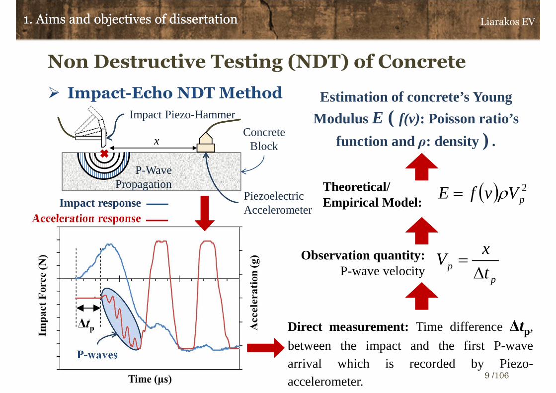
Non Destructive Testing (NDT) of Concrete
� Impact-Echo NDT Method
Direct measurement: Time difference∆tp,
between the impact and the first P-wavearrival which is recorded by Piezo-accelerometer.
pp t
xV
∆=Observation quantity:
P-wave velocity
Theoretical/ Empirical Model:
( ) 2pVvfE ρ=
Estimation of concrete’s Young
Modulus E ( f(v): Poisson ratio’s
function and ρ: density ) .
Piezoelectric Accelerometer
x
Impact Piezo-Hammer
Concrete Block
P-Wave Propagation
Liarakos EV
9 /106
1. Aims and objectives of dissertation1. Aims and objectives of dissertation
Non Destructive Testing (NDT) of Early Age
and Hardened Concrete
� Monitoring of cement’s hydration procedure during the very
early stages of concrete curing (age <48 hours).
� Monitoring of early age concrete hardening and strength
development, the first 28 days after casting.
� In situ control of hardening level in order to be estimated the
suitable time for demolding.
� Detection of changes either in concrete’s stiffness or in elastic
properties, that could be potentially related with the existence
of short or extensive structural damages.
Liarakos EV
10 /106

1. Aims and objectives of dissertation1. Aims and objectives of dissertation
Non Destructive Testing (NDT) of Concrete
and Piezoelectric materials
� Piezoelectric materials exhibit the feature of transforming
mechanical energy to electrical and vice versa.
Implementations in NDT:
• Dynamic motion sensors, Impact Sensors
• High frequency vibration actuators (10-400 kHz)
• Autosensing piezoelectric devices (Both sensing and actuation of
mechanical vibrations)
� Monitoring of structural properties changes by observing the
alteration of piezoelectric materials electrical response.
Liarakos EV
11 /106

1. Aims and objectives of dissertation1. Aims and objectives of dissertation
Dissertation’s Aims
� Development of:
• Analytical models for the mathematical description of electromechanical
interaction between PZTs and concrete constructional elements.
• Analytical methods for the simulation of electrical and mechanical
response of Electro-Mechanical SYStems (EMSYS).
• Reliable set-ups for the safe embedding of PZT based sensors/actuators
inside concrete’s mass.
• Statistical control techniques for the evaluation of structure’s mechanical
integrity.
� Design of an integrated wireless system for the NDT of
concrete structures, based on piezoelectric auto-sensing
devices.
Liarakos EV
12 /106

Dissertation’s Contribution and Novelty
� Regarding to PZT-Concrete electromechanical interaction, in context
of present dissertation an innovative analytical model is proposed.
This model is based in transmission of shear (transverse) waves
in concrete mass and is taking into account both the high stiffness
and the significant mechanical loss factor of concrete [J3].
� Simulation of concrete constructional member’s mechanical
response, by adopting equivalent Multi-Degree Of Freedom (MDOF)
dynamic systems [C2-3,J3].
� Development of an innovative reusable piezoelectric
sensor/actuator, based on a properly designed Teflon (PTFE) casing
which combines adequate mechanical strength and high chemical
resistance [J1-2, C3-5].
1. Aims and objectives of dissertation1. Aims and objectives of dissertation Liarakos EV
13 /106

Dissertation’s Contribution and Novelty
� Development of an integrated system for the measurement of
Electro-Mechanical Impedance (EMI), which employs [J3,C5]:
• Piezoelectric Sensors/Actuators (S/A) embedded in concrete mass. After
embedding, S/A are mechanically behaving like smart aggregates.
• Wireless (Wi-Fi) communication among smart aggregates and EMI’s
measuring equipment.
• Low cost Printed Circuits Boards (PCB) for the record of smart
aggregates electrical response.
• Permanent in-situ installation.
• Recording and classification of EMI measurements in a MySQL designed
database, for remote access in monitoring data.
• Post-Processing of EMI data by connecting MySQL workspace with
MATLAB environment.
1. Aims and objectives of dissertation1. Aims and objectives of dissertation Liarakos EV
14 /106
2.Piezoelectric materials and Electro-
Mechanical SYStems (EMSYS)
Liarakos EV
15 /106

2. Piezoelectric materials and Electro-Mechanical SYStems2. Piezoelectric materials and Electro-Mechanical SYStems
Piezoelectric Materials
� Direct Piezoelectric Effect. The application of an external
mechanical load on a piezoelectric solid results the generation
of an electrical field.
Mechanical energy supplied � Electrical energy stored
� Inverse Piezoelectric Effect. Piezo-materials react to
electric voltage stimulation by appearing mechanical
deformations.
Mechanical energy stored Electrical energy supplied
Liarakos EV
16 /106
Mechanical loading
F
F
V+ -
Electrical charging
V+ -
u u
Direct Inverse
Undeformedpiezo-solid
Deformedpiezo-solid

2. Piezoelectric materials and Electro-Mechanical SYStems2. Piezoelectric materials and Electro-Mechanical SYStems
Piezoelectric Materials: Micro-Structure
� Piezoelectric plane patch PZT (Lead Zirconate Titanate)
� Ceramic Core of Lead and Zirconate/Titanate
Oxide crystal Pb(Zr, Ti)O3
� Metallic Terminals – Dielectric Element
Liarakos EV
17 /106
Metallic Terminalsy3
y1
y2
teQQ ωi33 =
Electric Field : teEE ωi
33 =
Electric Charge
PZT Patch
Polarized PZT Crystal (Ferroelectric Phase T<TC)
TC: Curie Temperature

2. Piezoelectric materials and Electro-Mechanical SYStems2. Piezoelectric materials and Electro-Mechanical SYStems
Piezoelectric Materials: Constitutive equations
� Strain - Charge form equations
� Square PZT patch: Plane Stress(1)
( )
( )
( ) ( )δεεε
ε
i1i1
1
1
33033
333223211313
33211122222
33122121111
−=+=
++=
+−=
+−=
pztEE
E
E
nYY
ETdTdD
EdTvTY
S
EdTvTY
S
yj, j=1:3 : Cartesian Indexes
Sjj: Strain Tensor’s Component
Τjj : Stress Tensor’s Component (Pa)
v12: Poisson ratio(1)
ΥΕ: Young Modulus(1) (Pa)
d31=d32 : Piezoelectric “d” Coefficient(1) (C/N)
D3: Electrical Displacement (C/m²)
E3: Electrical Field (V/m)
ε33: Relative Dielectric Permittivity
npzt : Mechanical Loss Factor
δ: Dielectric Loss Factor
ε0=8.854e-12 (F/m)
(1) Electric and mechanical transverse isotropy along to y1-y2 plane.
Liarakos EV
18 /106

2. Piezoelectric materials and Electro-Mechanical SYStems2. Piezoelectric materials and Electro-Mechanical SYStems
Piezoelectric Materials: Electric Response
� Electric Current, Ι3: Harmonic excitation (V3)
∫==⇒==pztA
dADQIQdt
dQI 3333
33 iii ωωω
( )( )
( ) 312
231
332112
313 1
2
1E
v
YdSS
v
YdD
EE
−−++
−= ε
� Electrical Displacement Amplitude:
Αpzt : Patch
plane area
Harmonic Voltage stimulation (Input)
Electric Current (Output)
h
VE 3
3 = Ground
Liarakos EV
19 /106
2. Piezoelectric materials and Electro-Mechanical SYStems2. Piezoelectric materials and Electro-Mechanical SYStems
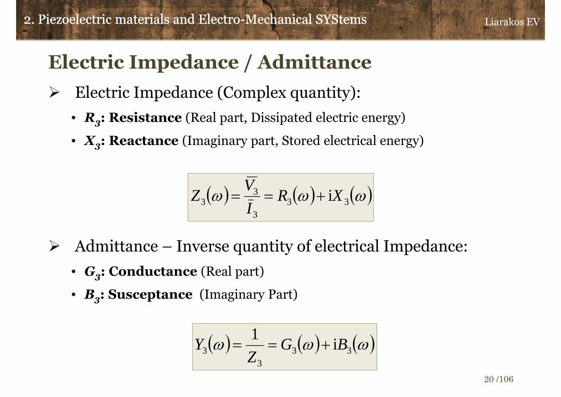
Electric Impedance / Admittance
� Electric Impedance (Complex quantity):
• R3: Resistance (Real part, Dissipated electric energy)
• Χ3: Reactance (Imaginary part, Stored electrical energy)
� Admittance – Inverse quantity of electrical Impedance:
• G3: Conductance (Real part)
• Β3: Susceptance (Imaginary Part)
( ) ( ) ( )ωωω 333
33 iXR
I
VZ +==
( ) ( ) ( )ωωω 333
3 i1
BGZ
Y +==
Liarakos EV
20 /106

Electromechanical response of a PZT patch
� Admittance, Υ3: Harmonic voltage excitation
2. Piezoelectric materials and Electro-Mechanical SYStems2. Piezoelectric materials and Electro-Mechanical SYStems
( )( )
( )
−−=+
−=
12
231
33
2
3312
231
2
3 1
2,
tan
1
2
v
Yd
h
lYY
vh
YdlY
Efixfix
Efree εω
γγ
ω ii EY/ρωκ =
ρ: Density
γ=κl/2
Mechanically free/unloaded PZT (Y3free) Full restriction of PZT’s in-plane
displacements (Y3fix)
Liarakos EV
21 /106
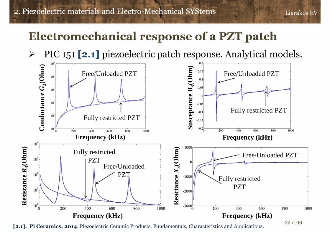
Electromechanical response of a PZT patch
� PIC 151 [2.1] piezoelectric patch response. Analytical models.
2. Piezoelectric materials and Electro-Mechanical SYStems2. Piezoelectric materials and Electro-Mechanical SYStems
[2.1]. Pi Ceramics, 2014. Piezoelectric Ceramic Products. Fundamentals, Characteristics and Applications.
Res
ista
nce R
3(O
hm)
Rea
ctan
ce X
3(O
hm)
Con
duct
ance
G3(
Ohm
)
Sus
cept
ance
B3(
Ohm
)
Free/Unloaded PZT
Fully restricted PZTFully restricted PZT
Free/Unloaded PZT
Free/Unloaded PZT
Fully restricted PZT
Free/Unloaded PZT
Fully restricted PZT
Frequency (kHz) Frequency (kHz)
Frequency (kHz)Frequency (kHz)
Liarakos EV
22 /106

2. Piezoelectric materials and Electro-Mechanical SYStems2. Piezoelectric materials and Electro-Mechanical SYStems
Piezoelectric Materials and NDT
� Direct Piezoelectric Effect. Deformation sensors, stress
sensors, mechanical vibrations detectors.
• Observation quantity: Electric Potential.
� Inverse Piezoelectric Effect. Dynamic motion actuators,
harmonic waves generators.
• Exploited quantity: Deformation due to electrical
stimulation.
� In PZT based NDT techniques, patches are either surficially
attached or embedded in a Structure Under Monitoring
(SUM) and act simultaneously both as actuators and
sensors of dynamic motion (Auto-sensing functionality).
Liarakos EV
23 /106

2. Piezoelectric materials and Electro-Mechanical SYStems2. Piezoelectric materials and Electro-Mechanical SYStems
PZT and Concrete structures mechanical coupling
� From the real structure…
To equivalent physical model
l/2l/2
l/2
l/2 h
y3
y1
y2Electric Voltage
teVV ωi33 =
ZSt
ZSt
SUM’s Mechanical Impedance
ZSt
ZSt
~~
y3
y1
Surficially attached PZT
Concrete Structure Under Monitoring (SUM)Concrete Structure Under Monitoring (SUM)
Concrete structure and PZT
sensor/actuator compose a mechanically
coupled Electro-Mechanical
SYStem (EMSYS).
Liarakos EV
24 /106

2. Piezoelectric materials and Electro-Mechanical SYStems2. Piezoelectric materials and Electro-Mechanical SYStems
PZT and Concrete structures mechanical coupling
� Dynamic Mechanical Impedance-DMI
( )AmplitudeVelocityResponse
AmplitudeForceReaction=ωStZ
( )( )
LAYKL
LK
U
AT
U
FZ E
StStSt
StSt
Ly
Ly
Ly
LySt /,
taniii1
1
1
1
1
11
1
1====
=
=
=
=
κκ
ωωωω
Α: Beam section area
( ) t
U
St eyUu ωκ i111
1
sin43421
=
EStSt Y/ρωκ =
( ) t
T
StStE
St eyUYT ωκκ i1111
11
cos444 3444 21
=
Static Stiffness
Harmonic Wave:Longitudinal beam wave
Tension Compression
Liarakos EV
25 /106
2. Piezoelectric materials and Electro-Mechanical SYStems2. Piezoelectric materials and Electro-Mechanical SYStems
PZT and Concrete structures mechanical coupling
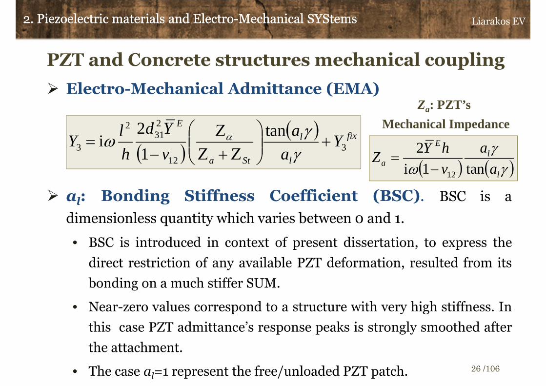
� Electro-Mechanical Admittance (EMΑ)
� al: Bonding Stiffness Coefficient (BSC). BSC is a
dimensionless quantity which varies between 0 and 1.
• BSC is introduced in context of present dissertation, to express the
direct restriction of any available PZT deformation, resulted from its
bonding on a much stiffer SUM.
• Near-zero values correspond to a structure with very high stiffness. In
this case PZT admittance’s response peaks is strongly smoothed after
the attachment.
• The case al=1 represent the free/unloaded PZT patch.
( )( ) fix
l
l
Sta
E
Ya
a
v
Yd
h
lY 3
12
231
2
3
tan
1
2i +
Ζ+ΖΖ
−=
γγ
ω α
Za: PZT’s
Mechanical Impedance
( ) ( )γγ
ω l
lE
a a
a
v
hYZ
tan1i
2
12−=
Liarakos EV
26 /106

PZT and Concrete structures mechanical coupling
� Electro-Mechanical Admittance (EMΑ) and concrete
structures
Concrete’s constructional elements,
usually exhibit much higher stiffness than
PZT patches.
αl→0
tan(αlγ)/αlγ→1
2. Piezoelectric materials and Electro-Mechanical SYStems2. Piezoelectric materials and Electro-Mechanical SYStems
( ) ( )123
12
231
2
3 1i
2,
1
2i
v
hYZY
v
Yd
h
lY
E
afix
Sta
E
−=+
+−=
ωΖΖ
Ζω α
Liarakos EV
27 /106
Concrete structural element
Surficiallyattached PZT
Shear waves
propagation
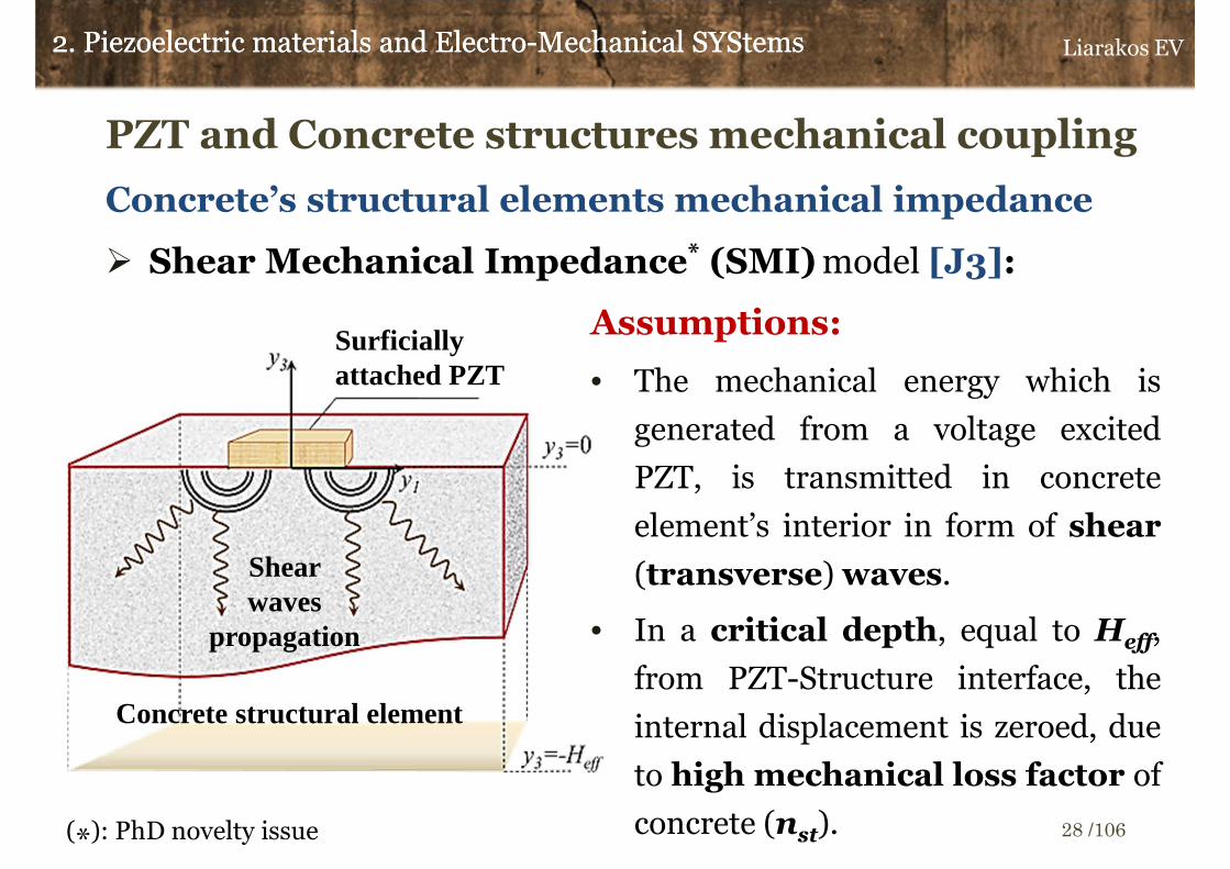
PZT and Concrete structures mechanical coupling
Concrete’s structural elements mechanical impedance
� Shear Mechanical Impedance* (SMI) model [J3]:
2. Piezoelectric materials and Electro-Mechanical SYStems2. Piezoelectric materials and Electro-Mechanical SYStems
Assumptions:
• The mechanical energy which is
generated from a voltage excited
PZT, is transmitted in concrete
element’s interior in form of shear
(transverse) waves.
• In a critical depth, equal to Ηeff,
from PZT-Structure interface, the
internal displacement is zeroed, due
to high mechanical loss factor of
concrete (nst).
Liarakos EV
28 /106(*): PhD novelty issue
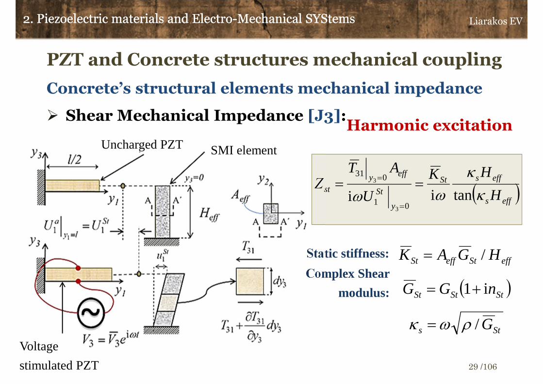
PZT and Concrete structures mechanical coupling
Concrete’s structural elements mechanical impedance
� Shear Mechanical Impedance [J3]: Harmonic excitation
2. Piezoelectric materials and Electro-Mechanical SYStems2. Piezoelectric materials and Electro-Mechanical SYStems
( )
Sts
StStSt
effSteffSt
G
nGG
HGAK
/
i1
/
ρωκ =
+=
=
( )effs
effsSt
y
St
effyst H
HK
U
ATZ
κ
κ
ωω tanii01
031
3
3 ===
=
Complex Shear
modulus:
Static stiffness:
Uncharged PZT SMI element
Voltage
stimulated PZT
Liarakos EV
29 /106

PZT and Concrete structures mechanical coupling
Concrete’s structural elements mechanical impedance
� Shear Mechanical Impedance (SMI):
• The proposed analytical model is approaching the mechanical response of
concrete structural elements by defining an equivalent Single Degree Of
Freedom (SDOF) and continuous shear element.
• SMI’s mathematical expression is approving the strong physical correlation
among the mechanical response of a structure, the geometric features
of constructional elements (Ηeff) and the mechanical properties of
building materials (nSt, GSt).
• Expanding SMI model’s philosophy, in context of present dissertation, a
novelty method of structural impedance simulation is developed
based on Multi-Degree Of Freedom (MDOF) dynamic systems which are
consisted of a specific number of SMI components in parallel set-up.
2. Piezoelectric materials and Electro-Mechanical SYStems2. Piezoelectric materials and Electro-Mechanical SYStems Liarakos EV
30 /106
3.Electro-Mechanical Impedance
method (EMI)
Liarakos EV
31 /106

Fundamental implementation issues
� EMI method is one the most widespread techniques regarding to
PZT based non-destructive evaluation of engineering structures
[J1].
� PZT patches are surficially bonded [C2] or embedded [J1-3, C1]
to concrete constructional members and via a time-depended
voltage excitation force SUMs to vibration mode.
� EMI method’s main observation tool is the electrical impedance
response spectrum (frequency domain analysis) Z3(ω), which is
obtained from bonded/embedded PZTs electrical response.
� In cases of engineering structures monitoring, EMI spectra
frequency range varies from 10 to 400 kHz [J1].
3. Electro-Mechanical Impedance method (EMI)3. Electro-Mechanical Impedance method (EMI) Liarakos EV
32 /106

Fundamental implementation issues
� EMI method’s applications usually are exploiting PZT patches
both as mechanical vibration actuators (Inverse Piezo-Effect) and
as dynamic motion response sensors (Direct Piezo-effect).
� EMI’s spectra of bonded PZTs can be termed as the
electromechanical signatures of a SUM.
� EMI signatures are unique for each structure and reflecting their
specific dynamic features.
3. Electro-Mechanical Impedance method (EMI)3. Electro-Mechanical Impedance method (EMI)
Concrete SUM
Response
mechanical stress
Mechanical strain PZT
Response
electrical current,
I3 (Output)
Excitation Electric
voltage, V3 (Input)
Integrated RLC -Meter
Direct Direct
InverseInverse
Liarakos EV
33 /106

Fundamental implementation issues
Each irregular change in SUM’s structural properties that has emerged
either from a damage existence or from an alteration in material's
mechanical properties, will affect directly the shape of EMI’s signatures.
3. Electro-Mechanical Impedance method (EMI)3. Electro-Mechanical Impedance method (EMI)
Crack
PZT
In-Plane Symmetry
Boundary Conditions
Undamaged
SUM
Mechanical
Damage Case
Res
ista
nce
R3 (O
hm
)
Frequency (kHz)
Numerical Simulation of a concrete
beam (SUM) which is hosting a
surficial bonded PZT. Analysis in
Frequency Domain. Displacements
field color map: 60 kHz. [C2].
Liarakos EV
34 /106

Measuring EMI: Set-ups, Equipment
� Integrated multifunctional RLC-Meters (Impedance Analyzers)
• High accuracy and broad range of sweeping frequencies (1kHz-
5MHz).
• Significant cost | Drawback regarding to permanent installation
• Restricted portability | Drawback regarding to structure’s in-situ
control
� Simple and custom electronic set-up for EMI measuring
• Efficient measuring of EMI in narrow frequencies range
• Low cost measuring circuits based on resistors/capacitors
components
• Low cost Printed Circuits Boards (PCB) which are based on
integrated impedance converters
3. Electro-Mechanical Impedance method (EMI)3. Electro-Mechanical Impedance method (EMI) Liarakos EV
35 /106

Measuring EMI: Principles
3. Electro-Mechanical Impedance method (EMI)3. Electro-Mechanical Impedance method (EMI)
out
outinmeas
out
p
FV
FVFVR
I
VZ
−==3
~~→
( )tVinmeas
outout R
VI =
Electric Resistors measuring set-up, Rmeas
PZT
( )tVp( )tVout
Output Current
Vin and Vout data acquisition in time domain applying a sample rate equal
to Fs=1/dt.
Fourier spectra calculation: FVin
and FVout
Discrete Fourier Transform (DFT)
Liarakos EV
36 /106
Measuring EMI: Excitation voltage functions Vin
� Sweeping frequency range: [freqstart, freqend]
� Single-Harmonic Functions. Discrete single-sine signals of
determinate excitation frequency and duration.
� Multi-Harmonic Functions. Continuous excitation for a
specific time window (tsweep).
• Multi-Sine Functions. Sum of single-sine functions of
scalar increasing frequencies which are varying between an
initial and a final scanning frequency (freqstart and freqend
respectively).
• Chirp Signals. Trigonometric functions of time-
dependent excitation frequency.
3. Electro-Mechanical Impedance method (EMI)3. Electro-Mechanical Impedance method (EMI) Liarakos EV
37 /106

Measuring EMI: Wiring PZT’s terminals
� Free/Unloaded PZT patch. Type: PIC 151.
� Thermal soldering of electrodes on PZT’s terminals using a
Tin(Sn)-based alloy.
� Soldering temperature must not overcomes the Curie
temperature.
3. Electro-Mechanical Impedance method (EMI)3. Electro-Mechanical Impedance method (EMI)
Upper PZT’s terminal
Soldered electrodes
PIC 151 type PZT
Folding of bottom PZT’sterminal on upper face
Liarakos EV
38 /106

Measuring EMI: Multifunctional integrated
RLC-meter
� Free/Unloaded PZT patch. Type: PIC 151.
� Sweeping frequencies range 10-1000 kHz, 5 Different PZTs.
3. Electro-Mechanical Impedance method (EMI)3. Electro-Mechanical Impedance method (EMI)
Rea
ctan
ce X
3(O
hm)
Free PZT’s signature before
electrodes soldering
Res
ista
nce R
3(O
hm)
Frequency (kHz) Frequency (kHz)
Liarakos EV
39 /106

Measuring EMI: Multifunctional integrated
RLC-meter
� EMI signature of a PZT, bonded on a concrete cubic specimen (Edge
length 150 mm).
3. Electro-Mechanical Impedance method (EMI)3. Electro-Mechanical Impedance method (EMI)
Free/Unloaded
PZT
Surficially attached PZT on a
concrete cube
Peaks related to concrete response
(30-150 kHz)
Res
ista
nce R
3(O
hm)
Frequency (kHz)
Liarakos EV
40 /106
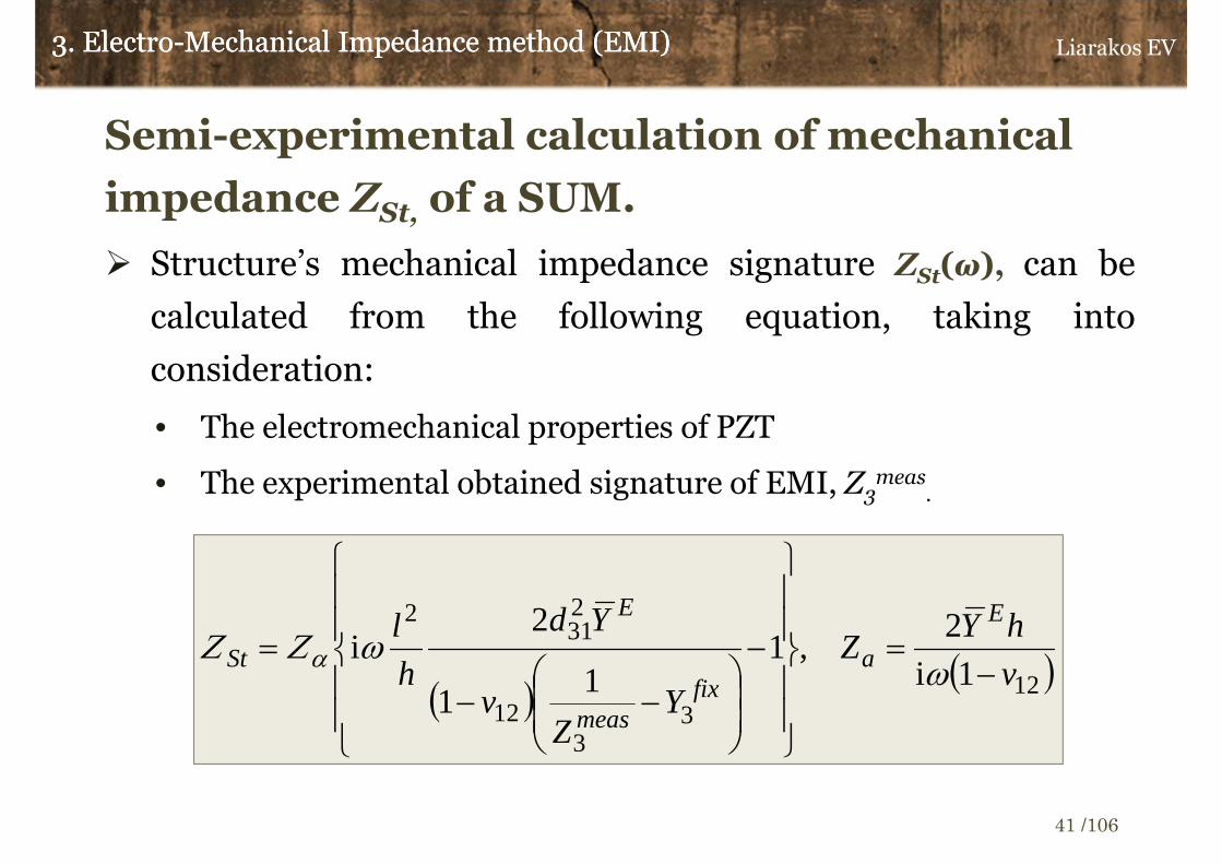
Semi-experimental calculation of mechanical
impedance ZSt, of a SUM.
� Structure’s mechanical impedance signature ZSt(ω), can be
calculated from the following equation, taking into
consideration:
• The electromechanical properties of PZT
• The experimental obtained signature of EMI, Ζ3meas
.
3. Electro-Mechanical Impedance method (EMI)3. Electro-Mechanical Impedance method (EMI)
( )( )12
33
12
231
2
1i
2,1
11
2i
v
hYZ
YZ
v
Yd
h
l E
afix
meas
E
St −=
−
−−
=ω
ωΖΖ α
Liarakos EV
41 /106

3. Electro-Mechanical Impedance method (EMI)3. Electro-Mechanical Impedance method (EMI)
Semi-experimental calculation of mechanical
impedance ZSt, of a SUM.
Mechanical impedance signatures ZSt(ω), in several monitoring
cases uncovers and amplifies additional information regarding
to SUM’s dynamic features.
Liarakos EV
42 /106
Mechanical resonant frequencies
Frequency (kHz)
Mec
hani
cal I
mpe
danc
ere
al p
art
RSt
(Ns/
m)
Mea
sure
d R
esis
tanc
e
R3
mea
s(O
hm)

4.Structural integrity assessment of
concrete structures
Liarakos EV
43 /106
Comparative analysis of EMI signatures
Evaluation of structures integrity via Electro-Mechanical
Impedance (EMI) method:
� Based on the acquisition and interpretation of electrical (Z3) or
mechanical (ZSt) impedance signatures (frequency domain),
and especially on their real parts R3 and RSt [J2].
� It is a procedure of comparative analysis among a Reference
Signature (RS) that represent the response of undamaged
(healthy) structure and every other signature which is referred
to current (Current Signature - CS) integrity condition of
the structure.
4. Structural integrity assessment of concrete structures4. Structural integrity assessment of concrete structures Liarakos EV
44 /106

Comparative analysis of EMI signatures
Reference Signatures (RS) are expressing:
• In proceedings of structural health monitoring, the dynamic
response of undamaged structures.
• In proceedings of early age concrete hardening monitoring, the
dynamic response of a structure with specific mechanical
characteristics, which is taken arbitrary as reference state.
RS is determined,
• Experimentally. Measuring of electrical response.
Response spectrum RSmeas: F measuring points (ωi, Z3,imeas), i=1:F.
• Approximately. Simulation of EMSYS electrical response.
Z3,imeas≈Z3
est (ωi, p), i=1:F, p: Model’s parameters vector.
4. Structural integrity assessment of concrete structures4. Structural integrity assessment of concrete structures Liarakos EV
45 /106

Statistical Damage indexes
� Statistical quantities based on cumulative variance between the
reference signature (RS) and every current signature (CS).
� Root Mean Square Deviation - RMSD
4. Structural integrity assessment of concrete structures4. Structural integrity assessment of concrete structures
( )( )
∑
∑
=
=
−×=
F
ii
F
iii
RS
RSCSRMSD
1
2
1
2
100%
i=1:F, F : Length of signatures vector.
RSi and CSi, i-th value of each spectrum. Corresponding to angular frequency ωi.
( )minmaxmin 1
1ωωωω −
−−
+=F
ii
Continuous range of angular frequencies.
Liarakos EV
46 /106

Statistical Damage indices
Advantages
� Widespread application in EMI based non-destructive evaluation
procedures
� Low mathematical complexity
� High level of reliability in cases of early age concrete monitoring
procedures [J2]
Disadvantages
� Limited detection ability of signatures changes which are located in
short parts of scanning frequency range and reflect serious damages.
� No confidence limits determination for the acceptable changes among
consecutive measurements of reference state’s signatures.
4. Structural integrity assessment of concrete structures4. Structural integrity assessment of concrete structures Liarakos EV
47 /106

Statistical Control
Aim: Avoid errors in the evaluation of concrete structural
integrity.
• Type Ι error: False detection of a mechanical damage that does
not exists (Wrong alarm).
• Type IΙ error: Fail of detection of an existing mechanical
damage (Damage diagnosis failure).
� Definition of a magnitude which expresses the range of signatures
alteration and it is based on the simulation of undamaged structure's
response in frequency domain.
� Determination of confidence limits regarding to the acceptable
changes among EMI’s signatures that correspond to undamaged
structure.
4. Structural integrity assessment of concrete structures4. Structural integrity assessment of concrete structures Liarakos EV
48 /106

Statistical Control: Methodology
� Simulation of measured reference signatures RSmeas, via an
estimation mathematical model, RSest.
• Non linear regression of RSmeas. Rational polynomials of angular
frequency ω, with complex parameters.
• Mathematical models that derived from the approximation of real
structure with equivalent semi-discrete dynamic systems.
� Calculation of residuals r (signatures changes
magnitude), between estimated reference signature RSest and
each measured current state signature CSmeas.
4. Structural integrity assessment of concrete structures4. Structural integrity assessment of concrete structures
estmeas RSCSr −=
Liarakos EV
49 /106
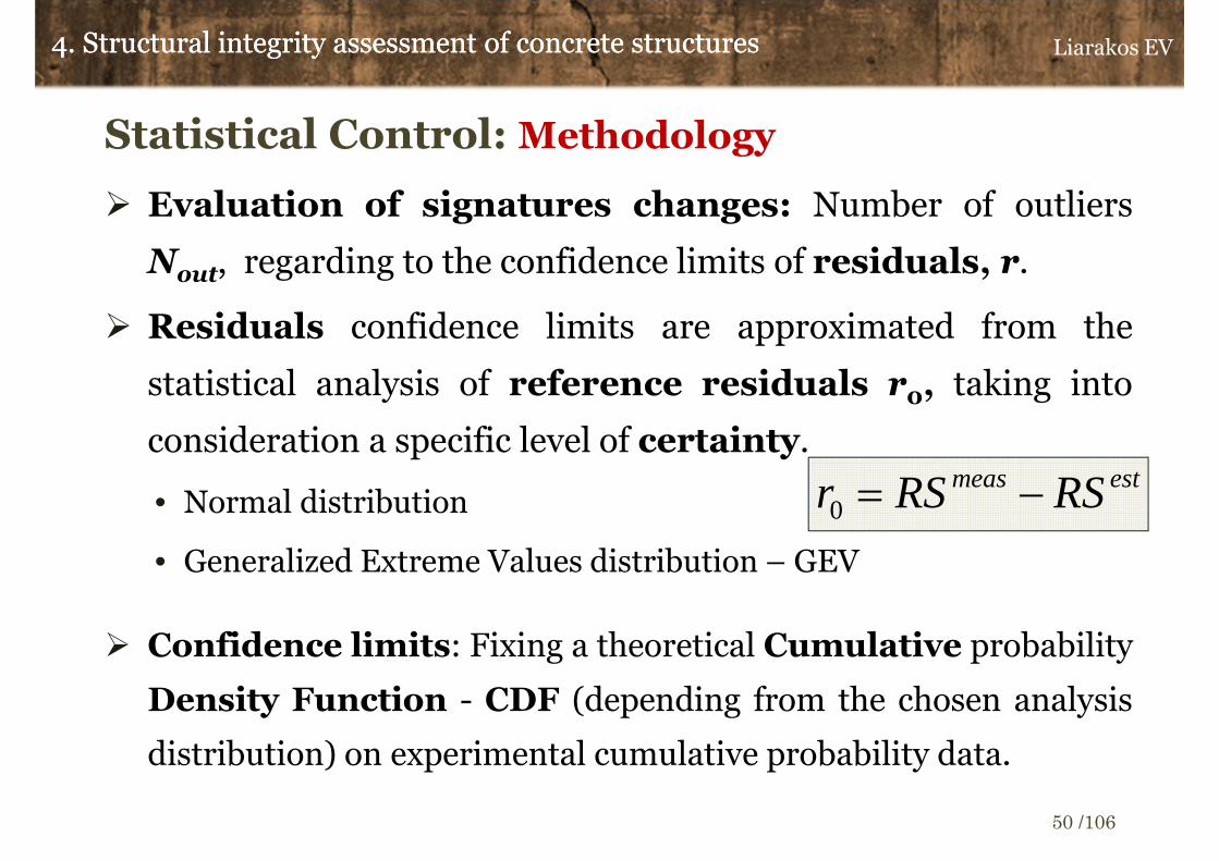
Statistical Control: Methodology
� Evaluation of signatures changes: Number of outliers
Νout, regarding to the confidence limits of residuals, r.
� Residuals confidence limits are approximated from the
statistical analysis of reference residuals r0, taking into
consideration a specific level of certainty.
• Normal distribution
• Generalized Extreme Values distribution – GEV
� Confidence limits: Fixing a theoretical Cumulative probability
Density Function - CDF (depending from the chosen analysis
distribution) on experimental cumulative probability data.
4. Structural integrity assessment of concrete structures4. Structural integrity assessment of concrete structures
estmeas RSRSr −=0
Liarakos EV
50 /106

Statistical Control: Confidence limits
Acceptable number of outliers:
Certainty level (%) = (Pup-Plow) x 100
4. Structural integrity assessment of concrete structures4. Structural integrity assessment of concrete structures
( ){ } 10010 ×−−×= lowupout PPFN
(ωi, RSimeas), i=1:F
F: Length of RS vector
Reference residuals r0
CD
F
Experimental CDF
Theoretical CDF
Lower confidence
limit, Lr0
Upper Confidence
Limit , Ur0
( )
( )up
low
PCDFUr
PCDFLr
10
10
−
−
=
=
Plow
Pup
Av
er
ag
e v
alu
e
Liarakos EV
51 /106

Statistical control of outliers: Signatures
evaluation
Changes in structural integrity or in mechanical properties of
concrete.
4. Structural integrity assessment of concrete structures4. Structural integrity assessment of concrete structures
0outout NN >
Certainty: 99%
Plow=0.005 ή 0.5 %
Pup=0.995 ή 99.5 %
Νout0= 1
Nout=68
F=105
E[r]: Residuals
AverageUndamaged structure’s signature
Damaged structure’s
signature
rd=
r-E
[r]
Lower confidence
limit, Lr0
Upper Confidence
Limit, Ur0
Frequency (kHz)
Liarakos EV
52 /106

Statistical control of outliers: Functional Diagram
4. Structural integrity assessment of concrete structures4. Structural integrity assessment of concrete structures
Experimental measurement RSmeas Experimental measurement CSmeas
Simulation ofRSmeas via RSest model
Calculation of reference residuals
r0=RSmeas- RSest
Zeroing of reference residuals average
value (detrending): r0d=r0-E[r0]
Calculation of r0d confidence limits,
Lr0d =CDF-1(Pout) and
Ur0d =CDF-1(Pup).
CSmeas Residuals Calculation:
r=CSmeas- RSest
Zeroing of CSmeas residuals average value
(detrending): rd=r-E[r]
Statistical control of rd , based on Lr0d
and Ur0d confidence limits
Outliers: Νout
Residuals out of
statistical control.
Detection of
signature’s frequency
range parts, where
outliers are
concentrated. Evaluation of structural
integrityEvaluation of structural
integrity
Liarakos EV
53 /106

Simulation of undamaged structure reference
signature: Electro-Mechanical Impedance (EMI), Ζ3.
Measured EMI signature Ζ3meas, can be simulated from a rational
polynomial function of angular frequency, Ζ3est(ω,p) [J3].
4. Structural integrity assessment of concrete structures4. Structural integrity assessment of concrete structures
( ) FirZXRZ iiestmeas
imeas
imeas
i :1,i 3,3,3,3 =+=+= pω
( )[ ]Tnodo
donobbbaaa LL 1010
12=
×++p
( ) ( )( ) ∑
∑+
=
−−
+
=
−−
== 1
1
11
1
1
11
3 ,
,,
do
q
qiq
no
p
pip
i
ii
est
a
b
D
NZ
ω
ω
ωω
ωab
p
Liarakos EV
54 /106

Simulation of undamaged structure reference
signature: Electro-Mechanical Impedance (EMI), Ζ3.
p-vector’s optimum values are identified via minimization of
sum of squared differences (residuals) between experimentally
measured and model-calculated signatures (Least Squares
Method - LSM).
Present problem is classified in family of non-linear least squares
problems and could be resolved via lsqnonlin MATLAB function
(MATLAB | Optimization toolbox).
4. Structural integrity assessment of concrete structures4. Structural integrity assessment of concrete structures
( ){ } ∑∑==
=−F
ii
F
ii
estmeasi rZZ
1
2
1
2
3,3 min,minpp
pω
Liarakos EV
55 /106
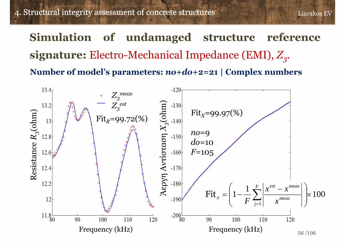
Simulation of undamaged structure reference
signature: Electro-Mechanical Impedance (EMI), Ζ3.
4. Structural integrity assessment of concrete structures4. Structural integrity assessment of concrete structures
Number of model’s parameters: no+do+2=21 | Complex numbers
no=9do=10F=105
FitX=99.97(%)FitR=99.72(%)
1001
11
×
−−= ∑
=
F
jmeas
measest
x
xx
FxFit
Res
ista
nce
R3(o
hm
)
Άερ
γη
Αν
τίσ
τασ
η Χ
3(o
hm
)
Ζ3meas
Ζ3est
Frequency (kHz) Frequency (kHz)
Liarakos EV
56 /106
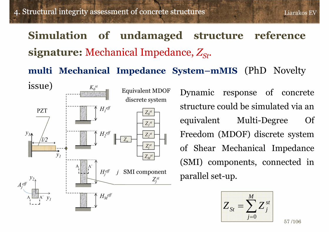
Simulation of undamaged structure reference
signature: Mechanical Impedance, ΖSt.
multi Mechanical Impedance System–mMIS (PhD Novelty
issue)
4. Structural integrity assessment of concrete structures4. Structural integrity assessment of concrete structures
Dynamic response of concrete
structure could be simulated via an
equivalent Multi-Degree Of
Freedom (MDOF) discrete system
of Shear Mechanical Impedance
(SMI) components, connected in
parallel set-up.
∑=
=M
j
stjSt ZZ
0
Equivalent MDOF
discrete system
SMI component
Liarakos EV
57 /106

Simulation of undamaged structure reference
signature: Mechanical Impedance, ΖSt.
Frequency response function of equivalent system.
Experimental signatures of mechanical impedance ΖStmeas, are
calculated from the measured electrical impedance signature
Ζ3meas .
4. Structural integrity assessment of concrete structures4. Structural integrity assessment of concrete structures
( )( )∑∑
==
+=+=M
jeffjjs
jStjseffj
stM
j
stj
stSt
H
GAKZZZ
1 ,
,,0
10
tani
1
i,
κ
κ
ωωω p
( )
St
Steffj
j
jStStjs
stjStjSt
G
Hfreq
G
nGG
ρ
ρωκ
2
1
/
i1
0
,,
,
=
=
+=
( )Fj
YZ
v
Yd
h
l
fixmeas
i
E
iimeas
iSt :1,11
1
2i
3,3
12
231
2
,, =
−
−−
Ζ=Ζ ωα
[ ]stM
steffM
effeffM
effst nnHHAAK LLL 1110=p
Liarakos EV
58 /106

Simulation of undamaged structure reference
signature: Mechanical Impedance, ΖSt.
p-vector’s optimum values are approximated via minimization
of sum of squared differences between experimentally measured
and model-calculated, signatures. (Non-linear least squares with
constraints, lsqnonlin | MATLAB – Optimization Toolbox)
4. Structural integrity assessment of concrete structures4. Structural integrity assessment of concrete structures
{ } ( ){ }[ ]
1
0tosubject
,ReRemin1
2
,
<
>
−∑=
stj
F
ii
estSt
measiSt
n
ZZ
p
pp
ω
[ ]stM
steffM
effeffM
effst nnHHAAK LLL 1110=p
Liarakos EV
59 /106

Simulation of undamaged structure reference
signature: Mechanical Impedance, ΖSt.
4. Structural integrity assessment of concrete structures4. Structural integrity assessment of concrete structures
freq0,j
(kHz)Heff,j
(mm) Aeff,j
(mm2)nst,j
3.32 343.24 2.20E-03 0.01
9.78 116.65 1.49E+00 0.17
85.67 13.32 6.73E-02 0.14
94.23 12.11 3.03E-02 0.07
112.22 10.17 9.55E-02 0.14
mMIS model’s parameters: 15
( )
St
Steffj
j
jStStjs
stjStjSt
G
Hfreq
G
nGG
ρ
ρωκ
2
1
/
i1
0
,,
,
=
=
+=
Frequency (kHz)
Liarakos EV
60 /106

Simulation of undamaged structure reference
signature: Mechanical Impedance, ΖSt.
Advantages of mMIS model in comparison to non-linear
polynomial regression
� Significantly fewer modelling parameters.
� Modelling parameters are representing mechanical quantities which are
strongly correlated with the dynamic features of the structure.
� Calculation of structure’s resonant frequencies.
� Estimation of structure’s dynamic response and resonant frequencies at
frequency points out of experimentally swept range.
Restrictions regarding to concrete structures monitoring
mMIS parameters have physical interpretation only if concrete constructional
elements have adequate stiffness (at least 24 hours after concrete fabrication).
4. Structural integrity assessment of concrete structures4. Structural integrity assessment of concrete structures Liarakos EV
61 /106

5.Integrated wireless system for
automatic EMI measurement
Liarakos EV
62 /106

In context of present dissertation (PhD Novelty issue) is developed an
integrated monitoring system termed as T-WiEYE (Teflon-based
Wireless intergratEd monitoring SYstEm), combining [J3]:
� Piezoelectric patches as sensors/actuators.
• PZT – PIC 151 (PI Ceramics Inc.)
• SMart Agreggates-SMA. Embedding of PZT patches in concrete
mass simultaneously with the casting of constructional elements.
• Teflon casing of PZT patches. PZT protection from early age
concrete moisture, concrete condensation vibration and concrete
shrinkage deformation.
� Wi-Fi contact between SMAs and data acquisition/storage
system.
5. Integrated wireless system for automatic EMI measurement5. Integrated wireless system for automatic EMI measurement Liarakos EV
63 /106

In context of present dissertation (PhD Novelty issue) is developed an
integrated monitoring system termed as T-WiEYE (Teflon-based
Wireless intergratEd monitoring SYstEm), combining [J3]:
� AD5933 (Analog Devices). Low cost integrated circuit for the
measurement of EMI in frequency domain.
� Ability of permanent installation in structure’s space, for continuous
evaluation of structural integrity.
� Integrated access and overview of measured EMI data.
• EMI data registration in a MySQL developed database.
• Access to MySQL database through MATLAB workspace.
• Remote mining and overview of EMI data for post-processing and
signature’s evaluation (Statistical control of signatures).
5. Integrated wireless system for automatic EMI measurement5. Integrated wireless system for automatic EMI measurement Liarakos EV
64 /106

T-WiEYE System
Functionality diagram [J3]
CliC: Client Computer
SerCo: Server Computer
UC: User Computer
Concrete– SMA
AD5933 EB EMI signature acquisition
Vin
Vout USB Connection
Wi-Fi Client Hub
Wi-Fi transmission of EMI data
Wi-Fi Server Hub
AD5933 Administration software
Java interface for EMI data send to SerCo
Temporally storage of EMI data
CliC
Data registration to EMI database (MySQL)
SerCo
Overview/Mining of data viaMySQL-MATLAB interface
UC
Lan
/Inte
rnet
Lan
/Inte
rnet
5. Integrated wireless system for automatic EMI measurement5. Integrated wireless system for automatic EMI measurement
USB Connection
Liarakos EV
65 /106

T-WiEYE System
Functionality diagram
� CliC: Client Computer.
• Control and administration EMI measurement system (AD5933).
• Set-up in structure’s space, inside to Wi-Fi covering area.
• Connection with SerCo via internet or LAN.
CliC: Client Computer
SerCo: Server Computer
UC: User Computer
5. Integrated wireless system for automatic EMI measurement5. Integrated wireless system for automatic EMI measurement
AD5933 Administration software
Java interface for EMI data send to SerCo.
Temporally storage of EMI data
CliCData registration to EMI database (MySQL)
SerCo
Lan
/Inte
rnet
Lan
/Inte
rnet
Overview/Mining of data viaMySQL-MATLAB interface
UC
Liarakos EV
66 /106

T-WiEYE System
Functionality diagram
� Remote MySQL workspace administration via MATLAB environment
� Development of a MATLAB scripted, GUI application
5. Integrated wireless system for automatic EMI measurement5. Integrated wireless system for automatic EMI measurement
UC|Remote user
Liarakos EV
67 /106
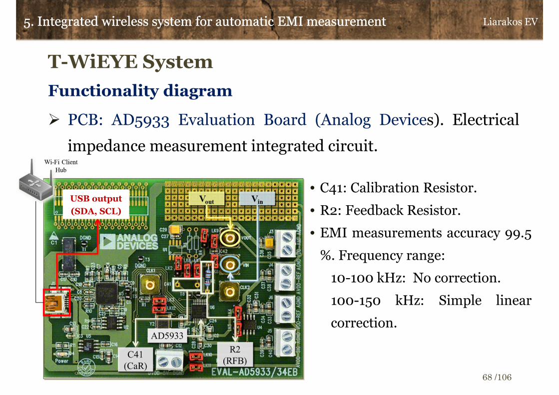
USB output
(SDA, SCL)
T-WiEYE System
Functionality diagram
� PCB: AD5933 Evaluation Board (Analog Devices). Electrical
impedance measurement integrated circuit.
• C41: Calibration Resistor.
• R2: Feedback Resistor.
• EMI measurements accuracy 99.5
%. Frequency range:
10-100 kHz: No correction.
100-150 kHz: Simple linear
correction.
5. Integrated wireless system for automatic EMI measurement5. Integrated wireless system for automatic EMI measurement Liarakos EV
68 /106
T-WiEYE System
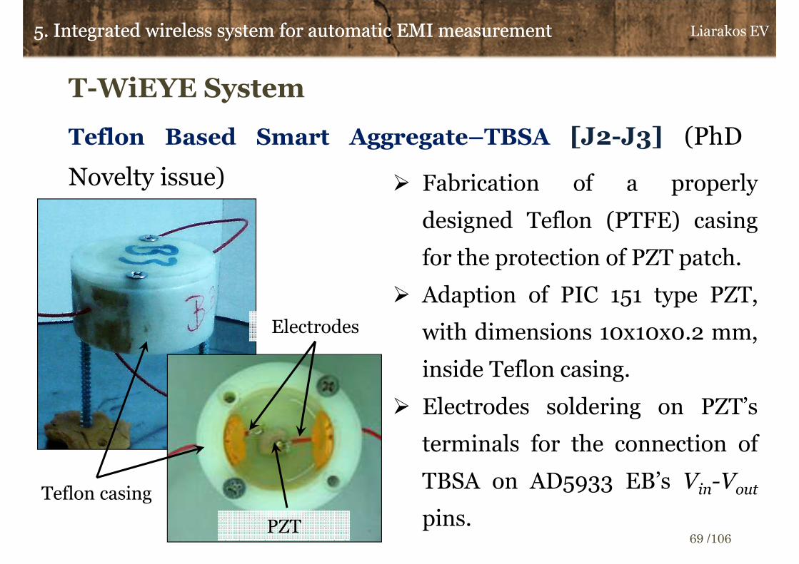
Teflon Based Smart Aggregate–TBSA [J2-J3] (PhD
Novelty issue)
Teflon casing
PZT
Electrodes
� Fabrication of a properly
designed Teflon (PTFE) casing
for the protection of PZT patch.
� Adaption of PIC 151 type PZT,
with dimensions 10x10x0.2 mm,
inside Teflon casing.
� Electrodes soldering on PZT’s
terminals for the connection of
TBSA on AD5933 EB’s Vin-Vout
pins.
5. Integrated wireless system for automatic EMI measurement5. Integrated wireless system for automatic EMI measurement Liarakos EV
69 /106

T-WiEYE System
Teflon Based Smart Aggregate –TBSA [J2-J3] (PhD
Novelty issue)� Fixing of steel bolt on Teflon casing for
robust anchoring of TBSA in concrete
mass.
� Anchoring is improving the mechanical
conductivity between TBSA and
concrete’s mass.
� Mechanical conductivity. The ability
of an interface between different
materials to allow the transmission of
mechanical energy, via waves, with the
fewer possible losses.
TBSA’s steel anchoring bolt
5. Integrated wireless system for automatic EMI measurement5. Integrated wireless system for automatic EMI measurement Liarakos EV
70 /106

T-WiEYE System
Teflon Based Smart Aggregate –TBSA
Resume of innovative elements:
� Teflon casing. Adequate mechanical strength and chemical
resistance regarding to chemically active components of
concrete (cement and water).
� Anchoring in concrete mass
� Accessibility to sensing/actuating core of TBSA for possible
repairing of PZT’s electrodes.
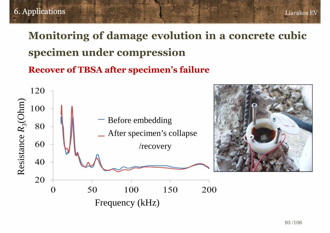
� Ability of TBSA recovering after the ending of a monitoring
session and reusability option.
5. Integrated wireless system for automatic EMI measurement5. Integrated wireless system for automatic EMI measurement Liarakos EV
71 /106

6.Applications
Liarakos EV
72 /106
Laboratory scale concrete structural elements
� Monitoring of physical processes.
• Hydration of very early age concrete. Until 48 hours after
fabrication.
• Development of stiffness and hardening evolution of early
age concrete. Until 28 days after fabrication.
� Monitoring of damages (cracks) start and propagation, in
concrete elements.
• Cubic specimens under compression loading
• Beam specimens under bending
6. Applications6. Applications Liarakos EV
73 /106

Mechanical properties of concrete
� Laboratorial concrete (No chemical admixtures)
� C20/25. Composition (kg/m³):
• Gravel | Coarse aggregates (dg>25mm): 850
• Middle size aggregates (2.5 mm< dg < 9.5mm): 450
• Sand | Fine aggregates (dg <2.5mm): 550
• Cement, CEM II/A-M 42.5 N: 310
• W/C = 0.65 (Water to Cement ratio)
� Theoretical density : 2360 kg/m³
� Theoretical weight of cubic specimen : 7.95 kg
6. Applications6. Applications
dg: Grind size/ Sieve mesh opening
Cubic specimen’s edge length: 150mm
Liarakos EV
74 /106
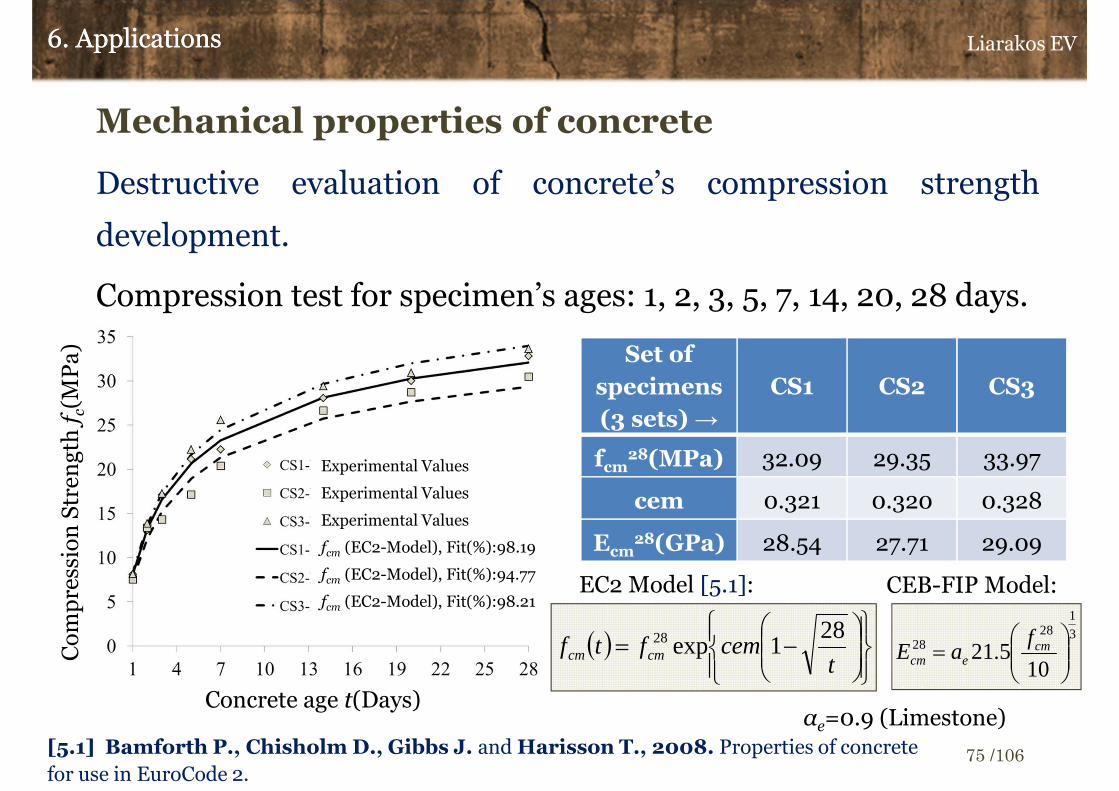
Mechanical properties of concrete
Destructive evaluation of concrete’s compression strength
development.
Compression test for specimen’s ages: 1, 2, 3, 5, 7, 14, 20, 28 days.
6. Applications6. Applications
Set of
specimens
(3 sets) →
CS1 CS2 CS3
fcm28(MPa) 32.09 29.35 33.97
cem 0.321 0.320 0.328
Ecm28(GPa) 28.54 27.71 29.09
3
128
28
105.21
= cm
ecm
faE
CEB-FIP Model:
αe=0.9 (Limestone)[5.1] Bamforth P., Chisholm D., Gibbs J. and Harisson T., 2008. Properties of concrete
for use in EuroCode 2.
Concrete age t(Days)
Co
mp
ress
ion
Str
eng
th f
c(M
Pa
)
Experimental Values
Experimental Values
Experimental Values
fcm (EC2-Model), Fit(%):98.19
fcm (EC2-Model), Fit(%):94.77
fcm (EC2-Model), Fit(%):98.21
( )
−=
tcemftf cmcm
281exp28
ΕC2 Model [5.1]:
Liarakos EV
75 /106

EMI based monitoring of early age concrete
� 5 concrete cubic specimens. 3 of them are fabricated from the same
casting portion (C1-3) and the other 2 from different casting portions
(C4, C5).
6. Applications6. Applications
TBSA / SMA
Concrete Specimen
Liarakos EV
76 /106

EMI based monitoring of early age concrete
� T-WiEYE System.
• Recording signature: EMI real part, R3 (Resistance).
• Frequency range: 50-100 kHz
• Continuous recording of R3 signatures, starting 3 after concrete casting.
• Signatures recording rate: 1 signature per hour for the first 192
hours (8 days) and 1 signature per day from 9 to 28 days.
� Evaluation of R3 signatures changes
• Reference signature: The R3,signature which is corresponding to 3
hour age concrete (semi-liquid phase)
• Evaluation of signatures changes via RMSD
• Investigation of RMSD changes relatively to concrete age
6. Applications6. Applications Liarakos EV
77 /106
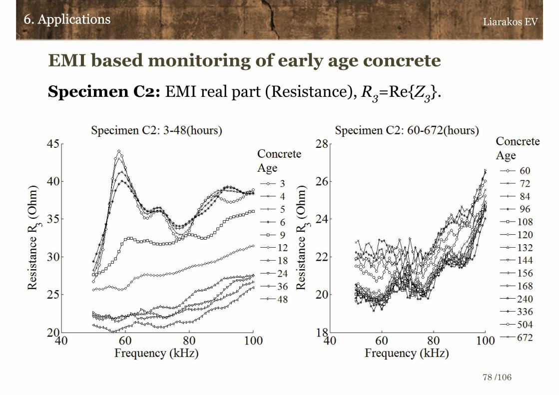
EMI based monitoring of early age concrete
Specimen C2: EMI real part (Resistance), R3=Re{Z3}.
6. Applications6. Applications Liarakos EV
78 /106

EMI based monitoring of early age concrete
Specimen C4: EMI real part (Resistance), R3=Re{Z3}.
6. Applications6. Applications Liarakos EV
79 /106

EMI based monitoring of early age concrete
Specimen C5: EMI real part (Resistance), R3=Re{Z3}.
6. Applications6. Applications Liarakos EV
80 /106
EMI based monitoring of early age concrete
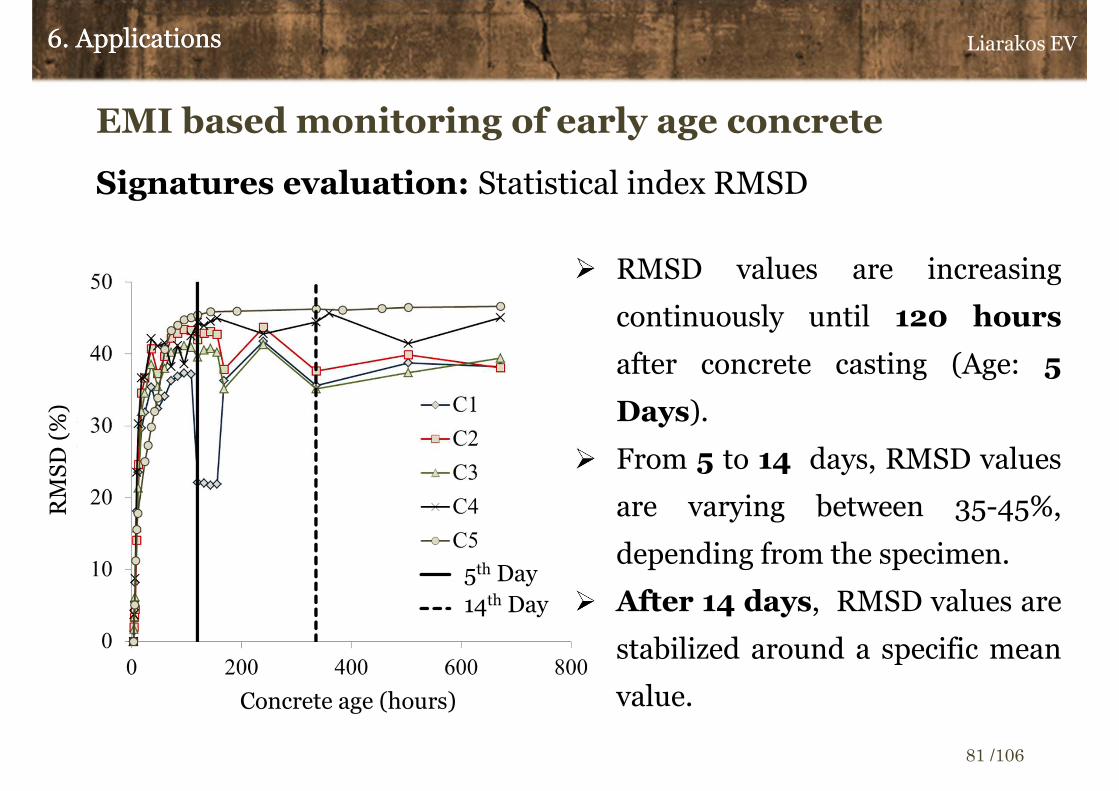
Signatures evaluation: Statistical index RMSD
6. Applications6. Applications
� RMSD values are increasing
continuously until 120 hours
after concrete casting (Age: 5
Days).
� From 5 to 14 days, RMSD values
are varying between 35-45%,
depending from the specimen.
� After 14 days, RMSD values are
stabilized around a specific mean
value.Concrete age (hours)
RM
SD
(%
)
5th Day
14th Day
Liarakos EV
81 /106

EMI based monitoring of early age concrete
Comparison between RMSD and concrete Young
Modulus, time-dependent evolution.
6. Applications6. Applications
� Ecm Model, Eurocode 2 [5.1].
� 5th Day: 87% of Εcm28
� 14th Day: 96% of Εcm28
[5.1] Bamforth P., Chisholm D., Gibbs J. and Harisson T., 2008. Properties of
concrete for use in EuroCode 2.
( )33.0
28 6721exp
−=
tcemEtE cmcm
Liarakos EV
82 /106
Ec
m(G
Pa
)
Ecm EC2 Model
5th Day
14th Day
Concrete age (hours)

EMI based monitoring of early age concrete
Monitoring of hydration process: 3-48 hours
� RMSD time rate is possible to be correlated with concrete’s
hydration rate and stiffness development rate (hardening) of
very early age concrete (<24hr).
� RMSD time rate indexes
6. Applications6. Applications
( )
( )
( )
( )
=
>−
−=
∆
∆
=
=
>−−
=∆
∆=
∑
∑
∑
∑
=−
=−
=
=
−
−
1,0
1,_
1,0
1,
11
11
1
1
1
1
n
ntt
RMSDRMSD
t
RMSD
tRMSDR
n
ntt
RMSDRMSD
t
RMSDtDRMSD
n
mmm
n
mmm
n
mm
n
mm
n
nn
nn
n
n
n
tn : Concrete age
corresponding to n-th
recorded signature.
t1: 3 hours (Reference
signature recording
time)
Liarakos EV
83 /106

EMI based monitoring of early age concrete
Monitoring of hydration process : DRMSD
6. Applications6. Applications
� Approximately from 3 to 7 hours
after cement and water mixing, it is
confirmed a rapid growth of
DRMSD.
� From 7 hours and until 24 there is
a normal decreasing of DRMSD
values.
� In period between 7 and 18 hours,
depending from specimen, DRMSD
index is receiving the maximum
value (peak).Concrete age (hours)
DR
MS
D
7-18 hours
Liarakos EV
84 /106

EMI based monitoring of early age concrete
Monitoring of hydration process : RMSD-R
6. Applications6. Applications
� Proportional behavior with DRMSD
index.
� RMSD-R curves are smoother than
DRMSD ones.
� Both DRMSD and RMSD-R
concrete age dependent evolution,
reflects the evolution of cement’s
hydration rate.
� Hydration rate is strongly related
with the rate of water-cement
crystals formation, as fresh concrete
is being hardened.
Concrete age (hours)
RM
SD
-R
7-18 hours
Liarakos EV
85 /106

6. Applications6. Applications
� C20/25 concrete cubic concrete specimen
� Edge length: 150mm
� Concrete age: 2 months
� Final strength after 7 compressive
loading-unloading cycles with scalar
increasing amplitude: 27.2 MPa
Concrete specimen compression
Monitoring of damage evolution in a concrete cubic
specimen under compression
Loading cycles
Compression load (kN)
Liarakos EV
86 /106

Monitoring of damage evolution in a concrete cubic
specimen under compression
� T-WiEYE System.
• Recording signature: EMI Ζ3.
• Calculation of mechanical impedance: ZSt.
• Frequency range: 10-65 kHz
� Evaluation of mechanical impedance signatures changes
• Reference signature: Real part of ΖSt signature which corresponds
to undamaged specimen (LC0).
• Residuals Statistical Control. Normal and GEV distributions.
• Simulation of reference signature utilizing mMIS method.
6. Applications6. Applications Liarakos EV
87 /106

Monitoring of damage evolution in a concrete cubic
specimen under compression
� EMI real part: R3 (Resistance).
6. Applications6. Applications Liarakos EV
88 /106
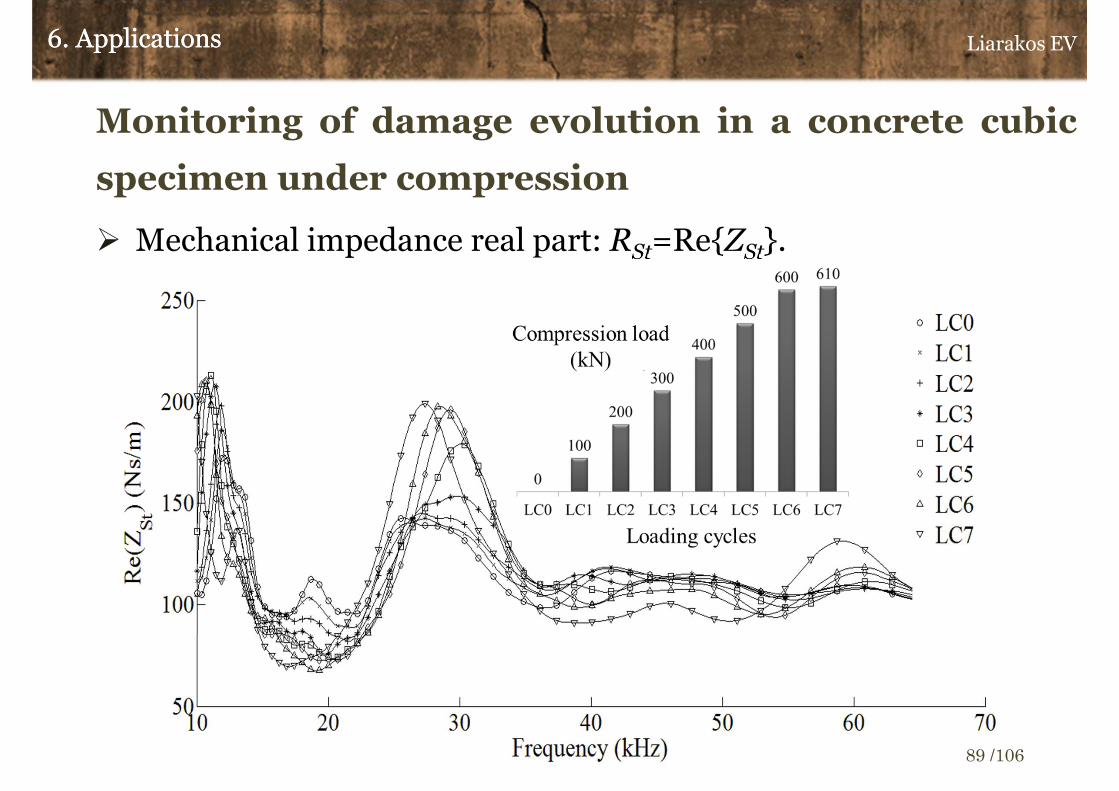
Monitoring of damage evolution in a concrete cubic
specimen under compression
� Mechanical impedance real part: RSt=Re{ZSt}.
6. Applications6. Applications Liarakos EV
89 /106

Monitoring of damage evolution in a concrete cubic
specimen under compression
� Reference signature simulation (mMIS model) RSmeas: ΖStmeas |LC0
6. Applications6. Applications
jfreq0,j
(kHz)
Ajeff
(mm2)
Hjeff
(mm)nj
st
1 24.91 0.10 45.82 0.03
2 31.09 0.40 36.71 0.06
3 29.02 0.37 39.32 0.06
4 24.64 11.89 46.31 0.38
5 40.21 1.50 28.38 0.13
6 42.94 0.07 26.57 0.03
7 33.32 3.05 34.24 0.30
8 44.90 1.12 25.41 0.14
9 51.99 0.05 21.95 0.05
10 59.96 0.52 19.03 0.12
11 62.78 0.01 18.17 0.01
RStmeas
RStest
+
freq (kHz)
RS
t=R
e{Z
St}
(N
s/m
)
Fitx=98.35%
Liarakos EV
90 /106

Monitoring of damage evolution in a concrete cubic
specimen under compression
� Statistical control of residuals: rLC0-7=(Rstmeas) LC0-7-RSt
est
6. Applications6. Applications
Certainty: 99%
Plow=0.005 ή 0.5 %
Pup=0.995 ή 99.5 %
Νout0= 2
Nout=150
Liarakos EV
91 /106

Monitoring of damage evolution in a concrete cubic
specimen under compression
Evaluation of damages evolution
6. Applications6. Applications
Certainty: 99%
Plow=0.005 ή 0.5 %
Pup=0.995 ή 99.5 %
Νout0= 2
Nout=150
Surficial micro-cracks
Total CollapseExtended cracks
Loading cycles
LC6 (600kN)
LC7 (610 kN)
Liarakos EV
92 /106
Monitoring of damage evolution in a concrete cubic
specimen under compression
Recover of TBSA after specimen’s failure
6. Applications6. Applications
Before embedding
After specimen’s collapse
/recovery
Frequency (kHz)
Res
ista
nce R
3(O
hm)
Liarakos EV
93 /106
Compression load (kN)
Loading cycles
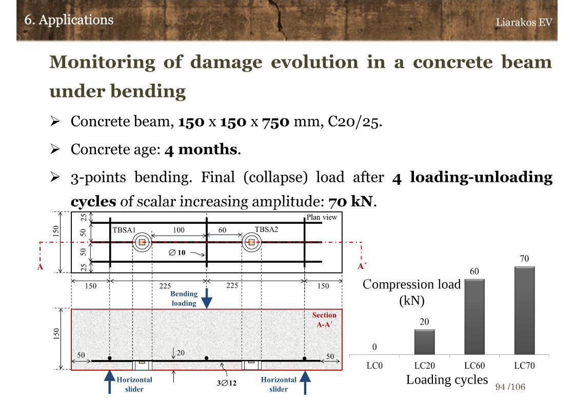
Monitoring of damage evolution in a concrete beam
under bending
� Concrete beam, 150 x 150 x 750 mm, C20/25.
� Concrete age: 4 months.
� 3-points bending. Final (collapse) load after 4 loading-unloading
cycles of scalar increasing amplitude: 70 kN.
6. Applications6. Applications Liarakos EV
94 /106

6. Applications6. Applications
Monitoring of damage evolution in a concrete beam
under bending
� Steel bar reinforcement only in tension zone
� TBSA bonding on reinforcement mesh
3 point bendingmachine
TBSAs and reinforcement mesh
Casting of concrete beam and TBSA embedding
TBSA 1 TBSA 2
TBSA 1
Liarakos EV
95 /106

Monitoring of damage evolution in a concrete beam
under bending
� T-WiEYE system.
• Recording signature: EMI Ζ3.
• Calculation of mechanical impedance: ZSt.
• Frequency range: 10-100 kHz
� Evaluation of mechanical impedance signatures changes
• Monitoring based only on TBSA 1
• Reference signature: Real part of ΖSt signature which corresponds
to undamaged specimen (LC0).
• Residuals Statistical Control. Normal and GEV distributions.
• Simulation of reference signature utilizing mMIS method.
6. Applications6. Applications Liarakos EV
96 /106

Monitoring of damage evolution in a concrete beam
under bending
� Mechanical impedance real part: RSt=Re{ZSt}.
6. Applications6. Applications Liarakos EV
97 /106

Monitoring of damage evolution in a concrete beam
under bending
� Reference signature simulation (mMIS model) RSmeas: ΖStmeas |LC0
6. Applications6. Applications
RStmeas
RStest
+
freq (kHz)
RS
t=R
e{Z
St}
(N
s/m
)
Fitx=98.35% jfreq0,j
(kHz)
Ajeff
(mm2)
Hjeff
(mm)nj
st
1 18.43 1.21 61.91 0.21
2 25.73 0.91 44.36 0.31
3 31.65 0.96 36.05 0.26
4 41.30 0.70 27.63 0.20
5 48.55 0.60 23.50 0.12
6 76.36 1.26 14.94 0.24
7 116.92 2.86 9.76 0.02
Liarakos EV
98 /106
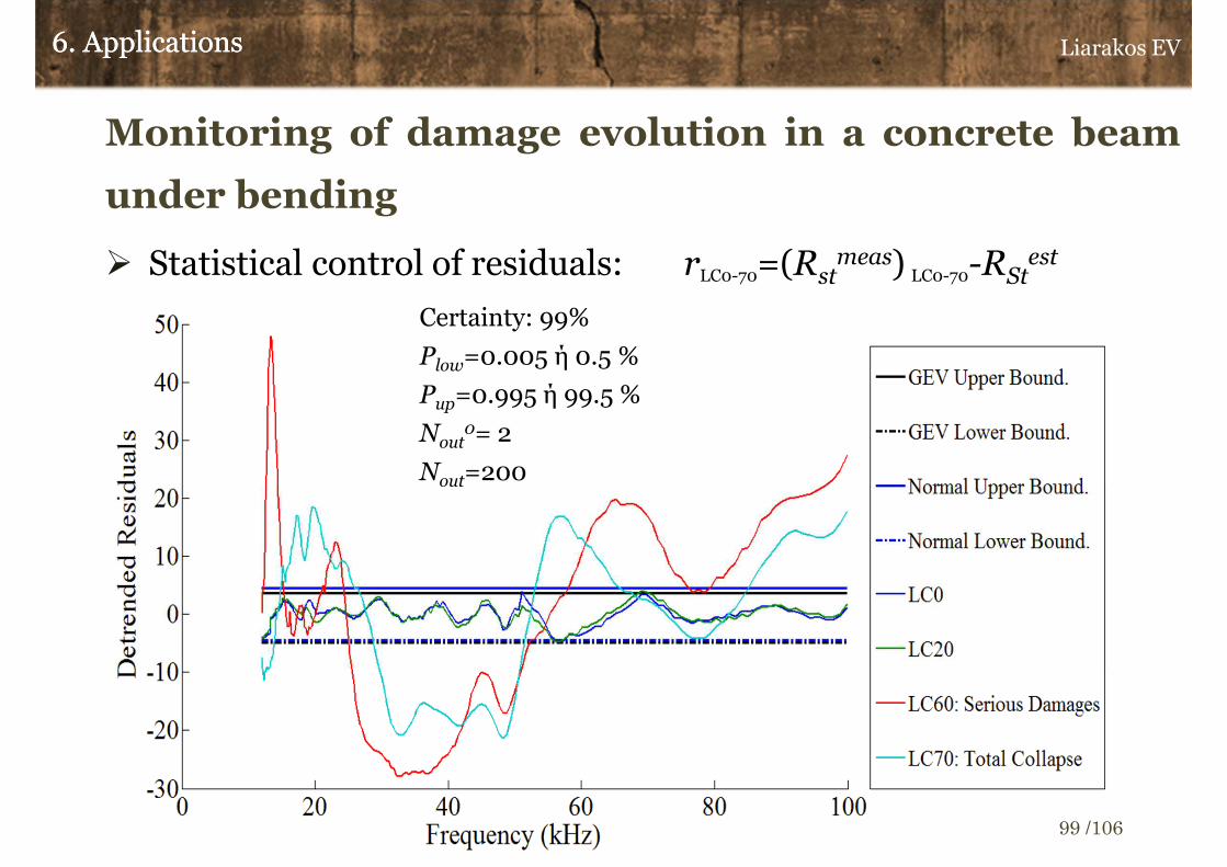
Monitoring of damage evolution in a concrete beam
under bending
� Statistical control of residuals: rLC0-70=(Rstmeas) LC0-70-RSt
est
6. Applications6. Applications
Βεβαιότητα: 99%
Pout=0.005 ή 0.5 %
Νout0= 2
F=200
Certainty: 99%
Plow=0.005 ή 0.5 %
Pup=0.995 ή 99.5 %
Νout0= 2
Nout=200
Liarakos EV
99 /106

Monitoring of damage evolution in a concrete beam
under bending
Evaluation of damage evolution: Shear failure
6. Applications6. Applications
Certainty: 99%
Plow=0.005 ή 0.5 %
Pup=0.995 ή 99.5 %
Νout0= 2
Nout=200
Shear cracks
starting
Shear crack extending –
Total collapse
Liarakos EV
100 /106

7.Conclusions and Proposals for future
work
Liarakos EV
101 /106

Conclusions
� Ceramic piezoelectric materials and especially PZT (Lead
Zirconate Titanate) have successfully adopted in non destructive
evaluation methods of concrete constructional elements.
� Based on theoretical analysis of mechanical interaction between
PZTs and Structures Under Monitoring (SUM), it could be
stated that the electrical response of a PZT is strongly related with
SUM’s dynamic response.
� Experimentally acquired Electro-Mechanical Impedance
(EMI) signatures in frequency domain, could be termed as the
dominant tool for the monitoring and evaluation of structures
dynamic response.
7. Conclusions and Proposals for future work7. Conclusions and Proposals for future work Liarakos EV
102 /106

Conclusions
� The dynamic response of a structure which is hosting one or more
PZTs, could be approximated semi-experimentally from PZTs
measured electrical response (EMI), based on theoretical models
that have been developed in context of present dissertation.
� Both the statistical indexes (RMSD, DRMSD, RMSD-R) and
residuals statistical control are contributing vitally in comparative
analysis of EMI signatures.
� Embedded piezoelectric SMart Aggregates (SMA) behave as
part of concrete's micro-structure, enabling the monitoring of
constructional members from the very early stages of hydration
and throughout their lifetime.
7. Conclusions and Proposals for future work7. Conclusions and Proposals for future work Liarakos EV
103 /106

Conclusions
� An integrated monitoring system which combines the
automatic EMI data acquisition and storage, with wireless
technology, contributes crucially in the following points :
• Remote control and continuous inspection of structural integrity.
• Effective acquisition and classification of large amount of data.
• Enables the development of an extended multi-SMA grid for the
holistic approach of large scale structures monitoring.
� Connection of MySQL's workspace with MATLAB's
environment, provides the possibility of immediate post-
processing of recording EMI data and time-effective evaluation
of structural integrity.
7. Conclusions and Proposals for future work7. Conclusions and Proposals for future work Liarakos EV
104 /106
Proposals for future work
� Improvement of Electro-Mechanical Systems response simulation
algorithms, by decreasing their complexity.
� Optimization of Teflon Based Smart Aggregate’s design, regarding to
its shape, PZT gluing adhesive and anchoring bolts set-up.
� Further development EMI data, post-processing MATLAB GUI, and
re-scripting of an executable MATLAB-independent application.
� Application of T-WiEYE system in monitoring of large scale concrete
structures.
� Investigation of the case where SMAs are applied in structures
passive control, acting exclusively as sensors (structure’s natural
vibration recording, without electrical voltage stimulation).
7. Conclusions and Proposals for future work7. Conclusions and Proposals for future work Liarakos EV
105 /106

Thank you for your
attention
Thank you for your
attention
Liarakos EV | Chania Jan. 2015.Liarakos EV | Chania Jan. 2015.