damage suffered by hanuman dhoka after the 2015 nepal
TRANSCRIPT

Damage suffered by Hanuman Dhoka after the
2015 Nepal Earthquakes
26 May 2015

2
1. Introduction
The current report presents findings by the ICCROM-ICOMOS-Smithsonian Institute team that visited some of the interior areas of Hanuman Dhoka after the April/May 2015 earthquakes on the 26th of May 2015. The purpose of the visit was to assess the stability conditions of the interior areas of Hanuman Dhoka in order to witness the overall damage of the movable heritage and to analyse the possibility of evacuating and rescuing it. The visit was requested by the Department of Archaeology of Nepal and the members of the ICCROM-ICOMOS-Smithsonian Institute team that visited the building were escorted by museum staff members. Given the high national significance of the Hanuman Dhoka palace and museum buildings, it is important that emergency stabilization of the heritage structures and collections is addressed in a holistic way. The aim of the first aid should be to assess and document damage using past documentation, prevent further damage and promote early recovery through prioritization of conservation treatments (of buildings and collections), and ensure business continuity through creative use/reuse while the stabilization and recovery work is underway. 2. Preliminary assessment of the structural safety of Hanuman Dhoka
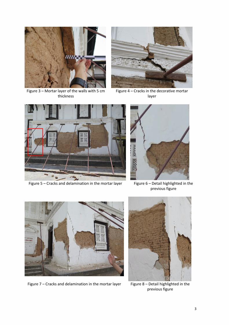
Before entering Hanuman Dhoka, a preliminary assessment of its structural safety was carried out from the exterior based on the visible damage to the building. This assessment was needed to support the decision of entering the building without implementing additional safety measures (e.g. shoring of the walls from the interior). The assessment was essentially based on engineering judgment and visual/qualitative assessment of the damage to the exterior walls. From this analysis, it was seen that the mortar layer that covers the walls has a large thickness, 4 to 4.5 cm, and that many of the visible cracks on the walls do not reflect structural damage. Instead, these cracks only reflect damage to the exterior mortar layer which is also detached from the actual wall structure in many places. It was also seen in many parts of the walls that the cracks in the mortar layer do not extend to the bricks of the wall structure. Figures 1 to 3 show different examples of the cracks in the exterior walls of Hanuman Dhoka that were analysed, while Figs. 4 to 8 show cases where the mortar layer cracks do not extend to the bricks of the wall structure.
Figure 1 – Mortar layer of the walls with 4.5 cm
thickness currently detached 3 cm from its support
Figure 2 – Mortar layer of the walls with 4 cm thickness currently detached 1 cm from its
support
3
Figure 3 – Mortar layer of the walls with 5 cm
thickness Figure 4 – Cracks in the decorative mortar
layer
Figure 5 – Cracks and delamination in the mortar layer Figure 6 – Detail highlighted in the
previous figure
Figure 7 – Cracks and delamination in the mortar layer Figure 8 – Detail highlighted in the previous figure
4
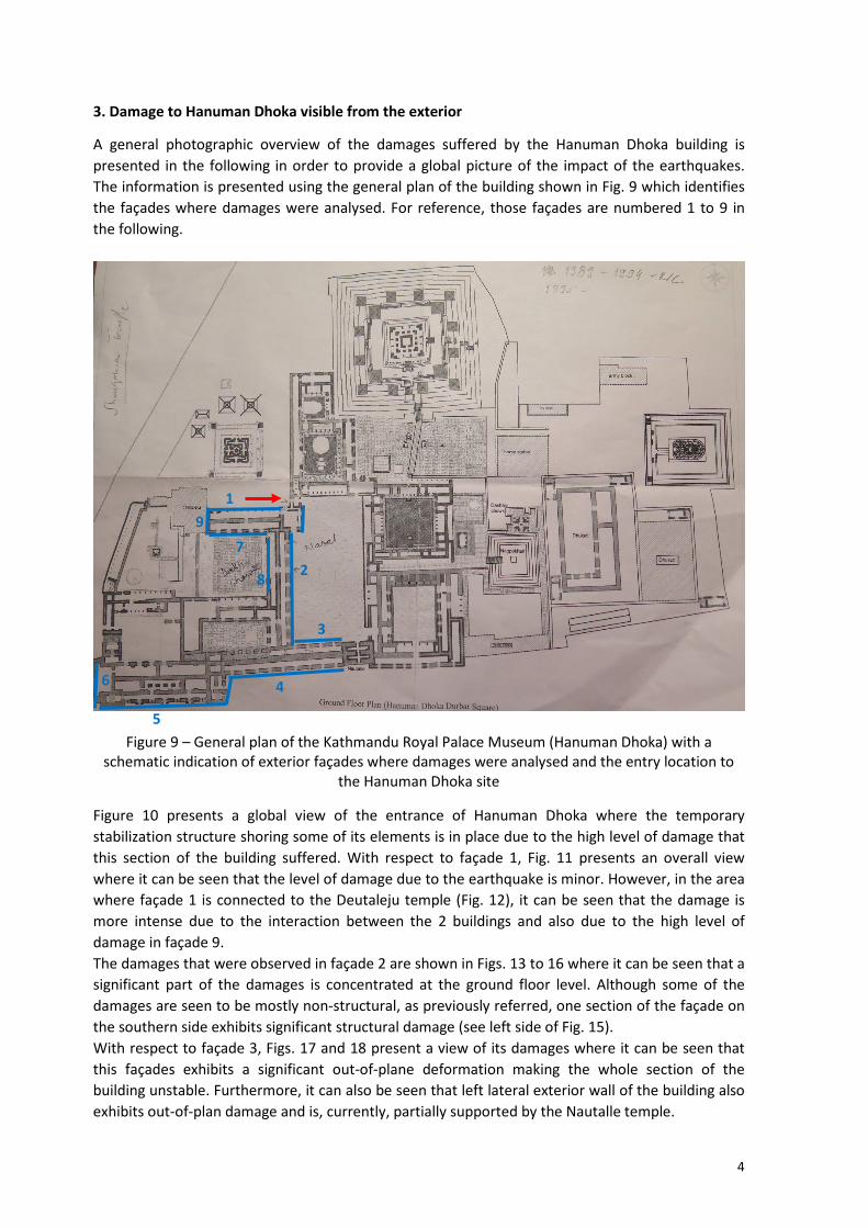
3. Damage to Hanuman Dhoka visible from the exterior
A general photographic overview of the damages suffered by the Hanuman Dhoka building is presented in the following in order to provide a global picture of the impact of the earthquakes. The information is presented using the general plan of the building shown in Fig. 9 which identifies the façades where damages were analysed. For reference, those façades are numbered 1 to 9 in the following.
Figure 9 – General plan of the Kathmandu Royal Palace Museum (Hanuman Dhoka) with a
schematic indication of exterior façades where damages were analysed and the entry location to the Hanuman Dhoka site
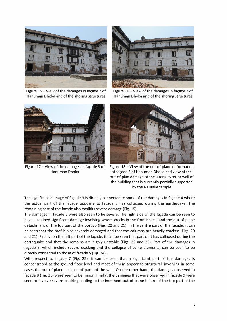
Figure 10 presents a global view of the entrance of Hanuman Dhoka where the temporary stabilization structure shoring some of its elements is in place due to the high level of damage that this section of the building suffered. With respect to façade 1, Fig. 11 presents an overall view where it can be seen that the level of damage due to the earthquake is minor. However, in the area where façade 1 is connected to the Deutaleju temple (Fig. 12), it can be seen that the damage is more intense due to the interaction between the 2 buildings and also due to the high level of damage in façade 9. The damages that were observed in façade 2 are shown in Figs. 13 to 16 where it can be seen that a significant part of the damages is concentrated at the ground floor level. Although some of the damages are seen to be mostly non-structural, as previously referred, one section of the façade on the southern side exhibits significant structural damage (see left side of Fig. 15). With respect to façade 3, Figs. 17 and 18 present a view of its damages where it can be seen that this façades exhibits a significant out-of-plane deformation making the whole section of the building unstable. Furthermore, it can also be seen that left lateral exterior wall of the building also exhibits out-of-plan damage and is, currently, partially supported by the Nautalle temple.
1
2
3
4
5
6
9 7
8

5
Figure 10 – View of the entrance of Hanuman Dhoka which is
shored due to its level of damage
Figure 11 – View of the damages in façade 1 of Hanuman
Dhoka Figure 12 – View of the damages in façade 1 of Hanuman Dhoka
and of the shoring of the Deutaleju temple
Figure 13 – View of the damages in façade 2 of Hanuman Dhoka and of the shoring structures
Figure 14 – View of the damages in façade 2 of Hanuman Dhoka and of the shoring structures
6
Figure 15 – View of the damages in façade 2 of Hanuman Dhoka and of the shoring structures
Figure 16 – View of the damages in façade 2 of Hanuman Dhoka and of the shoring structures
Figure 17 – View of the damages in façade 3 of
Hanuman Dhoka Figure 18 – View of the out-of-plane deformation
of façade 3 of Hanuman Dhoka and view of the out-of-plan damage of the lateral exterior wall of the building that is currently partially supported
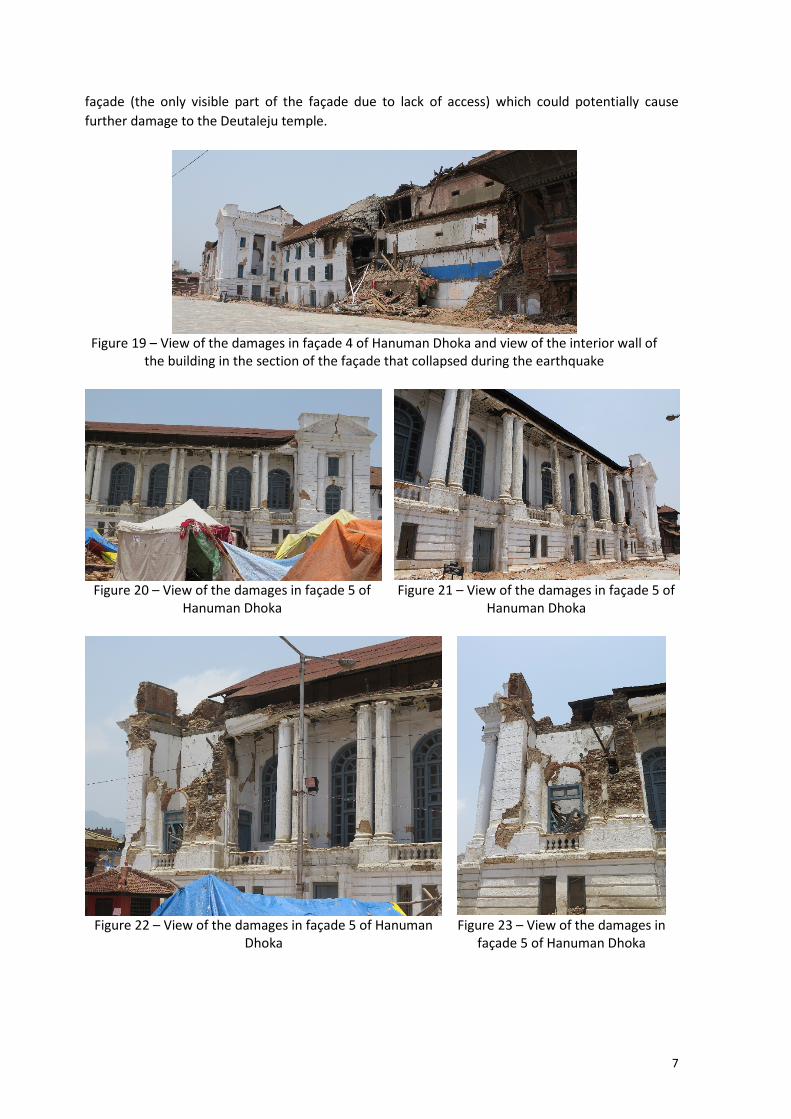
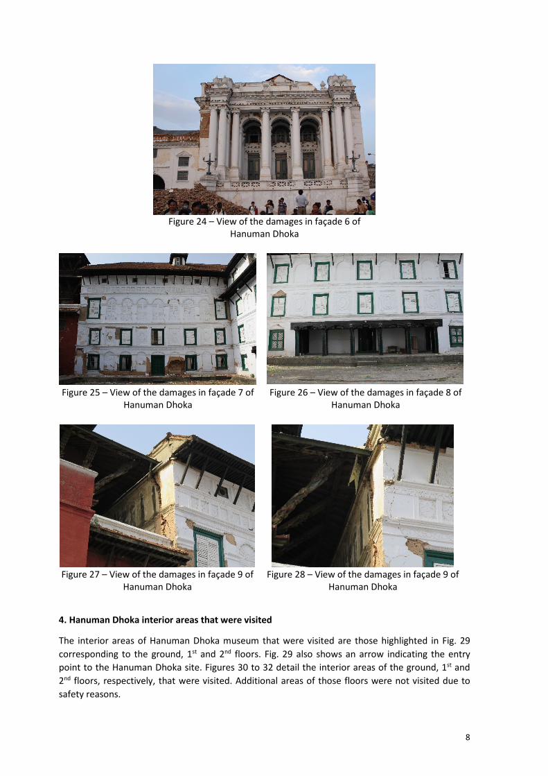
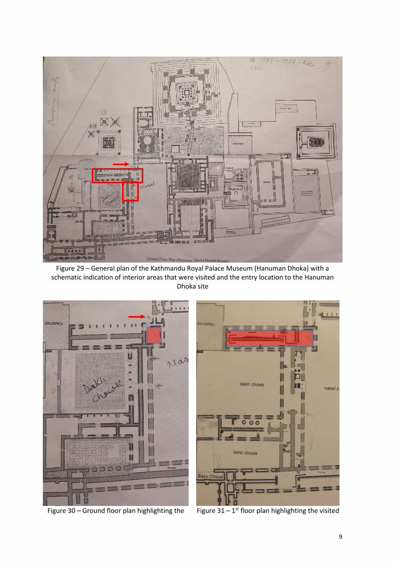
by the Nautalle temple The significant damage of façade 3 is directly connected to some of the damages in façade 4 where the actual part of the façade opposite to façade 3 has collapsed during the earthquake. The remaining part of the façade also exhibits severe damage (Fig. 19). The damages in façade 5 were also seen to be severe. The right side of the façade can be seen to have sustained significant damage involving severe cracks in the frontispiece and the out-of-plane detachment of the top part of the portico (Figs. 20 and 21). In the centre part of the façade, it can be seen that the roof is also severely damaged and that the columns are heavily cracked (Figs. 20 and 21). Finally, on the left part of the façade, it can be seen that part of it has collapsed during the earthquake and that the remains are highly unstable (Figs. 22 and 23). Part of the damages in façade 6, which include severe cracking and the collapse of some elements, can be seen to be directly connected to those of façade 5 (Fig. 24). With respect to façade 7 (Fig. 25), it can be seen that a significant part of the damages is concentrated at the ground floor level and most of them appear to structural, involving in some cases the out-of-plane collapse of parts of the wall. On the other hand, the damages observed in façade 8 (Fig. 26) were seen to be minor. Finally, the damages that were observed in façade 9 were seen to involve severe cracking leading to the imminent out-of-plane failure of the top part of the
7
façade (the only visible part of the façade due to lack of access) which could potentially cause further damage to the Deutaleju temple.
Figure 19 – View of the damages in façade 4 of Hanuman Dhoka and view of the interior wall of
the building in the section of the façade that collapsed during the earthquake
Figure 20 – View of the damages in façade 5 of
Hanuman Dhoka Figure 21 – View of the damages in façade 5 of
Hanuman Dhoka
Figure 22 – View of the damages in façade 5 of Hanuman
Dhoka Figure 23 – View of the damages in
façade 5 of Hanuman Dhoka
8
Figure 24 – View of the damages in façade 6 of
Hanuman Dhoka
Figure 25 – View of the damages in façade 7 of
Hanuman Dhoka Figure 26 – View of the damages in façade 8 of
Hanuman Dhoka
Figure 27 – View of the damages in façade 9 of
Hanuman Dhoka Figure 28 – View of the damages in façade 9 of
Hanuman Dhoka
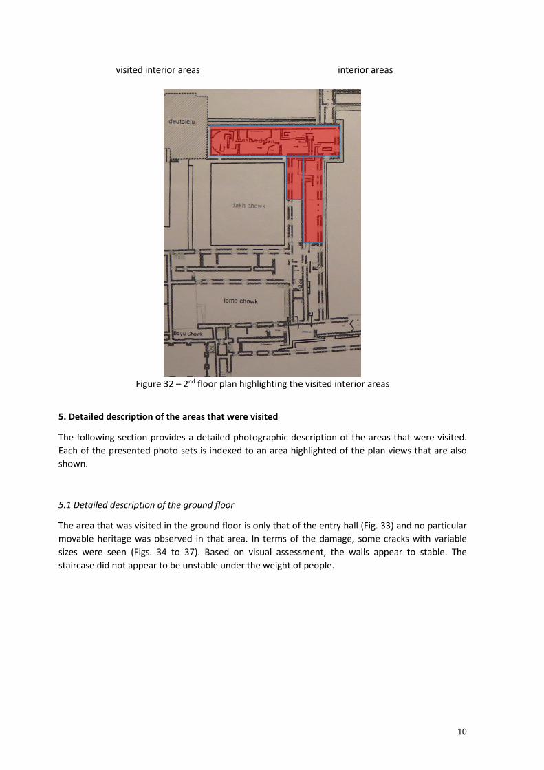
4. Hanuman Dhoka interior areas that were visited
The interior areas of Hanuman Dhoka museum that were visited are those highlighted in Fig. 29 corresponding to the ground, 1st and 2nd floors. Fig. 29 also shows an arrow indicating the entry point to the Hanuman Dhoka site. Figures 30 to 32 detail the interior areas of the ground, 1st and 2nd floors, respectively, that were visited. Additional areas of those floors were not visited due to safety reasons.
9
Figure 29 – General plan of the Kathmandu Royal Palace Museum (Hanuman Dhoka) with a
schematic indication of interior areas that were visited and the entry location to the Hanuman Dhoka site
Figure 30 – Ground floor plan highlighting the Figure 31 – 1st floor plan highlighting the visited
10
visited interior areas interior areas
Figure 32 – 2nd floor plan highlighting the visited interior areas
5. Detailed description of the areas that were visited
The following section provides a detailed photographic description of the areas that were visited. Each of the presented photo sets is indexed to an area highlighted of the plan views that are also shown.
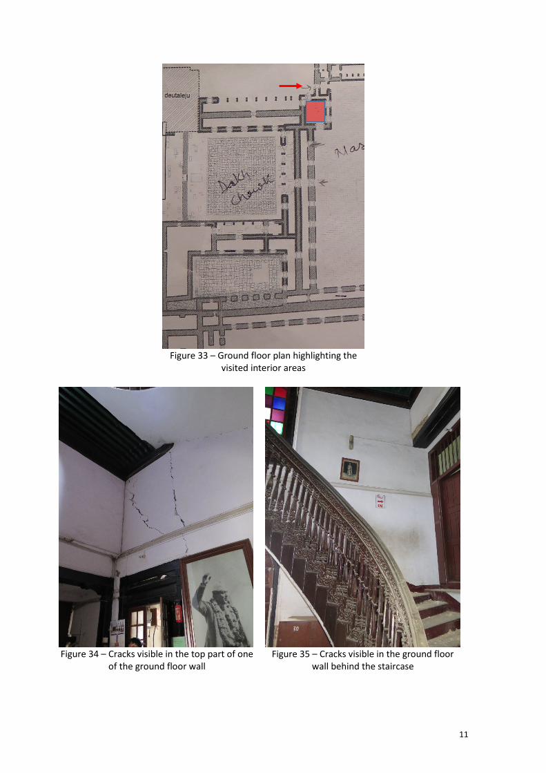
5.1 Detailed description of the ground floor
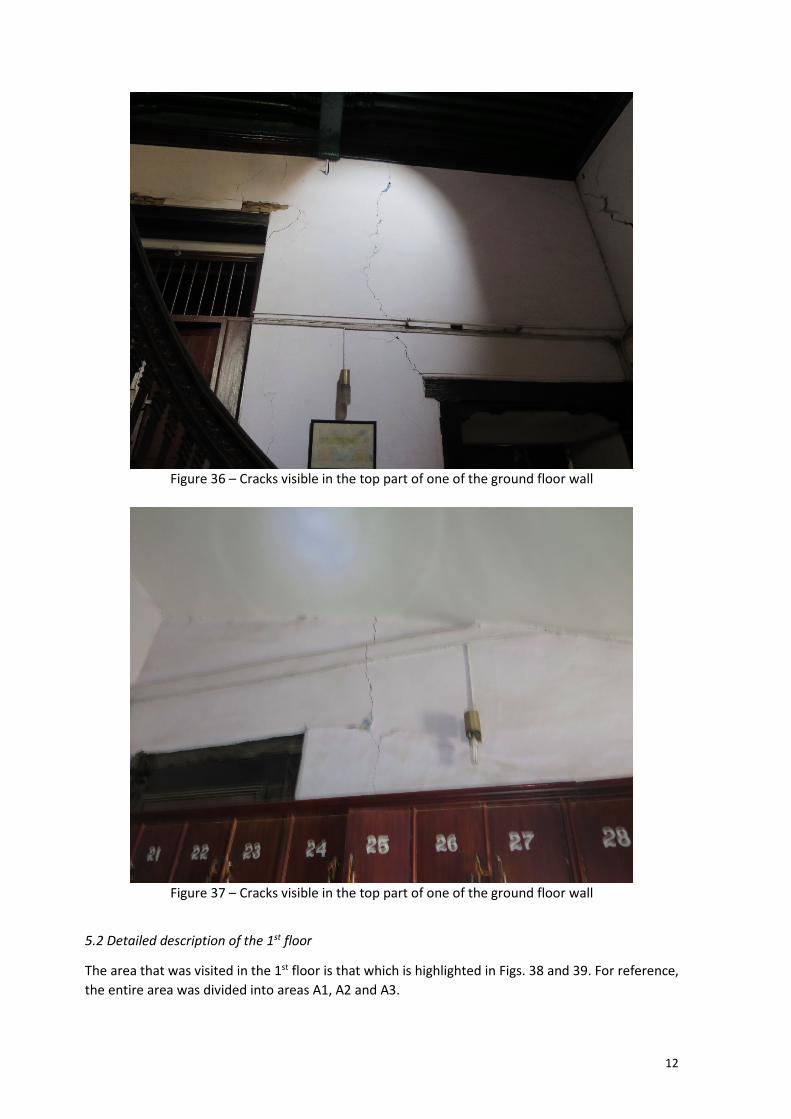
The area that was visited in the ground floor is only that of the entry hall (Fig. 33) and no particular movable heritage was observed in that area. In terms of the damage, some cracks with variable sizes were seen (Figs. 34 to 37). Based on visual assessment, the walls appear to stable. The staircase did not appear to be unstable under the weight of people.
11
Figure 33 – Ground floor plan highlighting the
visited interior areas
Figure 34 – Cracks visible in the top part of one
of the ground floor wall Figure 35 – Cracks visible in the ground floor
wall behind the staircase
12
Figure 36 – Cracks visible in the top part of one of the ground floor wall
Figure 37 – Cracks visible in the top part of one of the ground floor wall
5.2 Detailed description of the 1st floor
The area that was visited in the 1st floor is that which is highlighted in Figs. 38 and 39. For reference, the entire area was divided into areas A1, A2 and A3.

13
Figure 38 – 1st floor plan of the visited interior areas
Figure 39 – 1st floor plan with the visited areas divided into areas A1, A2 and A3
Area A1 corresponds to a small exhibition room (Figs. 40 and 41) which includes some movable heritage items which appeared to be undamaged. From the safety point of view, it is referred that the floor did not appear to have unsafe deformations when people walked on top of it. Furthermore, the walls and ceiling exhibited a few cracks but it was not possible to determine if they were structural or non-structural cracks.
Figure 40 – 1st floor plan of areas A1 and A2 Figure 41 – 1st floor area A1
Area A2 corresponds to the north side of the exhibition wing on the west part of the floor (Fig. 40) which includes several movable heritage items on display. Most of the objects were seen to be
A1 A2
A1 A2
A3

14
standing on their places and appeared to be undamaged. Display cabinets having glass windows were intact. From the safety point of view, it is referred that the floor did not appear to have unsafe deformations when people walked on top of it. Furthermore, the walls and ceiling exhibited a few cracks but it was not possible to determine if they were structural or non-structural cracks. In order to illustrate these findings, Figs. 42 and 47 present several photos of area A2 taken during the visit.
Figure 42 – 1st floor plan A2 area Figure 43 – 1st floor plan A2 area
Figure 44 – 1st floor plan A2 area Figure 45 – 1st floor plan A2 area

15
Figure 46 – 1st floor plan A2 area Figure 47 – 1st floor plan A2 area
Area A3 corresponds to the south side of the exhibition wing on the west part of the floor (Fig. 48) which also includes several movable heritage items on display. As for area A2, most of the objects were seen to be standing on their places and appeared to be undamaged except for one painting that was seen to be on the floor in the area where A2 connects to A3. Display cabinets having glass windows were also seen to be intact. From the safety point of view, it is referred that the floor did not appear to have unsafe deformations when people walked on top of it. Furthermore, the walls and ceiling exhibited a few cracks but it was not possible to determine if they were structural or non-structural cracks. In order to illustrate these findings, Figs. 49 and 55 present several photos of area A3 taken during the visit.
Figure 48 – 1st floor plan A3 area Figure 49 – 1st floor plan A3 area
A3

16
Figure 50 – 1st floor plan A3 area Figure 51 – 1st floor plan A3 area
Figure 52 – 1st floor plan A3 area Figure 53 – 1st floor plan A3 area
Figure 54 – 1st floor plan A3 area Figure 55 – 1st floor plan A3 area

17
Figure 56 – Access from 1st to 2nd floor Figure 57 – Access from 1st to 2nd
floor
Figure 58 – Access from 1st to 2nd floor Figure 59 – Access from 1st to 2nd floor
5.3 Detailed description of the 2nd floor
The area that was visited in the 2nd floor is that which is highlighted in Fig. 60 . For reference, the entire area was divided into areas B1, B2, B3 and B4.
Area B1 corresponds to a lobby area (Figs. 61 and 62) and also includes a small exhibition room (Fig. 63). From the safety point of view, it is referred that the floor did not appear to have unsafe deformations when people walked on top of it. Furthermore, the walls and ceiling exhibited a few cracks but it was not possible to determine if they were structural or non-structural cracks.
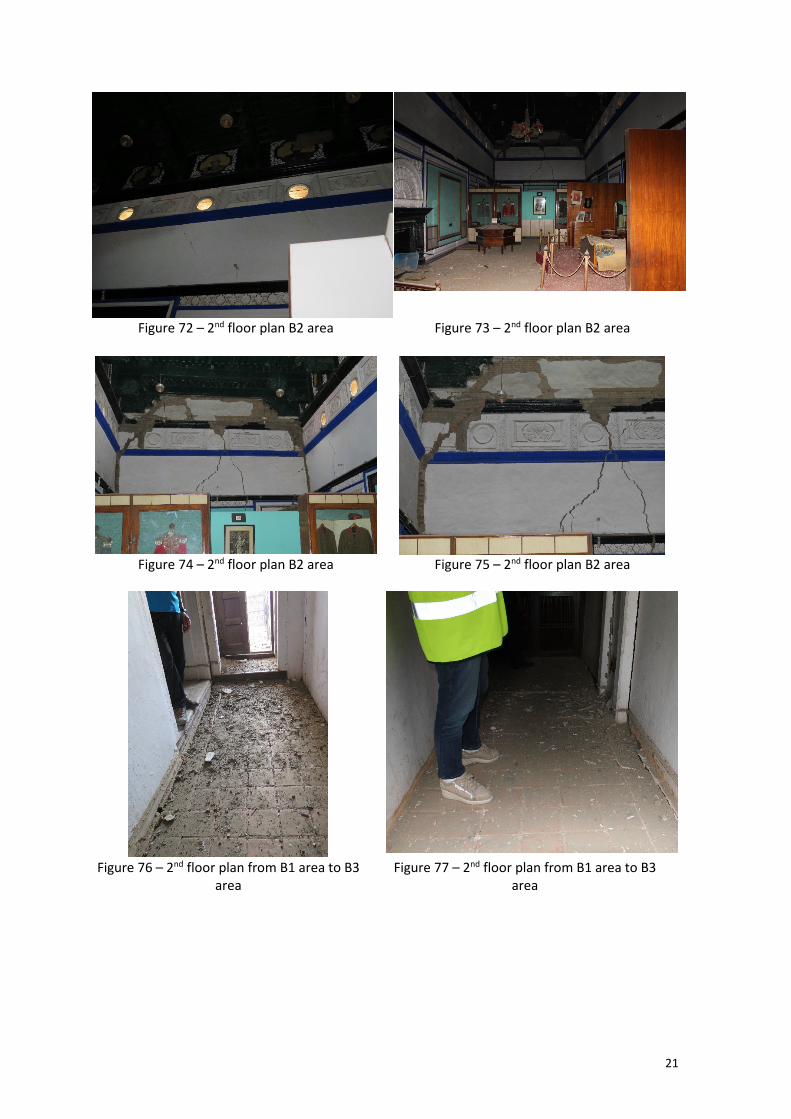
Area B2 corresponds to a large exhibition room on the west part of the floor (Fig. 60 ) which includes several movable heritage items on display. Due to the size of the room and to the fact that part of the walls and ceiling exhibited important cracks which appeared to be structural, only part of the room was visited for safety reasons. On the part that was visited, most of the objects were seen to be standing on their places and appeared to be undamaged. Display cabinets having glass windows were intact. From the safety point of view, it is also referred that the floor did not appear to have unsafe deformations when people walked on top of it. In order to illustrate these findings, Figs. 64 to 75 present several photos of area B2 taken during the visit.
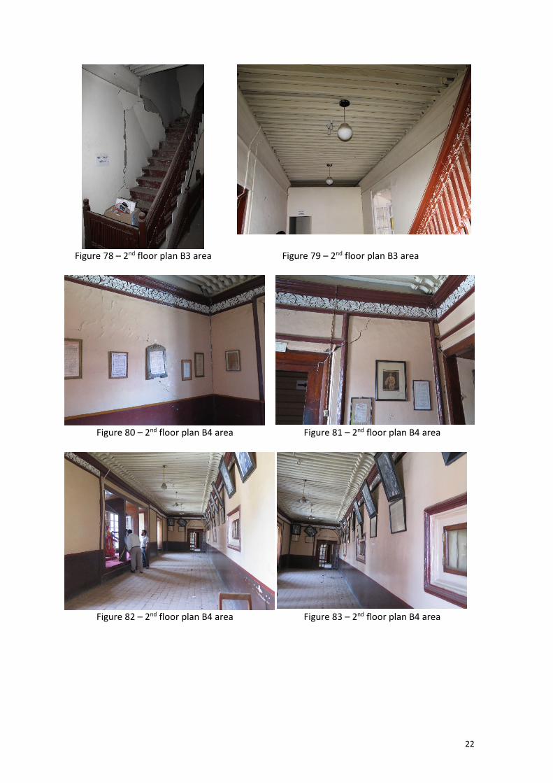
On the way to area B3, the corridor connecting areas B1 and B3 was seen to exhibit cracks on the floor, near the walls (Figs. 76 and 77). Area B3 corresponds to a lobby area giving access to an office and to staircase to the 3rd floor. From the safety point of view, the area close to the staircase (Figs.

18
78 and 79) exhibited important cracks in the wall. Still, the floor did not appear to have unsafe deformations when people walked on top of it and the ceiling exhibited a few cracks whose severity was not possible to determine.
Area B4 corresponds to a long exhibition wing room on the east part of the floor (Fig. 60 ) which includes several movable heritage items on display. Due to the size of the wing and to the fact that part of the walls and ceiling in the southern part exhibited important cracks which appeared to be structural, only part of the wing was visited for safety reasons. On the part that was visited, most of the objects were seen to be standing on their places and appeared to be undamaged. Display cabinets having glass windows were intact. From the safety point of view, it is also referred that the floor did not appear to have unsafe deformations when people walked on top of it, although it exhibited a visible deformation. In order to illustrate these findings, Figs. 80 to 85 present several photos of area B4 taken during the visit.
Figure 60 – 2nd floor plan of the visited areas
divided into areas B1, B2, B3 and B4 Figure 61 – 2nd floor plan B1 area
B2
B4
B3
B1

19
Figure 62 – 2nd floor plan B1 area Figure 63 – 2nd floor plan B1 area
Figure 64 – 2nd floor plan B2 area Figure 65 – 2nd floor plan B2 area

20
Figure 66 – 2nd floor plan B2 area Figure 67 – 2nd floor plan B2 area
Figure 68 – 2nd floor plan B2 area Figure 69 – 2nd floor plan B2 area. Detail of previous figure
Figure 70 – 2nd floor plan B2 area Figure 71 – 2nd floor plan B2 area. Detail of
previous figure
21
Figure 72 – 2nd floor plan B2 area Figure 73 – 2nd floor plan B2 area
Figure 74 – 2nd floor plan B2 area Figure 75 – 2nd floor plan B2 area
Figure 76 – 2nd floor plan from B1 area to B3
area Figure 77 – 2nd floor plan from B1 area to B3
area
22
Figure 78 – 2nd floor plan B3 area Figure 79 – 2nd floor plan B3 area
Figure 80 – 2nd floor plan B4 area Figure 81 – 2nd floor plan B4 area
Figure 82 – 2nd floor plan B4 area Figure 83 – 2nd floor plan B4 area

23
Figure 84 – 2nd floor plan B4 area Figure 85 – 2nd floor plan B4 area
6. Main findings and conclusions
The main findings of the visit carried out by the ICCROM-ICOMOS team to the interior areas of Hanuman Dhoka on the 26th of May 2015 are the following:
• Most of the movable heritage seems to be undamaged. • Based on the visual assessment that was carried out, some of the interior areas that were visited
only exhibited light damage levels in walls and ceilings (see Figs. 86 to 88). • Based on the visual assessment that was carried out, some of the interior areas that were visited
exhibited medium/intense damage levels in walls and ceilings (see Fig. 88).
The main conclusions of the visit are:
• The visual safety assessment carried out during the visit revealed that a part of the museum movable heritage can be safely retrieved before undertaking detailed stabilization work for the structure (see areas highlighted in yellow in Figs. 86 to 88). However, this should be done in coordination with structural engineers.
• Parts of the building (see areas highlighted in orange in Fig. 88) have suffered medium/high structural damage and appear to be unstable. Some important artefacts are housed in these areas and their retrieval requires special operation that will need internal shoring before evacuation.
• Parts of the building that were not visited for safety reasons (see areas highlighted in red in Fig. 88) have suffered extensive structural damage and appear to be unstable. Some important artefacts are housed in these areas and their retrieval requires special operation that will need a detailed assessment of the safety conditions and internal shoring before evacuation.

24
Figure 86 – Damages in the ground floor areas
that were visited
Figure 87 – Damages in the 1st floor areas that were visited

25
Figure 88 – Damages in the 2nd floor areas that were visited
Xavier Romão
Esmeralda Paupério
Arun Menon
Rohit Jigyasu
Aparna Tandon
Corine Wegener