damage to aircraft composite structures caused by directed
TRANSCRIPT
lable at ScienceDirect
Defence Technology 17 (2021) 1269e1288
Contents lists avai
Defence Technology
journal homepage: www.keaipubl ishing.com/en/ journals /defence-technology
Damage to aircraft composite structures caused by directed energysystem: A literature review
Y.X. Zhang*, Zhi Zhu, Richardson Joseph, Isfakul Jamal ShihanSchool of Engineering, Western Sydney University, Kingswood, NSW, 2751, Australia
a r t i c l e i n f o
Article history:Received 1 June 2020Received in revised form24 July 2020Accepted 16 August 2020Available online 26 August 2020
Keywords:AircraftComposite structuresDamage mechanismsDirect energy systemLaser systemExperimentNumerical studies
* Corresponding author.E-mail address: [email protected] review under responsibility of China Ordnan
https://doi.org/10.1016/j.dt.2020.08.0082214-9147/© 2020 China Ordnance Society. PublishingND license (http://creativecommons.org/licenses/by-n
a b s t r a c t
This paper presents a comprehensive review of the research studies on direct energy system effect onaircraft composite structures to develop a good understanding of state-of-the-art research and devel-opment in this area. The review begins with the application of composite materials in the aircraftstructures and highlights their particular areas of application and limitations. An overview of directedenergy system is given. Some of the commonly used systems in this category are discussed and theworking principles of laser energy systems are described. The experimental and numerical studies re-ported regarding the aircraft composite structures subject to the effect of directed energy systems,especially the laser systems are reviewed in detail. In particularly, the general effects of laser systems andthe relevant damage mechanisms against the composite structures are reported. The review drawsattention to the recent research and findings in this field and is expected to guide engineers/researchersin future theoretical, numerical, and experimental studies.© 2020 China Ordnance Society. Publishing services by Elsevier B.V. on behalf of KeAi Communications
Co. Ltd. This is an open access article under the CC BY-NC-ND license (http://creativecommons.org/licenses/by-nc-nd/4.0/).
1. Introduction
Composite materials have been widely used in aircraft in-dustries due to their excellent strength/stiffness to weight ratio,leading to significant weight reduction and strength improvementfor the aircraft structures. In addition, composite materials offerexcellent fatigue and corrosion resistance [1]. Composite materialscaught attention in military applications before their commercialuse [2]. They have been widely used in military aircrafts, and themost desirable aspect of weight reductionwould render the aircraftto carry more weapons and increase its range.
Directed energy systems are relatively new weapon systemsthat have been developed. These systems have seen applications inbattle field, and have been used to attack unmanned air vehicles(UAVs) and helicopters. With further development, these systemswill be used even more widely. In general, all weapons in one wayor another are devices that deposit energy in targets to achieve acertain type of damage. Directed energy systems are defined as thesystems in which a beam of concentrated electromagnetic energy
u (Y.X. Zhang).ce Society
services by Elsevier B.V. on behalfc-nd/4.0/).
or atomic or subatomic particles are used to degrade, damage, orcompletely destroy the targets. Directed energy systems arebroadly classified into three main categories: 1) lasers systems,which use an intensely focused beam of energy to destroy objectsor to dazzle or to disorient peoples; 2) systems which use elec-tromagnetic waves of other wavelengths such as microwaves; and3) systems which use particle beams to damage the target. It isimportant to provide adequate guidance and reference for engi-neers/researchers in analysis and design of composite aircraftsagainst the attack from direct energy systems.
To better understand the effect of the direct energy systems onthe aircrafts and the relevant damage mechanisms on the com-posite structures, a large number of research studies have beenconducted. This paper presents a comprehensive review of theresearch studies on direct energy system effect on aircraft com-posite structures to develop a good understanding of state-of-the-art research and development in this area. This paper focuses onthe experimental and numerical studies of aircraft compositestructures subject to the effect of laser energy systems. Theexperimental studies reported include the studies and experi-mental techniques investigating the thermos-mechanical response,the ablation behaviour caused by laser energy dissipating in theplasma layer near the target surface, the interlaminar damagemechanism and other damage mechanism of various composites
of KeAi Communications Co. Ltd. This is an open access article under the CC BY-NC-
Y.X. Zhang et al. / Defence Technology 17 (2021) 1269e12881270
(CFRP, GFRP, etc). The effects from both single laser loading andcombined laser and mechanical loading are included. Numericalstudies reviewed include the thermal-mechanical response, abla-tion behaviour, interlaminar effects and dynamic response ofcomposite materials under laser irradiations. This review is ex-pected to guide engineers/researchers for future theoretical, nu-merical, and experimental studies.
The paper begins with the introduction of the application ofcomposite materials in the aircraft structures and their particularapplication and limitations as presented in Section 2. An overviewof directed energy systems is given in Section 3, with the commonlyused systems discussed and the working principles of laser energysystems described especially. The experimental studies relating tothe laser system effects on the aircraft composite structures arereviewed in Section 4. The numerical studies using finite elementmethod to simulate the direct energy system effect on compositestructures are presented in Section 5. Finally, the review is sum-marized in Section 6 with recommendations of future research.
2. Composite application in aircraft structures
In general, three groups of composite materials have beendeveloped for aircraft industries [2], including Fibre-ReinforcedPlastics (FRPs), Fibre-Reinforced Metal Laminates (FRMLs), andMetal Matrix Composites (MMCs).
2.1. Fibre-Reinforced Plastics (FRPs)
Due to the requirements of high mechanical, chemical andthermal material properties, the demand of fibre-reinforced com-posites to replace the metal alloy materials started since the end ofthe 1960s. The fibres used are usually carbon, glass, Kevlar or thecombination of these, while thermosetting epoxy is generally usedas the matrix material in fibre-reinforced composites. Fibre-reinforced composites have been used increasingly in civilianaircraft applications in recent decades. Extensive applications ofthese types of composites are usually seen in Boeing 757, 767, 777,787 and Airbus A310, A320, A330, A340 and A350. For example, thefibre-reinforced composites have been used in the fuselage ofBoeing 787 Dreamliner, and the outer and centrewing box, fuselageand the empennage from the Airbus A350 XWB airframe [3].
Carbon Fibres Reinforced Plastics (CFRPs) and Glass FibresReinforced Plastics (GFRPs) are used in modern fighter aircraftssuch as the Lockheed Martin F-35 Lightning II. Their particularareas of application are in the load-bearing structures such asvertical stabilizer, tailplane, flaps and wings skin. Future militarycargo Airbus A400 M, C17 (USA), JSF or F35 (USA) and EFA (Europe)contains up to 40% of composites in the structural mass, coveringaround 70% of the surface area of the aircraft [4]. Another class offibre used in the FRPs is Kevlar, which is known for its extremelyhigh strength, low specific weight, outstanding thermal propertiesand dimensional stability. Kevlar has been used in the rotor bladesof the American helicopter Boeing AH-64 Apache, however, its usein aircraft industries is rather limited due to the high cost associ-ated with it.
Although FRPs offer advantages in terms of weight reductions,corrosion resistance, improved fatigue life and use of fewer numberof components (lesser no. of fasteners in particular) in the aircrafts,there are some inherent disadvantages, such as environmentaldegradation, material and processing costs, impact damage anddamage tolerance [5e7].
2.2. Fibre-Reinforced Metal Laminates (FRMLs)
Although the application of advanced aluminium alloys and
fibre reinforced composites has potential to reduce the cost ofaircrafts, they have their corresponding advantages and disadvan-tages. For instance, aluminium alloys offer poor fatigue strengthwhile fibre-reinforced composites have lower fracture toughness.In order to overcome the disadvantages of these classes of mate-rials, the idea to develop hybrid composite structural material wasinitiated [8]. As a result, FRMLs are developed using the advantagesof both alloys and fibre reinforced composites, in which the com-posite laminates are adhesively bonded to thin metal sheets [9].
FRMLs are broadly classified into two main categories, i.e. 1)FRMLs with aluminium alloys and 2) FRMLs with alternate metalalloys. Some of the commonly used FRMLs with aluminium alloysare Aramid Reinforced Aluminium Laminate (ARAL), Glass Rein-forced Aluminium Laminate (GLARE) and Carbon ReinforcedAluminium Laminate (CARALL). On the other hand, FRMLs withalternate metal alloy include titanium based FRMLs and magne-sium based FRMLs [10]. The most commonly used type of FRML inthe aircraft industry is GLARE, which was employed in the bulkcargo floors on Boeing 777, United airlines Boeing 737 and 757aircraft, and all Boeing aircraft at QANTAS. It was also employed inMidwest Express DC9, explosion hardens LD3 containers, Laser Jet45 forward bulkhead, AT&T aircraft electronics cabinets, and thefuselage on the A380 Airbus [11]. In the context of the militaryapplication, in which higher fracture toughness is desirable, GLAREwas found to exhibit outstanding fracture toughness during bullethole calibre penetration [12,13]. FRMLs offer low moisture ab-sorption, however, the main disadvantage associated with FRLMs isthe weak adhesive and cohesive strength between laminas.Economically, the cost of FRMLs is five to ten times of that of atraditional aluminium alloy used in the aircraft industry, but theycan reduce the overall structure weight by 20% [1].
2.3. Metal Matrix Composites (MMCs)
MMCs, which are metals or metals alloys that incorporate par-ticles, whiskers or fibres of different materials, offer unique prop-erties suitable to specific design needs [14]. In the context of theaircraft industry, the materials with lower specific weights are usedas matrix materials such as aluminium, magnesium, copper, silver,tin, lead, titanium, intermetals (NiAl, Ni3Al, Ti3Al, TiAl, MoSi2), andsuperalloys. MMCs were used in the 5th generation aircraftLockheed Martin F-22 Raptor and the heavy transport plane BoeingC-17 Globemaster III. MMC composite based on alloy TiAl6V4 andcontinuous fibre made of silicon carbide was used in the turbineaircraft engine. In Ref. [2], the composites were made from themetal matrix and reinforced with a very fine ceramic or metallicparticle with a diameter of 0.01e0.1 mm to about 15% of the com-posite volume. MMC composite B-Al (Boron-Aluminium) type oflaminates was used on the leading edges of main and tail rotorblades of helicopters: Sikorsky S-76D, Sikorsky S-92 or Sikorsky S-70 [15].
MMCs are ideal materials where high strength and excellentthermal properties are required. They are extremely reliable forcomponents which are subjected to higher thermal andmechanicalloadings. However, the use of MMCs is restricted due to theextremely higher cost associated with them. Some of thecommonly used MMCs configurations are presented in Table 1.
3. Directed energy system (DES)
The three types of directed energy system and their workingprinciple are introduced in this section with a focus on the lasersystem.
Table 1Different fibre-matrix configurations for MMCs [2,14,16].
Matrix Fibres
Continuous Discontinuous Whiskers Particulate
Aluminium Boron, Silicon carbide, Alumina, Graphite Alumina, Alumina-silica
Siliconcarbide
Silicon carbide, Boron carbide
Magnesium Graphite, alumina Siliconcarbide
Silicon carbide, Boron carbide
Titanium Silicon carbide, Coated boron Titanium carbideCopper Graphite, Silicon carbide, Niobium-titanium (wires), Niobium-tin
(wires)Silicon carbide, Boron carbide, Titaniumcarbide
Y.X. Zhang et al. / Defence Technology 17 (2021) 1269e1288 1271
3.1. Working principles and types of DES
3.1.1. LasersThe acronym laser stands for “light amplification through
stimulating emission of radiation”, and the laser system is consid-ered as a device that produces a highly energetic and intense beamof electromagnetic light. Laser light has the following qualities [16]:
� the light released is monochromatic, i.e. with one specificwavelength, which is dependent on the material of the laser andthe method of stimulation;
� the waves of the emitted electromagnetic radiations are inphase in both space and time, i.e. the light is coherent;
� the emitted light is highly concentrated and strong; and� it does not disperse over a long distance due to the coherentnature.
Laser light is thus a special case of electromagnetic radiation andis defined by the wavelength, frequency, and speed of light invacuum or some other medium [17]. In the context of militaryapplications of laser system, the type of system is determined basedon the intended target and the operating environment. In partic-ular, the vulnerability of the target and the range that it must beengaged are two of themain factors in determining the type of laserto be selected [18].
3.1.2. MicrowavesMicrowaves are another type of electromagnetic radiation with
a comparatively much longer wavelength and much lower fre-quency than light. Microwaves have been used in various devicesfor military applications such as radars, communication links andmissile seekers [17]. However, the use of intense radio frequencywaves (100 MHze3 GHz) is directed towards military targets toaccomplish certain desirable military operations. Such systems canbe used to disable electronic systems by inducing a voltage to thehardware to destroy or disrupt electronic circuit boards, theircomponents and software controls. The four levels of effects areroughly categorised as [18]:
� noise, in which the operating signals generated by the source isnot extracted by the receiver;
� false information, which is generated via the receiving end;� induced voltage from the source which causes transient upset,i.e. upset the logical operation of the targeted electronicequipment; and
� induced voltage, which could permanently destroy the target.
In general, depending upon the frequency and waveform, twobasic types of high-power microwave systems are available, i.e. thenarrow band and the wide band system. The selection of differentcombinations of the technologies along with the available
knowledge of the intended target is used to develop a high mi-crowave source to generate an induced voltage.
3.1.3. Particle beamIn principle, the particle beam systems are close to the con-
ventional kinetic energy systems in the sense that they rely onkinetic energy. However, instead of the projectile used in the con-ventional kinetic energy systems, the particle beams are composedof small particles of high density moving at the speed of light. Thedensity is usually of the order of 1011 particles per cubic centimetre[17]. The aim of employing this type of system is to destroy ordisrupt the molecular or the atomic structure of the target. The twomain types of particle beam systems are dependent on the types ofthe particles being used either particle possess electrical charge(electrons or protons) or the electrically neutral particles. Usually,the electrically charged particles are suitable for application withinthe earth’s atmosphere, while the neutral particles are suitable forspace operations. However, the huge cost associated with the po-wer supply and large fixed installations makes them susceptible toattack and render them of limited military use.
3.2. Laser energy system
As previously stated, laser is an intense beam of electromagneticradiation that is usually defined by the wavelength, frequency,speed of light and the coefficient of refraction. Some of the mostcommon applications of lasers are range finders, target designators,beam riding guidance, laser radar, laser communications and laserenergy systems [18].
3.2.1. Types of laser energy systemsThe type of a particular laser system and its properties such as
beam energy, wavelength, mode, peak power, and useful engage-ment, for a particular application, is dependent on the intendedtarget and the operating conditions. In terms of energy levels, thelasers are characterised as low-energy, medium-energy, and high-energy laser. The associated power for the low, medium, and highenergy laser is in the range of <1 kW,10 kWe100 kWand >100 kWrespectively, while the energy range is < 1 mJ/cm2, > J/cm2 and>1 kJ/cm2 respectively. The damage linked with the low energy andmedium laser energy system is usually the destruction of a smallcircuit or an electronic device. On the other hand, a high energylaser system is used for aiming the destruction of a structure. In thiscontext, the high-energy laser systems are the first choice from amilitary point of view. Lower energy laser systems may produce atargeted flash or continuous beam that temporarily blind humanbeing [16].
Lasers are also defined by means of the lasing media, i.e. solidstate, liquid or gas. In particular, the high energy laser systems arepowered by a chemical fuel, electric power, or a generated stream ofan electron. The chemical laser setups may achieve high energy

Y.X. Zhang et al. / Defence Technology 17 (2021) 1269e12881272
level lasers, however their use for the military applications islimited due to the challenging requirements of volume, weight andfuel logistics, which require large platforms and stationary in-stallations. On the other hand, the solid-state lasers are more stableand easily transported but are very low in efficiency as most of theenergy is lost as heat. Moreover, the free-electron lasers use astream of electrons that passes through alternating magnetic fieldsto generate high energy laser beams, but their use is restricted dueto the huge size.
3.2.2. Laser-target interactionThe laser-target interaction is primarily dependent on the co-
efficient of refraction-n and an attenuation coefficient-K, whichdescribes the extent to which the beam flux is reduced as it passesthrough a specific material. The beam’s intensity is decreased as ittravels from the source to the target. The beam parameters whichmay be adjusted to compensate the decremented effects are en-ergy, pulse width, beam diameter, and the wavelength. From abroader perspective, the target effects are either thermal or me-chanical. The effects are also found to be dependent on the pres-ence of plasma, which is defined as the state of matter in which theionised gaseous molecules become electrically conductive todeliver long range electrical and magnetic fields, dominating thematter’s behaviour.
3.2.2.1. Heating and melting. The most basic laser-target interac-tion effect is heating. When laser light is incident upon the targetsurface, some fraction of the energy is absorbed, which is presentedas heat. The heat by itself is not enough to damage the target unlessthe target is very soft [17]. Hence, from a military point of view,heating alone would not be a desirable effect to damage the targetmaterial and structure. However, when the surface of the target isheated, the energy which deposits on the surface will start topropagate into the material. The propagation depends on thethermal diffusivity of the material and the time, and as a result thesurface temperature rises. The target surface may begin to melt ifthe temperature of the heated region reaches the melting point ofthe material. At the same time, when the intensity on target isweakened (which reduces the heating as well) other energy lossmechanisms, such as convection and the re-radiation of energy willcome into play. Similar to the heating, melting alone would not bedamage the target in military applications. To cause significantdamage, it is necessary for the laser beam to make a hole into thetarget surface, and the rate at which the hole increases in depth iscalled the material’s erosion rate. If the molten material is removedfrom the hole, the new material would be exposed to the laserintensity and hence more damage will occur. However, if themoltenmaterial remains in the hole, more energy would be neededfor further damage.
3.2.2.2. Vaporization. If the molten material remains in the hole, itmust be vaporized before the laser causes more damage. Therefore,the incident laser intensity on the target surface must be highenough to accommodate the energy required for the vaporization.For faster vaporization of the molten materials and hence furtherdamage, the heat vaporization must be faster than the erosion. Ingeneral, propagation losses will require the laser fire with muchgreater intensities, in order to hit the target with the intensitynecessary for damage. The vaporization, in turn, would transfer themomentum into the depth thus causing the damage by mechanicaleffects. For example, the vapour at the surface would act as a smalljet and further exerts reaction forces back to the target whichcauses deformation without physically vaporizing the bulkmaterial.
3.2.2.3. Mechanical effects. Due to the vaporization of the targetmaterial, the momentum transfer into the material’s depth istermed as the mechanical effect of laser system onto the target. Asmentioned above, the reaction forces exerted by the vapour at thesurface serves to deform the target even without physicallyremoving bulk material. Thus, the energy required for the me-chanical damage of the target could be lesser than that for thethermal damage, though a higher intensity beam is required for themechanical effects. From the military point of view, the pressureand impulse required to cause the mechanical effect on the struc-ture and its material are dependent on the degree of damagerequired.
Overall, it is well understood that the required intensity for thetarget erosion (melting or vaporization) damage is comparativelyless than that for the mechanical damage. On the other hand, themechanical damage may require higher laser intensity but lessenergy to carry on. In several laser-target interaction phenomena,the plasmas are more likely to occur and influence the interactionat higher intensities [17].
4. Experimental studies
In this section, the experimental studies of the laser systemeffects on aircraft composite structures are reviewed.
4.1. Laser loading only
4.1.1. Thermal-mechanical responseHerr et al. [19] investigated the effect of high energy laser sys-
tem (HEL) on CFRP panels and the thermal-mechanical response ofthe CFRP panels. A 1.07 -mm, 2-kW continuouswave ytterbium laserwas used to irradiate the CFRP panels of varying thicknesses (1.7,2.4, 3.2 mm) with 4, 6 and 8 plies of 6 K 2 � 2 twill weave carbonfibre fabric based on Bisphenol A diglycidyl ether (DGEBA) epoxyresin blended polymer matrix. The temperatures at the front andback surface of the irradiated panels were recorded bymid-infraredcamera, and the spatial and temporal laser beam irradiance varia-tion was recorded by near-infrared (NIR) camera. A 30-Hz visiblecamerawas also used to monitor each test which was conducted onan open optical table with ceiling mounted ventilation hood. Alltest panels were shaped to 10.38 cm � 10.38 cm. Laser with 5, 10,36, and 64 W/cm2 output was used to irradiate the 3.2 mm thick-ness panels, and laser with 10 and 36 W/cm2 was used to irradiatethe 1.7 mm and 2.4 mm thickness panels respectively. The laserspot diameter was 2.3 cm for the 64 W/cm2 output and 6 cm for allothers. All tests were run for 2 min or until surface ignitionoccurred. A FLIR SC6000 MWIR camera was used to record thermalimageries. The recorded data were processed via a thermal modelwith a single set of temperature-dependent thermal, optical andkinetic parameters based on heat diffusion equation, coupled witha sequence of visible images, to estimate the CFRP thermal prop-erties and kinetic parameters during matrix decomposition. Igni-tion was found to occur at T ¼ 1198 ± 50 �C under anycircumstances, which was found to accord with a laser threshold of21 W/cm2. It was found that high energy system (HEL) poseddetrimental effects to the CFRPs, albeit being incapable ofcompletely removing its materials.
Thermal shock strength of the laminated carbon-carbon (C/C)composite subjected to laser heating up was investigated by a fewresearchers. Themanufacturing process and fibre texture are highlyassociated with the mechanical properties of the C/C composite,and the failure mechanisms of the C/C composite was found to bevery sensitive to the failure between the two layers with low shearstrength, thus entailed the developing of a new method of evalu-ation for thermal shock shear strength of laminated C/C composite
Y.X. Zhang et al. / Defence Technology 17 (2021) 1269e1288 1273
[20e23]. Li et al. [24] evaluated the thermal shock strength of thelaminated C/C composite subjected to laser heating up, and theacoustic emission (AE) was used to detect fracture which corre-sponded to the critical power density of the laser to obtain thethermal shock strength. The fracturewas assumed to be initiated bythe induced stress over the shear strength of the material, and thecritical fracture curve was derived as a function of power densityand beam diameter. The laminate of eight-harness stain-weaveclothwith 40% overall volume fraction of carbon fibreswith 7.8MPashear strength, 137.3 MPa compressive strength, and 606 MPatensile strength, was used in the experiments. CO2 laser with themaximum power of 1 kW was used to irradiate the rectangularspecimen (50 mm � 50 mm � 20 mm). Experimental resultsconcluded that the shear strength criterion was appropriate for theevaluation of the thermal shock strength of the C/C composites.Additionally, the maximum shear stress was found to occur at theperiphery of the laser beam and beneath the surface and increasewith the growth of the laser beam diameter and power density.
Uhlmann et al. [25] studied the thermal damage on the unidi-rectional (UD) carbon/epoxy laminate caused by laser grooving. Thelaser beamwas supplied by two CO2 lasers of 10000Wand 1500W,respectively with 0.17 mm and 0.25 mm focus spot. Grooving ex-periments were carried out at beam power ranging from 350 to1500 W in continuous mode and at scanning velocities of2.5e110 mm/s, and an N2 gas jet flow coaxially to the laser beamwas applied to protect the focusing lens from debris and to providean inert environment for beam-material interaction. Thermalconductivity of the carbon/epoxy was measured at 23 �C by theLaser Flashing Method using a Holometrix Microflash instrument,conforming to the ASTM E146-92. Experimental results showedthat the heat affected zone was approximately proportional to thespecific laser energy density. Also, it was found that less thermaldamage would be produced under higher laser traverse velocity,evidenced by the fact that the heat affected zone was reduced aslaser traverse velocity increases.
Leplat et al. [26] investigated the thermal response and damageevolution of composite laminates subjected to laser heating in thetest chamber of the BLADE (Banc Laser de cAracte’risation et deDegradation) facility developed at ONERA to analyse the aniso-tropic and heterogeneous behaviour of decomposing compositelaminates. The square (80mm� 80mm) test coupon (T700GC/M21composite laminate) was heated up by continuous laser (1080 nmwavelength, maximum power of 50W) inside an air-filled pressure-and temperature-regulated chamber. Sixteen 260 mm thick M21/35%/268/T700GC unidirectional 268 g/m2 prepreg plies werestacked into the composite laminate. Especially, the M21 resindemonstrated high tolerance to damage under high energy im-pacts. The orientations of the plies in the quasi-isotropic layupwere[0�/45�/90� �45�/0�/45�/90�/-45�]s. The average diameter of fibreswas 7 mm and the volume fraction of fibres was 0.57. The finalthickness was 4.16mm. At the unheated side of the test coupon, thetransient temperature was measured by quantitative infraredthermography at 10 Hz acquisition frequency. Additionally, the testchamber was vacuumed to reach 3 mbar (300 pa) to avoid anyconvective heat transfer and volatiles flaming. The quantitativeinfrared thermography technique used a FLIR SC7650 infraredcamera equipped with a mid-wave [3e5 mm] high-sensitivity InSbdetector. Four different integration time was used with specificcalibrations for each temperature range to precisely cover theresponse of the test coupon with a dependable temperature reso-lution. The orientation of each test coupon in the experiment wasaccurately performed upon aligning the fibre direction of the first0�- ply along the horizontal plane. The laser-generated a constantnon-uniform heat flux of maximum 220 kW/m2 which exerted 40-W thermal loading on the material front surface. The heat flux was
assessed prior to the decomposition experiments using a non-linear inverse heat conduction method. Following each test, apost-decomposition micrographic analysis was conducted fromlongitudinal cross sections of the coupons. The highest temperaturemagnitude was observed at the centre of the coupons where thethermal loading at the front side was the highest. No in-planedeformation was detected from the IR measurements. However,temperature-activated chemical reactions occurred which affectedthe resin through a pyrolysis charring process. From 150 s exposureduration, the composite coupons experienced critical temperaturedrops which can reach 60 K as observed for the third text coupon.Such sudden decreases in temperature could only result frombreaks within the continuous medium, which caused local thermalcontact resistances. When the maximum temperature on the coldsurface reached 550 K, delamination was seen onset in all tests.Nevertheless, identical experimental conditions and thermalloading resulted in different delamination damage and post-damage behaviours in terms of onset time, suggesting thatdelamination may depend on many parameters with temperatureand exposure time strongly correlated. The deepest delaminationcracks were identified as the consequence of the mechanicaldamage induced by high thermal gradients and a non-symmetricalstacking sequence. Moreover, experimental results confirmed thatthe large resin-rich regions at ply interfaces offered preferentialpaths for the cracks initiation and propagation of T700GC/M21laminates.
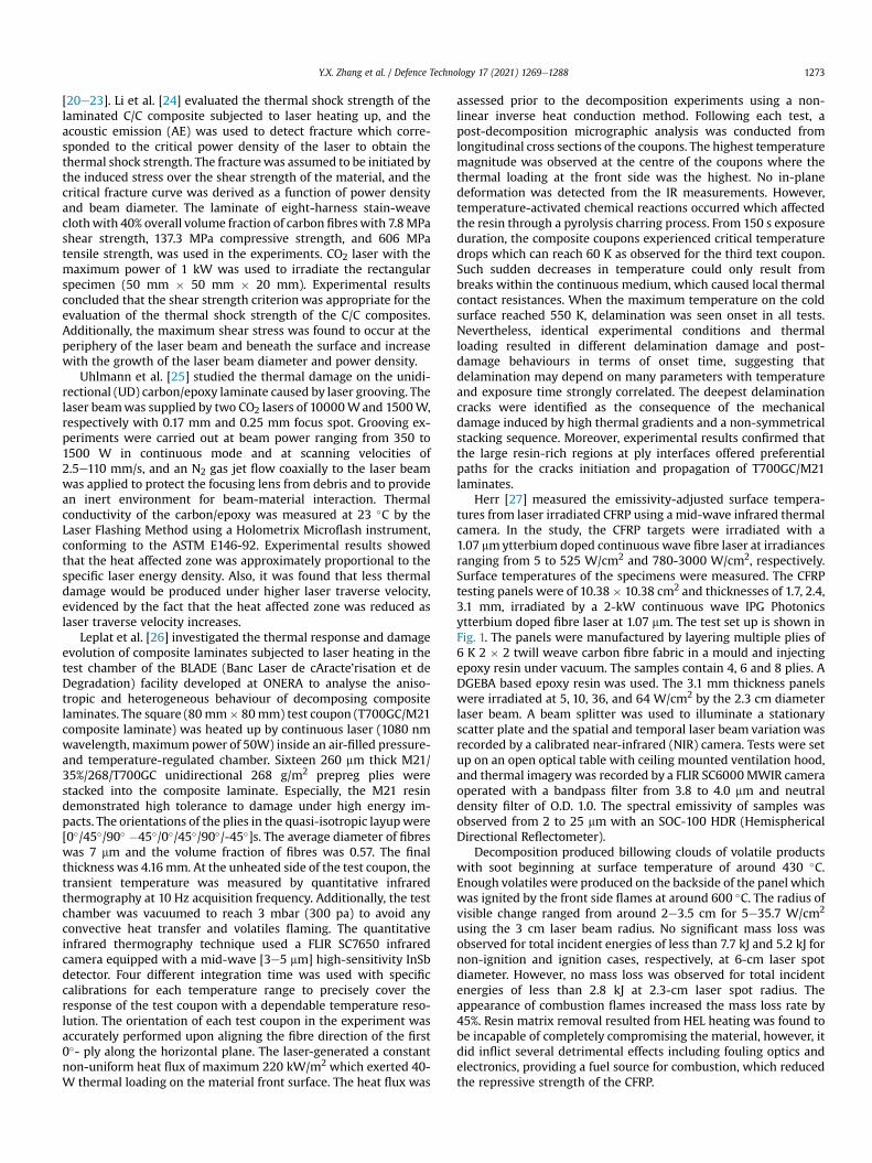
Herr [27] measured the emissivity-adjusted surface tempera-tures from laser irradiated CFRP using a mid-wave infrared thermalcamera. In the study, the CFRP targets were irradiated with a1.07 mmytterbium doped continuous wave fibre laser at irradiancesranging from 5 to 525 W/cm2 and 780-3000 W/cm2, respectively.Surface temperatures of the specimens were measured. The CFRPtesting panels were of 10.38� 10.38 cm2 and thicknesses of 1.7, 2.4,3.1 mm, irradiated by a 2-kW continuous wave IPG Photonicsytterbium doped fibre laser at 1.07 mm. The test set up is shown inFig. 1. The panels were manufactured by layering multiple plies of6 K 2 � 2 twill weave carbon fibre fabric in a mould and injectingepoxy resin under vacuum. The samples contain 4, 6 and 8 plies. ADGEBA based epoxy resin was used. The 3.1 mm thickness panelswere irradiated at 5, 10, 36, and 64 W/cm2 by the 2.3 cm diameterlaser beam. A beam splitter was used to illuminate a stationaryscatter plate and the spatial and temporal laser beam variation wasrecorded by a calibrated near-infrared (NIR) camera. Tests were setup on an open optical table with ceiling mounted ventilation hood,and thermal imagery was recorded by a FLIR SC6000MWIR cameraoperated with a bandpass filter from 3.8 to 4.0 mm and neutraldensity filter of O.D. 1.0. The spectral emissivity of samples wasobserved from 2 to 25 mm with an SOC-100 HDR (HemisphericalDirectional Reflectometer).
Decomposition produced billowing clouds of volatile productswith soot beginning at surface temperature of around 430 �C.Enough volatiles were produced on the backside of the panel whichwas ignited by the front side flames at around 600 �C. The radius ofvisible change ranged from around 2e3.5 cm for 5e35.7 W/cm2
using the 3 cm laser beam radius. No significant mass loss wasobserved for total incident energies of less than 7.7 kJ and 5.2 kJ fornon-ignition and ignition cases, respectively, at 6-cm laser spotdiameter. However, no mass loss was observed for total incidentenergies of less than 2.8 kJ at 2.3-cm laser spot radius. Theappearance of combustion flames increased the mass loss rate by45%. Resin matrix removal resulted from HEL heating was found tobe incapable of completely compromising the material, however, itdid inflict several detrimental effects including fouling optics andelectronics, providing a fuel source for combustion, which reducedthe repressive strength of the CFRP.
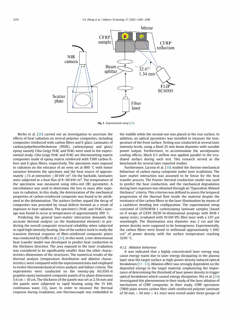
Fig. 1. Experimental setup [27].
Y.X. Zhang et al. / Defence Technology 17 (2021) 1269e12881274
Berlin et al. [28] carried out an investigation to ascertain theeffects of heat radiation on several polymer composites, includingcomposites reinforced with carbon fibres and E-glass. Laminates ofcarbon/polyetheretherketone (PEEK), carbon/epoxy and glass/epoxy namely Ciba Geigy 914C and 914G were used in the experi-mental study. Ciba Geigy 914C and 914G are thermosetting matrixcomposites made of epoxy matrix reinforced with T300 carbon fi-bres and E-glass fibres, respectively. The specimens were exposedto radiation on the entrance of an oven set at 800 �C with minorvariation between the specimen and the heat source of approxi-mately �1% at intensities �30 kW∙m2. On the backside, laminateswere subjected to a heat flux of 8e60 kW,m2. The temperature ofthe specimens was measured using infra-red (IR) pyrometer. Amicrobalance was used to determine the loss in mass after expo-sure to radiation. In this study, the deterioration of the mechanicalproperties of carbon-reinforced composite was found to be attrib-uted to the delamination. The authors further argued the decay ofcomposites was preceded by visual defects formed as a result ofexposure to heat radiation. The specimen’s (914C and 914G) dam-age was found to occur at temperature of approximately 300 �C.
Predicting the general laser-matter interaction demands theaccurate thermal analysis (as the fundamental element) in pre-dicting the overall composite structural reliability when subjectedto rapid high intensity heating. One of the earliest work to study thetransient thermal response of fibre-reinforced composite plateswas conducted by Griffis et al. [29]. In this work, a one-dimensionalheat transfer model was developed to predict heat conduction inthe thickness direction. The area exposed to the laser irradiationwas considered to be significantly smaller than the other charac-teristics dimensions of the structures. The numerical results of thethermal analysis (temperature distribution and ablative charac-teristics) were compared with the experimental data and employedto evolve thermomechanical stress analysis and failure criteria. Theexperiments were conducted on the twenty-ply AS/3501-6graphite epoxy laminated composite panels of in-plane dimensions5.6 cm� 10 cm. The thickness of the panels was set as 2.54 mm andthe panels were subjected to rapid heating using the 15 kW,continuous wave, CO2 laser. In order to measure the thermalresponse during irradiation, one thermocouple was embedded in
the middle while the second one was placed at the rear surface. Inaddition, an optical pyrometer was installed to measure the tem-perature of the front surface. Testing was conducted at several laserintensity levels, using a fixed 25 mm beam diameter with variablepower output. Furthermore, to accommodate the aerodynamiccooling effects, Mach 0.3 airflow was applied parallel to the irra-diated surface during each test. This research served as thebenchmark for several later reported studies.
Furthermore, Lacroix et al. [30] studied the thermo-mechanicalbehaviour of carbon epoxy composite under laser irradiation. Thelaser matter interaction was assumed to be linear for the heattransfer process. The Fourier thermal conduction model was usedto predict the heat conduction, and the mechanical degradationduring laser exposurewas obtained through an “Equivalent Ablatedthickness” criteria. This criterionwas defined to assess the temporalprogression of the thermal flow inside the material despite theresistance of the carbon fibres to the laser illumination by means ofa cantilever bending test configuration. The experimental setupconsisted of G939/M18-1 carbon/epoxy laminate samples (basedon 8 wraps of G939 50/50 bi-dimensional prepregs with M18-1epoxy resin), irradiated with 10 kW IPG fibre laser with a 1.07 mmwavelength. The illumination area diameter was 2 cm and thepower density were supposed to be homogenous. Experimentally,the carbon fibres were found to withstand approximately 1 kW/cm2 of power density with the surface temperature reaching3250 �C.
4.1.2. Ablation behaviourIt was indicated that a highly concentrated laser energy may
cause energy waste due to laser energy dissipating in the plasmalayer near the target surface as high-power density induced opticalbreakdown [31e33]. Ablation effect was strongly dependent on thedeposited energy in the target material, emphasizing the impor-tance of determining the threshold of laser power density to triggeroptical breakdown which caused energy dissipation. Wu et al. [34]investigated this phenomenon in their study of the laser ablation ofmechanism of CFRP composite. In their study, CFRP specimens(T800 plain woven carbon fibre cloth reinforced polymer laminateof 50 mm � 50 mm � 4.1 mm) were tested under three groups of

Y.X. Zhang et al. / Defence Technology 17 (2021) 1269e1288 1275
laser irradiation to obtain ablation behaviours and morphologies ofthe CFRP. The power density for continuous wave laser, long pulsedlaser (200 ns pulse duration), and short pulsed laser (10 ns pulseduration) was 3.54 � 106 W/m2, 1.50 � 1012 W/m2, and3.00 � 1013 W/m2 respectively. All lasers were designed to irradiatethe square CFRP specimens for 10 s with random polarizations. Thesurface morphologies were photographed by optical microscopeand then compared to the CAD drawing. Under continuous laserirradiation, the CFRP specimen was ablated by several layers fol-lowed by voids appearing throughout the epoxy layer after 10 s. Theablation effects on the under-epoxy laminate closely attached tothe top carbon fabric were reduced because laser-induced plasmaabsorbed a large part of the incident laser energy as air breakdownoccurred after the surface carbon fibre fabric locally evaporated.However, long pulsed wave laser drilled a conical hole through thelaminate with largest radius around 1 mmwhich was smaller thanthe laser beam radius, as compared to that the short-pulsed laseronly ablated the thin surface carbon fabric of CFRP.
Zhu et al. [35] studied the ablation behaviour T300/AG80 carbonfibre reinforced laminate following layup sequence [±45�/0�/90�/0�]S of a shape of 200 mm � 200 mm � 1.5 mm, under Nd:YAGgenerated laser beamwith 1064 nmwavelength for 5 s irradiation.The laser power density was 50 W/cm2, and the laser beam radiuswas 10 mm, 20 mm, and 30 mm respectively. They used a CRONOS-PL2-DIO dynamic strain meter to measure the specimen response.At 0�, 45�, and 90� directions at front and back surfaces of thespecimens, strain foils were attached. Experimental results showedthat the larger the laser beam radius, the greater the thermal shockexerted upon the specimens. The maximum shocking tensile strainrecorded in 20 mm and 30 mm laser beam radius cases are 5.7 and8.4 times the maximum shocking tensile strain in the 10 mm case,respectively. Generally, the strain value at different locations withinthe laser spot decreased as it was farther from the centre of thespot.
Stratoudaki et al. [36] investigated the effect of laser generatedultrasound on epoxy resins using three different lasers, i.e., TEA CO2(Coherent, Hull, Laserbrand150), Q-swtiched fundamental Nd:YAG(Spectron Laser Systems), and XeCl excimer (Lamda Physik). AMichelson interferometer was used to directly measure the ultra-sonic waveforms and record the absolute epicentral displacementson the opposite side of the sample, and the samples were inspectedunder optical microscope. The generation beam spot size was keptbetween 0.02 and 0.03 cm2 throughout the experiment. The carbonfibre reinforced composite (CFRC) had a thin superficial layer ofresin with a mean thickness of ~12 mm. Pure epoxy resin sampleswere prepared using resins commonly used for the manufacture ofcomposites, of which the first was a cold-curing epoxy resin, andthe second a warm-curing epoxy resin. The Nd:YAG operated inTEM00 mode with pulse duration at FWHM was 10 ns and its spotsize was ~0.02 cm2. The FWHM of the TEA CO2 was 50 ns, and thespot size was ~0.03 cm2. The excimer laser had a ‘top hat’ beamprofile, and its FWHM was 40 ns and its spot size was ~0.02 cm2.Results showed that in the case of the Nd:YAG laser, most of theenergy was absorbed in the first layer of carbon fibres. In the case ofthe excimer laser, the ablation threshold was found to be very lowbut the damage was localized at the superficial resin layer. Noexposure of fibres was observed in all three cases.
Pan et al. [37] investigated the ablation mechanism and the ef-fects of laser parameters in laser ablation of carbon fibre reinforcedsilicon composites. The researchers used six different laser powerdensities and six levels of pulse numbers. Results revealed thatdamage to surface morphology included three areas: the boardregion, the transition region, and the centre region. As the laserpower density increased, the ablation at the centre regionincreased significantly with the surface cracking with spherical
composite particles observed in the transition region. The surfacemorphology of the composite showed that the degradation causedby laser irradiation at different power densities ranged from4.77 � 102 W/cm2 to 12.1 � 102 W/cm2. An increase in the laserenergy contributed to ablation of the surface coating because of thehigh temperature at the centre of the lase spot. In addition, thecomposite matrix was decomposed when exposed to strong laserresulting in the exposure of the non-ablated carbon fibre layers. Thedamage to the composite was resulted from the high laser tem-perature which reached the decomposition temperature of thecomposite material, although it did not reach the melting point ofthe composites. As a result, the compositewas ablatedwhile carbonfibres were retained but exposed on the surface of the sample. Theablation centre showed large spherical particles at the ablationcentre which was an oxidation product of the composite material. Ahigh number of large spherical materials were also found to bedistributed at the ablation edge of the composite coating. As thelaser power on the composite material increased, the boundarybetween non-irradiated region and the irradiated region becameclearly visible. Both the carbon fibre and composite matrix surfacewere ablated. In addition to complete sublimation of the first layersof the composite and the matrix, the carbon fibres were also sub-limated. The sublimation temperatures of the silicon carbide andcarbon composite were 2700 �C and 3550 �C, respectively, and thelaser temperature at the centre of the composite material wasabove 3550 �C.
4.1.3. Interlaminar effectsWu et al. [38] conducted a comprehensive study on the me-
chanical and thermal properties of glass fibre reinforced epoxycomposites. The diglycidyl ether of bisphenol F epoxy resinwith theepoxy equivalent weight of 164e172 g/mol was used. The curingagent was diethyl toluene diamine (DETD, HY5200, HuntsmanAdvanced Materials) with an amine weight equivalence of 44.5 g/mol. The boron free glass fibre cloth was treated by silane couplingagent. The fabric was 0.2 ± 0.022 mm thick with count of 18 ± 1threads/cm in the warp and 14 ± 1 threads/cm in the fill. Theprepared composite panel was cut into specimens for the shortbeam shear test with the dimensions of 24 mm � 8 mm � 4 mm.60Co g-ray with dose rate of 300 Gy/min at ambient temperaturewas applied upon the specimens. The total doses of 1 MGy, 5 MGyand 10 MGy were applied respectively. Through the short-beamshear (SBS) test according to the ASTM D2344, the apparentinterlaminar shear strength (ILSS) was determined. The specimenswere dipped inside a cryostat filled with liquid nitrogen to achievecryogenic condition. After the SBS tests, a Hitachi S-4300 SEM wasadopted to observe the fracture surfaces of the specimens. TheUVeVis spectra of the specimens were measured by a Cary 5000spectrometer. Fourier transform infrared spectroscopy was per-formed on an Excalibur 3100 spectrometer. Distinct failure due tothe interlaminar shear was found in all cases. No clear effect of thegamma ray irradiation on the interlaminar shear strength wasfound when the total doses was less than 5 MGy. However, the ILSSsharply decreased after exposed to the total 10 MGy dose. Tworadiation-induced processes, i.e., the molecular chain scission andcrosslinking, were identified to associate with ILSS reductionmechanisms. Specifically, the chain scission generally reduced thecryogenic strength and stiffness of the matrix which resulted in thedegradation of the ILSS. After 10 MGy irradiation, the ILSS wasfound being decreased by around 58%. Thermogravimetric analysisshowed that the initial degradation temperature (IDT) of thespecimens decreased drastically after the irradiation with adecrease of 18% and 25% in IDT respectively from 5 MGy to 10 MGycompared to that of the non-irradiated specimen. Overall, thecomposite laminate could resist the dose of 5.0 MGy.
Y.X. Zhang et al. / Defence Technology 17 (2021) 1269e12881276
Following the work done by Wu et al. [34], Liu et al. [39,40]further investigated the CFRP composite laminate interacting withinfrared wave laser, and interlaminar damage of CFRP laminateunder continuous laser irradiation. The 2 mm thick CFRP laminasynthesized from CCF-700 carbon fibre and BA9916-II resin matrixwas autoclave treated and then being irradiated by infrared laser of1064 nmwavelength and 200 ns pulse duration repeating at 10 Hz.The specimen was compacted by 16 laminates of a thickness of0.125 mm by [45�,0�,-45�,90�]2s sequence, and then shaped into50 mm � 50 mm � 50 mm cube with 145±g/m3. The specimenwasirradiated by the infrared laser of 1064 nm wavelength by pulseduration of 200 ns repeating at 10 Hz. The laser spot radius was1.1 mm and the output power were around 1.1 J. Optical microscopewas used to observe cut cross sections of the CFRP specimens. Itwas observed that the longer irradiation would cause wider hole atthe back surface of the specimens after it was penetrated andaround 10 s were required to drill the specimen through. In addi-tion, Finite Element model was utilized to investigate the temper-ature and phase change of the specimens. A wider hole than thatfrom the experiment as well as a coarse aperture wall were pre-dicted from the numerical simulations.
When being exposed to high temperature, CFRP laminatesbecame very susceptible to deterioration in mechanical properties,and composite gradients are prone to flaming [41,42], and inter-laminar thermal damages induced by ablation could lead todisastrous consequence on CFRP laminate. In theory, it was thepropagation of the interlaminar cracks that governs the interlam-inar separation of the CFRP and was greatly dependent on the fibrelay angles. However, the multi-interlaminar shear failure modewasbasically attributing to the weak fibre-matrix interface in the CFRP.In the work done by Liu et al. [40], the interlaminar damage mor-phologies of the CFRP laminate under continuous laser irradiationwas recorded. Acquired interlaminar damage pattern and its spatialdistribution were further analysed. An optical microscope and ascanning electron microscope (SEM) were used in the study. Thesame specimen in the previous study [39] was used again but wasirradiated vertically by continuous wave laser in a cabinet filled ofNitrogen. The continuous wave laser of 1070 nm wavelength wasused to irradiate the specimens for 3 s by output of 500 W, 800 Wand 1000 W respectively. The optical microscope and SEM wereused to observe the interface damages at cross section of thespecimens. Morphologies at cross section were recorded, illus-trating pyrolysis occurring in up to eight laminate from the surfacelayer where fibre fracturing under direct irradiation. Similar to thephenomenon observed in carbon/carbon composite exposed toelevated temperature [43], the interlaminar cracks were found toincrease in width and length as laser power output rise, and ataround the backward surface large interlaminar cracks were seen.
4.1.4. Damage analysisGay et al. [44] studied the local tensile stress caused by laser-
induced shock within CFRP composite laminates involved in aero-nautic and defence industry. They selected the carbon fibres G40-800-24 K reinforced epoxy Cytec® 5276-1 with 4 and 8 ply lami-nates by layup sequence [0�/90�]S and [0�/-45�/90�/45�]S respec-tively as test specimenwhich were shaped to 15 mm� 15 mmwitha thickness of 600 mm and 1200 mm respectively. The averagediameter of the carbon fibres is 5 mm and their volume fraction is70%. A linear-elastic law [45,46] was used to describe the dynamicbehaviour of the composites. In their adhesion test, the load wasgenerated by a Nd:YAG laser which delivered a calibrated pulsewith a duration of 9.3 ns at Full Width at Half Maximum (FWHM)and an energy of 1.5 J with 532 nm wavelength. The high intensitypulse drove a compression wave within the specimen to test andwas eventually released to relax the material to its initial state. The
pulse propagating through the sample thickness to the oppositesurface where it bounced back in tension could induce damage.Firstly, the experiments were performed on the 4-ply lamina and adelamination threshold for an incident intensity of [0.9e1.03] GW/cm2 was detected. Secondly, the 8-ply lamina was tested underirradiation of 450 ns pulse duration laser, and the 1.49 GW/cm2
laser intensity was found to be strong enough to induce delami-nation. The microtomography X-Tek HMXST 225 was used toexamine recovered samples. The incident intensity to inducedelamination in the 8-ply case was found higher than that in the 4-ply case, and it was observed that laser-induced stress waves couldproduce on-axis tension which caused delamination of the speci-mens. The tensile strength of both the 4 and 8 ply laminawas foundto be around 292 MPa, which was in the same range as the strengthevaluated by Yu and Gupta [47], and Riedel et al. [48].
Laser shock wave techniques have also been used to experi-mentally examine the damage of directed energy on compositeswhich are widely used in the aerospace industry. Ecault et al.[49e51] first examined how laser shock wave impacted on carbonfibre reinforced polymer (material T800/M21). The T800/M21 is acommon composite material in the aeronautical industry, madefrom mon-conventional matrix that is mixed from thermoplasticnodules and thermoset epoxy resin whose mechanical character-istics are created to improve shock resistance. Besides theiradequate mechanical properties, T800/M21 composite materialsare also used in the aeronautics industry because of their lightweight. Characterization of T800/M21 materials for various defectshas been achieved in the past using Interferometric Confocal Mi-croscopy, X-ray Radiography, and Optical Microscopy. Ecault et al.used Carbon Fibre Reinforced Polymer (CFRP) samples for theexperiment to assess how laser shock waves impacted on com-posite materials. The researchers first conditioned the samples byshocking them with various laser energy levels to generate diverselevels of internal damage. The samples were then recovered fromthe set-up for analysis using several diagnostic setups. The firstshocks were performed on thin T800/M21 samples measuring1.5 mm that were extracted by cutting out from thicker materials.Optical micrography was used to analyse the samples which wereexposed to laser shock waves. The analysis was used to assess thecorrelation between laser intensity and damage characteristics onthe composite material. The second shock waves were done onthicker materials of 6 mm as shown. Resulting damage was ana-lysed using Interferometric Confocal Microscopy (ICM) and X-rayradiography on the back face of the samples. The obtained data wasused to assess the damage threshold done on the T800/M21 CFRPbecause of laser shock dynamic loading. Results from the 1.5 mmT800/M21 composite samples revealed that the damage induced bylaser shock was cone shaped through the sample thickness. Thecone basis was situated at the back of the face.
For the different laser shocks, the sample exhibited a similarkind of damage despite the laser strength used. Ecault et al. [49e51]also performed laser shocks on 66 mm thick T800/M21 CFRPsamples. Like the thin samples, four different laser pulse intensitieswere used. Results showed that since the samples were thick, thelaser did not spall them. The laser shock wave amplitude wasdecayed through the material’s thickness as there was a longerdistance to close before emerging from the other side of the face.The resulting damage was evident in the form of small blisters onthe material back face based on the ICM and X-ray radiographymeasurements. In summation, it was observed that the damageresulting from the laser shock wave propagation on compositematerials was resulted from laser intensity. A potential damagescenario for the T800/M21 composite due to high laser irradiationwas shown revealing the damage tolerance of aircraft compositematerials when exposed to high energy laser wave shocks.
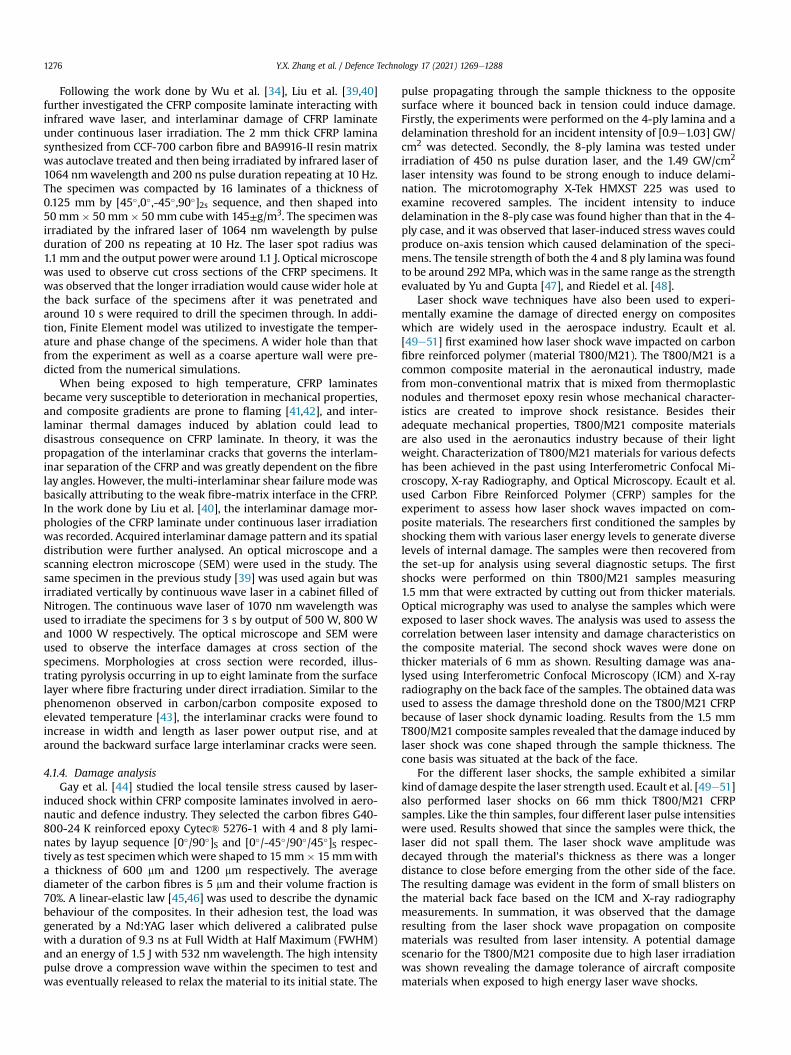
Fig. 2. Experimental setup from top view [52].
Y.X. Zhang et al. / Defence Technology 17 (2021) 1269e1288 1277
Ecault et al. [49e51] then examined composite material damageresulting from laser-induced shockwaves on 10mm long and 5mmthick transparent epoxy composites using optical shadowgraphy.The shock waves from high laser intensity were focused on com-posite material for 3 ns pulse duration (1.2e3.4 TW/cm) generatinga pressure of between 44 GPa and 98.9 GPa. Results revealed thatthe shock wave and release wave generated by the laser reverber-ation at the back face was followed by a dark zone. The resultsindicated that the shock wave and release wave resulting in darkzone at the back face corresponded with the creation of tensilezone due to crossing on the loading axis of the release waves thatcame from the edge of the impact region. The shockwave setting upat t ¼ 0.5 ms and propagation t ¼ 1 ms and 1.5 ms revealed two mainshapes. At t ¼ 1 ms there were thin curved black lines which werethe shock wave. At this stage, the composite was compressedbecause of the pressure state that contributed to the observeddarkness. Considering that the shock was short, the pressure wasreleased once the loading stopped. The shockwavewas followed bya grey area which was a colour that was evident in unloaded areas.A sizeable black blur behind the first two waves was identifiedwhich traduced a tensile loading due to the geometry of the laserimpact. The phenomenon was called the edge effect which reliedon the principle of spherically propagating release waves inside thecomposite from the edge of the impacted area. Upon reaching thefree surface, the shock waves were reflected releasing a curved greyline, which propagated backwards from right to left and crossed theblack blur which was the incident tensile stressed region. The backface was progressively loaded with tensile stress in line with thespallation phenomena and shock wave propagation. Ecault et al.[49e51] also investigated the impact of laser shocks on eco-composites to assess how the materials degraded under laserimpact loading. The researchers compared the impact of laser shockinduced damage based on back observations of composite samplesfor various types of eco-composites. Inside delamination, residualblister and spallation resulting from laser impact on fibre lengthwere also tested using the Terahertz technique. The laser wasfocused on the surface of the specimen. Aluminium coating causedthe matter/laser interaction to be generated on the sample surface,which caused the high-pressure plasma created from the process toexpand rapidly. Reactions inside the material contributed to ageneration of shock waves. The directed shock propagated throughthe composite material depending on the geometry and charac-teristics of the samples. Due to impedance mismatch, the incidentshock wave was reflected into the release wave upon reaching thesample blackface creating a release backward wave propagation.The release wave crossed the incident release wave which camefrom initiation at the end of the loading (returns to the initial state).The crossing of two release waves contributed to high tensile stresswhich could damage the composite material if the threshold wasexceeded. In composites with short fibres such as TWA and WA,damage resulted from ejection and separation of fragments fromthe surface, which was referred to as the spallation phenomenon.For the WA and TWA composites, the spallation phenomenon wasnoted to have variations in its damaging ability where the area ofdamage for the TWA was 6.6 mm compared to 4.7 mm damagerecorded in WA composite under the same laser shock. These ob-servations demonstrated that thermal treatment of spruce fibrescaused high damage due to brittleness of the composite materialwhen exposed to high energy laser. When considering the com-posites with flat mat reinforcement, no spallation was recorded. Inthis case, the inside damage resulting from laser shock generatedresidual relief which caused small blisters on the back-face surfaceof the FBB and FPLA composites. The measurement of diameters ofblisters resulting from laser directed shocks on the compositesshowed that there were also differences in behaviours. The FPP
sample had a blister diameter of 8.5 mm compared to the blisterdiameter of 10 mm on the FPLA sample. Thus, laser shock createdmore damage to FPLA samples than to the FPP samples. Finally, theHE composites showed partial blister spallation with a diameter of9.4 mm, while that of the GE composite had a whitened zone of7.7 mm. It was found that composites which were used in theaerospace industry exhibited different behaviours when beingexposed to laser impact loading and directed energy sources,largely depending on distribution, length, type of fibres, and thematrix used for composite materials. When the same laser impactintensity was used, the compositematerials recorded three types ofdamage at the back-face samples. These damages included insidedelamination, residual blister, and spallation. Short fibres weredamaged from the spallation phenomenon which indicated theirlow strength. Non-woven fibres indicated residual blisters whichwas a composite damage step preceded spallation. In contrast,woven fibres showed combined spallation and blister damage, butwoven glass composites showed whitening on back face surface.
Garcia et al. [52] investigated the possibility of lasers defeatingtargets without penetration but with heat re-radiating to internalcomponents by using a thin carbon fibre-reinforced polymer (CFRP)and a steel disc to represent target skin and internal component,respectively. A FLIR® A325sc infrared camera was used to measuresteel disc temperature. Thin carbon fibre composite laminate con-sisting of 2-, 4-, and 6-ply sheets and having 50% carbon fibre-resinmass ratio were shaped into 5.08 cm � 25.4 cm strip specimens.The composites were reinforced with a 3K plain-weave, 5.7 oz/yd2
carbon fibre cloth. After being vacuum bagged for 1 h at 1 atmpressure, the composites were further heated to 121 �C and curedusing a 2-ton press for 1.5 h. A YLR-100-AC fibre laser served tooutput laser beamwith a M2 value of 1.07, maximum 100W, and 5-mm diameter. The actual range of on-target irradiances was be-tween 101.9W/cm2 and 509.3 W/cm2 due to lab limitations. A 1 cmdiameter metal disc made from 1008 carbon steel with a nominalthickness of 0.15 mmwas used to simulate the internal component.Its temperature was measured by an attached Type K thermo-couple. In the experimental setup, an IR camerawas offset 53� fromthe plane perpendicular to the sample plate to avoid any damage aslaser could potentially penetrate the composite. The setup of theexperiment is shown in Fig. 2. High energy laser was placedperpendicular to the sample plate at other side. The specimenswere subjected to five different irradiances of between 152.8 W/
Y.X. Zhang et al. / Defence Technology 17 (2021) 1269e12881278
cm2 and 356.5 W/cm2. The resulting temperature was measured atthe back of the composite. Results confirmed that without com-plete penetration, the intense local heating caused by laser radia-tion on a CFRP laminate can damage the internal components.Radiation from the heated internal component in turn contributedto the development of flames at the back surface of the CFRP. Thereleased heat elevated the temperature of the 6-ply CFRP backsurface by 237 K during the 305.6 W/cm2 test and by 240 K duringthe 356.6 W/cm2 test. In a typical unmanned aerial vehicle (UAV)fuselage, the heat gave rise to internal flames that could damageflight control systems and ignite the fuel mechanism.
In the study conducted by Voisey et al. [53], SEM and Ramanspectroscopy were used to investigate the effects of the fibre typeon the extent of laser-induced fibre swelling in carbon fibre com-posites being laser-drilled by pulsed Nd:YAG laser (l ¼ 1.06 mm).T300, high modulus (HM) and P100 fibres were heat treated for12 h at 2000 �C prior to the experiment. An average output powerof 135 W, M2 value of ~25 with single pulsed of energy 1.0 J andduration 1.0 ms Nd:YAG laser was adopted. An average powerdensity of around 30 kW/mm2 was yielded by the 100 mm focusedspot diameters. Prior heat treatment was found to have substan-tially reduced the swelling exhibited by the T300 fibres but hadlittle effect on other two fibres. The obtained spectra showed laserdrilling had rendered the T300 fibres more graphitic and lessdisordered. It was proposed that the rapid heating and high ther-mal gradients generated by laser drilling tended to volatilise non-carbon impurities and create high gas pressures. These high pres-sures could act as a driving force for the new structure to be moreopen which was apparently retained after the impurities weredriven off. This mechanism explained why fibres containing largerquantities of residual (volatile) impurities were more prone tolaser-induced swelling.
Instead of the total failure/destruction of the targeted structure,the recent military interest has been shifted to tactical threats, suchas cruise missiles and unmanned aerial vehicles (UAVs), which canbe countered with comparatively lower laser irradiance. The idea isto bring the incident laser wavelength to the near Infrared region,which can penetrate the matrix resin of most of the compositematerials. One such study was conducted byWu et al. [54] inwhichit was argued that the weakly absorbed, more deeply penetratingnear-IR radiation softened the resin matrix resulting in structuralfailure under load at lower laser intensity than what was requiredfor mid-IR lasers. The study used two materials for illustration, i.e.translucent fibreglass composite and opaque carbon composite.Since the study was related to the deep penetration of the laser, thefirst step in the experimental program was to determine the ab-sorption properties in material samples, so that the comparison ofthe results with the theoretical values could be made. Followingthis, the measure of the compressive load strength under near-IRlaser irradiation was made. The composite plate samples wereheld vertically in a hydraulic load machine designed to apply aconstant compressive force. A uniform illumination on the sampleswas achieved by passing light from a 1.5 kW diode laser array andthe wavelength of 0.8 mm through a lens duct and imaging lenses.Digital and IR cameras were used for recording purposes. The ex-hausts were provided for the fumes to be exhausted. The researchdiscovered that the volume heating by direct in-depth absorptionof laser energy in case of translucent fibreglass composite materialand rapid conduction of surface-deposited energy as in the case ofopaque carbon composite may cause the failure at one to threeorders of magnitude lower than the intensity required to produce alethal effect by target penetration.
The intense heating produced by the laser system can adverselyaffect the mechanical properties of the composite structures suchas the tensile/shear strength and elastic modulus. Meanwhile,
severe thermal irradiation may also induce significant geometricalchanges in the structure’s surface ablation or localized burnthrough. It was well understood that if the surface temperaturereached the ablation temperature of the composite, the materialwould undergo a sublimation reaction. The burn-out materialreduced the structural stiffness of the remaining laminate andincreased the mechanical stresses, thus degrading the structure’sload-carrying capability. Moreover, due to the presence of highlynon-uniform temperatures over the thickness of the compositelaminate, thermal in-plane forces and bending moments mightarise. Obviously, these thermal loads play an important role in thechange of constitutive relations of a laminate, initially subjected tomechanical loads. Hence, methods for predicting composite dam-age under coupled laser irradiation and mechanical loading havebeen developed by the researchers [55,56,61].
Candan et al. [57] investigated laser threats on fibre-based bal-listic-resistant composites, and the Spectra Shield SR-3136 com-posite material was used in the investigation. Spectra Shield SR-3136 was a thermoplastic composite made of ultra-high molecu-lar weight polyethylene (UHMW-PE) fibres reinforced with low-density (LD-PE) fibres. The composite was exposed to a contin-uous wave laser beam at 915 nm of a fibre-coupled diode lasermodule. The specimen exposed to the laser beam had a puncturewith significant swelling around the entry hole subjected to tem-perature of 450 �C or more. A full penetration was observed at alaser energy of 20 kJ and greater. Furthermore, as a result of theslight tapering induced by asymmetric behaviour close to theentrance, the entry hole had a diameter of 16 mmwhich was largerthan the diameter of the exit hole of 2.4 mm.
4.2. Combined loading
Allheily et al. [58] investigated the thermo-mechanical behav-iour of aeronautic materials (CFRP) subjected to powerful electro-magnetic fluxes to assess the likely impact of directed energysystems on aircraft composite structures. The method proposedwas meant to find a way to neutralise unmanned aerial vehiclesthat posed threat to defence installations. In the preliminary studythe authors carried out three tests namely thermal surface char-acterization, thermal in-depth characterization, and thermo-mechanical characterization on G939/M18-1 specimens (HexcelComposites) made of plain-woven carbon fabrics. In all the tests thespecimens were initially exposed to a homogenous irradiationwitha 10 kW fibre laser from IPG. Approximately 3% of the laser energywas produced with a beam splitter. Concurrently, the front side ofthe specimenwas exposed to gas flowwhichwas applied parallel tothe irradiated surface before, during and after the irradiation. Thepurpose of gas flow was to assess the carbon fibres combustionimpact on temperature readings by comparing experiments withair or nitrogen. After each experiment the specimens wereweighedto determine mass loss based on laser intensity and the irradiationtime.
Results show that with growing laser power the temperature ofthe irradiated zone increased and reached a maximum value of3300 �C for power densities that were greater than 1000 W/cm2.The maximum power recorded aligned with the values recorded byother researchers [49e51], and it referred to the sublimationtemperature of the carbon composite fibres. When observing postirradiation samples, the same property was also observed whileirradiations with power density of less than 1000 W/cm2 onlyimpact on epoxy matrix because the sublimation temperature waslower than that of the carbon material where drilling becamevisible when the composite sample were irradiated using laserpower density that was greater than the threshold value. Theevolution of the temperature gradient was evident inside the
Y.X. Zhang et al. / Defence Technology 17 (2021) 1269e1288 1279
composites where the results revealed that CFRP was a goodthermal insulator since it could take some seconds before the back-face side temperature became significant. The observed thermalresistance was attributed to strong carbon fibres which couldabsorb almost all laser energy in a single fabric layer and sustaininghigh temperatures without resulting in ablation. Once the carbonablation conditions were attained, the amount of laser energyneeded to damage the composite material was high because of thesubstantial carbon ablative enthalpy. All these observationsexplained for the 10 s continuous laser irradiation resulting in veryhigh temperatures at the composites’ front face (above 2000 �C for200 W/cm2), while the rear side that was 4 mm in thicknessreached only 250 �C. In contrast, the pyrolyzes process on thematrix started after irradiation. The side post-irradiation andinfrared observation revealed an exothermic pyrolysis at between300 �C and 350 �C that preceded the delamination front. Thechemical degradation temperature ranged in line with the thermo-gravimetric analysis resulting in pure resin component with aninert ambient medium. The composite recorded thickness reduc-tion during irradiation and post-irradiation since the bendingdisplacement increased even when the irradiation stopped. Thestudy indicated a good thermal insulation of the composite mate-rial, which was largely because of the potential of carbon fibres toabsorb and support heat fluxes. Furthermore, the delamination ofthe composite reduced energy deposition on the specimen.
Zhao et al. [59] conducted an experimental study on the failurebehaviour of CFRP composites subjected to tensile loadings underthermal environments and laser irradiation. T700/BA9916 epoxyprepreg was cured at 180 �C, and the ply pattern was [45�/0�/-45�/90�]2s. The epoxy and fibres accounted for 0.467 and 0.533respectively in the laminated composites which had a thickness of2.40 mm and width of 20 mm. Electric resistance wire was woundinto a heating band, being set around the specimen to conduct thetensile tests at thermal environments. Thermal couples of NiCr-NiSitype were installed to monitor the specimen temperature andheating rate, and tensile strain was acquired by a DIC system. TheCFRP specimens were irradiated by continuous wave laser by po-wer densities ranging from 1.5 MW/m2 to 12.7 MW/m2 in a nitro-gen protection environment for the sake of avoiding possiblecombustion. The laser source was a YLS 1070 nm fibre laser of 2 kWprovided by IPG Ltd. The defective specimen was further appliedwith tensile loading at 2 mm/min rate in MTS until failure. Resultsshowed that complex thermal damages could happen once CFRPcomposites were exposed to thermal loadings which could lead todecrease of the Young’s modulus and failure strength. Residualstrength was found to decline as target temperature or laser powerdensity increased. Besides, residual strength was found fallingdrastically before laser power density reached 6.3 MW/m2 afterwhich it decreased at a slower rate. However, a temperatureplateau zone was identified before 200 �C, which was the thermalpyrolysis activation temperature for epoxy resin. Sublimation (thephase transition of substance directly from solid to gas) of carbonfibres occurred once temperature reached 3000 �C. The turningpoint at which delamination cracks occurred was found to be at apower density of 2.5 MW/m2.
The failure behaviour of the T700/603 carbon fibre/epoxycomposite laminates under pre-load compression or tension andlaser irradiation was tested to study the effect of main parametersincluding pre-stress ratio, laser power density as well as thethicknesses of the specimens on failure time [60] of140 mm � 10 mm specimens with various thickness consisting of0.15 mm thick ply. A Zwick/Roell-Z100 universal testing machinewas employed to apply pre-load of 35% or 50% of the average ul-timate compressive collapse stress and 50%, 65% or 80% of theaverage ultimate tensile fracture stress to the composite laminate
specimens. The laser spot was 15 mm in diameter perpendicularlyfocusing on the centre of the specimenwith 0.202, 0.492, 0.953 and1.935 kW/cm2 power intensity. Specimens with the same thicknesswere tested under the same pre-load and same irradiation laserintensity. Laser irradiation was kept on until material completelyfailed. CO2 CW laser systemwas used to generate laser with 10.6 mmwavelength. The failure time was defined as the time from the startof irradiation to the complete fracture of the specimens. Resultsshowed that the laser power intensity at 0.202 kW/cm2, pre-stressratio at 0.5 and thickness of specimen at 1.5 mm would causecomplete fracture after 9.90 s irradiation. On the contrary, thefailure time in the compression test is much shorter than that in thetension test. Additionally, the failure mechanism in tension testmainly included fibre drag break, while delamination and bucklingwere what caused failures in compression test. The failure time ofthe specimens with the same thickness will be shortened expo-nentially as laser power intensity increased. The relationship be-tween the specimen failure time and the main parameters undertension load combined with laser irradiation and under compres-sive load combined with laser irradiation are expressed in Eq. (1)and Eq. (2) respectively.
tT ¼ 6:4411� 36:7988sh� 5:1239sh2 þ 35:1316se�3:1464Is
� 28:4074he�3:1464Is þ 5:2739h2e�3:1464Is
(1)
tC ¼ 0:7076� 11:1656I � 0:3597þ 10:9637hI � 0:3597
� 2:1372h2I � 0:3597þ 22:7927rsI � 0:3597
� 22:5215rshI � 0:3597þ 4:7401rsh2I � 0:3597 (2)
where tT, tc are the specimen failure time under tensile load andcompressive load, respectively, h is the thickness of compositelaminated specimen, rs is the pre-stress ratio, I is the laser powerdensity.
Kibler et al. [61] conducted a series of experimental andanalytical studies on the response of graphite-epoxy composites tocontinuous-wave CO2 laser radiation. Tensile coupons of onegraphite-epoxy system (Narmco 5208/T300) and one aluminiumalloy (2024 (T81)) were exposed to laser irradiation. Three com-posite laminates, namely (0�/±45�)C, (/±45�/90�)2S, and (90�//±45�)2S with 12-ply of nominal thickness of 0.073 mm were used.In the low power laser experiments, the laser irradiations wereperformed with a model 41 Coheren Radiation Laboratory laserwith incident beam power of 200 W. A Mach 0.2 airflow wasmaintained parallel to the specimen surface. An iron-constantanthermocouple at various positions on the back surface of thespecimen was used to monitor the temperature. In the high-powerlaser experiments, a GTE Sylvania model 971 with incident beampower of 750 W was used for the first series of exposures, and aMach 0.1 airflow was maintained across the width of the specimensurface. The 10 Kilowatt ‘flat-top’ laser was used for the secondseries of exposures. It was determined that the aluminium wasmore susceptible than composites to damage at a high laser in-tensity, especially, both penetration time and strength retentionwere less for aluminium than for the composites. A strengthretention in terms of fracture mechanics-based predictions wasproposed for the partially penetrated and laser-damaged compos-ites. Moreover, specimens loaded in tension and irradiated to fail-ure were found to fracture at a slightly lower preload than thestrength retention of specimens irradiated but unloaded.
Laser-induced damage on mechanically loaded laminates inunmanned aircraft was explored with a view to predict thethermal-mechanical response of the heated panel irradiated by
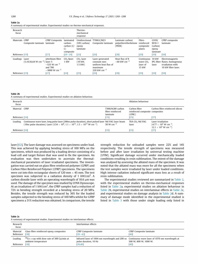
Table 2aA summary of experimental studies. Experimental studies on thermo-mechanical responses.
Researchfocus
Thermo-mechanicalresponse
Materials CFRPComposite laminate
CFRP Compositelaminate
laminatedcarbon-carbon (C/C)composite
Unidirectional(UD) carbon/epoxylaminate
T700GC/M21Composite laminate
Laminate carbon/polyetheretherketone(PEEK)
Fibre-reinforcedcompositeplates
G939/M18-1Carbon/epoxylaminate
CFRP compositelaminate
Reference [19] [27] [20e24] [25] [26] [28] [29] [30] [58]
Loadings Laser(5,10,56,64 W cm�2)
ytterbium fibrelaser 5e525 W cm�2
and 780e3000 W cm�2
CO2 laser1 kW
CO2 laser(10 kW,1.5 kW)
Laser-generatedconstant non-uniform heat flux ofmaximum220 kW cm�2
Heat flux of 8e60 kW cm�2
Continuouswave CO2
laser of15 kW
10 kWIPG fibrelaser
Electromagneticfluxes, homogenousirradiation with10 kW fibre laser.
Reference [19] [27] [24] [25] [26] [28] [29] [30] [58]
Table 2bA summary of experimental studies. Experimental studies on ablation behaviour.
Researchfocus
Ablation behaviour
Material CFRP T300/AG80 carbonfibre reinforcedlaminate
Carbon fibrereinforced composite(CFRC)
Carbon fibre reinforced siliconcomposites
Reference [34] [35] [25] [37]
Loading Continuous wave laser, long pulse laser (200ns pulse duration), short pulsed laser(10ns pulse duration). Laser (3.54 � 106, 1.1 � 1012, 1.5 � 1012 W cm�2)
Nd:YAG laser beam50 W cm�2
TEA CO2 Nd:YAGlaser
Laser irradiation(4.77 � 102 W cm�2,12.1 � 102 W cm�2)
Reference [34] [35] [25] [37]
Y.X. Zhang et al. / Defence Technology 17 (2021) 1269e12881280
laser [62]. The laser damagewas assessed on specimens under load.This was achieved by applying bending stress of 100 MPa on thespecimens, which was produced by a loading device consisting of aload cell and target fixture that was used to fix the specimen. Anevaluation was then undertaken to ascertain the thermal-mechanical parameters of laser irradiated specimens. The investi-gationwas carried out on glass fibre reinforced polymer (GFRP) andCarbon Fibre Reinforced Polymer (CFRP) specimens. The specimenswere cut into thin rectangular sheets of 120 mm � 45 mm. The testspecimen was subjected to a radiation density of 1 kW/cm2. Acarbon dioxide laser with an operating wavelength of 10.6 mmwasused. The damage of the specimenwas studied by LYNXDynoscope.At an irradiation of 1 kW/cm2, the CFRP samples had a reduction of72% in bending strength recorded at a bending stress of 20 MPa.Besides, the tensile strength was reduced by 36% for the loadedsamples subjected to the bending stress of 100MPawhilst for GFRPspecimens a 31% reductionwas obtained. In comparison, the tensile
Table 2cA summary of experimental studies. Experimental studies on interlaminar effects.
Researchfocus
Interlaminar effects
Material Glass fibre reinforced epoxy composites CFRP Composite laminaReference [38] [39e42]
Loading 60Co g-ray with dose rate of 300 Gy/min atambient temperature
Infrared laser of 1064 npulse duration, 10 Hz
Reference [38] [39,40]
strength reduction for unloaded samples were 22% and 14%respectively. The tensile strength of specimens was measuredbefore and after laser irradiation by universal testing machine(UTM). Significant damage occurred under mechanically loadedconditions resulting in resin sublimation. The extent of the damagewas analysed by assessing the ablated mass of the specimen. It wasnoted that the ablated mass was more for all the specimens whenthe test samples were irradiated by laser under loaded conditions.High intense radiation induced significant mass loss as a result ofresin sublimation.
The experimental studies reviewed are summarized in Table 2,with the experimental studies on thermo-mechanical responseslisted in Table 2a, experimental studies on ablation behaviour inTable 2b, experimental studies on interlaminar effects in Table 2c,and experimental studies on damage analysis in Table 2d. A sum-mary of damage mode identified in the experimental studied islisted in Table 3 with those under single loading only listed in
te CFRP Composite laminate[40]
m wavelength and 200 ns Continuous wave laser of 1070 nm wavelength at500 W, 800 W, 1000 W.[40]
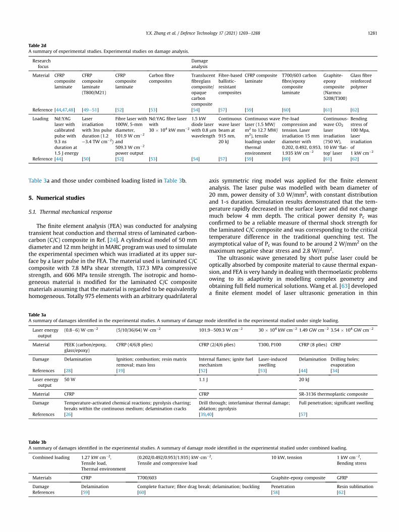
Table 2dA summary of experimental studies. Experimental studies on damage analysis.
Researchfocus
Damageanalysis
Material CFRPcompositelaminate
CFRPcompositelaminate(T800/M21)
CFRPcompositelaminate
Carbon fibrecomposites
Translucentfibreglasscomposite/opaquecarboncomposite
Fibre-basedballistic-resistantcomposites
CFRP compositelaminate
T700/603 carbonfibre/epoxycompositelaminate
Graphite-epoxycomposite(Narmco5208/T300)
Glass fibrereinforcedpolymer
Reference [44,47,48] [49e51] [52] [53] [54] [57] [59] [60] [61] [62]
Loading Nd:YAGlaser withcalibratedpulse with9.3 nsduration at1.5 J energy
Laserirradiationwith 3ns pulseduration (1.2e3.4 TW cm�2)
Fibre laser with100W, 5-mmdiameter,101.9 W cm�2
and509.3 W cm�2
power output
Nd:YAG fibre laserwith30 � 104 kW mm�2
1.5 kWdiode laserwith 0.8 mmwavelength
Continuouswave laserbeam at915 nm,20 kJ
Continuous wavelaser (1.5 MW/m2 to 12.7 MW/m2), tensileloadings underthermalenvironment
Pre-loadcompression andtension. Laserirradiation 15 mmdiameter with0.202, 0.492, 0.953,1.935 kW cm�2
Continuous-wave CO2
laserirradiation(750 W),10 kW ‘flat-top’ laser
Bendingstress of100 Mpa,laserirradiationof1 kW cm�2
Reference [44] [50] [52] [53] [54] [57] [59] [60] [61] [62]
Y.X. Zhang et al. / Defence Technology 17 (2021) 1269e1288 1281
Table 3a and those under combined loading listed in Table 3b.
5. Numerical studies
5.1. Thermal mechanical response
The finite element analysis (FEA) was conducted for analysingtransient heat conduction and thermal stress of laminated carbon-carbon (C/C) composite in Ref. [24]. A cylindrical model of 50 mmdiameter and 12mmheight in MARC programwas used to simulatethe experimental specimen which was irradiated at its upper sur-face by a laser pulse in the FEA. The material used is laminated C/Ccomposite with 7.8 MPa shear strength, 137.3 MPa compressivestrength, and 606 MPa tensile strength. The isotropic and homo-geneous material is modified for the laminated C/C compositematerials assuming that the material is regarded to be equivalentlyhomogeneous. Totally 975 elements with an arbitrary quadrilateral
Table 3aA summary of damages identified in the experimental studies. A summary of damage m
Laser energyoutput
(0.8e6) W$cm�2 (5/10/36/64) W$cm�2 101.
Material PEEK (carbon/epoxy,glass/epoxy)
CFRP (4/6/8 plies) CFRP
Damage Delamination Ignition; combustion; resin matrixremoval; mass loss
Intermec
References [28] [19] [52]
Laser energyoutput
50 W 1.1 J
Material CFRP CFRP
Damage Temperature-activated chemical reactions; pyrolysis charring;breaks within the continuous medium; delamination cracks
Drillablat
References [26] [39,4
Table 3bA summary of damages identified in the experimental studies. A summary of damage m
Combined loading 1.27 kW cm�2,Tensile load,Thermal environment
(0.202/0.492/0.953/1.935) kW$cm�
Tensile and compressive load
Materials CFRP T700/603
Damage Delamination Complete fracture; fibre drag breakReferences [59] [60]
axis symmetric ring model was applied for the finite elementanalysis. The laser pulse was modelled with beam diameter of20 mm, power density of 3.0 W/mm2, with constant distributionand 1-s duration. Simulation results demonstrated that the tem-perature rapidly decreased in the surface layer and did not changemuch below 4 mm depth. The critical power density Pc wasconfirmed to be a reliable measure of thermal shock strength forthe laminated C/C composite and was corresponding to the criticaltemperature difference in the traditional quenching test. Theasymptotical value of Pc was found to be around 2 W/mm2 on themaximum negative shear stress and 2.8 W/mm2.
The ultrasonic wave generated by short pulse laser could beoptically absorbed by composite material to cause thermal expan-sion, and FEA is very handy in dealing with thermoelastic problemsowing to its adaptivity in modelling complex geometry andobtaining full field numerical solutions. Wang et al. [63] developeda finite element model of laser ultrasonic generation in thin
ode identified in the experimental studied under single loading.
9e509.3 W cm�2 30 � 104 kW cm�2 1.49 GW cm�2 3.54 � 104 GW cm�2
(2/4/6 plies) T300, P100 CFRP (8 plies) CFRP
nal flames; ignite fuelhanism
Laser-inducedswelling
Delamination Drilling holes;evaporation
[53] [44] [34]
20 kJ
SR-3136 thermoplastic composite
through; interlaminar thermal damage;ion; pyrolysis
Full penetration; significant swelling
0] [57]
ode identified in the experimental studied under combined loading.
2, 10 kW, tension 1 kW cm�2,Bending stress
Graphite-epoxy composite GFRP
; delamination; buckling Penetration Resin sublimation[58] [62]
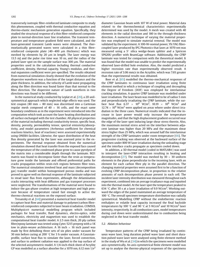
Y.X. Zhang et al. / Defence Technology 17 (2021) 1269e12881282
transversely isotropic fibre-reinforced laminate composite to studythis phenomenon, coupled with thermal conductive equation andthermo-elastic mechanism generation equation. Specifically, theystudied the structural response of a thin fibre-reinforced compositeplate to normal-direction laser line irradiation. The transient tem-perature and temperature gradient field were calculated, and thelaser-generated transient Lamb waves were obtained. The ther-moelastically generated waves were calculated in a thin fibre-reinforced composite plate (40e400 mm thickness) which wasmeshed by elements by 20 mm in length. The laser energy was13.5 mJ and the pulse rise time was 10 ns, and the radius of thepulsed laser spot on the sample surface was 300 mm. The materialproperties used in the calculation including thermal conductivecoefficient, density, thermal capacity, Young’s modulus, and ther-mal expansion coefficient were pre-specified. The results obtainedfrom numerical simulation clearly showed that the evolution of thedispersive waveform was a function of the target distance and theplate thickness. In addition, the velocity of Lamb wave propagatingalong the fibre direction was found faster than that normal to thefibre direction. The dispersive nature of Lamb waveform in twodirections was found to be different.
In the numerical study conducted by Leplat et al. [26], a 2D axil-symmetrical approach which neglected edge effects was used. Thetest coupon (80 mm � 80 mm) was discretised into a Cartesianregular mesh composed of 40 � 16 cells, and the exact sameboundary conditions as in the experiment were introduced into thecomputationwhich took account the laser heating distribution andall surface exchanged with the test chamber. All physical propertiesof the material including thermal conductivity tensor, specific heat,density, porosity, permeability tensor, spectral emissivity/absorp-tivity, and model parameters (Arrhenius coefficient for chemicalreactions kinetics, heat of reactions) were assessed experimentallyusing ONERA facilities. Likewise, the space distribution of the heatflux density generated by the laser was assessed prior to the ex-periments. The thermal response obtained from the numericalsimulation showed that heat transfer from the exposed face causedthe temperature of the condensed phase grow to cause pyrolysis ofthe matrix into a considerable depth through the laminate. M21matrix was found to decompose faster than the resin as tempera-ture grew inside the laminate and offered preferential paths forcracks propagation within resin-rich regions between fibre tows.The numerical simulation involved heat and mass (decompositiongas) transfer model within homogenised porous media and wasproved to agreewell on thermal response of the laminate subjectedto stead laser flux from experiments, although the delaminationcracks interacting with heat diffusion and gas transport processeswere neglected. The transformations of the material were found toinduce the gas-phase creation at high temperature and high pres-sure because of temperature raised fast enough to active thethermo-chemical reactions on the exposed surface.
Tresansky et al. [64] presented a numerical heat transfer modelto capture heat flow and material damage to polymer/carbon fibre-reinforced composites subjected to laser beam irradiation. COMSOLMultiphysics® numerical modelling program which includedpackages for heat transfer, fluid dynamics, electro-optics, solidmechanics, electricity and magnetism was used to establish thecomputational heat transfer model. A 2.5 mm thick, 20 ply carbonfibre/epoxy laminatewas tested using Cytec 5215 prepregwith a 1Ktow in plain-weave architecture. A 16 inch � 16 inch panel wasmade by first debulking three sets of six plies under vacuum for30 min before curing at 200 �C for 3 h under vacuum. A Gaussian-profile, surface heat flux to simulate the laser, forced convection,and surface to ambient radiation was applied to the top surface ofthe selected axisymmetric model. A 1/4-inch-thick sheet of AcryliteGP was modelled as a surface absorber for a 1070 nm, 6.12 mm 1/e2
diameter Gaussian beam with 107 W of total power. Material datarelated to the thermochemical characteristics experimentallydetermined was used by the model. A mesh was created with 40elements in the radial direction and 180 in the through-thicknessdirection. A numerical technique of varying the material proper-ties was employed to simulate material removal. The model wasvalidated by the experiment. A 100-W-nomial power, Yb:YAG fibre-coupled laser produced by IPG Photonics that lases at 1070 nmwasmeasured using a 5� silica wedge-beam splitter and a SpiriconSP620U profiler with BeamGage software. Additionally, the CFRPlaminate was tested for comparison with the theoretical model. Itwas found that the model was unable to predict the experimentallyobserved laser-drilled hole evolution. Also, the model predicted ahigher recession rate than experimentally observed result. Arecession rate of 3.06 mm/s in the Acryilite, which was 7.6% greaterthan the experimental results was obtained.
Boer et al. [65] modelled the thermo-mechanical responses ofthe CFRP laminates to continuous laser irradiation using finiteelement method in which a technique of coupling and decouplingthe Degree of Freedom (DOF) was employed for interlaminarcracking simulation. A quarter CFRP laminate was modelled underlaser irradiation. The laser beamwasmodelled to be of radius 5mmand perpendicularly irradiating the CFRP laminate, while the sur-face heat flux 6.37 � 106 W/m2, 10.19 � 106 W/m2 and12.74 � 106 W/m2 were applied on areas where under direct irra-diation in the three cases. Numerical results indicated that the in-crease in laser power would only increase the temperaturemagnitudes, and that the high displacement gradient occurred nearthe edge of the laser spot inducing large shear stress therein. Also,the maximum normal stress acted on the interface between adja-cent laminae was higher than 20 MPa and the maximum shearstress higher than 25 MPa, which was around half the interlaminarstrength of the CFRP laminates under room temperature [66]. Theprogressive cracking was observed at the backward surface of thespecimen under 800W laser irradiation during the unloading stageand the interface cracks propagate as specimen cooled down.
In addition, a 3D thermal model (coded in MATLAB®) was usedto interpret the laser-CFRP interaction resulting in heating anddecomposition [27]. The model was meshed by 30 � 30 uniformelements in the plane perpendicular to the incoming laser, with anelement for each carbon fibre ply in the parallel direction. Thechanging material properties were assumed first to be a function ofevolving CFRP decomposition phase, in proportion to the relativeamounts of each decomposition phase present in each cell. Theincident laser intensity distributionwas measured throughout eachexperiment, combined into an average irradiancemap and inputtedinto the thermal model. At the laser spot the temperature peaked to634 �C after 30 s at a laser irradiation of 9.9 W/cm2. Working out-ward the edges of the panel maintained an average temperature of100 �C. The overall specimen temperature distribution was radiallysymmetrical. Modelling CFRP without the endothermic reactionenthalpies or volatile heat capacity increased the final backsidetemperatures by 100 �C and 90 �C at 5 W/cm2 and 10 W/cm2 laserintensity, respectively. In all combustion cases, model temperaturesduring cool down were underestimated due to combustion beingneglected in the heat transfer model.
5.2. Ablation behaviour
Temperature patterns of the CFRP being irradiated by contin-uous wave laser, long duration pulsed wave laser and short dura-tion pulsed wave laser were analysed using finite element methodin the study ofWu et al. [34] inwhich the specimensweremodelledaxis-symmetrically. An axis-symmetrical finite element model wasset up to analyse the thermo-physical responses of the specimens
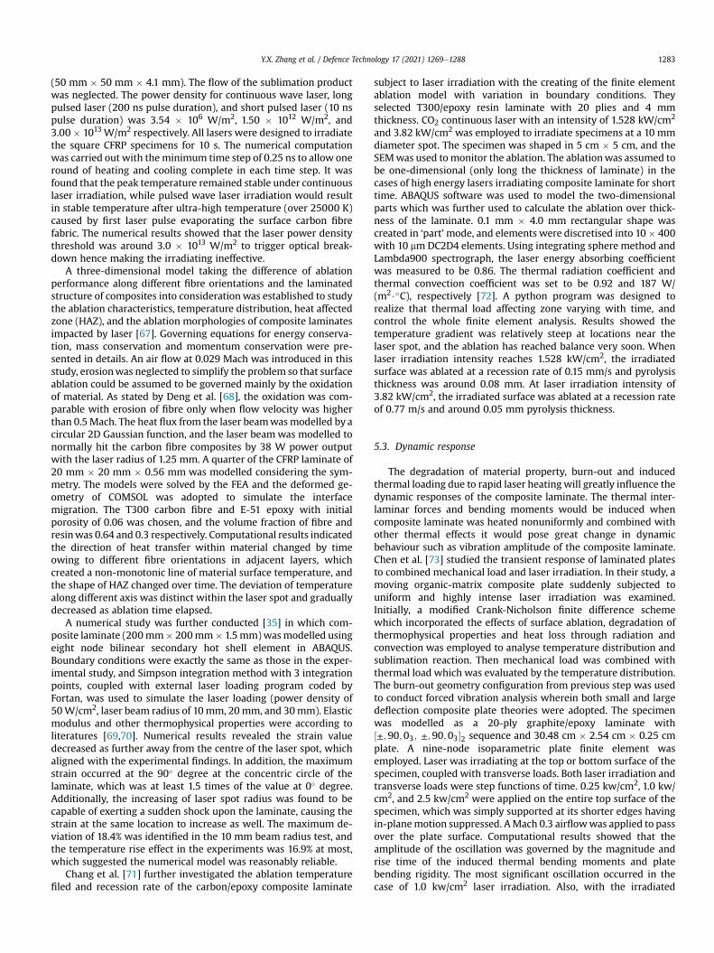
Y.X. Zhang et al. / Defence Technology 17 (2021) 1269e1288 1283
(50 mm � 50 mm � 4.1 mm). The flow of the sublimation productwas neglected. The power density for continuous wave laser, longpulsed laser (200 ns pulse duration), and short pulsed laser (10 nspulse duration) was 3.54 � 106 W/m2, 1.50 � 1012 W/m2, and3.00 � 1013 W/m2 respectively. All lasers were designed to irradiatethe square CFRP specimens for 10 s. The numerical computationwas carried out with theminimum time step of 0.25 ns to allow oneround of heating and cooling complete in each time step. It wasfound that the peak temperature remained stable under continuouslaser irradiation, while pulsed wave laser irradiation would resultin stable temperature after ultra-high temperature (over 25000 K)caused by first laser pulse evaporating the surface carbon fibrefabric. The numerical results showed that the laser power densitythreshold was around 3.0 � 1013 W/m2 to trigger optical break-down hence making the irradiating ineffective.
A three-dimensional model taking the difference of ablationperformance along different fibre orientations and the laminatedstructure of composites into considerationwas established to studythe ablation characteristics, temperature distribution, heat affectedzone (HAZ), and the ablation morphologies of composite laminatesimpacted by laser [67]. Governing equations for energy conserva-tion, mass conservation and momentum conservation were pre-sented in details. An air flow at 0.029 Mach was introduced in thisstudy, erosionwas neglected to simplify the problem so that surfaceablation could be assumed to be governed mainly by the oxidationof material. As stated by Deng et al. [68], the oxidation was com-parable with erosion of fibre only when flow velocity was higherthan 0.5Mach. The heat flux from the laser beamwasmodelled by acircular 2D Gaussian function, and the laser beamwas modelled tonormally hit the carbon fibre composites by 38 W power outputwith the laser radius of 1.25 mm. A quarter of the CFRP laminate of20 mm � 20 mm � 0.56 mm was modelled considering the sym-metry. The models were solved by the FEA and the deformed ge-ometry of COMSOL was adopted to simulate the interfacemigration. The T300 carbon fibre and E-51 epoxy with initialporosity of 0.06 was chosen, and the volume fraction of fibre andresinwas 0.64 and 0.3 respectively. Computational results indicatedthe direction of heat transfer within material changed by timeowing to different fibre orientations in adjacent layers, whichcreated a non-monotonic line of material surface temperature, andthe shape of HAZ changed over time. The deviation of temperaturealong different axis was distinct within the laser spot and graduallydecreased as ablation time elapsed.
A numerical study was further conducted [35] in which com-posite laminate (200mm� 200mm� 1.5mm)wasmodelled usingeight node bilinear secondary hot shell element in ABAQUS.Boundary conditions were exactly the same as those in the exper-imental study, and Simpson integration method with 3 integrationpoints, coupled with external laser loading program coded byFortan, was used to simulate the laser loading (power density of50W/cm2, laser beam radius of 10mm, 20mm, and 30mm). Elasticmodulus and other thermophysical properties were according toliteratures [69,70]. Numerical results revealed the strain valuedecreased as further away from the centre of the laser spot, whichaligned with the experimental findings. In addition, the maximumstrain occurred at the 90� degree at the concentric circle of thelaminate, which was at least 1.5 times of the value at 0� degree.Additionally, the increasing of laser spot radius was found to becapable of exerting a sudden shock upon the laminate, causing thestrain at the same location to increase as well. The maximum de-viation of 18.4% was identified in the 10 mm beam radius test, andthe temperature rise effect in the experiments was 16.9% at most,which suggested the numerical model was reasonably reliable.
Chang et al. [71] further investigated the ablation temperaturefiled and recession rate of the carbon/epoxy composite laminate
subject to laser irradiation with the creating of the finite elementablation model with variation in boundary conditions. Theyselected T300/epoxy resin laminate with 20 plies and 4 mmthickness. CO2 continuous laser with an intensity of 1.528 kW/cm2
and 3.82 kW/cm2 was employed to irradiate specimens at a 10 mmdiameter spot. The specimen was shaped in 5 cm � 5 cm, and theSEMwas used tomonitor the ablation. The ablationwas assumed tobe one-dimensional (only long the thickness of laminate) in thecases of high energy lasers irradiating composite laminate for shorttime. ABAQUS software was used to model the two-dimensionalparts which was further used to calculate the ablation over thick-ness of the laminate. 0.1 mm � 4.0 mm rectangular shape wascreated in ‘part’mode, and elements were discretised into 10� 400with 10 mmDC2D4 elements. Using integrating sphere method andLambda900 spectrograph, the laser energy absorbing coefficientwas measured to be 0.86. The thermal radiation coefficient andthermal convection coefficient was set to be 0.92 and 187 W/(m2$�C), respectively [72]. A python program was designed torealize that thermal load affecting zone varying with time, andcontrol the whole finite element analysis. Results showed thetemperature gradient was relatively steep at locations near thelaser spot, and the ablation has reached balance very soon. Whenlaser irradiation intensity reaches 1.528 kW/cm2, the irradiatedsurface was ablated at a recession rate of 0.15 mm/s and pyrolysisthickness was around 0.08 mm. At laser irradiation intensity of3.82 kW/cm2, the irradiated surface was ablated at a recession rateof 0.77 m/s and around 0.05 mm pyrolysis thickness.
5.3. Dynamic response
The degradation of material property, burn-out and inducedthermal loading due to rapid laser heatingwill greatly influence thedynamic responses of the composite laminate. The thermal inter-laminar forces and bending moments would be induced whencomposite laminate was heated nonuniformly and combined withother thermal effects it would pose great change in dynamicbehaviour such as vibration amplitude of the composite laminate.Chen et al. [73] studied the transient response of laminated platesto combined mechanical load and laser irradiation. In their study, amoving organic-matrix composite plate suddenly subjected touniform and highly intense laser irradiation was examined.Initially, a modified Crank-Nicholson finite difference schemewhich incorporated the effects of surface ablation, degradation ofthermophysical properties and heat loss through radiation andconvection was employed to analyse temperature distribution andsublimation reaction. Then mechanical load was combined withthermal load which was evaluated by the temperature distribution.The burn-out geometry configuration from previous step was usedto conduct forced vibration analysis wherein both small and largedeflection composite plate theories were adopted. The specimenwas modelled as a 20-ply graphite/epoxy laminate with½±;90;03; ±;90;03�2 sequence and 30.48 cm � 2.54 cm � 0.25 cmplate. A nine-node isoparametric plate finite element wasemployed. Laser was irradiating at the top or bottom surface of thespecimen, coupled with transverse loads. Both laser irradiation andtransverse loads were step functions of time. 0.25 kw/cm2, 1.0 kw/cm2, and 2.5 kw/cm2 were applied on the entire top surface of thespecimen, which was simply supported at its shorter edges havingin-planemotion suppressed. AMach 0.3 airflowwas applied to passover the plate surface. Computational results showed that theamplitude of the oscillation was governed by the magnitude andrise time of the induced thermal bending moments and platebending rigidity. The most significant oscillation occurred in thecase of 1.0 kw/cm2 laser irradiation. Also, with the irradiated

Y.X. Zhang et al. / Defence Technology 17 (2021) 1269e12881284
surface different from the pressure surface, vibration was elevated.The change in the stiffness and mass density of composite laminatewas also indicated, and the laser irradiation was found to increasethe peak amplitudes of vibration in all cases. However, the dynamicresponse of composite laminates was influenced by laser intensitywith the location of the plate surface being irradiated. Higher laserpower ensured neither greater escalation nor reduction of thevibration.
Chen et al. [72] studied the effects of laser irradiation onstrength reduction and on the dynamic and buckling characteristicsof organic-matrix composite laminates. The heat-transfer processwas modelled by a modified Crank-Nicholson finite differencescheme. In this study, a moving composite plate (20 ply30.48 cm � 2.54 cm � 0.254 cm graphite/epoxy laminated com-posite) was assumed to be suddenly exposed to highly intensivelaser irradiation (1.33 kW/cm2 and 2.79 kW/cm2). A Mach 0.3airflow was assumed to pass over the lamina. A nine-node iso-parametric plate finite element was employed. Computational re-sults showed that the higher the laser intensity, the faster thedegradation and the ablation of the material property. It alsoshowed that the worsening of material degradation and materialremoval did not result in monotonical decreasing of the naturalfrequency. The buckling load was found to have significantlyreduced as the laser exposure time increased.
5.4. Damage analysis
Complex chemical and physical processes including pyrolysis ofmatrix, formation and growth of pores and char, oxidation of re-sidual char and carbon fibres, thermal expansion and contraction,matrix cracking, and delamination may occur when CFRP com-posite with epoxy matrix was exposed to thermal environment[39]. Fig. 3 shows sectionmorphologies and surface topography of a2 mm thick autoclave cured CFRP laminate from CCF-700 carbon
Fig. 3. Cross section morphologies and the surface topography of
fibre and BA9916-II resin matrix under infrared laser of wavelength1064 nm, pulse duration 200ns and repetitive frequency 10 Hz for6 s, 8 s, and 10 s irradiation time by common optical microscopeand 3D microscope. An Arrhenius-Equation based model withmulti-step decomposition was employed to describe the mass-lossbehaviour of CFRP composite under elevated temperature by Zhaoet al. [56]. Additionally, a mesoscopic to macroscopic modelincluding thermal degradation of both matrix and fibres forobtaining the thermo-mechanical properties of the CFRP compositeunder heating, along with a progressive destruction program wasemployed for theoretical predictions. Specimens were predicted tofail in a progressive damageway at elevated temperatures, with thefailure sequence of 90� plies, ± 45� plies and 0� plies. Young’smodulus and residual strength decays predicted by the analyticalmodel was in well agreement with experiment observation.
Zhang et al. [74] developed a parametric program using APDLlanguage from ANSYS, based on three-dimensional Hashin princi-ple to study the accumulative damage of laminated compositesunder laser erosion. Specifically, the initiation, propagation andstructural damage of the macroscopic failure after laser erosion onthe composite laminates containing holes were simulated, yieldingcloud charts of damages of different layers under inner static strain.T300/KH304 [75] composite laminates containing hole withdifferent diameter (6.21, 7.97, 6.19, 6.15, 6.22, and 6.21 mm) and plyangle were selected. The SOLID46 laminate element in ANSYS waschosen for discretization, and refinements were applied near thehole where stress concentration was likely to occur. For unpene-trated laser erosion, the part being irradiated drastically decreasedin strength. Specifically, at erosion depth of 1.24 mm and 0.62 mm,the failure load for composite laminate was calculated to be38.39 kN and 50.36 kN, respectively, as compared to the failure loadof 63.57 kN when no laser erosion exerted upon composite lami-nate. By analysing the damage propagation, it was found that thedamage initiated from the ply with the largest angle and
CFRP laminates bring drilled under pulsed infrared laser [39].
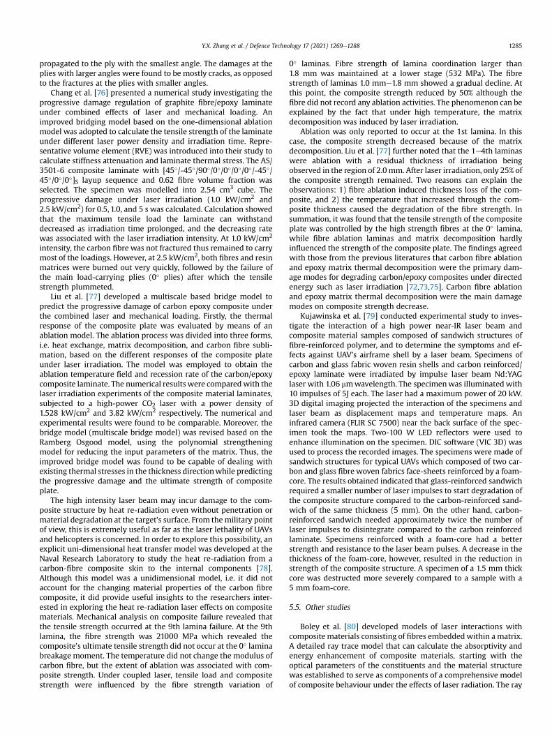
Y.X. Zhang et al. / Defence Technology 17 (2021) 1269e1288 1285
propagated to the ply with the smallest angle. The damages at theplies with larger angles were found to be mostly cracks, as opposedto the fractures at the plies with smaller angles.
Chang et al. [76] presented a numerical study investigating theprogressive damage regulation of graphite fibre/epoxy laminateunder combined effects of laser and mechanical loading. Animproved bridging model based on the one-dimensional ablationmodel was adopted to calculate the tensile strength of the laminateunder different laser power density and irradiation time. Repre-sentative volume element (RVE) was introduced into their study tocalculate stiffness attenuation and laminate thermal stress. The AS/3501-6 composite laminate with [45�/-45�/90�/0�/0�/0�/0�/-45�/45�/0�/0�]S layup sequence and 0.62 fibre volume fraction wasselected. The specimen was modelled into 2.54 cm3 cube. Theprogressive damage under laser irradiation (1.0 kW/cm2 and2.5 kW/cm2) for 0.5, 1.0, and 5 s was calculated. Calculation showedthat the maximum tensile load the laminate can withstanddecreased as irradiation time prolonged, and the decreasing ratewas associated with the laser irradiation intensity. At 1.0 kW/cm2
intensity, the carbon fibre was not fractured thus remained to carrymost of the loadings. However, at 2.5 kW/cm2, both fibres and resinmatrices were burned out very quickly, followed by the failure ofthe main load-carrying plies (0� plies) after which the tensilestrength plummeted.
Liu et al. [77] developed a multiscale based bridge model topredict the progressive damage of carbon epoxy composite underthe combined laser and mechanical loading. Firstly, the thermalresponse of the composite plate was evaluated by means of anablation model. The ablation process was divided into three forms,i.e. heat exchange, matrix decomposition, and carbon fibre subli-mation, based on the different responses of the composite plateunder laser irradiation. The model was employed to obtain theablation temperature field and recession rate of the carbon/epoxycomposite laminate. The numerical results were comparedwith thelaser irradiation experiments of the composite material laminates,subjected to a high-power CO2 laser with a power density of1.528 kW/cm2 and 3.82 kW/cm2 respectively. The numerical andexperimental results were found to be comparable. Moreover, thebridge model (multiscale bridge model) was revised based on theRamberg Osgood model, using the polynomial strengtheningmodel for reducing the input parameters of the matrix. Thus, theimproved bridge model was found to be capable of dealing withexisting thermal stresses in the thickness directionwhile predictingthe progressive damage and the ultimate strength of compositeplate.
The high intensity laser beam may incur damage to the com-posite structure by heat re-radiation even without penetration ormaterial degradation at the target’s surface. From themilitary pointof view, this is extremely useful as far as the laser lethality of UAVsand helicopters is concerned. In order to explore this possibility, anexplicit uni-dimensional heat transfer model was developed at theNaval Research Laboratory to study the heat re-radiation from acarbon-fibre composite skin to the internal components [78].Although this model was a unidimensional model, i.e. it did notaccount for the changing material properties of the carbon fibrecomposite, it did provide useful insights to the researchers inter-ested in exploring the heat re-radiation laser effects on compositematerials. Mechanical analysis on composite failure revealed thatthe tensile strength occurred at the 9th lamina failure. At the 9thlamina, the fibre strength was 21000 MPa which revealed thecomposite’s ultimate tensile strength did not occur at the 0� laminabreakage moment. The temperature did not change the modulus ofcarbon fibre, but the extent of ablation was associated with com-posite strength. Under coupled laser, tensile load and compositestrength were influenced by the fibre strength variation of
0� laminas. Fibre strength of lamina coordination larger than1.8 mm was maintained at a lower stage (532 MPa). The fibrestrength of laminas 1.0 mme1.8 mm showed a gradual decline. Atthis point, the composite strength reduced by 50% although thefibre did not record any ablation activities. The phenomenon can beexplained by the fact that under high temperature, the matrixdecomposition was induced by laser irradiation.
Ablation was only reported to occur at the 1st lamina. In thiscase, the composite strength decreased because of the matrixdecomposition. Liu et al. [77] further noted that the 1e4th laminaswere ablation with a residual thickness of irradiation beingobserved in the region of 2.0mm. After laser irradiation, only 25% ofthe composite strength remained. Two reasons can explain theobservations: 1) fibre ablation induced thickness loss of the com-posite, and 2) the temperature that increased through the com-posite thickness caused the degradation of the fibre strength. Insummation, it was found that the tensile strength of the compositeplate was controlled by the high strength fibres at the 0� lamina,while fibre ablation laminas and matrix decomposition hardlyinfluenced the strength of the composite plate. The findings agreedwith those from the previous literatures that carbon fibre ablationand epoxy matrix thermal decomposition were the primary dam-age modes for degrading carbon/epoxy composites under directedenergy such as laser irradiation [72,73,75]. Carbon fibre ablationand epoxy matrix thermal decomposition were the main damagemodes on composite strength decrease.
Kujawinska et al. [79] conducted experimental study to inves-tigate the interaction of a high power near-IR laser beam andcomposite material samples composed of sandwich structures offibre-reinforced polymer, and to determine the symptoms and ef-fects against UAV’s airframe shell by a laser beam. Specimens ofcarbon and glass fabric woven resin shells and carbon reinforced/epoxy laminate were irradiated by impulse laser beam Nd:YAGlaser with 1.06 mmwavelength. The specimenwas illuminated with10 impulses of 5J each. The laser had a maximum power of 20 kW.3D digital imaging projected the interaction of the specimens andlaser beam as displacement maps and temperature maps. Aninfrared camera (FLIR SC 7500) near the back surface of the spec-imen took the maps. Two-100 W LED reflectors were used toenhance illumination on the specimen. DIC software (VIC 3D) wasused to process the recorded images. The specimens were made ofsandwich structures for typical UAVs which composed of two car-bon and glass fibre woven fabrics face-sheets reinforced by a foam-core. The results obtained indicated that glass-reinforced sandwichrequired a smaller number of laser impulses to start degradation ofthe composite structure compared to the carbon-reinforced sand-wich of the same thickness (5 mm). On the other hand, carbon-reinforced sandwich needed approximately twice the number oflaser impulses to disintegrate compared to the carbon reinforcedlaminate. Specimens reinforced with a foam-core had a betterstrength and resistance to the laser beam pulses. A decrease in thethickness of the foam-core, however, resulted in the reduction instrength of the composite structure. A specimen of a 1.5 mm thickcore was destructed more severely compared to a sample with a5 mm foam-core.
5.5. Other studies
Boley et al. [80] developed models of laser interactions withcomposite materials consisting of fibres embeddedwithin a matrix.A detailed ray trace model that can calculate the absorptivity andenergy enhancement of composite materials, starting with theoptical parameters of the constituents and the material structurewas established to serve as components of a comprehensive modelof composite behaviour under the effects of laser radiation. The ray
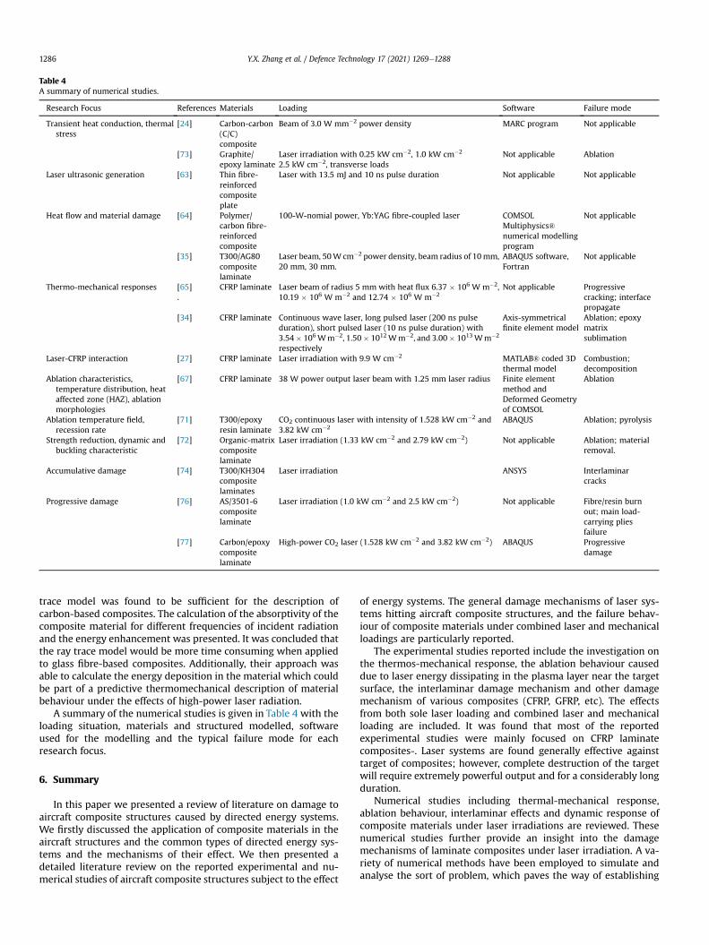
Table 4A summary of numerical studies.
Research Focus References Materials Loading Software Failure mode
Transient heat conduction, thermalstress
[24] Carbon-carbon(C/C)composite
Beam of 3.0 W mm�2 power density MARC program Not applicable
[73] Graphite/epoxy laminate
Laser irradiation with 0.25 kW cm�2, 1.0 kW cm�2
2.5 kW cm�2, transverse loadsNot applicable Ablation
Laser ultrasonic generation [63] Thin fibre-reinforcedcompositeplate
Laser with 13.5 mJ and 10 ns pulse duration Not applicable Not applicable
Heat flow and material damage [64] Polymer/carbon fibre-reinforcedcomposite
100-W-nomial power, Yb:YAG fibre-coupled laser COMSOLMultiphysics®numerical modellingprogram
Not applicable
[35] T300/AG80compositelaminate
Laser beam, 50W cm�2 power density, beam radius of 10mm,20 mm, 30 mm.
ABAQUS software,Fortran
Not applicable
Thermo-mechanical responses [65].
CFRP laminate Laser beam of radius 5 mm with heat flux 6.37 � 106 W m�2,10.19 � 106 W m�2 and 12.74 � 106 W m�2
Not applicable Progressivecracking; interfacepropagate
[34] CFRP laminate Continuous wave laser, long pulsed laser (200 ns pulseduration), short pulsed laser (10 ns pulse duration) with3.54� 106Wm�2, 1.50� 1012Wm�2, and 3.00� 1013Wm�2
respectively
Axis-symmetricalfinite element model
Ablation; epoxymatrixsublimation
Laser-CFRP interaction [27] CFRP laminate Laser irradiation with 9.9 W cm�2 MATLAB® coded 3Dthermal model
Combustion;decomposition
Ablation characteristics,temperature distribution, heataffected zone (HAZ), ablationmorphologies
[67] CFRP laminate 38 W power output laser beam with 1.25 mm laser radius Finite elementmethod andDeformed Geometryof COMSOL
Ablation
Ablation temperature field,recession rate
[71] T300/epoxyresin laminate
CO2 continuous laser with intensity of 1.528 kW cm�2 and3.82 kW cm�2
ABAQUS Ablation; pyrolysis
Strength reduction, dynamic andbuckling characteristic
[72] Organic-matrixcompositelaminate
Laser irradiation (1.33 kW cm�2 and 2.79 kW cm�2) Not applicable Ablation; materialremoval.
Accumulative damage [74] T300/KH304compositelaminates
Laser irradiation ANSYS Interlaminarcracks
Progressive damage [76] AS/3501-6compositelaminate
Laser irradiation (1.0 kW cm�2 and 2.5 kW cm�2) Not applicable Fibre/resin burnout; main load-carrying pliesfailure
[77] Carbon/epoxycompositelaminate
High-power CO2 laser (1.528 kW cm�2 and 3.82 kW cm�2) ABAQUS Progressivedamage
Y.X. Zhang et al. / Defence Technology 17 (2021) 1269e12881286
trace model was found to be sufficient for the description ofcarbon-based composites. The calculation of the absorptivity of thecomposite material for different frequencies of incident radiationand the energy enhancement was presented. It was concluded thatthe ray trace model would be more time consuming when appliedto glass fibre-based composites. Additionally, their approach wasable to calculate the energy deposition in the material which couldbe part of a predictive thermomechanical description of materialbehaviour under the effects of high-power laser radiation.
A summary of the numerical studies is given in Table 4 with theloading situation, materials and structured modelled, softwareused for the modelling and the typical failure mode for eachresearch focus.
6. Summary
In this paper we presented a review of literature on damage toaircraft composite structures caused by directed energy systems.We firstly discussed the application of composite materials in theaircraft structures and the common types of directed energy sys-tems and the mechanisms of their effect. We then presented adetailed literature review on the reported experimental and nu-merical studies of aircraft composite structures subject to the effect
of energy systems. The general damage mechanisms of laser sys-tems hitting aircraft composite structures, and the failure behav-iour of composite materials under combined laser and mechanicalloadings are particularly reported.
The experimental studies reported include the investigation onthe thermos-mechanical response, the ablation behaviour causeddue to laser energy dissipating in the plasma layer near the targetsurface, the interlaminar damage mechanism and other damagemechanism of various composites (CFRP, GFRP, etc). The effectsfrom both sole laser loading and combined laser and mechanicalloading are included. It was found that most of the reportedexperimental studies were mainly focused on CFRP laminatecomposites-. Laser systems are found generally effective againsttarget of composites; however, complete destruction of the targetwill require extremely powerful output and for a considerably longduration.
Numerical studies including thermal-mechanical response,ablation behaviour, interlaminar effects and dynamic response ofcomposite materials under laser irradiations are reviewed. Thesenumerical studies further provide an insight into the damagemechanisms of laminate composites under laser irradiation. A va-riety of numerical methods have been employed to simulate andanalyse the sort of problem, which paves the way of establishing

Y.X. Zhang et al. / Defence Technology 17 (2021) 1269e1288 1287
generic models of composite interaction with energy systems.Despite the fruitfulness of the current research, a few gaps for
further research to fill are identified in this paper. Hitherto most ofthe experimental studies have been focused on CFRP. There is still alarge room for further research on other types of compositesincluding carbon-carbon composite, Kevlar -epoxy composite,GFRP and window glass composite responding to energy hitting.Especially, studies that compare the performance of different typesof composite laminate to withstand consistent laser irradiationwould be highly constructive. In addition, studies on the distinctionof different types of energy system with identical power outputimpact on the same targets are highly recommended for futureresearch to understand the effects of the different energy systems.For numerical analysis, there are also room to further investigatethe numerical algorithm for better simulation of the contact andimpact between the direct energy and the target. More accuratematerial models for the composites considering the high energyimpact effects will need to be further developed. In addition,studies focusing on parallel contrast between the accuracy andefficiency of different numerical models on simulating laser effectson composites are also yet to be sufficed. Finally a recommendationfor further research is to conduct experimental and computationalinvestigation on prediction of the residual strength of compositestructures subject to laser damage for the purpose of structureintegrity assessment.
Declaration of competing interest
The authors declare that there is no conflict of interest.
Acknowledgement
Funding support from Department of Defence, Australia isacknowledged. The authors acknowledge the advice and valuablesuggestions on this research and paper writing from Dr. JohnWangfrom Defence Science and Technology Group, Australia.
References
[1] Botelho EC, Silva RA, Pardini LC, Rezende MC. A review on the developmentand properties of continuous fiber/epoxy/aluminum hybrid composites foraircraft structures. Mater Res 2006;9(3):247e56. https://doi.org/10.1590/S1516-14392006000300002.
[2] Bielawski R. Composite materials in military aviation and selected problemswith implementation. Rev Air Force Acad 2017;15(1):11e6. https://doi.org/10.19062/1842-9238.2017.15.1.2.
[3] Soutis C. Fibre reinforced composites in aircraft construction. Prog Aero Sci2005;41(2):143e51. https://doi.org/10.1016/j.paerosci.2005.02.004.
[4] Gay D. Composite materials: design and applications. CRC press; 2014.[5] Hawyes VJ, Curtis PT, Soutis C. Effect of impact damage on the compressive
response of composite laminates. Compos Appl Sci Manuf 2001;32(9):1263e70.
[6] Soutis C, Curtis PT. Prediction of the post-impact compressive strength of CFRPlaminated composites. Compos Sci Technol 1996;56(6):677e84. https://doi.org/10.1016/0266-3538(96)00050-4.
[7] Soutis C, Spearing SM. Compressive response of notched, woven fabric, facesheet honeycomb sandwich panels. Plast Rubber Composites 2002;31(9):392e7.
[8] Vogelesang LB, Vlot A. Development of fibre metal laminates for advancedaerospace structures. J Mater Process Technol 2000;103(1):1e5. https://doi.org/10.1016/S0924-0136(00)00411-8.
[9] Afaghi-Khatibi A, Lawcock G, Ye L, Mai YW. On the fracture mechanicalbehaviour of fibre reinforced metal laminates (FRMLs). Comput Methods ApplMech Eng 2000;185(2e4):173e90. https://doi.org/10.1016/S0045-7825(99)00258-3.
[10] Sinmazçelik T, Avcu E, Bora M€O, Ҫoban O. A review: fibre metal laminates,background, bonding types and applied test methods. Mater Des 2011;32(7):3671e85. https://doi.org/10.1016/j.matdes.2011.03.011.
[11] Davis J. Composite materials in engineering structures. Materials science andtechnologies series. New York: Nova Science; 2011.
[12] Yaghoubi Seyed, Liaw B. Thickness influence on ballistic impact behaviors ofGLARE 5 fiber-metal laminated beams: experimental and numerical studies.Compos Struct 2012;94(8):2585e98. https://doi.org/10.1016/
j.compstruct.2012.03.004.[13] Yaghoubi Seyed, Liaw B. Effect of lay-up orientation on ballistic impact be-
haviors of GLARE 5 FML beams. Int J Impact Eng 2013;54:138e48. https://doi.org/10.1016/j.ijimpeng.2012.10.007.
[14] Nturanabo F, Masu L, Kirabira JB. Novel applications of aluminium metalmatrix composites. In: Aluminum alloys and composites. IntechOpen; 2010.
[15] Han D, Pastrikakis V, Barakos GN. Helicopter performance improvement byvariable rotor speed and variable blade twist. Aero Sci Technol 2016;54:164e73. https://doi.org/10.1016/j.ast.2016.04.011. Elsevier Masson SAS.
[16] Stewart MK, Stewart C. Directed-energy weapons. In: Ciottone’s disaster.Medicine; 2016. p. 499e503.
[17] Nielsen PE. Effects of directed energy weapons. National Defense UnivWashington DC Center for Technology and National Security Policy; 1994.
[18] Weise THGG, Jung M, Langhans D, Gowin M. Overview of directed energyweapon developments, the 12th symposium on electromagnetic launchTechnology. IEEE; 2004. p. 483e9. https://doi.org/10.1109/elt.2004.1398128.
[19] Herr NC, Gonzales AE, Perram GP. Kinetics, evolving thermal properties, andsurface ignition of carbon fiber reinforced epoxy composite during laser-induced decomposition. Polym Degrad Stabil 2018;152:147e61. https://doi.org/10.1016/j.polymdegradstab.2018.04.007.
[20] Buckley JD. Carbon-carbon-an overview. Am Ceram Soc Bull 1988;67:364e8.[21] Fukuda K. The 676th lecture by the Japan society of mechanical engineers.
Lecture Text: Newest Technology for ACM; 1988.[22] Li HW, Amada S, Epinat M. Evaluation of the thermal shock shear strength of
carbon-carbon (C/C) composite by a laser irradiation technique. J Mater Pro-cess Technol 2003;138(1e3):423e8. https://doi.org/10.1016/S0924-0136(03)00111-0.
[23] Anand K, Gupta V, Dartfrod D. Failure mechanisms of laminated carbon-carbon composites-II. Under shear loads. Acta Metall Mater 1994;42(3):797e809. https://doi.org/10.1016/0956-7151(94)90275-5.
[24] Li HW, Amada S, Akiyama S. Thermal shock strength of carbon-carbon com-posite by laser irradiation technique based on shear strength criterion. FusionSci Technol 2001;40(3):265e73. https://doi.org/10.13182/FST01-A194.
[25] Uhlmann E, Spur G, Hocheng H, Liebelt S, Pan CT. The extent of laser-inducedthermal damage of UD and cross-ply composite laminates. Int J Mach ToolManufact 1999;39(4):639e50.
[26] Leplat G, Huchette C, Biasi V. Thermal and damage analysis of laser-induceddecomposition within carbon/epoxy composite laminates. J Fire Sci2016;34(5):361e84. https://doi.org/10.1177/0734904116653617.
[27] Herr NC. Degradation of carbon fiber reinforced polymer and graphite by laserheating. 2016.
[28] Berlin P, Dickman O, Larsson F. Effects of heat radiation on carbon/PEEK,carbon/epoxy and glass/epoxy composites. Composites 1992;23(4):235e43.https://doi.org/10.1016/0010-4361(92)90183-U.
[29] Griffis CA, Masumura RA, Chang CI. Thermal response of graphite epoxycomposite subjected to rapid heating. J Compos Mater 1981;15(5):427e42.
[30] Lacroix F, Allheily V, Diener K, Eichhorn A, Gillet M, L’Hostis G. Thermo-mechanical behavior of aeronautic structural carbon epoxy composite sub-mitted to a laser irradiation. Compos Struct 2016;143:220e9. https://doi.org/10.1016/j.compstruct.2016.02.009.
[31] Sankaranarayanan S, Emminger H, Kar A. Energy loss in the plasma duringlaser drilling. J Phys Appl Phys 1999;32(14):1605e11. https://doi.org/10.1088/0022-3727/32/14/310.
[32] Thiyagarajan M, Thompson S. Optical breakdown threshold investigation of1064 nm laser induced air plasmas. J Appl Phys 2012;111(7):073302.
[33] Ali AW. On laser air breakdown, threshold power and laser generated channellength. 1983. p. 1e19. Thesis.
[34] Wu CW, Wu XQ, Huang CG. Ablation behaviors of carbon reinforced polymercomposites by laser of different operation modes. Optic Laser Technol2015;73:23e8. https://doi.org/10.1016/j.optlastec.2015.04.008.
[35] Zhu K, Long LC, Chen M, Liu SB. Strain test and analysis of composite lami-nated plate under laser irradiation. High Power Laser and Particle Beams2011;23(12):3265e70.
[36] Stratoudaki T. Optical absorption of epoxy resin and its role in the laser ul-trasonic generation mechanism. Compos Mater 2003:965e72. https://doi.org/10.1063/1.1570238.
[37] Pan S, Li Q, Xian Z, Su N, Zeng F. The effects of laser parameters and theablation mechanism in laser ablation of c/sic composite. Materials2019;12(19). https://doi.org/10.3390/ma12193076.
[38] Wu ZX, Li JW, Huang CJ, Huang RJ, Li LF. Effect of gamma irradiation on themechanical behavior, thermal properties and structure of epoxy/glass-fibercomposite. J Nucl Mater 2013;441(1e3):67e72. https://doi.org/10.1016/j.jnucmat.2013.05.041.
[39] Liu YC, Liu YC, Wu CW, Song HW, Huang CG. Interaction between pulsedinfrared laser and carbon fiber reinforced polymer composite laminates. HighPower Lasers, High Energy Lasers, Silicon-based Photonic Integration 2016:10152. https://doi.org/10.1117/12.2246836.
[40] Liu YC, Wu CW, Huang YH, Song HW, Huang CG. Interlaminar damage ofcarbon fiber reinforced polymer composite laminate under continuous wavelaser irradiation. Optic Laser Eng 2017;88:91e101. https://doi.org/10.1016/j.optlaseng.2016.08.001.
[41] Giannadakis K, Varna J. Effect of thermal aging and fatigue on failure resis-tance of aerospace composite materials. IOP Conf Ser Mater Sci Eng 2009;5.https://doi.org/10.1088/1757-899X/5/1/012020.
[42] Nan P, Shen Z, Han B, Ni X. The influences of laminated structure on the
Y.X. Zhang et al. / Defence Technology 17 (2021) 1269e12881288
ablation characteristics of carbon fiber composites under CW laser irradiation.Optic Laser Technol 2019;116:224e31. https://doi.org/10.1016/j.optlastec.2019.03.015.
[43] Sha JJ, Dai JX, Li J, Wei ZQ, Hausherr JM, Krenkel W. Influence of carbon fiberssurface state on interlaminar shear properties of CFRP laminate. ComposInterfac 2013;20(8):543e52. https://doi.org/10.1080/15685543.2013.813188.
[44] Gay E, Berthe L, Boustie M, Arrigoni M, Trombini M. Study of the response ofCFRP composite laminates to a laser-induced shock. Compos B Eng 2014;64:108e15. https://doi.org/10.1016/j.compositesb.2014.04.004.
[45] Parga-Landa B, Vlegels S, Hern�andez-Olivares F, Clark SD. Analytical simula-tion of stress wave propagation in composite materials. Compos Struct1999;45(2):125e9.
[46] Zaretsky E, deBotton G, Perl M. The response of a glass fibers reinforced epoxycomposite to an impact loading. Int J Solid Struct 2004;41(2):569e84. https://doi.org/10.1016/j.ijsolstr.2003.09.026.
[47] Yu A, Gupta V. Measurement of in situ fiber/matrix interface strength ingraphite/epoxy composites. Compos Sci Technol 1998;58(11):1827e37.https://doi.org/10.1016/S0266-3538(98)00048-7.
[48] Riedel W, Nahme H, Thoma K. Equation of state properties of modern com-posite materials. Bull Am Phys Soc 2003;48(4):85.
[49] Ecault R, Boustie M, Touchard F, Berthe L, Chocinski-Arnault L, Ehrhart B,Bockenheimer C. Laser shock waves technique for damage threshold deter-mination of aeronautic composite materials, ECCM 2012 - composites atVenice. In: Proceedings of the 15th European conference on composite ma-terials; 2012. p. 24e8.
[50] Ecault R, Boustie M, Berthe L, Touchard F. Laser shock waves: a way to test anddamage composite materials for aeronautic applications. In: Internationalhigh-power laser ablation conference. Santa Fe, USA. April 30theMay 3rd2012.
[51] Ecault R, Boustie M, Touchard F, Berthe L, Chocinski-Arnault L, Ehrhart B,Bockenheimer C. Damage of composite materials by use of laser driven shockwaves. In: 26th ASC annual technical conference. Montreal, Canada.September 27th 2011.
[52] Garcia JD, Joyce P, Brownell C. Thermal damage behind HEL-irradiated carbonfiber e reinforced polymer skin. J Directed Energy 2017;6(1).
[53] Voisey KT, Fouquet S, Roy D, Clyne TW. Fibre swelling during laser drilling ofcarbon fibre composites. Optic Laser Eng 2006;44(11):1185e97. https://doi.org/10.1016/j.optlaseng.2005.10.008.
[54] Wu SS, Boley CD, Florando JN, Leblanc MM, Lowdermilk WH, Rubenchik SM,Stanley JR. Deep penetration in aerospace composite materials using near-infrared laser radiation (No. LLNL-TR-608235). Livermore, CA (UnitedStates): Lawrence Livermore National Lab.(LLNL); 2012.
[55] Griffis CA, Nemes JA, Stonesifer FR, Chang CI. Degradation in strength oflaminated composites subjected to intense heating and mechanical loading.Environ Eff Composite Mater 1988;3:361e80.
[56] Kumar S. Laser-induced damage to mechanically loaded laminated, (March).2018.
[57] Candan C, Seymen AA, Karatutlu A, Tiken M, Midilli Y, Orhan E, Berbero�glu H,Ortaç. Performance evaluation of fiber-based ballistic composites against laserthreats. Optic Laser Eng 2019;121:54e60. https://doi.org/10.1016/j.optlaseng.2019.03.016.
[58] Allheily V, Lacroix F, Eichhorn A, Merlat L, L’Hostis G, Durand B. An experi-mental method to assess the thermo-mechanical damage of CFRP subjected toa highly energetic 1.07 mm-wavelength laser irradiation. Compos B Eng2016;92:326e31.
[59] Zhao W, Huang Y, Song H, Huang C. Residual strength and damage mecha-nisms of laminated carbon fiber reinforced polymer under thermal environ-ments and laser irradiations. Polym Eng Sci 2018;58(12):2311e9. https://doi.org/10.1002/pen.24853.
[60] Long LC, Wang TT, Liu LT. Tensile and compression test of carbon/epoxycomposite laminate under combined action of laser irradiation and load.
Mater Res Innovat 2015;19:S9171e6. https://doi.org/10.1179/1432891715Z.0000000001953.
[61] Kibler KG, Carter HG, Eisenmann JR. Response of graphite composites to laserradiation (No. FZM-6661). General Dynamics Fort Worth Tx Fort Worth Div;1977.
[62] Kumar S, Das NR. Laser-induced damage to mechanically loaded laminates. IntJ Sci Eng Res 2016;7(1):2229e5518.
[63] Wang J, Shen Z, Xu B, Ni X, Guan J, Lu J. Numerical simulation of laser-generated Lamb wave by finite element method in thin transverselyisotropic laminate composite. Chin Optic Lett 2005;3(101):S308e10.
[64] Tresansky AC, Joyce P, Radice J, Watkins J. Numerical modeling of high-energylaser effects in polymer and composite materials. J Directed Energy 2014;5:137e58.
[65] de Boer A, van Zuijlen AH, Bijl H. Review of coupling methods for non-matching meshes. Comput Methods Appl Mech Eng 2007;196(8):1515e25.https://doi.org/10.1016/j.cma.2006.03.017.
[66] Svensson D, Alfredsson KS, Biel A, Stigh U. Measurement of cohesive laws forinterlaminar failure of CFRP. Compos Sci Technol 2014;100:53e62. https://doi.org/10.1016/j.compscitech.2014.05.031.
[67] Nan P, Shen Z, Han B, Ni X. The influences of laminated structure on theablation characteristics of carbon fibre composites under CW laser irradiation.Optic Laser Technol 2019;116:224e31.
[68] Deng D, Jijun Y, Xiangqiao Y, Fei H, Luo Xiaoguang. Engineering method forthe thermal mechanical erosion of C/C composite with the mesoscale ablationmodel. Polym Polym Compos 2014;22(2):181e6.
[69] Chen Ming. Response analysis and experimental test of composite structureirradiated by laser. Beijing: Beijing University of Technology; 2010.
[70] Zhang JH, Sheng ZM, Sun JT. Missile and launch vehicle composite structuredesign guidelines. Beijing: China Astronautic Publishing House; 1999.
[71] Xinlong C, Zhengliang L, Bo H, Kuan H. Analysis of carbon/epoxy laminatesablation subject to laser irradiation. Infrared Laser Eng 2009;40(9):1691e2386.
[72] Chen JK, Perea A, Allahdadi FA. A study of laser/composite material in-teractions. Compos Sci Technol 1995;54(1):35e44. https://doi.org/10.1016/0266-3538(95)00034-8.
[73] Chen JK, Perea A, Allahdadi FA. Laser effects on the dynamic response oflaminated composites. Composites Eng 1995;5(9):1135e47. https://doi.org/10.1016/0961-9526(95)00049-S. Elsevier Science Ltd.
[74] Zhang F, Zhang GC, Li K, Li YD. Analysis on three dimension accumulativedamage of laminated composites after laser erosion. Journal of Solid RocketTechnology 2009;32(2):218e29.
[75] Zhao Q. Static strength failure analysis of composite laminates with a hole.(Doctoral dissertation, Nanjing University of Aeronautics and Astronautics).http://cdmd.cnki.com.cn/Article/CDMD-10287-2005079392.htm. 2005.
[76] Xinlong C, Zhengliang L, Texi C, Pengya F. Damage rule analysis of compositematerials laminate under the combined effects of laser and mechanicalloading. Infrared Laser Eng 2011;40(10). 10-10.
[77] Liu W, Chang X, Zhang X, Zhang Y. Progressive damage analysis of carbon/epoxy laminates under couple laser and mechanical loading. Results Phys2017;7:995e1005. https://doi.org/10.1016/j.rinp.2017.02.011.
[78] Cozzens RF, Evans M, Duncan J. High energy laser lethality involving carbonfibre reinforced composite material. Report NRL/MR/6120-1-9485. NavalResearch Laboratory Memorandum; 2013.
[79] Kujawinska M, Kustron K, Siedlecki K, Malesa M. Investigations of high powerlaser beam interaction with composite materials by means of digital imagecorrelation and thermography. In: High-power lasers: Technology and sys-tems, platforms, and effects, vol. 10436. International Society for Optics andPhotonics; 2017. 104360H.
[80] Boley CD, Rubenchik AM. Modeling of laser interactions with compositematerials. Appl Optic 2013;52(14):3329e37. https://doi.org/10.1364/AO.52.003329.