damage to storage tanks caused by the 2011 · pdf file1 damage to storage tanks caused by the...
TRANSCRIPT
1
DAMAGE TO STORAGE TANKS CAUSED BY THE 2011 TOHOKU EARTHQUAKE AND TSUNAMI AND PROPOSAL FOR STRUCTURAL ASSESSMENT METHOD
FOR CYLINDRICAL STORAGE TANKS
Takashi Ibata Isho Nakachi
Dr. Kazuo Ishida Junichi Yokozawa
IHI Corporation
KEYWORDS: cylindrical storage tank, tsunami, smoothed particle hydrodynamics, buckling analysis, 2011 Tohoku earthquake
ABSTRACT
On 11 March, 2011, the damage caused by the Tohoku Earthquake and Tsunami shocked the world. The unprecedented scale was catastrophic, and caused devastating destruction to both people’s lives and the Japanese landscape. One such damage was to storage tanks, a necessary infrastructure for storage of materials needed for everyday life. In order to prevent future damages, this paper will share valuable feedback from actual damages, as well as the results from studies conducted to assess the potential impact of future earthquakes and ensuing tsunamis in order to reduce damage to future storage tanks.
This paper addresses the following points:
1. Report of actual damages to storage tanks caused by the 2011 Tohoku Earthquake and Tsunami
2. Outline the “simplified evaluation method” for estimate of tsunami forces to flat bottom, cylindrical storage tanks developed by the Fire and Disaster Management Agency of Japan (FDMA) based on experimental results
3. Comparison of the “simplified evaluation method” for structural integrity of cylindrical storage tanks applying tsunami forces as calculated using FDMA methodology with actual tank damages. We also studied and verified the effects of tsunami water intrusion into the gap between tank bottom plate and foundation.
4. FEM buckling analysis of outer steel tank wall for a single containment tank loaded by the external pressure exerted by a tsunami
5. Coupled analysis between cylindrical storage tank and tsunami forces using the Smoothed Particle Hydrodynamics (SPH) Method
6. Conclusion and technical issues
2
1. INTRODUCTION
On 11 March 2011, the magnitude-9.0 Tohoku Earthquake triggered a Tsunami which hit Japan with an unprecedented height of water. Production and storage facilities located along the coast were directly impacted and the extraordinary disaster that followed was mainly due to the Tsunami.
Damage to many cylindrical oil storage tanks occurred due to sliding, floating, overturning, steel wall buckling and collapse due to the forces of the tsunami. Traditionally, production and storage facilities have not been designed to withstand tsunami forces and inundation. However, since significant earthquakes are predicted in the future with epicenters near Tokai, Tonankai and/or Nankai, the reassessment of the safety and countermeasures for protection of the storage tanks to future Tsunamis are outstanding issues. The establishment of safety guidelines and strength assessments for cylindrical storage tanks against tsunami has been studied by the IHI team from the following point of view.
(1) Validation of the “simplified evaluation method” for storage tanks developed by FDMA based on actual damages to storage tanks
(2) Impact of predicted tsunami disasters to low temperature single containment gas storage tanks and study of issues.
(3) Development of evaluation method for structural integrity checking of the outer steel wall single containment (double metallic wall) tanks using coupled analysis between wall and tsunami force by Smoothed Particle Hydrodynamics (SPH) method.
IHI introduces, for the first time, a methodology for evaluating structural integrity of cylindrical tanks when subjected to tsunami forces and effects.
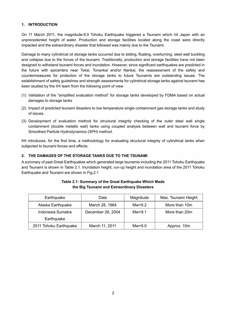
2. THE DAMAGES OF THE STORAGE TANKS DUE TO THE TSUNAMI A summary of past Great Earthquakes which generated large tsunamis including the 2011 Tohoku Earthquake and Tsunami is shown in Table 2.1. Inundation height, run-up height and inundation area of the 2011 Tohoku Earthquake and Tsunami are shown in Fig.2.1
Table 2.1: Summary of the Great Earthquake Which Made the Big Tsunami and Extraordinary Disasters
Earthquake Date Magnitude Max. Tsunami Height
Alaska Earthquake March 28, 1964 Mw=9.2 More than 10m
Indonesia Sumatra
Earthquake
December 26, 2004 Mw=9.1 More than 20m
2011 Tohoku Earthquake March 11, 2011 Mw=9.0 Approx. 10m
3
Figure 2.1: Inundation Height, Run-Up Height and Inundation Area of the 2011 Tohoku Earthquake and Tsunami.1)
There were so many storage tanks along the coast damaged by the 2011 Earthquake and Tsunami. Examples of damaged storage tanks are shown in Fig.2.2.
Figure 2.2: Examples of Damaged Storage Tanks2), 3)
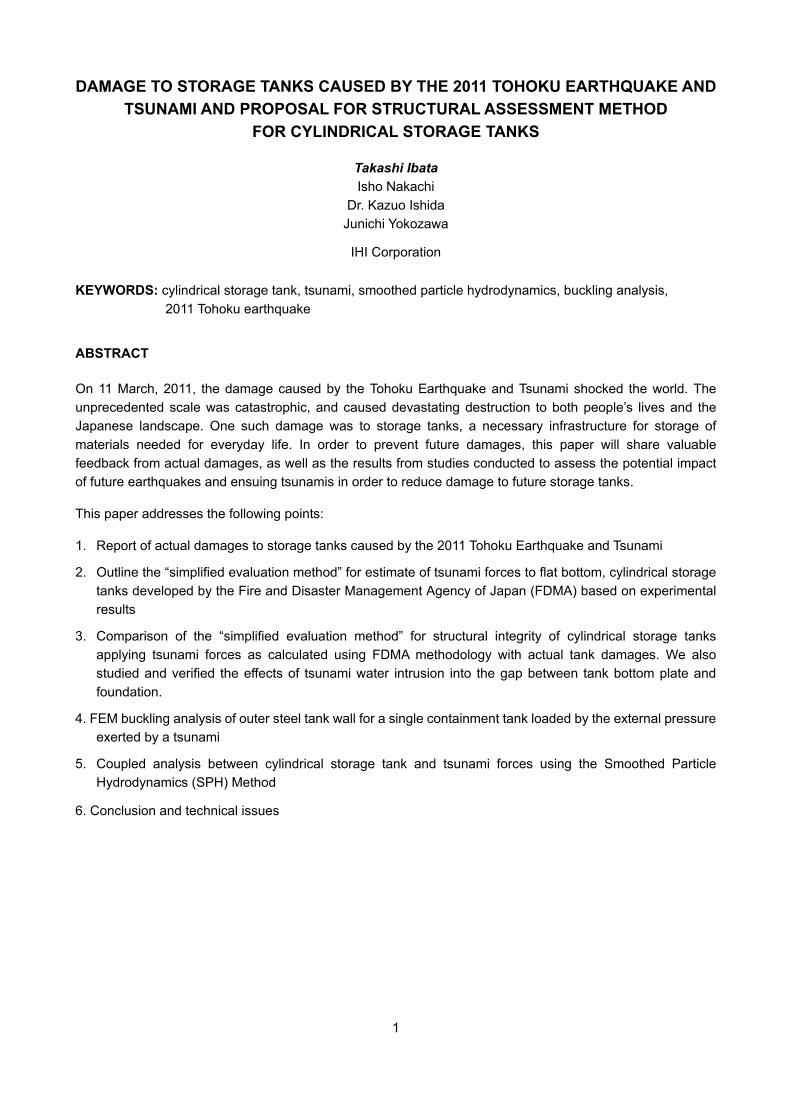
Definition of Term
Tsunami propagation Tsunami inundation Tsunami run-up
Tsunami height
Mean sea surface Inundation height
Run-up height
Inundation depth
Ground elevation
Inundation height
Run-up height
50km2 - 30km2 - 50km2 20km2 - 30km2 10km2 - 20km2 0km2 - 50km2
Aomori pref.
Iwate pref.
Miyagi pref.
Fukushima pref.
Ibaraki pref.
Chiba pref.
Aomori pref.
Iwate pref.
Miyagi pref.
Fukushima pref.
Ibaraki pref.
4
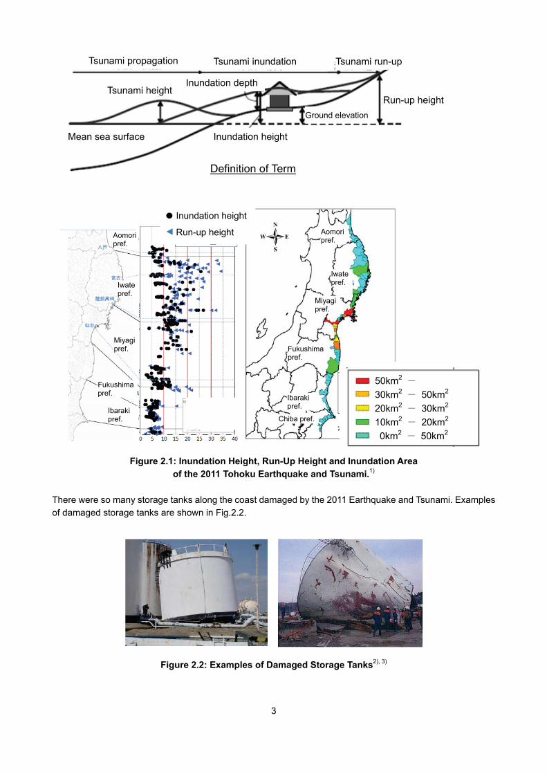
FDMA reported that 167 tanks were damaged. Of those, 120 tanks had capacities less than 500kl. There was no damage to tanks with capacities larger than10,000kl, but the piping for 27 of these tanks was damaged. Various types of tank damage caused by the tsunami are shown in Fig2.3
Figure 2.3: Various Types of Damage to Oil Storage Tanks by Tsunami 4)
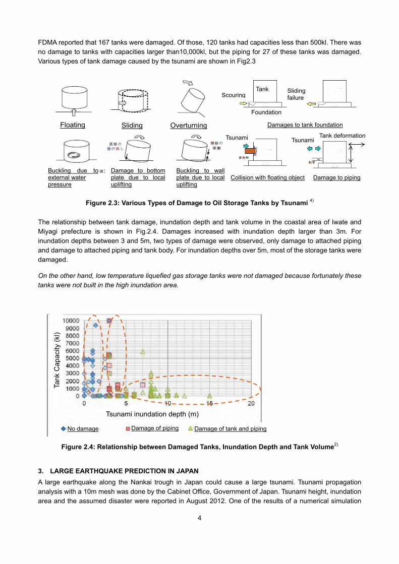
The relationship between tank damage, inundation depth and tank volume in the coastal area of Iwate and Miyagi prefecture is shown in Fig.2.4. Damages increased with inundation depth larger than 3m. For inundation depths between 3 and 5m, two types of damage were observed, only damage to attached piping and damage to attached piping and tank body. For inundation depths over 5m, most of the storage tanks were damaged.
On the other hand, low temperature liquefied gas storage tanks were not damaged because fortunately these tanks were not built in the high inundation area.
Figure 2.4: Relationship between Damaged Tanks, Inundation Depth and Tank Volume2)
3. LARGE EARTHQUAKE PREDICTION IN JAPAN A large earthquake along the Nankai trough in Japan could cause a large tsunami. Tsunami propagation analysis with a 10m mesh was done by the Cabinet Office, Government of Japan. Tsunami height, inundation area and the assumed disaster were reported in August 2012. One of the results of a numerical simulation
Floating Sliding Overturning
Buckling due to external water pressure
Damage to bottom plate due to local uplifting
Buckling to wall plate due to local uplifting
Tank
Foundation
Damages to tank foundation
Scouring Sliding failure
Collision with floating object Damage to piping
Tsunami Tsunami Tank deformation
Tsunami inundation depth (m)
Tank
Cap
acity
(kl)
No damage Damage of piping Damage of tank and piping
5
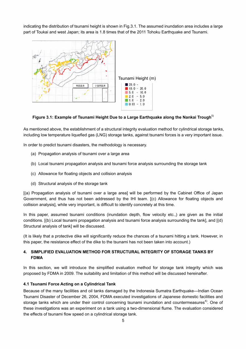
indicating the distribution of tsunami height is shown in Fig.3.1. The assumed inundation area includes a large part of Toukai and west Japan; its area is 1.8 times that of the 2011 Tohoku Earthquake and Tsunami.
Figure 3.1: Example of Tsunami Height Due to a Large Earthquake along the Nankai Trough5)
As mentioned above, the establishment of a structural integrity evaluation method for cylindrical storage tanks, including low temperature liquefied gas (LNG) storage tanks, against tsunami forces is a very important issue.
In order to predict tsunami disasters, the methodology is necessary.
(a) Propagation analysis of tsunami over a large area
(b) Local tsunami propagation analysis and tsunami force analysis surrounding the storage tank
(c) Allowance for floating objects and collision analysis
(d) Structural analysis of the storage tank
[(a) Propagation analysis of tsunami over a large area] will be performed by the Cabinet Office of Japan Government, and thus has not been addressed by the IHI team. [(c) Allowance for floating objects and collision analysis], while very important, is difficult to identify concretely at this time.
In this paper, assumed tsunami conditions (inundation depth, flow velocity etc.,) are given as the initial conditions. [(b) Local tsunami propagation analysis and tsunami force analysis surrounding the tank], and [(d) Structural analysis of tank] will be discussed.
(It is likely that a protective dike will significantly reduce the chances of a tsunami hitting a tank. However, in this paper, the resistance effect of the dike to the tsunami has not been taken into account.)
4. SIMPLIFIED EVALUATION METHOD FOR STRUCTURAL INTEGRITY OF STORAGE TANKS BY FDMA
In this section, we will introduce the simplified evaluation method for storage tank integrity which was proposed by FDMA in 2009. The suitability and limitation of this method will be discussed hereinafter.
4.1 Tsunami Force Acting on a Cylindrical Tank Because of the many facilities and oil tanks damaged by the Indonesia Sumatra Earthquake—Indian Ocean Tsunami Disaster of December 26, 2004, FDMA executed investigations of Japanese domestic facilities and storage tanks which are under their control concerning tsunami inundation and countermeasures4). One of these investigations was an experiment on a tank using a two-dimensional flume. The evaluation considered the effects of tsunami flow speed on a cylindrical storage tank.
Tsunami Height (m)
6
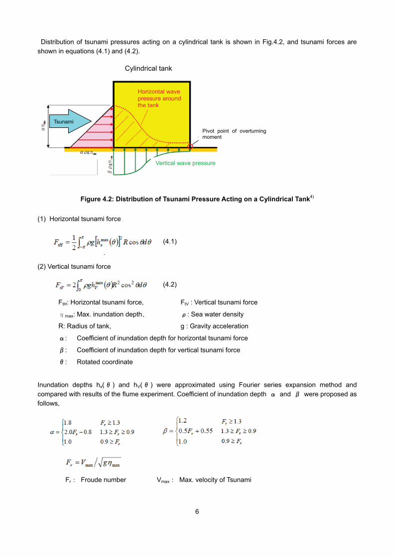
Distribution of tsunami pressures acting on a cylindrical tank is shown in Fig.4.2, and tsunami forces are shown in equations (4.1) and (4.2).
Figure 4.2: Distribution of Tsunami Pressure Acting on a Cylindrical Tank4)
(1) Horizontal tsunami force
(2) Vertical tsunami force
FtH: Horizontal tsunami force, FtV : Vertical tsunami force
ηmax: Max. inundation depth、 ρ: Sea water density
R: Radius of tank, g : Gravity acceleration
α: Coefficient of inundation depth for horizontal tsunami force
β: Coefficient of inundation depth for vertical tsunami force
θ: Rotated coordinate
Inundation depths hx(θ ) and hV(θ ) were approximated using Fourier series expansion method and compared with results of the flume experiment. Coefficient of inundation depth α and β were proposed as follows,
Fr: Froude number Vmax: Max. velocity of Tsunami
Vertical wave pressure
Cylindrical tank
Horizontal wave pressure around the tank
Tsunami
Pivot point of overturning moment
(4.1)
(4.2)
7
4.2 Simplified Evaluation Method for Tank Damage by Tsunami To predict sliding, floating (including lifting up) and overturning of the cylindrical storage tanks, the simplified evaluation method of tank damage by tsunami was proposed by FDMA4).
In this method, tank self-weight including internal liquid and friction force between tank bottom plate and foundation are compared to vertical and horizontal tsunami forces respectively. And then, it is decided whether tanks are damaged or not. Steel wall buckling due to the difference between external and internal pressure is predicted by the simplified formula taken from the shell buckling theory6).
4.3 Validity of the Simplified Evaluation Method for Determining Storage Tanks Damage Based on the Actual Tank Damages
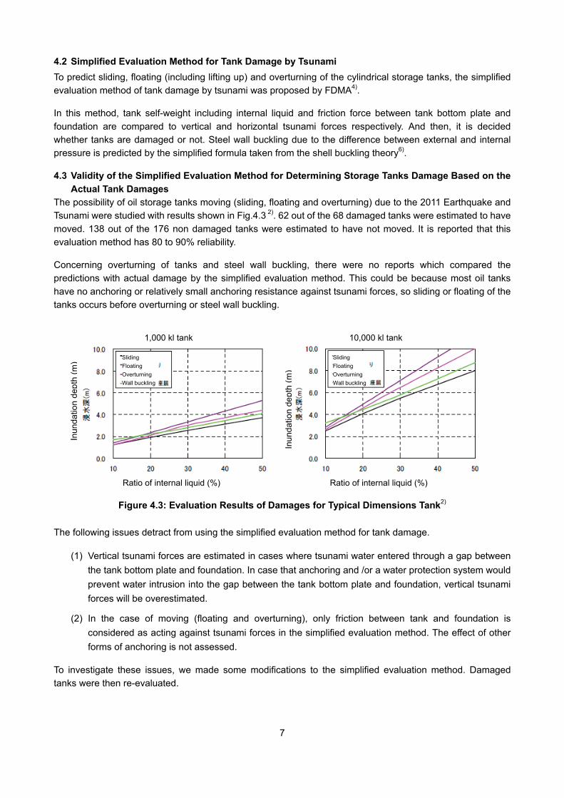
The possibility of oil storage tanks moving (sliding, floating and overturning) due to the 2011 Earthquake and Tsunami were studied with results shown in Fig.4.3 2). 62 out of the 68 damaged tanks were estimated to have moved. 138 out of the 176 non damaged tanks were estimated to have not moved. It is reported that this evaluation method has 80 to 90% reliability.
Concerning overturning of tanks and steel wall buckling, there were no reports which compared the predictions with actual damage by the simplified evaluation method. This could be because most oil tanks have no anchoring or relatively small anchoring resistance against tsunami forces, so sliding or floating of the tanks occurs before overturning or steel wall buckling.
Figure 4.3: Evaluation Results of Damages for Typical Dimensions Tank2) The following issues detract from using the simplified evaluation method for tank damage.
(1) Vertical tsunami forces are estimated in cases where tsunami water entered through a gap between the tank bottom plate and foundation. In case that anchoring and /or a water protection system would prevent water intrusion into the gap between the tank bottom plate and foundation, vertical tsunami forces will be overestimated.
(2) In the case of moving (floating and overturning), only friction between tank and foundation is considered as acting against tsunami forces in the simplified evaluation method. The effect of other forms of anchoring is not assessed.
To investigate these issues, we made some modifications to the simplified evaluation method. Damaged tanks were then re-evaluated.
Ratio of internal liquid (%) Ratio of internal liquid (%)
Inun
datio
n de
pth
(m)
Inun
datio
n de
pth
(m)
10,000 kl tank 1,000 kl tank
Sliding Floating Overturning Wall buckling
Sliding Floating Overturning Wall buckling
8
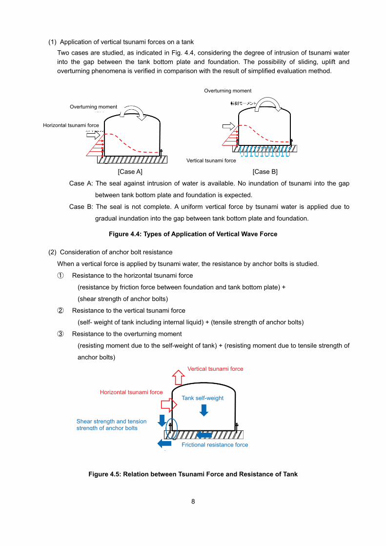
(1) Application of vertical tsunami forces on a tank
Two cases are studied, as indicated in Fig. 4.4, considering the degree of intrusion of tsunami water into the gap between the tank bottom plate and foundation. The possibility of sliding, uplift and overturning phenomena is verified in comparison with the result of simplified evaluation method.
[Case A] [Case B]
Case A: The seal against intrusion of water is available. No inundation of tsunami into the gap
between tank bottom plate and foundation is expected.
Case B: The seal is not complete. A uniform vertical force by tsunami water is applied due to
gradual inundation into the gap between tank bottom plate and foundation.
Figure 4.4: Types of Application of Vertical Wave Force
(2) Consideration of anchor bolt resistance
When a vertical force is applied by tsunami water, the resistance by anchor bolts is studied.
① Resistance to the horizontal tsunami force
(resistance by friction force between foundation and tank bottom plate) +
(shear strength of anchor bolts)
② Resistance to the vertical tsunami force
(self- weight of tank including internal liquid) + (tensile strength of anchor bolts)
③ Resistance to the overturning moment
(resisting moment due to the self-weight of tank) + (resisting moment due to tensile strength of
anchor bolts)
Figure 4.5: Relation between Tsunami Force and Resistance of Tank
Vertical tsunami force
Horizontal tsunami force Tank self-weight
Frictional resistance force
Shear strength and tension strength of anchor bolts
Overturning moment
Overturning moment
Horizontal tsunami force
Vertical tsunami force
9
By utilizing the equation below, the limiting inundation depth at the time when the tank moves by tsunami is calculated.
(𝐹𝑡𝑡 𝐹𝑟𝑡⁄ ) + (𝐹𝑡𝑡 𝐹𝑟𝑡⁄ ) + (𝑀𝑡 𝑀𝑟𝑡⁄ ) = 1
FrH: Horizontal resisting force
FrV: Vertical resisting force
Mt: Resisting moment for overturning
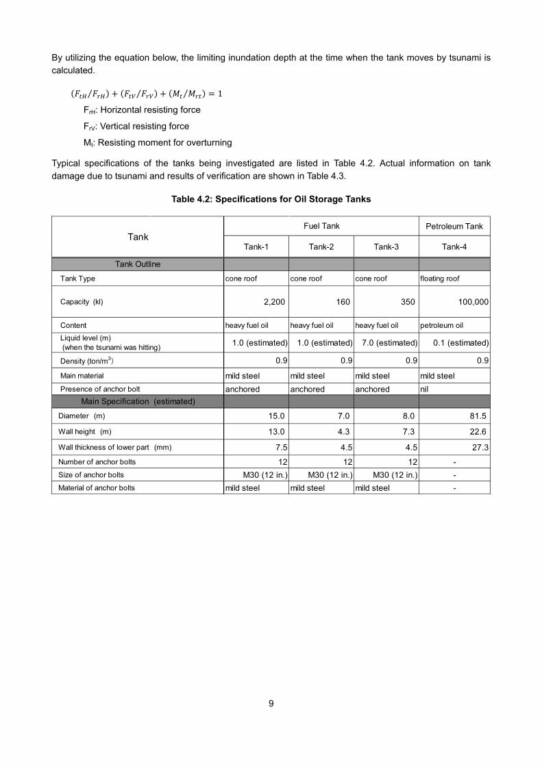
Typical specifications of the tanks being investigated are listed in Table 4.2. Actual information on tank damage due to tsunami and results of verification are shown in Table 4.3.
Table 4.2: Specifications for Oil Storage Tanks
Petroleum Tank
Tank-1 Tank-2 Tank-3 Tank-4
cone roof cone roof cone roof floating roof
2,200 160 350 100,000
heavy fuel oil heavy fuel oil heavy fuel oil petroleum oil
1.0 (estimated) 1.0 (estimated) 7.0 (estimated) 0.1 (estimated)
0.9 0.9 0.9 0.9
mild steel mild steel mild steel mild steelanchored anchored anchored nil
15.0 7.0 8.0 81.5
13.0 4.3 7.3 22.6
7.5 4.5 4.5 27.3
12 12 12 -M30 (12 in.) M30 (12 in.) M30 (12 in.) -
mild steel mild steel mild steel -
Main material
TankFuel Tank
Tank Outline
Tank Type
Capacity (kl)
Content
Liquid level (m) (when the tsunami was hitting)
Density (ton/m3)
Presence of anchor bolt
Main Specification (estimated)
Diameter (m)
Wall height (m)
Wall thickness of lower part (mm)
Number of anchor bolts
Size of anchor bolts
Material of anchor bolts
10
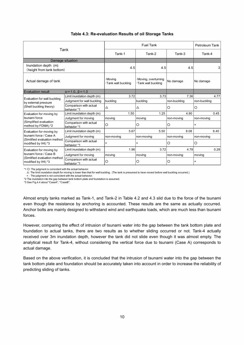
Table 4.3: Re-evaluation Results of oil Storage Tanks
Almost empty tanks marked as Tank-1, and Tank-2 in Table 4.2 and 4.3 slid due to the force of the tsunami even though the resistance by anchoring is accounted. These results are the same as actually occurred. Anchor bolts are mainly designed to withstand wind and earthquake loads, which are much less than tsunami forces.
However, comparing the effect of intrusion of tsunami water into the gap between the tank bottom plate and foundation to actual tanks, there are two results as to whether sliding occurred or not. Tank-4 actually received over 3m inundation depth, however the tank did not slide even though it was almost empty. The analytical result for Tank-4, without considering the vertical force due to tsunami (Case A) corresponds to actual damage.
Based on the above verification, it is concluded that the intrusion of tsunami water into the gap between the tank bottom plate and foundation should be accurately taken into account in order to increase the reliability of predicting sliding of tanks.
Petroleum Tank
Tank-1 Tank-2 Tank-3 Tank-4
4.5 4.5 4.5 3
・Moving・Tank wall buckling
・Moving, overturning・Tank wall buckling No damage No damage
Evaluation result α=1.0、β=1.0Limit inundation depth (m) 3.72 3.73 7.36 4.77Judgment for wall buckling buckling buckling non-buckling non-bucklingComparison with actualbehavior *1 △ △ ○ ○
Limit inundation depth (m) 1.50 1.25 4.90 0.45Judgment for moving moving moving non-moving non-movingComparison with actualbehavior *1 ○ ○ ○ ×
Limit inundation depth (m) 5.67 5.50 8.08 6.40
Judgment for moving non-moving non-moving non-moving non-movingComparison with actualbehavior *1 × × ○ ○
Limit inundation depth (m) 1.96 3.72 4.78 0.28
Judgment for moving moving moving non-moving movingComparison with actualbehavior *1 ○ ○ ○ ×
*1 ○: The judgment is coincident with the actual behavior. △: The limit inundation depth for moving is lower than that for wall buckling. (The tank is presumed to have moved before wall buckling occurred.) × : The judgment is not coincident with the actual behavior.*2 The inundation into the gap between tank bottom plate and foundation is assumed.*3 See Fig.4.4 about "CaseA", "CaseB".
TankFuel Tank
Damage situation
Evaluation for moving bytsunami force / Case B(Simlified evaluation methodmodified by IHI) *3
Evaluation for wall bucklingby external pressure(Shell buckling theory)
Evaluation for moving bytsunami force(Simplified evaluationmethod by FDMA) *2
Evaluation for moving bytsunami force / Case A(Simlified evaluation methodmodified by IHI) *3
Inundation depth (m) (height from tank bottom)
Actual damage of tank
11
5. PREDICTION OF DAMAGE DUE TO TSUNAMI FOR LIQUEFIED GAS STORAGE TANKS
5.1 Parts of Liquefied Gas Storage Tank Were Predicted to be Damaged by Tsunami Force Recently, liquefied gas storage tanks with pre-stressed concrete for the outer tank (outer wall) are mainly constructed in the world. However, this paper specially considers a single containment liquefied gas storage tank with dike because many of these have been constructed in Japan. An example of this tank is shown in Fig. 5.1. These liquefied gas storage tanks have following features, and therefore have excellent safety against tsunamis compared with the cylindrical oil storage tanks.
(1) Most LNG terminals are constructed on the edge of a large bay. Tsunami height does not grow due to area effect of a large bay.
(2) Dikes are placed around each tank as secondary barriers and they have significant strength and height. Therefore, it is presumed that the tsunami will rarely reach the tank.
(3) The tank is fixed to its foundation by anchor straps on the inner tank and anchor bolts on the outer tank. Thus, it would be very difficult to move a tank if a tsunami were to hit the tank.
(4) Even if a tsunami were to flow over the dike and reach the tank, the inner tank, which stores liquefied gas, would not be subjected to the tsunami force because of the double steel wall. In addition, any damage to the outer tank is not directly linked to leakage of liquefied gas.
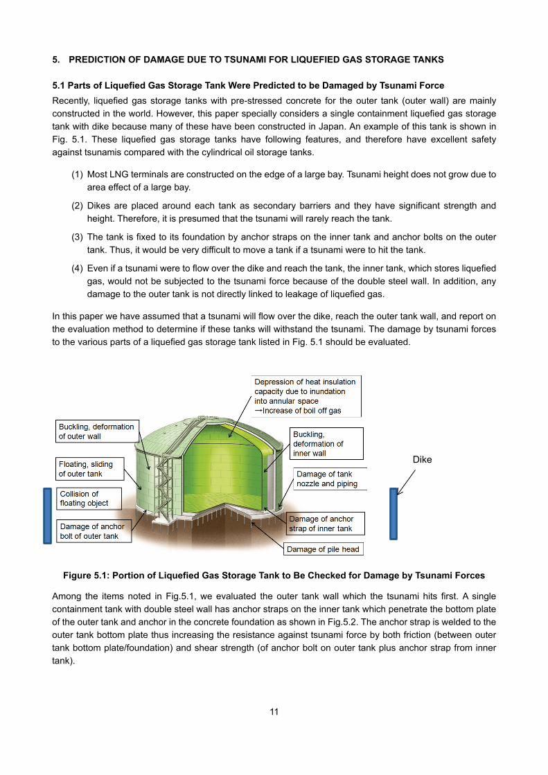
In this paper we have assumed that a tsunami will flow over the dike, reach the outer tank wall, and report on the evaluation method to determine if these tanks will withstand the tsunami. The damage by tsunami forces to the various parts of a liquefied gas storage tank listed in Fig. 5.1 should be evaluated.
Figure 5.1: Portion of Liquefied Gas Storage Tank to Be Checked for Damage by Tsunami Forces
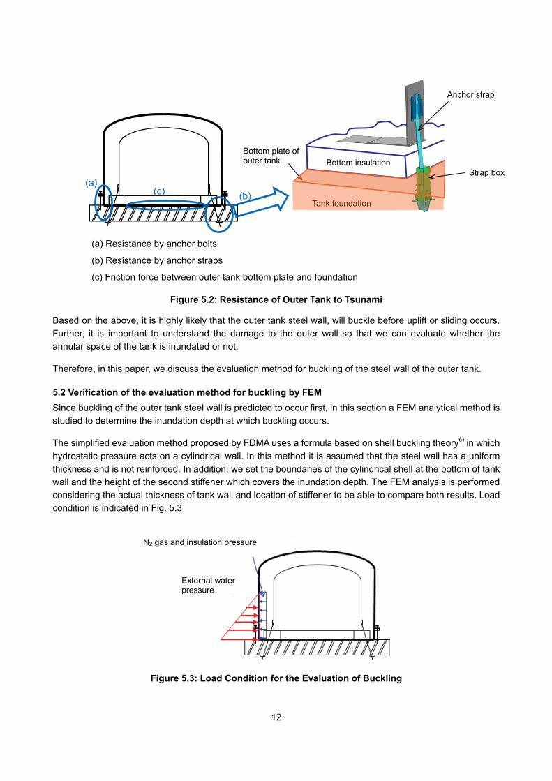
Among the items noted in Fig.5.1, we evaluated the outer tank wall which the tsunami hits first. A single containment tank with double steel wall has anchor straps on the inner tank which penetrate the bottom plate of the outer tank and anchor in the concrete foundation as shown in Fig.5.2. The anchor strap is welded to the outer tank bottom plate thus increasing the resistance against tsunami force by both friction (between outer tank bottom plate/foundation) and shear strength (of anchor bolt on outer tank plus anchor strap from inner tank).
Dike
12
(a) Resistance by anchor bolts
(b) Resistance by anchor straps
(c) Friction force between outer tank bottom plate and foundation
Figure 5.2: Resistance of Outer Tank to Tsunami
Based on the above, it is highly likely that the outer tank steel wall, will buckle before uplift or sliding occurs. Further, it is important to understand the damage to the outer wall so that we can evaluate whether the annular space of the tank is inundated or not.
Therefore, in this paper, we discuss the evaluation method for buckling of the steel wall of the outer tank.
5.2 Verification of the evaluation method for buckling by FEM Since buckling of the outer tank steel wall is predicted to occur first, in this section a FEM analytical method is studied to determine the inundation depth at which buckling occurs.
The simplified evaluation method proposed by FDMA uses a formula based on shell buckling theory6) in which hydrostatic pressure acts on a cylindrical wall. In this method it is assumed that the steel wall has a uniform thickness and is not reinforced. In addition, we set the boundaries of the cylindrical shell at the bottom of tank wall and the height of the second stiffener which covers the inundation depth. The FEM analysis is performed considering the actual thickness of tank wall and location of stiffener to be able to compare both results. Load condition is indicated in Fig. 5.3
Figure 5.3: Load Condition for the Evaluation of Buckling
(a) (b) (c)
Tank foundation
Bottom plate of outer tank
Strap box
Anchor strap
Bottom insulation
External water pressure
N2 gas and insulation pressure
13
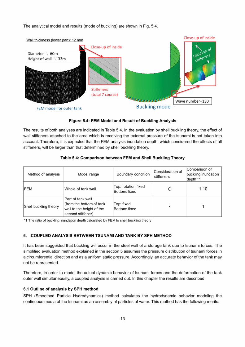
The analytical model and results (mode of buckling) are shown in Fig. 5.4.
Figure 5.4: FEM Model and Result of Buckling Analysis
The results of both analyses are indicated in Table 5.4. In the evaluation by shell buckling theory, the effect of wall stiffeners attached to the area which is receiving the external pressure of the tsunami is not taken into account. Therefore, it is expected that the FEM analysis inundation depth, which considered the effects of all stiffeners, will be larger than that determined by shell buckling theory.
Table 5.4: Comparison between FEM and Shell Buckling Theory
6. COUPLED ANALYSIS BETWEEN TSUNAMI AND TANK BY SPH METHOD
It has been suggested that buckling will occur in the steel wall of a storage tank due to tsunami forces. The simplified evaluation method explained in the section 5 assumes the pressure distribution of tsunami forces in a circumferential direction and as a uniform static pressure. Accordingly, an accurate behavior of the tank may not be represented.
Therefore, in order to model the actual dynamic behavior of tsunami forces and the deformation of the tank outer wall simultaneously, a coupled analysis is carried out. In this chapter the results are described.
6.1 Outline of analysis by SPH method SPH (Smoothed Particle Hydrodynamics) method calculates the hydrodynamic behavior modeling the continuous media of the tsunami as an assembly of particles of water. This method has the following merits:
FEM model for outer tank
Close-up of inside
Stiffeners(total 7 course)
Diameter ≒ 60mHeight of wall ≒ 33m
Buckling modeWave number=130
Close-up of inside
FEM Whole of tank wall Top: rotation fixedBottom: fixed ○ 1.10
Shell buckling theory
Part of tank wall(from the bottom of tankwall to the height of thesecond stiffener)
Top: fixedBottom: fixed × 1
*1 The ratio of buckling inundation depth calculated by FEM to shell buckling theory
Comparison ofbuckling inundationdepth *1
Method of analysis Model range Boundary conditionConsideration ofstiffeners
Wall thickness (lower part): 12 mm
14
(1) It is easy to build the complicated shape model of a tsunami because the mesh required in FEM analysis is not necessary.
(2) The behavior of the tsunami with large shape deformations can be expressed.
The following studies are carried out in order to confirm the effectiveness of the SPH method for a coupled analysis of tsunami and tank.
(1) Comparison with hydraulic model experiment
(2) Application of SPH method on actual LNG tank
Program of PAM-CRASH2G V2009.0 is used.
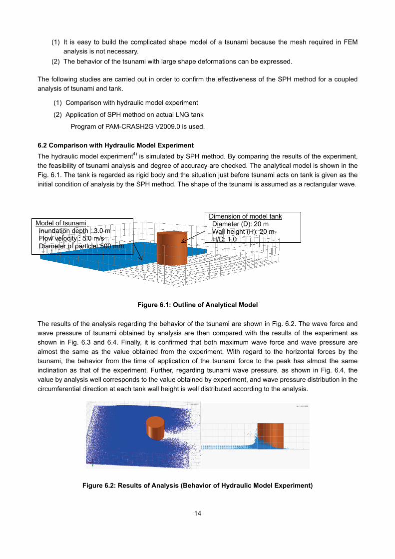
6.2 Comparison with Hydraulic Model Experiment The hydraulic model experiment4) is simulated by SPH method. By comparing the results of the experiment, the feasibility of tsunami analysis and degree of accuracy are checked. The analytical model is shown in the Fig. 6.1. The tank is regarded as rigid body and the situation just before tsunami acts on tank is given as the initial condition of analysis by the SPH method. The shape of the tsunami is assumed as a rectangular wave.
Figure 6.1: Outline of Analytical Model
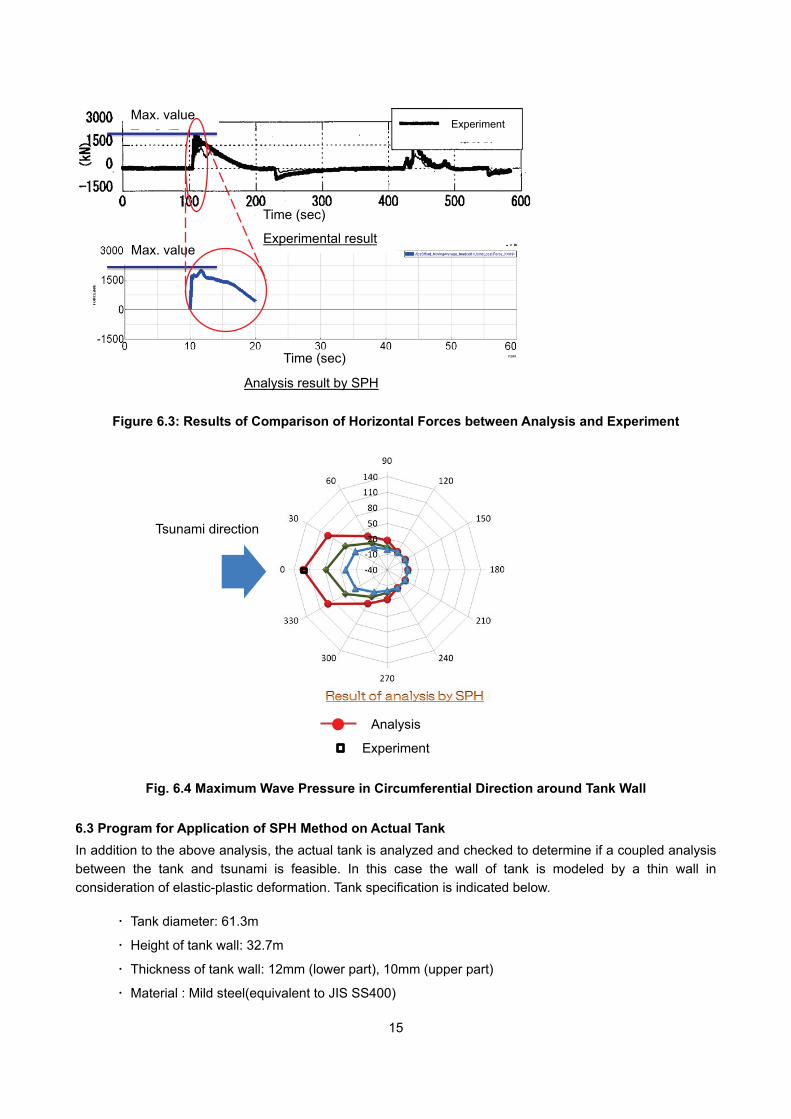
The results of the analysis regarding the behavior of the tsunami are shown in Fig. 6.2. The wave force and wave pressure of tsunami obtained by analysis are then compared with the results of the experiment as shown in Fig. 6.3 and 6.4. Finally, it is confirmed that both maximum wave force and wave pressure are almost the same as the value obtained from the experiment. With regard to the horizontal forces by the tsunami, the behavior from the time of application of the tsunami force to the peak has almost the same inclination as that of the experiment. Further, regarding tsunami wave pressure, as shown in Fig. 6.4, the value by analysis well corresponds to the value obtained by experiment, and wave pressure distribution in the circumferential direction at each tank wall height is well distributed according to the analysis.
Figure 6.2: Results of Analysis (Behavior of Hydraulic Model Experiment)
Model of tsunami Inundation depth : 3.0 m Flow velocity : 5.0 m/s Diameter of particle: 500 mm
Dimension of model tank Diameter (D): 20 m Wall height (H): 20 m
H/D: 1.0
15
Figure 6.3: Results of Comparison of Horizontal Forces between Analysis and Experiment
Analysis
Experiment
Fig. 6.4 Maximum Wave Pressure in Circumferential Direction around Tank Wall
6.3 Program for Application of SPH Method on Actual Tank In addition to the above analysis, the actual tank is analyzed and checked to determine if a coupled analysis between the tank and tsunami is feasible. In this case the wall of tank is modeled by a thin wall in consideration of elastic-plastic deformation. Tank specification is indicated below.
・ Tank diameter: 61.3m
・ Height of tank wall: 32.7m
・ Thickness of tank wall: 12mm (lower part), 10mm (upper part)
・ Material : Mild steel(equivalent to JIS SS400)
Time (sec)
Experimental result
Time (sec)
Analysis result by SPH
Max. value
Max. value
Tsunami direction
Experiment
16
Yield strength: 235N/mm2
Modulus of longitudinal elasticity: 203000N/mm2
Modeling of the tsunami is as follows. In this analysis a greater than expected tsunami flow velocity was given in order to simulate the phenomena of tank wall buckling.
・ Inundation depth of tsunami :5m
・ Speed of tsunami :8.33m/s
・ Size of SPH : 500mm
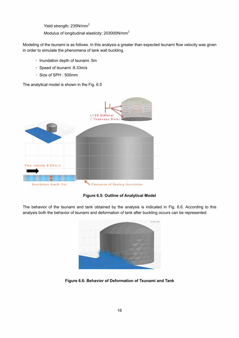
The analytical model is shown in the Fig. 6.5
Figure 6.5: Outline of Analytical Model
The behavior of the tsunami and tank obtained by the analysis is indicated in Fig. 6.6. According to this analysis both the behavior of tsunami and deformation of tank after buckling occurs can be represented.
Figure 6.6: Behavior of Deformation of Tsunami and Tank
Flow velocity: 8 .3 3 m /s
In u n d a tion d ep th : 5 m Clea ra n ce o f f lo a tin g fou n d a tion
L1 3 0 Stif fen er( Th ickn ess: 9 m m )
17
7. CONCLUSION
In order to establish a method to evaluate the structural integrity of flat bottom cylindrical tanks against a tsunami, the conventional simplified evaluation method is checked in view of proper method and issues brought by this study. Followings are the results.
(1) The simplified evaluation method for estimating damage to oil storage tanks finds that tanks without anchor bolts and tanks with weak anchors were easily damaged due to horizontal and vertical movement. This result roughly matches with actual damage.
(2) In cases where tsunami water does not enter the gap between the tank bottom plate and foundation, sometimes the results of the simplified evaluation method by FDMA does not correspond to actual damages. Therefore, in order to increase the reliability of predicting the possibility of tank sliding, it is important to take into account the intrusion of tsunami water into this space accurately.
(3) For the case of a liquefied gas storage tank with a dike, it is considered that they have excellent safety against a tsunami compared with cylindrical oil storage tanks because of their structural features and site condition. If a tsunami flows over the dike and reaches the tank, the buckling of the outer steel wall by tsunami force could occur before other damages. FEM analysis is carried out to establish the evaluation method of buckling of the outer steel wall and is validated by comparing with shell buckling theory.
(4) The SPH method is adopted as an analytical tool which can represent both hydrodynamic behavior of tsunami and deformation of tank wall at the same time. A coupled analysis between tsunami and tank is performed by using two kinds of models. The following results are obtained.
○1 In the SPH analysis comparing the results with the hydraulic model experiment, the wave force and pressure measured in the experiment are well represented.
○2 In the SPH analysis for an actual tank, the hydrodynamic behavior of the tsunami and the buckling behavior of tank wall can be represented accurately.
These results show that the SPH method can be used to check the structural integrity of tanks against tsunami forces.
Furthermore, issues to be considered to improve the accuracy of analysis are described below.
(1) Establishment of how to determine the vertical wave force (buoyancy) corresponding to the degree of intrusion of water into the gap between tank bottom and foundation.
(2) Establishment of how to determine an accurate initial condition of the tsunami for analysis (tsunami height just before tsunami acts on the tank, distribution of velocity )
(3) Establishment of how to evaluate whether tsunami water will enter the space between outer and inner wall in relation to the degree of buckling and stresses occurring in the outer steel wall.
(4) Study of evaluation method which takes into account the effect of a dike.
ACKNOWLEDGMENT
We appreciate the cooperation of National Research Institute of Fire and Disaster and ESI Japan, Ltd. in this study.
18
REFERENCES
1) “The report of expert panel regarding the seismic and tsunami countermeasures learned by the 2011 Tohoku Earthquake”, Central Disaster Prevention Council, (2011.9). (in Japanese)
2) K. Hatakeyama: “The damages of oil storage tank caused by tsunami”, 15th Lecture meeting of research for fire safety and disaster prevention, National Research Institute of Fire and Disaster, (2012.1). (in Japanese)
3) “2011 The report of the damages by 2011 Tohoku Earthquake and fire-fighting operation (1st Report)”, Document of National Research Institute of Fire and Disaster, vol.82, (2011.12) (in Japanese)
4) “The report of research and examination regarding the countermeasures of tsunami and inundation for facilities of hazardous material “, The Fire and Disaster Management Agency of Japan, (2009.3). (in Japanese)
5) Cabinet Office: “The prediction of tsunami height, inundation area (2nd report), and damages (1st report) by the big earthquake along Nankai trough”, The press release of Cabinet Office, document 1-1, (2012.8). (in Japanese)
6) “The handbook for vibration and buckling of shell structure”, The Japan Society of Mechanical Engineers, Gihodo shuppan,(2003), (in Japanese)