dampers for earthquake vibration control -...
TRANSCRIPT
Dampers for Earthquake Vibration Control
Dr. Imad H. Mualla*
DAMPTECH Co., Ltd.
Denmark
ABSTRACT
This paper presents the development, testing and application of a novel, worldwide patented friction damper system developed by (
*) in order to control
the vibration in structures and buildings due to earthquakes or strong winds. The capability of the dampers to dissipate energy has been extensively studied and tested in previous research both experimentally and numerically, as well as in several finalized projects around the world.
This paper also presents a study on the parameters that govern the perfor-mance of a friction damping system for base isolation of structures. The device is designed to dissipate seismic input energy and protect buildings from struc-tural and nonstructural damage during strong vibration.
The dampers have been tested at the Technical University of Denmark (DTU) and in experimental tests at Takenaka Corporation Research Center in Japan. The comparison of results obtained from these experimental and numerical models shows good agreement.
A study of the response for static and dynamic loading has identified the pa-rameters which influence the response of a structure improved with the damp-ing system. The numerical studies have demonstrated that the overall response is mainly affected by damper properties such as geometry, frictional sliding moment and the structural natural frequencies.
Different damper systems are presented in this work. The dampers described are mainly used for vibration control of structures and base isolation of struc-tures.
The Damptech damper devices are easy to manufacture and implement in structures. The dampers are economical to manufacture due to the selection of material and its availability. In the unlikely situation of damage to a damper, it can easily be replaced or readjusted.
The dampers have been installed in several buildings in Japan, Greece, India and Denmark.
*Corresponding Author;
Dr. Imad H. Mualla, Chief Technical Officer of DAMPTECH, DTU-B.118,2800 Lyngby, Denmark. Tel. +45 4525 1725, Fax+45 4588 3282 Email: [email protected] Web: www.damptech.com

INTRODUCTION
Seismic isolation of a structure reduces the transfer to the structure of ground motion produced by an earthquake. Seismic isolation is typically obtained by a damping sys-tem acting as base isolation between the structure and the ground. Such damping sys-tems are designed to protect structural integrity and prevent damages and injuries to the occupants by reducing seismic forces and deformations in the structure, Housner et al. (1997).
Several types of base isolation systems have been proposed and investigated; see e.g. (Skinner et al. 1993, Chopra 1995). The number of projects with such systems is increasing in different places around the world and the base isolation systems have proved their value through many earthquakes.
Friction dampers are often an essential component of these base isolation systems because they represent a high energy dissipation potential at low cost and are easy to install and maintain. Several friction devices have been tested experimentally, see (Ai-ken & Kelly 1990, Constantinou at al. 1991), and some of these have been imple-mented in buildings around the world. Also viscoelastic dampers are often used in base isolation systems, see e.g. Kelly (1999).
The present paper concerns the development of a new rather inexpensive friction-viscoelastic damper and its application in a damping system for base isolation of a structure. The damper can easily be manufactured and installed in a short time. The friction version of the damper has been installed in several buildings in Japan. In the following a computational model is set up for the mechanical behavior of the damper. This model is combined with another computational modeling of the damping system and the structure loaded by an earthquake. Next this model is used for determination of essential structural design quantities as a function of earthquake intensity.
Several models and applications of new damping systems will also be presented.
DAMPING SYSTEM
The friction damper (FD), see Figure 1a and 1b, consists of two rigid plates HG and HB connected in the rotational hinge H. The moment-rotation behavior in H is elastic-frictional. When the damper is used for base isolation of a structure, the two other plate end points – the connection points - are moment free connected to ground (G) and structural base (B). When the distance between the connection points changes, the angle between the damper plates will change in the hinge H. The damper dissi-pates energy if the elastic rotation limit is exceeded, i.e. if sliding occurs in the hinge.
Extending the friction damper, as AFV in Figure 6, with another plate VC connected to AFV in the viscoelastic rotational hinge V, results in the friction-viscoelastic damper (FVD) considered in this paper.
a) b) b) Figure 1. a) Friction damper, b) Experimental setup at DTU Denmark for the friction damper

An example on application of FDs or FVDs in a damping system for horizontal base
isolation of a structure is shown in Figure 2a, where eight identical dampers are in-serted between the structural base PQRS and the ground. One connection point of each damper is connected the structural base in a point B and the other connection point to the ground in a point G. The dampers are used in pairs to obtain symmetric behavior of the damper pair. Four pairs are used in the damping system to obtain symmetric behavior and to obtain damping resistance against both the two translation components in the horizontal plane (x,y-plane) and the rotation about the vertical axis (z-axis). Many other arrangements are possible, e.g. a three damper pair arrangement along the sides of a triangle.
FRICTION DAMPER TESTS
A large capacity friction damper (force capacity 120 kN) was built and tested at DTU in a 250 kN Instron machine as shown in Figure 1b. Loads with different frequencies and displacement amplitudes were applied. The test results indicates a stable performance over many cycles as shown in Figure 2b for 100 cycles with the frequency 0.5 Hz and the displacement amplitude 25 mm. This good performance is owing to the use of a special friction pad material between the damper plates in the frictional hinge. Further investigations support this conclusion (Mualla 2000a, Mualla 2000b, Mualla et al. 2002)
Another case is the friction dampers for a new 5-storey RC laboratory building in Ja-pan; see Figure 3, in which 8 dampers were installed in the basement as base isolation Figure 4. Tests were conducted; see Figure 5a, through a hydraulic actuator with a ca-pacity 500kN, stroke 1016 mm and a force transducer with maximum load of 500kN as follows:
− 50 mm amplitude to adjust clamping force to get required slip force
− 300 mm amplitude to inspect period dependency
− 480 mm displacement
− 480 mm amplitude to confirm the limit displacement
− 300 mm amplitude to inspect direction dependency The required capacity for the dampers was achieved. Beside these tests other tests
were conducted on a scaled model with different temperatures to evaluate the dam-per’s temperature independence.
a) b)
Figure 2. a) Double symmetric 8 damper system of FDs or FVDs. Each damper connects ground (G) and base (B), b) Experimental displacement cycle test of friction damper.

Figure 3. Building base isolated with friction dampers.
Figure 4. Layout of damper locations at base of building.
a) b)
Figure 5. a) Experimental tests of friction damper at Takenaka Research Center, Japan, b) The friction damper after installation in the building base.

MODELING
1.1 Friction-viscoelastic damper
The friction-viscoelastic damper with two energy-dissipating hinges Figure 6 consists of three rigid plates AF (length a), FV (length b) and VC (length c) connected in a fric-tional hinge F with the mutual angle vf between the connected plates and in a viscoe-lastic hinge V with the mutual angle vv (subscripts f and v for frictional respectively vis-coelastic). When the length d of the damper, i.e. the distance between the connection points A and C increases u from the undeformed value d0, the angles between the damper plates increase θf and θv in point F respectively V.
The moment-rotation (Mf-θf) behavior in the frictional hinge is elastic-frictional as shown in Figure 7a with an elastic stiffness kf and the sliding moment Msf, i.e.
otherwisekM
MandMMabsforM
fff
ffsfff
θ
θ&&
&&
=
>== 0)(0 (1)
where a dot over a symbol means differentiation dt
d with respect to time t.
The moment-rotation (Mv-θv) behavior in the viscoelastic hinge is fractional viscoe-lastic, i.e.
))()(()()( tDbtktMDatM vvvvvvv θθ αα +=+ (2)
where α,,, vvv bak are material constants and where the fractional derivative of a time
dependent variable )(ty is defined with Equation 3, see e.g. Koh & Kelly (1990).
∫ −−Γ=
t
dt
y
dt
dtyD
0)(
)(
)1(
1)( ζ
ζζ
α αα
(3)
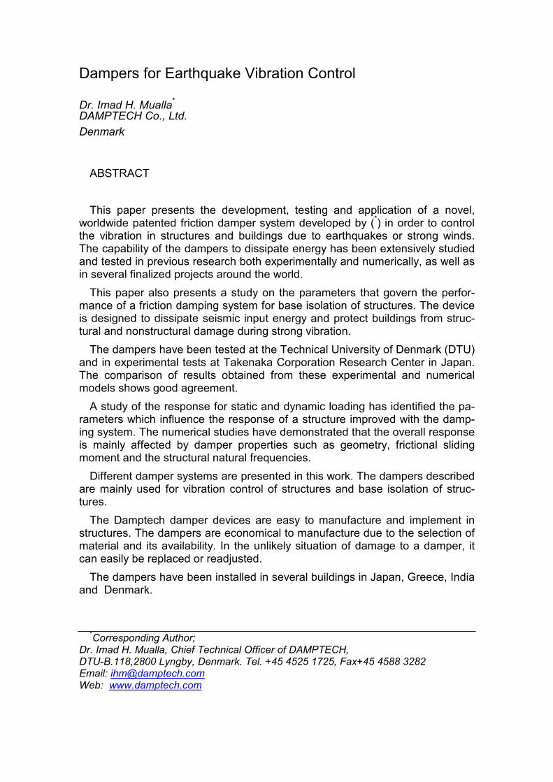
The harmonic behavior of the fractional viscoelastic material is illustrated in Figure 7b.
Figure 6. Geometry and notation for friction-viscoelastic damper.
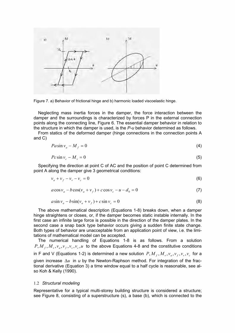
Figure 7. a) Behavior of frictional hinge and b) harmonic loaded viscoelastic hinge.
Neglecting mass inertia forces in the damper, the force interaction between the damper and the surroundings is characterized by forces P in the external connection points along the connecting line, Figure 6. The essential damper behavior in relation to the structure in which the damper is used, is the P-u behavior determined as follows.
From statics of the deformed damper (hinge connections in the connection points A and C)
0sin =− fa MvPa (4)
0sin =− vc MvPc (5)
Specifying the direction at point C of AC and the position of point C determined from point A along the damper give 3 geometrical conditions:
0=−−+ cvfa vvvv (6)
0cos)cos(cos 0 =−−++− duvcvvbva cfaa (7)
0sin)sin(sin =++− cfaa vcvvbva (8)
The above mathematical description (Equations 1-8) breaks down, when a damper hinge straightens or closes, or, if the damper becomes static instable internally. In the first case an infinite large force is possible in the direction of the damper plates. In the second case a snap back type behavior occurs giving a sudden finite state change. Both types of behavior are unacceptable from an application point of view, i.e. the limi-tations of mathematical model can be accepted.
The numerical handling of Equations 1-8 is as follows. From a solution
uvvvvMMP cvfavf ,,,,,,, to the above Equations 4-8 and the constitutive conditions
in F and V (Equations 1-2) is determined a new solution cvfavf vvvvMMP ,,,,,, for a
given increase u∆ in u by the Newton-Raphson method. For integration of the frac-
tional derivative (Equation 3) a time window equal to a half cycle is reasonable, see al-so Koh & Kelly (1990).
1.2 Structural modeling
Representative for a typical multi-storey building structure is considered a structure; see Figure 8, consisting of a superstructure (s), a base (b), which is connected to the
ground (g) through supports for vertical load, and an isolation system for horizontal loads. The isolation system is made of FVDs and an auxiliary system (a) connecting base and ground. The dampers are arranged as shown in Figure 2a.
A vertical shear beam with torsion about the beam axis (z-axis) is used as structural model. The shear beam end nodes are located with node 1 in the base and node 2 in the superstructure. In each node 3 degrees of freedom (dof) exist: the translations ux,uy in the horizontal x,y-plane and the rotation rz about the z-axis.
Figure 8. Structure with isolation system.
Using a first order mechanical theory for the structure except the FVDs, which are
handled exact as described in section 4.1, the notation in the following is as follows. M
is a mass matrix, C a viscous damping matrix, K a stiffness matrix and V a dof-vector.
A subscript on these quantities specifies the related structural unit, e.g. Ms is the mass
matrix for the superstructure and K the stiffness matrix for the total system (super-structure + base + isolation system).
The natural vibration problem (periods Ts) for the superstructure (with fixed base) has some importance as reference. It is governed by:
0=++ ssssss VKVCVM &&& (9)
where ][ zsysxs
T
s ruu=V .
Assuming that the damping in the superstructure is connected to the superstructure
deformation and not its rigid body motion and neglecting the mass of the isolation sys-tem, the equations for the dynamic behavior of the total system can be formulated as
++
+=++
00
gagad VKVCFRKVVCVM
&&&& (10)
where
][][ zsysxszbybxb
T
s
T
b
T ruuruu== VVV (11)
=
s
b
M
MM
0
0 (12)
−
−+=
ss
sas
CC
CCCC (13)
−
−+=
ss
sas
KK
KKKK (14)
R - external load vector
Fd - load vector from the forces on the base from all FVDs
with the horizontal ground motion
][ zgygxg
T
g ruu=V (15)
With a prescribed ground motion it is appropriate to introduce relative displacements
Vr of the system defined as the displacements beyond a rigid body motion V
g of the
system following the ground motion, i.e.
grVVV −= (16)
][ T
g
T
g
gTVVV = (17)
Inserting Equation 16 in Equation 10 modifies the governing equation to
gdrrrVM
FRKVVCVM &&&&& −
+=++0
(18)
because the internal forces are independent of a rigid body motion of the system.
In the following the ground motion represents an earthquake and the structural be-
havior )(tV for 0>t is determined from Equation 18 and the initial conditions
0)0()0( == VV & corresponding to a structure initially at rest.
The Equation 18 with initial conditions is integrated numerically in time by the central difference method. The time step ∆t is typically chosen to 0.01 sec. Then the load from the ground acceleration in Equation 17 typically specified per 0.02 sec and interpolated linearly in each intermediate interval is handled reasonably. Moreover the numerical stability of Equation 18 is secured, because the natural structural periods typically are much larger than ∆t. Finally the transition between elastic and sliding behavior in the damper is handled sufficiently accurate without special precautions. Of course, halving the time step does not change the computational results essentially.
STRUCTURAL RESPONSE
The structure Figure 8 with isolation system Figure 2a is loaded by horizontal ground accelerations in the x-direction corresponding to an earthquake acceleration compo-nent (El-Centro with max acceleration 0.35g (g = gravity)) and some aspects of the
structural response are studied. In the FVDs cba == 2/ and in the un-deformed state 060|||||||| ==== cvfa vvvv . The elastic stiffness kf of the frictional hinge is great com-
pared with the elastic stiffness kv of the viscoelastic hinge. The viscoelastic properties

in the FVDs are determined by 243.0,07.13,14.0 === αvv ba see (4.2). For the su-
perstructure the un-damped period is sec1=sT and the viscous damping ratio
02.0=sζ . The superstructure mass m is equal to the base mass. No auxiliary damp-
ing system is used, i.e. 0== aa CK .
The damper system is designed according to the following principles, which for sim-plicity are applied to closed dampers (both frictional hinge and the viscoelastic hinge closed).
The horizontal sliding load is equal to a specified part (rhor) of the structural weight, i.e.
a
Mnmgr
sf
achor =2 (19)
where the number of contributing dampers 4=acn (initially only damper 1-4 gives re-
sistance). Here is considered 3.0,15.0=horr the low respectively the high resistant
system. A value is specified for the small vibration period Tb of the rigid structure with isola-
tion system, i.e.
m
akn
T
veffac
b 2
/)
2(
2
2 =π
(20)
where kveff is the effective stiffness in the viscoelastic hinge at harmonic vibrations with
period Tb. Here is considered sec2=bT . Then a time window for integration of the vis-
coelastic material equal to 2sec is sufficiently. In order to obtain a certain balance between the frictional part and the viscoelastic
part of the FVD, the sliding moment Msf has to be reached in the viscoelastic hinge for
a specified angle change vsθ in the viscoelastic hinge at a harmonic vibration with pe-
riod Tb, i.e.
vsveffsf kM θ= (21)
Here is chosen 020=vsθ .
For the two above defined designs (Equations 19-21) gives ma 427.0= in the low
resistant system and ma 854.0= in the high resistant system. These two designs are
investigated below. To illustrate the behavior of the symmetric 8 damper system, the high resistant ver-
sion is subjected to a slow (no inertia forces, no time effects in viscoelastic hinges) 5/4 displacement cycle in the x-direction (with no time effects is kv changed to kveff in this slow cycle case). The resultant force component P in the displacement direction in the damping system is shown as function of the displacement u in Figure 9a. Each slope discontinuity on the P-u curve corresponds to a phase shift in one or more dampers
(elastic → sliding or reverse). With 1/ =sfMPa as an approximate measure for the
sliding strength of a single damper, the non-dimensional loads 4-5 at first (sliding in elongating dampers 1,3) and second (also sliding in shortening dampers 2,4) slope discontinuity are easily understood.
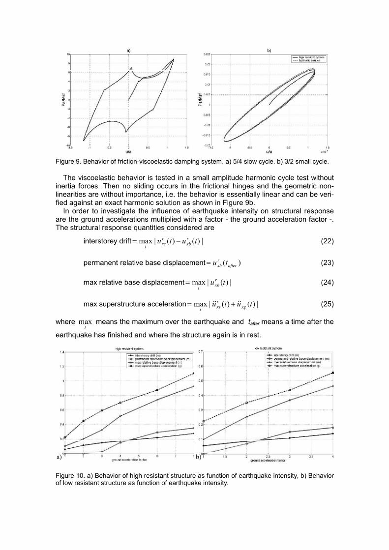
Figure 9. Behavior of friction-viscoelastic damping system. a) 5/4 slow cycle. b) 3/2 small cycle.
The viscoelastic behavior is tested in a small amplitude harmonic cycle test without
inertia forces. Then no sliding occurs in the frictional hinges and the geometric non-linearities are without importance, i.e. the behavior is essentially linear and can be veri-fied against an exact harmonic solution as shown in Figure 9b.
In order to investigate the influence of earthquake intensity on structural response are the ground accelerations multiplied with a factor - the ground acceleration factor -. The structural response quantities considered are
interstorey drift |)()(|max tutu r
xb
r
xst
−= (22)
permanent relative base displacement )( afterr
xb tu= (23)
max relative base displacement |)(|max tu rxbt
= (24)
max superstructure acceleration |)()(|max tutu xg
r
xst
&&&& += (25)
where tmax means the maximum over the earthquake and tafter means a time after the
earthquake has finished and where the structure again is in rest.
a) b)
Figure 10. a) Behavior of high resistant structure as function of earthquake intensity, b) Behavior of low resistant structure as function of earthquake intensity.
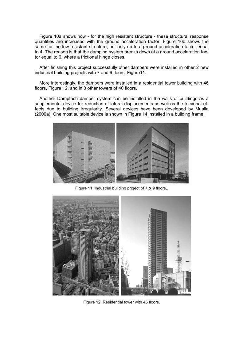
Figure 10a shows how - for the high resistant structure - these structural response
quantities are increased with the ground acceleration factor. Figure 10b shows the same for the low resistant structure, but only up to a ground acceleration factor equal to 4. The reason is that the damping system breaks down at a ground acceleration fac-tor equal to 6, where a frictional hinge closes.
After finishing this project successfully other dampers were installed in other 2 new
industrial building projects with 7 and 9 floors, Figure11. More interestingly, the dampers were installed in a residential tower building with 46
floors, Figure 12, and in 3 other towers of 40 floors. Another Damptech damper system can be installed in the walls of buildings as a
supplemental device for reduction of lateral displacements as well as the torsional ef-fects due to building irregularity. Several devices have been developed by Mualla (2000a). One most suitable device is shown in Figure 14 installed in a building frame.
Figure 11. Industrial building project of 7 & 9 floors,.
Figure 12. Residential tower with 46 floors.

Figure 13. Three New Towers of 40 floors.
Figure 14. V-Bracing with 2 units of a multi unit damper
The dampers are simple to manufacture and install. Depending on the actual appli-cation a damper may contain many frictional joints. Figure 15a shows a version with 4 multi unit friction joints in both the upper and lower part of the damper. With 7 layers of steel plates, there are in total 48 frictional joints.
This model had been tested intensively at DTU in a 5000 kN Instron machine as shown in Figure 15b.
A large capacity can be achieved with this model. Figure 16 shows the hysteresis loops with a capacity of nearly 1000 kN. By simply applying more tension force in the 8 bolts, 1480 kN have been achieved. It is worth mentioning that more capacity can be obtained by simply increasing the number of bolts and/or the number of plate layers.

a) b)
Figure 15. a) Multi unit damper with several layers of plates, b) Testing of multi unit damper by 5000 kN Instron machine.
Force-Displacement
-1500
-1000
-500
0
500
1000
1500
-40 -30 -20 -10 0 10 20 30 40
Disp. mm
Force kN
Figure 16. Force-displacement relationship
There are other applications by different damping systems. Figure 17a shows a
damper device with invert V-Bracing system that was installed in an industrial building within 2 days without interfering in the daily operation in the power plant. One day to prepare the connections and another day to install the damper.
This solution is very practical and economical to factories, industries and power plants.
For prefab structures the damper device can also be useful and improve the beam-column joint as shown in Figure 17b.
Shear walls are normally used to provide the lateral resistance. However, the deme-rit of using shear walls is that they increase the acceleration especially at the upper floors causing substantial damages inside the building or house. Consequently it is recommended to increase damping. Figure 18a shows a Panel Damper that is appli-cable in most building types.
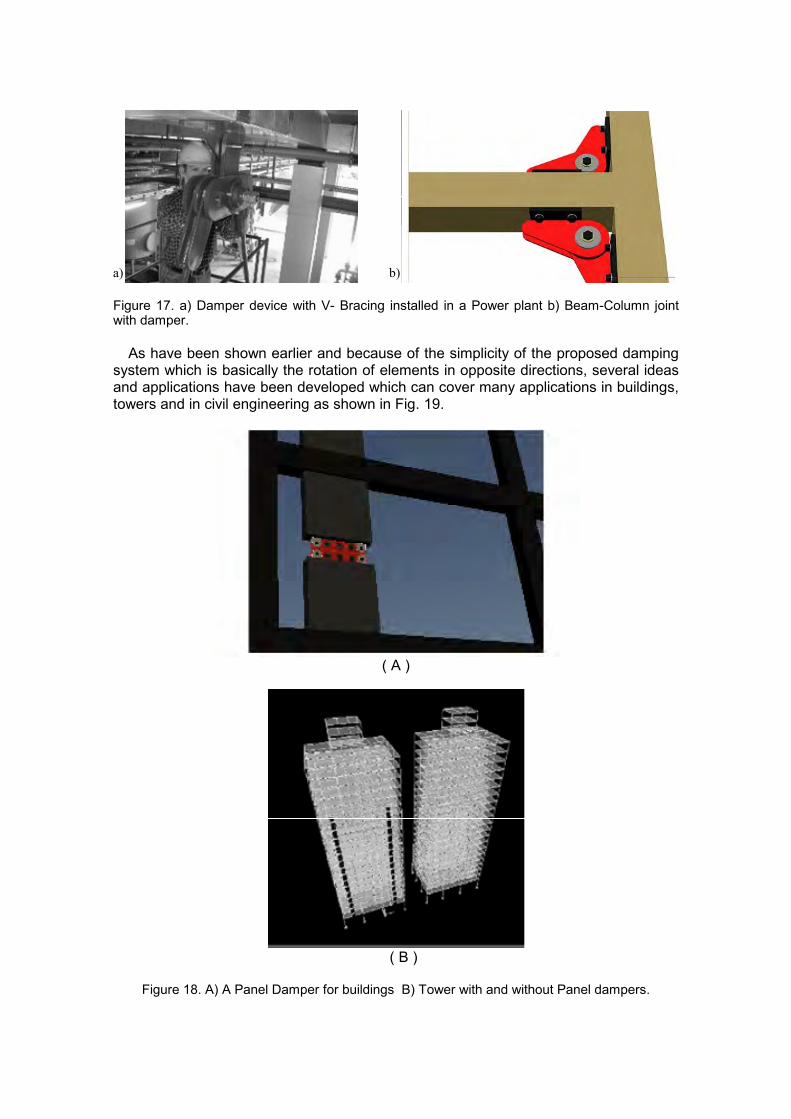
a) b) Figure 17. a) Damper device with V- Bracing installed in a Power plant b) Beam-Column joint with damper.
As have been shown earlier and because of the simplicity of the proposed damping
system which is basically the rotation of elements in opposite directions, several ideas and applications have been developed which can cover many applications in buildings, towers and in civil engineering as shown in Fig. 19.
( A )
( B )
Figure 18. A) A Panel Damper for buildings B) Tower with and without Panel dampers.
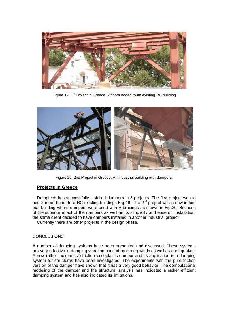
Figure 19. 1st Project in Greece. 2 floors added to an existing RC building
Figure 20. 2nd Project in Greece. An industrial building with dampers.
Projects in Greece
Damptech has successfully installed dampers in 3 projects. The first project was to
add 2 more floors to a RC existing buildings Fig 19. The 2nd project was a new indus-
trial building where dampers were used with V-bracings as shown in Fig.20. Because of the superior effect of the dampers as well as its simplicity and ease of installation, the same client decided to have dampers installed in another industrial project.
Currently there are other projects in the design phase.
CONCLUSIONS
A number of damping systems have been presented and discussed. These systems are very effective in damping vibration caused by strong winds as well as earthquakes. A new rather inexpensive friction-viscoelastic damper and its application in a damping system for structures have been investigated. The experiments with the pure friction version of the damper have shown that it has a very good behavior. The computational modeling of the damper and the structural analysis has indicated a rather efficient damping system and has also indicated its limitations.

The device is easy to manufacture and implement in structures. It is an economic de-vice due to material availability. It can easily be replaced if damaged, which is unlikely, and it can easily be readjusted after use. Several Damptech damping systems have been installed in projects in Japan, Greece, India and Denmark.
REFERENCES
Aiken, I.D. & Kelly, J.M. 1990. Earthquake simulator testing and analytical studies of two energy-absorbing systems for multistory structures. Report No. UCB/EERC-90-03, University of Cali-fornia, Berkeley.
Chopra, A K. (ed.) 1995. Dynamics of Structures. USA: Prentice-Hall. Constantinou, M.C., Reinhorn, A.M., Mokha, A.S. and Watson, R. 1991 Displacement control
device for base-isolated bridges. Earthquake Spectra 7(2):179-200. Housner, G.W., Bregman, L.A., Caughey, T.K., Chassiakos, A.G., Claus, R.O. and Masri S.F.
1997. Structural control: Past, present and future. Journal of Engineering Mechanics 123(9): 897-971.
Kelly, J.M. 1999. The role of damping in seismic isolation. Earthquake Engng. Struct. Dyn 28:3-20.
Koh, C.G & Kelly, J.M. 1990 Application of Fractional Derivatives to Seismic Analysis of Base-Isolated Models. Earthquake Engng. Struct. Dyn. 19:229-241.
Skinner, R.I., Robinson, W.H. and McVerry, G.H. (eds.) 1993. An Introduction to Seismic Isola-tion. England: John Wiley & Sons.
Mualla, I.H. 2000a. Experimental Evaluation of a New Friction Damper Device, 12th World Con-
ference on Earthquake Engineering, Auckland, New Zealand. Mualla, I.H. 2000b. Parameters Influencing the Behavior of a New Friction Damper Device.
SPIE’s 7th International Symposium on Smart Structures & Materials, SS2000, CA, USA,
2000. Mualla, I.H., Nielsen, L.O., Belev, B., Liao, W.I., Loh, C.H., Agrawal, A. 2002. Performance of
Friction-Damped Frame Structure: Shaking Table Testing and Numerical Simulations. 7th U.S.
National Conference on Earthquake Engineering, Boston, USA. Nielsen, L.O., Mualla, I.H. and Iwai, Y. 2004. Seismic isolation with a new friction-viscoelastic
damping system. 13th World Conference on Earthquake Engineering.