danger - schneider electric · danger indicates an imminently hazardous situation which, ... from...
TRANSCRIPT

EAV72497-03 1/4
96.03.78
96.03.78
PM1200EasyLogicTM
8.00.31
90.03.54
83.03.26
Safety precautions
DANGERHAZARD OF ELECTRIC SHOCK, EXPLOSION, OR ARC FLASH• Apply appropriate personal protective equipment (PPE) and follow safe
electrical work practices. • Turn off all power supplying this device and the equipment in which it is
installed before working on the device or equipment.• Always use a properly rated voltage sensing device to confirm that all
power is off.• Do not exceed the device’s ratings for maximum limits.• Do not use this device for critical control or protection applications where
human or equipment safety relies on the operation of the control circuit.• Never short the secondary of a voltage transformer (VT).• Never open circuit a current transformer (CT).• Always use grounded external CTs for current inputs.Failure to follow these instructions will result in death or serious injury.
1
3
2
1. Turn off all power supplying this device and the equipment in which it is installed before working on the device or equipment.
2. Always use a properly rated voltage sensing device to confirm that all power is off.
Model Wiring POP Class 0.5 Class1
DM5230 3PH3W
DM5240 1PH/3PH4W
25(0.98)
28(1
.10)
PM1200EasyLogicTM
PM1200EasyLogicTM
PM1200EasyLogicTM
Minimum clearance between mountedmeters
Conzerv DM5200 series electronic energy meter
Offers direct measurement of energy consumption (no external multipli-cation factor required).The energy meter has six digit moving counters and three static or fixed zeros.
mm(in)
To download other documentation, visitwww.schneider-electric.co.in. Type DM5200 in the search field.
Box contents
Dimensions
Conzerv DM5230/DM5240
TEST AND CALIBRATION CERTIFICATE
EAV72497-03
EAV72497-03 2/4
`
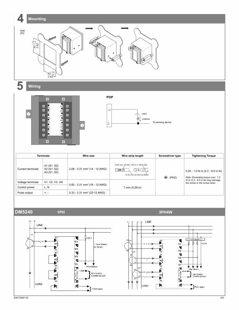
Mounting
Wiring
4
5
To sensing device
Terminals Wire size Wire strip length Screwdriver type Tightening Torque
Current terminalsA1 (S1, S2)A2 (S1, S2)A3 (S1, S2)
2.08 - 3.31 mm2 (14 - 12 AWG)
6.35 mm [0.250 in] MAX
3.68 mm ±0.08 [.145 in ±.003] DIA
(PH2)
0.25 - 1.0 N·m (2.2 - 9.0 in·lb)
Note: Exceeding torque over 1.0 N·m (2.2 - 9.0 in·lb) may damage the screw or the screw head.Voltage terminals V1, V2, V3, VN
0.82 - 3.31 mm2 (18 - 12 AWG)7 mm (0.28 in)Control power L, N
Pulse output +, - 0.33 - 3.31 mm2 (22-12 AWG)
V1
V2
S1
V3
VNS 2
A2
A1
A3
S 2
3
4
6
5
S 2
1
2
N
L
14
111
7
S1
9
10
8
S1
13
12
POP
mm(in)
+
≤40V
≤100mA
-
(7)
(14)
923.62
+ 0.8- 0.0
92 3.62
8.0+ - 0.0
DM5240 1PH 3PH4W

EAV72497-03 3/4
Wiring
DM5230 3PH3W
5
VT
Fuse
* Other meters (in series)
Control power
250 mA fuses
L and N are non-polarized. If using an AC power supply with neutral, connect neutral to the meter’s N terminal.Always use a fuse on L. Fuse N when connecting an ungrounded neutral to the control power. If using a control power transformer, fuse both primary and secondary sides of the transformer.The fuses / circuit breakers must be rated for the installation voltage and sized for the available fault current.
Tamper-resistant cover
To install the tamper-resistant cover:
1. Place the tamper-resistant cover over the terminal block.
2. Tighten the screws at the sealing points to seal the cover.
Note: The tamper-resistant cover is an optional accessory that you can order separately.
6D
NL
80-130 V AC (110 VLN nominal) OR
170-300 V AC (240 VLN nominal)
1
Tamper-resistant cover 7
Description 8Multiplying Factor (MF)The meter is calibrated for particular CT, PT ratio as mentioned on the terminal block. When the meter is used with CT, PT of the same ratio, MF is either 0.01 or 0.1 or 1.0 or 10.0 or 100.0. A decimal point has been placed on the 9 digit (6 moving and 3 dummy digits) depending on the MF. While noting the energy readings, the 9 digit energy readings need to be taken including the decimal point.
Example1 - PT : --/0.415kV, CT: --/5A for this meterMF = 0.01. Hence the decimal point placement as shown (After 4th digit).The above display shows 1234.56000kWh
Example2 - PT : 11kV/110V, CT: 250/5A for this meterMF = 100.0. Hence the decimal point placement as shown (After 8th digit).The above display shows 12345600.0kWh
POWER, INTEG, and REV LEDs POWER LED/ON LED: Indicates presence of Auxiliary Power which is essential for the meter operation.
REV LED: For cross checking connections, low current (<5 % load of CTR), and low power factor (PF) (<0.5 Lag or >0.8 Lead).
INTEG LED: Indicates that integration of Energy is in progress. The LED Blink Rate is either 10 or 8 times that of the Counter update. Hence its resolution is 10 or 8 times that of the Counter and can be conveniently used for meter calibration. Meter constant to be calculat-ed as shown below:
No. of INTG LED blinks per one count update Multiplication Factor
Note: PT ratio and CT ratio are mentioned on the terminal block.
Overflow HoursAs the Counter accumulates kWh, it will eventually reach 999999 and then overflow to 000000. The duration it takes to overflow is approxi-mately equal to (999999 x MF) / average kW.
x PT ratio x CT ratio

V1
V2
S1
V3
VNS2
A2
A1
A3
S2
3
4
6
5
S2
1
2
N
L
14
11
7
S1
9
10
8
S1
13
12
24V DCPulse Digital
Input
Control DCS or PLC
P LC
Pulse output from DM 52 can be integrated into a process through aPLC/DCS for online control ofEnergy content in a process.If the DCS/PLC has a self excited12V or 24V Digital Input, external24V DC Supply is not needed.The kWh pulses may also be used toderive average kW information atthe PLC
V1
V2
S1
V3
VNS2
A2
A1
A3
S2
3
4
6
5
S2
1
2
N
L
14
11
7
S1
9
10
8
S1
13
12
V1
V2
S1
V3
VNS2
A2
A1
A3
S2
3
4
6
5
S2
1
2
N
L
14
11
7
S1
9
10
8
S1
13
12
Several DM 52s can be networkedinto a cost effective centralisedsystem to centrally monitor energydata and generate a variety ofreports covering load-wise, shiftwise,day-wise or batch-wiseanalysis of energy consumption.
V1
V2
S1
V3
VNS2
A2
A1
A3
S2
3
4
6
5
S2
1
2
N
L
14
11
7
S1
9
10
8
S1
13
12
V1
V2
S1
V3
VNS2
A2
A1
A3
S2
3
4
6
5
S2
1
2
N
L
14
11
7
S1
9
10
8
S1
13
12
V1
V2
S1
V3
VNS2
A2
A1
A3
S2
3
4
6
5
S2
1
2
N
L
14
11
7
S1
9
10
8
S1
13
12
Specifications 9
Safety instructionsRead these instructions carefully and look at the equipment to become familiar with the device before trying to install, operate, service or maintain it. The following special messages may appear throughout this bulletin or on the equipment to warn of potential hazards or to call attention to information that clarifies or simplifies a procedure.
The addition of either symbol to a “Danger” or “Warning” safety label indicates that an electrical hazard exists which will result in personal injury if the instructions are not followed.
This is the safety alert symbol. It is used to alert you to potential personal injury hazards. Obey all safety messages that follow this symbol to avoid possible injury or death.
DANGERDANGER indicates an imminently hazardous situation which, if not avoided, will result in death or serious injury.
Electrical equipment should be installed, operated, serviced and maintained only by qualified personnel. No responsibility is assumed by Schneider Electric for any consequences arising out of the use of this material. A qualified person is one who has skills and knowledge related to the construction, installation, and operation of electrical equipment and has received safety training to recognize and avoid the hazards involved.
Conzerv and Schneider Electric are trademarks or registered trademarks of Schneider Electric in France, the USA and other countries.• This product must be installed, connected and
used in compliance with prevailing standards and/or installation regulations.
• If this product is used in a manner not specified by the manufacturer, the protection provided by the product may be impaired.
• The safety of any system incorporating this product is the responsibility of the assembler/installer of the system.
As standards, specifications and designs change from time to time, always ask for confirmation of the information given in this publication.
Accuracy• Class 1.0; as per IEC 62052-11 & IEC 62053-21 • Class 0.5; ± (0.25% of reading + 0.25% of full scale)Control power• AC: Nominal 110V (Range 80 to 130 V AC) or
Nominal 240 V (Range 170 to 300 V AC)• AC burden: 3 VA max. on Auxiliary Supply• Frequency: 45 to 65 Hz• Installation category IIIPulse output• Voltage Rating: 5 to 40 V DC• Current Rating: 100 mA max• Pulse Width: 500 ms ± 10%
Voltage inputs• Measured voltage:
◦ 110 V AC L-L (80-130 V AC) ◦ 240 V AC L-N (170-300 V AC) ◦ 415 V AC L-L (330-470 V AC)
• Frequency: 50/60 Hz• Permanent overload: 600 V AC L-L• Measurement category IIICurrent inputs• Nominal 1 A (Range: 0.25 to 6.0 A) Or
Nominal 5 A (Range: 0.05 to 1.2 A)• Withstand: 2 A continuous (1A nominal)• Withstand: 12 A continuous (5A nominal)• Burden: < 0.2 VA per phase (Volts/Amps Input)
Environment• Temperature:
◦ Operating: 0 to 50 °C ◦ Storage: -10 to 60 °C ◦ Humidity rating: 5% to 95% RH non-condensing
• Pollution degree: 2• IP30 meter body (except terminals), IP51 front display
(IEC 60529) Display• 6 digit impulse counter• Max counts 999999• Tamper-resistant, non-resettable• Retains the last recorded reading even under power failure
conditions.
© 2017 Schneider Electric. All rights reserved.03/2017
Schneider Electric India Pvt Ltd. 12A, Attibele Industrial Area, Neralur (PO), Bangalore - 562107 India email:[email protected] Toll-free Helpline number: 1800 425 4272, 1800 103 0011 www.schneider-electric.co.in
The Preset table Counter isprogrammed with the amount ofEnergy to be dispensed. When itcounts down to zero, it deenergisesthe load.
Remote Totalizer can be configured to record Data shift- wise, day -wiseetc., while DM 52 records total consumption.
Energy Totalizing Energy Dispensing
Optically Isolated, Solid-state NO Contact gives digital pulse output to drive Remote Counter, PLC, DCS Station etc. foroff line monitoring of Energy Data, on line control for Energy/Power/Process optimisation, correlating Energy Input to productoutput etc. Applications of pulse output feature are as shown below.
Process Integration Energy Management System
Remote Totalizer
Feeder 1
Feeder 2 Pulse
Pulse
Feeder 1
Feeder 2
Feeder N
DataLogger
Pulse
Pulse
Pulse
Feeder 1
Presettable counter
Control Output to Contactor12V-24V DC
Pulse output feature
EAV72497-03