daq 653x user manual - national...
TRANSCRIPT

DAQ653X User ManualHigh-Speed Digital I/O Devices for PCI, PXI , CompactPCI, AT, EISA, and PCMCIA Bus Systems
653X User Manual
™
January 2001 EditionPart Number 321464C-01

Support
Worldwide Technical Support and Product Information
ni.com
National Instruments Corporate Headquarters
11500 North Mopac Expressway Austin, Texas 78759-3504 USA Tel: 512 794 0100
Worldwide Offices
Australia 03 9879 5166, Austria 0662 45 79 90 0, Belgium 02 757 00 20, Brazil 011 284 5011, Canada (Calgary) 403 274 9391, Canada (Ottawa) 613 233 5949, Canada (Québec) 514 694 8521, China (Shanghai) 021 6555 7838, China (ShenZhen) 0755 3904939, Denmark 45 76 26 00, Finland 09 725 725 11, France 01 48 14 24 24, Germany 089 741 31 30, Greece 30 1 42 96 427, Hong Kong 2645 3186, India 91805275406, Israel 03 6120092, Italy 02 413091, Japan 03 5472 2970, Korea 02 596 7456, Mexico 5 280 7625, Netherlands 0348 433466, New Zealand 09 914 0488, Norway 32 27 73 00, Poland 0 22 528 94 06, Portugal 351 1 726 9011, Singapore 2265886, Spain 91 640 0085, Sweden 08 587 895 00, Switzerland 056 200 51 51, Taiwan 02 2528 7227, United Kingdom 01635 523545
For further support information, see the Technical Support Resources appendix. To comment on the documentation, send e-mail to [email protected]
© Copyright 1997, 2001 National Instruments Corporation. All rights reserved.

Important Information
WarrantyThe AT-DIO-32HS, DAQCard-6533 for PCMCIA, PCI-6534, PCI-DIO-32HS, PXI-6533, and PXI-6534 devices are warranted against defects in materials and workmanship for a period of one year from the date of shipment, as evidenced by receipts or other documentation. National Instruments will, at its option, repair or replace equipment that proves to be defective during the warranty period. This warranty includes parts and labor.
The media on which you receive National Instruments software are warranted not to fail to execute programming instructions, due to defects in materials and workmanship, for a period of 90 days from date of shipment, as evidenced by receipts or other documentation. National Instruments will, at its option, repair or replace software media that do not execute programming instructions if National Instruments receives notice of such defects during the warranty period. National Instruments does not warrant that the operation of the software shall be uninterrupted or error free.
A Return Material Authorization (RMA) number must be obtained from the factory and clearly marked on the outside of the package before any equipment will be accepted for warranty work. National Instruments will pay the shipping costs of returning to the owner parts which are covered by warranty.
National Instruments believes that the information in this document is accurate. The document has been carefully reviewed for technical accuracy. In the event that technical or typographical errors exist, National Instruments reserves the right to make changes to subsequent editions of this document without prior notice to holders of this edition. The reader should consult National Instruments if errors are suspected. In no event shall National Instruments be liable for any damages arising out of or related to this document or the information contained in it.
EXCEPT AS SPECIFIED HEREIN, NATIONAL INSTRUMENTS MAKES NO WARRANTIES, EXPRESS OR IMPLIED, AND SPECIFICALLY DISCLAIMS ANY WARRANTY OF MERCHANTABILITY OR FITNESS FOR A PARTICULAR PURPOSE. CUSTOMER’S RIGHT TO RECOVER DAMAGES CAUSED BY FAULT OR NEGLIGENCE ON THE PART OF NATIONAL INSTRUMENTS SHALL BE LIMITED TO THE AMOUNT THERETOFORE PAID BY THE CUSTOMER. NATIONAL INSTRUMENTS WILL NOT BE LIABLE FOR DAMAGES RESULTING FROM LOSS OF DATA, PROFITS, USE OF PRODUCTS, OR INCIDENTAL OR CONSEQUENTIAL DAMAGES, EVEN IF ADVISED OF THE POSSIBILITY THEREOF. This limitation of the liability of National Instruments will apply regardless of the form of action, whether in contract or tort, including negligence. Any action against National Instruments must be brought within one year after the cause of action accrues. National Instruments shall not be liable for any delay in performance due to causes beyond its reasonable control. The warranty provided herein does not cover damages, defects, malfunctions, or service failures caused by owner’s failure to follow the National Instruments installation, operation, or maintenance instructions; owner’s modification of the product; owner’s abuse, misuse, or negligent acts; and power failure or surges, fire, flood, accident, actions of third parties, or other events outside reasonable control.
CopyrightUnder the copyright laws, this publication may not be reproduced or transmitted in any form, electronic or mechanical, including photocopying, recording, storing in an information retrieval system, or translating, in whole or in part, without the prior written consent of National Instruments Corporation.
TrademarksComponentWorks™, CVI™, DAQCard™, IMAQ™, IVI™, LabVIEW™, Measurement Studio™, MITE™, National Instruments™, ni.com™, NI-DAQ™, PXI™, RTSI™, SCXI™, and VirtualBench™ are trademarks of National Instruments Corporation.
Product and company names mentioned herein are trademarks or trade names of their respective companies.
WARNING REGARDING USE OF NATIONAL INSTRUMENTS PRODUCTS(1) NATIONAL INSTRUMENTS PRODUCTS ARE NOT DESIGNED WITH COMPONENTS AND TESTING FOR A LEVEL OF RELIABILITY SUITABLE FOR USE IN OR IN CONNECTION WITH SURGICAL IMPLANTS OR AS CRITICAL COMPONENTS IN ANY LIFE SUPPORT SYSTEMS WHOSE FAILURE TO PERFORM CAN REASONABLY BE EXPECTED TO CAUSE SIGNIFICANT INJURY TO A HUMAN.
(2) IN ANY APPLICATION, INCLUDING THE ABOVE, RELIABILITY OF OPERATION OF THE SOFTWARE PRODUCTS CAN BE IMPAIRED BY ADVERSE FACTORS, INCLUDING BUT NOT LIMITED TO FLUCTUATIONS IN ELECTRICAL POWER SUPPLY, COMPUTER HARDWARE MALFUNCTIONS, COMPUTER OPERATING SYSTEM SOFTWARE FITNESS, FITNESS OF COMPILERS AND DEVELOPMENT SOFTWARE USED TO DEVELOP AN APPLICATION, INSTALLATION ERRORS, SOFTWARE AND HARDWARE COMPATIBILITY PROBLEMS, MALFUNCTIONS OR FAILURES OF ELECTRONIC MONITORING OR CONTROL DEVICES, TRANSIENT FAILURES OF ELECTRONIC SYSTEMS (HARDWARE AND/OR SOFTWARE), UNANTICIPATED USES OR MISUSES, OR ERRORS ON THE PART OF THE USER OR APPLICATIONS DESIGNER (ADVERSE FACTORS SUCH AS THESE ARE HEREAFTER COLLECTIVELY TERMED “SYSTEM FAILURES”). ANY APPLICATION WHERE A SYSTEM FAILURE WOULD CREATE A RISK OF HARM TO PROPERTY OR PERSONS (INCLUDING THE RISK OF BODILY INJURY AND DEATH) SHOULD NOT BE RELIANT SOLELY UPON ONE FORM OF ELECTRONIC SYSTEM DUE TO THE RISK OF SYSTEM FAILURE. TO AVOID DAMAGE, INJURY, OR DEATH, THE USER OR APPLICATION DESIGNER MUST TAKE REASONABLY PRUDENT STEPS TO PROTECT AGAINST SYSTEM FAILURES, INCLUDING BUT NOT LIMITED TO BACK-UP OR SHUT DOWN MECHANISMS. BECAUSE EACH END-USER SYSTEM IS CUSTOMIZED AND DIFFERS FROM NATIONAL INSTRUMENTS' TESTING PLATFORMS AND BECAUSE A USER OR APPLICATION DESIGNER MAY USE NATIONAL INSTRUMENTS PRODUCTS IN COMBINATION WITH OTHER PRODUCTS IN A MANNER NOT EVALUATED OR CONTEMPLATED BY NATIONAL INSTRUMENTS, THE USER OR APPLICATION DESIGNER IS ULTIMATELY RESPONSIBLE FOR VERIFYING AND VALIDATING THE SUITABILITY OF NATIONAL INSTRUMENTS PRODUCTS WHENEVER NATIONAL INSTRUMENTS PRODUCTS ARE INCORPORATED IN A SYSTEM OR APPLICATION, INCLUDING, WITHOUT LIMITATION, THE APPROPRIATE DESIGN, PROCESS AND SAFETY LEVEL OF SUCH SYSTEM OR APPLICATION.

Compliance
FCC/Canada Radio Frequency Interference Compliance*
Determining FCC ClassThe Federal Communications Commission (FCC) has rules to protect wireless communications from interference. The FCC places digital electronics into two classes. These classes are known as Class A (for use in industrial-commercial locations only) or Class B (for use in residential or commercial locations). Depending on where it is operated, this product could be subject to restrictions in the FCC rules. (In Canada, the Department of Communications (DOC), of Industry Canada, regulates wireless interference in much the same way.)
Digital electronics emit weak signals during normal operation that can affect radio, television, or other wireless products. By examining the product you purchased, you can determine the FCC Class and therefore which of the two FCC/DOC Warnings apply in the following sections. (Some products may not be labeled at all for FCC; if so, the reader should then assume these are Class A devices.)
FCC Class A products only display a simple warning statement of one paragraph in length regarding interference and undesired operation. Most of our products are FCC Class A. The FCC rules have restrictions regarding the locations where FCC Class A products can be operated.
FCC Class B products display either a FCC ID code, starting with the letters EXN, or the FCC Class B compliance mark that appears as shown here on the right.
Consult the FCC web site http://www.fcc.gov for more information.
FCC/DOC WarningsThis equipment generates and uses radio frequency energy and, if not installed and used in strict accordance with the instructions in this manual and the CE Mark Declaration of Conformity**, may cause interference to radio and television reception. Classification requirements are the same for the Federal Communications Commission (FCC) and the Canadian Department of Communications (DOC).
Changes or modifications not expressly approved by National Instruments could void the user’s authority to operate the equipment under the FCC Rules.
Class AFederal Communications Commission
This equipment has been tested and found to comply with the limits for a Class A digital device, pursuant to part 15 of the FCC Rules. These limits are designed to provide reasonable protection against harmful interference when the equipment is operated in a commercial environment. This equipment generates, uses, and can radiate radio frequency energy and, if not installed and used in accordance with the instruction manual, may cause harmful interference to radio communications. Operation of this equipment in a residential area is likely to cause harmful interference in which case the user will be required to correct the interference at his own expense.
Canadian Department of CommunicationsThis Class A digital apparatus meets all requirements of the Canadian Interference-Causing Equipment Regulations.
Cet appareil numérique de la classe A respecte toutes les exigences du Règlement sur le matériel brouilleur du Canada.
Class BFederal Communications Commission
This equipment has been tested and found to comply with the limits for a Class B digital device, pursuant to part 15 of the FCC Rules. These limits are designed to provide reasonable protection against harmful interference in a residential installation. This equipment generates, uses and can radiate radio frequency energy and, if not installed and used in accordance with the instructions, may cause harmful interference to radio communications. However, there is no guarantee that interference will not occur in a particular installation. If this equipment does cause harmful interference to radio or television reception, which can be determined by turning the equipment off and on, the user is encouraged to try to correct the interference by one or more of the following measures:• Reorient or relocate the receiving antenna.• Increase the separation between the equipment and receiver.

• Connect the equipment into an outlet on a circuit different from that to which the receiver is connected.• Consult the dealer or an experienced radio/TV technician for help.
Canadian Department of CommunicationsThis Class B digital apparatus meets all requirements of the Canadian Interference-Causing Equipment Regulations.
Cet appareil numérique de la classe B respecte toutes les exigences du Règlement sur le matériel brouilleur du Canada.
European Union - Compliance to EEC DirectivesReaders in the EU/EEC/EEA must refer to the Manufacturer's Declaration of Conformity (DoC) for information** pertaining to the CE Mark compliance scheme. The Manufacturer includes a DoC for most every hardware product except for those bought for OEMs, if also available from an original manufacturer that also markets in the EU, or where compliance is not required as for electrically benign apparatus or cables.
* Certain exemptions may apply in the USA, see FCC Rules §15.103 Exempted devices, and §15.105(c). Also available in sections of CFR 47.
** The CE Mark Declaration of Conformity will contain important supplementary information and instructions for the user or installer.

Conventions
The following conventions appear in this manual:
<> Angle brackets that contain numbers separated by an ellipsis represent a range of values associated with a bit or signal name—for example, DBIO<3..0>.
» The » symbol leads you through nested menu items and dialog box options to a final action. The sequence File»Page Setup»Options directs you to pull down the File menu, select the Page Setup item, and select Options from the last dialog box.
This icon denotes a tip, which alerts you to advisory information.
This icon denotes a note, which alerts you to important information.
This icon denotes a caution, which advises you of precautions to take to avoid injury, data loss, or a system crash.
This icon denotes a warning, which advises you of precautions to take to avoid being electrically shocked.
bold Bold text denotes items that you must select or click on in the software, such as menu items and dialog box options. Bold text also denotes parameter names.
italic Italic text denotes variables, emphasis, a cross reference, or an introduction to a key concept. This font also denotes text that is a placeholder for a word or value that you must supply.
monospace Text in this font denotes text or characters that you should enter from the keyboard, sections of code, programming examples, and syntax examples. This font is also used for the proper names of disk drives, paths, directories, programs, subprograms, subroutines, device names, functions, operations, variables, filenames and extensions, and code excerpts.

© National Instruments Corporation vii 653X User Manual
Contents
Chapter 1Getting Started with Your 653X
653X Device Overview..................................................................................................1-1Control Lines ...................................................................................................1-1
What You Need to Get Started ......................................................................................1-2Choosing Your Programming Software ........................................................................1-3
National Instruments Application Software ....................................................1-3NI-DAQ Driver Software ................................................................................1-4
Installing Your Software................................................................................................1-5Unpacking Your 653X Device .......................................................................................1-5Installing Your 653X Device .........................................................................................1-6
Installing the PCI-DIO-32HS, PCI-6534, or PCI-7030/6533 .........................1-6Installing the PXI-6533, PXI-6534, or PXI-7030/6533 ..................................1-7Installing the AT-DIO-32HS...........................................................................1-7Installing the DAQCard-6533 for PCMCIA ...................................................1-8
Configuring the 653X.....................................................................................................1-8In Windows .....................................................................................................1-8In Mac OS........................................................................................................1-9
Chapter 2Using Your 653X
Choosing the Correct Mode for Your Application ........................................................2-1Controlling and Monitoring Static Digital Lines—Unstrobed I/O................................2-2
Configuring Digital Lines................................................................................2-2Standard Output ................................................................................2-2Wired-OR Output..............................................................................2-2
Using Control Lines as Extra Unstrobed Data Lines ......................................2-3Connecting Signals..........................................................................................2-4Creating a Program..........................................................................................2-4
Programming the Control/Timing Lines as Extra Unstrobed Data Lines ......................................................................................2-5
Transferring Data Between Two Devices—Handshaking I/O ......................................2-6Deciding the Width of Data to Transfer ..........................................................2-6Deciding Data Transfer Direction ...................................................................2-6Deciding Which Handshaking Protocol to Use...............................................2-7Using the Burst Protocol .................................................................................2-7
Deciding the PCLK Signal Direction................................................2-7Selecting ACK/REQ Signal Polarity...............................................................2-8

Contents
653X User Manual viii ni.com
Choosing Whether or Not to Use a Programmable Delay .............................. 2-8Choosing Continuous or Finite Data Transfer ................................................ 2-9
Finite Transfers................................................................................. 2-9Continuous Input .............................................................................. 2-9Continuous Output............................................................................ 2-9Choosing DMA or Interrupt Transfers ............................................. 2-10
Connecting Signals ......................................................................................... 2-10Choosing the Startup Sequence....................................................................... 2-11
Using an Initialization Order ............................................................ 2-11Controlling Line Polarities ............................................................... 2-12
Creating a Program ......................................................................................... 2-12Generating and Receiving Digital Patterns and Waveforms—Pattern I/O ................... 2-17
Deciding the Width of Data to Transfer.......................................................... 2-17Deciding Transfer Direction ........................................................................... 2-18Choosing an Internal or External REQ Source ............................................... 2-18Deciding the REQ Polarity ............................................................................. 2-18Deciding the Transfer Rate ............................................................................. 2-18Deciding How to Start and Stop Data Transfer—Triggering ......................... 2-19
Start and Stop Trigger....................................................................... 2-20Choosing Continuous or Finite Data Transfer ................................................ 2-21
Finite Transfers................................................................................. 2-21Continuous Input .............................................................................. 2-21Continuous Output............................................................................ 2-22Choosing DMA or Interrupt Transfers ............................................. 2-22
Monitoring Data Transfer ............................................................................... 2-23Connecting Signals ......................................................................................... 2-23Creating a Program ......................................................................................... 2-24
Monitoring Line State—Change Detection................................................................... 2-26Deciding the Width of Data to Acquire .......................................................... 2-26Deciding Which Lines You Want to Monitor................................................. 2-27Deciding How to Start and Stop Data Transfer—Triggering ......................... 2-27
Start and Stop Trigger....................................................................... 2-28Choosing Continuous or Finite Data Transfer ................................................ 2-30
Finite Transfers................................................................................. 2-30Continuous Input .............................................................................. 2-30Choosing DMA or Interrupt Transfers ............................................. 2-31
Connecting Signals ......................................................................................... 2-31Creating a Program ......................................................................................... 2-31
Chapter 3Timing Diagrams
Pattern I/O Timing Diagrams ........................................................................................ 3-1Internal REQ Signal Source ............................................................................ 3-1

Contents
© National Instruments Corporation ix 653X User Manual
External REQ Signal Source ...........................................................................3-2Handshaking I/O Timing Diagrams...............................................................................3-4
Comparing the Different Handshaking Protocols ...........................................3-4Using the Burst Protocol .................................................................................3-5Using Asynchronous Protocols .......................................................................3-12Using the 8255-Emulation Protocol ................................................................3-12Using the Level-ACK Protocol .......................................................................3-18Using Protocols Based on Signal Edges..........................................................3-24Using the Trailing-Edge Protocol....................................................................3-25
Appendix ASpecifications
Appendix BUsing PXI with CompactPCI
Appendix CConnecting Signals with Accessories
Appendix DHardware Considerations
Appendix EOptimizing Your Transfer Rates
Appendix FTechnical Support Resources
Glossary
Index

© National Instruments Corporation 1-1 653X User Manual
1Getting Started with Your 653X
The 653X User Manual describes installing, configuring, setting up, and programming applications for your AT-DIO-32HS, DAQCard-6533 for PCMCIA, PCI-6534, PCI-DIO-32HS, PXI-6533, PXI-6534, or PCI/PXI-7030/6533 device.
653X Device OverviewWith 653X devices, you can use your computer or chassis as a digital I/O tester, logic analyzer, or system controller for laboratory testing, production testing, and industrial process monitoring and control.
Each 653X device provides 32 digital data lines that are individually configurable as input or output, grouped into four 8-bit ports. Each line can sink or source 24 mA of current.
The 6534 devices contain onboard memory, enabling you to transfer data to/from this memory at a guaranteed rate. This memory feature removes the dependency on the host computer bus for applications that require guaranteed transfer rates.
The PCI/PXI-7030/6533 is an RT Series DAQ device that contains a processor board (7030), a daughter device, and an independent processor that runs LabVIEW Real-Time applications. The 6533 daughter device contains all the features and functions of the PCI/PXI-6533 devices described in this manual. For more information about your PCI/PXI-7030/6533 device, see the RT Series DAQ Device User Manual.
Detailed 653X device specifications are in Appendix A, Specifications.
Control LinesIn addition to controlling and monitoring relay-type applications, your device also provides two timing/handshaking controllers for high-speed data transfer. They are named Group 1 and Group 2. Each group has four control lines which can be used to time the input/output of data with hardware precision.

Chapter 1 Getting Started with Your 653X
653X User Manual 1-2 ni.com
Use Group 1 and 2 to:
• Generate or receive digital patterns and waveforms timed by a TTL clock
• Transfer data between two devices using one of six configurable handshaking protocols
• Acquire a digital pattern every time the state of a data line changes
What You Need to Get StartedTo begin using your 653X device, you need the following:
One or more of the following devices:
– AT-DIO-32HS
– DAQCard-6533 for PCMCIA
– PCI-6534
– PCI-DIO-32HS
– PXI-6533
– PXI-6534
– PCI or PXI-7030/6533 (RT Series DAQ device)
653X User Manual
NI-DAQ (for PC compatibles or Mac OS)
Software environments supported by NI-DAQ (optional):
– LabVIEW (for Windows or Mac OS)
– LabVIEW Real-Time (LabVIEW RT)
– Measurement Studio (for Windows only)
– Virtual Bench
– Other supported compilers
The appropriate signal connector
The appropriate shielded or ribbon cable. Refer to Appendix C, Connecting Signals with Accessories, for specific information about cables that are compatible with your device.
Your computer or PXI/CompactPCI chassis and controller

Chapter 1 Getting Started with Your 653X
© National Instruments Corporation 1-3 653X User Manual
Choosing Your Programming SoftwareWhen programming your National Instruments measurement hardware, you can use either National Instruments application software or another application development environment (ADE).
National Instruments Application Software LabVIEW and LabVIEW RT feature interactive graphics, a state-of-the-art user interface, and a powerful graphical programming language. The LabVIEW Data Acquisition Virtual Instrument (VI) Library, a series of virtual instruments for using LabVIEW with National Instruments DAQ hardware, is included with LabVIEW. The LabVIEW Data Acquisition VI Library is functionally equivalent to the NI-DAQ API.
As with LabVIEW, you develop your LabVIEW RT applications with graphical programming, then download the program to run on an independent hardware target with a real-time operating system. LabVIEW RT allows you to use the 6533 digital DAQ devices in two different configurations: PCI/PXI-7030/6533 devices, and PXI-6533 devices in PXI systems being controlled in real time by LabVIEW RT.
Measurement Studio, which includes LabWindows/CVI, tools for Visual C++, and tools for Visual Basic, is a development suite that allows you to use ANSI C, Visual C++, and Visual Basic to design your test and measurement software. For C developers, Measurement Studio includes LabWindows/CVI, a fully integrated ANSI C application development environment that features interactive graphics and the LabWindows/CVI Data Acquisition and Easy I/O libraries. For Visual Basic developers, Measurement Studio features a set of ActiveX controls for using National Instruments DAQ hardware. These ActiveX controls provide a high-level programming interface for building virtual instruments. For Visual C++ developers, Measurement Studio offers a set of Visual C++ classes and tools to integrate those classes into Visual C++ applications. The libraries, ActiveX controls, and classes are available with Measurement Studio and the NI-DAQ software.
VirtualBench features virtual instruments that combine DAQ products, software, and your computer to create a stand-alone instrument with the added benefits of the processing, display, and storage capabilities of your computer. VirtualBench instruments load and save waveform data to disk in the same forms that can be used in popular spreadsheet programs and word processors.

Chapter 1 Getting Started with Your 653X
653X User Manual 1-4 ni.com
Using LabVIEW, Measurement Studio, or VirtualBench software greatly reduces the development time for your data acquisition and control application.
NI-DAQ Driver SoftwareThe NI-DAQ driver software shipped with your 653X device has an extensive library of functions that you can call from your application programming environment. These functions allow you to use all the features of your 653X device.
NI-DAQ addresses many of the complex issues between the computer and the DAQ hardware, such as programming interrupts. NI-DAQ maintains a consistent software interface among its different versions so that you can change platforms with minimal modifications to your code. Whether you are using LabVIEW, Measurement Studio, or another programming language, your application uses the NI-DAQ driver software, as illustrated in Figure 1-1.
Figure 1-1. The Relationship Between the Programming Environment, NI-DAQ, and Your Hardware
LabVIEW, LabVIEW RT,Measurement Studio,
or Virtual Bench
Conventional Programming Environment
NI-DAQDriver Software
DAQ orSCXI Hardware
Personal Computer or Workstation

Chapter 1 Getting Started with Your 653X
© National Instruments Corporation 1-5 653X User Manual
To download a free copy of the most recent version of NI-DAQ, click Download Software at ni.com. Find NI-DAQ compatibility for your device using the following table:
Installing Your SoftwareInstall application development software, such as LabVIEW or Measurement Studio, according to instructions on the CD and the release notes. If NI-DAQ was not installed with your ADE, then install NI-DAQ according to the instructions on the CD and the DAQ Quick Start Guide included with your device.
Note It is important to install the NI-DAQ driver software before installing your device(s) to ensure the device(s) are properly detected.
Unpacking Your 653X DeviceYour 653X device is shipped in an antistatic package to prevent electrostatic damage to the device. To avoid such damage in handling the device, take the following precautions:
• Ground yourself via a grounding strap or by holding a grounded object.
• Touch the antistatic package to a metal part of your computer chassis before removing the device from the package.
Caution Never touch the exposed pins of connectors to prevent electrostatic discharge from damaging the device.
Device Supported
NI-DAQ Version
Windows Mac
PCI-DIO-32HS Version 5.0 or later Version 6.1.0 or later
AT-DIO-32HS Version 5.0 or later N/A
PXI-6533 Version 5.1 or later Version 6.1.3 or later
DAQCard-6533 for PCMCIA Version 5.1 or later Version 6.1.0 or later
PXI-6534 Version 6.9 or later N/A
PCI-6534 Version 6.9 or later N/A
PCI or PXI-7030/6533 Version 6.5.2 or later N/A

Chapter 1 Getting Started with Your 653X
653X User Manual 1-6 ni.com
Remove the device from the package and inspect the device for loose components or any sign of damage. Notify National Instruments if the device appears damaged in any way. Do not install a damaged device into your computer.
Store your 653X device in the antistatic envelope when not in use.
Installing Your 653X DeviceThe following are general installation instructions. Consult your computer or chassis user manual or technical reference manual for specific instructions and warnings about installing new devices.
Note It is important to install the NI-DAQ driver software before installing your device(s) to ensure the device(s) are properly detected.
Installing the PCI-DIO-32HS, PCI-6534, or PCI-7030/6533You can install a PCI-DIO-32HS, PCI-6534, or PCI-7030/6533 device in any available 5 V PCI expansion slot in your computer.
1. Turn off and unplug your computer.
2. Remove the cover.
3. Remove the expansion slot cover on the back panel of the computer.
4. Touch a metal part of your computer chassis to discharge any static electricity that might be on your clothes or body.
5. Insert the 653X device into a 5 V PCI slot. It can be a tight fit, but do not force the device into place.
6. Screw the mounting bracket of the 653X device to the back panel rail of the computer.
7. Visually verify the installation. Make sure the device is not touching other boards or components and is inserted fully in the slot.
8. Replace the cover of your computer.
9. Plug in and turn on your computer.
Now that your 653X device is installed, it is ready to be configured.

Chapter 1 Getting Started with Your 653X
© National Instruments Corporation 1-7 653X User Manual
Installing the PXI-6533, PXI-6534, or PXI-7030/6533You can install a PXI-653X or PXI-7030/6533 device any available 5 V peripheral slot in your PXI or CompactPCI chassis.
Note Your PXI device has connections to several reserved lines on the CompactPCI J2 connector. Before installing a PXI device in a CompactPCI system that uses J2 connector lines for purposes other than PXI, see Appendix C, Connecting Signals with Accessories.
1. Turn off and unplug your PXI or CompactPCI chassis.
2. Choose an unused PXI or CompactPCI 5 V peripheral slot.
Tip For maximum performance of your CompactPCI, install the PXI-653X in a slot that supports bus arbitration or bus-master cards. The PXI-653X contains onboard bus-master DMA logic that can operate only in such a slot. If you install in a slot that does not support bus masters, you must disable the PXI-653X onboard DMA controller using your software. PXI-compliant chassis have bus arbitration for all slots.
3. Remove the filler panel for the peripheral slot you have chosen.
4. Touch a metal part on your chassis to discharge any static electricity that might be on your clothes or body.
5. Insert the PXI-653X in a 5 V slot. Use the injector/ejector handle to fully inject the device into place.
6. Screw the front panel of the PXI-653X to the front panel mounting rails of the PXI or CompactPCI chassis.
7. Visually verify the installation. Make sure the device is not touching other boards or components and is fully in the slot.
8. Plug in and turn on the PXI or CompactPCI chassis.
Now that your 653X device is installed, it is ready to be configured.
Installing the AT-DIO-32HSYou can install an AT-DIO-32HS in any available AT (16-bit ISA) or EISA expansion slot in your computer.
1. Turn off and unplug your computer.
2. Remove the cover.
3. Remove the expansion slot cover on the back panel of the computer.
4. Touch a metal part of your computer chassis to discharge any static electricity that might be on your clothes or body.

Chapter 1 Getting Started with Your 653X
653X User Manual 1-8 ni.com
5. Insert the AT-DIO-32HS into an AT (16-bit ISA) or EISA slot. It can be a tight fit, but do not force the device into place.
6. Screw the mounting bracket of the AT-DIO-32HS to the back panel rail of the computer.
7. Visually verify the installation. Make sure the device is not touching other boards or components and is fully inserted in the slot.
8. Replace the cover of the computer.
9. Plug in and turn on your computer.
Now that your 653X device is installed, it is ready to be configured.
Installing the DAQCard-6533 for PCMCIAYou can install your DAQCard-6533 for PCMCIA in any available CardBus-compatible Type II PCMCIA slot. Consult the computer manufacturer for information about slot compatibility.
1. Turn off your computer. If your computer and operating system support hot insertion, you may insert or remove the DAQCard-6533 at any time, whether the computer is powered on or off.
2. Remove the PCMCIA slot cover on your computer, if any.
Now that your 653X device is installed, it is ready to be configured.
Configuring the 653XYour 653X device is configured automatically in Measurement & Automation Explorer (MAX), which is installed with the NI-DAQ driver software in Windows, or in the NI-DAQ Configuration Utility, which is installed with NI-DAQ in the Mac OS. All settings are initially configured to default settings.
In WindowsIf you would like to change or view default settings, follow these instructions, also available in your DAQ Quick Start Guide:
1. Launch MAX.
2. Open Devices and Interfaces.
3. Right-click the device you want to configure and choose Properties.
4. Press the Test Resources button to test hardware resources.

Chapter 1 Getting Started with Your 653X
© National Instruments Corporation 1-9 653X User Manual
To create a virtual channel, or to learn about other capabilities of MAX, read the MAX online help by selecting Help»Help Topics and select NI-DAQ from the menu.
In Mac OSTo view and test current resource allocation:
1. Open the NI-DAQ Configuration Utility.
2. Select the device you want to configure.
3. Click the Configure button.
4. Press the Test Resources button to test hardware resources.
Warning Do not configure the 653X resources in conflict with non-National Instruments devices. For example, do not configure two devices to have the same base address.
Note The PCI/PXI-7030/6533 configuration is similar to PCI/PXI-653X configuration with a few exceptions. Refer to your PCI/PXI-7030 and LabVIEW RT User Manual for specific configuration details.
Note If you are using the AT-DIO-32HS device in a non-Plug and Play system, the device automatically configures to a switchless DAQ device so it can work in the system.
Now that you have completed configuring your device, you can begin setting up the device for use.

© National Instruments Corporation 2-1 653X User Manual
2Using Your 653X
To begin using your 653X device, navigate this chapter in the following order:
1. Choose the correct mode of operation to perform using the table below.
2. Follow the instructions for the application you want to perform.
3. Refer to pinout diagrams in Appendix C, Connecting Signals with Accessories, when you are ready to connect your devices and/or accessories.
Tip See the glossary for definitions to digital I/O terms used throughout this chapter.
Choosing the Correct Mode for Your ApplicationUse the following table to find the correct mode for your application:
Application Requirements Suggested Mode to Use
I need to perform basic digital I/O that does not need hardware timing or handshaking between the 653X and the peripheral device.
Unstrobed I/O
I want to configure the direction of each bit individually instead of groups of eight. Unstrobed I/O
I want to connect two or more output drivers/pins to the same line. Unstrobed output with wired-OR driver
I need to communicate with an external device using an exchange of signals to request and acknowledge each data transfer.
Handshaking I/O–Select appropriate protocol
I want to start and/or stop acquiring data upon a trigger and/or to transfer data at timed intervals. Pattern I/O
I want the 653X to capture input data only when certain lines change states. Change Detection
I want to monitor activity on input lines without continuously polling or transferring unnecessary data during periods of inactivity.
Change Detection

Chapter 2 Using Your 653X
653X User Manual 2-2 ni.com
Controlling and Monitoring Static Digital Lines—Unstrobed I/O
This section explains how to control and monitor static digital lines through software-timed reads and writes to and from the digital lines of your 653X device.
Configuring Digital LinesFor unstrobed I/O, the direction of each of the 32 data lines is individually configurable. You can configure each data line to one of the following:
• Input
• Standard output
• Wired-OR output
Standard OutputA standard driver drives its output pin to approximately 0 V for logic low, or +5 V for logic high. Advantages include:
• It does not require pull-up resistors.
• It is independent of the state of the DPULL line.
• It has high current drive for both its logic high and logic low states.
• It can drive high-speed transitions in both the high-to-low and low-to-high directions.
Wired-OR OutputA wired-OR output driver drives its output pin to 0 V for logic low. For logic high, the output driver assumes a high-impedance state and does not drive a voltage. This is called tri-state. To pull the pin to +5 V for logic high, a pull-up resistor is required.
To provide a pull-up resistor, connect the DPULL pin on the I/O connector to the +5 V pin. This provides 100 kΩ pull-up resistors on all data lines. For more information about CPULL and DPULL, see the Power-On State section in Appendix D, Hardware Considerations.

Chapter 2 Using Your 653X
© National Instruments Corporation 2-3 653X User Manual
Advantages of using the wired-OR driver include:
• The ability to connect two or more wired-OR outputs together without damaging the drivers.
• The ability to connect wired-OR outputs to open-collector drivers, to GND signals, or to switches connecting to GND signals, without damaging the drivers.
• The ability to use wired-OR outputs bidirectionally. If you connect wired-OR outputs together, you can read back the value of a pin to determine if any connected outputs are logic low.
Using Control Lines as Extra Unstrobed Data LinesThe 653X device has two timing controllers for high-speed data transfer (Group 1 and Group 2). Each group contains four control lines which can be used to time the input/output of data with hardware precision. You can use Groups 1 and 2 to:
• Generate or receive digital patterns and waveforms at regular intervals or timed by an external TTL signal.
• Transfer data between two devices using one of six configurable handshaking protocols.
• Acquire digital data every time the state of a data line changes.
Note If you configure either group to perform handshaking I/O or pattern I/O, the associated timing control lines for that group will not be available for unstrobed I/O.
If you are not using Group 1 and/or Group 2 as timing controllers to perform pattern I/O or handshaking I/O, you can use their control lines as extra data lines. These lines constitute Port 4. The direction and output driver type of these lines are not configurable—four lines are used as input only and four are used as standard output only. Even though there are eight actual lines, the port width for Port 4 is 4 bits. In software, these lines are collectively referred to as Port 4; when writing to Port 4, the output lines are affected, and when reading from Port 4, the input lines are read. Table 2-1 displays how Port 4 lines are organized.

Chapter 2 Using Your 653X
653X User Manual 2-4 ni.com
Connecting SignalsConnect digital input signals to the I/O connector using the pinout diagrams, Figures C-1, 653X I/O Connector 68-Pin Assignments, and C-2, 68-to-50-Pin Adapter Pin Assignments.
Creating a ProgramUsing the following flowcharts as a guide, create a program to perform unstrobed I/O. Figure 2-1 displays a flowchart for C programming using NI-DAQ, while Figure 2-2 shows a LabVIEW programming flowchart.
The boxes represent function names for the appropriate software, and the diamonds represent decision points.
Table 2-1. Port 4 Lines
Direction Line I/O Pins
Input 0 STOPTRIG 1
1 STOPTRIG 2
2 REQ 1
3 REQ 2
Output (standard) 0 PCLK 1
1 PCLK 2
2 ACK 1
3 ACK 2

Chapter 2 Using Your 653X
© National Instruments Corporation 2-5 653X User Manual
Figure 2-1. Programming Unstrobed I/O in NI-DAQs
Figure 2-2. Programming Unstrobed I/O in LabVIEW/LabVIEW RT
Programming the Control/Timing Lines as Extra Unstrobed Data LinesIf you want to use the control/timing lines as extra unstrobed data lines:
• NI-DAQ C Interface—If both sets of control/timing lines are available, call the DIG_In_Prt or DIG_Out_Prt function and set Port Number to 4. If both sets of control/timing lines are not available, use the DIG_In_Line and DIG_Out_Line functions to individually read/write to the appropriate control/timing lines.
NoYes
Only OneLine?
DIG_Line_ConfigDIG_Prt_Config
DIG_Out_prtDIG_In_prt
Read?
Done?
NoYes
DIG_Out_LineDIG_In_Line
Done?
Read?
No
No
Yes
No
Read from Digital Line VI
Single Line?Yes No
Write to Digital Port VI
Read from Digital Port VI
Write to Digital Line VI

Chapter 2 Using Your 653X
653X User Manual 2-6 ni.com
• LabVIEW—Use one of the top-level VIs: the Read From Digital Line VI to read from a digital port, and the Write to Digital Line VI to write to a digital port. The digital channel number is 4 and the port width is 4. If one of the control/timing lines is used or reserved and you are using the write or read port VIs, use the Line Mask parameter in the DIO Port Write VI to mask out the appropriate lines.
Transferring Data Between Two Devices—Handshaking I/O
If you want to communicate with an external device using an exchange of signals to request and acknowledge each data transfer, use the handshaking I/O mode.
Deciding the Width of Data to TransferYou can choose between a width of eight, 16, or 32 bits. Use the following table to find the valid combinations of ports and timing controllers you can use based on the width of data you want to transfer.
Deciding Data Transfer DirectionYou can choose to send data from the 653X device to the peripheral device (output) or from the peripheral device to the 653X device (input).
Table 2-2. Port and Timing Controller Combinations
Transfer Width
Possible Port Combinations
Timing Controllers That Can Be Used
8 bits Port 0 (DIOA<0..7>) Group 1
Port 2 (DIOC<0..7>) Group 2
16 bits Port 0, Port 1 Group 1
Port 2, Port 3 Group 2
32 bits Port 0, Port 1, Port 2, Port 3 Group 1

Chapter 2 Using Your 653X
© National Instruments Corporation 2-7 653X User Manual
Deciding Which Handshaking Protocol to UseThe 653X device supports several different handshaking protocols to communicate with your peripheral device. The protocol you select will determine the timing of the ACK and REQ signals.
From the perspective of the 653X device, the peripheral device requests the transfer of data by signaling on the REQ line. The 653X device acknowledges it is ready to transfer data by signaling on the ACK line.
Use Table 3-1, Handshaking Protocol Characteristics, to select a handshaking protocol for your application. To select a protocol compatible with your peripheral device, compare the handshaking sequence and state machine diagrams for each protocol in the later sections of Chapter 3, Timing Diagrams.
Using the Burst ProtocolThe burst protocol differs from all the other handshaking protocols in that it is the only synchronous (clocked) protocol. In addition to ACK and REQ, the 653X and peripheral device share a clock signal over the PCLK line. See Chapter 3, Timing Diagrams, for more information about the burst protocol.
If you want to acquire or generate patterns of every edge of a clock signal, see the Generating and Receiving Digital Patterns and Waveforms—Pattern I/Osection.
Note Feed external clocking signals into the PCLK pin for burst-mode handshaking and into the REQ pin when performing pattern I/O.
Deciding the PCLK Signal DirectionThe 653X device can receive an external PCLK signal to control data transfers or generate a PCLK signal using an internal 32-bit counter to output to the peripheral device. By default, the 653X device generates the PCLK signal for input operations and receives an external PCLK signal for output operations.

Chapter 2 Using Your 653X
653X User Manual 2-8 ni.com
To set the direction of the PCLK signal:
• NI-DAQ C interface—Set the ND_CLOCK_REVERSE_MODE to ND_ON in Set_DAQ_Device_Info.
• LabVIEW—Set the Clock Reverse Mode attribute to ON in the DIO Parameter VI.
Note For more information on LabVIEW VIs and NI-DAQ functions, consult the LabVIEW Help and the NI-DAQ Function Reference Help.
Selecting ACK/REQ Signal PolarityFor all handshaking protocols except 8255 emulation, you can set the polarity of the ACK and REQ signals to Active High or Active Low through software. By default, these signals are active high in NI-DAQ functions and active low in LabVIEW VIs. Refer to Table C-1, 653X I/O Connector 68-Pin Assignments, for an overview of all control/timing trigger lines.
Choosing Whether or Not to Use a Programmable DelayFor all the protocols, you have the option to set a programmable delay. This is useful when the handshaking signals of the 653X device occur faster than the peripheral device can handle.
For all protocols except burst, the delay increases the time the 653X device takes to respond to the REQ signal. For the burst protocol, the programmable delay selects the frequency of the clock signal when you are using an internally generated clock source. You can change the PCLK frequency by modifying the ACK Modify Amount parameter of the Digital Mode Config VI or the ACK Delay Time attribute of the DIG_Grp_Mode function in NI-DAQ C interface. Use the following table to find the resulting period in nanoseconds. The PCLK frequency is then selected by the driver based on this choice.
PCLK Period in ns PCLK Frequency in MHz
50 20
100 10
200 5
300 3.33
400 2.5

Chapter 2 Using Your 653X
© National Instruments Corporation 2-9 653X User Manual
The state machine diagrams in Chapter 3, Timing Diagrams, show more precisely where this delay occurs in the handshaking sequence.
Choosing Continuous or Finite Data TransferYou can transfer data indefinitely to/from computer memory or finitely by specifying the number of points you want to transfer.
Finite TransfersFor finite transfers, the 653X device transfers the specified amount of data to/from a computer memory buffer and stops the operation.
Continuous InputFor continuous input, the 653X device transfers input data to the computer memory buffer continuously. As the device is filling the buffer, call the DIG_DB_Transfer function or the DIO Read VI to retrieve the data. If at any time the device runs out of space in the buffer, it pauses the handshaking operation until your program clears up more buffer space.
You have the option to allow the device to continue acquiring data when it runs out of buffer space and overwrite data you have not yet read. You can specify this through the oldDataStop parameter in the DIG_DB_Config function and the Data Overwrite/Regenerate parameter in the Digital Buffer Control VI called by the DIO Start VI.
Continuous OutputSimilarly, with continuous output, the 653X device continuously reads data from computer memory. As the device retrieves data from the buffer, call the DIG_DB_Transfer function or the DIO Write VI to write new data to the buffer. The device will pause the handshaking operation if it runs out of data to output. The data transfer will resume once more data is available.
500 2
600 1.66
700 1.43
PCLK Period in ns PCLK Frequency in MHz

Chapter 2 Using Your 653X
653X User Manual 2-10 ni.com
You have the option to allow it to regenerate data that has already been outputted. As in continuous input, you specify the device to allow regeneration though the oldDataStop parameter in the DIG_DB_Config function and the Data Overwrite/Regenerate parameter in the Digital Buffer Control VI, called by the DIO Start VI.
With 6534 devices, if you want to output the same block of data repeatedly, you have the option of loading a buffer of data into on-board memory and looping through this data block continuously. With this option, data is only transferred from computer memory to the device on-board memory once, and the device outputs the same block of data continuously from its on-board memory. This allows the device to output data at higher rates because it is not limited by the PCI bus bandwidth. To enable onboard memory looping:
• NI-DAQ C interface—Set the ND_PATTERN_GENERATION_LOOP_ENABLED to ND_ON in the Set_DAQ_Device_Info function.
• LabVIEW—Set the Pattern Generation Loop Enable attribute to ON in the DIO Parameter VI.
Choosing DMA or Interrupt TransfersWhen using DMA (by default), the 6534 device transfers data in 32-byte blocks and the 6533 device transfers data in 4-byte blocks. Therefore, at any time during a continuous operation, there may be up to 31 bytes (or 3 bytes for 6533 devices) of data in an internal device FIFO. You can use interrupt driven transfers if you need to retrieve data immediately as it is acquired. Interrupt driven transfers are slower and take more processing time from the computer than DMA driven transfers.
Connecting Signals1. Connect the digital input signals to the I/O connector using the pinout
diagrams, Figure C-1, 653X I/O Connector 68-Pin Assignments, and C-2, 68-to-50-Pin Adapter Pin Assignments.
2. Connect the ACK pin of the 653X device to the 653X-ready line of the peripheral device.
3. Connect the REQ pin of the 653X device to the peripheral-ready line of the peripheral device.

Chapter 2 Using Your 653X
© National Instruments Corporation 2-11 653X User Manual
Figure 2-3. Connecting Signals
If you are using the burst protocol, make the connection to the appropriate PCLK pin on the 653X device.
Choosing the Startup SequenceTo avoid invalid or missing data when the ACK and REQ lines change polarity to either active-high or active-low, start a transfer using one of the following methods:
• Control the configuration and use an initialization order.
• Select compatible line polarities and default line levels.
Using an Initialization OrderThis startup sequence ensures the 653X device is configured and is driving a valid ACK value before you enable the transfer on the peripheral device. Similarly, you can make sure the peripheral device is configured and is driving a valid REQ value before you enable the transfer on the 653X device:
1. Configure the 653X device for a mode compatible with your peripheral device.
2. Configure and reset the peripheral device, if appropriate.
3. Enable the input device (653X device or peripheral device) and begin a transfer.
4. Enable the output device (653X device or peripheral device) and begin a transfer.
To control this initialization order, you need to enable and disable the peripheral device and control the order in which the 653X device and the peripheral device are enabled. You can use the extra input and output lines for this purpose.
ACK
REQ
I/O
Confirm
Ready
I/O
653X Device Your Peripheral Device

Chapter 2 Using Your 653X
653X User Manual 2-12 ni.com
Controlling the startup sequence does not apply to buffered (block) operations. In a buffered operation, the NI-DAQ C interface configures and enables the 653X device at the same time, when you start the actual data transfer. For buffered operations, control the line polarities as a start-up method.
Controlling Line PolaritiesIf you cannot control the initialization order of the 653X device and peripheral device, you can ensure an optimum startup if you select the polarities of the ACK and REQ lines so that the power-up, undriven states of the control lines are the inactive states.
By default, the power-up, undriven control-line state of the REQ and ACK lines is low. If you want to change state to high, use one of the three following methods:
• Use the CPULL bias-selection line and connect the CPULL pin on the I/O connector to the +5 V pin. This provides 2.2 kΩ pull-up resistors on all control lines.
• Choose a mode with active-high REQ and ACK signals.
• Use your own pull-up resistors.
For information about using the CPULL line to control the pull-up and pull-down resistors, see the Power-On State section in Appendix D, Hardware Considerations.
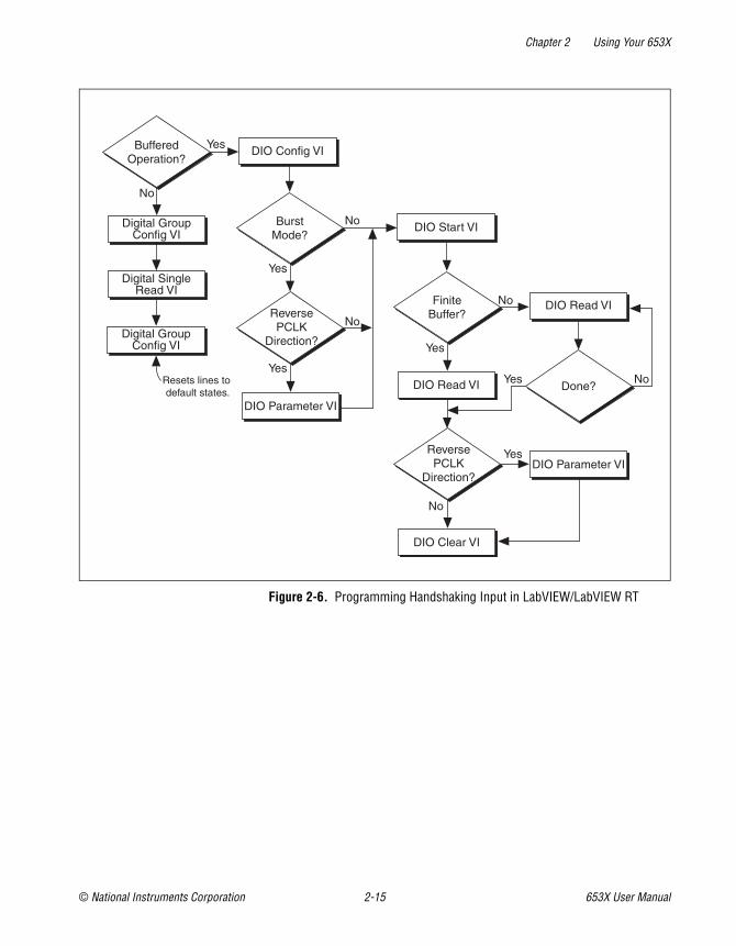
Creating a ProgramUsing the following flowcharts as a guide, create a program to perform handshaking I/O. Figures 2-4 and 2-5 display flowcharts for C programming using NI-DAQ, while Figures 2-6 and 2-7 show a LabVIEW programming flowcharts.
The boxes represent function names for the appropriate software, and the diamonds represent decision points.

Chapter 2 Using Your 653X
© National Instruments Corporation 2-13 653X User Manual
Figure 2-4. Programming Buffered Handshaking I/O in NI-DAQ
Read?DIG_Grp_Mode
DIG_Grp_Config
Read?
Continuous?
No
DIG_DB_ConfigYes
DIG_Block_In
DIG_Block_Out
DIG_Block_In
DIG_Block_Out
Yes
No
Yes
No
Yes
DIG_DB_HalfReadyIs the
next half bufferready?
DIG_DB_Transfer
AcquisitionComplete?
Yes
No
No
DIG_Block_ClearYes
DIG_Block_Check
No AcquisitionComplete?

Chapter 2 Using Your 653X
653X User Manual 2-14 ni.com
Figure 2-5. Programming Unbuffered Handshaking I/O in NI-DAQ
DIG_Grp_Config
Input?
DIG_Grp_Mode
DIG_Grp_Status
Ready?
DIG_In_Grp
DIO_Grp_Config
Done?
DIG_Out_Grp
DIG_Grp_Status
Ready?
Done?
DIG_In_Grp
DIO_Grp_Config*
No
Yes
No
Yes
No
Yes Yes
No
Yes
No
*Clear Configuration
Chapter 2 Using Your 653X
© National Instruments Corporation 2-15 653X User Manual
Figure 2-6. Programming Handshaking Input in LabVIEW/LabVIEW RT
DIO Start VI
DIO Parameter VI
DIO Clear VI
BufferedOperation?
DIO Config VIYes
BurstMode?
No
No
No
ReversePCLK
Direction?
Yes
Yes
FiniteBuffer?
DIO Read VI
Yes
Done?
DIO Read VI
Yes
No
No
Digital SingleRead VI
No
ReversePCLK
Direction?
YesDIO Parameter VI
Digital GroupConfig VI
Resets lines to default states.
Digital GroupConfig VI

Chapter 2 Using Your 653X
653X User Manual 2-16 ni.com
Figure 2-7. Programming Handshaking Output in LabVIEW/LabVIEW RT
By default, for output buffered transfers the 6534 device will preload the on board memory with data before starting the output operation. This is done to eliminate or reduce the impact of the PCI bus bandwidth limitations and increase the overall transfer rate.
DIO Start VI
DIO Parameter VI
DIO Clear VI
BufferedOperation?
DIO Config VIYes
BurstMode?
No
No
No
ReversePCLK
Direction?
Yes
Yes
FiniteBuffer?
DIO Wait VI
Yes
Done?
DIO Write VI
Yes
No
No
DIO Write VI
Digital SingleWrite VI
No
ReversePCLK
Direction?
YesDIO Parameter VI
Digital GroupConfig VI
Resets the linesto default states.
Digital GroupConfig VI

Chapter 2 Using Your 653X
© National Instruments Corporation 2-17 653X User Manual
The preloading process will cause a small delay between the start command in software and the actual start of data transfer. If this is a concern, you may disable the preloading by calling the following function/VI before the software start command:
• NI-DAQ C interface—In the Set_DAQ_Device_Info function, set the ND_FIFO_Transfer_COUNT to ND_NONE.
• LabVIEW—In the DIO Parameter VI, set the Scarabs Preload Enable attribute to OFF.
Generating and Receiving Digital Patterns and Waveforms—Pattern I/O
Using pattern I/O, you can acquire or generate patterns on every rising or falling edge of a clock signal. The clock signal can be generated internally by an onboard 32-bit counter set to a user-specified frequency or the clock signal can be received from the REQ pin in the I/O connector.
Note Feed external clocking signals into the PCLK pin for burst-mode handshaking and into the REQ pin when performing pattern I/O.
Deciding the Width of Data to TransferYou can choose between a width of eight, 16, or 32 bits. Use the following table to find the valid combinations of ports and timing controllers you can use based on the width of data you want to transfer.
Table 2-3. Port and Timing Controller Combinations
Transfer Width
Possible Port Combinations
Timing Controllers That Can Be Used
8 bits Port 0 (DIOA<0..7>) Group 1
Port 2 (DIOC<0..7>) Group 2
16 bits Port 0, Port 1 Group 1
Port 2, Port 3 Group 2
32 bits Port 0, Port 1, Port 2, Port 3 Group 1

Chapter 2 Using Your 653X
653X User Manual 2-18 ni.com
Deciding Transfer DirectionYou can choose to send data from your 653X device to the peripheral device (output), or from the peripheral device to your 653X device (input).
Choosing an Internal or External REQ SourceIn pattern I/O, the 653X device acquires/generates data on every falling or rising edge (programmable) of the REQ signal. The REQ signal can be generated internally or based on the clock of a peripheral device. An example of using external REQ is sharing a sample clock of an analog input device so you can synchronize the analog and digital operations.
Deciding the REQ PolarityBy default, data from an external REQ source is transferred on the rising edge of the signal and on the falling edge of the internal REQ source. You can reverse the REQ polarity by using the following functions:
• NI-DAQ C interface—Specify the REQ polarity in the DIG_Group_Mode function before calling the DIG_Block_PG_Config function.
• LabVIEW—Specify the REQ polarity in the Digital Mode Config VI that is called by the DIO Config VI.
Note For more information on LabVIEW VIs and NI-DAQ functions, consult the LabVIEW Help and the NI-DAQ Function Reference Help.
Refer to Table C-1, 653X I/O Connector 68-Pin Assignments, for an overview of all control/timing trigger lines.
Deciding the Transfer RateIf you are generating the REQ signal internally, you need to specify the rate of data transfer. The transfer rate is specified in software by using two parameters, the timebase frequency and timebase divisor:
where
timebase frequency = 20 MHz, 10 MHz, 1 MHz, 100 kHz, 10 kHz, 1 kHz, or 100 Hz, and
timebase divisor = an integer between 1 and 65,355.
transfer rate (Hz)timebase frequency
timebase divisor----------------------------------------------=

Chapter 2 Using Your 653X
© National Instruments Corporation 2-19 653X User Manual
For example, if you specify a timebase of 100 kHz and a timebase divisor of 25, the resulting acquisition/generation rate would be 4 kHz. 100 kHz/25 = 4 kHz.
Note If you are using a version of NI-DAQ prior to version 6.8, the minimum value for timebase divisor is 2.
Note In LabVIEW, you can specify the transfer rate directly using the Digital Clock Config VI (called by the DIO Start VI). The software will choose the closest transfer rate by selecting the frequency and divisor. To see the actual transfer rate, create an indicator at the actual clock frequency output of the Digital Clock Config VI.
Deciding How to Start and Stop Data Transfer—TriggeringBy default, data transfer starts upon a software command (the Digital Buffer Control VI called by the DIO Start VI in LabVIEW and the DIG_Block_In and DIG_Block_Out functions in NI-DAQ C interface). However, you have the option of using a hardware trigger to start, stop, or start and stop data transfer.
The three types of trigger signals available are the start trigger, the stop trigger, or the start and stop trigger.
Start TriggerA start trigger is a trigger that initiates a pattern I/O upon receipt of a hardware trigger on the ACK (STARTTRIG) pin.
Figure 2-8. Starting Data Transfer Using a Trigger
Stop TriggerWhen using a stop trigger, transfer starts upon a software command. Once a hardware trigger is received on the STOPTRIG pin, a predetermined amount of pretrigger and posttrigger data is saved in the buffer. Once this
REQ
ACK (STARTTRIG)
Posttrigger Data

Chapter 2 Using Your 653X
653X User Manual 2-20 ni.com
data is in the buffer, transfer stops. If the stop trigger arrives before all the pretrigger data is acquired, NI-DAQ returns an error.
Figure 2-9. Stopping Data Transfer Using a Trigger
Start and Stop TriggerWhen using a start and stop trigger, transfer starts upon receiving a trigger on the start trigger line (ACK/STARTTRIG pin) and ends upon receiving a trigger on the stop trigger line (STOPTRIG pin) and a predetermined amount of pretrigger and posttrigger data is saved in the buffer. If a stop trigger is received before a start trigger, it is ignored. If the stop trigger arrives before all the pretrigger data is acquired, NI-DAQ returns an error.
Figure 2-10. Using a Start and Stop Trigger
Pattern-Matching Trigger (Input Only)Instead of using an external signal on the start/stop trigger pins on the I/O connector, you may start or stop (not both) an operation once a user-specified digital pattern is matched or not matched.
Specify four parameters to set up a pattern-matching trigger:
• Whether it is a start or stop trigger
• The data pattern to be detected/matched
• The mask, which selects the bits of interest for pattern comparison (0 for bits not of interest)
REQ
STOPTRIG
Pretrigger Data Posttrigger Data
REQ
STOPTRIG
ACK (STARTTRIG)
Pretrigger Data Posttrigger Data

Chapter 2 Using Your 653X
© National Instruments Corporation 2-21 653X User Manual
• The polarity (whether to trigger on data that matches or mismatches the specified pattern)
For example, if you want to start acquisition when the two least significant bits of your data are 1 and 0, you would specify your trigger parameters to match those in Figure 2-11.
Figure 2-11. Pattern-Matching Trigger Example
Tip To prevent a transient data value during line switching from falsely causing a match, set a valid pattern for at least 60 ns to guarantee detection. In addition, keep glitches to less than 20 ns to guarantee rejection.
Choosing Continuous or Finite Data TransferYou can transfer data continuously into or from computer memory or specify the number of points you want to transfer.
Finite TransfersFor finite transfers, the 653X device transfers the specified amount of data to/from computer memory and stops the operation.
Continuous InputFor continuous input, the 653X device transfers input data to the computer memory buffer continuously. As the device is filling the buffer, call the DIG_DB_Transfer function or the DIO Read VI to retrieve the data. If at any time the device runs out of space in the buffer, it stops the operation and NI-DAQ returns an error.
You have the option to allow the device to continue when it runs out of buffer space and overwrite data you have not yet read. You can specify this through the oldDataStop parameter in the DIG_DB_Config function and
X X X X X X 1 0
0 0 0 0 0 0 1 1
Postive: Search for Match
Pattern to Detect
Mask
Polarity

Chapter 2 Using Your 653X
653X User Manual 2-22 ni.com
the Data Overwrite/Regenerate parameter in the Digital Buffer Control VI, called by the DIO Start VI.
Continuous OutputSimilarly, with continuous output, the 653X device continuously reads data from computer memory. As the device retrieves data from the buffer, call the DIG_DB_Transfer function or the DIO Write VI to write the data. The device will stop and return an error if it runs out of data to output, but you have the option to allow it to regenerate data that has already been outputted. As in continuous input, you specify the device to allow regeneration with the oldDataStop parameter in the DIG_DB_Config function and the data overwrite/regenerate parameter in the Digital Buffer Control VI, called by the DIO Start VI.
With 6534 devices, if you want to output the same block of data repeatedly, you have the option of loading a buffer of data into onboard memory and looping through this data block continuously. With this option, data is only transferred from computer memory to the device onboard memory once, and the device outputs the same block of data continuously from its onboard memory. This allows the device to output data at higher rates because it is not limited by the PCI bus bandwidth. To enable on-oard memory looping:
• NI-DAQ C interface—Set the ND_PATTERN_GENERATION_LOOP_ENABLED to ND_ON in the Set_DAQ_Device_Info function.
• LabVIEW—Set the Pattern Generation Loop Enable attribute to ON in the DIO Parameter VI.
Choosing DMA or Interrupt TransfersWhen using DMA (by default), the 6534 device transfers data in 32-byte blocks and the 6533 device transfers data in 4-byte blocks. Therefore, at any time during a continuous operation, there may be up to 31 bytes (or 3 bytes for 6533 devices) of data in an internal device FIFO. You can use interrupt driven transfers if you need to retrieve data immediately as it is acquired. Interrupt driven transfers are slower and take more processing time from the computer than DMA driven transfers.

Chapter 2 Using Your 653X
© National Instruments Corporation 2-23 653X User Manual
Monitoring Data TransferTo monitor your data transfer once data transfer starts:
• NI-DAQ C interface—Call DIG_Block_Check to monitor finite data transfer. For continuous transfers, use Get_DAQ_Device_Info to obtain the cumulative transfer count (DIG_Block_Check does not return the number of buffer iterations completed). The following table lists the attribute types and values returned for Get_DAQ_Device_Info:
Note You should always read the least significant bits of the transfer count before reading the most significant bits. The 32 most significant bits of the transfer count is cached in software when you read the least significant bits.
• LabVIEW—Use the Digital Buffer Write VI or the Digital Buffer Read VI, which are called by the DIO Read VI, the DIO Write VI, and the DIO Wait VI.
Connecting SignalsConnect digital input signals to the I/O connector using the pinout diagrams, Figures C-1, 653X I/O Connector 68-Pin Assignments, or C-2, 68-to-50-Pin Adapter Pin Assignments.
If you are using an external source for your REQ signal, connect it to the appropriate REQ pin of the I/O connector.
Transfer Direction Attribute Value Returned
Input ND_READ_MARK_H_SNAPSHOT_GR1 Most significant 32-bit of transfer count
ND_READ_MARK_H_SNAPSHOT_GR1
ND_READ_MARK_L_SNAPSHOT_GR1 Least significant 32-bit of transfer count
ND_READ_MARK_L_SNAPSHOT_GR2
Output ND_WRITE_MARK_H_SNAPSHOT_GR1 Most significant 32-bit of transfer count
ND_WRITE_MARK_H_SNAPSHOT_GR2
ND_WRITE_MARK_L_SNAPSHOT_GR1 Least significant 32-bit of transfer count
ND_WRITE_MARK_L_SNAPSHOT_GR2

Chapter 2 Using Your 653X
653X User Manual 2-24 ni.com
If you are using external start and/or stop triggers, connect to the appropriate pins—start trigger (ACK/STARTTRIG) and/or stop trigger (STOPTRIG).
Creating a ProgramUsing the following flowcharts as a guide, create a program to perform pattern I/O. Figures 2-13 and 2-14 display flowcharts for C programming using NI-DAQ, while Figure 2-14 shows a LabVIEW programming flowchart.
The boxes represent function names for the appropriate software, and the diamonds represent decision points.
Figure 2-12. Programming Pattern I/O (Single Buffer) in NI-DAQ
DIG_Block_Check
DIG_Block_Clear
Yes
AcquisitionComplete?
No
DIG_Grp_Config
DIG_Trigger_Config
DIG_Block_In
DIG_Block_Out
DIG_Block_PG_Config
Trigger?
Yes
No
Yes
NoRead?

Chapter 2 Using Your 653X
© National Instruments Corporation 2-25 653X User Manual
Figure 2-13. Programming Pattern I/O (Continuous) in NI-DAQ
Figure 2-14. Programming Pattern I/O in LabVIEW/LabVIEW RT
DIG_DB_HalfReadyIs the
next half bufferready?
DIG_DB_Transfer
DIG_Block_Clear
AcquisitionComplete?
Yes
Yes
No
NoYes
No
DIG_Block_In
DIG_Block_Out
DIG_Grp_Config
DIG_Trigger_Config
DIG_DB_Config
DIG_Block_PG_Config
Trigger?
Yes
No
Read?
Trigger? Done?
DIO Read/Write VI
DIO Start VI
DIO Clear VI
No
Yes
Yes
No
DIO Config VI
Write?
DIO Write VI
No
Yes
Trigger?
NoDigital Trigger Config VI
Digital Trigger Config VI
Yes

Chapter 2 Using Your 653X
653X User Manual 2-26 ni.com
Note If you are performing a finite pattern output operation, you can call the DIO Wait VI instead of the DIO Write VI after the DIO Start VI. For more information about these VIs, see the LabVIEW Help.
By default, for output buffered transfers the 6534 device will preload the on board memory with data before starting the output operation. This is done to eliminate or reduce the impact of the PCI bus bandwidth limitations and increase the overall transfer rate. The preloading process will cause a small delay between the start command in software and the actual start of data transfer. If this is a concern, you may disable the preloading by calling the following function/VI before the software start command:
• NI-DAQ C interface—In the Set_DAQ_Device_Info function, set the ND_FIFO_TRANSFER_COUNT to ND_NONE.
• LabVIEW—In the DIO Parameter VI, set the Scarabs Preload Enable attribute to OFF.
Monitoring Line State—Change DetectionYou can configure your 653X device to acquire data whenever the state of one or more data lines change. Once the 653X device detects a change in one of the selected lines, it will capture data within 50–150 ns and outputs a pulse on the REQ pin. This mode increases CPU and bus efficiency because you can monitor activity on input lines without continuously polling or transferring unnecessary data during periods of inactivity.
Tip The 653X device used alone will detect if a change occurred, but if used in conjunction with a 660X device (via a RTSI line), the relative time between changes can be acquired by the 660X device.
Deciding the Width of Data to AcquireYou can choose between a width of eight, 16, or 32 bits. Use the following table to find the valid combinations of ports and timing controllers you can use based on the width of data you want to acquire.
Table 2-4. Port and Timing Controller Combinations
Transfer Width
Possible Port Combinations
Timing Controllers That Can Be Used
8 bits Port 0 (DIOA<0..7>) Group 1
Port 2 (DIOC<0..7>) Group 2

Chapter 2 Using Your 653X
© National Instruments Corporation 2-27 653X User Manual
Deciding Which Lines You Want to MonitorYou need to specify which of the lines in your acquisition you want to monitor for changes.
Specify which bits are significant to you by using a software line mask in the DIG_Trigger_Config function in NI-DAQ C interface, and the Digital Trigger Config VI for LabVIEW. In the following example, the user specifies the mask to detect changes on the two least-significant bits of a port. Pattern 1 does not have changes in the two bits of interest and data is not latched, but for pattern 2, a change is detected on one of the two bits of interest, and the value of the entire port is acquired.
Figure 2-15. Change Detection Example Settings
Deciding How to Start and Stop Data Transfer—TriggeringBy default, data transfer starts upon a software command (the Digital Buffer Control VI called by the DIO Start VI in LabVIEW and the DIG_Block_In and DIG_Block_Out functions in NI-DAQ C interface). However, you have the option of using a hardware trigger to start, stop, or start and stop data transfer.
16 bits Port 0, Port 1 Group 1
Port 2, Port 3 Group 2
32 bits Port 0, Port 1, Port 2, Port 3 Group 1
Mask 0 0 0 0 0 0 1 1
Initial Input Pattern
0 0 0 0 0 0 1 0
Input Pattern 1 0 1 0 0 0 0 1 0 No change on specified bits. Data is not latched.
Input Pattern 2 0 0 0 0 0 0 1 1 Change detected, latch entire port.
Table 2-4. Port and Timing Controller Combinations (Continued)
Transfer Width
Possible Port Combinations
Timing Controllers That Can Be Used

Chapter 2 Using Your 653X
653X User Manual 2-28 ni.com
The three types of trigger signals available are the start trigger, the stop trigger, or the start and stop trigger.
Start TriggerA start trigger is a trigger that initiates a pattern I/O upon receipt of a hardware trigger on the ACK (STARTTRIG) pin.
Figure 2-16. Starting Data Transfer Using a Trigger
Stop TriggerWhen using a stop trigger, transfer starts upon a software command. Once a hardware trigger is received on the STOPTRIG pin, a predetermined amount of pretrigger and posttrigger data is saved in the buffer. Once this data is in the buffer, transfer stops. If the stop trigger arrives before all the pretrigger data is acquired an error will return in software.
Figure 2-17. Stopping Data Transfer Using a Trigger
Start and Stop TriggerWhen using a start and stop trigger, transfer starts upon receiving a trigger on the start trigger line (ACK/STARTTRIG pin) and ends upon receiving a trigger on the stop trigger line (STOPTRIG pin) and a predetermined amount of pretrigger and posttrigger data is saved in the buffer. If a stop trigger is received before a start trigger, it is ignored. If the stop trigger arrives before all the pretrigger data is acquired an error will return in software.
REQ
ACK (STARTTRIG)
Posttrigger Data
REQ
STOPTRIG
Pretrigger Data Posttrigger Data

Chapter 2 Using Your 653X
© National Instruments Corporation 2-29 653X User Manual
Figure 2-18. Using a Start and Stop Trigger
Pattern-Matching TriggerInstead of using an external signal on the start/stop trigger pins on the I/O connector, you may start or stop (not both) an operation once a user-specified digital pattern is matched.
Specify four parameters to set a pattern-matching trigger:
• Whether it is a start or stop trigger
• The data pattern to be detected/matched
• The mask, which selects the bits of interest for pattern detection
Note The mask for the pattern-matching trigger is the same as the one used for change detection. In other words, input lines significant for the pattern-matching trigger are also significant for change detection.
• Polarity (whether to detect data that matches or mismatches the specified pattern)
The 653X device detects any occurrence of a specific pattern immediately as the data comes in. When a match occurs, the 653X device starts acquiring data. For example, if you want to start an acquisition when the two least significant bits of your data are 1 and 0, you would specify your trigger parameters to match those in Figure 2-19.
REQ
STOPTRIG
ACK (STARTTRIG)
Pretrigger Data Posttrigger Data

Chapter 2 Using Your 653X
653X User Manual 2-30 ni.com
Figure 2-19. Pattern-Detection Trigger Example
Tip To prevent a transient data value during line switching from falsely causing a match, set a valid pattern for at least 60 ns to guarantee detection. In addition, keep glitches to less than 20 ns to guarantee rejection.
Choosing Continuous or Finite Data TransferYou can acquire data continuously into or from computer memory or specify the number of points you want to transfer.
Finite TransfersFor finite transfers, the 653X device inputs the specified amount of data to a computer memory buffer and stops the operation.
Continuous InputFor continuous input, the 653X device transfers input data to the computer memory buffer continuously. As the device is filling the buffer, call the DIG_DB_Transfer function or the DIO Read VI to retrieve the data. If at any time the device runs out of space in the buffer, it stops the operation and NI-DAQ returns an error.
You have the option to allow the device to continue when it runs out of buffer space and overwrite data you have not yet read. You can specify this through the oldDataStop parameter in the DIG_DB_Config function and the Data Overwrite/Regenerate parameter in the Digital Buffer Control VI, called by the DIO Start VI.
X X X X X X 1 0
0 0 0 0 0 0 1 0
0 0 0 0 0 0 1 1
Postive: Search for Match
Value to Detect
Pattern
Mask
Polarity

Chapter 2 Using Your 653X
© National Instruments Corporation 2-31 653X User Manual
Choosing DMA or Interrupt TransfersWhen using DMA (by default), the 6534 device transfers data in 32-byte blocks and the 6533 device transfers data in 4 byte blocks. Therefore, at any time during a continuous operation, there may be up to 31 bytes (or 3 bytes for 6533 devices) of data in an internal device FIFO. You can use interrupt driven transfers if you need to retrieve data immediately as it is acquired. Interrupt driven transfers are slower and take more processing time from the computer than DMA driven transfers.
Connecting SignalsConnect digital input signals to the I/O connector using the pinout diagrams, Figures C-1, 653X I/O Connector 68-Pin Assignments, or C-2, 68-to-50-Pin Adapter Pin Assignments.
If you are using external start and/or stop triggers, connect to the appropriate pins—start trigger (ACK or STARTTRIG) and/or stop trigger (STOPTRIG).
Creating a ProgramUsing the following flowcharts as a guide, create a program to perform change detection. Figure 2-21 and 2-22 display flowcharts for C programming using NI-DAQ, while Figure 2-22 shows a LabVIEW programming flowchart.
The boxes represent function names for the appropriate software, and the diamonds represent decision points.

Chapter 2 Using Your 653X
653X User Manual 2-32 ni.com
Figure 2-20. Programming Change Detection (Continuous) in NI-DAQ
Figure 2-21. Programming Change Detection (Single Buffer) in NI-DAQ
DIG_DB_HalfReadyIs the
next half bufferready?
DIG_DB_Transfer
DIG_Block_Clear
AcquisitionComplete?
Yes
Yes
No
NoDIG_Grp_Config
DIG_Trigger_Config DIG_DB_Config
DIG_Block_PG_Config
DIG_Block_In
Specify data mask here
DIG_Block_Check
DIG_Block_Clear
Yes
AcquisitionComplete?
No
DIG_Grp_Config
DIG_Trigger_Config DIG_Block_In
DIG_Block_PG_Config
Specify data mask here

Chapter 2 Using Your 653X
© National Instruments Corporation 2-33 653X User Manual
Figure 2-22. Programming Change Detection for LabVIEW/LabVIEW RT
DIO Config VI
Trigger Config VI
DIO Read VI
Done?
DIO Clear VI
Yes
No
DIO Start VI
Specify data mask here
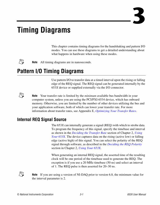
© National Instruments Corporation 3-1 653X User Manual
3Timing Diagrams
This chapter contains timing diagrams for the handshaking and pattern I/O modes. You can use these diagrams to get a detailed understanding about what happens in hardware when using these modes.
Note All timing diagrams are in nanoseconds.
Pattern I/O Timing DiagramsUse pattern I/O to transfer data at a timed interval upon the rising or falling edge of the REQ signal. The REQ signal can be generated internally by the 653X device or supplied externally via the I/O connector.
Note Your transfer rate is limited by the minimum available bus bandwidth in your computer system, unless you are using the PCI/PXI-6534 device, which has onboard memory. Otherwise, you are limited by the number of other devices utilizing the bus and your application software, both of which can lower your transfer rate. For more information about transfer rates, see Appendix E, Optimizing Your Transfer Rates.
Internal REQ Signal SourceThe 653X can internally generate a signal (REQ) with which to strobe data. To program the frequency of this signal, specify the timebase and interval as shown in the Deciding the Transfer Rate section of Chapter 2, Using Your 653X. The device captures data on the rising (active low) or falling edge (active high) of this signal. You can select the polarity of the REQ signal through software, as described in the Deciding the REQ Polarity section in Chapter 2, Using Your 653X.
When generating an internal REQ signal, the asserted time of the resulting clock will be one period of the timebase used to generate the REQ. The exception is if you use a 20 MHz timebase (50 ns) and select an interval of 1. The REQ pulse is then asserted for 20–30 ns.
Note If you are using a version of NI-DAQ prior to version 6.8, the minimum value for the interval parameter is 2.

Chapter 3 Timing Diagrams
653X User Manual 3-2 ni.com
Figure 3-1. Internal Request Timing Diagram
External REQ Signal SourceUse an external request when you want to time data transfers using anexternal signal on the REQ pin of the I/O connector. You can select thepolarity of the REQ signal. If active high (default), the 653X device willlatch the data on the I/O pins on the rising edge of the REQ signal. If activelow, the 653X device will latch the data on the I/O pins on the falling edgeof the REQ signal. The low time and high time of the REQ signal must eachbe >20 ns. The minimum duration for a period of the REQ signal is 50 ns.
Note For data transfers that use a hardware start trigger, there is no mandatory setup (tsu)or hold time (th) for the STARTRIG (ACK) signal. It can be asserted at any point before,
Parameter Description
tc* Cycle time
tw* Width of pulse
tp Propagation time to valid output data
tsu Setup time
th Hold time
* The 6534 devices will transfer data at 20 MHz when the cycle time (tc) for REQ pulse is 50 ns and width of the REQpulse (tw) is 20–30 ns.
dtp will remove bar
Data Valid(Output Mode)
Data Valid(Input Mode)
tsu
30 nsMin
th0 nsMin
tp30 nsMax
tc
Programmable = Interval x Timebase
Programmable = One Timebase
REQ if Active High
REQ if Active Low
tw

Chapter 3 Timing Diagrams
© National Instruments Corporation 3-3 653X User Manual
during, or after the REQ edge. If STARTRIG is asserted too close to the REQ edge, it may not be recognized until the next REQ edge. To avoid this uncertainty, you can observe an optional setup time of 15 ns, in other words, assert STARTRIG at least 15 ns before the start of the REQ pulse.
The STARTRIG signal is synchronized to the REQ edge using a flip-flop. Because of this synchronization flip-flop, there is a one REQ-pulse delay after STARTRIG before the data capture begins. There is a possibility of a two-cycle delay if you do not observe the optional setup time mentioned in the previous note.
Figure 3-2. External Request Timing Diagram
Parameter Description
tc Cycle time
thw Width of low pulse
tp Propagation time to valid output data
tsu Setup time
th Hold time
Data Valid(Output Mode)
Data Valid(Input Mode)
REQ
thtsu
10 nsMin
20 nsMin
tp30 ns Max
thw20 ns Min 20 ns Min
tc50 ns Min
tw

Chapter 3 Timing Diagrams
653X User Manual 3-4 ni.com
Handshaking I/O Timing DiagramsThis section compares of the handshaking I/O protocols and includes timing diagrams for each:
• Handshaking sequence for input operation
• State machine for input operation
• Timing specification for input operation
• Handshaking sequence for output operation
• State machine for output operation
• Timing specification for output operation
Comparing the Different Handshaking ProtocolsFor an overview of all handshaking protocols supported by your 653X device, see Table 3-1.
Note Whether an ACK or a REQ signal occurs first in the handshaking sequence depends on the protocol and the direction of the transfer.
Table 3-1. Handshaking Protocol Characteristics
Protocol
REQ/ACK
PolarityWhich REQ Edge Requests Transfer
Where the Programmable
Delay Is Located Complementary Protocol(s)
Asynchronous Protocols
8255 Emulation
Active-low Trailing Between transfers Long Pulse
Level ACK Programmable Leading Before ACK and between transfers
Level ACK
Leading-Edge Programmable Leading Before ACK and between transfers
Leading Edge
Long Pulse Programmable Leading Pulse width and between transfers
Long Pulse, 8255 Emulation, and 8255
Trailing-Edge Programmable Trailing Pulse width and between transfers
Trailing-Edge

Chapter 3 Timing Diagrams
© National Instruments Corporation 3-5 653X User Manual
In order for the 653X device to communicate with peripheral devices in handshaking mode, it is important to verify that:
• You are using complementary protocols. For example, use 8255-emulation protocol with long-pulse protocol.
• The ACK/REQ polarity are the same. For example, 8255 emulation is active low only, so the other device must use the long-pulse protocol and have active low ACK/REQ polarity.
Using the Burst ProtocolBurst protocol is a synchronous, or clocked, protocol. In addition to using the ACK and REQ signals like the other handshaking protocols, in burst protocol, the 653X device and the peripheral device share a clock signal over the PCLK line.
The 653X device asserts the ACK signal if it is ready to perform a transfer. If the peripheral device also asserts the REQ signal indicating it is ready, a transfer occurs on the rising edge of the PCLK signal. See Figures 3-3 and 3-4 for examples of burst protocol transfers. Dashed lines indicate when data is transferred.
Synchronous Protocol
Burst Programmable Neither (level REQ) Clock speed Burst
* Asynchronous protocols can compensate automatically to cable length, yet for synchronous protocols, you need to select an appropriate speed for your cable when configuring your device.
Select a delay of at least the following:
• 0 for a typical cable up to 1 m
• 1 (70 ns) for a typical cable up to 5 m
• 2 (140 ns) for a typical cable up to 15 m long
Table 3-1. Handshaking Protocol Characteristics (Continued)
Protocol
REQ/ACK
PolarityWhich REQ Edge Requests Transfer
Where the Programmable
Delay Is Located Complementary Protocol(s)
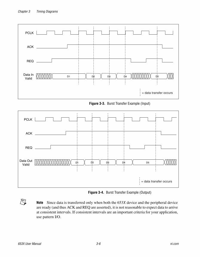
Chapter 3 Timing Diagrams
653X User Manual 3-6 ni.com
Figure 3-3. Burst Transfer Example (Input)
Figure 3-4. Burst Transfer Example (Output)
Note Since data is transferred only when both the 653X device and the peripheral device are ready (and thus ACK and REQ are asserted), it is not reasonable to expect data to arrive at consistent intervals. If consistent intervals are an important criteria for your application, use pattern I/O.
PCLK
ACK
Data InValid
REQ
D5D1 D2 D3 D4
= data transfer occurs
PCLK
ACK
REQ
Data OutValid
D1 D2 D3 D4 D5
= data transfer occurs

Chapter 3 Timing Diagrams
© National Instruments Corporation 3-7 653X User Manual
The 653X device can either drive an output clock signal onto the PCLK line or receive an input clock signal from the PCLK line. By default, the PCLK line is set for input during output transfers, and set for output during input transfers.
Tip If you are using long cables, slow down the PCLK clock signal to compensate for the decrease in data setup time.

Chapter 3 Timing Diagrams
653X User Manual 3-8 ni.com
Figure 3-5. Burst Input Timing Diagram (Default)
Parameter Description Minimum Maximum
Input Parameters
trs Setup time from REQ valid to PCLK 12 —
trh Hold time from PCLK to REQ invalid 0 —
tdis Setup time from input data valid to PCLK 4 —
tdih Hold time from PCLK to input data invalid 6 —
Output Parameters
tpc PCLK cycle time 50 7001
tpw PCLK high pulse duration tpc/2 – 5 tpc/2 + 5
tpa PCLK to ACK valid — 18
tah Hold time from PCLK to ACK invalid 3 —1 tpc = programmable delay from 100 to 700 ns, or 50 ns if programmable delay is 0. Timebase stability for the onboard 20 MHz clock source is 100 ppm.
All timing values are in nanoseconds.
PCLK
ACK
Data In Valid
REQ
tdis tdih
trs
tpa
tpw
tpc
trh
tah

Chapter 3 Timing Diagrams
© National Instruments Corporation 3-9 653X User Manual
Figure 3-6. Burst Output Timing Diagram (Default)
Parameter Description Minimum Maximum
Input Parameters
tpc PCLK cycle time 50 —
tpw PCLK high pulse duration 20 —
tpl PCLK low pulse duration 20 —
trs Setup time from REQ valid to PCLKfalling edge
1 —
trh Hold time from PCLK to REQ invalid 0 —
Output Parameters
tpa PCLK to ACK valid — 22
tah Hold time from PCLK to ACK invalid 3 —
tpdo PCLK to output data valid — 28
tdoh Hold time from PCLK to output datainvalid
5 —
All timing values are in nanoseconds.
PCLK
ACK
Data Out Valid
REQ
trs
tpa
tpdo
tpw tpl
tpc
trh
tah
tdoh

Chapter 3 Timing Diagrams
653X User Manual 3-10 ni.com
Figure 3-7. Burst Input Timing Diagram (PCLK Reversed)
Parameter Description Minimum Maximum
Input Parameters
tpc PCLK cycle time 50 —
tpw PCLK high pulse duration 20 —
tpl PCLK low pulse duration 20 —
trs Setup time from REQ valid to PCLK falling edge
1 —
trh Hold time from PCLK to REQ invalid 0 —
tdis Setup time from input data valid to PCLK falling edge
0 —
tdih Hold time from PCLK to input data valid 0 —
Output Parameters
tpa PCLK to ACK valid — 22
tah Hold time from PCLK to ACK invalid 3 —
All timing values are in nanoseconds.
PCLK
ACK
Data In Valid
REQ
tdis tdih
trs
tpa
tpw tpl
tpc
trh
tah

Chapter 3 Timing Diagrams
© National Instruments Corporation 3-11 653X User Manual
Figure 3-8. Burst Output Timing Diagram (PCLK Reversed)
Parameter Description Minimum Maximum
Input Parameters
trs Setup time from REQ valid to PCLK 12 —
trh Hold time from PCLK to REQ invalid 0 —
Output Parameters
tpc PCLK cycle time 50 7001
tpw PCLK high pulse duration tpc/2 – 5 tpc/2 + 5
tpa PCLK to ACK valid — 18
tah Hold time from PCLK to ACK invalid 3 —
tpdo PCLK to output data valid — 28
tdoh Hold time from PCLK to output data invalid
4 —
tdis Setup time from input data valid to PCLK 0 —
tdih Hold time from PCLK to input data invalid 0 —1tpc = programmable delay from 100 to 700 ns, or 50 ns if programmable delay is 0. Timebase stability for the board 20 MHz clock source is 50 ppm.
All timing values are in nanoseconds.
PCLK
ACK
Data Out Valid
REQ
trs
tpa
tpdo
tpw
tpc
tdoh
trh
tah

Chapter 3 Timing Diagrams
653X User Manual 3-12 ni.com
Using Asynchronous ProtocolsAll handshaking protocols except burst are asychronous. The asynchronous protocols include 8255 emulation, level ACK, leading edge, trailing edge, and long pulse.
When using these protocols, you have the following options:
• You can change the polarity of the ACK and REQ signals (except for 8255-emulation). The diagrams in this chapter show active-high signals.
• You can set a programmable delay, from 0 to 700 ns, programmable in increments of 100 ns. Use the programmable delay to insert wait states if you have a slow peripheral device. A delay increases the duration of each transfer. The location of the delay in the handshaking sequence differs from protocol to protocol. In addition, a delay increases the minimum spacing between consecutive transfers.
• You can enable request-edge latching, where in input, the 653X device latches data in from the I/O connector on the active REQ edge before reading the data. For output, after writing the data, the 653X device latches data out of the I/O connector on the active REQ edge. The active edge of the REQ is determined (rising or falling) by the handshaking protocol and the REQ polarity.
Using the 8255-Emulation ProtocolYour 653X device can perform handshaking I/O with devices that contain the 8255 chip, including National Instruments PC-DIO-24/PnP, 650X family, and PC-DIO-96/PnP. Performing the 8255-emulation protocol with your 653X device is similar to 8255 or 82C55 Programmable Peripheral Interface (PPI).
Note The 653X devices does not emulate the bidirectional protocol of a 8255 device.
The 653X device can perform back-to-back transfers much faster than a true 8255-based device. If your peripheral device requires more time between transfers, configure the 653X device to add a data-settling delay between transfers.
Note In the 8255-emulation protocol, ACK and REQ are active low, reflected in the following timing diagrams. For all other handshaking I/O protocols, the polarity of the ACK and REQ are programmable, but are shown as active high signals in the following diagrams.

Chapter 3 Timing Diagrams
© National Instruments Corporation 3-13 653X User Manual
653X device terminology differs from 8255 terminology.
• Input—The REQ line carries the 8255 STB (Strobe) input signal, and the 653X device ACK line carries the 8255 IBF (Input Buffer Full) output signal.
• Output—The REQ line carries the 8255 ACK input signal, and the 653X device ACK line carries the 8255 OBF (Output Buffer Full) output signal.
Figure 3-9. 8255 Emulation Input Handshaking Sequence
Reference Point Action Steps
1 The 653X device asserts the ACK signal when ready to accept data.
2 The peripheral device can then strobe data into the 653X device by asserting the REQ line. This can happen before or after ACK is asserted.
3 Asserting the REQ signal causes the ACK signal to deassert.
4 Deasserting the REQ signal causes the 653X device to latch input data.
5 The 653X device reasserts the ACK signal when it has space and is ready for another input. A programmable delay can be inserted here.
ACK
REQ
1
2 4
3
5
ACK and REQ are shown as active low.Steps 1-5 are repeated for each transfer.

Chapter 3 Timing Diagrams
653X User Manual 3-14 ni.com
Figure 3-10. 8255 Emulation Input State Machine
WaitFor
Space
WaitFor
REQ
ProgrammableDelay
WaitFor
REQ
When REQ Unasserted,Latch Input Data
When 6533 Device hasspace for data, input data.
ClearACK
When REQAsserted
Initial State:ACK Set
SendACK

Chapter 3 Timing Diagrams
© National Instruments Corporation 3-15 653X User Manual
Figure 3-11. 8255 Emulation Output Handshaking Sequence
Reference Point Action Steps
1 When the 653X device has data to output, it asserts the ACK signal, then waits for the peripheral device to assert REQ to indicate it is ready to accept data
2 The peripheral device asserts a REQ signal to accept the data.
3 The peripheral device can receive the data on the falling or rising edge of the ACK signal or any time in between before the next rising edge on REQ.
4 The REQ signal edge in step 2 causes the ACK signal to return to deassert.
5 The rising REQ signal edge enables a new transfer to occur. The peripheral device should wait until it has received data before deasserting the REQ signal. The peripheral device can also wait for the ACK signal to deassert before deasserting the REQ line.
6 The 653X device reasserts the ACK signal when it has data and is ready for another output. A programmable delay can be inserted here.
ACK
REQ
1
2 5
4
6
3
ACK and REQ are shown as active low.Steps 1-6 are repeated for each transfer.

Chapter 3 Timing Diagrams
653X User Manual 3-16 ni.com
Figure 3-12. 8255 Emulation Output State Machine
WaitFor
Data
WaitFor
REQ
ProgrammableDelay
WaitFor
REQ
When REQUnasserted
When 6533 Device hasdata to output, output data.
When REQAsserted
Initial State: ACK Cleared
Output Data,Then Send ACKClear ACK

Chapter 3 Timing Diagrams
© National Instruments Corporation 3-17 653X User Manual
Figure 3-13. 8255 Emulation Output Timing Diagram
Parameter Description Minimum Maximum
Input Parameters
tr*r REQ low duration 75 —
trr* REQ high duration 75 —
ta*r ACK falling edge to REQ rising edge 0 —
tdir Input data valid to REQ rising edge 0 —
trdi REQ rising edge to input data invalid 10 —
Output Parameters
taa* ACK high duration 100 —
tr*a REQ falling edge to ACK rising edge — 150
tdoa* Output data valid to ACK falling edge 25 —
trdo REQ rising edge to output data invalid 100 —
All timing values are in nanoseconds.
REQ
ACK
Data Out Valid
Data In Valid
tdoa*
tdir
ta*r
tr*r trr*
trdi
trdo
taa*tr*a
ACK and REQ are shown as active low

Chapter 3 Timing Diagrams
653X User Manual 3-18 ni.com
Using the Level-ACK ProtocolIn level-ACK protocol, the 653X device asserts the ACK signal when ready for a transfer and holds the ACK signal level until an active-going edge occurs on the REQ line. After the REQ edge occurs, the 653X device deasserts the ACK signal until the device is ready for another transfer.
Figure 3-14. Level ACK Input Handshaking Sequence
Reference Point Action Steps
Initial State ACK is deasserted. The 653X device waits for an active REQ to indicate that the peripheral device is ready. The peripheral device may optionally drive the first data at this time. The transfer cannot begin until the peripheral asserts REQ; the peripheral may either pulse REQ, or hold REQ high until the first ACK occurs. If the peripheral pulses REQ, make sure to start the transfer on the 653X device before the pulse occurs, to avoid missing the pulse.
1 The 653X device waits until it has space for data, then it asserts ACK.
2 The peripheral device can then strobe data into the 653X device by first deasserting then asserting the REQ signal. The 653X device waits for an active-going transition on the REQ line. ACK stays asserted, indicating the 653X device is ready, until the active-going REQ occurs.
3 The active-going REQ signal edge deasserts the ACK signal and causes the 653X device to latch input data.
4 To slow down the data transfer, you can insert a programmable delay before the ACK signal is asserted.
ACK
REQ
1
2
3
4
ACK and REQ are shown as active high.Steps 1-4 are repeated for each transfer.
Initial State

Chapter 3 Timing Diagrams
© National Instruments Corporation 3-19 653X User Manual
Figure 3-15. Level ACK Input State Machine
WaitFor
Space
WaitFor
REQ
ProgrammableDelay
ProgrammableDelay
WaitFor
REQ
When REQAsserted
Clear ACK
When 6533 Device has space for data, input data.*
When REQUnasserted
Initial State: ACK Cleared
SendACK
* With REQ-edge latching enabled, the data inputis from the last active-going REQ edge.

Chapter 3 Timing Diagrams
653X User Manual 3-20 ni.com
Figure 3-16. Level ACK Input Timing Diagram
Parameter Description Minimum Maximum
Input Parameters
trr* REQ pulse width 75 —
tr*r REQ inactive duration 75 —
tar ACK to next REQ 0 —
tdir(1) Input data setup to REQ active (with REQ-edge latching)
0 —
trdi Input data hold from REQ active(with REQ-edge latching)
10 —
tdir(2) Input data setup to REQ(with REQ-edge latching disabled)
0 —
tadi Input data hold from ACK(with REQ-edge latching disabled)
0 —
Output Parameters
taa* ACK pulse width 225 —
tra* REQ to ACK inactive 100 200
All timing values are in nanoseconds.
REQ
Input Data Valid(REQ-edge
latching)
Input Data Valid(REQ-edge
latching disabled)
tr*r
tra*
tdir(2) tadi
tar
taa*
trr*
trditdir(1)
ACK
ACK and REQ are shown as active high
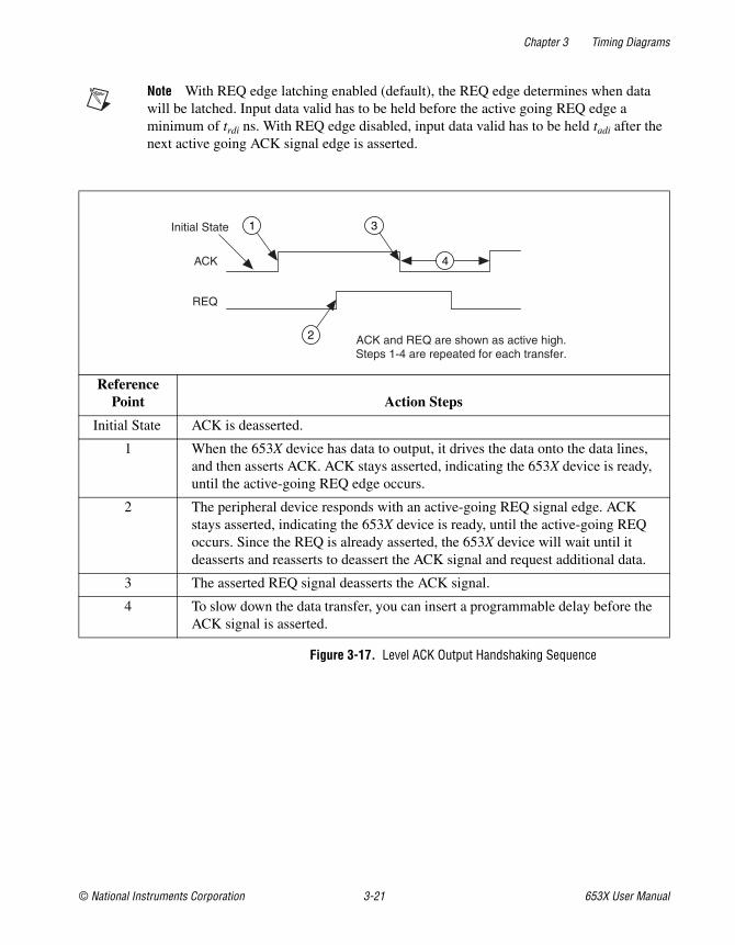
Chapter 3 Timing Diagrams
© National Instruments Corporation 3-21 653X User Manual
Note With REQ edge latching enabled (default), the REQ edge determines when data will be latched. Input data valid has to be held before the active going REQ edge a minimum of trdi ns. With REQ edge disabled, input data valid has to be held tadi after the next active going ACK signal edge is asserted.
Figure 3-17. Level ACK Output Handshaking Sequence
Reference Point Action Steps
Initial State ACK is deasserted.
1 When the 653X device has data to output, it drives the data onto the data lines, and then asserts ACK. ACK stays asserted, indicating the 653X device is ready, until the active-going REQ edge occurs.
2 The peripheral device responds with an active-going REQ signal edge. ACK stays asserted, indicating the 653X device is ready, until the active-going REQ occurs. Since the REQ is already asserted, the 653X device will wait until it deasserts and reasserts to deassert the ACK signal and request additional data.
3 The asserted REQ signal deasserts the ACK signal.
4 To slow down the data transfer, you can insert a programmable delay before the ACK signal is asserted.
ACK
REQ
1
2
3
4
ACK and REQ are shown as active high.Steps 1-4 are repeated for each transfer.
Initial State

Chapter 3 Timing Diagrams
653X User Manual 3-22 ni.com
Figure 3-18. Level ACK Output State Machine
WaitFor
Data
WaitFor
REQ
ProgrammableDelay
ProgrammableDelay
WaitFor
REQ
When REQAsserted
Clear ACK
When 6533 Device has data to output, output data.*
When REQUnasserted
Initial State: ACK Cleared
SendACK
* With REQ-edge latching enabled, the data output isdelayed until the next inactive-going REQ edge.
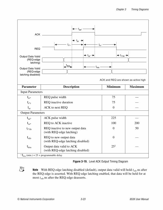
Chapter 3 Timing Diagrams
© National Instruments Corporation 3-23 653X User Manual
Figure 3-19. Level ACK Output Timing Diagram
Note With REQ edge latching disabled (default), output data valid will hold trdo ns afterthe REQ edge is asserted. With REQ edge latching enabled, that data will be held for atmost trdo ns after the REQ edge deasserts.
Parameter Description Minimum Maximum
Input Parameters
trr* REQ pulse width 75 —
tr*r REQ inactive duration 75 —
tar ACK to next REQ 0 —
Output Parameters
taa* ACK pulse width 225 —
tra* REQ to ACK inactive 100 200
tr*do REQ inactive to new output data(with REQ-edge latching)
0 50
trdo REQ to new output data(with REQ-edge latching disabled)
0 —
tdoa Output data valid to ACK(with REQ-edge latching disabled)
251 —
1 tdoa (min.) = 25 + programmable delay
REQ
Output Data Valid(REQ-edge
latching)
Output Data Valid(REQ-edge
latching disabled)
tr*r
tr*dotra*
tdoa
tar
taa*
trr*
ACK
trdo
ACK and REQ are shown as active high

Chapter 3 Timing Diagrams
653X User Manual 3-24 ni.com
Using Protocols Based on Signal EdgesThe 653X device can communicate via pulses on the ACK and REQ lines. The three edge protocols are:
• Trailing-edge protocol—The trailing edge of the ACK or REQ pulse indicates that the 653X device or peripheral device is ready for a transfer.
• Leading-edge protocol—The rising edge of the ACK or REQ pulse indicates that the 653X device or peripheral device is ready for a transfer
• Long-pulse protocol—This is a variant of the leading-edge protocol, with the additional option of using a data-settling delay. If your application requires a large minimum pulse width, you would want to use this protocol. In this case, the programmable delay is used to increase the ACK pulse width instead of delaying the ACK pulse.
You can also use long-pulse protocol to handshake with an actual 8255 or 82C55 PPI. You must set the ACK and REQ signals to active low and select a minimum pulse width of 500 ns for your 8255 or 82C55.

Chapter 3 Timing Diagrams
© National Instruments Corporation 3-25 653X User Manual
Using the Trailing-Edge Protocol
Figure 3-20. Trailing Edge Input Handshaking Sequence
Figure 3-21. Trailing Edge Input State Machine
Reference Point Action Steps
Initial State ACK is deasserted. The 653X device waits for the peripheral device to pulse REQ to indicate it has data.
1 The 653X device sends an ACK pulse of programmable width when ready to receive data.
2 After receiving the trailing edge of the ACK pulse, the peripheral device can strobe data into the 653X device and pulse the REQ.
3 The 653X device sends another ACK pulse when ready for another input.
ACK
REQ
2
1
ACK and REQ are shown as active high.Steps 1-2 are repeated for each transfer.
3
Initial State
Data Latched
WaitFor
Space
WaitFor
REQ
ProgrammableDelay
ProgrammableDelay
WaitFor
REQ
When REQUnasserted
When 6533 Devicehas space for data,
input data.*
ClearACK
When REQAsserted
SendACK
Initial State: ACK Cleared
* With REQ-edge latching enabled, the data inputis from the last inactive-going REQ edge.

Chapter 3 Timing Diagrams
653X User Manual 3-26 ni.com
Figure 3-22. Trailing Edge Input Timing Diagram
Note When REQ-edge latching is enabled (default), the REQ edge determines when data will be latched. Input data valid needs to be held tr*di after the trailing edge of REQ occurs. When REQ-edge latching is disabled, input data valid needs to be held tadi after the active going edge of the ACK signal occurs.
Parameter Description Minimum Maximum
Input Parameters
trr* REQ pulse width 75 —
tr*r REQ inactive duration 75 —
tdir* Input data setup to REQ inactive(with REQ-edge latching)
0 —
tr*di Input data hold from REQ inactive(with REQ-edge latching)
10 —
tdir Input data setup to REQ(with REQ-edge latching disabled)
0 —
tadi Input data hold from ACK(with REQ-edge latching disabled)
0 —
Output Parameters
taa* ACK pulse width 2251 2752
ta*r* ACK inactive to next REQ inactive 0 —1 taa* (min.) = 225 + programmable delay2 taa*(max) = 275 + programmable delay
REQ
Input Data Valid(REQ-edge
latching)
Input Data Valid(REQ-edge
latching disabled)
tdir*
tr*r
tdir
taa* ta*r*
trr*
tr*di
ACK
tadi
ACK and REQ are shown as active high

Chapter 3 Timing Diagrams
© National Instruments Corporation 3-27 653X User Manual
Figure 3-23. Trailing Edge Output Handshaking Sequence
Figure 3-24. Trailing Edge Output State Machine
Reference Point Action Steps
Initial State ACK is deasserted.
1 The 653X device sends an ACK pulse of programmable width. This indicates new, valid output data.
2 The peripheral device responds with a REQ pulse. The trailing edge of the REQ pulse deasserts the ACK signal and requests additional data.
ACK
REQ
2
1
ACK and REQ are shown as active high.Steps 1-2 are repeated for each transfer.
Initial State
WaitFor
Data
WaitFor
REQ
ProgrammableDelay
ProgrammableDelay
WaitFor
REQ
When REQUnasserted
When 6533 Device has data to output, output data.*
ClearACK
When REQAsserted
Initial State: ACK Cleared
SendACK
* With REQ-edge latching enabled, the data output isdelayed until the next inactive-going REQ edge.

Chapter 3 Timing Diagrams
653X User Manual 3-28 ni.com
Figure 3-25. Trailing Edge Output Timing Diagram
Note When REQ-edge latching is disabled (default), output data valid will be held tr*do(1) ns after the trailing edge of REQ occurs. With REQ-edge latching enabled, output data will be held at most tr*do(1) ns after the trailing edge of REQ occurs.
Parameter Description Minimum Maximum
Input Parameters
trr* REQ pulse width 75 —
tr*r REQ inactive duration 75 —
ta*r* ACK inactive to next REQ inactive 0 —
Output Parameters
taa* ACK pulse width 2251 2752
tr*do(1) REQ inactive to new output data(with REQ-edge latching)
0 50
tr*do(2) REQ inactive to new output data(with REQ-edge latching disabled)
0 —
tdoa Output data valid to ACK(with REQ-edge latching disabled)
25 —
1 taa* (min) = 225 + programmable delay2 taa* (max) = 275 + programmable delay
REQ
Output Data Valid(REQ-edge
latching)
Output Data Valid(REQ-edge
latching disabled)
tr*r
tr*do(1)
tdoa
taa* ta*r*
trr*
ACK
tr*do(2)
ACK and REQ are shown as active high

Chapter 3 Timing Diagrams
© National Instruments Corporation 3-29 653X User Manual
Using the Leading-Edge Protocol
Figure 3-26. Leading Edge Input Handshaking Sequence
Reference Point Action Steps
Initial State ACK is deasserted. The 653X device waits for an active REQ to indicate that the peripheral device is ready. The peripheral device may optionally drive the first data at this time. The transfer cannot begin until the peripheral asserts REQ: the peripheral may either pulse REQ, or hold REQ high until the first ACK occurs. If the peripheral pulses REQ, make sure to start the transfer on the 653X device before the pulse occurs, to avoid missing the pulse.
1 The 653X device sends an ACK pulse when it is ready to receive data. The ACK pulse width is fixed, assuming the peripheral device has deasserted the REQ signal. Otherwise the ACK signal remains asserted until the REQ signal deasserts.
2 After receiving at least the leading edge of the ACK pulse, the peripheral device can strobe data into the 653X device by asserting REQ.
3 To slow down the data transfer, you can insert a programmable delay before the ACK signal is asserted.
4 The 653X device sends another ACK when it is ready for another input.
ACK
REQ
1
2
4
3
ACK and REQ are shown as active high.Steps 1-3 are repeated for each transfer.
Initial State

Chapter 3 Timing Diagrams
653X User Manual 3-30 ni.com
Figure 3-27. Leading Edge Input State Machine
WaitFor
Space
WaitFor
REQ
ProgrammableDelay
ProgrammableDelay
WaitFor
REQ
When REQAsserted
When 6533 Device has spacefor data, input data.*
ClearACKPulse
When REQUnasserted
Initial State: ACK Cleared
SendACKPulse
* With REQ-edge latching enabled, the data inputis from the last active-going REQ edge.

Chapter 3 Timing Diagrams
© National Instruments Corporation 3-31 653X User Manual
Figure 3-28. Leading Edge Input Timing Diagram
Parameter Description Minimum Maximum
Input Parameters
trr* REQ pulse width 75 —
tr*r REQ inactive duration 75 —
tar ACK to next REQ 0 —
tdir(1) Input data setup to REQ active(with REQ-edge latching)
0 —
trdi Input data hold from REQ active(with REQ-edge latching)
10 —
tdir(2) Input data setup to REQ (with REQ-edge latching disabled)
0 —
tadi Input data hold from ACK(with REQ-edge latching disabled)
0 —
Output Parameters
taa* ACK pulse width 125 —
tr*a* REQ inactive to ACK inactive 150 —
All timing values are in nanoseconds.
REQ
Input Data Valid(REQ-edge
latching disabled)
tr*r
tr*a*
tdir(2)tadi
tar
taa*
trr*
ACK
Input Data Valid(REQ-edge
latching)
trditdir(1)
ACK and REQ are shown as active high

Chapter 3 Timing Diagrams
653X User Manual 3-32 ni.com
Note With REQ edge latching enabled (default), the REQ edge determines when data will be latched. Input data valid has to be held before an active going REQ edge a minimum of trdi ns. With REQ edge disabled, it has to be held tadi after the next active-going ACK signal edge occurs.
Figure 3-29. Leading Edge Output Handshaking Sequence
Reference Point Action Steps
Initial State ACK is deasserted.
1 The 653X device sends the ACK pulse after driving output data to indicate that it has new, valid output data. The ACK pulse width is fixed, assuming the peripheral device has deasserted the REQ signal. Otherwise, the ACK signal remains asserted until the peripheral device deasserts the REQ signal.
2 Once the data is latched, the peripheral device must respond with an active-going REQ signal edge to request additional data.
3 To slow down the data transfer, you can insert a programmable delay before the ACK signal is asserted.
ACK
REQ
1
3
2
ACK and REQ are shown as active high.Steps 1-3 are repeated for each transfer.
Initial State

Chapter 3 Timing Diagrams
© National Instruments Corporation 3-33 653X User Manual
Figure 3-30. Leading Edge Output State Machine
WaitFor
Data
WaitFor
REQ
ProgrammableDelay
ProgrammableDelay
WaitFor
REQ
When REQAsserted
ClearACKPulse
When REQUnasserted
Initial State: ACK Cleared
When 653X Device hasdata to output, output data.*
SendACKPulse
* With REQ-edge latching enabled, the data output isdelayed until the next inactive-going REQ edge.

Chapter 3 Timing Diagrams
653X User Manual 3-34 ni.com
Figure 3-31. Leading Edge Output Timing Diagram
Note With REQ edge latching disabled (default), output data valid will hold trdo ns afterthe REQ edge occurs. With REQ edge latching enabled, that data will be held for at mosttrdo ns after the REQ edge deasserts.
Parameter Description Minimum Maximum
Input Parameters
trr* REQ pulse width 75 —
tr*r REQ inactive duration 75 —
tar ACK to next REQ 0 —
Output Parameters
taa* ACK pulse width 125 —
tr*a* REQ inactive to ACK inactive 150 —
tr*do REQ inactive to new output data(with REQ-edge latching)
0 50
trdo REQ to new output data(with REQ-edge latching disabled)
0 —
tdoa Output data valid to ACK(with REQ-edge latching disabled)
251 —
1 tdoa (min.) = 25 + programmable delay
REQ
Output Data Valid(REQ-edge
latching)
Output Data Valid(REQ-edge
latching disabled)
tr*r
tr*a*
tr*dotdoa
tar
taa*
trr*
ACK
trdo
ACK and REQ are shown as active high

Chapter 3 Timing Diagrams
© National Instruments Corporation 3-35 653X User Manual
Using the Long-Pulse Protocol
Figure 3-32. Long Pulse Input Handshaking Sequence
Reference Point Action Steps
Initial State ACK is deasserted. The 653X device waits for an active REQ to indicate that the peripheral device is ready. The peripheral device may optionally drive the first data at this time. The transfer cannot begin until the peripheral asserts REQ: the peripheral may either pulse REQ, or hold REQ high until the first ACK occurs. If the peripheral pulses REQ, make sure to start the transfer on the 653X device before the pulse occurs, to avoid missing the pulse.
1 The 653X device asserts an ACK signal when it is ready to receive data, assuming the peripheral device has deasserted the REQ signal. Otherwise, the ACK signal remains asserted until the REQ signal deasserts.
2 To slow down the data transfer, you can insert a programmable delay before deasserting the ACK signal. Unlike in the leading-edge protocol, the pulse width is programmable.
3 After receiving the leading edge of the ACK pulse, the peripheral device can strobe data into the 653X device by asserting REQ.
4 The same programmable delay that controls the minimum ACK pulse width further slows down the transfer by delaying next occurrence of the next ACK pulse.
ACK
REQ
1
3
4
ACK and REQ are shown as active high.Steps 1-4 are repeated for each transfer.
Initial State
2

Chapter 3 Timing Diagrams
653X User Manual 3-36 ni.com
Figure 3-33. Long Pulse Input State Machine
WaitFor
Space
WaitFor
REQ
ProgrammableDelay
ProgrammableDelay
WaitFor
REQ
When REQAsserted
When 6533 Device has space for data, input data.*
ClearACKPulse
When REQUnasserted
Initial State: ACK Cleared
SendACK Pulse
* With REQ-edge latching enabled, the data inputis from the last active-going REQ edge.

Chapter 3 Timing Diagrams
© National Instruments Corporation 3-37 653X User Manual
Figure 3-34. Long Pulse Input Timing Diagram
Parameter Description Minimum Maximum
Input Parameters
trr* REQ pulse width 75 —
tr*r REQ inactive duration 75 —
tar ACK to next REQ 0 —
tdir(1) Input data setup to REQ active(with REQ-edge latching)
0 —
trdi Input data hold from REQ active(with REQ-edge latching)
10 —
tdir(2) Input data setup to REQ(with REQ-edge latching disabled)
0 —
tadi Input data hold from ACK(with REQ-edge latching disabled)
0 —
Output Parameters
taa* ACK pulse width 1251 —
tr*a* REQ inactive to ACK inactive 150 —1 taa*(min.) = 125 + programmable delay
REQ
Input Data Valid(REQ-edge
latching)
Input Data Valid(REQ-edge
latching disabled)
tr*r
tr*a*
tdir(2)tadi
tar
taa*
trr*
trditdir(1)
ACK
ACK and REQ are shown as active high

Chapter 3 Timing Diagrams
653X User Manual 3-38 ni.com
Note With REQ edge latching enabled (default) REQ edge determines when data will be latched. Input data valid has to be held before active going REQ edge a minimum of trdi ns. With REQ edge disabled, it has to be held tadi after the next active going ACK signal edge occurs.
Figure 3-35. Long Pulse Output Handshaking Sequence
Reference Point Action Steps
Initial State ACK is deasserted.
1 The 653X device sends an ACK pulse with programmable width to indicate that it has data to output. Assuming the peripheral device has deasserted the REQ signal. Otherwise, the ACK signal remains asserted until the peripheral device deasserts the REQ signal.
2 The peripheral device can latch the data on the rising or falling edge of the ACK pulse, or anytime before asserting the REQ signal.
3 Once the data is latched, the peripheral device must respond with an active-going REQ signal edge.
ACK
REQ
1
3
2
ACK and REQ are shown as active high.Steps 1-3 are repeated for each transfer.
*
= programmable pulse width*
Initial State

Chapter 3 Timing Diagrams
© National Instruments Corporation 3-39 653X User Manual
Figure 3-36. Long Pulse Output State Machine
WaitFor
Data
WaitFor
REQ
ProgrammableDelay
ProgrammableDelay
WaitFor
REQ
When REQAsserted
When 6533 Device has data to output, output data.*
ClearACKPulse
When REQUnasserted
Initial State: ACK Cleared
SendACK Pulse
* With REQ-edge latching enabled, the data output isdelayed until the next inactive-going REQ edge.

Chapter 3 Timing Diagrams
653X User Manual 3-40 ni.com
Figure 3-37. Long Pulse Output Timing Diagram
Note With REQ edge latching disabled (default), output data valid will hold trdo ns after the REQ edge with REQ edge latching enabled, that data will be held for at most trdo ns after the REQ edge deasserts.
Parameter Description Minimum Maximum
Input Parameters
trr* REQ pulse width 75 —
tr*r REQ inactive duration 75 —
tar ACK to next REQ 0 —
Output Parameters
taa* ACK pulse width 1251 —
tr*do REQ inactive to new output data(with REQ-edge latching)
0 50
trdo REQ to new output data(with REQ-edge latching disabled)
0 —
tdoa Output data valid to ACK (with REQ-edge latching disabled)
25 —
1 taa* (min.) = 125 + programmable delay
REQ
Output Data Valid(REQ-edge
latching)
Output Data Valid(REQ-edge
latching disabled)
tr*r
tr*do
tdoa
tar
taa*
trr*
ACK
trdo
ACK and REQ are shown as active high

© National Instruments Corporation A-1 653X User Manual
ASpecifications
This appendix lists features and specifications for your 653X devices and the PCI/PXI-7030/6533 device. Specifications are typical at 25 °C unless otherwise noted.
Digital I/ONumber of channels ............................... 32 input/output;
4 dedicated output and control; 4 dedicated input and status
Compatibility ......................................... TTL/CMOS (standard or wired-OR)
Hysteresis ............................................... 500 mV
Digital logic levels
Level Min Max
Input low voltage 0 V 0.8 V
Input high voltage 2 V 5 V
Input low current for data lines(Vin = 0.4 V)
DPULL highDPULL low
——
–70 µA–10 µA
Input high current for data lines(Vin = 2.4 V)DPULL highDPULL low
——
10 µA40 µA
Input low current for control lines(Vin = 0.4 V)CPULL highCPULL low
——
–2.5 mA–200 µA

Appendix A Specifications
653X User Manual A-2 ni.com
Absolute max input voltage range ..........–0.3 to 5 V
Power-on state for outputs ......................High-impedance, pulled up or down (selectable)
Data transfers(all devices except DAQCard)................Interrupt, DMA
MemoryAT-DIO-32HS ........................................16 S
DAQCard-6533 for PCMCIA ................16 S
PCI/PXI-6534 .........................................64 MB, two 32 MB modules on each 6534 device
PCI/PXI-7030/6533 ................................16 S
PCI-DIO-32HS .......................................16 S
PXI-6533 ................................................16 S
Input high current for control lines(Vin = 2.4 V)CPULL highCPULL low
——
200 µA1.4 mA
Input low current for CPULL/DPULL(Vin = 0.4 V)
— 4 µA
Input high current for CPULL/DPULL
(Vin = 2.4 V) — 140 µA
Output low voltage (IOL = 24 mA) — 0.4 V
Output high voltage* (IOH = 24 mA) 2.4 V —
* When configured as standard outputs. Drivers configured as wired-OR outputs are in the high-impedance state when logically high.
Level (Continued) Min Max

Appendix A Specifications
© National Instruments Corporation A-3 653X User Manual
Pattern I/ODirection................................................. Input or output
Maximum sample rate (internallytimed, for small transfers1)..................... 20 MHz
Minimum sample rate(internal clock rate) ................................ 1 S/10 min.
Change DetectionChange-detection resolution .................. 150 ns
Triggers
Start and Stop TriggersCompatibility ......................................... TTL/CMOS
Trigger types .......................................... Rising or falling edge, or digital pattern
Pulse width for edge triggers (min.)....... 10 ns
Pattern trigger detection capabilities ............................................. Detect pattern match or mismatch
on user-selected data lines
Pattern trigger resolution........................ 60 ns or one REQ period, depending on pattern I/O mode
RTSI Triggers (PCI, PXI, AT)Trigger lines ........................................... 7
Bus InterfacesPCI-DIO-32HS/PXI-6533/PCI-6534/PXI-6534/AT-DIO-32HS type................................ AT slave with dual DMA
DAQCard-6533 for PCMCIA type ........ PCMCIA slave
1 Small transfer size is the size of the FIFO.

Appendix A Specifications
653X User Manual A-4 ni.com
Power Requirement+5 VDC (±5%)(with light output load) ...........................500 mA
Power Available at I/O ConnectorPCI-DIO-32HS, PXI-6533, AT-DIO-32HS, PCI-6534, and PXI-6534 ........................+4.65 to +5.25 VDC at 1 A
DAQCard-6533 for PCMCIA ................+4.65 to +5.25 VDC at 250 mA
PhysicalDimensions, not including connectors
DAQCard-6533 for PCMCIA .........3.4 by 2.1 in.
AT-DIO-32HS/PCI-653X................6.9 by 4.2 in.
PXI-653X .........................................6.4 by 3.9 in.
I/O connector
PCI-DIO-32HS, PXI-6533, AT-DIO-32HS, PCI-6534, and PXI-6534 .................68-pin male SCSI-II type
DAQCard-6533 for PCMCIA .........68-pin female PCMCIA connector
EnvironmentOperating temperature ............................0 to 55 °C
Storage temperature ................................–20 to 70 °C
Relative humidity ...................................5 to 90% noncondensing
Functional shock.....................................MIL-T-28800 E Class 3 (per Section 4.5.5.4.1)Half-sine shock pulse, 11 ms duration, 30 g peak, 30 shocks per face
Operational random vibration(PXI only) ...............................................5 to 500 Hz, 0.31 grms, 3 axes

Appendix A Specifications
© National Instruments Corporation A-5 653X User Manual
Nonoperational random vibration(PXI only) .............................................. 5 to 500 Hz, 2.5 grms, 3 axes
Note Random vibration profiles were developed in accordance with MIL-T-28800E and MIL-STD-810E Method 514. Test levels exceed those recommended in MIL-STD-810E for Category 1 (Basic Transportation, Figures 514.4-1 through 514.4-3).

© National Instruments Corporation B-1 653X User Manual
BUsing PXI with CompactPCI
You can use your PXI-653X device as a plug-in device in a standard CompactPCI chassis, but you will not be able to access PXI-specific functions, such as RTSI bus features detailed in the PXI Specification, rev. 1.0.
The CompactPCI specification permits vendors to develop sub-buses that coexist with the basic PCI interface on the CompactPCI bus. Compatible operation is not guaranteed between CompactPCI devices with different sub-buses nor between CompactPCI devices with sub-buses and PXI. The standard implementation for CompactPCI does not include these sub-buses. Your PXI-653X device will work in any standard CompactPCI chassis adhering to the PICMG CompactPCI 2.0 R2.1 document.
PXI-specific features are implemented on the J2 connector of the CompactPCI bus. The following table lists the J2 pins used by your PXI-653X device. Your PXI device is compatible with any CompactPCI chassis with a sub-bus that does not drive these lines. Even if the sub-bus is capable of driving these lines, the PXI device is still compatible as long as those pins on the sub-bus are disabled by default and not ever enabled.
Table B-1. J2 Pins Used by Your PXI-653X Device
PXI-653X Signal PXI Pin Name PXI J2 Pin Number
RTSI Trigger (0..6)
PXI Trigger (0..6) B16, A16, A17, A18, B18, C18, E18
Reserved PXI Star D17
RTSI Clock PXI Trigger (7) E16
Reserved LBR (7, 8, 10, 11, 12) A3, C3, E3, A2, B2

© National Instruments Corporation C-1 653X User Manual
CConnecting Signals with Accessories
This appendix describes how to connect signals to your 653X device. Use the first part of the appendix to acquaint yourself with the device control signals. Then go to appropriate pinout diagrams (68 or 50-pin), which display the layout of pin locations.
Control SignalsUse the four control signals to regulate/control the timing of your data transfer when using the handshaking and pattern I/O modes. The direction and function of each signal varies, depending on the mode of operation, as shown in Table C-1.
Table C-1. Control Signals for Handshaking I/O and Pattern I/O
Signal Name
Handshaking I/O Pattern I/O
Direction Function Direction Function
REQ<1..2> Input Request—Indicates that the peripheral
device is ready
Input or Output
Request—Clocks the data transfer
ACK<1..2>or
STARTTRIG<1..2>
Output Acknowledge—Indicates the 653X
device is ready
Input Start trigger
STOPTRIG<1..2> N/A N/A Input Stop trigger
PCLK<1..2> Input or Output
Peripheral clock N/A N/A

Appendix C Connecting Signals with Accessories
653X User Manual C-2 ni.com
Making 68-Pin Signal Connections
Caution Do not make connections that exceed any of the maximum input or output ratings on the 653X, listed in Appendix A, Specifications. This includes connecting any power signals to ground and vice versa. Doing so may damage your device and your computer. National Instruments is not liable for any damages resulting from these types of signal connections.
Figure C-1. 653X I/O Connector 68-Pin Assignments
+5 V
REQ1*
ACK1 (STARTTRIG1)*
STOPTRIG1
PCLK1
PCLK2
STOPTRIG2
ACK2 (STARTTRIG2)*REQ2*
DIOA0
GND
DIOA3
DIOA4
GND
DIOA7DIOB0
DIOB1
GND
RGND
GND DIOB6
DIOB7
DIOC0GND
DIOC3DIOC4
GND
DIOC7
DIOD0GND
DIOD3
DIOD4
GNDDIOD7
RGND
GND
DPULL
CPULL
GND
GND
RGND
GND
GND
DIOA1
DIOA2
GND
DIOA5
DIOA6
GNDGND
DIOB2
DIOB3
DIOB4
DIOB5
GND
RGND
DIOC1
DIOC2
GND
DIOC5
DIOC6
GND
DIOD1
DIOD2
GND
DIOD5
DIOD6GND
1 35
2 36
3 37
4 38
5 39
6 40
7 41
8 42
9 43
10 44
11 45
12 46
13 47
14 48
15 49
16 50
17 51
18 52
19 53
20 54
21 55
22 56
23 57
24 58
25 59
26 60
27 61
28 62
29 63
30 64
31 65
32 66
33 67
34 68

Appendix C Connecting Signals with Accessories
© National Instruments Corporation C-3 653X User Manual
Note In Figure C-1, the * indicates that you can reverse the pin assignments of the ACK1 (STARTTIG1) and REQ1 pins, or the ACK2 (STARTTIG2) and REQ2 pins. To do this, set the ACK-REQ Exchange attribute to ON in the DIO Parameter VI in LabVIEW or in set_DAQ_Device_Info in NI-DAQ. This allows you to perform handshaking I/O between two 653X devices using an SH-68-68-D1 cable.
Use Table C-2 to find the accessories designed for connecting signals to your 653X device.
Signal DescriptionsUse Table C-3 to find the function for each signal, which is based on the mode and protocol you are using. All the signals on the 653X device are referenced to the GND lines.
Table C-2. 68-Pin Accessories
Device Shielded Cable Ribbon Cable Cable Adapter
PCI/PXI/AT/Compact PCI
SHC68-68-D1—female 68-pin SCXI connectors on both ends of the cable
N/A N/A
DAQCard-6533 for PCMCIA
PSHR68-68-D1 andPSHR68-68M
PR68-68F N/A

Appendix C Connecting Signals with Accessories
653X User Manual C-4 ni.com
Table C-3. Signal Descriptions
Pins Signal NameSignal Type Signal Description Based on Mode Used
2, 9 REQ<1..2> Control Group 1 and group 2 request lines
Handshaking I/O—Request. A control line that indicates whether the peripheral device is ready to transfer data.
Pattern I/O—REQ carries timing pulses either to or from the peripheral device. These strobe signals are comparable to the CONVERT* or UPDATE* signals of an analog DAQ device.
Unstrobed I/O—Option to use REQ<1..2> as extra, general-purpose input lines (IN<3..4>).
3, 8 ACK<1..2>
STARTTRIG <1..2>
Control Group 1 and group 2 acknowledge lines
Handshaking I/O—Acknowledge, a control line that indicates whether the 653X device is ready to transfer data.
Pattern I/O—Used as a start trigger (STARTTRIG<1..2>) line. You can start pattern I/O operations upon the rising or falling edge of a signal on these lines.
Unstrobed I/O—Option to use the ACK<1..2> lines as extra, general-purpose output lines (OUT<3..4>).
4, 7 STOPTRIG <1..2>
Control Group 1 and group 2 stop triggers
Handshaking I/O—Not used.
Pattern I/O—Used in trigger operations as stop trigger. You can end pattern I/O operations upon the rising or falling edge on these lines.
Unstrobed I/O—Option to use the STOPTRIG<1..2> lines as extra, general-purpose input lines (IN<1..2>).
5–6 PCLK<1..2> Control Group 1 and group 2 peripheral clock lines
Handshaking I/O (Burst Mode)—The only handshaking mode that utilizes these signals. By default, PCLK is an output during an input operation and an input during an output operation. PCLK direction is programmable
Pattern I/O—Not used.
Unstrobed I/O—Option to use the PCLK<1..2> lines as extra, general-purpose output lines (OUT<1..2>).
10, 44–45, 12–13, 47–48, 15
DIOA<0..7> Data Port A bidirectional data lines
Port A is referred to as port number 0 in software. DIOA7 is the MSB; DIOA0 is the LSB.
16–17, 21–22, 51–54
DIOB<0..7> Data Port B bidirectional data lines
Port B is referred to as port number 1 in software. DIOB7 is the MSB; DIOB0 is the LSB.

Appendix C Connecting Signals with Accessories
© National Instruments Corporation C-5 653X User Manual
23, 57–58, 25–26, 60–61, 28
DIOC<0..7> Data Port C bidirectional data lines
Port C is referred to as port number 2 in software. DIOC7 is the MSB; DIOC0 is the LSB.
29, 31–32, 34, 63–64, 66–67
DIOD<0..7> Data Port D bidirectional data lines
Port D is referred to as port number 3 in software. DIOD7 is the MSB; DIOD0 is the LSB.
40 CPULL Bias Selection
Control pull-up/pull-down selection
Input signal that selects whether the 653X device pulls the timing and handshaking control lines (REQ, ACK, PCLK, and STOPTRIG) up or down when undriven. If you connect CPULL to +5 V on the external terminal connector, the 653X device pulls the control lines up. If you connect CPULL to GND or leave CPULL unconnected, the 653X device pulls the control lines down.
See power on state the Power-On State section in Appendix D, Hardware Considerations, for more information.
38 DPULL Bias Selection
Data pull-up/pull-down selection
Input signal that selects whether the 653X device pulls the data lines (DIOA, DIOB, DIOC, and DIOD) up or down when undriven. If you connect DPULL to +5 V on the external terminal connector, the 653X device pulls the data lines up. If you connect DPULL to GND or leave DPULL unconnected, the 653X device pulls the data lines down.
See power on state the Power-On State section in Appendix D, Hardware Considerations, for more information.
1 +5 V Power 5 V output
Line that provides a maximum of 1 A of power. This line is protected by an onboard fuse that shuts off power when there is too much current and automatically resets itself after current returns to normal.
11, 14, 18, 20, 24, 27, 30, 36–37, 39, 41–42, 46, 49–50, 55, 59, 62, 65, 68
GND Power Ground
These lines are the ground reference for all other signals.
19, 35, 43, 56
RGND Power Reserved ground
These lines offer additional ground pins. If you are using an R6868 ribbon cable for example, these lines can be used as additional ground references. If you are using an SH68-68-D1, however, these signals are not connected.
Table C-3. Signal Descriptions (Continued)
Pins Signal NameSignal Type Signal Description Based on Mode Used

Appendix C Connecting Signals with Accessories
653X User Manual C-6 ni.com
Making 50-Pin Signal Connections
Figure C-2. 68-to-50-Pin Adapter Pin Assignments
Use Table C-4 to find the accessories designed to connect to your 653X device.
DIOB4
DIOB0
DIOB7
DIOB5
DIOA7
DIOA1
DIOA0
DIOA4REQ1
PCLK1 (OUT1)
STOPTRIG1 (IN1)
ACK1
GND
GND
GNDGND
GND
DIOC6
DIOC2
DIOC3 DIOC5
DIOD2
DIOD6DIOD3
DIOD1
DIOB1
DIOB6
DIOB2
DIOA3
DIOA2
DIOA6
GND
DIOB3
DIOA5
GND
GND
GND
GND
REQ2
PCLK2 (OUT2)STOPTRIG2 (IN2)
ACK2
DIOC4
DIOC0
DIOC1
DIOC7
DIOD5
DIOD7
DIOD0
DIOD4
49 50
47 48
45 46
43 44
41 42
39 40
37 38
35 36
33 34
31 32
29 30
27 28
25 26
23 24
21 22
19 20
17 18
15 16
13 14
11 12
9 10
7 8
5 6
3 4
1 2

Appendix C Connecting Signals with Accessories
© National Instruments Corporation C-7 653X User Manual
To use your 653X device with cables, signal conditioning modules, and other accessories that require an AT-DIO-32F pinout, use the R6850-D1, an optional 68-to-50-pin device adapter. Using a PSHR68-68M shielded cable, you can also connect the adapter to a DAQCard 6533 device.
The female side of the R6850-D1 adapter connects directly to the 653X device or PSHR68-68M cable. The male side of the adapter provides the pin assignments shown in Figure C-2. The 50-pin adapter has no +5 V, CPULL, or DPULL pins.
Optional Equipment for Connecting SignalsNational Instruments offers a variety of accessories to extend your 653X device capabilities, including:
• Cables and cable assemblies, shielded and ribbon
• Connector blocks, shielded and unshielded 50 and 68-pin screw terminals
• RTSI bus cables for AT and PCI devices
• SCXI modules and accessories that can acquire up to 3072 channels, and that can isolate, amplify, excite, and multiplex signals for relays and analog output
• Low channel-count signal conditioning modules, devices, and accessories, including conditioning for strain gauges and RTDs, simultaneous sample and hold, relays, and optical isolation
For more information about these products, refer to your National Instruments catalog, Website, or call the office nearest you.
Table C-4. 50-Pin Accessories
Device Shielded Cable Ribbon Cable Cable Adapter
PCI-6534PCI-DIO-32HSAT-DIO-32HS
SH68-68-D1 R6868 R6850-D1(Converts 68 pin to 50 pin)
PXI-6534PXI-6533
SH68-68-D1 R6868 R6850-D1(Converts 68 pin to 50 pin)
DAQCard-6533 for PCMCIA
PSHR68-68M N/A R6850-D1(Converts 68 pin to 50 pin)

© National Instruments Corporation D-1 653X User Manual
DHardware Considerations
This appendix covers several hardware considerations for your 653X device. As an advanced user, you can use these sections to understand how the hardware works in your 653X device.
Block Diagrams
Figure D-1. AT-DIO-32HS Block Diagram
DAQ-DIO
Countersand
Timers
DMA/InterruptRequests
Handshakingand
Control
Data Latchesand
Drivers
Data LinesData Lines
(32)(16)
ATPlug and Play
Interface
AT I/
O C
hann
el
EEPROM
RTSI Bus
RTSIInterface
ControlLines (8)
I/OC
onne
ctor
ClockSelection
InternalFIFOs
BusInterface
RequestProcessing
20 MHzOscillator

Appendix D Hardware Considerations
653X User Manual D-2 ni.com
Figure D-2. DAQCard-6533 for PCMCIA Block Diagram
DAQ-DIO
Countersand
Timers
DMA/InterruptRequests
Handshakingand
Control
Data Latchesand
Drivers
Data LinesData Lines
(32)(16)
PCMCIAInterface
PC
MC
IA I/
O C
hann
el
ControlLines (8)
I/OC
onne
ctor
ClockSelection
InternalFIFOs
BusInterface
RequestProcessing
20 MHzOscillator

Appendix D Hardware Considerations
© National Instruments Corporation D-3 653X User Manual
Figure D-3. PCI-DIO-32HS, PCI/PXI-7030/6533, and PXI-6533 Block Diagram
DAQ-DIO
Countersand
Timers
DMA/InterruptRequests
Handshakingand
Control
Data Latchesand
Drivers
Data LinesData Lines
(32)(32)
MITE PCIInterface
PC
I I/O
Cha
nnel
EEPROM
RTSI/PXI Trigger Bus
RTSIInterface
ControlLines (8)
I/OC
onne
ctor
ClockSelection
InternalFIFOs
BusInterface
RequestProcessing
20 MHzOscillator

Appendix D Hardware Considerations
653X User Manual D-4 ni.com
Figure D-4. PCI/PXI-6534 Block Diagram
Handshakingand Control
RequestProcessing
Data Latchesand Drives
InternalFIFOs
BusInterface
DMA/IRQ
Counterand Timers
ClockSelection
DAQ-DIO
BusInterface
SCARABInterface
SCARABInterface
FPGAMITEInterface
DMA/IRQ
Handshakingand Control
RTSIInterface
Data Lines(32)
I/O C
onne
ctor
ControlLines (8)
20 MHzOscillator
PLL
ForPXI-6534
Only
10 MHzPXI Clock
RTSI/PXI Trigger Bus
SCARAB Memory 0
SCARAB Memory 1
MITEPCI
Interface
EEPROM
PC
I I/O
Cha
nnel

Appendix D Hardware Considerations
© National Instruments Corporation D-5 653X User Manual
Power-On StateWhen the computer is first turned on, all lines are configured for input and in the high-impedance state. By default, the data and control lines in the 653X device are pulled down, even if the CPULL and DPULL are disconnected. You can select the biasing of control and data signals using the CPULL and DPULL lines:
• CPULL line—For control lines, it is a user-configurable 2.2 kΩ internal resistor. You can connect the line to +5 VDC (pull up) or connect the line to ground (pull down).
• DPULL line—For data lines, it is a user-configurable 100 kΩ internal resistor. You can connect the line to +5 VDC (pull up) or connect the line to ground (pull down).
Caution Do not connect CPULL, DPULL, or any other line directly to an external power supply while the 653X device is powered off. Doing this may prevent your computer from booting.
For example, if you are using active-low handshaking signals, you can connect the CPULL line to +5 V to place the handshaking lines in the high, inactive state at power up.
Power ConnectionsThe +5 V pin on the I/O connector supplies power from the computer power supply through a self-resetting fuse. The fuse resets automatically within a few seconds after removal of an overcurrent condition. The power pin is referenced to the GND pins and can supply power to external digital circuitry. The power ratings for the +5 V pin for the various 653X devices are shown in Table D-1.
Table D-1. 653X Power Ratings
Device Power Rating
PCI-DIO-32HS+4.65 to +5.25 VDC at 1 A
PXI-6533
AT-DIO-32HS
DAQCard-6533 for PCMCIA +4.65 to +5.25 VDC at 250 mA

Appendix D Hardware Considerations
653X User Manual D-6 ni.com
You can connect the +5 V pin to the CPULL and DPULL pins to control the bias of the 653X device control and data lines, as described in the Power-On State section earlier in this chapter.
Caution Do not connect the +5 V power pin directly to the GND, RGND, or any output pin of the 653X device or any voltage source or output pin on another device. Doing so can damage the device and the computer. National Instruments is not liable for damage resulting from such a connection.
Selecting and Terminating CablesIt is important to select an appropriate cable and to properly terminate it to avoid undershoots, overshoots, and reflections. The SH6868-D1 is a twisted-pair cable. Each signal conductor is twisted with a ground conductor that establishes a low-inductance uniform transmission line. For more information about this cable and other accessories, see Appendix C, Connecting Signals with Accessories.
Tip Cables that do not meet the above requirements, such as ordinary ribbon cables, should only be used for short distances and for applications where signal reflections are not a concern, because they cannot be properly terminated.
Without termination, any sharp transition in a signal can lead to overshooting above 5 V, undershooting below 0 V, or false edges due to reflections (“ringing”). Proper termination is recommended for low-speed transfers as well as high-speed devices like your 653X device. It is so crucial to terminate the cable properly with a high-speed device because there are more transitions per unit time, sharper signal edges, and input lines that may respond to false edges resulting from reflection.
PCI-6534 +4.65 to +5.25 VDC at 1 A
PXI-6534 +4.65 to 5.25 VDC at 250 mA
Table D-1. 653X Power Ratings (Continued)
Device Power Rating

Appendix D Hardware Considerations
© National Instruments Corporation D-7 653X User Manual
Using the Schottky-Diode Termination SchemeYou can terminate a cable that acts as a uniform transmission line in several ways. If your 653X device is driving a cable, use the following termination scheme: connect two Schottky diodes to each line, one to +5 VDC and the other to ground. This termination will clamp any overshoot or undershoot that occurs. The +5 V and ground connections should be low-impedance connections. For example, if you make your +5 V connection through a long wire, back to the +5 V pin of the 653X device, add a capacitor to your termination circuit to stabilize the +5 V connection near the Schottky diodes.
One suitable Schottky diode is the 1N5711, available from several manufacturers. For more specialized use, you may be able to find diodes packaged in higher densities appropriate to your application. For example, the Central Semiconductor CMPSH-35 contains two diodes, suitable for terminating one line. The California Micro Devices PDN001 contains 32 diodes, suitable for terminating 16 lines.
You do not need to add diodes to terminate the input signals. The 653X device contains onboard Schottky diode termination. Figure D-5 illustrates transmission line terminations.

Appendix D Hardware Considerations
653X User Manual D-8 ni.com
Figure D-5. Transmission Line Terminations
Note Run the signal lines through special metal conduits to protect them from magnetic fields caused by electric motors, welding equipment, breakers, or transformers.
If you are using the Schottky diode termination scheme, you do not need to know the exact input, output, or cable impedances. National Instruments does not specify the source or input impedance or slew rate of the 653X device or the characteristic impedance of the SH6868-D1 cable. However, the following information might be helpful:
• I/O buffers—The DIO-32HS uses 24 mA rate-controlled TTL-level CMOS drivers that provide a low output impedance (<20 Ω typical) and a high input impedance (limited by the onboard bias resistors of 2.2 kΩ for control lines and 100 Ω for data lines).
• Slew rate—The rate-controlled outputs have been deliberately slowed to reduce termination difficulties. Rise or fall time depends on load, but 2.75 to 4.5 ns is typical.
+5 V
+5 V
+5 V
653X Device Peripheral Device
Data Control Line(Input)
Data Control Line(Output)
Data Control Line(Output)
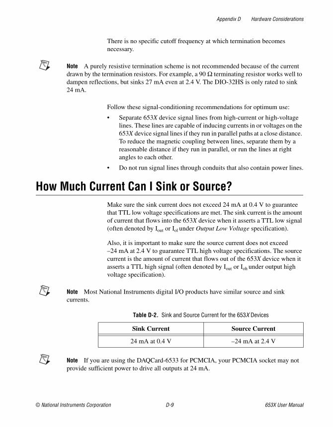
Appendix D Hardware Considerations
© National Instruments Corporation D-9 653X User Manual
There is no specific cutoff frequency at which termination becomes necessary.
Note A purely resistive termination scheme is not recommended because of the current drawn by the termination resistors. For example, a 90 Ω terminating resistor works well to dampen reflections, but sinks 27 mA even at 2.4 V. The DIO-32HS is only rated to sink 24 mA.
Follow these signal-conditioning recommendations for optimum use:
• Separate 653X device signal lines from high-current or high-voltage lines. These lines are capable of inducing currents in or voltages on the 653X device signal lines if they run in parallel paths at a close distance. To reduce the magnetic coupling between lines, separate them by a reasonable distance if they run in parallel, or run the lines at right angles to each other.
• Do not run signal lines through conduits that also contain power lines.
How Much Current Can I Sink or Source?Make sure the sink current does not exceed 24 mA at 0.4 V to guarantee that TTL low voltage specifications are met. The sink current is the amount of current that flows into the 653X device when it asserts a TTL low signal (often denoted by Iout or Iol under Output Low Voltage specification).
Also, it is important to make sure the source current does not exceed –24 mA at 2.4 V to guarantee TTL high voltage specifications. The source current is the amount of current that flows out of the 653X device when it asserts a TTL high signal (often denoted by Iout or Ioh under output high voltage specification).
Note Most National Instruments digital I/O products have similar source and sink currents.
Note If you are using the DAQCard-6533 for PCMCIA, your PCMCIA socket may not provide sufficient power to drive all outputs at 24 mA.
Table D-2. Sink and Source Current for the 653X Devices
Sink Current Source Current
24 mA at 0.4 V –24 mA at 2.4 V

Appendix D Hardware Considerations
653X User Manual D-10 ni.com
RTSI and PXI Trigger Bus InterfacesYou can use the seven bidirectional RTSI lines on the RTSI bus to share signals between devices. Use the RTSI bus interface to synchronize multiple cards or change control signals with multiple devices.
The PCI-6534, PCI-DIO-32HS and AT-DIO-32HS each contain a RTSI connector and an interface to the National Instruments RTSI bus. The RTSI bus provides seven trigger lines and a system clock line. All National Instruments AT- and PCI-bus devices that have RTSI bus connectors can be cabled together inside a computer to share these signals.
The PXI-653X uses pins on the PXI J2 connector to connect the RTSI bus to the PXI trigger bus as defined in the PXI Specification, rev. 1.0. All National Instruments PXI modules that provide a connection to these pins can be connected together by software. This feature is available only when the PXI-653X is used in a PXI-compatible chassis. It is not supported in CompactPCI chassis.
Board, RTSI, and PXI Bus ClocksThe 653X device requires a clock to run the handshaking logic and to generate sampling intervals for pattern I/O. The frequency timebase must be 20 MHz.
The 653X device can use its internal 20 MHz clock source, or you can provide a clock from another 20 MHz device over the RTSI bus. When using its internal 20 MHz clock, the 653X device can also drive its internal timebase onto the bus and to another device that uses a 20 MHz clock.
Whether internal or external, the 20 MHz clock serves as the primary frequency source for the 653X device. By default, the 653X device uses an internal clock. You can programmatically change the source of the clock through software.
♦ PXI-6533—The PXI-6533 uses PXI trigger line 7 as the RTSI clock line.

Appendix D Hardware Considerations
© National Instruments Corporation D-11 653X User Manual
RTSI and PXI Bus TriggersThe seven RTSI lines on the RTSI bus provide a very flexible interconnection scheme for any device sharing the RTSI or PXI-trigger bus. Any control signal on the device can connect to a RTSI or PXI-trigger bus line. You can drive output control signals onto the bus and receive input control signals from the bus. Figure D-6 shows the signal connection scheme.
Note If you configure a signal to be received from the RTSI bus, do not attach it to an external source. Also, do not configure the 653X device to generate that signal internally.
Figure D-6. RTSI Bus Signal Connection
RT
SI B
us o
r P
XI C
onne
ctor
Cro
ssba
r S
witc
hTrigger
20 MHz Timebase
REQ<1..2>
ACK<1..2>(STARTTRIG<1..2>)
PCLK<1..2>
DAQ-DIO
STOPTRIG<1..2>
Switch
7
2
2
2
2

© National Instruments Corporation E-1 653X User Manual
EOptimizing Your Transfer Rates
Use this appendix to determine the maximum transfer rate for your device, optimize transfer rates, and to see example benchmark results.
Determining the Maximum Transfer RatesThe maximum sustainable transfer rate a 653X device can achieve depends on the minimum available bus bandwidth and is based on your computer system. The maximum sustainable transfer rate also depends on the number of other devices generating bus cycles, your operating system, and your application software. The maximum sustainable transfer rate is always lower than the peak transfer rate.
The average bus bandwidth from highest to lowest is in the following order:
• PCI/PXI-6534
• PCI/PXI-6533
• AT-DIO-32HS
• DAQCard-6533 for PCMCIA
With the 6534 devices, if the data you are acquiring/generating fits in the onboard memory, the transfer rate is not limited by the bus bandwidth, only by the maximum transfer rate based on the protocol used. These rates are listed in Table E-1. The peak transfer rates are based on using a 1 meter cable.
Table E-1. Peak Transfer Rates Based on Mode and Protocol Used
Mode/Protocol Peak Rate (MS/s)
Handshaking 8255 5
Handshaking Level-ACK 3.33
Handshaking Leading-Edge Pulse 3.33
Handshaking Long Pulse 3.33

Appendix E Optimizing Your Transfer Rates
653X User Manual E-2 ni.com
Obtaining the Fastest Transfer RatesTo achieve the highest transfer rates possible, consider the following:
• Burst mode is the fastest handshaking protocol. You can further increase speed by using short cables.
• Minimize the number of other I/O devices active in the system. Your system bus should be as free as possible from unrelated activity.
• Use the 6534 devices, which have onboard memory. If you are using a 6533 device, you can connect it to an external FIFO using the burst handshaking protocol and clock data out of the FIFO to the peripheral device.
• Direct-memory access (DMA) transfers are faster than interrupt-driven transfers, especially for pattern I/O. Refer to Table E-2 to determine whether your device supports DMA transfers. If DMA transfers are available, the software will use it by default.
Handshaking Trailing-Edge Pulse 1.8
Handshaking Burst 20
Pattern I/O 20
Table E-2. Devices That Support Direct-Memory Access (DMA) Transfers
Device Direct-Memory Access
AT-DIO-32HS Supported if system DMA resources available. If you are using two DMA channels, data transfer is faster.
DAQCard-6533 for PCMCIA
Not supported
PCI-DIO-32HSPCI-6534
Supported
PXI-6533PXI-6534
Supported if device is in a peripheral slot that allows bus arbitration (bus mastering). Otherwise, use software to select interrupt-driven transfers. PXI chassis have bus arbitration for all slots.
Table E-1. Peak Transfer Rates Based on Mode and Protocol Used (Continued)
Mode/Protocol Peak Rate (MS/s)

Appendix E Optimizing Your Transfer Rates
© National Instruments Corporation E-3 653X User Manual
Interpreting Benchmark ResultsUse benchmark results to get a general idea of what transfer rates to expect for an application. Since these results are system dependent, they are not to be used as specifications. View latest results on our website, ni.com
Benchmark results are in megasamples per second and sample size is user defined. For example, if you are performing an eight-bit operation, then sample size is one byte. Sixteen bits is two bytes and 32 bits is four bytes.
To convert from MS/s to MB/s, use the following formula:
where sample size can be one, two, or four bytes.
For example, 10 MS/s, where each sample is 16 bits or two bytes:
The following applications were tested:
• Single Shot (pattern I/O and burst protocol)—One buffer of data is transferred one time.
• Continuous Retransmit Output (pattern I/O and burst protocol)—One buffer of data is loaded into memory one time, and outputted over and over again.
• Continuous Input (pattern I/O and burst protocol)—New data is continually inputted into the application software.
MSs
--------sample size (B)
1S-------------------------------------× MB
s--------=
10MSs
--------------2 bytes
1S----------------× 20MB
s---------------=

Appendix E Optimizing Your Transfer Rates
653X User Manual E-4 ni.com
AT-DIO-32HSThe following benchmarks are results using a Dell Dimension XPS, 600 MHz, PIII, and Windows 98 SE.
PCI-DIO-32HSThe following benchmarks are results using a Gateway 550 MHz PIII, 128 MB RAM, and Windows 98 SE.
Table E-3. AT-DIO-32HS Benchmark Results
Mode
Benchmark Rate(MS/s)
8 Bit 16 Bit 32 Bit
Pattern I/O–Single Shot
Input 1.67 .87 .83
Output 1.47 .74 .38
Pattern I/O–Continuous
Input 1.67 .80 .31
Pattern I/O–Continuous Retransmit
Output 1.43 .67 .39
Burst Protocol–Continuous
Input 1.74 .87 .43
Burst Protocol–Continuous Retransmit
Output 1.51 .76 .37
Table E-4. PCI-DIO-32HS Benchmark Results
Mode
Benchmark Rate(MS/s)
8 Bit 16 Bit 32 Bit
Pattern I/O–Single Shot
Input 10 5 5
Output 4 2.2 1.81
Pattern I/O–Continuous
Input 10 5 3.33

Appendix E Optimizing Your Transfer Rates
© National Instruments Corporation E-5 653X User Manual
PXI-6533The following benchmarks are results using a PXI-8170, 450 MHz PIII, and Windows 98.
Pattern I/O–Continuous Retransmit
Output 4 1.81 1.81
Burst Protocol–Continuous
Input 19.93 19.6 19.05
Burst Protocol–Continuous Retransmit
Output 19.92 19.58 18.54
Table E-5. PXI-6533 Benchmark Results
Mode
Benchmark Rate(MS/s)
8 Bit 16 Bit 32 Bit
Pattern I/O–Single Shot
Input 10 6.67 5
Output 5 2.5 2.5
Pattern I/O–Continuous
Input 10 5 3.33
Pattern I/O–Continuous Retransmit
Output 4 2.5 2.22
Burst Protocol–Continuous
Input 19.94 19.63 19.47
Burst Protocol–Continuous Retransmit
Output 19.75 18.09 9.15
Table E-4. PCI-DIO-32HS Benchmark Results (Continued)
Mode
Benchmark Rate(MS/s)
8 Bit 16 Bit 32 Bit

Appendix E Optimizing Your Transfer Rates
653X User Manual E-6 ni.com
DAQCard-6533 for PCMCIAThe following benchmarks are results using a PXI-8170, 450 MHz PIII, and Windows 98.
PCI-6534The following benchmarks are results using a Dell Dimension XPS T600r, 600 MHz PIII, 128 MB RAM, and Windows 98 SE.
Table E-6. DAQCard-6533 for PCMCIA Benchmark Results
Mode
Benchmark Rate(MS/s)
8 Bit 16 Bit 32 Bit
Pattern I/O–Single Shot
Input 0.12 .11 .10
Output 0.12 .12 .10
Pattern I/O–Continuous
Input 0.12 .11 .10
Pattern I/O–Continuous Retransmit
Output 0.12 .12 .10
Burst Protocol–Continuous
Input 0.24 .24 .19
Burst Protocol–Continuous Retransmit
Output 0.24 .24 .19
Table E-7. PCI-6534 Benchmark Results
Mode
Benchmark Rate(MS/s)
8 Bit 16 Bit 32 Bit
Pattern I/O–Single Shot*
Input 20 20 20
Output 20 20 20
Pattern I/O–Continuous Retransmit
Output 20 20 20

Appendix E Optimizing Your Transfer Rates
© National Instruments Corporation E-7 653X User Manual
PXI-6534The following benchmarks are results using a PXI-8170, 450 MHz PIII, and Windows 98.
Burst Protocol–Single Shot*
Input 20 20 20
Output 20 20 20
Burst Protocol–Continuous Retransmit**
Output 20 20 20
* Benchmarks made using buffer size ≤ onboard memory.** Benchmarks made using buffer retransmitted ≤ onboard memory.
Table E-8. PXI-6534 Benchmark Results
Mode
Benchmark Rate(MS/s)
8 Bit 16 Bit 32 Bit
Pattern I/O–Single Shot*
Input 20 20 20
Output 20 20 20
Pattern I/O–Continuous Retransmit
Output 20 20 20
Burst Protocol–Single Shot*
Input 20 20 20
Output 20 20 20
Burst Protocol–Continuous Retransmit**
Output 20 20 20
* Benchmarks made using buffer size ≤ onboard memory.** Benchmarks made using buffer retransmitted ≤ onboard memory.
Table E-7. PCI-6534 Benchmark Results (Continued)
Mode
Benchmark Rate(MS/s)
8 Bit 16 Bit 32 Bit

Appendix E Optimizing Your Transfer Rates
653X User Manual E-8 ni.com
PCI-7030/6533 with LabVIEW RTThe following benchmarks are results using a 133 MHz AMD 486DX5 class processor, and the real-time operating system running on LabVIEW RT.
PXI-6533 with LabVIEW RTThe following benchmarks are results using a PXI-8170, 450 MHz PIII, and the real-time operating system running on LabVIEW RT.
Table E-9. PCI-7030/6533 Benchmark Results
Mode
Benchmark Rate(MS/s)
8 Bit 16 Bit 32 Bit
Pattern I/O–Single Shot
Input 1.82 .95 .49
Output 1.82 .91 .47
Pattern I/O–Continuous
Input 1.67 .87 .48
Pattern I/O–Continuous Retransmit
Output 1.25 .65 .48
Burst Protocol–Continuous
Input 2.04 1.02 .49
Output 1.99 .95 .48
Table E-10. PCI-7030/6533 Benchmark Results
Mode
Benchmark Rate(MS/s)
8 Bit 16 Bit 32 Bit
Pattern I/O–Single Shot
Input 10 10 6.67
Output 10 6.67 4
Pattern I/O–Continuous
Input 2.50 1.54 1.43
Output 2 1 1

Appendix E Optimizing Your Transfer Rates
© National Instruments Corporation E-9 653X User Manual
Pattern I/O–Continuous Retransmit
Output 2.50 1.25 1.25
Burst Protocol–Continuous
Input 19.98 19.97 19.97
Output 19.97 17.72 8.60
Table E-10. PCI-7030/6533 Benchmark Results (Continued)
Mode
Benchmark Rate(MS/s)
8 Bit 16 Bit 32 Bit

© National Instruments Corporation F-1 653X User Manual
FTechnical Support Resources
Web SupportNational Instruments Web support is your first stop for help in solving installation, configuration, and application problems and questions. Online problem-solving and diagnostic resources include frequently asked questions, knowledge bases, product-specific troubleshooting wizards, manuals, drivers, software updates, and more. Web support is available through the Technical Support section of ni.com
NI Developer ZoneThe NI Developer Zone at ni.com/zone is the essential resource for building measurement and automation systems. At the NI Developer Zone, you can easily access the latest example programs, system configurators, tutorials, technical news, as well as a community of developers ready to share their own techniques.
Customer EducationNational Instruments provides a number of alternatives to satisfy your training needs, from self-paced tutorials, videos, and interactive CDs to instructor-led hands-on courses at locations around the world. Visit the Customer Education section of ni.com for online course schedules, syllabi, training centers, and class registration.
System IntegrationIf you have time constraints, limited in-house technical resources, or other dilemmas, you may prefer to employ consulting or system integration services. You can rely on the expertise available through our worldwide network of Alliance Program members. To find out more about our Alliance system integration solutions, visit the System Integration section of ni.com

Appendix F Technical Support Resources
653X User Manual F-2 ni.com
Worldwide SupportNational Instruments has offices located around the world to help address your support needs. You can access our branch office Web sites from the Worldwide Offices section of ni.com. Branch office web sites provide up-to-date contact information, support phone numbers, e-mail addresses, and current events.
If you have searched the technical support resources on our Web site and still cannot find the answers you need, contact your local office or National Instruments corporate. Phone numbers for our worldwide offices are listed at the front of this manual.

© National Instruments Corporation G-1 653X User Manual
Glossary
Prefix Meaning Value
k- kilo- 103
µ- micro- 10– 6
m- milli- 10–3
M- mega- 106
n- nano- 10–9
Numbers/Symbols
° degrees
– negative of, or minus
< less than
> greater than
≤ less than or equal to
≥ greater than or equal to
Ω ohms
/ per
% percent
± plus or minus
+ positive of, or plus
+5 V (signal) +5 VDC source signal

Glossary
653X User Manual G-2 ni.com
A
A amps
ACK acknowledge—handshaking signal driven by the 653X device, indicating that it is ready to transfer data
ADE Application Development Environment
API Application Programming Interface—a standardized set of subroutines or functions along with the parameters that a program can call
asynchronous For hardware, it is a property of an event that occurs at an arbitrary time, without synchronization to a reference clock. In software, it is the property of a function that begins an operation and returns prior to the completion or termination of the operation.
B
b bits
B bytes
bidirectional data lines data lines that can be programmatically configured as input or output
buffer temporary storage for acquired or generated data (software)
bus The group of conductors that interconnect individual circuitry in a computer. Typically, a bus is the expansion vehicle to which I/O or other devices are connected.
C
cache high-speed processor memory that buffers commonly used instructions or data to increase processing throughput
clock hardware component that controls timing for reading from or writing to groups
CH channel

Glossary
© National Instruments Corporation G-3 653X User Manual
channel Pin or wire lead to which you apply or from which you read the analog or digital signal. For digital signals, you group channels to form ports. Ports usually consist of either four or eight digital channels.
CompactPCI core specification defined by the PCI Industrial Computer Manufacturer’s Group (PICMG)
compiler A software utility that converts a source program in a high-level programming language, such as LabVIEW, Basic, C or Pascal, into an object or compiled program in machine language. Compiled programs run 10 to 1,000 times faster than interpreted programs. Some languages, such as Java, are compiled to an intermediate language that is interpreted at run time.
control signals Signals that regulate/control the timing of your data transfer in handshaking I/O and pattern I/O. There are four control signals in your 653X device: ACK (STARTTRIG), REQ, STOPTRIG, and PCLK.
counter/timer a circuit that counts external pulses or clock pulses (timing)
CPULL A user-configurable 2.2 kΩ internal resistor for control lines. You can connect the line to +5 VDC (pull up) or connect the line to ground (pull down).
current sinking the ability to dissipate current for analog or digital signals
current sourcing the ability to supply current for analog or digital signals
D
DAQ Data Acquisition—Collecting and measuring electrical signals from sensors, transducers, and test probes or fixtures and inputting them to a computer for processing. Also refers to collecting and measuring the same kinds of electrical signals with analog-to-digital and/or digital devices plugged into a PC, and possibly generating control signals with digital-to-analog and/or digital devices in the same PC.
Data In Valid data generated by peripheral device that is ready for input to the 653X device
DC direct current

Glossary
653X User Manual G-4 ni.com
default setting A default parameter value recorded in the driver. In many cases, the default input of a control is a certain value (often 0) that means use the current default setting.
device A plug-in data acquisition board, card, or pad that can contain multiple channels and conversion devices. Plug-in boards, PCMCIA cards, and devices that connects to your computer parallel port, are all examples of DAQ devices.
DGND digital ground
digital trigger a TTL-level signal having two discrete levels—a high and a low level
DIO Digital Input/Output
DMA Direct Memory Access—a method by which data can be transferred to or from computer memory from or to a device or memory on the bus while the processor does something else. DMA is the fastest method of transferring data to or from computer memory.
DPULL A user-configurable 100 kΩ internal resistor for data lines. You can connect the line to +5 VDC (pull up) or connect the line to ground (pull down).
F
FIFO First-In First-Out memory buffer—the first data stored is the first data sent to the acceptor. FIFOs are often used on DAQ devices to temporarily store incoming or outgoing data until that data can be retrieved or output. For example, an analog input FIFO stores the results of A/D conversions until the data can be retrieved into system memory, a process that requires the servicing of interrupts and often the programming of the DMA controller. This process can take several milliseconds in some cases. During this time, data accumulates in the FIFO for future retrieval. With a larger FIFO, longer latencies can be tolerated. In the case of analog output, a FIFO permits faster update rates, because the waveform data can be stored on the FIFO ahead of time. This again reduces the effect of latencies associated with getting the data from system memory to the DAQ device.
function a set of software instructions executed by a single line of code that may have input and/or output parameters and returns a value when executed

Glossary
© National Instruments Corporation G-5 653X User Manual
G
group A collection of one, two, or four ports and an associated timing controller. All buffered operations must be performed on groups.
H
handshaking I/O Data-transfer mode in which the 653X device engages in a two-way communication with the peripheral device. The 653X asserts a signal, ACK, when it is ready for a data transfer and the peripheral device asserts a separate signal, REQ, when it is ready for a data transfer. Data is transferred only when both the 653X and the peripheral device are ready.
I
interrupt a computer signal indicating that the CPU should suspend its current task to service a designated activity
I/O Input/Output—a transfer of data to/from a computer system involving communications channels, operator interface devices, and/or data acquisition and control interfaces
K
k Kilo—the standard metric prefix for 1,000, or 103, used with units of measure such as volts, hertz, and meters
L
line Individual digital bit
LSB Least significant bit
low/high Refers to the active, or “on” state of handshaking I/O lines. For example, if ACK is active low, the 653X device is ready when its ACK line asserts (changes to) low.

Glossary
653X User Manual G-6 ni.com
M
M Mega—the standard metric prefix for 1 million or 106, when used with units of measure such as volts and hertz
Measurement & Automation Explorer (MAX)
a controlled centralized configuration environment that allows you to configure all of your National Instruments DAQ, GPIB, IMAQ, IVI, Motion, VISA, and VXI devices
MB/s A unit for data transfer that means one million or 106 bits per second
mask the bits that are significant for pattern detection, also applies to change detection
MSB Most Significant Bit
P
pattern I/O Data-transfer mode in which 653X transfers data on the falling or rising edge of a TTL signal, typically at a constant rate
PCI Peripheral Component Interconnect—A high-performance expansion bus architecture originally developed by Intel to replace ISA and EISA. It has achieved widespread acceptance as a standard for PCs and workstations; it offers a theoretical maximum transfer rate of 132 MB/s.
PCLK see control signals
PCMCIA An expansion bus architecture that has found widespread acceptance as a de facto standard in notebook-sized computers. It originated as a specification for add-on memory cards written by the Personal Computer Memory Card International Association.
peripheral device any external device connected to the 653X device that the 653X controls, monitors, tests, or communicates with
Plug and Play ISA a specification prepared by Micorsoft, Intel, and other PC-related companies that will result in PCs with plug-in boards that can be fully configured in software, without jumpers or switches on the devices
port a collection of lines, usually eight
posttrigger acquiring data that occurs after a trigger

Glossary
© National Instruments Corporation G-7 653X User Manual
pretrigger acquiring data that occurs before a trigger
propagation delay the amount of time required for a signal to pass through a circuit
protocol the exact sequence of bits, characters and control codes used to transfer data between computers and peripherals through a communications channel, such as the GPIB
PXI PCI eXtensions for Instrumentation—a rugged, open system for modular instrumentation based on CompactPCI, with special mechanical, electrical, and software features
R
real time a property of an event or system in which data is processed as it is acquired instead of being accumulated and processed at a later time
REQ Request—Handshaking signal generated by the peripheral device, indicating it is ready. In some transfer modes, the 653X device can internally generate a REQ signal. The REQ signal with a bar above the name indicates it is an inverted request signal.
RGND reserved ground
RT Series DAQ Device A collection of one, two, or four ports and an associated timing controller. All handshaking I/O, pattern I/O and buffered operations must be performed on groups.
RTSI bus Real-Time System Integration Bus—the National Instruments timing bus that connects DAQ devices directly, by means of connectors on top of the devices, for precise synchronization of functions
S
s seconds
S samples
S/s Samples per second—used to express the rate at which a DAQ device samples an analog signal
sample an instantaneous measurement of a signal, normally using an analog-to-digital convertor in a DAQ device

Glossary
653X User Manual G-8 ni.com
sample rate the number of samples a system takes over a given time period, usually expressed in samples per second
software trigger a programmed event that triggers an event such as data acquisition
STOPTRIG see control signals
Strobed I/O Any operation where every data transfer is timed by hardware signals. In the case of pattern I/O, this hardware signal is a clock edge. In the case of handshaking I/O, hardware signals involve two or three handshaking lines.
synchronous For hardware, it is a property of an event that is synchronized to a reference clock. For software, it is a property of a function that begins an operation and returns only when the operation is complete.
T
transfer rate the rate, measured in bytes/s, at which data is moved from source to destination after software initialization and set up operations; the maximum rate at which the hardware can operate
trigger any event that causes or starts some form of data capture
TTL Transistor-Transistor Logic
U
unstrobed I/O Basic digital I/O operations that do not involve the use of control signals in data transfers. Unstrobed data transfers are controlled by software commands. Also known as software-timed I/O.
V
V Volts
VI Virtual Instrument—(1) a combination of hardware and/or software elements, typically used with a PC, that has the functionality of a classic stand-alone instrument (2) a LabVIEW software module (VI), which consists of a front panel user interface and a block diagram program
virtual channels channel names that can be defined outside the application and used without having to perform scaling operations

Glossary
© National Instruments Corporation G-9 653X User Manual
W
wired-OR output driver that drives its output pin to 0 V for logic low, but tri-states the pin (puts the pin in the high-impedance state) for logic high
© National Instruments Corporation I-1 653X User Manual
Index
Numbers+5 V signal, description (table), C-5653X devices. See also hardware; specific
device name.configuring, 1-8 to 1-9installing, 1-6 to 1-8overview, 1-1 to 1-2requirements for getting started, 1-2software programming choices, 1-3 to 1-5
National Instruments application software, 1-3 to 1-4
NI-DAQ driver software, 1-4 to 1-5unpacking, 1-5 to 1-6
8255-emulation handshaking protocol, 3-12 to 3-17
comparison of protocols (table), 3-4 to 3-5input handshaking sequence
(figure), 3-12 to 3-17input state machine (figure), 3-14maximum transfer rate (table), E-2output handshaking sequence (figure), 3-15output state machine (figure), 3-16output timing diagram (figure), 3-17
AACK protocol. See level-ACK handshaking
protocol.ACK<1..2> signal
8255-emulation protocolinput handshaking sequence
(figure), 3-13input state machine (figure), 3-14output handshaking sequence
(figure), 3-15output state machine (figure), 3-16
output timing diagram (figure), 3-17overview, 3-12 to 3-13
burst input timing diagramsdefault input timing diagram
(figure), 3-8PCLK reversed (figure), 3-10transfer example (figure), 3-6
burst output timing diagramsoutput timing diagram (figure), 3-9PCLK reversed (figure), 3-11transfer example (figure), 3-6
connecting signalschange detection, 2-31handshaking I/O, 2-10 to 2-11pattern I/O, 2-24
description (table), C-4handshaking I/O and pattern I/O (table), C-1leading-edge protocol
input handshaking sequence (figure), 3-29
input state machine (figure), 3-30input timing diagram (figure), 3-31output handshaking sequence
(figure), 3-32output state machine (figure), 3-33output timing diagram (figure), 3-34
level-ACK protocolinput handshaking sequence
(figure), 3-18input state machine (figure), 3-19input timing diagram (figure), 3-20output handshaking sequence
(figure), 3-21output state machine (figure), 3-22output timing diagram (figure), 3-23

Index
653X User Manual I-2 ni.com
long-pulse protocolinput handshaking sequence
(figure), 3-35input state machine (figure), 3-36input timing diagram (figure), 3-37output handshaking sequence
(figure), 3-38output state machine (figure), 3-39output timing diagram (figure), 3-40
polarity for handshaking I/Ocomparison of handshaking protocols
(table), 3-4 to 3-5controlling line polarity, 2-8selecting polarity, 2-8
start and stop triggerchange detection, 2-28 to 2-29pattern I/O, 2-20
start triggerchange detection, 2-28pattern I/O, 2-19
trailing-edge protocolinput handshaking sequence
(figure), 3-25input state machine (figure), 3-25input timing diagram (figure), 3-26output handshaking sequence
(figure), 3-27output state machine (figure), 3-27output timing diagram (figure), 3-28
applications, choosing correct mode for (table), 2-1
asynchronous handshaking protocol, 3-12AT-DIO-32HS
benchmark results (table), E-4block diagram, D-1installation, 1-7 to 1-8support for DMA transfers (table), E-2
Bbenchmark results. See optimizing transfer
rates.block diagrams
AT-DIO-32HS, D-1DAQCard-6533 for PCMCIA, D-2PCI-DIO-32HS, PCI/PXI-7030/6533, and
PXI-6533, D-3PCI/PXI-6534, D-4
burst handshaking protocolcomparison of protocols (table),
3-4 to 3-5input timing diagrams, 3-5 to 3-11
default timing diagram (figure), 3-8PCLK reversed (figure), 3-10transfer example (figure), 3-6
maximum transfer rate (table), E-3output timing diagrams, 3-5 to 3-11
default timing diagram (figure), 3-9PCLK reversed (figure), 3-11transfer example (figure), 3-6
overview, 2-7, 3-5PCLK signal direction, 2-7 to 2-8
bus interfacesRTSI and PXI trigger bus interfaces,
D-10 to D-11specifications, A-3
Ccable selection and termination, D-6 to D-9
Schottky-diode termination scheme, D-7 to D-9
transmission line terminations (figure), D-8
change detection, 2-26 to 2-33connecting signals, 2-31continuous or finite data transfer,
2-30 to 2-31continuous input, 2-30

Index
© National Instruments Corporation I-3 653X User Manual
DMA or interrupt transfers, 2-31finite, 2-30
overview, 2-26port and timing controller combinations
(table), 2-26 to 2-27programming, 2-31 to 2-33
continuous change detection in NI-DAQ (figure), 2-32
LabVIEW/LabVIEW RT (figure), 2-33
single buffer change detection in NI-DAQ (figure), 2-32
specifications, A-3specifying lines to monitor, 2-27triggering data transfer, 2-27 to 2-30
pattern-matching trigger, 2-29 to 2-30
start and stop trigger, 2-28 to 2-29start trigger, 2-28stop trigger, 2-28
when to use (table), 2-1width of data to acquire, 2-26
clocks, for RTSI and PXI trigger bus interfaces, D-10
CompactPCI, using with PXI, B-1configuration, 653X devices
Mac OS, 1-9Windows, 1-8 to 1-9
connecting signals. See signal connections.continuous or finite data transfer
change detection, 2-30 to 2-31continuous input, 2-30DMA or interrupt transfers, 2-31finite, 2-30
handshaking I/O, 2-9 to 2-10continuous input, 2-9continuous output, 2-9 to 2-10DMA or interrupt transfers, 2-10finite, 2-9
pattern I/O, 2-21 to 2-22continuous input, 2-21 to 2-22
continuous output, 2-22DMA or interrupt transfers, 2-22finite, 2-21
control linesGroup1 and Group2 controllers,
1-1 to 1-2handshaking I/O and pattern I/O
(table), C-1using as extra unstrobed data lines,
2-3 to 2-4CPULL signal
description (table), C-5power-on state, D-5
customer education, F-1
DDAQCard-6533 for PCMCIA
benchmark results (table), E-6block diagram, D-2installation, 1-8
data transferchange detection
continuous or finite data transfer, 2-30 to 2-31
triggering data transfer, 2-27 to 2-30width of data to acquire, 2-26 to 2-27
handshaking I/Ocontinuous or finite data
transfer, 2-9 to 2-10direction of data transfer, 2-6width of data to transfer, 2-6
optimizing transfer rates, E-1 to E-9benchmark results, E-3 to E-9maximum transfer rates, E-1 to E-2obtaining fastest transfer rates, E-2
pattern I/Ocontinuous or finite data
transfer, 2-21 to 2-22direction of data transfer, 2-18monitoring data transfer, 2-23

Index
653X User Manual I-4 ni.com
rate of data transfer, 2-18 to 2-19triggering data transfer, 2-19 to 2-21width of data to transfer, 2-17
delay, programmable, handshaking protocol, 2-8 to 2-9
digital I/O specifications, A-1 to A-2digital lines. See static digital lines.digital patterns and waveforms. See pattern
I/O.DIOA<0..7> signal (table), C-4DIOB<0..7> signal (table), C-4DIOC<0..7> signal (table), C-5DIOD<0..7> signal, description (table), C-5DMA or interrupt transfers
change detection, 2-31devices that support DMA transfers
(table), E-2handshaking I/O, 2-10pattern I/O, 2-22
DPULL signaldescription (table), C-5power-on state, D-5
Eedge-based handshaking protocols. See signal
edge-based handshaking protocols.environment specifications, A-4 to A-5equipment, optional, for connecting
signals, C-7
Ffinite data transfer. See continuous or finite
data transfer.
GGND signal, description (table), C-5
Hhandshaking I/O, 2-6 to 2-17. See also
handshaking I/O timing diagrams.ACK/REQ signal polarity, 2-8connecting signals, 2-10 to 2-11continuous or finite data
transfer, 2-9 to 2-10continuous input, 2-9continuous output, 2-9 to 2-10DMA or interrupt transfers, 2-10finite, 2-9
direction of data transfer, 2-6maximum transfer rates (table),
E-1 to E-2port and timing controller combinations
(table), 2-6programmable delay, 2-8 to 2-9programming, 2-12 to 2-17
buffered handshaking I/O in NI-DAQ (figure), 2-13
handshaking input in LabVIEW/LabVIEW RT (figure), 2-15
handshaking output in LabVIEW/LabVIEW RT (figure), 2-16
unbuffered handshaking I/O in NI-DAQ (figure), 2-14
protocolsburst protocol, 2-7 to 2-8deciding on a protocol, 2-7
startup sequence, 2-11 to 2-12controlling line polarities, 2-12initialization order, 2-11 to 2-12
when to use (table), 2-1width of data to transfer, 2-6
handshaking I/O timing diagrams, 3-4 to 3-408255-emulation protocol, 3-12 to 3-17
input handshaking sequence (figure), 3-12 to 3-17
input state machine (figure), 3-14

Index
© National Instruments Corporation I-5 653X User Manual
output handshaking sequence (figure), 3-15
output state machine (figure), 3-16output timing diagram (figure), 3-17
asynchronous protocol, 3-12burst protocol input timing
diagram, 3-5 to 3-11default timing diagram (figure), 3-8PCLK reversed (figure), 3-10transfer example (figure), 3-6
burst protocol output timing diagram, 3-5 to 3-11
default timing diagram (figure), 3-9PCLK reversed (figure), 3-11transfer example (figure), 3-6
comparing different protocols (table), 3-4 to 3-5
leading-edge protocol, 3-29 to 3-34input handshaking sequence
(figure), 3-29input state machine (figure), 3-30input timing diagram (figure), 3-31output handshaking sequence
(figure), 3-32output state machine (figure), 3-33output timing diagram (figure), 3-34
level-ACK protocol, 3-18 to 3-23input handshaking sequence
(figure), 3-18input state machine (figure), 3-19input timing diagram (figure), 3-20output handshaking sequence
(figure), 3-21output state machine (figure), 3-22output timing diagram (figure), 3-23
long-pulse protocol, 3-35 to 3-40input handshaking sequence
(figure), 3-35input state machine (figure), 3-36input timing diagram (figure), 3-37
output handshaking sequence (figure), 3-38
output state machine (figure), 3-39output timing diagram (figure), 3-40
signal edge-based protocols, 3-24trailing-edge protocol, 3-25 to 3-28
input state machine (figure), 3-25input timing diagram (figure), 3-26output state machine (figure), 3-27output timing diagram (figure), 3-28
hardware, D-1 to D-11block diagrams
AT-DIO-32HS, D-1DAQCard-6533 for PCMCIA, D-2PCI-DIO-32HS,
PCI/PXI-7030/6533, and PXI-6533, D-3
PCI/PXI-6534, D-4cable selection and termination,
D-6 to D-9Schottky-diode termination
scheme, D-7 to D-9transmission line terminations
(figure), D-8configuration
Mac OS, 1-9Windows, 1-8 to 1-9
installationAT-DIO-32HS, 1-7 to 1-8DAQCard-6533 for PCMCIA, 1-8PCI-DIO-32HS, PCI-6534, or
PCI-7030/6533 devices, 1-6 to 1-7PXI-6533, PXI-6534, or
PXI-7030/6533 devices, 1-7software, 1-5unpacking 653X devices, 1-5 to 1-6
power connections, D-5 to D-6power-on state, D-5RTSI and PXI trigger bus interfaces,
D-10 to D-11

Index
653X User Manual I-6 ni.com
board, RTSI, and PXI bus clocks, D-10
RTSI and PXI bus triggers, D-11sink and source current, D-9
Iinitialization order, handshaking I/O,
2-11 to 2-12installation
AT-DIO-32HS, 1-7 to 1-8DAQCard-6533 for PCMCIA, 1-8PCI-DIO-32HS, PCI-6534, or
PCI-7030/6533 devices, 1-6 to 1-7PXI-6533, PXI-6534, or PXI-7030/6533
devices, 1-7software, 1-5unpacking 653X devices, 1-5 to 1-6
interrupt transfers. See DMA or interrupt transfers.
LLabVIEW and LabVIEW RT software, 1-3leading-edge handshaking protocol,
3-29 to 3-34comparison of protocols
(table), 3-4 to 3-5definition, 3-24input handshaking sequence
(figure), 3-29input state machine (figure), 3-30input timing diagram (figure), 3-31maximum transfer rate (table), E-2output handshaking sequence
(figure), 3-32output state machine (figure), 3-33output timing diagram (figure), 3-34
level-ACK handshaking protocol, 3-18 to 3-23
comparison of protocols (table), 3-4 to 3-5
input handshaking sequence (figure), 3-18
input state machine (figure), 3-19input timing diagram (figure), 3-20maximum transfer rate (table), E-2output handshaking sequence
(figure), 3-21output state machine (figure), 3-22output timing diagram (figure), 3-23
line state, monitoring. See change detection.long-pulse handshaking protocol, 3-35 to 3-40
comparison of protocols (table), 3-4 to 3-5
definition, 3-24input handshaking sequence
(figure), 3-35input state machine (figure), 3-36input timing diagram (figure), 3-37maximum transfer rate (table), E-2output handshaking sequence
(figure), 3-38output state machine (figure), 3-39output timing diagram (figure), 3-40
MMeasurement Studio software, 1-3memory specifications, A-2monitoring data transfer, pattern I/O, 2-23monitoring line state. See change detection.
NNational Instruments application
software, 1-3 to 1-4NI Developer Zone, F-1NI-DAQ driver software
compatibility with devices (table), 1-5overview, 1-4 to 1-5

Index
© National Instruments Corporation I-7 653X User Manual
Ooptimizing transfer rates, E-1 to E-9
benchmark results, E-3 to E-9AT-DIO-32HS (table), E-4DAQCard-6533 for PCMCIA
(table), E-6PCI-6534, E-6 to E-7PCI-7030/6533 with LabVIEW RT
(table), E-8PCI-DIO-32HS (table), E-4 to E-5PXI-6533 (table), E-5PXI-6533 with LabVIEW RT (table),
E-8 to E-9PXI-6534 (table), E-7
maximum transfer rates, E-1 to E-2obtaining fastest transfer rates, E-2
optional equipment for connecting signals, C-7
Ppattern I/O, 2-17 to 2-26
connecting signals, 2-23 to 2-24continuous or finite data transfer
continuous input, 2-21 to 2-22continuous output, 2-22DMA or interrupt transfers, 2-22finite, 2-21
internal or external REQ source, 2-18maximum transfer rate (table), E-3monitoring data transfer, 2-23port and timing controller combinations
(table), 2-17programming, 2-24 to 2-26
continuous, in NI-DAQ, 2-25LabVIEW/LabVIEW RT, 2-25single buffer, in NI-DAQ, 2-24
REQ polarity, 2-18specifications, A-3
timing diagrams, 3-1 to 3-3external REQ signal source,
3-2 to 3-3internal REQ signal source,
3-1 to 3-2transfer direction, 2-18transfer rate, 2-18 to 2-19triggering data transfer, 2-19 to 2-21
pattern-matching trigger (input only), 2-20 to 2-21
start and stop trigger, 2-20 to 2-21start trigger, 2-19stop trigger, 2-19 to 2-20
when to use (table), 2-1width of data to transfer, 2-17
pattern-matching triggerchange detection, 2-29 to 2-30input only, pattern I/O, 2-20 to 2-21
PCI-6534 devicebenchmark results (table), E-6 to E-7block diagram, D-4installation, 1-6support for DMA transfers (table), E-2
PCI-7030/6533 devicebenchmark results (table), E-8block diagram, D-3installation, 1-6
PCI-DIO-32HSbenchmark results (table), E-4 to E-5block diagram, D-3installation, 1-6 to 1-7support for DMA transfers (table), E-2
PCLK<1..2> signalburst input timing diagrams
default input timing diagram (figure), 3-8
PCLK reversed (figure), 3-10transfer example (figure), 3-6
burst output timing diagramsoutput timing diagram (figure), 3-9PCLK reversed (figure), 3-11

Index
653X User Manual I-8 ni.com
transfer example (figure), 3-6description (table), C-4frequency selection for programmable
delay, 2-8 to 2-9handshaking I/O and pattern I/O
(table), C-1signal direction for burst
protocol, 2-7 to 2-8physical specifications, A-4pin assignments
50-pin signal connections (figure), C-668-pin signal connections (figure), C-2
polarityACK/REQ signals, 2-8
comparison of handshaking protocols (table), 3-4 to 3-5
controlling line polarities, 2-12Port 4 lines (table), 2-4power connections, D-5 to D-6power specifications
power available at I/O connector, A-4power requirement, A-4
power-on state, D-5programmable delay, handshaking protocol,
2-8 to 2-9programming. See also software programming
choices.change detection, 2-31 to 2-33
continuous change detection in NI-DAQ (figure), 2-32
LabVIEW/LabVIEW RT (figure), 2-33
single buffer change detection in NI-DAQ (figure), 2-32
handshaking I/O, 2-12 to 2-17buffered handshaking I/O in NI-DAQ
(figure), 2-13handshaking input in
LabVIEW/LabVIEW RT (figure), 2-15
handshaking output in LabVIEW/LabVIEW RT (figure), 2-16
unbuffered handshaking I/O in NI-DAQ (figure), 2-14
pattern I/O, 2-24 to 2-26continuous, in NI-DAQ, 2-25LabVIEW/LabVIEW RT, 2-25single buffer, in NI-DAQ, 2-24
unstrobed I/O, 2-4 to 2-6control/timing lines as extra
unstrobed data lines, 2-5 to 2-6flowcharts, 2-5
PXI, using with CompactPCI, B-1PXI bus interface. See RTSI and PXI trigger
bus interfaces.PXI-6533 device
benchmark results (table), E-5with LabVIEW RT, E-8 to E-9installation, 1-7support for DMA transfers (table), E-2
PXI-6534 devicebenchmark results (table), E-7block diagram, D-4installation, 1-7support for DMA transfers (table), E-2
PXI-7030/6533 devicesblock diagram, D-3installation, 1-7
RREQ<1..2> signal
8255-emulation protocolinput handshaking sequence
(figure), 3-13input state machine (figure), 3-14output handshaking sequence
(figure), 3-15output state machine (figure), 3-16

Index
© National Instruments Corporation I-9 653X User Manual
output timing diagram (figure), 3-17overview, 3-12 to 3-13
burst input timing diagramsdefault input timing diagram
(figure), 3-8PCLK reversed (figure), 3-10transfer example (figure), 3-6
burst output timing diagramsoutput timing diagram (figure), 3-9PCLK reversed (figure), 3-11transfer example (figure), 3-6
connecting signalshandshaking I/O, 2-10 to 2-11pattern I/O, 2-23
description (table), C-4handshaking I/O and pattern I/O
(table), C-1leading-edge protocol
input handshaking sequence (figure), 3-29
input state machine (figure), 3-30input timing diagram (figure), 3-31output handshaking sequence
(figure), 3-32output state machine (figure), 3-33output timing diagram (figure), 3-34
level-ACK protocolinput handshaking sequence
(figure), 3-18input state machine (figure), 3-19input timing diagram (figure), 3-20output handshaking sequence
(figure), 3-21output state machine (figure), 3-22output timing diagram (figure), 3-23
long-pulse protocolinput handshaking sequence
(figure), 3-35input state machine (figure), 3-36input timing diagram (figure), 3-37
output handshaking sequence (figure), 3-38
output state machine (figure), 3-39output timing diagram (figure), 3-40
polarity for handshaking I/Ocomparison of handshaking protocols
(table), 3-4 to 3-5controlling line polarity, 2-12selecting polarity, 2-8
polarity for pattern I/O, 2-18signal source for pattern I/O
choosing internal or external source, 2-18
external REQ signal source, 3-2 to 3-3
internal REQ signal source, 3-1 to 3-2
trailing-edge protocolinput handshaking sequence
(figure), 3-25input state machine (figure), 3-25input timing diagram (figure), 3-26output handshaking sequence
(figure), 3-27output state machine (figure), 3-27output timing diagram (figure), 3-28
requirements for getting started, 1-2RGND signal (table), C-5RTSI and PXI trigger bus interfaces,
D-10 to D-11board, RTSI, and PXI bus clocks, D-10RTSI and PXI bus triggers, D-11RTSI trigger specifications, A-3
SSchottky-diode termination
scheme, D-7 to D-9signal connections, C-1 to C-7
50-pin signal connections, C-6 to C-7accessories (table), C-7

Index
653X User Manual I-10 ni.com
pin assignments (figure), C-668-pin signal connections, C-2 to C-3
accessories (table), C-3pin assignments (figure), C-2
change detection, 2-31control signals (table), C-1handshaking I/O, 2-10 to 2-11optional equipment, C-7pattern I/O, 2-23 to 2-24signal descriptions (table), C-3 to C-5static digital lines, 2-4
signal edge-based handshaking protocolscomparison of protocols
(table), 3-4 to 3-5leading-edge handshaking
protocol, 3-29 to 3-34long-pulse handshaking
protocol, 3-35 to 3-40trailing-edge handshaking
protocol, 3-25 to 3-28types of protocols, 3-24
sink current, D-9software installation, 1-5software programming choices, 1-3 to 1-5
National Instruments application software, 1-3 to 1-4
NI-DAQ driver software, 1-4 to 1-5source current, D-9specifications
bus interfaces, A-3change detection, A-3digital I/O, A-1 to A-2environment, A-4 to A-5memory, A-2pattern I/O, A-3physical, A-4power available at I/O connector, A-4power requirement, A-4triggers
RTSI triggers (PCI, PXI, AT), A-3start and stop triggers, A-3
standard output, unstrobed I/O, 2-2start and stop trigger
change detection, 2-28 to 2-29pattern I/O, 2-20 to 2-21trigger specifications, A-3
start triggerchange detection, 2-28pattern I/O, 2-19
STARTTRIG<1..2> signal (table), C-1startup sequence for handshaking I/O,
2-11 to 2-12controlling line polarities, 2-12initialization order, 2-11 to 2-12
static digital linesconfiguring, 2-2 to 2-3
standard output, 2-2wired-OR output, 2-2 to 2-3
connecting signals, 2-4controlling and monitoring, 2-2 to 2-6Port 4 lines (table), 2-4programming unstrobed I/O, 2-4 to 2-6
control/timing lines as extra unstrobed data lines, 2-5 to 2-6
flowcharts, 2-5using control lines as extra unstrobed data
lines, 2-3 to 2-4stop trigger. See also start and stop trigger.
change detection, 2-28pattern I/O, 2-19 to 2-20
STOPTRIG<1..2> signalconnecting signals
change detection, 2-31pattern I/O, 2-24
description (table), C-4handshaking I/O and pattern I/O
(table), C-1start and stop trigger
change detection, 2-28 to 2-29pattern I/O, 2-20

Index
© National Instruments Corporation I-11 653X User Manual
stop triggerchange detection, 2-28pattern I/O, 2-19 to 2-20
system integration, by National Instruments, F-1
Ttechnical support resources, F-1 to F-2terminating cables. See cable selection and
termination.timing diagrams, 3-1 to 3-40
handshaking I/O, 3-4 to 3-408255-emulation protocol,
3-12 to 3-17asynchronous protocol, 3-12burst protocol, 3-5 to 3-11comparing different protocols
(table), 3-4 to 3-5edge-based protocols, 3-24leading-edge protocol, 3-29 to 3-34level-ACK protocol, 3-18 to 3-23long-pulse protocol, 3-35 to 3-40trailing-edge protocol, 3-25 to 3-28
pattern I/O, 3-1 to 3-3external REQ signal source,
3-2 to 3-3internal REQ signal source,
3-1 to 3-2trailing-edge handshaking
protocol, 3-25 to 3-28comparison of protocols
(table), 3-4 to 3-5definition, 3-24input state machine (figure), 3-25input timing diagram (figure), 3-26maximum transfer rate (table), E-3output state machine (figure), 3-27output timing diagram (figure), 3-28
transferring data. See data transfer.
trigger bus interfaces. See RTSI and PXI trigger bus interfaces.
trigger specificationsRTSI triggers (PCI, PXI, AT), A-3start and stop triggers, A-3
triggering data transferchange detection, 2-27 to 2-30
pattern-matching trigger, 2-29 to 2-30
start and stop trigger, 2-28 to 2-29start trigger, 2-28stop trigger, 2-28
pattern I/O, 2-19 to 2-21pattern-matching trigger (input only),
2-20 to 2-21start and stop trigger, 2-20 to 2-21start trigger, 2-19stop trigger, 2-19 to 2-20
Uunpacking 653X devices, 1-5 to 1-6unstrobed I/O, 2-2 to 2-6
configuring digital lines, 2-2 to 2-3standard output, 2-2wired-OR output, 2-2 to 2-3
Port 4 lines (table), 2-4programming, 2-4 to 2-6
control/timing lines as extra unstrobed data lines, 2-5 to 2-6
flowcharts, 2-5using control lines as extra unstrobed data
lines, 2-3 to 2-4when to use (table), 2-1
VVirtualBench software, 1-3

Index
653X User Manual I-12 ni.com
Wwaveforms. See pattern I/O.Web support from National Instruments, F-1wired-OR output, unstrobed I/O, 2-2 to 2-3Worldwide technical support, F-2