darcy's law and the field equations
TRANSCRIPT
DARCY'S LAW and the FIELD EQUATIONS of the FLOW of UNDERGROUND FLUIDS
A B S T R A C T
M KING HUBBERT MEMBER AlME
In 1856 Henry Darcy described in an appendix to his book, Les Fontaines Publiques de la Ville de Dijon, a series of experiments on the downward flow of water through filter sands, whereby it was established that the rate of flow is given by the equation:
SHELL DEVELOPMENT CO. HOUSTON, TEXAS
in which q is the volume of water cros~ing unit area in unit time, I is the ~hickness of the sand, h, and h, the heights above a reference level o f the water in manometers terminated above and below the sand, re- spectively, and K a factor of proportionality.
This relationship, appropriately, soon became known as Darcy's law. Subsequently many separate attempts have been made to give Darcy's empirical expression a more general physical fornzulation, with the resuit that .so many mutually inconsistent expressions of what is purported to he Darcy's law have appeared in pub- lished literature that sight has often been lost of Darcy's own work and of its significance.
In the present paper, therefore, it shall be our pur- pose to reinform ourselves upon what Darcy himself did, and then to determine the meaning of his results when expressed e.rplicitly in terms of the pertinent physical variables involved. This will be done first by the empirical method used by Darcy himself, and then
Manuscript received in Petroleum Branch office on Sept. 12, 1956. Paper prepared for presentation before Darcy Centennial Hydrology Symposium of the International Association of Hydrology held in Dijon, France. Sept. 20-26, 1956. and for dual publication as part of the Dijon Symposium and in the Darcy Centennial Issue of JourmL2 of Petroleum Technology.
Discmaion of this paper is invited. Discussion in writing ( 3 copies) may be sent to the office of the Journal of Petrolmbm Technology. Any discussion offered after Dec. 31. 1966, should be in the form of a new paper.
by direct derivation from the Navier-Stokes equation of motion of viscous fluids. W e find in this manner that:
q = ( N 4 ( p / p ) [ g - ( l / p ) grad P I = WE, is a physical expression for Darcy's law, which is valid for liquids generally, and for gases at pressures higher than about 20 atmospheres. Here N is a shape factor and d a characteristic length of the pore structure of the solid, p and IL are the density and viscosity of the fluid, a = ( N d 2 ) (pip) is the volume conductivity o f the system, and E = [g - ( l / p ) grad p] is the impell- ing force per unit mass acting upon the fluid. It is found also that Darcy's law is valid only for flow velocities such that the inertial forces are negligible as compared with those arising from viscosity.
In general, three-dimensional space there exist two .superposed physical fields: a field of force of charucter- istic vector E, and a field of flow of vector q. The force field is more general than the flow field since it has values in all space capable of being occupied by the fluid.
So long as the fluid density is constant or is a func- tion of the pressure only,
curl E = 0, E = - grad where
The field of fiow, independently of the force field, must satisfy the conservation of mom, leading to the equation of continuity
div pq = - f ap/at ,
where f is the porosity, und t is the time. For steady rnotion ap/at = 0. and
P E T R O L E U M T R A N S A C T I O N S , A I M E

1) the fluid is also of constant density, div q = 0 .
The two fields are linked together by Darcy's law,
which is physically analogous to Ohm's law in elec- tricity.
Then, when E = - grad @,
q == - u grad @ . By means of the foregoing equations the flow o f both
homogeneous and heterageneous fluids through porous solids becomes amenable to the same kind of analytical treatment as is already familiar in electrical and ther- mal conduction.
The relation of Darcy's work to the development o f a valid theory of the flow of fluids through porous solids is somewhat analogous to that of Faraday to the Maxwellian equations of electromagnetism. It forms a solid experimental foundation for such a field theory, and the errors attributed by various recent authors to Darcy appear upon closer inspection to have been those committed by the authors themselves.
I N T R O D U C T I O N
In Paris in the year 1856 there was published by Victor Dalmont as a part of the Libraire des Corps lmptriaux des Ponts et Chausse'es et des Mines a mono- graph by the French engineer Henry Darcy,' Inspector General of Bridges and Roads, bearing the title:
"LES FONTAINES PUBLIQUES DE LA VILLE DE DIJON
Exposition et Application DES PRINCIPES A SUIVRE ET DES
FORMULES A EMPLOYER Dans les Questions
de DISTRIBUTION D'EAU
Ouvrage Termini5 Par un Appendice Relatif aux Fournitures
d'Eau de Plusieurs Villes AU FILTRAGE DES EAUX
et A la Fabrication des Tuyaux de Fonte,
de Plomb, de Tole et de Bitume."
For several years previously M. Henry Darcy had been engaged in modernizing and enlarging the pub- lic water works of the town of Dijon, and this treatise, comprising a 647-page volume of text and an accom- panying Atlar of illustrations, constitutes an engineer- ing report on that enterprise.
The item of present interest represents only a detail of the general work and appears in an appendix on pages 590 to 594 under the heading "Determination of the Law of Flow of Water Through Sand," and per- tains to a problem encountered by Darcy in designing a suitable filter for the system. Darcy needed to know how large a filter would be required for a given quan- tity of water per day and, unable to find the desired information in the published literature, he proceeded to obtain it experimentally.
A drawing of the apparatus used is given as Fig. 3 in the Atlas and is here reproduced in facsimile as Fig.
Appareil des~rni a ditcrninrr la lo1
de I'iroulernent den I'cau I i travcrs le sable
FIG. FACSIMILE OF DARCY'S ILLUSTRATION OF HIS EXPERIMENTAL APPARATUS. (FROM Les Fontaines Pub-
liques de la Ville de Dijon, Atlas, FIG. 3) .
1. This consisted of a vertical iron pipe, 0.35 m in diameter and 3.50 m in length (the figure shows 3.50 m but the text says 2.50), flanged at both ends. At a height of 0.20 m above the base of the column, there was placed a horizontal screen supported by an iron grillwork upon which rested a column, a meter or so in length, of loose sand. Water could be admitted into the system by means of a pipe, tapped into the column near its top, from the building water supply, and could be discharged through a faucet from the open charn- ber near its bottom. The faucet discharged into a meas- uring tank 1 m square and 0.50 m deep, and the flow rate could be controlled by means of adjustable valves in both the inlet pipe and the outlet faucet.
For measuring the pressures mercury manometers were used, one tapped into each of the open chambers above and below the sand column. The unit of pres- sure employed was the meter o f water and all man- ometer readings were reported in meters of water meas- ured above the bottom of the sand which was taken as an elevation datum. The observations of the mercury manometers were accordingly expressed directly in terms of the heights of the water columns of equivalent water manometers above a standard datum.
The experiments comprised several series of obser- vations made between Oct. 29 and Nov. 2, 1855, and some additional experiments made during Feb. 17 to 18, 1856. For each series the system was charged with
'References glven a t end of paper.
V O L . 2 0 7 . 1956
a different sand and completely filled with water.
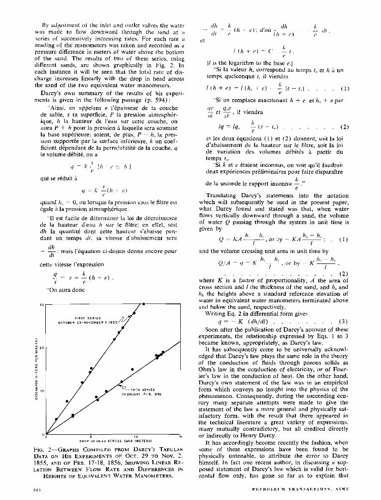
By adjustment of the inlet and o~ltlet valves the water. was made to flow downward through the sand at ;I
series of successively increasing rates. For each rate a reading of the manometers was taken and recorded as a pressure difference in meters of water above the bottom of the sand. The results o f two of these series, using different sands, are shown graphically in Fig. 2. In each instance it will be seen that the total rate of dis- charge increases linearly with the drop in head across the sand of the two equivalent water manometers.
Darcy's own summary of the results of his experi- ments is given in the following passage (p. 594) :
"Ainsi, en appelant e l'epaisseur de la couche de sable, s sa superficie, P la pression atmospher- ique, h la hauteur de l'eau sur cette couche, on aura P + h pour la pression A laquelle sera soumise la base superieure; soient, de plus, P -'- h,, la pres- sion supportke par la surface infkrieure, k un coef- ficient dkpendant de la perm5ahilitC de la couche. q le volume dCbitC, on a
qui se rCduit h
quand h., = 0, ou lorsque la pression sous le filtre est Cgale B la pression atmospherique.
"I1 est facile de dbterminer la loi de dCcroissance de la hauteur d'eau 11 sur le filtre; en effet, soit dh la quantite dont cette hauteur s'abaisse pen- dant un temps (11, sa vitesse d'abaissement sera
- dh : mais 13Cquation ci-dessus donne encore pour dt
cette vitesse I'expression
- - k - v = - ( h + e ) s e
"On aura donc
FIRST SERIES
OCTOBER 29 -NOVEMBER 2 . 1 8 5 5
" 0 5 10 15 DROP I N HEAD ACROSS SAND IMETERSI
FIG. 2-GRAPHS COMPILED FROM DARCY'S TABULAR DATA ON HIS EXPERIMENTS OF OCT. 29 ' ro Nov. 2 . 1855, A N D OF FEB. 17-18, 1856, SHOWING LINEAR RE- LATION BETWEEN FLOW RATE AND DIFFERENCES IN
HEIGHTS OF EQUIVALENT WATER MANOMETERS.
[ I is the logarithm to the base e.] "Si la valeur h, correspond au temps t,, et h h un
temps quelconque t , il viendra I<
I ( h + e l = / ( h a , + e l - - [ t - t , ] . . . . ( I )
"Si on remplace maintenant h + e et h,, + e par
cie q,,e - et - , il viendra .sk .sk
et les deux equations ( I ) et ( 2 ) donnent, soit la loi d'abaissement de la hauteur sur le filtre, soit la loi de variation des volumes debit& i partir du temps to .
"Si k et e Ctaient inconnus, on voit qu'il faudrait deux expCriences prCliminaires pour faire disparaitre
k de la seconde le rapport inconnu - ."
e Translating Darcy's statements into the notation
which will subsequently be used in the present paper, what Darcy found and stated was that, when water flows vertically downward through a sand, the volume of water Q passing through the system in unit time is given by
h , - h, h , - h, Q = K A -
I , or by - KA -
I ; . ( 1 )
and the volume crossing unit area in unit time by
. . . . . . . . . . . . . . ( 2 ) where K is a factor of proportionality, A the area of cross section and 1 the thickness of the sand, and h, and h, the heights above a standard reference elevation of water in equivalent water manometers terminated above and below the sand, respectively.
Writing Eq. 2 in differential form gives q = - K ( d h / d l ) . . . . . . . . ( 3 )
Soon after the publication of Darcy's account of these experiments, the relationship expressed by Eqs. 1 to 3 became known, appropriately, as Darcy's law.
It has subsequently come to be universally acknowl- edged that Darcy's law plays the same role in the theory of the conduction of fluids through porous solids as Ohm's law in the conduction of electricity, o r of Four- ier's law in the conduction of heat. On the other hand, Darcy's own statement of the law was in an empirical form which conveys no insight into the physics of the phenomenon. Consequently, during the succeeding cen- tury many separate attempts were made to give the statement of the law a more general and physically sat- isfactory form, with the result that there appeared in the technical literature a great variety of expressions, many mutually contradictory, but all credited directly o r indirectly to Henry Darcy.
It has accordingly become recently the fashion, when some of these expressions have been found to be physically untenable, to attribute the error to Darcy himself. In fact one recent author, in discussing a sup- posed statement of Darcy's law which is valid for hori- zontal flow only, has gone so far as to explain that

P 0-
R E F E R E N C E ELEVATION\ V V
FIG. APPARATUS FOR VERIFYING DARCY'S LAW FOR
FLOW IN VARIOUS DIRECTIONS.
Darcy was led to the commission of this error by re- stricting his experiments to flow in a horizontal direc- tion.
On this centennial occasion of Darcy's original pub- lication, it would appear to be fitting, therefore, in- stead of merely paying our respects to Darcy in the form of an empty homage, that we first establish un- equivocally what Darcy himself did and said with respect to the relationship which bears his name; second, try to ascertain the generality and physical content of the relationship and to give it a proper physical expression; and third, attempt to see how this fits into a general field theory of the flow of fluids through porous solids in three-dimensional space.
The first of these objectives has already been ac- complished; the second and third will now be given our attention.
THE PHYSICAL CONTENT O F DARCY'S LAW
As we have seen heretofore, what Darcy determined was that, when water flows vertically downward through a sand, the relation of the volume of water crossing unit area normal to the flow direction in unit time, to the thickness of the sand, and to the difference in heights of equivalent water manometers terminated above and below the sand, is given by the following equation:
where K is "a coefficient depending upoil the per- meability of the sand."
Questions immediately arise regarding the generality of this result. Would it still be true if the water flowed upward through the sand? or horizontally? What changes would be effected in the relationship if some different liquid characterized by a different density and viscosity were used? In what manner does K depend upon the permeability of the sand, or upon its measurable sta- tistical parameters such as coarseness and shape? And finally, what physical expression can be found which properly embodies all of these variables?
The answer to most of these questions can be de- termined empirically by an extension of Darcy's original experiment. If, for example, we construct an apparatus such as that shown in Fig. 3, consisting of a movable cylinder with a rigid sand pack into which two man-
ometers, at an axial distance I apart, are connected by flexible rubber tubing, we can determine the validity of Darcy's law with respect to the direction of flow. With the apparatus vertical and the flow downward at a total rate Q, the manometer difference h? - h, will have some fixed value ~ h . Now, keeping Q constant and inverting the column so that the flow will be ver- tically upward, it will be found that ~h also remains constant. Next, setting the column horizontal, ~h still remains constant. In this manner we easily establish that Darcy's law is invariant with respect to the direc- tion of the flow in the earth's gravity field, and that for a given Ah the flow rate Q remains constant whether the flow be in the direction of gravity or opposed to it, or in any other direction in three-dimensional space.
This leads immediately to a generalization for flow in three-dimensional space. At each point in such space there must exist a particular value of a scalar quantity h, defined as the height above a standard elevation datum of the water column in a manometer terminated at the given point. The ensemble of such values then gives rise to a scalar field in the quantity h with its at- tendant family of surfaces, h = constant. In such a scalar field water will flow in the direction perpen- dicular to the surfaces, h = constant, and at a rate given by
q = - K grad h . . . . . . . . . (4)
Continuing our empirical experimentation, we find that when we change either of the fluid properties, den- sity or viscosity, or the geometrical properties of the sand, Eq. 4 still remains valid but the value of K changes. In particular, by varying one factor at a time, we find
where p is the density and p is the viscosity of the fluid. Likewise, if we use a number of geometrically similar sands which differ only in grain size, we find that
where d is a length such as the mean grain diameter, which characterizes the size scale of the pore structure of the sand.
Introducing the results of Eqs. 5 and 6 into Eq. 4 then gives
q = K' d ( p / p ) ( - grad h ) , . . . . . (7) in which K' is a new factor of proportionality contain- ing all other variables not hitherto explicitly evaluated. This remains, however, an empirical equation devoid of dynamical significance since there is no obvious reason why the flow of a viscous fluid through a porous solid should be proportional to a dimensionless quantity, - grad h.
This deficiency can be eliminated when we introduce the equation relating the manometer height h to the dynamical quantities, gravity and pressure. At any point P within the flow system, characterized by elevation z and manometer height h, the pressure is given by the hydrostatic equation
from which
h = ( p / ~ g ) + z , . . . . . . . . (8) and
- grad h = -- ( l ipg) grad p - grad z . (9)

Multiplying both sides of Eq. 9 by g then gives - g grad h = - ( l / p ) grad p - ggrad z .
( 1 0 ) . . . . . . . . . . . . With the z-axis vertical and positive upward, then
grad z is a unit vector directed upward, so that - g grad z is a vector of magnitude g directed downward. Designat- ing this by g, Eq. 10 becomes
- ggrad h = g - ( l / p ) gradp, . . . ( 1 1 ) in which each of the terms to the right represents, both in direction and magnitude, the force exerted upon unit mass of the fluid by gravity and by the gradient of the fluid pressure respectively; the fluid flows in the direction of, and at a rate proportional to, their re- sultant, - g grad h. Hence the dynamical factor g has evidently been concealed in the original factor K and must still be present in the residual factor K'. Intro- ducing this explicitly, we may now write
. . . q = ( N d 2 ) ( p / p ) ( - g g r a d h ) , ( 1 2 )
in which N is a final factor of proportionality. Dimen- sional inspection shows that N is dimensionless, and a physical review indicates that no dynamical variables have been omitted, so that N must be related to the only remaining variable, namely the shape of the passages through which the flow occurs. Since shape is expressed by angular measurement and angles are dimensionless, [ L / L ] , then N must be a dimensionless shape factor whose value is constant for systems which are either identically, or statistically, similar geo- metrically. By identical similarity is meant similarity in the strict Euclidean sense: all corresponding angles equal, and all corresponding lengths proportional. By statistical similarity is meant that two complex geo- metrical systems which may not be identically simi- lar on a microscopic scale are still indistinguishable as to shape on a macroscopic scale--for example, two sets of randomly packed uniform spheres.
The term (--- g grad h ) can also be written in the form
- g grad h = - grad ( g h ) , . ( 1 3 )
where gh represents the amount of work required to lift a unit mass of water from the standard datum of elevation outside the system to the height h of the water in the manometer. Then, since the additional work re- quired to transport the water down the water-filled tube of the manometer to its terminus is zero, it fol- lows that
gh = 4, . . . . . . . . . . . ( 1 4 )
F~G. 4-RELATION OF FORCE PER UNIT MASS, E, TO
THE PRIMARY FORCES g AND - ( 1 / p ) GRAD p; AND OF
THE FLOW VECTOR q TO E.
is a measure of the energy per unit mass, or the poten- tial, of the water in the system at the point at which the manometer is terminated. A manometer is thus seen to be a fluid potentiometer, the potential at every point being linearly related to the manometer height h by Eq. 14. Then, if we let E be the force per unit mass, or the intensity of the force field acting upon the fluid, we have
E = - grad @ = - g grad h = g - ( l / p ) grad p, ( 1 5 )
and, by substitution into Eq. 12, Darcy's law may be expressed in any of the following equivalent forms (Fig. 4 ) :
q = - ( N d 2 ) ( p / p ) grad @ = W E ,
q = - ( N J ) ( p / p ) ggrad h = o [g - ( I / P ) gradpl , q = - ( N & ) (pip) g grad h = (alp) [pg - grad PI, 1
. . . . . . . . . . . . . ( 1 6 ) where
o = [ ( N d ' ) ( p l p l l is the volume conductivity of the system. In the last of Eqs. 16, the bracketed term
. . . . . [ ~ g - g r a d p ] = p E = H . (17)
represents the force H per unit volume. When we compare Darcy's law in the form:
q = oE = - o grad Q, , with Ohm's law:
i = a, E, = - o, grad V , where i is the current density, o, the electrical con- ductivity, E, the electrical force-field intensity, and V the electrical potential, the physical as well as the mathematical analogy between Darcy's law and Ohm's law becomes immediately apparent.
Now that we have achieved a complete physical state- ment of Darcy's law, it remains for us to define what shall be meant by the permeability of the system.
It will be recalled that Darcy stated that the factor K is "a coefficient depending upon the permeability of the sand." Following this it has often been the cus- tom, especially among ground-water hydrologists, to define the permeability of a system to be synonymous with K. But, as we have seen, the factor K is the lumped parameter,
K = ( N d 2 ) ( p / p ) g,
comprising the geometrical properties of the sand, the dynamical properties of the fluid, and even the accelera- tion of gravity. Consequently, if K is taken as a meas- ure of the permeability, it will be seen that the same sand will have different permeabilities to different fluids.
During recent years there has been a convergence of opinion toward the conclusion that permeability should be a constant of the solid independently of the fluids involved. If we accept this view, then it is seen that the only property of the solid affecting the rate of flow is the geometrical factor,
k = N d ' ,
which we may accordingly define to he its permeability. Then since N is dimensionless and d is a length, it fol- lows that the dimensions of permeability are [La]; and
P E T R O L E U M T R A N S A C T I O N S , A l M E
in any consistent system of units, the unit of permea- bility is the square of the unit of length.
In practice the magnitude of this quantity, for a given porous solid, is determined hydrodynamically by flowing a liquid through the solid, and measuring all variables except k, and then solving Darcy's law for k:
which, when the vector quantities are resolved into their components in the flow direction s, becomes
k = 9P . . . . . . . . . (18) pgs - ap/as
It is found in this manner that for randomly packed, uniform spheres of diameter d, the value of the shape- factor N is approximately 6 X lo-'. Then, for a pack of uniform spheres of any size, the permeability will be approximately
k = (6 X 10.') 8.
If d, for different packs, is allowed to vary from about 10.' to lo-' cm, corresponding to the approximate range of grain sizes from fine silts to coarse sands, the per- meability will vary from about lo-" to 10" cm2, which is also approximately the range of the permeabilities of the corresponding clastic sediments.
In view of the fact that magnitudes of permeabilities of rocks are remote from that of the square of any unit of length in common use, there is some advantage in having a practical unit such that most measured values fall within the range 1 - 10,000 practical units. If such a practical unit is to fit into a consistent sys- tem of measurement without awkward conversion fac- tors, then it must also be a submultiple of the funda- mental unit of the form:
1 practical unit = lo-" fundamental units.
In the cgs system with the fundamental unit the (centimeter)', the optimum value of the exponent n would be about 12, or
1 practical unit = 10." cm'.
Regrettably the unit of permeability used almost universally in the petroleum industry, for which the name "darcy" has been pre-empted, was defined origin- ally in terms both of an incomplete statement of Darcy's law :'."
and an inconsistent system of measurement. The per- meability k is defined to be 1 darcy when q = 1 (cm3/ cmz)/sec, p = 1 cp, and ap/as = 1 atmosphere/cm.
In the complete Darcy's law of Eq. 18, the factor pg,, except when the motion is horizontal, is of com- parable magnitude to ap/as, and so cannot be ignored. Consequently, since it is not practical to measure pg, in atmospheres/cm, it follows that permeabilities, ex- pressed in darcys, cannot be used in a proper statement of Darcy's law without the insertion of a numerical fac- tor to convert pg, from cgs units into atmospheres/cm.
The only alternative is to convert permeabilities ex- pressed in darcys into the cgs unit, the cm2. For this conversion
1 darcy = 0.987 X 10.' cm',
which is within 1.3 per cent of the submultiple, 10." cm2.
Few permeability measurements are accurate to with- in 1.3 per cent and, when several specimens from the same formation are measured, the scatter is much greater than this. Consequently, for all ordinary com- putations, the approximate conversions:
1 darcy " 10-"m2,
1 md 10." cm2,
are more accurate than the permeability data available; though if the data warrant it, the more precise conver- sion can of course be used.
DERIVATION O F DARCY'S LAW FROM NAVIER-STOKES EQUATION
Having thus achieved the desired generalization and a proper physical statement of Darcy's law by an ex- tension of the empirical method which Darcy himself employed, let us now see if the same result can be de- rived directly from the fundamental equation of Navier and Stokes for the motion of a viscous fluid.
In order to do this we must first distinguish between the two size scales, the macroscopic and the micro- scopic, on which the phenomena considered are to be viewed.
The macroscopic scale, which is the one we have been using thus far, is a scale that is large as compared with the grain or pore size of the porous solid. On this scale the flow of a fluid through a porous solid is seen as a continuous phenomenon in space. However, when we are dealing with macroscopic quantities which have particular values at each point in space, but which may vary with position, it is necessary for us to define more clearly what is meant by the value of a macro- scopic quantity at a given point.
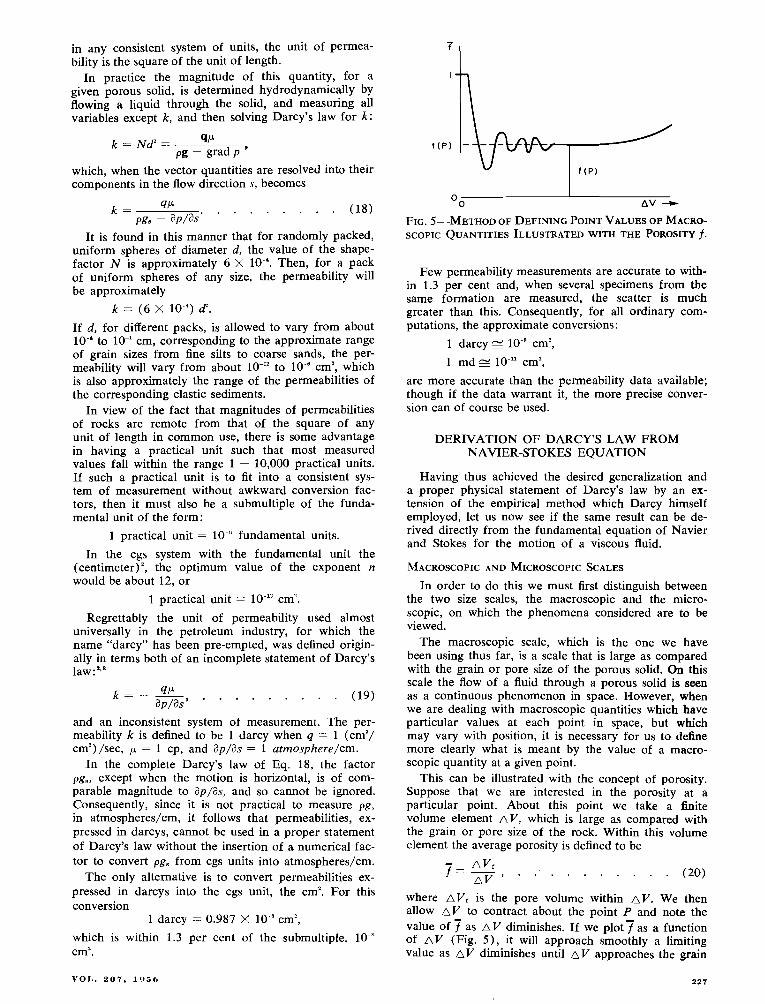
This can be illustrated with the concept of porosity. Suppose that we are interested in the porosity at a particular point. About this point we take a finite volume element AV, which is large as compared with the grain or pore size of the rock. Within this volume element the average porosity is defined to be
where AVr is the pore volume within AV. We then allow AV to contract about the point P and note the value of 7 as AV diminishes. If we plot7 as a function of a V (Fig. 5) , it will approach smoothly a limiting value as AV diminishes until AV approaches the grain

or pore size of the solid. At this stage 7 will begin to vary erratically and will ultimately attain the value of either 1 or 0, depending upon whether P falls within the void or the solid space.
However, if we extrapolate the smooth part of the curve of 7 vs A V to its limit as A V tends to zero, we shall obtain an unambiguous value of f at the point P. We thus define the value of the porosity f at the point P to be
where "extrap limn signifies the extrapolated limit as ob- tained in the manner just described.
By an analogous operation the point value of any other macroscopic quantity may be obtained, so that hereafter, when such quantities are being considered, their values will be understood to be defined in the foregoing manner, and we may state more simply:
lim - Q ( P ) =
lim - Q ( P ) = . . .
lim - Q ( P ) ' -
AS-. 0 Q ( A S , , ] where the quantity of interest is a function of a volume, an area, or a length, respectively.
The microscopic scale, on the contrary, is a scale commensurate with the grain or pore size of the solid, 51.1t still large as compared with molecular dimensions c r of tk.c motional irregularities due to Brownian or molecular movements.
Let us next consider the steady, macroscopically recti- linear flow of an incompressible fluid through a porous solid which is macroscopically homogeneous and iso- tropic with respect to porosity and permeability. We shall then have the fluid flowing with a constant macro- scopic flow rate q under a constant impelling force per unit of mass E, and in virtue of the isotropy of the system, we shall have
. . . . . . . . . . . q = a E , (23)
where a is an unknown scalar whose value we shall seek to determine.
Then, choosing x-, y-, and z-axes,
and q x = uE,, qY = oEy . . . . . . . . . . . (25) q . = uE, , 1
where i , j, and k are unit vectors parallel to the x-, y-. and z-axes, respectively, and the subscripts signify the corresponding scalar components of the vectors.
Further, there will be no loss of generality, and our analysis will be somewhat simplified, if we choose the x-axis in the macroscopic direction of flow. Then
q = = i q x ; E = i E , , . . . . and I (26)
qr = q . = O ; E , = E, = 0 .
Next, consider the microscopic flow through a macro- scopic volume element AV of sides Ax, ~ y , and AZ. The void space in such an element will be seen to be an intricately branching, three-dimensional network of flow channels, each of continuously varying cross section. A fluid particle passing through such a system will follow a continuously curving tortuous path. Moreover, the speed of the particle will alternately increase and de- crease as the cross section of the channel through which it flows becomes larger or smaller. Such a particle will accordingly be seen to be in a continuous state of accel- eration with the acceleration vector free to ascirme any possible direction in space.
Consider now the forces which act upon a hmall vol- ume element dV of this fluid. By Newton's second law of motion
where dm is the mass of the fluid, a the acceleration, and TdF is the sum of all the forces acting upon the fluid contained within dV. There are many ways in which these forces may be resolved, but for present purposes it will be convenient to resolve them into a driving or impelling force dF, and a resistive force arising from the viscous resistance of the fluid element to deformation, dF,. Eq. 27 then becomes
By the principle of D'Alembert we may also introduce a force dF. = - dm a, which is the inertial reaction of the mass dm to the acceleration a, and with this substitu- tion Eq. 28 becomes
Of these forces, dF,, which is imposed from without and does not depend primarily upon the motion of the fluid, may be regarded as the independent variable. The forces dl?. and dF, both owe their existences to the fluid motion, and their effect is to impede that motion.
The relation of the separate terms of Eq. 29 to the externally applied forces and the fluid motion are given by the equation of Navier and Stokes, which in vector form may be written as follows:
P [g - ( l / p ) grad PI dV = p (Dv/Dt) dV - [V 'V + (1/3) VV.v] dV, . (30)
in which v is the microscopic velocity, and p = - (1/3) (ox + a, + o,) is the microscopic pressure at a point. The a's are normal components of microscopic stress.
The expression Dv/Dt is the total derivative with re- spect to time of the velocity v, and is equal to the accel- eration a. This can be expanded into
P E T R O L E I J M T H A N S . 4 C T l O S S . A l M E

in which the term &/at signifying the rate of change of the velocity at a particular point is zero for steady motion. The expression V.v, in the last term of Eq. 30, is the divergence of the velocity; and for an incompressible fluid this also is zero.
Since the flow being considered is the steady motion of an incompressible fluid, Eq. 30 simplifies to
p [g - ( l / ~ ) grad p] dV = p (VVV) dV - p (v'v) dV . . . (31)
Eq. 31 expresses the relation of the fluid velocity and its derivatives in a small microscopic volume element to the applied force dF,, acting upon that element. If we could integrate the three terms of this equation with re- spect to the volume, over the macroscopic volume AV, and then convert the results into equivalent macroscopic variables, our problem would be solved. In fact the inte- gration of the first two terms presents no difficulty. The total driving force on the fluid content of the volume AV, as obtained by integrating the microscopic forces dF,,, is:
F,, - .j dF, = .S (pg - gradp) dV fAV
= ( p g - g r a d p ) f A V , . . . . . (32) - where grad p is the volumetric average of the microscopic grad p over the fluid volume f n v .
From the macroscopic equations, the driving force F, is given by:
F,, = p f A V E = plg - ( l / p ) g r a d p l f n v . (33)
Then by combining Eqs. 32 and 33, - .S (pg - grad P) dV = (pg - grad p ) f n V
fAV = P f A v [g - ( l / p ) grad P I , (34)
from which it is seen that the macroscopic grad p is equal to the volumetric average, grad p, of the microscopic grad p.
Integrating the inertial term:
F,, = JdF, = p J v.Vv dV
Since there is no net gain in velocity with macroscopic distance, each separate integral of the expanded form of Eq. 35 is equal to zero, and we obtain for the volunle ele- ment AV,
F : , = , I ' d F ; , = = O . . . . . . . (36)
Then, in virtue of Eq. 36,
.(' dF.. = p J' V'V dV = - F,, . (37) fAV
Ordinarily the evaluation of
(' O'V dV f d v
would require a detailed consideration of the geometry of the void space through which the flow occurs and of the flow field within that space. This difficulty can be circumvented, however. and the integral evaluated except
for a dimensionless factor of proportionality, provided the flow field i . ~ kinematically similar for different rates of flow.
Consider two flow systems consisting of two geometri- cally similar porous solids through which two different fluids are flowing. The criterion of geometrical similarity is that if I, and I, are any corresponding lengths of the two systems, then for every pair of such lengths
l2/I1 = I,. = const . . . . . . . (38)
The criterion of kinematic similarity is that if v, and v2 are the velocities at corresponding points in the two sys- tems, the two velocities must have the same direction and their magnitudes the ratio
Then, since the forces dF, and dF, acting upon a fluid element are each determined by the velocities and the fluid density, or viscosity, and dF, is determined by dF, and dF,., if the fluid motions of the two systems are kine- matically similar, all corresponding forces will have the same directions and their magnitudes the same ratio (Fig. 6) .
Thus
Since only two of the three forces are independent, we need to consider the ratios of only the first two, and, by reciprocation,
indicating that for each system the ratio of the inertial to the viscous force must be the same.
From Eq. 3 1
In Eq. 41 v.Vv expands into the sum of a series of terms, each of the form u au/ax, which is a velocity squared divided by a length. In Eq. 42 V'V expands into a series of terms, each of the form a'u/ax2, which is a veloc- ity divided by the square of a length. Then, since the ratios of all corresponding velocities and of all corre- sponding lengths of the two systems are constant, we may choose any suitable velocity and any convenient length. We accordingly choose for the velocity the macro- scopic flow rate q whose dimensions are [ L Y - ' T-'], or [LT']. For the characteristic length we choose d, which must be some convenient statistical length parameter of the microscopic geometry of the system. With these sub- stitutions the first two terms of Eq. 39 become
and, by reciprocation, Eq. 40 becomes

The dimensionless quantity (qd)/(p/p) is the Reyn- olds number R of the system, which, as seen from its deri- vation, is a measure of the ratio of the inertial to the vis- cous forces of the system. Our criterion for kinematic similarity between the two systems thus reduces to the requirement that
Now let us specialize the two systems by making
d! = 4, p2 = PI, pz = p~ , which is equivalent to requiring the same fluid to flow through the same porous solid at velocities, qz and q,. However, when these values are substituted into Eq. 44, we obtain
q.! = 47 , indicating that, in general, when the same fluid flows through a given porous solid at two different rates, the resulting flow fields cannot be kinematically similar.
However, since dF, is proportional to q2 and dF, to q, then as q is decreased dF, diminishes much more rapidly than dF,. Consequently there must be some limiting value of q = q* , or of R = R*, at and below which the inertial force dF. is so much less than the viscous force d F , that the effect of the former is negligible as compared with the latter. For flow in this domain we may then write
dF, = - dF,, ;
and the force ratios become
whereby kinematical similarity is maintained for all rates of flow q < q* .
With this result established let us now return to the integration of dF, over the volume element f n V .
j' d F , = p [i J V'U d V + j .f V ' V d V fhv fn v fn v
. . . . . . . + k J ~ ~ w d V ] . (47) fn v
In virtue of the fact that, by our choice of axes, q, and q, are both zero and there is no net flow in the y- or z- direction, the last two integrals to the right are both zero, and Eq. 47 simplifies to
. . . . . . J dF, = i [ L J V ' u d V . (48) fn v fn v
From our earlier discussion, so long as the flow remains kinematically similar for different rates, the quantity V ' U ,
which is a velocity divided by the square of a length, is related to the macroscopic parameters by
where CY is a dimensionless constant of proportionality for the element d V but has a different value for each different element of volume.
Substituting Eq. 49 into Eq. 48 then gives
where 1 / N is the average value of a over f~ V.
Substituting this result into Eq. 37, we obtain
~ [ g - il/p) grad pl f n V = - , I ' d ~ , . = Nd' C f a v ,
which is the derived Darcy's law in the same form as Eq. 16 deduced earlier from empirical data.
The direct derivation of Darcy's law from fundamen- tal mechanics affords a further insight into the physics of the phenomena involved over what was obtainable from the earlier method of empirical experimentation. It has long been known empirically, for example, that Darcy's law fails at sufficiently high rates of flow, or at a Reyn- olds number, based on the mean grain diameter as the characteristic length, of the order of R = 1 .'
At the same time one of the most common statements made about Darcy's law has been that it is a special case of Poiseuille's law; and most efforts at its derivation have been based upon various models of capillary tubes or of pipes. It also has been known since the classical studies of Osborne Reynoldsvn 1883 that Poiseuille's law fails when the flow makes the transition from laminar to turbulent motion, so the conclusion most often reached as to the cause of the failure of Darcy's law has been that the motion has become turbulent.
From what we have seen, this represents a serious mis- interpretation and lack of understanding of Darcy's law. In the Darcy flow each particle moves along a continu- ously curvilinear path at a continuously varying speed, and hence with a continuously varying acceleration; in the Poiseuille flow each particle moves along a rectilinear path at constant velocity and zero acceleration. There- fore, instead of Darcy's law being a special case of Poi- seuille's law, the converse is true; Poiseuille's law is in fact a very special case of Darcy's law. Another special case of Darcy's law is the rectilinear flow between paral- lel plates.
Consequently deductions concerning the Darcy-type flow made from the simpler Poiseuille flow are likely to be seriously misleading. The deduction that the Reynolds number at which Darcy's law fails is also the one at which turbulence begins is a case in point. We have seen that the cause of the failure of Darcy's law is the distortion that results in the flowlines when the velocity is great enough that the inertial force becomes significant. This occurs at a very slow creeping rate of flow which, for water, has the approximate value of
corresponding to R* = 1, when d is the mean grain diameter.
Thus when d = lo-' cm Darcy's law fails at a flow rate q s 1 cm/sec.
Since this represents the threshold at which the effects of inertial forces first become perceptible, and since tur- bulence is the result of inertial forces becoming predom- inant with respect to resistive forces, it would be inferred that the incidence of turbulence in the Darcy flow would occur at very much higher velocities or at very much higher Reynolds numbers than those for which linearity between the flow rate and the driving force ceases. That this is in fact the case has been verified by visual obser- vations of the flow of water containing a dilute suspension of colloidal bentonite through a transparent cell contain- ing cylindrical obstacles. This system, when observed in
P E T R O L E U M T R A Y S A C T I O N S , A I M E

polarized light, exhibits flow birefringence which is sta- tionary for steady laminar flow but highly oscillatory when the motion is turbulent. Observations of only mod- erate precision indicate that the incidence of turbulence occurs at a Reynolds number of the order of 600 or 700 , or at a flow velocity of the order of several hundred times that at which Darcy's law fails.
In both procedures used thus far, the factor N has emerged simply as a dimensionless factor of proportional- ity whose magnitude is a function of the statistical geo- metrical shape of the void space through which the flow occurs. For systems which are either identically or sta- tistically similar geometrically, N has the same value. Beyond this we have little idea of the manner in which N is related to the shape or of what its numerical magni- tude should be, except as may be determined by experi- ment. Let us now see if the value of N, at least to within an order of magnitude, can be determined theoretically.
Since we have already seen in Eq. 50 that 1/N = u, where a is the factor of proportionality between the macroscopic quantity q/d2 and the microscopic quantity v Z u , it follows that in order to determine the magnitude of N we must first determine that of the average value of V'U. For this purpose, with the fluid incompressible, the macroscopic flow parallel to the x-axis, and the inertial forces negligible, only the x-component of the Navier- Stokes Eq. 3 1,
needs to be considered. When this is integrated with re- spect to the volume over the fluid space faV, it becomes
Of the three integrals to the right, the first, which rep- resents the expansion of the fluid in the x-direction, is zero; and from symmetry, the last two, both being the integrals of derivatives with respect to axes at right angles to the flow, are equal to each other. In consequence, Eq. 53 is reduced to the simpler form:
in which a'u/ay2 is the average value of a3u/ay3 throughout - the macroscopic volume element. Solving this for a2u/ay' then gives
Our problem now reduces to one of attempting to determine the average value of a'u/ay2 for the system in terms of the kinematics of the flow itself. If we extend any line through the system parallel to the y-axis, this line will pass alternately through solid and fluid spaces. At each point on the line in the fluid space, there will be a particu- lar value of the x-component u of the velocity, which will be zero at each fluid-solid contact, but elsewhere will have finite, and usually positive, values giving some kind of a velocity profile across cach fluid gap. If this profile for each gap could be determined, then we could also com- pute a2u/ayz at each point on the line and thereby detcr- - mine a'u/ay2 for the line, which, in a homogeneous and
isotropic system, would also be the average value for a volume.
To attempt to do this in detail would be a statistical undertaking beyond the scope of the present paper. As a first approximation, however, we may simplify the prob- lem by assuming:
1. That all the gaps are equal and of width 2 x , where 7 is the average half-width of the actual gaps.
2. That through each gap the velocity profile sat- isfies the differential equation
a 2 ~ / a y 2 = a2u/ay' = - c . . . . ( 5 5 )
3. That the total discharge through the averaged gaps is the same as that through the actual gaps.
The velocity profile for the averaged gaps can then be obtained by integrating Eq. 55 with respect to y. Taking a local origin of coordinates at the middle of the gap, and integrating Eq. 55 twice with respect to y, we obtain
u = - C y 2 / 2 + A y + B , . . . . . ( 5 6 )
in which A and B are constants of integration. Then, supplying the boundary conditions, u = 0 when y = - & A, gives -
O = - c A ' / ~ % A ~ + B
from which
A = o ; B = c ~ ' / ~ . Substituting these into Eq. 56, we obtain
as the equation of the parabolic profile of the aver- aged velocity across the averaged gap.
The mean value, u, of u across this gap is given by
. . . . . . . . . . . . . . . ( 5 8 )
Then, replacing C by ( 1 / 2 p ) ( ~ g , - ap/ax) from Eqs. 55 and 54, we obtain
- - A ' P u = -- 6 P
[ ~ . - ( l / ~ ) a p / a x i . . . . ( 5 9 )
This can be converted into terms of the macroscopic velocity, q,, by noting that for a macroscopic length of line 1 normal to the flow direction
- q, 1 = 211 ZA,
or - - q. = 21.4 ( Z A / l ) = u f , . . . . . . ( 6 0 )
where f is the porosity. With this substitution Eq. 59 becomes
or, more generally,
which is a statement of Darcy's law that is valid to the extent of the validity of the averaging approxima- tion used in its derivation.
V O L . 207, 1 9 5 0
In this, it will be noted that the geometrical factor (f/6) A' represents the permeability, so that
k z (f/6) x2 = N; X' , or
N , - r f /6 . . . . (63)
where N,- is the shape factor corresponding to as the characteristic length of the system.
The mean half gap-width 1 along a linear traverse can be determined in either of two ways. The most ob- vious way is by direct observation by means of microme- ter measurements along rectilinear traverses across a plane section of the porous solid.
Of greater theoretical interest, however, is an indirect method due to Corrsin.' Instead of a line, let a rec- tangular prism of cross-sectional area S2, where 6 can be made arbitrarily small, be passed through a porous solid which is macroscopically homogeneous and iso- tropic. This prism will pass alternately through solid segments and void segments. Let n be the number of each which is traversed per unit length. Then the num- ber of intersections with the solid surface per unit length will be 2n, and if a is the average area of the solid surface cut out by the prism at each intersection, the total area per unit length, dp, will be
If a parallel family of such prisms is made to fill all space, the number per unit area perpendicular to the axis of the prisms will be I/F2, and the solid surface in- tersected per unit volume will be
In addition, the total length of the void spaces per unit length of line will be
Substituting the value of n from Eq. 66 into 65 and solving for then gives
, -
Since f and /3 can be measured, the value of X could be determined if ;/a2 were known.
The ktter can be determined in the following man- ner: A homogeneous and isotropic distribution of the internal surface S, inside a macroscopic space, implies that if all equal elements riS of the surface were placed without rotation at the center of a reference sphere, their normals would intersect the sphere with a uni- form surface density. Then, with the normals fixed in direction, if the surface elements were all moved equal radial distances outward, at some fixed radius they would coalesce to form the surface of a sphere. If the prisms of cross-sectional area 6', parallel to a given line, were then passed through this sphere, the aver- age value of a/S' would be
znd, when the summation includes one whole hem- isphere,
- - area of hemisphere - 2nr' - a/S' = n / S 1 = ---- 2 . area of diametral plane n 4
(69) . . . . . . . . . . . . . . Introducing this result into Eq. 67 then gives -
x = 2f /P . . . . . . . . . . . (70)
A method for measuring /3 has been described by Brooks and Purcell,' but for present purposes the data on randomly packed uniform spheres, for which ,f3 can be computed, will suffice. For such a system, with n spheres per unit volume,
area of spheres - - n.4.rrr3 - -- 3 ( 1 - f )
= total volume n 4nr' r -- 1 - f ' 3
where d is the sphere diameter. Then, introducing this result into Eq. 70, we obtain
for packs of uniform spheres
and
In order to compare the value of N;, correspond- ing to the characteristic length x, with N,, correspond* ing to the sphere diameter d, we must first establish the relation between N;: and N1. This can be done by noting that, by definition,
where k is the permeability of the system. Consequently
N; = N., ( 8 / P ) . . . . . . . . (74)
Then, introducing the value of 8/? f m Eq. 73 into Eq. 74, gives for a pack of unifonn spheres
The value of N,, for well-rounded quartz sands, screened to nearly uniform sizes, has been determined by the author's former research assistant, Jerry Con- ner. Using packs of different uniform sands with mean grain diameters ranging from 1.37 X lo-' to 7.15 X lo-' cm, Conner made seven independent determina- tions of N,. The average value obtained was -
. . . . . . . . . N, = 6.0 X 10.' (76)
with individual values falling within the range between 5.3 X 10." and 6.7 X lo-'.
Conner did not determine the porosity, but the aver- age value of the porosity of randomly packed, uniform spherical glass beads found by Brooks and Purcell' was 0.37. Inserting this value of f, and Conner's value of N,,, into Eq. 75 then gives for the equivalent experi- mental value of h$:
N;=26.2Nd = 1.57 X 10.' . (77)
Comparing this experimental result with the approxi- mate theoretical result of Eq. 63, it will be seen that
N; (theoretical) - - f/6 = 4 . . (78)
N ; (observed) 1.57 X lo-'
P E T R O L E U M T R A N S A C T I O N S , A I M E

Since our object at the outset was merely to gain some insight into the nature of the shape-factor N occurring in Darcy's law, no particular concern is to be felt over the discrepancy in Eq. 78 between the ob- served and the theoretical values. All that this really indicates is that the system of averaging required should be better than the oversimplified one actually used. For a more complete analysis, account needs to be taken of the frequency distribution of the half gap-width A, and also of the functional relation between u and A. The fact that our approximate analysis yields a result in er- ror by only a factor of 4 makes it appear promising that if account is taken of the variability of A and of - u as a function of A, much better approximations may be obtainable.
DARCY'S LAW FOR COMPRESSIBLE FLUIDS
Our analysis thus far has been restricted to the flow of incompressible fluids for which the divergence term, - (1/3) p V V v, could be eliminated from the Navier- Stokes equation. For the flow of a compressible fluid, this term must be retained, and with the flow parallel to the x-axis.
of which the last two terms are equal to zero, leaving
Here, azu/ax' represents the gradient of the divergence of the velocity in the x-direction, or the rate of the fluid expansion. Should this term be of the same order of magnitude as a2u/ay', and if the flow of a gas through the porous system is otherwise similar to that of a liquid, then the viscous resistance to a gas should be greater than that for a liquid of the same viscosity.
To compare the two terms a'~l/ax' and a2u/ay', it will be noted that each is of the form: velocity/(length)'. We have already seen that
indicating that the magnitude of this term is determined by the fact that large variations of u in the y-direction take place within the width of a single pore. Compar- able variations of u in the x-direction, however, due to the expansion of the fluid, occur only in fairly large macroscopic distances. Consequently, we may write
where I is a macroscopic distance. The ratio of the two terms is accordingly
Then, since lL > > h', it follows that the additional frictional drag caused by the divergence term is negli- gible, and this term may be deleted from the equation.
We conclude, therefore, from this approximate analy- sis, that Darcy's law in its differential form is the same for a gas as for a liquid, provided that the flow
behavior of a gas in small pore spaces, other than ex- pansion, is similar to that of a liquid.
It has been conclusively shown, however, by L. J . Klinkenberg8 that the two flows are not similar, and that, in general, k, , the permeability to gas based on the assumed validity of Darcy's law for gases, is not equal to k , , the permeability to liquids; and, in fact, is not even a constant.
In the case of the flow of a liquid through small pores, the microscopic velocity v becomes zero at the fluid-solid boundary; for gas flow, on the contrary, there exists along the boundary a zone of slippage of thickness 6, which is proportional to the length of the mean-free path of the molecules. Consequently the gas velocity does not become zero at the boundaries, and the frictional resistance to the flow of gas is less than that for a liquid of the same viscosity and macro- scopic velocity.
Since 6 is proportional to the mean-free path, it is also approximately proportional to l/p. Consequently when the gas permeability, k,, of a given porous solid is determined with the same gas at a number of differ- ent mean pressures, the resulting values of k, , when plotted as a function of l/p, give a curve wnich is ap- proximately linear with l/p. Moreover, different gases, having different mean-free paths, give curves of differ- ent slopes. The limiting value of k , as l /p + 0, or as p becomes very large, is also equal to k l , the permea- bility obtained by means of a liquid (Fig. 7 ) .
In view of this fact it is clear that, in general, the flow of gases through porous solids is not in accord- ance with Darcy's law. However, from Klinkenberg's data, at pressures greater than about 20 atmospheres (2 X lo7 dynes/cm2, or 300 psi), the value of k , differs from k , by less than 1 per cent. Therefore, since most oil and gas reservoir pressures are much higher than this, it can be assumed that gases do obey Darcy's law under most reservoir conditions.
FIELD EQUATIONS O F THE FLOW O F FLUIDS THROUGH POROUS SOLIDS
The establishment of Darcy's law provides a basis upon which we may now consider the field equations that must be satisfied by the flow of fluids through porous solids in general, three-dimensional space. This
0 2 0 4 0 6 0 6 1 0 1 2 1 4
RECIPROCAL M E A N P R E S S U R E lATM I-'
FIG. 7-VARIATION AS A FUNCTION OF 1/p OF THE APPAR- ENT PERMEABILITY OF A GIVEN SOLID AS DETERMINED BY THE DIFFERENT GASES. THE VALUE OF 2.75 MD, AS
( l / p ) TENDS TO 0, DIFFERS BUT SLIGHTLY FROM THAT
OF 2.55 M D OBTAINED USING A LIQUID (AFTER L. J. KLINKENBERG, API Drill. and Prod. Prac.. 1941).

problem is complicated, however, by the fact that the fluids considered may be either of constant o r of var- iable density; that one or several different fluids, either intermixed or segregated into separate macroscopic spaces, may be present simultaneously; and that all de- grees of saturation of the space considered are possible.
The problem of dealing with such cases becomes tractable when we recognize that the behavior of each different fluid can be treated separately. Thus, for a specified fluid, there will exist at each point in space capable of being occupied by that fluid a rnacroscopic force intensity vector E, defined as the force per unit mass that would act upon a macroscopic element of the fluid if placed at that point. In addition, if the fluid does occupy the space, its macroscopic flow rate at the given point will be indicated by the velocity vec- tor q, the volume of the fluid crossing unit area nor- mal to the flow direction in unit time.
We shall thus have for each fluid two superposed fields, a field of force and a field of flow, each inde- pendently determinable. The equations describing the properties of each of these fields, and their mutual in- terrelations, comprise the field equations of the system; these in turn, in conjunction with the boundary condi- tions, determine the nature of the flow.
We have seen already that the force per unit mas5 is given by
. . . . . E = g - ( l / p ) grad p , (15)
and the force per unit volume by
Either of these force vectors could be used, and either is determinable from the other, but before choosing one in preference to the other, let us first consider the properties of their respective fields, of which the most important for present purposes is whether o r not the field has a potential. T o simplify our analysis we will make the approximations that
. . . . . . . . . . g = cons t , ( 8 2 )
and for chemically homogeneous liquids under the range of temperatures and pressures normally encoun- tered in the earth to drillable depths,
. . . . . . . . . . = const. ( 8 3 )
For gases, on the other hand, we shall h a w an equa- tion of state
p = f ( p , 7 ' ) . . . . . . . . . (84)
where T is the absolute temperature. The vector E has a particular value at each point in
space and the ensemble of such values comprises its vector field. The criterion of whether this field has a potential, that is to say, of whether
E = - grad a], where is a scalar field, is whether the field E is irro- tational, which can be determined from its curl. From Eq. 15,
curl E = curl [g - ( l / p ) grad p] = 0 r: g - 0 X [ ( l / p ) 0 p l .
As is well known, the gravity field is irrotational even without the assumption that g = const, so that
0 A g = 0. Also
- 0 x [ ( l / p ) O p l = - O ( l / p ) x O p - ( ] / P I O x V P = - O ( l / p ) X O p .
Consequently curl E = - O ( l / p ) X O p = O p X O ( l / p ) ,
. . . . . . . . . . . . . . . ( 8 5 ) so that
curl E = 0 when V p X O ( l / p ) = 0 . ( 8 6 ) Therefore, in order for the field to be irrotational, and hence derivable from a scalar potential, it is necessary either that O p = 0, corresponding to constant pres- sure, o r V ( l / p ) = 0, corresponding to constant den- sity, o r else that the vectors O p and O ( l / p ) be collinear, corresponding to a coincidence of the surfaces of equal density and equal pressure.
The second of these three cases is satisfied by a liquid of constant density, and the third by a gas whose density is a function of the pressure only, such as oc- curs under either isothermal o r adiabatic conditions. For the general case, however, of a gas for which p = f ( p , T ) , and the surfaces of equal temperature do not coincide with those of equal pressure, then the sur- faces p = const will also not coincide with the surfaces p = const and we shall have two intersecting families of surfaces, ( l / p ) = const, and p = const, for which Eq. 8 5 applies.
This is the condition corresponding to thermal con- vection, and the fluid will have a convective circula- tion in the direction that will tend to bring the surfaces of equal density into coincidence with those of equal pressure, with the less dense fluid uppermost.
Hence, subject to the condition that either p = const, o r 11 = f ( p ) ,
. . . c u r l E = O a n d E = g r a d @ . ( 8 7 )
The value of @ at any arbitrary point P in space Fig. 8 ) is then obtained by
P + ( P ) = @ ( P o ) - J E, ds
Po 1
where the integral from Po to P is taken along any path 3, Then by setting @ ( P o ) = 0 when z = 0 and p,, = 1 atmosphere, we obtain
where p is now the gauge pressure, o r the absolute pres- sure less 1 atmosphere.
If the fluid is incompressible and chemically homogen- eous, this reduces to the simpler form
For this case, if a manometer is tapped into the sys- tem at the point P , the height h above the level z = 0, to which the liquid will rise, will be
P E T R O L E I l M T R A N S A C T I O N S , A l M E

FIG. 8-THE POTENTIAL @ AS A LINE INTEGRAL OF THE
FIELD OF FORCE E.
from which it follows that
in agreement with our earlier definition of @ in Eq. 14. If the fluid is incompressible and chemically inho-
mogeneous, as in the case of water of variable salinity, the density p will not be a function of pressure only, and, in general, surfaces of constant density will not be parallel to surfaces of constant pressure. For such a system curl E # 0, and no potential exists.
We thus see that, with the exception of cases of ther- mal convection, and of inhomogeneous liquids of var- iable density, the fields E for both liquids and gases are irrotational and are derivable from a potential Q,. Since E is a force per unit of mass, then is an energy per unit of mass, and represents the work required to transport the given fluid by a frictionless process along a prescribed (p, T)-path from a standard position and state to that of the point considered. Surfaces 9 = const are accordingly equipotential surfaces, or surfaces of constant energy of position, and the fluid will tend to flow from higher to lower potentials or energy levels.
The field of force per unit volume, H, can he dis- posed of summarily. Since
H = pg - grad p , then
curl H = V X (pg) - v X ~p = V p X g + p V X g - V X V p .
But, since V X Vp and V X g are each zero, then
curl H = ~p X g . . . . . . . . (93)
This is zero only when p is constant or when the sur- faces of constant density are horizontal. The last con- dition never occurs except when the fluid is at rest or when the motion is vertical. Hence, for motion in any direction other than vertical, the field of the vector H does not have a potential except when the density of the fluid is constant. For the special case of constant density,
H = - grad II , . . . . . . . . . where
(94)
rI = pa = pgz + p . . . . . . . . (95) is the energy per unit volume of the,fluid at any given point.
In view of the fact that the field E has a potential for both liquids and gases under the conditions specified above, whereas, in general, the field H has a potential
only for the special case of liquids of constant density, then there is no advantage in using the latter in pref- erence to the former, and henceforth it shall be dropped from further consideration.
The generality of the field of force, as herein de- fined, merits attention. The force vector E for any given fluid not only has values in space occupied by that fluid, but also in any space capable of being occupied by the fluid. At a point in air, for example, the force E, for water would be
E w = g - ( l/pw) grad P,
and since, in air, grad p is pair g, then
The field E for a given fluid thus extends throughout all space of continuous permeability. When several fluids are to be considered, then at each point in space there will be a different value of E, for each separate fluid, given by:
El = g - ( l /p,) grad P , 1 E 2 = g - ( l l p z ) g r a d p 9 . . . . (97) . . . . . . . . . t E,, = g - (l/p,) gradp . ]
The vectors E for the separate fluids of different den- sities will differ among themselves, both in magnitude and direction, but will all fall in the same vertical plane, that defined by g and - grad p (Fig. 9) .
Similarly the potentials of different fluids at the same point will be:
where p,, p,, . . . p,, are the variable densities of the sep- arate fluids.
Since the equipotential surfaces for the separate fluids must be normal to the respective vectors E, then it fol- lows that the equipotential surfaces of different fluids passing through a given point will not be parallel to one another, although they will all intersect along a line normal to the (g, - grad p)-plane.
We have already defined the flow vector q for a space which is entirely filled with a single fluid. For a space which is incompletely filled with a single fluid, or is occupied by two or more intermixed fluids, then there will be two or more superposed flow fields, not in general in the same direction, and a separate value of q for each separate fluid.
The principal condition which must be satisfied by the field of flow independently of the field of force is that it must be in accord with the principle of the con- servation of mass. Thus, if a closed surface, S, fixed with respect to the porous solid, is inscribed within the field of flow, then the total net outward mass flux of any given fluid in unit time will be equal to the diminu- tion of the mass of that fluid enclosed by S, assuming that processes which create or consume the given fluid are forbidden.
This condition is expressed by

where q,, is the outward-directed normal component of q, and m the mass enclosed (Fig. l o ) .
In the case of a space completely saturated with the given fluid, by dividing the integral (Eq. 99) by the volume V and then letting V tend to zero, we obtain
lim 1 1 am div pq = + JiJ' pq,, dS = - - - v at '
which is the rate of loss of mass per unit macroscopic volume at a given point. Then, since
am/at - fv (ap/at) . Eq. 100 becomes
which is the so-called "equation of continuity" of the flow. If the motion is steady, then ap/at is zero, and the equation simplifies to
div pq = 0 . . . . ( 102)
When this is expanded it becomes
and when p is constant over space, corresponding to the flow of a homogeneous liquid, V p = 0, and
d i v q = O . . . . . . . . . (103)
FIG. 9-FORCE VECTORS E A T THE SAME POINT CORRE- SPONDING TO FLUIDS OF DIFFERENT DENS~TIES.
In a space completely saturated by a aingle fluid, the field of flow and the field of force are linked to- gether by Darcy's law
which, in those cases for which curl E = 0, becomes
. . . . . . . . q = - u grad <I,. (105) If the solid is isotropic with respect to permeability,
the conductivity u is a scalar and the flowlines and the lines of force will coincide; if the solid is anisotropic, u
will be a tensor and E and q will then differ somewhat in direction except when parallel to the principal axes of the tensor.
Limiting our discussion to isotropic systems, by tak- ing the curl of Eq. 105, we obtain
Then, since the last term to the right is zero, this be- comes
. . . . . curl q = - V U X V@ , (106)
which is zero only when u is constant throughout the field of flow. Therefore, in general,
curl q f 0 , . . (107)
and this circumstance precludes the derivation of the flow field from an assumed velocity potential, for, with the exception of the flow of a fluid of constant density and viscosity in a space of constant permeability, no such function exists.
The flow of a given fluid through a porous solid incompletely saturated with that fluid is equivalent to flow through a solid of reduced permeability, because the space available to the flow diminishes as the sat- uration decreases. For saturations greater than some critical minimum value, the flow obeys Darcy's law subject to the permeability having this reduced, o r so- called, "relative-permeability" value. Thus, with two interspersed but immiscible fluids in the same macro- scopic space,
q, = UUI El = U,, [g - (l/p,) grad el , . , qz = u,? E2 = url [g - ( l / p J grad P I ,
where un and ur2 are the relative conductivities of the two fluids.
It will be noted that, except for vertical motion, E, and E, are not parallel. Consequently the two force fields and flow fields will be, in general, transverse to one another.
Pioneer work on relative permeability as a function of saturation was done on the single fluid, water, by L. A. Richards" in 1931. Subsequently studies of the simultaneous flow of two or more fluids were initiated by Wyckoff and Botse t , ' bnd by Hassler, Rice, and Leernan" in 1936. Since that time many other such stud- ies for the systems water-oil-gas have been published.
One flaw which has been common to most of these tnultifluid experiments has been that the experimental arrangements and their interpretation were usually based upon the premise that the flowlines of the various components are all parallel and in the direction
P E T R O L E U M T R A X S A C T I O S S , A l M E

- grad p. Since this is far from true, there is some ques- tion of the degree of reliability of the results of such experiments. Even so, the existing evidence indicates that for saturations greater than some critical minimum the flow obeys Darcy's law in the form given in Eqs. 1 0 8 . For saturations less than this limit, there should still be a general drift of discontinuous fluid elements in the direction of the field E, but with, as yet, no well- defined relationship between q and E.
The migration of petroleum and natural gas, through an otherwise water-saturated underground environment, from an initial state of high dispersion to final positions of concentration and entrapment, constitutes an exam- ple of the latter kind.
Although the present paper does not permit of th& elaboration, practically everything that is now known concerning the flow of fluids in a porous-solid, three- dimensional space is deducible from the foregoing field equations. The equations for the flow of an incom- pressible fluid are of the same form as those for the steady conduction of electricity. Consequently the well- known solutions to the electrical equations can be ap- plied directly to analogous situations in fluid flow. The unsteady flow of a compressible fluid, when the force field is irrotational, is closely analogous, although some- what more complex, to the unsteady conduction of heat, and the solutions of the heat equations can be adapted with some modification to the analogous fluid-flow problems.
The fluid phenomena which are unique and have no counterpart in other more familiar field theory are those involving multiple fluids. If we consider the flow of two immiscible fluids of unequal densities, such as water and oil, interspersed in the same macroscopic space, we have seen from Eq. 9 7 that, in general, the force fields E, and E, of the two fluids will lie in the same vertical plane, but will have divergent directions, that for the less dense fluid being upward with respect to that for the more dense. As a consequence the two fluids will drift in these respective directions, and, in
response to suitable impermeable barriers, will tend to become completely segregated.
Once this segregation is achieved, for any further steady motion of either of the fluids, the interface will appear as an impermeable barrier. Across this in- terface, neglecting minor pressure differences due to capillarity, the pressure in the two fluids must be the same. Then, in case neither of the fluids is in motion, the interface will have to be horizontal, with the less dense fluid uppermost, since this is the only inclination of the surface for which the pressures on opposite sides can be the same.
When either or both of the fluids is in motion, how- ever, in a nonvertical direction, the vectors ( l / ~ , ) grad p and ( l / p , ) grad p will be inclined from the vertical, and the corresponding equipressure surfaces will be in- clined from the horizontal by the same amounts. At the interface every equipressure surface in one system must match that of the same value in the other.
At the same time, the flowlines in each system must be parallel to the interface so that the (E,, E,)-plane must be tangent to the interface. Consequently the in- terfacial surface and the flow patterns in the two sys- tems must mutually adjust themselves until these condi- tions are simultaneously satisfied before a steady state of flow becomes possible.
Of particular interest is the special case of this gen- eral situation wherein one of the two fluids is in motion and the other is completely static. In this case the equipressure surfaces in the static fluid are horizontal and surfaces having equal difference of pressure are equally spaced; whereas, in the moving fluid the equipres- sure surfaces are inclined downward in the direction of the horizontal component of the flow. Their lines of inter- section at the interface must accordingly be horizontal. Also, since the vector, grad p, lies in the same vertical plane as the vector E of the flowing fluid, it follows that the horizontal component of the flow direction must be parallel to the direction of steepest slope of the interface.
If we consider a vertical plane parallel to the flow direction and perpendicular to the interface, then in this plane the surfaces of constant pressure will appear as lines of constant pressure, inclined in the flowing fluid and refracting into the horizontal across the interface in the static fluid. Let the flowing fluid be denoted by the subscript 1 and the static fluid by the subscript 2. Then along the interface in the direction of the flow
( a p / a s ) , = ( a p / a s ) , . . . . . . . ,109)
In the static fluid
( a p / a s ) ? = - pzg sin 8 , . . . . . . ( 1 1 0 )
and consequently depends only upon the density p, and the angle of slope 0 of the interface, where 0 is posi- tive when the slope is upward in the flow direction.
In the flowing fluid, since
E = g , - ( l i p , ) ( a p i a ~ ) , , then
( a p / a s ) , = p,g, - p l ~
= - p,g sin 8 + p, (grad ~l),J .

Equating 1 10 and 1 I 1 then gives
p g sin B = p,g sin B - p, grad [I), 1 . which, when solved for sin 8, becomes
grad cD.1 . . . . (112) sin B = - --- g p2 - Pl
If the less dense fluid is flowing (Fig. 1 l a ) , p2 > p,, the term to the right will be positive, and the interface will tilt upward; if the more dense fluid is flowing (Fig. 1 lb ) , p, > p2, the term to the right will be negative, and the interface will tilt downward.
Eq. 112, derived earlier by Hubbert,","' is the funda- mental equation pertaining to fresh-water - salt-water relations along shore lines, and to oil-water and oil-gas interfacial relations such as water or gas coning during oil and gas exploitation. It is also the basic equation governing the underground positions of oil and gas en- trapment. If the water is static, accumulations of pe- troleum or of natural gas will occur beneath downwardly concave impermeable barriers, with the oil-water or gas-water interface horizontal. If the water is in mo- tion, as often is the case, the oil-water or gas-water in- terface will be inclined, and oil or gas may be trapped beneath structures completely unclosed in the hydro- static sense.
, , R E S U M E
In paying our respects to M. Henry Darcy on this centennial occasion, we stated at the outset that it should be our endeavor:
I. To show unequivocally what Darcy himself did and stated with respect to the relationship which now bears his name, and to give his results a more general, but still equivalent, physical formulation.
2. To derive Darcy's law directly from the funda- mental Navier-Stokes equation of motion of viscous fluids.
3. To develop, in at least their primitive forms, the principal field equations of the flow of fluids through porous solids.
These objectives have now been accomplished, and the result is that, despite a number of troublesome complexities such as those arising from thermal con- vection and from waters of variable salinity, the field theory of the flow of underground fluids is capable of being brought into the same kind of a comprehensive unification as that already achieved for the more fa- miliar phenomena of electrical and thermal conduction.
In closing it is pertinent to reiterate that Darcy's empirical formulation:
q = K (h, - h , ) / l ,
which, as we have seen is valid for flow of a homogen- eous liquid in any direction, is physically equivalent to the expressions:
From these it follows that fluids can and do flcw in any
\ S T A T I C F L U I D ( P I )
FIG. I I-INTERFACES BETWEEN FLOWING AND STATIC FLUIDS OF UNEQUAL DENSITIES. (a) UPWARD TILT IN
THE FLOW DIRECTION WHEN LESS DENSE FLUID IS FLOWING. (b) DOWNWARD TILT WHEN MORE DENSE
FLUID FLOWS.
direction whatever with respect to that of the pressure gradient.
So far as we have seen no error of any kind with re- spect to the flow of fluids through porous solids can be attributed to Henry Darcy; and the errors which have been alleged by various authors during recent years appear on closer inspection to have been those com- mitted by the authors themselves.
A C K N O W L E D G M E N T S
Since this paper is the result of some 20 years of intermittent reflection upon the phenomena encompassed by Darcy's law, the author is indebted to many people whose oral or written discussions of various aspects of the problems involved have contributed to his own understanding of them. He is particularly indebted, how- ever, to his current and recent colleagues who have been of direct assistance in the present study. These in- clude: Jerry Conner who made an extensive series of experiments verifying the author's earlier theoretical deductions; David C;. Willis who, in addition to reading critically the manuscript and assisting in the design of the illustrations, has been of invaluable assistance in the clarification of many difficult points; R. L. Chuoke and A. S. Ginzbarg who gave important mathematical assist- ance; and R. H. Nanz who made an extensive series of measurements of the gap-widths along linear traverses through randomly packed uniform spheres.
Any errors, however, are the author's own.
P E T H O L E I T M T R A Y S A C T I O Y S , A I M E

R E F E R E N C E S
I . Darcy, Henry: Les Fontaines Publiques de la Ville d e Dijon, Victor Dalmont, Paris (1856).
2. Wyckoff, R. D., Botset, H. G., Muskat, M., and Reed, D. W.: "The Measurement of the Permeabil- ity of Porous Media for Homogeneou.~ Fluids," Rev. Sci. Instruments ( 1933), 4, 394.
3. A.P.I. Code No. 27, "Standard Procedure for De- termining Permeability of Porous Media" (Tenta- tive), 1st Edition (Oct., 1935), American Petro- leum Institute.
4. Fancher, G. H., Lewis, J. A., and Barnes, K. B.: "Some Physical Characteristics of Oil Sands," Pennsylvania State College Mineral Industries Ex- periment Station Bulletin 12 (1933), 65.
5. Reynolds, Osborne: "An Experimental Investiga- tion of the Circumstances Which Determine Whether the Motion of Water Shall Be Direct or Sinuous and of the Law of Resistance in Parallel Channels," Philos. Trans. Royal Soc. London (1883), 174, 935; or Papers on Mechanical and Physical Subjects, University Press, Cambridge (1901), Vol. 11, 51.
6. Corrsin, Stanley: "A Measure of the Area of a Homogeneous Random Surface in Space," Quart. Appl. Math. ( 1954-1955), 12, 404.
7. Brooks, C. S., and Purcell, W. R.: "Surface Area Measurements on Sedimentary Rocks," Trans. AIME ( 1952), 195, 289.
8. Klinkenberg, L. I.: "The Permeability of Porous Media to Liquids and Gases," API Drill. and Prod. Prac. 1941 ( 1942), 200.
9. Richards, L. A.: "Capillary Conduction of Liquids Through Porous Mediums," Physics (1931), 1, 318.
10. Wyckoff, R. D., and Botset, H. G.: "The Flow of Gas-Liquid Mixtures Through Unconsolidated Sands," Physiss (1936), 7, 325.
11. Hassler, Gerald L., Rice, Raymond R., and Lee- man, Erwin H.: "Investigations on the Recovery of Oil from Sandstones by Gas Drive," Trans. AIME (1936), 118, 116.
12. Hubbert, M. King: "The Theory of Ground-Water Motion," Jeur. Geol . (1940), 48, 785.
13. Hubbert, M. King: "Entrapment of Petroleum Under Hydrodynamic Conditions," Bull. AAPG (1953). 37, 1954. **.*