dark detectors
TRANSCRIPT
MINI PROJECT REPORT
On
AUTOMATIC LIGHT CONTROL USING DARK DETECTORS Using
NE555 TIMER IC
Submitted in partial fulfillment of the requirements for the award of
The Degree of Bachelor of Technology In
Electronics & Communication Engineering
Under the guidance of
Mr. NEELABH TIWARI
Submitted by
SHIV PRATAP SINGH (1205431094)
SUMIT KUMAR PRAJAPATI (1205431106)
Babu Banarasi Das National Institute of Technology and Management
(Affiliated to U. P. Technical University, Lucknow)
SESSION (2015 - 2016)
iii
ACKNOWLEDGEMENT
It is with profound gratitude that I express my deep indebtedness to all the teacher of BBDNITM
without whose support and guidance it would not have been possible for this project to have
materialized and taken a concrete shape. I owe my personal thanks to my team mate Sumit Kumar
Prajapati (1205431106) who extended full support and co-operation at every stage of my creation
period. I would also like to take this opportunity to acknowledge the guidance from Mr.
SHAILENDRA THAILYANI, HOD, Department of Electronics & communication
and Mr. Neelabh Tiwari (Project Coordinator of electronics and communication) for
undergoing this creation.
I am also indebted to my parents and friends for their constant encouragement and helping me in
my endeavor. Last, but not the least, I would like to thank everyone who has contributed for the
successful completion of my project.
SHIV PRATAP SINGH
(1205431094)
ELECTRONICS AND COMMUNICATION
iv
PREFACE
Project are the dense realization of the need in the present scenario. It leads to the development of
new things to make a divine change in the technology of the world.
This project titled as “AUTOMATIC LIGHT CONTROL USING DARK DETECTORS USING
NE555 TIMER IC”, and it aims to utilize the best resources. In the other hand we could have a
high and brightness illumination in the room. This project is targeted to low cost and high
efficiency.
This project works in two phase; first phase is when there is enough light in the room then the
lights will be switch OFF and in second phase is started when there is no light in the room then
LED will be activated to lighten the room.
This project inhibits low cost equipment’s and less circuit complexity that makes is much better
and enough sensitive to ponder the light.
This is a new to key to automation of lighting system and dark detection.
TABLE OF CONTENTS
TITLE PAGE NO.
LIST OF TABLES vii
LIST OF FIGURES viii
1. INTRODUCTION 1-2
2. DESIGN IDEA 3-5
3. COMPONENTS 6-7
3.1 NE555 TIMER IC
3.2 LDR
3.3 LED
3.4 CAPACITOR
3.5 RESISTORS
3.6 DC POWER
6
6
6
6
6
6
4. OTHER EQUIPMENTS 8-10
4.1 PCB
4.2 WIRES
4.3 SOLDER
4.4 BREAD BOARD
8
8
8
9
5. CIRCUIT 11-12
5.1 DIAGRAM
5.2 WORKING PHASE 1
5.3 WORKING PHASE 2
11
11
12
6. SIMULATION 13-14
6.1 PROTEUS
6.2 WORKING PHASE 1
6.3 WORKING PHASE 2
6.4 TESTING
13
13
14
14
CONCLUSION 26
BIBLIOGRAPHY AND REFERENCES 27

vii
LIST OF TABLES
TABLE NAME PAGE
NO.
3.1 COMPONENTS REQUIRED
3.2 PIN CONFIGURATION
3
4
viii
LIST OF FIGURES
TITLE OF FIGURE PAGE
NO.
FIG 3.1 INTERNAL STRUCTURE 555 IC
FIG 3.2 555 TIMER PIN DIAGRAM
FIG 3.3 SCHEMATIC OF A 555 IN BISTABLE MODE
FIG 3.3 SCHEMATIC OF A 555 IN MONOSTABLE MODE
FIG 3.3 SCHEMATIC OF A 555 IN ATABLE MODE
FIG 3.6 LDR
FIG 3.7 OLD STRUCTURE
FIG 3.8 LED STRUCTURE
FIG 3.9 WORKING OF LED
FIG 3.10 WHITE LED
FIG 3.11 WORKING OF CAPACITOR
FIG 3.12 DEMONSTRATION OF CAPACITOR
FIG 3.13 WORKING OF RESISTOR
FIG 4.1 CIRCUIT DIAGRAM
FIG 4.2 WORKING PHASE 1
FIG 4.3 WORKING PHASE 2
FIG 5.1 PROTEUS IDE FOR CIRCUIT SIMULATION
FIG 5.2 WORKING PHASE 1
FIG 5.3 WORKING PHASE 2
FIG 6.1 CIRCUIT IMAGE
FIG 6.2 WORKING PHASE 1
FIG 6.3 WORKING PHASE 1
FIG 6.4 BACKSIDE
4
4
5
6
7
8
9
11
12
13
15
15
17
19
20
21
22
23
23
24
24
25
25
1
CHAPTER 1
INTRODUCTION
In this renowned era of Technology and Science there many Inventions and Innovations to
support or create the backbone of the divine life to the humanity. But to use this technology
in its perfect aspect in order not to harm environment and best utilization of resources so
that there will no wastage and the feel of growing will be safe and sound.
There is a common problem, that when there is dark we have to switch on the lights and
when there is light or day we have to switch OFF them but we forget to switch OFF them
due to busy schedule. So, there will be wastage of energy. This project is focusing over the
hectic in switching ON/OFF the lights and also saving power for better use of resources.
This project title is “Intelligent Energy Conservation using Dark Detectors and 555 Timer
IC”, and it aims to save an energy wastage that can be used in some other way. In the other
hand we could automatically switch ON/OFF the lights depending on the scope of visibility
in the room or the place of utilization. Even this Idea can have replicated on a large scale to
control the street lights to avoid wastage of energy by running it when there is enough
visibility or switching on when there is a need. With the help of the circuit they can be
switch ON/OFF according to the intensity of the light not on the basis of the time. If there
is enough dark to see through then the lights will be ON and otherwise it will be OFF.
This project model is a small visualization towards the implementation on the large area of
scope. The main parts in the project are LDR (Light Dependent Resistor), LED (Light
Emitting Diode) and 555 Timer IC. One kind of sensor is used which is LDR. The light
sensor will detect darkness to activate the ON/OFF switch, so the LED lights will be ready
to turn on. In the other hand the 555 Timer IC will monitor intensity of the darkness
through LDR for continues response and make lights to be turned on. The DC power
supply (9V) will feed the system with enough power, which will be able to run the whole
device.
2
CHAPTER 2
DESIGN IDEA
The project starts with the base of the IDEA. Our project Idea is simple and of less cost as
per the need. The project idea is demonstrated on a small scale. Focusing on the scope of a
single room. Where the emergency LED lights will be active when there will be enough dark
to see through it otherwise it will be OFF.
This project consists of some main components; they are as listed below:
NE555 Timer IC
LDR (Light Dependent Resistor)
White - LED (Light Emitting Diode)
DC Power Supply (9V DC)
LDR acts a sensor in this project which senses the intensity of the light in the room and gives
the feedback to the NE555 Timer IC. 555 Timer IC controls the LED according the intensity
of the light. 9 Volt DC supply is required to run this whole project.
As previously said that this project is based on low cost scenario the overall cost of the project
is about Rs. 200. This project is designed to achieve the goal in the lowest cost possible.
In this circuit 555 IC works in astable mode producing a frequency of about 56 hertz. PIN 4
which is reset pin is connected to ground through a LDR. Reset pin which is active high if
gets directly connected to ground and circuit does not functions, but in this circuit when there
is dark, the resistance of LDR becomes very high and conduction does not take place. So
high voltage is retained at PIN 4 and circuit functions; there by making it a dark activate
circuit.
In presence of light the resistance of LDR becomes low and reset pin takes ground and LED
is in OFF state, when there is dark and LED glows.

3
CHAPTER 3
COMPONENTS
3.1 COMPONENTS REQUIRED:
TABLE 3.1 COMPONENTS REQUIRED
3.2 NE555 TIMER IC:
The 555 timer IC is an integrated circuit (chip) used in a variety of timer, pulse generation,
and oscillator applications. The 555 can be used to provide time delays, as an oscillator, and
as a flip-flop element. Derivatives provide up to four timing circuits in one package.
Introduced in 1971 by American company Signetics, the 555 is still in widespread use due
to its low price, ease of use, and stability. It is now made by many companies in the original
bipolar and also in low-power CMOS types. As of 2003, it was estimated that 1 billion units
are manufactured every year.
Depending on the manufacturer, the standard 555 package includes 25 transistors, 2 diodes
and 15 resistors on a silicon chip installed in an 8-pin mini dual-in-line package (DIP-8).
Variants available include the 556 (a 14-pin DIP combining two 555s on one chip), and the
two 558 & 559s (both a 16-pin DIP combining four slightly modified 555s with DIS & THR
connected internally, and TR is falling edge sensitive instead of level sensitive).
S.NO COMPONENTS RANGE/TYPE QUANTITY
1 IC IC NE555 1
2 LDR - 1
3 Resistor 1K,1M 1,1
4 Capacitor 1nF 1
5 Battery 9V 1
6 LED White 4
4
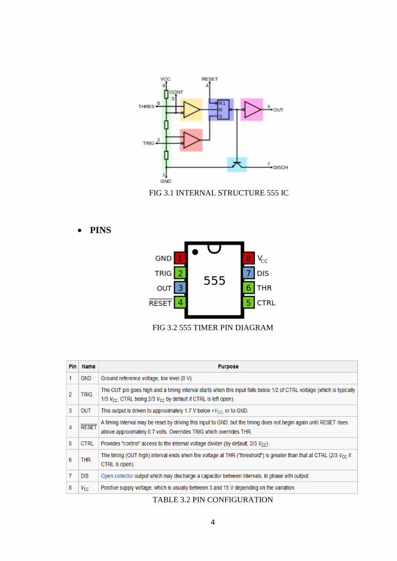
FIG 3.1 INTERNAL STRUCTURE 555 IC
PINS
FIG 3.2 555 TIMER PIN DIAGRAM
TABLE 3.2 PIN CONFIGURATION

5
MODES
The IC 555 has three operating modes:
Bistable mode or Schmitt trigger – the 555 can operate as a flip-flop, if the DIS pin is not
connected and no capacitor is used. Uses include bounce-free latched switches.
Monostable mode – in this mode, the 555 functions as a "one-shot" pulse generator.
Applications include timers, missing pulse detection, bounce free switches, touch switches,
frequency divider, capacitance measurement, pulse-width modulation (PWM) and so on.
Astable (free-running) mode – the 555 can operate as an electronic oscillator. Uses include
LED and lamp flashers, pulse generation, logic clocks, tone generation, security alarms,
pulse position modulation and so on. The 555 can be used as a simple ADC, converting an
analog value to a pulse length (e.g., selecting a thermistor as timing resistor allows the use
of the 555 in a temperature sensor and the period of the output pulse is determined by the
temperature). The use of a microprocessor-based circuit can then convert the pulse period to
temperature, linearize it and even provide calibration means.
BISTABLE
FIG 3.3 SCHEMATIC OF A 555 IN BISTABLE MODE
6
In bistable (also called Schmitt trigger) mode, the 555 timer acts as a basic flip-flop. The
trigger and reset inputs (pins 2 and 4 respectively on a 555) are held high via pull-up resistors
while the threshold input (pin 6) is simply floating. Thus configured, pulling the trigger
momentarily to ground acts as a 'set' and transitions the output pin (pin 3) to Vcc (high state).
Pulling the reset input to ground acts as a 'reset' and transitions the output pin to ground (low
state). No timing capacitors are required in a bistable configuration. Pin 5 (control voltage)
is connected to ground via a small-value capacitor (usually 0.01 to 0.1 μF). Pin 7 (discharge)
is left floating.
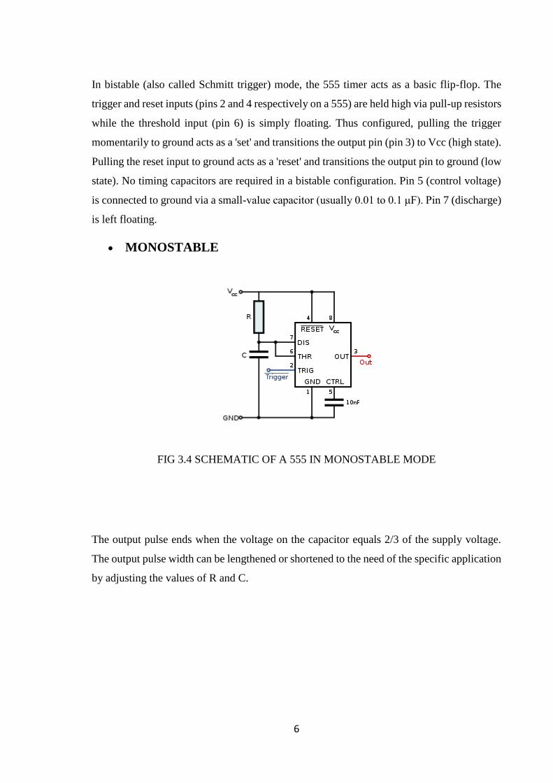
MONOSTABLE
FIG 3.4 SCHEMATIC OF A 555 IN MONOSTABLE MODE
The output pulse ends when the voltage on the capacitor equals 2/3 of the supply voltage.
The output pulse width can be lengthened or shortened to the need of the specific application
by adjusting the values of R and C.
7
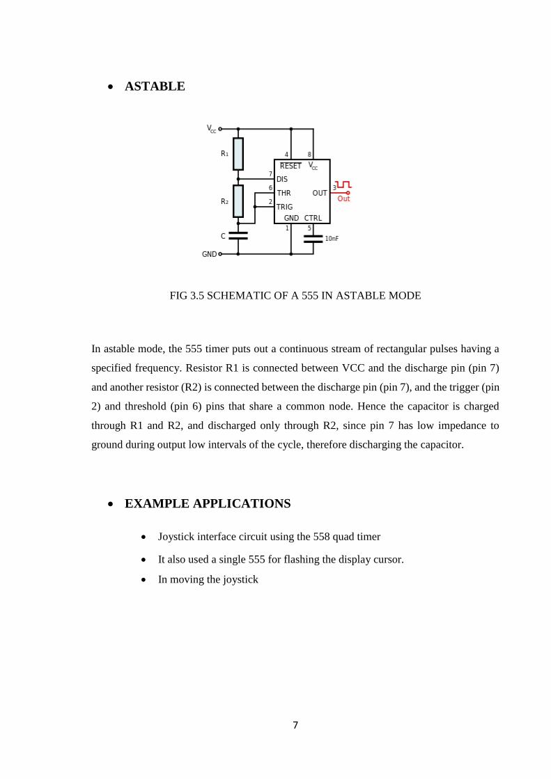
ASTABLE
FIG 3.5 SCHEMATIC OF A 555 IN ASTABLE MODE
In astable mode, the 555 timer puts out a continuous stream of rectangular pulses having a
specified frequency. Resistor R1 is connected between VCC and the discharge pin (pin 7)
and another resistor (R2) is connected between the discharge pin (pin 7), and the trigger (pin
2) and threshold (pin 6) pins that share a common node. Hence the capacitor is charged
through R1 and R2, and discharged only through R2, since pin 7 has low impedance to
ground during output low intervals of the cycle, therefore discharging the capacitor.
EXAMPLE APPLICATIONS
Joystick interface circuit using the 558 quad timer
It also used a single 555 for flashing the display cursor.
In moving the joystick
8
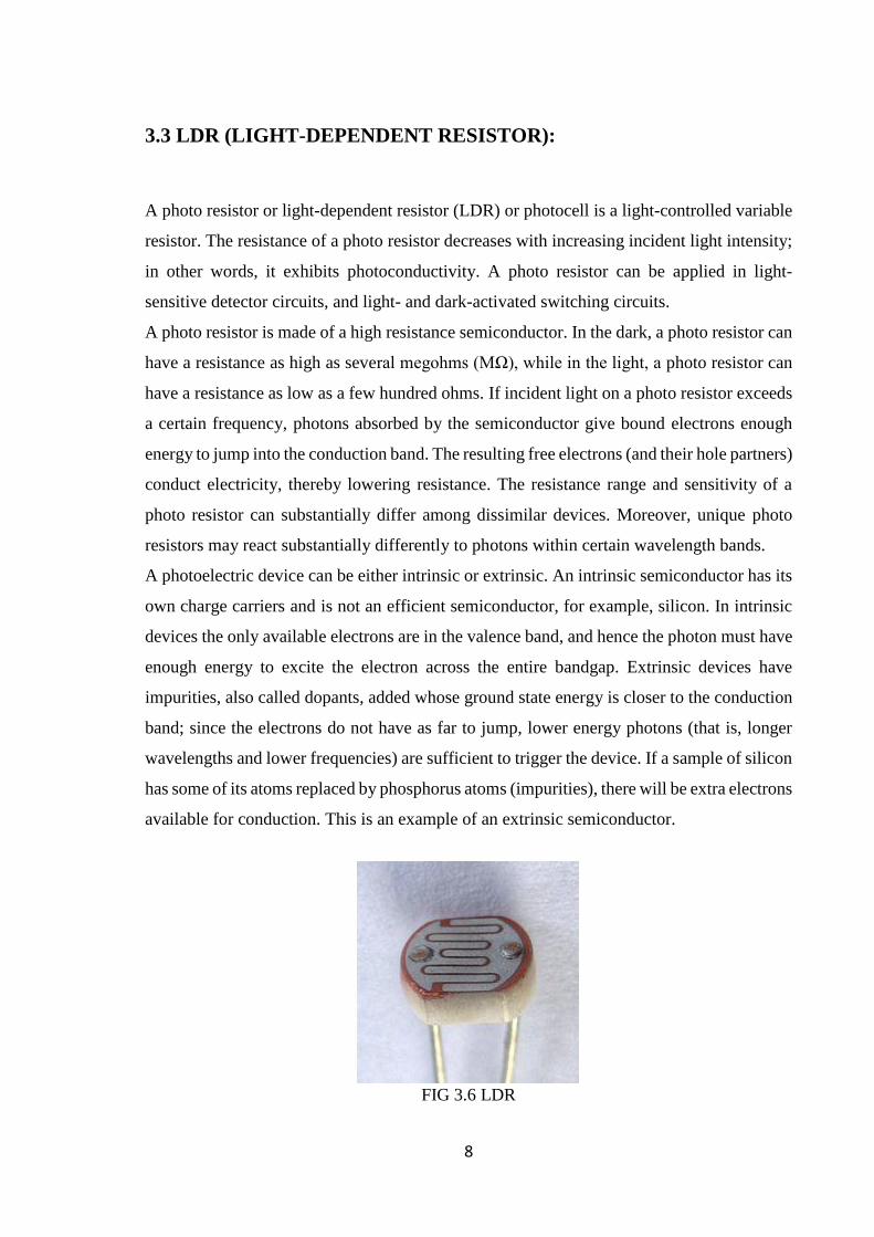
3.3 LDR (LIGHT-DEPENDENT RESISTOR):
A photo resistor or light-dependent resistor (LDR) or photocell is a light-controlled variable
resistor. The resistance of a photo resistor decreases with increasing incident light intensity;
in other words, it exhibits photoconductivity. A photo resistor can be applied in light-
sensitive detector circuits, and light- and dark-activated switching circuits.
A photo resistor is made of a high resistance semiconductor. In the dark, a photo resistor can
have a resistance as high as several megohms (MΩ), while in the light, a photo resistor can
have a resistance as low as a few hundred ohms. If incident light on a photo resistor exceeds
a certain frequency, photons absorbed by the semiconductor give bound electrons enough
energy to jump into the conduction band. The resulting free electrons (and their hole partners)
conduct electricity, thereby lowering resistance. The resistance range and sensitivity of a
photo resistor can substantially differ among dissimilar devices. Moreover, unique photo
resistors may react substantially differently to photons within certain wavelength bands.
A photoelectric device can be either intrinsic or extrinsic. An intrinsic semiconductor has its
own charge carriers and is not an efficient semiconductor, for example, silicon. In intrinsic
devices the only available electrons are in the valence band, and hence the photon must have
enough energy to excite the electron across the entire bandgap. Extrinsic devices have
impurities, also called dopants, added whose ground state energy is closer to the conduction
band; since the electrons do not have as far to jump, lower energy photons (that is, longer
wavelengths and lower frequencies) are sufficient to trigger the device. If a sample of silicon
has some of its atoms replaced by phosphorus atoms (impurities), there will be extra electrons
available for conduction. This is an example of an extrinsic semiconductor.
FIG 3.6 LDR
9
DESIGN CONSIDERATIONS
Photo resistors are less light-sensitive devices than photodiodes or phototransistors: the two
latter components are true semiconductor devices, while a photo resistor is a passive
component and does not have a PN-junction. The photoresistivity of any photo resistor may
vary widely depending on ambient temperature, making them unsuitable for applications
requiring precise measurement of or sensitivity to light.
Photo resistors also exhibit a certain degree of latency between exposure to light and the
subsequent decrease in resistance, usually around 10 milliseconds. The lag time when going
from lit to dark environments is even greater, often as long as one second. This property
makes them unsuitable for sensing rapidly flashing lights, but is sometimes used to smooth
the response of audio signal compression.
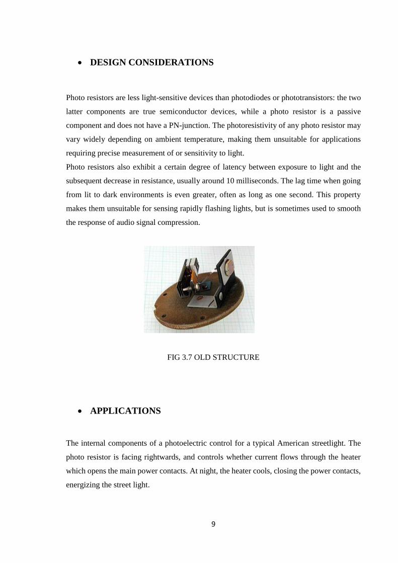
FIG 3.7 OLD STRUCTURE
APPLICATIONS
The internal components of a photoelectric control for a typical American streetlight. The
photo resistor is facing rightwards, and controls whether current flows through the heater
which opens the main power contacts. At night, the heater cools, closing the power contacts,
energizing the street light.
10
Photo resistors come in many types. Inexpensive cadmium sulphide cells can be found in
many consumer items such as camera light meters, clock radios, alarm devices (as the
detector for a light beam), night lights, outdoor clocks, solar street lamps and solar road studs,
etc.
Photo resistors can be placed in streetlights to control when the light is on. Ambient light
falling on the photo resistor causes the streetlight to turn off. Thus energy is saved by
ensuring the light is only on during hours of darkness.
They are also used in some dynamic compressors together with a small incandescent or neon
lamp, or light-emitting diode to control gain reduction. A common usage of this application
can be found in many guitar amplifiers that incorporate an onboard tremolo effect, as the
oscillating light patterns control the level of signal running through the amp circuit.
The use of CdS and CdSe photo resistors is severely restricted in Europe due to the RoHS
ban on cadmium.
Lead sulphide (PbS) and indium antimonide (InSb) LDRs (light-dependent resistors) are
used for the mid-infrared spectral region. Ge:Cu photoconductors are among the best far-
infrared detectors available, and are used for infrared astronomy and infrared spectroscopy.
11
3.4 LED (LIGHT-EMITTING DIODE):
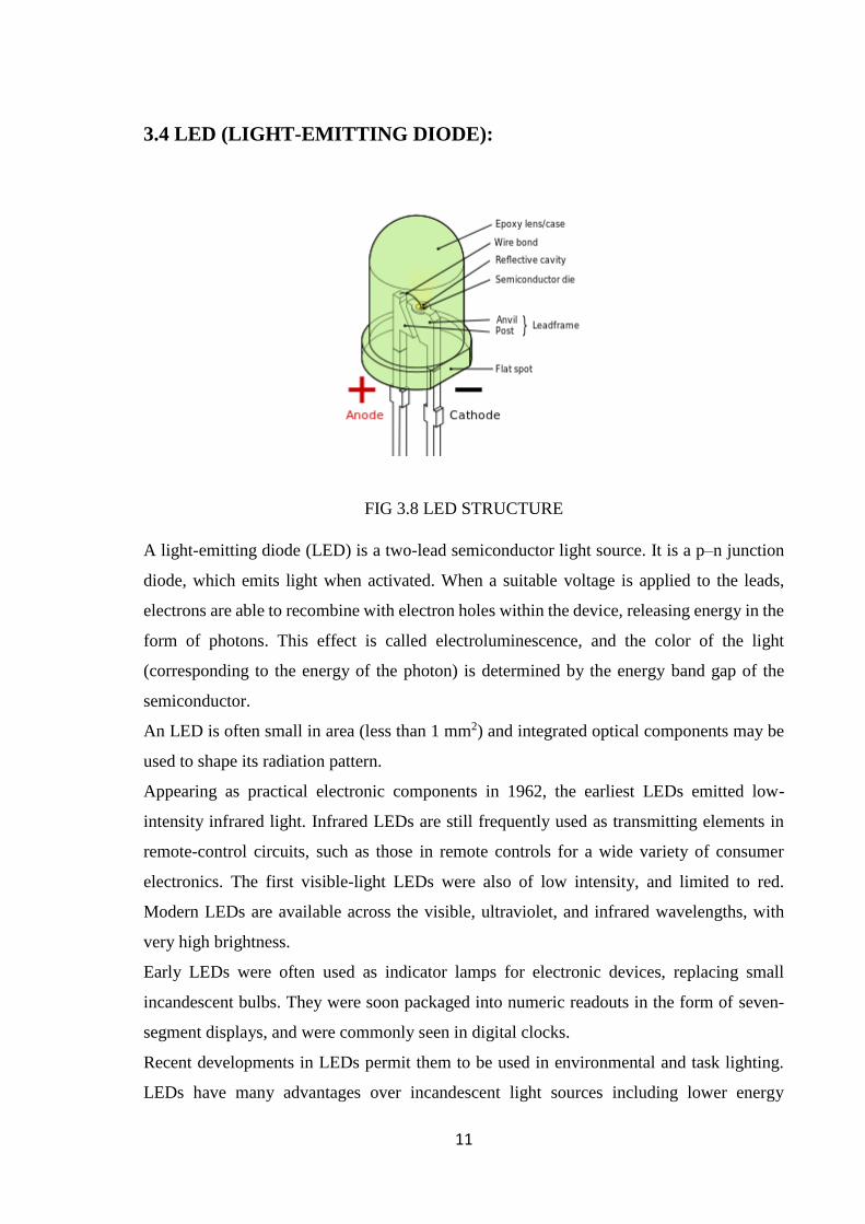
FIG 3.8 LED STRUCTURE
A light-emitting diode (LED) is a two-lead semiconductor light source. It is a p–n junction
diode, which emits light when activated. When a suitable voltage is applied to the leads,
electrons are able to recombine with electron holes within the device, releasing energy in the
form of photons. This effect is called electroluminescence, and the color of the light
(corresponding to the energy of the photon) is determined by the energy band gap of the
semiconductor.
An LED is often small in area (less than 1 mm2) and integrated optical components may be
used to shape its radiation pattern.
Appearing as practical electronic components in 1962, the earliest LEDs emitted low-
intensity infrared light. Infrared LEDs are still frequently used as transmitting elements in
remote-control circuits, such as those in remote controls for a wide variety of consumer
electronics. The first visible-light LEDs were also of low intensity, and limited to red.
Modern LEDs are available across the visible, ultraviolet, and infrared wavelengths, with
very high brightness.
Early LEDs were often used as indicator lamps for electronic devices, replacing small
incandescent bulbs. They were soon packaged into numeric readouts in the form of seven-
segment displays, and were commonly seen in digital clocks.
Recent developments in LEDs permit them to be used in environmental and task lighting.
LEDs have many advantages over incandescent light sources including lower energy
12
consumption, longer lifetime, improved physical robustness, smaller size, and faster
switching. Light-emitting diodes are now used in applications as diverse as aviation lighting,
automotive headlamps, advertising, general lighting, traffic signals, camera flashes and even
LED wallpaper. As of 2015, LEDs powerful enough for room lighting remain somewhat
more expensive, and require more precise current and heat management, than compact
fluorescent lamp sources of comparable output.
WORKING PRINCIPLE
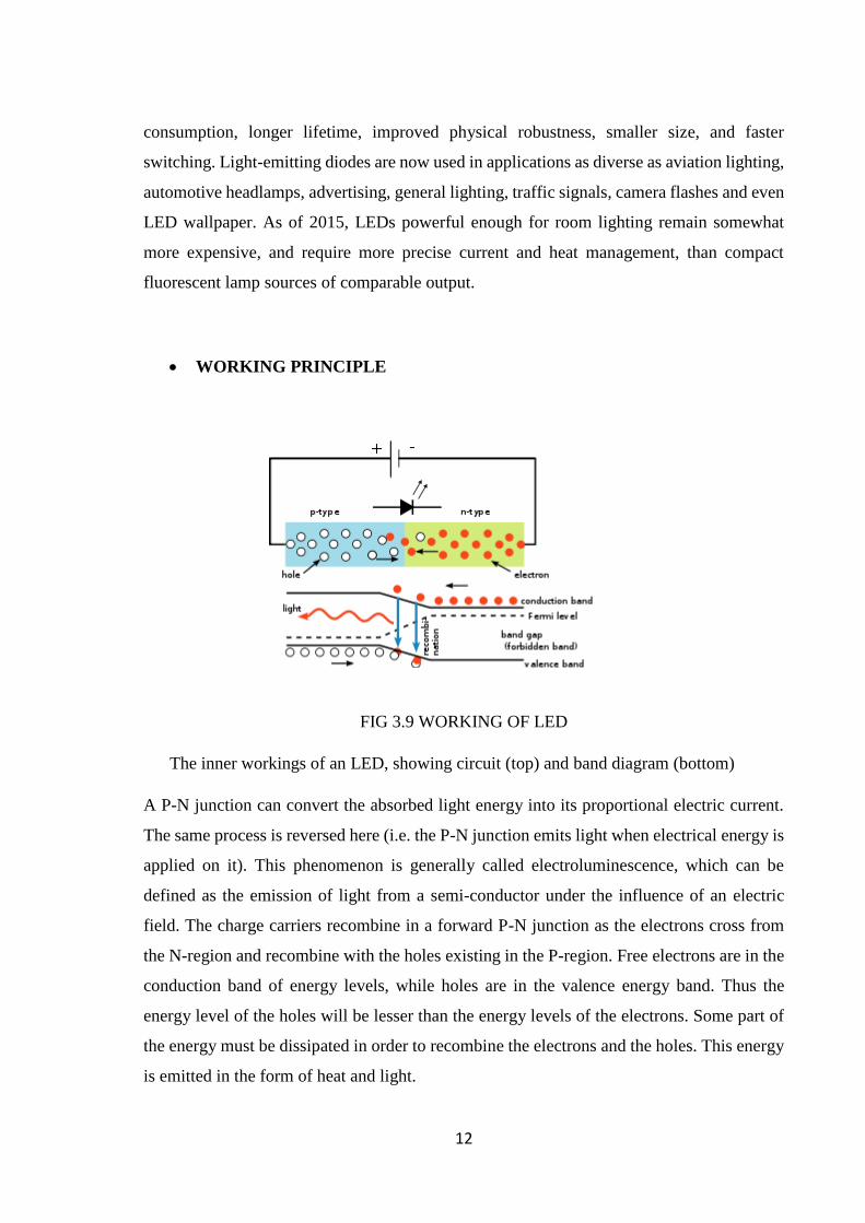
FIG 3.9 WORKING OF LED
The inner workings of an LED, showing circuit (top) and band diagram (bottom)
A P-N junction can convert the absorbed light energy into its proportional electric current.
The same process is reversed here (i.e. the P-N junction emits light when electrical energy is
applied on it). This phenomenon is generally called electroluminescence, which can be
defined as the emission of light from a semi-conductor under the influence of an electric
field. The charge carriers recombine in a forward P-N junction as the electrons cross from
the N-region and recombine with the holes existing in the P-region. Free electrons are in the
conduction band of energy levels, while holes are in the valence energy band. Thus the
energy level of the holes will be lesser than the energy levels of the electrons. Some part of
the energy must be dissipated in order to recombine the electrons and the holes. This energy
is emitted in the form of heat and light.

13
The electrons dissipate energy in the form of heat for silicon and germanium diodes but in
gallium arsenide phosphide (GaAsP) and gallium phosphide (GaP) semiconductors, the
electrons dissipate energy by emitting photons. If the semiconductor is translucent, the
junction becomes the source of light as it is emitted, thus becoming a light-emitting diode,
but when the junction is reverse biased no light will be produced by the LED and, on the
contrary, the device may also get damaged.
White LED
There are two primary ways of producing white light-emitting diodes (WLEDs), LEDs that
generate high-intensity white light. One is to use individual LEDs that emit three primary
colors[91]—red, green, and blue—and then mix all the colors to form white light. The other
is to use a phosphor material to convert monochromatic light from a blue or UV LED to
broad-spectrum white light, much in the same way a fluorescent light bulb works.
There are three main methods of mixing colors to produce white light from an LED:
blue LED + green LED + red LED (color mixing; can be used as backlighting for
displays)
near-UV or UV LED + RGB phosphor (an LED producing light with a wavelength
shorter than blue's is used to excite an RGB phosphor)
blue LED + yellow phosphor (two complementary colors combine to form white
light; more efficient than first two methods and more commonly used)[92]
FIG 3.10 WHITE LED
14
3.5 CAPACITOR:
A capacitor (originally known as a condenser) is a passive two-terminal electrical component
used to store electrical energy temporarily in an electric field. The forms of practical
capacitors vary widely, but all contain at least two electrical conductors (plates) separated by
a dielectric (i.e. an insulator that can store energy by becoming polarized). The conductors
can be thin films, foils or sintered beads of metal or conductive electrolyte, etc. The non -
conducting dielectric acts to increase the capacitor's charge capacity. A dielectric can be
glass, ceramic, plastic film, air, vacuum, paper, mica, oxide layer etc. Capacitors are widely
used as parts of electrical circuits in many common electrical devices. Unlike a resistor, an
ideal capacitor does not dissipate energy. Instead, a capacitor stores energy in the form of an
electrostatic field between its plates.
When there is a potential difference across the conductors (e.g., when a capacitor is attached
across a battery), an electric field develops across the dielectric, causing positive charge +Q
to collect on one plate and negative charge −Q to collect on the other plate. If a battery has
been attached to a capacitor for a sufficient amount of time, no current can flow through the
capacitor. However, if a time-varying voltage is applied across the leads of the capacitor, a
displacement current can flow.
An ideal capacitor is characterized by a single constant value, its capacitance. Capacitance
is defined as the ratio of the electric charge Q on each conductor to the potential difference
V between them. The SI unit of capacitance is the farad (F), which is equal to one coulomb
per volt (1 C/V). Typical capacitance values range from about 1 pF (10−12 F) to about 1 mF
(10−3 F).
The larger the surface area of the "plates" (conductors) and the narrower the gap between
them, the greater the capacitance is. In practice, the dielectric between the plates passes a
small amount of leakage current and also has an electric field strength limit, known as the
breakdown voltage. The conductors and leads introduce an undesired inductance and
resistance.
Capacitors are widely used in electronic circuits for blocking direct current while allowing
alternating current to pass. In analog filter networks, they smooth the output of power
supplies. In resonant circuits they tune radios to particular frequencies. In electric power
transmission systems, they stabilize voltage and power flow.
15
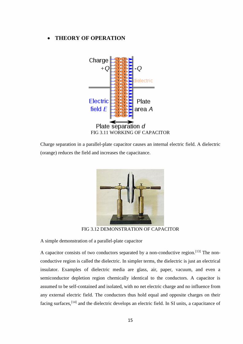
THEORY OF OPERATION
FIG 3.11 WORKING OF CAPACITOR
Charge separation in a parallel-plate capacitor causes an internal electric field. A dielectric
(orange) reduces the field and increases the capacitance.
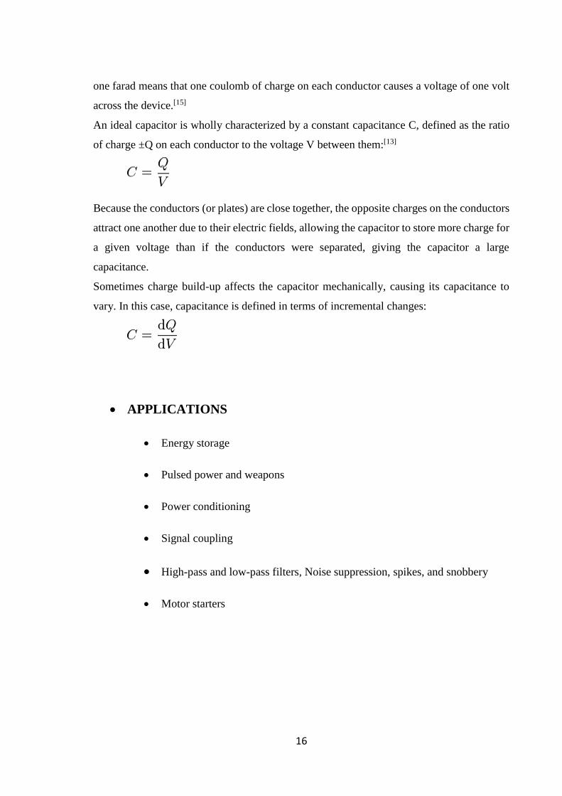
FIG 3.12 DEMONSTRATION OF CAPACITOR
A simple demonstration of a parallel-plate capacitor
A capacitor consists of two conductors separated by a non-conductive region.[13] The non-
conductive region is called the dielectric. In simpler terms, the dielectric is just an electrical
insulator. Examples of dielectric media are glass, air, paper, vacuum, and even a
semiconductor depletion region chemically identical to the conductors. A capacitor is
assumed to be self-contained and isolated, with no net electric charge and no influence from
any external electric field. The conductors thus hold equal and opposite charges on their
facing surfaces,[14] and the dielectric develops an electric field. In SI units, a capacitance of
16
one farad means that one coulomb of charge on each conductor causes a voltage of one volt
across the device.[15]
An ideal capacitor is wholly characterized by a constant capacitance C, defined as the ratio
of charge ±Q on each conductor to the voltage V between them:[13]
Because the conductors (or plates) are close together, the opposite charges on the conductors
attract one another due to their electric fields, allowing the capacitor to store more charge for
a given voltage than if the conductors were separated, giving the capacitor a large
capacitance.
Sometimes charge build-up affects the capacitor mechanically, causing its capacitance to
vary. In this case, capacitance is defined in terms of incremental changes:
APPLICATIONS
Energy storage
Pulsed power and weapons
Power conditioning
Signal coupling
High-pass and low-pass filters, Noise suppression, spikes, and snobbery
Motor starters
17
3.6 RESISTOR:
A resistor is a passive two-terminal electrical component that implements electrical
resistance as a circuit element. Resistors act to reduce current flow, and, at the same time,
act to lower voltage levels within circuits. In electronic circuits, resistors are used to limit
current flow, to adjust signal levels, bias active elements, and terminate transmission lines
among other uses. High-power resistors, that can dissipate many watts of electrical power as
heat, may be used as part of motor controls, in power distribution systems, or as test loads
for generators. Fixed resistors have resistances that only change slightly with temperature,
time or operating voltage. Variable resistors can be used to adjust circuit elements (such as
a volume control or a lamp dimmer), or as sensing devices for heat, light, humidity, force, or
chemical activity.
Resistors are common elements of electrical networks and electronic circuits and are
ubiquitous in electronic equipment. Practical resistors as discrete components can be
composed of various compounds and forms. Resistors are also implemented within
integrated circuits.
The electrical function of a resistor is specified by its resistance: common commercial
resistors are manufactured over a range of more than nine orders of magnitude. The nominal
value of the resistance will fall within a manufacturing tolerance.
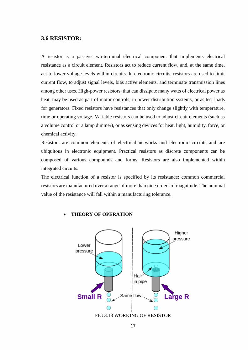
THEORY OF OPERATION
FIG 3.13 WORKING OF RESISTOR
18
The hydraulic analogy compares electric current flowing through circuits to water flowing
through pipes. When a pipe (left) is filled with hair (right), it takes a larger pressure to achieve
the same flow of water. Pushing electric current through a large resistance is like pushing
water through a pipe clogged with hair: It requires a larger push (voltage drop) to drive the
same flow (electric current).
OHM’S LAW
The behavior of an ideal resistor is dictated by the relationship specified by Ohm's law:
Ohm's law states that the voltage (V) across a resistor is proportional to the current (I), where
the constant of proportionality is the resistance (R). For example, if a 300 ohm resistor is
attached across the terminals of a 12 volt battery, then a current of 12 / 300 = 0.04 amperes
flows through that resistor.
Practical resistors also have some inductance and capacitance which will also affect the
relation between voltage and current in alternating current circuits.
The ohm (symbol: Ω) is the SI unit of electrical resistance, named after Georg Simon Ohm.
An ohm is equivalent to a volt per ampere. Since resistors are specified and manufactured
over a very large range of values, the derived units of milliohm (1 mΩ = 10−3 Ω), kilohm (1
kΩ = 103 Ω), and megohm (1 MΩ = 106 Ω) are also in common usage.

19
CHAPTER 4
CIRCUIT
4.1 DIAGRAM:
FIG 4.1 CIRCUIT DIAGRAM
Circuit consist of a NE555 Timer IC whose PIN 8 is connected to VCC and PIN 1 and 6 is
connected to GND. LDR is connected in between PIN 4 and PIN 1 with parallel to 100K
Resistance connected to PIN 8. A 1nF Capacitor is connected between PIN 2 and PIN 1.
1M ohm Resistance is in between PIN 6 and PIN 3 while PIN 5 and PIN 7 do not require
any attachment for this circuit implementation. 4 white- LED are connected in parallel in
between PIN 3 and PIN 1. For testing purpose RED- LED is used for easier debugging and
testing of the circuit implementation.
VCC is connected to the positive terminal of the 9V DC Battery and GND is connected to
the negative terminal of the battery. It can be made as in the switch ON/OFF circuit by
adding a push button as per the requirement.
20
4.2 WORKING PHASE 1:
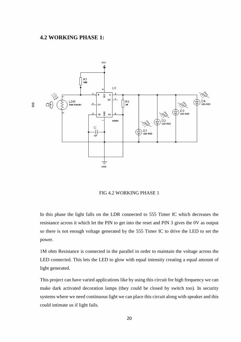
FIG 4.2 WORKING PHASE 1
In this phase the light falls on the LDR connected to 555 Timer IC which decreases the
resistance across it which let the PIN to get into the reset and PIN 3 gives the 0V as output
so there is not enough voltage generated by the 555 Timer IC to drive the LED to set the
power.
1M ohm Resistance is connected in the parallel in order to maintain the voltage across the
LED connected. This lets the LED to glow with equal intensity creating a equal amount of
light generated.
This project can have varied applications like by using this circuit for high frequency we can
make dark activated decoration lamps (they could be closed by switch too). In security
systems where we need continuous light we can place this circuit along with speaker and this
could intimate us if light fails.
21
4.2 WORKING PHASE 2:
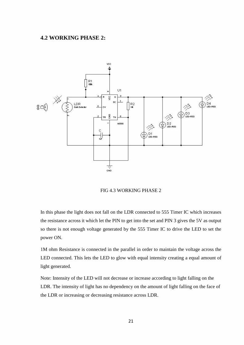
FIG 4.3 WORKING PHASE 2
In this phase the light does not fall on the LDR connected to 555 Timer IC which increases
the resistance across it which let the PIN to get into the set and PIN 3 gives the 5V as output
so there is not enough voltage generated by the 555 Timer IC to drive the LED to set the
power ON.
1M ohm Resistance is connected in the parallel in order to maintain the voltage across the
LED connected. This lets the LED to glow with equal intensity creating a equal amount of
light generated.
Note: Intensity of the LED will not decrease or increase according to light falling on the
LDR. The intensity of light has no dependency on the amount of light falling on the face of
the LDR or increasing or decreasing resistance across LDR.
22
CHAPTER 5
SIMULATION
5.1 PROTEUS
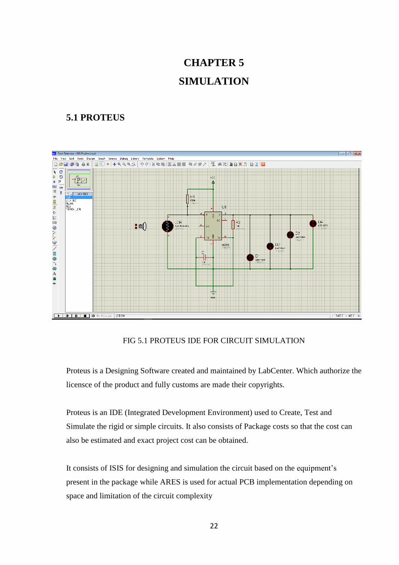
FIG 5.1 PROTEUS IDE FOR CIRCUIT SIMULATION
Proteus is a Designing Software created and maintained by LabCenter. Which authorize the
licensce of the product and fully customs are made their copyrights.
Proteus is an IDE (Integrated Development Environment) used to Create, Test and
Simulate the rigid or simple circuits. It also consists of Package costs so that the cost can
also be estimated and exact project cost can be obtained.
It consists of ISIS for designing and simulation the circuit based on the equipment’s
present in the package while ARES is used for actual PCB implementation depending on
space and limitation of the circuit complexity
23
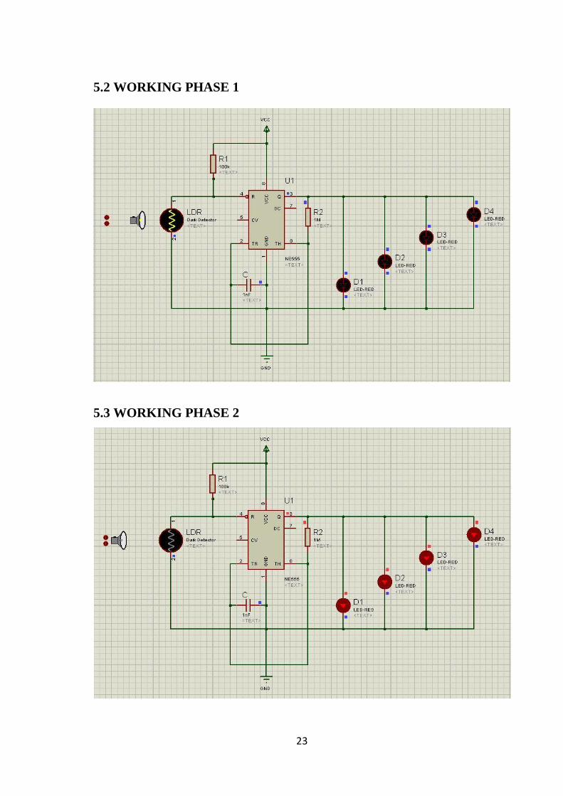
5.2 WORKING PHASE 1
5.3 WORKING PHASE 2
24
CHAPTER 6
COMPLETED HARDWARE
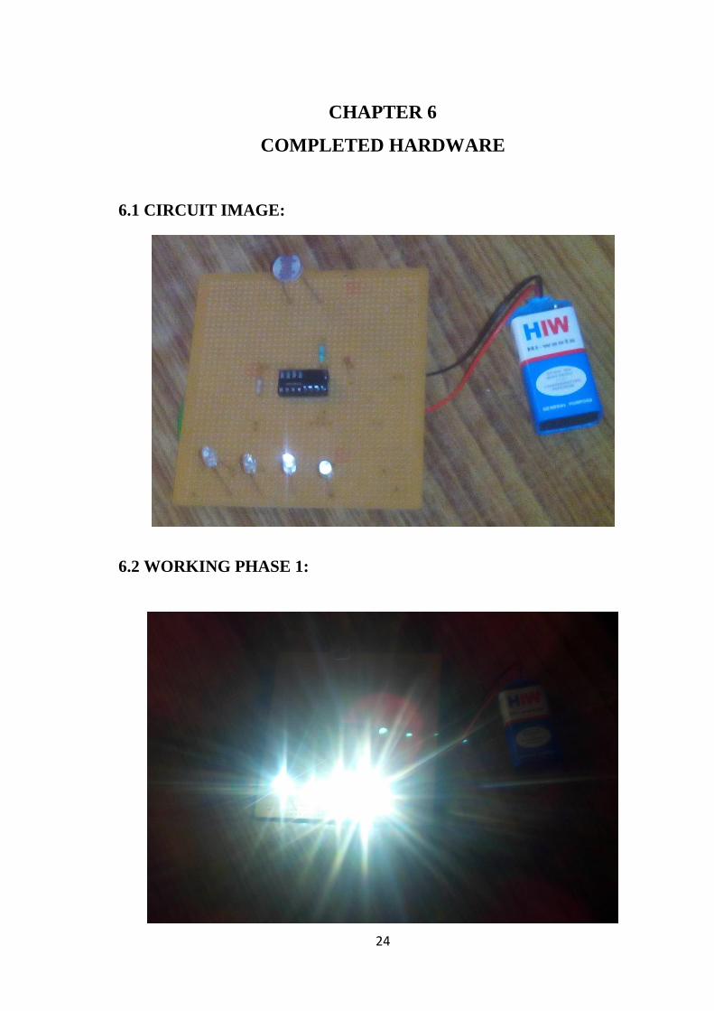
6.1 CIRCUIT IMAGE:
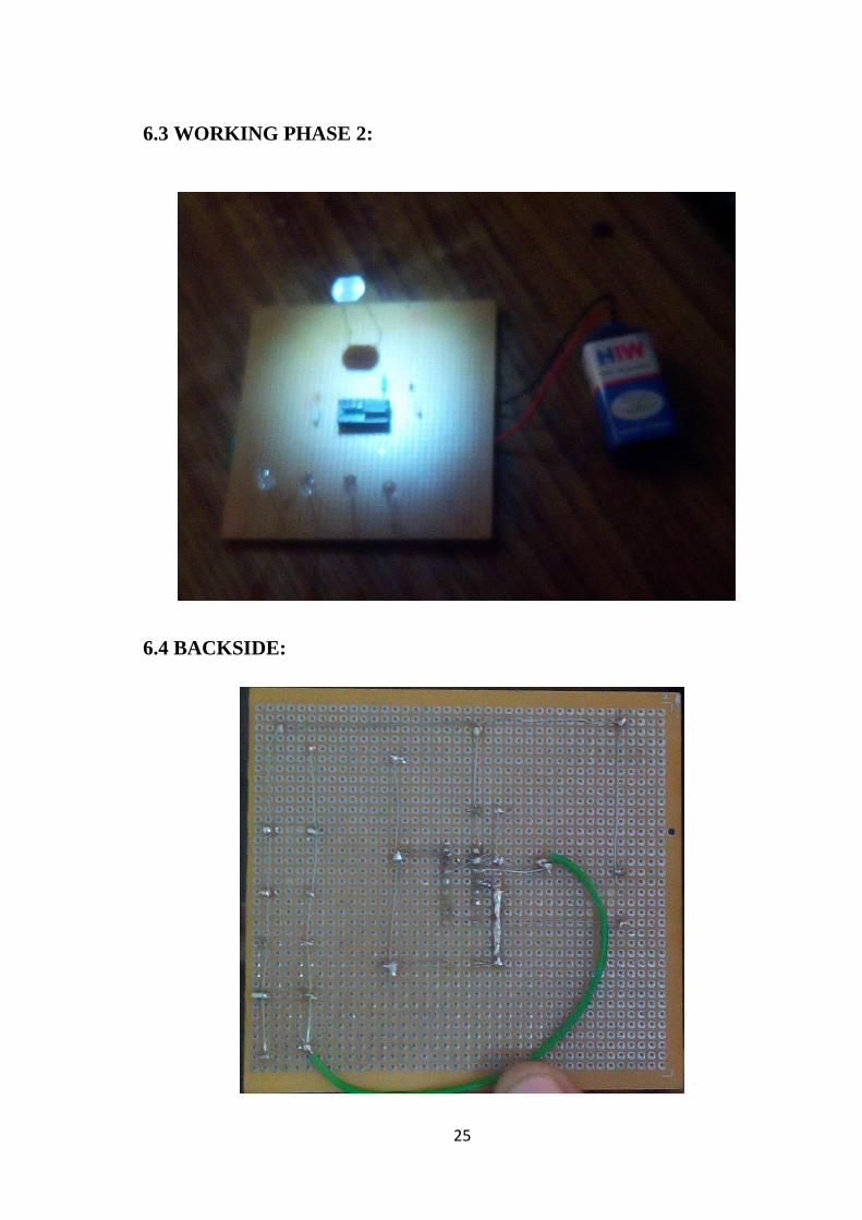
6.2 WORKING PHASE 1:
25
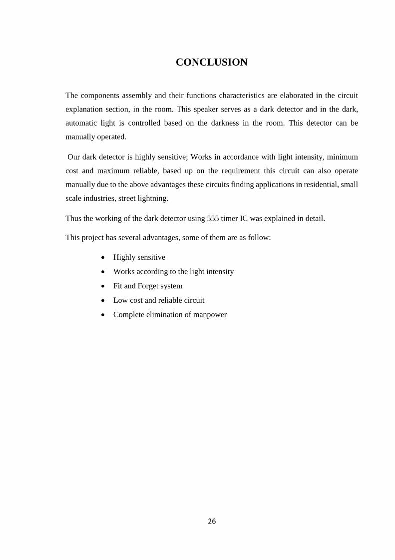
6.3 WORKING PHASE 2:
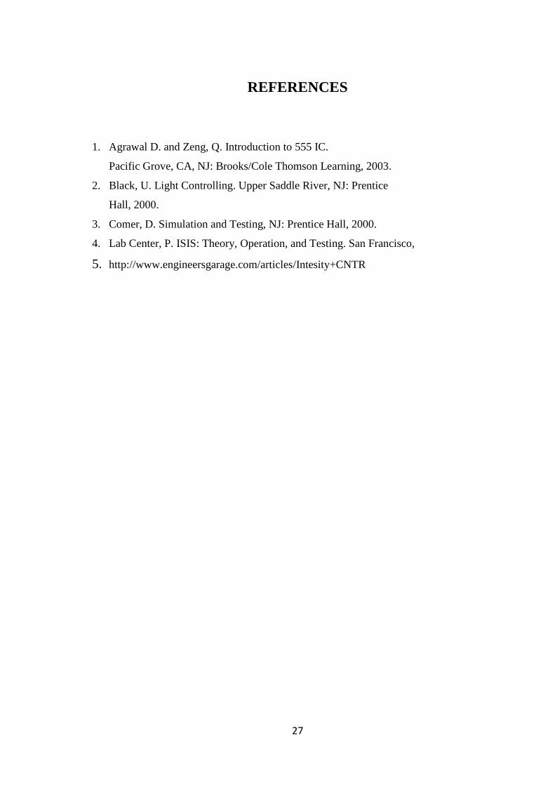
6.4 BACKSIDE:
26
CONCLUSION
The components assembly and their functions characteristics are elaborated in the circuit
explanation section, in the room. This speaker serves as a dark detector and in the dark,
automatic light is controlled based on the darkness in the room. This detector can be
manually operated.
Our dark detector is highly sensitive; Works in accordance with light intensity, minimum
cost and maximum reliable, based up on the requirement this circuit can also operate
manually due to the above advantages these circuits finding applications in residential, small
scale industries, street lightning.
Thus the working of the dark detector using 555 timer IC was explained in detail.
This project has several advantages, some of them are as follow:
Highly sensitive
Works according to the light intensity
Fit and Forget system
Low cost and reliable circuit
Complete elimination of manpower
27
REFERENCES
1. Agrawal D. and Zeng, Q. Introduction to 555 IC.
Pacific Grove, CA, NJ: Brooks/Cole Thomson Learning, 2003.
2. Black, U. Light Controlling. Upper Saddle River, NJ: Prentice
Hall, 2000.
3. Comer, D. Simulation and Testing, NJ: Prentice Hall, 2000.
4. Lab Center, P. ISIS: Theory, Operation, and Testing. San Francisco,
5. http://www.engineersgarage.com/articles/Intesity+CNTR