das program - staging.power-solutions.com
TRANSCRIPT

DAS ProgramProduct Selection Guide
© 2013 General Electric Company. All rights reserved.ATT Outside Plant Argent Catalog06/13

DAS Program Guide | GECriticalPower.com2
Solutions Included in the GuideThe DAS Program selection guide has been created for ease of access to the primary products utilized by telecom providers on a daily basis. For products not featured in the guide, please contact a GE representative.
Power Express Class 2 Distribution
DC-DC Up-Converter
Slimline Power System (SPS)
Micro-BDFB / SPDU
5067 Mini-BDFB
Infinity M Power System
Infinity S Power System
RBA72 Power & Battery Cabinets
GPS4827 Power System
DAS Program Guide | GECriticalPower.com 3
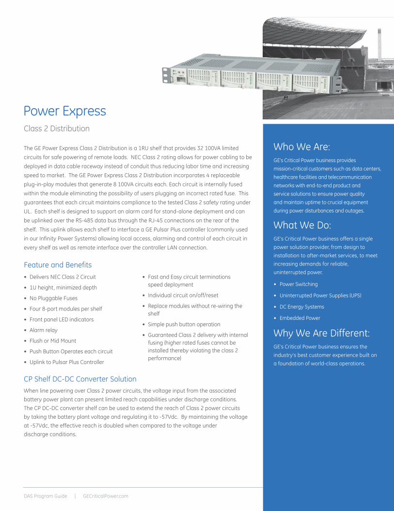
The GE Power Express Class 2 Distribution is a 1RU shelf that provides 32 100VA limited circuits for safe powering of remote loads. NEC Class 2 rating allows for power cabling to be deployed in data cable raceway instead of conduit thus reducing labor time and increasing speed to market. The GE Power Express Class 2 Distribution incorporates 4 replaceable plug-in-play modules that generate 8 100VA circuits each. Each circuit is internally fused within the module eliminating the possibility of users plugging an incorrect rated fuse. This guarantees that each circuit maintains compliance to the tested Class 2 safety rating under UL. Each shelf is designed to support an alarm card for stand-alone deployment and can be uplinked over the RS-485 data bus through the RJ-45 connections on the rear of the shelf. This uplink allows each shelf to interface a GE Pulsar Plus controller (commonly used in our Infinity Power Systems) allowing local access, alarming and control of each circuit in every shelf as well as remote interface over the controller LAN connection.
• Delivers NEC Class 2 Circuit
• 1U height, minimized depth
• No Pluggable Fuses
• Four 8-port modules per shelf
• Front panel LED indicators
• Alarm relay
• Flush or Mid Mount
• Push Button Operates each circuit
• Uplink to Pulsar Plus Controller
• Fast and Easy circuit terminations speed deployment
• Individual circuit on/off/reset
• Replace modules without re-wiring the shelf
• Simple push button operation
• Guaranteed Class 2 delivery with internal fusing (higher rated fuses cannot be installed thereby violating the class 2 performance)
Feature and Benefits
CP Shelf DC-DC Converter SolutionWhen line powering over Class 2 power circuits, the voltage input from the associated battery power plant can present limited reach capabilities under discharge conditions. The CP DC-DC converter shelf can be used to extend the reach of Class 2 power circuits by taking the battery plant voltage and regulating it to -57Vdc. By maintaining the voltage at -57Vdc, the effective reach is doubled when compared to the voltage under discharge conditions.
Power ExpressClass 2 Distribution
Who We Are:GE’s Critical Power business provides mission-critical customers such as data centers, healthcare facilities and telecommunication networks with end-to-end product and service solutions to ensure power quality and maintain uptime to crucial equipment during power disturbances and outages.
What We Do: GE’s Critical Power business offers a single power solution provider, from design to installation to after-market services, to meet increasing demands for reliable, uninterrupted power.
• Power Switching
• Uninterrupted Power Supplies (UPS)
• DC Energy Systems
• Embedded Power
Why We Are Different: GE’s Critical Power business ensures the industry’s best customer experience built on a foundation of world-class operations.
DAS Program Guide | GECriticalPower.com4
Ordering Information
Safety and Standards ComplianceNEBs Evaluation by independent NRTL test lab to Telcordia GR63, Issue
4 & GR 1089, Issue 6Safety UL 60950-1, Recognized
CSA C22.2 No. 60950-1-04RoHS Compliant to RoHS EU Directive 2002/95/ECEMC FCC-CFR, Part 15, sub-part B Class B with shelf; GR1089 Class AESD EN61000-4-2, Level 4
Safety and Standards ComplianceZone 4 Per Telcordia GR-63-CORE, all floors when installed in CPL shelf Safety CE mark to Low Voltage Directive 2006/95/EC
UL 609501-1 Recognized CAN/CSA C22.2 No. 60950-1-04 Certified VDE 0805-1 Licensed to IEC60950-1
RoHS Compliant to RoHS EU Directive 2002/95/EC EMC FCC and CISPR22 (EN 55022) Class A ESD EN/IEC 61000-4-2 Level 3
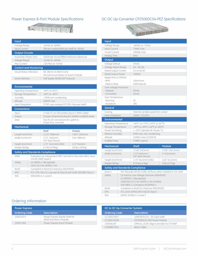
Power Express 8-Port Module Specifications DC-DC Up-Converter CP2500DC54-PEZ Specifications
InputVoltage Range -42Vdc to -60VdcInput Current 20A per module (80A per shelf) at -40Vdc
Output CircuitsAutomatic Power Limit 100VA per circuit (98VA minimum tolerance)Voltage Range -42Vdc to -60VdcMax Current 2.38 Max at -42Vdc
Control and MonitoringVisual Status Indicators OK, Alarm on Alarm Card
OK and Circuit Status on 8 port ModuleSerial Interface Half duplex RS485 (GP Protocol)
InputVoltage Range -40Vdc to -72VdcInput Current 75Adc maxInrush Current 100Adc maxHoldup Time 6ms
OutputVoltage Default 54VdcVoltage Adjust Range 44 - 58 VdcRated Output Current 0.1 to 46.3ARated Output Power 2500WRipple (5Hz to 20MHz)-RMS-Peak to Peak
250mVrms500mVpk-pk
Over Voltage Protection-Delayed-Immediate
60Vdc65Vdc
Over Temperature-Warning-Shutdown
5C20C
GeneralCooling Internal variable speed fan cooled Heat Dissipation 220W / 751 BTU
EnvironmentalOperating Temperature -40ºC1 to +75ºC (-40°F to 167°F) Storage Temperature -40°C to +85°C (-40°F to 185°F) Power De-Rating > +55°C (derates @ 2% per °C) Relative Humidity 95% max, non-condensing Altitude 4,000m max (13,000 ft) Audible Noise 55dBA, typical
EnvironmentalOperating Temperature -40°C to +65°CStorage Temperature -40°C to +85°C Humidity < 95% non-condensingAltitude 4000M max Heat Dissipation 57 BTU per module (227 BTU Max per shelf)
Power Express
Ordering Code Description150031971 Power Express Starter Shelf Kit
(Shelf and Alarm Module) 150027362 Power Express 8 port Module
DC to DC Up-Converter System
Ordering Code DescriptionCC109157657 J2007001L014 - DC input shelfCC109170528 CP2500DC54-PEZ Power Module150036109 CP841A_3C3R, Edge Controller for CP ShelfCC848817651 Alarm Cable
ConnectionsInput 2-hole ¼” on 5/8 centers (Up to 2 AWG Cable)Output 32 pairs of terminal strip for 24AWG to 8AWG wiresData Two RJ-45 connections for uplink to
Pulsar Plus controllerAlarm Three terminal alarm wire (NO, Common, NC) Mechanical
Shelf ModuleLength (inch/mm) 11.25” (286mm) 7.625” (194mm)Width (inch/mm) 17.5” (445mm)
(19” Rack Mount)3.44” (88mm)
Height (inch/mm) 1.75” (44.5mm) (1RU) 1.72” (44mm)Weight (lb/Kg) 6.5 lbs (2.95kg) 0.8 lbs (.363kg) Mechanical Shelf Module
Length (inch/mm) 17.06” (433mm) 13.85” (351.2mm) Width (inch/mm) 17.5” (445mm )
(19” Rack Mount) 4” (101.6mm)
Height (inch/mm) 1.75” (44.5mm) (1RU) 1.63” (41.4mm) Weight (lb/Kg) 8.75 lbs (4.0kg) 5 lbs (2.27kg)

DAS Program Guide | GECriticalPower.com 5
Shelf OptionsThe Slimline Power System product line provides several shelf options equipped with Ethernet, alarm inputs/outputs, and 1-Wire* connection for battery voltage and temperature monitoring. The rectifier-only shelf holds up to three 1600 Watt rectifier modules. Shelves can be deployed in parallel to increase output capacity. Other shelf configurations hold up to two 1000 Watt rectifier modules and include an integrated distribution module with circuit breakers, GMT fuse positions, and low-voltage battery disconnect circuit.
SPS TE Rectifier This hardened rectifier is a single phase, hot pluggable, fan cooled rectifier that provides up to 1600 Watts of high availability DC power. The constant output power characteristics, extended temperature range, universal AC input, and compact size are key attributes that make this rectifier the right choice for your power needs.
Pulsar Edge Controller SPS features the Pulsar Edge controller delivering large system intelligence in a small system form factor. Ethernet connectivity with SNMP facilitates remote network management.
Feature and Benefits• Customer premise power for
converged networks
• Large plant features in a small plant package
• 3000 Watts / 60 Amps single shelf capacity in 1RU
• 10.3 inches (264mm) depth is ideal where space is restricted
• 95% Efficiency
The Slimline Power System provides advanced controller features in a compact, cost-efficient footprint. The SPS shelf is 1.75” high, 10.3” deep and mounts in 19-inch or 23-inch wide frames, with three power slots for rectifiers and distribution. The Pulsar Edge controller has Ethernet connectivity to facilitate remote network management to monitor and control rectifiers, batteries, and distribution. SPS is a reliable DC power solution where system height and depth are restricted.
Slimline Power System48V DC Outside Plant and Customer Premise Solution

DAS Program Guide | GECriticalPower.com6
SPS TE Rectifiers
Applications
Key Features
The SPS TE rectifiers are single phase, hot-pluggable, fan cooled rectifiers that provide highly reliable DC power. As cost-effective rectifiers that occupy just 1RU, its shallow depth is an ideal power solution for space critical applications. The constant output power characteristics as well as the extended temperature range, universal AC input voltage range and compact size are key attributes that make this rectifier the right choice for your power needs.
These rectifiers are applicable for indoor and outdoor environments especially where equipment depth and height are restricted. The SPS TE rectifiers communicate digitally to the Pulsar Edge controller family over a RS485 bus to add extensive monitoring and alarm management facilities. Its flexible and sophisticated feature set makes this front-end supply an excellent choice for power in a variety of application spaces.
• Telecommunications networks
• Digital subscriber line (DSL)
• Indoor/outdoor wireless
• Routers/switches
• Fiber in the loop
• Transmission
• Data networks
• PBX
• Extended temperature range
• Redundant fan cooling
• Front panel LED indicators
• 1U height, minimized depth
• Universal AC input
• Analog load sharing
• Hot pluggable
• RoHS compliant
Input EP0500UTEZ EP1000UTEZ EP1600UTEZ
Voltage Range - Low-Line - High-Line
90-175Vac (500W)176-264Vac (500W)
90-175Vac (1000W)176-264Vac (1000W)
90-175Vac (1200W)176-264Vac (1600W)
Input Current 6.25-4.5A @ 90-120Vac2.55A @ 230Vac
12.5-9.3A @ 90-120Vac5.1A @ 230Vac
15-12A @ 90-120Vac7.5A @ 230Vac
Input Frequency 45 – 65Hz 45 – 65Hz 45 – 65Hz
Inrush Transient 25 Apk 25 Apk 25 Apk
Power Factor ~1.0 ~1.0 ~1.0
Efficiency 95% 95% 95%
Total Harmonic Distortion <5% <5% <5%
Holdup Time >10 ms full power >10 ms full power >10 ms full power
Output
Voltage Adjust Range 42-58Vdc 42-58Vdc 42-58Vdc
Voltage Nominal 54.5V 54.5V 54.5V
Rated Output Current - Low Line - High Line
10Adc max 10Adc max
20Adc max 20Adc max
24Adc max 32Adc max
Rated Output Power - Low Line - High Line
500 Watts (10A) 500 Watts (10A)
1000 Watts (20A) 1000 Watts (20A)
1200 Watts (24A) 1600 Watts (32A)
Psophometric Noise <5 mV max <5 mV max <5 mV max
Ripple <200 mVpkpk <200 mVpkpk <200 mVpkpk
Overvoltage Protection 59.5Vdc 59.5Vdc 59.5Vdc
Control and Monitoring
Visual Status Indicators Run, Alarm and Fault LEDs
Serial Interface Half duplex RS485 (GP Protocol)
DAS Program Guide | GECriticalPower.com 7
Environmental
Operating Temperature -40°C to +75°C (-40°F to 167°F)
Storage Temperature -40°C to +85°C (-40°F to 185°F)
Power Derating > +50°C 2% per degree Celcius
Humidity < 95% non-condensing
Altitude 4000M max
Audible Noise < 55dBA
Safety and Standards Compliance
NEBs Evaluated by independent NRTL test lab to Telcordia GR63, Issue 4 & GR 1089, Issue 6
Safety CE mark to Low Voltage Directive 2006/95/EC and EMC Directive 2004/108/EUL 60950-1, Recognized CSA C22.2 No. 60950-1-07, 2nd Ed. + A1:2001 (MOD) CertifiedVDE0805:2001 12 (EN 609501) Licensed
RoHS Compliant to RoHS EU Directive 2002/95/EC
EMC CISPR22 (EN55022) Class B and FCC-CFR, Part 15, sub-part B Class B with shelf; GR1089 Class A
ESD EN61000-4-2, Level 4
Note: Special cooling may be needed.
Mechanical
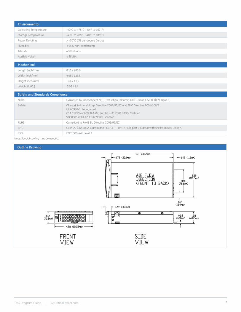
Length (inch/mm) 8.11 / 206.0
Width (inch/mm) 4.98 / 126.5
Height (inch/mm) 1.64 / 41.6
Weight (lb/Kg) 3.08 / 1.4
Outline Drawing

DAS Program Guide | GECriticalPower.com8
Pulsar Edge Controller
Applications
Key Features
The SPS Pulsar Edge controller delivers large system intelligence in a small system form factor. This family of controllers functions as network interface cards (NIC) and as a full-featured battery plant controller. Its thin modular plug-in form factor minimizes shelf space consumption allowing maximum power module and distribution capabilities.
The controller is utilized in bulk power applications in data centers and enterprise applications. Ethernet connectivity with SNMP facilitates remote network management. Access through its front-accessible RS232 or USB port and aided by the EasyView2 graphical enables full user interface locally. Optional 1U display version allows convenient access to all controller functions without requiring external cable connections. The display also features alarm context sensitive backlighting for at-a-glance system status.
As a battery plant controller, it provides a complete set of features to monitor and control rectifiers, batteries, and distribution. A flexible set of configurable inputs allow
the Pulsar Edge controller to monitor a wide variety of system equipment and incorporate appropriate state information enabling a centralized point of management.
The controller utilizes standard network management protocols allowing for advanced network supervision. GE Galaxy Manager* software is the centralized visibility and control component of a comprehensive power management system designed to meet engineering, operations and maintenance needs. The Galaxy Manager client-server architecture enables remote access to system controllers across the power network.
• Telecommunications networks• Digital subscriber line (DSL) • Indoor/outdoor wireless
• Routers/switches • Fiber in the loop• Transmission
• Data networks• PBX
Remote Access and Features• Integrated 10/100Base-T Ethernet Network
- TCP/IP - SNMP V2c for management - SMTP for email - Telnet for command line interface - DHCP for plug-n-play - FTP for rapid backup and upgrades - HTTP for standard web pages and browsers - Compatible with Galaxy Manager and other management packages - Shielded RJ-45 interface referenced to chassis ground
• Password protected security levels: User, Super-User, Administrator for all access
• Ground-referenced RS232 system port • ANSI T1.317 command-line interface• Modem access support
- Remote via external modem - Callback security
• EasyView2, Windows-based GUI software for local terminal or Modem access
• Optional 1U display with alarm indicating backlight feature
Standard System Features• Monitor and control of more than 40
connected devices - Maximum of 32 rectifiers - Maximum of 6 distribution control cards - Robust RS485 system bus
• Standard and user defined alarms - Alarm test - Assignable alarm severity: Critical, Major, Minor, Warning, and record-only
• Rectifier management features - Automatic rectifier restart - Adaptive Rectifier Management (energy efficiency) - Remote rectifier (on/off) - Reserve Operation - Automatic rectifier sequence control - N + X redundancy check
• Multiple Low Voltage Load and Low Voltage Battery Disconnect thresholds (4)
• Configuration, statistics, and history - All stored in non-volatile memory - Remote/local backup and restore of configuration data
• Industry standard defaults - Customer specific configurations available
• Remote/ local software upgrade• Basic, busy hour, and trend statistics• Detailed event history • User defined events and derived channels
Standard Battery Management Features• Float/boost mode control
- Manual boost - Manual timed boost locally, T1.317, and remotely initiated - Auto boost terminated by time or current
• Battery discharge testing - Manual (local/remote) - Periodic - Plant Battery Test (PBT) input driven - Configurable threshold or 20% algorithm - Graphical discharge data - Rectifiers on-line during test
• Slope thermal compensation - High temperature - Low temperature - Step temperature - STC Enable/Disable, low temperature Enable/Disable - Configurable mV/°C slopes
• State of charge indication• High temperature disconnect setting• Reserve-time prediction• Recharge current limit• Emergency Power-Off input

DAS Program Guide | GECriticalPower.com 9
Integrated Monitoring Inputs/Outputs• System plant voltage (accuracy ±0.5%, resolution 0.01V)
• One system shunt (accuracy ±1% full scale, resolution 1A) - Battery or load - Mounted in the return side of DC bus
• Up to 15 binary inputs - Six inputs close/open to battery - 9 input close/open to return (number is dependent upon number of output alarms) - User assignable
• Up to 5 user assignable Form-C output alarms (50VDC @.3A)
• 1-Wire* bus devices - Up to 16 temperature probes (QS873) - Up to 6 mid-string monitors (ES771)
Galaxy Manager Compatible• Centralized web server and database with multiple user access to
live or managed data with drill down to problem details
• Monitor and control of more than 40 connected devices
• Management information from polling or alarms received from alarm traps from multiple sites are available on one screen via the inter/intranet
• Trend user selected data over time
• Automatic or manual report generation
• Standard engineering tools like reserve time calculators and cable voltage drop analyzer
General
Operating Voltage ±24 Vdc, ±48 Vdc (Range: ±18 to ±60 Vdc)
Input Power Less than 7W
Operating Temperature Range -40°C to +70°C (-40°F to 167°F)
Operating Relative Humidity 0 - 95% (non-condensing)
Storage Temperature Range -40°C to +85°C (-40°F to 185°F)
Physical Specifications 1.75 in. H, 0.75 in. W, 8.00 in. D; 0.5lb
Display 8-line by 40-character backlit LCD
EMC FCC/EN55022 Class A, CISPR22 Level A
Agency Certifications
Electrostatic Discharge EN 61000-4-2 level 4
Radiated Emissions FCC, Class A; EN 55022, Class A
Safety UL Listed Component as Part of CPL or SPS Power System
Controller
Ordering Code Description Photo
CC109142238 SPS841A_3C3R Controller
CC109156898 SPS841A_0I5R Controller
150027896 SPS841A_9I0R Controller
Rectifier Module
Ordering Code Description Photo
150027894 500W RectifierEP0500-UTEZ
CC109165602 1000W RectifierEP1000-UTEZ
CC109165610 1600W Rectifier EP1600-UTEZ

DAS Program Guide | GECriticalPower.com10
Ordering Information – Slimline Power System
1RU Shelves
Ordering Code Description Rectifier Slots DC Output Battery
Breakers LVD AC Input
CC109148136 J2007003L001 3 Bulk Rear 0 None Single IEC C19
CC109146503 J2007003L001A 3 Bulk Rear 0 None Individual IEC C13
CC109148144 J2007003002 2 6 GMT's Front 1 LVBD Single IEC C13
CC109165890 J2007003002D 2 6 GMT's / Door Front 1 LVBD Single IEC C13
CC109151536 J2007003002A 2 6 GMT's Front 1 LVBD Individual IEC C13
CC109165916 J2007003002AD 2 6 GMT's / Door Front 1 LVBD Individual IEC C13
CC109156907 J2007003002X 2 6 GMT's Front 1 None Single IEC C13
CC109165908 J2007003002XD 2 6 GMT's / Door Front 1 None Single IEC C13
CC109156915 J2007003'002AX 2 6 GMT's Front 1 None Individual IEC C13
CC109165924 J2007003002AXD 2 6 GMT's / Door Front 1 None Individual IEC C13
CC109158696 J2007003002AXB 2 6 GMT's Front 0 None Single IEC C13
CC1091659232 J2007003002AXBD 2 6 GMT's / Door Front 0 None Single IEC C13
CC109146511 J2007003004 2 10 GMT's Rear 2 LVBD Single IEC C13
CC109156923 J2007003004X 2 10 GMT's Rear 2 None Single IEC C13
150026024 J2007003004XB 2 10 GMT's Rear 0 None Single IEC C13
CC109151544 J2007003004A 2 10 GMT's Rear 2 LVBD Individual IEC C13
CC109156931 J2007003004AX 2 10 GMT's Rear 2 None Individual IEC C13
150024564 J2007003004AXB 2 10 GMT's Rear 0 None Individual IEC C13
CC109156114 J2007003011 3 12 GMT's Rear 0 None Single IEC320 C19
CC109159372 J2007003014 2 1-30A Brkr / 10 GMT's Rear 1 LVBD Rear Terminal
150033629 J2007003014LA 2 1-30A Brkr / 10 GMT's Rear 1 LVLD Single IEC C13
150030787 J2007003014XA 2 1-30A Brkr / 10 GMT's Rear 1 None Single IEC C13
AC Input , DC Output Cables (105˚C Wire)
C13 plug with 5-15P plug, 14AWG, 10’ CC848776105
C13 plug with L6-20P plug, 14AWG, 10’ CC848820317
C13 plug, unterminated, 14AWG, 10’ 847861192
C13 AC Cord Retaining Clamp CC848885698
C19 plug, with 5-15P plug, 12AWG, 8’ CC848850792
C19 plug, with L6-20P plug, 12AWG, 8’ (List 1 Only) CC848850842
C19 plug, unterminated, 12AWG, 8’ (List 1) CC848847368
C19 AC Cord Retaining Clamp CC848887158
DC output cable 2 AWG, 10’ (List 1, 1A only) 848748987
AC Input , DC Output Cables (105˚C Wire)
5’ Alarm (J1) or distribution (J7) cable CC848890153
15’ Alarm (J1) or distribution (J7) cable CC848865980
50’ Alarm (J1) or distribution (J7) cable CC848817651
5’ Alarm input cable (J2) CC848890203
15’ Alarm input cable (J2) CC848853614
50’ Alarm input cable (J2) CC848890211
Shelf to shelf communication cable (J4) (List 1, 1A only)
CC848847780

DAS Program Guide | GECriticalPower.com 11
Stackable Shelf Solutions
Ordering Code Description Load Breaker Positions
Load GMT Fuse Positions
Battery Breaker Positions
LVD Photo
150030465 -48V, 2U SPS Power ShelfSPS-2U-AC5-PS3-DC12-LVBD
2 12 2 LVBD
150032350 -48V, 2U SPS Power ShelfSPS-2U-AC5-PS3-DC24B-LVBD
0 24 2 LVBD
1RU Distribution Shelves
Ordering Code Description Load Breaker
Positions
Load GMT Fuse Positions
Battery Breaker
Positions
LVD Photo
150032397 -48V, 1RU SPS Distribution ShelfJ2013001L101B
2 0 2 LVBD
150032400 -48V, 1RU SPS Distribution ShelfJ2013001L106
4 0 0 No
150032401 -48V, 1RU SPS Distribution ShelfJ2013001L107
0 36 0 No
Bulk Shelves
Ordering Code Description AC Input Rectifier Slots
Controller Support
DC Output
Photo
150028854 -48V, 1RU SPS Supplemental Bulk ShelfJ2007003L052C
Rear AC Terminal
3 No Rear Bulk
2RU Shelves and Larger

DAS Program Guide | GECriticalPower.com12
Notes

DAS Program Guide | GECriticalPower.com 13
Fuse / Circuit Breaker PanelsDistribution protector options include:
• 6 position GMT bullet fuseholder
• 6 position 0-125A TPS/TLS fuseholder
• 22 position 0-250A circuit breakers for 23” wide panels
VIM 1 Intelligent MeterTypical DC distribution panels have a simple 477C alarm card that indicates a breaker/fuse alarm with a visual red alarm light and an isolated closure for remote monitoring. The SPDU provides a digital smart meter for more extensive monitoring and control. The is the same smart meter used in the large H569-445 BDFB. The VIM1 monitor, or smart meter, has an alarm sensitive back-lit display that changes color from green to red on alarm. Current, voltage and alarm information for the A and B buses are accessed thru the display. There are three primary alarms:
Power Loss/Under Voltage: Generates an alarm when power is lost to either the A or B bus; or when a user configurable low voltage threshold is reached.
Overload: Generates an alarm when a user configurable current threshold is reached. A configurable time delay may also be set to avoid nuisance alarms due to bus transients.
Breaker/Fuse: Generates an alarm when either a circuit breaker trips or a fuse blows.
The VIM 1 digital meter includes an audible alarm with a user configurable on/off feature. There is a form-C relay for each of the three alarms for remote monitoring - power loss/under voltage, current overload/threshold exceeded, and blown fuse/breaker trip. There are two RJ45 type connectors on the board that allow multiple VIM 1 boards to be daisy chained together for network connectivity.
Feature and Benefits• Ideal for premise power applications
• Digital meter interface
• 600 Amp capacity panels in a compact 4 RU size
• Small power distribution from battery plant to load equipment
The GE SPDU serves as a secondary power distribution center for +24Vdc or -48Vdc DC power delivered from a battery plant to the load equipment. The 4U (7 in.) tall configuration is versatile with 19” or 23” rack or wall mounted panels with fuse or circuit breakers options, single or dual (A/B) load bus, and 600A carrying capacity per panel (300A per bus in dual load bus configurations.) A digital meter monitors voltage and current of each load bus.
SPDUSecondary Power Distribution Unit

DAS Program Guide | GECriticalPower.com14
SpecificationsMechanical
Height 7 in. (175.7mm)
Width 19 in. (484mm) or 23 in. (586mm)
Depth 5 in. (127mm)
Weight Approx 15.2 lbs (7kg)
Agency Certifications
Telcordia NEBs Level 3 Compliant
UL Canada/US UL60950/UL1801
CE CE mark
EMI/EMC CISPR class A conducted and radiated
Outline Drawing (for visual reference only)
23” DC Distribution Panel with 477C alarm card
DAS Program Guide | GECriticalPower.com 15
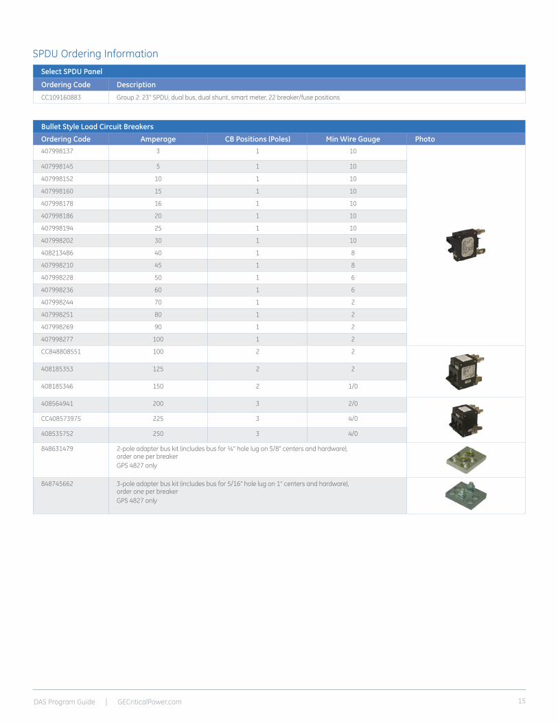
SPDU Ordering InformationSelect SPDU Panel
Ordering Code Description
CC109160883 Group 2: 23” SPDU, dual bus, dual shunt, smart meter, 22 breaker/fuse positions
Bullet Style Load Circuit Breakers
Ordering Code Amperage CB Positions (Poles) Min Wire Gauge Photo407998137 3 1 10
407998145 5 1 10
407998152 10 1 10
407998160 15 1 10
407998178 16 1 10
407998186 20 1 10
407998194 25 1 10
407998202 30 1 10
408213486 40 1 8
407998210 45 1 8
407998228 50 1 6
407998236 60 1 6
407998244 70 1 2
407998251 80 1 2
407998269 90 1 2
407998277 100 1 2
CC848808551 100 2 2
408185353 125 2 2
408185346 150 2 1/0
408564941 200 3 2/0
CC408573975 225 3 4/0
408535752 250 3 4/0
848631479 2-pole adapter bus kit (includes bus for ¼” hole lug on 5/8” centers and hardware), order one per breakerGPS 4827 only
848745662 3-pole adapter bus kit (includes bus for 5/16” hole lug on 1” centers and hardware), order one per breakerGPS 4827 only

DAS Program Guide | GECriticalPower.com16
Notes
DAS Program Guide | GECriticalPower.com 17
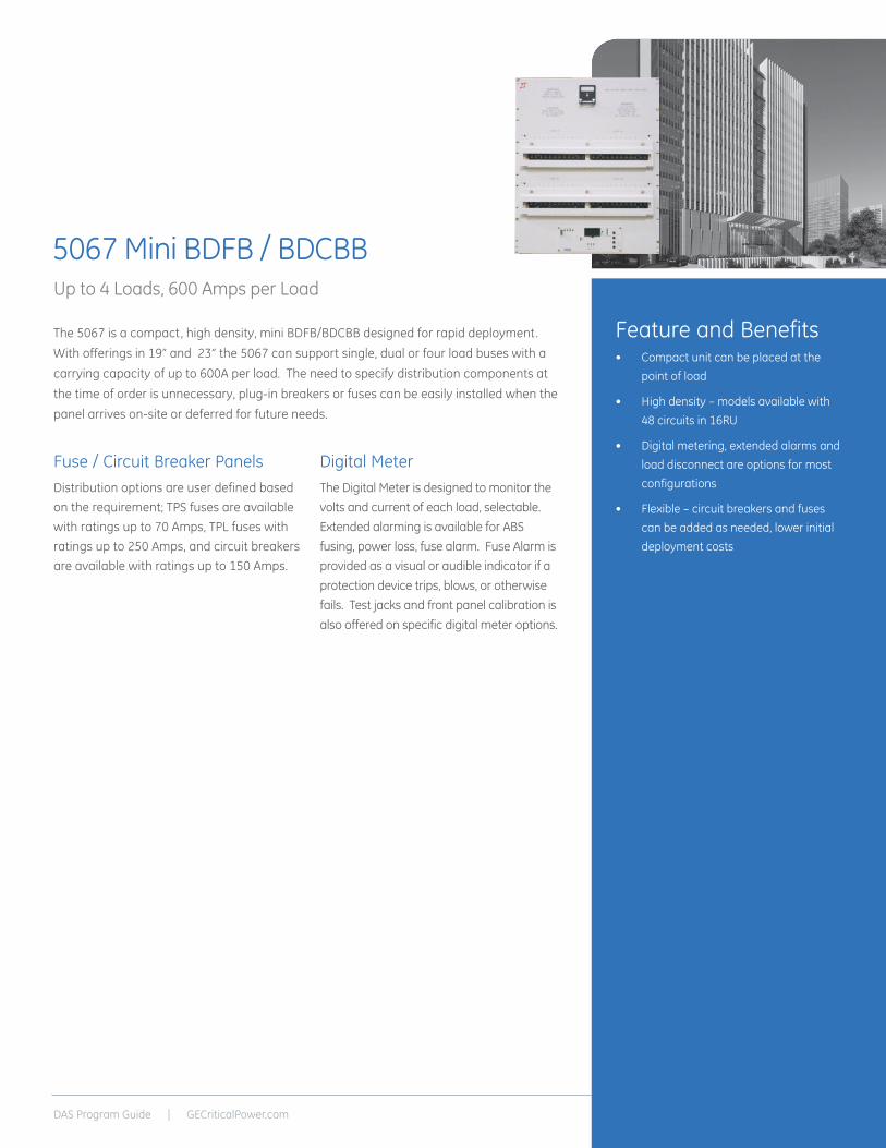
Fuse / Circuit Breaker PanelsDistribution options are user defined based on the requirement; TPS fuses are available with ratings up to 70 Amps, TPL fuses with ratings up to 250 Amps, and circuit breakers are available with ratings up to 150 Amps.
Digital MeterThe Digital Meter is designed to monitor the volts and current of each load, selectable. Extended alarming is available for ABS fusing, power loss, fuse alarm. Fuse Alarm is provided as a visual or audible indicator if a protection device trips, blows, or otherwise fails. Test jacks and front panel calibration is also offered on specific digital meter options.
Feature and Benefits• Compact unit can be placed at the
point of load
• High density – models available with 48 circuits in 16RU
• Digital metering, extended alarms and load disconnect are options for most configurations
• Flexible – circuit breakers and fuses can be added as needed, lower initial deployment costs
The 5067 is a compact, high density, mini BDFB/BDCBB designed for rapid deployment. With offerings in 19” and 23” the 5067 can support single, dual or four load buses with a carrying capacity of up to 600A per load. The need to specify distribution components at the time of order is unnecessary, plug-in breakers or fuses can be easily installed when the panel arrives on-site or deferred for future needs.
5067 Mini BDFB / BDCBBUp to 4 Loads, 600 Amps per Load

DAS Program Guide | GECriticalPower.com18
SpecificationsCurrent 6180638P
Maximum Load 1200A
Per Load 600A
Load Complement 2 or 4
Distribution Positions 48 plug in
Mechanical 6180638P
Width (inch/mm) 23 / 584
Depth (inch/mm) 15.25 / 387
Height (inch/mm) 27.97 / 710
Outline Drawing
6180638P-3
6180638P
Safety and Standards Compliance
NEBS Evaluated by independent NRTL test lab to Telcordia GR63, Issue 4 & GR 1089, Issue 6
Safety UL60950-04, UL198L, UL489
DAS Program Guide | GECriticalPower.com 19
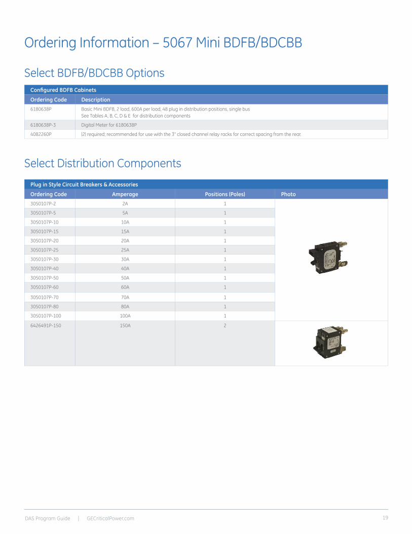
Ordering Information – 5067 Mini BDFB/BDCBB
Select BDFB/BDCBB Options
Select Distribution Components
Configured BDFB Cabinets
Ordering Code Description
6180638P Basic Mini BDFB, 2 load, 600A per load, 48 plug in distribution positions, single busSee Tables A, B, C, D & E for distribution components
6180638P-3 Digital Meter for 6180638P
4082260P (2) required; recommended for use with the 3" closed channel relay racks for correct spacing from the rear.
Plug in Style Circuit Breakers & Accessories
Ordering Code Amperage Positions (Poles) Photo
3050107P-2 2A 1
3050107P-5 5A 1
3050107P-10 10A 1
3050107P-15 15A 1
3050107P-20 20A 1
3050107P-25 25A 1
3050107P-30 30A 1
3050107P-40 40A 1
3050107P-50 50A 1
3050107P-60 60A 1
3050107P-70 70A 1
3050107P-80 80A 1
3050107P-100 100A 1
6426491P-150 150A 2

DAS Program Guide | GECriticalPower.com20
Notes

DAS Program Guide | GECriticalPower.com 21
Infinity Power SystemsGE Infinity Power Systems are modular power plants that support dual voltage (+24V/-48V) operation through the use of a comprehensive range of advanced rectifiers and DC/DC converter modules. Primary voltage is supported by rectifiers and battery reserve, while the optional secondary voltage is supported by DC/ DC converter modules.
The RBA72 Power Cabinet is equipped with the Infinity S DC energy system that supports dual voltage (-48V/+24V) operation. The cabinet provides individual compartments for the power equipment and batteries. A dual loop heat exchanger allows for temperature control of the battery compartment while allowing the equipment to run at its designed range for maximum cooling cost efficiency.
Infinity Rectifier and Converter FamilyThe Infinity Series offers DC rectifiers and converters for both +24V to -48V and -48V to +24V applications. For easy module selection, the rectifiers and converters are color coded to quickly identify voltage, module type and input voltage type (AC or DC).
Galaxy Pulsar* Plus ControllerThe Galaxy Pulsar Plus is used throughout many of the GE DC Power products including Infinity, CP, and SPS with the only differentiator being the form factor which is scaled to meet the nature of the application. The controller utilizes standard network management protocols allowing for advanced network supervision with SNMP communications to deliver extensive monitoring and control features with both local and remote access.
Reliability– Proven field performance
– Excellent fault tolerance
Intelligence– Ethernet interface for remote access
and SNMP capability
– Centralized network management
– Industry leading control features
Investment Protection– Module Compatibility
– Power Shelf Growth
– Secondary Voltage flexibility +24V / -48V
– Flexible upgrade options
On Time Delivery– MWBE warehouse utilized for
immediate availability
– 24/7 technical support
– Common building blocks for both positive and negative output models
Benefits
• ECO Priority Source*
Ready
• Dual Voltage power system with ultimate flexibility
• -48V up to 1,600A (86KW) or +24V up to 1,600A (44KW)
• Secondary Voltage Load capacity up to 600A
• High availability wireless telecom applications
• Telecom service providers
• Efficiency approaching 97%

DAS Program Guide | GECriticalPower.com22
Infinity Rectifiers and Converters
Applications
Key Features
Specifications
• Compact – 1RU form factor providing high power density (24 W/in3)
• Dual Voltage compatibility – the unique connector pin designation allows the rectifier to be used in a “universal” power shelf, alongside rectifiers or DC-DC converters with different output voltages.
• Plug and Play – installation of the rectifier in a shelf connected to a compatible system controller initializes all set up parameters automatically. No adjustments are needed.
• Extended service life – parallel operation with automatic load sharing ensures that parallel units are not unduly stressed even when a unit fails or is removed.
• Monitoring / control – the built in microprocessor controls and monitors all critical rectifier functions and communicates with the system controller using the built in Galaxy Protocol serial interface.
• Fail safe performance – hot insertion capabilities allow for converter replacement without system shutdown; soft start and inrush current protection prevent nuisance tripping of upstream breakers.
• Telecommunications Networks
• Digital Subscriber Line (DSL)
• Indoor/Outdoor Wireless
• Routers/Switches
• Fiber in the Loop
• Transmission
• Data Networks
• Distributed Antenna Systems
• Off-Grid/On-Grid Renewable Energy Sites
• Extended temperature range
• Redundant fan cooling
• Front panel LED indicators
• 1U height, hi power density
• 220/110V AC input
• Digital load sharing
• Hot pluggable
• RoHS compliant
• Direct solar input (no inverter required)
InputNE100AC24ATEZ NE100ECO24ATEZ
NE050AC48ATEZ NE050ECO48ATEZ
NE075AC48ATEZ NE030DC48A NE040DC48AZ NE075DC24A
Voltage Range 95-275Vac 95-275Vac 95-275Vac 21-30Vdc 21-30Vdc 42-60Vdc
Input Current 15-12A @ 100-120Vac15-12A @ 200-240Vac
15-12A @ 100-120Vac15-12A @ 200-240Vac
15-12A @ 100- 120Vac22-18A @ 200-240Vac
63A @ 27Vdc81A @ 21Vdc
94A @ 27Vdc108A @ 21Vdc
41A @ 54.5Vdc54A @ 42Vdc
Input Frequency 45 – 66Hz 45 – 66Hz 45 - 66Hz - - -
Power Factor 0.98 at>50% load 0.98 at>50% load 0.98 at>50% load - - -
Efficiency > 95% (Peak 95.6%) > 96% (Peak 96.9%) > 96% (Peak 96.9%) - - -
Total Harmonic Distortion
<5% @loads over 50% <5% @loads over 50% <5% @loads over 50% - - -
Output
Voltage Adjust Range
21-29Vdc 42-58Vdc 42-58Vdc 46-57Vdc 46-57Vdc 23-28Vdc
Voltage Nominal 27.25V 54.5V 54.5V 52.0V 52.0V 27.2V
Regulation (with controller)
±0.5% ±0.5% ±0.5% ±0.5% ±0.5% ±0.5%
Ripple 100mVrms 100mVrms 100mVrms 100mVrms 100mVrms 100mVrms
Output Current - High-Line
- Low-Line
114A @24V100A @27.25V44A @27.25V
57A @48V50A @54.5V 22A @54.5V
85A @48V75A @54.5V22A @54.5V
30A @52.0V--
40A @52.0V--
75A @27.2V--
Heat Dissipation @ max out
174W / 594 BTU/hr 158W / 539 BTU/hr 249W / 850 BTU/hr 154W / 525 BTU/hr
205W / 700 BTU/hr
202W / 689 BTU/hr
DAS Program Guide | GECriticalPower.com 23
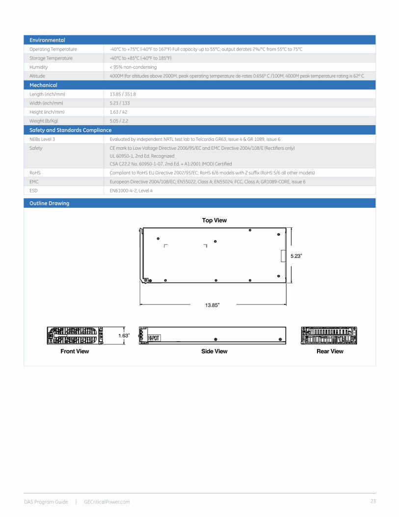
Outline Drawing
Environmental
Operating Temperature -40°C to +75°C (-40°F to 167°F) Full capacity up to 55°C; output derates 2%/°C from 55°C to 75°C
Storage Temperature -40°C to +85°C (-40°F to 185°F)
Humidity < 95% non-condensing
Altitude 4000M (for altitudes above 2000M, peak operating temperature de-rates 0.656º C /100M; 4000M peak temperature rating is 62º C
Mechanical
Length (inch/mm) 13.85 / 351.8
Width (inch/mm) 5.23 / 133
Height (inch/mm) 1.63 / 42
Weight (lb/Kg) 5.05 / 2.2
Safety and Standards Compliance
NEBs Level 3 Evaluated by independent NRTL test lab to Telcordia GR63, Issue 4 & GR 1089, Issue 6
Safety CE mark to Low Voltage Directive 2006/95/EC and EMC Directive 2004/108/E (Rectifiers only)
UL 60950-1, 2nd Ed. Recognized
CSA C22.2 No. 60950-1-07, 2nd Ed. + A1:2001 (MOD) Certified
RoHS Compliant to RoHS EU Directive 2002/95/EC; RoHS 6/6 models with Z suffix (RoHS 5/6 all other models)
EMC European Directive 2004/108/EC; EN55022, Class A; EN55024; FCC, Class A; GR1089-CORE, Issue 6
ESD EN61000-4-2, Level 4

DAS Program Guide | GECriticalPower.com24
Pulsar Plus Controller
Applications
Key Features
The Pulsar Plus family of controllers provides system monitoring and control features for Infinity, CP, and other power systems. These controllers monitor and control system components including rectifiers, converters, and distribution modules via a multi-drop RS485 digital communications bus. System status, parameters, settings, and alarm thresholds can be viewed and configured from the controller’s front panel display. Assignment and configuration of alarm inputs and output relays can be performed from a laptop computer connected to a local RS-232 or Ethernet port, or by remote access is through a network connection to the World Wide Web (internet) or your enterprise network (intranet). An optional modem is also available.
This controller utilizes standard network management protocols allowing for advanced network supervision. The GE Galaxy Manager* software is the centralized visibility and control component of a comprehensive power management system designed to meet engineering, operations and maintenance needs. The Galaxy Manager client-server architecture enables remote access to system controllers across the power network, featuring ECO Priority advanced monitoring features which provides detailed energy source analysis to help better customize your renewable energy resources.
• Telecommunications Networks
• Digital Subscriber Line (DSL)
• Indoor/Outdoor Wireless
• Routers/Switches
• Fiber in the Loop
• Transmission
• Data Networks
• PBX
• Off-Grid/On-Grid Renewable Energy Sites
Remote Access and Features• Integrated 10/100Base-T Ethernet Network
- TCP/IP - SNMP V2c for management - SMTP for email - Telnet for command line interface - DHCP for plug-n-play - FTP for rapid backup and upgrades - HTTP for standard web pages and browsers - Compatible with Galaxy Manager and other management packages - Shielded RJ-45 interface referenced to chassis ground
• Password protected security levels: User, Super-User, Administrator for all access
• Ground-referenced RS232 system port • ANSI T1.317 command-line interface• Modem access support
- Remote via external modem - Callback security
• EasyView2, Windows-based GUI software for local terminal or Modem access
• ECO Priority controls and features - Advanced generator controls to help
minimize fuel consumption for off grid applications
- ECO Energy Management allowing for non-ECO sources outputs to be minimized while ECO resources are available
- Source and load trend logging
Standard System Features• Monitor and control of more than 40
connected devices - Robust RS485 system bus
• Standard and user defined alarms - Alarm test - Assignable alarm severity: Critical, Major, Minor, Warning, and record-only - 10 alarm relays (7 user assigned)
• Rectifier management features - Automatic rectifier restart - Active Rectifier Management ARM (energy efficiency) - Remote rectifier (on/off) - Reserve Operation - Automatic rectifier sequence control - N + X redundancy check
• Multiple Low Voltage Load and Low Voltage Battery Disconnect thresholds
• Configuration, statistics, and history - All stored in non-volatile memory - Remote/local backup and restore of configuration data
• Industry standard defaults - Customer specific configurations available
• Remote/ local software upgrade• Basic, busy hour, and trend statistics• Detailed event history • User defined events and derived channels
Standard Battery Management Features• Float/boost mode control
- Manual boost - Manual timed boost locally, T1.317, and remotely initiated - Auto boost terminated by time or current
• Battery discharge testing - Manual (local/remote) - Periodic - Plant Battery Test (PBT) input driven - Configurable threshold or 20% algorithm - Graphical discharge data - Rectifiers on-line during test
• Slope thermal compensation - High temperature - Low temperature - Step temperature - STC Enable/Disable, low temperature Enable/Disable - Configurable mV/°C slopes
• State of charge indication• High temperature disconnect setting• Reserve-time prediction• Recharge current limit• Emergency Power-Off input

DAS Program Guide | GECriticalPower.com 25
Integrated Monitoring Inputs/Outputs• System plant voltage (accuracy ±0.5%, resolution 0.01V)
• One system shunt (accuracy ± 0.5% full scale, resolution 1A) - Battery or load - Mounted in the return side of DC bus
• Up to 15 binary inputs - Six inputs close/open to battery - 9 input close/open to return - User assignable
• Up to 7 Form-C output alarms (60VDC @ .5A) - User assignable
• 1-Wire* bus devices - Up to 16 temperature probes (QS873) - Up to 6 mid-string monitors (ES771)
Galaxy Manager Compatible• Centralized web server and database with multiple user access to
live or managed data with drill down to problem details
• Monitor and control of more than 40 connected devices
• Management information from polling or alarms received from alarm traps from multiple sites are available on one screen via the inter/intranet
• Trend user selected data over time
• Automatic or manual report generation
• Standard engineering tools like reserve time calculators and cable voltage drop analyzer
General
Operating Voltage ±24 Vdc, ±48 Vdc (Range: ±18 to ±60 Vdc)
Input Power Less than 7W
Operating Temperature Range -40°C to +75°C (-40°F to 167°F)
Operating Relative Humidity 0 - 95% (non-condensing)
Storage Temperature Range -40°C to +85°C (-40°F to 185°F)
Physical Specifications Sizes vary by packaging option
Display 8-line by 40-character with alarm context sensitive backlit LCD
No Alarms
No Alarms
Agency Certifications
NEBs Level 3 Evaluated by independent NRTL test lab to Telcordia GR63, Issue 4 and GR1089-CORE, Issue 6
EMC European Directive 2004/108/EC; EN55022, (CISPR22) Class A, EN55024 (CISPR24)
Safety Underwriters Laboratories (UL) Listed per Subject Letter 1801: Power Distribution Center for Communications Equipment, and cUL Certified (CSA 22.2 950): Safety of Information Technology Equipment
Safety and Standards Compliance
NEBs Evaluated by independent NRTL test lab to Telcordia GR63, Issue 4 and GR1089-CORE, Issue 6
Safety CSA C22.2 No. 60950-1-07, 2nd Ed. + A1:2001 (MOD) Certified for Canada and U.S.; UL60950-1 1st Ed.
RoHS Compliant to RoHS EU Directive 2002/95/EC RoHS 5/6
EMC European Directive 2004/108/EC; EN55022, Class A, EN55024; FCC, Class A; GR1089-CORE, Issue 6
DAS Program Guide | GECriticalPower.com26
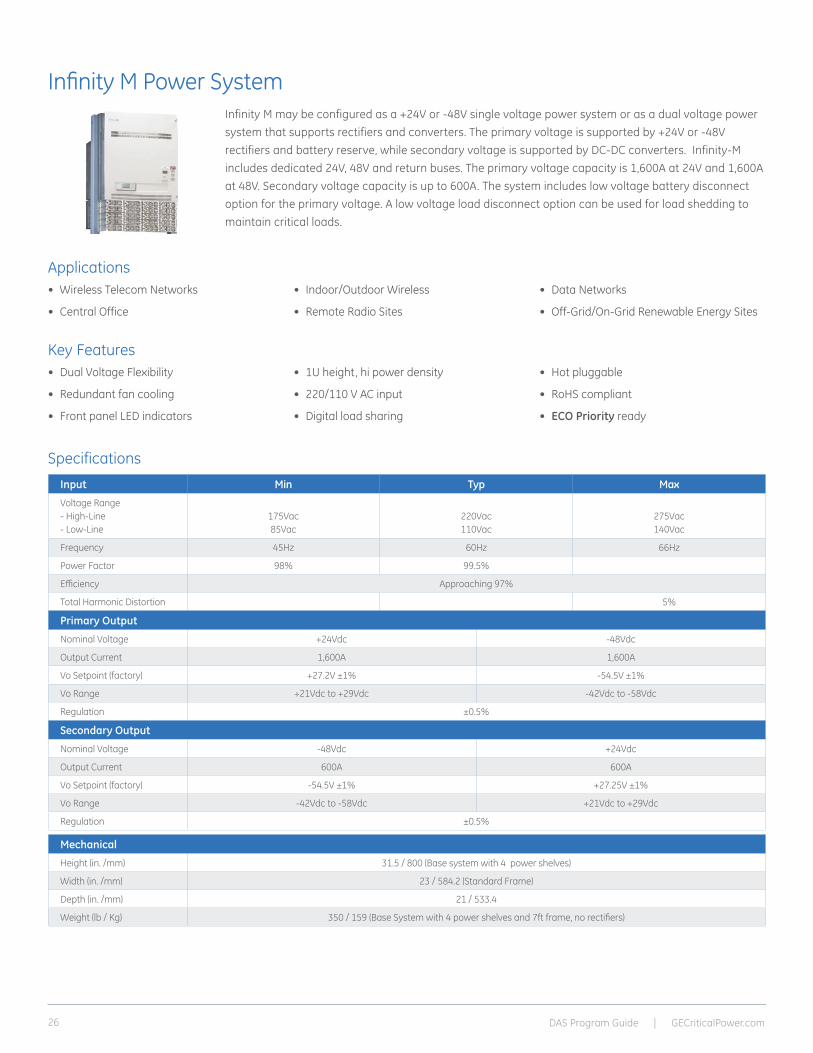
Infinity M Power System
Applications
Key Features
Specifications
Infinity M may be configured as a +24V or -48V single voltage power system or as a dual voltage power system that supports rectifiers and converters. The primary voltage is supported by +24V or -48V rectifiers and battery reserve, while secondary voltage is supported by DC-DC converters. Infinity-M includes dedicated 24V, 48V and return buses. The primary voltage capacity is 1,600A at 24V and 1,600A at 48V. Secondary voltage capacity is up to 600A. The system includes low voltage battery disconnect option for the primary voltage. A low voltage load disconnect option can be used for load shedding to maintain critical loads.
• Wireless Telecom Networks
• Central Office
• Indoor/Outdoor Wireless
• Remote Radio Sites
• Data Networks
• Off-Grid/On-Grid Renewable Energy Sites
• Dual Voltage Flexibility
• Redundant fan cooling
• Front panel LED indicators
• 1U height, hi power density
• 220/110 V AC input
• Digital load sharing
• Hot pluggable
• RoHS compliant
• ECO Priority ready
Input Min Typ Max
Voltage Range - High-Line - Low-Line
175Vac 85Vac
220Vac110Vac
275Vac140Vac
Frequency 45Hz 60Hz 66Hz
Power Factor 98% 99.5%
Efficiency Approaching 97%
Total Harmonic Distortion 5%
Mechanical
Height (in. /mm) 31.5 / 800 (Base system with 4 power shelves)
Width (in. /mm) 23 / 584.2 (Standard Frame)
Depth (in. /mm) 21 / 533.4
Weight (lb / Kg) 350 / 159 (Base System with 4 power shelves and 7ft frame, no rectifiers)
TECHNICAL SPECIFICATIONS – SYSTEM
Primary Output
Nominal Voltage +24Vdc -48Vdc
Output Current 1,600A 1,600A
Vo Setpoint (factory) +27.2V ±1% -54.5V ±1%
Vo Range +21Vdc to +29Vdc -42Vdc to -58Vdc
Regulation ±0.5%
Secondary Output
Nominal Voltage -48Vdc +24Vdc
Output Current 600A 600A
Vo Setpoint (factory) -54.5V ±1% +27.25V ±1%
Vo Range -42Vdc to -58Vdc +21Vdc to +29Vdc
Regulation ±0.5%

DAS Program Guide | GECriticalPower.com 27
Outline Drawing (for visual reference only)
Environmental
Operating Temperature -40°C to +75°C (-40°F to 167 °F)
Storage Temperature -40°C to +85°C (-40°F to 185 °F)
Relative Humidity 95% max, non-condensing
Altitude 4000M (for altitudes above 2000M, peak operating temperature de-rates 0.656 Cº /100M; 4000M peak temperature rating is 62 Cº
Safety and Standards Compliance
NEBs Evaluated by independent NRTL test lab to Telcordia GR63, Issue 4 and GR1089-CORE, Issue 6
Safety CSA C22.2 No. 60950-1-07, 2nd Ed. + A1:2001 (MOD) Certified for Canada and U.S.; UL60950-1 1st Ed.
RoHS Compliant to RoHS EU Directive 2002/95/EC RoHS 5/6
EMC European Directive 2004/108/EC; EN55022, Class A; EN55024; FCC, Class A; GR1089-CORE, Issue 6
Agency Certifications
CSA CSA C22.2 No 60950-1-07, 2nd Ed. + A1:2001 (MOD) and UL 60950-1 1st Ed
EMI/EMC European Directive 2004/108/EC; EN55022 (CISPR22) Class A; EN55024 (CISPR24)
NEBS LEVEL 3 GR1089-CORE, Issue 6
DAS Program Guide | GECriticalPower.com28
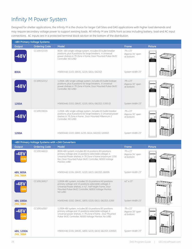
Infinity M Power SystemDesigned for shelter applications, the Infinity M is the choice for larger Cell Sites and DAS applications with higher load demands and may require secondary voltage power to support existing loads. All Infinity M are 100% front access including battery, load and AC input connections. AC inputs are in a protected terminal block section at the bottom of the distribution.
-48V Primary Voltage Systems
Output Ordering Code Model Frame Picture
-48VCC109152220 800A -48V single voltage system, includes 65 bullet breaker
positions, plus 8 positions for large breakers, 4 Universal power shelves in 7ft Zone 4 frame, Door Mounted Pulsar 843C Controller, NO LVBD
7ft x 23”(Approx 34” open at bottom)
800A H5692448, G103, G843C, G220, G614, G622(2) System Width 23”
-48VCC109152212 1,200A -48V single voltage system, includes 65 bullet brekaer
positions, plus 8 positions for large breakers, 6 Universal power shelves in 7ft Zone 4 frame, Door Mounted Pulsar 843C Controller, NO LVBD
7ft x 23”(Approx 30” open at bottom)
1200A H5692448, G103, G843C, G220, G614, G622(2), G300 (2) System Width 23”
-48VCC109159224 1,200A -48V single voltage system, includes 65 bullet breaker
positions, plus 8 positions for large breakers, 6 Universal power shelves in 7ft Zone 4 frame , Door Mounted Millennium 2 Controller, NO LVBD
7ft x 23” (Approx 30” open at bottom)
1200A H5692448, G103, G800, G220, G614, G622(2), G300(2) System Width 23”
-48V Primary Voltage Systems with +24V Converters
Output Ordering Code Model Frame Picture
CC109146610 800A 48V system, includes 80 cb positions (65 positions primary voltage and 15 positions selectable voltage), 4 Universal Power shelves, in 7ft Zone 4 frame (maximum 1200 lbs.), Door Mounted Pulsar 843C Controller, NE830 Voltage Monitor, LVBD
7ft x 23”(Approx 34” open at bottom)
48V, 800A24V, 300A
H5692448, G104, G843C, G220, G615, G622(2), G600N System Width 23”
CC109136917 1,000A 48V system, includes 55 cb positions (40 positions primary voltage and 15 positions selectable voltage), 5 Universal Power shelves, in 42", half height frame, Door Mounted Pulsar 843C Controller, NE830 Voltage Monitor, NO LVBD
42” x 23”
48V, 1000A24V, 300A
H5692448, G102, G843C, G830, G220, G615, G622(2), G300 System Width 23”
CC109142007 1,200A 48V system, includes 80 cb positions (65 positions primary voltage and 15 positions selectable voltage), 6 Universal power shelves, in 7ft Zone 4 frame , Door Mounted Pulsar 843C Controller, NE830 Voltage Monitor, No LVBD
7ft x 23” (Approx 30” open at bottom)
48V, 1200A24V, 300A
H5692448, G104, G843C, G830, G220, G618, G622(2), G300(2) System Width 23”
DAS Program Guide | GECriticalPower.com 29
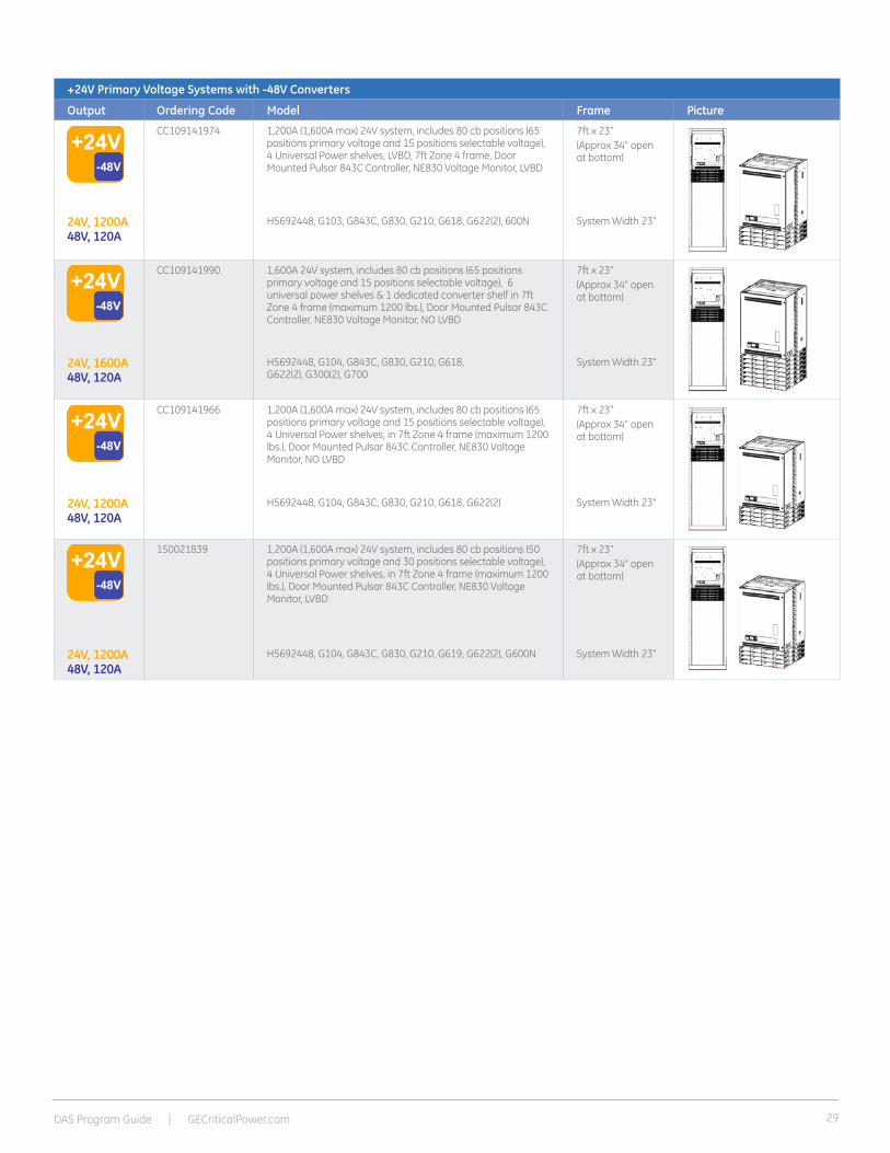
+24V Primary Voltage Systems with -48V Converters
Output Ordering Code Model Frame Picture
CC109141974 1,200A (1,600A max) 24V system, includes 80 cb positions (65 positions primary voltage and 15 positions selectable voltage), 4 Universal Power shelves, LVBD, 7ft Zone 4 frame, Door Mounted Pulsar 843C Controller, NE830 Voltage Monitor, LVBD
7ft x 23”(Approx 34” open at bottom)
24V, 1200A48V, 120A
H5692448, G103, G843C, G830, G210, G618, G622(2), 600N System Width 23”
CC109141990 1,600A 24V system, includes 80 cb positions (65 positions primary voltage and 15 positions selectable voltage), 6 universal power shelves & 1 dedicated converter shelf in 7ft Zone 4 frame (maximum 1200 lbs.), Door Mounted Pulsar 843C Controller, NE830 Voltage Monitor, NO LVBD
7ft x 23”(Approx 34” open at bottom)
24V, 1600A48V, 120A
H5692448, G104, G843C, G830, G210, G618, G622(2), G300(2), G700
System Width 23”
CC109141966 1,200A (1,600A max) 24V system, includes 80 cb positions (65 positions primary voltage and 15 positions selectable voltage), 4 Universal Power shelves, in 7ft Zone 4 frame (maximum 1200 lbs.), Door Mounted Pulsar 843C Controller, NE830 Voltage Monitor, NO LVBD
7ft x 23”(Approx 34” open at bottom)
24V, 1200A48V, 120A
H5692448, G104, G843C, G830, G210, G618, G622(2) System Width 23”
150021839 1,200A (1,600A max) 24V system, includes 80 cb positions (50 positions primary voltage and 30 positions selectable voltage), 4 Universal Power shelves, in 7ft Zone 4 frame (maximum 1200 lbs.), Door Mounted Pulsar 843C Controller, NE830 Voltage Monitor, LVBD
7ft x 23”(Approx 34” open at bottom)
24V, 1200A48V, 120A
H5692448, G104, G843C, G830, G210, G619, G622(2), G600N System Width 23”
DAS Program Guide | GECriticalPower.com30
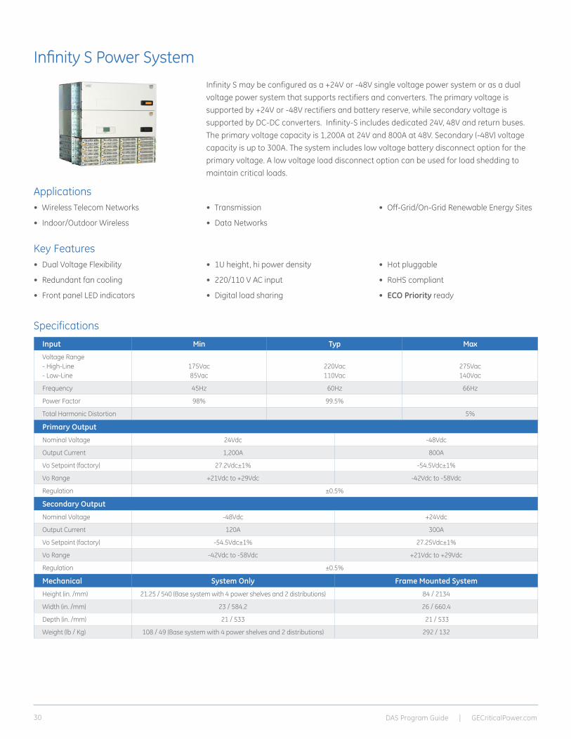
Infinity S Power System
Applications
Key Features
Infinity S may be configured as a +24V or -48V single voltage power system or as a dual voltage power system that supports rectifiers and converters. The primary voltage is supported by +24V or -48V rectifiers and battery reserve, while secondary voltage is supported by DC-DC converters. Infinity-S includes dedicated 24V, 48V and return buses. The primary voltage capacity is 1,200A at 24V and 800A at 48V. Secondary (-48V) voltage capacity is up to 300A. The system includes low voltage battery disconnect option for the primary voltage. A low voltage load disconnect option can be used for load shedding to maintain critical loads.
• Wireless Telecom Networks
• Indoor/Outdoor Wireless
• Transmission
• Data Networks
• Off-Grid/On-Grid Renewable Energy Sites
• Dual Voltage Flexibility
• Redundant fan cooling
• Front panel LED indicators
• 1U height, hi power density
• 220/110 V AC input
• Digital load sharing
• Hot pluggable
• RoHS compliant
• ECO Priority ready
SpecificationsInput Min Typ Max
Voltage Range - High-Line - Low-Line
175Vac 85Vac
220Vac110Vac
275Vac140Vac
Frequency 45Hz 60Hz 66Hz
Power Factor 98% 99.5%
Total Harmonic Distortion 5%
Primary Output
Nominal Voltage 24Vdc -48Vdc
Output Current 1,200A 800A
Vo Setpoint (factory) 27.2Vdc±1% -54.5Vdc±1%
Vo Range +21Vdc to +29Vdc -42Vdc to -58Vdc
Regulation ±0.5%
Secondary Output
Nominal Voltage -48Vdc +24Vdc
Output Current 120A 300A
Vo Setpoint (factory) -54.5Vdc±1% 27.25Vdc±1%
Vo Range -42Vdc to -58Vdc +21Vdc to +29Vdc
Regulation ±0.5%
Mechanical System Only Frame Mounted System
Height (in. /mm) 21.25 / 540 (Base system with 4 power shelves and 2 distributions) 84 / 2134
Width (in. /mm) 23 / 584.2 26 / 660.4
Depth (in. /mm) 21 / 533 21 / 533
Weight (lb / Kg) 108 / 49 (Base system with 4 power shelves and 2 distributions) 292 / 132
DAS Program Guide | GECriticalPower.com 31
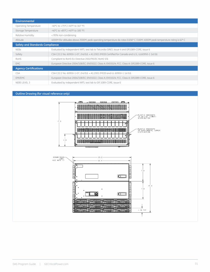
Outline Drawing (for visual reference only)
Environmental
Operating Temperature -40°C to +75°C (-40°F to 167 °F)
Storage Temperature -40°C to +85°C (-40°F to 185 °F)
Relative Humidity < 95% non-condensing
Altitude 4000M (for altitudes above 2000M, peak operating temperature de-rates 0.656º C /100M; 4000M peak temperature rating is 62º C
Safety and Standards Compliance
NEBs Evaluated by independent NRTL test lab to Telcordia GR63, Issue 4 and GR1089-CORE, Issue 6
Safety CSA C22.2 No. 60950-1-07, 2nd Ed. + A1:2001 (MOD) Certified for Canada and U.S.; UL60950-1 1st Ed.
RoHS Compliant to RoHS EU Directive 2002/95/EC RoHS 5/6
EMC European Directive 2004/108/EC; EN55022, Class A; EN55024; FCC, Class A; GR1089-CORE, Issue 6
Agency Certifications
CSA CSA C22.2 No. 60950-1-07, 2nd Ed. + A1:2001 (MOD) and UL 60950-1 1st Ed.
EMI/EMC European Directive 2004/108/EC; EN55022, Class A; EN55024; FCC, Class A; GR1089-CORE, Issue 6
NEBS LEVEL 3 Evaluated by independent NRTL test lab to GR 1089-CORE, Issue 6

DAS Program Guide | GECriticalPower.com32
Select Infinity S Power SystemDesigned for installations that require a small, low powered -48V power solution, this Infinity solution is perfect for small LTE and DAS sites.
Single Voltage Power System -48V, 19” width
Output Rating Description AC Input LVD Frame
Ordering Code
Model Photo
-48V
225A
225A Infinity S Power System equipped with 3 universal positions and 20 distribution positions selectable between -48V Load and Battery
Ind. Term Block No 150033064 NES48-19-AC5-PS3-DC1E
Ind. Term Block LVBD 150032370 NES48-19-AC5-PS3-DC1E-LVBD
-48V
600A
400A Infinity S Power System equipped with 12 universal positions and 20 distribution positions selectable between -48V Load and Battery
Ind. Term Block No 150033067 NES48-19-AC5-PS12-DC1E
Ind. Term Block LVBD 150033075 NES48-19-AC5-PS12-DC1E-LVBD
-48V
600A
600A Infinity S Power System equipped with 12 universal positions and 40 total distribution positions, 20 of which are selectable between -48V Load and Battery
Ind. Term Block No 150033072 NES48-19-AC5-PS12-DC2E
Ind. Term Block LVBD 150033080 NES48-19-AC5-PS12-DC2E-LVBD
Single Voltage Power System -48V, 23” width
Output Rating Description AC Input LVD Frame
Ordering Code
Model Photo
-48V
200A
200A Infinity S Power System equipped with 4 rectifier positions and 26 distribution positions selectable between -48V Load and Battery
Ind. Term Block No 150029007 NES48-23-AC5-PS4-DC1E
Ind. Term Block LVBD 150029001 NES48-23-AC5-PS4-DC1E-LVBD
-48V
600A
600A Infinity S Power System equipped with 16 rectifier positions and 26 distribution positions selectable between -48V Load and Battery
Ind. Term Block No 150029010 NES48-23-AC5-PS16-DC1E
Ind. Term Block LVBD 150029004 NES48-23-AC5-PS16-DC1E-LVBD
-48V
800A
800A Infinity S Power System equipped with 16 rectifier positions and 52 total distribution positions, 26 of which are selectable between -48V Load and Battery
Ind. Term Block No 150029012 NES48-23-AC5-PS16-DC2E
Ind. Term Block LVBD 150029006 NES48-23-AC5-PS16-DC2E-LVBD
Additional Infinity S Configurations are available. Please contact your GE representative for more information.

DAS Program Guide | GECriticalPower.com 33
Dual Voltage Power Systems, 23” width
Output Rating Description AC Input LVD Frame
Ordering Code
Model Photo
400A
400A Infinity S Power System equipped with 8 universal positions and 26 distribution positions, selectable between -48V Load and +24V Converter Load
Ind. Term Block No 150033100 NES4824-23-AC5-PS8-DC1E
Ind. Term Block LVBD 150033375 NES4824-23-AC5-PS8-DC1E-LVBD
800A
800A Infinity S Power System equipped with 16 universal positions and 52 total distribution positions, 26 dedicated to -48V and 26 of which are selectable between -48V Load and +24V Converter Load
Ind. Term Block No 150027199 NES4824-23-AC5-PS16-DC2E
Ind. Term Block LVBD 150033295 NES4824-23-AC5-PS16-DC2E-LVBD
Ind. Term Block No 150027200 NES4824-23-AC5-PS16-DC2E-7FTR
Ind. Term Block LVBD 150030947 NES4824-23-AC5-PS16-DC2E-LVBD-7FTR
800A
800A Infinity S Power System equipped with 8 universal positions and 26 distribution positions, selectable between +24V Load and -48V Converter Load
Ind. Term Block No 150033378 NES2448-23-AC5-PS8-DC1E
Ind. Term Block LVBD 150033379 NES2448-23-AC5-PS8-DC1E-LVBD
1000A
1000A Infinity S Power System equipped with 16 universal positions and 52 total distribution positions, 26 dedicated to +24V and 26 of which are selectable between +24V Load and -48V Converter Load
Ind. Term Block No 150027199 NES2448-23-AC5-PS16-DC2E
Ind. Term Block LVBD 150033295 NES2448-23-AC5-PS16-DC2E-LVBD
Ind. Term Block No 150027200 NES2448-23-AC5-PS16-DC2E-7FTR
Additional Infinity S Configurations are available. Please contact your GE representative for more information.

DAS Program Guide | GECriticalPower.com34
RBA72 Power / Battery Cabinet with 3 strings @ -48 VDC, 540 total Ah
Cabinet Specifications
Infinity S Power System, Pulsar Plus Controller, DC Distribution (8 RU)
Top Distribution: 48V Only
• 24 Circuit Breaker Positions
• 6 GMT Fuse Positions
Lower Distribution: 24 or 48V
• 26 Selectable Circuit Breaker Positions
Infinity TE Rectifier (4 RU)
• 350A 48V & 225A 24V Capacity with N+1 Redundancy
OR
• 550A 48V Capacity with N+1 Redundancy
Note: Rectifier and Converter Modules are not included
Door mounted heat exchanger (electronics cooling)
Available equipment space (2 RU) for RayCap Remote Head Surge Protection
Door mounted ventilation system (battery cooling)
Document storage pockets
Battery Compartment
- 3 strings of 155 or 180 Ah batteries @ - 48 VDC
- Equipped with battery heaters
- Batteries are not included
- VRLA or Saft TelX 180 NiCd batteries may be used.
Additional Features
- Sealed to outside air
- 3-point latching mechanism for door
- Removable kick plate for easy install
- (2) Lockable rear access panels
- GR-487 Zone 4 compliant
Battery Cabinet
• Electronic compartment - GE 14 position circuit breaker
panel assembly - Bus bar kit that handles (4) sets of
410 AWG - (6) 100A battery breakers
(trip and alarm off)
Swing handle with padlock hasp
1” & 2” Conduit knockouts on both sidewalls, lower rear wall, and cabinet floor
• Front Door Assembly - Direct Air cooled with variable speed - Ventilated battery cooling via door
mounted fans - Door latch with integrated
padlock hasp - Fan power and alarm board• (4) Battery Trays for sized for 6 strings
180Ahr VRLA batteries or 6 strings 150 Ahr Saft batteries
• (4) Battery Heater Pads• (2) Solid Rear Access Panels • Multiple 1” & 2” Conduit Knockouts on the
Rear and Sides• AC Terminal Blocks• (1) Door Alarm – Microswitch &
Door Alarm Cabling• (1) Alarm Interface Block• (1) Copper Ground Bus• Ground Straps for the Rear Access Panels• Intertek Listed• RoHS Compliant

DAS Program Guide | GECriticalPower.com 35
Outline Drawing
RBA Series 30-Inch Wide Cabinet Mounting Footprint
3.6" (91 mm)26.1" (663 mm)
22.5" (572 mm)
30.0" (762 mm)
4.0" (102 mm)
7.6" (193 mm)
34.6
" (87
9 m
m)
23.0
" (58
4 m
m)
Front Door
8605
0867
0-01
.ai
Rear mounting holes (2)
Front mounting holes (2)
2" Conduit knockouts (6)
RBA72 Cabinet Dimensions and Door Clearances (90º and 110º Open)
34.0" (865 mm)
64.3
" (16
34 m
m)
Front
Top View90º
Top View110º
62.9
" (15
98 m
m)
41.9" (1064 mm)
Front
30.0" (762 mm) 39.3" (997 mm)
72.0"(1829 mm)
FrontDoor
8605
0867
0-11
.ai
Mechanical Power Cabinet Battery Cabinet
Height 72 inches 72 inches
Width 30 inches 36 inches
Depth 39 inches 39 inches
Weight 425 lbs (No batteries or rectifier and converter modules) 350 lbs (No batteries)
Cooling Technology Heat Exchanger (electronics), ventilation (batteries)
Alarms Door intrusion, blown fuse, fan fail, AC fail, high temperature, rectifier fail, battery breaker fail, high/low input voltage, battery on discharge
AC Surge Protection Device Not included
DC Surge Protection Device Equipped with Raycap Strikesorb surge protection modules. 30-V1-HV-DMR
DAS Program Guide | GECriticalPower.com36
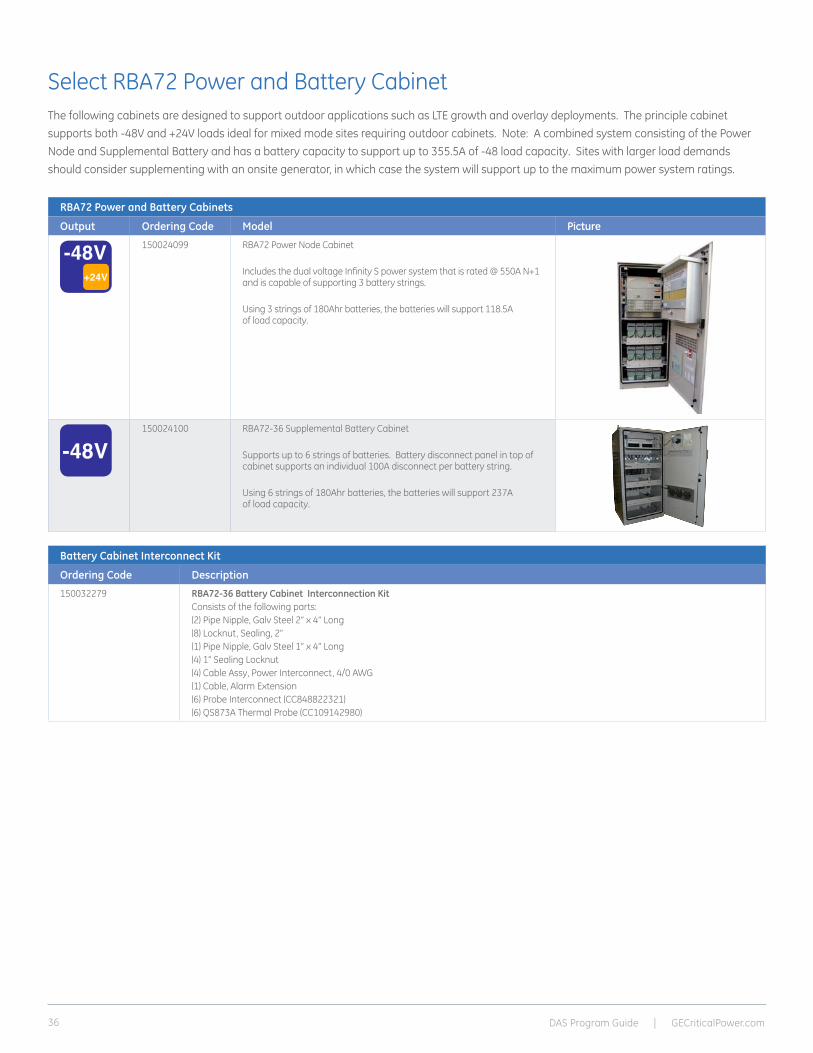
Select RBA72 Power and Battery CabinetThe following cabinets are designed to support outdoor applications such as LTE growth and overlay deployments. The principle cabinet supports both -48V and +24V loads ideal for mixed mode sites requiring outdoor cabinets. Note: A combined system consisting of the Power Node and Supplemental Battery and has a battery capacity to support up to 355.5A of -48 load capacity. Sites with larger load demands should consider supplementing with an onsite generator, in which case the system will support up to the maximum power system ratings.
RBA72 Power and Battery Cabinets
Output Ordering Code Model Picture
-48V+24V
150024099 RBA72 Power Node Cabinet
Includes the dual voltage Infinity S power system that is rated @ 550A N+1 and is capable of supporting 3 battery strings.
Using 3 strings of 180Ahr batteries, the batteries will support 118.5A of load capacity.
-48V150024100 RBA72-36 Supplemental Battery Cabinet
Supports up to 6 strings of batteries. Battery disconnect panel in top of cabinet supports an individual 100A disconnect per battery string.
Using 6 strings of 180Ahr batteries, the batteries will support 237A of load capacity.
Battery Cabinet Interconnect Kit
Ordering Code Description
150032279 RBA72-36 Battery Cabinet Interconnection KitConsists of the following parts:(2) Pipe Nipple, Galv Steel 2” x 4” Long(8) Locknut, Sealing, 2”(1) Pipe Nipple, Galv Steel 1” x 4” Long(4) 1” Sealing Locknut(4) Cable Assy, Power Interconnect, 4/0 AWG (1) Cable, Alarm Extension(6) Probe Interconnect (CC848822321)(6) QS873A Thermal Probe (CC109142980)

DAS Program Guide | GECriticalPower.com 37
Bay OptionsThe GPS4827 system can be deployed with capacity of up to 1800 amps in a single cabinet or expanded over multiple cabinets to 2700 amps. Designed for either internal input AC breakers or terminal strip terminations, rectifier shelves can be spread across two bays or concentrated to a single bay. In applications needing additional distribution, two more bays can be added and dedicated exclusively for distribution. For greater flexibility and working space, the GPS4827 may be equipped with a larger 36 inch wide distribution bay to accommodate large cable termination and egress.
Infinity Rectifiers The Infinity TE rectifier series offers modules for use in -48Vdc applications.
Galaxy Pulsar* Plus Controller As an economical alternative, the GPS4827 can be equipped with the Pulsar Controller. Designed to monitor and control system components including rectifier’s converters and distribution modules via a multi-drop RS485 digital communications bus. System status, parameters settings and alarm thresholds can be viewed and configured from the controller’s front panel or PC interface.
Features and Benefits
• Medium power applications utilizing single-phase or 3-phase 240Vac input
• Full featured control and monitoring capability
• 1800 Amp capacity per bay
• Efficiency approaching 97%
Reliability• Distributed fault tolerance
• Proven field performance
• Controller continuity
Intelligence• Industry leading controller features
• Ethernet interface for remote access
• Centralized network management
Investment Protection• Module compatibility
• Power shelf growth
• Flexible upgrade options
On Time Delivery• 4 – 6 week availability
• 24/7 technical support
• Standard building blocks
The GPS4827 capitalizes on the product strengths found in the GPS4848 and Infinity product families by integrating the high efficiency Infinity TE rectifier platform and the time-tested distribution found in the GPS4848. Utilizing the 1U 50A 48Vdc rectifiers, a fully equipped bay only requires 15.75 inches allowing for as much as 54 inches of distribution panels. With this increased density, a single bay GPS4827 system provides ampacity and distribution for most medium and small applications but retains all the features found with the larger GPS4848.
GPS 4827 Infinity Power System-48V DC Medium Power Plant

DAS Program Guide | GECriticalPower.com38
Cabinet SpecificationsMechanical
Height 84.0 inches (2,134mm)
Width 23.6 inches (600mm)
Depth 23.6 inches (600mm)
Thermal
12 Rectifiers 1,368W (4632 BTU/hr)
24 Rectifiers 2,736W (9264 BTU/hr)
36 Rectifiers 4,104W (13,896 BTU/hr)
Environmental
Operating Temperature Range 0°C to +45°C (32°F to 113°F)
Operating Relative Humidity < 95% non-condensing
Storage Temperature Range -40°C to +85°C (-40°F to 185°F)
EMC FCC and CISPR22 (EN55022) Class A
Immunity GR1089, EN55024
Agency Certifications
UL Canada/US UL60950/UL1801
EMI/EMC CISPR class B conducted and radiated
AC Input Specifications
FOR CODE
NAME PLATE RATING (INPUT CURRENT)
EXTERNAL BREAKER CONDUIT QTY & SIZE
WIRE SIZE (BASED ON WIRE RATED 75 C)
GROUND WIRE (BASED ON WIRE RATED 75 C)SIZE QTY
G026
12 AC FEED AT 15A EACH, 200 VAC 20A (12) 2-POLE 1 (2") (24) 8 AWG (1) 8 AWG
12 AC FEED AT 15A EACH, 200 VAC 20A (12) 2-POLE 2 (1.5") (24) 8 AWG (2) 8 AWG
12 AC FEED AT 15A EACH, 200 VAC 20A (12) 2-POLE 4 (1") (24) 10 AWG (4) 10 AWG
6 AC FEED AT 30A EACH, 200 VAC 40A (6) 2-POLE 2 (1") (12) 8 AWG (2) 8 AWG
G028
36 AC FEED AT 15A EACH, 200 VAC 20A (36) 2-POLE 4 (1.5") (72) 8 AWG (4) 8 AWG
36 AC FEED AT 15A EACH, 200 VAC 20A (36) 2-POLE 3 (2") (72) 8 AWG (3) 8 AWG
36 AC FEED AT 15A EACH, 200 VAC 20A (36) 2-POLE 9 (1") (72) 10 AWG (9) 10 AWG
18 AC FEED AT 30A EACH, 200 VAC 40A (18) 2-POLE 3 (2") (36) 4 AWG (3) 6 AWG
12 AC FEED AT 45A EACH, 200 VAC* 60A (12) 2-POLE 4 (1.5") (24) 4 AWG (4) 6 AWG
*Requires (8) CC408641204 AC Strapping Kits
DAS Program Guide | GECriticalPower.com 39
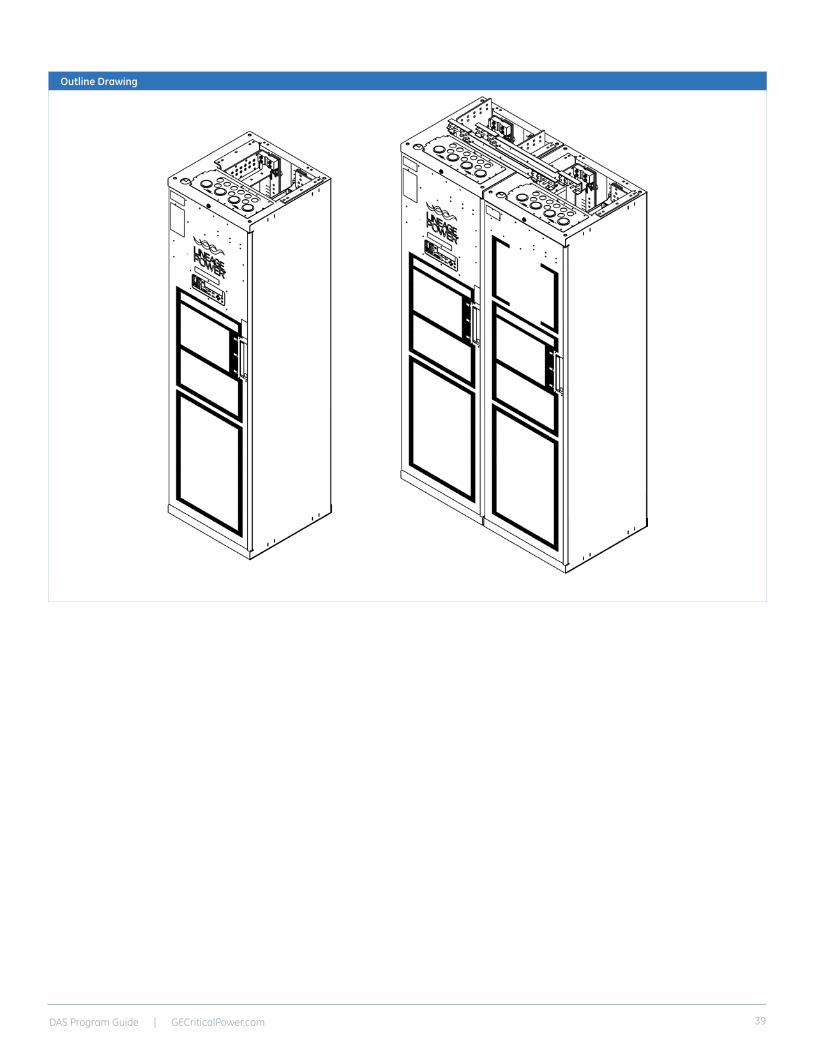
Outline Drawing
DAS Program Guide | GECriticalPower.com40
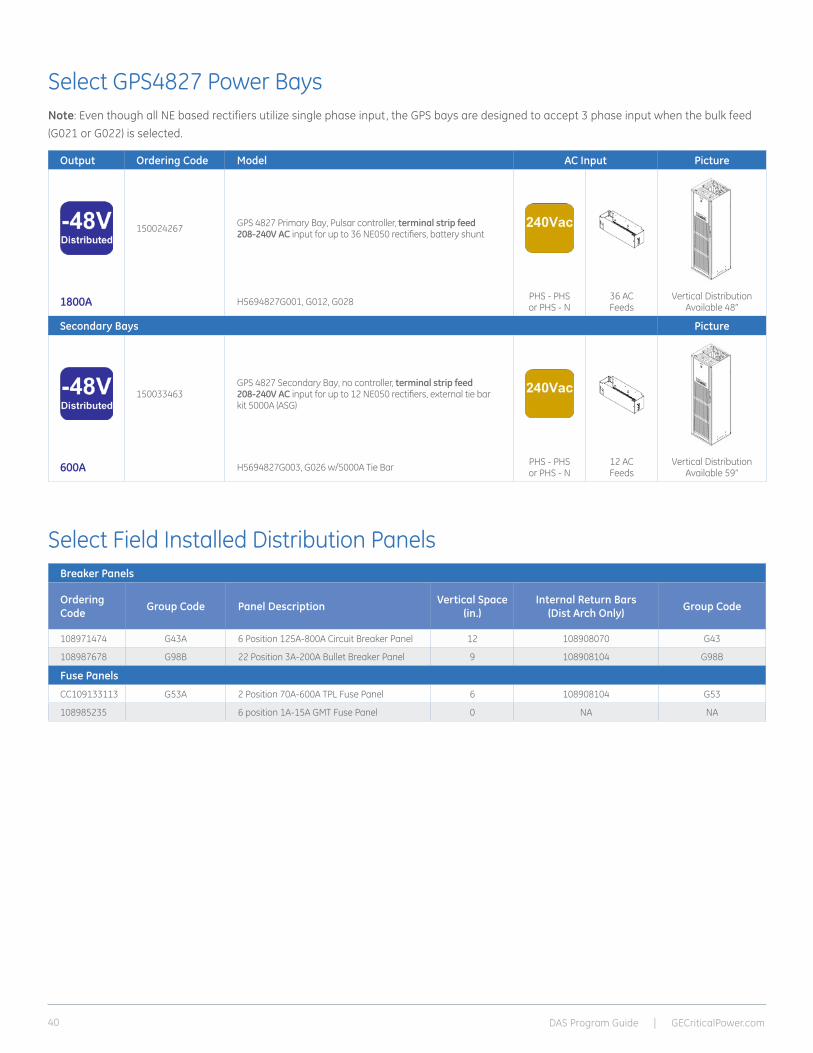
Select GPS4827 Power BaysNote: Even though all NE based rectifiers utilize single phase input, the GPS bays are designed to accept 3 phase input when the bulk feed (G021 or G022) is selected.
Output Ordering Code Model AC Input Picture
150024267 GPS 4827 Primary Bay, Pulsar controller, terminal strip feed 208-240V AC input for up to 36 NE050 rectifiers, battery shunt
1800A H5694827G001, G012, G028 PHS - PHS or PHS - N
36 AC Feeds
Vertical Distribution Available 48”
Secondary Bays Picture
150033463GPS 4827 Secondary Bay, no controller, terminal strip feed 208-240V AC input for up to 12 NE050 rectifiers, external tie bar kit 5000A (ASG)
600A H5694827G003, G026 w/5000A Tie Bar PHS - PHS or PHS - N
12 AC Feeds
Vertical Distribution Available 59”
Select Field Installed Distribution PanelsBreaker Panels
Ordering Code Group Code Panel Description Vertical Space
(in.)Internal Return Bars
(Dist Arch Only) Group Code
108971474 G43A 6 Position 125A-800A Circuit Breaker Panel 12 108908070 G43
108987678 G98B 22 Position 3A-200A Bullet Breaker Panel 9 108908104 G98B
Fuse Panels
CC109133113 G53A 2 Position 70A-600A TPL Fuse Panel 6 108908104 G53
108985235 6 position 1A-15A GMT Fuse Panel 0 NA NA

DAS Program Guide | GECriticalPower.com 41
Select Optional Return Bus BarsStandard Architecture 600mm Bays
Ordering Code Description
CC848805160 External Return Bus Kit: Option for termination of all distribution return cables. 1 per cabinet, rated at 1800 Amps. The external return bus kit is an alternative to internal return buses when many large cables are required.
Order optional termination bar if standard 8 positions may be exceeded
Ordering Code Description
850019233 Optional bus bar that provides 16 output terminations. (one required per cabinet)
Select Battery Termination Options
DAS Program Guide | GECriticalPower.com42
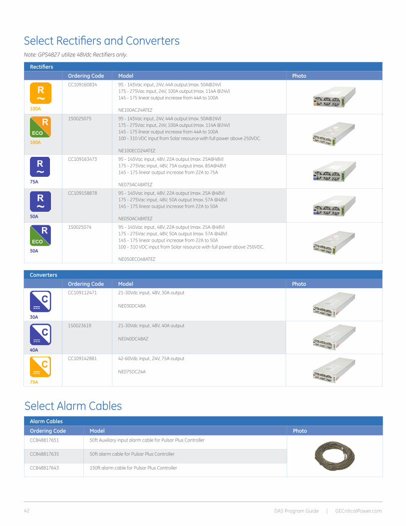
Select Rectifiers and ConvertersNote: GPS4827 utilize 48Vdc Rectifiers only.
Rectifiers
Ordering Code Model Photo
100A
CC109160834
95 - 145Vac input, 24V, 44A output (max. 50A@24V)175 - 275Vac input, 24V, 100A output (max. 114A @24V)145 - 175 linear output increase from 44A to 100A NE100AC24ATEZ
100A
150025075 95 - 145Vac input, 24V, 44A output (max. 50A@24V)175 - 275Vac input, 24V, 100A output (max. 114A @24V)145 - 175 linear output increase from 44A to 100A 100 - 310 VDC input from Solar resource with full power above 250VDC. NE100ECO24ATEZ
75A
CC109163473 95 - 145Vac input, 48V, 22A output (max. 25A@48V)175 - 275Vac input, 48V, 75A output (max. 85A@48V)145 - 175 linear output increase from 22A to 75A NE075AC48ATEZ
50A
CC109158878
95 - 145Vac input, 48V, 22A output (max. 25A @48V)175 - 275Vac input, 48V, 50A output (max. 57A @48V) 145 - 175 linear output increase from 22A to 50A NE050AC48ATEZ
50A
150025074 95 - 145Vac input, 48V, 22A output (max. 25A @48V)175 - 275Vac input, 48V, 50A output (max. 57A @48V) 145 - 175 linear output increase from 22A to 50A 100 - 310 VDC input from Solar resource with full power above 250VDC. NE050ECO48ATEZ
Converters
Ordering Code Model Photo
30A
CC109112471
21-30Vdc input, 48V, 30A output
NE030DC48A
40A
150023619 21-30Vdc input, 48V, 40A output
NE040DC48AZ
75A
CC109142881
42-60Vdc input, 24V, 75A output
NE075DC24A
Alarm Cables
Ordering Code Model Photo
CC848817651 50ft Auxiliary input alarm cable for Pulsar Plus Controller
CC848817635 50ft alarm cable for Pulsar Plus Controller
CC848817643 150ft alarm cable for Pulsar Plus Controller
Select Alarm Cables

DAS Program Guide | GECriticalPower.com 43
Select Distribution ComponentsNote: All systems support plug-in (bullet style) breakers or fuse modules. Larger breakers can be 2 or even 3 poles. The multi-pole breakers MUST be
used with the appropriate multi-pole adapter to parallel the poles for proper operation.
Bullet Style Load Circuit Breakers
Ordering Code Amperage CB Positions (Poles) Min Wire Gauge Photo407998137 3 1 10
407998145 5 1 10
407998152 10 1 10
407998160 15 1 10
407998178 16 1 10
407998186 20 1 10
407998194 25 1 10
407998202 30 1 10
408213486 40 1 8
407998210 45 1 8
407998228 50 1 6
407998236 60 1 6
407998244 70 1 2
407998251 80 1 2
407998269 90 1 2
407998277 100 1 2
CC848808551 100 2 2
408185353 125 2 2
408185346 150 2 1/0
408564941 200 3 2/0
CC408573975 225 3 4/0
408535752 250 3 4/0
CC848756916 2-pole Adapter bus for 100-150A breakers; used for ¼”-20 on 5/8” lugs (order 2 per 2 pole breaker to accommodate load and return lugs)Infinity M & S only
850021775 2-pole Adapter bus for 100-150A breakers; used for 3/8” on 1” lugs (order 2 per 2 pole breaker to accommodate load and return lugs)Infinity M & S only
CC848756924 3-pole Adapter bus for 200-250A breakers; off-center connection (order 2 per 3 pole breaker to accommodate load and return lugs)Infinity M & S only
850021955 3-pole Adapter bus for 200-250A breakers; centered connection (order 2 per 3 pole breaker to accommodate load and return lugs)Infinity M & S only
848631479 2-pole adapter bus kit (includes bus for ¼” hole lug on 5/8” centers and hardware), order one per breakerGPS 4827 only
848745662 3-pole adapter bus kit (includes bus for 5/16” hole lug on 1” centers and hardware), order one per breakerGPS 4827 only
Note: For 70-100A single pole breakers, one breaker space must be left open in the adjacent position when powering breaker above 80% capacity under normal loading conditions.
DAS Program Guide | GECriticalPower.com44
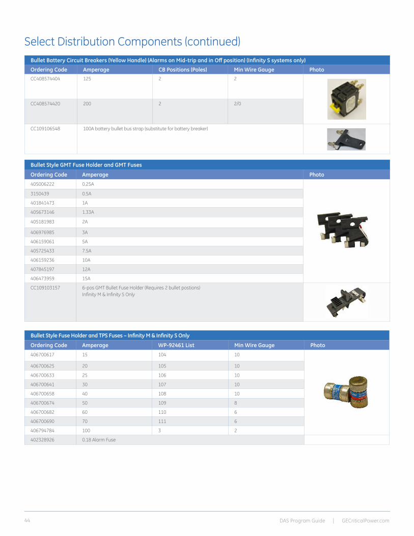
Select Distribution Components (continued)Bullet Battery Circuit Breakers (Yellow Handle) (Alarms on Mid-trip and in Off position) (Infinity S systems only)
Ordering Code Amperage CB Positions (Poles) Min Wire Gauge PhotoCC408574404 125 2 2
CC408574420 200 2 2/0
CC109106548 100A battery bullet bus strap (substitute for battery breaker)
Bullet Style GMT Fuse Holder and GMT Fuses
Ordering Code Amperage Photo
405006222 0.25A
3150439 0.5A
401841473 1A
405673146 1.33A
405181983 2A
406976985 3A
406159061 5A
405725433 7.5A
406159236 10A
407845197 12A
406473959 15A
CC109103157 6-pos GMT Bullet Fuse Holder (Requires 2 bullet postions)Infinity M & Infinity S Only
Bullet Style Fuse Holder and TPS Fuses – Infinity M & Infinity S Only
Ordering Code Amperage WP-92461 List Min Wire Gauge Photo
406700617 15 104 10
406700625 20 105 10
406700633 25 106 10
406700641 30 107 10
406700658 40 108 10
406700674 50 109 8
406700682 60 110 6
406700690 70 111 6
406794784 100 3 2
402328926 0.18 Alarm Fuse
DAS Program Guide | GECriticalPower.com 45
Select Distribution Components (continued)
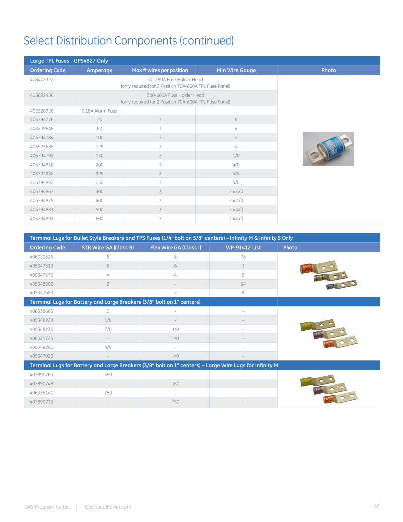
Terminal Lugs for Bullet Style Breakers and TPS Fuses (1/4” bolt on 5/8” centers) – Infinity M & Infinity S Only
Ordering Code STR Wire GA (Class B) Flex Wire GA (Class I) WP-91412 List Photo
406021626 8 8 75
405347519 6 6 3
405347576 4 4 5
405348202 2 - 54
405347683 - 2 8
Terminal Lugs for Battery and Large Breakers (3/8” bolt on 1” centers)
406338665 2 - -
405348228 1/0 - -
405348236 2/0 1/0 -
406021725 - 2/0 -
405348251 4/0 - -
405347923 - 4/0 -
Terminal Lugs for Battery and Large Breakers (3/8” bolt on 1” centers) – Large Wire Lugs for Infinity M
407890763 350 - -
407890748 - 350 -
406335141 750 - -
407890730 - 750 -
Large TPL Fuses - GPS4827 Only
Ordering Code Amperage Max # wires per position Min Wire Gauge Photo
408472322 70-250A Fuse Holder Head (only required for 2 Position 70A-600A TPL Fuse Panel)
406622456 300-600A Fuse Holder Head(only required for 2 Position 70A-600A TPL Fuse Panel)
402328926 0.18A Alarm Fuse
406794776 70 3 6
408239648 80 3 4
406794784 100 3 2
406925685 125 3 2
406794792 150 3 1/0
406794818 200 3 4/0
406794982 225 3 4/0
406794842 250 3 4/0
406794867 300 3 2 x 4/0
406794875 400 3 2 x 4/0
406794883 500 3 2 x 4/0
406794891 600 3 3 x 4/0
DAS Program Guide | GECriticalPower.com46
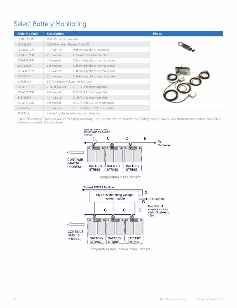
Select Battery MonitoringOrdering Code Description Photo
CC109142980 QS873A Thermal Probe (A)
150026698 QS873B Ambient Thermal Probe (A)
CC848817024 10 ft wire set (B: thermal probe to controller)
CC109157434 20 ft wire set (B:thermal probe to controller)
CC848822560 1 ft wire set (C: thermal probe to thermal probe)
848719803 5 ft wire set (C: thermal probe to thermal probe)
CC848822321 10 ft wire set (C: thermal probe to thermal probe)
850027334 20 ft wire set (C: thermal probe to thermal probe)
108958422 ES771A Battery Voltage Monitor Card
CC848791517 2-1/2 ft wire set (D: ES771A to thermal probe)
CC848797290 6 ft wire set (D: ES771A to thermal probe)
848719829 10 ft wire set (D: ES771A to thermal probe)
CC848791500 4 ft wire set (G: ES771A to ES771A or controller)
848652947 10 ft wire set (G: ES771A to ES771A or controller)
555052-1 In-Line Coupler (for extending item G above)
Temperature/Voltage probes are needed for battery monitoring. They are connected to each battery or battery string to provide slope thermal compensation, temperature alarms and voltage imbalance alarms.
Temperature Measurement
Temperature and Voltage Measurement

DAS Program Guide | GECriticalPower.com 47
Select Mounting Frame, Battery Trays, Installation KitNote: For Power Systems that are configured WITHOUT a mounting frame and/or battery trays.
Ordering Code Description Picture
150029836 Battery Frame 48V; 5 trays with 200A breakers
150029837 Battery Frame 24V; 5 trays with 200A breakers
150029839 Battery Frame 48V; 3 trays with 200A breakers Battery shelves, breaker kits, and DC cables with connectors. Does not include the power system or frame.
Infinity System shown for reference
150029840 Battery Frame 24V; 3 trays with 200A breakers Battery shelves, breaker kits, and DC cables with connectors. Does not include the power system or frame.
Infinity System shown for reference
CC848828938 7ft high relay rack for mounting 23” wide equipment(Zone 4 to 1800 lbs.)
CC848842955 23” Battery Tray (22” Depth) Typically Batteries include: East Penn (12A150FT, 12A170FT) Enersys (12V155FS, 12V170F) NorthStar (NSB110FT, NSB170FT)
CC408627533 Infinity Power System Cable and Installation KitFor use with the Infinity M & Infinity D Systems

601 Shiloh Road, Plano, TX 75074+1 877 546 3243 (toll-free in North America)+1 972 244 9288 (direct number)[email protected] GECriticalPower.com
24/7 Technical Support
CPB-DAS, Rev. 06/14 *Trademark of General Electric Company. Copyright 2014 General Electric Company. All Rights Reserved.
GE reserves the right to make changes to specifications of products described at any time without notice and without obligation to notify any person of such changes.
Management VisibilityGalaxy Manager* software is the centralized visibility and control component of a comprehensive power management system designed to meet engineering, operations and maintenance needs. The Galaxy Manager client-server architecture enables remote access to system controllers across the power network.
• Dashboard display with one-click access to management information database
• Trend analysis
• Scheduled or on demand reports
• Fault, configuration, asset, and performance management
TrainingGE offers on-site and classroom training options based on certification curriculum. Technical training can be tailored to individual customer needs. Training enables customers and partners to more effectively manage and support the power infrastructure. We have built our training program on practical learning objectives that are relevant to specific technologies or infrastructure design objectives.
Service & SupportGE field service and support personnel are trusted advisors to our customers – always available to answer questions and help with any project, large or small. Our certified professional services team consists of experts in every aspect of power conversion with the resources and experience to handle large turnkey projects along with custom approaches to complex challenges. Proven systems engineering and installation best practices are designed to safely deliver results that exceed our customers’ expectations.
WarrantyGE is committed to providing quality products and solutions. We have developed a comprehensive warranty that protects you and provides a simple way to get your products repaired or replaced as soon as possible.
For full warranty terms and conditions please go to www.gecriticalpower.com.