data acquisition · 6 rf-linked data acquisition eliminates the obstacles to gathering data with...
TRANSCRIPT

Data AcquisitionPortable, Wireless, Networked
The complete picturein data acquisition

2
Shared features
While their applications vary,all three product lines share anumber of unique features.
Unique built-in signal condi-tioning saves time and moneyFluke’s data acquisition productsare the first to integrate signalconditioning directly into theinstrument. You can assignany measurement function—thermocouple, RTD, volts,frequency, or ohms—to any orall channels.
Removable Universal InputModule connects any signalThe key to the flexibility of allFluke data acquisition products isour unique, patented UniversalInput Module that allows you toconnect and measure virtually anyelectrical or physical parameter.
Thermocouple referencejunction compensation occursautomatically by sensing thetemperature of the input module’sisothermal block.
Virtually any combination ofsensor or signal lines may beconnected to the input modulewhich is plugged into the backof the data acquisition unit. Youcan pre-wire extra input modulesat each test site and move yourdata acquisition units from onelocation to another.
Portable, wireless,and networked dataacquisition
Fluke offers three types of dataacquisition tools representingthree ways to transfer data.
Getting accurate data whereyou want it, when you wantit, and in a form that you canwork with is a universal goal.That’s true whether you’redesigning airplanes or automo-biles; manufacturing steel orprocessing chemicals. Foraccurate, reliable, quick dataacquisition, Fluke is thecommon denominator.
Fluke data acquisition prod-ucts feature unique built-inuniversal signal conditioningand a plug-in Universal InputModule to provide enormousflexibility. This allows you toaccurately measure a widerange of parameters simultane-ously without the expense orinconvenience of additionalequipment.
Powerful, easy-to-useWindows® -based softwaresupports easy configuration,advanced trend analysis, andprofessional-quality reporting,without any programming.
Hydra Series
The portable Hydra Seriestransfers data either to internalmemory (Hydra Data Logger), toa removable memory card (HydraData Bucket), or directly to yourPC (Hydra Data Acquisition Unit).
Wireless Logger™
The go-anywhere WirelessLogger™ transfers data in real timevia a secure RF link to a wirelessmodem connected to your PC.Its wireless design enables it totransmit through buildings, walls,and floors and makes it conve-nient for remote locations. It alsosaves the expense of cabling inany location.
NetDAQ®
Distributed NetDAQ units plugright into your existing networksto send data directly to a PC.This saves the cost of setting up anew network and allows multipleusers to simultaneously viewdata in real time. NetDAQ unitscan also be used as a portablededicated system connected toa notebook computer for mainte-nance, product validation, research,and troubleshooting applications.
Fluke’s Family of Data Acquisition Products
+ –
3
Thermocouple
AC Current
AC Voltage
DC Current
DC Volt
POT.
RTD
Frequency
Ohms
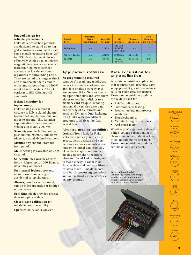
Universal MaxModel Signal Basic DC PC Channels ReadingSeries Conditioning Accuracy Interface Per System Rate (Rdgs/s)
RS-232Hydra Series Yes 0.018% PCMCIA 21 to 42 17
IEEE-488
Wireless Logger Yes 0.018% RF Modem 21 to 420 17
NetDAQ Yes 0.01% Ethernet 20 to 400 1000(TCP/IP)
Rugged design forreliable performanceFluke data acquisition productsare designed to stand up to rug-ged industrial environments withsome models operating from -20°to 60°C. A sturdy metal chassiseffectively shields against electro-magnetic interference so you canmaintain high measurementaccuracy on low-level signalsregardless of surrounding noise.They are tested to stringent shockand vibration standards and towithstand surges of up to 1500Vinput on most models. All unitsconform to IEC, CSA, and CEstandards.
Isolated circuitry fortop accuracyFluke analog measurementcircuitry is fully isolated channel-to-channel, input-to-output, andinput-to-ground. This isolationsupports direct measurement ofvoltages up to 300V AC rms.Scan triggers, including interval,push button, external, and alarmtriggers, scan all defined channels.Monitor any channel from thefront panel.Mx+B scaling is available on eachchannel.Selectable measurement ratesfrom 4 Rdgs/s up to 1000 Rdgs/s,depending on model.Front panel lockout preventsunauthorized tampering oraccidental setup changes.Alarms, two for each channel,can be independently set for highor low sense.Real time clock provides precisetime stamping of data.Closed-case calibration forreliability and traceability.Operates on AC or DC power.
Application software
No programming requiredWindows®-based logger softwaremakes instrument configurationand data analysis as easy as afew mouse clicks. You can createmultiple setup files and save themeither to your hard disk or to amemory card for quick reconfig-uration. You can also save datain a variety of file formats andestablish Dynamic Data Exchange(DDE) links with spreadsheetprograms to analyze the datain real time.
Advanced trending capabilitiesOptional Trend Link for Flukesoftware enables you to easilyaccess, view, analyze and com-pare tremendous amounts of realtime or historical data from anyFluke data acquisition product,making paper chart recordersobsolete. Trend Link is designedto make it easy to zoom in ondata, review and compare histori-cal data to real-time data, com-pare batch processing operations,and automatically view statisticson any channel.
Universal Input ModuleConnect any sensor type or inputsignal to any channel—internalsignal conditioning automaticallyswitches to correct function.
Data acquisition forany application
Any data acquisition applicationthat requires high accuracy, easysetup, portability, and conveniencecalls for Fluke data acquisition.Fluke data acquisition productsare widely used for:
• R & D applications.• Environmental testing.• Product testing and process
validation.• Troubleshooting.• Manufacturing test systems.• And much more.Whether you’re gathering data ata high-voltage substation, in aclean room, on a production line,or on an automotive test track,Fluke data acquisition productscan make your job easier.

4
Portable, flexiblesolutions for stand-alone or PC-baseddata acquisition
The Hydra Series offers easyportability along with Fluke’sbuilt-in signal conditioning andUniversal Input Module at aprice to fit your budget. You caneasily retrieve data from theHydra units via the RS-232interface, or through a modemin upload or real-time mode.
Channel information andmeasurement parameters canbe set up directly from the frontpanel or your PC.
Three models featuringremovable memory card datastorage, internal memorystorage, and direct real-timedata transfer options.
Should power fail, theseinstruments automaticallyresume data collection whenpower is restored.
2635A HydraData Bucket
The ideal choice for gatheringand transporting large volumesof data and for working extendedperiods from remote locations.
FlexibilityThe Hydra Data Bucket comesequipped with a 256 KB PCMCIAcard and is also available witheither a 1 MB, 2 MB, or 4 MBmemory card to suit your datastorage needs. Data may be up-loaded from these cards via theHydra RS-232 port, the optional263XA-803 memory card drive,or from your computer’s standardPCMCIA slot. Real-time data canbe simultaneously transferred to aPC at the same time it is recordedto the memory card.
Quick setupsSimply push a few front panelbuttons or load instrument setupsfrom the memory card.
Fail-safe featuresThe Hydra Data Bucket givesadvance indication of a lowbattery or low memory conditionon the memory card. Its internalmemory buffer continues to storeup to 70 scans while the card isremoved.
2625A HydraData Logger
A low-cost alternative for stand-alone monitoring operations.
Internal memoryA built-in nonvolatile memorythat can store more than 2000scans.
Flexible data retrievalThe ability to upload stored dataor transfer real-time datavia modem, or directly to yourPC via the RS-232 port.
2620A Hydra DataAcquisition Unit
Hydra is ideal for applicationsthat require direct connection toa PC for real-time data collection.
Easy-to-use front-endAn RS-232 serial interface makesit easy to connect the Hydra DataAcquisition Unit to a PC or modemfor real-time data acquisition.The 2620A can also be used asa 20-channel panel meter.
IEEE interfaceAn optional IEEE-488 interfaceeasily allows you to integratethe 2620A with other IEEE-488instruments and your PC. The2620A delivers workhorseperformance for a wide varietyof applications such as test andmonitoring systems.
Hydra Series

5
Menu-driven softwaresimplifies setup
Optional Hydra Logger softwareprovides an intuitive graphicalinterface that makes it eveneasier to configure and accessyour Hydra unit’s powerful fea-tures without any programming.
2620A Hydra Data Acquisition Unit2620A/05 Hydra Data Acquisition Unit with
IEEE-488 interface2625A Hydra Data Logger2635A Hydra Data Bucket (256 KB
memory card)2635A-1MB Hydra Data Bucket
(1 MB memory card)2635A-2MB Hydra Data Bucket
(2 MB memory card)2635A-4MB Hydra Data Bucket
(4 MB memory card)Includes: Instrument, Universal Input Module, linecord, user manual, Starter Software (DOS)
Options and accessories2620A-100 Extra Universal Input Module263XA-803 External PC Memory Card
Drive263XA-804 Memory Card-256 KB263XA-805 Memory Card-1 MB263XA-806 Memory Card-2 MB263XA-807 Memory Card-4 MBRS43 RS-232 cable; (DB9 to DB9),
Hydra to PC; 1.8m26XXA-600 Hydra Portable Battery Pack2620A-101 Current Shunt, 10Ω, for 0 to
100 mA, Qty (12)M00-200-634 19" Rack Mount KitY8021 Shielded IEEE-488 Cable,
1 MeterP/N 889589 Service ManualC40 Hydra Carrying CaseC44 Transit Case
Application software2635A-901 Hydra Logger2635A-902 Hydra Logger with Trending2600A-904 Trend Link for Fluke
Ordering information
Hydra Series features
• Review the min/max and lastreadings from the front panel
• Channel 0 accepts standardtest leads from the front panelfor quick measurements
• Monitor a selected channelfrom the front panel.
• Use the Channel Function toconfigure measurement typeand range for each individualchannel
• Use the Memory Card Drive (in2635A only) to store data andinstrument configuration on aportable, non-volatile memorycard and transfer collecteddata to your PC for lateranalysis
Easy portability and quick configuration forconvenient field use.
UniversalSignal Nonvolatile
Model Conditioning Data Storage Interface
2635A Data Bucket Yes PCMCIA Card RS-232
2625A Data Logger Yes Internal RS-232
2620A Data Acquisition Unit Yes None RS-232
2620A/05 Data Acquisition Unit Yes None IEEE-488

6
RF-linked dataacquisition eliminatesthe obstacles togathering data
With the Fluke Wireless Logger,you can collect and transmitdata via a secure RF link fromvirtually any location—no matterhow inaccessible—without theexpense or hassle of runningcable long distances.
Spread spectrumRF technology clearsthe way
Unlike traditional narrow band RFtransmission that is susceptible toelectromagnetic interference, thespread spectrum technology usedin the Wireless Logger is ideal inareas where narrow band equip-ment fails. It was developed formilitary communications systemsrequiring exceptional immunity toelectromagnetic interference andhigh data transmission integrity.This means you won’t have toworry about motors, solenoids,walkie-talkies, and other sourcesof severe electrical interferenceinterrupting your transmissions.It transmits up to 120 metersthrough walls and floors, or up to300 meters in line-of-sight appli-cations using the modem.
This technology also allowsthe Wireless Logger to coexistwith other electronic equipment.Its power output is lower thancellular phones. The spreadingtechniques and frequency dwelltimes used by the WirelessLogger modems produce an
effective peak power at anyfrequency that is lower thanequivalent narrow band trans-mission—too low to disrupt orinterfere with other electronicinstrumentation. And, it complieswith FCC part 15C and does notrequire an FCC site license. Theoptional 2.4 GHz modem is ETSIcertified for operation in mostEuropean and many othercountries.
Saves on hazardous dutyThe Wireless Logger thrives ontough jobs that would put peopleat risk. Whether it’s placed atthe top of a smokestack, or sur-rounded by toxic materials, highvoltage, or exhaust fumes, theFluke Wireless Logger is quick toset up and can take the heat.
Fault tolerance preventsdata lossEach Wireless Logger satellitecan store more than 2000 scansin its nonvolatile buffer. If your PCgoes down during data acquisi-tion, the Wireless Logger satellitecontinues to collect measure-ments. When your PC comes backon line, the data collected in theinterim can be transferred to yourdata file automatically.
The Wireless Logger satelliteconsists of a Hydra Data Logger(2625A) and a 2.4 GHz wirelessmodem, both housed in a pro-tective soft-sided carrying case.Built-in signal conditioningeliminates the need to addadditional components forsignal or sensor interfacing.
Back at the office, attachthe wireless base stationmodem to the RS-232 porton your PC, install WirelessLogger for Windows software,transmit your setup informa-tion and you’re ready to startcollecting data.
Wireless Logger™

7
Ordering information
Wireless Logger™
features
• No cables to run or maintain• Up to 300m range• Spread spectrum technology
provides exceptional immunityto electromagnetic interference,high-data transmission integ-rity, and security
• Site-Survey capability enablesone person to set up satellitesand verify communication tothe base station
• High fault tolerance to continuerecording data if PC goes down
• Supports up to 20 units for atotal of 420 channels
Base StationReal-time data collection from up to 20Wireless Logger satellites using theWireless Logger Base Station.
2625A/W2 Wireless Logger(2.4 GHz) Includes: 2625A Hydra
Data Logger system, one(2.4 GHz, FCC; ETSI certified)wireless modem with powermodule, C42 Carrying Case,manual
2625A/W2-700 Wireless Logger Base Station(2.4 GHz) Includes: One wireless
modem (2.4 GHz, FCC; ETSIcertified), Wireless Loggerfor Windows software,cables, manual
Options and accessories26X5A/W2-701 Hydra Wireless(2.4 GHz) Conversion Kit
Includes: (2.4 GHz) wirelessmodem with power module,C42 Carrying Case (used toconvert 2625A or 2635A towireless operation)
26XXA-705 Wireless Logger PortableBattery PackIncludes: Charger, carryingcase, modem power module,connector cable, battery(6.5 Ah@ 12V)
C42 Wireless Logger CarryingCase
C44 Transit Case2620A-100 Extra Universal Input Module2620A-101 Current Shunts, 10Ω, for
0-100 mA, Qty (12)
Range (line-of-sight/Basic System Channel Capacity Interface indoors, typical)
2625A/W2 300m(Satellite) RF Modem
and 21 to 420 (Spread Spectrum)26X5A/W2-700 (2.4 GHz) 120m(Base Station)
Windows®-basedsoftware extendsversatile performance
Wireless Logger for Windowssoftware makes it easy to config-ure and communicate with up to20 Wireless Logger satellites atthe same time through a singlespread spectrum modem con-nected to your PC. And you canshare that data with spreadsheetprograms in real time.
Easy to set up and verifyA wireless base station thatincludes Wireless Logger soft-ware, base station modem, and aWireless Logger satellite are allyou need to start collecting data.
Its unique Site-Survey featuremakes it easy for one person toset up satellites and verify com-munication between the satelliteand the base station.
8
Delivers versatilesolutions for distrib-uted data acquisition
Fluke NetDAQ networked dataacquisition units are a powerfulcombination of hardware andsoftware seamlessly integratedto deliver your data directly overyour network. These systems,with Trend Link software, en-able multiple users to view onlythe information they need inreal time, from anywhere on thesystem. View current, tempera-ture, voltage, and more on thesame screen at the same time.You can also monitor severalunits simultaneously making itideal for applications such asequipment monitoring, producttesting, and process validation.NetDAQ replaces aging chartrecorders and adds futureexpandability to your measure-ment system.
You can combine from one totwenty NetDAQs into an inte-grated NetDAQ system of up to400 channels. Use an existingnetwork or simply connectdirectly to your PC. Two modelsoffer a choice of scan speeds (upto 1000 Rdgs/s), and accuracy(up to 0.01%) to meet your needs.
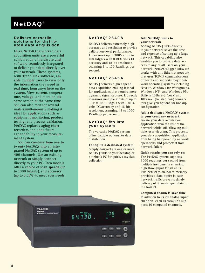
NetDAQ® 2640A
NetDAQ delivers extremely highaccuracy and resolution to providecalibration-level performance.It measures up to 300V at up to100 Rdgs/s with 0.01% volts DCaccuracy and 18-bit resolution,scanning 6 to 100 Readings persecond.
NetDAQ® 2645A
NetDAQ delivers higher speeddata acquisition making it idealfor applications that require moredynamic signal capture. It directlymeasures multiple inputs of up to50V at 1000 Rdgs/s with 0.01%volts DC accuracy and 16-bitresolution, scanning 48 to 1000Readings per second.
NetDAQ® fits intoyour system
The versatile NetDAQ systemoffers flexible options for datadistribution.
Configure a dedicated systemSimply daisy-chain one or moreNetDAQ units to your desktop ornotebook PC for quick, easy datacollection.
Add NetDAQ® units toyour networkAdding NetDAQ units directlyto your network saves the timeand expense of setting up a largenetwork. This capability alsoenables you to provide data ac-cess to any or all users on yournetwork. NetDAQ Logger softwareworks with any Ethernet networkthat uses TCP/IP communicationsprotocol and supports major net-work operating systems includingNovell®, Windows for Workgroups,Windows NT®, and Windows 95.Built-in 10Base-2 (coax) and10Base-T (twisted pair) connec-tors give you options for hookupconfiguration.
Add a dedicated NetDAQ® systemto your company networkIsolate your data acquisitionapplication from the rest of thenetwork while still allowing mul-tiple-user viewing. This preventsyour data acquisition applicationfrom being hampered by networkoperations and protects it fromnetwork failure.
Quick results you can rely onThe NetDAQ system supports3000 readings per second frommultiple instruments ensuringhigh throughput for all units.Plus NetDAQ’s on-board memoryprovides a data buffer in casenetwork traffic prevents timelydelivery of time-stamped data tothe host PC.
Computed channels save timeIn addition to its 20 analog inputchannels, each NetDAQ unit sup-ports 10 computed channels.
NetDAQ®

9
Ordering information
Reading/sec Resolution Max. Input Basic TCModel (Max) (Volts DC) (Volts DC) Accuracy (Type T)
2640A 100 0.3 mV 150/300* 0.3ºC
2645A 1000 3.0 mV 50 0.7ºC
It performs custom calculationsusing addition, subtraction, multi-plication, division, log, naturallog, exponent, square root, abso-lute value, and integer functions.Math channels have the samealarm capability as analog chan-nels. This saves the time of per-forming separate post calculationson channel data and is especiallyhelpful for monitoring and alarm-ing on real time calculated valuessuch as power, flow, volumes,pressure, and more.
NetDAQ® Logger andoptional trendingsoftware keep youon top of the situation
The highly intuitive NetDAQLogger software makes it easy toset up and configure up to 20NetDAQs. Combining NetDAQLogger software with Fluke’soptional trending software en-ables multiple users to easilymonitor processes and importdata into spreadsheet programsfor further analysis. This providesmore efficient operation andimproved productivity.
NetDAQ Logger software sup-ports up to 400 channels andoffers a choice of English, French,Spanish, or German duringinstallation.
Developer’s Toolbox forsystem integrationFluke offers an optional NetDAQDeveloper’s Toolbox to allowprogrammers and developers toautomate and customize NetDAQoperation using Visual Basic, C orC++ programming languages.
It includes a set of routines whichmanipulate NetDAQ measurementhardware through NetDAQ Loggerfor Windows software allowingyou to:
• Create custom user interfacesfor NetDAQ applications.
• Access real time data and storeit in any format, such as acustom database.
• Automatically load differentsetup files.
• Change Mx+B values for eachchannel on an instrument.
• Control digital I/O channels.• Access and control NetDAQ’s
serial port.
NetDAQ® features
• Expandable systems from 20 to400 channels
• High accuracy readings, up to0.01%
• Higher throughput, to supportup to 3000 readings per second
• Distributed design enablesmultiple users, equipped withTrend Link software, to viewtrend data at the same time
• Network flexibility enables youto add to your existing networkor set up as a dedicated system
*300V max for channels 1, 11; all others 150V
2640A NetDAQ Data Acquisition Unit(100 Rdgs/s)
2645A NetDAQ Data Acquisition Unit(1000 Rdgs/s)
Includes: Instrument, Universal Input Module,4m Coax cable, 50Ω terminator, Y BNCadapter, power cable. (User manual includedwith NetDAQ Logger software.)
Application software2640A-911 NetDAQ Logger2640A-912 NetDAQ Logger with Trend Link2600A-904 Trend Link for Fluke264XA-903 Developer’s Toolbox
Options and accessories264XA-801 Ethernet Card (10Base-2,
10Base-T) PC plug-in264XA-802 Parallel-to-LAN Adapter
(10Base-2)264XA-803 PCMCIA-to-LAN Adapter
(10Base-2, 10Base-T)2620A-100 Extra Universal Input Module2620A-101 Current Shunts, 10Ω, for
0 to 100 mA, Qty (12)Y2641 19” Rack Mount Kit, single/dualY2642 Wall/Cabinet Mounting PlateY2644 NEMA 4X (IP65) EnclosureC44 Transit Case
A system of up to 400 channelscan be configured by “daisy-chaining”multiple NetDAQ units to one PC.

10
Puts your data to work
Fluke offers logger software forall our data acquisition units.These Windows®-based pro-grams turn your PC into a pow-erful tool for data acquisition,without any programming.They support:
• Configuration of signalconditioning for sensors andsignals connected to theUniversal Input Module.
• Data logging functions likeintervals, triggering, alarms,signal scaling and engineer-ing units.
• Easy data exchange byrecording data in a file formatthat’s easily imported intoother applications such asspreadsheets.
• Dynamic Data Exchange(DDE) allows you to establishlinks for sharing data in realtime with Windows-basedspreadsheet programs suchas Microsoft Excel, Lotus1-2-3, and InTouch byWonderWare. Data is updatedevery second.
Hydra Loggersoftware
Hydra Logger software provideseasy access to all the powerfulfeatures in the Hydra Series.
• Access one or two Hydrainstruments at one time viaRS-232
• Establish modem commun-ications for remote dataacquisition
• Convert files to .CSV or TrendLink formats
• Copy files from a Data Bucketmemory card to the PC
• Store Data Bucket configura-tions on a memory card foreasy one-step field setup
Wireless Logger™ forWindows software
This easy-to-use softwareenables you to communicate toWireless Logger satellites througha single spread spectrum modemconnected to your PC.• Configure remote communica-
tions with up to 420 channels(20 Wireless Loggers)
• Site Survey feature helpsdetermine working distance
• Set software to alert you toalarm events at your PC
NetDAQ® Loggersoftware
NetDAQ Logger software allowsyou to easily configure andreconfigure your system and viewyour data.• Set up multiple NetDAQ units
(up to 20), distributed through-out your facility in a groupedmode to create a “virtualinstrument” that synchronizesand directs all data to a singledata file
• Save valuable disk space byrecording only readings out-side the range of your normalprocess limits
• Easy network configuration• Advanced triggering modes• File rollover feature automati-
cally creates a new data file ata specific time or size
All logger software features point-and-click configuration dialogs.
Data Logging Software

11
Trend Link for Flukesoftware
Combine easy analysis andreporting with Trend Link forFluke software. Trend Link forFluke software is a comprehen-sive trend plotting, batching, andanalysis package. It combines thelook and feel of a chart recorderwith the analytical power of yourPC. Trend Link software is avail-able for the full line of Fluke dataacquisition instruments—HydraSeries, Wireless Logger, andNetDAQ.
• Review real-time data inthe context of historical datafor performance or batchcomparisons
• Compare multiple channelsfrom different time periods
• Zoom in on a particular timespan for closer analysis
• View multiple windows—eachfeaturing different processparameters—in real time
• Calculate basic statistics suchas mean and standard devia-tion for any trend
• Create X-bar R charts and X-Yscatter diagrams for statisticalanalysis
• Import data directly intospreadsheet programs fromtrend plots
• Attach text notes to any pointon a trace that become part ofa permanent record
Quickly find specific dataTrend Link enables you to quicklyscroll through volumes of histori-cal and real-time data looking forkey events or changes in theprocess. When you find whatyou’re looking for, you can com-pare multiple traces against eachother on the same screen or zoomin on a particular point in time.
Document your resultsThe data and trend plots yougenerate with Trend Link soft-ware can be easily cut and pastedinto spreadsheet and word pro-cessing programs to generatepresentation-quality reports. Oryou can print plots directly forhard copy documentation.
1 Programs will automatically install the appropriate 16- or 32-bit software based on the residentoperating system (Windows 3.1, Windows 95, or Windows NT) at time of installation.
2 Language support for English, French, Spanish and German.
Data logging software availability chart
Control bar provides fast,easy access to basicchart functions.
Alarm shading gives avisual indication ofalarm point violation.
Main cursor bar undermouse control.
Displays value andtime at main cursorintersection.
Curve status windowoffers detailed curveinformation.
Statistical process controlfunction generates upper/lower control limits.
Notation system attachesyour comments as apermanent part of the record.
Instrument Model
Application Software 2620A 2620A/05 2625A 2635A 2625A/WL 2640A 2645A
Hydra Logger2• • •2635A-901
Hydra Logger with • • •Trend Link2 2635A-902
Wireless Logger •26X5A/WL-902
NetDAQ Logger1,2• •2640A-911
NetDAQ Logger with • •Trend Link1,2 2640A-912
Trend Link for Fluke1,2• • • • • •2600A-904
Developer’s Tool Box • •264XA-903

12
• Universal Input Module:Connect 20 analog inputsof virtually any sensor typewithout external signalconditioning
• Hydra Interfacing: UseRS-232 interface to connectto printer, PC or modem
• External Trigger: Activatescanning with real-worldevents
• Totalizer: Count on/off events,updated at every scan
• Alarm Outputs: Flag out-of-limit conditions to externaldevices
• Power: Accepts 90-264V AC,or 9-16V DC. Can operatefrom both simultaneously
Hydra Series andWireless Logger™
Channel capacityAnalog inputs: 21Digital I/0 and alarm outputs: 12 totalTotalizer: 1
Measurement rateSlow: 4 Rdgs/s nominalFast: 17 Rdgs/s nominal(1.5 Rdgs/s for V AC, Hz and Ω inputsnominal)
Analog to digital converterDual slope type, linear to 17 bits
Common mode rejectionAC: ≥120 dB (50/60 Hz, ±0.1% max 1 kΩsource imbalance); dc: ≥120 dB
Normal mode rejection53 dB (60 Hz, ±0.1%)47 dB (50 Hz, ±0.1%)
Common mode and normal modevoltage maximum300V DC or V AC rms (channels 0,1,11)150V DC or V AC rms (all other inputs)
IsolationAnalog input to analog input, and analoginput to any digital input: meets IEC1010 for 300/150 volts reinforced andANSI/ISA-S82.01-1994 and CSA-C22.2for 250 volts single insulation
Current measurementsAC or DC current measurements up to100 mA may be accomplished using the2620A-101 10Ω Current Shunt Strip
Hydra/Wireless Logger™ Specifications
Totalizing inputDC coupled, non-isolated, max +30V,min -4VMax count: 65,535Minimum signal: 2V peakThreshold: 1.4VRate: 0-5 kHz (debounce off)Hysteresis: 500 mVInput debouncing: None or 1.66 ms
Digital inputsThreshold: 1.4VHysteresis: 500 mVMaximum Input: +30V, min -4V;non-isolated
Digital/alarm outputsThe open collector output lines are non-isolated, TTL compatible
Alarms associationsAlarm outputs 0-3 are fixed assignmentsassociated to channels 0-3. Alarms forchannels 4-19 are mapped to digital I/Olines. Digital I/O may be used as a digitalinput or alarm status output (associatedwith any input channel or channels).
Trigger inputMinimum pulse: 5 µsMaximum latency: 100 msRepeatability: 1 msInput “High”: 2.0V min, 7.0V maxInput “Low”: -0.6V min, 0.8V maxnon-isolated, contact closure and TTLcompatible
ClockAccurate to within 1 minute/month for0 to 50°C range
Power90 to 264V AC 50 or 60 Hz (<10 watts),or 9 to 16V DC (<4 watts). (If bothsources are applied simultaneously, thegreater of AC or DC is used.) At 120V ACthe equivalent dc voltage ~14.5V.
Temperature, humidity(non-condensing)Operating:0 to 28°C, ≤90% RH28 to 40°C, ≤75% RH40 to 60°C, ≤50% RHStorage: -40 to 75°C, 5 to 95% RH
Electromagnetic Interference (EMI)Passes FCC EMI Class B Equipment, VDE0871B, and CE-EN61010, CE approved
SafetyComplies with applicable sections of theIEC1010, ANSI/ISA-S82.01-1994, CSA-C22.2, and CE standards as noted above
Weight3.0 kg
Dimensions (HxWxD)9.3 cm x 21.6 cm x 31.2 cm
InterfacesRS-232IEEE-488 (Optional, 2620A only) –Disables RS-232 interface while in use
Hydra rear panel.
13
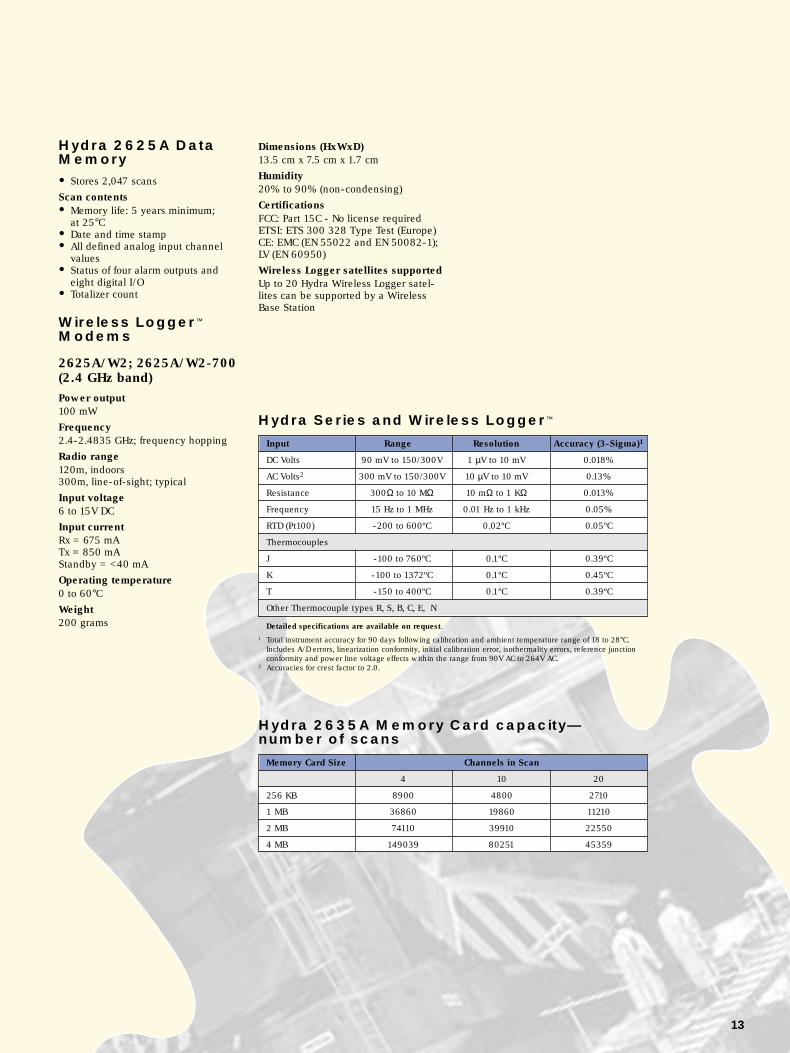
Hydra Series and Wireless Logger™
Detailed specifications are available on request.1 Total instrument accuracy for 90 days following calibration and ambient temperature range of 18 to 28°C.
Includes A/D errors, linearization conformity, initial calibration error, isothermality errors, reference junctionconformity and power line voltage effects within the range from 90V AC to 264V AC.
2 Accuracies for crest factor to 2.0.
Hydra 2635A Memory Card capacity—number of scans
Hydra 2625A DataMemory
• Stores 2,047 scans
Scan contents• Memory life: 5 years minimum;
at 25°C• Date and time stamp• All defined analog input channel
values• Status of four alarm outputs and
eight digital I/O• Totalizer count
Wireless Logger™
Modems
2625A/W2; 2625A/W2-700(2.4 GHz band)Power output100 mW
Frequency2.4-2.4835 GHz; frequency hopping
Radio range120m, indoors300m, line-of-sight; typical
Input voltage6 to 15V DC
Input currentRx = 675 mATx = 850 mAStandby = <40 mA
Operating temperature0 to 60°CWeight200 grams
Dimensions (HxWxD)13.5 cm x 7.5 cm x 1.7 cm
Humidity20% to 90% (non-condensing)
CertificationsFCC: Part 15C - No license requiredETSI: ETS 300 328 Type Test (Europe)CE: EMC (EN 55022 and EN 50082-1);LV (EN 60950)
Wireless Logger satellites supportedUp to 20 Hydra Wireless Logger satel-lites can be supported by a WirelessBase Station
Memory Card Size Channels in Scan
4 10 20
256 KB 8900 4800 2710
1 MB 36860 19860 11210
2 MB 74110 39910 22550
4 MB 149039 80251 45359
Input Range Resolution Accuracy (3-Sigma)1
DC Volts 90 mV to 150/300V 1 µV to 10 mV 0.018%
AC Volts2 300 mV to 150/300V 10 µV to 10 mV 0.13%
Resistance 300Ω to 10 MΩ 10 mΩ to 1 KΩ 0.013%
Frequency 15 Hz to 1 MHz 0.01 Hz to 1 kHz 0.05%
RTD (Pt100) -200 to 600ºC 0.02ºC 0.05ºC
Thermocouples
J -100 to 760ºC 0.1ºC 0.39ºC
K -100 to 1372ºC 0.1ºC 0.45ºC
T -150 to 400ºC 0.1ºC 0.39ºC
Other Thermocouple types R, S, B, C, E, N

14
• Universal Input Module:Connect 20 analog inputsof virtually any sensor typewithout external signalconditioning
• NetDAQ Interfacing: Portsfor both 10Base-2(coaxial)and10Base-T (twisted pair)are provided for convenientnetwork cabling. RS-232input for calibration
• External Trigger: Activatescanning with real-worldevents
• Totalizer: Count on/off events,value reported withevery scan
• Alarm Outputs: Flag out-of-limit conditions to externaldevices
• Power: Accepts 107-264V AC,or 9-16V DC. Can operatefrom both simultaneously forfail-safe power operation
NetDAQ® 2640A/2645A
Channel capacityAnalog inputs: 20Computed channels: 10
Computed channelsTen computed channels can be createdby processing analog input channelsand other computed channels withaddition, subtraction, multiplication,division, log, natural log, exponent,square root, absolute value, and integerfunctions.
In addition, the following predefinedselections are available: the average ofa group of channels, the differencebetween any two channels, the differ-ence between a channel and a group ofaveraged channels.
Measurement rate (2640A)Slow: 6 Rdgs/s nominalMedium: 41 (50 Hz), 48 (60 Hz) Rdgs/snominalFast: 100 Rdgs/s nominal(5 Rdgs/s for V AC nominal, 140 Rdgs/son 300Ω range, 37 Rdgs/s on 3 MΩrange)
Measurement rate (2645A)Slow: 45 (50 Hz), 54 (60 Hz) Rdgs/snominalMedium: 200 Rdgs/s nominalFast: 1000 Rdgs/s nominal(5 Rdgs/s for V AC nominal, 370 Rdgs/son 300Ω range, 44 Rdgs/s on 3 MΩrange)
Analog to digital converter2640A: Multi-slope type, linear to 18 bits2645A: Multi-slope type, linear to 16 bits
Common mode rejection2640A: AC: ≥120 dB (50/60 Hz, ±10.1%max 1 kΩ source imbalance);DC: ≥120 dB2645A: AC: ≥100 dB (50/60 Hz, ±10.1%max 1 kΩ source imbalance);DC: ≥100 dB
Normal mode rejection50 dB @ 50/60 Hz, ±10.1%
Common mode and normal modevoltage maximum2640A: 300V DC or V AC rms (channels1,11); 150V DC or V AC rms (all otherchannels)2645A: 50V DC or 30V AC rms (allchannels)
Isolation2640A: Analog input to analog input,and analog input to any digital input;meets IEC 1010-1 Category II ANSI/ISA-82.01-1994 and CSA-C22.2 No. 1010.1-92 for 150/300 volts reinforced2645A: Analog input to any digitalinput; meets IEC 1010 Category II,ANSI/ISA-82.01-1994 and CSA-C22.2No. 1010.1-92 for 150/300 voltsreinforced
Current measurementsAC or DC current measurements up to100 mA may be accomplished using the2620A-101 10Ω Current Shunt Strip
Totalizing inputDC coupled, non-isolated, max +30V,min -4VMax count: 4,294,967,295Minimum signal: 2V peakThreshold: 1.4VRate: 0-5 kHz (debounce off)Hysteresis: 500 mVInput debouncing: None or 1.66 ms
Digital inputsThreshold: 1.4VHysteresis: 500 mVMaximum input: +30V, min -4V;non-isolated
Digital/master alarm outputsThe open collector output lines are non-isolated, TTL compatible
Digital I/O and alarm outputs8 total; totalizer: 1
Alarm associationsDigital I/O may be used as a digitalinput or alarm status output (associatedwith any input channel or channels)
Trigger inputMinimum pulse: 5 µsMinimum latency: 2 msRepeatability: 1 msInput “High”: 2.0V min, 7.0V maxInput “Low”: -0.6V min, 0.8V maxnon-isolated, contact closure and TTLcompatible
NetDAQ® Specifications
NetDAQ rear panel.
15
ClockAccurate to within 1 minute/month for0 to 50°C range
Power107 to 264V AC, 50 or 60 Hz (<15 watts),or 9 to 16V DC (<6 watts). (If bothsources are applied simultaneously, thegreater of AC or DC is used.) At 120V ACthe equivalent DC voltage ~14.5V.
Temperature, humidity(non-condensing)Operating:-20 to 28°C, ≤90% RH28 to 40°C, ≤75% RH40 to 60°C, ≤50% RHStorage: -40 to 70°C, 5 to 95% RH
AltitudeOperating: 2000mStorage: 12,200m
Electromagnetic Interference (EMI)Passes FCC EMI Class B Equipment, Vfg.243, European Norms EN50081-1 andEN50082-1, CE approved
SafetyComplies with applicable sections of CE,IEC 1010-1, ANSI/ISA-S82.01-1994,CSA-C22.2 No. 1010.1-92 and CSAstandards as noted under “Isolation”
Weight3.7 kg
Dimensions (HxWxD)9.3 cm x 21.6 cm x 39.4 cm
Battery life10 years minimum for real-time clock
InterfacesEthernet: Conforms to IEEE 802.3Ethernet standard. Compatible with10Base-2 and 10Base-T standards. UsesTCP/IP protocol.RS-232C: For calibration only. Theoptional NetDAQ Service Manual providesstep-by-step calibration instructions.
Data buffer memoryEach scan consists of computed chan-nels, time stamp, all defined analoginput channels, the status of the eightdigital I/O, and the totalizer count.
The number of stored scans varieswith the number of channels configuredranging from 6400 scans for 1 config-ured channel to 1,896 scans for 20configured channels.
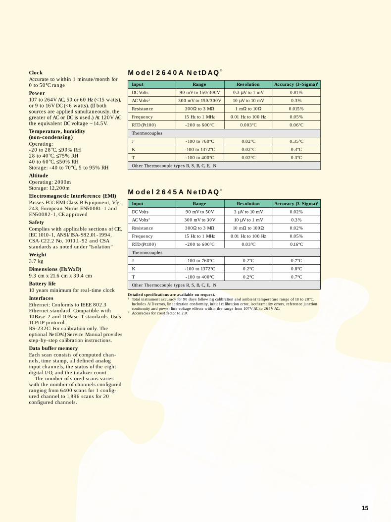
Model 2645A NetDAQ®
Detailed specifications are available on request.1 Total instrument accuracy for 90 days following calibration and ambient temperature range of 18 to 28°C.
Includes A/D errors, linearization conformity, initial calibration error, isothermality errors, reference junctionconformity and power line voltage effects within the range from 107V AC to 264V AC.
2 Accuracies for crest factor to 2.0.
Model 2640A NetDAQ®
Input Range Resolution Accuracy (3-Sigma)1
DC Volts 90 mV to 150/300V 0.3 µV to 1 mV 0.01%
AC Volts2 300 mV to 150/300V 10 µV to 10 mV 0.3%
Resistance 300Ω to 3 MΩ 1 mΩ to 10Ω 0.015%
Frequency 15 Hz to 1 MHz 0.01 Hz to 100 Hz 0.05%
RTD (Pt100) -200 to 600ºC 0.003ºC 0.06ºC
Thermocouples
J -100 to 760ºC 0.02ºC 0.35ºC
K -100 to 1372ºC 0.02ºC 0.4ºC
T -100 to 400ºC 0.02ºC 0.3ºC
Other Thermocouple types R, S, B, C, E, N
Input Range Resolution Accuracy (3-Sigma)1
DC Volts 90 mV to 50V 3 µV to 10 mV 0.02%
AC Volts2 300 mV to 30V 10 µV to 1 mV 0.3%
Resistance 300Ω to 3 MΩ 10 mΩ to 100Ω 0.02%
Frequency 15 Hz to 1 MHz 0.01 Hz to 100 Hz 0.05%
RTD (Pt100) -200 to 600ºC 0.03ºC 0.16ºC
Thermocouples
J -100 to 760ºC 0.2ºC 0.7ºC
K -100 to 1372ºC 0.2ºC 0.8ºC
T -100 to 400ºC 0.2ºC 0.7ºC
Other Thermocouple types R, S, B, C, E, N
CERT IFIED TO MEET ISO
9001
QUALIT
Y MANAGEMENT SYSTEM
ISO 9001
Customer support
Choosing a data acquisition sys-tem that meets your specificationsis just the first step in making asmart equipment investment. Youalso need to choose a companythat can help you get up andrunning quickly and easily andthat will support you throughoutthe life of the system.
Fluke has addressed theseissues by assembling a widevariety of searvices that are solidlybacked by our sales and applica-tion support teams, world-wideservice centers, and state-of-the-art parts supply system. Our offer-ings range from comprehensiveservice programs and technicaltraining to custom programmingand system consulting.
Fluke CorporationPO Box 9090Everett, WA USA 98206-9090
Fluke Europe B.V.PO Box 1186, 5602 BD Eindhoven,The Netherlands
For more information call:U.S.A. (800) 443-5853 or Fax (425) 356-5116Europe/M-East +31 (0) 40 2678 200 or Fax +31 (0) 40 2678 222Canada (905) 890-7600 or Fax (905) 890-6866Other countries +1 (425) 356-5500 or Fax (425) 356-5116
Web access: http://www.fluke.comEmail: [email protected]
©1997 Fluke Corporation. Specifications subject to change without notice.NetDAQ is a trademark of Fluke Corporation. Microsoft, MS-DOS, Windows,and Windows NT are registered trademarks of Microsoft Corporation. Novellis a registered trademark of Novell, Inc. All rights reserved.Printed in the Netherlands11/97 G0394EEN Rev A
Fluke measurementspecificationphilosophy
The accuracy specifications forHydra and NetDAQ instrumentsare calculated conservatively sothat they include three standarddeviations from the nominalvalue—this is referred to as3-Sigma. Greater than 99.7% ofthe instruments produced willperform within the error limits.Rigorous screening and testingprocedures catch and correct thethree out of 1000 instrumentswhich could have fallen outsidetheir published specifications.Many other products use a ‘root-sum-square’ scheme, or onlyspecify the error band within onestandard deviation (1-Sigma) ofnominal. This method produces aspecification that appears to bemore accurate, but the resulting“typical” specifications correctlycharacterize only ~66% of theinstruments produced. Thismethod is kind of like knowinghow accurate “most of the instru-ments” will be. NetDAQ’s3-Sigma specifications tell youhow accurate ALL of the instru-ments will be.Note: Listed specifications are summary innature. Accuracies listed are most favorablewithin the stated range. You may obtaindetailed specifications by contacting theoffices listed on this page.
For complete product specifica-tions or information on other Flukeproducts, contact your local Flukesales representative.
Extended warrantyservice agreementsWarranty extensions are available,in some locations to cover neces-sary repairs and performancetesting, including parts, labor,and return-surface freight costs.Warranty extensions may not beavailable in all countries. Contactyour local Fluke sales office forspecific details.
Service parts andspare parts kitsA complete inventory of Flukereplacement parts, subassemblies,and modules are available.
Contact your local sales officeto find out more about the serviceprograms available in your area orto develop a customer programthat suits your needs and budget.
Fluke. Keeping your worldup and running.