data acquisition - department of mechanical · pdf filebalkan-data acquisition 40 the input...
TRANSCRIPT

DATA ACQUISITIONDATA ACQUISITION
Prof. Dr. Tuna Balkan
Fall 2003-2004

Balkan-Data Acquisition 2
What is Data Acquisition?What is Data Acquisition?
Data acquisition systems are used by most engineers and scientists for laboratory research, industrial control, test and measurement to input and output data to and from a computer.

Balkan-Data Acquisition 3
A data acquisition and control system typically consist of the followings:
Sensors which measure physical variables such as temperature, strain, pressure, flow, force and motion (displacement, velocity, and acceleration)

Balkan-Data Acquisition 4
Signal conditioning, to convert the sensor outputs into signals readable by the analog input board(A/D) in the PC.
An analog input (A/D) board, to convert these signals into digital format usable by the PC.

Balkan-Data Acquisition 5
A computer with the appropriate application software to process, analyze and log the data to disk. Such software may also provide a graphical display of the data.
An output interface, to provide an appropriate process control response.
Balkan-Data Acquisition 6
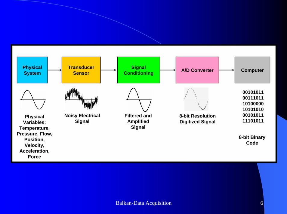
Physical System
Transducer Sensor
Signal Conditioning A/D Converter Computer
Physical Variables:
Temperature, Pressure, Flow,
Position, Velocity,
Acceleration, Force
Noisy Electrical Signal
Filtered and Amplified
Signal
8-bit Binary Code
001010110011101110100000101010100010101111101011
8-bit Resolution Digitized Signal

Balkan-Data Acquisition 7
In order to sense and measure physical variables such as pressure, flow and motion, it is necessary to use transducers (sensors), which convert physical variables into electrical signals and transmit these signals either to a signal conditioning device or directly to the data acquisition board.

Balkan-Data Acquisition 8
The signal conditioning device performs the following main functions:Supplies power to the transducer, when required,Amplifies, filters or digitizes the sensor signal,Provides appropriate output signal which is easy to capture with an analog input board.

Balkan-Data Acquisition 9
Signal conditioners frequently perform additional functions such asbridge balancing,integration,output calibration,overload detection,signal level monitoring.
Balkan-Data Acquisition 10
Signal conditioners must perform these functions over the amplitude and frequency range of the expected input signal.
Signal conditioners have a large effect on measurement system performance characteristics.

Balkan-Data Acquisition 11
After signal conditioning, the sensor signal is passed to the analog input (A/D) board.
The A/D board converts the conditioned analog voltage or current signal into a digital format which is readable by the PC.

Balkan-Data Acquisition 12
An analog signal is continuous-time function with a physical parameter defined for every instance of time. The signal must be converted into a discrete-time signal so that it can be used by the computer to depict the original signal.

Balkan-Data Acquisition 13
A/D conversion is a ratio operation, where the input signal is compared to a reference and converted into a fraction which is then represented as a coded digital number.To optimize measurement accuracy, there is a minimum and maximum number of data points that need to be acquired.

Balkan-Data Acquisition 14
A/D boards often incorporate some of the capabilities below:High-speed data transfer to the PCNoise and anti-aliasing filteringProgrammable gain amplifierCircuitry for hardware and software triggering

Balkan-Data Acquisition 15
Sampling RateSampling Rate
One of the most critical factors when selecting an A/D board is sampling rate (speed).The sampling rate is a measure of how rapidly the A/D board can scan the input channel and identify the discrete value of the signal present with respect to a reference signal.

Balkan-Data Acquisition 16
4 Samplesper Cycle
8 Samplesper Cycle
Analog Waveform
16 Samplesper Cycle

Balkan-Data Acquisition 17
If the sampling rate is too slow, then a completely different waveform of a lower frequency is constructed from the data acquired. This effect is called aliasing.

Balkan-Data Acquisition 18
AliasingAliasing
It has the effect of increasing the variance in the recorded signal, i.e. it adds noise to the signal, basically by missing the peaks and troughs of the rapidly changing signal.

Balkan-Data Acquisition 19
So, even if the signal has the same peak all the time, the board will catch the rising and falling phase but miss the peak giving the appearance that the peak (i.e. the maximum value recorded in each cycle) is changing.

Balkan-Data Acquisition 20
If you aren’t measuring a regularly repeating signal then you won’t see such a dramatic aliasing phenomenon.
Instead you’ll just see that if you measure more than once the response will vary in size a lot.

Balkan-Data Acquisition 21
To avoid aliasing, it is necessary that the sample rate be at least twice the highest expected frequency input.

Balkan-Data Acquisition 22
Sample every 20 msSample every 1 ms
Sampling at a rate that is slow relative to the rate of change of the signal (red) results in undersampling. You must attempt to match sampling rate to the signal you are interested in.

Balkan-Data Acquisition 23
Sine wave of 160 Hz (6.25 ms between peaks)
2 ms
The wiggling of the trace up and down is the ALIASING.

Balkan-Data Acquisition 24
1 ms

Balkan-Data Acquisition 25
0.1 ms

Balkan-Data Acquisition 26
Oversampling will provide a true picture of the time course of the event being studied but too much oversampling will result in very large data files.E.g. at 10 kHz sampling rate, one second of 12 bit data is 20 Kbytes.If you have 2 data channels then that is 40 KB/s or 2.4 MB/min.

Balkan-Data Acquisition 27
ResolutionResolution
Resolution defines the number of divisions into which a full-scale input range can be divided to approximate an analog input.

Balkan-Data Acquisition 28
ExampleExample
Recording the ambient temperature during the day manually at intervals of 30 minutes.

Balkan-Data Acquisition 29
Time Temperature(°C)06:00 1006:30 1107:00 1107:30 1208:00 1308:30 1309:00 1409:30 1410:00 15
Time Temperature (°C)10:30 1511:00 1512:00 1712:30 1813:00 1913:30 1914:00 1914:30 1815:00 1615:30 15

Balkan-Data Acquisition 30
Rather than having to make the measurements manually and then transfer them to the computer by the keyboard it is easier to use a transducer and data acquisition board in the computer to directly record the temperature every 30 minutes.

Balkan-Data Acquisition 31
A platinum resistance thermometercan be used as the transducer which is a temperature-dependent resistor, and by using an appropriate circuit, a continuous measurement of actual the temperature in the form of a proportional voltage can be obtained.

Balkan-Data Acquisition 32
The data acquisition software converts the analog voltage corresponding to the temperature into binary numbers (digital format) in every 30 minutes. Since A/D board has finite resolution, a small range of analog values will all produce the same binary number after conversion.
Balkan-Data Acquisition 33
Assume that the A/D board rounds off all numbers within its operating range to the nearest 1°C. That is although the ambient temperature changes continuously, the A/D board only indicates a change in it when a difference greater than 1°C is observed. The data thus changes in 1°C steps.

Balkan-Data Acquisition 34

Balkan-Data Acquisition 35
In a real A/D board the total measurement range is divided into a fixed number of possible values. The number of values is a power of two, often referred to as the number of bits. Commonly used values are:
8 bits = 28 256 values12 bits = 212 4,096 values16 bits = 216 65,536 values

Balkan-Data Acquisition 36
If it is desired to measure a 0-10V (or ±5V) signal, and the A/D board has 8-bit resolution, the input signal can be measured in steps of 10/28=10/256=0.039V=39 mV.
A 10V analog input is equal to the digital number 255, and a 0V analog input equals 0.

Balkan-Data Acquisition 37
This A/D board is capable of detecting only input changes greater than 0.039V.
Each 0.039V change in the input is indicated by adding or subtracting 1 from the previous number i.e. 9.961V is digitally represented by 254.

Balkan-Data Acquisition 38
An 12 bit board would be more sensitive to changes in the input voltage since its minimum resolution would be
10V/4096 = 2.44mV

Balkan-Data Acquisition 39
2 Bitconversion
3 Bitconversion
Analog Waveform
5 Bitconversion
Balkan-Data Acquisition 40
The input signal should not exceed 10V or the data acquisition board will saturateand it will not be able to report changes in the voltage as a function of time.This effect will be seen as a perfectly flat line on the computer screen at 255 = 10V

Balkan-Data Acquisition 41
Even with a 12 bit A/D, it is necessary to use amplifiers prior to the input to the board in order to boost the signal so as to make use of a reasonable portion of the A/D range.

Balkan-Data Acquisition 42
For example, the output of a thermometer might only change 1mV/°C, which would mean that the temperature would have to change by 2.5°C before the 12-bit board would indicate a change in digitized value.

Balkan-Data Acquisition 43
By amplifying the signal output of the thermometer by x1000, each bit on the board is equivalent to a change in output of the thermometer of 0.001 mV which is equal to 0.0025 °C.Amplifiers are generally used to adjust the magnitude of the output of the transducers to match the input range of the A/D board.

Balkan-Data Acquisition 44
Sometimes it is also necessary to adjust the baseline voltage after amplifying.If temperature changes around room temperature are measured with x1000 amplification, then room temperature of 22°C is measured as 22V, which is much greater than the input range of the board. Therefore, it is necessary to adjust the output of the amplifier with an offset.

Balkan-Data Acquisition 45
A preset offset may be applied.The output of the amplifier is adjusted so that 22V would be offset by -22V, and the output at room temperature would be 0V.Thus, the fluctuations of ±5°C around 22°C could be recorded by the computer without saturating the board.

Balkan-Data Acquisition 46
Input ConfigurationInput ConfigurationThere are two basic options when connecting the input signals:- Single-ended (SE)- Differential (Diff)SE inputs offer the lower cost per input. However, differential inputs offer greater noise immunity for more accurate readings. A typical A/D board offers 16 SE or 8 differential input channels.

Balkan-Data Acquisition 47
Input
Floating Signal Source(Not Connected to Building Ground)Examples• Ungrounded Thermocouples• Signal conditioning with isolated
outputs• Battery devices
Grounded Signal SourceExamples• Plug-in instruments with nonisolated outputs
Differential
(DIFF)
Signal Source Type

Balkan-Data Acquisition 48
Input
Floating Signal Source(Not Connected to Building Ground)Examples• Ungrounded Thermocouples• Signal conditioning with
isolated outputs• Battery devices
Grounded Signal SourceExamples• Plug-in instruments with nonisolated outputs
Single-EndedGround Referenced
(RSE)
Signal Source Type

Balkan-Data Acquisition 49
Input
Floating Signal Source(Not Connected to Building Ground)Examples• Ungrounded Thermocouples• Signal conditioning with
isolated outputs• Battery devices
Grounded Signal SourceExamples• Plug-in instruments with nonisolated outputs
Single-EndedNon Referenced
(NRSE)
Signal Source Type

Balkan-Data Acquisition 50
SingleSingle--Ended vs. Differential InputsEnded vs. Differential Inputs
SE inputs should be utilized whenever analog measurements are to be made with respect to a common external ground and there is no practical way to bring both a remote ground and the analog ground back to the Data Acquisition System’s front end.

Balkan-Data Acquisition 51
Differential input configuration should be used when:
Measuring signals with large common mode voltages, like many strain gauges.The input sensor is physically distant from the Data Acquisition System.

Balkan-Data Acquisition 52
Several sensors with no common ground are to be measured. Connecting the LOW side of each sensor together at a common point can create unwanted ground currents, resulting in offset and noise errors.

Balkan-Data Acquisition 53
The Common Mode Rejection of a true differential input offers noise immunity from cable or transmission line pickup.

Balkan-Data Acquisition 54
Analog Outputs (D/A)Analog Outputs (D/A)Analog outputs are generated using a procedure which is exact reciprocal of that used to read analog inputs.
The user writes a binary word, which represents a percentage of the full-scale range, to the output register.

Balkan-Data Acquisition 55
The D/A converter generates the analog level until the register is updated.
The output rate is a function of the settling time and is critical in determining the maximum frequency of the output waveform.

Balkan-Data Acquisition 56
An analog output is typically required for any application involving a variable control device such as a servo motor or servo valve.The outputs may be configured as voltages (0-10V, 0-5V, ±10V, ±5V) or as a 4-20mA current sources.

Balkan-Data Acquisition 57
Digital Inputs and Outputs Digital Inputs and Outputs (DIO)(DIO)
Most analog input/output boards also incorporate general-purpose digital input/output channels which are useful for many system functions.
Balkan-Data Acquisition 58
Digital I/O lines are commonly used when:To sense and control high-power AC/DC voltages through solid-state relays.For low-current TTL signals like limit-switch inputs and other digital lines.

Balkan-Data Acquisition 59
Digital I/O lines can also be used for parallel communication between plug-in expansion cards and to generate strobe, pulse, clock, and other timing signals.
Special-purpose digital I/O boards which use interrupt-driven control can operate in the background while the computer is running another application.

Balkan-Data Acquisition 60
Data Acquisition by Using Data Acquisition by Using Simulink/MATLABSimulink/MATLAB®®
Easy to useToolboxes for different applicationsReal-time simulationControl ApplicationsSoftware drivers for common boards

Balkan-Data Acquisition 61
Mahtworks Web Site :Mahtworks Web Site :www.mathworks.com
Alternative Software:LabVIEW LabVIEW ®by National InstrumentsWeb Site:Web Site:www.ni.com

Balkan-Data Acquisition 62
Simulink®®
Run MATLAB® (Latest version 6.5 Rev13)Welcome screen of Matlab®
Select SimulinkSimulink Library Browser

Balkan-Data Acquisition 63
Don’t forget to setup Real-Time Windows Target.
On the Command Window typertwintgt -setupYou are going to install the Real-Time Windows Target kernel.Do you want to proceed? [y] : yThe Real-Time Windows Target kernel has been successfully installed.

Balkan-Data Acquisition 64
You should have a data acquisition card installed in the computer.
In the following example, a NI PCI6025E card is used.

Balkan-Data Acquisition 65
You should have one of the following C-compilers installed in your computer.
Watcom C/C++ (Version 10.6 or higher)
Microsoft Visual C/C++ (Version 5.0 or higher)

Balkan-Data Acquisition 66
SelectNEWorOPEN(a previous model file)
Balkan-Data Acquisition 67
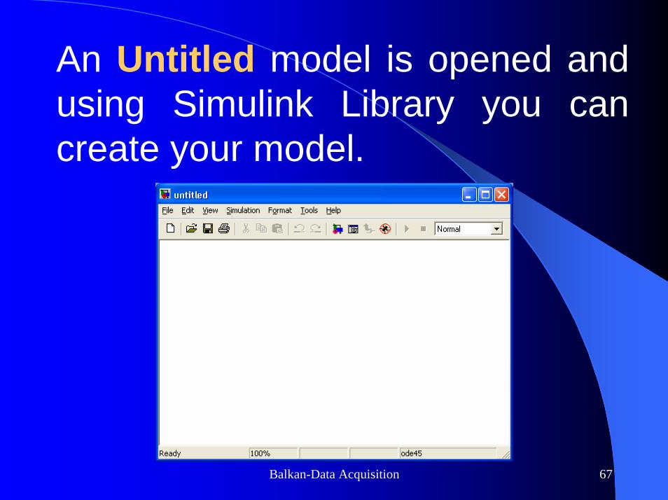
An Untitled model is opened and using Simulink Library you can create your model.

Balkan-Data Acquisition 68
SIMPLE EXAMPLESSIMPLE EXAMPLES

Balkan-Data Acquisition 69
Simple PIDSimple PID--control System control System using a Data Acquisition using a Data Acquisition Card with Analog OutputCard with Analog Output
Problem: Find the unit step response of the system and display it on the scope with the input.

Balkan-Data Acquisition 70
Click onReal-TimeWindowsTarget
x-PC Target is now more popular.

Balkan-Data Acquisition 71
Drag Analog Inputand Analog Outputiconsto model

Balkan-Data Acquisition 72
Double Click on Analog Inputand Analog Outputiconsfor setting
Balkan-Data Acquisition 73
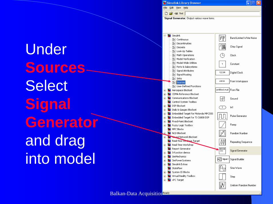
UnderSourcesSelectSignalGeneratorand drag into model

Balkan-Data Acquisition 74
UnderSinksSelectScopeand drag into model

Balkan-Data Acquisition 75
UnderSignals and SystemsSelectMuxand drag into model

Balkan-Data Acquisition 76
SelectPID ControllerUnderSimulinkExtras
AdditionalLinear
and drag intomodel

Balkan-Data Acquisition 77
UnderDiscontinuitiesSelectSaturationand drag intomodel

Balkan-Data Acquisition 78
UnderMath OperationsSelectSumand drag intomodel

Balkan-Data Acquisition 79
Complete ModelComplete Model

Balkan-Data Acquisition 80
Select Select Simulation ParametersSimulation Parametersunder under SimulationSimulation MenuMenu

Balkan-Data Acquisition 81
Set Set Solver Solver ParametersParameters

Balkan-Data Acquisition 82
Set mode to Set mode to ExternalExternal

Balkan-Data Acquisition 83
BuildBuild and and Run Run the model the model

Balkan-Data Acquisition 84
Open Open Scope Scope by double clicking on it by double clicking on it

Balkan-Data Acquisition 85
Set Set Scope ParametersScope Parameters

Balkan-Data Acquisition 86
Set Set FormatFormat to Array, remove the tick to Array, remove the tick on on Limit data pointsLimit data points to last, tick to last, tick Save Save
data to workspacedata to workspace, and give a , and give a variable namevariable name..
Balkan-Data Acquisition 87
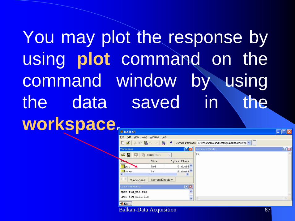
You may plot the response by using plot command on the command window by using the data saved in the workspace.

Balkan-Data Acquisition 88
Examples from System ResponsesExamples from System Responses(P(P--control)control)

Balkan-Data Acquisition 89
Examples from System ResponsesExamples from System Responses(PD(PD--control)control)

Balkan-Data Acquisition 90
Examples from System ResponsesExamples from System Responses(PD(PD--control)control)

Balkan-Data Acquisition 91
Examples from System ResponsesExamples from System Responses(PID(PID--control)control)

Balkan-Data Acquisition 92
Examples from System ResponsesExamples from System Responses(PID(PID--control)control)

Balkan-Data Acquisition 93
Data Acquisition using Data Data Acquisition using Data Acquisition Toolbox and your Acquisition Toolbox and your
sound card’s microphone sound card’s microphone input and speaker outputsinput and speaker outputs
Balkan-Data Acquisition 94
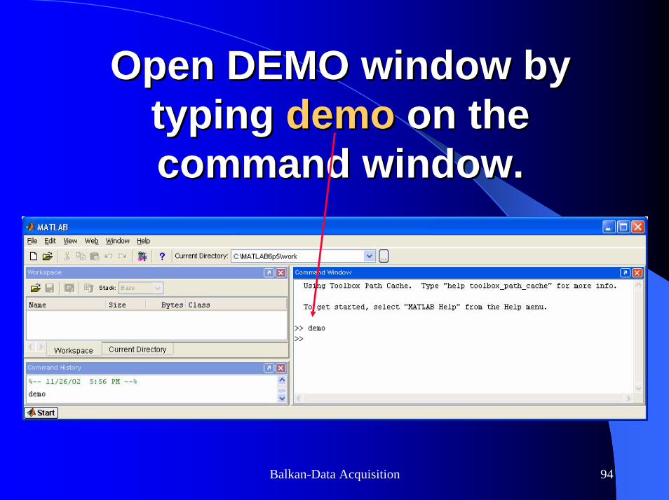
Open DEMO window by Open DEMO window by typing typing demodemo on the on the command window.command window.

Balkan-Data Acquisition 95
SelectSelect Data AcquisitionData AcquisitionExample Function GeneratorExample Function Generator..

Balkan-Data Acquisition 96
Start demo for Start demo for analog outputanalog output. . You will hear sound with You will hear sound with
frequency 500 Hz.frequency 500 Hz.

Balkan-Data Acquisition 97
SelectSelect Data AcquisitionData AcquisitionExample Function GeneratorExample Function Generator..

Balkan-Data Acquisition 98
Start demo for Start demo for analog inputanalog inputfrom microphone. You will see from microphone. You will see
sound waves on the scope.sound waves on the scope.

Balkan-Data Acquisition 99
Look at the other demos for Look at the other demos for different applications.different applications.

Balkan-Data Acquisition 100
DATA ACQUISITIONDATA ACQUISITIONNext LectureNext Lecture
Real Time Position Real Time Position Control of a Motor and Control of a Motor and
Load (in class)Load (in class)