data book - · pdf filefesx 512s-35c data book uni systems do brasil ltda serial no: ... this...
TRANSCRIPT
FESX 512S-35C
DATA BOOK
Uni Systems do Brasil LtdaSerial No: 4158520Drawing: 7952006PI: 270.923
A L F A L A V A L S E P A R A T I O N
A L F A L A V A L S E P A R A T I O N
CH/FESX 512S-35CG
Separator Manual
Product No. 881119-01-03
Book No. 1271013-02 V2
Alfa Laval LtdaSão Paulo - Brazil
Telephone: +55 11 5188 6000Telefax: +55 11 5188 6005
Printed in Sweden, 97-07
© Alfa Laval Separation AB 1997
This publication or any part thereof may not be reproduced or transmitted by any process or means without prior written permission of Alfa Laval Separation AB.
Contents
1 Read this first 7
2 Safety Instructions 9
3 Separator Basics 15
3.1 Basic principles 17
3.2 Design and function 20
3.3 Definitions 26
4 Operating Instructions 27
4.1 Operating routine 29
4.2 Before first start 29
4.3 Ready for start 30
4.4 Start 31
4.5 Running 32
4.6 Normal stop 33
4.7 Emergency stop 34
5 Periodic maintenance 35
5.1 Introduction 37
5.2 Maintenance Logs 41
5.3 Check points at Intermediate Service (IS) 47
5.4 Check points at Major Service (MS) 60
5.5 Lifting instructions 66
5.6 Cleaning 68
5.7 When changing oil 71
5.8 Vibration 75
5.9 Common maintenance directions 76
3

6 Dismantling/Assembly 81
6.1 Introduction 83
6.2 Machine top part with inlet device 85
6.3 Separator bowl 90
6.4 Nozzles 100
6.5 Machine bottom part 102
6.6 Vertical driving device 106
6.7 Horizontal driving device 122
6.8 Motor 136
6.9 Frame feet 143
6.10 Monitoring kit 145
6.11 Microphone arm, kit (option) 146
7 Trouble-Tracing 147
7.1 Mechanical faults 149
7.2 Clarification faults 151
8 Technical Reference 153
8.1 Technical data 155
8.2 Basic size drawing 156
8.3 Connection list 158
8.4 Interface description 160
8.5 Outlet nozzles 166
8.6 Revolution counter 167
8.7 Compressed air 168
8.8 Water quality 169
8.9 Lubricants 171
8.10 Other drawings 178
8.11 Machine plates and safety labels 186
8.12 Interconnection diagram 189
8.13 Storage and installation 190
4
ls and observe the ion, operation, .
ions can result in
clear only foreseeable conditions ings are given, therefore, for
ended usage of the machine and its
Study instruction manuawarnings before installatservice and maintenance
Not following the instructserious accidents.
In order to make the informationhave been considered. No warnsituations arising from the uninttools.
5

6

1 Read this first
This manual is designed for operators and service engineers working with the Alfa Laval separator CH/FESX 512S-35CG.
For information concerning the function of the separator, see chapter ‘‘3 Separator Basics” on page 15, and chapter ‘‘8 Technical Reference” on page 153.
If the separator has been delivered and installed by Alfa Laval as part of a processing system, this manual is a part of the system documentation. In this case, study carefully all the instructions in the system documentation.
In addition to this separator manual a Spare Parts Catalogue, SPC is supplied.
This separator manual consists of:
Safety Instructions
Pay special attention to the safety instructions for the separator. Not following the safety instructions can cause accidents resulting in damage to equipment and serious injury to personnel.
Separator Basics
Read this chapter if you are not familiar with this type of separator. This chapter contains the technical description and function description.
Operating Instructions
This chapter contains operating instructions for the separator only.
S0
0680
11
Separator Manual and Spare Parts Catalogue
7
1 Read this first
Service Instructions
This chapter gives instructions for daily checks, cleaning, oil changes, servicing and check points.
Dismantling / Assembly
This chapter contains step-by-step instructions for dismantling and assembly of the separator for service and repair.
Trouble-tracing
Refer to this chapter if the separator functions abnormally.
If the separator has been installed as part of a processing system always refer to the trouble-tracing part of the system documentation first.
Technical Reference
This chapter contains technical data and drawings concerning the separator.
8
2 Safety Instructions
G00
1041
1
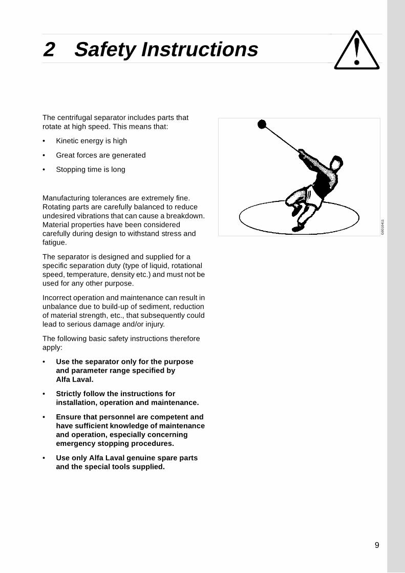
The centrifugal separator includes parts that rotate at high speed. This means that:
• Kinetic energy is high
• Great forces are generated
• Stopping time is long
Manufacturing tolerances are extremely fine. Rotating parts are carefully balanced to reduce undesired vibrations that can cause a breakdown. Material properties have been considered carefully during design to withstand stress and fatigue.
The separator is designed and supplied for a specific separation duty (type of liquid, rotational speed, temperature, density etc.) and must not be used for any other purpose.
Incorrect operation and maintenance can result in unbalance due to build-up of sediment, reduction of material strength, etc., that subsequently could lead to serious damage and/or injury.
The following basic safety instructions therefore apply:
• Use the separator only for the purpose and parameter range specified by Alfa Laval.
• Strictly follow the instructions for installation, operation and maintenance.
• Ensure that personnel are competent and have sufficient knowledge of maintenance and operation, especially concerning emergency stopping procedures.
• Use only Alfa Laval genuine spare parts and the special tools supplied.
9

2 Safety Instructions
kPam /h3
3o
C
rpmHz
kg/m
S00
513
11S
005
5611
DANGER
Disintegration hazards
• Use the separator only for the purpose and parameter range specified by Alfa Laval.
• If excessive vibration occurs, stop separator and keep bowl filled with liquid during rundown.
• When power cables are connected, always check direction of motor rotation. If incorrect, vital rotating parts could unscrew.
• Check that the gear ratio is correct for power frequency used. If incorrect, subsequent overspeed may result in a serious break down.
• Welding or heating of parts that rotate can seriously affect material strength.
• Wear on the large lock ring thread must not exceed safety limit. φ-mark on lock ring must not pass opposite φ-mark by more than specified distance.
• Inspect regularly for corrosion and erosion damage. Inspect frequently if process liquid is corrosive or erosive.
10

2 Safety Instructions
S0
0511
11S
005
1011
S0
0517
11S
005
1611
DANGER
Entrapment hazards
• Make sure that rotating parts have come to a complete standstill before starting any dismantling work.
• To avoid accidental start, switch off and lock power supply before starting any dismantling work.
• Assemble the machine completely before start. All covers and guards must be in place.
Electrical hazards
• Follow local regulations for electrical installation and earthing (grounding).
WARNING
Crush hazards
• Use correct lifting tools and follow lifting instructions.
• Do not work under a hanging load.
Noise hazards
• Use ear protection in noisy environments.
11
2 Safety Instructions
S00
554
11S
005
431
1
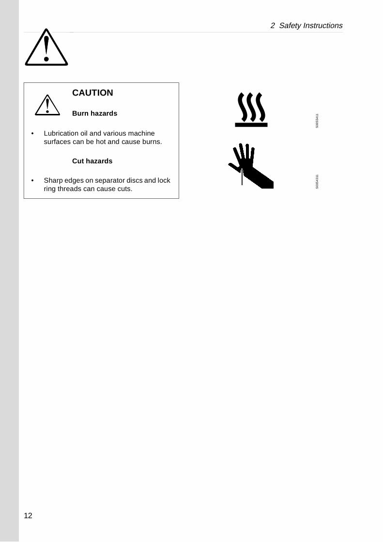
CAUTION
Burn hazards
• Lubrication oil and various machine surfaces can be hot and cause burns.
Cut hazards
• Sharp edges on separator discs and lock ring threads can cause cuts.
12
2 Safety Instructions
Warning signs in the text
Pay attention to the safety instructions in this manual. Below are definitions of the three grades of warning signs used in the text where there is a risk for injury to personnel.
DANGER
Type of hazard
This type of safety instruction indicates a situation which, if not avoided, could result in fatal injury or fatal damage to health.
WARNING
Type of hazard
This type of safety instruction indicates a situation which, if not avoided, could result in disabling injury or disabling damage to health.
CAUTION
Type of hazard
This type of safety instruction indicates a situation which, if not avoided, could result in light injury or light damage to health.
NOTE
This type of instruction indicates a situation which, if not avoided, could result in damage to the equipment.
13
2 Safety Instructions
14

3 Separator Basics
Contents
3.1 Basic principles 17
3.1.1 Separation by gravity 17
3.1.2 Centrifugal separation 17
3.1.3 Separating temperatures 18
3.1.4 Phase proportions 19
3.1.5 Size and shape of particles 19
3.1.6 The throughput 19
3.1.7 Disc stack 19
3.2 Design and function 20
3.2.1 Overview 20
3.2.2 Mechanical power transmission 21
3.2.3 Sensors and indicators 23
3.2.4 Process main parts 24
3.2.5 Separating function 25
3.3 Definitions 26
15

16

3 Separator Basics 3.1 Basic principles
G0
010
711
Sedimentation by gravity
G00
1081
1
Sedimentation in a settling tank, with outlets making it possible to separate the lighter liquid parts from the heavier
G00
1091
1
The centrifugal solution
3.1 Basic principlesThe purpose of separation can be:
• to free a liquid of solid particles,
• to separate two mutually insoluble liquids with different densities while removing any solids presents at the same time,
• to separate and concentrate solid particles from a liquid.
3.1.1 Separation by gravity
A liquid mixture in a stationary bowl will clear slowly as the heavy particles in the liquid mixture sink to the bottom under the influence of gravity.
A lighter liquid rises while a heavier liquid and solids sink.
Continuous separation and sedimentation can be achieved in a settling tank having outlets arranged according to the difference in density of the liquids.
Heavier particles in the liquid mixture will settle and form a sediment layer on the tank bottom.
3.1.2 Centrifugal separation
In a rapidly rotating bowl, the force of gravity is replaced by centrifugal force, which can be thousands of times greater.
Separation and sedimentation is continuous and happens very quickly.
The centrifugal force in the separator bowl can achieve in a few seconds what takes many hours in a tank under influence of gravity.
17
3.1 Basic principles 3 Separator Basics
G0
0110
11
High viscosity (with low temperature)
G0
0111
11
Low viscosity (with high temperature)
G00
112
11
High density (with low temperature)
G00
113
11
Low density (with high temperature)
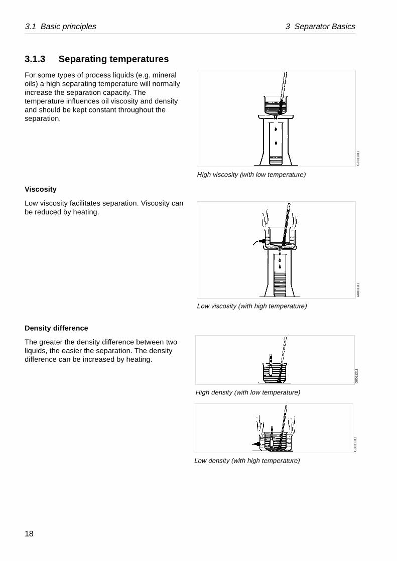
3.1.3 Separating temperatures
For some types of process liquids (e.g. mineral oils) a high separating temperature will normally increase the separation capacity. The temperature influences oil viscosity and density and should be kept constant throughout the separation.
Viscosity
Low viscosity facilitates separation. Viscosity can be reduced by heating.
Density difference
The greater the density difference between two liquids, the easier the separation. The density difference can be increased by heating.
18

3 Separator Basics 3.1 Basic principles
2 1
A
B
m³/h
µm
G0
613
311
Influence of size and shape
3.1.4 Phase proportions
An increased quantity of heavy phase in a process liquid will influence the separating result through the optimum transporting capacity of the disc stack. An increased heavy phase content can be compensated for by reducing the throughput in order to restore the optimum separating efficiency.
3.1.5 Size and shape of particles
The round and smooth particle (A) is more easily separated out than the irregular one (B).
Rough treatment, for instance in pumps, may cause a splitting of the particles resulting in slower separation. Larger particles (1) are more easily separated than smaller ones (2) even if they have the same density.
3.1.6 The throughput
The throughput sets the time allowed for the separation. A better separation result can often be achieved by reducing the throughput, i.e. by increasing the settling time.
3.1.7 Disc stack
A neglected disc stack containing deformed discs or discs coated with deposits will impair the separating result.
19

3.2 Design and function 3 Separator Basics
G0
7911
51
1. Inlet device2. Outlet, clean liquid3. Bowl4. Outlet device, sediment5. Vertical driving device with bowl spindle6. Horizontal driving device7. Frame feet8. Worm gear9. Rigid coupling10. Foundation11. Electric motor
3.2 Design and function
3.2.1 Overview
The separator comprises a processing part and a driving part. It is driven by an electric motor (11).
Mechanically, the separator machine frame is composed of a bottom part, a top part and a frame hood. The motor and separator are mounted on a common foundation (10) as shown in the illustration. The frame feet (7) are vibration damping.
The bottom part of the separator contains the horizontal driving device (6), driving shaft with a rigid coupling (9), a worm gear(8) and a vertical spindle (5).
The bottom part also contains an oil bath for the worm gear, a brake and a revolution counter.
The frame top part and the frame hood contain the processing parts of the separator, the inlet (1), outlets (2 and 4) and piping.
The liquid is cleaned in the separator bowl (3). This is fitted on the upper part of the vertical spindle and rotates at high speed in the space formed by the frame top part and frame hood. The bowl also contains nozzles which empties the sludge from the bowl.
The main inlets and outlets are shown with connection numbers in the illustration on page 24. These numbers correspond with the numbers used in the connection list and the basic size drawing which can be found in chapter ‘‘8 Technical Reference” on page 153.
20

3 Separator Basics 3.2 Design and function
G02
464
31
1. Bowl spindle2. Top bearing and spring casing3. Worm wheel4. Worm5. Rigid coupling6. Worm wheel shaft
G0
6651
61
A. ThermistorsB. Run-up period: Y-connectedC. Operation: D-connected
3.2.2 Mechanical power transmission
The main parts of the power transmission between motor and bowl are illustrated in the figure.
The transmission is fitted with a rigid coupling between the motor and worm wheel shaft. The motor is a special “control-torque motor”.
The worm gear has a ratio which increases the bowl speed several times compared with the motor speed. For correct ratio see chapter ‘‘8.1 Technical data” on page 155.
To reduce bearing wear and the transmission of bowl vibrations to the frame and foundation, the top bearing of the bowl spindle is mounted in a spring casing.
The worm wheel runs in a lubricating oil bath. The bearings on the spindle and the worm wheel shaft are lubricated by the oil splash produced by the rotating worm wheel.
CT-motor (Control-Torque motor)
This separator has a rigid coupling and for this reason the motor must be able to endure long run-up times.
The motor supplied with the machine is of special design. Compared with a standard three phase motor with the same kW rating, it has a higher class of insulation, a higher rotor resistance and larger iron masses. These features counteract the temperature rise in the motor when starting. Furthermore, the motor is provided with thermal sensors in the form of thermistors in the stator windings. The thermistors must be connected to a special tripping device in the starter.
21

3.2 Design and function 3 Separator Basics
G02
4632
1
Applying (1) and releasing (2) of brake
These special motors have been designed by Alfa Laval as “control-torque motors” - abbreviated to CT-motors.
These motors can normally make two starts (with separators) in succession without overheating. If the separator is slowed down immediately after two starts in succession, the motor must be allowed to cool down before it can start again. Cooling will take several hours.
The motor has been designed for star / delta starting, i.e. it must be connected in star throughout the acceleration period of the bowl. Switching from starting to operation position is normally performed by the equipment for speed monitoring.
The overload protection (e.g. in the form of bimodal relays) in the starter must be connected into the D circuit. The protection must be inoperative during the run-up period.
An ammeter must be fitted near the separator or in the starter.
Brake
The separator is equipped with a brake to be used when stopping the separator. The use of the brake reduces the retardation time of the bowl and critical speeds will therefore be quickly passed.
The brake lining acts on the outside of the coupling pulley.
22
3 Separator Basics 3.2 Design and function
G07
912
11
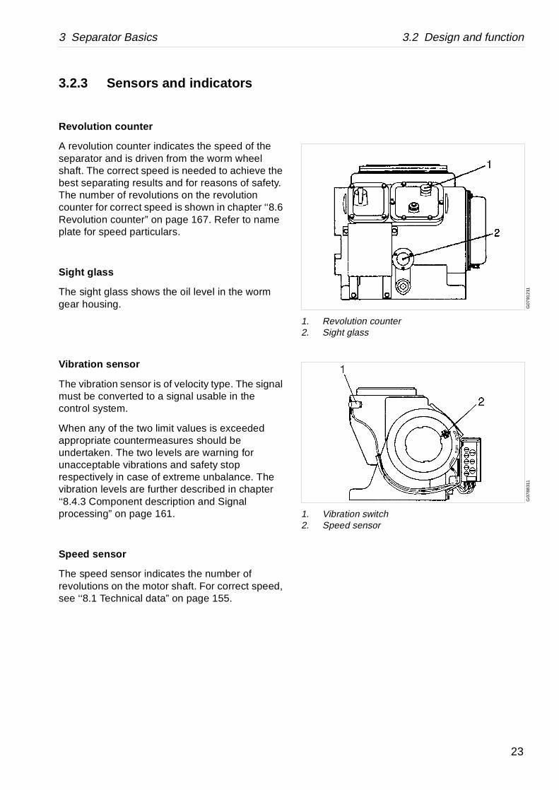
1. Revolution counter2. Sight glass
G07
8831
1
1. Vibration switch2. Speed sensor
3.2.3 Sensors and indicators
Revolution c ounter
A revolution counter indicates the speed of the separator and is driven from the worm wheel shaft. The correct speed is needed to achieve the best separating results and for reasons of safety. The number of revolutions on the revolution counter for correct speed is shown in chapter ‘‘8.6 Revolution counter” on page 167. Refer to name plate for speed particulars.
Sight glass
The sight glass shows the oil level in the worm gear housing.
Vibration sensor
The vibration sensor is of velocity type. The signal must be converted to a signal usable in the control system.
When any of the two limit values is exceeded appropriate countermeasures should be undertaken. The two levels are warning for unacceptable vibrations and safety stop respectively in case of extreme unbalance. The vibration levels are further described in chapter ‘‘8.4.3 Component description and Signal processing” on page 161.
Speed sensor
The speed sensor indicates the number of revolutions on the motor shaft. For correct speed, see ‘‘8.1 Technical data” on page 155.
23
3.2 Design and function 3 Separator Basics
G0
559
641
G0
5772
11
Paring disc
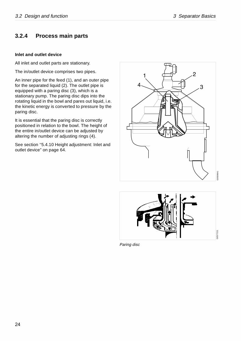
3.2.4 Process main parts
Inlet and outlet device
All inlet and outlet parts are stationary.
The in/outlet device comprises two pipes.
An inner pipe for the feed (1), and an outer pipe for the separated liquid (2). The outlet pipe is equipped with a paring disc (3), which is a stationary pump. The paring disc dips into the rotating liquid in the bowl and pares out liquid, i.e. the kinetic energy is converted to pressure by the paring disc.
It is essential that the paring disc is correctly positioned in relation to the bowl. The height of the entire in/outlet device can be adjusted by altering the number of adjusting rings (4).
See section ‘‘5.4.10 Height adjustment: Inlet and outlet device” on page 64.
24
3 Separator Basics 3.2 Design and function
G0
7964
B1
G0
796
4A1
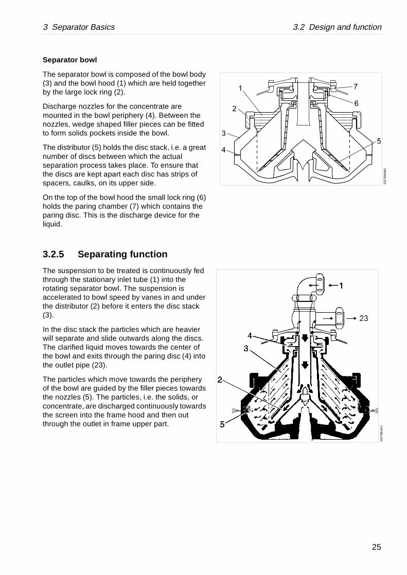
Separator bowl
The separator bowl is composed of the bowl body (3) and the bowl hood (1) which are held together by the large lock ring (2).
Discharge nozzles for the concentrate are mounted in the bowl periphery (4). Between the nozzles, wedge shaped filler pieces can be fitted to form solids pockets inside the bowl.
The distributor (5) holds the disc stack, i.e. a great number of discs between which the actual separation process takes place. To ensure that the discs are kept apart each disc has strips of spacers, caulks, on its upper side.
On the top of the bowl hood the small lock ring (6) holds the paring chamber (7) which contains the paring disc. This is the discharge device for the liquid.
3.2.5 Separating function
The suspension to be treated is continuously fed through the stationary inlet tube (1) into the rotating separator bowl. The suspension is accelerated to bowl speed by vanes in and under the distributor (2) before it enters the disc stack (3).
In the disc stack the particles which are heavier will separate and slide outwards along the discs. The clarified liquid moves towards the center of the bowl and exits through the paring disc (4) into the outlet pipe (23).
The particles which move towards the periphery of the bowl are guided by the filler pieces towards the nozzles (5). The particles, i.e. the solids, or concentrate, are discharged continuously towards the screen into the frame hood and then out through the outlet in frame upper part.
25
3.3 Definitions 3 Separator Basics
ator outlet.
n with the intention of separating lids, from a liquid having a lower les.
. Expressed in kg/m3 at specified at 15 °C.
bowl and inlet/outlet. Renewal of let.
lete separator, including bottom part d in an Intermediate Service, if any). bearings in bottom part.
a liquid.
quid to the separator per time unit.litre/h.
st movement. Normally expressed in 2/second), at specified temperature.
3.3 DefinitionsBack pressure Pressure in the separ
Clarification Liquid/solids separatioparticles, normally sodensity than the partic
Counter pressure See Back pressure.
Density Mass per volume unittemperature, normally
Intermediate Service (IS) Overhaul of separatorseals in bowl inlet/out
Major Service (MS) Overhaul of the comp(and activities includeRenewal of seals and
Sediment (sludge) Solids separated from
Throughput The feed of process liExpressed in m3/h or
Viscosity Fluid resistance againcentistoke (cSt = mm
26
4 Operating Instructions
Contents
4.1 Operating routine 29
4.2 Before first start 29
4.3 Ready for start 30
4.4 Start 31
4.5 Running 32
4.6 Normal stop 33
4.7 Emergency stop 34
27

28

4 Operating Instructions 4.1 Operating routine
G0
2620
11
Fill oil in the gear housing
4.1 Operating routineThese operating instructions are related only to the separator itself. If the separator is a part of a system or module follow also the instructions for the system.
4.2 Before first startTechnical demands for connections and logical limitations for the separator is described in the chapter ‘‘8 Technical Reference” on page 153 in the documents:
• Technical data
• Connection list
• Interface description
• Basic size drawing
• Foundation drawing
Before first start the following check points shall be checked:
1. Ensure the machine is installed correctly and that feed-lines and drains have been flushed clean.
2. Fill oil in the gear housing, see ‘‘5.7 When changing oil” on page 71.
3. Fill up exactly to the middle of the sightglass. Use the correct grade of oil. The separator is delivered without oil in the worm gear housing. For grade and quality, see ‘‘8.9 Lubricants” on page 171.
4. Select suitable nozzle diameter. See ‘‘8.5 Outlet nozzles” on page 166.
29

4.3 Ready for start 4 Operating Instructions
S0
0098
21
Check for leakages (not admitted)
G0
2620
11
Check the oil level
G05
2011
1
Release the brake
4.3 Ready for startTo achieve the best separation results the bowl should be in a clean condition.
1. Make sure that the nozzle diameter suits the process liquid to be treated. See nozzle capacities in ‘‘8.5 Outlet nozzles” on page 166.
2. Check that the bolts of the frame hood are fully tightened.
3. Check that all inlet and outlet connections have been correctly made and properly tightened.
4. Check that the oil level is exactly in the middle of the sight glass.
Fill if necessary, see ‘‘5.7 When changing oil” on page 71. See also chapter ‘‘8.9 Lubricants” on page 171, for a list of recommended oils.
5. Make sure that the brake is released.
CAUTION
Burn hazards
Make sure that hose connections and flange couplings are properly assembled and tightened.
Escaping hot liquid can cause severe burns.
NOTE
During running the oil level should be slightly below the middle of the sight glass.
Too much or too little oil can damage the separator bearings.
30

4 Operating Instructions 4.4 Start
G0
2462
11
Check for correct direction of rotation
S0
0556
11
Check for vibration
4.4 Start1. Start the separator.
2. Fill the bowl with safety/back up liquid. The flow must be 110% of the nozzle capacity. See ‘‘8.5 Outlet nozzles” on page 166.If the bowl and nozzles are perfectly cleaned, it is possible to start without flow.
3. Check the direction of rotation of the bowl. The revolution counter must turn clockwise.
4. Check the separator for vibration. Some vibration can occur for short periods during the starting cycle, when the separator passes through its critical speeds. This is normal and passes without danger. Try to learn the vibration characteristics of the critical speed pattern.
In the trouble-tracing chapter ‘‘7 Trouble-Tracing” on page 147, a number of causes are described that can create vibration.
DANGER
Disintegration hazards
When power cables have been connected, always check direction of rotation. If incorrect, vital rotating parts could unscrew.
DANGER
Disintegration hazards
When excessive vibration occurs, keep bowl filled and stop separator.
The cause of the vibration must be identified and rectified before the separator is restarted. Excessive vibration may be due to incorrect assembly or insufficient cleaning of the bowl.
31

4.5 Running 4 Operating Instructions
5. When the machine has reached full speed replace the safety/back up liquid gradually with process liquid.
4.5 Running
During operation, check
• oil level,
• speed,
• power consumption,
• throughput.
For daily condition checks, see ‘‘5.2.1 Daily checks” on page 41.
DANGER
Disintegration hazard
During start, separation and stop the bowl must be kept filled. If the feed of process liquid is interrupted supply safety/back up liquid instead.
DANGER
Disintegration hazard
During separation and as long as the bowl is rotating, the liquid feed must exceed the output from the nozzles.
32
4 Operating Instructions 4.6 Normal stop
S00
5111
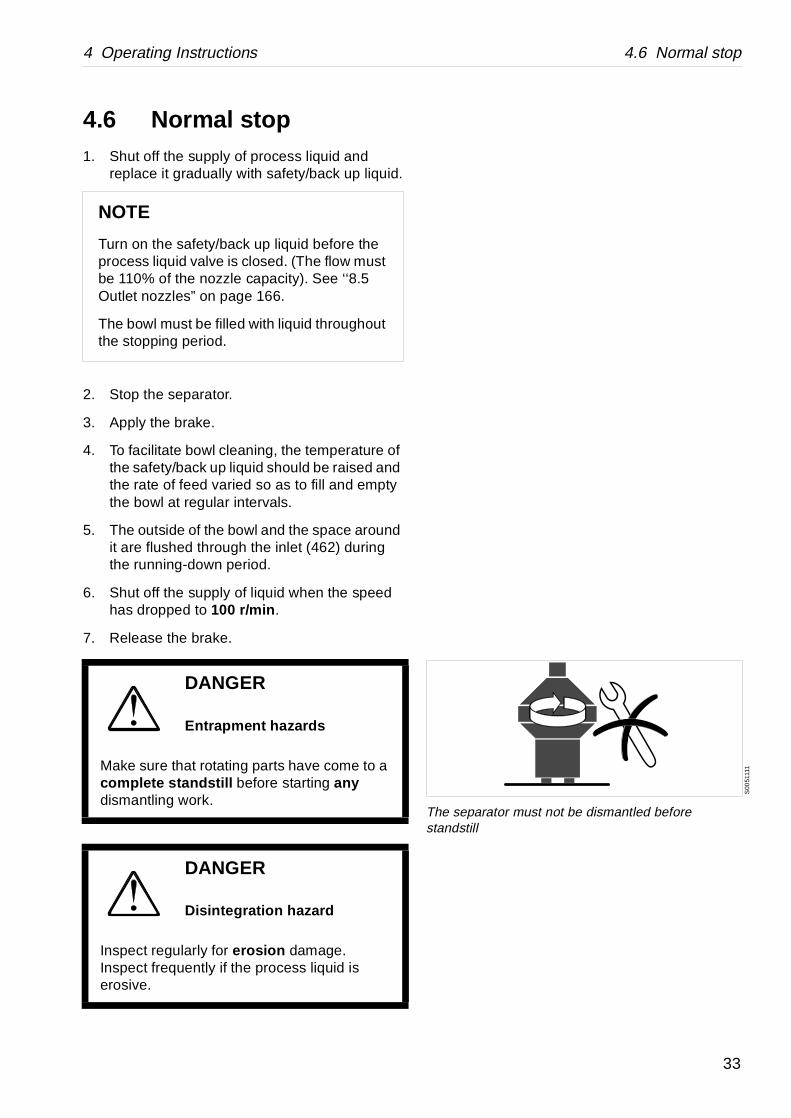
1
The separator must not be dismantled before standstill
4.6 Normal stop1. Shut off the supply of process liquid and
replace it gradually with safety/back up liquid.
2. Stop the separator.
3. Apply the brake.
4. To facilitate bowl cleaning, the temperature of the safety/back up liquid should be raised and the rate of feed varied so as to fill and empty the bowl at regular intervals.
5. The outside of the bowl and the space around it are flushed through the inlet (462) during the running-down period.
6. Shut off the supply of liquid when the speed has dropped to 100 r/min .
7. Release the brake.
NOTE
Turn on the safety/back up liquid before the process liquid valve is closed. (The flow must be 110% of the nozzle capacity). See ‘‘8.5 Outlet nozzles” on page 166.
The bowl must be filled with liquid throughout the stopping period.
DANGER
Entrapment hazards
Make sure that rotating parts have come to a complete standstill before starting any dismantling work.
DANGER
Disintegration hazard
Inspect regularly for erosion damage. Inspect frequently if the process liquid is erosive.
33
4.7 Emergency stop 4 Operating Instructions
S0
0511
11
The separator must not be dismantled before standstill
S00
0991
1
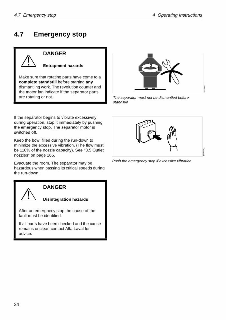
Push the emergency stop if excessive vibration
4.7 Emergency stop
If the separator begins to vibrate excessively during operation, stop it immediately by pushing the emergency stop. The separator motor is switched off.
Keep the bowl filled during the run-down to minimize the excessive vibration. (The flow must be 110% of the nozzle capacity). See ‘‘8.5 Outlet nozzles” on page 166.
Evacuate the room. The separator may be hazardous when passing its critical speeds during the run-down.
DANGER
Entrapment hazards
Make sure that rotating parts have come to a complete standstill before starting any dismantling work. The revolution counter and the motor fan indicate if the separator parts are rotating or not.
DANGER
Disintegration hazards
After an emergnecy stop the cause of the fault must be identified.
If all parts have been checked and the cause remains unclear, contact Alfa Laval for advice.
34
5 Periodic maintenance
Contents
5.1 Introduction 37
5.1.1 Maintenance intervals 37
5.1.2 Maintenance procedure 39
5.1.3 Service kits 40
5.2 Maintenance Logs 41
5.2.1 Daily checks 41
5.2.2 Oil change 41
5.2.3 Intermediate Service (IS) 42
5.2.4 Major Service (MS) 44
5.2.5 3-year Service (3S) 46
5.3 Check points at Intermediate Service (IS) 47
5.3.1 Corrosion 47
5.3.2 Cracks 49
5.3.3 Erosion 50
5.3.4 Spindle top and bowl body nave 51
5.3.5 Lock ring, bowl hood and bowl body 52
5.3.6 Thread check and repairing 53
5.3.7 Checking of alignment marks 56
5.3.8 Disc stack pressure 58
5.3.9 Worm wheel and worm; wearof teeth 59
5.3.10 Nozzle wear 59
5.4 Check points at Major Service (MS) 60
5.4.1 Bowl spindle; radial wobble 60
5.4.2 Brake 61
5.4.3 Corrosion 62
5.4.4 Cracks 62
5.4.5 Disc stack pressure 62
5.4.6 Erosion 63
5.4.7 Worm wheel and worm; wear of teeth 63
5.4.8 Worm wheel shaft; radial wobble 63
5.4.9 Top bearing springs and ball bearing housing 64
5.4.10 Height adjustment: Inlet and outlet device 64
5.4.11 Adjustment of speed sensor gap 65
5.5 Lifting instructions 66
5.5.1 Separator 66
5.5.2 Other parts 67
5.6 Cleaning 68
5.6.1 External cleaning 68
5.6.2 Cleaning agents 69
5.6.3 Cleaning of bowl discs 70
5.7 When changing oil 71
5.7.1 Worm wheel and worm; wear of teeth 71
5.7.2 Oil change procedure 74
5.8 Vibration 75
5.8.1 Vibration analysis 75
5.9 Common maintenance direc tions 76
5.9.1 Balancing of bowl 76
5.9.2 Ball and roller bearings 76
5.9.3 Before shutdowns 79
35

36
5 Periodic maintenance 5.1 Introduction
5.1 IntroductionPeriodic (preventive) maintenance reduces the risk of unexpected stoppages and breakdowns. Follow the maintenance logs on the following pages in order to facilitate the periodic maintenance.
5.1.1 Maintenance intervals
The following directions for periodic maintenance give a brief description of which parts to be cleaned, checked and renewed at different maintenance intervals.
The maintenance logs for each maintenance interval later in this chapter give detailed enumeration of the check points that must be done.
Daily checks consist of minor check points to carry out for detecting abnormal operating conditions.
Oil change
The oil change interval is every 2000 hours or at least once every year if the total number of operating hours is less than 2000 hours .
DANGER
Disintegration hazards
Separator parts that are either worn beyond their safe limits or incorrectly assembled may cause severe damage or fatal injury.
37
5.1 Introduction 5 Periodic maintenance
e schedule
3rd year
MS
S IS IS IS
3S
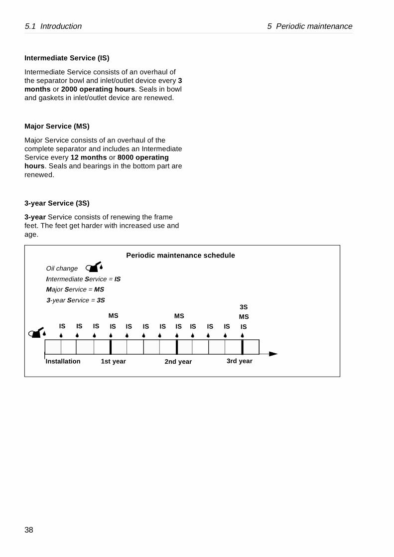
Intermediate Service (IS)
Intermediate Service consists of an overhaul of the separator bowl and inlet/outlet device every 3 months or 2000 operating hours . Seals in bowl and gaskets in inlet/outlet device are renewed.
Major Service (MS)
Major Service consists of an overhaul of the complete separator and includes an Intermediate Service every 12 months or 8000 operating hours . Seals and bearings in the bottom part are renewed.
3-year Service (3S)
3-year Service consists of renewing the frame feet. The feet get harder with increased use and age.
2nd year
Oil change
Intermediate Service = IS
Major Service = MS
Periodic maintenanc
Installation 1st year
MS MS
IS IS IS IS IS IS IS IS I
3-year Service = 3S
38

5 Periodic maintenance 5.1 Introduction
5.1.2 Maintenance procedure
At each Intermediate and Major Service, take a copy of the maintenance log and use it for notations during the service.
An Intermediate and Major Service should be carried out in the following manner:
1. Dismantle the parts as mentioned in the maintenance log and described in chapter ‘‘6 Dismantling/Assembly” on page 81.
Place the separator parts on clean, soft surfaces such as pallets.
2. Inspect and clean the dismantled separator parts according to the maintenance log.
3. Fit all the parts delivered in the service kit while assembling the separator as described in chapter ‘‘6 Dismantling/Assembly” on page 81. The assembly instructions have references to check points which should be carried out before and during the assembly.
DANGER
Disintegration hazards
No modifications are to be made to any part of the separator by machining or any other means as this can affect material strength or alter the fine tolerances necessary for safe operation.
DANGER
Disintegration hazards
Worn, eroded or improperly assembled machine parts may cause severe damage. Follow maintenance instructions and check for possible damage.
39
5.1 Introduction 5 Periodic maintenance
S0
021
021
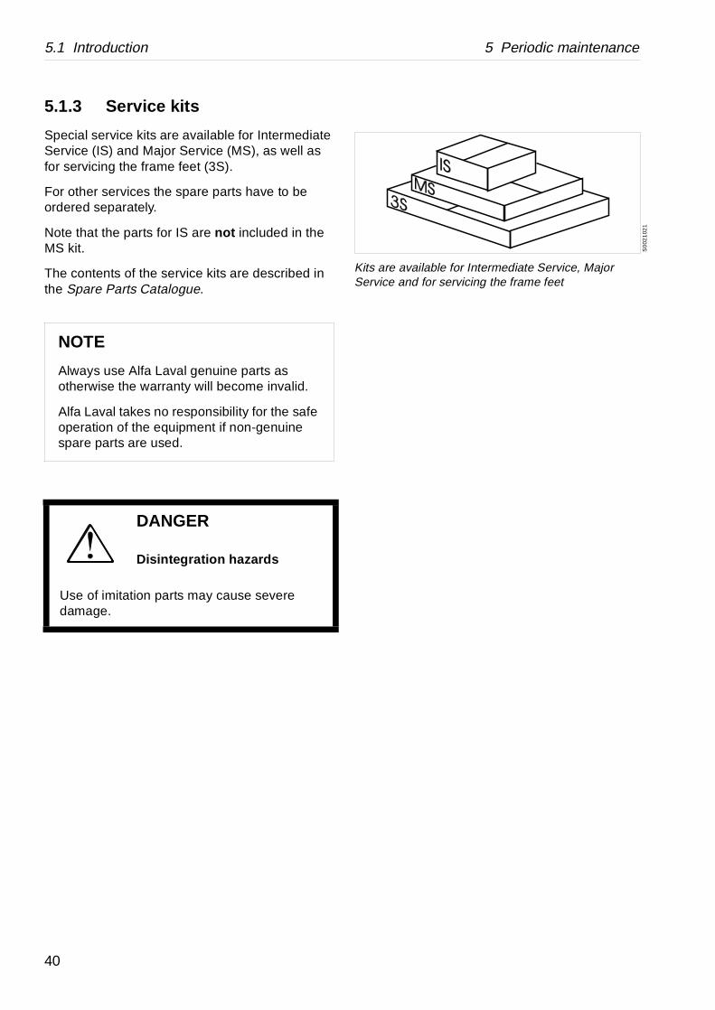
Kits are available for Intermediate Service, Major Service and for servicing the frame feet
5.1.3 Service kits
Special service kits are available for Intermediate Service (IS) and Major Service (MS), as well as for servicing the frame feet (3S).
For other services the spare parts have to be ordered separately.
Note that the parts for IS are not included in the MS kit.
The contents of the service kits are described in the Spare Parts Catalogue.
NOTE
Always use Alfa Laval genuine parts as otherwise the warranty will become invalid.
Alfa Laval takes no responsibility for the safe operation of the equipment if non-genuine spare parts are used.
DANGER
Disintegration hazards
Use of imitation parts may cause severe damage.
40
5 Periodic maintenance 5.2 Maintenance Logs
Page Notes
ing housing –
75
in gear housing 74
1)
Page Notes
heel and worm 71
ear housing 74
5.2 Maintenance Logs
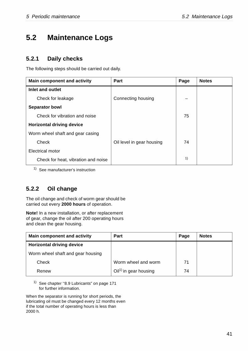
5.2.1 Daily checks
The following steps should be carried out daily.
5.2.2 Oil change
The oil change and check of worm gear should be carried out every 2000 hours of operation.
Note! In a new installation, or after replacement of gear, change the oil after 200 operating hours and clean the gear housing.
1) See chapter ‘‘8.9 Lubricants” on page 171 for further information.
When the separator is running for short periods, the lubricating oil must be changed every 12 months even if the total number of operating hours is less than 2000 h.
1) See manufacturer’s instruction
Main component and activity Part
Inlet and outlet
Check for leakage Connect
Separator bowl
Check for vibration and noise
Horizontal driving device
Worm wheel shaft and gear casing
Check Oil level
Electrical motor
Check for heat, vibration and noise
Main component and activity Part
Horizontal driving device
Worm wheel shaft and gear housing
Check Worm w
Renew Oil1) in g
41

5.2 Maintenance Logs 5 Periodic maintenance
Local identification:
Manufacture No./Year:
Product No: 881119-01-03
Signature:
Page Notes
g house –
d sealings –
53
–
68
–
nave 51
52
nd holders 59
47
49
50
pressure 62
d sealings –
le taper 51
el and worm 71
housing 74
lug packing 102
n motor –
5.2.3 Intermediate Service (IS)
Name of plant:
Separator: CH/FESX 512S-35CG
Total running hours:
Date:
Main component and activity Part
Inlet and outlet
Clean and inspect Connectin
Renew O-rings an
Separator bowl
Clean and check Lock rings
Bowl hood
Bowl discs
Distributor
Bowl body
Bowl body
Nozzles a
Check Corrosion
Cracks
Erosion
Disc stack
Renew O-rings an
Vertical driving device
Clean and check Bowl spind
Horizontal driving device
Worm wheel shaft and gear housing
Check Worm whe
Renew Oil in gear
Oil drain p
Electrical motor
Lubrication (if nipples are fitted) See sign o
42
5 Periodic maintenance 5.2 Maintenance Logs
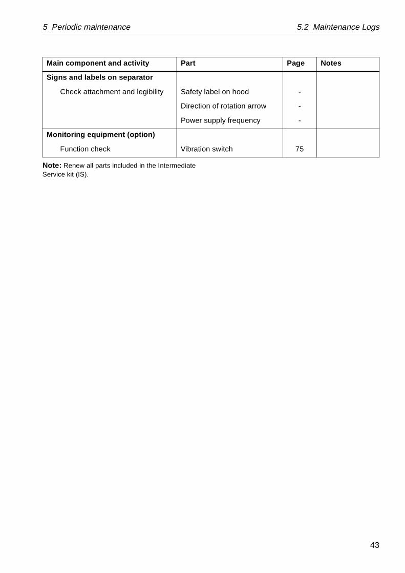
el on hood -
f rotation arrow -
ply frequency -
witch 75
Page Notes
Note: Renew all parts included in the Intermediate Service kit (IS).
Signs and labels on separator
Check attachment and legibility Safety lab
Direction o
Power sup
Monitoring equipment (option)
Function check Vibration s
Main component and activity Part
43
5.2 Maintenance Logs 5 Periodic maintenance
Local identification:
Manufacture No./Year:
Product No: 881119-01-03
Signature:
Page Notes
g house –
d sealings –
56
–
68
–
nave 51
52
nd holders 59
47
49
50
pressure 62
d sealings –
le taper 51
ings and ball using
64
bble of bowl spindle 60
arings, O-rings r buffers
76, 106
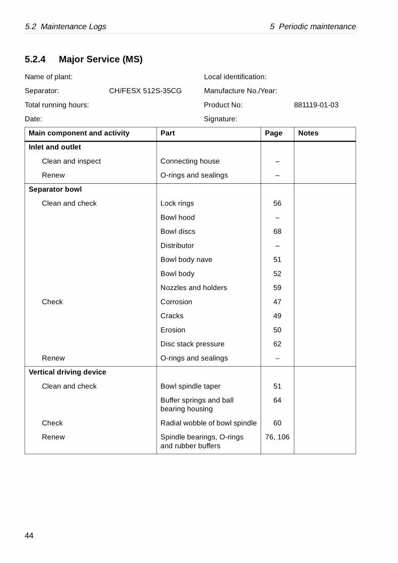
5.2.4 Major Service (MS)
Name of plant:
Separator: CH/FESX 512S-35CG
Total running hours:
Date:
Main component and activity Part
Inlet and outlet
Clean and inspect Connectin
Renew O-rings an
Separator bowl
Clean and check Lock rings
Bowl hood
Bowl discs
Distributor
Bowl body
Bowl body
Nozzles a
Check Corrosion
Cracks
Erosion
Disc stack
Renew O-rings an
Vertical driving device
Clean and check Bowl spind
Buffer sprbearing ho
Check Radial wo
Renew Spindle beand rubbe
44
5 Periodic maintenance 5.2 Maintenance Logs
el and worm 71
bble of worm wheel 63
O-rings, sealings 76
housing 74
d brake shoe 61
d 61
n motor –
el on hood -
f rotation arrow -
ply frequency -
witch 75
sor
Page Notes
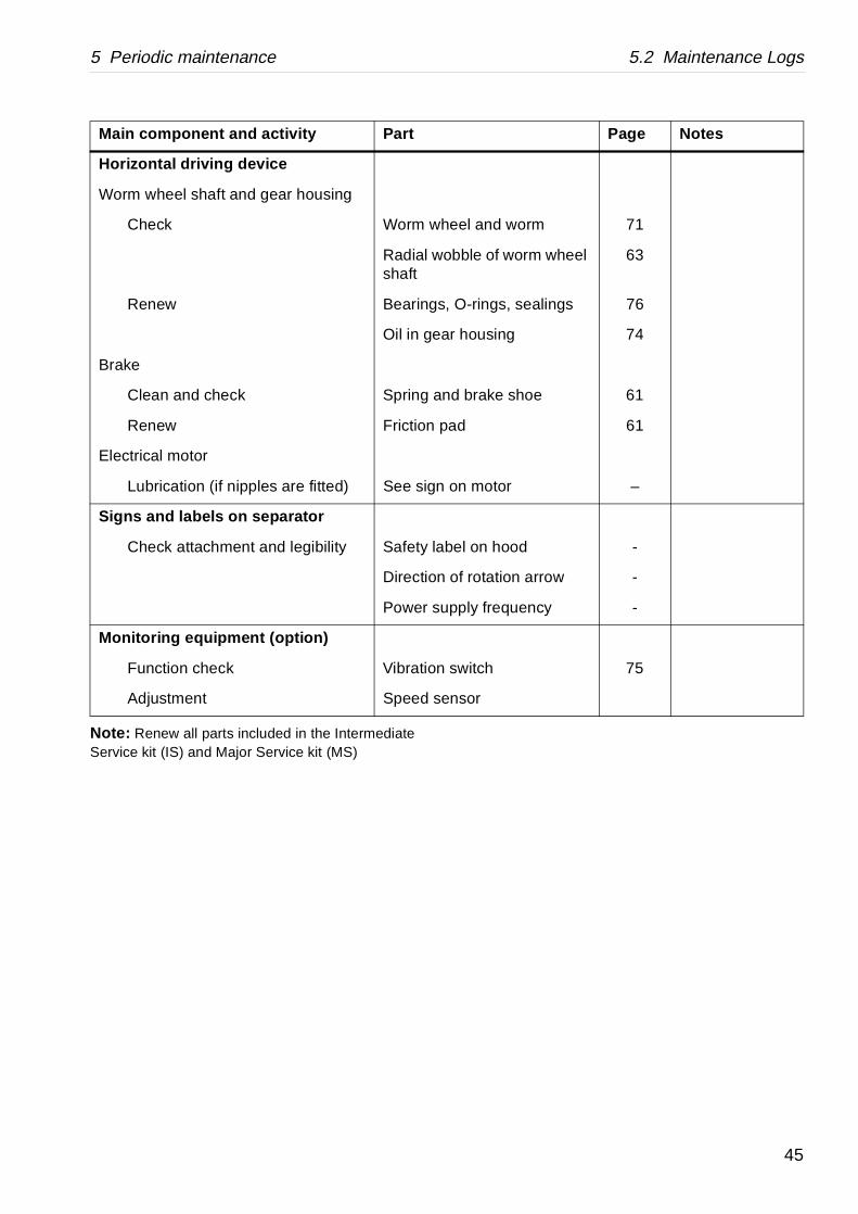
Note: Renew all parts included in the Intermediate Service kit (IS) and Major Service kit (MS)
Horizontal driving device
Worm wheel shaft and gear housing
Check Worm whe
Radial woshaft
Renew Bearings,
Oil in gear
Brake
Clean and check Spring an
Renew Friction pa
Electrical motor
Lubrication (if nipples are fitted) See sign o
Signs and labels on separator
Check attachment and legibility Safety lab
Direction o
Power sup
Monitoring equipment (option)
Function check Vibration s
Adjustment Speed sen
Main component and activity Part
45

5.2 Maintenance Logs 5 Periodic maintenance
5.2.5 3-year Service (3S)
Renew the frame feet as described in ‘‘6.9 Frame feet” on page 143. The 3-year service should be carried out in conjunction with a Major Service (MS). The extent of the 3-year service is the same as for a major service plus renewing the parts included in the 3-year Service kit (3S).
46

5 Periodic maintenance 5.3 Check points at Intermediate Service (IS)
G03
4824
1S
002
061
1
5.3 Check points at Intermediate Service (IS)
5.3.1 Corrosion
Evidence of corrosion attacks should be looked for and rectified each time the separator is dismantled. Main bowl parts such as the bowl body, bowl hood and lock ring must be inspected with particular care for corrosion damage.
Always contact your Alfa Laval representative if you suspect that the largest depth of the corrosion damage exceeds 1,0 mm or if cracks have been found. Do not continue to use the separator until it has been inspected and given clearance for operation by Alfa Laval.
Cracks or damage forming a line should be considered as being particularly hazardous.
Non-s tainless steel and cast iron parts
Corrosion (rusting) can occur on unprotected surfaces of non-stainless steel and cast iron. Frame parts can corrode when exposed to an aggressive environment.
Stainless steel
Stainless steel parts corrode when in contact with either chlorides or acidic solutions. Acidic solutions causes a general corrosion. The chloride corrosion is characterised by local damage such as pitting, grooves or cracks.
DANGER
Disintegration hazard
Inspect regularly for corrosion damage. Inspect frequently if the process liquid is corrosive.
47
5.3 Check points at Intermediate Service (IS) 5 Periodic maintenance
S0
0205
11
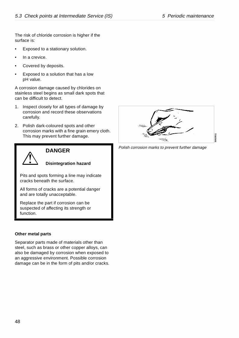
Polish corrosion marks to prevent further damage
S0
0205
11
The risk of chloride corrosion is higher if the surface is:
• Exposed to a stationary solution.
• In a crevice.
• Covered by deposits.
• Exposed to a solution that has a low pH value.
A corrosion damage caused by chlorides on stainless steel begins as small dark spots that can be difficult to detect.
1. Inspect closely for all types of damage by corrosion and record these observations carefully.
2. Polish dark-coloured spots and other corrosion marks with a fine grain emery cloth. This may prevent further damage.
Other me tal parts
Separator parts made of materials other than steel, such as brass or other copper alloys, can also be damaged by corrosion when exposed to an aggressive environment. Possible corrosion damage can be in the form of pits and/or cracks.
DANGER
Disintegration hazard
Pits and spots forming a line may indicate cracks beneath the surface.
All forms of cracks are a potential danger and are totally unacceptable.
Replace the part if corrosion can be suspected of affecting its strength or function.
48

5 Periodic maintenance 5.3 Check points at Intermediate Service (IS)
5.3.2 Cracks
Cracks can initiate on the machine after a period of operation and propagate with time.
• Cracks often initiate in an area exposed to high cyclic material stresses. These are called fatigue cracks.
• Cracks can also initiate due to corrosion in an aggressive environment.
• Although very unlikely, cracks may also occur due to the low temperature embrittlement of certain materials.
The combination of an aggressive environment and cyclic stresses will speed-up the formation of cracks. Keeping the machine and its parts clean and free from deposits will help to prevent corrosion attacks.
It is particularly important to inspect for cracks in rotating parts and especially the pillars between the sludge ports in the bowl wall.
Always contact your Alfa Laval representative if you suspect that the largest depth of the damage exceeds 1,0 mm . Do not continue to use the separator until it has been inspected and cleared for operation by Alfa Laval.
DANGER
Disintegration hazard
All forms of cracks are potentially dangerous as they reduce the strength and functional ability of components.
Always replace a part if cracks are present.
49
5.3 Check points at Intermediate Service (IS) 5 Periodic maintenance
e thickness of the metal.ffecting its strength or function.
G02
0522
1G
079
6731
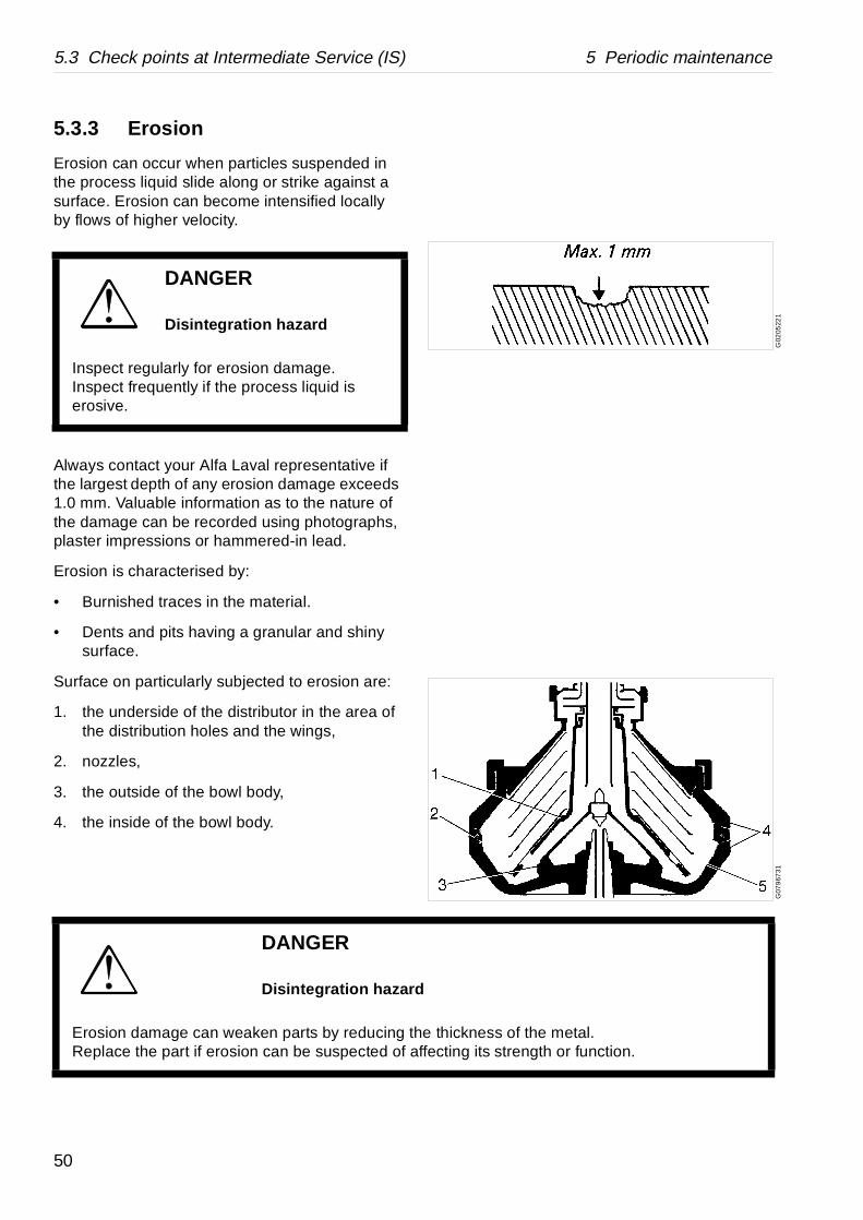
5.3.3 Erosion
Erosion can occur when particles suspended in the process liquid slide along or strike against a surface. Erosion can become intensified locally by flows of higher velocity.
Always contact your Alfa Laval representative if the largest depth of any erosion damage exceeds 1.0 mm. Valuable information as to the nature of the damage can be recorded using photographs, plaster impressions or hammered-in lead.
Erosion is characterised by:
• Burnished traces in the material.
• Dents and pits having a granular and shiny surface.
Surface on particularly subjected to erosion are:
1. the underside of the distributor in the area of the distribution holes and the wings,
2. nozzles,
3. the outside of the bowl body,
4. the inside of the bowl body.
DANGER
Disintegration hazard
Inspect regularly for erosion damage. Inspect frequently if the process liquid is erosive.
DANGER
Disintegration hazard
Erosion damage can weaken parts by reducing thReplace the part if erosion can be suspected of a
50

5 Periodic maintenance 5.3 Check points at Intermediate Service (IS)
G0
3488
21G
078
9411
5.3.4 Spindle top and bowl body nave
Impact marks on the spindle cone or in the bowl body nave can cause the separator to vibrate when running.
Rust can cause the bowl to stick firmly to the spindle cone and make dismantling very difficult.
Both the spindle top and the bowl nave should be carefully inspected if the cartridge has been dismantled or if the bowl runs roughly.
1. Clean the bowl body nave and the spindle taper with a suitable degreasing agent.
2. Remove any impact marks with a scraper and/or whetstone.
3. Remove any rust by using a fine-grain emery cloth of approximately 320 grade.
4. Finish with polishing paper of approximately 600 grade.
5. Whenever fitting the bowl body on the spindle first apply a few drops of oil to the spindle cone for corrosion protection reasons and then wipe it with a clean cloth.
NOTE
Always use the scraper with great care. The conicity must not be marred.
51
5.3 Check points at Intermediate Service (IS) 5 Periodic maintenance
G03
4224
1G
0348
421
G03
4873
1
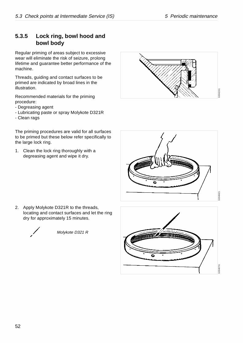
5.3.5 Lock ring, bowl hood and bowl body
Regular priming of areas subject to excessive wear will eliminate the risk of seizure, prolong lifetime and guarantee better performance of the machine.
Threads, guiding and contact surfaces to be primed are indicated by broad lines in the illustration.
Recommended materials for the priming procedure:- Degreasing agent- Lubricating paste or spray Molykote D321R- Clean rags
The priming procedures are valid for all surfaces to be primed but these below refer specifically to the large lock ring.
1. Clean the lock ring thoroughly with a degreasing agent and wipe it dry.
2. Apply Molykote D321R to the threads, locating and contact surfaces and let the ring dry for approximately 15 minutes.
Molykote D321 R
52

5 Periodic maintenance 5.3 Check points at Intermediate Service (IS)
G0
348
421
G03
487
31G
079
681
1
3. Polish the Molykote into the surface with a clean rag. The black spray should look like well-polished black shoe cream when properly performed.
4. Apply Molykote D321R to the same surfaces of the lock ring a second time and let it dry for approximately 15 minutes.
5. Repeat the polishing procedure as above.
6. Proceed in the same way with the threads of the bowl body and the locating surfaces and threads of the bowl hood.
5.3.6 Thread check and repairing
1. Inspect the threads for burrs and protrusions caused by impact.
Molykote D321 R
CAUTION
Cut hazard
The lock ring threads may have sharp edges which can cause cuts.
53
5.3 Check points at Intermediate Service (IS) 5 Periodic maintenance
G0
3486
21G
079
6821
G0
7968
31
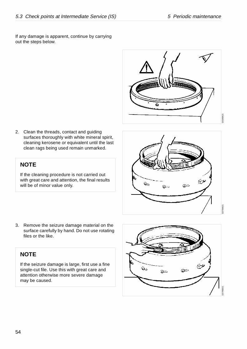
If any damage is apparent, continue by carrying out the steps below.
2. Clean the threads, contact and guiding surfaces thoroughly with white mineral spirit, cleaning kerosene or equivalent until the last clean rags being used remain unmarked.
3. Remove the seizure damage material on the surface carefully by hand. Do not use rotating files or the like.
NOTE
If the cleaning procedure is not carried out with great care and attention, the final results will be of minor value only.
NOTE
If the seizure damage is large, first use a fine single-cut file. Use this with great care and attention otherwise more severe damage may be caused.
54

5 Periodic maintenance 5.3 Check points at Intermediate Service (IS)
G07
9684
1G
079
682
1
4. To smooth off the edges and to remove any burnt-in impurities, use a whetstone or a fine-grain emery cloth of approximately 240 grade.
5. Finish the repair by polishing the damage spot with a soft, clean rag and brush wax. It is recommended that the whole area where seizure damage may occur be polished.
The polishing will smooth out the complete damage and even out the deepest parts.
6. Proceed in the same way with the large lock ring threads.
55

5.3 Check points at Intermediate Service (IS) 5 Periodic maintenance
G03
482
41G
0348
251
G0
7734
71
5.3.7 Checking of alignment marks
The relative positions of the alignment marks on the bowl hood and the large lock ring give a good indication of the amount of thread wear present, if an extra disc should be added or one removed, or when maintenance is required.
1. Remove the large lock ring and the bowl hood.
2. Remove a number of bowl discs from the disc stack to make sure that no disc stack pressure will be present in the following, or lift out the distributor with the whole disc stack.
3. Replace the bowl hood without the O-ring.
Make sure that the bowl hood is properly centered and aligned in the bowl body.
DANGER
Disintegration hazard
Wear on large lock ring thread must not exceed safety limit.
φ-mark on lock ring must not pass opposite φ-mark by more than the specified distance.
NOTE
The following procedure must only be performed when all parts have been cleaned, any damages remedied and surfaces lubricated according to lubrication instructions.
56

5 Periodic maintenance 5.3 Check points at Intermediate Service (IS)
G0
391
921
G0
392
121
4. Screw the large lock ring onto the bowl with the lock ring spanner. Tighten by hand only. Then strike lightly with a hammer, one or two blows to make sure that the parts butt against each other.
5. Note the position of the alignment marks (φ) and check the alternatives (a, b, c) below
When the threads are worn, tightening the lock ring will cause the alignment mark on the lock ring to pass beyond the mark on the bowl hood.
If the marks don’t align it might indicate that the parts are not properly engaged or not sufficiently cleaned.
a. In a new bowl, the alignment marks should be exactly opposite each other as shown in the illustration.
b. If the mark on the lock ring passes the mark on the bowl hood by less than 25°, a new alignment mark should be punched-in on the lock ring at the new position.
NOTE
Do not grind off the old mark but mark it in some way so that it cannot be mistaken for the new mark.
57

5.3 Check points at Intermediate Service (IS) 5 Periodic maintenance
G03
9224
1
25° corresponds to 100 mm
c. When the alignment mark on the lock ring passes the original alignment mark on the bowl hood by more than 25°, an Alfa Laval representative must be contacted immediately.
If the alignment marks are illegible, contact an Alfa Laval representative immediately for determination of the extent of thread wear and for the punching of new alignment marks.
5.3.8 Disc stack pressure
The lock ring should press the bowl hood firmly against the bowl body. The hood in turn should exert a pressure on the disc stack, clamping it in place.
1. Compress the disc stack by tightening the lock ring, see chapter ‘‘6.3.2 Assembly” on page 93.
NOTE
Ensure that the disc stack pressure is sufficient to maintain bowl balance.
Insufficient pressure in the disc stack can cause vibration and reduce lifetime of ball bearings.
58
5 Periodic maintenance 5.3 Check points at Intermediate Service (IS)
S0
119
031
S0
119
011
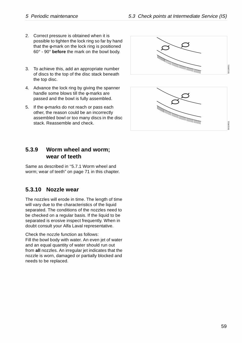
2. Correct pressure is obtained when it is possible to tighten the lock ring so far by hand that the φ-mark on the lock ring is positioned 60° - 90° before the mark on the bowl body.
3. To achieve this, add an appropriate number of discs to the top of the disc stack beneath the top disc.
4. Advance the lock ring by giving the spanner handle some blows till the φ-marks are passed and the bowl is fully assembled.
5. If the φ-marks do not reach or pass each other, the reason could be an incorrectly assembled bowl or too many discs in the disc stack. Reassemble and check.
5.3.9 Worm wheel and worm; wear of teeth
Same as described in ‘‘5.7.1 Worm wheel and worm; wear of teeth” on page 71 in this chapter.
5.3.10 Nozzle wear
The nozzles will erode in time. The length of time will vary due to the characteristics of the liquid separated. The conditions of the nozzles need to be checked on a regular basis. If the liquid to be separated is erosive inspect frequently. When in doubt consult your Alfa Laval representative.
Check the nozzle function as follows:Fill the bowl body with water. An even jet of water and an equal quantity of water should run out from all nozzles. An irregular jet indicates that the nozzle is worn, damaged or partially blocked and needs to be replaced.
59

5.4 Check points at Major Service (MS) 5 Periodic maintenance
G0
681
711
A. Max. 0,04 mm
G0
6818
21G
068
191
1
5.4 Check points at Major Service (MS)
5.4.1 Bowl spindle; radial wobble
Excessive wobble is indicated by rough bowl running.
Measure the wobble at the top of the spindle tapered end.
Maximum permissible radial wobble: 0,04 mm.
First check the wobble before dismounting the spindle. If wobble is too large: replace the top and bottom bearings.
Measure again the wobble after assembly. If it is still excessive, the spindle is probably damaged and must be replaced.
Check wobbling as a preventive measure each time the spindle and top bearing have been assembled.
During reading, the spindle must be revolved by hand using the coupling drum.
60

5 Periodic maintenance 5.4 Check points at Major Service (MS)
G06
8182
1G
013
411
1
5.4.2 Brake
A worn or oily friction pad will lengthen the braking period.
If the friction pad is worn:
1. Remove the brake cover.
2. Remove the screws and exchange the friction pad.
NOTE
The screws are slotted in both ends.
61
5.4 Check points at Major Service (MS) 5 Periodic maintenance
G0
1342
11
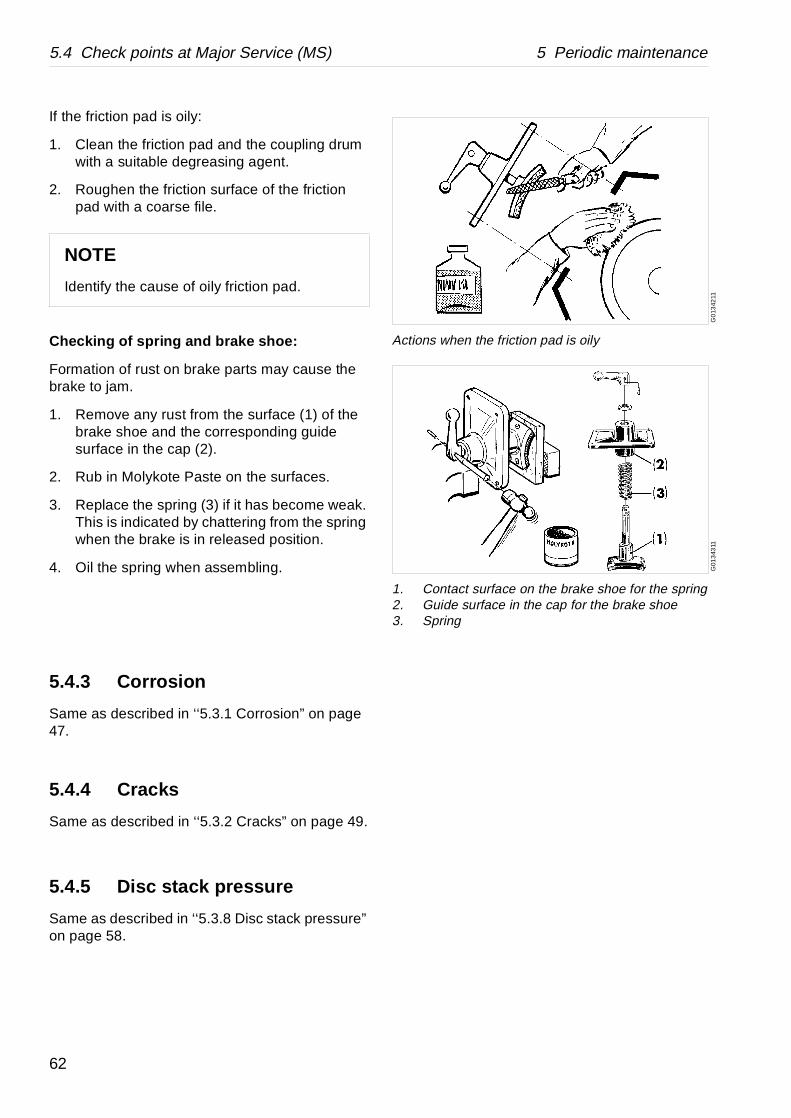
Actions when the friction pad is oily
G01
343
11
1. Contact surface on the brake shoe for the spring2. Guide surface in the cap for the brake shoe3. Spring
If the friction pad is oily:
1. Clean the friction pad and the coupling drum with a suitable degreasing agent.
2. Roughen the friction surface of the friction pad with a coarse file.
Checking of spring and brake shoe:
Formation of rust on brake parts may cause the brake to jam.
1. Remove any rust from the surface (1) of the brake shoe and the corresponding guide surface in the cap (2).
2. Rub in Molykote Paste on the surfaces.
3. Replace the spring (3) if it has become weak. This is indicated by chattering from the spring when the brake is in released position.
4. Oil the spring when assembling.
5.4.3 Corrosion
Same as described in ‘‘5.3.1 Corrosion” on page 47.
5.4.4 Cracks
Same as described in ‘‘5.3.2 Cracks” on page 49.
5.4.5 Disc stack pressure
Same as described in ‘‘5.3.8 Disc stack pressure” on page 58.
NOTE
Identify the cause of oily friction pad.
62
5 Periodic maintenance 5.4 Check points at Major Service (MS)
G0
246
131
5.4.6 Erosion
Same as described in ‘‘5.3.3 Erosion” on page 50.
5.4.7 Worm wheel and worm; wear of teeth
Same as described in section ‘‘5.7.1 Worm wheel and worm; wear of teeth” on page 71.
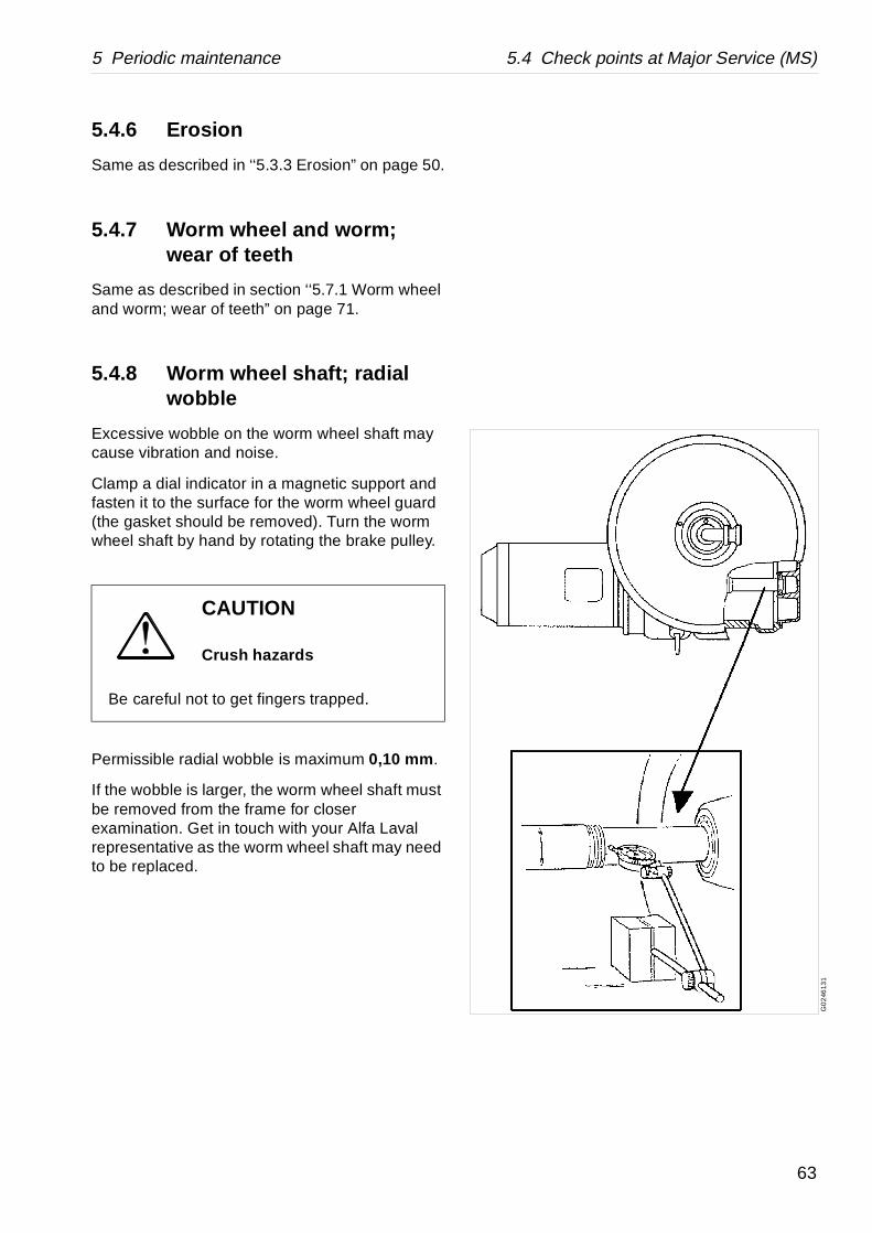
5.4.8 Worm wheel shaft; radial wobble
Excessive wobble on the worm wheel shaft may cause vibration and noise.
Clamp a dial indicator in a magnetic support and fasten it to the surface for the worm wheel guard (the gasket should be removed). Turn the worm wheel shaft by hand by rotating the brake pulley.
Permissible radial wobble is maximum 0,10 mm .
If the wobble is larger, the worm wheel shaft must be removed from the frame for closer examination. Get in touch with your Alfa Laval representative as the worm wheel shaft may need to be replaced.
CAUTION
Crush hazards
Be careful not to get fingers trapped.
63

5.4 Check points at Major Service (MS) 5 Periodic maintenance
G07
892
11
1. Radial buffer2. Buffer spring3. Ball bearing housing4. Axial buffer
G0
5650
21
5.4.9 Top bearing springs and ball bearing housing
Weakened or broken buffer springs as well as defective contact surfaces for the buffers on the ball bearing housing may give rise to machine vibration (rough bowl run).
Springs
It is difficult to determine the condition (stiffness) of a spring without special instrument. So, an estimation of the spring condition must be based on the experience of the machine run before the overhaul.
It is recommended, however, that all springs are replaced at the annual overhaul.
In case of sudden spring fracture, the complete set should be replaced even if only one spring is broken.
Ball bearing housing
Examine the contact surface for the buffers (1) on the ball bearing housing (3). In case of defects (indentations deeper than 0,1 mm ) replace the housing as well as buffers and springs.
5.4.10 Height adjustment: Inlet and outlet device
Check the position of the inlet/outlet device at the time intervals prescribed in the maintenance schedule and after the replacement or reassembling of parts that can affect the height position.
During the check, the large lock ring must be firmly tightened and the frame hood screws tightened.
The check is carried out by measuring the height of the gasket top surface on the frame hood relative that of the top of the wings in the paring chamber. See illustration.
If the measure is incorrect, remove or insert another gasket. A minimum of one and a maximum of five gaskets can be installed.
64

5 Periodic maintenance 5.4 Check points at Major Service (MS)
G0
2459
11
5.4.11 Adjustment of speed sensor gap
Incorrect speed sensor gap may cause faulty speed monitoring. For access to speed sensor, remove the brake cover.
The position of the speed sensor should be checked if the bowl spindle or the speed sensor has been dismantled or replaced.
• Adjust the gap between the speed sensor and the brake pulley. The gap is measured between two slots and should be 2 ±0,5 mm.
• Tighten the speed sensor with a torque of max. 50 Nm.
65

5.5 Lifting instructions 5 Periodic maintenance
G05
4311
1
5.5 Lifting instructions
5.5.1 Separator
Before lifting the separator remove following parts:• Inlet and outlet device• Top cover• Collecting cover• Bowl
Attach three endless slings or cables to the lifting eyes. There are two fixed lifting eyes on the frame top part and one to be mounted on the common foundation (the screw must be tightened with spanner.
A. Three endless slings
66

5 Periodic maintenance 5.5 Lifting instructions
5.5.2 Other parts
All heavy parts must be lifted by means of a hoist. Use endless lifting straps and a lifting hook with safety catch.
Special tools from the tool kit must be used for dismantling and assembly. The special tools are specified in the Spare Parts Catalogue.
NOTE
Machine weight without inlet/outlet device, top cover, collecting cover and bowl is approx. 1200 kg .
Weight of bowl: 320 kg
Weight of the covers: 50 kg together
WARNING
Crush hazards
Use only the special lifting eyes for lifting the machine. Two are fixed on the frame top part and one is to be mounted on the foundation. See illustration.
A falling separator can cause accidents resulting in serious injury to persons and damage to equipment.
NOTE
When lifting parts without weight specifications, always use lifting straps with the capacity of at least 500 kg .
67
5.6 Cleaning 5 Periodic maintenance
G0
5451
21
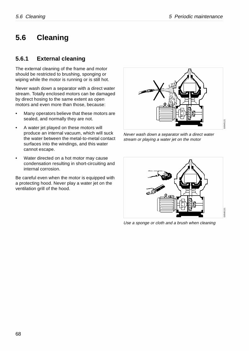
Never wash down a separator with a direct water stream or playing a water jet on the motor
G05
4513
1Use a sponge or cloth and a brush when cleaning
5.6 Cleaning
5.6.1 External cleaning
The external cleaning of the frame and motor should be restricted to brushing, sponging or wiping while the motor is running or is still hot.
Never wash down a separator with a direct water stream. Totally enclosed motors can be damaged by direct hosing to the same extent as open motors and even more than those, because:
• Many operators believe that these motors are sealed, and normally they are not.
• A water jet played on these motors will produce an internal vacuum, which will suck the water between the metal-to-metal contact surfaces into the windings, and this water cannot escape.
• Water directed on a hot motor may cause condensation resulting in short-circuiting and internal corrosion.
Be careful even when the motor is equipped with a protecting hood. Never play a water jet on the ventilation grill of the hood.
68

5 Periodic maintenance 5.6 Cleaning
5.6.2 Cleaning agents
When using chemical cleaning agents, make sure you follow the general rules and suppliers’ recommendations regarding ventilation, protection of personnel, etc.
For separator b owl, inlet and outlet
A chemical cleaning agent must dissolve the deposits quickly without attacking the material of the separator parts.
For parts of the driving devices
Use white spirit, cleaning-grade kerosene or diesel oil.
Oiling (protect surfaces against corrosion)
Protect cleaned carbon steel parts against corrosion by oiling. Separator parts that are not assembled after cleaning must be wiped and coated with a thin layer of clean oil and protected from dust and dirt.
CAUTION
Skin irritation hazard
Read the instructions on the label of the container before using the chemical cleaning agent.
Always wear safety goggles, gloves and protective clothing as the liquid is alkaline and dangerous to skin and eyes.
69

5.6 Cleaning 5 Periodic maintenance
G00
658
31
Put the discs one by one into the cleaning agent
G0
0658
41
Clean the discs with a soft brush
5.6.3 Cleaning of bowl discs
Handle the bowl discs carefully so as to avoid damage to the surfaces during cleaning.
1. Remove the bowl discs from the distributor and lay them down, one by one , in the cleaning agent.
2. Let the discs remain in the cleaning agent until the deposits have been dissolved. This will normally take between two and four hours.
3. Finally clean the discs with a soft brush.
NOTE
Mechanical cleaning is likely to scratch the disc surfaces causing deposits to form quicker and adhere more firmly.
A gentle chemical cleaning is therefore preferable to mechanical cleaning.
70

5 Periodic maintenance 5.7 When changing oil
G0
205
311
1. Worm2. Worm wheel
G0
2054
11
Check the gear ratio (number of teeth) when replacing the gear
5.7 When changing oil
5.7.1 Worm wheel and worm; wear of teeth
To check at each oil change
Check the teeth of both the worm wheel and worm for wear. Examine the contact surfaces and compare the tooth profiles with the ‘‘ Tooth appearance examples” on page 73. The gear may operate satisfactorily even when worn to some degree.
• Replace both worm wheel and worm at the same time, even if only one of them is worn.
• To avoid damaging the teeth when lifting the bowl spindle: push the worm wheel to one side first.
Position the spindle in correct place before fitting the worm wheel.
When replacing the gear, always make sure that the new worm wheel and worm have the same number of teeth as the old ones. See chapter ‘‘8.1 Technical data” on page 155 for correct number of teeth.
DANGER
Disintegration hazards
Check that gear ratio is correct for power frequency used. If incorrect, subsequent overspeed may result in a serious breakdown.
NOTE
Presence of metal chips in the oil bath is an indication that the gear is wearing abnormally.
71
5.7 When changing oil 5 Periodic maintenance
Important!
When using mineral-type oil in the worm gear housing, the presence of black deposits on the spindle parts is an indication that the oil base has deteriorated seriously or that some of the oil additives have precipitated. If pits are found on the worm gear, the cause could be that the additives are not suitable for this purpose.
In all these cases it is imperative to change to a high-temperature oil.
For further information, see chapter ‘‘8.9 Lubricants” on page 171.
72

5 Periodic maintenance 5.7 When changing oil
G05
3871
1
Satisfactory teeth
G05
388
11
Worn teeth
G0
5389
11
Spalling
G05
390
11
Pitting
Tooth appearance examples
Satisfactory teeth:
Uniform wear of contact surfaces. Surfaces are smooth.
Good contact surfaces will form on the teeth when the gear is subjected to only moderate load during its running-in period.
Worn teeth:
Permissible wear is as a rule 1/3 of the thickness of the upper part of a tooth, provided that
• the wear is uniform over the whole of the flank of a tooth
• and all teeth are worn in the same way.
Spalling :
Small bits of the teeth have broken off, so-called spalling. This is generally caused by excessive load or improper lubrication. Damage of this type need not necessitate immediate replacement, but careful checking at short intervals is of imperative importance.
Pitting:
Small cavities in the teeth, so-called pitting, can occur through excessive load or improper lubrication. Damage of this type need not necessitate immediate replacement, but careful check at short intervals is of imperative importance.
73

5.7 When changing oil 5 Periodic maintenance
G0
134
411
1. Oil filling plug2. Sight glass3. Oil drain plug
G0
4842
11
Burn hazards: The drained oil can be hot
G0
2620
11
The oil level must not be above the middle of the sight glass
5.7.2 Oil change procedure
1. Place a collecting tray under the drain hole, remove the drain plug and drain off the oil.
2. Fit the drain plug with gasket and fill new oil in the worm gear housing. The oil level should be exactly in the middle of the sight glass:
Oil volume: Approx. 8 litres .
For recommended oil brands, see ‘‘8.9.4 Recommended lubricating oils” on page 176.
NOTE
Before adding or renewing lubricating oil in the worm gear housing, the information concerning different oil groups, handling of oils, oil change intervals etc. given in chapter ‘‘8.9 Lubricants” on page 171 must be well known.
CAUTION
Burn hazards
Lubricating oil in the worm gear housing and various machine surfaces can be sufficiently hot to cause burns.
NOTE
During operation the oil level must be slightly below the middle of the sight glass.
Too much or too little oil can damage the separator bearings.
74
5 Periodic maintenance 5.8 Vibration
G05
197
31
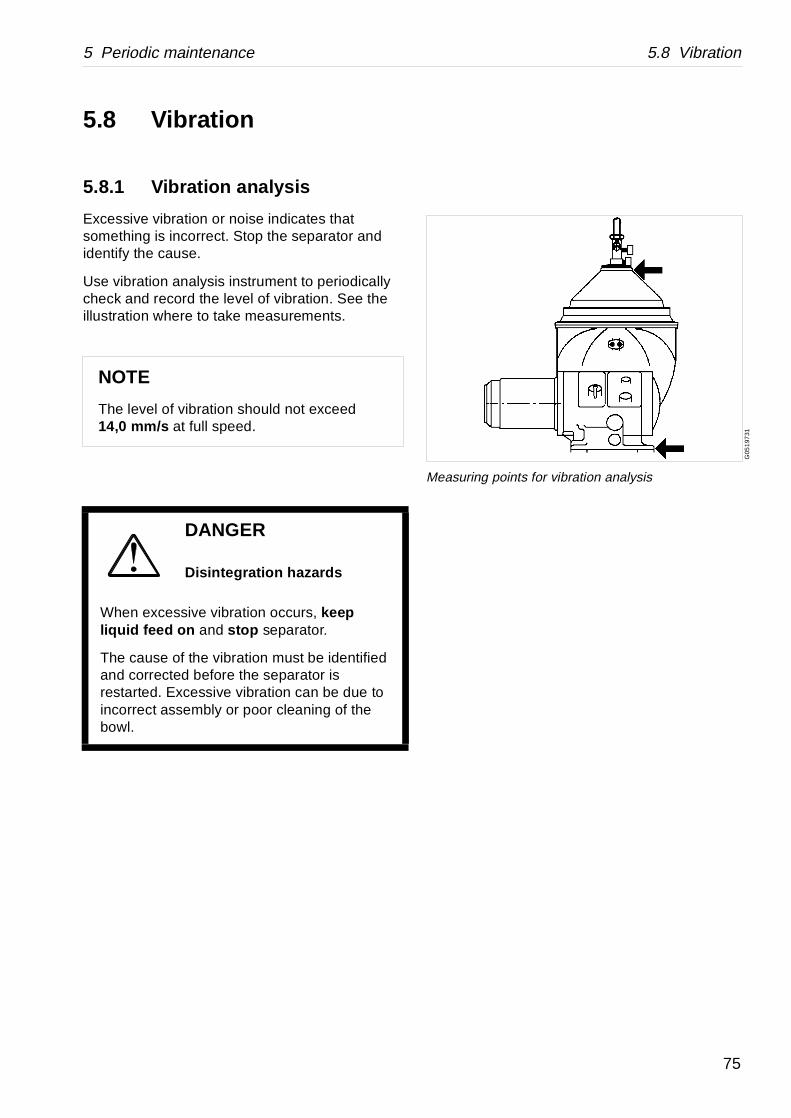
Measuring points for vibration analysis
5.8 Vibration
5.8.1 Vibration analysis
Excessive vibration or noise indicates that something is incorrect. Stop the separator and identify the cause.
Use vibration analysis instrument to periodically check and record the level of vibration. See the illustration where to take measurements.
NOTE
The level of vibration should not exceed 14,0 mm/s at full speed.
DANGER
Disintegration hazards
When excessive vibration occurs, keep liquid feed on and stop separator.
The cause of the vibration must be identified and corrected before the separator is restarted. Excessive vibration can be due to incorrect assembly or poor cleaning of the bowl.
75

5.9 Common maintenance directions 5 Periodic maintenance
G0
587
321
1. Outer race2. Ball/roller3. Inner race4. Cage
5.9 Common maintenance directions
5.9.1 Balancing of bowl
The separator bowl is statically and dynamically factory-balanced only as a complete unit .
Major bowl parts cannot be replaced with new parts without rebalancing the entire bowl.
Bowl parts must never be interchanged from one machine to an other.
5.9.2 Ball and roller bearings
Special-design bearings for the bowl spindle
The bearings used for the bowl spindle are special to withstand the speed, vibration, temperature and load characteristics of high-speed separators.
Only Alfa Laval genuine spare parts should be used.
A bearing that in appearance looks equivalent to the correct may be considerably different in various respects: inside clearances, design and tolerances of the cage and races as well as material and heat treatment.
NOTE
Using an incorrect bearing can cause a serious breakdown with damage to equipment as a result.
Do not re-fit a used bearing. Always replace it with a new.
76

5 Periodic maintenance 5.9 Common maintenance directions
G05
874
11
For bearings where no driving-off sleeve is included in the tool kit, use a puller when removing bearings
G0
5875
11
Clean and oil the bearing seating before assembly
Dismantling
For bearings where no driving-off sleeve is included in the tool kit, remove the bearing from its seat by using a puller. If possible, let the puller engage the inner ring, then remove the bearing with a steady force until the bearing bore completely clears the entire length of the cylindrical seat.
The puller should be accurately centered during dismantling; otherwise, it is easy to damage the seating.
Cleaning and inspection
Check shaft (spindle) end and/or bearing seat in the housing for damage indicating that the bearing has rotated on the shaft (spindle) and/or in the housing respectively. Replace the damaged part(s), if the faults cannot be remedied by polishing.
Assembly
• Leave new bearings in original wrapping until ready to fit. The anti-rust agent protecting a new bearing should not be removed before use.
• Use the greatest cleanliness when handling the bearings.
• To facilitate assembly and also reduce the risk of damage, first clean and then lightly oil the bearing seating on shaft (spindle) or alternatively in housing, with a thin oil.
NOTE
Do not hit with a hammer directly on the bearing.
77
5.9 Common maintenance directions 5 Periodic maintenance
G05
8761
1
The bearing must not be in direct contact with the container
G0
5877
11
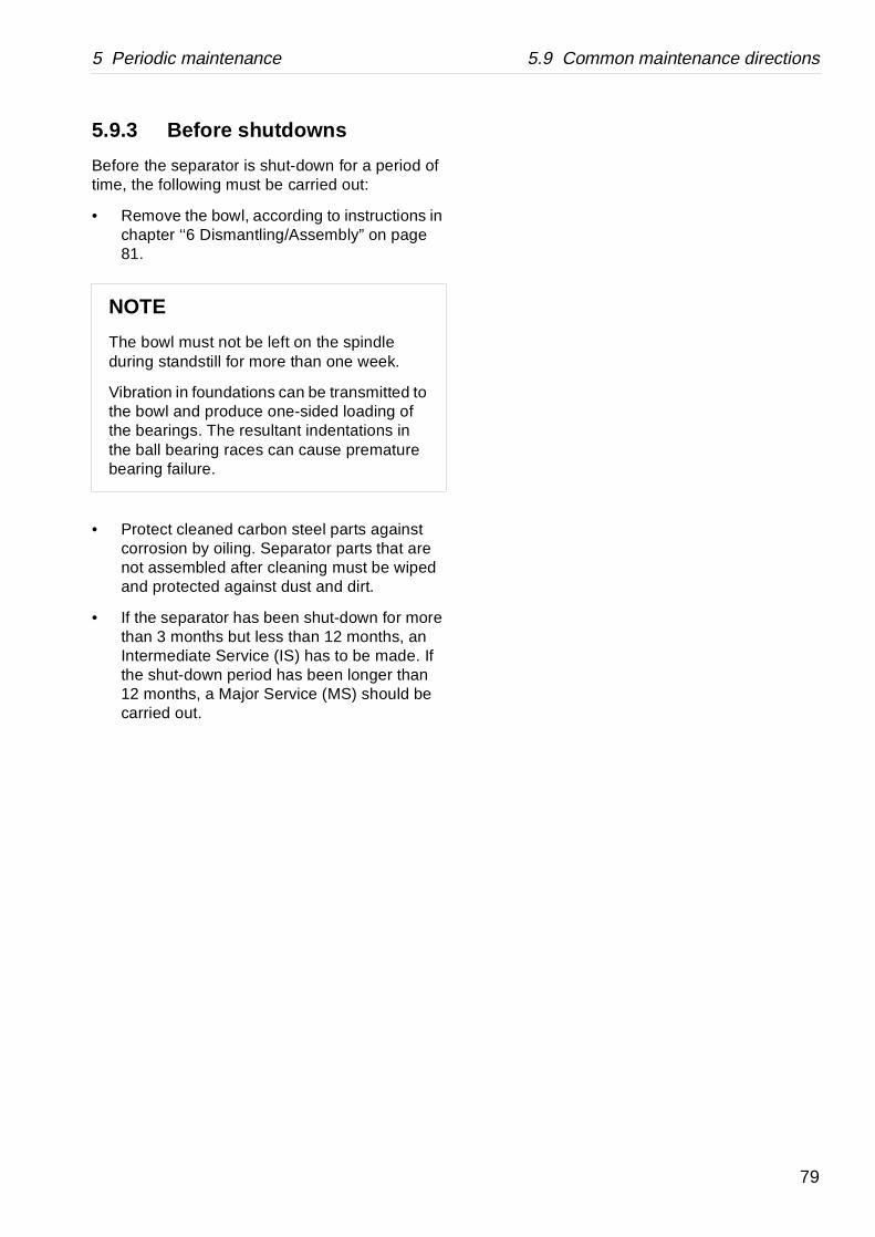
Use a driving-on sleeve for bearings that are not heated
G0
5872
11
The wide shoulder of the inner race must face the axial load
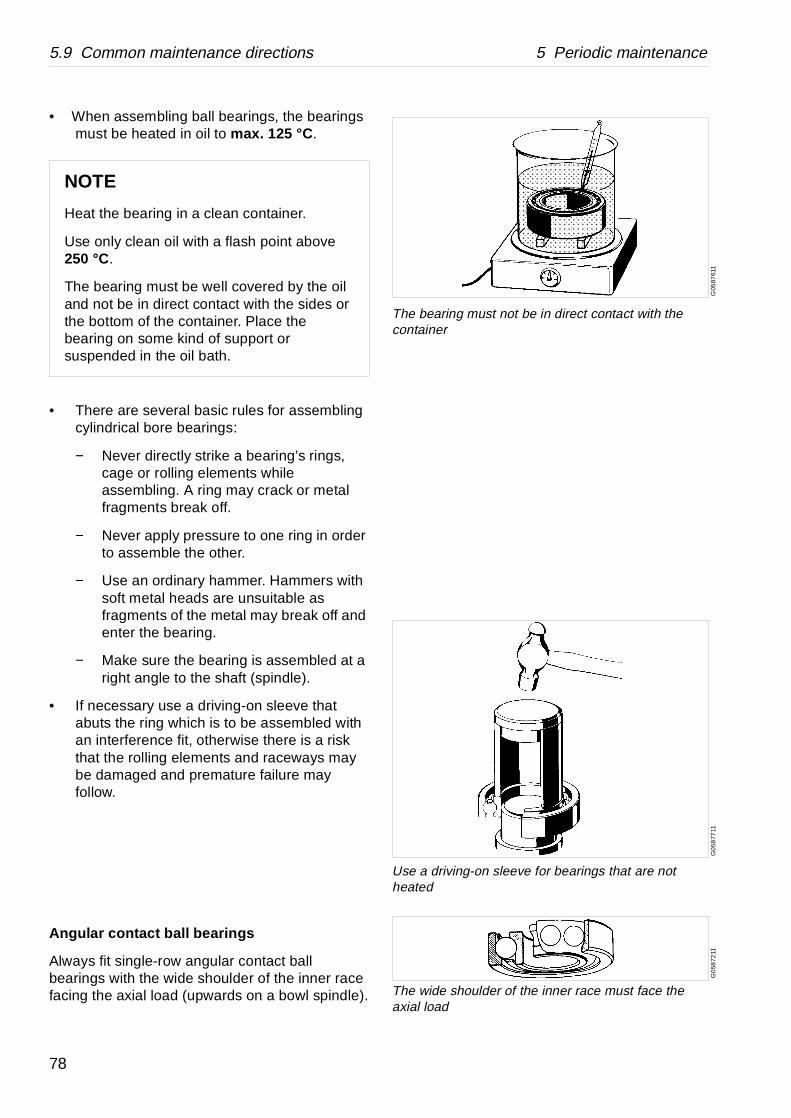
• When assembling ball bearings, the bearings must be heated in oil to max. 125 °C .
• There are several basic rules for assembling cylindrical bore bearings:
− Never directly strike a bearing’s rings, cage or rolling elements while assembling. A ring may crack or metal fragments break off.
− Never apply pressure to one ring in order to assemble the other.
− Use an ordinary hammer. Hammers with soft metal heads are unsuitable as fragments of the metal may break off and enter the bearing.
− Make sure the bearing is assembled at a right angle to the shaft (spindle).
• If necessary use a driving-on sleeve that abuts the ring which is to be assembled with an interference fit, otherwise there is a risk that the rolling elements and raceways may be damaged and premature failure may follow.
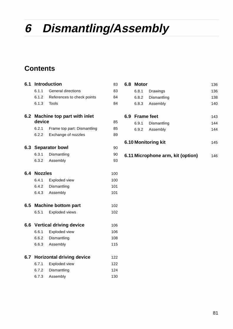
Angular contact ball bearings
Always fit single-row angular contact ball bearings with the wide shoulder of the inner race facing the axial load (upwards on a bowl spindle).
NOTE
Heat the bearing in a clean container.
Use only clean oil with a flash point above 250 °C.
The bearing must be well covered by the oil and not be in direct contact with the sides or the bottom of the container. Place the bearing on some kind of support or suspended in the oil bath.
78
5 Periodic maintenance 5.9 Common maintenance directions
5.9.3 Before shutdowns
Before the separator is shut-down for a period of time, the following must be carried out:
• Remove the bowl, according to instructions in chapter ‘‘6 Dismantling/Assembly” on page 81.
• Protect cleaned carbon steel parts against corrosion by oiling. Separator parts that are not assembled after cleaning must be wiped and protected against dust and dirt.
• If the separator has been shut-down for more than 3 months but less than 12 months, an Intermediate Service (IS) has to be made. If the shut-down period has been longer than 12 months, a Major Service (MS) should be carried out.
NOTE
The bowl must not be left on the spindle during standstill for more than one week.
Vibration in foundations can be transmitted to the bowl and produce one-sided loading of the bearings. The resultant indentations in the ball bearing races can cause premature bearing failure.
79

5.9 Common maintenance directions 5 Periodic maintenance
80
6 Dismantling/Assembly
Contents
6.1 Introduction 83
6.1.1 General directions 83
6.1.2 References to check points 84
6.1.3 Tools 84
6.2 Machine top part with inlet device 85
6.2.1 Frame top part: Dismantling 85
6.2.2 Exchange of nozzles 89
6.3 Separator bowl 90
6.3.1 Dismantling 90
6.3.2 Assembly 93
6.4 Nozzles 100
6.4.1 Exploded view 100
6.4.2 Dismantling 101
6.4.3 Assembly 101
6.5 Machine bottom part 102
6.5.1 Exploded views 102
6.6 Vertical driving device 106
6.6.1 Exploded view 106
6.6.2 Dismantling 108
6.6.3 Assembly 115
6.7 Horizontal driving device 122
6.7.1 Exploded view 122
6.7.2 Dismantling 124
6.7.3 Assembly 130
6.8 Motor 136
6.8.1 Drawings 136
6.8.2 Dismantling 138
6.8.3 Assembly 140
6.9 Frame feet 143
6.9.1 Dismantling 144
6.9.2 Assembly 144
6.10 Monitoring kit 145
6.11 Microphone arm, kit (option) 146
81

82

6 Dismantling/Assembly 6.1 Introduction
G02
462
21
The revolution counter indicates if the separator still is rotating
6.1 Introduction
6.1.1 General directions
The separator must be dismantled regularly for cleaning and inspection.
The recommended intervals are stated in chapter ‘‘5.1.1 Maintenance intervals” on page 37.
The collecting cover and heavy bowl parts must be lifted by hoist. Position the hoist directly above the bowl centre. Use an endless sling and a lifting hook with catch.
These parts must be handled carefully.
Do not place parts directly on the floor, but on a clean rubber mat, fibreboard or a suitable pallet.
DANGER
Entrapment hazard
Make sure that rotating parts have come to a complete standstill before starting any dismantling work.
The revolution counter and the motor fan indicate if separator parts are rotating or not.
NOTE
Never interchange bowl parts
To prevent mixing of parts, e.g. in an installation comprising several machines of the same type, the major bowl parts carry the machine manufacturing number or its last three digits.
83
6.1 Introduction 6 Dismantling/Assembly
6.1.2 References to check points
In the text you will find references to the Check point instructions in chapter 5. The references appear in the text as in the following example:
Check point‘‘5.3.8 Disc stack pressure” on page 58.
In this example, look up check point Disc stack pressure in chapter 5 for further instructions.
6.1.3 Tools
Special tools from the tool kit must be used for dismantling and assembly. The special tools are specified in the Spare Parts Catalogue.
NOTE
When lifting parts without weight specifications, always use lifting straps with the capacity of at least 500 kg .
84

6 Dismantling/Assembly 6.2 Machine top part with inlet device
G0
5663
41G
056
644
1
6.2 Machine top part with inlet device
6.2.1 Frame top part: Dismantling
1. Disconnect the feed inlet (A) and the outlet pipe (B).
Use hook spanner.
2. Disconnect the inlet housing using the hook spanner.
Remove the inlet housing.
DANGER
Entrapment hazard
Make sure that rotating parts have come to a complete standstill before starting any dismantling work.
The revolution counter and the motor fan indicates if separator parts are rotating or not.
85

6.2 Machine top part with inlet device 6 Dismantling/Assembly
G0
577
441
G0
566
531
G0
7831
41G
031
172
1
3. Unscrew and remove the nut holding the vertical inlet pipe using the hook spanner. Note! Left hand thread!
4. Remove the cap nuts holding the outlet housing.
Use the 24 mm socket and ratchet spanner for the nuts.
Remove the outlet housing.
5. Loosen the nuts under the twelve hook screws in the frame hood and turn the hooks.
6. Fasten the two lifting eyes onto the frame hood.
Fit a lifting strap with snap hooks.
86
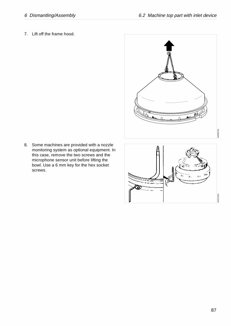
6 Dismantling/Assembly 6.2 Machine top part with inlet device
G0
560
791
G0
3120
41
7. Lift off the frame hood.
8. Some machines are provided with a nozzle monitoring system as optional equipment. In this case, remove the two screws and the microphone sensor unit before lifting the bowl. Use a 6 mm key for the hex socket screws.
87

88
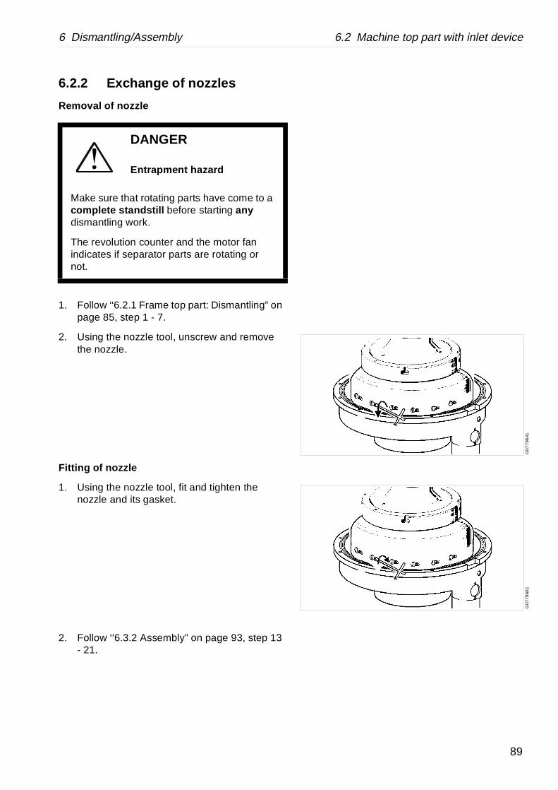
6 Dismantling/Assembly 6.2 Machine top part with inlet device
G07
796
41G
0779
661
6.2.2 Exchange of nozzles
Removal of nozzle
1. Follow ‘‘6.2.1 Frame top part: Dismantling” on page 85, step 1 - 7.
2. Using the nozzle tool, unscrew and remove the nozzle.
Fitting of nozzle
1. Using the nozzle tool, fit and tighten the nozzle and its gasket.
2. Follow ‘‘6.3.2 Assembly” on page 93, step 13 - 21.
DANGER
Entrapment hazard
Make sure that rotating parts have come to a complete standstill before starting any dismantling work.
The revolution counter and the motor fan indicates if separator parts are rotating or not.
89
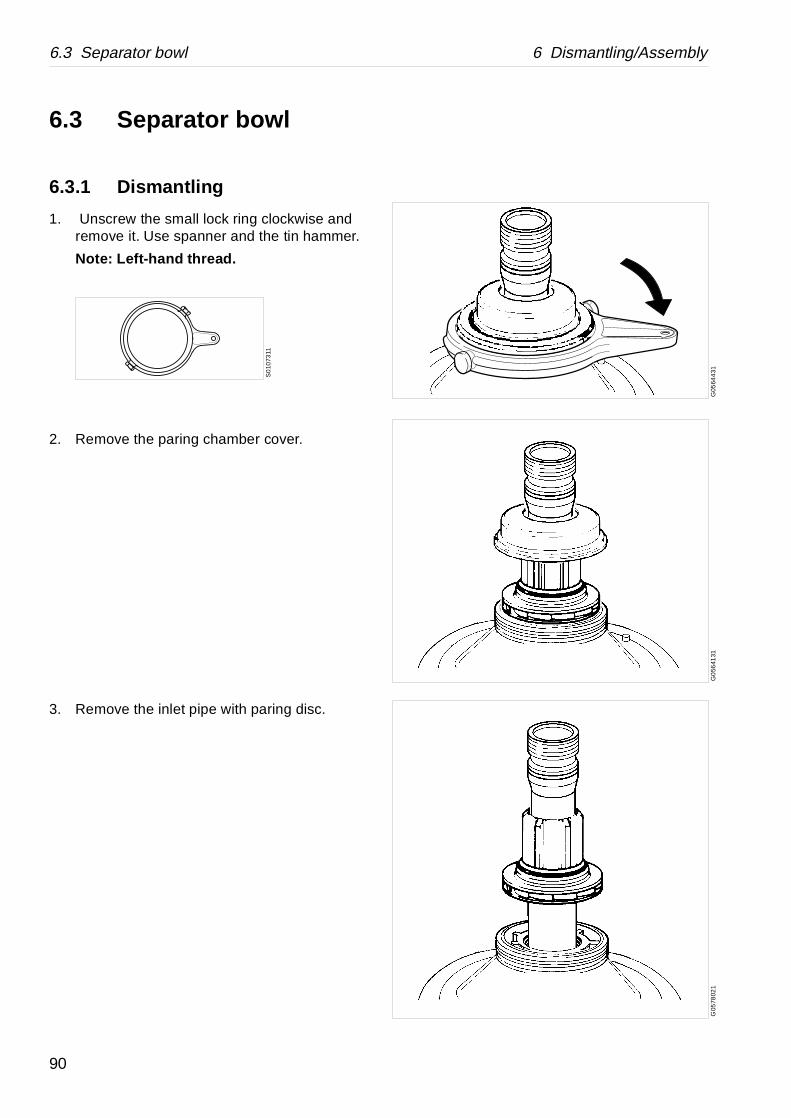
6.3 Separator bowl 6 Dismantling/Assembly
G05
644
31G
056
4131
G05
7802
1
6.3 Separator bowl
6.3.1 Dismantling
1. Unscrew the small lock ring clockwise and remove it. Use spanner and the tin hammer.
Note: Left-hand thread.
2. Remove the paring chamber cover.
3. Remove the inlet pipe with paring disc.
S0
1073
11
90

6 Dismantling/Assembly 6.3 Separator bowl
G0
773
461
G03
135
41G
079
0411
4. Unscrew the large lock ring with the lock ring spanner.
Note: Left-hand thread!
Remove the large lock ring.
5. Remove the bowl hood. Use the lifting tool for the bowl hood, lifting sling and hoist.
6. Fit the special lifting tool to distributor and lift it of together with the disc stack.
NOTE
The large lock ring must be placed resting on a flat horizontal surface to avoid distortion.
Only slight distortion can make it impossible to refit.
CAUTION
Cut hazard
Sharp edges on separator discs may cause cuts.
S01
074
11
91

6.3 Separator bowl 6 Dismantling/Assembly
G0
7902
21G
079
0311
G03
142
41
7. Loosen and remove the cap nut.
Left-hand thread!
8. Fit the special tool to bowl body. Loosen the bowl body from the tapered end by screwing down the lifting eye nut.
9. Lift out the bowl.
Bowl with fillerpieces.
10. Clean out product from bore, loosen the screw and lift out the filler piece. The gasket under the screwhead is to be renewed.
NOTE
Do not forget to loosen the bowl body from the tapered end of the bowl spindle by means of the central screw.
WARNING
Crush hazard
Support the bowl body when turning to prevent it from rolling.
92
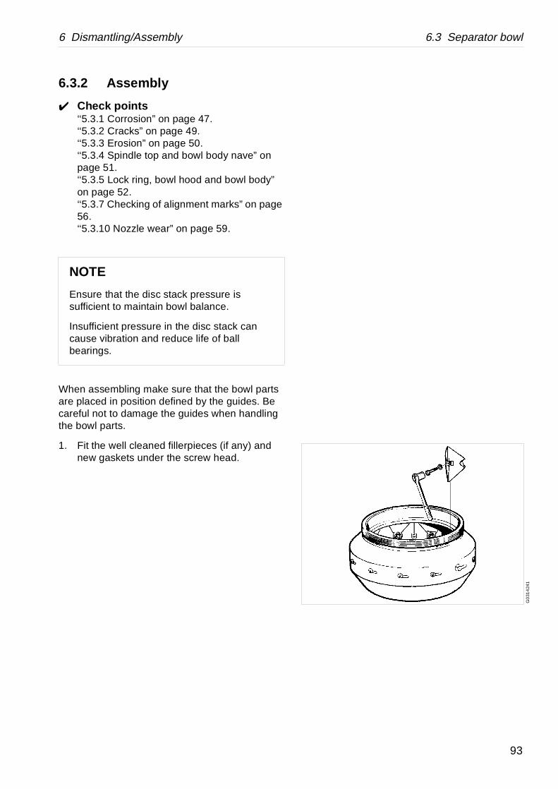
6 Dismantling/Assembly 6.3 Separator bowl
G0
314
241
6.3.2 Assembly
Check points‘‘5.3.1 Corrosion” on page 47.‘‘5.3.2 Cracks” on page 49.‘‘5.3.3 Erosion” on page 50.‘‘5.3.4 Spindle top and bowl body nave” on page 51.‘‘5.3.5 Lock ring, bowl hood and bowl body” on page 52.‘‘5.3.7 Checking of alignment marks” on page 56.‘‘5.3.10 Nozzle wear” on page 59.
When assembling make sure that the bowl parts are placed in position defined by the guides. Be careful not to damage the guides when handling the bowl parts.
1. Fit the well cleaned fillerpieces (if any) and new gaskets under the screw head.
NOTE
Ensure that the disc stack pressure is sufficient to maintain bowl balance.
Insufficient pressure in the disc stack can cause vibration and reduce life of ball bearings.
93
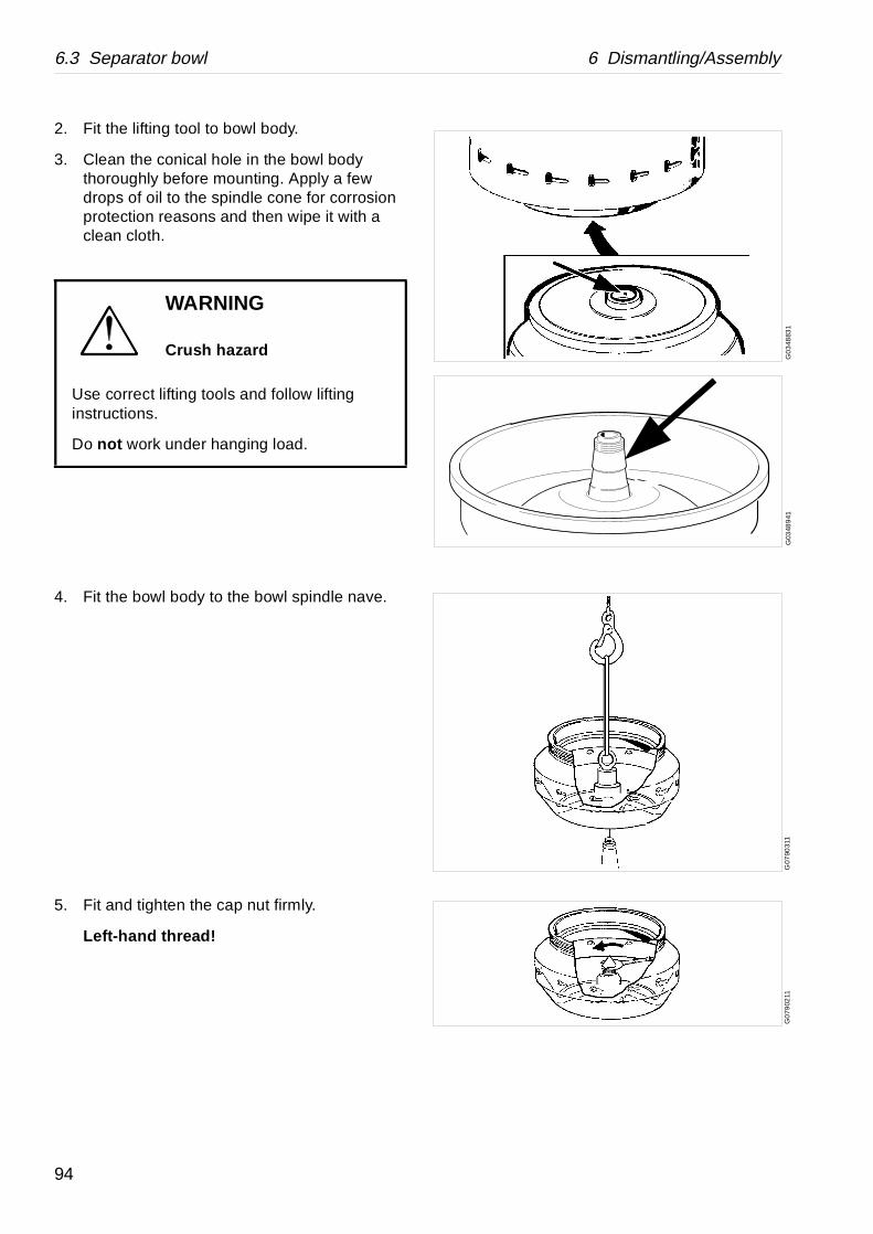
6.3 Separator bowl 6 Dismantling/Assembly
G0
348
831
G03
489
41G
0790
311
G0
7902
11
2. Fit the lifting tool to bowl body.
3. Clean the conical hole in the bowl body thoroughly before mounting. Apply a few drops of oil to the spindle cone for corrosion protection reasons and then wipe it with a clean cloth.
4. Fit the bowl body to the bowl spindle nave.
5. Fit and tighten the cap nut firmly.
Left-hand thread!
WARNING
Crush hazard
Use correct lifting tools and follow lifting instructions.
Do not work under hanging load.
94
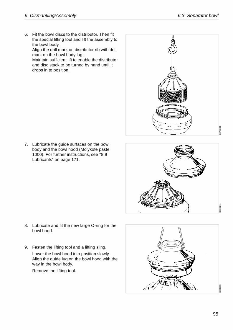
6 Dismantling/Assembly 6.3 Separator bowl
G0
790
411
G0
3482
61
G0
3135
51
6. Fit the bowl discs to the distributor. Then fit the special lifting tool and lift the assembly to the bowl body.Align the drill mark on distributor rib with drill mark on the bowl body lug.Maintain sufficient lift to enable the distributor and disc stack to be turned by hand until it drops in to position.
7. Lubricate the guide surfaces on the bowl body and the bowl hood (Molykote paste 1000). For further instructions, see ‘‘8.9 Lubricants” on page 171.
8. Lubricate and fit the new large O-ring for the bowl hood.
9. Fasten the lifting tool and a lifting sling.
Lower the bowl hood into position slowly. Align the guide lug on the bowl hood with the way in the bowl body.
Remove the lifting tool.
95
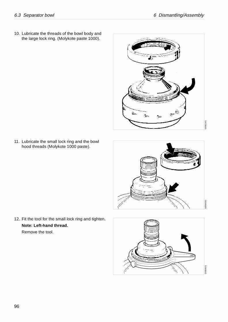
6.3 Separator bowl 6 Dismantling/Assembly
G0
561
341
G05
6433
1G
056
442
1
10. Lubricate the threads of the bowl body and the large lock ring. (Molykote paste 1000).
11. Lubricate the small lock ring and the bowl hood threads (Molykote 1000 paste).
12. Fit the tool for the small lock ring and tighten.
Note: Left-hand thread.
Remove the tool.
96
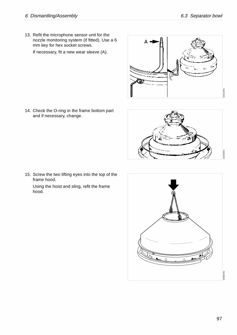
6 Dismantling/Assembly 6.3 Separator bowl
G03
120
51G
031
9341
G0
560
781
13. Refit the microphone sensor unit for the nozzle monitoring system (if fitted). Use a 6 mm key for hex socket screws.
If necessary, fit a new wear sleeve (A).
14. Check the O-ring in the frame bottom part and if necessary, change.
15. Screw the two lifting eyes into the top of the frame hood.
Using the hoist and sling, refit the frame hood.
97

6.3 Separator bowl 6 Dismantling/Assembly
G07
831
31G
0319
621
G03
1971
1G
056
653
1
16. Fasten the twelve hook screws in the frame hood.
17. Remove the two lifting eyes.
18. Refit the height adjustment gaskets (1-5), if they have been removed.
19. Lubricate and fit the new O-ring for the outlet housing.
Fit the outlet housing and tighten the six cap nuts. Use the 24 mm socket and ratchet spanner.
NOTE
Measure (and adjust if necessary) the height of the frame hood relative to the top of the wings in the paring chamber. See ‘‘5.4.10 Height adjustment: Inlet and outlet device” on page 64.
98
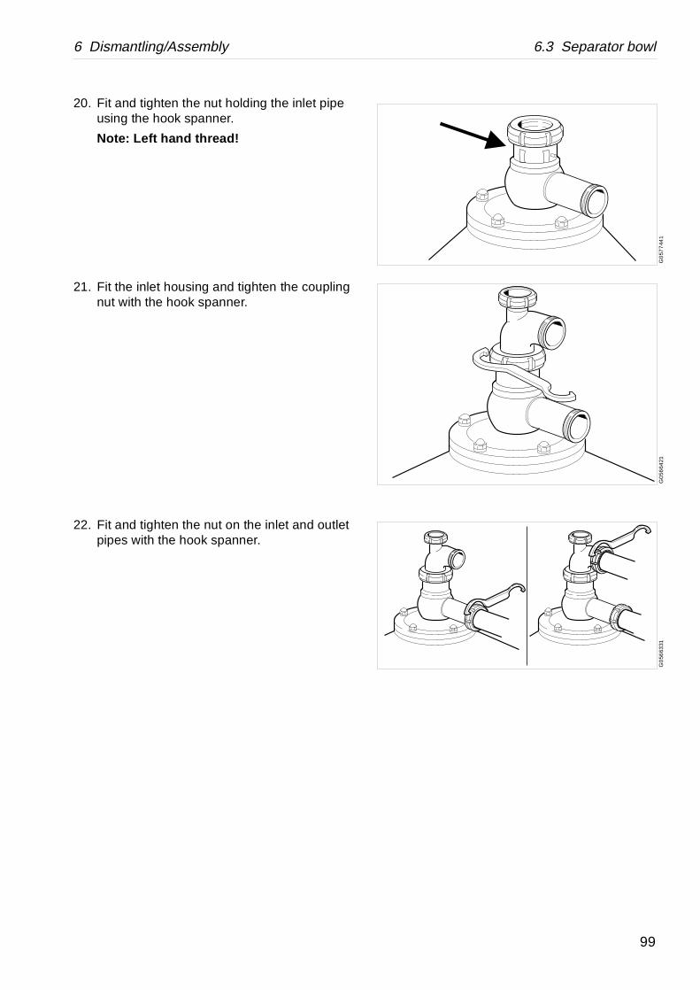
6 Dismantling/Assembly 6.3 Separator bowl
G0
577
441
G0
5664
21G
056
6331
20. Fit and tighten the nut holding the inlet pipe using the hook spanner.
Note: Left hand thread!
21. Fit the inlet housing and tighten the coupling nut with the hook spanner.
22. Fit and tighten the nut on the inlet and outlet pipes with the hook spanner.
99
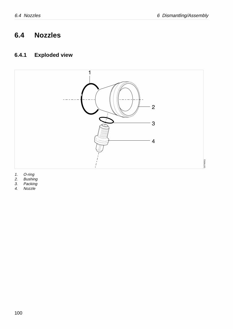
6.4 Nozzles 6 Dismantling/Assembly
G07
908
11
6.4 Nozzles
6.4.1 Exploded view
1. O-ring2. Bushing3. Packing4. Nozzle
100

6 Dismantling/Assembly 6.4 Nozzles
G07
8991
1G
0790
011
6.4.2 Dismantling
1. Unscrew the nozzle.
2. Force out the bushing into the bowl body interior.
6.4.3 Assembly
1. Clean the bushing seat.
2. Put the seal ring in the groove of the new bushing and push the latter into the bushing seat.
3. Screw home the mounting tool and push in the tool sleeve in the bushing as far as possible.
4. Place the mounting tool in the bowl body between the new bushing and the diametrically opposite one. Turn the hexagon screw of the tool until the bushing has entered its seat.
5. Secure the bushing by upsetting its upper and lower edges over the bowl body.
6. Screw in the nozzle with packing applied.
101
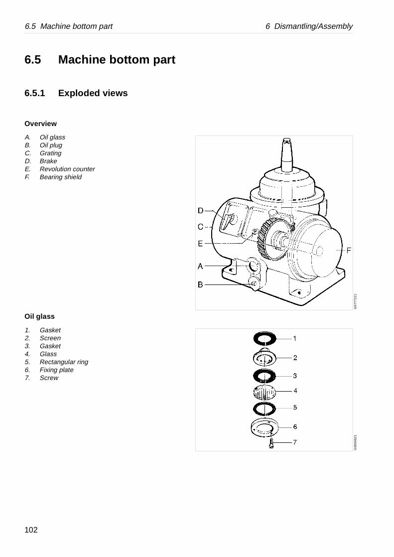
6.5 Machine bottom part 6 Dismantling/Assembly
G0
7772
21
G06
5462
1
6.5 Machine bottom part
6.5.1 Exploded views
Overview
A. Oil glassB. Oil plugC. GratingD. BrakeE. Revolution counterF. Bearing shield
Oil glass
1. Gasket2. Screen3. Gasket4. Glass5. Rectangular ring6. Fixing plate7. Screw
102
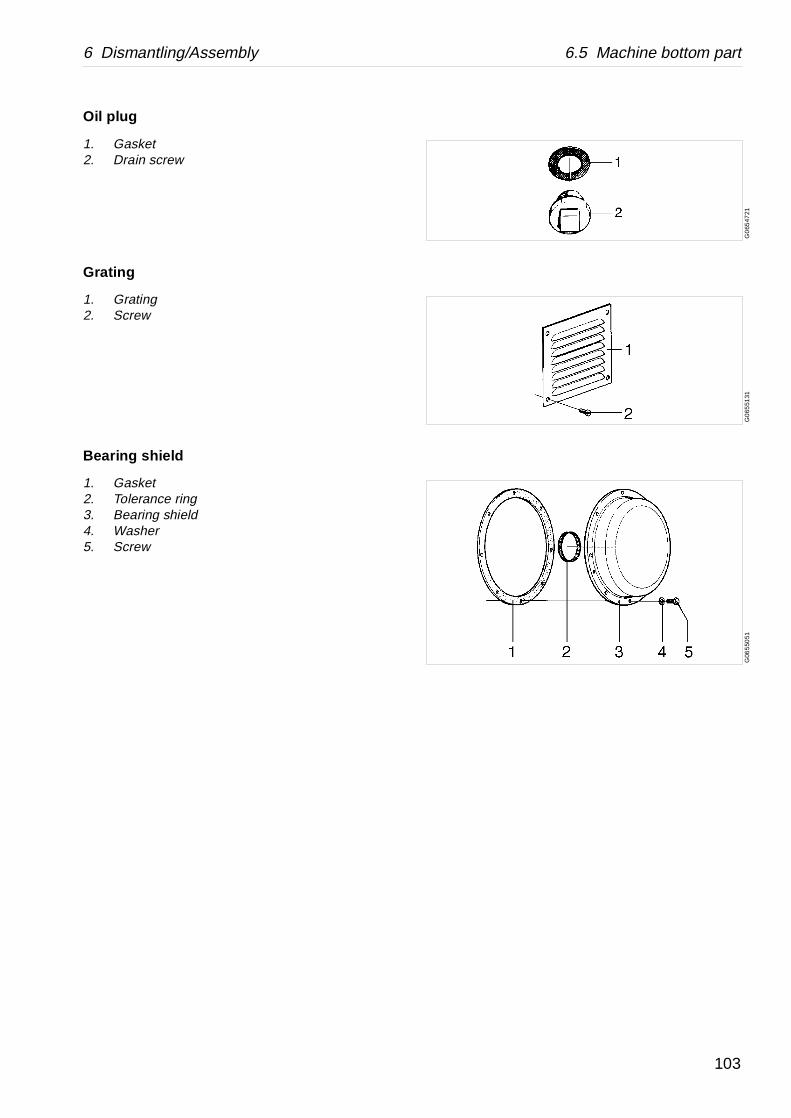
6 Dismantling/Assembly 6.5 Machine bottom part
G0
6547
21G
065
5131
G06
550
51
Oil plug
1. Gasket2. Drain screw
Grating
1. Grating2. Screw
Bearing shield
1. Gasket2. Tolerance ring3. Bearing shield4. Washer5. Screw
103
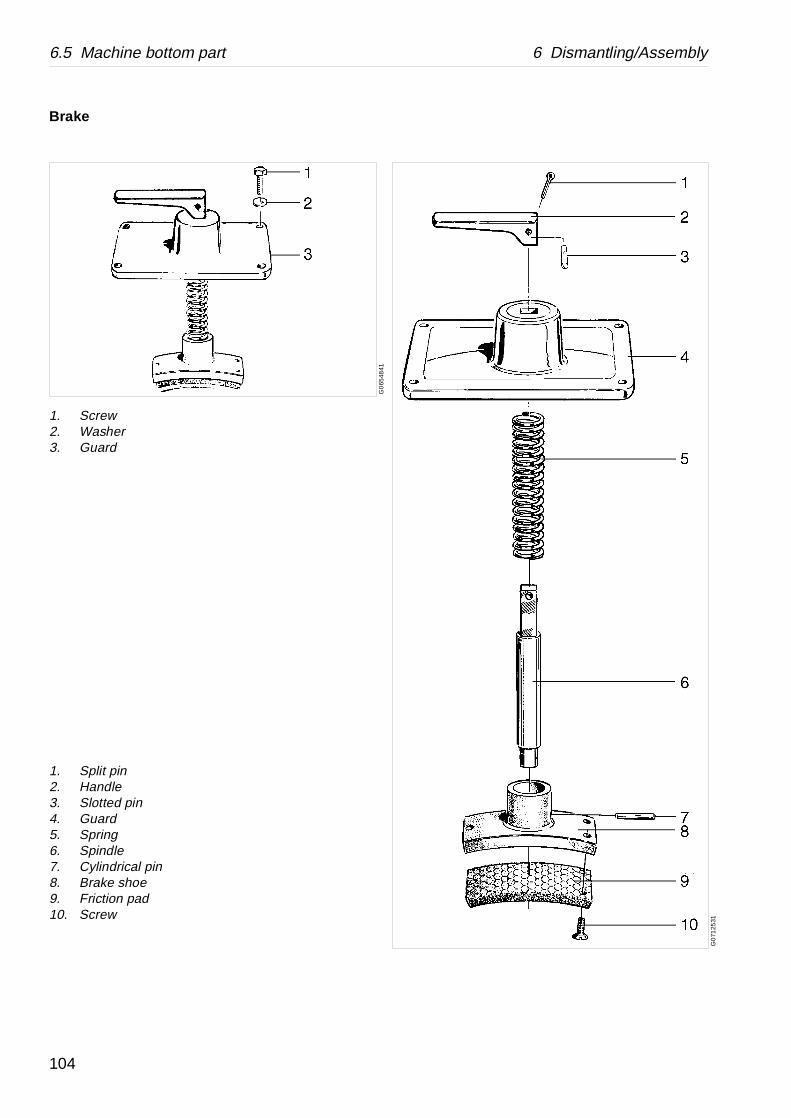
6.5 Machine bottom part 6 Dismantling/Assembly
G0
7125
31
G0
6548
41
Brake
1. Screw2. Washer3. Guard
1. Split pin2. Handle3. Slotted pin4. Guard5. Spring6. Spindle7. Cylindrical pin8. Brake shoe9. Friction pad10. Screw
104
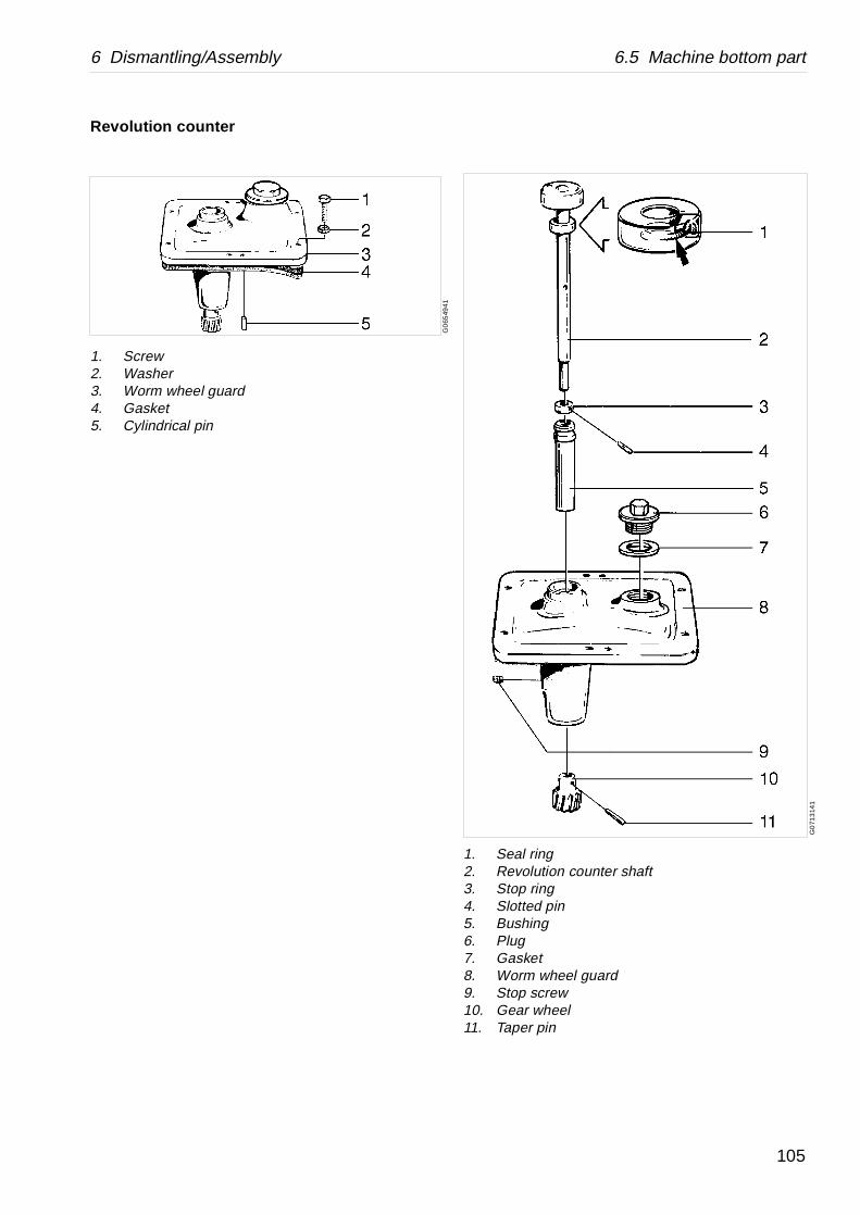
6 Dismantling/Assembly 6.5 Machine bottom part
G0
713
141
1. Seal ring2. Revolution counter shaft3. Stop ring4. Slotted pin5. Bushing6. Plug7. Gasket8. Worm wheel guard9. Stop screw10. Gear wheel11. Taper pin
Revolution c ounter
1. Screw2. Washer3. Worm wheel guard4. Gasket5. Cylindrical pin
G0
6549
41
105

6.6 Vertical driving device 6 Dismantling/Assembly
G0
788
611
6.6 Vertical driving device
6.6.1 Exploded view
106

6 Dismantling/Assembly 6.6 Vertical driving device
1. Screw2. Protecting plate3. O-ring4. Protecting collar5. Screw6. Guard7. Nut8. Cover for spring housing9. Gasket10. Oil fan11. O-ring12. Stud bolt13. Buffer14. Spring15. Screw plug16. Bowl spindle17. Lock ring18. Ball bearing19. Spring support20. Spring21. Spring support22. Spacing sleeve23. Ball bearing24. Ball bearing housing25. Buffer26. Split pin27. Wear ring28. Spring29. Spring support30. Spring casing31. Gasket32. Round nut33. Lock washer34. Ball bearing35. Spring36. Spacing sleeve37. Ball bearing38. Worm39. Conveyor40. Ball bearing41. Washer42. Lock washer43. Round nut44. O-ring45. Bottom bearing housing46. Screw
107

6.6 Vertical driving device 6 Dismantling/Assembly
G0
2462
21
S0
0510
11G
0484
211
G0
127
911
6.6.2 Dismantling
1. Drain off the oil from the gear housing.
2. Remove the cover before starting any dismantling. Check the teeth of the worm wheel and worm for wear. See ‘‘5.7.1 Worm wheel and worm; wear of teeth” on page 71.
DANGER
Entrapment hazards
1. Make sure that rotating parts have come to a complete standstill before starting any dismantling work.
The revolution counter and the motor fan indicates if separator parts are rotating or not.
2. To avoid accidental start, switch off and lock power supply before starting any dismantling work.
CAUTION
Burn hazards
Lubricating oil and various machine surfaces can be hot and cause burns.
108
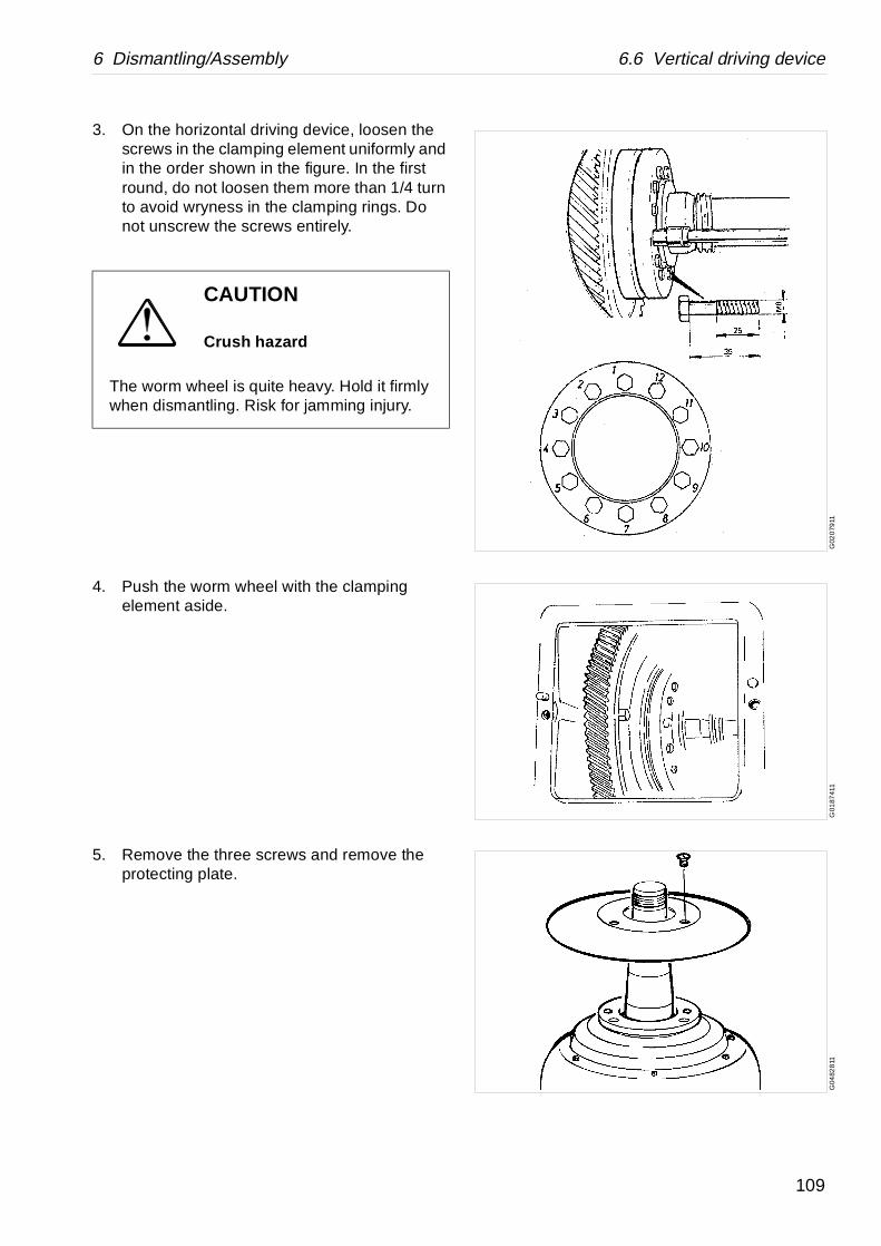
6 Dismantling/Assembly 6.6 Vertical driving device
G02
079
11G
0187
411
G04
828
11
3. On the horizontal driving device, loosen the screws in the clamping element uniformly and in the order shown in the figure. In the first round, do not loosen them more than 1/4 turn to avoid wryness in the clamping rings. Do not unscrew the screws entirely.
4. Push the worm wheel with the clamping element aside.
5. Remove the three screws and remove the protecting plate.
CAUTION
Crush hazard
The worm wheel is quite heavy. Hold it firmly when dismantling. Risk for jamming injury.
109

6.6 Vertical driving device 6 Dismantling/Assembly
G0
4829
11G
048
301
1G
0483
111
6. Remove the O-ring. Remove the throw-off collar with the special tool.
7. Unscrew the six screws. Remove the protecting hood and the O-ring.
8. Loosen the screw plugs half-a-turn using the spanner and a hammer.
110

6 Dismantling/Assembly 6.6 Vertical driving device
G0
483
211
G04
9931
1G
049
941
1
9. Unscrew the six nuts and remove the spring housing cover and packing.
Note! The nuts are locked with Loctite.
10. Unscrew the oil fan clockwise.
Left-hand thread!
11. Loosen the lock ring half-a-turn counter-clock-wise.
111

6.6 Vertical driving device 6 Dismantling/Assembly
G04
8331
1G
048
3411
G04
8351
1G
0499
011
12. Fit the lifting eye bolt. Lift out the spindle unit carefully and place it horizontally.
13. Use some pieces of wood for support.
14. Remove the packing.
15. Make a wooden support to be used during certain sub-operations.
Open the lock washer and loosen the nut using the hook key.
112
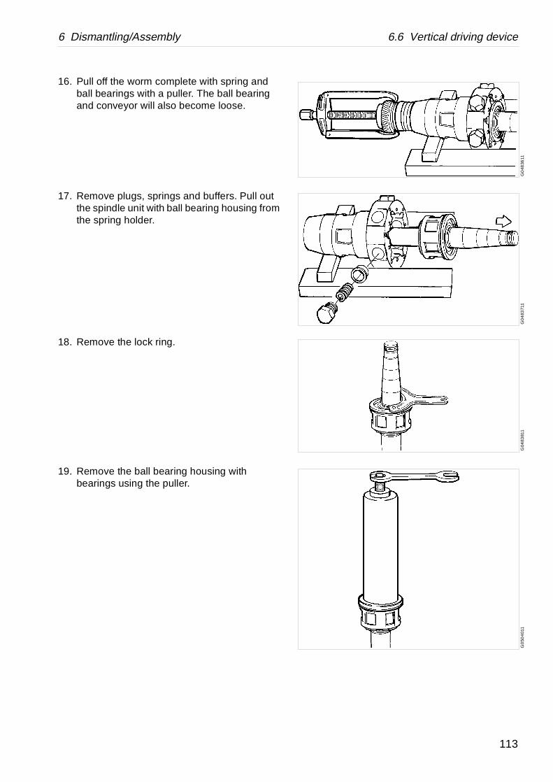
6 Dismantling/Assembly 6.6 Vertical driving device
G0
4836
11G
04
8371
1G
0483
811
G0
504
011
16. Pull off the worm complete with spring and ball bearings with a puller. The ball bearing and conveyor will also become loose.
17. Remove plugs, springs and buffers. Pull out the spindle unit with ball bearing housing from the spring holder.
18. Remove the lock ring.
19. Remove the ball bearing housing with bearings using the puller.
113

6.6 Vertical driving device 6 Dismantling/Assembly
G0
483
911
G04
8641
1G
0484
121
20. Push out ball bearing, sprint support, springs, spring support, spacing sleeve and ball bearing.
21. Remove the axial buffer.
22. Open the lock washer and loosen the nut. Knock loose the bearing from the worm using the special tool.
Remove round nut, lock washer, ball bearing, spring, spacing sleeve and ball bearing.
114

6 Dismantling/Assembly 6.6 Vertical driving device
G0
189
011
6.6.3 Assembly
Check points‘‘5.3.1 Corrosion” on page 47.‘‘5.3.2 Cracks” on page 49.‘‘5.3.3 Erosion” on page 50.‘‘5.7.1 Worm wheel and worm; wear of teeth” on page 71.‘‘5.3.4 Spindle top and bowl body nave” on page 51.
1. Wipe off and oil the bearing seat before fitting the ball bearing.
NOTE
The bearings used for the bowl spindle are specifically designed to withstand the speed, vibration, temperature and load characteristics of high-speed separators.
Do not use other bearings than those stated in Spare Parts Catalogue.
Use of other bearings can cause serious breakdown which could result in injury or damage to health and equipment.
Do not refit a used bearing. Always replace it with a new one.
115

6.6 Vertical driving device 6 Dismantling/Assembly
G04
8611
1G
048
6011
G0
486
311
2. Fit the ball bearing, spacing sleeve, spring support , springs, spring support and ball bearing in the ball bearing housing.
Note! The deep groove ball bearing (A) is to be mounted in the upper housing and the angular ball bearing (B) in the lower one.
Note! Turn the angular ball bearing (B) the right way - IMPORTANT! The wider shoulder of the inner race must face upwards.
3. Heat the complete unit to 125 °C.
4. Fit the unit on the spindle while still hot. Lock with the oil fan.
Left-hand thread!
NOTE
If any doubt how to mount roller bearings in a correct way, see the detailed description in chapter ‘‘5.9.2 Ball and roller bearings” on page 76.
116

6 Dismantling/Assembly 6.6 Vertical driving device
G04
864
11G
048
6511
5. Fit the axial buffer in the spring housing.
It is recommended to support the spring housing so the spindle is free below.
6. Place the spindle unit in the spring housing.
117

6.6 Vertical driving device 6 Dismantling/Assembly
G04
8661
1G
04
8673
1
7. Fit buffers, springs and screw plugs.
8. Heat ball bearings (3) and (6) to 125 °C.
Fit the ball bearing (6), spacing sleeve (5), spring (4), ball bearing (3), lock washer (2), and round nut (1) onto worm and lock with washer.
118

6 Dismantling/Assembly 6.6 Vertical driving device
G0
486
811
G0
486
911
G04
870
31G
0487
111
G0
508
111
9. Fit the worm with spring component to the spring housing.
10. Fit the conveyor with the drill marks facing the threads of the spindle.
11. Heat the ball bearing to 125 °C and fit it to the spindle.
12. Fit the intermediate washer, the lock washer, the round nut and lock the washer.
13. Fit a new packing and O-ring. If the stud bolts have been removed, refit them and lock with Loctite 270.
119

6.6 Vertical driving device 6 Dismantling/Assembly
G0
4873
11G
048
3211
G0
4831
11
14. Fit the lifting eye on the spindle top. Carefully lower the spindle into the frame.
Guide the bottom bearing into the bottom sleeve. If it does not completely enter its seat, tap the spindle top gently with a tin hammer.
15. Fit the packing and spring housing cover. Secure the spindle unit in the frame with the nuts. Lock them with Loctite 242.
16. Knock down the spindle with a few taps on the spindle top with a tin hammer. Tighten the screw plugs.
Rotate the spindle a few turns to make sure that there is no obstruction.
120
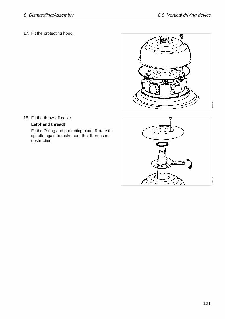
6 Dismantling/Assembly 6.6 Vertical driving device
G04
8301
1G
048
7711
17. Fit the protecting hood.
18. Fit the throw-off collar.
Left-hand thread!
Fit the O-ring and protecting plate. Rotate the spindle again to make sure that there is no obstruction.
121

6.7 Horizontal driving device 6 Dismantling/Assembly
G07
787
11
6.7 Horizontal driving device
6.7.1 Exploded view
122
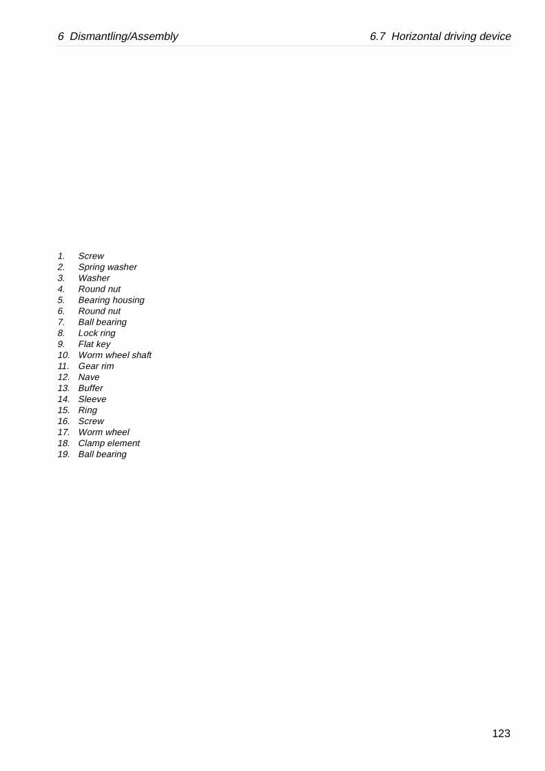
6 Dismantling/Assembly 6.7 Horizontal driving device
1. Screw2. Spring washer3. Washer4. Round nut5. Bearing housing6. Round nut7. Ball bearing8. Lock ring9. Flat key10. Worm wheel shaft11. Gear rim12. Nave13. Buffer14. Sleeve15. Ring16. Screw17. Worm wheel18. Clamp element19. Ball bearing
123
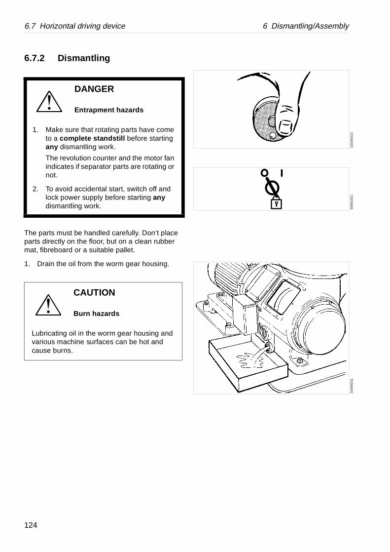
6.7 Horizontal driving device 6 Dismantling/Assembly
G0
246
221
S00
5101
1G
048
4211
6.7.2 Dismantling
The parts must be handled carefully. Don’t place parts directly on the floor, but on a clean rubber mat, fibreboard or a suitable pallet.
1. Drain the oil from the worm gear housing.
DANGER
Entrapment hazards
1. Make sure that rotating parts have come to a complete standstill before starting any dismantling work.
The revolution counter and the motor fan indicates if separator parts are rotating or not.
2. To avoid accidental start, switch off and lock power supply before starting any dismantling work.
CAUTION
Burn hazards
Lubricating oil in the worm gear housing and various machine surfaces can be hot and cause burns.
124
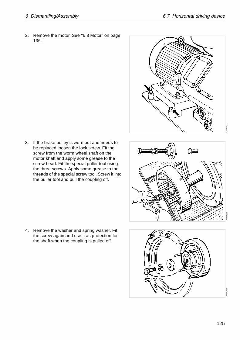
6 Dismantling/Assembly 6.7 Horizontal driving device
G0
4991
11G
048
431
1G
050
0411
2. Remove the motor. See ‘‘6.8 Motor” on page 136.
3. If the brake pulley is worn out and needs to be replaced loosen the lock screw. Fit the screw from the worm wheel shaft on the motor shaft and apply some grease to the screw head. Fit the special puller tool using the three screws. Apply some grease to the threads of the special screw tool. Screw it into the puller tool and pull the coupling off.
4. Remove the washer and spring washer. Fit the screw again and use it as protection for the shaft when the coupling is pulled off.
125

6.7 Horizontal driving device 6 Dismantling/Assembly
G0
4844
11G
0500
511
G0
797
911
G07
980
11
5. Fit the puller tool and pull off the coupling.
6. Remove the covers.
7. Shut off the water supply and disconnect the cooling water connections to the cooling coil in the worm gear housing.
8. Remove the nuts and washers fixing the cooling coil to the bearing shield and press the two tube ends up into the bearing shiled.
9. Remove the bearing shield. Ease it off by means of two of the fastening bolts.
10. Lift out the cooling coil. Take care of the sealings (A).
CAUTION
Crush hazards
The shield is quite heavy. Hold the shield firmly or use two longer screws as guide pins so as not to drop it during dismantling.
126

6 Dismantling/Assembly 6.7 Horizontal driving device
G0
212
511
G0
2128
11G
019
2311
11. Fit the puller tool and pull off the ball bearing.
12. Loosen the clamp screws uniformly and successively around the clamping rings in the order shown in the illustration. At the first round, do not loosen them more than 1/4 turn to avoid twisting the clamping rings. Do not screw out the clamp screws entirely.
13. Remove the clamping element and the worm wheel.
14. Remove the lock ring.
Left-hand thread!
CAUTION
Crush hazards
The worm wheel is quite heavy. Hold it firmly when dismantling. Risk for jamming injury.
Be careful not to get fingers trapped.
127
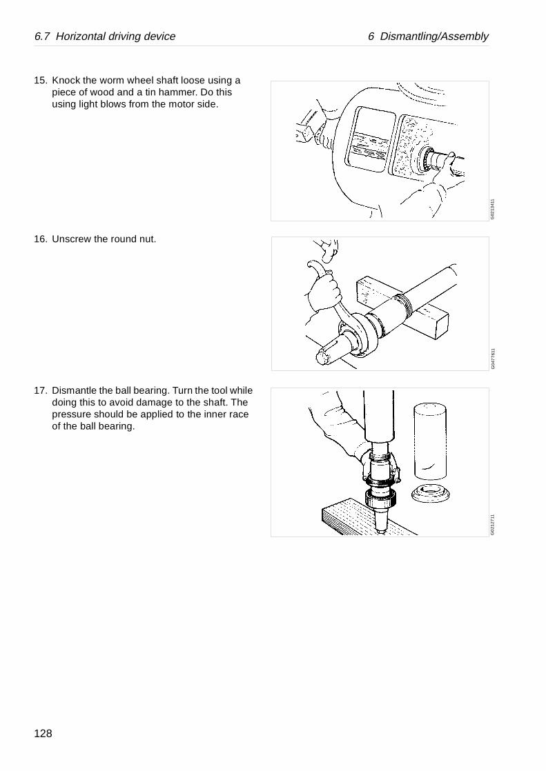
6.7 Horizontal driving device 6 Dismantling/Assembly
G02
1341
1G
047
761
1G
021
2711
15. Knock the worm wheel shaft loose using a piece of wood and a tin hammer. Do this using light blows from the motor side.
16. Unscrew the round nut.
17. Dismantle the ball bearing. Turn the tool while doing this to avoid damage to the shaft. The pressure should be applied to the inner race of the ball bearing.
128
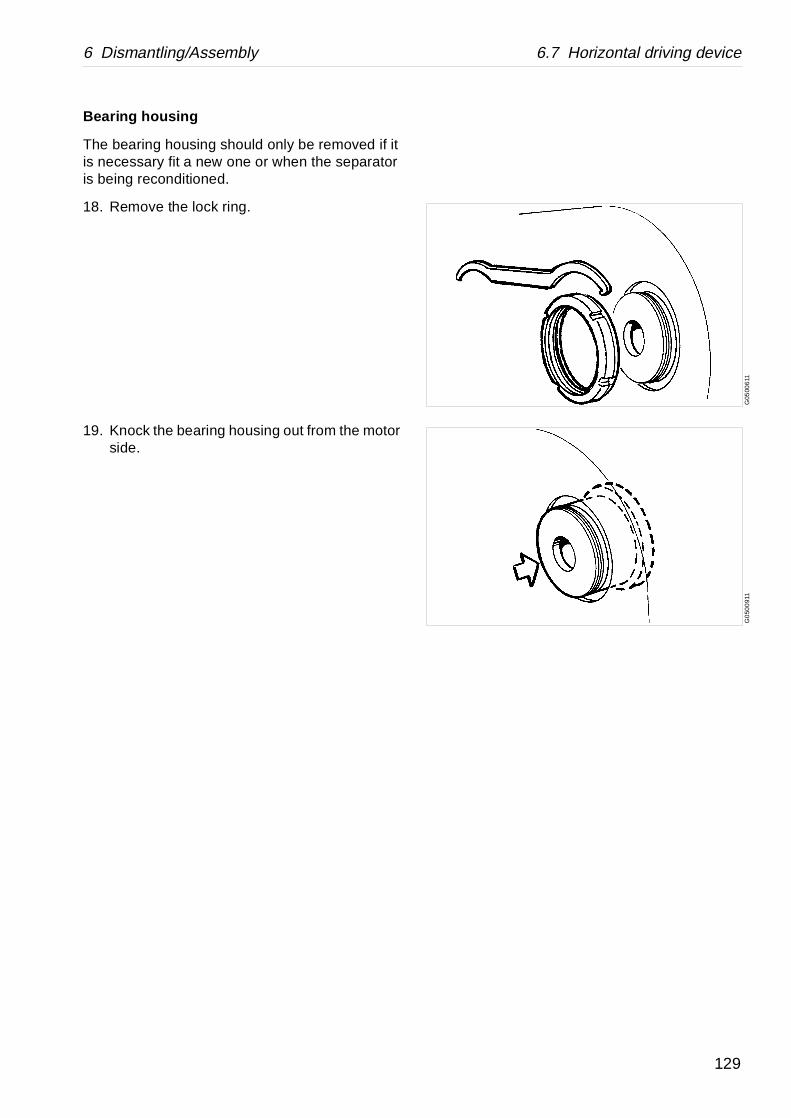
6 Dismantling/Assembly 6.7 Horizontal driving device
G05
006
11G
050
091
1
Bearing housing
The bearing housing should only be removed if it is necessary fit a new one or when the separator is being reconditioned.
18. Remove the lock ring.
19. Knock the bearing housing out from the motor side.
129

6.7 Horizontal driving device 6 Dismantling/Assembly
G05
0071
1G
050
101
1G
0501
111
6.7.3 Assembly
Check points‘‘5.3.1 Corrosion” on page 47.‘‘5.3.2 Cracks” on page 49.‘‘5.3.3 Erosion” on page 50.‘‘5.3.9 Worm wheel and worm; wear of teeth” on page 59.‘‘5.4.2 Brake” on page 61.
1. Apply Loctite 242 to the guide surface of the bearing housing and fit it to the frame if it has been removed.
2. Lock the bearing housing with the lock ring.
3. Clean and oil the bearing seat on the worm wheel shaft.
130
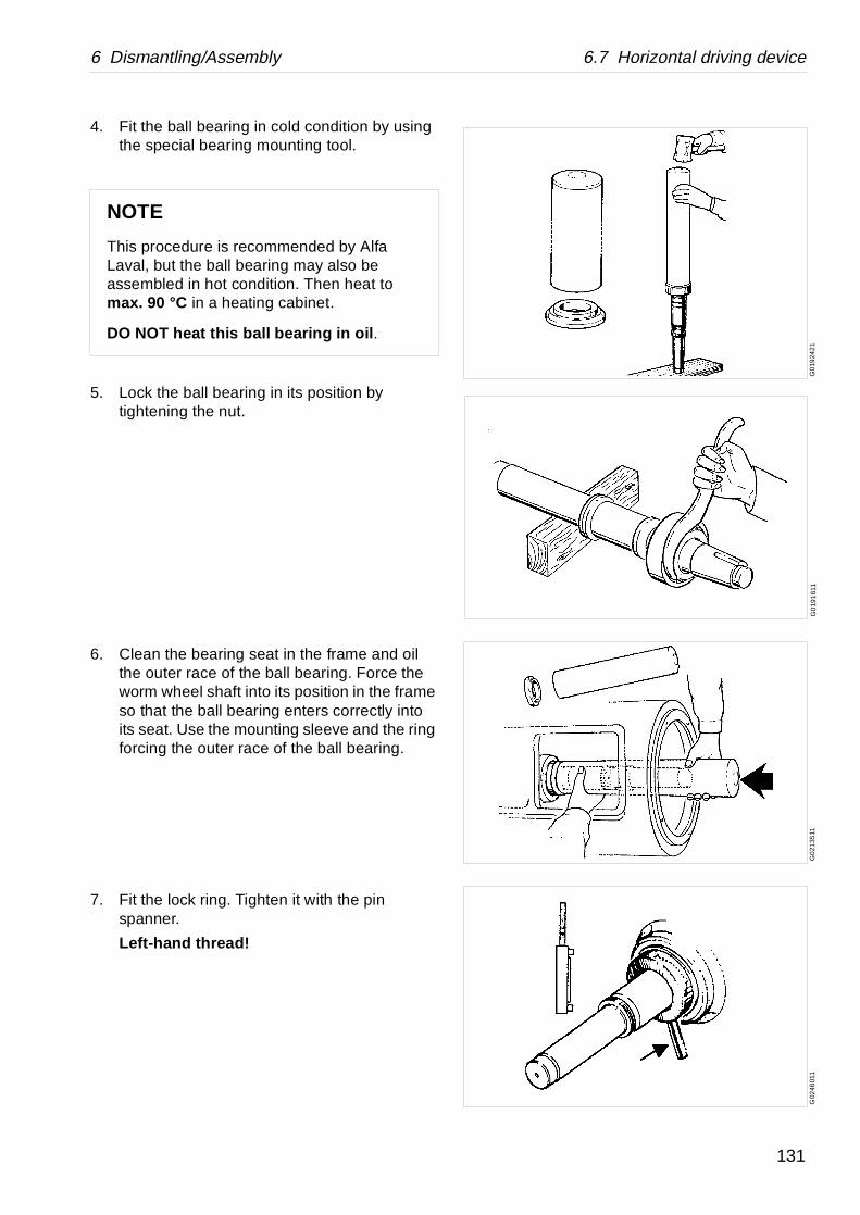
6 Dismantling/Assembly 6.7 Horizontal driving device
G0
1924
21
G0
191
611
G0
2135
11G
0246
011
4. Fit the ball bearing in cold condition by using the special bearing mounting tool.
5. Lock the ball bearing in its position by tightening the nut.
6. Clean the bearing seat in the frame and oil the outer race of the ball bearing. Force the worm wheel shaft into its position in the frame so that the ball bearing enters correctly into its seat. Use the mounting sleeve and the ring forcing the outer race of the ball bearing.
7. Fit the lock ring. Tighten it with the pin spanner.
Left-hand thread!
NOTE
This procedure is recommended by Alfa Laval, but the ball bearing may also be assembled in hot condition. Then heat to max. 90 °C in a heating cabinet.
DO NOT heat this ball bearing in oil .
131
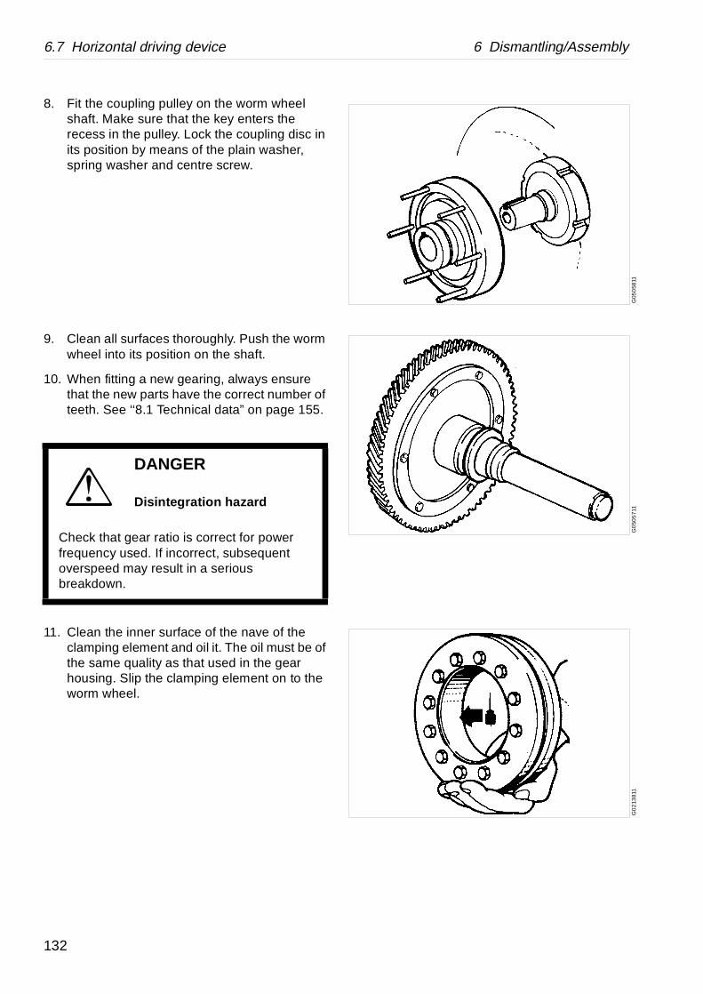
6.7 Horizontal driving device 6 Dismantling/Assembly
G05
058
11G
050
571
1G
02
1381
1
8. Fit the coupling pulley on the worm wheel shaft. Make sure that the key enters the recess in the pulley. Lock the coupling disc in its position by means of the plain washer, spring washer and centre screw.
9. Clean all surfaces thoroughly. Push the worm wheel into its position on the shaft.
10. When fitting a new gearing, always ensure that the new parts have the correct number of teeth. See ‘‘8.1 Technical data” on page 155.
11. Clean the inner surface of the nave of the clamping element and oil it. The oil must be of the same quality as that used in the gear housing. Slip the clamping element on to the worm wheel.
DANGER
Disintegration hazard
Check that gear ratio is correct for power frequency used. If incorrect, subsequent overspeed may result in a serious breakdown.
132

6 Dismantling/Assembly 6.7 Horizontal driving device
G02
0781
1G
048
5611
G0
7980
21
G07
9791
1
12. First tighten the three clamp screws A, B and C (see figure), but only so that clamping element just sticks on the worm wheel shaft.
Then tighten the clamp screws uniformly and successively around the clamping ring in order (1-12) as shown in the figure. Do not tighten crosswise.
Tightening torque: 29 Nm.
This must be repeated several turns around until full torque on every screws is reached.
Check continuously that the clamping rings remain parallel.
13. Heat the ball bearing in oil or in a heating cabinet. Fit the bearing. When it has cooled down, use the mounting disc and strike a few blows on the latter to make sure that the bearing is in the correct position. Use the tin hammer.
14. Make certain that the worm gear housing and the magnet of the cooling coil have been properly cleaned.
Fit new gaskets (A) onto the cooling coil tubes and insert the coil.
15. Clean the bearing seat in the end shield.
16. Make sure the tolerance ring in the shield is correctly fitted.
17. Fit the sealings onto the cooling coil tubes. Fit the gasket on the bearing shield and fit the shield. If necessary, force the shield into position by tightening the screws in the shield, or knock carefully with a tin hammer against the central part of the shield.
18. Fit the bearing shield cover and the nuts and washers of the cooling coil connections.
133
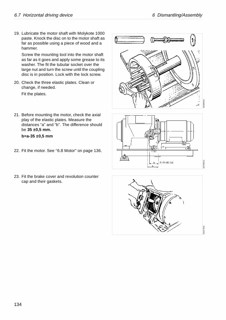
6.7 Horizontal driving device 6 Dismantling/Assembly
G0
485
911
G07
9011
1G
012
7911
19. Lubricate the motor shaft with Molykote 1000 paste. Knock the disc on to the motor shaft as far as possible using a piece of wood and a hammer.
Screw the mounting tool into the motor shaft as far as it goes and apply some grease to its washer. The fit the tubular socket over the large nut and turn the screw until the coupling disc is in position. Lock with the lock screw.
20. Check the three elastic plates. Clean or change, if needed.
Fit the plates.
21. Before mounting the motor, check the axial play of the elastic plates. Measure the distances “a” and “b”. The difference should be 35 ±0,5 mm.
b=a-35 ±0,5 mm
22. Fit the motor. See ‘‘6.8 Motor” on page 136.
23. Fit the brake cover and revolution counter cap and their gaskets.
134
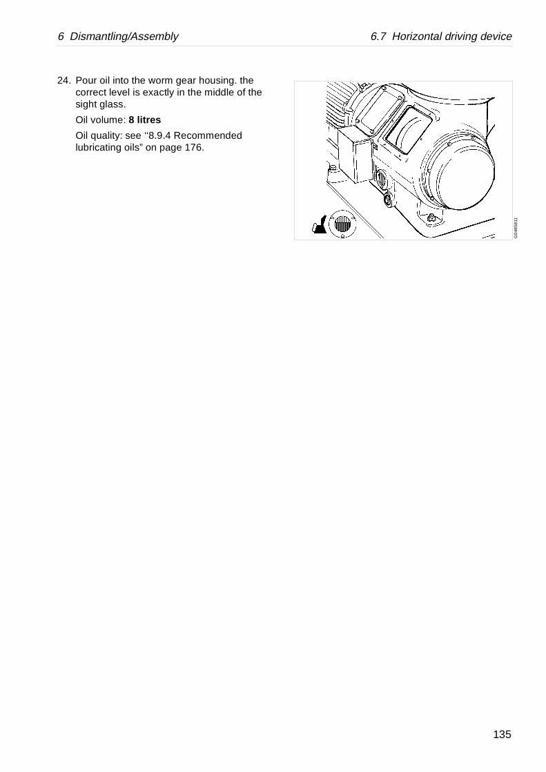
6 Dismantling/Assembly 6.7 Horizontal driving device
G0
4858
11
24. Pour oil into the worm gear housing. the correct level is exactly in the middle of the sight glass.
Oil volume: 8 litres
Oil quality: see ‘‘8.9.4 Recommended lubricating oils” on page 176.
135

6.8 Motor 6 Dismantling/Assembly
G0
788
421
6.8 Motor
6.8.1 Drawings
1. Motor2. Bottom frame3. Screw4. Taper pins5. Taper pins6. Screw
136
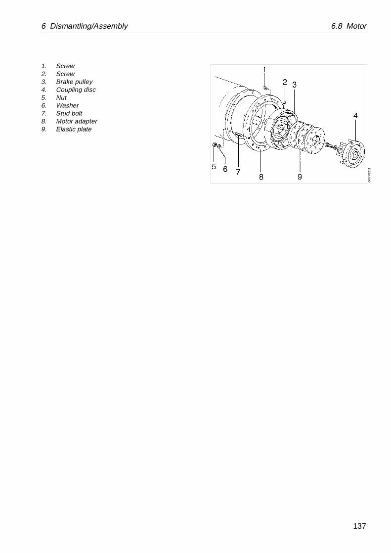
6 Dismantling/Assembly 6.8 Motor
G07
782
11
1. Screw2. Screw3. Brake pulley4. Coupling disc5. Nut6. Washer7. Stud bolt8. Motor adapter9. Elastic plate
137

6.8 Motor 6 Dismantling/Assembly
G02
4622
1S
005
101
1G
078
843
1
1. Taper pin2. Screw
6.8.2 Dismantling
1. Loosen the electric cables to the motor.
2. Remove the two taper pins (1).
3. Unscrew the four screws (2) in the motor feet.
4. Hook up the motor in a hoist.
5. Lift the motor slightly.
6. Pull out the motor from the separator frame and lift it away.
DANGER
Entrapment hazards
1. Make sure that rotating parts have come to a complete standstill before starting any dismantling work.
The revolution counter and the motor fan indicates if separator parts are rotating or not.
2. To avoid accidental start, switch off and lock power supply before starting any dismantling work.
138

6 Dismantling/Assembly 6.8 Motor
G07
776
11
A. Position of the three holes for the puller tool
7. Remove the three elastic plates.
8. If brake pulley has to be dismantled, use the special dismounting tool together with a washer to protect the threaded hole (if any) in the motor shaft. See ‘‘6.7.2 Dismantling” on page 124.
139
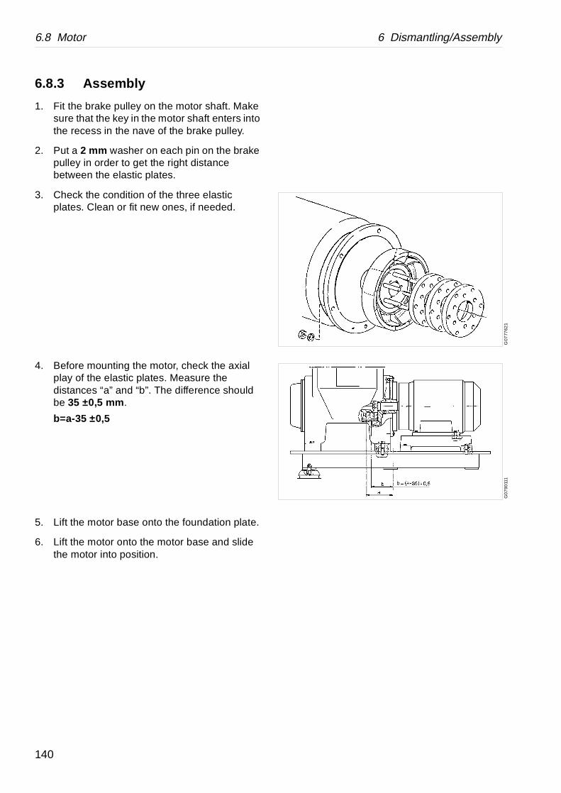
6.8 Motor 6 Dismantling/Assembly
G07
7762
1G
07
9011
1
6.8.3 Assembly
1. Fit the brake pulley on the motor shaft. Make sure that the key in the motor shaft enters into the recess in the nave of the brake pulley.
2. Put a 2 mm washer on each pin on the brake pulley in order to get the right distance between the elastic plates.
3. Check the condition of the three elastic plates. Clean or fit new ones, if needed.
4. Before mounting the motor, check the axial play of the elastic plates. Measure the distances “a” and “b”. The difference should be 35 ±0,5 mm .
b=a-35 ±0,5
5. Lift the motor base onto the foundation plate.
6. Lift the motor onto the motor base and slide the motor into position.
140
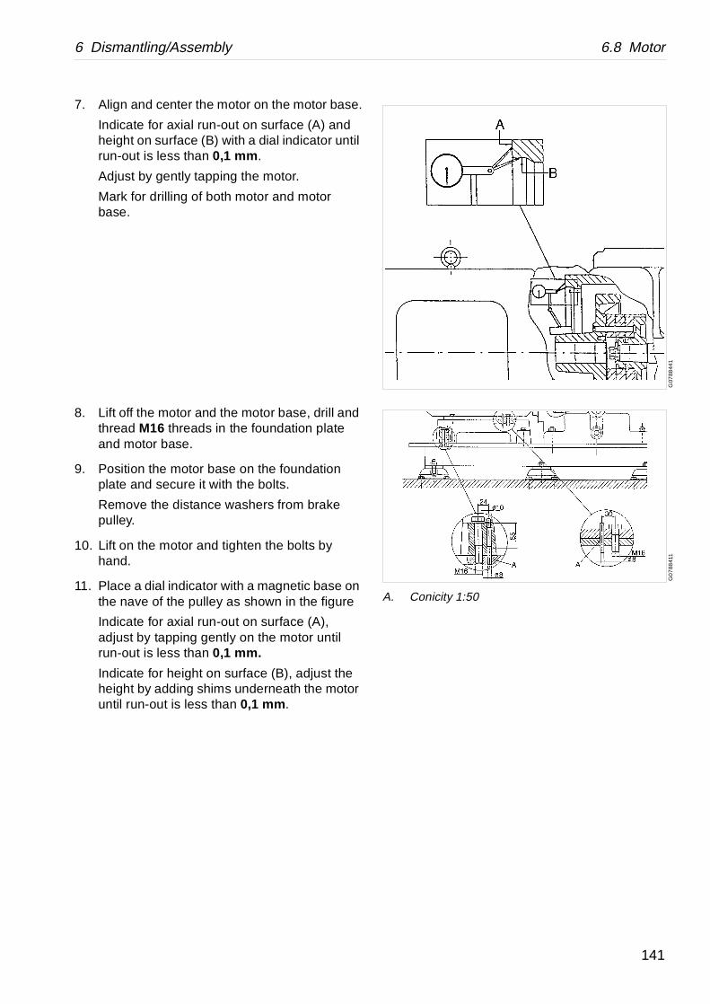
6 Dismantling/Assembly 6.8 Motor
G07
8844
1G
07
8841
1
A. Conicity 1:50
7. Align and center the motor on the motor base.
Indicate for axial run-out on surface (A) and height on surface (B) with a dial indicator until run-out is less than 0,1 mm .
Adjust by gently tapping the motor.
Mark for drilling of both motor and motor base.
8. Lift off the motor and the motor base, drill and thread M16 threads in the foundation plate and motor base.
9. Position the motor base on the foundation plate and secure it with the bolts.
Remove the distance washers from brake pulley.
10. Lift on the motor and tighten the bolts by hand.
11. Place a dial indicator with a magnetic base on the nave of the pulley as shown in the figure
Indicate for axial run-out on surface (A), adjust by tapping gently on the motor until run-out is less than 0,1 mm.
Indicate for height on surface (B), adjust the height by adding shims underneath the motor until run-out is less than 0,1 mm .
141
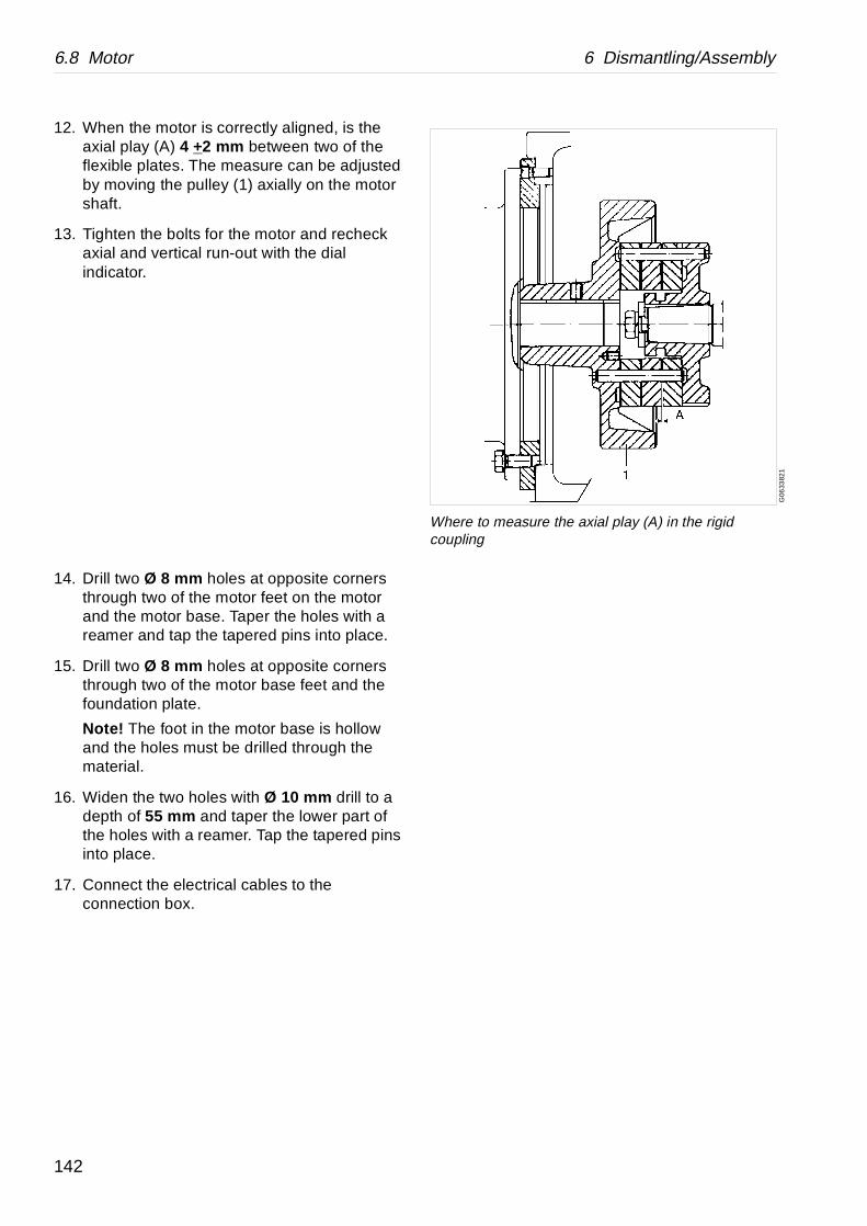
6.8 Motor 6 Dismantling/Assembly
G06
3382
1
Where to measure the axial play (A) in the rigid coupling
12. When the motor is correctly aligned, is the axial play (A) 4 +2 mm between two of the flexible plates. The measure can be adjusted by moving the pulley (1) axially on the motor shaft.
13. Tighten the bolts for the motor and recheck axial and vertical run-out with the dial indicator.
14. Drill two Ø 8 mm holes at opposite corners through two of the motor feet on the motor and the motor base. Taper the holes with a reamer and tap the tapered pins into place.
15. Drill two Ø 8 mm holes at opposite corners through two of the motor base feet and the foundation plate.
Note! The foot in the motor base is hollow and the holes must be drilled through the material.
16. Widen the two holes with Ø 10 mm drill to a depth of 55 mm and taper the lower part of the holes with a reamer. Tap the tapered pins into place.
17. Connect the electrical cables to the connection box.
142
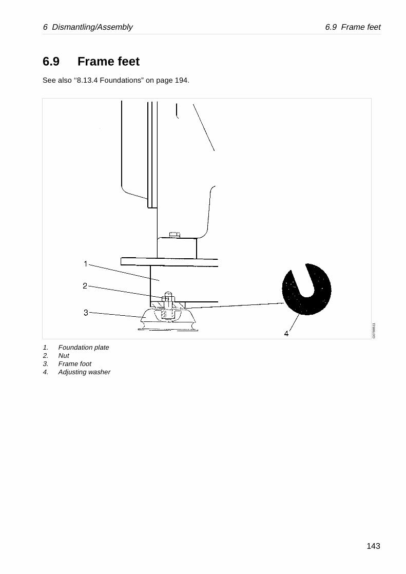
6 Dismantling/Assembly 6.9 Frame feet
G07
885
11
6.9 Frame feetSee also ‘‘8.13.4 Foundations” on page 194.
1. Foundation plate2. Nut3. Frame foot4. Adjusting washer
143

6.9 Frame feet 6 Dismantling/Assembly
6.9.1 Dismantling
Applicable when removing the separator from one place to another.
1. If the separator has to be removed loosen the frame foot nuts.
2. Lift off the separator according to ‘‘5.5 Lifting instructions” on page 66.
6.9.2 Assembly
1. Place the separator in its position.
2. Mark out the foundation positions for screw holes for the anchoring bolts.
3. Remove the separator and drill the holes.
4. Mount the anchoring bolts on the foundation.
5. Place the separator with its foundation on the anchoring bolts. Place the bowl in the separator frame.
6. Check horizontal alignment of the foundation plate. If necessary, add adjusting washers to get the frame horizontal.
For max. horizontal deviation see chapter ‘‘8.10.1 Foundation drawing” on page 178.
144
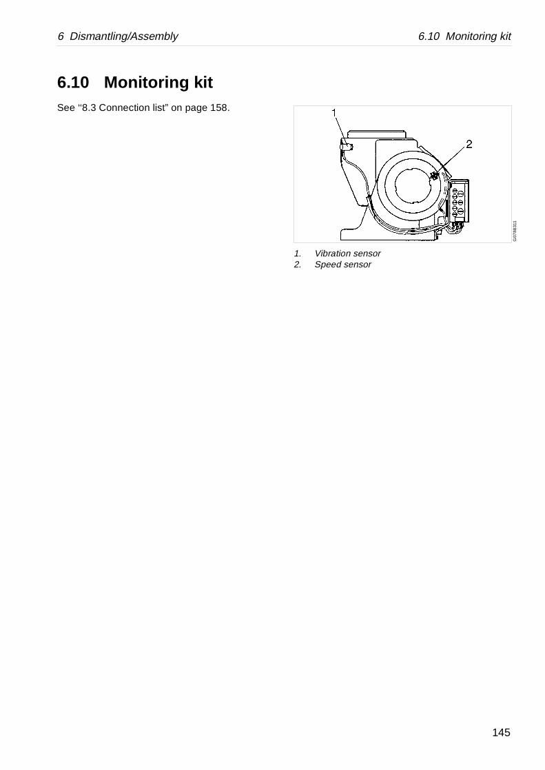
6 Dismantling/Assembly 6.10 Monitoring kit
G07
8831
1
1. Vibration sensor2. Speed sensor
6.10 Monitoring kitSee ‘‘8.3 Connection list” on page 158.
145
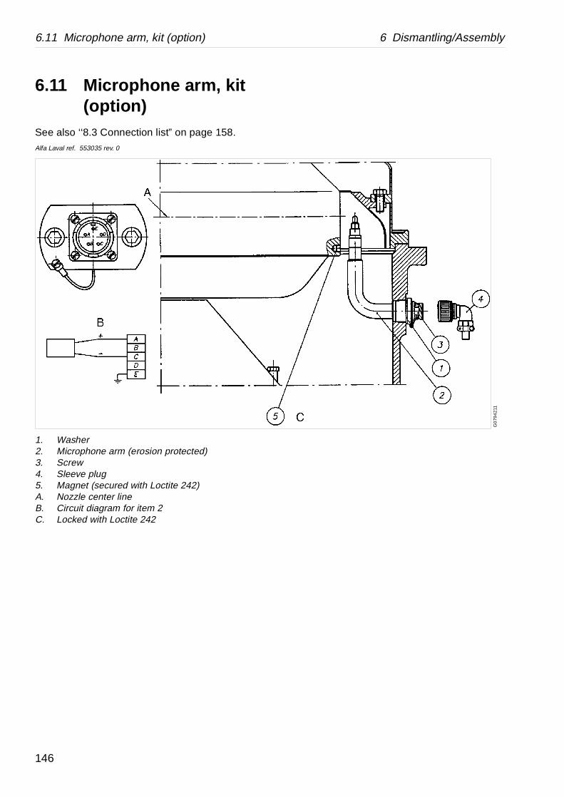
6.11 Microphone arm, kit (option) 6 Dismantling/Assembly
G0
794
211
6.11 Microphone arm, kit (option)
See also ‘‘8.3 Connection list” on page 158.Alfa Laval ref. 553035 rev. 0
1. Washer2. Microphone arm (erosion protected)3. Screw4. Sleeve plug5. Magnet (secured with Loctite 242)A. Nozzle center lineB. Circuit diagram for item 2C. Locked with Loctite 242
146
7 Trouble-Tracing
Contents
7.1 Mechanical faults 149
7.2 Clarification faults 151
147

148
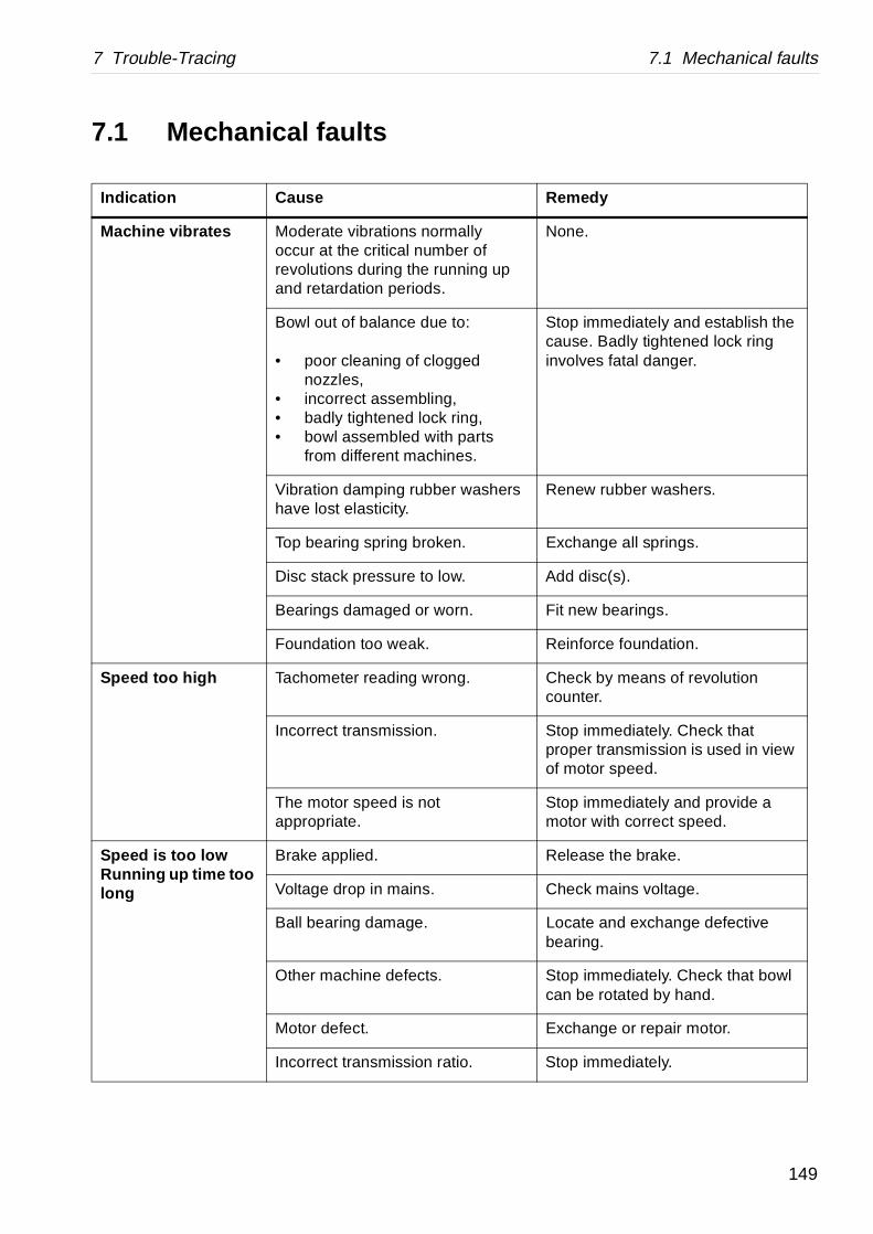
7 Trouble-Tracing 7.1 Mechanical faults
Remedy
lly r of ing up
None.
:
ed
ng, arts s.
Stop immediately and establish the cause. Badly tightened lock ring involves fatal danger.
washers Renew rubber washers.
. Exchange all springs.
. Add disc(s).
n. Fit new bearings.
Reinforce foundation.
. Check by means of revolution counter.
Stop immediately. Check that proper transmission is used in view of motor speed.
Stop immediately and provide a motor with correct speed.
Release the brake.
Check mains voltage.
Locate and exchange defective bearing.
Stop immediately. Check that bowl can be rotated by hand.
Exchange or repair motor.
o. Stop immediately.
7.1 Mechanical faults
Indication Cause
Machine vibrates Moderate vibrations normaoccur at the critical numberevolutions during the runnand retardation periods.
Bowl out of balance due to
• poor cleaning of cloggnozzles,
• incorrect assembling, • badly tightened lock ri• bowl assembled with p
from different machine
Vibration damping rubber have lost elasticity.
Top bearing spring broken
Disc stack pressure to low
Bearings damaged or wor
Foundation too weak.
Speed too high Tachometer reading wrong
Incorrect transmission.
The motor speed is not appropriate.
Speed is too lowRunning up time too long
Brake applied.
Voltage drop in mains.
Ball bearing damage.
Other machine defects.
Motor defect.
Incorrect transmission rati
149

7.1 Mechanical faults 7 Trouble-Tracing
t.
t. Exchange or repair motor.
Release the brake.
Locate and exchange defective bearing.
See – Speed is too low.
Exchange or clean lining.
Drain water and change oil.
Drain water and change oil.
Exchange seal rings and packings. Change the oil.
Check quantity and quality.
. Exchange worn parts. Exchange of complete gear in generally advisable.
ged. Exchange bearing.
upling Adjust.
See – “Speed too low”.
Release the brake.
Feel over machine and locate spot. Exchange bearing.
Trace cause. Adjust overcurrent relay, if any provided.
Remedy
Starting power too low
Ammeter reading incorrec
Starting power too high
Ammeter reading incorrec
Motor defect.
Brake applied.
Ball bearing damaged.
Other machine defects.
Retardation time too long
Brake lining worn or oily.
Water in worm gear housing
Condensation.
Water flushing by externalcleaning.
Leakage via top bearing.
Noise from worm gear housing
Oil quantity Incorrect.
Worm wheel or worm worn
Ball bearing worn or dama
Noise from rigid coupling
Incorrect play between codisc and brake pulley.
Speed too low.
Smell Brake applied.
Bearing running hot.
Motor overheated.
Indication Cause
150
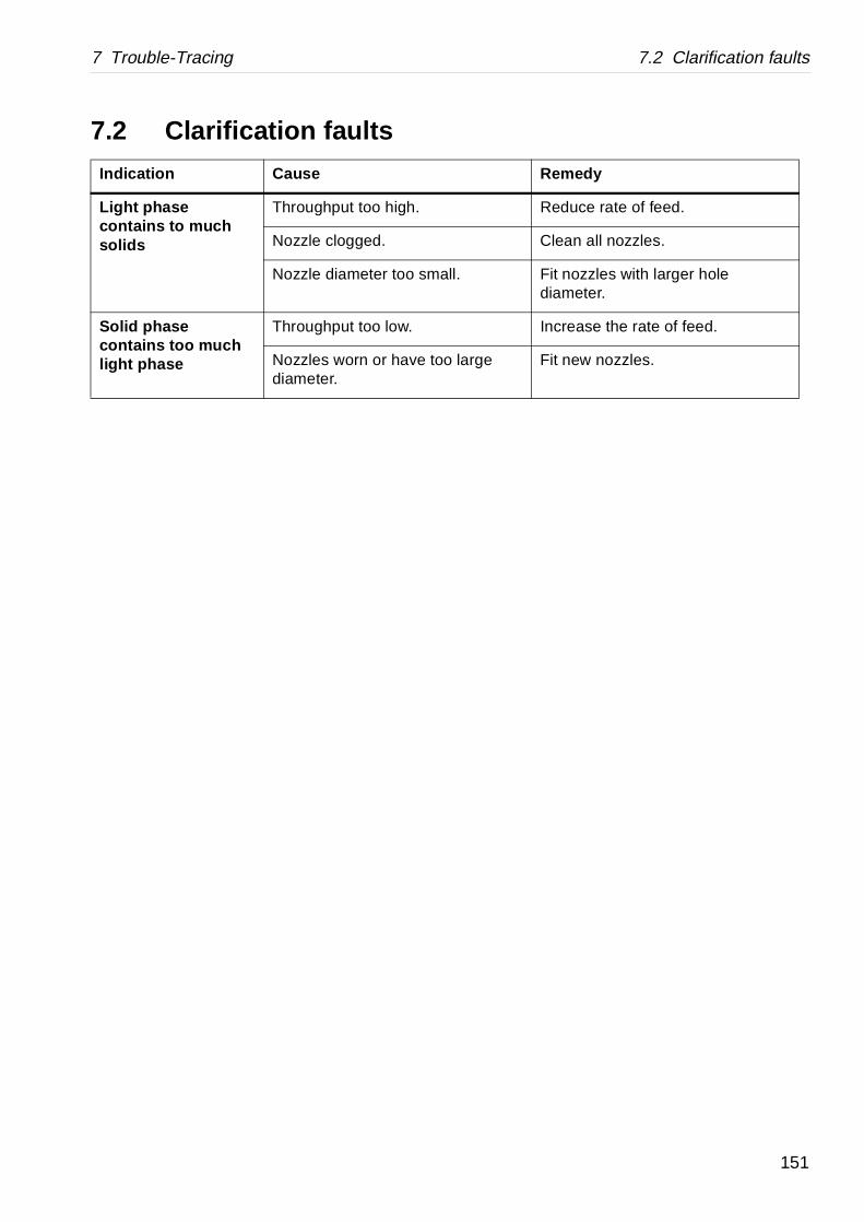
7 Trouble-Tracing 7.2 Clarification faults
Remedy
Reduce rate of feed.
Clean all nozzles.
. Fit nozzles with larger hole diameter.
Increase the rate of feed.
large Fit new nozzles.
7.2 Clarification faults
Indication Cause
Light phase contains to much solids
Throughput too high.
Nozzle clogged.
Nozzle diameter too small
Solid phase contains too much light phase
Throughput too low.
Nozzles worn or have too diameter.
151

7.2 Clarification faults 7 Trouble-Tracing
152
8 Technical Reference
Contents
8.1 Technical data 155
8.2 Basic size drawing 156
8.2.1 Separator excl. connections 156
8.2.2 Dimensions of connections 157
8.3 Connection list 158
8.4 Interface description 160
8.4.1 General 160
8.4.2 Definitions 160
8.4.3 Component description and Signal processing 161
8.4.4 Function graph and running limitations 165
8.5 Outlet nozzles 166
8.5.1 Choice of nozzle diameter 166
8.6 Revolution counter 167
8.7 Compressed air 168
8.8 Water quality 169
8.9 Lubricants 171
8.9.1 Introduction 171
8.9.2 Alfa Laval Lubricating Oil Groups 172
8.9.3 Recommended lubricants 174
8.9.4 Recommended lubricating oils 176
8.9.5 Recommended oil brands 177
8.10 Other drawings 178
8.10.1 Foundation drawing 178
8.10.2 Electric motor 180
8.10.3 Electric motor 182
8.10.4 Motor drive data 184
8.11 Machine plates and safety labels 186
8.12 Interconnection diagram 189
8.13 Storage and installation 190
8.13.1 Introduction 190
8.13.2 Storage and transport of goods 190
8.13.3 Planning of installation 192
8.13.4 Foundations 194
8.13.5 Preparations before first start 195
153

154

8 Technical Reference 8.1 Technical data
eters (type of liquid, rotational speed, r and in the Purchase order documents.
changes outside these parameters are made.
-03
512S-35CG
5 rev/min 50 Hz / 60 Hz
0 rev/min 50 Hz / 60 Hz
34 50 Hz / 60 Hz
m3/h
m3/h
0 kg/m3
min/max °C
°C
kg (without motor)
kW
kW (idling/at max. capacity)
minutes (min/max)
minutes (min/max)
litres
minutes
dB(A)
mm/sec (new sep/sep in use)
mm/sec (1st/2nd)
mm
litres
kg
ontact with process liquid.
8.1 Technical dataAlfa Laval ref. 560864, rev. 0
DANGER
Disintegration hazards
Use the separator only for the purpose and paramtemperature, density etc.) specified in this chapte
Consult your Alfa Laval representative before any
Product number 881119-01
Separator type CH/FESX
Bowl speed max 4800/476
Speed motor shaft max 1500/180
Gear ratio 96:30/90:
Hydraulic capacity 70
Max. nozzle flow with water 23
Max density of sediment/feed 1700/120
Feed temperature 0/100
Ambient temperature +5 to +55
Weight of separator 1700
Motor power 37/55
Power consumption 6/55
Starting time 3/5
Stopping time with brake 4/7
Lubricating oil volume 8
Max running time empty bowl 180
Sound press level 87
Vibration level max. according to PF 9/14
Alarm levels for vibration monitor 6/8
Bowl max inner diameter 555
Bowl volume 31
Bowl weight 320
There are no other material than stainless steel in c
155
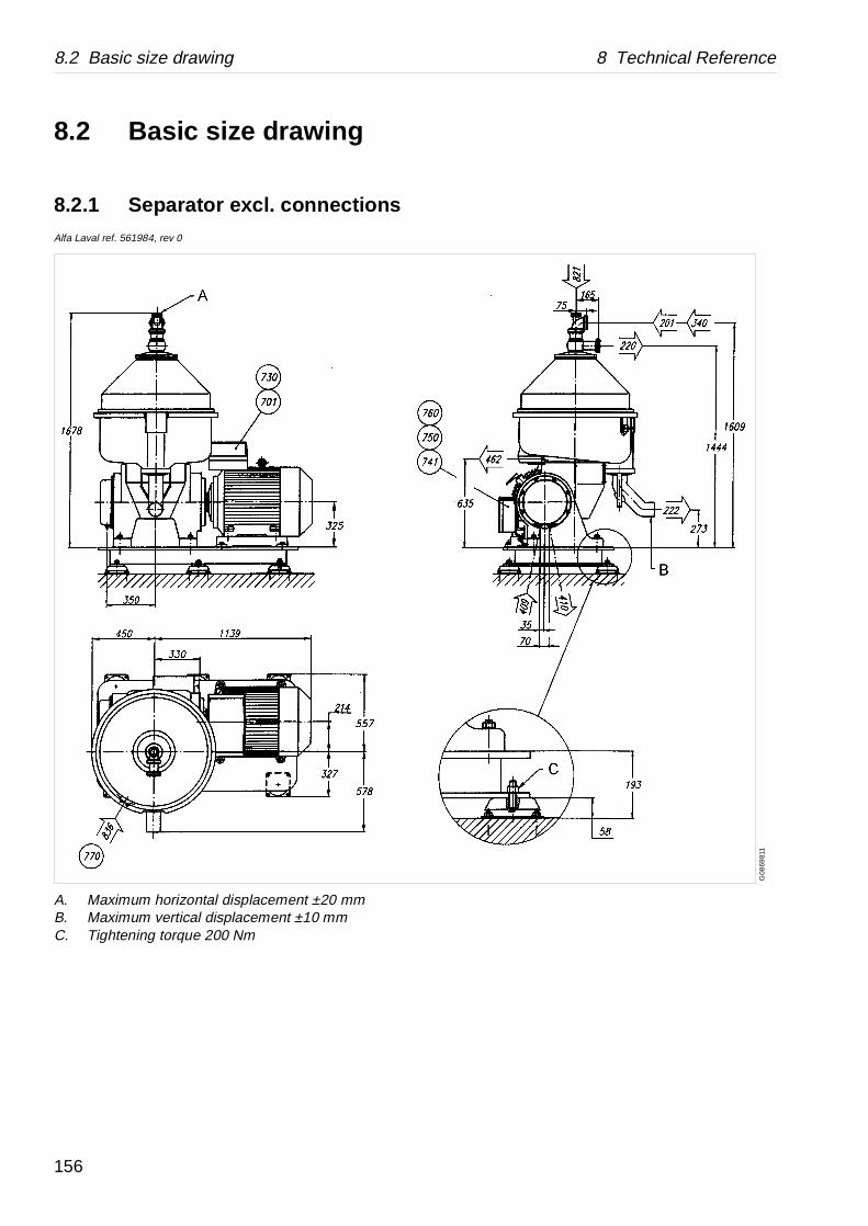
8.2 Basic size drawing 8 Technical Reference
G08
6981
1
8.2 Basic size drawing
8.2.1 Separator excl. connectionsAlfa Laval ref. 561984, rev 0
A. Maximum horizontal displacement ±20 mmB. Maximum vertical displacement ±10 mmC. Tightening torque 200 Nm
156

8 Technical Reference 8.2 Basic size drawing
G0
869
821
8.2.2 Dimensions of connectionsAlfa Laval ref. 561984, rev 0
Data for connections see ‘‘8.3 Connection list” on page 158.
All connections to be installed non-loaded and flexible.
157

8.3 Connection list 8 Technical Reference
Requirements / limits
0-100 °C
1200 kg/m3
70 m3/h
70 m3/h
The outlet should be installed in such a way that you can not fill the outlet with sludge (open outlet).
1700 kg/m3
23 m3/h
The outlet should be installed in such a way that you can not fill the sediment outlet with sludge (open outlet).
26 m3/h
80-100 litres/h
max. 50 kPa
Open
Should be possible to drain liquids by gravity.
±5%
±10%
PTC-thermistors 190 °C
8.3 Connection listAlfa Laval ref. 561983, rev. 0
No. Description
201 Inlet for product
• Allowed temperature
• Max. allowed density
• Max. allowed flow
220 Outlet for clarified liquid
• Max. allowed flow
222 Outlet for solid phase
• Max. allowed sediment density
• Max. allowed flow
Nozzle Nozzledimension flow0,80 mm 3,0 m3/h0,90 mm 3,8 m3/h1,00 mm 4,7 m3/h1,15 mm 6,2m3/h1,30 mm 7,9 m3/h1,45 mm 9,9 m3/h1,60 mm 12,0 m3/h1,80 mm 15,2 m3/h2,00 mm 18,7 m3/h2,25 mm 23,0 m3/h
340 Inlet for safety/back up liquid
• Min. flow
409 Inlet for water to oil cooler.
• Consuption
• Pressure
410 Outlet from oil cooler.
462 Drain of frame top part.
701 Motor for separator
• Allowed frequency variation
• Momentarily during max. 5 sec.
730 Temperature sensor motor winding
Type
158
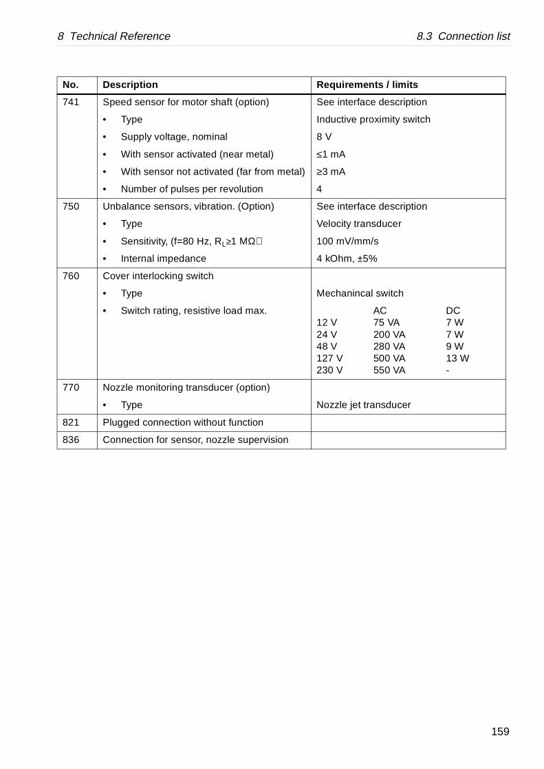
8 Technical Reference 8.3 Connection list
See interface description
Inductive proximity switch
8 V
≤1 mA
etal) ≥3 mA
4
See interface description
Velocity transducer
100 mV/mm/s
4 kOhm, ±5%
Mechanincal switch
AC DC12 V 75 VA 7 W24 V 200 VA 7 W48 V 280 VA 9 W127 V 500 VA 13 W230 V 550 VA -
Nozzle jet transducer
Requirements / limits
741 Speed sensor for motor shaft (option)
• Type
• Supply voltage, nominal
• With sensor activated (near metal)
• With sensor not activated (far from m
• Number of pulses per revolution
750 Unbalance sensors, vibration. (Option)
• Type
• Sensitivity, (f=80 Hz, RL≥1 MΩ)
• Internal impedance
760 Cover interlocking switch
• Type
• Switch rating, resistive load max.
770 Nozzle monitoring transducer (option)
• Type
821 Plugged connection without function
836 Connection for sensor, nozzle supervision
No. Description
159
8.4 Interface description 8 Technical Reference
8.4 Interface descriptionAlfa Laval ref. 557279, rev.3
8.4.1 General
In addition to the Connection List this document describes limitations and conditions for safe control, monitoring and reliable operation. At the end of the document a function graph and running limitations are found.
8.4.2 Definitions
Stand still (Ready for start) means:
• The machine is assembled correctly.
• All connections are installed according to Connection list, Interconnection diagram, Motor drive data and Interface description.
Start means
• The power to the separator motor is on.
• The bowl must be kept filled.
• The acceleration is supervised to ensure that a certain speed has been reached within a certain time.
The start procedure continues until the Y-D switch-over has been made and a stabilization period has passed (about 1 minute). See document Motor drive data.
Normal stop means
• Stopping of the machine at any time with brake applied.
• The bowl must be kept filled.
160

8 Technical Reference 8.4 Interface description
Safety stop means
The machine must be stopped in the quickest and safest way due to vibration or process reasons.
Comply to following conditions:
• The bowl must be kept filled.
• The machine must not be restarted before the reason for the Safety stop has been investigated and action has been taken.
In case of emergency condition in the plant, the machine must be stopped in a way that is described in EN 418.
8.4.3 Component description and Signal processing
Hydraulic connec tions
Inlet for product 201
The product flow to the machine can start when the stabilizing period after Y-D switch over has run out. When product flow starts it replaces the safety/back up liquid. This should be done gradually during 10 to 60 seconds . When the product flow stops it must immediately be replaced by safety/back up liquid to avoid unbalance in the separator bowl.
The particle size in the product flow must not exceed 80% of the installed nozzle diameter, to minimize the risk of clogged nozzles, which can cause unbalance in the separator bowl.
161

8.4 Interface description 8 Technical Reference
Inlet for safety/back up liquid 340
The machine must never be run without the bowl being completely filled with liquid. The safety/back up liquid is e.g. to compensate for a possible loss of feed flow to the separator. The safety/back up liquid must be activated instantly otherwise there is a potential risk for critical unbalance due to an uneven build up of solids. Solid build ups can be caused by clogged nozzles etc.
In order to provide safety/back up liquid instantly the pipe length between safety/back up liquid valve and the separator should be as short as possible. The safety/back up liquid should be used during the start period, from 0 r/min to normal running speed. If the separator bowl has been opened and manually cleaned it may be possible to start the machine without safety/back up liquid.
The safety/back up liquid must always be used during stopping sequence, from normal running speed until the bowl is completely stopped.
The safety/back up liquid flow must never be less than 110% of the flow from the installed nozzles. In some applications the nozzles wear and the nozzle flow will increase. In those applications the safety/back up liquid flow must be increased with time.
Electric connections
Separator motor 701
The separator is equipped with a 3-phase Y-D started motor. The motor is of control torque type and built for a long starting time. The starting equipment must be dimensioned for twice the rated current of the motor and the overload relay must only be connected in the D-line.
Motor Temperature Sensor 730
The separator motor is equipped with three thermistor sensors, one in each winding. The sensors are connected in series and should be connected to a thermistor relay that trips the starting equipment when the temperature exceeds the tripping level, stated in Connection list.
162
8 Technical Reference 8.4 Interface description
Speed Sensor 741 (option)
Proximity sensor of inductive type according to DIN 19234 (NAMOUR) standard giving the number of pulses per revolution of the bowl as stated in the Connection list. The bowl speed is calculated from the gear ratio and the r/min of the motor shaft.
When supplied with rated voltage the sensor gives a current signal with a size depending if the position of the sensor head is near the metal surface or in front of a groove (non-metal).
Speed signal during start:
• The turnover to D should occur at 93-96% of the synchronous speed.
• The machine must be stopped and an alarm must be given when the speed for D-turnover has not been reached within 1,3×the starting time, specified in Technical Data.
Speed signal during normal operation:
Normal operation condition is considered to have been achieved 1 minute after D-turnover. During normal operation the speed is allowed to vary within speed limits specified below:
• When the synchronous speed exceeds more than 5%, the machine must be stopped and a high speed alarm must be given.
• When the speed falls to 7% below the synchronous speed for a period longer than 1 minute , a low speed alarm signal must be given.
• In case of sudden lack of pulses from the speed sensor an alarm, speed sensor failure, must be given. When this alarm is valid, the stop phase must be controlled by a timer.
163

8.4 Interface description 8 Technical Reference
Vibration Sensor 750 (option)
The vibration sensor is of velocity type. The signal has to be converted in a special transducer, in which the signal is compared with preset limit values. When the preset limit values are exceeded appropriate countermeasures have to be performed. The two levels are warning for acceptable vibrations and Safety stop respectively in case of extreme unbalance.
Vibration signal during start (bowl speed range of 0 - 95% of synchronous speed):
In case of a vibration signal exceeding set point for immediate safety stop during 3 seconds the machine must be stopped and an alarm should be given. The setpoint value is given in the document Technical data.
Vibration signal during normal operation:
Two levels of vibration are considered for this machine:
1. In case of a signal exceeding set point for warning during 3 seconds : A warning alarm shall be given. The machine shall be stopped manually with a normal stop sequence and the reason of the vibration investigated.
2. In case of a signal exceeding set point for immediate safety stop during 3 seconds following actions must be taken: Immediate Safety automatic stop of the machine including alarm for too high vibrations.
Nozzle monitoring transducer 770 (option)
The machine can be equipped with a nozzle monitoring device. The tip of the transducer is located in the nozzle flow. The bowl is equipped with a permanent magnet giving a triggering signal for r/min of the bowl. If the flow from the nozzles becomes blocked the monitor gives a signal to the control system and action should be taken.
164
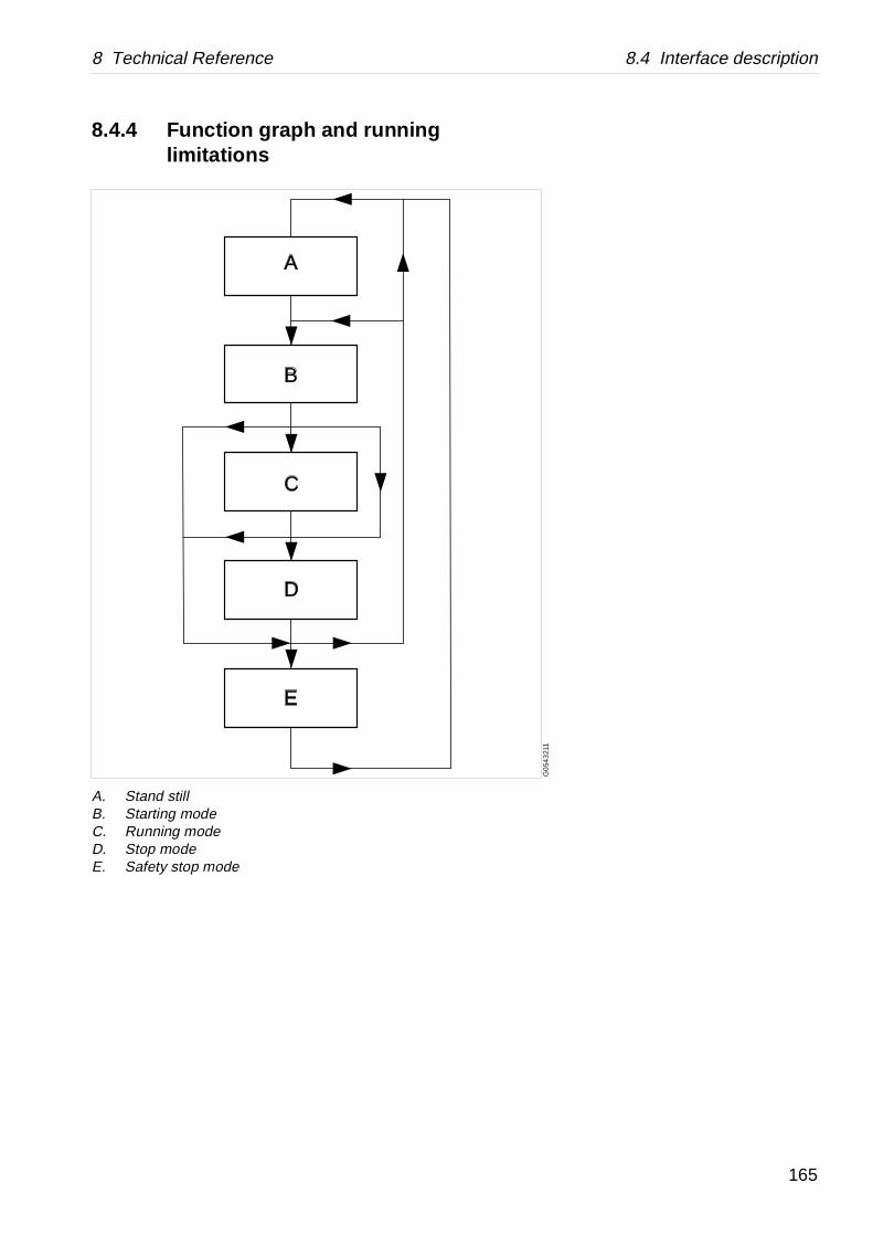
8 Technical Reference 8.4 Interface description
G0
543
211
8.4.4 Function graph and running limitations
A
B
C
D
E
A. Stand stillB. Starting modeC. Running modeD. Stop modeE. Safety stop mode
165
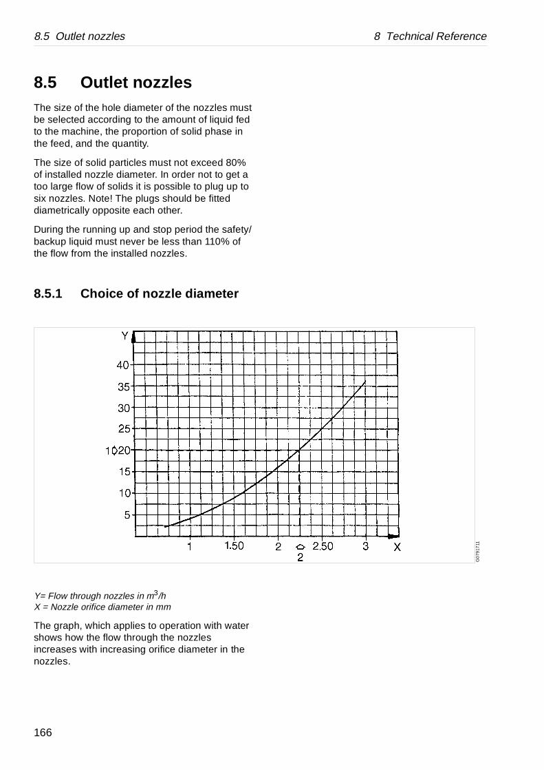
8.5 Outlet nozzles 8 Technical Reference
G0
7917
11
8.5 Outlet nozzlesThe size of the hole diameter of the nozzles must be selected according to the amount of liquid fed to the machine, the proportion of solid phase in the feed, and the quantity.
The size of solid particles must not exceed 80% of installed nozzle diameter. In order not to get a too large flow of solids it is possible to plug up to six nozzles. Note! The plugs should be fitted diametrically opposite each other.
During the running up and stop period the safety/backup liquid must never be less than 110% of the flow from the installed nozzles.
8.5.1 Choice of nozzle diameter
Y= Flow through nozzles in m3/hX = Nozzle orifice diameter in mm
The graph, which applies to operation with water shows how the flow through the nozzles increases with increasing orifice diameter in the nozzles.
166
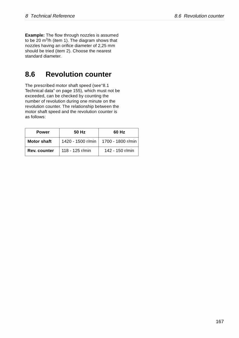
8 Technical Reference 8.6 Revolution counter
r/min
/min
Example: The flow through nozzles is assumed to be 20 m3/h (item 1). The diagram shows that nozzles having an orifice diameter of 2,25 mm should be tried (item 2). Choose the nearest standard diameter.
8.6 Revolution counterThe prescribed motor shaft speed (see‘‘8.1 Technical data” on page 155), which must not be exceeded, can be checked by counting the number of revolution during one minute on the revolution counter. The relationship between the motor shaft speed and the revolution counter is as follows:
Power 50 Hz 60 Hz
Motor shaft 1420 - 1500 r/min 1700 - 1800
Rev. counter 118 - 125 r/min 142 - 150 r
167
8.7 Compressed air 8 Technical Reference
nsmitters, quality that
e.
elow 10 micron preferably done ovided with filters.
rom oil-lubricated st possible hich it is difficult r oil separators nts. In small
alternative.
kes place at t at the air inlet, r, partially lower e (outdoor, cellar
est temperature ate in the be cooled d nozzles in the
ew of the above,
compressed air nt temperature. drier of suitable a primary
able and s, and exchange
ing from the
8.7 Compressed airAlfa Laval ref. 553407, rev. 1
The air supply to pneumatic instruments such as tracontrollers, converters, relays etc. must be of such asatisfactory function is ensured for a reasonable tim
To this end three conditions must be fulfilled:
1. Dirt in the form of solid particles down to a size b(0,01 mm) must be removed from the air. This isby means of special filters or reducing valves pr
2. Oil is always transferred to the compressed air fcompressors and must be removed to the highedegree. It constitutes a serious contamination, wto remove from the instruments. Special filters omust, therefore, be provided before the instrumeplants, oil-free compressors can be used as an
3. In the compressed-air system a condensation tavarious rates, depending on the moisture contenthe temperature before and after the compressotemperature in any cold zones passed by the pipetc.) and the like.
The air must thus be dried with regard to the lowexisting after the drying device, so that condensinstruments is avoided. Note that the air will alsothrough expansion after passing constrictions aninstruments, with condensation as a result. In vithe following must be observed:
At the inlet to an instrument, the dew point of theshould lie at least 10 °C below the lowest ambieThis is usually obtained by using an absorption capacity. If the air contains much water, provideseparator before the filter.
Air filters should be placed so as to be easily surveyaccessible in order to facilitate daily condition checkof the filter cartridge.
Alfa Laval accepts no liability for consequences arisunsatisfactorily purified compressed-air supplied by customer.
168
8 Technical Reference 8.8 Water quality
nctions: Discharge-flushing.
, corrosion and/or re be treated to meet
rtance.
volume.
areas in the
(corresponds to ature accelerates the
60mg Cl/l).
arator surfaces in pindle. Corrosion is a ting temperature, low ide concentration
n; this is accelerated n content.
tive.
e pretreated
ing from tomer.
8.8 Water qu alityAlfa Laval ref. 553406, rev. 3
Specific requirements regarding the quality of water
Water is used in the separator for several different fumechanisms, liquid seals, as cooling media and for
Bad quality of the water can with time cause erosionoperating problems in the separator and must therefocertain demands.
The following requirements are of fundamental impo
1.1 Turbidity-free water, solids content < 0,001% of
Deposits must not be allowed to form in certainseparator.
1.2 Max particle size 50 m.
2. Total hardness ≤ 180 mg CaCo3 per litre.
Chalk deposits can build-up if the water is hard 10 °dH or 12,5 °E). Increased operating temperchalk built-ups.
3. Chloride content ≤ 100 ppm NaCl (equivalent to
Chloride ions contribute to corrosion on the sepcontact with the operating water, including the sprocess that is accelerated by increased separapH, and high chloride ion concentration. A chlorabove 60 mg/l is not recommended.
4. pH > 6
Increasing acidity (lower pH) increases corrosioby increased temperatures and high chloride io
For test methods, contact any Alfa Laval representa
If these demands cannot be met, the water should baccording to Alfa Laval's recommendations.
Alfa Laval accepts no liability for consequences arisunsatisfactorily purified water s upplied by the cus
169

170

8 Technical Reference 8.9 Lubricants
ype of lubricant
Lubricating oil as specified in “Recommended lubricating oils”.
Lube oil, only a few drops for rust protection.
Lube oil.
Pastes as specified in “Recommended lubricants”.If not specified otherwise, follow the supplier’s recommendation about method of application.
Grease as specified in “Recommended lubricants”.
The bearings are packed with grease and sealed and need no extra lubrication.
Follow manufacturer’s instructions.
Note ! Some application processes demand special lubrication.
8.9 Lubricants
8.9.1 Introduction
The machine is delivered without oil in the worm gear housing. It must not be started unless oil in the quantity and of the quality prescribed has been supplied. A change of the separating temperature can make it necessary to replace the oil by oil of a different type. Lubricants, oil as well as grease, must be kept in clean, closed cans to prevent penetration of dust and moisture and to reduce the oxidizing effect to the air as far as possible. The storing room should be dry and cool.
Lubrication chartAlfa Laval ref. 553216 - 01, rev. 5
Lubricating points T
Bowl spindle ball bearings and buffers are lubricated by oil mist.
Bowl spindle taper.
Buffers of bowl spindle.
Bowl.Sliding contact surfaces and pressure loaded surfaces such as lock rings, threads of lock rings, bowl hood, and cap nut.
Rubber seal rings.
Friction coupling ball bearings.
Electric motor.
Lubricating point, specific instru ctionsInstructions related to a specific design of the machine, refer to the general assembly drawings of the separator.
171
8.9 Lubricants 8 Technical Reference
8.9.2 Alfa Laval Lubricating Oil Groups
Alfa Laval ref. 553216 - 01, rev. 5
• Group A oil: a high quality gear oil on paraffin base with stable AW (Anti Wear) additives.
• Group B oil: a high quality gear oil on paraffin base with stable EP (Extreme Pressure).
• Group D oil: a synthetic base oil with additives stable at high operating temperatures.
• Group E oil: Characteristics as a group D-oil but suitable at a higher operation power(≤55 kW).
Do not mix different oil brands or oils from different oil groups.
Always use clean vessels when handling lubricating oil.
Great attention must be paid not to contaminate the lubricating oil. Of particular importance is to avoid mixing of different types of oil. Even a few drops of motor oil mixed into a synthetic oil may result in severe foaming.
Any presence of black deposits in a mineral type oil is an indication that the oil base has deteriorated seriously or that some of the oil additives have precipitated. Always investigate why black deposits occurs.
• If it is necessary to change from one group of oil brand to another it is recommended to do this in connection with an overhaul of the separator. Clean the gear housing and the spindle parts thoroughly and remove all deposits before filling the new oil.
NOTE
Always clean and dry parts (also tools) before lubricants are applied.
172

8 Technical Reference 8.9 Lubricants
• It is of utmost importance to use the lubricants recommended in our documentation. This does not exclude, however, the use of other brands, provided they have equivalently high quality properties as the brands recommended. The use of oilbrands and other lubricants than recommended, is done on the exclusive responsibility of the user or oil supplier.
Applying, handling and storing of lubricants
• Always be sure to follow lubricants manufacturer’s instructions.
CAUTION
Check the oil level before start. Top up when necessary.Oil volume = 8 litres.
CAUTION
Skin irritation hazard
Personnel handling the oil must be instructed in its use (e.g. the possible risk of skin irritation, dermatitis). Ask for and follow the instructions from the oil supplier.
Spray should only be used in well ventilated localities.
173
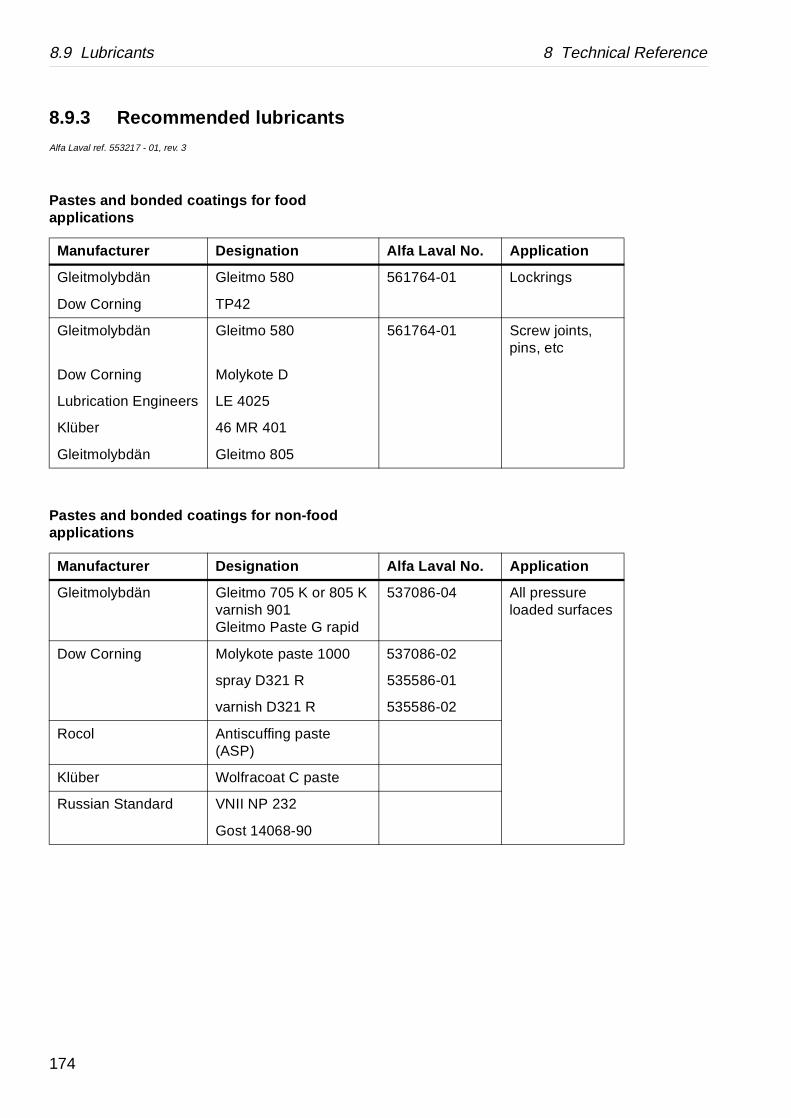
8.9 Lubricants 8 Technical Reference
lfa Laval No. Applic ation
561764-01 Lockrings
561764-01 Screw joints, pins, etc
lfa Laval No. Applic ation
537086-04 All pressure loaded surfaces
537086-02
535586-01
535586-02
8.9.3 Recommended lubricantsAlfa Laval ref. 553217 - 01, rev. 3
Pastes and bonded coatings for food applications
Pastes and bonded coatings for non-food applications
Manufacturer Designation A
Gleitmolybdän Gleitmo 580
Dow Corning TP42
Gleitmolybdän Gleitmo 580
Dow Corning Molykote D
Lubrication Engineers LE 4025
Klüber 46 MR 401
Gleitmolybdän Gleitmo 805
Manufacturer Designation A
Gleitmolybdän Gleitmo 705 K or 805 Kvarnish 901Gleitmo Paste G rapid
Dow Corning Molykote paste 1000
spray D321 R
varnish D321 R
Rocol Antiscuffing paste (ASP)
Klüber Wolfracoat C paste
Russian Standard VNII NP 232
Gost 14068-90
174
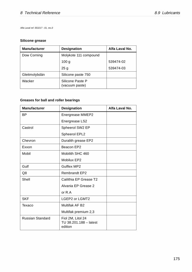
8 Technical Reference 8.9 Lubricants
Alfa Laval No.
539474-02
539474-03
Alfa Laval No.
Alfa Laval ref. 553217 - 01, rev.3
Silicone grease
Greases for ball and roller bearings
Manufacturer Designation
Dow Corning Molykote 111 compound
100 g
25 g
Gleitmolybdän Silicone paste 750
Wacker Silicone Paste P(vacuum paste)
Manufacturer Designation
BP Energrease MMEP2
Energrease LS2
Castrol Spheerol SW2 EP
Spheerol EPL2
Chevron Duralith grease EP2
Exxon Beacon EP2
Mobil Mobilith SHC 460
Mobilux EP2
Gulf Gulflex MP2
Q8 Rembrandt EP2
Shell Cailithia EP Grease T2
Alvania EP Grease 2
or R.A
SKF LGEP2 or LGMT2
Texaco Multifak AF B2
Multifak premium 2,3
Russian Standard Fiol 2M, Litol 24TU 38.201.188 – latest edition
175
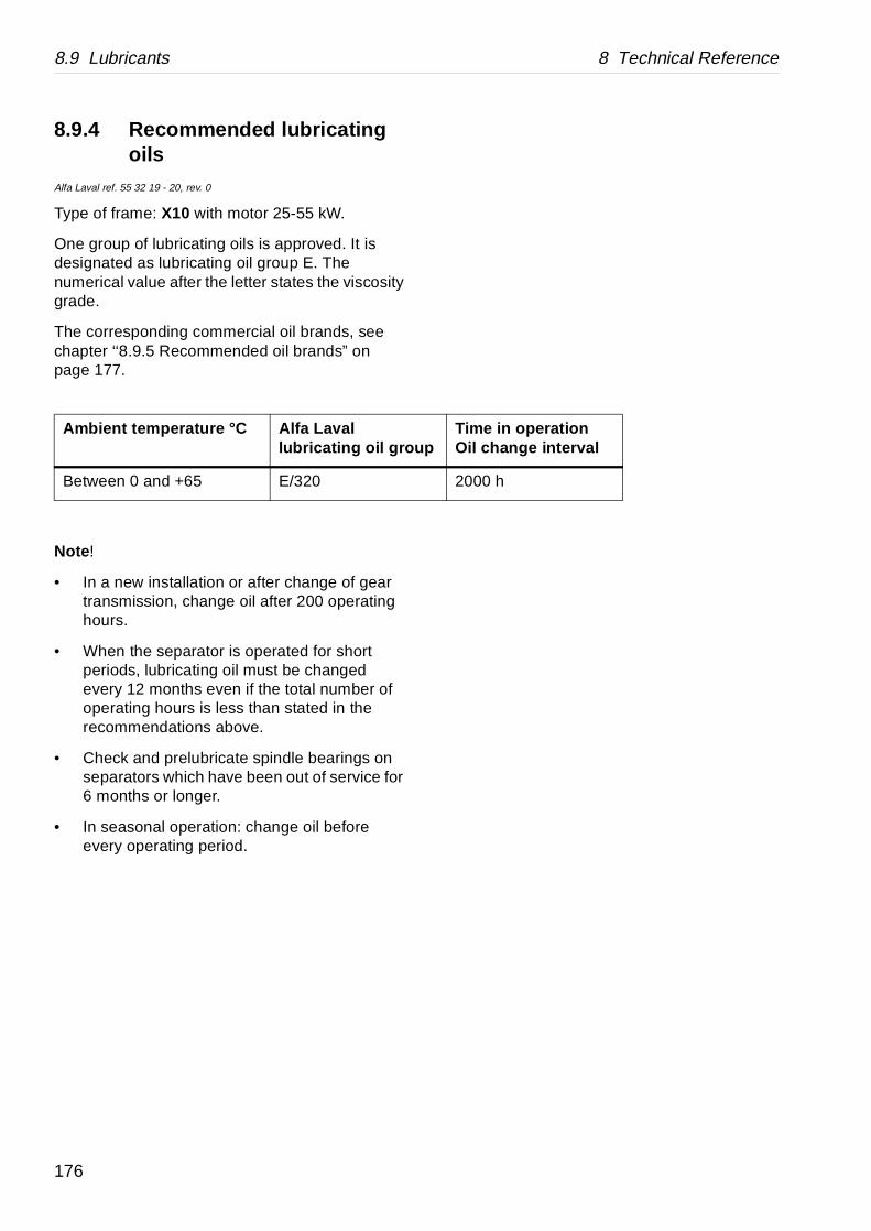
8.9 Lubricants 8 Technical Reference
Time in operationOil change interval
2000 h
8.9.4 Recommended lubricating oils
Alfa Laval ref. 55 32 19 - 20, rev. 0
Type of frame: X10 with motor 25-55 kW.
One group of lubricating oils is approved. It is designated as lubricating oil group E. The numerical value after the letter states the viscosity grade.
The corresponding commercial oil brands, see chapter ‘‘8.9.5 Recommended oil brands” on page 177.
Note !
• In a new installation or after change of gear transmission, change oil after 200 operating hours.
• When the separator is operated for short periods, lubricating oil must be changed every 12 months even if the total number of operating hours is less than stated in the recommendations above.
• Check and prelubricate spindle bearings on separators which have been out of service for 6 months or longer.
• In seasonal operation: change oil before every operating period.
Ambient temperature °C Alfa Laval lubricating oil group
Between 0 and +65 E/320
176

8 Technical Reference 8.9 Lubricants
oup E
n
1 (4 litres)
8.9.5 Recommended oil brandsAlfa Laval ref. 55 32 18 - 14, rev 0
1) According to ISO 3448/31042) According to ISO 2909
Alfa Laval Lubricating oil gr
Viscosity grade VG1) 320
Viscosity index VI2) > 92
Supplier Designatio
Alfa Laval 558129-0
177

8.10 Other drawings 8 Technical Reference
G0
8600
11
8.10 Other drawings
8.10.1 Foundation drawingAlfa Laval ref. 561682, rev. 0
178

8 Technical Reference 8.10 Other drawings
Recommended free floor space for unloading when doing service
No fixed installation within this area)
Vertical force not exceeding 34 kN/foot*
Horizontal force not exceeding 34 kN/foot*
Total static load max. 22 kN
* For guidance only. Based on estimates and unverified calculations.
A. Min.lifting capacity required when doing service 1700 kg
B. Max. height of largest component incl. lifting toolRecommended speed for lifting:Low speed 0,5-1,5 m/minHigh speed 2-6 m/min
C. Center of motorD. Center of separator bowlE. 24 holes ∅ 12 for anchorage.F. Horizontal max. deviation 0,4°G. Installation according to stated foundation forcesH. Floor levelI. Structural concreteJ. Anchor boltsK. Service side
179

8.10 Other drawings 8 Technical Reference
star-delta starting
G0
787
911
8.10.2 Electric motorAlfa Laval ref. 551827, rev. 2
Type of mounting(IEC 34-7)
Degree of protection(IEC34-5)
IM 1001 IP 55
Manufacturer ABB Motors AB
Manufacturers drawing HXUR 1 SE 87-05
Standards IEC 34-1, IEC 72
Size 250 M
Type HXR250MB 4 B3
Weight 410 kg
Poles 4
Insulation class F
Bearings DE 6315/C3, NDE 6313/C3
Method of cooling IC 41 (IEC 34-6)
Specification Totally enclosed CT-motor for
A. Shaft dimensionsB. Turnable terminal box
180

8 Technical Reference 8.10 Other drawings
urrentA
Pow.fac cos ϕ ϕ
|st / | 1) Therm 2) °C
Note
102 0,88 1,5 190
93 0,86 1,7 190
176 0,88 1,5 190
88 0,88 1,5 190
78 0,88 1,5 190
59 0,88 1,5 190
194 0,88 1,5 190
17688
0,88 1,7 190 D-parD-ser
168 84
0,87 1,9 190 D-parD-ser
67 0,88 1,7 CSA-plated
102 0,88 1,7 190
88 0,88 1,7 190
176 0,88 1,7 190
84 0,87 1,9 190
168 0,87 1,9 190
81 0,87 1,9 190
97 0,88 1,5 190
56 0,88 1,5 190
1) lst /l= starting current /rated current at star-delta starting.
2) Thermistors tripping temperature.3) Separate terminal box for thermistors,
variants -08 and -09 only.
Article No OutputkW
Speed RPM
FreqHz
Voltage V
C
551827-01 55 1467 50 380 D
551827-02 55 1472 50 415 D
551827-03 55 1467 50 220 D
551827-04 55 1467 50 440 D
551827-05 55 1467 50 500 D
551827-06 55 1467 50 660 D
551827-07 55 1467 50 200 D
551827-08 3) 55 1772 60 220 D440 D
551827-09 3) 55 1774 60 230 D460 D
551827-10 55 1772 60 575 D
551827-11 55 1772 60 380 D
551827-12 55 1772 60 440 D
551827-13 55 1772 60 220 D
551827-14 55 1772 60 460 D
551827-15 55 1772 60 230 D
551827-16 55 1772 60 480 D
551827-17 55 1467 50 400 D
551827-18 55 1467 50 690 D
181
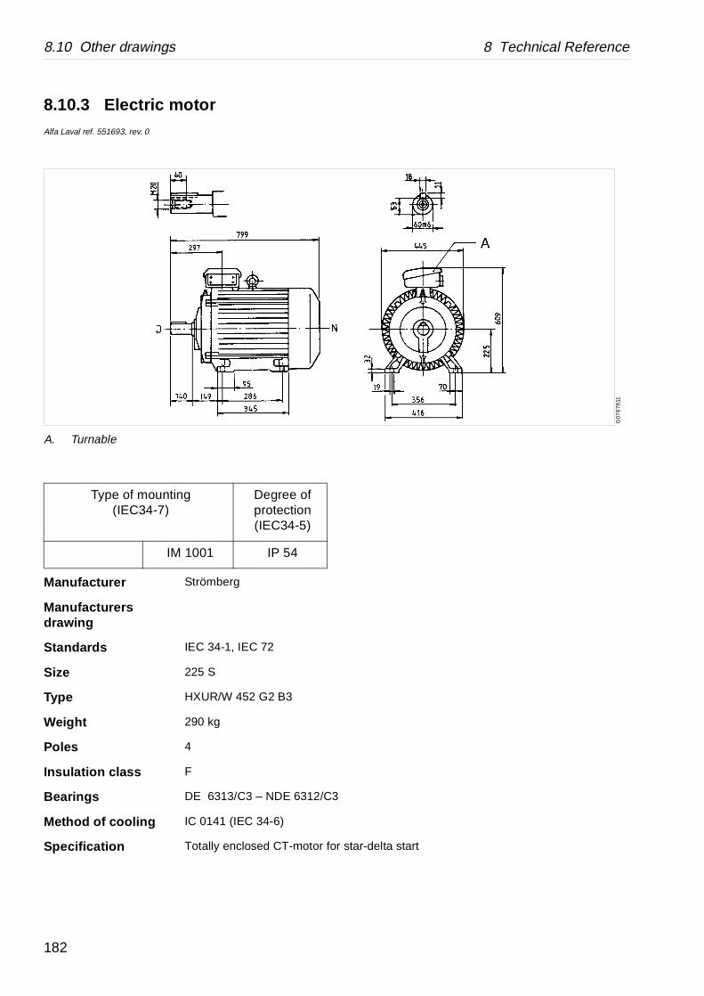
8.10 Other drawings 8 Technical Reference
star-delta start
G07
878
11
8.10.3 Electric motorAlfa Laval ref. 551693, rev. 0
Type of mounting(IEC34-7)
Degree of protection(IEC34-5)
IM 1001 IP 54
Manufacturer Strömberg
Manufacturers drawing
Standards IEC 34-1, IEC 72
Size 225 S
Type HXUR/W 452 G2 B3
Weight 290 kg
Poles 4
Insulation class F
Bearings DE 6313/C3 – NDE 6312/C3
Method of cooling IC 0141 (IEC 34-6)
Specification Totally enclosed CT-motor for
A. Turnable
182
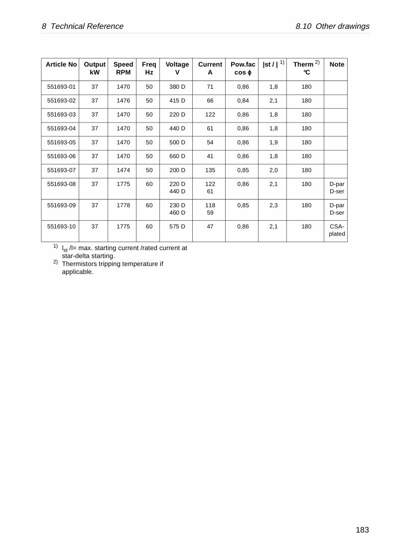
8 Technical Reference 8.10 Other drawings
rrentA
Pow.fac cos ϕ ϕ
|st / | 1) Therm 2) °C
Note
71 0,86 1,8 180
66 0,84 2,1 180
22 0,86 1,8 180
61 0,86 1,8 180
54 0,86 1,9 180
41 0,86 1,8 180
35 0,85 2,0 180
2261
0,86 2,1 180 D-parD-ser
1859
0,85 2,3 180 D-parD-ser
47 0,86 2,1 180 CSA-plated
1) lst /l= max. starting current /rated current at star-delta starting.
2) Thermistors tripping temperature ifapplicable.
Article No OutputkW
Speed RPM
FreqHz
Voltage V
Cu
551693-01 37 1470 50 380 D
551693-02 37 1476 50 415 D
551693-03 37 1470 50 220 D 1
551693-04 37 1470 50 440 D
551693-05 37 1470 50 500 D
551693-06 37 1470 50 660 D
551693-07 37 1474 50 200 D 1
551693-08 37 1775 60 220 D440 D
1
551693-09 37 1778 60 230 D460 D
1
551693-10 37 1775 60 575 D
183

8.10 Other drawings 8 Technical Reference
G07
8761
1
8.10.4 Motor drive dataAlfa Laval ref. 55 17 76
_________________ Measured
__ __ __ __ __ __ __ Calculated
A. Speed (r/min)B. Current (amp.)C. Motor speed 60 HzD. Motor speed 50 HzE. Time (minutes)F. amp.
kW(input)G. kW (output)
184

8 Technical Reference 8.10 Other drawings
r data sheet.
higher.
r/min 50 Hz
r/min 60 Hz
ηη cos ϕ ϕ Ms (Y)
1470 1775 92%
0,86 110 Nm
Motor data at 380V 50 Hz according to Strömberg moto
Min. cable area: See also local codes.
η and cos ϕ valid for 50 Hz. Values for 60 Hz about 0,5%
Idling power input=6 kW.
Moment of inertia 12,95 kgm2 (bowl spindle)
Bowl speed max. 4805 rpm. motor 1500 or 1800 rpm.
Motor AL-No.
kW Manufact. Type No. of poles
551693 37 Strömberg HXUR/W 452 G2 4
U (V) I (A) Fuse (A)
Cable mm2
min. Cu
Cable mm 2
min. Al
380/50 71 80 35 50
415/50 65 80 35 50
500/50 54 63 25 35
440/60 61 80 35 50
575/60 47 63 25 35
220/50 122 160 95 120
185

8.11 Machine plates and safety labels 8 Technical Reference
G08
7501
1
8.11 Machine plates and safety labels
Alfa Laval ref. 561678, rev. 0
186
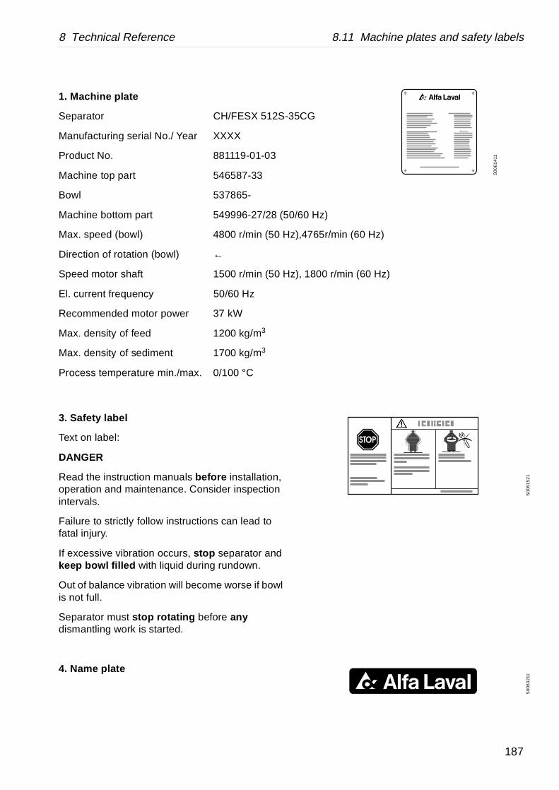
8 Technical Reference 8.11 Machine plates and safety labels
5CG
/60 Hz)
),4765r/min (60 Hz)
), 1800 r/min (60 Hz)
S0
061
411
S0
0615
21
S00
6321
1
3. Safety label
Text on label:
DANGER
Read the instruction manuals before installation, operation and maintenance. Consider inspection intervals.
Failure to strictly follow instructions can lead to fatal injury.
If excessive vibration occurs, stop separator and keep bowl filled with liquid during rundown.
Out of balance vibration will become worse if bowl is not full.
Separator must stop rotating before any dismantling work is started.
4. Name plate
1. Machine plate
Separator CH/FESX 512S-3
Manufacturing serial No./ Year XXXX
Product No. 881119-01-03
Machine top part 546587-33
Bowl 537865-
Machine bottom part 549996-27/28 (50
Max. speed (bowl) 4800 r/min (50 Hz
Direction of rotation (bowl) ←
Speed motor shaft 1500 r/min (50 Hz
El. current frequency 50/60 Hz
Recommended motor power 37 kW
Max. density of feed 1200 kg/m3
Max. density of sediment 1700 kg/m3
Process temperature min./max. 0/100 °C
187
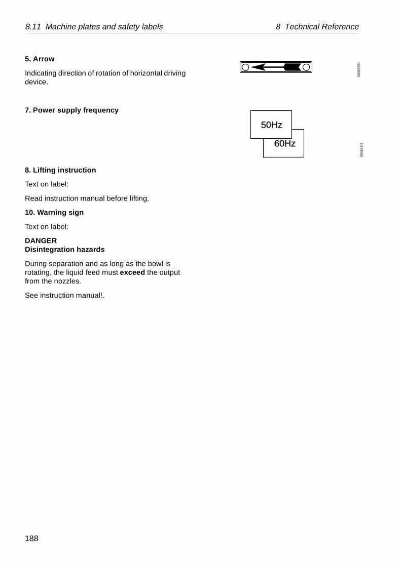
8.11 Machine plates and safety labels 8 Technical Reference
S00
6882
1
50Hz
60Hz
S00
6311
1
5. Arrow
Indicating direction of rotation of horizontal driving device.
7. Power supply frequency
8. Lifting instruction
Text on label:
Read instruction manual before lifting.
10. Warning sign
Text on label:
DANGERDisintegration hazards
During separation and as long as the bowl is rotating, the liquid feed must exceed the output from the nozzles.
See instruction manual!.
188
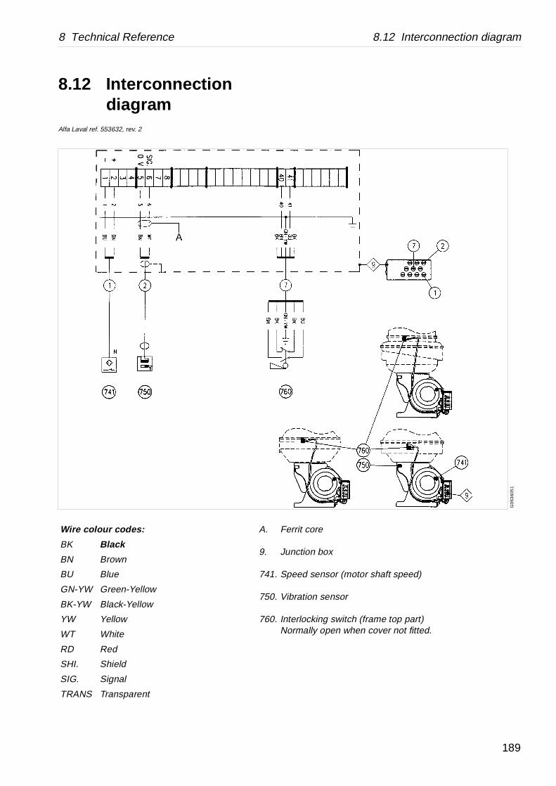
8 Technical Reference 8.12 Interconnection diagram
rit core
ction box
ed sensor (motor shaft speed)
ration sensor
rlocking switch (frame top part)rmally open when cover not fitted.
G0
6360
51
8.12 Interconnection diagram
Alfa Laval ref. 553632, rev. 2
Wire colour codes: A. Fer
9. Jun
741. Spe
750. Vib
760. InteNo
BK Black
BN Brown
BU Blue
GN-YW Green-Yellow
BK-YW Black-Yellow
YW Yellow
WT White
RD Red
SHI. Shield
SIG. Signal
TRANS Transparent
189
8.13 Storage and installation 8 Technical Reference
8.13 Storage and installation
8.13.1 Introduction
Most of the installation instructions are Specifications, which are compulsory requirements. These specifications are sometimes completed with non-compulsory Recommendations, which could improve the installation quality.
Additional installation information, such as drawings, connection lists and interface description, can be found previous in this chapter.
8.13.2 Storage and transport of goods
Storage
Specification
Upon arrival to the store, check all components and keep them:
1. Well stored and protected from mechanical damage and theft.
2. Dry and protected from rain and humidity.
3. Organized in the store in such a way that the goods will be easily accessible when installation is about to take place.
190
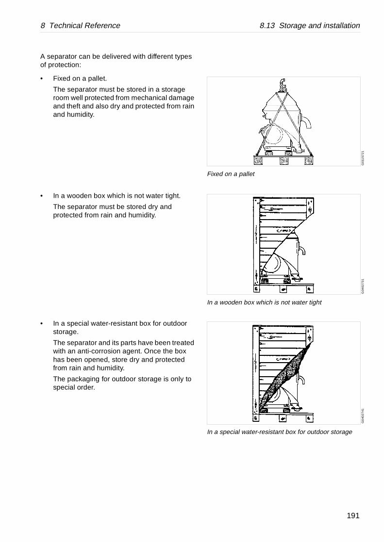
8 Technical Reference 8.13 Storage and installation
G01
157
21
Fixed on a pallet
G04
0273
1
In a wooden box which is not water tight
G0
4027
41
In a special water-resistant box for outdoor storage
A separator can be delivered with different types of protection:
• Fixed on a pallet.
The separator must be stored in a storage room well protected from mechanical damage and theft and also dry and protected from rain and humidity.
• In a wooden box which is not water tight.
The separator must be stored dry and protected from rain and humidity.
• In a special water-resistant box for outdoor storage.
The separator and its parts have been treated with an anti-corrosion agent. Once the box has been opened, store dry and protected from rain and humidity.
The packaging for outdoor storage is only to special order.
191

8.13 Storage and installation 8 Technical Reference
G0
020
611
Check the drawings when planning the installation
Transport
Specification
• During transport of the separator, the bowl must always be removed from the machine.
• When lifting a separator it must always be hung securely . See chapter ‘‘5.5 Lifting instructions” on page 66.
• During erection, all inlets and outlets to separators and accessories must be covered to be protected from dirt and dust.
8.13.3 Planning of installation
Introduction
The space required for one or more separators can be calculated by consulting the drawings in the chapters ‘‘8.2 Basic size drawing” on page 156, ‘‘8.10.1 Foundation drawing” on page 178 and instructions for ancillary equipment, electrical and electronic equipment and cables.
WARNING
Crush hazards
Use correct lifting tools and follow lifting instructions.
192
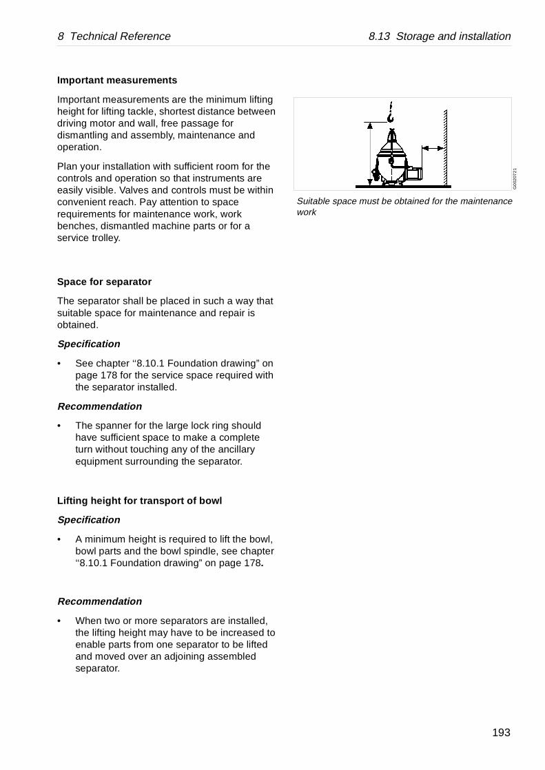
8 Technical Reference 8.13 Storage and installation
G0
0207
21
Suitable space must be obtained for the maintenance work
Important measurements
Important measurements are the minimum lifting height for lifting tackle, shortest distance between driving motor and wall, free passage for dismantling and assembly, maintenance and operation.
Plan your installation with sufficient room for the controls and operation so that instruments are easily visible. Valves and controls must be within convenient reach. Pay attention to space requirements for maintenance work, work benches, dismantled machine parts or for a service trolley.
Space for separator
The separator shall be placed in such a way that suitable space for maintenance and repair is obtained.
Specification
• See chapter ‘‘8.10.1 Foundation drawing” on page 178 for the service space required with the separator installed.
Recommendation
• The spanner for the large lock ring should have sufficient space to make a complete turn without touching any of the ancillary equipment surrounding the separator.
Lifting height for transport of bowl
Specification
• A minimum height is required to lift the bowl, bowl parts and the bowl spindle, see chapter ‘‘8.10.1 Foundation drawing” on page 178.
Recommendation
• When two or more separators are installed, the lifting height may have to be increased to enable parts from one separator to be lifted and moved over an adjoining assembled separator.
193

8.13 Storage and installation 8 Technical Reference
G04
8421
1
Place the separator in such a way that makes the oil change easy
Space for oil changing
Specification
The plug for gearbox oil draining must not be blocked by floor plate arrangement, etc.
Recommendation
• It should be possible to place a portable collecting tray under the gearbox drain plug for changing oil.
8.13.4 Foundations
Specification
• The separator should be installed at floor level, see chapter ‘‘8.10.1 Foundation drawing” on page 178.
• The separator must be installed on a strong and rigid foundation to reduce the influence of vibrations from adjacent machinery.
• Fit the separator frame as follows (see also ‘‘6.9 Frame feet” on page 143):
a. Fit the frame feet without adjusting washers to the frame.
b. Place the separator in its position.c. Mark out on the foundation positions for
screw holes for the anchoring bolts.d. Remove the separator and drill the holes.
WARNING
Crush hazard
Use correct lifting tools and follow lifting instructions. See ‘‘5.5 Lifting instructions” on page 66.
Do not work under hanging load.
194

8 Technical Reference 8.13 Storage and installation
e. Mount the anchoringt bolts on the foundation.
f. Lift the separator over the anchoring bolts.
g. Check horizontal alignment of the foundation plate. I necessary, add adjusting washers to get the frame horizontal.
h. Fit the bowl.
8.13.5 Preparations before first start
Technical demands for connections and logical limitations for the separator can be found in this chapter:
• Technical data
• Connection list
• Interface description
• Basic size drawing
• Foundation drawing.
Before first start the following shall be checked:
1. Ensure that pipes and drains have been flushed clean. If not, flush the pipe system. Open valves and flush the pipe system to remove any chips, welding beads etc. left from installation. Check that drains are not blocked.
2. Check that safety water system has been installed.
3. Check all pipes and electrical connections.
4. Install the separator and ensure that the separator is installed correctly.
DANGER
Disintegration hazard
When power cables have been connected, always check direction of rotation. If incorrect, vital rotating parts could unscrew causing disintegration of the machine.
195

8.13 Storage and installation 8 Technical Reference
196

e manuals as possible. Should you have any ual, please note them down and send them to g it by fax, or you could mail it, or hand it over
SKL, S-147 80 Tumba, Sweden.
Company:
City:
Book No.: 1271013-02 V2
Yes No
e table of contents?
quate?
your purposes?
s?
al?
Reader’s Comment Form
Dear reader,
It is our ambition to produce as useful and instructivcomments (positive or negative) regarding this manus. You can do this by copying this page and sendinto your local Alfa Laval representative.
Alfa Laval Separation AB, Separator Manuals, dept.Fax: +46 8 53065029.
Your name:
Address:
Country:
Product: CH/FESX 512S-35CG
Date:
Is it easy to find what you are looking for by using th
Are the chapter and section headings clear and ade
Is the information presented in the correct order for
Does the information in the manual cover your need
Is it easy to understand the instructions in the manu
Is the terminology sufficiently explained?
Are the illustrations easy to understand?
Your comments:
197

198

se copy this page and give it to your local rent prices.
to help you with information regarding any
Company:
City:
Book No.: 1271013-02 V2
Date:
Order Form
If you wish to order extra copies of this manual, pleaAlfa Laval representative, who will advise you of cur
Your local Alfa Laval representative will also be ableother manuals.
Your name:
Address:
Country:
Product: CH/FESX 512S-35CG
Quantity:
Comments:
199

200


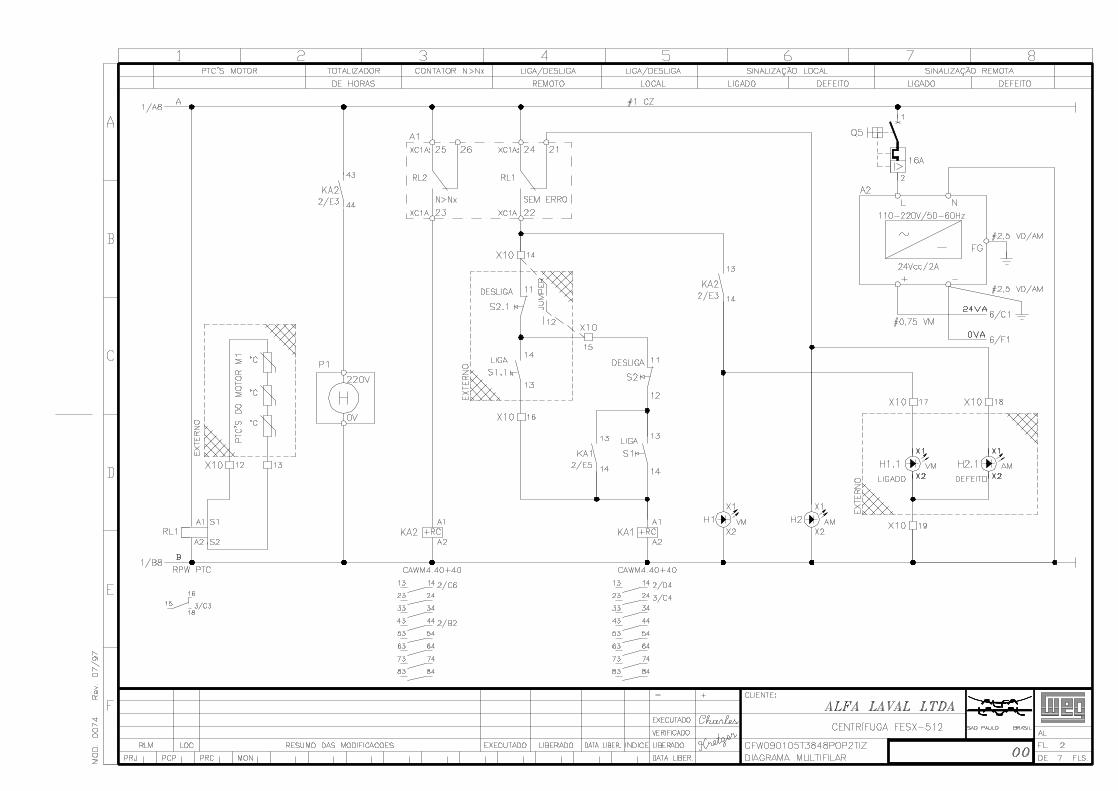
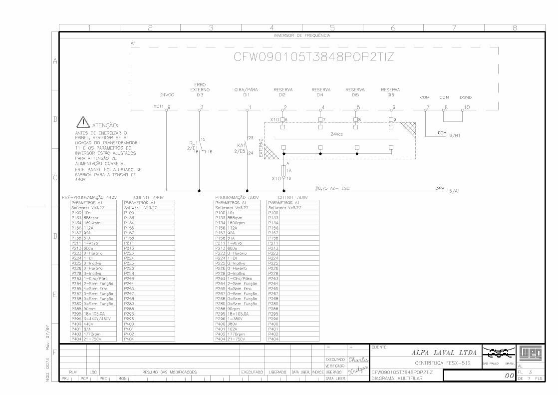

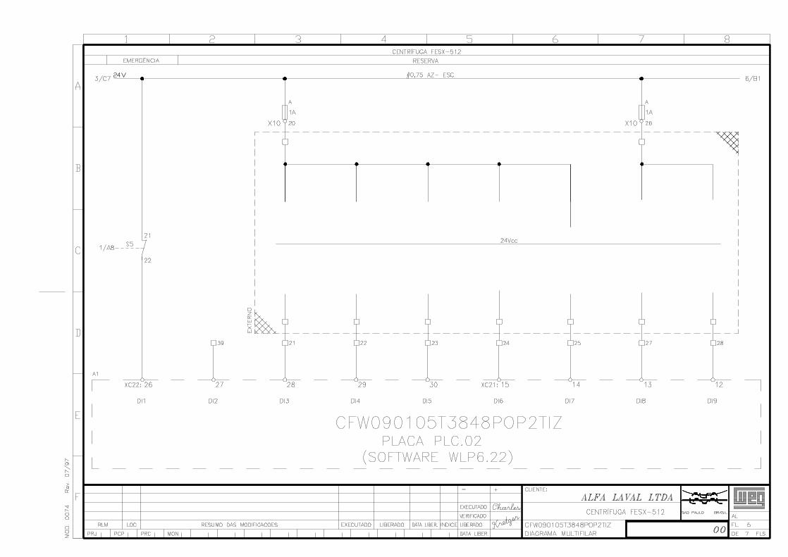
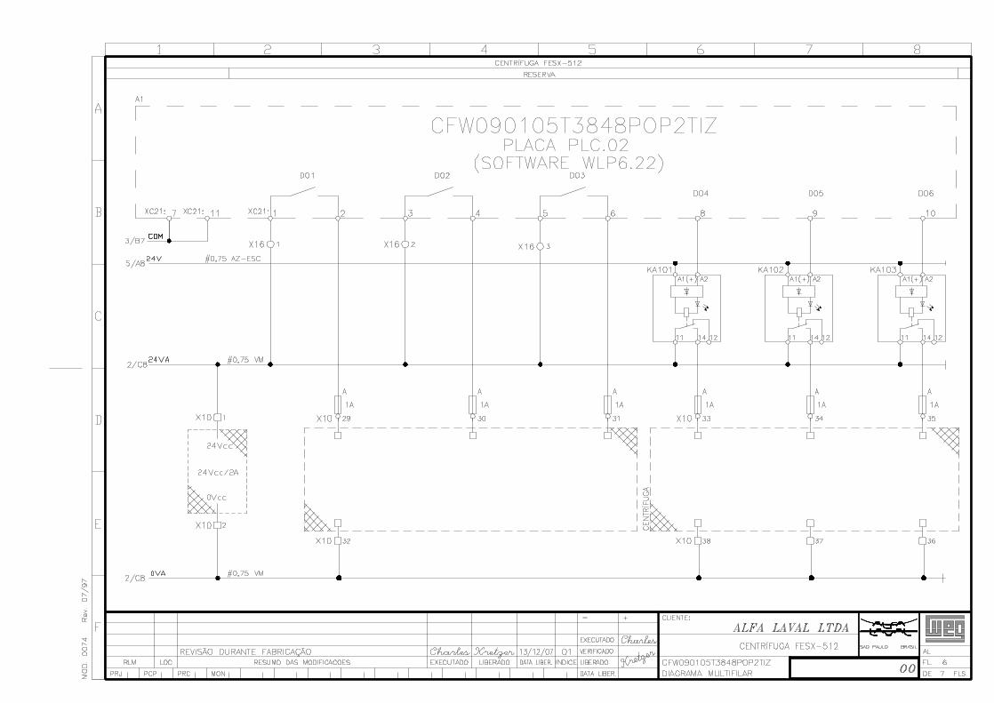

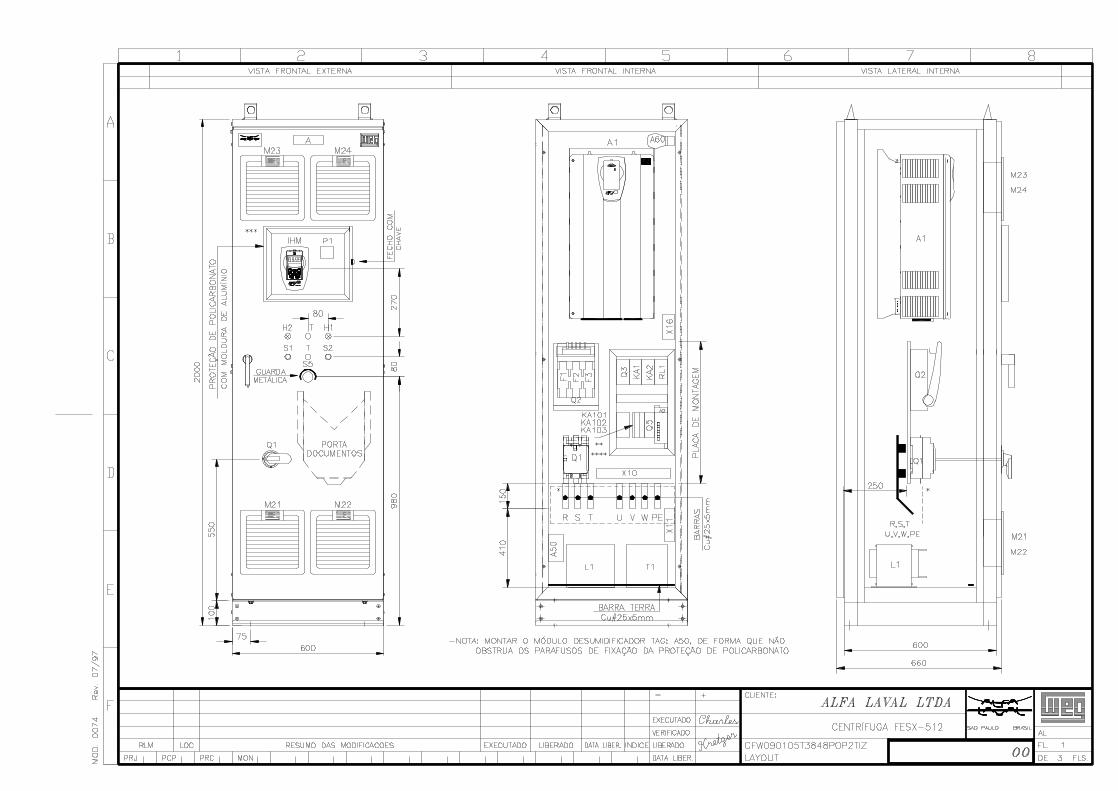

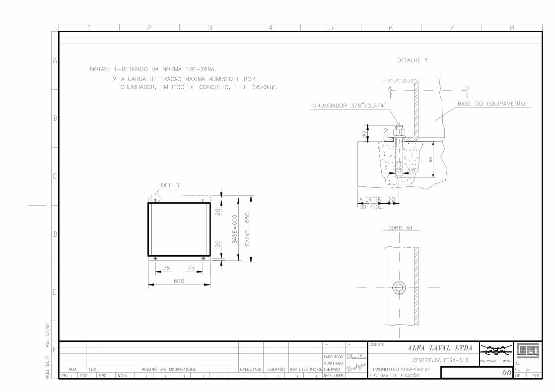
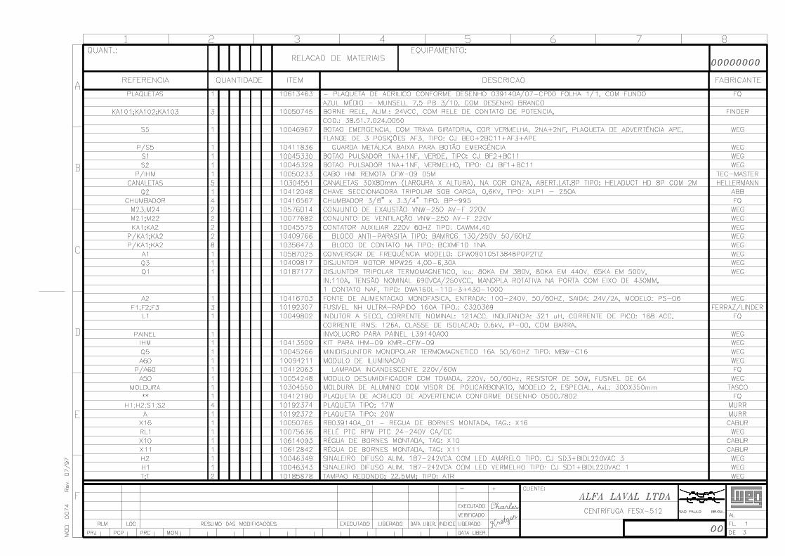


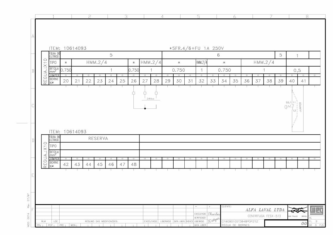

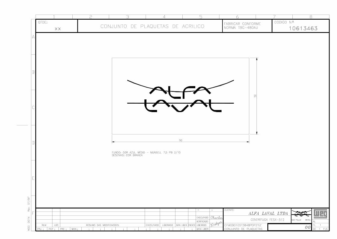
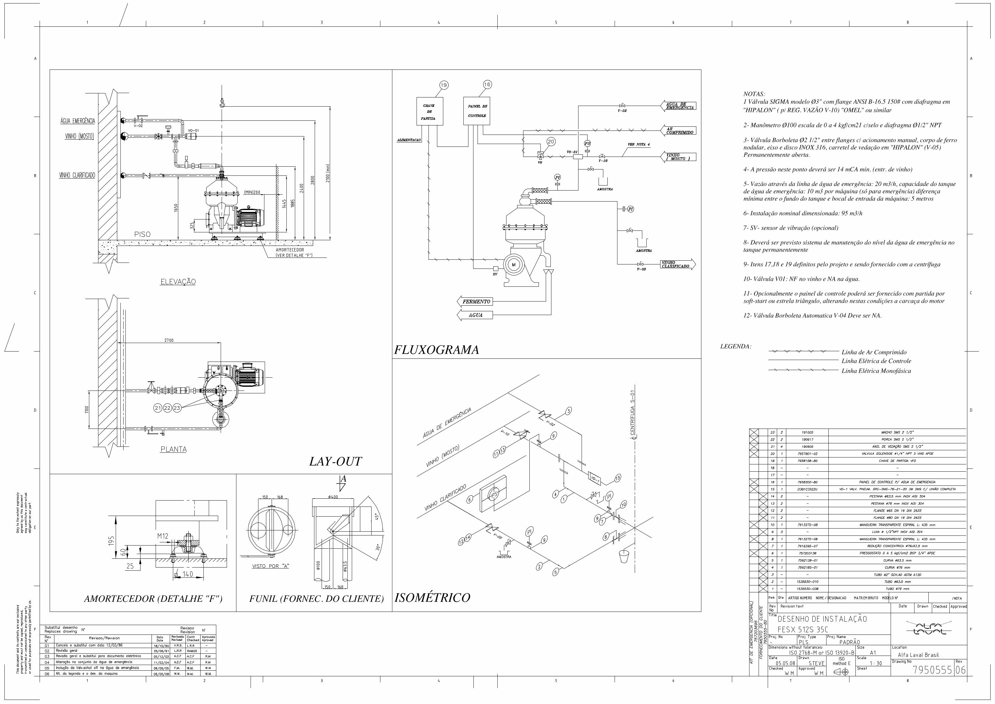
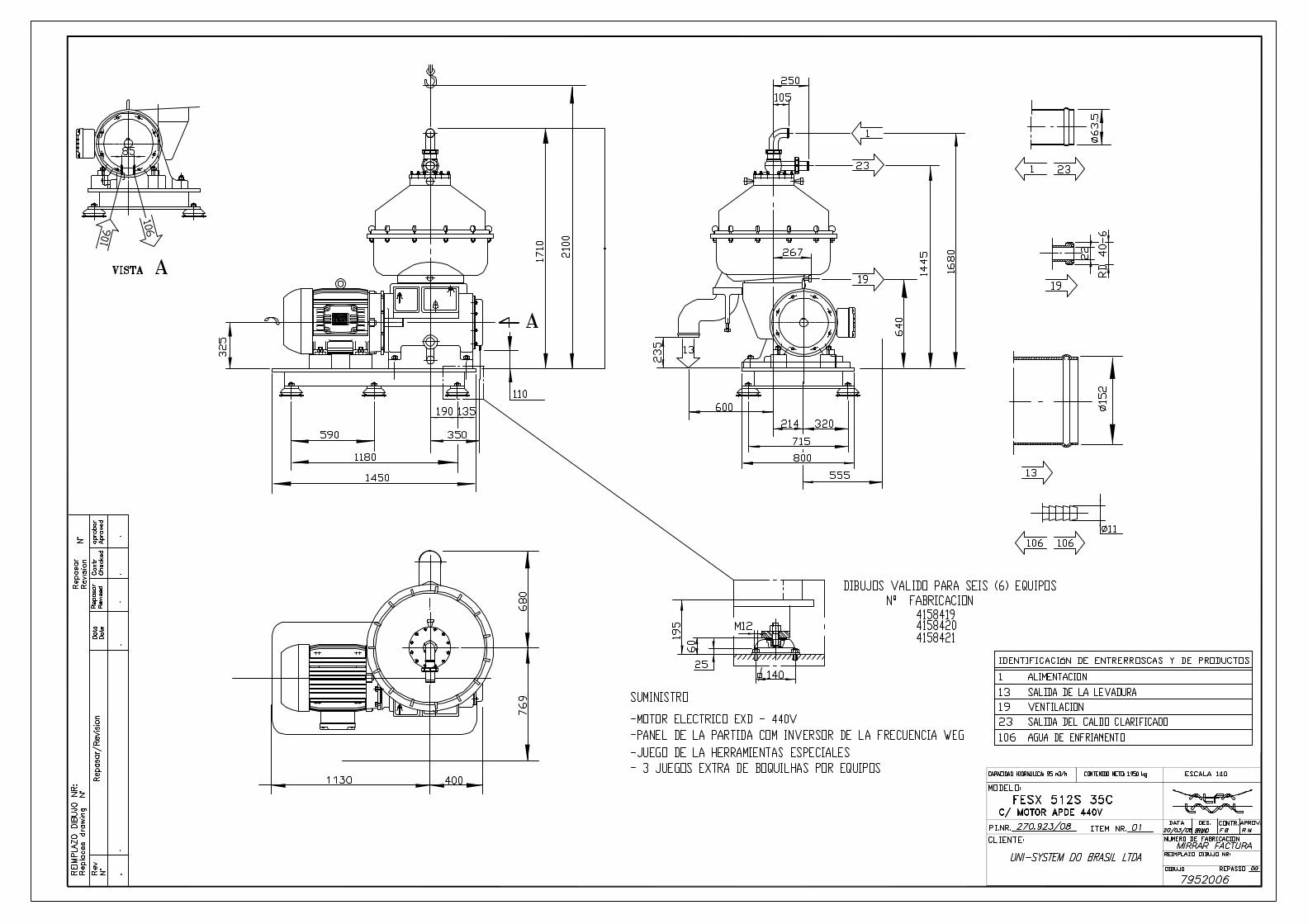

Tensão (V) Frequência (HZ) R.P.M. Isolam. Prot.
220/380/440 60 1775 H IP55
3,3 5,9 1,2 2,5 0,5 1,8
4,1 4,2 2,7 2,1 0,6 1,7
4,5 5,8 2,5 1,9 0,6 1,8
Inicial
Final
Data:
Data:
DISTRIBUIDOR A. PEQUENO
R3513
------------
Horímetro
2,8
MAX________ mm/s (RMS mm/seg)
Equipamento novo SIM Equipamento reformado/conserto
Pontos 1
Após giro de 90º no rotor (com
produto)4,1 6,4
Contra - Pressão (bar) Rotação do Motor (rpm)
PARTIDA DO EQUIPAMENTO ATRAVES DE:
2,3
Painel de Teste (inversor ou direta)
X
Tempo de partida (seg)
CERTIFICADO DE TESTE DE CENTRIFUGAS
2 3 4
54,8150
Contagiro (rpm)
Após 120 minutos (termino)
0,6
Tipo de óleo utilizadoTempo Parada c/ Freio (seg)
Corrente (A)
2,2
Fabricante do painel:
Inversor
Soft - starter
Estrela/Triângulo
Vazão (m³/h)
Painel da separadora (somente para transformação
ou novos)
APÓS TESTE
PINHÃO COROA ESTRUTURA
R3749
RG ou matricula
Nome:Teste realizado por: Inspetor Cliente
R3681 SR214
Responsável /Setor
AZW0805AVW.10993 - - AGW 3437
6
PRODUÇÃO
1775
WEG 225 S/M
Marca
Após a partida
Plano 2
Tensão (V)
440
Observações:
Massa (g) Massa (g)
Plano 1
Balanceamento realizado por:
DESEMPENHO E PERFORMANCE
Após 60 minutos (com produto)
Rotor completo Ângulo Ângulo
BALANCEAMENTO
Sist. Freio
-------------------- --------- ------ --------- ------- -------
5
Tipo
*BOMBA
55(75) 1003651049 176/102/88
Potência (cv) Nº Série Frequência (HZ)Tensão (V) Corrente (A)
51,5Alt. Eixo Rotor Alt. Rotor
------------Alt. Disco Imp.Desc Diam. Disco Grav
MOTORMarca Tipo Corrente (A)Potência (cv) Nº Série
-----------Diam Anel Nível
------------
Data: 12-03-09
Nº de Série:4158420
Cliente: UNI SYSTEMS
Montada como: Purificadora ? Concentradora ? Clarificadora ?
Modelo:FESX 712BX 35 C Nº P.I: 0270923N° da MO: 0150400
EIXO VERTICAL
MONTAGEM
Montagem realizada por:
Nº DE CORRIDA
Coroa
Pinhão
C. ROTOR -- TAMPA ROTOR A. FECHAMENTO
TAG-6001-BAplicação:
0,02Desvio Eixo RotorTemperatura (ºC)
AmbienteAGUATempo teste2 HORAS
Inspeção Visual
Teste Mecânico
Flanges Tubul.
Liq. Teste82
Nº discos
1
3
45
6
2
C:BRCORP/CERTIFICADOS DE TESTES/CENTRIFUGAS/CERTIFICADO DE TESTE PADRAO VERSÃO 05/12/2008