data documentation - diw€¦ · based on giignl min, avg, max 1.15-1.27-1.39. we process lng data...
TRANSCRIPT

Data Documentation
Global Gas ModelModel and Data Documentation v3.0 (2019)
Ruud Egging and Franziska Holz
100
Deutsches Institut für Wirtschaftsforschung 2019

IMPRESSUM © DIW Berlin, 2019DIW Berlin Deutsches Institut für Wirtschaftsforschung Mohrenstr. 58 10117 Berlin Tel. +49 (30) 897 89-0 Fax +49 (30) 897 89-200 www.diw.de ISSN 1861-1532 All rights reserved. Reproduction and distribution in any form, also in parts, requires the express written permission of DIW Berlin.

Data Documentation 100
Ruud Egging*
Franziska Holz**
Global Gas Model
Model and Data Documentation v3.0 (2019)
EU Horizon 2020 Research Project
“SET-Nav – Navigating the Roadmap for Clean, Secure and Efficient EnergyInnovation” (Grant agreement No 691843)
Berlin, May 3rd 2019
* Department of Industrial Economics and Technology Management (IØT), Norwegian University of Scienceand Technology (NTNU), Trondheim, Norway and DIW Berlin, Department Energy, TransportationEnvironment, Berlin, Germany.
** DIW Berlin, Department Energy, Transportation, Environment, Berlin, Germany, and Norwegian Universityof Science and Technology (NTNU), NTNU Energy Transition Initiative (NETI), Trondheim, Norway.

Global Gas ModelModel and Data Documentation v3.0 (2019)
Ruud Egging ab, Franziska Holz ab,
With support by Victoria Czempinski bc, Alexandra Lüth ac, Sebastian Wegel bc, Jan Zepter ac
a Department of Industrial Economics and Technology Management (IØT), NTNU Trondheimb German Institute for Economic Research (DIW Berlin)
c Working Group for Infrastructure Policy (WIP), Technical University Berlin (TUB)
April 2019
https://www.ntnu.edu/web/iot/ggm
License:
This work is licensed under the MIT License (MIT).
Copyright (c) 2019 Ruud Egging (NTNU), Franziska Holz (DIW Berlin)
Permission is hereby granted, free of charge, to any person obtaining a copy of this software and associateddocumentation files (the "Software"), to deal in the Software without restriction, including without limitationthe rights to use, copy, modify, merge, publish, distribute, sublicense, and/or sell copies of the Software, and topermit persons to whom the Software is furnished to do so, subject to the following conditions:
The above copyright notice and this permission notice shall be included in all copies or substantial portions ofthe Software.
The software is provided "as is", without warranty of any kind, express or implied, including but not limited tothe warranties of merchantability, fitness for a particular purpose and noninfringement. in no event shall theauthors or copyright holders be liable for any claim, damages or other liability, whether in an action ofcontract, tort or otherwise, arising from, out of or in connection with the software or the use or other dealingsin the software.

Data Documentation 100
Introduction
3
Table of contentsTable of contents 3
List of tables 5
Notation 7
1 Introduction 8
2 Model structure 8
3 File data.xlsx 11
3.1 Data.xlsx - Sheet O – Other data 11
3.2 Data.xlsx – Sheet N – Nodes data 13
3.3 Data.xlsx – Sheet A - Arcs 14
3.4 Data.xlsx – Sheet V – LNG shipping distances 17
3.5 Data.xlsx – Sheet W - Storage 18
3.6 Data.xlsx– Sheet M - Market power 20
4 File data_proj.xlsx 22
4.1 Production and consumption data 22
5 Files data_calib.xlsx 26
5.1 Calibration 26
5.2 Reconciling value chain losses 27
5.3 Production calibration 27
5.4 Consumption calibration 28
6 Parameter value calculations 31
6.1 GAMS file in_prod.gms 31
6.2 GAMS file in_cons.gms 32
6.3 GAMS file in_arcs.gms 33
6.4 GAMS file in_stor.gms 34
6.5 GAMS file in_market.gms 34
7 References 35
8 Appendix A: How to Run GGM? 37
8.1 Version and license 37
8.2 GGM in short 37
8.3 Model structure 38
8.4 Folder structure 38
8.5 Model files 38
8.6 Model input 39
8.7 Model execution 39
8.8 Model output reports and suggested gdx layout 39
9 Appendix B: Mathematical Model Formulation 46

Data Documentation 100
Introduction
4
9.1 Notation and units of measurement 46
9.2 Supplier 48
9.3 Consumer surplus 48
9.4 Supplier market power 48
9.5 Market power adjustment term 49
9.6 Infrastructure restrictions 49
9.7 Optimization model 50
9.8 Objective 50
10 Appendix C: Pipeline characteristics 51
10.1 Pipeline investment costs 51
10.2 Operational costs and losses 52
10.3 Literature references for pipeline data 52
11 Appendix D: LNG value chain characteristics 53
11.1 Unit conversion and exchange rate 53
11.2 Liquefaction 54
11.3 Regasification 56
11.4 LNG Shipping 57
11.5 LNG value chain literature sources 60
12 Appendix E: Storage characteristics 61

Data Documentation 100
Introduction
5
List of tablesTable 1 Units of measurement 7Table 2 Range of energy content of natural gas 7Table 3 Gas market data categories 9Table 4 MS Excel workbooks with input data 10Table 5 sheets in data.xlsx 11Table 6 Data table in worksheet O 12Table 7: Summary of sources for model nodes, consumption and production data 13Table 8: Global regions represented in GGM 14Table 9 Summary of sources by scenario and data type 15Table 10: Data sources for pipelines 16Table 11: Data sources for liquefaction and regasification 17Table 12: Structure of the distance matrix for ports 17Table 13: Data structure and sources for gas storage data 18Table 14: Categories for different storage types 20Table 15: Categories for different storage types 21Table 16 Summary of production and consumption data sources 22Table 17: Sheets in workbook data_calib.xlsx 27Table 18: GlobLoss 27Table 19: PCapCalib 27Table 20: PCostCalib 28Table 21 Selected gas prices (Based on BP 2018, using conversion 38 MMbtu/cm) 29Table 22 GGM references prices 2015 selected countries 29Table 23 PriceCalib 30Table 24 Input parameters determined in in_prod.gms 31Table 25 Input parameters determined in in_cons.gms 32Table 26 Input parameters determined in in_arcs.gms 33Table 27 Input parameters determined in in_stor.gms 34Table 28 MS Excel workbooks with input data 39Table 29 Country mass balance 40Table 30 Nodal mass balance 40Table 31 Country calibration 41Table 32 Region calibration 41Table 33 Liquefaction infrastructure 43Table 34 Regasification infrastructure 44Table 35 Pipeline infrastructure 44Table 36 Storage infrastructure 44Table 37 Sets 46Table 38 Infrastructure Parameters 47Table 39 Market Parameters 47Table 40 Variables 47Table 41: Overview of pipeline data ranges 51Table 42: Exemplary data points for pipeline investment costs 51Table 43: Overview of operational pipeline cost data 52Table 44: Overview of pipeline loss data 52Table 45: Overview of LNG data ranges 53Table 46: Natural gas energy content: overview of literature estimates 53Table 47: Historical average exchange rates US-Dollar vs. Euro 54Table 48: Overview of LNG liquefaction investment costs in the literature 54Table 49: Overview of estimates of LNG liquefaction operational costs in the literature 55

Data Documentation 100
Introduction
6
Table 50: Overview of estimates of LNG liquefaction operational losses in the literature 56Table 51: Overview of LNG regasification investment cost estimates in the literature 56Table 52: Overview of estimates of regasification operational costs in the literature 56Table 53: Overview of loss rate estimates in the literature for LNG regasification 57Table 54: Overview of LNG shipping cost estimates in the literature 58Table 55 Shipping Rates ($/MBtu) 58Table 56: Distances for these LNG trade relations in the GGM database (in 1000 sea miles) 59Table 57: Calculated estimates for LNG shipping costs ($ / kcm / 1000 sea miles) 59Table 58: Overview of loss estimates of LNG shipping in the literature (boil off per 1000 sea miles) 59Table 59: Overview of storage data ranges 61
Data Documentation 100
Introduction
7
Notation
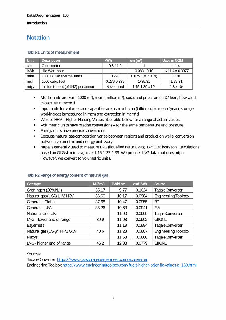
Table 1 Units of measurement
Unit Description kWh cm (m3) Used in GGMcm Cubic meter 9.8-11.9 1 11.4kWh kilo Watt hour 1 0.083 - 0.10 1/11.4 = 0.0877mbtu 1000 British thermal units 0.293 0.0257 (=1/38.9) 1/38mcf 1000 cubic feet 0.276-0.335 1/35.31 1/35.31mtpa million tonnes (of LNG) per annum Never used 1.15-1.39 x 10⁹ 1.3 x 10⁹
§ Model units are kcm (1000 m3), mcm (million m3), costs and prices are in € / kcm; flows andcapacities in mcm/d
§ Input units for volumes and capacities are bcm or bcma (billion cubic meter/year); storageworking gas is measured in mcm and extraction in mcm/d
§ We use HHV – Higher Heating Values. See table below for a range of actual values.§ Volumetric units have precise conversions – for the same temperature and pressure.§ Energy units have precise conversions§ Because natural gas composition varies between regions and production wells, conversion
between volumetric and energy units vary.§ mtpa is generally used to measure LNG (liquefied natural gas). BP: 1.36 bcm/ton; Calculations
based on GIIGNL min, avg, max 1.15-1.27-1.39. We process LNG data that uses mtpa.However, we convert to volumetric units.
Table 2 Range of energy content of natural gas
Gas type MJ/m3 kWh/cm cm/kWh Source
Groningen (20% N2!) 35.17 9.77 0.1024 Taqa eConverterNatural gas (USA) LHV/NCV 36.60 10.17 0.0984 Engineering ToolboxGeneral – Global 37.68 10.47 0.0955 BPGeneral – USA 38.26 10.63 0.0941 EIANational Grid UK 11.00 0.0909 Taqa eConverterLNG – lower end of range 39.9 11.08 0.0902 GIIGNLBayernets 11.19 0.0894 Taqa eConverterNatural gas (USA)* HHV/GCV 40.6 11.28 0.0887 Engineering ToolboxFluxys 11.63 0.0860 Taqa eConverterLNG - higher end of range 46.2 12.83 0.0779 GIIGNL
Sources:Taqa eConverter https://www.gasstoragebergermeer.com/econverterEngineering Toolbox https://www.engineeringtoolbox.com/fuels-higher-calorific-values-d_169.html

Data Documentation 100
Introduction
8
IntroductionThis report is part of the data documentation for the Global Gas Model (GGM) as prepared foranalyses in the H2020 SET-Nav project1 and subsequent studies. Since some data are proprietary wecannot make available all input data we have used. By describing input data, the processing steps,and the resulting input files we aim for maximum transparency and to allow anyone to reproduce thedata sets from scratch if desired.
GGM was developed by Egging (2010, 2013), also based on expertise gained in the development andapplication of the European Gas Model (Egging et al., 2008) and the World Gas Model (Egging et al.,2010, 2009). GGM was applied with various data sets and versions in studies of the future global(Holz et al., 2015) and European gas markets (Holz et al., 2016, 2017). In addition to the impact ofclimate policy, supply security has been a recurring concern (e.g. Richter and Holz, 2015). Moreover,a stochastic version that used a scenario tree was applied in Egging and Holz (2016). In the SET-Navproject, GGM contributed to the analyses of projects of common interest (PCI), their profitability andpublic support requirements (Kotek et al., 2018). This is a deterministic model version (i.e. noprobabilistic scenario tree).
If you find significant omissions or errors in this document, the GAMS code or the MS Excel files Iwould be grateful if you can send me an email at [email protected].
Model structureGGM is implemented in GAMS2. The deterministic GGM reads input from three MS Excel workbooks3,which is processed further in the model. The structure and contents of the MS Excel workbooks aredescribed in this document, as are the relevant assignments in GAMS processing these data. A briefdescription of the underlying data sources and processing steps is also given.
Figure 1 gives a schematic overview of the types of actors along the natural gas value chain that arerepresented in the Global Gas Model. For each actor, we use specific input data that is documentedin the following.
1 SET-Nav www.set-nav.eu (H2020 grant agreement no. 691843)2 GAMS www.gams.com3 The stochastic version reads scenario tree definitions from an extra workbook.

Data Documentation 100
Model structure
9
Storage
Prod
Supplier
Demandsectors
RegasifLiquef LNG ships
Storage
Demandsectors
Pipelines
Country A Country B
Prod
Figure 1: Actors and value chain represented in the Global Gas Model
Table 3 presents the main data categories relevant for natural gas market models. The actual inputdata are collected and formatted in three MS Excel workbooks (Table 4).
Table 3 Gas market data categories
Data category Abbrev Model parameters Input parametersProduction P Yearly capacities
Yearly costsReference production values, cost andother calibration parameters
Consumption C Seasonal intercept and slope ofdemand curves
Reference consumption values andprices, sector shares, seasonal loads,seasonal price adjustments
Pipelines Arcs: A – P Capacities, investment costs,operational costs, loss rates
Length, offshore part, initialcapacities, investment costs,operational costs, loss rates,maximum allowed expansions
Liquefactionterminals
Arcs: A – L Initial capacities, investment costs,operational costs, loss rates,maximum allowed expansionsRegasification
terminalsArcs: A – R
LNG ships Arcs: A – V Costs, losses Length of shipping routes, costs andlosses per distance unit
Storages W Working and extractioncapacities, investment andoperational costs, loss rates
Initial capacities, investment costs,operational costs, loss rates,maximum allowed expansions
Note: We use W for storages to clearly distinguish from S which is used for suppliers in other model versions.
This documentation provides the background information for data collected in the three Excel filesindicated in Table 4 below. For each workbook, the documentation starts with an overview on thestructure of the file and subsequently explains each sheet of the file. When deemed relevant, we giveactual data values and offer a brief explanation. Each workbook contains more information in theReadme-sheets. Additionally, in Section 0 we describe how the model parameters are calculatedbased on the input values read from the MS Excel workbooks. For internal process documentation
Data Documentation 100
Model structure
10
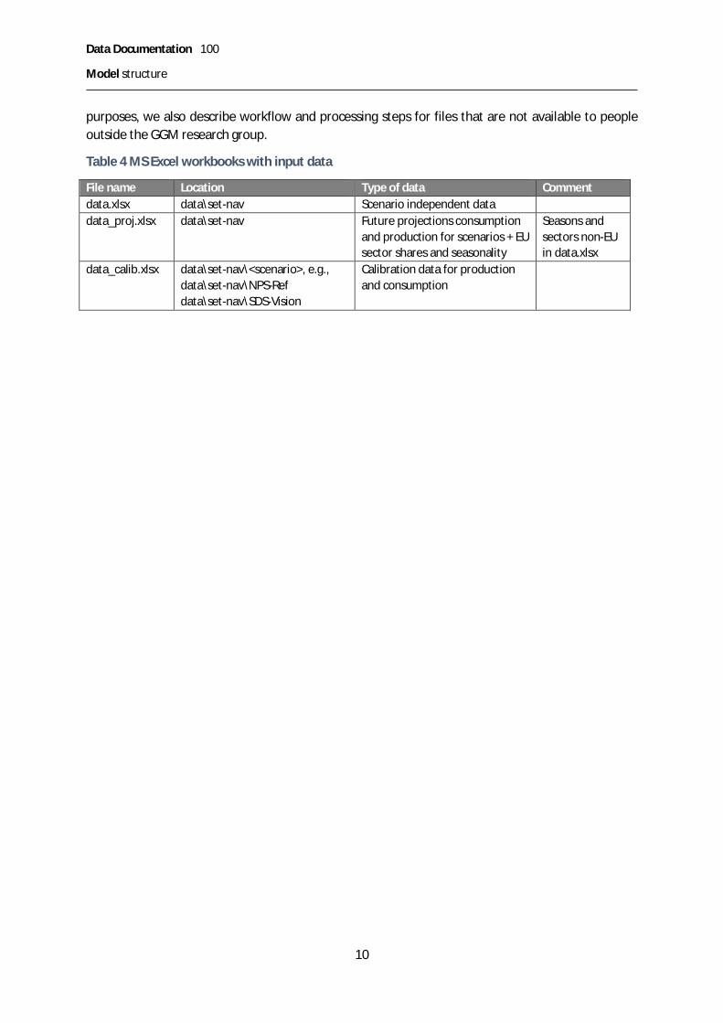
purposes, we also describe workflow and processing steps for files that are not available to peopleoutside the GGM research group.
Table 4 MS Excel workbooks with input data
File name Location Type of data Commentdata.xlsx data\set-nav Scenario independent datadata_proj.xlsx data\set-nav Future projections consumption
and production for scenarios + EUsector shares and seasonality
Seasons andsectors non-EUin data.xlsx
data_calib.xlsx data\set-nav\<scenario>, e.g.,data\set-nav\NPS-Refdata\set-nav\SDS-Vision
Calibration data for productionand consumption

Data Documentation 100
File data.xlsx
11
File data.xlsxThis section describes the first part dataset of the Global Gas Model, which is consolidated in the MSExcel file data.xlsx. The second part of the data is in sheet data_proj.xlsx and is presented in ChapterFile data_proj.xlsx.
The following sections discuss structure, data sources and processing steps for each sheet ofdata.xlsx. They also include some advice on how and where to modify the data, if necessary. Moredetail on the sources and the reasons for our specific data choices can be found in the Appendix(Sections 0-0). The file data.xlsx contains the following work sheets.
Table 5 sheets in data.xlsx
Sheet Information on CommentReadme This workbook Self explanatoryOther Parameters values Section 0N Geographical nodes; consumption seasonality and
sector shares for non-EUSection 0, seasons & sectors for EUnot here but in data_proj.xlsx
A pipelines, liquefaction and regasification terminals Section 0V distance matrix for shipping of LNG Section 0W gas storages Section 0M market power Section 0
Note that in MS Excel, the name manager shows definitions that are used by GAMS when reading theWorkbook:
Data.xlsx - Sheet O – Other dataThe sheet O (which stands for “Other data”) contains some set definitions and parameter values.
§ Production resources. = { , , }

Data Documentation 100
File data.xlsx
12
§ Storage types seasonal, LNG terminal, Peak. = { , , }§ Years used in the data sets = {2015,2020,2025, … ,2060}§ Seasons low, high and peak demand (EU perspective) = { , , }§ Sectors residential and commercial sector (building heating), industry, electric power
generation, transport = { , , , }
Here we present the entire table. Next, we indicate where values originate from.
Table 6 Data table in worksheet O
Parameter Value Unit DescriptionBFPipe 7 €/kcm/1000 km Operational tariff for using pipeline capacityBICPipe 109500 €/kcm/1000 km/ y Unit investment cost for onshore pipe capacityBLPipe 0.020 []/1000 km Pipeline loss fractionBIPipeOffshMult 2 [] Multiplication factor offshore pipe investment cost
BFLiq 20 €/kcm Operational tariff for using liquefaction capacityBFReg 10 €/kcm Operational tariff for using regasification capacityBFShip 8 €/kcm/1000 sea miles Operational tariff for using shipping capacityBICLiq 365000 €/kcm/y Unit investment cost for liquefaction capacityBICReg 182500 €/kcm/y Unit investment cost for regasification capacityBLLiq 0.100 [] Liquefaction loss fractionBLReg 0.015 [] Regasification loss fractionBLShip 0.003 []/1000 sea miles Shipping loss fractionDistCutOff 15 1000 sea miles Cut off distance for allowing LNG shipping
YearStep 5 Years Number of years between two stages
RES -0.25 [] Price elasticity for residential sectorIND -0.40 [] Price elasticity for industry sectorPOW -0.75 [] Price elasticity for electric powerTRA -0.25 [] Price elasticity for transport sectorL 183 Days Number of days in low demand periodH 120 Days Number of days in high demand periodP 62 Days Number of days in peak demand period
BIStorX 5000 €/kcm/y Unit investment cost for storage extractionBIStorW 150 €/kcm Unit investment cost for storage working
CostInfl 0.02750 [] Yearly cost inflatorPriceInfl 0.02750 [] Yearly price inflatorReal 0.05000 [] Real discount rate for NPV calculationsDiscRate 0.07888 [] Nominal discount rate used in the model
In this model version, investment cost data used in the model was not scaled up (i.e. multiplied bythe number of years in each period). The values presented above are five times as large the valuesotherwise used (i.e. with upward scaling), and are now scaled down in the model by a factor five.

Data Documentation 100
File data.xlsx
13
1.1.1 Operational and investment costs and lossesDetails for data ranges for costs and losses are presented in the Appendix in Table 41, for pipelines inSection 0, Table 45 for LNG data in Section 0 and Table 59 for storages in Section 0.
Usually, using a shipping distance cutoff in the model makes the model size smaller and the solutiontime shorter. Currently the value for DistCutOff = 15 (i.e. 15000 sea miles), which is large enough tonot exclude any shipping routes.
1.1.2 Price-demand elasticitiesThe values for residential, industry and power generation originate from IEA estimates used in theENGAGED project (FP5, ECN, DIW and others. Van Oostvoorn et al. (2003)). We have settransportation equal to residential, as it is also expect to be not very price sensitive.
1.1.3 Discounting and inflatorsWe assume a cost inflation rate of 2.75% per year roughly in line with prevailing values in developedcountries over the past few decades, and a real discount rate of 5% per year. PriceInfl is used toincrease the willingness to pay in the model, and DiscRate is used as the discount rate in theobjective function.
Data.xlsx – Sheet N – Nodes dataThe Nodes sheet comprises several types of information. On the one hand, it provides the set ofmodel nodes and their types, countries, and regions. On the other hand, it comprises some data onconsumption. There are three main types of nodes:
1. Geographical node: production and/or consumption and/or transit2. Liquefaction3. Regasification
Data sheet N is structured as listed in Table 7. Data sources are listed in column “Source”. Note thatthe table continues at the next page.
Table 7: Summary of sources for model nodes, consumption and production data
Column Description SourceCountry Name of Country – Auxiliary column OwnRegion Region – Auxiliary column OwnN Model node for geographical region (part of) a country, or
representative liquefaction or regasification nodeOwn
CN Country code OwnRgn Region code OwnC Marked for consumption OwnP Marked for production OwnW Marked for storage Based on sheet WL Marked for liquefier Based on sheet AR Marked for gasifier Based on sheet ATransit Marked if no production and no consumption OwnSplit Number of production nodes in the same country Formula basedPOW Demand share of sector – power production Van Oostvoorn (2003)IND Demand share of sector – industry Van Oostvoorn (2003)

Data Documentation 100
File data.xlsx
14
Column Description SourceRES Demand share of sector – residential Van Oostvoorn (2003)TRA Demand share of sector – transport OwnL Relative seasonal load share – low demand period VariousH Relative seasonal load share – high demand period VariousP Relative seasonal load share – peak demand period Various
Auxiliary columns are included in this and other worksheets for convenience, but not read by GAMSas part of the data set.
The sector and seasonal data in the last seven rows are only for non-EU countries. For EU countries,these data are provided in the file data_proj.xlsx
Table 8: Global regions represented in GGM
Abbreviation RegionNAM North AmericaSAM South AmericaEU EU28
ROE Other European countriesAFR AfricaRUS RussiaCAS Caspian region (Caucasus)MEA Middle EastASP Asia Pacific
Data.xlsx – Sheet A - ArcsArcs represent connections between nodes as well as ways of how traded gas can be transported.Gas can be transported in two states: liquid and gaseous. The different states are processed andtransported differently, which is reflected in distinct costs and loss rates in the model. Transport ingaseous state requires pipelines between (production, consumption, and transit) nodes, as illustratedin Figure 2.
Productionnode Transit node
Pipeline arc
Consumptionnode
Productionnode
Pipeline arc Pipeline arc
Figure 2. Example of a pipeline path
Transport in liquid state needs three steps: liquefaction, shipping and regasification, see Figure 3.
Productionnode
Liquefactionnode
Regasificationnode
Consumptionnode
Liquefaction arc Shipping arc Regasification arc

Data Documentation 100
File data.xlsx
15
Figure 3. Example of a path in the LNG value chain
Therewith, there are four different types of arcs: pipelines, liquefaction arcs, shipping arcs as well asregasification arcs.
The sheet is structured as depicted in Table 9. In addition to the structural explanation, the sourcefor each column is specified. As data sources differ for capacities of pipelines, liquefiers and gasifiers,each following section contains a detailed description of how data has been obtained and provides asummary of the sources.
Table 9 Summary of sources by scenario and data type
Column Description SourceArc Unique identifier OwnStart Outward node OwnEnd Inward node OwnP Marked for pipelines OwnL Marked for liquefiers OwnR Marked for gasifiers OwnV Not used Ownlen Length in 1000 km Some specific sources, many own estimatesoff Length offshore part 1000 km Some specific sources, many own estimates2015 Capacity in 2015, in bcm Depending on category; differs for P, L, R2020 Capacity in 2018, in bcm4 Depending on category; differs for P, L, R2025 Capacity in 2025, incl. FID projects with
anticipated commissioning before 2026Depending on category; differs for P, L, R
2030-2060 same value as previousc_cal Calibration factor operational cost Value determined by researcheri_cal Calibration factor investment cost Value determined by researcherd_max1 Maximum allowed expansion in 20155 Value determined by researcherd_max2 Maximum allowed expansion in 2020 Value determined by researcherd_max3 Maximum allowed expansion rest of horizon Value determined by researcher
1.1.4 Documentation for pipelinesPipeline capacities between countries have been collected from various sources. Large countries suchas the US, Russia, China, and India are split into several nodes. For these countries, we also includedomestic pipelines, i.e. pipeline capacities between the country’s model nodes. See the later sectionon production and consumption for details about how these countries have been split in theirrepresentation in the GGM.
For Europe, ENTSO-G offers a large database with information on European cross-borderinfrastructure, including pipelines.6 For the United States, data on pipelines can be found on the
4 From selected arcs we allow endogenous arc expansions in 2015 that would come online in 2020.5 Note that there is a one period gap between investment decision and availability of new capacity.6 https://www.entsog.eu/maps#

Data Documentation 100
File data.xlsx
16
website of the U.S. Energy Information Administration (EIA).7 For countries and regions other thanthe US and Europe, an existing data sheet (from Holz et al., 2015) was used as well as various websources such as pipeline operators’ websites. In addition, some Projects of Common Interest (PCI) inEurope were added to the data set based on European Commission information. The relevantinformation for model purposes includes start and end point (country or region), capacity andapproximate length (i.e., total length and offshore length as part of the total).
Europe: The data by ENTSO-G lists all cross-border pipelines in Europe. This information wascollected for the years 2015 and 2020 based on the report and data sets from 2016 and 2018. Thedata source provides, among others, information on start and end point of the pipeline and itscapacity. Additional information on development plans for the gas pipeline network can be found onthe system development maps that are available on the ENTSO-G website. Information on pipelinesunder construction and the opportunity for endogenous expansion has been added accordingly tothe model’s input data set.
USA/North America: The U.S. Department of Energy’s Energy Information Administration (EIA) offersa large online database on their gas network. The table on state-to-state capacity has been used andaggregated according to the model nodes in the GGM. The data set comprises information on startand end of a pipeline as well as its capacity for the United States and their connection to neighboringcountries (Canada and Mexico). Investment plans for new infrastructure are available on the samewebsite.
Other: For other regions, data was available from earlier versions of the Global Gas Model.Additional web-based research gave a few insights, specifically for Russia, China, Central Asia, andSouth America. For China, Russia, India and Canada, domestic pipeline data are based on websearches and professional journals of the oil and gas industry.
Due to different units used by the individual sources, some data needed to be converted, using theconversion rates in Table 1 Units of measurement. The model input capacity has a unit of billioncubic metres per year. For US data, a conversion from million cubic feet per year to bcma becamenecessary with the following conversion: 1ft³ = (12*0.0254)³ m³: 1000 mmcf = 1000/35.31 bcm.
Generally, the raw data from the different sources and databases has been collected andtransformed to a set consisting of start node, end node, length and capacity in bcm. In case there areseveral connections between nodes (e.g. several pipelines between the same two countries in thesame direction), these capacities have been aggregated.
Table 10: Data sources for pipelines
EU USA Other2015 ENTSOG Transmission Capacity Map 2016 EIA state-to-state capacity Various2020 ENTSOG Transmission Capacity Map 2018 EIA state-to-state capacity Various2025 ENTSO – G System Development Map 2017 -2018 EIA Pipeline projects Various2030 EIA Pipeline projects Various
7 https://www.eia.gov/naturalgas/data.php

Data Documentation 100
File data.xlsx
17
1.1.5 Documentation for liquefaction and regasification dataFor most countries with liquefaction (regasification) there is one representative liquefier (regasifier).For countries that are split in multiple geographical nodes, this applies for each geographical node.For some countries, where East coast and West coast (e.g, Mexico, France, Spain) imply significantlydifferent shipping distances we have two or three representative regasifiers. Capacity data isaggregated to the representation level in the model.
A large and detailed database on liquefaction and regasification capacities is provided in the yearlyreport published by the International Group of Liquefied Natural Gas Importers (GIIGNL). This reportgives a summary of operational terminals for liquefaction and regasification around the world.Furthermore, it comprises a summary of planned projects and projects under construction with aninformation about start-up date and capacity. The reports from 2016 (ENTSOG 2016) (p. 22-24 (li),29-31) and 2018 (ENTSOG 2018) (p. 24-26 (li), p. 36-39) have been used for input data in 2015 and2020. Additional information on planned projects and projects under construction has been collectedfrom the reports GIIGNL (2016-2018), (2016: p.20/21, p. 26-28; 2017: p. 19-23; 2018: p. 22/23 p. 32-35).
For Projects of Common Interest (PCI) and planned projects in Europe, the Gas Infrastructure Europe(GIE) database gives an overview with a map (GIE n.d. (a)) and provides an investment database (GIEn.d. (b)). These projections were used to cross check and complete information from GIIGNL.
All data from GIIGNL on liquefaction is given in mtpa (million tonnes per annum); regasification inbcma (billion cubic metres per annum). The GIE database uses mtpa for planned projects and bcm forexisting capacities. The GGM uses bcma as the input data unit. This is where unit conversionbecomes crucial. Due to different gas characteristics, the conversion factor differs among thecountries. A table on gas characteristics from different gas fields as well as a conversion factor to bcmis given in GIIGNL (2011, p. 12).
Table 11: Data sources for liquefaction and regasification
EU Other2015 GIIGNL 2016 GIIGNL 20162020 GIIGNL 2018 GIIGNL 20182025 GIE LNG map 2017, GIE LNG Investment,
Database 2005- 2016, GIIGNL 2016 – 2018GIIGNL 2016 – 2018
2030-2060 With one or two exceptions equal to previous
Data.xlsx – Sheet V – LNG shipping distancesThe sheet V contains a distance matrix for shipping distances between representative liquefactionand regasification nodes in the model. All liquefaction terminals are listed vertically to the left, allregasification terminals horizontally on top. The matrix contains values in thousands of sea miles andis structures as shown in Table 12. Ports and distances have been obtained as explained in thefollowing paragraph.
Table 12: Structure of the distance matrix for ports
Regasification node 1 Regasification node 2 …
Liquefaction node 1 Distance between liquef node 1 and … …

Data Documentation 100
File data.xlsx
18
regas node 1 in 1000 sea miles
Liquefaction node 2Distance between liquef node 2 and
regas node 1 in 1000 sea miles…
Liquefaction node 3
…. …. ….
Each model node that has a capacity for liquefaction or regasification needs a port for shipping.Therefore, each of these nodes has one representative port in its area assigned in order to estimateshipping distances. The ports are selected based on the largest capacity of liquefiers and regasifiers inthe area comprised in the node. Once all nodes are matched with a port, a distance matrix is beingset up mapping the shipping distances between liquefaction and regasification terminals filled withvalues in thousand sea miles. An existing matrix from DIW provided the input for many distances.Missing distances were obtained in two ways. Either by using existing nodes as reference values or bycalculating the distance between the reference node and the new port. As shipping costs are about €8 / kcm / 1000 sea miles, deviations of a few hundred sea miles have minor impact on model results.The deviation in shipping cost is in the order of about 1% of end-user prices only. In addition, ifreference nodes were not applicable, distances have been calculated using a web service8.
Data.xlsx – Sheet W - StorageThe global gas model takes natural gas storage into account. The data needed for calculationscomprises details on location, type, working gas capacity and withdrawal rate (injection rate). Thestorage types have been grouped in either peak shaving unit or seasonal storage. The sheet isstructured as shown in Table 13. A summary of the sources is listed and described in detailed in thefollowing paragraphs.
Note that the table continues at the next page.
Table 13: Data structure and sources for gas storage data
Column Description SourceNode Node with storage OwnType Type of storage IEA Natural Storage Information and own
categorizationloss Injection loss in fractionoper Operational extraction
costs in $/kcmCalib (inj) Injection calibrationCalib (WG) Working gas calibrationCalib (extr) Extraction calibration
WorkingGas (WG),
2015 WG/inj/extr capacity in2015, in mcm/ mcm/d/mcm/d
OECD: IEA Natural Gas information 2016USA: EIA, 2016Non-OECD in EU: GIE storage database 2016Non-OECD: Cedigaz 2017
8 https://sea-distances.org/
Data Documentation 100
File data.xlsx
19
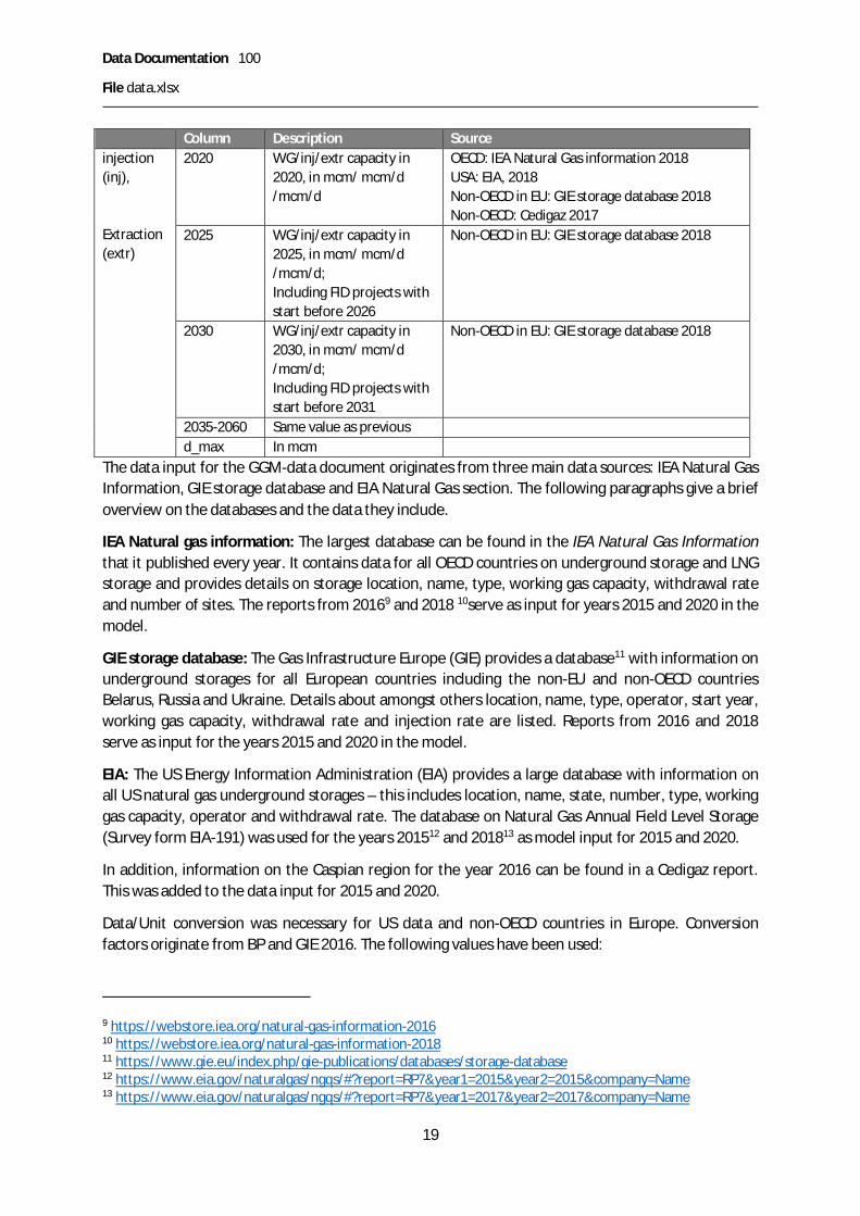
Column Description Sourceinjection(inj),
Extraction(extr)
2020 WG/inj/extr capacity in2020, in mcm/ mcm/d/mcm/d
OECD: IEA Natural Gas information 2018USA: EIA, 2018Non-OECD in EU: GIE storage database 2018Non-OECD: Cedigaz 2017
2025 WG/inj/extr capacity in2025, in mcm/ mcm/d/mcm/d;Including FID projects withstart before 2026
Non-OECD in EU: GIE storage database 2018
2030 WG/inj/extr capacity in2030, in mcm/ mcm/d/mcm/d;Including FID projects withstart before 2031
Non-OECD in EU: GIE storage database 2018
2035-2060 Same value as previousd_max In mcm
The data input for the GGM-data document originates from three main data sources: IEA Natural GasInformation, GIE storage database and EIA Natural Gas section. The following paragraphs give a briefoverview on the databases and the data they include.
IEA Natural gas information: The largest database can be found in the IEA Natural Gas Informationthat it published every year. It contains data for all OECD countries on underground storage and LNGstorage and provides details on storage location, name, type, working gas capacity, withdrawal rateand number of sites. The reports from 20169 and 2018 10serve as input for years 2015 and 2020 in themodel.
GIE storage database: The Gas Infrastructure Europe (GIE) provides a database11 with information onunderground storages for all European countries including the non-EU and non-OECD countriesBelarus, Russia and Ukraine. Details about amongst others location, name, type, operator, start year,working gas capacity, withdrawal rate and injection rate are listed. Reports from 2016 and 2018serve as input for the years 2015 and 2020 in the model.
EIA: The US Energy Information Administration (EIA) provides a large database with information onall US natural gas underground storages – this includes location, name, state, number, type, workinggas capacity, operator and withdrawal rate. The database on Natural Gas Annual Field Level Storage(Survey form EIA-191) was used for the years 201512 and 201813 as model input for 2015 and 2020.
In addition, information on the Caspian region for the year 2016 can be found in a Cedigaz report.This was added to the data input for 2015 and 2020.
Data/Unit conversion was necessary for US data and non-OECD countries in Europe. Conversionfactors originate from BP and GIE 2016. The following values have been used:
9 https://webstore.iea.org/natural-gas-information-201610 https://webstore.iea.org/natural-gas-information-201811 https://www.gie.eu/index.php/gie-publications/databases/storage-database12 https://www.eia.gov/naturalgas/ngqs/#?report=RP7&year1=2015&year2=2015&company=Name13 https://www.eia.gov/naturalgas/ngqs/#?report=RP7&year1=2017&year2=2017&company=Name

Data Documentation 100
File data.xlsx
20
1 m³ of LNG = 615 m³ of NG, 1ft³ = (12*0.0254)³ m³ and 11.4 TWh = 1 bcm of NG
Merging data from different data sources comes along with mismatching units and lack of detail. Thefinal data is in mcm for working gas capacity and mcm/d for withdrawal capacity. All informationfrom the different databases has undergone some processing in order to have the same format forall information. This included unit conversion in the first place. After, storages were assigned acategory according to their type (see Table 14 for assignments, where PEAK stands for peak shavingunit, SEAS for seasonal storage and LNGS for LNG storage) and a model node according to theirlocation. All data was then aggregated by model node and type such that each node has a maximumof three storage capacities assigned. At last, storages that cannot cover up to 2% of consumptionwith their capacity have been excluded from the model’s input.14
Table 14: Categories for different storage types
Type CategoryAbove ground PEAKAquifer SEASCavern PEAKCavern storage PEAKDepleted Field SEASDepleted gas field SEASDepleted gas/oil field SEASDepleted oil field SEASGranite cavern PEAKLine rock cavern PEAKLNG peak shaving unit PEAKLNG Storage LNGSSalt cavern PEAKSalt Dome PEAKSalt mine PEAKStorage field SEAS
Data.xlsx– Sheet M - Market powerThe model implements market power via a conjectural variation approach. Values range from 0 to 1,with 0 implying perfectly competitive behavior and 1 behavior à la Cournot. Values have been tunedin the calibration.
1) Assign domestic market power value (use EPS for 0 to prevent data reading errors.)2) Assign general export market power value.
14 There is an R-script available that aggregates the data from the internal data compilation file storage neededin sheet W. The script is called storage_data_processing_script.R and can be found with its accompanyingreadme.pdf in folder gas-setnav\data documentation\internal\Storage\R-script
Data Documentation 100
File data.xlsx
21
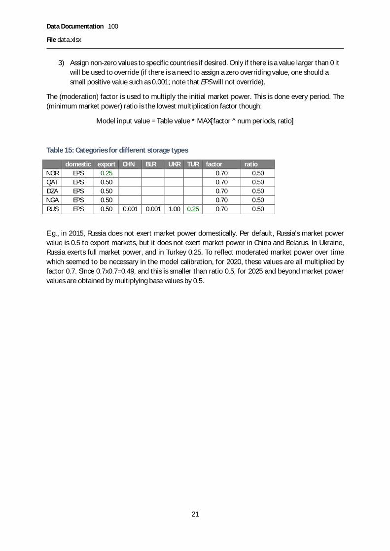
3) Assign non-zero values to specific countries if desired. Only if there is a value larger than 0 itwill be used to override (if there is a need to assign a zero overriding value, one should asmall positive value such as 0.001; note that EPS will not override).
The (moderation) factor is used to multiply the initial market power. This is done every period. The(minimum market power) ratio is the lowest multiplication factor though:
Model input value = Table value * MAX[factor ^ num periods, ratio]
Table 15: Categories for different storage types
domestic export CHN BLR UKR TUR factor ratioNOR EPS 0.25 0.70 0.50QAT EPS 0.50 0.70 0.50DZA EPS 0.50 0.70 0.50NGA EPS 0.50 0.70 0.50RUS EPS 0.50 0.001 0.001 1.00 0.25 0.70 0.50
E.g., in 2015, Russia does not exert market power domestically. Per default, Russia’s market powervalue is 0.5 to export markets, but it does not exert market power in China and Belarus. In Ukraine,Russia exerts full market power, and in Turkey 0.25. To reflect moderated market power over timewhich seemed to be necessary in the model calibration, for 2020, these values are all multiplied byfactor 0.7. Since 0.7x0.7=0.49, and this is smaller than ratio 0.5, for 2025 and beyond market powervalues are obtained by multiplying base values by 0.5.

Data Documentation 100
File data_proj.xlsx
22
File data_proj.xlsxProduction and consumption dataThis section describes how the GGM reference values for production and consumption have beenestablished. It documents sources and disaggregation approaches. To create the data in this fileseveral steps are needed. The following paragraphs explain how the data was obtained and fromwhich sources they originate.
1.1.6 Suggestions and traps that should be avoided§ Use consistent conversion rates from QBtu, Mtoe or TWh to bcm for all data types from all
data sources. Make the conversion rate adjustable in the worksheets and make sure that allcalculations adjust automatically based on the conversion rate.
1.1.7 Processing steps and internal data filesSince some data are proprietary we cannot make available all input data we have used. By describingthe input data, the processing steps, and the resulting input files we aim for maximum transparencyand to allow anyone else to reproduce the data sets from scratch if desired.
Three MS Excel files collect and compile the production and consumption data:
§ “WEO_Scenarios_Input_data.xlsx” has the general information for all countries except theones in the EU28
§ “gas_demand_production_europe.xlsx” gives data on EU28 countries§ “regional_split.xlsx” concerns five countries, USA, Canada, Russia, India, and China, that are
divided into more than one region. This means that country level data has to be brokendown to a more detailed level. The calculation of how country level production andconsumption data has been divided is done in this file.
Table 16 Summary of production and consumption data sources
EU Rest of WorldScenario Source Scenario Source
Production All scenarios PRIMES 2016reference
New Policies WEO 2017SustainableDevelopment
WEO 2017
Consumption Reference PRIMES 2016 New Policies WEO 2017DirectedVision
SET-Nav SustainableDevelopment
WEO 2017
ConsumptionSeasonality
All scenarios Eurostat 2014-2017
All scenarios DOE EIA 2007 + estimates basedon similar countries
ConsumptionSector shares
All scenarios SET-Nav All scenarios DOE EIA 2007 + estimates basedon similar countries
The IEA’s World Energy Outlook (WEO) 2016 450 Scenario and the WEO 2017 Current PoliciesScenario are not part of the data set in the open source version.
1.1.8 Explanation “WEO_Scenarios_Input_data.xlsx”In the open-source model version, we provide production and consumption data for 2015, andoutlook data for two scenarios: New Policies (NPS) and Sustainable Development (SDS).

Data Documentation 100
File data_proj.xlsx
23
Country level production and consumption data for the year 2015 were published in the 2018 report“World – Natural gas statistics” by the International Energy Agency (IEA). It was downloaded fromthe OECD iLibrary.
As the WEO spatial aggregation considers less regions than the Global Gas Model, the WEO regionalinformation had to be adjusted. Regional information (e.g. consumption) was split up according tothe countries’ share in the region in 2015.
The World Energy Outlook (WEO) 2017 provided worldwide production and consumption data forthree different scenarios (New Policies Scenario, Current Policies Scenario, and SustainableDevelopment Scenario). In addition, we take the 450 ppm Scenario from WEO 2016 (which wasdiscontinued in later editions of the WEO). Production data for the New Policies Scenario can befound on page 346, consumption data on page 339. Data on the production in the SustainableDevelopment Scenario can be found on page 645 and on consumption on page 452.15
As there was no data for every year in the modeling horizon, the missing ones between 2020 and2035 were interpolated linearly. To obtain values for the periods 2045 and 2050, the changebetween 2035 and 2040 was multiplied by 0.9 (for 2045 values), and by 0.72 (0.9x0.8) for 2050values, reflecting a moderated trend extrapolation. Values for 2055 and 2060 are the same as for2050.
Regional data was broken down to the country level by taking the production or consumption sharefrom 2015 and applying these shares to the following years.
1.1.9 Explanation of the data for Europe in file “gas_demand_production_europe”Production data for Europe is taken from the PRIMES European Reference Scenario 2016 as well asthe reference consumption. In addition, we have included SET-Nav pathways “Directed Vision”.16 Notonly the annual country level consumption can be found in the file, but also the sectoral share foreach period for residential heating, industry, power, and transport.
Furthermore, in order to distinguish several seasons, monthly data on the supply of gas provided byEurostat (n.d.) was used.
Three seasons: one with low consumption that includes months April through September, one withhigh consumption that consists of October until March with the exception of December, January andFebruary. The peak consumption period includes December and January.
Five seasons: one with low consumption that includes the months April through September, one withhigh consumption that consists of October until March with the exception of February and one weekin January, a peek week in January, and the peek month of February.
Exceptions:
· Netherlands – we have decreased Netherlands production outlook rather drasticallycompared to PRIMES 2016 reference to account for the phasing out of the Groningen field.
15 Current Policies data on production and consumption is available at p. 645 and 647 respectively. The 450Scenario from WEO 2016 has production data at p. 549, and consumption on pp. 551-623. Here,For the 450ppm Scenario, we use Total Primary Energy Demand (TPED) values for gas that are given in billion cubic meter(Mtoe in the WEO 2016 and that we converted to bcm)..16 Directed Vision, Diversification, Localisation, and National Champions

Data Documentation 100
File data_proj.xlsx
24
· Norway – we have modified reference production in a few years to smooth out somemoderate swings in values.
· Cyprus – Reference consumption in Cyprus started a period earlier than production. Ratherthan accounting for a small regasifier, we have adjusted production to take off a periodearlier.
1.1.10 Explanation of the “regional_split” for countries with multiple regionsFor all these countries the approach was similar: the different parts of the country were assigned tothe regions in the model, then the share of production and consumption of each region wascalculated for the year 2015 and multiplied with the WEO values.
1.1.10.1 USAProduction and consumption data for the USA were taken from the U.S. Energy InformationAdministration (EIA)
§ USA Census regions + Alaska:https://www2.census.gov/geo/pdfs/maps-data/maps/reference/us_regdiv.pdf
Please note that, for the USA, marketed production instead of gross production was used fordetermining regional shares. This is especially important since gross production in Alaska is about10% of the country’s production (and includes natural gas re-injected in the oil and gas production),but marketed production from Alaska is more than 10 times smaller. For marketed production referto:
https://www.eia.gov/dnav/ng/ng_prod_sum_a_EPG0_VGM_mmcf_a.htm
Outlook for future periods (https://www.eia.gov/outlooks/aeo/data/browser/#/?id=77-AEO2019®ion=0-0&cases=ref2019&start=2017&end=2050&f=Q&sourcekey=0).
We have assigned state level production published by the EIA to the ten GGM USA regions (Source:https://www.eia.gov/dnav/ng/ng_prod_sum_a_EPG0_FGW_mmcf_a.htm). This allowed calculatingregional shares in production for 2015. These shares are multiplied by the USA production referencevalue from the relevant WEO outlook.
Consumption values were also taken from the EIA (Sources:https://www.eia.gov/dnav/ng/ng_sum_snd_a_EPG0_VC0_Mmcf_a.htm andhttps://www.eia.gov/outlooks/aeo/data/browser/#/?id=77-AEO2019®ion=0-0&cases=ref2019&start=2017&end=2050&f=Q&sourcekey=0). The regional shares in consumptionfor the years were calculated and again multiplied by the US consumption reference value from therelevant WEO outlook.
1.1.10.2 CanadaWe have assigned state level production and consumption published by the National Energy Board(NEB) (Source: https://apps.neb-one.gc.ca/ftrppndc/dflt.aspx?GoCTemplateCulture=en-CA) to thetwo GGM Canada regions. This allowed calculating regional shares in production (respectivelyconsumption) for the different years. These shares are multiplied by Canada’s production(respectively consumption) reference value from the relevant WEO outlook.
1.1.10.3 RussiaState level production values are from the paper “Shrinking surplus: the outlook for Russia’s sparegas productive capacity“ published by the Oxford Institute for Energy Studies in 2018 (Source:

Data Documentation 100
File data_proj.xlsx
25
https://www.oxfordenergy.org/wpcms/wp-content/uploads/2018/12/Shrinking-surplus-the-outlook-for-Russias-spare-gas-productive-capacity-Energy-Insight-42.pdf), figure on p. 9. State levelinformation was assigned to the four GGM Russia regions, obtaining a share per region in totalRussian production in 2015. These shares are multiplied by the Russia production reference valuefrom the relevant WEO outlook.
Consumption was calculated according to the regional share of total GDP. As Sakhalin’s share is verysmall, it was assumed to be equal to zero. Again, these shares are multiplied with the Russiaconsumption reference value from the relevant WEO outlook.
1.1.10.4 ChinaWe have assigned state level production and consumption published by the Statistical Yearbook 2017(Source: http://www.stats.gov.cn/tjsj/ndsj/2017/indexeh.htm) to the six GGM nodes in China. Thisallowed calculating regional shares in production (respectively consumption) for the different years.These shares are multiplied by the Chinese production (respectively consumption) reference valuefrom the relevant WEO outlook.
1.1.10.5 IndiaWe have assigned state level production published by the Ministry of Petroleum and Natural Gas(Source: http://petroleum.nic.in/indian-petroleum-and-natural-gas-statistics) to the four GGM Indiaregions. This allowed calculating regional shares in production for the different years. These sharesare multiplied by the Indian production reference value from the relevant WEO outlook.Consumption was calculated according to the share of total GDP. Again, these shares are multipliedwith the Indian consumption reference value from the relevant WEO outlook.

Data Documentation 100
Files data_calib.xlsx
26
Files data_calib.xlsxThere is a data_calib.xlsx for each scenario.
CalibrationCalibration is the process to reconcile model outputs with reference values by means of input dataadjustments. In the process, one should take care to make logical and transparent choices, andmaintain consistency. Parameter choices should still make sense if, for instance, in a differentscenario or a what-if analysis, a country would not be an exporter but an importer. In contrast toperfectly competitive market models, multi-country oligopolistic market models are generally muchharder to calibrate. Calibrating the GGM for a new scenario takes an experiences analyst at leastseveral days. Especially after a major revision of the input data set this may extend to several weeks.
In the calibration of GGM we have focussed on annual production and consumption values, forindividual countries in the EU and other European countries, and at the regional level in the rest ofthe world. The parameters adjusted in the calibration are production costs and capacities, referenceprices, and market power assumptions. We have, e.g., not adjusted price-demand elasticities in thecalibration. The model creates regional and country-level calibration reports showing the differencesbetween model outcomes and reference values.
Given that reference production and consumption values must be consistent, if global consumptionis too low (high), global production must also be too low (high). Let’s consider a few examples:
· If, for example, Russia does not produce enough (its production is lower than the referencevalue) but its consumption is high enough. That means its exports are too low. This can bedue: 1) too high production costs, 2) too low willingness to pay in export markets, 3) too highmarket power of Russia.
· If, for example, China does not consume enough in a future year, it may be due to 1) too lowdomestic production, 2) too low willingness to pay, 3) too high market power level ofexporters, 4) too high investment costs for pipelines or regasifiers, 5) too low expansionlimits on infrastructure expansions, or 6) too high production costs in exporting countries.
Because of trade, the global market is a system of communicating vessels. Lowering production costsin one country will spill over internationally and increase consumption in many regions – albeit ifoften by modest amounts.
Which parameter values to adjust is up to some extent arbitrary. The analyst needs to combinemarket knowledge with model expertise and trade off choices.
We usually calibrate the base year by itself. This way we create a good foundation for costs, pricesand market power assumptions with a model that solves quickly. Once the model reproduces thebase year adequately close, we start calibrating future years.
There are many good and defendable ways to adjust parameter values and calibrate a model. Thereare also many wrong ways to calibrate a model. A wrongly calibrated model may give biased resultsfor a scenario analysis hat are not due to modelling and market logic but due to invalid parameterchoices.

Data Documentation 100
Files data_calib.xlsx
27
Table 17: Sheets in workbook data_calib.xlsx
Sheet DescriptionReadmeGlobLoss Account for value chain losses and mismatches in outlooksPCapCalib Production capacity parameters adjustmentsPCostCalib Production cost parameters adjustmentsPriceCalib Price /Willingness to pay adjustment parameters
Reconciling value chain lossesMost outlooks, including IEA WEO, project the same global production and consumption levels forfuture years. GGM accounts for losses. Losses in pipelines, the LNG value chain and storages. Toaccount for this, we reduce the yearly consumption values in non-European countries by somepercentage. We have chosen to only do this for non-European countries so that model outcomes forconsumption would match demand projects by PRIMES and SET-Nav. Since international trade, andespecially the amount of LNG traded, varies significantly among scenarios, the consumptionreductions have to be calibrated by scenario.
Table 18 describes the contents of sheet GlobLoss in workbook data_calib.xlsx
Table 18: GlobLoss
Column Description SourceYear Percentage deduction for consumption of non-European
countries to account for inconsistencies in differentoutlooks and losses in global value chains.
Tuned during calibrationof specific scenario
See section 0 below to see how GlobLoss is used.
Production calibrationDetailed and consistent production cost and capacity data is not available. We derive input values forproduction costs and capacities based on own assumption supported by some available information.The file “production costs some data points v0 20190408-RE.docx” presents some of thisinformation.
Every production node in GGM has several calibration parameters for costs, and for capacities. Thesevalues vary by scenario and are stored in the file data_calib.xlsx, in folder data\SET-Nav\<scenario>.
For each resource at each production node, we indicate the share of the resource in the totalproduction capacity at the node, and the slack percentage by which the capacity should be higherthan the reference production. Table 19 indicates the columns in the capacity calibration sheet.
Table 19: PCapCalib
Column Description SourceRegion Auxiliary Own creationNode Production node Own creationR1,R2,R3 Share of resource in total capacity Own creation2015-2060 Multiplication factor applied to reference production Own creation, tuned during

Data Documentation 100
Files data_calib.xlsx
28
to calculate production capacity calibrationWhen removing the logarithmic (so-called Golombek) production function from a previous GGMversion we have established a linear approximation and introduced multiple resources (at themoment three: R1, R2, R3, but this can be easily adjusted). To allow a steep cost increase close tocapacity, in line with Golombek, we choose a steep cost curve for a modest capacity (R3). We assignvalues to R1 so that significant amount is produced virtually always, and to R2 to reflect the rest. Theactual value choices for capacities and costs together determine the cost curve. The capacity sharesare therefore somewhat arbitrary. For convenience, to limit the degrees of freedom and increasetransparency, we have assigned the same resource capacity shares to all countries. R1: 50%, R2: 46%and R3: 4%. In the further calibration, we have only adjusted cost parameters
Based on experience, slack capacities should be at least a few percent, but not more than 7-10%.Values used are in the 3%-5% range, leading to multiplication factors in the 1.03-1.05 range.
Some data suggests that Russian marginal production cost are in the range € 25-35 / kcm.17 For theUSA, marginal supply costs vary around $ 70-100 / kcm, or € 60-85 / kcm.18 Parameter values shouldreflect that marginal cost are the cost of the most expensive well with active production. To limit thedegrees of freedom, we have chosen to adjust one value “base cost” for each production node in thecalibration and use identical multiplication factors to calculate different parameter values used (RefSection 0). Table 20 shows the columns in the cost calibration sheet.
Table 20: PCostCalib
Column Description SourceRegion Auxiliary Own creationNode Production node Own creation
base cost Marginal cost of the first unit Own, tuned during base year calibrationR1-R3 c Multiplication factor for lowest
marginal cost of the resourceOwn creation, See Section 0 for calculationexplanations.
R1-R3 q Multiplication factor for highestmarginal cost of the resource
Own, See Section 0 for calculationexplanations.
y 2015 1 Base year valuesy 2020-2060 Cost adjustment factor Own, tuned during scenario calibration
A small capacity share but high cost value for (R3,q) allows a very steep increase in the last part ofthe production cost function, similar to the Golombek cost function.
See section 0 below to see how production calibration parameters are used to calculate input valuesin the model implementation.
Consumption calibrationFor each consumption node, the model calculates an inverse demand curve for every season, basedon reference consumption, price, seasonal loads, sector shares, and sectoral price-demandelasticities.
17 E.g., https://eegas.com/rep2017q2-prod-e.htm Accessed 8 Apr 201918 www.eia.gov/dnav/ng/ng_pri_sum_dcu_nus_a.htm, www.eia.gov/dnav/ng/hist/rngwhhdm.htm,www.eia.gov/todayinenergy/prices.php, www.eia.gov/dnav/ng/hist/n9190us3m.htm (8 Apr 2019)

Data Documentation 100
Files data_calib.xlsx
29
We do not have price information for many countries. Market prices vary over time and are ratherindependent from actual consumption levels, partly due to contracts and index pricing still stronglycorrelated with crude oil prices. We wish the model to reflect prices that are relatively close to realworld prices, but not too dependent on the base year of the model.
Table 21 Selected gas prices (Based on BP 2018, using conversion 38 MMbtu/cm)
LNG Natural gasJapan Japan / Korea Germany UK Netherlands USA Canada
2013 $ 614 $ 629 $ 408 $ 404 $ 371 $ 141 $ 1112014 $ 621 $ 527 $ 346 $ 314 $ 309 $ 165 $ 1472015 $ 392 $ 283 $ 255 $ 248 $ 245 $ 99 $ 762016 $ 264 $ 217 $ 187 $ 178 $ 173 $ 94 $ 592017 $ 308 $ 271 $ 213 $ 221 $ 217 $ 112 $ 61
Table 22 GGM references prices 2015 selected countries
Consumption node Price €/kcmCAN_E 80CAN_W 50USA18 70 - 95DEU 160GBR 160NLD 155JPN 215KOR 200
The sectoral price-demand elasticities are the same for every country. (See section 1.1.2 , Table 6).Sector shares and seasonal loads are stored in the file data.xlsx for non-EU countries (See Section 0)and in data_proj.xlsx for EU-countries (see Section 1.1.9). Other parameters for calibratingconsumption are included in Table 23.

Data Documentation 100
Files data_calib.xlsx
30
Table 23 PriceCalib
Column Description SourceRegion AuxiliaryNode Consumption node Own creationprice Reference price Tuned during calibration of base year 2015L,H,P Seasonal multiplication factor for
reference priceOwn creation
2015 1 2015 price should be the one in column “price”2020-2060 Multiplication factor for reference
priceTuned during calibration of specific scenario
Hemisphere Auxiliary To provide default seasonal price adjustments

Data Documentation 100
Parameter value calculations
31
Parameter value calculationsGAMS file in_prod.gmsCalculation of production capacity and production cost function parameters, cost_pl and cost_pq in
= cost . + . .
Table 24 Input parameters determined in in_prod.gms
Parameter Description Calculationref_p(n_p,y) Reference production level in mcm/d Transform bcm/y to mcm/dcap_p(n_p,r,y) Production capacity by resource Reference production plus a
margin for slackcost_pl(n_p,r,y) Constant term in unit production costs See below
cost_pq(n_p,r,y) Linearly increasing term in unit productioncosts
See below
Given the scenario choice for EU data (parameter %SET-Nav%) and non-EU data (parameter%WEO%), the production is read from data_proj.xlsx. The model code transforms bcm/y to mcm/dby multiplying by 1000/365 = 1/0.365
As described above in Section 0 for each resource at each production node, we indicate the share ofthe resource in the total production capacity at the node, and the slack percentage by which thecapacity should be higher than the reference production:
NODE R1 R2 R3 2015 2020USA_2 0.50 0.46 0.04 1.05 1.05USA_3 0.50 0.46 0.04 1.03 1.03
Now, for instance, for USA_2: resource R1 accounts for 50% of the total production capacity. Theslack percentage is 5% in years 2015, 2020, etc.… For USA_3, resource R3 accounts for 4% of totalproduction capacity. The slack percentage is 3% in years 2015, 2020, etc…
If for a production node the reference production is 100 mcm/d, with an R1 capacity share of 0.50and 5% slack, the production capacity of resource R1 at that production node is 100x0.5x1.05=52.5mcm/d.
To calculate the linear and quadratic cost terms in each year for each resource at each productionnode, we apply multiplication factors to the base cost.
“linear” “quadratic”base R1 R2 R3 R1 R2 R3 y ycost c c c q q q 2015 2020
USA_2 12 1 1 1 1 5 8 1 1.15
An example of the relation between multiplication factor values and marginal costs.
USA_2, Base cost = 12
§ R1o Multiplication factor (R1,c)=1, MC(R1) first unit: 12x1=12
Data Documentation 100
Parameter value calculations
32
o Multiplication factor (R1,q)=1, MC(R1) at full capacity: 12x1=12§ R2
o Multiplication factor (R1,c)=1, MC first unit: 12x1=12o Multiplication factor (R1,q)=5, MC(R2) at full capacity: 12x5=60
§ R3o Multiplication factor (R1,c)=1, MC first unit 12x1=12o Multiplication factor (R1,q)=8, MC(R3) at full capacity: 12x8=96
USA_2, in 2020. Multiplication factor (y,2020): 1.15
§ This multiplication factor is applied in addition to the cost inflator (see Section 1.1.3).Assuming this is 3%, and five year periods:
§ MC(R3) at full capacity: 12x8x1.15x(1.03)5 = 127.9838578
GAMS file in_cons.gmsCalculation of intercept and slope of demand curves: = − ∑ (with tthe supplier index)
Table 25 Input parameters determined in in_cons.gms
Parameter Description Calculationref_c(n_c,y) Reference consumption level in mcm/d Transform bcm/y to mcm/d, adjust
for losses; see belowslp(n_c,d,y) Slope of the seasonal inverse demand curve See belowint(n_c,d,y) Intercept of the seasonal inverse demand curve See below
As discussed in Section 0, we combine outlooks for the EU gas market developed with PRIMES and inSET-Nav with IEA WEO outlooks for the global market. The net imports by the EU in the EU outlooksdo not necessarily match the net exports to the EU in the WEO outlooks. Additionally, outlooksignore value chain losses. When determining reference consumption values in GGM we account forboth discrepancies.
In in_prod.gms, we calculate ref_p_glob(y), the global aggregate reference production.
In in_cons.gms, we calculate ref_c_glob(y), the global aggregate reference consumption.
GlobLoss is read from data_calib.xlsx (See Section 0).
Given the scenario choice for EU data (parameter %SET-Nav%), and for other countries (based onparameter %WEO%) the reference consumption is read from data_proj.xlsx.
For all countries, the bcm/y values are transformed to mcm/d values.
For countries not in EU or Other European, we adjust the reference consumption values to accountfor global losses and the outlooks mismatch by using the following multiplication factor:
(1-l_glob(y))* ref_p_glob(y)/ref_c_glob(y).
By adjusting global loss percentages in the calibration, the reference values for consumption can beadjusted further if necessary.

Data Documentation 100
Parameter value calculations
33
To calculate the seasonal, country level demand curves, we determine:
Seasonal sector load: country load * sector share * seasonality.
Reference price:
[base year price] * [seasonal adjustment] * [price inflator] * [calibration adjustment]
Reference consumption:
EU: [reference year] * [seasonal sector share for specific year]
Other: [reference year] * [seasonal adjustment] * [sector share]
Seasonal sector intercept: int = price_ref * (1-1/elas) = 1−
Seasonal sector slope: slp = -price_ref / (elas*cons_ref) =
The seasonal sector slopes and intercepts are aggregated to country level slopes and intercepts19:
slp(n_c,d,y) = (1/SUM(k,1/dsss(n_c,k,d,y))); =∑
int(n_c,d,y) = slp(n_c,d,y) * SUM(k, dssi(n_c,k,d,y)/dsss(n_c,k,d,y)); = ∑
GAMS file in_arcs.gmsThis file calculates capacities, operational and investment costs, losses, and allowable expansions.The code also assigns specific sets, arc types, start and end nodes of arcs, etc.
Note that the table continues at the next page.
Table 26 Input parameters determined in in_arcs.gms
Parameter Description Calculationl_a(a) Loss rate on arc Pipelines: length x loss rate per unit of distance
Liquefiers: identical input value for allRegasifiers: : identical input value for allVessels: length x loss rate per unit of distance
cap_a(a,y) Exogenous arc capacityin specific year
Read from input table, transformed from bcm/a to mcm,/d, andcorrected with loss percentage assuming that capacities areoutput based
cost_a(a,y) Operational arc costs inspecific year
Pipelines: length (onshore/offshore) x base cost per unit ofdistance x cost inflatorLiquefiers: identical input value for all, possibly calibrationadjustment x cost inflatorRegasifiers: identical input value for all, possibly calibrationadjustment x cost inflator
19 This is an approximation, as the actual aggregate inverse demand curve is piecewise linear.
Data Documentation 100
Parameter value calculations
34
Parameter Description CalculationVessels: length x cost per unit of distance x cost inflator
inv_a(a,y) Arc unit investmentcosts per mcm/d
Pipelines: based on length, onshore/offshore, and cost per unit(see Section 1.1.1), calibration adjustment, and loss adjustment(see cap_a), x cost inflator, scaled by number of years betweentwo periods.Liquefiers and regasifiers: the same calculation as for pipelines,but with length=1 and no offshore part. (See 1.1.1)
d_a_max Maximum allowable arcexpansion
First stage, second stage, all later stages. (Note a one period gapbetween investment decision and availability of newly investedcapacity.)
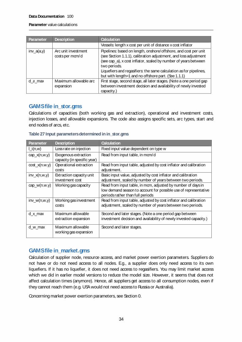
GAMS file in_stor.gmsCalculations of capacities (both working gas and extraction), operational and investment costs,injection losses, and allowable expansions. The code also assigns specific sets, arc types, start andend nodes of arcs, etc.
Table 27 Input parameters determined in in_stor.gms
Parameter Description Calculationl_i(n,w) Loss rate on injection Fixed input value dependent on type wcap_x(n,w,y) Exogenous extraction
capacity (in specific year)Read from input table, in mcm/d
cost_x(n.w.y) Operational extractioncosts
Read from input table, adjusted by cost inflator and calibrationadjustment.
inv_x(n,w,y) Extraction capacity unitinvestment cost
Basic input value, adjusted by cost inflator and calibrationadjustment, scaled by number of years between two periods.
cap_w(n.w.y) Working gas capacity Read from input table, in mcm, adjusted by number of days inlow demand season to account for possible use of representativeperiods rather than full periods
inv_w(n,w,y) Working gas investmentcosts
Read from input table, adjusted by cost inflator and calibrationadjustment, scaled by number of years between two periods.
d_x_max Maximum allowableextraction expansion
Second and later stages. (Note a one period gap betweeninvestment decision and availability of newly invested capacity.)
d_w_max Maximum allowableworking gas expansion
Second and later stages.
GAMS file in_market.gmsCalculation of supplier node, resource access, and market power exertion parameters. Suppliers donot have or do not need access to all nodes. E.g., a supplier does only need access to its ownliquefiers. If it has no liquefier, it does not need access to regasifiers. You may limit market accesswhich we did in earlier model versions to reduce the model size. However, it seems that does notaffect calculation times (anymore). Hence, all suppliers get access to all consumption nodes, even ifthey cannot reach them (e.g. USA would not need access to Russia or Australia).
Concerning market power exertion parameters, see Section 0.

Data Documentation 100
References
35
ReferencesNote that several data appendices have separate references lists.
BP 2018 Statistical review of world energy
DOE EIA 2007 Personal communication with Justine Barden concerning international pipelinecapacities, seasonal load factors, etc.
DOE EIA: https://www.eia.gov/naturalgas/data.php
Egging, Rudolf G. 2010. Multi-Period Natural Gas Market Modeling-Applications, StochasticExtensions and Solution Approaches, Doctoral dissertation, University of Maryland, CP, USA,http://hdl.handle.net/1903/11188.
Egging, Ruud. 2013. Benders decomposition for multi-stage stochastic mixed complementarityproblems – Applied to a global natural gas market model. European Journal of Operational Research226: 341-353.
Ruud Egging, Tobias Baltensperger, and Asgeir Tomasgard 2018 Solving equilibrium problems usingconvex optimization (in Review)
Egging, Ruud, Steven A. Gabriel, Franziska Holz, and Jifang Zhuang (2008): A Complementarity Modelfor the European Natural Gas Market. Energy Policy, Vol. 36 (7), pp. 2385-2414.
Egging, Ruud, Franziska Holz, Christian von Hirschhausen, and Steven A. Gabriel (2009): RepresentingGaspec with the World Gas Model. The Energy Journal, Vol. 30, Special Issue „World Natural GasMarkets and Trade: A Multi-Modeling Perspective“, pp. 97-117.
Egging, Ruud, Franziska Holz, and Steven A. Gabriel (2010): The World Gas Model: A Multi-PeriodMixed Complementarity Model for the Global Natural Gas Market. Energy, Vol. 35 (10), pp. 4016-4029.
Egging, Ruud and Franziska Holz (2016): Risks in Global Natural Gas Markets: Investment, Hedgingand Trade. Energy Policy, Vol. 94, pp. 468-479.
ENTSO-G https://www.entsog.eu/maps#
Eurostat http://appsso.eurostat.ec.europa.eu/nui/show.do?dataset=nrg_103m&lang=en
GAMS www.gams.com
GIE n.d. a https://www.gie.eu/index.php/gie-publications/maps-data/lng-map
GIE n.d. b https://www.gie.eu/index.php/gie-publications/databases/lng-investment-database
GIIGNL 2011
GIIGNL 2016https://giignl.org/sites/default/files/PUBLIC_AREA/Publications/giignl_2016_annual_report.pdf
GIIGNL 2017https://giignl.org/sites/default/files/PUBLIC_AREA/Publications/giignl_2017_report_2.pdf

Data Documentation 100
References
36
GIIGNL 2018https://giignl.org/sites/default/files/PUBLIC_AREA/About_LNG/5_LNG_Markets_And_Trade/giignl_2018_annual_report.pdf
Holz, Franziska, Hanna Brauers, Philipp M. Richter, and Thorsten Roobeek (2017): Shaking DutchGrounds Won't Shatter the European Gas Market. Energy Economics, Vol. 64, pp. 520-529.
Holz, Franziska, Philipp M. Richter, and Ruud Egging (2015): A Global Perspective on the Future ofNatural Gas: Resources, Trade, and Climate Constraints. Review of Environmental Economics andPolicy, Vol. 9 (1), pp. 85-106.
Holz, Franziska, Philipp M. Richter, and Ruud Egging (2016): The Role of Natural Gas in a Low-CarbonEurope: Infrastructure and Supply Security. The Energy Journal, Vol. 37, Special Issue 3, pp. 33-59.
IEA 2018 “World – Natural gas statistics”. OECD, Paris. online statistics from the iLibrary
IEA WEO 2016 World Energy Outlook. OECD, Paris.
IEA WEO 2017 World Energy Outlook. OECD, Paris.
Kotek, Peter, Borbála Takácsné Tóth, Pedro Crespo del Granado, Ruud Egging, Franziska Holz, Auroradel Valle Díez (2018): Case study on Projects of Common Interest and gas producers pricing strategy.SET-Nav Deliverable D.6.6 (www.set-nav.eu
Oostvoorn, Frits van, et al. (2003) Long-term gas supply security in an enlarged Europe, ECNdiscussion paper ECN-C-03-122.

Data Documentation 100
Appendix A: How to Run GGM?
37
Appendix A: How to Run GGM?The Global Gas Model (GGM) is a partial equilibrium model to analyze the investment decisions ingas transportation and storage infrastructure and volumes of production, consumption, and trade,while considering market power. The model is currently set up for a time horizon up to the year 2050in steps of five years. It is written as a quadratic program, and implemented in GAMS as aquadratically constrained program (QCP) solved with CPLEX.
The model serves to analyze the consequences of long-term projections of consumption andproduction values of the global natural gas market on infrastructure investments and trade. Themodel requires a sophisticated calibration and is thus to be handled with caution. Any changes in thecode or data should be based on profound economic and modelling knowledge.
Version and licenseThis work is licensed under the MIT License (MIT).
Copyright (c) 2019 Ruud Egging (NTNU), Franziska Holz (DIW Berlin)
Permission is hereby granted, free of charge, to any person obtaining a copy of this software andassociated documentation files (the "Software"), to deal in the Software without restriction,including without limitation the rights to use, copy, modify, merge, publish, distribute, sublicense,and/or sell copies of the Software, and to permit persons to whom the Software is furnished to doso, subject to the following conditions:
The above copyright notice and this permission notice shall be included in all copies or substantialportions of the Software.
The software is provided "as is", without warranty of any kind, express or implied, including but notlimited to the warranties of merchantability, fitness for a particular purpose and noninfringement. Inno event shall the authors or copyright holders be liable for any claim, damages or other liability,whether in an action of contract, tort or otherwise, arising from, out of or in connection with thesoftware or the use or other dealings in the software.
GGM in shortNote that the table continues at the next page.
GGM § A multi-period model for analyzing the world natural gas market.§ Country level; with large countries disaggregated (USA, CAN, RUS, CHN, IND).§ Focus on infrastructure investment and trade, taking into account market
power.§ Production, pipelines, liquefaction, regasification, shipping, storage.§ Implemented in GAMS.§ Input data files are MS Excel workbooks.
Inputs (Country and sub-country level)§ Reference values for production, consumption, prices, market power for base
year and future years’ projections.§ Capacities, investment and operational costs, depreciation and loss rates of
production, transportation, and storage infrastructure.§ Demand seasonality, sector shares and elasticities, production costs.

Data Documentation 100
Appendix A: How to Run GGM?
38
Outputs (Country and sub-country level)§ Pipeline, liquefaction, regasification, storage expansions and utilization.§ Seasonal production, consumption, trade and prices.§ Sector profits, costs, consumer surplus and social welfare impacts.
Model structureGGM is a multi-period optimization model determining the expansion of transportation and storagecapacities given detailed characteristics for production, consumption and infrastructure, consideringthe global context. Over 90 countries distributed over nine world regions are incorporated in thedata set. The current data set considers 109 consumption nodes, 93 production nodes, 50 storagenodes as well as 28 LNG liquefaction and 50 regasification nodes. Reference data points forproduction and consumption are exogenously determined, as is market power which is consideredfor some exporting countries. Infrastructure capacities are exogenously given but can beendogenously expanded.
Folder structureThe code files and data files that make up the GGM are distributed over several file folders. The mainfolder of the (deterministic) GGM contains several subfolders.§ data contains all input data files. See below for an overview of what these files contain.§ gdx contains the intermediate and output files of the model in the .gdx format. This is the GAMS
data exchange format from which the results can be further processed.§ model contains the GAMS files with the model equations and the solve statement.§ reports includes the GAMS files for the reporting of the model results.§ geo_map contains scripts and files for a plotting and mapping of model results§ excel contains output files in xlsx format.
Model filesTo structure the entire model code, different GAMS files are specified for specific purposes. Thefollowing table connects the relevant GAMS files on the left with a short contextual description onthe right. Note that the table continues at the next page.
GAMS file Descriptionmain.gms Main model file from which the model is run__READ_ME.txt License filecreate_excel_dumps.gms Transfers calibration results, results for the IIASA IAMC platform, and
results for the geo-maps tool to MS Excel files.merge_gdx_files.gms Merges results from different scenarios and transfers them to MS
Excel.DATA2015.gms, 2060.gms Definition of the years setall_input_data.gms File from which all other data files are includedin_arcs.gms Definition and declaration of all transportation (“arc”) data, i.e.
pipelines, liquefiers, shipping, regasifiersin_cons.gms Preparation of all consumption datain_market.gms Definition of market access and market powerin_prod.gms Preparation of all production datain_sets_parms.gms Declaration and processing of all sets and parametersin_stor.gms Preparation of all storage data

Data Documentation 100
Appendix A: How to Run GGM?
39
MODELall_eq_and_var.gms All model equations and variablessolve.gms Solve statementREPORTINGreport.gms Calculates report values and transfers them to gdx files .
Model inputAs described in previous sections of this document, this version of the model uses three MS Excelinput files.
Table 28 MS Excel workbooks with input data
File name Location Type of data Commentdata.xlsx data\set-nav Scenario independent datadata_proj.xlsx data\set-nav Future projections consumption and
production by scenario + EU demandsector shares and demand seasonality
Seasons andsectors non-EU arein data.xlsx
data_calib_<scenario>.xlsx data\set-nav\ Calibration data for production andconsumption
<scenario> iscurrently SDS-Vision or NPS-Ref
data.xlsx contains input data in corresponding sheets (see Section 0 for more details):· N for all data concerning nodes;· A for all data concerning arcs, i.e. pipelines, LNG and regasification terminals;· V for all data concerning vessels, i.e. shipping distances;· W for all data concerning storage capacities;· M for all data concerning market power; and· Other for all other data.
Model executionTo run the model, follow these steps:
1. Install GAMS with a license that can solve QCP.2. Open the _GGM.gpr file in the main folder. This is the GAMS project file, and opening it by
double clicking correctly sets the working directory.3. Use “CTRL+o” to open new files, then double click the file main.gms. This is the main file of
the model and includes all data processing, model set up, and reporting files.4. On lines 17-20 of main.gms select the scenario that should be analyzed.5. To run the model, select a scenario and press F9.6. If desired, open, select a scenario and execute create_excel_dumps.gms7. If desired, open and execute merge_gdx_files.gms
Model output reports and suggested gdx layoutThe output of this model version includes six types of gdx reports. The report generating code forthese is found in the folder reports. This is included by the file main.gms when the model is run viathe include file reports.gms. Formatted Excel reports can be created using create_excel_dumps.gmsor merge_gdx_files.gms.

Data Documentation 100
Appendix A: How to Run GGM?
40
1.1.11 Mass balancesrep_mass_bal.gms shows the mass balances, i.e. it depicts the consumption, production, incomingand outgoing pipeline and LNG flows, storage injections and extraction, and market prices andmarginal production costs on country (yearly, bcm) and node level (seasonal, mcm/d). Using drag anddrop, the layout of gdx files in the GAMS interface can be adjusted. Suggested layout:
Table 29 Country mass balance
+ - 0Prod pipe LNG stor TOT Cons pipe LNG stor TOT price
RUS RUS RUS 2015 642 428 48 1119 447 609 14 49 1119 74RUS RUS RUS 2020 693 345 24 1062 445 543 50 24 1062 79RUS RUS RUS 2025 718 349 24 1091 446 570 51 24 1091 83RUS RUS RUS 2030 749 384 24 1157 430 651 51 24 1157 96
Table 30 Nodal mass balance
+ - 0Prod pipe LNG stor TOT Cons pipe LNG stor TOT price MC
RUS RUS RUS_E 2015 L 69 69 69 69 92RUS RUS RUS_E 2015 H 57 57 57 57 92RUS RUS RUS_E 2015 P 50 50 50 50 107RUS RUS RUS_S 2015 L 37 37 37 37 24RUS RUS RUS_S 2015 H 37 37 37 37 24RUS RUS RUS_S 2015 P 37 37 0 37 37 24RUS RUS RUS_VU 2015 L 108 1235 148 1491 948 543 0 1491 75 75RUS RUS RUS_VU 2015 H 108 1107 0 1215 822 167 227 1215 74 74RUS RUS RUS_VU 2015 P 108 756 0 864 813 45 6 864 75 75RUS RUS RUS_W 2015 L 1637 115 1752 301 1452 0 1752 70 70RUS RUS RUS_W 2015 H 1611 0 1611 255 1356 0 1611 67 67RUS RUS RUS_W 2015 P 1556 0 1556 267 945 344 1556 63 63RUS RUS RUS_E 2020 L 70 70 70 0 70 95
1.1.12 Calibrationrep_calib.gms depicts the calibration results on country and region level, in billion cubic meter (bcm).The report shows reference values and model outcomes for production and consumption, andabsolute and relative deviations. Showing % is only possible when data are transferred or copied toMS Excel.
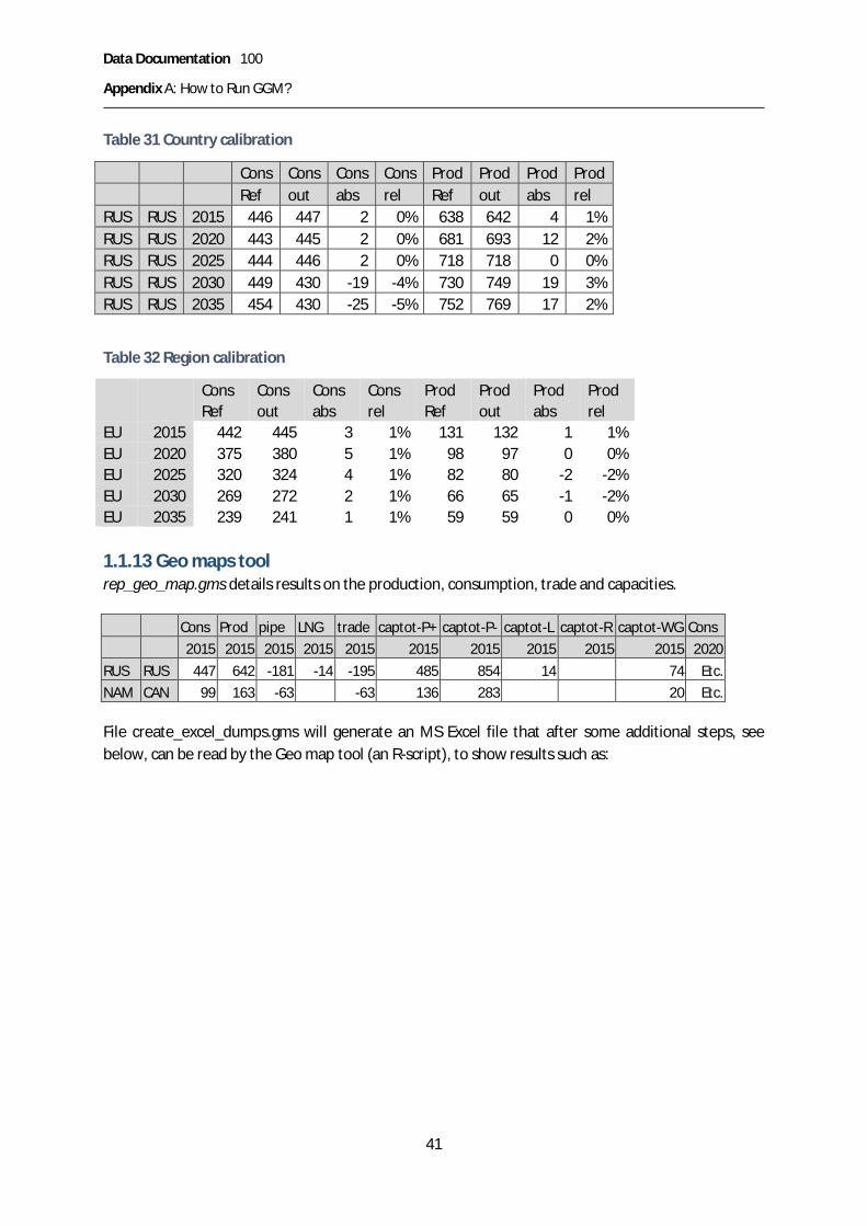
Data Documentation 100
Appendix A: How to Run GGM?
41
Table 31 Country calibration
Cons Cons Cons Cons Prod Prod Prod ProdRef out abs rel Ref out abs rel
RUS RUS 2015 446 447 2 0% 638 642 4 1%RUS RUS 2020 443 445 2 0% 681 693 12 2%RUS RUS 2025 444 446 2 0% 718 718 0 0%RUS RUS 2030 449 430 -19 -4% 730 749 19 3%RUS RUS 2035 454 430 -25 -5% 752 769 17 2%
Table 32 Region calibration
Cons Cons Cons Cons Prod Prod Prod ProdRef out abs rel Ref out abs rel
EU 2015 442 445 3 1% 131 132 1 1%EU 2020 375 380 5 1% 98 97 0 0%EU 2025 320 324 4 1% 82 80 -2 -2%EU 2030 269 272 2 1% 66 65 -1 -2%EU 2035 239 241 1 1% 59 59 0 0%
1.1.13 Geo maps toolrep_geo_map.gms details results on the production, consumption, trade and capacities.
Cons Prod pipe LNG trade captot-P+ captot-P- captot-L captot-R captot-WG Cons2015 2015 2015 2015 2015 2015 2015 2015 2015 2015 2020
RUS RUS 447 642 -181 -14 -195 485 854 14 74 Etc.NAM CAN 99 163 -63 -63 136 283 20 Etc.
File create_excel_dumps.gms will generate an MS Excel file that after some additional steps, seebelow, can be read by the Geo map tool (an R-script), to show results such as:

Data Documentation 100
Appendix A: How to Run GGM?
42
The outcome of the Global Gas Model (GGM) is processed in an R Script in order to generate somevisualization tools and standard result graphs. See folder GGM/geo_map;WorldMaps_ProjectFile.Rproj and readme_maps-plots.html. The general workflow is as follows:
§ Model optimization and generation of an output file from GAMS§ Processing of Data in R for visualization purposes§ Generation of plots and maps in R
1.1.14 Steps for generating html-plots with R to visualize GGM results
1. Install R and R Studio, e.g., from§ https://cran.r-project.org/bin/windows/base/§ https://www.rstudio.com/products/rstudio/download/
2. Open the project file WorldMaps_ProjectFile.Rproj located in folder GGM/geo_map (R Studiowill open)
3. Open these four scripts in this order and run each of them separately using Ctrl + Alt + R20, 21
§ data_file_generation_maps.R
20 This may take a while when executed for the first time. R will download and install all necessary packages.21 If only a chunk of the code needs to be run, mark the code and press Ctrl + Enter; for only one line, move thecursor to the line and press [RUN]

Data Documentation 100
Appendix A: How to Run GGM?
43
§ plot_design_characteristics.R§ static_plots_Europe.R§ static_plots_REGIONS.RExecution is finished showing “End of execution” in the Console
4. No errors? Perfect!! / Errors? the web might find a solution5. Check for files in folder GGM/geo_map. You will find all plots and maps here (9 pdf files and
4 html files).§ The html files show numerical information when clicking on bars or arrows.
More details on these steps in “readme_maps-plots.html”
We advice to test the code using the existing input data files. Once the code executes withoutproblems, new input data can be used. In order to do so, renew the .csv filesrep_geo_map_<scen>.csv (for consumption and production) and rep_geo_map_<scen>_flow (fortrade). The GAMS file “create_excel_dumps.gms” can be used to generate new MS Excel files, whichare the basis for the csv input files used by the R-scripts. Open the relevant xlsx file in the folderGGM/geo_map. Click worksheet rep_geo_map. Choose File/Save As. Select .csv. Choose the name ofthe existing csv file that should be overwritten. E.g.,
SET-Nav_NPS-Ref_2060_rep_geo_map.xlsx, rep_geo_map replaces “rep_geo_map_NPS.csv” andrep_geo_map_flow “rep_geo_map_NPS_flow.csv”. Go to Step 2 in the list above “Open the projectfile WorldMaps_ProjectFile.Rproj located in folder GGM/geo_map (R Studio will open)” in thelist above and follow the steps to update the pdf-plots and maps.
WARNING: The files “countries_middle_lat_lon.csv” and “geo_data.csv” contain crucial informationto create the plots. One may replace them with the same type of information and structure ifnecessary.
1.1.15 Infrastructurerep_infra.gms calulates the infrastructure expansions, capacities in million cubic meters per day atthe country level; working gas storage expansions are in mcm, as well as utilization rates. The reports(rep_infra_pipe, rep_infra_liq, rep_infra_regas, rep_infra_stor) account for gross and loss rateadjusted capacity expansions.
You obtain the following tables by region, country, year:
Table 33 Liquefaction infrastructure
capexog expans expcum captot capnet usage usage-L usage-H usage-P util%NAM USA 2015 0.62 0.62 0.56 0.62 0.62 0.62 0.62 100%NAM USA 2020 138.5 26.7 138.5 124.7 105.8 126.5 118.5 20.4 76%NAM USA 2025 138.5 3.4 26.7 165.2 148.7 134.7 153.2 153.2 44.2 82%NAM USA 2030 138.5 0.6 30.0 168.5 151.7 146.2 168.5 156.5 60.1 87%NAM USA 2035 138.5 0.0 30.6 169.1 152.2 153.2 169.1 157.1 98.3 91%

Data Documentation 100
Appendix A: How to Run GGM?
44
Table 34 Regasification infrastructure
capexog expans expcum captot capnet usage usage-L usage-H usage-P util%ASP CHN 2015 55.8 55.8 55.0 17.9 12.9 23.9 21.1 32%ASP CHN 2020 84.6 84.6 83.4 37.4 30.4 47.5 38.6 44%ASP CHN 2025 84.6 0.0 84.6 83.4 56.5 51.4 67.3 50.8 67%ASP CHN 2030 84.6 3.9 0.0 84.6 83.4 65.8 64.8 69.9 60.7 78%ASP CHN 2035 84.6 21.1 3.9 88.5 87.2 73.8 73.8 73.8 73.8 83%ASP CHN 2040 84.6 19.2 25.0 109.6 108.0 94.8 94.8 94.8 94.8 87%ASP CHN 2045 84.6 11.8 44.2 128.8 126.9 114.1 114.1 114.1 114.1 89%ASP CHN 2050 84.6 0.0 56.0 140.6 138.5 125.8 125.8 125.8 125.8 89%
For pipeline infrastructure, the table includes more details, namely on the bilateral pipeline links.Hence, the following table is by outgoing region and country, and ingoing region and country, andyear:
Table 35 Pipeline infrastructure
capexog expans expcum captot capnet usage usage-Lusage-H
usage-P util%
RUS RUS EU DEU 2015 57.2 57.2 55.0 47.5 57.2 57.2 0 83%RUS RUS EU DEU 2020 114.3 114.3 110.0 94.9 114.3 114.3 0 83%
Table 36 Storage infrastructure
extr WG
cape
xog
expa
ns
expc
um
capt
ot
usag
e-L
usag
e-H
usag
e-P
delm
ax
cape
xog
expa
ns
expc
um
capt
ot
usag
e
delm
ax
util%
RUS RUSSeas
2015
568.8
568.8 263.1 0 0
74200
74200
48152.8 65%
RUS RUSSeas
2020
571.2
571.2 114.9 0 46.8
19998
74200 0
74200
23925.5
15000 32%
RUS RUSSeas
2025
571.2
571.2 114.9 0 47.7
19998
74200 0 0
74200
23984.4
15000 32%
1.1.16 IIASA platform IAMCAs part of the SET-Nav project, IIASA set up an updated version of its model result reporting platformIAMC (https://data.ene.iiasa.ac.at/set-nav/ ). We uploaded the results of the GGM model runs of theSET-Nav pathways to the IIASA platform. For this, we created specific reporting files.rep_IAMC.gms calculates market prices and volumes, total capacities and expansions as well asutilization rates specifically for upload to the IIASA data platform. Units are €/kcm and bcm. It alsocalculates regional trade flows (bcm) specifically for upload to the IIASA data platform.

Data Documentation 100
Appendix A: How to Run GGM?
45
For each country and year:
GGM item Value Description Unit
Cons 0.0 Annual consumption bcmProd 0.0 Annual production bcmprice € - nominal prices EUR /kcmpipe 0.0 Net pipeline trade bcmLNG 0.0 Net LNG trade bcmstor 0.0 Storage usage bcmtrade 0.0 Net trade bcmcaptot-P+ 0.0 Net pipeline import capacity (exogenous and endogeous) bcmcaptot-P- 0.0 Net pipeline export capacity bcmcaptot-L 0.0 Net LNG export pipeline capacity bcmcaptot-R 0.0 Net LNG import capacity bcmcaptot-WG 0.0 Net storage working gas bcmpipe+ 0.0 Pipeline import bcmLNG+ 0.0 LNG import bcmpipe- 0.0 Pipeline export bcmLNG- 0.0 LNG export bcmtrade+ 0.0 Net import bcmtrade- 0.0 Net export bcmcapexog-P+ 0.0 Exogenous pipeline import capacity bcmcapexog-P- 0.0 Exogenous pipeline export capacity bcmcapexog-R 0.0 Exogenous LNG import capacity bcmcapexog-L 0.0 Exogenous LNG export capacity bcmcapexog-WG 0.0 Exogenous working gas capacity bcmutil-P+ 0% Utilization rate of import pipelines Percentageutil-P- 0% Utilization rate of export pipelines Percentageutil-R 0% Utilization rate of regasifiers Percentageutil-L 0% Utilization rate of liquefiers Percentageutil-WG 0% Utilization rate of storage working gas Percentage
In existing, pre-formatted Excel files for upload, such as “SET-Nav_<Scenario>_2060_rep_IAMC.xlsx”,the sheet Lists contains the mapping from GGM report items to the “reporting hierarchy” used in theplatform.

Data Documentation 100
Appendix B: Mathematical Model Formulation
46
Appendix B: Mathematical Model FormulationThis section presents the mathematical formulation of the deterministic Global Gas Model. It is arevised version of the model presented in: Egging (2013).
Notation and units of measurementVolumes & capacities in billion m3 per year (bcm/y)
Costs & prices in € / 1000 m3 (= €/kcm), which is the same as million € per billion m3 (M€/bcm).
Flow-based infrastructure expansion costs in €/kcm/d/y (= M€/bcm/d/y). (Working gas) Volume-based expansion costs in €/kcm/y (= M€/bcm/y).
Table 37 Sets
Symbol Description
A Transmission arcs a
nA + Inward arcs into node n
nA - Outward arcs from node n
D Seasons d
Y Years y
N Geographical nodes n
R Production resource types r
W Storage facility types w
T Suppliers t
Z
Generalized Infrastructure and Infrastructure Services:A Arc Transmission (includes pipelines, liquefiers, LNG ships, regasifiers)I Storage InjectionX Storage ExtractionW Storage Working Gas
+
nZ Infrastructure services sourcing gas to the node. (Arc inflows and storage extractions)
-
nZInfrastructure services taking gas away from the node. (Arc outflows and storageinjections)

Data Documentation 100
Appendix B: Mathematical Model Formulation
47
Table 38 Infrastructure Parameters
Symbol Description
( )P Ptnry tnrdyc q Production costs (quadratic: ( ) ( )2P P P P P P
tnry tnrdy tnry tnrdy tnry tnrdyc q c q d q= + )Zzyc Operational cost for infrastructure usage. Z={A,I,X,W}Z
zycD Marginal costs for infrastructure expansionP
tnryCAP Exogenous production capacityZzyCAP Exogenous infrastructure capacity
DZzy Limit to endogenous infrastructure expansion
Zzl Loss rate for flow by infrastructure service type+zn Geographical node receiving flow from infrastructure service-zn Geographical node sending flow into infrastructure service
Table 39 Market Parameters
Symbol Description
tnycv Market power level (conjectural variation value)
dd Season length (number of days in season)
ndyINT Intercept of inverse demand curve
ndySLP Slope of inverse demand curve
yr Discount rate
Table 40 Variables
Symbol Description
D Zzy Infrastructure capacity expansionZ
tzdyf Supplier infrastructure service flowPtnrdyq Quantity producedStndyq Quantity sold
pndy Market price (auxiliary)
The partial equilibrium problem is set up as an optimization model. We present the optimizationproblems of the suppliers and consumers, the infrastructure costs and restrictions, and the marketpower adjustment (MPA) term. See Egging et al. (2018) to verify that this model solves the imperfectmarket equilibrium problem as intended.

Data Documentation 100
Appendix B: Mathematical Model Formulation
48
SupplierSuppliers are the central agents in the gas market model. They may produce from different resourcesat different geographical region nodes, and sell domestically or export to other markets. Theypurchase infrastructure services to transport and store gas. We present here the objective functionof a perfectly-competitive supplier and show in a next section how to account for market power.
Suppliers maximize their Net Present Value (Eq. (0.1)): discounted yr , season-length weighted ddprofits resulting from sales revenues minus costs for production and infrastructure services(transmission and storage).
t" ( ), , ,
maxS P Ztndy tnrdy tzdy
S P P Z zy d ndy tndy tnry tnrdy zy tzdy
q q f d y n r zr d q c q c fp
é ùì üæ ö- -í ýê úç ÷è øî þë û
å å å å (0.1)
Production is restricted by a capacity limit (Eq. (0.2)). If a supplier does not have access to a resourcetype at a node, the relevant capacity value is zero. Nodal mass-flow balance must be maintained(Eq. (0.3)). In each storage cycle the loss-adjusted injections into storage must equal the extractions(Eq. (0.4)).
s.t. , , , ,t n r d y" P Ptnrdy tnryq CAP£ (0.2)
, , ,t n d y" ( )1n n
P Z Z S Ztnrdy z tzdy tndy tzdy
r z Z z Z
q l f q f+ -Î Î
+ - = +å å å (0.3)
, , ,t w d y" ( )1 I I Xw twdy twdy
d dl f f- =å å (0.4)
We model neither reserves nor endogenous production capacity expansions.
All storages losses are borne by the injection activity. Injection losses are accounted for in Eq. (0.4).
Consequently, extraction loss values in the model are assumed to be zero: 0Xwl = in Eq. (0.3).
Consumer surplusConsumer surplus considers the area between the inverse demand curve and market price: thesquared total supply in each consumption node times the slope of the inverse demand curve,weighted by discount rate and season length, divided by two:
212
, ,
Sy d ndy tndy
n d y tCS r d SLP qæ ö= ç ÷
è øå å (0.5)
Supplier market powerSuppliers may act competitively or exert market power with respect to end users. We apply a
conjectural variation approach. Parameter [ ]0,1tnycv Î may vary by supplier, geographical node and
year. A value of 0 implies perfectly competitive behavior; a value of 1 Cournot behavior, and values inbetween moderate levels of market power exertion. Consequently, the sales revenues term of amarket power exerting supplier can be written as:

Data Documentation 100
Appendix B: Mathematical Model Formulation
49
( )''
1S Stny ndy ndy t ndy tny ndy tndy
tcv INT SLP q cv qp
æ öæ ö- + -ç ÷ç ÷è øè ø
å (0.6)
Market power adjustment termThe market power adjustment term (ref. Egging et al. (2018)) that will account for the conjecturalvariation considers the squared sales by each supplier, weighted by its market power conjecture, theslope of the inverse demand curve, the discount rate and season length, divided by two:
( )212
, , ,
Sy d ndy tny tndy
t n d y
M PA r d SLP cv q= å (0.7)
The MPA-term makes this model different from a social welfare maximization problem.
We represent two infrastructure service types, transmission and storage. All capacities are assumedto be subject to complete Third Party Access (TPA) regimes.
Infrastructure restrictionsThe network of transmission arcs includes pipelines as well as liquefaction, shipping andregasification activities in the LNG value chain. Arcs are directed. A pair of nodes may have twoconnecting arcs, at most one in each direction. LNG liquefaction and regasification are representedusing auxiliary geographical nodes. (So that a country exporting both LNG and pipeline gas to anothercountry does not have two the same connecting arcs.)
There can be different types of storage at a geographical node. For each type, we represent workinggas and extraction capacity. We assign all losses to injection and all operational costs to extraction. Inthe model, injections and extractions must balance within each year. Additionally, working gas can befilled only once every year. Note that individual suppliers are responsible for their own storage cyclebalances, see Eq. (0.4).The model accounts for discounted capacity expansion costs (Eq. (0.8)).Budgetary, regulatory or other restrictions may apply to capacity expansions (Eq. (0.9)).
,
Z Zy zy zy
z yr cD Då (0.8)
, :"z y D £ DZZzyzy
(0.9)
Since extraction considers flows and working gas considers aggregate flows, we have a separatecapacity constraint for the latter. Arc transmission and storage extraction capacity restrictionsimpose that aggregate services flow cannot exceed the capacity – including expansions – as reflectedin Eq. (0.10).22 Loss-corrected aggregate injections cannot exceed working gas capacity (Eq. (0.11)).
{ }, , , :" Îz A X d y ''
Z Z Ztzdy zy zy
t y yf CAP
<
£ + Då å (0.10)
, :"w y ( ) ', '
1 I I W Ww d twdy wy wy
t d y yl d f CAP
<
- £ + Då å (0.11)
22 The superscript Z provides the service type, and the subscript z the specific infrastructure item. For extractionservices, the superscript is X and the subscript w.
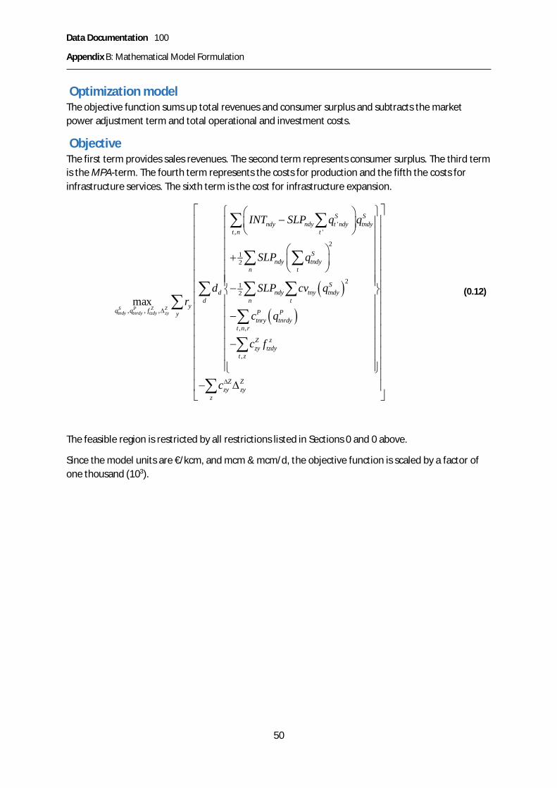
Data Documentation 100
Appendix B: Mathematical Model Formulation
50
Optimization modelThe objective function sums up total revenues and consumer surplus and subtracts the marketpower adjustment term and total operational and investment costs.
ObjectiveThe first term provides sales revenues. The second term represents consumer surplus. The third termis the MPA-term. The fourth term represents the costs for production and the fifth the costs forinfrastructure services. The sixth term is the cost for infrastructure expansion.
( )( )
', '
212
212
, , ,
, ,
,
maxS P Z Ztndy tnrdy tzdy zy
S Sndy ndy t ndy tndy
t n t
Sndy tndy
n t
Sd ndy tny tndy
d n ty
q q f P Pytnry tnrdy
t n r
Z zzy tzdy
t z
zy
INT SLP q q
SLP q
d SLP cv qr
c q
c f
c
D
ì üæ ö-ï ïç ÷è øï ï
ï ïæ öï ï+ ç ÷ï ïè øï ïï ï-í ýï ïï ï-ï ïï ï-ï ïï ïï ïî þ
-
å å
å å
å å åå
å
å
Z Zzy
z
D
é ùê úê úê úê úê úê úê úê úê úê úê úê úê úê úê ú
Dê úë ûå
(0.12)
The feasible region is restricted by all restrictions listed in Sections 0 and 0 above.
Since the model units are €/kcm, and mcm & mcm/d, the objective function is scaled by a factor ofone thousand (103).

Data Documentation 100
Appendix C: Pipeline characteristics
51
Appendix C: Pipeline characteristicsThis Appendix summarizes the economic characteristics such as investment costs as well asoperational costs and losses for pipelines.23
Pipeline construction costs are strongly dependent on local characteristics and vary cyclically. Forexample, steel makes up a large share of the costs and its prices can vary a lot over time.
The pipeline location, if it is onshore or offshore, the terrain that it is crossing (e.g., mountains,marshlands) and the sea depth have a big impact on the economic pipeline characteristics. However,there are no simple relationships between the location and the pipeline characteristics: an “easy”offshore pipe in low sea depth is cheaper than an onshore pipeline in mountainous terrain.
Generally, there is very little data available publicly on economic pipeline characteristics and we hadto make our assumptions based on very few data points. Here we present a range of acceptablevalues. The actual data choices are made during calibration and can be found in Table 6 in Section 0.
Table 41: Overview of pipeline data ranges
Investment cost Operational Losses€/kcm/1000 km /year €/kcm/1000 km /day €/kcm/1000 km / 1000 km
PipelineOnshore 75-200 27375-73000 5-20 2%-3%
Offshore Multiply by two Multiply by two
Pipeline investment costsWe present a very limited number of data points, some rather old (Table 42). Costs are verydependent on local characteristics. When we know that pipelines are offshore, we multiply the costsby the value of parameter BIPipeOffshMult in Table 6). Further pipeline specific adjustments can beadjusting the calibration parameters in data.xlsx.
Table 42: Exemplary data points for pipeline investment costs
Investmentcosts M$
Capbcm
Length(1000 km)
$/kcm/1000 km Comment, source
Medgaz offshore 1000 8 0.21 600Small, deep offshore, unclear ifonshore part included
Nordstream offshore 8000 55 1.224 120Huge, so economies of scale, butoffshore
Large,High onshore 1500 15 1000 100WEO 2001 in Cornot-Gandolphe2003
Large, Low onshore 1000 30 1000 33WEO 2001 in Cornot-Gandolphe2003
BBL offshore € 500 16 230 € 136Not so deep. Capacity up 20%after adding a compressor.
23 This is described in more detail in internal document Pipeline characteristics 20190214.docx

Data Documentation 100
Appendix C: Pipeline characteristics
52
Operational costs and lossesWe take an aggregated view of the gas value chain and focus on the supplier perspective. However,we know that for the supplier the fees to the pipeline TSOs are costs. IFP (2003, p 6) reports that gastransport costs can exceed half of the gas market value (price). Here, “costs” should probably beinterpreted as “tariffs / fees”. We base our assumptions on operational costs of 7-20 € / kcm andlosses of 2% on a limited number of data points reported below.
Table 43: Overview of operational pipeline cost data
Value Region Text SourceRate $ 7 /1,000 m3 /1000 km
Russia Rate in effect since October 1, 2004 RUR 19.37 (approx. $0.70) per 1,000 m3/100 km. {...} rate fails to cover thecosts of upgrading {...}
Gazpromn.d.
€ 11 (perentry / exitfee!)
Europe entry AND exit fee €1/MWh (and costs € 0.1) REKK2017
Same ordermagnitudeas REKK
Entry-Exit tariffs in the order of several to lower doubledigit euros per 1000 m3 (e.g., Fluxys 8-25 €/m3/h/y) x(1000/yearly load hours e.g. 4000): 2-6 x 2 for both entryand exit 4-12
ADL 2004
Table 44: Overview of pipeline loss data
Losses Sources
0.22% /100 km inCzech Republic
18.1.3. The service gas “For a distance of 100 km such service gas is 0.22 % ofthe volume delivered at the entry point for transportation.” European TPATariff Comparison 2003 V3 Page 78 of 100
Literature references for pipeline dataADL 2004, Arthur D Little May 2004, Gas transport services, West European Gas Transmission TariffComparisons.
Cornot-Gandolphe, Sylvie et al. (2003), (Various authors from IEA, IFP, Cedigaz), The challenges offurther cost reductions for new supply options (pipeline, LNG, GTL), 22nd World Gas Conference 1-5June 2003, Tokyo, Japan
Gazprom n.d. http://eng.gazpromquestions.ru/page8.shtml (Accessed July 2007)
REKK 2017 Toth et al. 2017 Follow-up study to the LNG and storage strategy. EUR 2016.4053 EN

Data Documentation 100
Appendix D: LNG value chain characteristics
53
Appendix D: LNG value chain characteristicsThis Appendix summarizes all data related to the LNG value chain, i.e. LNG liquefaction,regasification, and shipping. This includes investment costs as well as operational costs and loss ratesfor liquefaction, regasification and shipping.24
Here we present a range of acceptable values. The actual data choices are made during calibrationand can be found in Table 6 in Section 0.
Table 45: Overview of LNG data ranges
Item Investment Operational Losses€ / kcm / yr € / kcm / d € / kcm
Liquefaction 400-1000 146000-365000 5-30 10%-14%Regasification 90-150 32850-45625 2-20 0.5%-1.5%
/1000 sea miles /1000 sea milesShipping Not represented 5-15 0.25-0.4%
· To get from € / kcm / yr to € / kcm / d multiply by 365· Investment costs for liquefaction have been roughly 3-6 times higher than for regasification· To reflect anticipated cost decreases we can opt for lower end investment cost estimates for
liquefaction, and lower end loss rates and operational costs.
Unit conversion and exchange rateLNG is usually measured in tons of LNG. However, liquefied natural gas has another energy densitythan gaseous natural gas. GGM works with (gaseous) natural gas as standard (homogenous)commodity. Hence a need to convert from LNG tons to cubic meters
We use the following conversion assumptions:
1 ton LNG = 1350 cubic meter natural gas,
1 Mtpa LNG = 1.35 bcm natural gas
This comes from the ranges found in the literature and reported in Table 45
Table 46: Natural gas energy content: overview of literature estimates
kWh mbtuLow 1 cm 10.5 35.8
in GGM 1 cm 11.4 38.9High 1 cm 12 40.9
LNG tends to have higher end energy density than “regular” natural gas due to purification. Since wehave both gaseous and liquefied natural gas we choose to multiply by 40 to convert costs per Mbtuto costs per kcm.
24 More details in internal document LNG_characteristics_20190214.docx
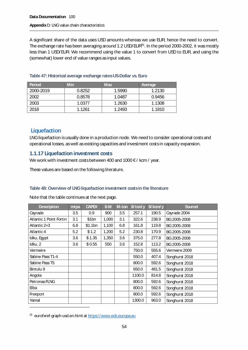
Data Documentation 100
Appendix D: LNG value chain characteristics
54
A significant share of the data uses USD amounts whereas we use EUR, hence the need to convert.The exchange rate has been averaging around 1.2 USD/EUR25. In the period 2000-2002, it was mostlyless than 1 USD/EUR. We recommend using the value 1 to convert from USD to EUR, and using the(somewhat) lower end of value ranges as input values.
Table 47: Historical average exchange rates US-Dollar vs. Euro
Period Min Max Average2000-2019 0.8252 1.5990 1.21302002 0.8578 1.0487 0.94562003 1.0377 1.2630 1.13082018 1.1261 1.2493 1.1810
LiquefactionLNG liquefaction is usually done in a production node. We need to consider operational costs andoperational losses, as well as existing capacities and investment costs in capacity expansion.
1.1.17 Liquefaction investment costsWe work with investment costs between 400 and 1000 € / kcm / year.
These values are based on the following literature.
Table 48: Overview of LNG liquefaction investment costs in the literature
Note that the table continues at the next page.
Description mtpa CAPEX $-M M-ton $/ton/y $/kcm/y SourcetCayrade 3.5 0.9 900 3.5 257.1 190.5 Cayrade 2004Atlantic 1 Point Fortin 3.1 $1bn 1,000 3.1 322.6 238.9 BG 2005-2008Atlantic 2+3 6.8 $1.1bn 1,100 6.8 161.8 119.8 BG 2005-2008Atlantic 4 5.2 $ 1.2 1,200 5.2 230.8 170.9 BG 2005-2008Idku, Egypt 3.6 $ 1.35 1,350 3.6 375.0 277.8 BG 2005-2008Idku, 2 3.6 $ 0.55 550 3.6 152.8 113.2 BG 2005-2008Vermeire 750.0 555.6 Vermeire 2009Sabine Pass T1-4 550.0 407.4 Songhurst 2018Sabine Pass T5 800.0 592.6 Songhurst 2018Bintulu 9 650.0 481.5 Songhurst 2018Angola 1100.0 814.8 Songhurst 2018Petronas FLNG 800.0 592.6 Songhurst 2018Elba 800.0 592.6 Songhurst 2018Freeport 800.0 592.6 Songhurst 2018Yamal 1300.0 963.0 Songhurst 2018
25 eurofxref-graph-usd.en.html at https://www.ecb.europa.eu

Data Documentation 100
Appendix D: LNG value chain characteristics
55
Gladstone 1300.0 963.0 Songhurst 2018Pacific FLNG 1300.0 963.0 Songhurst 2018Prelude FLNG 2000.0 1481.5 Songhurst 2018Gorgon 2100.0 1555.6 Songhurst 2018Liquefaction-low 600.0 444.4 Songhurst 2018Liquefaction-high 1400.0 1037.0 Songhurst 2018Mid 1990s 340 251.9 IEA WEIO p. 202, Fig 5.102002 260 192.6 IEA WEIO p. 202, Fig 5.102010 - estimate 200 148.1 IEA WEIO p. 202, Fig 5.102030 - estimate 160 118.5 IEA WEIO p. 202, Fig 5.10
The literature (Vermeire, 2009) also reports that liquefaction investments costs are 6.25 times asexpensive as regasification investment costs at $90/kcm/y. Considering losses, one may round downto 6. Cayrade mentions a ratio of 3 of investment costs in liquefaction vs. regasification. Vermeire(2009) estimates are at the lower end of the more recent Songhurst (2018) estimates.
1.1.18 Liquefaction operational costs and lossesWe assume operational costs between 15 and 30 € / kcm and a loss rate between 10 and 14%. This isbased on the literature mentioned in the following table.
Table 49: Overview of estimates of LNG liquefaction operational costs in the literature
$/Mbtu €/kcm Comment Source0.8 30 lower end, price-based: much higher than operat costs IELE 2003, p. 161.2 50 higher end, price-based IELE 2003, p. 16
0.93 35 Egypt, Levelized, price based, Fig 5.31 IEA 2003 p. 2630.97 40 Trinidad IEA 2003 p. 2631.02 40 Nigeria IEA 2003 p. 2631.10 45 Qatar IEA 2003 p. 2631.37 55 Venezuela – higher end, read from Fig 5.31 IEA 2003 p. 263

Data Documentation 100
Appendix D: LNG value chain characteristics
56
Table 50: Overview of estimates of LNG liquefaction operational losses in the literature
Value Comment Source12% On average 12% (…) used to fuel the liquefaction process. Gaz de France –2004
10.3% Natural gas consumption IGU emissions from gas sector
Regasification1.1.19 Regasification investment costsWe assume investment costs in LNG regasification capacity between 90 and 125 € / kcm / year. Thisis based on the estimates from the literature.
Table 51: Overview of LNG regasification investment cost estimates in the literature
Description CAPEX M-$ mtpa $/ton/y $/kcm/y Source
Dragon LNG £250 mio 425 4.4 96.6 71.5 BG 2005500 4.4 113.6 84.2 Different exchange rate
Brindisi 2005 €390 mio 400 6 66.7 49.4 BG 2005500 6 83.3 61.7 Different exchange rate
Brindisi 2008 €500 mio 500 6 83.3 61.7 BG 2008750 6 125.0 92.6 With 1.5 exchange rate
Vermeire 90 Vermeire 2009Mid 1990s 150 110 IEA WEIO p. 202 Fig 5.102002 140 100 IEA WEIO p. 2022010 - estimate 130 100 IEA WEIO p. 2022030 - estimate 90 65 IEA WEIO p. 202GermanyWilhelmshavenonshore
€1500 M 7.5-10 105-150 Deutsche Flüssiggas TerminalGmbH
GermanyWilhelmshavenFSRU
€ 10 M +several ten M€ for the FSR
unit
6bcm(?)
Much lowerorder of
magnitude
Nord-West Ölleitung (NWO)FSRU + lot of onshoreinfrastructure already in place.
Germany – Stade €400 - 500 M 3 100-125
Note: 1 ton LNG is approximately 1350 cm
1.1.20 Regasification operational costs and lossesWe assume operational costs of LNG regasification of 2 to 20 € / kcm as well as loss rates between0.5% and 1.5%). This is based on the following estimates from the literature.
Table 52: Overview of estimates of regasification operational costs in the literature
Description Original value EUR /kcm
Comment Source
lower end $ 0.3 / MMbtu 10 2002, price-based, higher thanoperational costs
IELE 2003, p. 16
higher end $ 0.5 / MMbtu 20 2002, price-based, higher thanoperational costs
IELE 2003, p. 16

Data Documentation 100
Appendix D: LNG value chain characteristics
57
Fig 5.31 0.5 20 Read from Fig 5.31 IEA 2003 p. 263Lake Charles 27.34c / mmbtu 11 Fixed operation BG 2005Lake Charles 2.99c / mmbtu 1.2 Variable operation BG 2005Lake Charles 12 Blended BG 2005Lake Charles low 0.20s / mmBtu 8-9 Blended BG 2006, BG 2008Elba Island 21c/mmbtu 8 Fixed operation BG 2005Elba 4.5c/mmbtu 2 Variable operation BG 2005Elba 10 Blended BG 2005
The following table gives account of the – very few – estimates of the loss rates associated withregasification. According to BG 2005, the lower operational cost facility has higher loss rate.
Table 53: Overview of loss rate estimates in the literature for LNG regasification
Value Comment Source0.43% LNG regasification - Natural gas consumption: Energy IGU emissions from gas sector1.66% Lake Charles BG 20051.2% Elba Island BG 2005
LNG ShippingWe include shipping with the operational costs associated with it. These costs are distance-related.
However, we do not properly represent the freight market with shipping fees resulting from supply-demand equilibrium for freight services. We also do not include the investment perspective in newships which is subject to dynamics that a gas-sector-only model can hardly represent.
We calculate shipping distances with the help of the following sources:
· www.distances.com· https://sea-distances.org/· National imagery and mapping agency 2001, PUB. 151, Distances between ports, 11th edition· GIIGNL annual report, see https://giignl.org/
In case there is more than one LNG terminal in a country, there usually is a representative onechosen for the location of the LNG node. We aggregate all LNG capacities located in the samecountry or region and attribute the total capacity to the representative terminal location.For new LNG terminal projects in countries with LNG yet, we chose a port location among existingports to calculate the distances.
1.1.21 LNG shipping costs and lossesWe assume shipping costs in the range 5-15 € / kcm / 1000 sea miles. Moreover, we assume lossesbetween 0.25 and 0.4 % per 1000 sea miles.
We abstract from economies of scale and use average distance-related costs. However, we knowthat large ships such as ships of the Q-max category have significant economies of scale. Forexample, in December 2008, ExxonMobil reported that it’s then largest LNG carrier in the world witha capacity up to 266,000 cubic meters (up to 80 percent more cargo than conventional LNG ships)requires approximately 40 percent less energy per unit of cargo than conventional LNG carriers dueto economies of scale and efficiency.

Data Documentation 100
Appendix D: LNG value chain characteristics
58
Table 54: Overview of LNG shipping cost estimates in the literature
Shipping$/Mbtu
Approximate distancein sea miles
Source Processcalculation
€/kcm/ 1000sea miles
Trinidad 0.30 $/Mbtu 2,100 IEA 2003 WEIO 0.3x40/2 6Nigeria 0.72 $/Mbtu 4,000 IEA 2003 0.7x40/4 7Venezuela 0.27 $/Mbtu 1,700 IEA 2003 0.27x40/1.7 6Egypt 0.70 $/Mbtu 5,500 IEA 2003 0.7x40/5.5 5Qatar 1.23 $/Mbtu 9,000 IEA 2003 1.23x40/9 5.5Several DOE EIA 2003 6-7IELE 0.000171 $/MMBtu/mile IELE 2003 p 10, Fig x40x1000 7Lopak
8.75 $/kcm/1000 sea milesLopak 2008 + own
correctionsSee below 8
Note: the table reports the estimated costs and distance to the U.S. Gulf coast. Located along the US Gulf Coastare the U.S. States of Texas, Louisiana, Mississippi, Alabama, and Florida. These are the U.S.Censes (and GGM)regions 5, 6,and 7.
Note: IEA 2003 WEIO numbers are from p 263 and give levelized costs in $/Mbtu.
1.1.21.1 Lopak 2008Lopak provides an insightful overview of the details of LNG shipping costs. However, it seems thatthe author does not account for the empty return trip (possibly in fuel costs, but not in othercalculations).
Lopak Per 1000sea miles
Crew, O&M, admin 17,764 /day 39,000Speed 19 knots 456 sea miles / dFuel 160 ton/day When sailingBunker fuel 500 $/ton may be -50% / +100% 160x500x2.2= 176,000
3 ton/day When (un)loading Not includedloading One day Fixedunloading Two days Fixed
Lopak DOE EIA 2003 -p 52Charter rates 55,000-60,000 contracts $55,000 - $65,000.
60,000x2.2 132,00070,000+ spot $27,000 -$150,000.
Total, one.way 350,000
§ 138,000 m3 x 23.3 Mbtu/m3 = 3.2 M Mbtu = 0.08 M kcm§ Empty return trip: 2 x ($ 350,000 / 80,000 kcm) = 70/8 = $ 8.75 / kcm / 1000 sea miles§ This does NOT account for loading and unloading days§ This can be 50% lower or double as high in specific case
1.1.21.2 DOE EIA 2003We divide the shipping rates presented in DOE (2003), see Table 55 by estimated distances (Table56) to obtain costs per unit of energy per unit of distance (Table 57).
Table 55 Shipping Rates ($/MBtu)
Everett Cove Point Elba Island Lake Charles

Data Documentation 100
Appendix D: LNG value chain characteristics
59
Boston Maryland Georgia LouisianaRegion 1 Region 5 Region 5 Region 7
Algeria 0.52 0.57 0.6 0.72Australia 1.76 1.82 1.84 1.84Nigeria 0.8 0.83 0.84 0.93Norway 0.56 0.61 0.64 0.77Qatar 1.37 1.43 1.46 1.58Trinidad & Tobago 0.35 0.35 0.32 0.38Venezuela 0.34 0.33 0.3 0.35
Distances from our own database:
Table 56: Distances for these LNG trade relations in the GGM database (in 1000 sea miles)
Region 1 Region 5 Region 7Algeria 3.5 3.8 5.0Australia 11.2 11.1 10.6Nigeria 4.6 5.3 4.0Norway 3.5 3.9 5.0Qatar 8.1 8.5 9.5Trinidad & Tobago 1.9 1.9 2.1Venezuela 1.9 1.8 1.7
Resulting costs by dividing values in the previous two tables, and multiplying by 40:
§ Algeria-Region 1: 0.52*40 (Mbtu/kcm)/3.5= 5.9; (at 38 (Mbtu/kcm): 5.6)§ Australia-Region 1: 1.76*40 (Mbtu/kcm)/11.2= 6.3; (at 38 (Mbtu/kcm): 6.0)
Table 57: Calculated estimates for LNG shipping costs ($ / kcm / 1000 sea miles)
Region 1 Region 5 Region 5 Region 7Algeria 5.9 6.0 6.3 5.8Australia 6.3 6.6 6.6 6.9Nigeria 7.0 6.3 6.3 9.3Norway 6.4 6.3 6.6 6.2Qatar 6.8 6.7 6.9 6.7Trinidad & Tobago 7.4 7.4 6.7 7.2Venezuela 7.2 7.3 6.7 8.2
Table 58: Overview of loss estimates of LNG shipping in the literature (boil off per 1000 sea miles)
Value Comment Source
0.35-0.4% 0.21% LNG transport (BAT – Best available technology, 1000km) - Natural gas consumption – Energy
IGU emissions fromgas sector

Data Documentation 100
Appendix D: LNG value chain characteristics
60
0.2-0.35% 0.1-0.15% for larger ships (up to 0.25% for small ships) per day Lopak 2008
LNG value chain literature sourcesWe refer to the following sources for LNG data:
§ BG Group 2005 LNG Fact Sheets§ BG Group 2006, A market leader in Global LNG, The Houstonian, 11 Sept 2006, Presentation§ BG Group 2008 LNG Fact Sheets§ Cayrade, Patrick 2004 Investments in Gas Pipelines and Liquefied Natural Gas Infrastructure.
What is the Impact on the Security of Supply? NOTA DI LAVORO 114.2004, September 2004§ EIA DOE 2003, Energy Information Administration, U.S. Department of Energy, The Global
Liquefied Natural Gas Market - Status & Outlook, December 2003, DOE/EIA-0637 (2003)§ GdF 2004, Gaz de France, European leader in Liquefied Natural Gas (LNG), July 2004§ IEA 2003 WEIO World Energy Investment Outlook OECD/IEA, 2003§ IELE 2003 University of Houston, Institute for Energy, Law & Enterprise. Introduction to LNG,
An overview on liquefied natural gas (LNG), Its properties, the LNG industry, safetyConsiderations, January 2003
§ IGU International Gas Union, emissions from gas sector§ Lopac, Andreja Ana 2008 Recent trends in transporting of lng, liquefied natural gas§ Songhurst, Brian 2018 LNG Plant Cost Reduction 2014–18, Oxford Institute for Energy
Studies, OIES PAPER: NG137, October 2018§ Vermeire; Jean 2009, (President GIIGNL), global dynamics of LNG business, GIE annual
Conference, Groningen, Netherlands, 6-7 MAY 2009

Data Documentation 100
Appendix E: Storage characteristics
61
Appendix E: Storage characteristicsThis Appendix lists and summarizes storage characteristics.26 We include seasonal gas storage –which is mostly underground gas storage – in the model database. For some countries, we alsoinclude LNG storage (in particular Japan and South Korea).
We distinguish several activities / commodities related to gas storage: injection into storage facilitiesand extraction (EXTR) from storage facilities, as well as working gas (WG) which is the volume of gasin storage that can actually be retrieved. We assume that storage facilities are empty at thebeginning of the year and at the end of the year. In other words, everything that is injected in oneseason is extracted in the other season (“storage cycle constraint”).
Several types of geological (underground) storage facilities exist. Seasonal and long-term (strategic)storage generally uses depleted (oil and gas) fields and aquifers. Short cycle storage for dailychurning as well as backup storage by the distribution sector is often using salt caverns but also LNGpeak storage (the latter is generally not underground but often a unit in a regasification terminal).
We include the following data in the model data base:
o investment cost (incl. cushion gas)o operational and maintenance costo loss rates
Here we present a range of acceptable values. The actual data choices are made during calibrationand can be found in Table 6 in Section 0.
Table 59: Overview of storage data ranges
Investment cost Operational Losses€/kcm €/kcm/day
SeasonalWG 150-500 N.A.
EXTR 1258-70000 20-60 (Inj+Extr) 0.5%-1.5%Peak Too expensive 40LNG
WG As regasifier N.A. As regasifier (1.5%)EXTR For free Very low
Construction costs of storage facilities depend strongly on local characteristics and behave verycyclically. This is largely due to the fact that cushion gas makes up a large share of the investmentcosts and natural gas prices vary a lot over time.For peak shavers (salt caverns and LNG peak storage), we include existing capacities but ignoreexpansion.For LNG terminal storage in Japan and S. Korea, we assume that storage injection and extraction istaking place at the regasification terminals. In this case, working gas capacity expansion possible atsame cost as regasification capacity.
26 This is based on document storage_characterists_20190206_v0_RE.docx