data format control document (dfcd) … · 2.3.2 label subfields ... 3–121 3–10a polar orbit...
TRANSCRIPT
560-1DFD/0190CSC/TR-91/6014
DATA FORMAT CONTROL DOCUMENT(DFCD) BETWEEN THE
INTERNATIONAL SOLAR-TERRESTRIALPHYSICS (ISTP) PROGRAM
MISSION OPERATIONS AND SYSTEMSDEVELOPMENT DIVISION (MOSDD) GROUNDDATA PROCESSING SYSTEM AND THE ISTP
MISSION INVESTIGATORS
REVISION 2
MAY 1996
National Aeronautics andSpace Administration
Goddard Space Flight Center Greenbelt, Maryland

30001170M
560-1DFD/0190CSC/TR-91/6014
Data Format Control Document (DFCD) Between theInternational Solar-Terrestrial Physics (ISTP) ProgramMission Operations and Systems Development Division
(MOSDD) Ground Data Processing Systemand the ISTP Mission Investigators
Revision 2
Prepared for
MISSION OPERATIONS AND SYSTEMS DEVELOPMENT DIVISIONNational Aeronautics and Space Administration
Goddard Space Flight CenterGreenbelt, Maryland 20771
By
COMPUTER SCIENCES CORPORATIONSystem Sciences Division
7700 Hubble DriveLanham-Seabrook, Maryland 20706
May 1996

560-1DFD/0190CSC/TR-91/6014
Data Format Control Document (DFCD) Between theInternational Solar-Terrestrial Physics (ISTP) ProgramMission Operations and Systems Development Division
(MOSDD) Ground Data Processing Systemand the ISTP Mission Investigators
Revision 2
Prepared by: Computer Sciences CorporationSEAS Contract NAS5–31000Subcontract HQ-001057
Approved by: W. Mish, Code 694 DateISTP Deputy Project Scientist for Data Systems
S. Sekira, Code 514.1 DateISTP CDHF Project Manager
J. Shirley, Code 514.1 DateMOSDD DDF Project Manager

v
LIST OF EFFECTIVE PAGES
____________________________________________________________________________________________
All

vii
DCN CONTROL SHEET
____________________________________________________________________________________________
Use this control sheet to record the DCN changes to this document.
DCN No. DTG Mon/Yr Sect. Initials
___________ ___________ __________ __________ ____________
___________ ___________ __________ __________ ____________
___________ ___________ __________ __________ ____________
___________ ___________ __________ __________ ____________
___________ ___________ __________ __________ ____________
___________ ___________ __________ __________ ____________
___________ ___________ __________ __________ ____________
___________ ___________ __________ __________ ____________
___________ ___________ __________ __________ ____________
___________ ___________ __________ __________ ____________
___________ ___________ __________ __________ ____________
___________ ___________ __________ __________ ____________
___________ ___________ __________ __________ ____________
___________ ___________ __________ __________ ____________
___________ ___________ __________ __________ ____________
___________ ___________ __________ __________ ____________
___________ ___________ __________ __________ ____________

ix
ABSTRACT
____________________________________________________________________________________________
This data format control document (DFCD) defines the formats of the data provided to theInternational Solar-Terrestrial Physics (ISTP) program mission investigators by the ISTP CentralData Handling Facility (CDHF) and the Mission Operations and Systems Development Division(MOSDD) Data Distribution Facility (DDF). The ISTP mission investigators are thoseinvestigators responsible for an experiment onboard the ISTP spacecraft, as well as ground-basedand theory investigators. The ISTP CDHF and the MOSDD DDF are elements of the ISTPGround Data Processing System (GDPS) at the National Aeronautics and Space Administration(NASA) Goddard Space Flight Center (GSFC). The ISTP CDHF is an ISTP project-fundedfacility that provides instrument data processing and data access support for ISTP missions. TheDDF is an MOSDD institutional facility that sends the data on physical media to the scientificinvestigators.
A detached ISTP standard formatted data unit (SFDU) header is associated with ISTP CDHFmanaged data files. The National Space Science Data Center’s (NSSDC’s) common data format(CDF) is used for key parameter, orbit, and attitude data.
To date, key parameter formats have been very dynamic. As a result, they have been removedtemporarily from this document.
The WIND level-zero, housekeeping, and quality and accounting tables in this document reflectthe Command and Telemetry Handbook, WIND, Revision 3.2, September 1, 1993 (Reference 8).The POLAR level-zero, housekeeping, and quality and accounting tables in this document reflectthe POLAR Command and Telemetry Handbook, Revision 3.1, January 15, 1995 (Reference 9).
The formats of SOHO orbit and attitude, including the full-time resolution attitude, data files aredocumented in Sections 3.6 and 3.7 of this DFCD. No other SOHO data formats are documentedhere. The formats of the SOHO telemetry packets, including level-zero and housekeeping dataare defined in Section 10 of the Interface Control Document Between the Sensor DataProcessing Facility (SDPF) and the Solar and Heliospheric Observatory (SOHO) Consumers(Reference 12).
SOHO data filenames conform to either the ISTP CDHF or the MOSDD Packet Processor DataCapture Facility II (Pacor II) file-naming conventions, as applicable. The two conventions, andinformation on which SOHO files conform to which convention, are described in Appendix D,Section D.1. In addition, the ISTP CDHF SFDU header and the Pacor II SFDU are describedthere.
This revision provides updated orbit and attitude formats and updated ISTP compact disc–read-only memory (CD-ROM) directory structure.
The POLAR wideband data formats have been added as Appendix E. The data formats from theCDHF Near Real Time (NRT) Server are described in Appendix F.
In Section 3.3.3.3 (POLAR Spacecraft Housekeeping Data Record and Subrecord Formats), thenumber of the byte containing the POLAR Magnetic Field Investigation (MFE) magnetometerMNTSCALE value has been corrected.
The information in this document reflects Release 6.2 of the ISTP CDHF software andRelease 3.2.1 of the MOSDD DDF software.

x
Computer Sciences Corporation (CSC) is responsible for maintaining this document. Please sendall additions, corrections, or questions to ISTP::USER_DOC.

xi
CONTENTS
____________________________________________________________________________________________
Section 1—Introduction1.1 Purpose ............................................................................................................................ 1–11.2 Scope ............................................................................................................................... 1–11.3 Intended Users................................................................................................................. 1–21.4 Documentation Precedence ............................................................................................. 1–21.5 ISTP Scientific Investigator Community ........................................................................ 1–41.6 Document Organization .................................................................................................. 1–41.7 Overview of Interface ..................................................................................................... 1–7
Section 2—ISTP Data Format Overview2.1 Background and Scope.................................................................................................... 2–12.2 ISTP Data Format Overview........................................................................................... 2–2
2.2.1 ISTP Data Format Requirements ..................................................................... 2–22.2.2 SFDU Standard for ISTP Data Formats........................................................... 2–32.2.3 SFDU Concepts................................................................................................ 2–3
2.3 SFDU Structure ............................................................................................................... 2–42.3.1 SFDU Structure—Basic ................................................................................... 2–52.3.2 Label Subfields ................................................................................................ 2–52.3.3 Value Field ....................................................................................................... 2–92.3.4 SFDU Structure—Nested................................................................................. 2–9
2.4 SFDU in the ISTP CDHF.............................................................................................. 2–102.4.1 CDHF SFDU Structure .................................................................................. 2–112.4.2 Parameters in the CIO .................................................................................... 2–112.4.3 Parameters in the Reference Object ............................................................... 2–16
2.5 SFDU Example for ISTP .............................................................................................. 2–172.6 File-Naming Conventions ............................................................................................. 2–182.7 Common Data Format................................................................................................... 2–25
2.7.1 CDF Data ....................................................................................................... 2–252.7.2 CDF Attributes ............................................................................................... 2–272.7.3 CDF Software Library ................................................................................... 2–272.7.4 CDF Tools ...................................................................................................... 2–292.7.5 Sample CDF Skeleton .................................................................................... 2–31
2.8 ISTP Key Parameters .................................................................................................... 2–31Section 3—ISTP Data File Formats
3.1 Level-Zero Data Format.................................................................................................. 3–13.1.1 Level-Zero Data File Label Record ................................................................. 3–23.1.2 Level-Zero Data Record Header .................................................................... 3–123.1.3 Level-Zero Data Subrecord Formats.............................................................. 3–15
xii
3.2 Q/A File Formats .......................................................................................................... 3–913.3 Housekeeping Data Format........................................................................................... 3–97
3.3.1 Housekeeping Data File Label Record .......................................................... 3–993.3.2 Housekeeping Data Subrecord Formats......................................................... 3–993.3.3 Housekeeping Data Record and Subrecord Formats ..................................... 3–99
3.4 SIRIUS Data Format ................................................................................................... 3–1083.5 Command History Format .......................................................................................... 3–116
3.5.1 GEOTAIL Command History Format ......................................................... 3–1163.6 Orbit Formats .............................................................................................................. 3–1203.7 Attitude Formats ......................................................................................................... 3–1203.8 SOHO Full-Time Resolution Attitude ........................................................................ 3–1633.9 GEOTAIL Spin-Phase Format .................................................................................... 3–1633.10 WIND and POLAR Spin-Phase Format ..................................................................... 3–163
Appendix A—Level-Zero File Sizes
Appendix B—Key Parameter Volumes
Appendix C—Extended Minor Frames
Appendix D—File-Naming Conventions,CD-ROM Volume Identifier, Volume Description and
Index Files, and Directory Structure
Appendix E—POLAR Wideband Data Formats
Appendix F—Near Real Time Server Data
List of Acronyms
References
_____________________________________________
List of Figures2–1 Data Product.................................................................................................................... 2–42–2 Label-Value-Object (LVO) Structure ............................................................................. 2–52–3 SFDU Label .................................................................................................................... 2–62–4 Nested LV Object (SFDU)............................................................................................ 2–102–5 ISTP SFDU Example .................................................................................................... 2–18

xiii
3–1 Level-Zero Data File Format .......................................................................................... 3–23–2 GEOTAIL Telemetry Format for Major Frame............................................................ 3–163–3 WIND Major Frame Telemetry Format ........................................................................ 3–283–4 POLAR Major Frame Telemetry Format...................................................................... 3–503–5 Housekeeping Data File Format ................................................................................... 3–983-6 Code To Extract MFE Magnetometer Data From POLAR Housekeeping Data
File .............................................................................................................................. 3–1053–7 SIRIUS Data Format for Telemetry Playback Data.................................................... 3–1093–8 Message Data Part of SIRIUS Data File ..................................................................... 3–109
List of Tables1–1 Supplemental ICDs ......................................................................................................... 1–21–2 ISTP Mission Experiments ............................................................................................. 1–41–3 ISTP Ground-Based, Theory, and Other Investigations ................................................. 1–62–1 Label Subfields ............................................................................................................... 2–72–2 Length Representation With Respect to Version Value ................................................. 2–82–3 Delimitation Parameters.................................................................................................. 2–92–4 Example CDF—“Flat” Representation ......................................................................... 2–262–5 Example CDF—Two-Dimensional Representation...................................................... 2–272–6 Example CDF—Specification for Two-Dimensional Representation .......................... 2–272–7 Standard NSSDC CDF Attributes ................................................................................. 2–282–8 Time Variable Attributes .............................................................................................. 2–292–9 Key Parameters Standards and Conventions ................................................................ 2–313–1 Level-Zero Data File Label Record Definition ............................................................... 3–23–2 Data Record Header Definition..................................................................................... 3–123–3 Q/A Label Record Definition........................................................................................ 3–923–4 Q/A Data Record Format .............................................................................................. 3–943–5 Major Frame Q/A Entry Format ................................................................................... 3–953–6 SIRIUS Telemetry Data Record ................................................................................. 3–1103–7 GEOTAIL Frame Quality Indicators Format.............................................................. 3–1113–8 Control Block for SIRIUS Data .................................................................................. 3–1113–9 GEOTAIL Command History File Configuration ...................................................... 3–1163–10 ISTP Orbit CDF .......................................................................................................... 3–1213–10a POLAR Orbit Variables .............................................................................................. 3–1323–11 ISTP GEOTAIL, WIND, and POLAR Attitude Spin-Stabilized CDF....................... 3–1363–12 ISTP SOHO Attitude CDF.......................................................................................... 3–1433–13 ISTP POLAR Despun Platform Attitude CDF ........................................................... 3–1563–14 SOHO Full-Time Resolution Attitude Data Format ................................................... 3–1653-14a SOHO Full-Time Resolution Attitude Data Record Format....................................... 3-1653–15 ISTP GEOTAIL Spin-Phase CDF .............................................................................. 3–1663–16 ISTP WIND and POLAR Spin-Phase CDF ................................................................ 3–170

1–1
SECTION 1—INTRODUCTION
____________________________________________________________________________________________
1 .1 Purpose
This data format control document (DFCD) defines and describes the formats of the mission dataitems made available or transferred from the International Solar-Terrestrial Physics (ISTP) programCentral Data Handling Facility (CDHF) and the Mission Operations and Systems DevelopmentDivision (MOSDD) Data Distribution Facility (DDF) to the individual ISTP investigators, eitherelectronically or on physical media.
Throughout the remainder of this DFCD, the ISTP CDHF is abbreviated to the CDHF and theMOSDD DDF is abbreviated to the DDF.
The source requirements for this interface are derived from the ISTP Data Processing Segment(DPS) System Requirements Specification (Reference 1).
1 .2 Scope
This DFCD contains detailed descriptions of the data formats applicable to the Geomagnetic TailLaboratory (GEOTAIL), Interplanetary Physics Laboratory (WIND), and Polar Plasma Laboratory(POLAR) missions of the ISTP program. The scope of this DFCD includes the detailedspecification of the data formats used in support of the interface provided by all parties. Thisdocument does not include the description of the SOHO level-zero (LZ) data, which are describedin the Interface Control Document between the Sensor Data Processing Facility (SDPF) and theSolar and Heliospheric Observatory (SOHO) Consumers (Reference 12). The formats of theSOHO summary, command history, time correlation file (TCF) and SOHO daily report (SDR) dataalso are not provided in this document. They can be obtained from the SOHO Experimenters’Operations Facility (EOF).
This DFCD is a configuration-controlled document and, with several other documents, forms theISTP project baseline. This DFCD takes effect upon approval by the ISTP Deputy Project Scientistfor Data Systems, Code 694, the ISTP CDHF Project Manager, Code 514.1, and the MOSDDDDF Project Manager, Code 514.1. Proposed changes to this DFCD require the same level ofapproval.
The format and content of this DFCD comply with the ISTP project-approved guidelines forinterface control documents (ICDs). The ICD guidelines recommend documenting the formatinformation usually found in separate ICDs in one composite document (this DFCD) to reduceredundancy and ease maintainability, thus reducing costs and facilitating the assurance of accuracy.Therefore, the detailed information describing the formats of the ISTP data items provided to theindividual investigations by the CDHF and the DDF has been moved from the individual ICDs tothis document.
This DFCD also defines and describes the formats of the files transferred from the MOSDDGeneric Time-Division Multiplexed (GTDM) Data Capture Facility (DCF) to the ISTP CDHF,from the ISTP CDHF to the MOSDD DDF, and from the MOSDD GTDM DCF to the MOSDDDDF because the formats of these files are essentially the same as those provided to the ISTPmission investigators by the ISTP CDHF and the MOSDD DDF. Documenting the file formats injust one document (i.e., this DFCD) further reduces document redundancy and facilitates document

1–2
maintainability. Formats of files not transferred to investigators are not documented in thisdocument.
1 .3 Intended Users
This document specifies the interface data formats at the level of detail needed by users on eitherside of the interface to proceed with independent system development. This document contains thelayouts and contents of the data files (level-zero, orbit, and attitude) used by the key parametergeneration software (KPGS) of the mission investigators, as well as the key parameters.
1 .4 Documentation Precedence
This document supplements the ISTP project ICDs. These ICDs contain details of the interfaceneeded by the implementers. Where any conflict exists between this document and an ICD, theICD takes precedence over the generalized DFCD. The ICDs listed in Table 1–1 are supplementedby this document. The ICDs listed below contain details of the interface between the CDHF, theDDF, and the ISTP principal investigators (PIs), co-investigators (Co-Is), ground-basedinvestigators (GBIs), and theory investigators (TIs).
Table 1–1. Supplemental ICDs (1 of 2)
ICD Number ICD Name (Note 1) Draft Status
560-1ICD/0489 CDHF/DDF-NSSDC August 94 Final
560-1ICD/0589 CDHF-SPOF April 93 Final
560-1ICD/0190 CDHF/DDF-DARN GBI May 96 Final
560-1ICD/0290 CDHF/DDF-SESAME GBI December 94 Final
560-1ICD/0390 CDHF/DDF-CANOPUS GBI February 95 Final
560-1ICD/0490 CDHF/DDF-SONDRESTROM GBI December 92 Final
560-1ICD/0590 CDHF/DDF-TI IMC April 90 Review Draft
560-1ICD/0690 CDHF/DDF-TI SWMC April 90 Review Draft
560-1ICD/0790 CDHF/DDF-TI TED April 90 Review Draft
560-1ICD/0890 CDHF/DDF-TI SS April 90 Review Draft
560-1ICD/0990 CDHF/DDF-EPACT PI (W) December 94 Final
560-1ICD/1090 CDHF/DDF-KONUS PI (W) December 94 Final
560-1ICD/1190 CDHF/DDF-3DPA PI (W) December 94 Final
560-1ICD/1290 CDHF/DDF-MFI PI (W) April 95 Final
560-1ICD/1390 CDHF/DDF-FDF, Revision 1 April 95 Final
560-1ICD/1490 CDHF/DDF-CAMMICE PI (P) July 95 Sign Off
560-1ICD/1590 CDHF/DDF-CEPPAD PI (P) July 95 Sign Off

1–3
Table 1–1. Supplemental ICDs (2 of 2)
ICD Number ICD Name (Note 1) Draft Status
560-1ICD/1690 CDHF/DDF-EFI PI (P) May 96 Final
560-1ICD/1790 CDHF/DDF-HYDRA PI (P) July 95 Sign Off
560-1ICD/1890 CDHF/DDF-WAVES PI (W) February 95 Final
560-1ICD/1990 CDHF/DDF-TGRS PI (W) March 94 Final
560-1ICD/2090 CDHF/DDF-SWE PI (W) January 95 Final
560-1ICD/2190 CDHF/DDF-SMS PI (W) December 94 Final
560-1ICD/2290 CDHF/DDF-MGF Co-I (G) August 92 Final
560-1ICD/2390 CDHF/DDF-EFD Co-I (G) August 92 Final
560-1ICD/2490 CDHF/DDF-PWI Co-I (G) August 92 Final
560-1ICD/2590 CDHF/DDF-MFE PI (P) May 96 Final
560-1ICD/2690 CDHF/DDF-PIXIE PI (P) April 96 Final
560-1ICD/2790 CDHF/DDF-PWI PI (P) March 96 Final
560-1ICD/2890 CDHF/DDF-TIDE PI (P) May 96 Sign Off
560-1ICD/2990 CDHF/DDF-TIMAS PI (P) March 96 Final
560-1ICD/3090 CDHF/DDF-UVI PI (P) October 95 Final
560-1ICD/3190 CDHF/DDF-VIS PI (P) April 96 Final
560-1ICD/3290 CDHF/DDF-CPI PI (G) August 92 Final
560-1ICD/3390 CDHF/DDF-EPIC PI (G) August 92 Final
560-1ICD/3490 CDHF-GDCF-DDF June 93 Final
560-1ICD/0191 ISAS GSFC IPD (G) September 92 Final
560-1ICD/0441 CDHF-CMS May 93 Final
560-1ICD/0193 CDHF/DDF-WIND Investigators January 96 Final
560-1ICD/0293 CDHF/DDF-POLAR Investigators April 93 Review
560-1ICD/1093 CDHF-SOHO EOF August 94 Final
560-1ICD/0194 CDHF-ERNE PI (S) May 96 Sign Off
560-1ICD/0294 CDHF/DDF-CELIAS PI (S) May 96 Sign Off
560-1ICD/0394 CDHF-COSTEP PI (S) July 94 Sign Off
560-1ICD/0494 CDHF/DDF-CELIAS/CEPAC PI (S) May 96 Sign Off
514-1ICD/0195 CDHF/DDF-SEPS (P) May 96 Sign Off
514-1ICD/0295 CDHF/DDF-GOLF, VIRGO, MDI, SUMER,CDS, LASCO, EIT, UVCS, SWAN PIs (S)
January 96 Sign Off
Notes: 1. Interface names are shown on either side of the hyphen (-). Systems composing oneside of an interface are separated by a slash(/).
2. Spacecraft indicator: (G) = GEOTAIL, (W) = WIND, (P) = POLAR, (S) = SOHO.
1–4
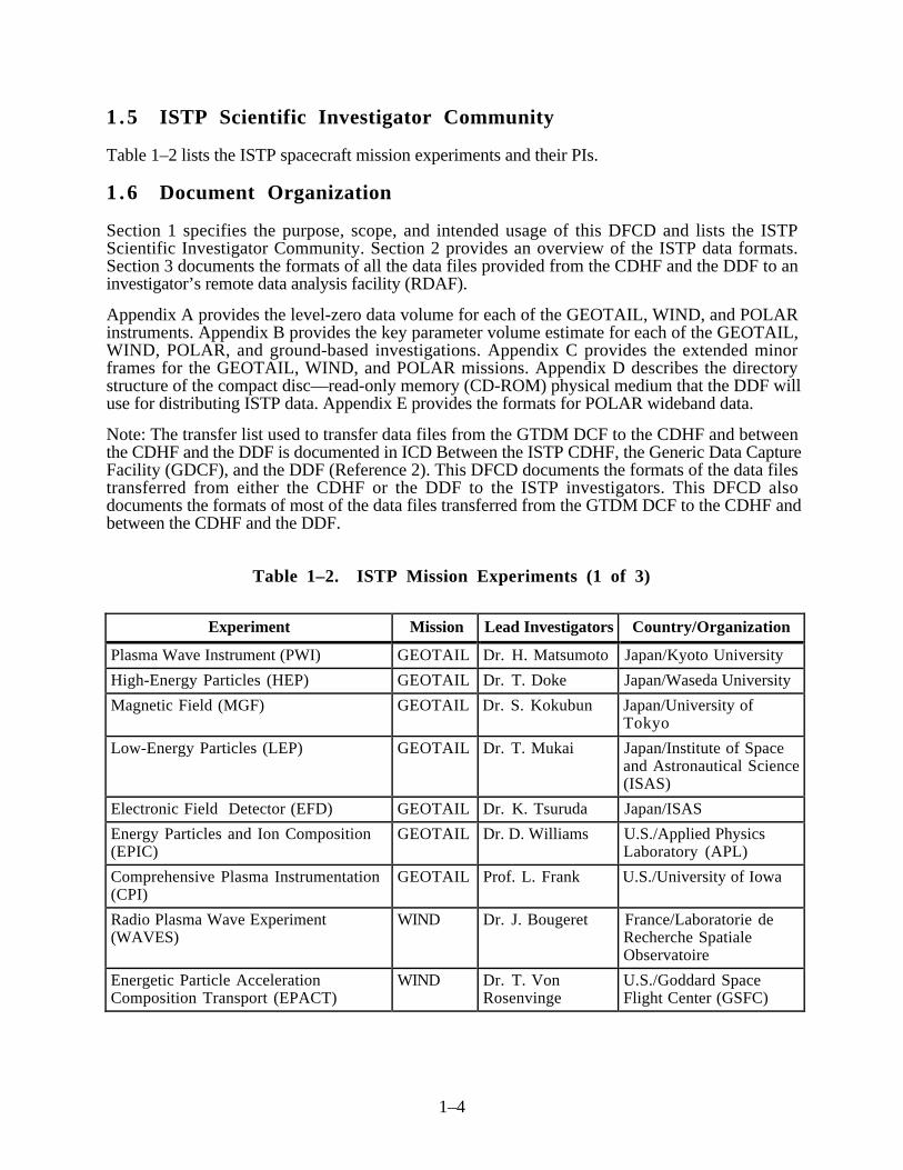
1 .5 ISTP Scientific Investigator Community
Table 1–2 lists the ISTP spacecraft mission experiments and their PIs.
1 .6 Document Organization
Section 1 specifies the purpose, scope, and intended usage of this DFCD and lists the ISTPScientific Investigator Community. Section 2 provides an overview of the ISTP data formats.Section 3 documents the formats of all the data files provided from the CDHF and the DDF to aninvestigator’s remote data analysis facility (RDAF).
Appendix A provides the level-zero data volume for each of the GEOTAIL, WIND, and POLARinstruments. Appendix B provides the key parameter volume estimate for each of the GEOTAIL,WIND, POLAR, and ground-based investigations. Appendix C provides the extended minorframes for the GEOTAIL, WIND, and POLAR missions. Appendix D describes the directorystructure of the compact disc—read-only memory (CD-ROM) physical medium that the DDF willuse for distributing ISTP data. Appendix E provides the formats for POLAR wideband data.
Note: The transfer list used to transfer data files from the GTDM DCF to the CDHF and betweenthe CDHF and the DDF is documented in ICD Between the ISTP CDHF, the Generic Data CaptureFacility (GDCF), and the DDF (Reference 2). This DFCD documents the formats of the data filestransferred from either the CDHF or the DDF to the ISTP investigators. This DFCD alsodocuments the formats of most of the data files transferred from the GTDM DCF to the CDHF andbetween the CDHF and the DDF.
Table 1–2. ISTP Mission Experiments (1 of 3)
Experiment Mission Lead Investigators Country/Organization
Plasma Wave Instrument (PWI) GEOTAIL Dr. H. Matsumoto Japan/Kyoto University
High-Energy Particles (HEP) GEOTAIL Dr. T. Doke Japan/Waseda University
Magnetic Field (MGF) GEOTAIL Dr. S. Kokubun Japan/University ofTokyo
Low-Energy Particles (LEP) GEOTAIL Dr. T. Mukai Japan/Institute of Spaceand Astronautical Science(ISAS)
Electronic Field Detector (EFD) GEOTAIL Dr. K. Tsuruda Japan/ISAS
Energy Particles and Ion Composition(EPIC)
GEOTAIL Dr. D. Williams U.S./Applied PhysicsLaboratory (APL)
Comprehensive Plasma Instrumentation(CPI)
GEOTAIL Prof. L. Frank U.S./University of Iowa
Radio Plasma Wave Experiment(WAVES)
WIND Dr. J. Bougeret France/Laboratorie deRecherche SpatialeObservatoire
Energetic Particle AccelerationComposition Transport (EPACT)
WIND Dr. T. VonRosenvinge
U.S./Goddard SpaceFlight Center (GSFC)
1–5
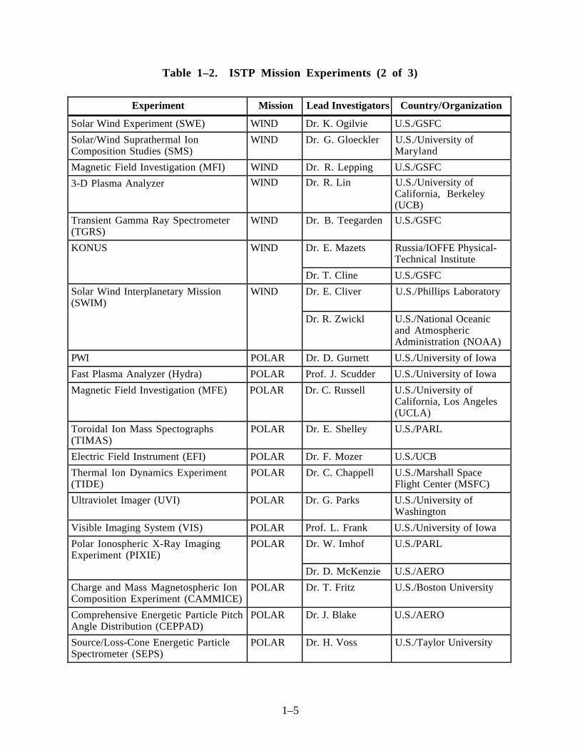
Table 1–2. ISTP Mission Experiments (2 of 3)
Experiment Mission Lead Investigators Country/Organization
Solar Wind Experiment (SWE) WIND Dr. K. Ogilvie U.S./GSFC
Solar/Wind Suprathermal IonComposition Studies (SMS)
WIND Dr. G. Gloeckler U.S./University ofMaryland
Magnetic Field Investigation (MFI) WIND Dr. R. Lepping U.S./GSFC
3-D Plasma Analyzer WIND Dr. R. Lin U.S./University ofCalifornia, Berkeley(UCB)
Transient Gamma Ray Spectrometer(TGRS)
WIND Dr. B. Teegarden U.S./GSFC
KONUS WIND Dr. E. Mazets Russia/IOFFE Physical-Technical Institute
Dr. T. Cline U.S./GSFC
Solar Wind Interplanetary Mission(SWIM)
WIND Dr. E. Cliver U.S./Phillips Laboratory
Dr. R. Zwickl U.S./National Oceanicand AtmosphericAdministration (NOAA)
PWI POLAR Dr. D. Gurnett U.S./University of Iowa
Fast Plasma Analyzer (Hydra) POLAR Prof. J. Scudder U.S./University of Iowa
Magnetic Field Investigation (MFE) POLAR Dr. C. Russell U.S./University ofCalifornia, Los Angeles(UCLA)
Toroidal Ion Mass Spectographs(TIMAS)
POLAR Dr. E. Shelley U.S./PARL
Electric Field Instrument (EFI) POLAR Dr. F. Mozer U.S./UCB
Thermal Ion Dynamics Experiment(TIDE)
POLAR Dr. C. Chappell U.S./Marshall SpaceFlight Center (MSFC)
Ultraviolet Imager (UVI) POLAR Dr. G. Parks U.S./University ofWashington
Visible Imaging System (VIS) POLAR Prof. L. Frank U.S./University of Iowa
Polar Ionospheric X-Ray ImagingExperiment (PIXIE)
POLAR Dr. W. Imhof U.S./PARL
Dr. D. McKenzie U.S./AERO
Charge and Mass Magnetospheric IonComposition Experiment (CAMMICE)
POLAR Dr. T. Fritz U.S./Boston University
Comprehensive Energetic Particle PitchAngle Distribution (CEPPAD)
POLAR Dr. J. Blake U.S./AERO
Source/Loss-Cone Energetic ParticleSpectrometer (SEPS)
POLAR Dr. H. Voss U.S./Taylor University

1–6
Table 1–2. ISTP Mission Experiments (3 of 3)
Experiment Mission Lead Investigators Country/Organization
Charge, Element, and Isotope AnalysisSystem (CELIAS)
SOHO Dr. D. Hovestadt
Dr. P. Boschler
Germany/Max PlanckInstitut
Switzerland/University ofBern
Comprehensive Suprathermal andEnergetic Particle Analyzer (COSTEP)
SOHO Dr. H. Kunow Germany/Institut fuerReine und AngewandteKernphysik
Energetic and Heliospheric RelativisticNuclei and Electron Experiment(ERNE)
SOHO Dr. J. Torsti Finland/University ofTurku
Table 1–3 lists the ISTP ground-based and theory investigations and their lead investigators.
Table 1–3. ISTP Ground-Based, Theory, and Other Investigations
Investigations Mission Lead Investigators Organization
Dual Auroral Radar Network (DARN) GBI Dr. R. Greenwald U.S./APL
Sondre Stromfjord Radar(SONDRESTROM)
GBI Dr. J. Kelly U.S./SRI International
CANOPUS Instrumentation GBI Dr. G. Rostoker Canada/University ofAlberta
SESAME Instrumentation GBI J. Dudeney U.K./British AntarcticSurvey (BAS)
Ionospheric-Magnetospheric Coupling(IMC)
THEORY Dr. M.Hudson U.S./Dartmouth College
Solar Wind Magnetospheric Coupling(SWMC)
THEORY Dr. D. Papadopoulos U.S./University ofMaryland
Total Energy Deposition (TED) THEORY Dr. M. Rees U.S./University of Alaska
Substorm Simulation (SS) THEORY Dr. M. Ashour-Abdalla
U.S./UCLA
MFE (X-40) IMP-8 Dr. R. Lepping U.S./GSFC
PWI (X-53) IMP-8 Dr. L. Lazarus U.S./MIT
Geostationary OperationalEnvironmental Satellite (GOES)
GOES Dr. R. Zwickl U.S./NOAA
Los Alamos National Laboratory(LANL)
LANL Dr. D. McComas U.S./LANL

1–7
1 .7 Overview of Interface
This DFCD is applicable to the following ISTP interfaces:
• CDHF to investigator RDAF• DDF to investigator RDAF• GDCF to CDHF• CDHF to DDF• GDCF to DDF
The CDHF to investigator RDAF interactive interface provides the following data:
• Remote users at the RDAFs with a complement of standard CDHF interactive services forreviewing the data catalog, transferring data files, qualifying key parameters, andcoordinating with others through electronic mail and a bulletin board
• Support in the form of documentation standards, utility software, KPGS developmentaccounts, and configuration management procedures for use by investigators in developingKPGS programs at the RDAF and delivering them to the CDHF for production use
• The capability to transfer KPGS to the CDHF via electronic means
The interactive service interface is implemented through National Aeronautics and SpaceAdministration (NASA) Science Internet (NSI) and CDHF-resident interactive menu software.NSI is a DEC network (DECnet) and Transmission Control Protocol/Internet Protocol (TCP/IP)-based wide area network linking the CDHF and all investigator RDAFs.
The following data items are transferred interactively from the CDHF to the ISTP investigators:
• Level-zero data to investigators of the experiment onboard the respective spacecraft• GEOTAIL Scientific Information Retrieval Integrated Utilization System (SIRIUS)-
formatted instrument data to ISAS and to GEOTAIL PIs and Co-Is• Spacecraft housekeeping data to investigators of experiments onboard the spacecraft• Key parameters for all experiments to all investigations• Predictive and definitive orbit data to all investigations• Predictive and definitive attitude data to all investigations• Spacecraft command history data to all investigators responsible for the instrument aboard
the respective spacecraft• Redistribution of lost or unreadable data to the appropriate investigators• Forced distribution to PIs before normal distribution time• Ad hoc distribution data not included in normal distribution• SOHO summary, command history, TCF, and SDR data to SOHO investigators
The DDF organizes the above types of data for distribution and writes them to physical media thatare mailed with an accompanying, computer-generated mailing letter detailing the contents toscientific investigators.
Initially, the DDF distributed data on only nine-track, 6250-bits per inch (bpi) magnetic tapes. Thetapes are American National Standards Institute (ANSI) standard-labeled tapes, which includeHEADER3. The DDF has begun distributing data on CD-ROM physical media. Magnetic tapecontinues to be available as an alternative data distribution medium.

1–8
The GTDM DCF to the CDHF interface provides the level-zero, SIRIUS, and spacecrafthousekeeping data. The CDHF-resident KPGS uses the level-zero and SIRIUS-formattedtelemetry data for generating key parameters.
The CDHF to the DDF interface provides the following:
• Level-zero data• SIRIUS-formatted data• Spacecraft housekeeping data• Key parameters for all experiments• Predictive and definitive orbit data• Predictive and definitive attitude data• Spacecraft command history data• Spacecraft quality and accounting (Q/A) data
The GTDM DCF to the DDF interface provides the following:
• POLAR wideband data• ISTP plotting subsystem (IPLOT) data

2–1
SECTION 2—ISTP DATA FORMAT OVERVIEW
______________________________________________________________________________
This section provides an overview description of the general format of the data files distributedfrom either the CDHF or the DDF to the scientific community of PIs, Co-Is, GBIs, and TIs. Tofacilitate understanding, this section includes background information and conceptual anddescriptive information on the standard formatted data units (SFDUs). It also introduces theconcept of a common format.
2 .1 Background and Scope
Note: The following two paragraphs were extracted from Reference 3.
A critical function of the ISTP Ground Data Processing System (GDPS) is the management of thedata products ingested, computed, and distributed by the system. At the outset, it was recognizedthat these products should be self-documenting and, where possible, use existing standards andschemes for data mamagement.
SFDUs have been chosen as the first level of management for the data products. A detached SFDUfile is used to identify and describe each ISTP data product. These SFDU files consist of AmericanStandard Code for Information Interchange (ASCII) metadata (data that describes data) about andpointers to the actual data products. The SFDU standard is defined and operated under the auspicesof the Consultative Committee for Space Data Systems (CCSDS). SFDUs operate by “labeling”data (or metadata) objects with 20-byte SFDU labels. The data product described by the SFDU isregistered with a control authority (CA). The CA used for the ISTP program is the National SpaceScience Data Center (NSSDC). Each registered data product has a unique registration number.SFDUs are constructed so that they are easy to view with standard computer tools (e.g., “TYPE”or “cat” commands.)
Note: SFDU headers for SOHO data files differ with respect to file-naming conventions and theREFERENCETYPE parameter depending on whether the data file is processed/used by the ISTPCDHF. This issue and which data files have which convention is discussed in Section D.1 ofAppendix D.
Reference 4, although not a final standard, documents the construction rules. The SFDU conceptsprovide the protocols needed to enable the transformation of the discipline-oriented data used todayinto a distributed worldwide scientific information repository for the future.
On a multimission, multi-instrument program such as the ISTP, there is a need to correlate ormerge science data from multiple instruments and multiple missions. Such correlation is verydifficult unless there is some commonality with respect to format and field definitions/descriptions.
The use of SFDU methodology ensures that the description of data format and data content is eithercontained with the data itself or can be readily obtained from a control authority. Thismethodology, however, does not resolve the problem of correlating or merging the science datafrom multiple instruments and missions.
To address this need, the ISTP/Global Geospace Science (GGS) data committee stronglyrecommended that distribution data files for key parameters, definitive parameters, and event datashare a common data format and a common data dictionary.
The common data dictionary would provide the means to ensure that identical data items aredescribed identically with respect to format, units of measurement, etc. This dictionary in

2–2
combination with a common data format that is consistent with the CDHF operational concepts anddesign is intended to facilitate the correlation and merging of the data from multiple ISTPexperiments.
By combining the structural, identification, labeling, and registration aspects of the SFDUmethodology with the concept of a computer software-interpretable common data format andcontent description language, a self-documenting, self-describing dataset can be produced withinthe constraints of the CDHF design. In addition, the common data format support software mustbe available off the shelf, must have maintenance support, and must be portable to those computerslikely to be used within the ISTP program.
It was decided at the April 1991 Science Working Group meeting that the NSSDC’s common dataformat (CDF) is to be used for key parameter, orbit, and attitude data. Through use of the NSSDC-supplied CDF software, the CDHF provides the key parameter, orbit, and attitude data files inmachine-independent, external representation. The investigators use NSSDC-provided CDFsupport utilities to convert the data from external representation to the native format of theirfacilities.
The CDHF provides an online catalog service for investigator’s usage in accessing ISTP data priorto its availability from the DDF. Files containing data descriptions about the organization of thescientific data may also be requested. The data descriptions are associated with data dictionariesthat contain semantic information about the variables in the datasets.
2 .2 ISTP Data Format Overview
This section provides essential properties of the ISTP data formats with respect to datamanagement, an initial recommendation for ISTP data formats, related elements of the SFDUstandard, aspects of the SFDU standard, and SFDU control authority and registration.
2 . 2 . 1 ISTP Data Format Requirements
ISTP data is transferred to various types of hardware, combined for science purposes, andarchived for retrieval and further analysis many years into the future. To support these purposes,the ISTP data format and associated software must provide and/or support the following basicservices:
• Data management, including precise and complete data annotation• Conceptual model and software interface for storage of and access to flat, multidimensional
data and associated metadata for application software development• Software interface to allow byte-level data access in support of user-written special
application software• Existing and available support software that searches and selects data or metadata across
time, instrument, and spacecraft boundaries and provides for efficient merging of suchdisparate data/metadata within the common format
• A generic, user-friendly applications interface to access and display such data and metadata• Frame portability among the various computers used by the ISTP scientific investigators
The ISTP data format must support data management by providing the ability to
• Identify distinct collections of data• Characterize them with certain attributes• Store and retrieve specific data collections on the basis of those attributes

2–3
• Transfer data collections and attributes to other, including heterogeneous, computersystems where they may be similarly managed
The ISTP data format must have the following properties in order to support ISTP datamanagement:
• The physical media, physical format, data format and related software must be supported(and must be likely to continue to be supported) for the life of the ISTP collaborativescience data analysis (estimated to continue past the year 2005)
• The format must support the management of the full range of ISTP data products (e.g., keyparameters, event, other) and of the related format and content metadata
• The format must be compact and efficient in its use of storage (e.g., minimal overhead fordata management services)
• The format must facilitate access to the data contents (“including the bits”) both within anindividual data collection or logical file and across related data collections
• The format and its support software must facilitate data transfer between several computerarchitectures and platforms likely to be used by the ISTP investigative community (e.g.,VAX/VMS, Sun, Apple Macintosh)
2 . 2 . 2 SFDU Standard for ISTP Data Formats
The SFDU approach was adopted as the highest level ISTP data format standard because theSFDU
• Is to be an international standard with growing acceptance throughout the space sciencescommunity
• Supports basic data management functions• Provides a framework for basic data interchange functions• Provides a standard to consistently encapsulate all levels of ISTP data• Provides procedures for the registration and dissemination of data definitions and
descriptions• Provides a standard way to link data to its description
2 . 2 . 3 SFDU Concepts
Fundamentally, the SFDU concept is a self-documenting labeling scheme that incorporates aregistration identifier in the label. The registration identifier corresponds to a collection of metadata(“data about data”) that defines the data format and its content.
Rather than being a standard format into which one puts data, the SFDU concept focuses onstandard data labeling to enhance the understanding of transmitted and stored data. The data may bein any user-defined arrangement that can be expressed precisely.
Information transfer ranges from single data elements to completely identified and definedproducts. A data element is an individually named data item that is used in a processing algorithmas a singular data parameter, variable, or attribute. Elements are collected and structured into dataobjects (aggregations of elements).
2–4
2.2.3.1 SFDU Structure and Construction Rules
The role of the SFDU structure and construction rules is to define standard methods for
• Labeling and delimiting data objects• Aggregating, collecting, and structuring sets of data objects to allow the use of standard
packaging and unpackaging techniques• Indicating the major type of data or metadata within a data object
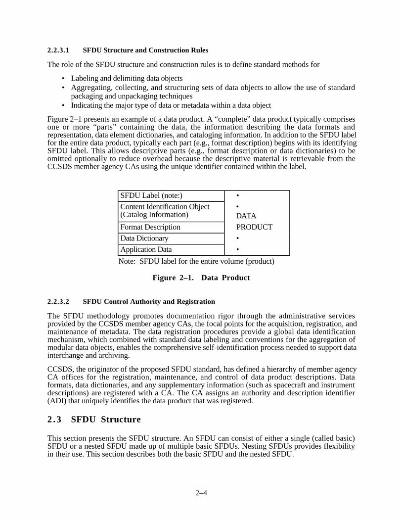
Figure 2–1 presents an example of a data product. A “complete” data product typically comprisesone or more “parts” containing the data, the information describing the data formats andrepresentation, data element dictionaries, and cataloging information. In addition to the SFDU labelfor the entire data product, typically each part (e.g., format description) begins with its identifyingSFDU label. This allows descriptive parts (e.g., format description or data dictionaries) to beomitted optionally to reduce overhead because the descriptive material is retrievable from theCCSDS member agency CAs using the unique identifier contained within the label.
SFDU Label (note:) •
Content Identification Object(Catalog Information)
•DATA
Format Description PRODUCT
Data Dictionary •
Application Data •
Note: SFDU label for the entire volume (product)
Figure 2–1. Data Product
2.2.3.2 SFDU Control Authority and Registration
The SFDU methodology promotes documentation rigor through the administrative servicesprovided by the CCSDS member agency CAs, the focal points for the acquisition, registration, andmaintenance of metadata. The data registration procedures provide a global data identificationmechanism, which combined with standard data labeling and conventions for the aggregation ofmodular data objects, enables the comprehensive self-identification process needed to support datainterchange and archiving.
CCSDS, the originator of the proposed SFDU standard, has defined a hierarchy of member agencyCA offices for the registration, maintenance, and control of data product descriptions. Dataformats, data dictionaries, and any supplementary information (such as spacecraft and instrumentdescriptions) are registered with a CA. The CA assigns an authority and description identifier(ADI) that uniquely identifies the data product that was registered.
2 .3 SFDU Structure
This section presents the SFDU structure. An SFDU can consist of either a single (called basic)SFDU or a nested SFDU made up of multiple basic SFDUs. Nesting SFDUs provides flexibilityin their use. This section describes both the basic SFDU and the nested SFDU.

2–5
2 . 3 . 1 SFDU Structure—Basic
The basic SFDU structure is called the Label-Value-Object (LVO). The LVO is the fundamentalstructural element used to build SFDUs. An LVO, as shown in Figure 2–2, contains two fields: a20-byte label field followed by a variable-length value field. Depending on the label-field values,the LVO may contain a marker to indicate the end of the SFDU.
LabelField specification
based on Version ID (fixed size)
Registration information
Delimitation information
Value
Variable field size (Delimited using a parameter in the
label field)
Application data or supplementary data or identification data or
data description data or any other form of data
Optional Marker
Existence based on label field values
Figure 2–2. Label-Value-Object (LVO) Structure
Figure 2–2 illustrates a schematic of an SFDU (LVO) and shows the kind of information foundwithin both the label field and the value field.
2 . 3 . 2 Label Subfields
The label field provides the CCSDS CA registration information and specifies how the value fieldis delimited. The label field contains the following subfields:
• Control authority identifier (CAID)• Version• Class• Spare/delimitation type• Spare bytes• Data description identifier (DDID)• Delimitation parameter
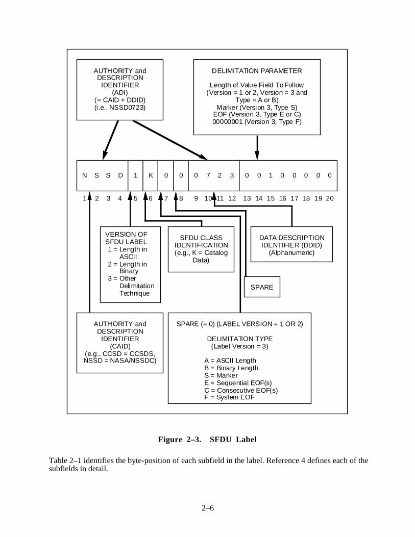
Figure 2–3 presents an example of an SFDU label. The figure shows the byte position andpossible contents of each label subfield. The figure also provides concise descriptions of thesubfield contents.
2–6
AUTHORITY and DESCRIPTION
IDENTIFIER (ADI)
(= CAID + DDID) (i.e., NSSD0723)
N S S D 1 K 0 0 0 7 2 3 0 0 1 0 0 0 0 0
DELIMITATION PARAMETER
Length of Value Field To Follow(Version = 1 or 2, Version = 3 and
Type = A or B)Marker (Version 3, Type S)
EOF (Version 3, Type E or C)00000001 (Version 3, Type F)
1 2 3 4 5 6 7 8 9 10 11 12 13 14 15 16 17 18 19 20
VERSION OF SFDU LABEL1 =Length in
ASCII2 =Length in
Binary3 =Other
Delimitation Technique
SPARE (= 0) (LABEL VERSION = 1 OR 2)
DELIMITATION TYPE(Label Version = 3)
A = ASCII LengthB = Binary LengthS = MarkerE = Sequential EOF(s)C = Consecutive EOF(s)F = System EOF
AUTHORITY and DESCRIPTION
IDENTIFIER (CAID)
(e.g., CCSD = CCSDS, NSSD = NASA/NSSDC)
SFDU CLASS IDENTIFICATION(e.g., K = Catalog
Data)
DATA DESCRIPTION IDENTIFIER (DDID)
(Alphanumeric)
SPARE
Figure 2–3. SFDU Label
Table 2–1 identifies the byte-position of each subfield in the label. Reference 4 defines each of thesubfields in detail.

2–7
Table 2–1. Label Subfields
Bytes Subfield
1–4 Control Authority Identifier (CAID)
5 Version
6 Class
7 Spare/Delimitation Type
8 Spare bytes reserved for future use (SP)
9–12 Data Description Identifier (DDID)
13–20 Delimitation Parameter
The values entered in the label subfields are represented using a restricted ASCII (RA) characterset. The valid characters are 0–9 and uppercase A–Z. Each valid character, with its decimal,binary, and hexadecimal equivalent, is listed in Reference 4. (Note that the delimitation parametersubfield may contain other than an ASCII value.)
The following sections briefly define the label subfields.
2.3.2.1 Control Authority Identifier and Data Description Identifier
Two of these subfields are the CAID and the DDID. The CAID, in bytes 1–4, identifies theCCSDS member agency CA office that maintains the format definition (has registrationresponsibility for the data description information). The DDID, in the last 4 bytes (bytes 9–12),combined with the CAID, uniquely identifies the data definition information that applies to theValue field data. Together, the CAID and DDID make up the ADI, a globally unique name for theValue field description.
2.3.2.2 Version
The 1-byte version subfield in byte 5 indicates the label version with respect to how the end of thevalue field is determined. There are two basic ways for this as follows:
• The value-field length is provided in the label.• The end of the value field is denoted by a delimiter.
The version subfield can have three possible values as follows:
Version Meaning
1 The delimitation parameter contains the value field length in ASCII(1 to 8 bytes, as applicable)
2 The delimitation parameter contains the value field length in binary(64-bit unsigned integer with leading zero bits as needed)
3 A delimitation technique other than specifying the length is beingused (see delimitation type)

2–8
The delimitation parameter contains a length value when version equals either “1” or “2.”Table 2–2 should serve to clarify the length representation with respect to the version value.
Table 2–2. Length Representation With Respect to Version Value
Decimal Hexadecimal Version = 1 Version = 2
Value Value Decimal ASCII Binary
25 19 3235 0000 0000 0001 1001
10 A 3130 0000 0000 0000 1010
100 64 313030 0000 0000 0110 0100
1000 3E8 31303030 0000 0011 1110 1000
2.3.2.3 Class
The class subfield in byte 6 is used to classify the content of the value field. There are threecategories of classes: structure, service, and data. The class IDs by category are listed, and theclasses are described in detail in Reference 4.
2.3.2.4 Delimitation Type
This subfield, in byte 7, is used to specify the type of value field delimitation when label versionequals “3.” Otherwise (if version equals either “1” or “2”), this subfield is a null-filled spare. Thedelimitation type indicators and associated descriptions are as follows:
Delimitation Type Description
A ASCII LengthB Binary LengthS MarkerE Sequential end-of-file (EOF) marker(s)C Consecutive EOF marker(s)F System EOF
Note that ASCII length or binary length can be specified in two different ways. ASCII length canbe denoted by either version = “1” or version = “3” and type = “A”. Binary length can be denotedby either version = “2” or version = “3” and type = “B”.
2.3.2.5 Spare
Byte 8 is a spare byte reserved for future use.
2–9
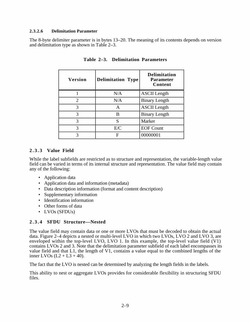
2.3.2.6 Delimitation Parameter
The 8-byte delimiter parameter is in bytes 13–20. The meaning of its contents depends on versionand delimitation type as shown in Table 2–3.
Table 2–3. Delimitation Parameters
Version Delimitation TypeDelimitation
ParameterContent
1 N/A ASCII Length
2 N/A Binary Length
3 A ASCII Length
3 B Binary Length
3 S Marker
3 E/C EOF Count
3 F 00000001
2 . 3 . 3 Value Field
While the label subfields are restricted as to structure and representation, the variable-length valuefield can be varied in terms of its internal structure and representation. The value field may containany of the following:
• Application data• Application data and information (metadata)• Data description information (format and content description)• Supplementary information• Identification information• Other forms of data• LVOs (SFDUs)
2 . 3 . 4 SFDU Structure—Nested
The value field may contain data or one or more LVOs that must be decoded to obtain the actualdata. Figure 2–4 depicts a nested or multi-level LVO in which two LVOs, LVO 2 and LVO 3, areenveloped within the top-level LVO, LVO 1. In this example, the top-level value field (V1)contains LVOs 2 and 3. Note that the delimitation parameter subfield of each label encompasses itsvalue field and that L1, the length of V1, contains a value equal to the combined lengths of theinner LVOs (L2 + L3 + 40).
The fact that the LVO is nested can be determined by analyzing the length fields in the labels.
This ability to nest or aggregate LVOs provides for considerable flexibility in structuring SFDUfiles.

2–10
1 K 0 0 0723CSSDLabel 120 bytes
Length 1 (L1)00010000
VALUE
1(V1)
L2
V2
L3
V3
L2
Label 320 bytes
L3
Label 220 bytes
L110,000 bytes
Note: V1 is L1 (10,000) bytes long. Likewise, V2 is L2 bytes long; V3 is L3 bytes long. Thethree labels (Label 1, Label 2, and Label 3) each contain 20 bytes, as do all SFDUlabels. L2 + L3 + 40 (the combined lengths of Labels 2 and 3) = 10,000. Therefore,V2 + V3 contain 9,960 line (i.e., 10,000-40) bytes.
Figure 2–4. Nested LV Object (SFDU)
2 .4 SFDU in the ISTP CDHF
The CDHF requires that all files managed by the CDHF system have ISTP SFDUs associated withthem. The CDHF Data Management System uses the ISTP SFDUs to identify the data files, anddescribe their contents. Although the CDHF design can support either attached or detached ISTPSFDUs, all files currently managed by the CDHF have detached ISTP SFDUs. All detached ISTPSFDUs within the CDHF have the file extension “.SFDU”. The ISTP SFDU files are formatted tobe easily viewable at a terminal. They may be typed out using the VMS TYPE command or viewedby using a text editor or by using the DISPLAY_SFDU command. This section describes theformat and content of the ISTP SFDUs used by the CDHF for ISTP data files.

2–11
2 . 4 . 1 CDHF SFDU Structure
The detached ISTP SFDUs used by the CDHF consist of 512-byte, fixed-length records. Theunused portion of any record is blank filled. Each ISTP SFDU consists of the appropriate SFDUlabels, a contents identifier object (CIO), and a reference object.
The CIO is in keyword = value format and contains identifying or descriptive information such asproject name, data type (e.g., level-zero), start and stop times, etc.
2 . 4 . 2 Parameters in the CIO
Parameters within the CIO are packed into the 512-byte records, in the form of parameter/valuestrings, separated by semicolons (;). In addition, to allow the CIO to be easily listed to a terminalscreen, a carriage return and line feed (CR LF) is placed after each semicolon. This causes eachparameter to appear on a separate line when listed to the terminal with standard listing tools such asthe VAX/VMS TYPE command or the UNIX “cat” command. Parameter/value strings are notwrapped between records. If a parameter/value string will not completely fit in an existing record,the record is blank filled and the string is written to the beginning of the next record. This meansthat a single parameter/value string may not exceed 510 bytes in length (510 bytes plus the 2-byteCR LF equals the 512-byte record length).
A general set of parameter names for the CIO has been derived from the Directory InterchangeFormat Manual, Version 3.0, December 1990 NASA GSFC, NSSDC. These have beensupplemented with the additional parameters needed to describe the ISTP data files fully. Someparameters have multiple values (i.e., both a short and a long name). In these cases, the values areseparated by a “>.” The ADI number assigned by the NSSDC to the CIO used for ISTP data isNSSD0060. This information appears in the 20-byte SFDU label.
The valid parameters for an ISTP SFDU CIO are listed below. Required parameters are soindicated.
Project (required)Discipline (required)Source_name (required)Data_type (required)Descriptor (required)Start_date/Stop_date (required)Data_Version (required)ICSS_release (optional)Generation_date (optional)Generation_program (optional)File_id (optional)Input_file (optional)Comment (optional)Begin_group/End_group (optional)
A detailed description of each parameter is provided in the following subsections.
2–12
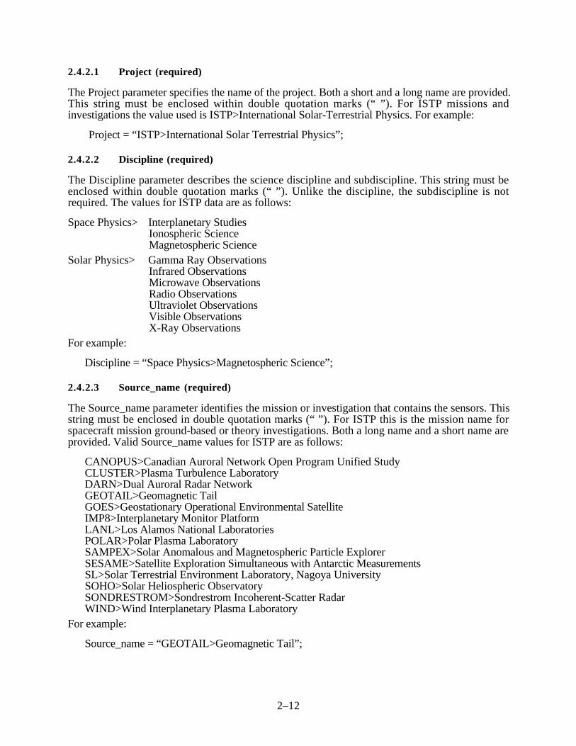
2.4.2.1 Project (required)
The Project parameter specifies the name of the project. Both a short and a long name are provided.This string must be enclosed within double quotation marks (“ ”). For ISTP missions andinvestigations the value used is ISTP>International Solar-Terrestrial Physics. For example:
Project = “ISTP>International Solar Terrestrial Physics”;
2.4.2.2 Discipline (required)
The Discipline parameter describes the science discipline and subdiscipline. This string must beenclosed within double quotation marks (“ ”). Unlike the discipline, the subdiscipline is notrequired. The values for ISTP data are as follows:
Space Physics> Interplanetary StudiesIonospheric ScienceMagnetospheric Science
Solar Physics> Gamma Ray ObservationsInfrared ObservationsMicrowave ObservationsRadio ObservationsUltraviolet ObservationsVisible ObservationsX-Ray Observations
For example:
Discipline = “Space Physics>Magnetospheric Science”;
2.4.2.3 Source_name (required)
The Source_name parameter identifies the mission or investigation that contains the sensors. Thisstring must be enclosed in double quotation marks (“ ”). For ISTP this is the mission name forspacecraft mission ground-based or theory investigations. Both a long name and a short name areprovided. Valid Source_name values for ISTP are as follows:
CANOPUS>Canadian Auroral Network Open Program Unified StudyCLUSTER>Plasma Turbulence LaboratoryDARN>Dual Auroral Radar NetworkGEOTAIL>Geomagnetic TailGOES>Geostationary Operational Environmental SatelliteIMP8>Interplanetary Monitor PlatformLANL>Los Alamos National LaboratoriesPOLAR>Polar Plasma LaboratorySAMPEX>Solar Anomalous and Magnetospheric Particle ExplorerSESAME>Satellite Exploration Simultaneous with Antarctic MeasurementsSL>Solar Terrestrial Environment Laboratory, Nagoya UniversitySOHO>Solar Heliospheric ObservatorySONDRESTROM>Sondrestrom Incoherent-Scatter RadarWIND>Wind Interplanetary Plasma Laboratory
For example:
Source_name = “GEOTAIL>Geomagnetic Tail”;

2–13
2.4.2.4 Data_type (required)
The Data_type parameter identifies the data type of the data file associated with the CIO. Both along name and a short name are given. This string must be enclosed within quotation marks (“ ”).Valid names for ISTP are as follows:
AN>Ancillary DataAR>As-Run PlanAT>AttitudeCD>Calibration DataCH>Command HistoryKx>Key Parameter (x is a number from 0 to 9)LZ>Level-ZeroPA>Platform AttitudePP>Prime ParametersOR>OrbitQL>Level-Zero QuicklookSD>SIRIUSSP>Summary ParametersSU>SummaryWA>Working AttitudeWO>Working Orbit
For key parameter data types, 1 to 10 separate key parameter files can be derived from the sameinput telemetry file. Separate files are used in cases where sets of key parameters are generated thatcannot be efficiently combined in a single file. An example of this is sets of key parametersgenerated at different time intervals. For example:
Data_type = “K0>Key Parameter”;
2.4.2.5 Descriptor (required)
The descriptor identifies the name of the instrument or sensor that collected the data or furtheridentifies the type of data. Both a long name and a short name are given. Valid values for the shortname and the associated long name are listed in Section 2.6 and can be found in the CDHF catalog.For example:
Descriptor = “VIS>Optical Auroral Imager”;Descriptor = “PRE>Predicted Data”;
2.4.2.6 Start_date/Stop_date (required)
These parameters contain the first and last dates and times of the data associated with the SFDU.Dates and times are specified in a form compatible with International Organization forStandardization (ISO) 8601. All dates and times for ISTP are given as a date with universal timecoordinated (UTC). This is indicated by the ‘Z’ following the time field. Times are given to secondand decimal fractions of seconds. If the SFDU references multiple data files, the Start and Stoptimes in the CIO represent the earliest start and latest stop times for the data files in the group. Forexample:
Start_date = 1993–06–12T13:05:22.0Z;Stop_date = 1993–06–12T23:59:45.5Z;

2–14
2.4.2.7 Data_version (required)
The Data_version parameter indicates the version of the data file or data file group associated withthis SFDU. Data_version starts at ‘1’ and is incremented for each subsequent generation of thedata. For example:
Data_version = 2;
2.4.2.8 Generation_date (optional)
The Generation_date parameter contains the date and time when the data was generated. In the caseof data received by the CDHF, this is the date and time the data was created by the originator. Fordata files generated by the CDHF (e.g., key parameter files), this is the date and time of creation onthe CDHF. Dates and times are specified in a form compatible with ISO 8601. All dates and timesfor ISTP data are given as a date with UTC time. This is indicated by the ‘Z’ following the timefield. Times are given in seconds. For example:
Generation_date = 1993–06–12T14:25:27.0Z;
2.4.2.9 Generation_program (optional)
The Generation_program parameter identifies the program that generated the data file. Both thename and version of the program should be identified. For example:
Generation_program = WI_WAV_KPG_V1.2;
2.4.2.10 File_id (optional)
The File_id parameter identifies the SFDU and the data file or data file group associated with theSFDU. Both the SFDU and the data files in the group should have this parameter incorporatedinternally (the SFDU, as part of the CIO and the data files as part of their embedded metadata-data). The CDHF convention for naming data files and their associated detached SFDUs is to givedata files and SFDU files the same filename with different extensions. File_id serves as amechanism independent of the physical filename to associate an SFDU with a specified data file.For example:
File_id = PO_K0_UVI_19960914_V01;
The above example would identify the following physical files:
PO_K0_UVI_19960914_V01.SFDUPO_K0_UVI_19960914_V01.DAT
2.4.2.11 Input_file (optional)
The Input_file parameter identifies the input files (if any) that were used to create the data fileassociated with this SFDU. This parameter may appear as many times as there are input files. Forexample:
Input_file = PO_LZ_UVI_19960914_V01;Input_file = PO_OR_PRE_19960914_V01;Input_file = PO_AT_PRE_19960914_V01;

2–15
2.4.2.12 Comment (optional)
The Comment parameter allows the insertion of comments in the SFDU and may appear as manytimes as desired. Each comment must be enclosed within quotation marks (“ ”). For example:
Comment = “Instrument turned off between 0800 and 1430”;
2.4.2.13 Begin_group/End_group (optional)
These parameters are used to delimit parameter groups within a single CIO, for example whenmultiple CIOs are merged to form a single SFDU. The value of the parameter identifies thegrouping. The same value must be assigned to the Begin_group/End_group pair that delimits agrouping.
2.4.2.13.1 CIO Group
The CIO group is used to concatenate multiple CIOs into a single SFDU when multiple data filesare concatenated to form a single data file. This preserves the information contained in the SFDUfor each of the concatenated data files. For example:
Begin_group = CIO;Project = “ISTP>International Solar Terrestrial Physics”;Discipline = “Space Physics>Ionospheric Studies”;Source_name = “POLAR>Polar Plasma Laboratory”;Data_type = “K0>Key parameter”;Descriptor = “VIS>Optical Auroral Imager”;Start_date = 1996–09–14T13:05:22.3Z;Stop_date = 1996–09–14T23:59:45.7Z;Data_version = 1Generation_date = 1996-06-16T14:25:27.0Z;File_id = PO_KP_UVI_19960914_V01;Input_file = PO_LZ_UVI_19960914_V01;Input_file = PO_OR_PRE_19960914_V01;Input_file = PO_AT_PRE_19960914_V01;
End_group = CIO;Begin_group = CIO;
Project = “ISTP>International Solar Terrestrial Physics”;Discipline = “Space Physics>Ionospheric Studies”;Source_name = “POLAR>Polar Plasma Laboratory”;Data_type = “K0>Key parameter”;Descriptor = “VIS>Optical Auroral Imager”;Start_date = 1996–09–15T00:04:02.1Z;Stop_date = 1996–09–15T23:59:15.3Z;Data_version = 1;Generation_date = 1996–09–17T12:35:21.0Z;File_id = PO_KP_UVI_19960915_V01;Input_file = PO_LZ_UVI_19960915_V01;Input_file = PO_OR_PRE_19960915_V01;Input_file = PO_AT_PRE_19960915_V01;
End_group = CIO;

2–16
2.4.2.13.2 REFDES Group
The REFDES group is a reference file description group. It is used to provide additionalinformation on each of the files listed in the REFERENCE parameter of the reference object (seeSection 3.6.3.2). The parameters in the CIO apply to the set of files listed in the Reference Object.The REFDES group is useful in instances where start and stop dates for individual files aredifferent (e.g., for SIRIUS data file groups).
The REFDES group consists of three parameters repeated as many times as there are files listed inthe REFERENCE parameter. These parameters are as follows:
Ref_file This parameter identifies the file to which the following parametersapply. Its value exactly matches one of the filenames in theREFERENCE parameter of the Reference object.
Start_date/Stop_date These parameters have the same meaning as they do in the CIO. Herethey refer to the start and stop dates of the file specified by theREF_file parameter.
Example:
x1 = REFDES;Ref_file = GE_SD_NUL_19920922_V01.S01;Start_date = 1992 – 09 – 22T00:02:42.25Z;Stop_date = 1992 – 09 – 22T06:12:37.55Z;Ref_file = GE_SD_NUL_19920922_V01.S02;Start_date = 1992 – 09 – 22T06:13:22.75Z;Stop_date = 1992 – 09 – 22T12:30:36.51Z;Ref_file = GE_SD_NUL_19920922_V01.S03;Start_date = 1992 – 09 – 22T12:30:44.25Z;Stop_date = 1992 – 09 – 22T18:32:17.12Z;Ref_file = GE_SD_NUL_19920922_V01.S04;Start_date = 1992 – 09 – 22T18:33:12.71Z;Stop_date = 1992 – 09 – 22T23:59:58.57Z;End_group = REFDES;
This example shows the REFDES group for a SIRIUS data group consisting of four files.
2.4.2.14 ICSS_release (optional)
The ICSS_release indicates the release of the ICSS that generated the SFDU. SFDUs createdexternal to the CDHF will not contain this parameter.
Example: ICSS_release = “Release 5.1”;
2 . 4 . 3 Parameters in the Reference Object
The reference object of the SFDU is used to point to the data file or files associated with theSFDU. Parameters in the reference object are inserted in the 512-byte records in the same manneras those in the CIO with the exception that the value of the REFERENCE parameter may spanmore than one 512-byte record. Each parameter is separated from the next by a semicolon and aCR LF combination.

2–17
2.4.3.1 REFERENCETYPE
This parameter identifies the type of reference object. For ISTP the reference object type is definedas ($CCSDS3). The REFERENCETYPE parameter may contain subparameters that are project-defined. Currently, no subparameters are defined for ISTP. For example:
REFERENCETYPE = ($CCSDS3);
2.4.3.2 Label
The label parameter indicates what the label for the data object would have been had the data beenattached to this SFDU. The label identifies where the data object ends and defines where thedefinition for the data object is registered. The ADI number for the data product referred to by theSFDU is contained in the label in bytes 1–4 and 9–12. In the following example, the ADI is inboldface. Appendix D lists the ADI numbers assigned to the ISTP data products. For example:
LABEL = NSSD3IE0006500000001;
2.4.3.3 Reference
The REFERENCE parameter identifies the files associated with the SFDU. For the CCSDS3REFERENCETYPE, the REFERENCE parameter gives the name of the file in a long and a shortformat. The long form of the name is the name as the file appears on the CDHF. The short form ofthe name is an 8.3-format name (eight-character filename and three-character extension). The 8.3form of the filename is the format that is used on the ISO 9660 CD-ROMs. For CCSDS2 SFDUs,the REFERENCE parameter gives the long name of the file only. The CDHF will convert anyCCSDS2 SFDUs to CCSDS3 when they are received. All files generated by the CDHF will haveCCSDS3 format SFDUs. VMS file version numbers are not included as part of the filename formin the REFERENCE parameter for either CCSDS2 or CCSDS3.
CCSDS2 example:REFERENCE = (WI_KO_WAV_19940715_V01.CDF);
CCSDS3 example:REFERENCE = (“$1 = 94071501.CDF, $2 = WI_K0_WAV_19940715_ V01.CDF”);
2 .5 SFDU Example for ISTP
Figure 2–5 is an example that illustrates the SFDU concepts as applied to ISTP data files managedby the CDHF. The example is for a Satellite Experiments Simultaneous With AntarcticMeasurements (SESAME) key parameter file.
A 20-byte SFDU label is shown at the beginning (first 20 bytes of first line) of the data product.This is the label for the entire SFDU file. The first 12 bytes (CSSD1Z000001) identify the file asan SFDU. Since version (byte 5) equals “1”, the next 8 bytes (00001004) contain the length inbytes of the entire SFDU file less this label. Thus, the SFDU has a length of 1004 bytes plus20 bytes or 1024 bytes.
The next 20 bytes (last 20 bytes of first line) contain the SFDU label associated with the CIO(NSSD1K00006000000740). The boldface NSSD in bytes 1–4 and 0060 in bytes 9–12 indicatethat the description of the contents and format of the content identification is registered with theNSSDC CA with an ADI of NSSD0060. The 8-byte length in the delimitation parameter subfieldof this label indicates that the CIO (not counting this 20-byte label) contains 740 bytes.

2–18
CCSD1Z00000100001004NSSD1K00006000000740
Project = “ISTP > International Solar-Terrestrial Physics”;
Discipline = “Space Physics > Magnetospheric Science”;
Source_name = “SESAME > Satellite Exploration Simultaneous With Antarctic Measurements”;
Data_type = “K0 > Key parameters”;
Descriptor = “VLF > VLF/ELF Logger Experiment (VELOX)”;
Start_date = 1992-07-06T00:00:35.0Z;
Stop_date = 1992-07-06T23:59:35.0Z;
Generation_date = 1992-07-25T12:47:31.3Z;
Data_version = 1;
Generation program = VLF_CDF.FOR;
File_id = SE_K0_VLF_19920706_V01;
Input_file = SE_K0_VLF_19920706_V01.ASC;
Comment = “Mean omnidirectional logarithmic intensities (dB) at”;
Comment = “1 kHz and 3 kHz with 1 kHz bandwidth”;
Comment = “Determined each minute. 0 dB corresponds to 10-33(T)2 (Hz)-1”;
CCSD1R00000300000224
REFERENCETYPE = ($CCSDS3);
LABEL = NSSD31E0010100000001;
REFERENCE = (“$1 = 92070601.CDF, $2 = SE_K0_VLF_19920706_V01.CDF”);
Note: This sample is for a CCSDS3 SESAME VLF key parameter file.
Figure 2–5. ISTP SFDU Example
The CIO in this example provides values for the following identifying parameters: project,discipline, source_name, data_type, descriptor, start_ and stop_dates, generation_date,data_version, generation_date, generation_program, file_id, input file, and three freeformcomment lines.
CCSD1R00000300000224, the SFDU label for the Reference Object, follows the CIO. The “R”indicates this object contains reference information. The “REFERENCETYPE” specifiesthe”LABEL” value indicates the definition of the associated data object is registered at the NSSDCwith an ADI of NSSD0101. The version = “3”, delimitation type = “E” delimitation parameter =“00000001” combination indicates the data object is one file (i.e., is delimited by one EOF mark).
2 .6 File-Naming Conventions
The ISTP CDHF uses “long” filenames to convey maximum information in the names. In general,filenames are composed of a concatenation of relevant information that provides for uniqueidentification of a dataset.

2–19
An ISTP CDHF filename consists of a logical file identifier and an extension. A period (.)separates the extension from the logical file identifier.
Logical file identifiers are a concatenation of five fields that identify the mission, data type, datadescriptor, date, and version of the data file. Each of these fields is separated by an underscorecharacter. Blank characters are not allowed in the file identifier. The fields should be treated asvariable-length fields. However, note the following: at this time the allowed values for eachindividual field with the exception of descriptor are all the same length (e.g., all mission identifierscontain two characters). All current descriptor fields contain three or four characters. The logicalfile identifier is constructed as follows:
mission_datatype_descriptor_date_version
The fields are defined as follows:
• Mission—Identifies the mission or investigation (e.g., GE for GEOTAIL)• Datatype—Identifies the type of data (e.g., LZ for level zero)• Descriptor—Describes or further qualifies the source of the data (e.g., PRE for predictive
data)• Date—Identifies the starting date of the data in the file, in the form YYYYMMDD• Version—Identifies the version of the data (01–99)
In addition to the logical file identifier, each data file has a file extension associated with it whichserves to identify the individual components of a multifile group. A fully specified data file consistsof the disk/directory VMS logical, the logical file identifier and the extension. All files in multifilegroups have the same logical file identifier but different file extensions.
A few specific examples follow:
GE_LZ_QAF_19920912_V01.SFDUGE = GEOTAIL missionQAF = Quality fileLZ = Level-zero data type19920912 = Data starting on September 12, 1992V01 = Version 1 of this fileSFDU = Indicates SFDU fileWI_CH_NUL_19930115_V01.DATWI = WIND missionCH = Command history dataNUL = Field not applicable19930115 = Data starting on January 15, 1993V01 = Version 1 of this fileDAT = Indicates generic data type fileGE_SD_NUL_19920912_V01.S01GE = GEOTAIL missionSD = SIRIUS data typeNUL = Descriptor for SIRIUS data is not applicable19920912 = Data starting on September 12, 1992V01 = Version 1 of this fileS01 = Indicates segment 1 of the SIRIUS data file group

2–20
GE_SD_NUL_19920912_V01.SFDUGE_SD_NUL_19920912_V01.S01GE_SD_NUL_19920912_V01.S02GE_SD_NUL_19920912_V01.S03GE_SD_NUL_19920912_V01.S04
The above group of files constitutes a multifile group of SIRIUS data files. Note that the logicalfile identifier is the same for each file in the group. The group consists of a single SFDU file andfour data files.
The valid values for each of the fields of the logical file identifier are described in the following list.The Data File Types and Retention Periods form in the Database Interface System always containsthe current mission, data type, and descriptor combinations for all active missions. Descriptorvalues for some missions [e.g., Solar Heliospheric Laboratory (SOHO)] are TBD.
Mission:
C1 = CLUSTER Spacecraft # 1C2 = CLUSTER Spacecraft # 2C3 = CLUSTER Spacecraft # 3C4 = CLUSTER Spacecraft # 4CL = CLUSTER MissionCM = ClementineCN = CANOPUSDN = DARNG6 = GOES 6G7 = GOES 7G8 = GOES 8G9 = GOES 9GE = GEOTAILI8 = Interplanetary Monitoring Platform (IMP-8)IN = Interball-TailL0 = LANL 1990_095L1 = LANL 1991_080L9 = LANL 1989_046PO = POLARSE = SESAMESL = Solar-Terrestrial Environmental Laboratory, Nagoya UniversitySN = SondrestromfjordSO = SOHOSX = Solar Anomalous and Magnetospheric Particle Explorer (SAMPEX)UL = UlyssesWI = WINDXX = All missions
Data Type:
AN = Ancillary dataAR = As-run planAT = AttitudeCD = Calibration dataCH = Command historyK0-K9 = Key parameters (10 files maximum per instrument)

2–21
LZ = Level zeroOR = OrbitPA = Platform attitudePP = Prime parametersQL = Quick lookSD = SIRIUS dataSP = Summary parametersSU = Summary dataHANWA = Working attitudeWO = Working orbit
Descriptor:
DEF = Definitive dataLNG = Long-term predictedNUL = Indicates field does not applyPRE = Predicted data
CANOPUS:
ASI = All Sky ImagerBARS = Bistatic Auroral Radar SystemMARI = Magnetometer and Riometer Array (MARIA)MPA = Meridan Photometer Array
CLUSTER:
ASP = Active Spacecraft Potential Control (ASPOC)AUX = AuxiliaryCIS = CLUSTER Ion Spectrometry ExperimentDWP = Digital Wave-Processing ExperimentEDI = Electron Drift InstrumentEFW = Spherical Probe Electric Field and Wave ExperimentFGM = Magnetic Field InvestigationPEA = Plasma Electron and Current Experiment (PEACE)RAP = Imaging Energetic Particle Spectrometer (RAPID)STA = Spatio-Temporal Analysis of Field Fluctuations Experiment (STAFF)WHI = Sounder and High-Frequency Wave Analyzer Experiment (WHISPER)
DARN:
AARC = Halley/Syowa/SanaeALPA = Alaska/Prince AlbertBARS = Bars Very-High-Frequency (VHF) RadarCTLS = Iceland/Finland (Cutlass)GBAY = Goose Bay High-Frequency (HF) RadarGBST = Goose Bay/StokkseyriHANK = Hankasalmi (Cutlass/Finland) RadarICEW = Iceland West RadarKAPU = KapuskasingPYK = Pykkvybaer (Cutlass/Iceland) RadarSABR = SABRE VHF RadarSAKA = Saskatoon/KapuskasingSASK = Saskatoon

2–22
SHAR = SHARE (Sange Station) RadarSYOW = Syowa Stations Radar
GEOTAIL:
CPI = Comprehensive Plasma CompositionEFD = Electric FieldEPI = Energetic Particles and Ion Composition (EPIC)HEP = High-Energy Particles (LZ only)LEP = Low-Energy ParticlesMGF = Magnetic FieldPWI = Plasma Wave InstrumentQAF = Quality FileSCR = Spacecraft HousekeepingSPHA = Spin Phase
GOES:
EP8 = Low-Energy Particle and Electrons (Different Energies from EPS)EPS = Low-Energy Particle and Electrons (E1 and P1 Channel)MAG = Magnetometer
IMP-8:
MAG = Magnetic Field InvestigationMCE = Multi-Coordinate EphemerisPLA = Plasma Investigation
Interball-Tail:
DEF = Definitive DataELE = Thermal Electron ExperimentEPI = Energetic Particle ExperimentICD = Ion CompositionMFI = Magnetic Fields InstrumentPCI = PC Geomagnetic Index
LANL:
MPA = Magnetospheric Plasma AnalyzerSPA = Synchronous Orbit Particle Analyzer
POLAR:
CAM = Charge and Mass Magnetospheric Ion Composition Experiment (CAMMICE)CEP = Comprehensive Energetic Particle Pitch Angle Distribution (CEPPAD)EFI = Electric Fields InvestigationHYD = Fast Plasma Analyzer (HYDRA)MFE = Magnetic Fields ExperimentPDC = VIS Pixel Distortion Correction FilePIX = Polar Ionospheric X-Ray Imaging Experiment (PIXIE)PWI = Plasma Wave InstrumentQAF = Quality FileSCR = Spacecraft HousekeepingSEPS = Source/Loss-Cone Energetic Particle Spectrometer

2–23
SPHA = Spin PhaseTID = Thermal Ion Dynamics Experiment (TIDE)TIM = Torodial Imaging Mass Angle Spectrograph (TIMAS)UVI = Ultraviolet ImagerVIS = Visible Imaging SystemVLT = VIS Lookup Table
SAMPEX:
30F = 30 Second FluxesPOF = Polar Cap Fluxes
SESAME:
AIS = Advanced Ionospheric SounderFPI = Fabry-Perot InterferometerMAG = Fluxgate MagnetometerRIO = RiometerVLF = VLF/ELF Logger Experiment (VELOX)
SL:
210 = 210 Magnetic Network
SOHO:
CDS = Coronal Diagnostic SpectrometerCEL = Charge, Element, and Isotope Analysis System (CELIAS)CEP = COSTEP-ERNE Particle Analysis Collaboration (CEPAC)CST = Comprehensive Suprathermal and Energetic Particle analyzer (COSTEP)EIT = Extreme-Ultraviolet Imaging TelescopeERN = Energetic and Relativistic Nuclei and Electron experiment (ERNE)FTR = Full-time resolution attitude dataG001 = SVM HK1 packetsG002 = SVM HK2 packetsG003 = SVM HK3 packetsG004 = SVM HK4 packetsG005 = AOCS HK1 packetsG006 = AOCS HK2 packetsG007 = ATTITUDE 1 packetsG008 = ATTITUDE 2 packetsG009 = S/W packetsG010 = OBT packetsG011 = Experiment HK packetsG012 = CDS HK packetsG013 = CELIAS HK packetsG014 = CEPAC HK packetsG015 = EIT/LASCO HK1 packetsG016 = EIT/LASCO HK2 packetsG017 = EIT/LASCO HK3 packetsG018 = GOLF HK packetsG020 = Reserved EGSE packetsG022 = SUMER HK packetsG023 = SWA HK packets

2–24
G024 = UVC HK packetsG025 = VIRGO HK packetsG026 = CDS science LR packetsG027 = CDS science MR packetsG028 = CDS science HR packetsG029 = CEL science packetsG030 = CEP science packetsG031 = EIT/LASCO science LR packetsG032 = EIT/LASCO science HR packetsG033 = GOL science packetsG034 = MDI science packetsG035 = SUMER science LR packetsG036 = SUMER science HR packetsG037 = SWA science packetsG038 = UVC science packetsG039 = VIRGO science packetsG041 = MDI HK packetsGOL = Global Oscillations at Low Frequencies (GOLF)LAS = Large-Angle Spectrometric Coronograph (LASCO)MDI = Michelson Doppler ImagerSDR = SOHO Daily ReportSUM = Solar Ultraviolet Measurements of Emitted Radiation (SUMER)SWA = Solar Wind AnisotropiesTCF = Time Correlation FileUVC = Ultraviolet Coronal SpectrometerVIR = Variability of Solar Irradiance Gravity Oscillations (VIRGO)
Sondrestromfjord:
GISR = Greenland Incoherent Scatter Radar
WIND:
3DP = 3-D Plasma Analyzer (3DPA)EPA = Energetic Particle Acceleration Composition Transport (EPACT)KON = KonusMFI = Magnetic Fields InvestigationQAF = Quality FileSCR = Spacecraft HousekeepingSMS = Solar Wind Suprathermal Ion Composition Studies (SWICS/MASS/STICS)
(SMS)SPHA = Spin PhaseSWE = Solar Wind ExperimentTGR = Transient Gamma-Ray Spectrometer (TGRS)WAV = Radio and Plasma Wave Instrument (WAVES)WIFP = WIND Fields and Particle Parameters
Date:
YYYYMMDD, where:YYYY = 4-digit yearMM = month (01–12)DD = day of month (01–31)

2–25
Version:
Vnn = version of file (01–99)
The valid file extension values are as follows:
SFDU = an SFDU fileDAT = generic data fileSxx = Data file segment, where xx = 01–99CDF = CDF file
2 .7 Common Data Format
Note: Section 2.7 is essentially a reprint of the NSSDC’s CDF primer. Those familiar with theNSSDC’s CDF may omit reading this section. The CDF provides a standard format fordescribing, storing, and randomly accessing data. The CDF contains two major components: theactual data and the attributes which describe the data. The CDF also provides a standard softwarepackage called a CDF library that allows the user to create and access the data and the descriptiveattributes. CDF organizes data, which may be of assorted types (such as integer, real), intomultidimensional arrays.
2 . 7 . 1 CDF Data
The first CDF component is the data, organized into arrays of variables such as time, temperature,and pressure.
Table 2–4 shows a possible CDF array of data in a “flat” representation.
CDF can store scalar data in a “flat” representation like this, but storage in this manner may hidefundamental representations among the data values. Consistent representations found in the data ofthis example suggest another way to represent the data. Note that records 2 and 6 are observationsof the same point on earth for two different times. Note also that only two differing values arerecorded for longitude and, similarly, only two differing values are recorded for latitude. Therepetition allows the use of a two-dimensional grid structure; for each of the two longitude valuesthere are two latitude values. The grid formed by the longitude and data can be filled with thetemperature data.
Time repeats for each longitude/latitude pair; the observations were taken simultaneously across thegrid. Because of time’s repetition for the longitude/latitude pairs, the number of time values canspecify the number of records needed for the two-dimensional grid structure. Thus, the number ofrecords can be decreased to three. Each record contains a two-dimensional grid, as shown inTable 2–5. The grid structure defines the dimension of the CDF. Although there are fourvariables, only longitude and latitude delimit the grid. Temperature fills the grid while timedetermines the number of records. The number of discrete values for a dimension (variable)determines the size of that dimension. For example, since longitude has two unique values, it has adimension of size two.
Another variable, such as pressure level, could be added to this example without difficulty.Temperature would then be a factor of a specific longitude, latitude, and pressure level: a three-dimensional grid structure. In this example, the longitude, latitude, and pressure variables definethe number of dimensions of the CDF, while the size of each dimension is determined by thenumber of discrete values for its respective variable. The number of dimensions of a CDF is called

2–26
its rank. In Table 2–4, the sample data were represented in a zero-dimensional CDF rather than themore natural two-dimensional CDF shown in Table 2–5.
The CDF dimensions and their corresponding sizes define the CDF array structure. All variablesthat are created for a given CDF must conform to these dimensions. When creating variables, theterm “record variance” indicates whether a variable repeats its values for each record in the CDF,where a record is a user-defined collection of data. In the two-dimensional CDF example above, arecord would contain values for the time, longitude, and latitude variables, as well as a two-dimensional grid of temperature values. Time is record variant, since time changes from record torecord. Latitude and longitude repeat their values in each record, so they are not record variant. Thetemperature value grids are record variant, as expected. Table 2–6 presents a summary of thevariances of the four variables: time, longitude, latitude, and temperature. Indicating whether avariable is repetitive with respect to the CDF record (i.e., record variant) reduces the amount ofphysical storage needed for that variable.
Table 2–4. Example CDF—“Flat” Representation
RecordNumber Time Longitude Latitude Temperature
1
2
3
4
5
6
7
8
9
10
11
12
0100
0100
0100
0130
0130
0130
0130
0130
0200
0200
0200
0200
–150
–150
–165
–165
–150
–150
–165
–165
–150
–150
–165
–165
+30
+40
+30
+40
+30
+40
+30
+40
+30
+40
+30
+40
20.0
19.5
19.6
19.0
20.3
19.4
19.5
19.7
20.1
19.8
19.9
19.2
Similarly, the term “dimension variance” indicates whether a variable changes with respect to oneor more CDF dimensions. In the two-dimensional CDF example shown in Table 2–5, thelongitude defines the first dimension of the CDF. Its dimension variance is [f.T]. Because thetemperature values were recorded at given longitude and latitude values, their dimension variance istrue for both the first and second CDF dimensions, i.e., [T,T]. Time is independent, notdepending on either longitude or latitude for its values. Therefore the dimension variance for timeis [f,f].

2–27
Table 2–5. Example CDF—Two-Dimensional Representation
RecordNumber Time Longitude Latitude Temperature
1
0100 – 0100
| |
0100 – 0100
–165 – –150| |
–165 – –150
+40 – +40
| |
+30 – +30
19.0 – 19.5| |
19.6 – 20.0
2
0130 – 0130
| |
0130 – 0130
-165 – –150| |
–165 – –150
+40 – +40
| |
+30 – +30
19.7 – 19 .4| |
19.5 – 20.3
3
0200 – 0200
| |
0200 – 0200
–165 – –150| |
–165 – –150
+40 – +40
| |
+30 – +30
19.2 – 19.8| |
19.9 – 20.1
Table 2–6. Example CDF—Specification for Two-Dimensional Representation
Variance Time Longitude Latitude Temperature
Record TRUE false false TRUEFirst Dimension false TRUE false TRUESecond Dimension false false TRUE TRUE
2 . 7 . 2 CDF Attributes
The second component of a CDF is the attribute information. Attributes are used to store datadescriptions and can be divided into categories: attributes of global scope and attributes of variablescope. Global attributes describe the CDF as a whole, while variable attributes describe someproperty of each variable in the CDF. Any number of attributes may be stored in a single CDF.
Global attributes can include any information regarding the CDF and all its variables collectively.Such descriptions could include a title for the CDF, data-set documentation, or a CDF modificationhistory. Table 2–7 exhibits standard CDF attributes used by the NSSDC. Global attributes maycontain multiple entries. An example of this would be a CDF modification history kept in theoptional global history attribute, MODS. The attribute might be specified at CDF creation time andan entry made with regard to creation date. Any subsequent changes made to the CDF, includingadditional variables, changes in maximum or minimum values, or recreation of the CDF variables,could be documented by adding entries to the CDF modification history attribute. Additional andsignificant facts regarding the data in the CDF should be documented within the relevant attributefor CDF completeness.
Variable attributes further describe the individual variables and their values. Examples of variableattributes may include such things as variable field name, the valid minima and maxima, the units
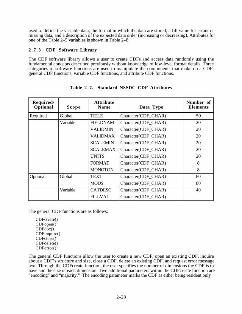
2–28
used to define the variable data, the format in which the data are stored, a fill value for errant ormissing data, and a description of the expected data order (increasing or decreasing). Attributes forone of the Table 2–5 variables is shown in Table 2–8.
2 . 7 . 3 CDF Software Library
The CDF software library allows a user to create CDFs and access data randomly using thefundamental concepts described previously without knowledge of low-level format details. Threecategories of software functions are used to manipulate the components that make up a CDF:general CDF functions, variable CDF functions, and attribute CDF functions.
Table 2–7. Standard NSSDC CDF Attributes
Required/Optional Scope
AttributeName Data_Type
Number ofElements
Required Global TITLE Character(CDF_CHAR) 50
Variable FIELDNAM
VALIDMIN
VALIDMAX
SCALEMIN
SCALEMAX
UNITS
FORMAT
MONOTON
Character(CDF_CHAR)
Character(CDF_CHAR)
Character(CDF_CHAR)
Character(CDF_CHAR)
Character(CDF_CHAR)
Character(CDF_CHAR)
Character(CDF_CHAR)
Character(CDF_CHAR)
20
20
20
20
20
20
8
8
Optional Global TEXT
MODS
Character(CDF_CHAR)
Character(CDF_CHAR)
80
80
Variable CATDESC
FILLVAL
Character(CDF_CHAR)
Character(CDF_CHAR)
40
The general CDF functions are as follows:
CDFcreate()CDFopen()CDFdoc()CDFinquire()CDFclose()CDFdelete()CDFerror()
The general CDF functions allow the user to create a new CDF, open an existing CDF, inquireabout a CDF’s structure and size, close a CDF, delete an existing CDF, and request error messagetext. Through the CDFcreate function, the user specifies the number of dimensions the CDF is tohave and the size of each dimension. Two additional parameters within the CDFcreate function are“encoding” and “majority.” The encoding parameter marks the CDF as either being resident only

2–29
Table 2–8. Time Variable Attributes
Attribute Value
FIELDNAM TIME
VALIDMIN 0000
VALIDMAX 2359
SCALEMIN 0100
SCALEMAX 0200
UNITS hours/minutes
FORMAT I4
MONOTON increase
FILLVAL -1
on the host processor or being transportable to other processors. The ordering of variable values inthe CDF by either row major or column major order is specified in the majority parameter.
The variable CDF functions are as follows:
CDFvarCreate()CDFvarNum()CDFvarRename()CDFvarInquire()CDFvarPut()CDFvarGet()CDFvarHyperPut()CDFvarHyperGet()
The variable functions allow the user to create a new variable, determine a variable’s identificationnumber, rename a variable, inquire about the characteristics of a variable (datatype, variances), put avariable data value into the CDF, and get a variable data value from the CDF. Variable data areinserted or retrieved from the CDF by referencing the appropriate variable, its dimension indices,and the record number. Furthermore, access calls are provided to allow for insertion of or retrievalof all the data elements for a specified variable record grid or subgrid.
The CDF attribute functions are as follows:CDFattrCreate()CDFattrNum()CDFattrInquire()CDFattrEntryInquire()CDFattrPut()CDFattrGet()
The attribute functions allow the user to create a new attribute, determine an attribute’s accessnumber, rename an attribute, inquire about a specific attribute or attribute entry, put values in anattribute and get values from an attribute. When creating an attribute, the user specifies whether theattribute describes a particular CDF variable or describes the CDF globally.

2–30
2 . 7 . 4 CDF Tools
Several tools have been devised to aid in creating and using CDFs. The skeleton table enables ascientist to specify the structure of a CDF without programming and allows the user to create askeleton CDF having no variable data. A CDF with all its metadata can be created by writing a textdefinition file, not a program, and then running a utility (CDFskeleton) that creates a CDF from thetext definition. The only source code required to complete a skeleton CDF is that necessary forreading input data and writing variable values to the CDF. Table 2–9 shows the text definition filethat would be created for the dataset in the previous example. This skeleton table file could then beused to create the skeleton CDF. A skeleton CDF is defined as any CDF whose definition iscomplete, but that does not yet contain values for all of its variables. A CDF has a completedefinition when
• Its dimensionality and dimension sizes are set.• All its variables are defined.• All its attributes are defined.• All its attributes have been assigned values.
For this example, the dimensionality is two and the sizes have been defined as two in eachdimension. The four variables have been named. The global and variable attributes have beennamed and the attributes contain legal values. The record variance and dimension variance for eachvariable also have been defined. The utility CDFskeleton can now accept this text file (Table 2–9)and create a completely formatted skeleton CDF (i.e., a CDF outline without data). The skeletonCDF can then be passed on to a programmer to write the necessary code to load data into the CDFvariables. The tool CDFinquire can be used to list the header, attribute definitions and values, andvariable definitions for the CDF. This includes the CDF dimension, the number of attributes, thenumber of variables, the majority, the record variance and the dimension variances for the variables;all those details provided by the scientist in the skeleton table text file. From this information, aprogrammer can ascertain how the variable data should be entered into the CDF. Once the data arein the CDF variables, the tool CDFbrowse can be used to display the variable values. CDFbrowseis a good tool to use for verifying that data have been correctly loaded into the CDF.
The CDFlist tool can be used to become acquainted with an existing CDF. CDFlist is designed toread user specified portions of a CDF. A user may specify a range on any variable in the CDF. Forexample, using the previous two-dimensional CDF, a user may wish to see data for a particular timeor data at only one of the two specified longitudes or latitudes. CDFlist allows the user to create asubset CDF using only the values specified in a selected range, as long as the range is specified fora variable which defines a CDF (i.e., time defines the number of records in the example CDF;longitude defines one dimension; and latitude defines another dimension). Selecting a range on avariable that has both record and dimension variance (i.e., temperature in the example CDF, isallowed but for output to a screen or file only, not for generating output to a CDF).
2 . 7 . 5 Sample CDF Skeleton
The KPGS Programmer’s Guide (Reference 6) contains an up-to-date sample key parameter CDFskeleton.

2–31
Table 2–9. Key Parameters Standards and Conventions
• Key parameter resolution is on the order of 1 minute (actually, many key parameters are timetagged using multiples of half the major frame rate of the spacecraft). Major frame rates areGEOTAIL, 16 seconds; WIND, 92 or 46 seconds; POLAR, 9.2 seconds; IMP-8,1.28 seconds and is generally time tagged to the middle of the measurement.
• Key parameter tag is presented in two separate representations in each key parameter record:– ISTP Standard Time (Time_PB5)—An intuitive representation (year, day, and elapsed
millisecond (ms) of day).– NSSDC Standard Time (Epoch)—A representation easy to use in computing and display,
elapsed ms since AD.• Missing or bad key parameters are represented with standard “fill” values.• Coordinate systems for key parameters are left to the discretion of the PI teams. Geocentric
Solar Eliptic (GSE) and Geocentric Solar Magnetospheric (GSM) are common systems usedby many of the key parameters.
• Externally generated key parameters always have spacecraft position and attitude embeddedin each key parameter record, if appropriate. Again, the particular coordinate system is left tothe discretion of the PI team.
• Each key parameter record contains quality information; also, the CDHF catalog storesquality information for each individual key parameter dataset.
• Each key parameter record contains a post-gap flag that explains, if appropriate, the reason agap in data coverage occurred.
• General key parameter datasets span 1 day.• All key parameter datasets (both external and internal) are presented as CDFs with detached
ISTP SFDUs.• Key parameter software is written in FORTRAN and/or C.
2 .8 ISTP Key Parameters
Note: This section was extracted from Reference 3.
It was recognized early that to accomplish ISTP scientific goals, the ability would be needed toquickly survey, in a coordinated and on-going fashion, the vast array of scientific data beinggathered by the instrumentation. Such a timely survey should reveal scientifically interestingphenomena (events) almost immediately and should be of great value during the scientificcampaigns. Thus, the concept of key parameters was born. In general, key parameters are low-resolution time series (on the order of 1 minute1) computed from each instrument. Key parameterscomputed internally to the CDHF are based on level-zero (decommutated telemetry) or SIRIUSdata (full GEOTAIL telemetry stream) as input. Key parameters also are generated externally to theCDHF that are ingested from a variety of ground-based instruments and non-ISTP spacecraft. Ingeneral, each key parameter dataset covers 1 complete day2. Internally generated key parameters
1 Actually, many spacecraft key parameters are time tagged using multiples of half the major framerate of the spacecraft. Major frame rates are GEOTAIL, 16 seconds; WIND, 92 or 46 seconds;POLAR, 9.2 seconds; IMP-8, 1.28 seconds.
2 Exceptions are key parameter datasets from IMP-8 which span approximately 1-week periodsand key parameter sets from some of the ground-based investigations.

2–32
are generally available within a few days of real time. The delay from real time for externallygenerated key parameters can range from near-real time to several weeks, depending on theirsource. Appendix A summarizes the set of key parameters understood as of this writing. Theresidency time for key parameter datasets on the CDHF storage is at least 90 days with CD-ROMcontaining the most recent 90 days of key parameters being generated by the DDF for distributionto the ISTP scientific community every 90 days. For rapid access, key parameters residing on theCDHF are also accessible via standard computer networks (both DECnet protocols and TCP/IP aresupported) approximately 1 hour after generation or ingestion into the CDHF.
Software for internally generated key parameter production is provided by the PI team for eachinstrument and is integrated into the CDHF production environment prior to the launch (in mostcases) of each spacecraft (GEOTAIL, WIND, POLAR, SOHO, and IMP-8). The first 6 monthsafter instrument activation3 is a period of time set aside to allow these PI teams to come to a betterunderstanding of the on-orbit operation of their instrumentation and thus refine the key parametersoftware appropriately. Because it is anticipated that additional refinement of the key parametersoftware will take place over the life of the ISTP mission, the CDHF environment has beendesigned to allow for rapid update of key parameter software and the ability to handle multipleversions of the same key parameter dataset, which can exist because of reprocessing.
Quality information is available for each key parameter dataset in the CDHF catalog and isembedded in the key parameter data records as a data element. All key parameter datasets arepresented as CDF files. Both internally and externally generated key parameter datasets adhere tomutually agreed on standards and conventions to permit rapid analysis and comparisons of themore than 100 key parameter datasets from a variety of instrumentation. The more important ofthese standards and conventions are listed in Table 2–9.
3 For example, GEOTAIL was launched July 1992, but all of the instrumentation was notactivated until September 1992.

3–1
SECTION 3—ISTP DATA FILE FORMATS
____________________________________________________________________________________________
This section describes the detailed formats of the data files provided to the investigators by eitherthe CDHF or the DDF. A detached ISTP SFDU header is associated with each of these files. Thedata files are as follows:
• Level-zero data files• SIRIUS formatted data files for GEOTAIL• Q/A files• Housekeeping data file• Command history file• Key parameter files• Definitive and predictive orbit data files• Definitive and predictive attitude data files
3 .1 Level-Zero Data Format
A level-zero data file contains the level-zero and instrument housekeeping data for one instrumentfor a given day. Level-zero data is created and provided for all WIND and POLAR instruments andapplicable GEOTAIL instruments.
Figure 3–1 shows the format of the level-zero data file. Each instrument level-zero data filecontains a file label record (FLR) and a variable number of data records, each containing a datarecord header (DRH), followed by one major frame’s worth of telemetry samples. Physical recordsize is fixed within a given instrument file but varies across instruments, depending on the numberof instrument sample words in a telemetry major frame. The minimum physical record size is 2792bytes, the minimum size of an FLR. The maximum physical record size is 32 kilobytes (kB).
The actual record size for a specific instrument file is determined by the number of bytes generatedby the instrument in a telemetry major frame plus the DRH. If this value is less than the minimumFLR size (2792 bytes), the physical record size is fixed at 2792 bytes, and the data records arezero-filled out to this length. If the major frame bytes plus the DRH size is within the 2792 byte-to-32-kB range, then the remaining unused part of the FLR is blank-filled to this size. If the majorframe bytes plus DRH size is greater than 32 kB, the logical record must be subdivided intomultiple physical records that conform to the 2792 byte-to-32-kB rule. Note that none of theinstruments onboard the GEOTAIL, WIND, or POLAR spacecraft generate so much telemetry datathat such subdivision of the logical records is necessary.
The number of data records varies with the period covered by the data and the quality of thetransmission. A production level-zero file spans a 24-hour, midnight-to-midnight Greenwich meantime (GMT) period. A quicklook level-zero file spans the first hour's worth of telemetry receivedduring a GEOTAIL contact.
Note that level-zero files for a instrument do not overlap. The first data record in a file contains thedata from the first major frame that began after midnight GMT; the last data record in the filecontains the data from the last major frame that began before midnight GMT. Thus, every record inthe file contains data for major frames that begin on the same day.
This section presents the formats of the level-zero data file FLR, DRH, and records for each of theGEOTAIL, WIND, and POLAR instruments.

3–2
File Label Record
Data Record 1
Data Record 2
Data Record 4
Data Record 3
Data Record n-1
Data Record n
::::
Data Record Header
Instrument Level-Zero Data From First Major Frame of Spacecraft Telemetry
Figure 3–1. Level–Zero Data File Format
3 . 1 . 1 Level-Zero Data File Label Record
An FLR is the first instrument level-zero file record following the ISTP data header. The FLRinformation occupies 2792 bytes. If the instrument data record (DRH plus the instrument data for amajor frame) size exceeds 2792 bytes, zeros (null) are used to fill the FLR out to the size of thedata record.
3.1.1.1 Level-Zero Data File Label Record Definition
Table 3–1 defines each field in the level-zero data file label record.
Table 3–1. Level-Zero Data File Label Record Definition (1 of 3)
Field Bytes Field Name Comments
1 0–3 Spacecraft ID (‘GEOTAIL’/‘WIND’/‘POLAR’)
2 4–7 Instrument Number
3 8–11 Instrument Name

3–3
Table 3–1. Level-Zero Data File Label Record Definition (2 of 3)
Field Bytes Field Name Comments
4 12–15 Physical Record Count (1) (first record)
5 16–19 Physical Records Per Major Frame (1)
6 20–23 Number of Physical Records in File
7 24–27 Major Frame Count—Beginning of First MajorFrame
8 28–31 Major Frame Count—Beginning of Last MajorFrame
9 32–39 Spacecraft Clock—Beginning of First MajorFrame
10 40–47 Spacecraft Clock—Beginning of Last MajorFrame
11 48–51 ATC:year—Beginning of First Major Frame
12 52–55 ATC:day—Beginning of First Major Frame
13 56–59 ATC:msec—Beginning of First Major Frame
14 60–63 ATC:µsec—Beginning of First Major Frame WIND/POLAR only
15 64–67 ATC:year—Beginning of Last Major Frame
16 68–71 ATC:day—Beginning of Last Major Frame
17 72–75 ATC:msec—Beginning of Last Major Frame
18 76–79 ATC:µsec—Beginning of Last Major Frame WIND/POLAR only
19 80–83 Number of Major Frames Expected
20 84–87 Number of Major Frames in File
21 88–91 Major Frame Level Gaps in Coverage
22 92–95 Data Coverage Type (‘PROD’ or ‘QL’)
23 96–99 Decommutation Rerun Number
24 100–107 Decommutation Program Version Number
25 108–115 Decommutation Characteristics DatabaseVersion Number
26 116–131 Decommutation Run Date/Time
27 132–175 Instrument Filename
28 176–179 Physical Record Length
29 180–199 Spares
30 200–203 Merge Rerun Number
31 204–211 Merge Program Version Number

3–4
Table 3–1. Level-Zero Data File Label Record Definition (3 of 3)
Field Bytes Field Name Comments
32 212–227 Merge Run Date/Time
33 228–231 Number of Edit Files (1–20)
34 232–275 Edit File 1-Edit Filename
35 276–299 Edit File 1-Edit Key
36 300–303 Edit File 1-Edit Rerun Number
37 304–311 Edit File 1-Edit Program Version Number
38 312–327 Edit File 1-Edit Run Date/Time
39 328–331 Edit File 1-Data Type (‘R/T’ or ‘P/B’)
40 332–359 Edit File 1-Message Key
41 360–403 Edit File 2-Edit Filename Same
– ..
.
.
166 2636–2663 Edit File 19-Message Key
167 2664–2707 Edit File 20-Edit Filename
168 2708–2731 Edit File 20-Edit Key
169 2732–2735 Edit File 20-Edit Rerun Number
170 2736–2743 Edit File 20-Edit Program Version Number
171 2744–2759 Edit File 20-Run Date/Time
172 2760–2763 Edit File 20-Data Type (‘R/T’ or ‘P/B’)
173 2764–2791 Edit File 20-Message key
174 2792–EOR Fill Bytes (if data record size exceeds 2792bytes)
3.1.1.2 Level-Zero Data File Label Record Field Descriptions
The following describes each FLR field:
Field Name: Spacecraft IDType/Length: Integer/4Values: 24 = GEOTAIL
25 = WIND26 = POLAR
Description: Identifies the spacecraft that transmitted the data contained in thisinstrument or housekeeping file.
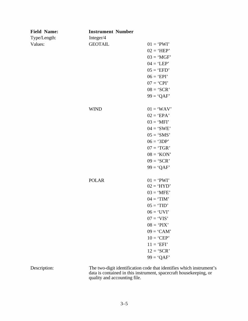
3–5
Field Name: Instrument NumberType/Length: Integer/4Values: GEOTAIL 01 = ‘PWI’
02 = ‘HEP’03 = ‘MGF’04 = ‘LEP’05 = ‘EFD’06 = ‘EPI’07 = ‘CPI’08 = ‘SCR’99 = ‘QAF’
WIND 01 = ‘WAV’02 = ‘EPA’03 = ‘MFI’04 = ‘SWE’05 = ‘SMS’06 = ‘3DP’07 = ‘TGR’08 = ‘KON’09 = ‘SCR’99 = ‘QAF’
POLAR 01 = ‘PWI’02 = ‘HYD’03 = ‘MFE’04 = ‘TIM’05 = ‘TID’06 = ‘UVI’07 = ‘VIS’08 = ‘PIX’09 = ‘CAM’10 = ‘CEP’11 = ‘EFI’12 = ‘SCR’99 = ‘QAF’
Description: The two-digit identification code that identifies which instrument’sdata is contained in this instrument, spacecraft housekeeping, orquality and accounting file.

3–6
Field Name: Instrument NameType/Length: Character/4Values: The values shown for the instrument numbers above correlate the
numbers to the instrument names.Description: The three-character code that identifies which instrument's data is
contained in this instrument or housekeeping file.
Field Name: Physical Record CountType/Length: Integer/4Value: 1Description: The relative position of this physical record within the instrument
or housekeeping file (i.e., the FLR is the first record in the file).
Field Name: Physical Records per Major FrameType/Length: Integer/4Value: 1Description: The number of physical data records in a major frame.
Field Name: Maximum Number of Physical Records in FileType/Length: Integer/4Values: GEOTAIL: D-2701
WIND: 1879*POLAR: 9392
Description: The maximum number of data records in an instrument orhousekeeping file (i.e., number of major frames/day plus 1 forFLR).*Note: The normal maximum number of records (major frames)
for the WIND spacecraft is about 940 (86,400 seconds/day, 92 seconds per major frame) with a data rate of5.56 kbps. Inside 60 Earth radii (Re), the possible datarate is 11.1 kbps. Refer to Reference 9 (WIND-POLARSIRD) for additional information.
Field Name: Major Frame Count—Beginning of 1st Major FrameType/Length: Integer/4Description: The major frame counter value at the beginning of the first major
frame (3 bits for GEOTAIL and 8 bits for WIND/POLAR).Note: The value for GEOTAIL is taken from the high-order 3 bits
of the subcommutated minor frame clock value in thetelemetry frame. All the subsequent beginning-of-major-frame values are from the spacecraft value in the majorframe.
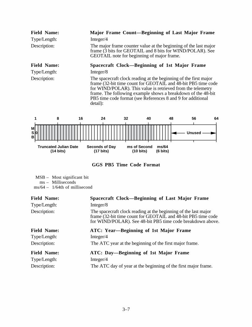
3–7
Field Name: Major Frame Count—Beginning of Last Major FrameType/Length: Integer/4Description: The major frame counter value at the beginning of the last major
frame (3 bits for GEOTAIL and 8 bits for WIND/POLAR). SeeGEOTAIL note for beginning of major frame.
Field Name: Spacecraft Clock—Beginning of 1st Major FrameType/Length: Integer/8Description: The spacecraft clock reading at the beginning of the first major
frame (32-bit time count for GEOTAIL and 48-bit PB5 time codefor WIND/POLAR). This value is retrieved from the telemetryframe. The following example shows a breakdown of the 48-bitPB5 time code format (see References 8 and 9 for additionaldetail):
Truncated Julian Date(14 bits)
Seconds of Day (17 bits)
ms of Second (10 bits)
ms/64(6 bits)
1 8 16 24 32 40 48 56 64
0 UnusedMSB
GGS PB5 Time Code Format
MSB – Most significant bitms – Milliseconds
ms/64 – 1/64th of millisecond
Field Name: Spacecraft Clock—Beginning of Last Major FrameType/Length: Integer/8Description: The spacecraft clock reading at the beginning of the last major
frame (32-bit time count for GEOTAIL and 48-bit PB5 time codefor WIND/POLAR). See 48-bit PB5 time code breakdown above.
Field Name: ATC: Year—Beginning of 1st Major FrameType/Length: Integer/4Description: The ATC year at the beginning of the first major frame.
Field Name: ATC: Day—Beginning of 1st Major FrameType/Length: Integer/4Description: The ATC day of year at the beginning of the first major frame.

3–8
Field Name: ATC: Msec—Beginning of 1st Major FrameType/Length: Integer/4Description: The ATC millisecond of day at the beginning of the first major
frame.
Field Name: ATC: µsec—Beginning of 1st Major FrameType/Length: Integer/4Description: The ATC microseconds at the beginning of the first major frame.
(Note that microsecond of day = 1000 * msec + µsec.) This field isfor WIND/POLAR only.
Field Name: ATC: Year—Beginning of Last Major FrameType/Length: Integer/4Description: The ATC year at the beginning of the last major frame.
Field Name: ATC: Day—Beginning of Last Major FrameType/Length: Integer/4Description: The ATC day of year at the beginning of the last major frame.
Field Name: ATC: Msec—Beginning of Last Major FrameType/Length: Integer/4Description: The ATC millisecond of day at the beginning of the last major
frame.
Field Name: ATC: µsec—Beginning of Last Major FrameType/Length: Integer/4Description: The ATC thousandths of millisecond (i.e., microseconds) at the
beginning of the last major frame. (Note that microsecond of day =1000 * msec + µsec.) This field is for WIND/POLAR only.
Field Name: Number of Major Frames ExpectedType/Length: Integer/4Description: The number of major frames expected in a 24-hour period.
Field Name: Number of Major Frames in FileType/Length: Integer/4Description: The actual number of major frames in this instrument or
housekeeping file.
Field Name: Major Frame Level Gaps in CoverageType/Length: Integer/4Description: The number of data gaps (each of which involves one or more
missing major frames).

3–9
Field Name: Data Coverage TypeType/Length: Character/4Value(s): ‘PROD’ or ‘QL’Description: The type of data coverage either production or quicklook.
Field Name: Decommutation Rerun NumberType/Length: Integer/4Description: The sequence number associated with the decommutation request.
Specifies the EDS software rerun number that produced thisinstrument file; EDS may be run a number of times on the sameinput data.
Field Name: Decommutation Program Version NumberType/Length: Character/8Description: The version number of the decommutation program used to create
this instrument or housekeeping file.
Field Name: Decommutation Characteristics Database VersionNumber
Type/Length: Character/8Description: The version number of the decommutation characteristics file used
to create this instrument or housekeeping file.
Field Name: Decommutation Run Date/TimeType/Length: Character/16Description: The local computer time (GMT) that this instrument or
housekeeping file was created. The format isYYYYDDDHHMMSSUUU, where
YYYY = four-digit year identifierDDD = three-digit day of yearHH = two-digit hour of dayMM = two-digit minute of hourSS = two-digit second of minuteUUU = three-digit millisecond of second
Field Name: Instrument FilenameType/Length: Character/44Description: The name associated with the instrument or housekeeping file
created by the decommutation function.
Field Name: Physical Record LengthType/Length: Integer/4Description: Number of bytes in a physical record. This value is equal to the
number of bytes per minor frame allocated to an instrumentmultiplied by the number of minor frames per major frame plus thelength in bytes of the data record header. Note that the minimumphysical record length is 2792 bytes.

3–10
Field Name: SparesType/Length: Character/20Description: Zero (null)-filled spare bytes.
Field Name: Merge Rerun NumberType/Length: Integer/4Description: The sequence number associated with the merge request.
Field Name: Merge Program Version NumberType/Length: Character/8Description: The version number of the merge program used to create this
instrument or housekeeping file.
Field Name: Merge Run Date/TimeType/Length: Character/16Description: The local computer time (GMT) that this merge file was created.
The format is YYYYDDDHHMMSSUUU, whereYYYY = four-digit year identifierDDD = three-digit day of yearHH = two-digit hour of dayMM = two-digit minute of hourSS = two-digit second of minuteUUU = three-digit millisecond of second
Field Name: Number of Edit FilesType/Length: Integer/4Value(s): 1 through 20 (end points inclusive)Description: The maximum number of edit files with major frames that are
within the requested timespan for a data group in the mergerequest.
Field Name: Edit File (n)—Edit FilenameType/Length: Character/44Description: Name of the nth edit file.
Field Name: Edit File (n)—Edit KeyType/Length: Character/24Description: The key for the edit file. The format is
EDITXXYYYYDDDHHMMSSVV, whereEDIT = ‘EDIT’XX = two-digit satellite codeYYYY = four-digit year identifier

3–11
DDD = three-digit day of yearHH = two-digit hour of dayMM = two-digit minute of hourSS = two-digit second of minuteVV = two-digit version number
Field Name: Edit File (n)—Edit Rerun NumberType/Length: Integer/4Description: The sequence number associated with the edit file for a specific
tape recorder dump or real-time pass.
Field Name: Edit File (n)—Edit Program Version NumberType/Length: Character/8Description: The version number of the edit program used to create this
instrument or housekeeping file.
Field Name: Edit File (n)—Edit Run Date/TimeType/Length: Character/16Description: The local computer time (GMT) that this edit file was created. The
format is YYYYDDDHHMMSSUUU, whereYYYY = four-digit year identifierDDD = three-digit day of yearHH = two-digit hour of dayMM = two-digit minute of hourSS = two-digit second of minuteUUU = three-digit millisecond of second
Field Name: Edit File (n)—Data TypeType/Length: Character/4Value(s): ‘P/B’ or ‘R/T’Description: The source of the edit file data was via playback transmission or
real time.
Field Name: Edit File (n)—Message KeyType/Length: Character/28Description: Key of the input message file in the following format:
NSSYYDDHHMMSSVV, whereN = one-character message key constant (“M”)SS = two-digit spacecraft identificationYY = two-digit year identifierDDD = three-digit day of yearHH = two-digit hour of dayMM = two-digit minute of hourSS = two-digit second of minuteVV = two-digit version number

3–12
3.1.1.3 FLR Fields Loaded by NRT Subsystem
The Near-Real-Time (NRT) subsystem of the CDHF generates level-zero data files on the CDHFusing data it receives in near-real time from the GDCF. The user may retrieve this data via the userinterface. The NRT loads the following FLR fields: 1 through 20, 22, 26, 27, and 28.
3 . 1 . 2 Level-Zero Data Record Header
Each data record in a level-zero data file begins with a DRH. Note that the minor frame quality field(last field) consists of 1 byte of quality flags for each minor frame. This section defines anddescribes the DRH.
3.1.2.1 Level-Zero Data Record Header Definition
Table 3–2 defines each field in the DRH of the level-zero data file.
Table 3–2. Data Record Header Definition
Field Bytes Field Name Comments
1 0–3 Instrument Number
2 4–7 Physical Record Number Within File
3 8–11 Major Frame Count—Beginning of Major Frame
4 12–19 Spacecraft Clock—Beginning of Major Frame
5 20–23 ATC:year—Beginning of Major Frame
6 24–27 ATC:day—Beginning of Major Frame
7 28–31 ATC:msec—Beginning of Major Frame
8 32–35 ATC:µsec—Beginning of Major Frame WIND/POLARonly
9 36–39 Number of Minor Frames With Fill
10 40–43 Number of Minor Frames With Frame Sync Error
11 44–47 Telemetry Mode Indicator
12 48–559 Minor Frame Quality (GEOTAIL)
48–299 Minor Frame Quality (WIND/POLAR)

3–13
3.1.2.2 Level-Zero Record Header Field Descriptions
The following information describes each DRH field:
Field Name: Instrument NumberType/Length: Integer/4Value(s): Refer to instrument numbers in the FLR description.Description: The two-digit code that identifies which instrument's data is
contained in this instrument or housekeeping file.
Field Name: Physical Record Number Within FileType/Length: Integer/4Value(s): GEOTAIL: up to 2701
WIND: up to 1879 (Note: Refer to maximum number of physicalrecords in file note in FLR description.)POLAR: up to 9392
Description: The relative position of this record with the ISTP data header isrecord 1 in the instrument or housekeeping file where the FLR isrecord 1, the first data record is record 2, and the nth data record isrecord n + 1.
Field Name: Major Frame Count—Beginning of Major FrameType/Length: Integer/4Description: The major frame counter value at the beginning of the major frame
(22 bits for GEOTAIL and 8 bits for WIND/POLAR). See notes inFLR major frame count.
Field Name: Spacecraft Clock—Beginning of 1st Major FrameType/Length: Integer/8Description: The spacecraft clock reading at the beginning of the major frame
(32-bit time count for GEOTAIL, and 56-bit PB5 time code forWIND/POLAR). See the example in FLR spacecraft clock field forbreakdown of the 56-bit PB5 time code.
Field Name: ATC: Year—Beginning of Major FrameType/Length: Integer/4Description: The ATC year at the beginning of the major frame.
Field Name: ATC: Day—Beginning of Major FrameType/Length: Integer/4Description: The ATC day of year at the beginning of the major frame.
Field Name: ATC: Msec—Beginning of Major FrameType/Length: Integer/4Description: The ATC millisecond of day at the beginning of the major frame.
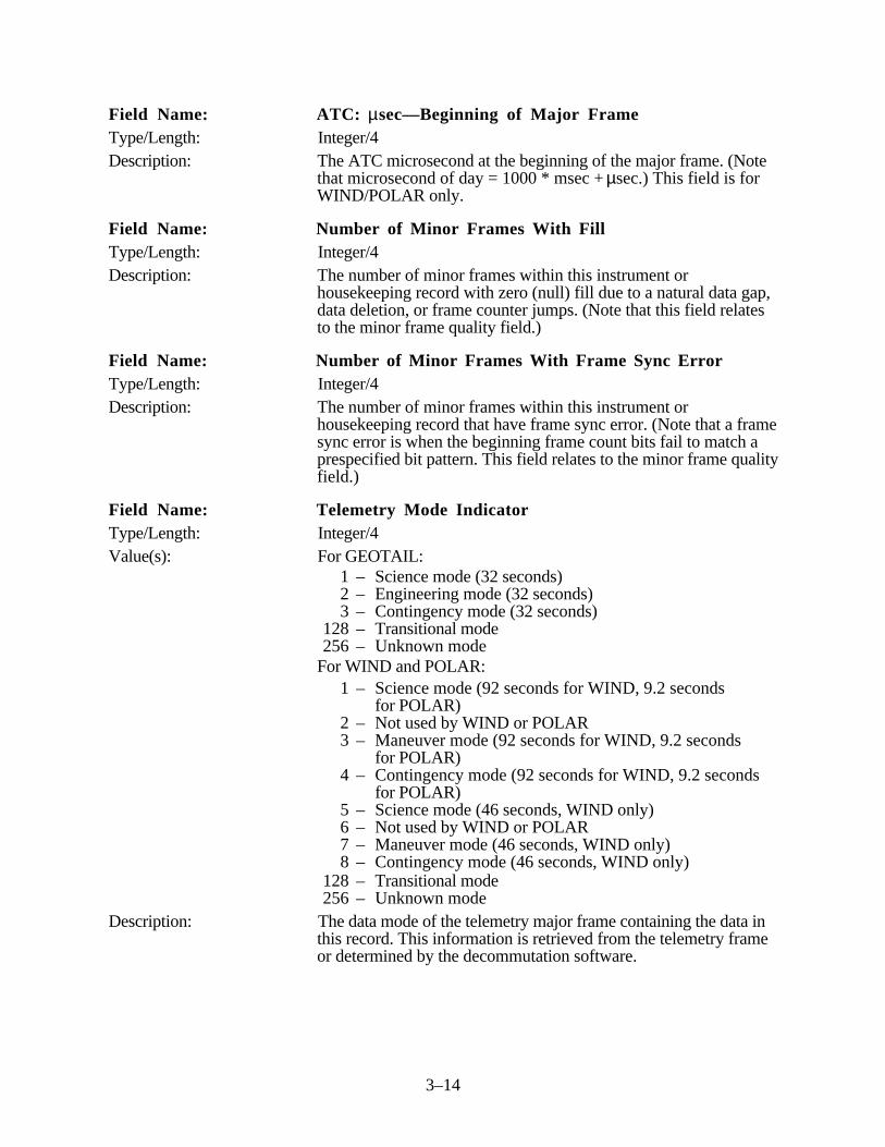
3–14
Field Name: ATC: µsec—Beginning of Major FrameType/Length: Integer/4Description: The ATC microsecond at the beginning of the major frame. (Note
that microsecond of day = 1000 * msec + µsec.) This field is forWIND/POLAR only.
Field Name: Number of Minor Frames With FillType/Length: Integer/4Description: The number of minor frames within this instrument or
housekeeping record with zero (null) fill due to a natural data gap,data deletion, or frame counter jumps. (Note that this field relatesto the minor frame quality field.)
Field Name: Number of Minor Frames With Frame Sync ErrorType/Length: Integer/4Description: The number of minor frames within this instrument or
housekeeping record that have frame sync error. (Note that a framesync error is when the beginning frame count bits fail to match aprespecified bit pattern. This field relates to the minor frame qualityfield.)
Field Name: Telemetry Mode IndicatorType/Length: Integer/4Value(s): For GEOTAIL:
1 – Science mode (32 seconds)2 – Engineering mode (32 seconds)3 – Contingency mode (32 seconds)
128 – Transitional mode256 – Unknown mode
For WIND and POLAR:1 – Science mode (92 seconds for WIND, 9.2 seconds
for POLAR)2 – Not used by WIND or POLAR3 – Maneuver mode (92 seconds for WIND, 9.2 seconds
for POLAR)4 – Contingency mode (92 seconds for WIND, 9.2 seconds
for POLAR)5 – Science mode (46 seconds, WIND only)6 – Not used by WIND or POLAR7 – Maneuver mode (46 seconds, WIND only)8 – Contingency mode (46 seconds, WIND only)
128 – Transitional mode256 – Unknown mode
Description: The data mode of the telemetry major frame containing the data inthis record. This information is retrieved from the telemetry frameor determined by the decommutation software.

3–15
Field Name: Minor Frame QualityType/Length: Integer/4Description: One byte of quality flags for each minor frame. The flags indicate
whether the corresponding minor frame has fill, a frame countererror, or a frame/sync error (128 words for GEOTAIL and 63words for WIND/POLAR). Since 63 words equals 252 bytes andthere are only 250 minor frames in a WIND or POLAR majorframe, the last 2 bytes in the WIND/POLAR DRH are zero-filled.If a quality byte is zero-filled, no errors were detected in thecorresponding minor frame. A bit set to “1” indicates an error. Thefollowing diagram identifies the specific error associated with eachbit:
7 6 5 4 3 2 1 0
bit 0 = frame sync error flagbit 1 = frame counters error flagbit 2 = fill frame flagbit 3–7 = spares
Thus, if the number “2” bit is set to “1”, the corresponding minorframe is filled with zeros because of missing or unreadable data.
3 . 1 . 3 Level-Zero Data Subrecord Formats
The data (nonheader) part of each level-zero-processed data record for a given instrument issubdivided into fixed-length subrecords, each containing that instrument’s instrument data andinstrument housekeeping data from a minor (sub) frame. The length of the subrecord depends onthe number of minor frame bytes allocated to the instrument, including subcommutated (sometimescalled loose) bytes. Whenever a housekeeping or subcommutated byte is not allocated to theinstrument, a zero-filled byte is inserted into the subrecord instead.
The total length of the record in bytes is the number of bytes per subrecord times the number ofminor frames per major frame plus the DRH length plus any additional bytes needed to pad therecord to the 4-byte word boundary. As indicated in Section 3.1, the minimum data record size is2792 bytes, which is the minimum size of an FLR. Note that for WIND/POLAR instruments theDRH is 300 bytes long and there are 250 minor frames per major frame. For GEOTAIL the DRHis 560 bytes long and there are 512 minor frames per major frame.
A zero-filled subrecord is put in the output data record when the associated input minor frame ismissing or cannot be interpreted. The DRH contains 1 byte of quality flags for each minor frame(subrecord). One quality flag indicates whether the associated subrecord is filled with zeros. Otherquality flags denote frame counter and frame synchronization errors. The statistical information inthe Q/A file record associated with a major frame also indicates which minor frames (subrecords)are zero-filled.
The ISTP GDPS never outputs an entire major frame of zero fill. Thus, if the entire major frame ismissing from the input or is not interpretable, the result will be a time gap in the output. The Q/Afile indicates which major frames are missing. A missing major frame also can be determined bycomparing the major frame count in the DRH of the previous data record to that of the current datarecord. The frame count increases monotonically from one record to the next when there is no gapbetween them.
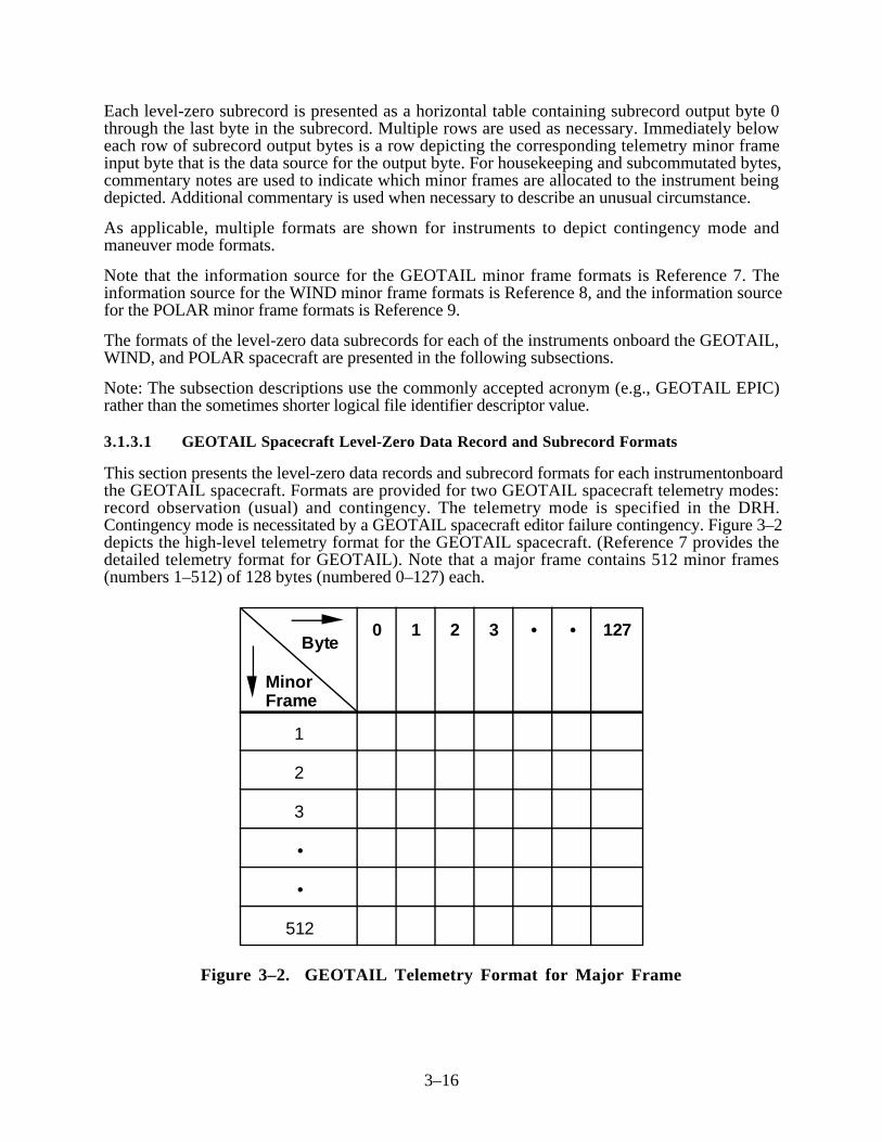
3–16
Each level-zero subrecord is presented as a horizontal table containing subrecord output byte 0through the last byte in the subrecord. Multiple rows are used as necessary. Immediately beloweach row of subrecord output bytes is a row depicting the corresponding telemetry minor frameinput byte that is the data source for the output byte. For housekeeping and subcommutated bytes,commentary notes are used to indicate which minor frames are allocated to the instrument beingdepicted. Additional commentary is used when necessary to describe an unusual circumstance.
As applicable, multiple formats are shown for instruments to depict contingency mode andmaneuver mode formats.
Note that the information source for the GEOTAIL minor frame formats is Reference 7. Theinformation source for the WIND minor frame formats is Reference 8, and the information sourcefor the POLAR minor frame formats is Reference 9.
The formats of the level-zero data subrecords for each of the instruments onboard the GEOTAIL,WIND, and POLAR spacecraft are presented in the following subsections.
Note: The subsection descriptions use the commonly accepted acronym (e.g., GEOTAIL EPIC)rather than the sometimes shorter logical file identifier descriptor value.
3.1.3.1 GEOTAIL Spacecraft Level-Zero Data Record and Subrecord Formats
This section presents the level-zero data records and subrecord formats for each instrumentonboardthe GEOTAIL spacecraft. Formats are provided for two GEOTAIL spacecraft telemetry modes:record observation (usual) and contingency. The telemetry mode is specified in the DRH.Contingency mode is necessitated by a GEOTAIL spacecraft editor failure contingency. Figure 3–2depicts the high-level telemetry format for the GEOTAIL spacecraft. (Reference 7 provides thedetailed telemetry format for GEOTAIL). Note that a major frame contains 512 minor frames(numbers 1–512) of 128 bytes (numbered 0–127) each.
0 1 2 3 • • 127
1
2
3
•
•
512
Byte
Minor Frame
Figure 3–2. GEOTAIL Telemetry Format for Major Frame

3–17
Note that the following sections specify for each instrument onboard the GEOTAIL spacecraftwhich telemetry bytes of each minor frame are allocated to the instrument. For example, in therecord observation mode, the following eight bytes of each minor frame of telemetry are allocatedto the EFD instrument: 16, 17, 18, 19, 20, 21, 22, and 23. These sections also relate thesetelemetry bytes to the level-zero data record for the instrument. Note that the telemetry handbookthat defines the telemetry fields for GEOTAIL is a TBS.
3.1.3.1.1 EFD Instrument Level-Zero Data Record and Subrecord Formats
This section presents the level-zero data records and subrecord formats for the GEOTAIL EFDinstrument.
3.1.3.1.1.1 EFD Instrument Record Observation Data Record and Subrecord Formats
The EFD instrument generates 8 bytes of telemetry in each GEOTAIL minor frame duringGEOTAIL record observation mode. The following is the format of the level-zero-processed EFDdata record for the GEOTAIL record observation mode.
Item Description Length(bytes)
Record(bytes)
1 Data record header 560 0–559
2 Subrecord 1 containing EFD level-zero data fromGEOTAIL minor frame 1
8 560–567
3 Subrecord 2 containing EFD level-zero data fromGEOTAIL minor frame 2
8 568–575
4–512 Subrecord 3–511 containing EFD level-zero data fromGEOTAIL minor frames 3–511
4072 576–4647
513 Subrecord 512 containing EFD level-zero data fromGEOTAIL minor frame 512
8 4648–4655
Total record length: 4656 bytes (1164 words)
The EFD instrument record observation subrecord format consists of an 8-byte logical subrecordfor each minor frame in a major frame of telemetry. These 8 bytes correspond to the indicated8 minor frame bytes of the GEOTAIL spacecraft record observation telemetry format.
Subrecord Output Byte 0 1 2 3 4 5 6 7
Telemetry Minor Frame Byte 16 17 18 19 20 21 22 23
Note that through the remainder of this DFCD, the terms subrecord output byte and telemetryminor frame byte are abbreviated to subrecord output byte and minor frame input byte.
3.1.3.1.1.2 EFD Instrument Contingency Data Record and Subrecord Formats
The EFD instrument generates 15 bytes of telemetry in each GEOTAIL minor frame duringGEOTAIL contingency mode. The following is the format of the level-zero-processed EFD datarecord for the GEOTAIL contingency mode.

3–18
Item Description Length(bytes)
Record(bytes)
1 Data record header 560 0–559
2 Subrecord 1 containing EFD level-zero data fromGEOTAIL minor frame 1
15 560–574
3 Subrecord 2 containing EFD level-zero data fromGEOTAIL minor frame 2
15 575–589
4–512 Subrecord 3–511 containing EFD level-zero data fromGEOTAIL minor frames 3–511
7635 590–8224
513 Subrecord 512 containing EFD level-zero data fromGEOTAIL minor frame 512
15 8225–8239
Total record length: 8240 bytes (2060 words)
The EFD instrument contingency subrecord format consists of a 15-byte logical subrecord for eachminor frame in a major frame of telemetry. These 15 bytes correspond to the indicated 15 minorframe bytes of the GEOTAIL spacecraft contingency telemetry format.
Subrecord Output Byte 0 1 2 3 4 5 6 7
Minor Frame Input Byte 16 17 18 19 66 67 68 69
Subrecord Output Byte 8 9 10 11 12 13 14
Minor Frame Input Byte 70 71 72 73 74 75 76
3.1.3.1.2 MGF Instrument Level-Zero Data Records and Subrecord Formats
This section presents the level-zero data records and subrecord formats for the GEOTAIL MGFinstrument.
3.1.3.1.2.1 MGF Instrument Record Observation Data Record and Subrecord Formats
The MGF instrument generates 8 bytes of telemetry in each GEOTAIL minor frame duringGEOTAIL record observation mode. The following is the format of the level-zero processed MGFdata record for the GEOTAIL record observation mode.
Item Description Length(bytes)
Record(bytes)
1 Data record header 560 0–559
2 Subrecord 1 containing MGF level-zero data fromGEOTAIL minor frame 1
8 560–567
3 Subrecord 2 containing MGF level-zero data fromGEOTAIL minor frame 2
8 568–575

3–19
Item Description Length(bytes)
Record(bytes)
4–512 Subrecord 3–511 containing MGF level-zero data fromGEOTAIL minor frames 3–511
4072 576–4647
513 Subrecord 512 containing MGF level-zero data fromGEOTAIL minor frame 512
8 4648–4655
Total record length: 4656 bytes (1164 words)
The MGF instrument record observation subrecord format consists of an 8-byte logical subrecordfor each minor frame in a major frame of telemetry. These 8 bytes correspond to the indicated8 minor frame bytes of the GEOTAIL spacecraft record observation telemetry format.
Subrecord Output Byte 0 1 2 3 4 5 6 7
Minor Frame Input Byte 24 25 26 27 28 29 30 31
3.1.3.1.2.2 MGF Instrument Contingency Data Record and Subrecord Formats
The MGF instrument generates 12 bytes of telemetry in each GEOTAIL minor frame duringGEOTAIL contingency mode. The following is the format of the level-zero-processed MGF datarecord for the GEOTAIL contingency mode.
Item Description Length(bytes)
Record(bytes)
1 Data record header 560 0–559
2 Subrecord 1 containing MGF level-zero data fromGEOTAIL minor frame 1
12 560–571
3 Subrecord 2 containing MGF level-zero data fromGEOTAIL minor frame 2
12 572–583
4–512 Subrecord 3–511 containing MGF level-zero data fromGEOTAIL minor frames 3–511
6108 584–6691
513 Subrecord 512 containing MGF level-zero data fromGEOTAIL minor frame 512
12 6692–6703
Total record length: 6704 bytes (1676 words)
The MGF instrument contingency subrecord format consists of a 12-byte logical subrecord foreach minor frame in a major frame of telemetry. These 12 bytes correspond to the indicated12 minor frame bytes of the GEOTAIL spacecraft contingency telemetry format.
Subrecord Output Byte 0 1 2 3 4 5 6 7 8 9 10 11
Minor Frame Input Byte 20 21 22 23 24 25 26 27 28 29 64 65

3–20
3.1.3.1.3 LEP Instrument Level-Zero Data Record and Subrecord Formats
This section presents the level-zero data record and subrecord formats for the GEOTAIL LEPinstrument.
3.1.3.1.3.1 LEP Instrument Record Observation Data Record and Subrecord Formats
The LEP instrument generates 16 bytes of telemetry in each GEOTAIL minor frame duringGEOTAIL record observation mode. The following is the format of the level-zero-processed LEPdata record for the GEOTAIL record observation mode.
Item Description Length(bytes)
Record(bytes)
1 Data record header 560 0–559
2 Subrecord 1 containing LEP level-zero data fromGEOTAIL minor frame 1
16 560–575
3 Subrecord 2 containing LEP level-zero data fromGEOTAIL minor frame 2
16 576–591
4–512 Subrecord 3–511 containing LEP level-zero data fromGEOTAIL minor frames 3–511
8144 592–8735
513 Subrecord 512 containing LEP level-zero data fromGEOTAIL minor frame 512
16 8736–8751
Total record length: 8752 bytes (2188 words)
The LEP instrument record observation subrecord format consists of a 16-byte logical subrecordfor each minor frame in a major frame of telemetry. These 16 bytes correspond to the indicated16 minor frame bytes of the GEOTAIL spacecraft record observation telemetry format.
Subrecord Output Byte 0 1 2 3 4 5 6 7 8
Minor Frame Input Byte 32 33 34 35 36 37 38 39 40
Subrecord Output Byte 9 10 11 12 13 14 15
Minor Frame Input Byte 41 42 43 44 45 46 47
3.1.3.1.3.2 LEP Instrument Contingency Data Record and Subrecord Formats
The LEP instrument generates 27 bytes of telemetry in each GEOTAIL minor frame duringGEOTAIL contingency mode. The following is the format of the level-zero-processed LEP datarecord for the GEOTAIL contingency mode.

3–21
Item Description Length(bytes)
Record(bytes)
1 Data record header 560 0–559
2 Subrecord 1 containing LEP level-zero data fromGEOTAIL minor frame 1
27 560–586
3 Subrecord 2 containing LEP level-zero data fromGEOTAIL minor frame 2
27 587–613
4–512 Subrecord 3–511 containing LEP level-zero data fromGEOTAIL minor frames 3–511
13,743 614–14,356
513 Subrecord 512 containing LEP level-zero data fromGEOTAIL minor frame 512
27 14,357–14,383
Total record length: 14,384 bytes (3596 words)
The LEP instrument contingency subrecord format consists of a 27-byte logical subrecord for eachminor frame in a major frame of telemetry. These 27 bytes correspond to the indicated 27 minorframe bytes of the GEOTAIL spacecraft contingency telemetry format.
Subrecord Output Byte 0 1 2 3 4 5 6 7 8 9 10 11
Minor Frame Input Byte 37 38 39 40 41 42 43 44 45 46 47 48
Subrecord Output Byte 12 13 14 15 16 17 18 19 20 21 22 23
Minor Frame Input Byte 49 50 51 52 53 54 55 56 57 58 59 60
Subrecord Output Byte 24 25 26
Minor Frame Input Byte 61 62 63
3.1.3.1.4 HEP Instrument Level-Zero Data Record and Subrecord Formats
This section presents the level-zero data record and subrecord formats for the GEOTAIL HEPinstrument.
3.1.3.1.4.1 HEP Instrument Record Observation Data Record and Subrecord Formats
The HEP instrument generates 13 bytes of telemetry in each GEOTAIL minor frame duringGEOTAIL record observation mode. The following is the format of the level-zero-processed HEPdata record for the GEOTAIL record observation mode.

3–22
Item Description Length(bytes)
Record(bytes)
1 Data record header 560 0–559
2 Subrecord 1 containing HEP level-zero data fromGEOTAIL minor frame 1
13 560–572
3 Subrecord 2 containing HEP level-zero data fromGEOTAIL minor frame 2
13 573–585
4–512 Subrecord 3–511 containing HEP level-zero data fromGEOTAIL minor frames 3–511
6617 586–7202
513 Subrecord 512 containing HEP level-zero data fromGEOTAIL minor frame 512
13 7203–7215
Total record length: 7216 bytes (1804 words)
The HEP instrument record observation subrecord format consists of a 13-byte logical subrecordfor each minor frame in a major frame of telemetry. These 13 bytes correspond to the indicated13 minor frame bytes of the GEOTAIL spacecraft record observation telemetry format.
Subrecord Output Byte 0 1 2 3 4 5 6 7 8 9 10 11 12
Minor Frame Input Byte 48 49 50 51 52 53 54 55 56 57 58 59 60
3.1.3.1.4.2 HEP Instrument Contingency Data Record and Subrecord Formats
The HEP instrument generates 15 bytes of telemetry in each GEOTAIL minor frame duringGEOTAIL contingency mode. The following is the format of the level-zero-processed HEP datarecord for the GEOTAIL contingency mode.
Item Description Length(bytes)
Record(bytes)
1 Data record header 560 0–559
2 Subrecord 1 containing HEP level-zero data fromGEOTAIL minor frame 1
15 560–574
3 Subrecord 2 containing HEP level-zero data fromGEOTAIL minor frame 2
15 575–589
4–512 Subrecord 3–511 containing HEP level-zero data fromGEOTAIL minor frames 3–511
7635 590–8224
513 Subrecord 512 containing HEP level-zero data fromGEOTAIL minor frame 512
15 8225–8239
Total record length: 8240 bytes (2060 words)

3–23
The HEP instrument contingency subrecord format consists of a 15-byte logical subrecord for eachminor frame in a major frame of telemetry. These 15 bytes correspond to the indicated 15 minorframe bytes of the GEOTAIL spacecraft contingency telemetry format.
Subrecord Output Byte 0 1 2 3 4 5 6 7 8
Minor Frame Input Byte 77 78 79 80 81 82 83 84 85
Subrecord Output Byte 9 10 11 12 13 14
Minor Frame Input Byte 86 87 88 89 90 91
3.1.3.1.5 PWI Level-Zero Data Record and Subrecord Formats
This section presents the level-zero data record and subrecord formats for the GEOTAIL PWIinstrument.
3.1.3.1.5.1 PWI Record Observation Data Record and Subrecord Formats
The PWI generates 11 bytes of telemetry in each GEOTAIL minor frame during GEOTAIL recordobservation mode. The following is the format of the level-zero-processed PWI data record for theGEOTAIL record observation mode.
Item Description Length(bytes)
Record(bytes)
1 Data record header 560 0–559
2 Subrecord 1 containing PWI level-zero data fromGEOTAIL minor frame 1
11 560–570
3 Subrecord 2 containing PWI level-zero data fromGEOTAIL minor frame 2
11 571–581
4–512 Subrecord 3–511 containing PWI level-zero data fromGEOTAIL minor frames 3–511
5599 582–6180
513 Subrecord 512 containing PWI level-zero data fromGEOTAIL minor frame 512
11 6181–6191
Total record length: 6192 bytes (1548 words)
The PWI record observation subrecord format consists of an 11-byte logical subrecord for eachminor frame in a major frame of telemetry. These 11 bytes correspond to the indicated 11 minorframe bytes of the GEOTAIL spacecraft record observation telemetry format.
Subrecord Output Byte 0 1 2 3 4 5 6 7 8 9 10
Minor Frame Input Byte 61 62 63 64 65 66 67 68 69 70 71

3–24
3.1.3.1.5.2 PWI Contingency Data Record and Subrecord Formats
The PWI generates 29 bytes of telemetry in each GEOTAIL minor frame during GEOTAILcontingency mode. The following is the format of the level-zero-processed PWI data record for theGEOTAIL contingency mode.
Item Description Length(bytes)
Record(bytes)
1 Data record header 560 0–559
2 Subrecord 1 containing PWI level-zero data fromGEOTAIL minor frame 1
29 560–588
3 Subrecord 2 containing PWI level-zero data fromGEOTAIL minor frame 2
29 589–617
4–512 Subrecord 3–511 containing PWI level-zero data fromGEOTAIL minor frames 3–511
14,761 618–15,378
513 Subrecord 512 containing PWI level-zero data fromGEOTAIL minor frame 512
29 15,379–15,407
Total record length: 15,408 bytes (3852 words)
The PWI contingency subrecord format consists of a 29-byte logical subrecord for each minorframe in a major frame of telemetry. These 29 bytes correspond to the indicated 29 minor framebytes of the GEOTAIL spacecraft contingency telemetry format.
Subrecord Output Byte 0 1 2 3 4 5 6 7 8 9 10
Minor Frame Input Byte 30 31 32 33 34 35 36 92 93 94 95
Subrecord Output Byte 11 12 13 14 15 16 17 18 19 20 21
Minor Frame Input Byte 96 97 98 99 100 101 102 103 104 105 106
Subrecord Output Byte 22 23 24 25 26 27 28
Minor Frame Input Byte 107 108 109 110 111 112 113
3.1.3.1.6 CPI Instrument Level-Zero Data Record and Subrecord Formats
This section presents the level-zero data record and subrecord formats for the GEOTAIL CPIinstrument.
3.1.3.1.6.1 CPI Instrument Record Observation Data Record and Subrecord Formats
The CPI instrument generates 36 bytes of telemetry in each GEOTAIL minor frame duringGEOTAIL record observation mode. The following is the format of the level-zero-processed CPIdata record for the GEOTAIL record observation mode.

3–25
Item Description Length(bytes)
Record(bytes)
1 Data record header 560 0–559
2 Subrecord 1 containing CPI level-zero data fromGEOTAIL minor frame 1
36 560–595
3 Subrecord 2 containing CPI level-zero data fromGEOTAIL minor frame 2
36 596–631
4–512 Subrecord 3–511 containing CPI level-zero data fromGEOTAIL minor frames 3–511
18,324 632–18,955
513 Subrecord 512 containing CPI level-zero data fromGEOTAIL minor frame 512
36 18,956–18,991
Total record length: 18,992 bytes (4748 words)
The CPI instrument record observation subrecord format consists of a 36-byte logical subrecordfor each minor frame in a major frame of telemetry. These 36 bytes correspond to the indicated36 minor frame bytes of the GEOTAIL spacecraft record observation telemetry format.
Subrecord Output Byte 0 1 2 3 4 5 6 7 8 9 10 11
Minor Frame Input Byte 72 73 74 75 76 77 78 79 80 81 82 83
Subrecord Output Byte 12 13 14 15 16 17 18 19 20 21 22 23
Minor Frame Input Byte 84 85 86 87 88 89 90 91 92 93 94 95
Subrecord Output Byte 24 25 26 27 28 29 30 31 32 33 34 35
Minor Frame Input Byte 96 97 98 99 100 101 102 103 104 105 106 107
3.1.3.1.6.2 CPI Instrument Contingency Data Record and Subrecord Formats
The CPI instrument generates 9 bytes of telemetry in each GEOTAIL minor frame duringGEOTAIL contingency mode. The following is the format of the level-zero-processed CPI datarecord for the GEOTAIL contingency mode.
Item Description Length(bytes)
Record(bytes)
1 Data record header 560 0–559
2 Subrecord 1 containing CPI level-zero data from GEOTAILminor frame 1
9 560–568
3 Subrecord 2 containing CPI level-zero data from GEOTAILminor frame 2
9 569–577

3–26
Item Description Length(bytes)
Record(bytes)
4–512 Subrecord 3–511 containing CPI level-zero data fromGEOTAIL minor frames 3–511
4581 578–5158
513 Subrecord 512 containing CPI level-zero data fromGEOTAIL minor frame 512
9 5159–5167
Total record length: 5168 bytes (1292 words)
The CPI instrument contingency subrecord format consists of a 9-byte logical subrecord for eachminor frame in a major frame of telemetry. These 9 bytes correspond to the indicated 9 minorframe bytes of the GEOTAIL spacecraft contingency telemetry format.
Subrecord Output Byte 0 1 2 3 4 5 6 7 8
Minor Frame Input Byte 114 115 116 117 118 119 120 121 122
3.1.3.1.7 EPIC Instrument Level-Zero Data Record and Subrecord Formats
This section presents the level-zero data record and subrecord formats for the GEOTAIL EPICinstrument.
3.1.3.1.7.1 EPIC Instrument Record Observation Data Record and Subrecord Formats
The EPIC instrument generates 20 bytes of telemetry in each GEOTAIL minor frame duringGEOTAIL record observation mode. The following is the format of the level-zero-processed EPICdata record for the GEOTAIL record observation mode.
Item Description Length(bytes)
Record(bytes)
1 Data record header 560 0–559
2 Subrecord 1 containing EPIC level-zero data fromGEOTAIL minor frame 1
20 560–579
3 Subrecord 2 containing EPIC level-zero data fromGEOTAIL minor frame 2
20 580–599
4–512 Subrecord 3–511 containing EPIC level-zero data fromGEOTAIL minor frames 3–511
10,180 600–10,779
513 Subrecord 512 containing EPIC level-zero data fromGEOTAIL minor frame 512
20 10,780–10,799
Total record length: 10,800 bytes (2700 words)
The EPIC instrument record observation subrecord format consists of a 20-byte logical subrecordfor each minor frame in a major frame of telemetry. These 20 bytes correspond to the indicated20 minor frame bytes of the GEOTAIL spacecraft record observation telemetry format.

3–27
Subrecord Output Byte 0 1 2 3 4 5 6 7 8 9
Minor Frame Input Byte 108 109 110 111 112 113 114 115 116 117
Subrecord Output Byte 10 11 12 13 14 15 16 17 18 19
Minor Frame Input Byte 118 119 120 121 122 123 124 125 126 127
3.1.3.1.7.2 EPIC Instrument Contingency Data Record and Subrecord Formats
The EPIC instrument generates 5 bytes of telemetry in each GEOTAIL minor frame duringGEOTAIL contingency mode. The following is the format of the level-zero-processed EPIC datarecord for the GEOTAIL contingency mode.
Item Description Length(bytes)
Record(bytes)
1 Data record header 560 0–559
2 Subrecord 1 containing EPIC level-zero data fromGEOTAIL minor frame 1
5 560–564
3 Subrecord 2 containing EPIC level-zero data fromGEOTAIL minor frame 2
5 565–569
4–512 Subrecord 3–511 containing EPIC level-zero data fromGEOTAIL minor frames 3–511
2545 570–3114
513 Subrecord 512 containing EPIC level-zero data fromGEOTAIL minor frame 512
5 3115–3119
Total record length: 3120 bytes (780 words)
The EPIC instrument contingency subrecord format consists of a 5-byte logical subrecord for eachminor frame in a major frame of telemetry. These 5 bytes correspond to the indicated 5 minorframe bytes of the GEOTAIL spacecraft contingency telemetry format.
Subrecord Output Byte 0 1 2 3 4
Minor Frame Input Byte 123 124 125 126 127
3.1.3.2 WIND Spacecraft Level-Zero Data Record and Subrecord Formats
This section presents the level-zero data record and subrecord formats for each instrument onboardthe WIND spacecraft.
Formats are provided for two WIND spacecraft telemetry modes: science telemetry (usual) andmaneuver. Note that the formats used in WIND contingency science telemetry modeare identical to those used in WIND science mode. The telemetry mode is indicated in theDRH. Maneuver mode is used when the WIND spacecraft attitude control is not sufficiently stable

3–28
to permit accurate attitude determination for normal science data collection. In this mode, the spinrate varies and the spacecraft attitude is not stable or accurately known. Therefore, the onboardinstruments are unable to determine their orientation in space with accuracy. Also, for extreme ratedeviations (greater than 10%), the spin phase clock and reference pulse are inaccurate. Duringmaneuver mode, additional bytes of telemetry are allocated to the attitude control system.Figure 3–3 depicts the high level telemetry format for the WIND spacecraft. The detailed telemetryformats for the WIND spacecraft are available in Reference 8. Note that a major frame contains250 minor frames (numbered 0–249) of 256 bytes (numbered 0–255) each.
NRT level-zero data is generated on the CDHF but not distributed to the DDF. The format of theNRT level-zero data is identical to the format of the production level-zero data originating from theGDCF. Because of the NRT system operation, the record size for each instrument's NRT levelzero is set to the largest record size possible for the instrument. For example, if the production3DPA level-zero data record size is 12,800 bytes during science telemetry mode and 9,300 bytesduring maneuver telemetry mode, the record size for 3DPA NRT level-zero data is always 12,800bytes (the larger of the two record sizes). In cases where the NRT record size for the currenttelemetry mode is less than the maximum, the remaining bytes in the record are zero-filled.
Note that the following sections specify, for each instrument onboard the WIND spacecraft, whichtelemetry of each minor frame are allocated to the instrument. With the exception of thehousekeeping bytes (17 and 18) and the subcom byte (19), the above bytes called fixed columnbytes, of every minor frame are allocated to the instrument. Notes are used to indicate which minorframes contain housekeeping and subcom bytes for the instrument.
3.1.3.2.1 3D Plasma Instrument Level-Zero Data Record and Subrecord Formats
This section presents the level-zero data record and subrecord formats for the WIND 3D Plasmainstrument.
Instru-ment HK Subcom
0
1
•
•
249
Byte
Minor Frame
0 1 • 17 18 19 20 21 22
Fixed-Column Bytes
• • 254 255
Figure 3–3. WIND Major Frame Telemetry Format

3–29
3.1.3.2.1.1 3D Plasma Instrument Science and Contingency Telemetry Data Record andSubrecord Formats
The 3D Plasma instrument generates 50 bytes of telemetry in each WIND minor frame duringWIND science or contingency science telemetry mode. The following is the format of the level-zero-processed 3D Plasma data record for the WIND science telemetry mode.
Item Description Length(bytes)
Record(bytes)
1 Data record header 300 0–299
2 Subrecord 1 containing 3D Plasma level-zero data fromWIND minor frame 0
50 300–349
3 Subrecord 2 containing 3D Plasma level-zero data fromWIND minor frame 1
50 350–399
4–250 Subrecord 3–249 containing 3D Plasma level-zero datafrom WIND minor frames 2–248
12,350 400–12749
251 Subrecord 250 containing 3D Plasma level-zero data fromWIND minor frame 249
50 12,750–12,799
Total record length: 12,800 bytes (3200 words)
The 3D Plasma instrument science or contingency science telemetry format consists of a 50-bytelogical subrecord for each minor frame of input telemetry. These 50 bytes correspond to theindicated 50 minor frame bytes of the GGS WIND spacecraft telemetry format.
HK Subcom Fixed-Column Science Allocation
Subrecord Output Byte 0 1 2 3 4 5 6 7 8 9 10 11
Minor Frame Input Byte 17 18 19 23 27 31 35 39 43 47 51 55
Fixed-Column Science Allocation
Subrecord Output Byte 12 13 14 15 16 17 18 19 20 21 22 23
Minor Frame Input Byte 59 63 67 71 75 79 83 87 91 95 99 103
Fixed-Column Science Allocation
Subrecord Output Byte 24 25 26 27 28 29 30 31 32 33 34 35
Minor Frame Input Byte 107 111 115 119 123 127 131 135 139 143 147 151

3–30
Fixed-Column Science Allocation
Subrecord OutputByte
36 37 38 39 40 41 42 43 44 45 46 47 48 49
Minor Frame InputByte
155 159 163 167 171 175 179 183 187 191 195 199 203 207
Notes: 1. The instrument housekeeping (HK) byte 17 is allocated to the 3D Plasma instrument inminor frames 6, 9, 16, 19, 26, 29, 36, 39, 46, 49, 56, 59, 66, 69, 76, 79, 86, 89, 96,99, 106, 109, 116, 119, 126, 129, 136, 139, 146, 149, 156, 159, 166, 169, 176,179, 186, 189, 196, 199, 206, 209, 216, 219, 226, 229, 236, 239, 246, 249. Thecorresponding output byte (0) is zero-filled in the remaining subrecords. Theinstrument HK byte 18 is allocated to the 3D Plasma instrument in minor frames 26,36, 46, and 56. The corresponding output byte (1) is zero-filled in the remainingsubrecords. Note that this data is entered by the spacecraft computer. It does not comefrom the instrument.
2. The subcom(loose) byte 19 is allocated to the 3D Plasma instrument in minor frames 1,3, 5, 7, 11, 13, 15, 17, 21, 23, 25, 27, 31, 33, 35, 37, 41, 43, 45, 47, 51, 53, 55,57, 61, 63, 65, 67, 71, 73, 75, 77, 81, 83, 85, 87, 91, 93, 95, 97, 101, 103, 105,107, 111, 113, 115, 117, 121, 123, 125, 127, 131, 133, 135, 137, 141, 143, 145,147, 151, 153, 155, 157, 161, 163, 165, 167, 171, 173, 175, 177, 181, 183, 185,187, 191, 193, 195, 197, 201, 203, 205, 207, 211, 213, 215, 217, 221, 223, 225,227, 231, 233, 235, 237, 241, 243, 245, and 247. The corresponding output byte (2)is zero-filled in the remaining subrecords.
3. The listed science allocation bytes are allocated to the 3D Plasma instrument in minorframes 0–249.
3.1.3.2.1.2 3D Plasma Instrument Maneuver Mode Data Record and Subrecord Formats
The 3D Plasma instrument generates 36 bytes of telemetry in each WIND minor frame duringWIND maneuver mode. The following is the format of the level-zero-processed 3D Plasma datarecord for the WIND maneuver mode.
Item Description Length(bytes)
Record(bytes)
1 Data record header 300 0–299
2 Subrecord 1 containing 3D PLASMA level-zero data fromWIND minor frame 0
36 300–335
3 Subrecord 2 containing 3D PLASMA level-zero data fromWIND minor frame 1
36 366–371
4–250 Subrecord 3–249 containing 3D PLASMA level-zero datafrom WIND minor frames 2–248
8892 372–9263
251 Subrecord 250 containing 3D PLASMA level-zero datafrom WIND minor frame 249
36 9264–9299
Total record length: 9300 bytes (2325 words)
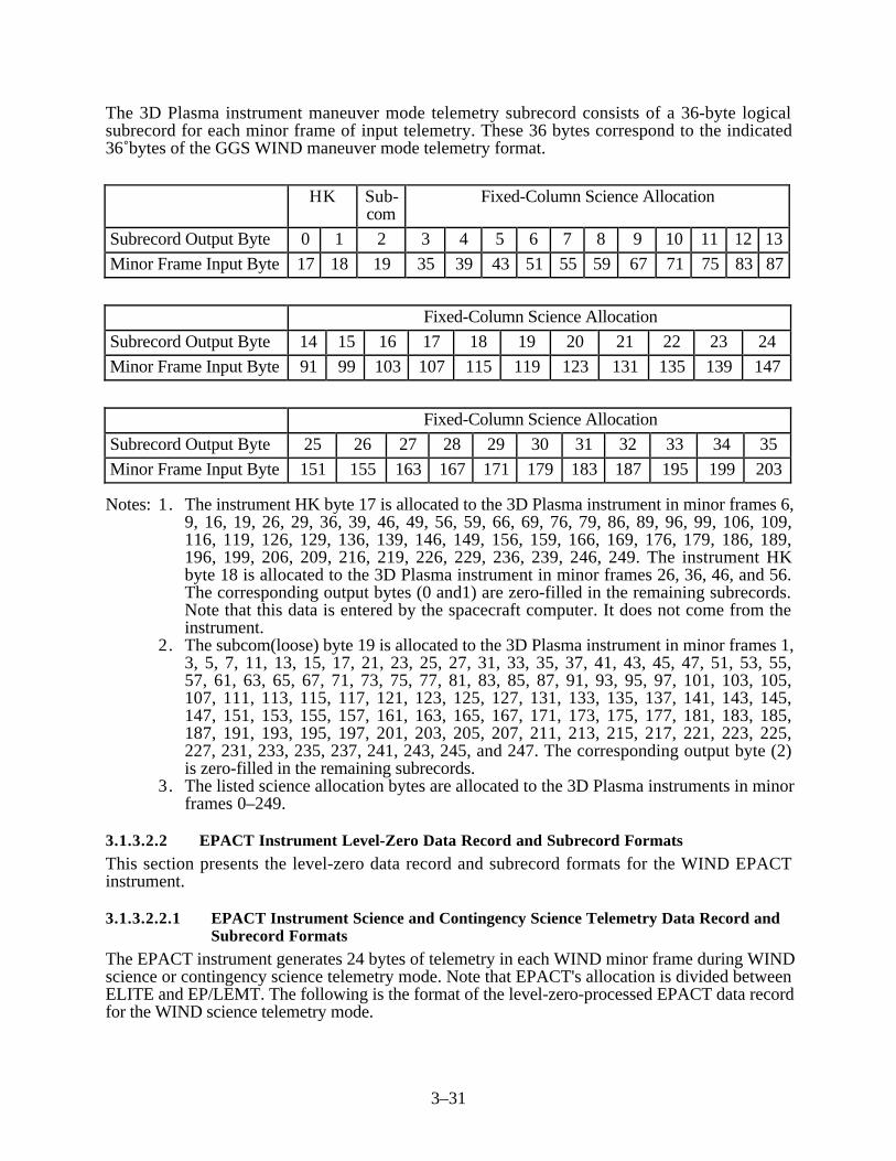
3–31
The 3D Plasma instrument maneuver mode telemetry subrecord consists of a 36-byte logicalsubrecord for each minor frame of input telemetry. These 36 bytes correspond to the indicated36 bytes of the GGS WIND maneuver mode telemetry format.
HK Sub-com
Fixed-Column Science Allocation
Subrecord Output Byte 0 1 2 3 4 5 6 7 8 9 10 11 12 13
Minor Frame Input Byte 17 18 19 35 39 43 51 55 59 67 71 75 83 87
Fixed-Column Science Allocation
Subrecord Output Byte 14 15 16 17 18 19 20 21 22 23 24
Minor Frame Input Byte 91 99 103 107 115 119 123 131 135 139 147
Fixed-Column Science Allocation
Subrecord Output Byte 25 26 27 28 29 30 31 32 33 34 35
Minor Frame Input Byte 151 155 163 167 171 179 183 187 195 199 203
Notes: 1. The instrument HK byte 17 is allocated to the 3D Plasma instrument in minor frames 6,9, 16, 19, 26, 29, 36, 39, 46, 49, 56, 59, 66, 69, 76, 79, 86, 89, 96, 99, 106, 109,116, 119, 126, 129, 136, 139, 146, 149, 156, 159, 166, 169, 176, 179, 186, 189,196, 199, 206, 209, 216, 219, 226, 229, 236, 239, 246, 249. The instrument HKbyte 18 is allocated to the 3D Plasma instrument in minor frames 26, 36, 46, and 56.The corresponding output bytes (0 and1) are zero-filled in the remaining subrecords.Note that this data is entered by the spacecraft computer. It does not come from theinstrument.
2. The subcom(loose) byte 19 is allocated to the 3D Plasma instrument in minor frames 1,3, 5, 7, 11, 13, 15, 17, 21, 23, 25, 27, 31, 33, 35, 37, 41, 43, 45, 47, 51, 53, 55,57, 61, 63, 65, 67, 71, 73, 75, 77, 81, 83, 85, 87, 91, 93, 95, 97, 101, 103, 105,107, 111, 113, 115, 117, 121, 123, 125, 127, 131, 133, 135, 137, 141, 143, 145,147, 151, 153, 155, 157, 161, 163, 165, 167, 171, 173, 175, 177, 181, 183, 185,187, 191, 193, 195, 197, 201, 203, 205, 207, 211, 213, 215, 217, 221, 223, 225,227, 231, 233, 235, 237, 241, 243, 245, and 247. The corresponding output byte (2)is zero-filled in the remaining subrecords.
3. The listed science allocation bytes are allocated to the 3D Plasma instruments in minorframes 0–249.
3.1.3.2.2 EPACT Instrument Level-Zero Data Record and Subrecord Formats
This section presents the level-zero data record and subrecord formats for the WIND EPACTinstrument.
3.1.3.2.2.1 EPACT Instrument Science and Contingency Science Telemetry Data Record andSubrecord Formats
The EPACT instrument generates 24 bytes of telemetry in each WIND minor frame during WINDscience or contingency science telemetry mode. Note that EPACT's allocation is divided betweenELITE and EP/LEMT. The following is the format of the level-zero-processed EPACT data recordfor the WIND science telemetry mode.

3–32
Item Description Length(bytes)
Record(bytes)
1 Data record header 300 0–299
2 Subrecord 1 containing EPACT level-zero data from WINDminor frame 0
24 300–323
3 Subrecord 2 containing EPACT level-zero data from WINDminor frame 1
24 324–347
4–250 Subrecord 3–249 containing EPACT level-zero data fromWIND minor frames 2–248
5,928 348–6275
251 Subrecord 250 containing EPACT level-zero data fromWIND minor frame 249
24 6276–6299
Total record length: 6300 bytes (1575 words)
The EPACT instrument science or contingency science telemetry format consists of a 24-bytelogical subrecord for each minor frame of input telemetry. These 24 bytes, which are split betweenELITE and EP/LEMT, correspond to the indicated 24 minor frame bytes of the GGS WINDspacecraft telemetry format.
HK EPACT
EP/LEMT
ELITE Subcom EP/LEMT Fixed-Column Science Allocation
SubrecordOutput Byte
0 1 2 3 4 5 6 7 8 9 10 11
Minor FrameInput Byte
17 18 20 182 186 190 194 196 198 201 205 209
EPACT Fixed-Column Science Allocation
Subrecord Output Byte 12 13 14 15 16 17 18 19 20 21 22 23
Minor Frame Input Byte 211 213 215 217 219 221 223 225 227 229 231 233
Notes: 1. The instrument HK byte 17 is allocated to the EPACT EP/LEMT instrument in minorframes 2, 12, 22, 32, 42, 52, 62, 72, 82, 92, 102, 112, 122, 132, 142, 152, 162,172, 182, 192, 202, 212, 222, 232, and 242. Byte 18 is allocated to the EPACTELITE instrument in minor frames 2, 6, 12, 16, 22, 32, 42, 52, 62, 72, 82, 92, 102,112, 122, 126, 132, 136, 142, 146, 152, 156, 162, 166, 172, 176, 182, 186, 192,196, 202, 206, 212, 216, 222, 226, 232, 236, 242, and 246. The correspondingoutput bytes (0 and 1) are zero-filled in the remaining subrecords.
2. The subcom(loose) byte 20 is allocated to the EPACT instrument in minor frames 1, 3, 5,7, 9, 11, 13, 15, 17, 19, 21, 23, 25, 27, 29, 31, 33, 35, 37, 39, 41, 43, 45, 47, 49, 51, 53, 55,57, 59, 61, 63, 65, 67, 69, 71, 73, 75, 77, 79, 81, 83, 85, 87, 89, 91, 93, 95, 97, 99, 100,101, 103, 105, 107, 109, 111, 113, 115, 117, 119, 120, 121, 123, 125, 127, 129, 131, 133,135, 137, 139, 140, 141, 143, 145, 147, 149, 151, 153, 155, 157, 159, 160, 161, 163, 165,167, 169, 170, 171, 173, 175, 177, 179, 180, 181, 183, 185, 187, 189, 190, 191, 193, 195,

3–33
197, 199, 200, 201, 203, 205, 207, 209, 210, 211, 213, 215, 217, 219, 220, 221, 223, 225,227, 229, 230, 231, 233, 235, 237, 239, 240, 241, 243, 245, 247, and 249. Thecorresponding output bytes (2 and 3) are zero-filled in the remaining subrecords.
3. The listed science allocation bytes are allocated to the EPACT instruments in minorframes 0–249.
3.1.3.2.2.2 EPACT Instrument Maneuver Mode Data Record and Subrecord Formats
The EPACT instrument generates 23 bytes of telemetry in each WIND minor frame during WINDmaneuver mode. The following is the format of the level-zero-processed EPACT data record forthe WIND maneuver mode.
Item Description Length(bytes)
Record(bytes)
1 Data record header 300 0–299
2 Subrecord 1 containing EPACT level-zero data from WINDminor frame 0
23 300–322
3 Subrecord 2 containing EPACT level-zero data from WINDminor frame 1
23 323–345
4–250 Subrecord 3–249 containing EPACT level-zero data fromWIND minor frames 2–248
5681 346–6026
251 Subrecord 250 containing EPACT level-zero data fromWIND minor frame 249
23 6027–6049
252 Zero (null) fill bytes to pad out to 4-byte word boundary 2 6050–6051
Total record length: 6052 bytes (1513 words)
The EPACT instrument maneuver mode telemetry subrecord consists of a 23-byte logicalsubrecord for each minor frame of telemetry. These 23 bytes, which are split between ELITE andLEMT, correspond to the indicated 23 bytes of the GGS WIND maneuver mode telemetry format.
HK Subcom
EP/LEMT
ELITE EP/LEMT/EPACT
EP/LEMT Fixed-Column Science Allocation
Subrecord OutputByte
0 1 2 3 4 5 6 7 8 9 10 11
Minor FrameInput Byte
17 18 20 182 186 190 194 196 198 201 205 209
EPACT Fixed-Column Science Allocation
Subrecord Output Byte 12 13 14 15 16 17 18 19 20 21 22
Minor Frame Input Byte 211 213 215 217 219 221 225 227 229 231 233

3–34
Notes: 1. The instrument HK byte 17 is allocated to the EP/LEMT instrument in minor frames 2,12, 22, 32, 42, 52, 62, 72, 82, 92, 102, 112, 122, 132, 142, 152, 162, 172, 182,192, 202, 212, 222, 232, and 242. HK byte 18 is allocated to the ELITE instrument inthe same minor frames and minor frames 6, 16, 126, 136, 146, 156, 166, 176, 186,196, 206, 216, 226, 236, 242, and 246. The corresponding output bytes (0 and 1) arezero-filled in the remaining subrecords.
2. The subcom(loose) byte 20 is allocated to the EPACT instrument in minor frames 1, 3,5, 7, 9, 11, 13, 15, 17, 19, 21, 23, 25, 27, 29, 31, 33, 35, 37, 39, 41, 43, 45, 47,49, 51, 53, 55, 57, 59, 61, 63, 65, 67, 69, 71, 73, 75, 77, 79, 81, 83, 85, 87, 89,91, 93, 95, 97, 99, 100, 101, 103, 105, 107, 109, 111, 113, 115, 117, 119, 120,121, 123, 125, 127, 129, 131, 133, 135, 137, 139, 140, 141, 143, 145, 147, 149,151, 153, 155, 157, 159, 160, 161, 163, 165, 167, 169, 170, 171, 173, 175, 177,179, 180, 181, 183, 185, 187, 189, 190, 191, 193, 195, 197, 199, 200, 201, 203,205, 207, 209, 210, 211, 213, 215, 217, 219, 220, 221, 223, 225, 227, 229, 230,231, 233, 235, 237, 239, 240, 241, 243, 245, 247, and 249. The correspondingoutput bytes (2 and 3) are zero-filled in the remaining subrecords.
3. The listed science allocation bytes are allocated to the EPACT instruments in minorframes 0–249.
3.1.3.2.3 KONUS Instrument Level-Zero Data Record and Subrecord Formats
This section presents the level-zero data record and subrecord formats for the WIND KONUSinstrument.
3.1.3.2.3.1 KONUS Instrument Science and Contingency Science Telemetry Data Record andSubrecord Formats
The KONUS instrument generates 6 bytes of telemetry in each WIND minor frame during WINDscience or contingency science telemetry mode. The following is the format of the level-zero-processed KONUS data record for the WIND science telemetry mode.
Item Description Length(bytes)
Record(bytes)
1 Data record header 300 0–299
2 Subrecord 1 containing KONUS level-zero data fromWIND minor frame 0
6 300–305
3 Subrecord 2 containing KONUS level-zero data fromWIND minor frame 1
6 306–311
4–250 Subrecord 3–249 containing KONUS level-zero data fromWIND minor frames 2–248
1482 312–1793
251 Subrecord 250 containing KONUS level-zero data fromWIND minor frame 249
6 1794–1799
252 Zero (null) fill bytes to pad out to minimum record length 992 1800–2791
Total record length: 2792 bytes (698 words)

3–35
The KONUS instrument science or contingency science telemetry format consists of a 6-bytelogical subrecord for each minor frame of input telemetry. These 6 bytes correspond to theindicated 6 minor frame bytes of the GGS WIND space craft telemetry format.
HK Subcom Fixed-Column ScienceAllocation
Subrecord Output Byte 0 1 2 3 4 5
Minor Frame Input Byte 17 18 19 20 193 197
Notes: 1. The instrument HK bytes 17 and 18 are allocated to the KONUS instrument in minorframes 5, 15, 25, 35, 45, 55, 65, 75, 85, 95, 105, 115, 125, 135, 145, 155, 165,175, 185, 195, 205, 215, 225, 235, and 245. The corresponding output bytes (0 and1) are zero-filled in the remaining subrecords.
2. The subcom (loose) bytes 19 and 20 are allocated to the KONUS instrument in minorframes 4, 6, 10, 14, 16, 24, 26, 30, 34, 36, 44, 46, 50, 54, 56, 64, 66, 70, 74, 76,84, 86, 90, 94, 96, 104, 106, 110, 114, 116, 124, 126, 130, 134, 136, 144, 146,150, 154, 156, 164, 166, 174, 176, 184, 186, 194, 196, 204, 206, 214, 216, 224,226, 234, 236, 244, and 246. The subcom byte 19 is also allocated to the KONUSinstrument in minor frames 100, 120, 140, 160, 170, 180, 190, 200, 210, 220, 230,and 240. The corresponding output bytes (2 and 3) are zero-filled in the remainingsubrecords.
3. The listed science allocation bytes are allocated to the KONUS instrument in minorframes 0–249.
3.1.3.2.3.2 KONUS Maneuver Mode Data Record and Subrecord Formats
The KONUS instrument generates 6 bytes of telemetry in each WIND minor frame during WINDmaneuver mode. The following is the format of the level-zero-processed KONUS data record forthe WIND maneuver mode.
Item Description Length(bytes)
Record(bytes)
1 Data record header 300 0–299
2 Subrecord 1 containing KONUS level-zero data fromWIND minor frame 0
6 300–305
3 Subrecord 2 containing KONUS level-zero data fromWIND minor frame 1
6 306–311
4–250 Subrecord 3–249 containing KONUS level-zero data fromWIND minor frames 2–248
1482 312–1793
251 Subrecord 250 containing KONUS level-zero data fromWIND minor frame 249
6 1794–1799
252 Zero (null) fill bytes to pad out to minimum record length 992 1800–2791
Total record length: 2792 bytes (698 words)

3–36
The KONUS instrument maneuver mode telemetry subrecord consists of a 6-byte logicalsubrecord for each minor frame of telemetry. These 6 bytes correspond to the indicated 6 bytes ofthe GGS WIND maneuver mode telemetry format.
HK SubcomFixed-Column Science
Allocation
Subrecord Output Byte 0 1 2 3 4 5
Minor Frame Input Byte 17 18 19 20 193 197
Notes: 1. The instrument HK bytes 17 and 18 are allocated to the KONUS instrument in minorframes 5, 15, 25, 35, 45, 55, 65, 75, 85, 95, 105, 115, 125, 135, 145, 155, 165,175, 185, 195, 205, 215, 225, 235, and 245. The corresponding output bytes (0 and1)are zero-filled in the remaining subrecords.
2. The subcom (loose) bytes 19 and 20 are allocated to the KONUS instrument in minorframes 4, 6, 10, 14, 16, 24, 26, 30, 34, 36, 44, 46, 50, 54, 56, 64, 66, 70, 74, 76,84, 86, 90, 94, 96, 104, 106, 110, 114, 116, 124, 126, 130, 134, 136, 144, 146,150, 154, 156, 164, 166, 174, 176, 184, 186, 194, 196, 204, 206, 214, 216, 224,226, 234, 236, 244, and 246. The subcom byte 19 is also allocated to the KONUSinstrument in minor frames 100, 120, 140, 160, 170, 180, 190, 200, 210, 220, 230,and 240. The corresponding output bytes (2 and 3) are zero-filled in the remainingsubrecords.
3. The listed science allocation bytes are allocated to the KONUS instrument in minorframes 0–249.
3.1.3.2.4 MFI Instrument Level-Zero Data Record and Subrecord Formats
This section presents the level-zero data record and subrecord formats for the WIND MFIinstrument.
3.1.3.2.4.1 MFI Instrument Science and Contingency Science Telemetry Data Record andSubrecord Formats
The MFI instrument generates 25 bytes of telemetry in each WIND minor frame during WINDscience or contingency science telemetry mode. The following is the format of the level-zero-processed MFI data record for the WIND science telemetry mode.
Item Description Length(bytes)
Record(bytes)
1 Data record header 300 0–299
2 Subrecord 1 containing MFI level-zero data from WINDminor frame 0
25 300–324
3 Subrecord 2 containing MFI level-zero data from WINDminor frame 1
25 325–349
4–250 Subrecord 3–249 containing MFI level-zero data fromWIND minor frames 2–248
6175 350–6524
251 Subrecord 250 containing MFI level-zero data from WINDminor frame 249
25 6525–6549

3–37
Item Description Length(bytes)
Record(bytes)
252 Zero (null) fill bytes to pad out to 4-byte word boundary 2 6550–6551
Total record length: 6552 bytes (1638 words)
The MFI instrument science or contingency science telemetry format consists of a 25-byte logicalsubrecord for each minor frame of input telemetry. These 25 bytes correspond to the indicated25 minor frame bytes of the GGS WIND spacecraft telemetry format.
HK Subcom Fixed-Column Science Allocation
Subrecord Output Byte 0 1 2 3 4 5 6 7 8 9 10
Minor Frame Input Byte 17 18 20 234 235 236 237 238 239 240 241
Fixed-Column Science Allocation
Subrecord Output Byte 11 12 13 14 15 16 17 18 19 20 21
Minor Frame Input Byte 242 243 244 245 246 247 248 249 250 251 252
Fixed-Column Science Allocation
Subrecord Output Byte 22 23 24
Minor Frame Input Byte 253 254 255
Notes: 1. The instrument HK bytes 17 and 18 are allocated to the MFI instrument in minorframes 0, 10, 20, 30, 40, 50, 60, 70, 80, 90, 100, 110, 120, 130, 140, 150, 160,170, 180, 190, 200, 210, 220, 230, and 240. The corresponding output bytes (0 and1) are zero-filled in the remaining subrecords.
2. The subcom(loose) byte 20 is allocated to the MFI instrument in minor frames 2, 12,22, 32, 42, 52, 62, 72, 82, 92, 102, 112, 122, 132, 142, 152, 162, 172, 182, 192,202, 212, 222, 232, and 242. The corresponding output byte (2) is zero-filled in theremaining subrecords.
3.1.3.2.4.2 MFI Instrument Maneuver Mode Data Record and Subrecord Format
The MFI instrument generates 23 bytes of telemetry in each WIND minor frame during WINDmaneuver mode. The following is the format of the level-zero-processed MFI data record for theWIND maneuver mode.
Item Description Length(bytes)
Record(bytes)
1 Data record header 300 0–299
2 Subrecord 1 containing MFI level-zero data from WINDminor frame 0
23 300–322

3–38
Item Description Length(bytes)
Record(bytes)
3 Subrecord 2 containing MFI level-zero data from WINDminor frame 1
23 323–345
4–250 Subrecord 3–249 containing MFI level-zero data fromWIND minor frames 2–248
5681 346–6026
251 Subrecord 250 containing MFI level-zero data from WINDminor frame 249
23 6027–6049
252 Zero (null) fill bytes to pad out to 4-byte word boundary 2 6050–6051
Total record length: 5800 bytes (1450 words)
The MFI instrument maneuver mode telemetry subrecord consists of a 23-byte logical subrecordfor each minor frame of telemetry. These 23 bytes correspond to the indicated 23 bytes of the GGSWIND maneuver mode telemetry format.
HK Sub-com
Fixed-Column Science Allocation
Subrecord OutputByte
0 1 2 3 4 5 6 7 8 9 10 11 12 13
Minor Frame InputByte
17 18 20 234 235 236 237 238 240 241 242 243 244 245
Fixed-Column Science Allocation
Subrecord Output Byte 14 15 16 17 18 19 20 21 22
Minor Frame Input Byte 246 247 248 249 250 251 252 253 254
Notes: 1. The instrument HK bytes 17 and 18 are allocated to the MFI instrument in minorframes 0, 10, 20, 30, 40, 50, 60, 70, 80, 90, 100, 110, 120, 130, 140, 150, 160,170, 180, 190, 200, 210, 220, 230, and 240. The corresponding output bytes (0 and1)are zero-filled in the remaining subrecords.
2. The subcom(loose) byte 20 is allocated to the MFI instrument in minor frames 2, 12,22, 32, 42, 52, 62, 72, 82, 92, 102, 112, 122, 132, 142, 152, 162, 172, 182, 192,202, 212, 222, 232, and 242. The corresponding output byte (2) is zero-filled in theremaining subrecords.
3. The listed science allocation bytes are allocated to the MFI instrument in minor frames0–249.
3.1.3.2.5 SMS Instrument Level-Zero Data Record and Subrecord Formats
This section presents the level-zero data record and subrecord formats for the WIND SMSinstrument.

3–39
3.1.3.2.5.1 SMS Instrument Science and Contingency Science Telemetry Data Record andSubrecord Formats
The SMS instrument generates 42 bytes of telemetry in each WIND minor frame during WINDscience or contingency science telemetry mode. The following is the format of the level-zero-processed SMS data record for the WIND science telemetry mode.
Item Description Length(bytes)
Record(bytes)
1 Data record header 300 0–299
2 Subrecord 1 containing SMS level-zero data from WINDminor frame 0
42 300–341
3 Subrecord 2 containing SMS level-zero data from WINDminor frame 1
42 342–383
4–250 Subrecord 3–249 containing SMS level-zero data fromWIND minor frames 2–248
10,374 384–10,757
251 Subrecord 250 containing SMS level-zero data fromWIND minor frame 249
42 10,758–10,799
Total record length: 10,800 bytes (2700 words)
The SMS instrument science or contingency science telemetry format consists of a 42-byte logicalsubrecord for each minor frame of input telemetry. These 42 bytes correspond to the indicated42 minor frame bytes of the GGS WIND spacecraft telemetry format.
HK Fixed-Column Science Allocation
Subrecord Output Byte 0 1 2 3 4 5 6 7 8 9 10 11
Minor Frame Input Byte 17 18 22 26 30 34 38 42 46 50 54 58
Fixed-Column Science Allocation
Subrecord Output Byte 12 13 14 15 16 17 18 19 20 21 22 23
Minor Frame Input Byte 62 66 70 74 78 82 86 90 94 98 102 106
Fixed-Column Science Allocation
Subrecord Output Byte 24 25 26 27 28 29 30 31 32 33 34 35
Minor Frame Input Byte 110 114 118 122 126 130 134 138 142 146 150 154
Fixed-Column Science Allocation
Subrecord Output Byte 36 37 38 39 40 41
Minor Frame Input Byte 158 162 166 170 174 178

3–40
Notes: 1. The HK byte 17 is allocated to SMS in minor frames 1, 11, 21, 31, 41, 51, 61, 71, 81,91, 101, 111, 121, 131, 141, 151, 161, 171, 181, 191, 201, 211, 221, 231, and 241.The instrument HK byte 18 is allocated to the SMS in minor frames 3, 7, 13, 17, 23,27, 33, 37, 43, 47, 53, 57, 63, 67, 73, 77, 83, 87, 93, 97, 103, 107, 113, 117, 123,127, 133, 137, 143, 147, 153, 157, 163, 167, 173, 177, 183, 187, 193, 197, 203,207, 213, 217, 223, 227, 233, 237, 243, and 247. The corresponding output bytes (0and 1) are zero-filled in the remaining subrecords.
2. The listed science allocation bytes are allocated to the SMS instrument in minor frames0–249.
3.1.3.2.5.2 SMS Instrument Maneuver Mode Data Record and Subrecord Formats
The SMS instrument generates 35 bytes of telemetry in the WIND minor frame during WINDmaneuver mode. The following is the format of the level-zero-processed SMS data record for theWIND maneuver mode.
Item Description Length(bytes)
Record(bytes)
1 Data record header 300 0–299
2 Subrecord 1 containing SMS level-zero data from WINDminor frame 0
35 300–334
3 Subrecord 2 containing SMS level-zero data from WINDminor frame 1
35 335–369
4–250 Subrecord 3–249 containing SMS level-zero data fromWIND minor frames 2–248
8645 370–9014
251 Subrecord 250 containing SMS level-zero data fromWIND minor frame 249
35 9015–9049
252 Zero (null) fill bytes to pad out to 4-byte word boundary 2 9050–9051
Total record length: 9052 bytes (2263 words)
The SMS instrument maneuver mode telemetry subrecord consists of a 35-byte logical subrecordfor each minor frame of telemetry. These 35 bytes correspond to the indicated 35 bytes of the GGSWIND maneuver mode telemetry format.
HK Fixed-Column Science Allocation
Subrecord Output Byte 0 1 2 3 4 5 6 7 8 9 10 11 12
Minor Frame Input Byte 17 18 34 38 42 46 50 54 58 62 66 70 74
Fixed-Column Science Allocation
Subrecord Output Byte 13 14 15 16 17 18 19 20 21 22 23
Minor Frame Input Byte 78 82 86 90 94 98 102 106 110 114 118

3–41
Fixed-Column Science Allocation
Subrecord Output Byte 24 25 26 27 28 29 30 31 32 33 34
Minor Frame Input Byte 122 126 130 134 138 142 146 150 154 158 162
Notes: 1. The HK byte 17 is allocated to SMS in minor frames 1, 11, 21, 31, 41, 51, 61, 71, 81,91, 101, 111, 121, 131, 141, 151, 161, 171, 181, 191, 201, 211, 221, 231, and 241.The instrument HK byte 18 is allocated to the SMS in minor frames 3, 7, 13, 17, 23,27, 33, 37, 43, 47, 53, 57, 63, 67, 73, 77, 83, 87, 93, 97, 103, 107, 113, 117, 123,127, 133, 137, 143, 147, 153, 157, 163, 167, 173, 177, 183, 187, 193, 197, 203,207, 213, 217, 223, 227, 233, 237, 243, and 247. The corresponding output bytes (0and 1) are zero-filled in the remaining subrecords.
2. The tested science allocation bytes are allocated to the SMS instrument in minor frames0–249.
3.1.3.2.6 SWE Instrument Level-Zero Data Record and Subrecord Formats
This section presents the level-zero data record and subrecord formats for the WIND SWEinstrument.
3.1.3.2.6.1 SWE Instrument Science and Contingency Science Telemetry Data Record andSubrecord Formats
The SWE instrument generates 45 bytes of telemetry in each WIND minor frame during WINDscience or contingency science telemetry mode. The following is the format of the level-zero-processed SWE data record for the WIND science telemetry mode.
Item Description Length(bytes)
Record(bytes)
1 Data record header 300 0–299
2 Subrecord 1 containing SWE level-zero data from WINDminor frame 0
45 300–344
3 Subrecord 2 containing SWE level-zero data from WINDminor frame 1
45 345–389
4–250 Subrecord 3–249 containing SWE level-zero data fromWIND minor frames 2–248
11,115 390–11,504
251 Subrecord 250 containing SWE level-zero data fromWIND minor frame 249
45 11,505–11,549
252 Zero (null) fill bytes to pad record out to 4-byte wordboundary
2 11,550–11,551
Total record length: 11,552 bytes (2888 words)
The SWE instrument science or contingency science telemetry format consists of a 45-byte logicalsubrecord for each minor frame of input telemetry. These 45 bytes correspond to the indicated 45minor frame bytes of the GGS WIND spacecraft telemetry format.

3–42
HK Subcom Fixed-Column Science Allocation
Subrecord Output Byte 0 1 2 3 4 5 6 7 8 9 10 11
Minor Frame Input Byte 17 19 21 25 29 33 37 41 45 49 53 57
Fixed-Column Science Allocation
Subrecord Output Byte 12 13 14 15 16 17 18 19 20 21 22 23
Minor Frame Input Byte 61 65 69 73 77 81 85 89 93 97 101 105
Fixed-Column Science Allocation
Subrecord Output Byte 24 25 26 27 28 29 30 31 32 33 34 35
Minor Frame Input Byte 109 113 117 121 125 129 133 137 141 145 149 153
Fixed-Column Science Allocation
Subrecord Output Byte 36 37 38 39 40 41 42 43 44
Minor Frame Input Byte 157 161 165 169 173 177 181 185 189
Notes: 1. The instrument HK byte 17 is allocated to the SWE instrument in minor frames 3, 7,13, 17, 23, 27, 33, 37, 43, 47, 53, 57, 63, 67, 73, 77, 83, 87, 93, 97, 103, 107, 113,117, 123, 127, 133, 137, 143, 147, 153, 157, 163, 167, 173, 177, 183, 187, 193,197, 203, 207, 213, 217, 223, 227, 233, 237, 243, and 247. The correspondingoutput byte (0) is zero-filled in the remaining subrecords.
2. The subcom (loose) byte 19 is allocated to the SWE instrument in minor frames 2, 9, 12,19, 22, 29, 32, 39, 42, 49, 52, 59, 62, 69, 72, 79, 82, 89, 92, 99, 102, 109, 112, 119, 122,129, 132, 139, 142, 149, 152, 159, 162, 169, 172, 179, 182, 189, 192, 199, 202, 209, 212,219, 222, 229, 232, 239, 242, and 249. The corresponding output byte (1) is zero-filledin the remaining subrecords.
3. The listed science allocation bytes to the SWE instrument in minor frames 0–249.
3.1.3.2.6.2 SWE Instrument Maneuver Mode Record and Subrecord Formats
The SWE instrument generates 2 bytes of telemetry in each WIND minor frame during WINDmaneuver mode. The following is the format of the level-zero-processed SWE data record for theWIND maneuver mode.
Item Description Length(bytes)
Record(bytes)
1 Data record header 300 0–299
2 Subrecord 1 containing SWE level-zero data from WINDminor frame 0
2 300–301
3 Subrecord 2 containing SWE level-zero data from WINDminor frame 1
2 302–303

3–43
Item Description Length(bytes)
Record(bytes)
4–250 Subrecord 3–249 containing SWE level-zero data fromWIND minor frames 2–248
494 304–797
251 Subrecord 250 containing SWE level-zero data from WINDminor frame 249
2 798–799
252 Zero (null) fill bytes to pad out to minimum record length 1992 800–2791
Total record length: 2792 bytes (698 words)
The SWE instrument maneuver mode telemetry subrecord consists of a 2-byte logical subrecordfor each minor frame of telemetry. These 2 bytes correspond to the indicated 2 bytes of the GGSWIND maneuver mode telemetry format.
HK Subcom
Subrecord Output Byte 0 1
Minor Frame Input Byte 17 19
Notes: 1. The instrument HK byte 17 is allocated to the SWE instrument in minor frames 3, 7,13, 17, 23, 27, 33, 37, 43, 47, 53, 57, 63, 67, 73, 77, 83, 87, 93, 97, 103, 107, 113,117, 123, 127, 133, 137, 143, 147, 153, 157, 163, 167, 173, 177, 183, 187, 193,197, 203, 207, 213, 217, 223, 227, 233, 237, 243, and 247. The correspondingoutput byte (0) is zero-filled in the remaining subrecords.
2. The subcom (loose) byte 19 is allocated to the SWE instrument in minor frames 2, 9,12, 19, 22, 29, 32, 39, 42, 49, 52, 59, 62, 69, 72, 79, 82, 89, 92, 99, 102, 109, 112,119, 122, 129, 132, 139, 142, 149, 152, 159, 162, 169, 172, 179, 182, 189, 192,199, 202, 209, 212, 219, 222, 229, 232, 239, 242, and 249. The correspondingoutput byte 1 is zero-filled in the remaining subrecords.
3. No fixed column science allocation bytes are allocated to the SWE instrument.
3.1.3.2.7 TGRS Instrument Level-Zero Data Record and Subrecord Formats
This section presents the level-zero data record and subrecord formats for the WIND TGRSinstrument.
3.1.3.2.7.1 TGRS Instrument Science and Contingency Science Telemetry Data Record andSubrecord Formats
The TGRS instrument generates 21 bytes of telemetry in each WIND minor frame during WINDscience or contingency science telemetry mode. The following is the format of the level-zero-processed TGRS data record for the WIND science telemetry mode.

3–44
Item Description Length(bytes)
Record(bytes)
1 Data record header 300 0–299
2 Subrecord 1 containing TGRS level-zero data from WINDminor frame 0
21 300–320
3 Subrecord 2 containing TGRS level-zero data from WINDminor frame 1
21 321–341
4–250 Subrecord 3–249 containing TGRS level-zero data fromWIND minor frames 2–248
5187 342–5528
251 Subrecord 250 containing TGRS level-zero data fromWIND minor frame 249
21 5529–5549
252 Zero (null) fill bytes to pad out to 4-byte word boundary 2 5550–5551
Total record length: 5552 bytes (1388 words)
The TGRS instrument science or contingency science telemetry format consists of a 21-byte logicalsubrecord for each minor frame of input telemetry. These 21 bytes correspond to the indicated 21minor frame bytes of the GGS WIND spacecraft telemetry format.
HK Subcom Fixed-Column Science Allocation
Subrecord Output Byte 0 1 2 3 4 5 6 7 8 9 10
Minor Frame Input Byte 17 18 19 20 200 202 204 206 208 210 212
Fixed-Column Science Allocation
Subrecord Output Byte 11 12 13 14 15 16 17 18 19 20
Minor Frame Input Byte 214 216 218 220 222 224 226 228 230 232
Notes: 1. The instrument HK bytes 17 and 18 are allocated to the TGRS instrument in minorframes 8, 18, 28, 38, 48, 58, 68, 78, 88, 98, 108, 118, 128, 138, 148, 158, 168,178, 188, 198, 208, 218, 228, 238, and 248. The corresponding output bytes (0 and1) are zero-filled in the remaining records.
2. The subcom (loose) bytes 19 and 20 are allocated to the TGRS instrument in minorframes 0, 8, 18, 20, 28, 38, 40, 48, 58, 60, 68, 78, 80, 88, 98, 108, 118, 128, 138,148, 158, 168, 178, 188, 198, 208, 218, 228, 238, and 248. The correspondingoutput bytes (2 and 3) are zero-filled in the remaining subrecords.
3. The listed science allocation bytes are allocated to the TGRS instrument in minor frames0–249.
3.1.3.2.7.2 TGRS Instrument Maneuver Mode Data Record and Subrecord Formats
The TGRS instrument generates 21 bytes of telemetry in each WIND minor frame during WINDmaneuver mode. The following is the format of the level-zero-processed TGRS data record for theWIND maneuver mode.

3–45
Item Description Length(bytes)
Record(bytes)
1 Data record header 300 0–299
2 Subrecord 1 containing TGRS level-zero data from WINDminor frame 0
21 300–320
3 Subrecord 2 containing TGRS level-zero data from WINDminor frame 1
21 321–341
4–250 Subrecord 3–249 containing TGRS level-zero data fromWIND minor frames 2–248
5187 342–5528
251 Subrecord 250 containing TGRS level-zero data fromWIND minor frame 249
21 5529–5549
252 Zero (null) fill bytes to pad out to 4-byte word boundary 2 5550–5551
Total record length: 5552 bytes (1388 words)
The TGRS instrument maneuver mode telemetry subrecord consists of a 21-byte logical subrecordfor each minor frame of telemetry. These 21 bytes correspond to the indicated 21 bytes of the GGSWIND maneuver mode telemetry format.
HK Sub-com
Fixed-Column Science Allocation
SubrecordOutput Byte
0 1 2 3 4 5 6 7 8 9 10 11 12 13 14
Minor FrameInput Byte
17 18 19 20 200 202 204 206 208 210 212 214 216 218 220
Fixed-Column Science Allocation
Subrecord Output Byte 15 16 17 18 19 20
Minor Frame Input Byte 222 224 226 228 230 232
Notes: 1. The instrument HK bytes 17 and 18 are allocated to the TGRS instrument in minorframes 8, 18, 28, 38, 48, 58, 68, 78, 88, 98, 108, 118, 128, 138, 148, 158, 168,178, 188, 198, 208, 218, 228, 238, and 248. The corresponding output bytes (0 and1) are zero-filled in the remaining subrecords.
2. The subcom (loose) bytes 19 and 20 are allocated to the TGRS instrument in minorframes 0, 8, 18, 20, 28, 38, 40, 48, 58, 60, 68, 78, 80, 88, 98, 108, 118, 128, 138,148, 158, 168, 178, 188, 198, 208, 218, 228, 238, and 248. The correspondingoutput bytes (2 and 3) are zero-filled in the remaining subrecords.
3. The listed science allocation bytes are allocated to the TGRS instrument in minor frames0–249.
3.1.3.2.8 WAVES Instrument Level-Zero Data Record and Subrecord Formats
This section presents the level-zero data record and subrecord formats for the WIND WAVESinstrument.

3–46
3.1.3.2.8.1 WAVES Instrument Science and Contingency Science Telemetry Data Record andSubrecord Formats
The WAVES instrument generates 45 bytes of telemetry in each WIND minor frame during WINDscience telemetry mode. The following is the format of the level-zero-processed WAVES datarecord for the WIND science telemetry mode.
Item Description Length(bytes)
Record(bytes)
1 Data record header 300 0–299
2 Subrecord 1 containing WAVES level-zero data fromWIND minor frame 0
45 300–344
3 Subrecord 2 containing WAVES level-zero data fromWIND minor frame 1
45 345–389
4–250 Subrecord 3–249 containing WAVES level-zero datafrom WIND minor frames 2–248
11,115 390–11,504
251 Subrecord 250 containing WAVES level-zero data fromWIND minor frame 249
45 11,505–11,549
252 Zero (null) fill bytes to pad out to 4-byte word boundary 2 11,550–11,551
Total record length: 11,552 bytes (2888 words)
The WAVES instrument science or contingency science telemetry format consists of a 45-bytelogical subrecord for each minor frame of input telemetry. These 45 bytes correspond to theindicated 45 minor frame bytes of the GGS WIND spacecraft telemetry format.
HK Fixed-Column Science Allocation
Subrecord Output Byte 0 1 2 3 4 5 6 7 8 9 10
Minor Frame Input Byte 17 18 24 28 32 36 40 44 48 52 56
Fixed-Column Science Allocation
Subrecord Output Byte 11 12 13 14 15 16 17 18 19 20 21 22
Minor Frame Input Byte 60 64 68 72 76 80 84 88 92 96 100 104
Fixed-Column Science Allocation
Subrecord Output Byte 23 24 25 26 27 28 29 30 31 32 33 34
Minor Frame Input Byte 108 112 116 120 124 128 132 136 140 144 148 152

3–47
Fixed-Column Science Allocation
Subrecord Output Byte 35 36 37 38 39 40 41 42 43 44
Minor Frame Input Byte 156 160 164 168 172 176 180 184 188 192
Notes: 1. The instrument HK bytes 17 and 18 are allocated to the WAVES instrument in minorframes 4, 14, 24, 34, 44, 54, 64, 74, 84, 94, 104, 114, 124, 134, 144, 154, 164,174, 184, 194, 204, 214, 224, 234, and 244. Byte 18 is also allocated to WAVES inminor frames 1, 9, 11, 19, 21, 29, 31, 39, 41, 49, 51, 59, 61, 66, 69, 71, 76, 79, 81,86, 89, 91, 96, 99, 101, 106, 109, 111, 116, 119, 121, 129, 131, 139, 141, 149,151, 159, 161, 169, 171, 179, 181, 189, 191, 199, 201, 209, 211, 219, 221, 229,231, 239, 241, and 249. The corresponding output bytes (0 and 1) are zero-filled in theremaining subrecords.
2. The listed science allocation bytes are allocated to the WAVES instrument in minorframes 0–249.
3.1.3.2.8.2 WAVES Instrument Maneuver Mode Data Record and Subrecord Formats
The WAVES instrument generates 61 bytes of telemetry in each WIND minor frame during WINDmaneuver mode. The following is the format of the level-zero-processed WAVES data record forthe WIND maneuver mode.
Item Description Length(bytes)
Record(bytes)
1 Data record header 300 0–299
2 Subrecord 1 containing WAVES level-zero data fromWIND minor frame 0
61 300–360
3 Subrecord 2 containing WAVES level-zero data fromWIND minor frame 1
61 361–421
4–250 Subrecord 3–249 containing WAVES level-zero datafrom WIND minor frames 2–248
15,067 422–15,488
251 Subrecord 250 containing WAVES level-zero data fromWIND minor frame 249
61 14,489–15,549
252 Zero (null) fill bytes to pad out to 4-byte word boundary 2 15,550–15,551
Total record length: 15,552 bytes (3888 words)
The WAVES instrument maneuver mode telemetry subrecord consists of a 61-byte logicalsubrecord for each minor frame of telemetry to the indicated 61 bytes of the GGS WIND maneuvermode telemetry format.
HK Fixed-Column Science Allocation
Subrecord Output Byte 0 1 2 3 4 5 6 7 8 9 10 11 12
Minor Frame Input Byte 17 18 32 33 36 37 40 41 44 45 48 49 52

3–48
Fixed-Column Science Allocation
Subrecord Output Byte 13 14 15 16 17 18 19 20 21 22 23 24 25
Minor Frame Input Byte 53 56 57 60 61 64 65 68 69 72 73 76 77
Fixed-Column Science Allocation
Subrecord Output Byte 26 27 28 29 30 31 32 33 34 35 36 37
Minor Frame Input Byte 80 81 84 85 88 89 92 93 96 97 100 101
Fixed-Column Science Allocation
Subrecord Output Byte 38 39 40 41 42 43 44 45 46 47 48 49
Minor Frame Input Byte 104 108 112 116 120 124 128 132 136 140 144 148
Fixed-Column Science Allocation
Subrecord Output Byte 50 51 52 53 54 55 56 57 58 59 60
Minor Frame Input Byte 152 156 160 164 168 172 176 180 184 188 192
Notes: 1. The instrument HK bytes 17 and 18 are allocated to the WAVES instrument in minorframes 4, 14, 24, 34, 44, 54, 64, 74, 84, 94, 104, 114, 124, 134, 144, 154, 164,174, 184, 194, 204, 214, 224, 234, and 244. The HK byte 18 also is allocated to theWAVES instrument in minor frames 1, 9, 11, 19, 21, 29, 31, 39, 41, 49, 51, 59, 61,66, 69, 71, 76, 79, 81, 86, 89, 91, 96, 99, 101, 106, 109, 111, 116, 119, 121, 129,131, 139, 141, 149, 151, 159, 161, 169, 171, 179, 181, 189, 191, 199, 201, 209,211, 219, 221, 229, 231, 239, 241, and 249. The corresponding output bytes (0 and1)are zero-filled in the remaining subrecords.
2. The listed science allocation bytes are allocated to the WAVES instrument in minorframes 0–249.
3.1.3.3 POLAR Spacecraft Level-Zero Data Record and Subrecord Formats
This section presents the level-zero data record and subrecord formats for each instrument onboardthe POLAR spacecraft.
Formats are provided for three POLAR spacecraft telemetry modes: science telemetry (usual),contingency science telemetry, and maneuver. The mode is indicated in the DRH. POLARcontingency science telemetry mode is used when a failure contingency occurs that preventseffective use of the spacecraft's despun platform. In this mode, the telemetry bytes that arenormally allocated to the instruments on the despun platform are reallocated among the remaininginstruments. Note that a switch to this mode is most probably a one-time shot without expectationof returning to the normal science telemetry mode. Refer to Section 3.1.3.2 for a description ofmaneuver mode.
NRT level-zero data is generated on the CDHF but not distributed to the DDF. The format of theNRT level-zero data is identical to the format of the production level-zero data originating from theGDCF. Because of the NRT system operation, the record size for each instrument's NRT level-zero data is set to the largest record size possible for the instrument. For example, if the productionCAMMICE level-zero data record size is 2,800 bytes during science and maneuver telemetry

3–49
modes and 4,552 bytes during contingency science telemetry mode, the record size for CAMMICENRT level-zero data is always 4,552 bytes (the larger of the two record sizes). In cases where theNRT record size for the current telemetry mode is less than the maximum, the remaining bytes inthe record are zero-filled.
Figure 3–4 depicts the high-level telemetry format for the POLAR spacecraft. The detailedtelemetry formats for the POLAR spacecraft are in Reference 9. Note that a major frame contains250 minor frames (numbered 0–249) of 256 bytes (numbered 0–255) each.
Note: The following subsections specify for each instrument onboard the POLAR spacecraft whichtelemetry bytes are allocated to the instrument. Identified fixed-column bytes are allocated to therespective instrument in every minor frame. Notes are used to indicate which minor frames containHK and subcom bytes for the instrument.
In contingency science mode for the POLAR mission, the telemetry allocated to the instruments onthe despun platform is reallocated to the remaining instruments in roughly the same proportion asinthe science mode. This mode is restricted in that only whole columns (fixed frame) and nosubcom (loose) bytes are allocated.
3.1.3.3.1 CAMMICE Instrument Level-Zero Data Record and Subrecord Formats
This section presents the level-zero data record and subrecord formats for the POLAR CAMMICEinstrument.
Instru-ment HK Subcom
0
1
2
•
Minor
Frames
Bytes
0 1 • • 11 12 13 14 • • 38 • • 255
•
249
Fixed Column
Fixed ColumnSubcom
15 16 17
Figure 3–4. POLAR Major Frame Telemetry Format

3–50
3.1.3.3.1.1 CAMMICE Instrument Science Telemetry Data Record and Subrecord Formats
The CAMMICE instrument generates 10 bytes of telemetry in each POLAR minor frame duringPOLAR Science telemetry mode. The following is the format of the level-zero-processedCAMMICE data record for the POLAR science telemetry mode.
Item Description Length(bytes)
Record(bytes)
1 Data record header 300 0–299
2 Subrecord 1 containing CAMMICE level-zero data fromPOLAR minor frame 0
10 300–309
3 Subrecord 2 containing CAMMICE level-zero data fromPOLAR minor frame 1
10 310–319
4–250 Subrecord 3–249 containing CAMMICE level-zero datafrom POLAR minor frames 2–248
2470 320–2789
251 Subrecord 250 containing CAMMICE level-zero data fromPOLAR minor frame 249
10 2790–2799
Total record length: 2800 bytes (700 words)
The CAMMICE instrument science telemetry subrecord format consists of a 10-byte logicalsubrecord for each minor frame of telemetry. These 10 bytes correspond to the indicated 10 minorframe bytes of the GGS POLAR spacecraft telemetry format.
HK Subcom Fixed-Column Science Allocation
HIT MICS MICS/HIT
HIT MICS HIT
Subrecord Output Byte 0 1 2 3 4 5 6 7 8 9
Minor Frame Input Byte 11 12 15 16 184 185 186 200 201 202
Notes: 1. The instrument HK byte 11 is allocated to the CAMMICE (HIT) instrument in minorframes 8, 56, 68, 80, 92, 116, 128, 140, 152, 164, 176, 188, 200, 212, 224, 236,and 248. The HK byte 12 is allocated to the CAMMICE (MICS) instrument in minorframes 8, 20, 32, 44, 56, 68, 80, 92, 104, 116, 128, 140, 152, 164, 176, 188, 200,212, 224, 236, and 248. The corresponding output bytes (0 and 1) are zero-filled in theremaining subrecords.
2. The subcom(loose) byte 15 is allocated to the CAMMICE MICS instrument in minorframes 0–60 and CAMMICE HIT instrument in minor frames 61–89. The subcom byte16 is allocated to CAMMICE HIT in minor frames 210–241. The corresponding outputbytes (2 and 3) are zero-filled in the remaining subrecords.
3. The listed science allocation data in bytes 184–186 and 200–202 will be allocated to theCAMMICE instrument in minor frames 0–249. Bytes 184–186 are allocated to MICSdata, and bytes 200–202 are allocated to HIT data.

3–51
3.1.3.3.1.2 CAMMICE Instrument Contingency Science Telemetry Data Record andSubrecord Formats
The CAMMICE instrument generates 17 bytes of telemetry in each POLAR minor frame duringPOLAR contingency mode. The following is the format of the level-zero-processed CAMMICEdata record for the POLAR contingency mode.
Item Description Length(bytes)
Record(bytes)
1 Data record header 300 0–299
2 Subrecord 1 containing CAMMICE level-zero data fromPOLAR minor frame 0
17 300–316
3 Subrecord 2 containing CAMMICE level-zero data fromPOLAR minor frame 1
17 317–333
4–250 Subrecord 3–249 containing CAMMICE level-zero datafrom POLAR minor frames 2–248
4199 334–4532
251 Subrecord 250 containing CAMMICE level-zero data fromPOLAR minor frame 249
17 4533–4549
252 Zero (null) Fill bytes to pad record out to the 4-byte wordboundary
2 4550–4551
Total record length: 4552 bytes (1138 words)
The CAMMICE instrument contingency science telemetry subrecord format consists of a 17-bytelogical subrecord is corresponding to the indicated 17 bytes of the GGS POLAR spacecraftcontingency science telemetry format.
HK Fixed-Column Science Allocation
HIT MICS MICS HIT
Subrecord Output Byte 0 1 2 3 4 5 6 7 8 9 10 11
Minor Frame Input Byte 11 12 25 26 27 45 46 47 65 66 67 85
Fixed-Column Science Allocation (HIT)
Subrecord Output Byte 12 13 14 15 16
Minor Frame Input Byte 86 87 105 106 107
Notes: 1. The instrument HK byte 11 is allocated to the CAMMICE (HIT) instrument in minorframes 8, 56, 68, 80, 92, 116, 128, 140, 152, 164, 176, 188, 200, 212, 224, 236,and 248. The instrument HK byte 12 is allocated to the CAMMICE (MICS) instrumentin minor frames 8, 20, 32, 44, 56, 68, 80, 92, 104, 116, 128, 140, 152, 164, 176,188, 200, 212, 224, 236, and 248.
2. The listed science allocation bytes are allocated to the CAMMICE instrument in minorframes 0–249.

3–52
3.1.3.3.1.3 CAMMICE Instrument Maneuver Mode Data Record and Subrecord Formats
The CAMMICE instrument generates 10 bytes of telemetry in each POLAR minor frame duringPOLAR maneuver mode. The following is the format of the level-zero-processed CAMMICE datarecord for the POLAR maneuver mode.
Item Description Length(bytes)
Record(bytes)
1 Data record header 300 0–299
2 Subrecord 1 containing CAMMICE level-zero data fromPOLAR minor frame 0
10 300–309
3 Subrecord 2 containing CAMMICE level-zero data fromPOLAR minor frame 1
10 310–319
4–250 Subrecord 3–249 containing CAMMICE level-zero datafrom POLAR minor frames 2–248
2470 320–2789
251 Subrecord 250 containing CAMMICE level-zero data fromPOLAR minor frame 249
10 2790–2799
Total record length: 2800 bytes (700 words)
The CAMMICE instrument maneuver mode telemetry subrecord consists of a 10-byte logicalsubrecord for each minor frame of telemetry to the indicated 10 bytes of the GGS POLARmaneuver mode telemetry format.
HK Subcom Fixed-Column Science Allocation
HIT MICS MICS/HIT
HIT MICS HIT
Subrecord Output Byte 0 1 2 3 4 5 6 7 8 9
Minor Frame Input Byte 11 12 15 16 184 185 186 200 201 202
Notes: 1. The instrument HK byte 11 is allocated to the CAMMICE (HIT) instrument in minorframes 8, 56, 68, 80, 92, 116, 128, 140, 152, 164, 176, 188, 200, 212, 224, 236,and 248. The HK byte 12 is allocated to the CAMMICE (MICS) instrument in minorframes 8, 20, 32, 44, 56, 68, 80, 92, 104, 116, 128, 140, 152, 164, 176, 188, 200,212, 224, 236, and 248. The corresponding output bytes (0 and 1) are zero-filled in theremaining subrecords.
2. The subcom (loose) byte 15 is allocated to the CAMMICE MICS instrument in minorframes 0–60 and CAMMICE HIT instrument in minor frames 61–89. The subcom byte16 is allocated to CAMMICE HIT in minor frames 210–241. The corresponding outputbytes (2 and 3) are zero-filled in the remaining subrecords.
3. The listed science allocation bytes are allocated to the CAMMICE instrument in minorframes 0–249. Bytes 184–186 are allocated to MICS; bytes 200–202 are allocated toHIT.

3–53
3.1.3.3.2 CEPPAD Instrument Level-Zero Subrecord Formats
This section presents the level-zero subrecord formats for the POLAR CEPPAD instrument.
3.1.3.3.2.1 CEPPAD Instrument Science Telemetry Data Record and Subrecord Formats
The CEPPAD instrument generates 18 bytes of telemetry in each POLAR minor frame duringPOLAR Science telemetry mode. The following is the format of the level-zero-processed CEPPADdata record for the POLAR science telemetry mode.
Item Description Length(bytes)
Record(bytes)
1 Data record header 300 0–299
2 Subrecord 1 containing CEPPAD level-zero data fromPOLAR minor frame 0
18 300–317
3 Subrecord 2 containing CEPPAD level-zero data fromPOLAR minor frame 1
18 318–335
4–250 Subrecord 3–249 containing CEPPAD level-zero data fromPOLAR minor frames 2–248
4446 336–4781
251 Subrecord 250 containing CEPPAD level-zero data fromPOLAR minor frame 249
18 4782–4799
Total record length: 4800 bytes (1200 words)
The CEPPAD instrument science telemetry subrecord format consists of a 18-byte logicalsubrecord for each minor frame of telemetry. These 18 bytes correspond to the indicated 18 minorframe bytes of the GGS POLAR spacecraft science telemetry format.
HK Subcom Fixed-Column Science Allocation
Subrecord Output Byte 0 1 2 3 4 5 6 7 8 9
Minor Frame Input Byte 11 12 15 192 193 194 204 205 206 212
Fixed-Column Science Allocation
Subrecord Output Byte 10 11 12 13 14 15 16 17
Minor Frame Input Byte 213 214 220 221 222 228 229 230
Notes: 1. The instrument HK bytes 11 and 12 are allocated to the CEPPAD instrument in minorframes 9, 21, 69, 81, 93, 105, 117, 129, 141, 153, 165, 177, 189, 201, 213, 225,237, and 249. The HK byte 11 also is allocated to the CEPPAD instrument in minorframe 55; HK byte 12 also is allocated to the CEPPAD instrument in minor frames 33,45, and 57. The corresponding output bytes (0 and 1) are zero-filled in the remainingsubrecords.
2. The byte 15 subcom (loose) byte is allocated to the CEPPAD instrument in minorframes 90–249. The corresponding output byte 2 is zero-filled in the remainingsubrecords.

3–54
3. The listed science allocation bytes are allocated to the CEPPAD instrument in minorframes 0–249.
3.1.3.3.2.2 CEPPAD Instrument Contingency Science Telemetry Data Record and SubrecordFormats
The CEPPAD instrument generates 33 bytes of telemetry in each POLAR minor frame duringPOLAR contingency mode. The following is the format of the level-zero-processed CEPPAD datarecord for the POLAR contingency mode.
Item Description Length(bytes)
Record(bytes)
1 Data record header 300 0–299
2 Subrecord 1 containing CEPPAD level-zero data fromPOLAR minor frame 0
33 300–332
3 Subrecord 2 containing CEPPAD level-zero data fromPOLAR minor frame 1
33 333–365
4–250 Subrecord 3–249 containing CEPPAD level-zero data fromPOLAR minor frames 2–248
8151 366–8516
251 Subrecord 250 containing CEPPAD level-zero data fromPOLAR minor frame 249
33 8517–8549
252 Zero (null) fill bytes to pad record out to the 4-byte wordboundary
2 8550–8551
Total record length: 8552 bytes (2138 words)
The CEPPAD instrument contingency science telemetry consists of a 33-byte logical subrecord foreach minor frame of telemetry. These 33 bytes correspond to the indicated 33 bytes of the GGSPOLAR spacecraft contingency science telemetry format.
HK Fixed-Column Science Allocation
Subrecord Output Byte 0 1 2 3 4 5 6 7 8 9 10
Minor Frame Input Byte 11 12 125 126 127 145 146 147 165 166 167
Fixed-Column Science Allocation
Subrecord Output Byte 11 12 13 14 15 16 17 18 19 20 21
Minor Frame Input Byte 185 186 187 202 203 204 216 217 218 230 231
Fixed-Column Science Allocation
Subrecord Output Byte 22 23 24 25 26 27 28 29 30 31 32
Minor Frame Input Byte 232 241 242 243 247 248 249 251 253 254 255

3–55
Notes: 1. The instrument HK bytes 11 and 12 are allocated to the CEPPAD instrument in minorframes 9, 21, 69, 81, 93, 105, 117, 129, 141, 153, 165, 177, 189, 201, 213, 225,237, and 249. The HK byte 11 is allocated to the CEPPAD instrument in minor frame55; the HK byte 12 is also allocated to the CEPPAD instrument in minor frames 33, 45,and 57. The corresponding output bytes (0 and 1) are zero-filled in the remainingsubrecords.
2. The listed science allocation bytes are allocated to the CEPPAD instrument in minorframes 90–249.
3.1.3.3.2.3 CEPPAD Maneuver Mode Data Record and Subrecord Formats
The CEPPAD instrument generates 18 bytes of telemetry in each POLAR maneuver mode. Thefollowing is the format of the level-zero-processed CEPPAD data record for the POLAR maneuvermode.
Item Description Length(bytes)
Record(bytes)
1 Data record header 300 0–299
2 Subrecord 1 containing CEPPAD level-zero data fromPOLAR minor frame 0
18 300–317
3 Subrecord 2 containing CEPPAD level-zero data fromPOLAR minor frame 1
18 318–335
4–250 Subrecord 3–249 containing CEPPAD level-zero data fromPOLAR minor frames 2–248
4446 336–4781
251 Subrecord 250 containing CEPPAD level-zero data fromPOLAR minor frame 249
18 4782–4799
Total record length: 4800 bytes (1200 words)
The CEPPAD instrument maneuver mode telemetry subrecord consists of a 18-byte logicalsubrecord for each minor frame of telemetry to the indicated 18 bytes of the GGS POLARmaneuver mode telemetry format.
HK Subcom Fixed-Column Science Allocation
Subrecord Output Byte 0 1 2 3 4 5 6 7 8 9
Minor Frame Input Byte 11 12 15 192 193 194 204 205 206 212
Fixed-Column Science Allocation
Subrecord Output Byte 10 11 12 13 14 15 16 17
Minor Frame Input Byte 213 214 220 221 222 228 229 230
Notes: 1. The instrument HK bytes 11 and 12 are allocated to the CEPPAD instrument in minorframes 9, 21, 69, 81, 93, 105, 117, 129, 141, 153, 165, 177, 189, 201, 213, 225,237, and 249. The HK byte 11 is allocated to the CEPPAD instrument in minor frame

3–56
55; the HK byte 12 is also allocated to the CEPPAD instrument in minor frames 33, 45,and 57. The corresponding output bytes (0 and 1) are zero-filled in the remainingsubrecords.
2. The byte 15 subcom (loose) byte is allocated to the CEPPAD instrument in minorframes 90–249.
3.1.3.3.3 EFI Level-Zero Data Record and Subrecord Formats
This section presents the level-zero subrecord formats for the POLAR EFI instrument.
3.1.3.3.3.1 EFI Science Telemetry Data Record and Subrecord Formats
The Electric Field Experiment (EFI) generates 13 bytes of telemetry in each POLAR minor frameduring POLAR Science telemetry mode. The following is the format of the level-zero-processedEFI data record for the POLAR science telemetry mode.
Item Description Length(bytes)
Record(bytes)
1 Data record header 300 0–299
2 Subrecord 1 containing EFI level-zero data from POLARminor frame 0
13 300–312
3 Subrecord 2 containing EFI level-zero data from POLARminor frame 1
13 313–325
4–250 Subrecord 3–249 containing EFI level-zero data fromPOLAR minor frames 2–248
3211 326–3536
251 Subrecord 250 containing EFI level-zero data from POLARminor frame 249
13 3537–3549
252 Fill bytes to pad record out to 4-byte word boundary 2 3550–3551
Total record length: 3552 bytes (888 words)
The EFI science telemetry subrecord format consists of a 13-byte logical subrecord for each minorframe of telemetry. These 13 bytes correspond to the indicated 13 minor frame bytes of the GGSPOLAR spacecraft telemetry format.
HK Subcom Fixed-Column Science Allocation
Subrecord Output Byte 0 1 2 3 4 5 6
Minor Frame Input Byte 12 14 39 208 209 210 216
Fixed-Column Science Allocation
Subrecord Output Byte 7 8 9 10 11 12
Minor Frame Input Byte 217 218 224 225 226 245

3–57
Notes: 1. The instrument HK byte 12 is allocated to the EFI in minor frames 2, 4, 14, 16, 26,28, 38, 40, 50, 52, 62, 64, 74, 76, 86, 88, 98, 100, 110, 112, 122, 124, 134, 136,146, 148, 158, 160, 170, 172, 182, 184, 194, 196, 206, 208, 218, 220, 230, 232,242, and 244. The corresponding output byte (0) is zero-filled in the remainingsubrecords.
2. The subcom (loose) byte 14 is allocated to the EFI in minor frames 0–124. Thecorresponding output byte (1) is zero-filled in the remaining subframes.
3. The listed science allocation bytes are allocated to the EFI instrument in minor frames0–249.
3.1.3.3.3.2 EFI Contingency Science Telemetry Data Record and Subrecord Formats
The EFI generates 25 bytes of telemetry in each POLAR minor frame during POLAR contingencymode. The following is the format of the level-zero-processed EFI data record for the POLARcontingency mode.
Item Description Length(bytes)
Record(bytes)
1 Data record header 300 0–299
2 Subrecord 1 containing EFI level-zero data from POLARminor frame 0
25 300–324
3 Subrecord 2 containing EFI level-zero data from POLARminor frame 1
25 325–349
4–250 Subrecord 3–249 containing EFI level-zero data fromPOLAR minor frames 2–248
6175 350–6524
251 Subrecord 250 containing EFI level-zero data from POLARminor frame 249
25 6525–6549
252 Fill bytes to pad record out to the 4-byte word boundary 2 6550–6551
Total record length: 6552 bytes (1638 words)
The EFI contingency science telemetry subrecord format consists of a 25-byte logical subrecordcorresponding to the indicated 25 bytes of the GGS POLAR instrument contingency sciencetelemetry subrecord format.
HK Fixed-Column Science Allocation
Subrecord Output Byte 0 1 2 3 4 5 6 7 8 9
Minor Frame Input Byte 12 29 30 31 49 50 51 69 70 71
Fixed-Column Science Allocation
Subrecord Output Byte 10 11 12 13 14 15 16 17 18 19 20
Minor Frame Input Byte 89 90 91 109 110 111 129 130 131 149 150

3–58
Fixed-Column Science Allocation
Subrecord Output Byte 21 22 23 24
Minor Frame Input Byte 151 169 170 171
Notes: 1. The instrument HK byte 12 is allocated to the EFI in minor frames 2, 4, 14, 16, 26,28, 38, 40, 50, 52, 62, 64, 74, 76, 86, 88, 98, 100, 110, 112, 122, 124, 134, 136,146, 148, 158, 160, 170, 172, 182, 184, 194, 196, 206, 208, 218, 220, 230, 232,242, and 244. The corresponding output byte (0) is zero-filled in the remainingsubrecords.
2. The listed science allocation bytes are allocated to the EFI instrument in minor frames0–249.
3.1.3.3.3.3 EFI Maneuver Mode Data Record and Subrecord Formats
The EFI instrument generates 13 bytes of telemetry in each POLAR minor frame during POLARmaneuver mode. The following is the format of the level-zero-processed EFI data record for thePOLAR maneuver mode.
Item Description Length(bytes)
Record(bytes)
1 Data record header 300 0–299
2 Subrecord 1 containing EFI level-zero data from POLARminor frame 0
13 300–312
3 Subrecord 2 containing EFI level-zero data from POLARminor frame 1
13 313–325
4–250 Subrecord 3–249 containing EFI level-zero data fromPOLAR minor frames 2–248
3211 326–3536
251 Subrecord 250 containing EFI level-zero data from POLARminor frame 249
13 3537–3549
252 Fill bytes to pad record out to 4-byte word boundary 2 3550–3551
Total record length: 3552 bytes (888 words)
The EFI maneuver mode telemetry subrecord consists of a 13-byte logical subrecord for eachminor frame of telemetry to the indicated 13 bytes of the GGS POLAR maneuver mode telemetryformat.
HK Subcom Fixed-Column Science Allocation
Subrecord Output Byte 0 1 2 3 4 5 6
Minor Frame Input Byte 12 14 39 208 209 210 216

3–59
Fixed-Column Science Allocation
Subrecord Output Byte 7 8 9 10 11 12
Minor Frame Input Byte 217 218 224 225 226 245
Notes: 1. The instrument HK byte 12 is allocated to the EFI in minor frames 2, 4, 14, 16, 26,28, 38, 40, 50, 52, 62, 64, 74, 76, 86, 88, 98, 100, 110, 112, 122, 124, 134, 136,146, 148, 158, 160, 170, 172, 182, 184, 194, 196, 206, 208, 218, 220, 230, 232,242, and 244. The corresponding output byte (0) is zero-filled in the remainingsubrecords.
2. The subcom (loose) byte 14 is allocated to the EFI in minor frames 0–124. Thecorresponding output byte (1) is zero-filled in the remaining subframes.
3. The listed science allocation bytes are allocated to the EFI instrument in minor frames0–249.
3.1.3.3.4 Fast Plasma Analyzer (HYDRA) Instrument Level-Zero Data Record andSubrecord Formats
This section presents the level-zero data record and subrecord formats for the POLAR HYDRAinstrument.
3.1.3.3.4.1 HYDRA Instrument Science Telemetry Data Record and Subrecord Formats
The HYDRA instrument generates 24 bytes of telemetry in each POLAR minor frame duringPOLAR Science telemetry mode. The following is the format of the level-zero-processed HYDRAdata record for the POLAR science telemetry mode.
Item Description Length(bytes)
Record(bytes)
1 Data record header 0–299
2 Subrecord 1 containing HYDRA level-zero data fromPOLAR minor frame 0
24 300–323
3 Subrecord 2 containing HYDRA level-zero data fromPOLAR minor frame 1
24 324–347
4–250 Subrecord 3–249 containing HYDRA level-zero datafrom POLAR minor frames 2–248
5928 348–6275
251 Subrecord 250 containing HYDRA level-zero data fromPOLAR minor frame 249
24 6276–6299
Total record length: 6300 bytes (1575 words)
The HYDRA instrument science telemetry subrecord format consists of a 24-byte logical subrecordfor each minor frame of telemetry. These 24 bytes correspond to the indicated 24 minor framebytes of the GGS POLAR spacecraft telemetry format.

3–60
HK Subcom Fixed-Column Science Allocation
Subrecord Output Byte 0 1 2 3 4 5 6 7
Minor Frame Input Byte 12 17 20 28 36 52 60 68
Fixed-Column Science Allocation
Subrecord Output Byte 8 9 10 11 12 13 14 15
Minor Frame Input Byte 76 84 92 100 108 116 124 132
Fixed-Column Science Allocation
Subrecord Output Byte 16 17 18 19 20 21 22 23
Minor Frame Input Byte 140 148 156 164 172 180 188 198
Notes: 1. The instrument HK byte 12 is allocated to the HYDRA instrument in minor frames 1,7, 13, 19, 25, 31, 37, 43, 49, 55, 61, 67, 73, 79, 85, 91, 97, 103, 109, 115, 121,127, 133, 139, 145, 151, 157, 163, 169, 175, 181, 187, 193, 199, 205, 211, 217,223, 229, 235, 241, and 247. The corresponding output byte (0) is zero-filled in theremaining subrecords.
2. The subcom (loose) byte 17 is allocated to the HYDRA instrument in minor frames 0–138. The corresponding output byte (1) is zero-filled in the remaining subrecords.
3. The listed science allocation bytes are allocated to the HYDRA instrument in minorframes 0–249
3.1.3.3.4.2 HYDRA Instrument Contingency Science Telemetry Data Record and SubrecordFormats
The HYDRA instrument generates 47 bytes of telemetry in each POLAR minor frame duringPOLAR contingency mode. The following is the format of the level-zero-processed HYDRA datarecord for the POLAR contingency mode.
Item Description Length(bytes)
Record(bytes)
1 Data record header 300 0–299
2 Subrecord 1 containing HYDRA level-zero data fromPOLAR minor frame 0
47 300–346
3 Subrecord 2 containing HYDRA level-zero data fromPOLAR minor frame 1
47 347–393
4–250 Subrecord 3–249 containing HYDRA level-zero datafrom POLAR minor frames 2–248
11,609 394–12002
251 Subrecord 250 containing HYDRA level-zero data fromPOLAR minor frame 249
47 12,003–12,049
252 Zero (null) fill bytes to pad record out to the 4-byte wordboundary
2 12,050–12,051
Total record length: 12,052 bytes (3013 words)

3–61
The HYDRA instrument contingency science telemetry subrecord format consists of a 47-bytelogical subrecord corresponding to the indicated 47 bytes of the GGS POLAR instrumentcontingency science telemetry subrecord format.
HK Fixed-Column Science Allocation
Subrecord Output Byte 0 1 2 3 4 5 6 7 8 9
Minor Frame Input Byte 12 16 20 24 28 32 36 40 44 48
Fixed-Column Science Allocation
Subrecord Output Byte 10 11 12 13 14 15 16 17 18 19
Minor Frame Input Byte 52 56 60 64 68 72 76 80 84 88
Fixed-Column Science Allocation
Subrecord Output Byte 20 21 22 23 24 25 26 27 28 29
Minor Frame Input Byte 92 96 100 104 108 112 116 120 124 128
Fixed-Column Science Allocation
Subrecord Output Byte 30 31 32 33 34 35 36 37 38 39
Minor Frame Input Byte 132 136 140 144 148 152 156 160 164 168
Fixed-Column Science Allocation
Subrecord Output Byte 40 41 42 43 44 45 46
Minor Frame Input Byte 172 176 180 184 188 192 196
Notes: 1. The instrument HK byte 12 of subframes 1, 7, 13, 19, 25, 31, 37, 43, 49, 55, 61, 67,73, 79, 85, 91, 97, 103, 109, 115, 121, 127, 133, 139, 145, 151, 157, 163, 169,175, 181, 187, 193, 199, 205, 211, 217, 223, 229, 235, 241, and 247. Thecorresponding output byte (0) is zero-filled in the remaining subrecords.
2. The listed science allocation bytes are allocated to the HYDRA instrument in minorframes 0–249.
3.1.3.3.4.3 HYDRA Instrument Maneuver Mode Data Record and Subrecord Formats
The HYDRA instrument generates 2 bytes of telemetry in each minor frame during POLARmaneuver mode. The following is the format of the level-zero-processed HYDRA data record forthe POLAR maneuver mode.

3–62
Item Description Length(bytes)
Record(bytes)
1 Data record header 300 0–299
2 Subrecord 1 containing HYDRA level-zero data fromPOLAR minor frame 0
2 300–301
3 Subrecord 2 containing HYDRA level-zero data fromPOLAR minor frame 1
2 302–303
4–250 Subrecord 3–249 containing HYDRA level-zero datafrom POLAR minor frames 2–248
494 304–797
251 Subrecord 250 containing HYDRA level-zero data fromPOLAR minor frame 249
2 798–799
252 Fill bytes to pad record to 4-byte word boundary 1992 800–2791
Total record length: 2792 bytes (698 words)
The HYDRA instrument maneuver mode telemetry subrecord consists of a 15-byte logicalsubrecord for each minor frame of telemetry to the indicated 2 bytes of the GGS POLAR maneuvermode telemetry format.
HK Subcom
Subrecord Output Byte 0 1
Minor Frame Input Byte 12 17
Notes: 1. The instrument HK byte 12 is allocated to the HYDRA instrument in minor frames 1,7, 13, 19, 25, 31, 37, 43, 49, 55, 61, 67, 73, 79, 85, 91, 97, 103, 109, 115, 121,127, 133, 139, 145, 151, 157, 163, 169, 175, 181, 187, 193, 199, 205, 211, 217,223, 229, 235, 241, and 247. The corresponding output byte (0) is zero-filled in theremaining subrecords.
2. The subcom (loose) byte 17 is allocated to the HYDRA instrument in minor frames0–138. The corresponding output byte (1) is zero-filled in the remaining subrecords.
3.1.3.3.5 MFE Instrument Level-Zero Data Record and Subrecord Formats
This section presents the level-zero data record and subrecord formats for the POLAR MFEinstrument.
3.1.3.3.5.1 MFE Instrument Science Telemetry Data Record and Subrecord Formats
The MFE instrument generates 6 bytes of telemetry in each POLAR minor frame during POLARscience telemetry mode. The following is the format of the level-zero-processed MFE data recordfor the POLAR science telemetry mode.

3–63
Item Description Length(bytes)
Record(bytes)
1 Data record header 300 0–299
2 Subrecord 1 containing MFE level-zero data fromPOLAR minor frame 0
6 300–305
3 Subrecord 2 containing MFE level-zero data fromPOLAR minor frame 1
6 306–311
4–250 Subrecord 3–249 containing MFE level-zero data fromPOLAR minor frames 2–248
1482 312–1793
251 Subrecord 250 containing MFE level-zero data fromPOLAR minor frame 249
6 1794–1799
252 Zero (null) fill bytes to pad out to minimum record length 992 1800–2791
Total record length: 2792 bytes (698 words)
The MFE instrument science telemetry subrecord format consists of 6-byte logical subrecord foreach minor frame of telemetry. These 6 bytes correspond to the indicated 6 minor frames bytes ofthe GGS POLAR spacecraft telemetry format.
HK Subcom Fixed-Column ScienceAllocation
Subrecord Output Byte 0 1 2 3 4 5
Minor Frame Input Byte 11 12 16 23 37 244
Notes: 1. The instrument HK bytes 11 and 12 are allocated to the MFE instrument in minorframes 3, 15, 63, 75, 87, 99, 111, 123, 135, 147, 159, 171, 183, 195, 207, 219,231, and 243. The HK byte 12 is also allocated to the MFE instrument in minor frames27, 39, and 51. The corresponding output byte (0) is zero-filled in the remainingsubrecords.
2. The subcom (loose) byte 16 is allocated to the MFE instrument in minor frames 0–209.The corresponding output byte (2) is zero-filled in the remaining subrecords.
3. The listed science allocation bytes are allocated to the MFE instrument in minor frames0–249.
3.1.3.3.5.2 MFE Instrument Contingency Science Telemetry Data Record and SubrecordFormats
The MFE instrument generates 10 bytes of telemetry in each POLAR minor frame during POLARcontingency mode. The following is the format of the level-zero-processed MFE data record for thePOLAR contingency mode.

3–64
Item Description Length(bytes)
Record(bytes)
1 Data record header 300 0–299
2 Subrecord 1 containing MFE level-zero data fromPOLAR minor frame 0
10 300–309
3 Subrecord 2 containing MFE level-zero data fromPOLAR minor frame 1
10 310–319
4–250 Subrecord 3–249 containing MFE level-zero data fromPOLAR minor frames 2–248
2470 320–2789
251 Subrecord 250 containing MFE level-zero data fromPOLAR minor frame 249
10 2790–2799
Total record length: 2800 bytes (700 words)
The MFE instrument contingency science telemetry subrecord consists of a 10-byte logicalsubrecord corresponding to the indicated 10 bytes of the GGS POLAR instrument contingencysubrecord format.
HK Fixed-Column Science Allocation
Subrecord Output Byte 0 1 2 3 4 5 6 7 8 9
Minor Frame Input Byte 11 12 200 201 211 212 222 223 233 234
Notes: 1. The instrument HK bytes 11 and 12 are allocated to the MFE instrument in minorframes 3, 15, 63, 75, 87, 99, 111, 123, 135, 147, 159, 171, 183, 195, 207, 219,231, and 243. The HK byte 12 is also allocated to the MFE Instrument in minor frames27, 39, and 51. The corresponding output byte 0 is zero-filled in the remainingsubrecords.
2. The listed science allocation bytes are allocated to the MFE instrument in minor frames0–249.
3.1.3.3.5.3 MFE Instrument Maneuver Mode Data Record and Subrecord Formats
The MFE generates 6 bytes of telemetry in each minor frame during POLAR maneuver mode. Thefollowing is the format of the level-zero-processed MFE data record for the POLAR maneuvermode.
Item Description Length(bytes)
Record(bytes)
1 Data record header 300 0–299
2 Subrecord 1 containing MFE level-zero data fromPOLAR minor frame 0
6 300–305
3 Subrecord 2 containing MFE level-zero data fromPOLAR minor frame 1
6 306–311
4–250 Subrecord 3–249 containing MFE level-zero data fromPOLAR minor frames 2–248
1482 312–1793
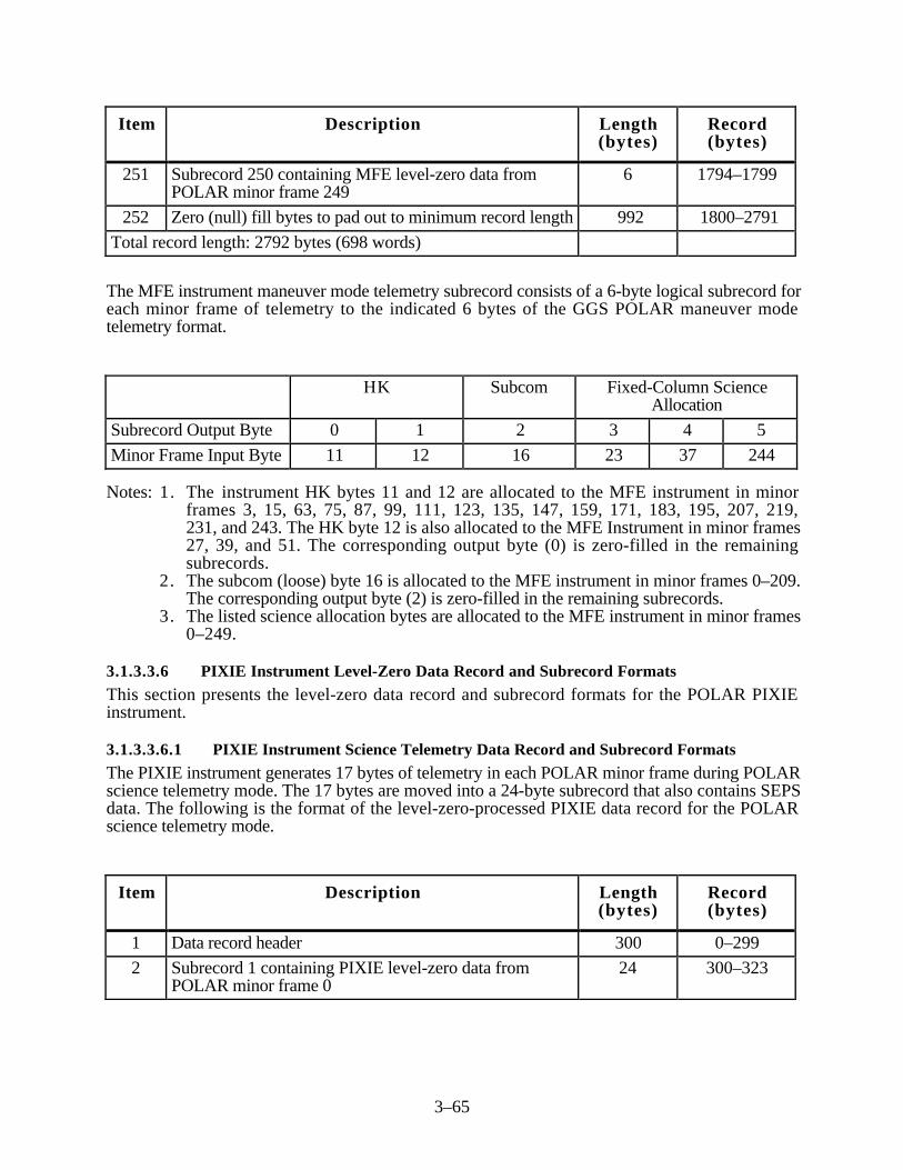
3–65
Item Description Length(bytes)
Record(bytes)
251 Subrecord 250 containing MFE level-zero data fromPOLAR minor frame 249
6 1794–1799
252 Zero (null) fill bytes to pad out to minimum record length 992 1800–2791
Total record length: 2792 bytes (698 words)
The MFE instrument maneuver mode telemetry subrecord consists of a 6-byte logical subrecord foreach minor frame of telemetry to the indicated 6 bytes of the GGS POLAR maneuver modetelemetry format.
HK Subcom Fixed-Column ScienceAllocation
Subrecord Output Byte 0 1 2 3 4 5
Minor Frame Input Byte 11 12 16 23 37 244
Notes: 1. The instrument HK bytes 11 and 12 are allocated to the MFE instrument in minorframes 3, 15, 63, 75, 87, 99, 111, 123, 135, 147, 159, 171, 183, 195, 207, 219,231, and 243. The HK byte 12 is also allocated to the MFE Instrument in minor frames27, 39, and 51. The corresponding output byte (0) is zero-filled in the remainingsubrecords.
2. The subcom (loose) byte 16 is allocated to the MFE instrument in minor frames 0–209.The corresponding output byte (2) is zero-filled in the remaining subrecords.
3. The listed science allocation bytes are allocated to the MFE instrument in minor frames0–249.
3.1.3.3.6 PIXIE Instrument Level-Zero Data Record and Subrecord Formats
This section presents the level-zero data record and subrecord formats for the POLAR PIXIEinstrument.
3.1.3.3.6.1 PIXIE Instrument Science Telemetry Data Record and Subrecord Formats
The PIXIE instrument generates 17 bytes of telemetry in each POLAR minor frame during POLARscience telemetry mode. The 17 bytes are moved into a 24-byte subrecord that also contains SEPSdata. The following is the format of the level-zero-processed PIXIE data record for the POLARscience telemetry mode.
Item Description Length(bytes)
Record(bytes)
1 Data record header 300 0–299
2 Subrecord 1 containing PIXIE level-zero data fromPOLAR minor frame 0
24 300–323

3–66
Item Description Length(bytes)
Record(bytes)
3 Subrecord 2 containing PIXIE level-zero data fromPOLAR minor frame 1
24 324–347
4–250 Subrecord 3–249 containing PIXIE level-zero data fromPOLAR minor frames 2–248
5928 348–6275
251 Subrecord 250 containing PIXIE level-zero data fromPOLAR minor frame 249
24 6276–6299
Total record length: 6300 bytes (1575 words)
The science telemetry subrecord format for PIXIE and SEPS consists of a 24-byte logicalsubrecord for each minor frame of telemetry. These 24 bytes correspond to the indicated 24 minorframe bytes of the GGS POLAR spacecraft telemetry format.
HK Subcom
Fixed-ColumnScienceAlloca-
tion
SubcomFixed-Column Science
Allocation
PIX/SEPS
SEPS SEPS SEPS PIX SEPS PIX
Subrecord Output Byte 0 1 2 3 4 5 6 7 8 9 10
Minor Frame Input Byte 11 12 17 19 38 40 41 42 43 44 93
Fixed-Column Science Allocation
PIX SEPS
Subrecord Output Byte 11 12 13 14 15 16 17 18 19 20 21 22 23
Minor Frame Input Byte 94 95 144 145 146 195 196 197 246 247 248 249 250
Notes: 1. PIXIE and SEPS share this format. The science allocation minor frame bytes 41, 42,43, 92, 93, 94, 143, 144, 194, 195, 196, 245, 246, and 247 are normally allocated toPIXIE. But, when PIXIE's high voltage is turned off to protect the instrument, thesebytes are allocated to SEPS.
2. The instrument HK byte 11 is allocated to the PIXIE instrument in minor frames 1, 4,7, 10, 13, 16, 19, 20, 22, 23, 24, 26, 27, 29, 30, 32, 33, 35, 36, 38, 39, 41, 42, 44,45, 47, 48, 49, 51, 54, 67, 73, 101, and 104. Byte 11 is allocated to SEPS in minorframes 31, 34, 46, 58, 70, 82, 94, 106, 118, 130, 142, 154, 166, 178, 190, 202,214, 226, and 238. Byte 12 is allocated to SEPS in minor frames 10, 22, 34, 46, 58,70, 82, 94, 106, 118, 130, 142, 154, 166, 178, 190, 202, 214, 226, and 238. Thecorresponding output byte (0) is zero-filled in the remaining subrecords.
3. The subcom (loose) byte 17 is allocated to the SEPS instrument in minor frames 139–249. The corresponding output byte (2) is zero-filled in the remaining subrecords.
4. The subcom (loose) byte 38 is allocated to the PIXIE instrument in minor frames 0, 2,3, 5, 6, 8, 9, 11, 12, 14, 15, 17, 18, 21, 25, 28, 31, 34, 37, 40, 43, 46, 50, 52, 53,
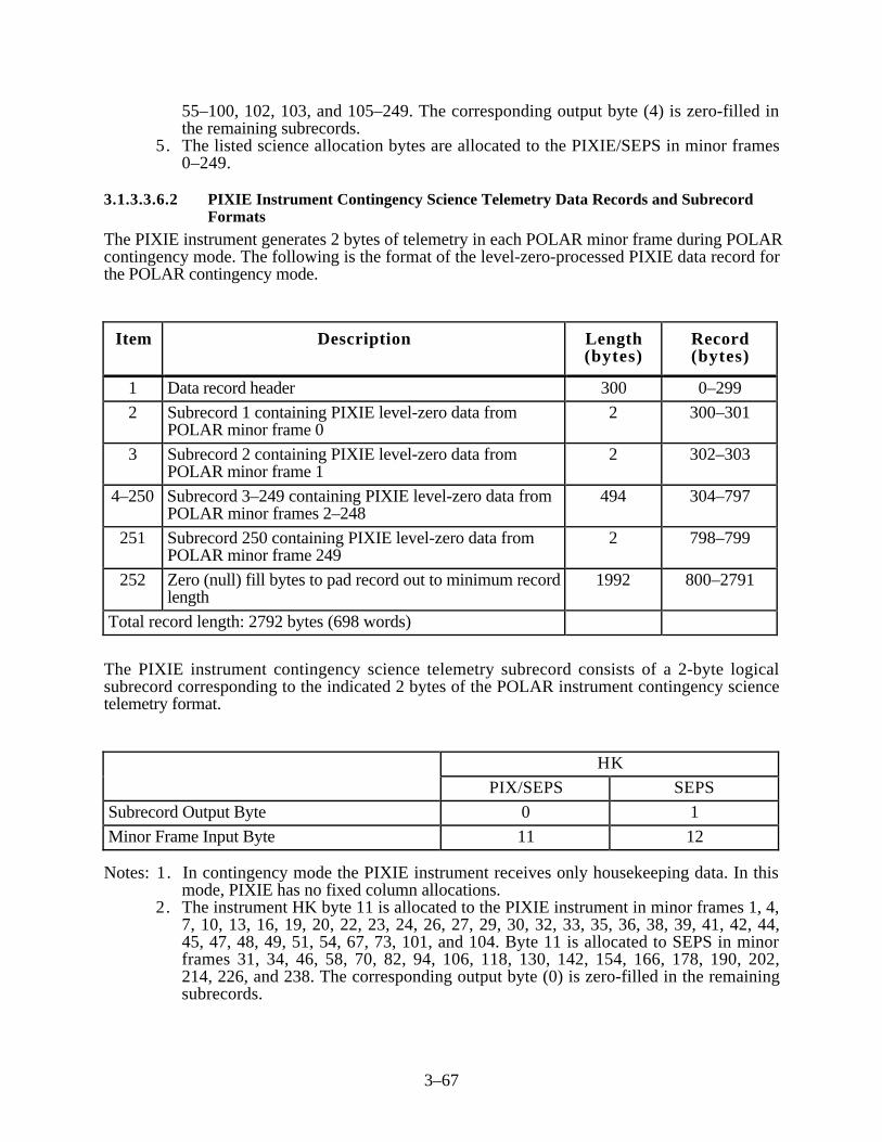
3–67
55–100, 102, 103, and 105–249. The corresponding output byte (4) is zero-filled inthe remaining subrecords.
5. The listed science allocation bytes are allocated to the PIXIE/SEPS in minor frames0–249.
3.1.3.3.6.2 PIXIE Instrument Contingency Science Telemetry Data Records and SubrecordFormats
The PIXIE instrument generates 2 bytes of telemetry in each POLAR minor frame during POLARcontingency mode. The following is the format of the level-zero-processed PIXIE data record forthe POLAR contingency mode.
Item Description Length(bytes)
Record(bytes)
1 Data record header 300 0–299
2 Subrecord 1 containing PIXIE level-zero data fromPOLAR minor frame 0
2 300–301
3 Subrecord 2 containing PIXIE level-zero data fromPOLAR minor frame 1
2 302–303
4–250 Subrecord 3–249 containing PIXIE level-zero data fromPOLAR minor frames 2–248
494 304–797
251 Subrecord 250 containing PIXIE level-zero data fromPOLAR minor frame 249
2 798–799
252 Zero (null) fill bytes to pad record out to minimum recordlength
1992 800–2791
Total record length: 2792 bytes (698 words)
The PIXIE instrument contingency science telemetry subrecord consists of a 2-byte logicalsubrecord corresponding to the indicated 2 bytes of the POLAR instrument contingency sciencetelemetry format.
HK
PIX/SEPS SEPS
Subrecord Output Byte 0 1
Minor Frame Input Byte 11 12
Notes: 1. In contingency mode the PIXIE instrument receives only housekeeping data. In thismode, PIXIE has no fixed column allocations.
2. The instrument HK byte 11 is allocated to the PIXIE instrument in minor frames 1, 4,7, 10, 13, 16, 19, 20, 22, 23, 24, 26, 27, 29, 30, 32, 33, 35, 36, 38, 39, 41, 42, 44,45, 47, 48, 49, 51, 54, 67, 73, 101, and 104. Byte 11 is allocated to SEPS in minorframes 31, 34, 46, 58, 70, 82, 94, 106, 118, 130, 142, 154, 166, 178, 190, 202,214, 226, and 238. The corresponding output byte (0) is zero-filled in the remainingsubrecords.

3–68
3. Byte 12 is allocated to SEPs in minor frames 10, 22, 34, 46, 58, 70, 82, 94, 106, 118,130, 142, 154, 166, 178, 190, 202, 214, 226, and 238. The corresponding outputbyte (0) is zero-filled in the remaining subrecords.
3.1.3.3.6.3 PIXIE Instrument Maneuver Mode Data Record and Subrecord Formats
The PIXIE instrument generates 5 bytes of telemetry in each minor frame during POLARmaneuver mode. The 5 bytes are moved into an 11-byte subrecord that also contains SEPS data.The following is the format of the level-zero-processed PIXIE data record for the POLARmaneuver mode.
Item Description Length(bytes)
Record(bytes)
1 Data record header 300 0–299
2 Subrecord 1 containing PIXIE level-zero data fromPOLAR minor frame 0
11 300–310
3 Subrecord 2 containing PIXIE level-zero data fromPOLAR minor frame 1
11 311–321
4–250 Subrecord 3–249 containing PIXIE level-zero data fromPOLAR minor frames 2–248
2717 322–3038
251 Subrecord 250 containing PIXIE level-zero data fromPOLAR minor frame 249
11 3039–3049
252 Zero fill bytes to pad record out to 4-byte word boundary 2 3050–3051
Total record length: 3052 bytes (763 words)
The PIXIE instrument maneuver mode telemetry subrecord consists of an 11-byte logicalsubrecord for each minor frame of telemetry to the indicated 11 bytes of the GGS POLARmaneuver mode telemetry format.
HK Subcom
Fixed-ColumnScienceAlloca-
tion
SubcomFixed-Column
ScienceAllocation
PIX/SEPS SEPS SEPS SEPS PIX SEPS
Subrecord Output Byte 0 1 2 3 4 5 6
Minor Frame Input Byte 11 12 17 19 38 40 41
Fixed-Column Science Allocation
PIX SEPS
Subrecord Output Byte 7 8 9 10
Minor Frame Input Byte 144 195 246 249

3–69
Notes: 1. PIXIE and SEPS share this format. The fixed column bytes 144, 195, and 246 arenormally allocated to PIXIE. But when PIXIE’s high voltage is turned off to protect theinstrument, these bytes are allocated to SEPS.
2. The instrument HK byte 11 is allocated to the PIXIE instrument in minor frames 1, 4,7, 10, 13, 16, 19, 20, 22, 23, 24, 26, 27, 29, 30, 32, 33, 35, 36, 38, 39, 41, 42, 44,45, 47, 48, 49, 51, 54, 67, 73, 101, and 104. Byte 11 is allocated to SEPS in minorframes 31, 34, 46, 58, 70, 82, 94, 106, 118, 130, 142, 154, 166, 178, 190, 202,214, 226, and 238. The corresponding output byte (0) is zero-filled in the remainingsubrecords.
3. Byte 12 is allocated to SEPS in minor frames 10, 22, 34, 46, 58, 70, 82, 94, 106,118, 130, 142, 154, 166, 178, 190, 202, 214, 226, 238. The corresponding outputbyte (1) is zero-filled in the remaining subrecord.
4. The subcom (loose) byte 17 is allocated to SEPS in minor frames 139–249. The outputbyte 2 will be zero-filled in the remaining subrecords.
5. The subcom (loose) byte 38 is allocated to the PIXIE instrument in minor frames 0, 2,3, 5, 6, 8, 9, 11, 12, 14, 15, 17, 18, 21, 25, 28, 31, 34, 37, 40, 43, 46, 50, 52, 53,55–100, 102, 103, and 105–249. The corresponding output byte (4) is zero-filled inthe remaining subrecords.
6. The listed science allocation bytes are allocated to the PIXIE/SEPS in major frames0–249.
3.1.3.3.7 PWI Level-Zero Data Record and Subrecord Formats
This section presents the level-zero data record and subrecord formats for the POLAR PWIinstrument.
3.1.3.3.7.1 PWI Science Telemetry Data Record and Subrecord Formats
The PWI generates 21 bytes of telemetry in each POLAR minor frame during POLAR sciencetelemetry mode. The following is the format of the level-zero-processed PWI record for thePOLAR science telemetry mode.
Item Description Length(bytes)
Record(bytes)
1 Data record header 300 0–299
2 Subrecord 1 containing PWI level-zero data from POLARminor frame 0
21 300–320
3 Subrecord 2 containing PWI level-zero data from POLARminor frame 1
21 321–341
4–250 Subrecord 3–249 containing PWI level-zero data fromPOLAR minor frames 2–248
5187 342–5528
251 Subrecord 250 containing PWI level-zero data fromPOLAR minor frame 249
21 5529–5549
252 Fill bytes to pad record out to 4-byte word boundary 2 5550–5551
Total record length: 5552 bytes (1388 words)

3–70
The PWI subrecord format consists of a 21-byte logical subrecord for each minor frame oftelemetry. These 21 bytes correspond to the indicated 21 minor frame bytes of the GGS POLARspacecraft telemetry format.
HK Sub-com
Fixed-Column Science Allocation
LowRate
Low andHigh Rate
HighRate
High Rate Low Rate High Rate
Subrecord Output Byte 0 1 2 3 4 5 6 7 8 9 10 11
Minor Frame Input Byte 11 12 14 64 65 66 88 89 90 112 113 114
Fixed-Column Science Allocation
Low Rate High Rate Low Rate
Subrecord Output Byte 12 13 14 15 16 17 18 19 20
Minor Frame Input Byte 136 137 138 168 169 170 232 233 234
Notes: 1. The instrument HK byte 11 is allocated to the PWI instrument (low rate) in minor frame0. HK byte 12 is allocated to the PWI low rate data in minor frames 0, 24, 48, 71, 72,95, 96, 119, 120, 143, 144, 167, 168, 191, 192, 215, and 216. HK byte 12 isallocated to PWI high rate data in minor frames 11, 12, 36, 59, 60, 83, 84, 107, 108,131, 132, 155, 156, 179, 180, 203, 204, 227, and 228. The corresponding bytes (0and 1) in the remaining subrecords will be zero-filled. Note: In addition, output byte 1in subrecords 247 and 248 will be filled from input byte 9 in minor frames 247 and248, respectively.
2. The subcom (loose) byte 14 is allocated to PWI (high rate) in minor frames 142–249.The corresponding output byte (2) is zero-filled in the minor frames 0–141.
3. The science allocation low rate data is in bytes 88, 89, 90, 136, 137, 138, 170, 232,233, and 234. The science allocation high rate data will be in bytes 64, 65, 66, 112,113, 114, 168, and 169.
4. The listed science allocation bytes are allocated to the PWI instrument in minor frames0–249.
3.1.3.3.7.2 PWI Contingency Science Telemetry Data Record and Subrecord Formats
The PWI generates 42 bytes of telemetry in each POLAR minor frame during POLAR contingencymode. The following is the format of the level-zero-processed PWI data record for the POLARcontingency mode.
Item Description Length(bytes)
Record(bytes)
1 Data record header 300 0–299
2 Subrecord 1 containing PWI level-zero data from POLARminor frame 0
42 300–341

3–71
Item Description Length(bytes)
Record(bytes)
3 Subrecord 2 containing PWI level-zero data from POLARminor frame 1
42 342–383
4–250 Subrecord 3–249 containing PWI level-zero data fromPOLAR minor frames 2–248
10,374 384–10,757
251 Subrecord 250 containing PWI level-zero data fromPOLAR minor frame 249
42 10,758–10,799
Total record length: 10,800 bytes (2700 words)
The PWI contingency science telemetry subrecord format consists of a 42-byte subrecordcorresponding to the indicated 42 bytes of the GGS POLAR instrument contingency sciencetelemetry subrecord format.
HK Fixed-Column Science Allocation
LowRate
Low andHigh Rate
High Rate
Subrecord Output Byte 0 1 2 3 4 5 6 7 8
Minor Frame Input Byte 11 12 13 14 15 33 34 35 53
Fixed-Column Science Allocation
High Rate Low Rate High Rate
Subrecord Output Byte 9 10 11 12 13 14 15 16 17
Minor Frame Input Byte 54 55 73 74 75 93 94 95 113
Fixed-Column Science Allocation
High Rate Low Rate High Rate
Subrecord Output Byte 18 19 20 21 22 23 24 25 26
Minor Frame Input Byte 114 115 133 134 135 153 154 155 173
Fixed-Column Science Allocation
High Rate
Subrecord Output Byte 27 28 29 30 31 32 33 34 35
Minor Frame Input Byte 174 175 189 190 191 205 206 207 219

3–72
Fixed-Column Science Allocation
High Rate Low Rate
Subrecord Output Byte 36 37 38 39 40 41
Minor Frame Input Byte 220 221 235 236 237 250
Notes: 1. The instrument HK byte 11 is allocated to the PWI (low rate) in minor frame 0. HKbyte 12 is allocated to the PWI low rate data in minor frames 0, 24, 48, 71, 72, 95, 96,119, 120, 143, 144, 167, 168, 191, 192, 215, 216, 239, and 240. HK byte 12 isallocated to PWI high rate data in minor frames 11, 12, 36, 59, 60, 83, 84, 107, 108,131, 132, 155, 156, 179, 180, 203, 204, 227, and 228. The corresponding bytes (0and 1) in the remaining subrecords will be zero-filled.
2. The science allocation low rate data is in bytes 93–95, 133–135, 235–237, and 250.The science allocation high rate data is in bytes 13–15, 33–35, 53–55, 73–75, 113–115, 153–155, 173–175, 189–191, 205–207, and 219–221.
3. The listed science allocation bytes are allocated to the PWI instrument in minor frames0–249.
3.1.3.3.7.3 PWI Maneuver Mode Data Record and Subrecord Formats
The PWI instrument generates 21 bytes of telemetry in each minor frame during POLAR maneuvermode. The following is the format of the level-zero-processed PWI data record for the POLARmaneuver mode.
Item Description Length(bytes)
Record(bytes)
1 Data record header 300 0–299
2 Subrecord 1 containing PWI level-zero data from POLARminor frame 0
21 300–320
3 Subrecord 2 containing PWI level-zero data from POLARminor frame 1
21 321–341
4–250 Subrecord 3–249 containing PWI level-zero data fromPOLAR minor frames 2–248
5187 342–5528
251 Subrecord 250 containing PWI level-zero data fromPOLAR minor frame 249
21 5529–5549
252 Fill bytes to pad record out to 4-byte word boundary 2 5550–5551
Total record length: 5552 bytes (1388 words)
The PWI maneuver mode telemetry subrecord consists of a 21-byte logical subrecord for eachminor frame of telemetry to the indicated 21 bytes of the GGS POLAR maneuver mode telemetryformat.

3–73
HK Subcom Fixed-Column Science Allocation
LowRate
Low andHigh Rate
HighRate
High Rate Low Rate High Rate
Subrecord Output Byte 0 1 2 3 4 5 6 7 8 9 10 11
Minor Frame Input Byte 11 12 14 64 65 66 88 89 90 112 113 114
Fixed-Column Science Allocation
Low Rate High Rate Low Rate
Subrecord Output Byte 12 13 14 15 16 17 18 19 20
Minor Frame Input Byte 136 137 138 168 169 170 232 233 234
Notes: 1. The instrument HK byte 11 is allocated to the PWI (low rate) in minor frame 0. HKbyte 12 is allocated to the PWI low rate data in minor frames 0, 24, 48, 71, 72, 95, 96,119, 120, 143, 144, 167, 168, 191, 192, 215, 216, 239, and 240. HK byte 12 isallocated to PWI high rate data in minor frames 11, 12, 36, 59, 60, 83, 84, 107, 108,131, 132, 155, 156, 179, 180, 203, 204, 227, and 228. The corresponding bytes (0and 1) in the remaining subrecords will be zero-filled.
2. The subcom (loose) byte 14 is allocated to the PWI and contains high rate data in minorframes 142–249. The corresponding output byte (2) is zero-filled in the minor frames0–141.
3. The science allocation low rate data is in bytes 88–90, 136–138, 170, and 232–234.The science allocation high rate data will be in bytes 64–66, 112–114, 168, and 169.
4. The listed science allocation bytes are allocated to the PWI instrument in minor frames0–249.
3.1.3.3.8 SEPS Instrument Level-Zero Data Record and Subrecord Formats
This section presents the level-zero data record and subrecord formats for the POLAR SEPSinstrument.
3.1.3.3.8.1 SEPS Instrument Science Telemetry Data Record and Subrecord Formats
The SEPS instrument generates 8 bytes of telemetry in each POLAR minor frame during POLARscience telemetry mode. The 8 bytes are moved into a 24-byte subrecord that also contains PIXIEdata. The following is the format of the level-zero-processed SEPS data record for the POLARscience telemetry mode.
Item Description Length(bytes)
Record(bytes)
1 Data record header 300 0–299
2 Subrecord 1 containing SEPS level-zero data fromPOLAR minor frame 0
24 300–323
3 Subrecord 2 containing SEPS level-zero data fromPOLAR minor frame 1
24 324–347

3–74
Item Description Length(bytes)
Record(bytes)
4–250 Subrecord 3–249 containing SEPS level-zero data fromPOLAR minor frames 2–248
5928 348–6275
251 Subrecord 250 containing SEPS level-zero data fromPOLAR minor frame 249
24 6276–6299
Total record length: 6300 bytes (1575 words)
The SEPS instrument science telemetry subrecord format consists of a 24-byte logical subrecordfor each minor frame of telemetry. The 24 bytes correspond to the indicated 24 minor frame bytesof the GGS POLAR spacecraft telemetry format.
HK Subcom FixedColumn
Subcom Fixed-Column ScienceAllocation
PIX/SEPS
SEPS SEPS SEPS PIX SEPS PIX
Subrecord Output Byte 0 1 2 3 4 5 6 7 8 9 10
Minor Frame Input Byte 11 12 17 19 38 40 41 42 43 44 93
Fixed-Column Science Allocation
PIX SEPS
Subrecord Output Byte 11 12 13 14 15 16 17 18 19 20 21 22 23
Minor Frame Input Byte 94 95 144 145 146 195 196 197 246 247 248 249 250
Notes: 1. The PIXIE and SEPS instruments share this format. SEPS is always allocated bytes19, 40, 41, 249, and 250. It also allocated bytes 42, 43, 44, 93, 94, 144, 145, 195,196, 197, 246, 247, and 248 when PIXIE's high voltage is turned off to protect theinstrument.
2. The instrument HK bytes 11 and 12 are allocated to the SEPS instrument in minorframes 34, 46, 58, 70, 82, 94, 106, 118, 130, 142, 154, 166, 178, 190, 202, 214,226, and 238. HK byte 12 is also allocated to the SEPS instrument in minor frames 10and 22. HK byte 11 is also allocated to SEPS in minor frame 31. The correspondingoutput bytes (0 and 1) are zero-filled in the remaining subrecords with the followingexception. Byte 11 is allocated to PIXIE in minor frames 1, 4, 7, 10, 13, 16, 19, 20,22, 23, 24, 26, 27, 29, 30, 32, 33, 35, 36, 38, 39, 41, 42, 44, 45, 47, 48, 49, 51,54, 67, 73, 101, and 104.
3. The subcom (loose) byte 17 is allocated to the SEPS instrument in minor frames 139–249. The corresponding output byte (2) is zero-filled in the remaining subrecords.
4. Byte 38 is allocated to PIXIE minor frames 0, 2, 3, 5, 6, 8,. 9, 11, 12, 14, 15, 17, 18,21, 25, 28, 31, 34, 37, 40, 43, 46, 50, 52, 53, 55–100, 102, 103, and 105–249.
5. The listed science allocation bytes are allocated to the PIXIE/SEPS instruments inminor frames 0–249.

3–75
3.1.3.3.8.2 SEPS Instrument Contingency Science Telemetry Data Record and SubrecordFormats
The SEPS instrument generates 2 bytes of telemetry in each POLAR minor frame during POLARcontingency mode. The following is the format of the level-zero-processed SEPS data record forthe POLAR contingency mode.
Item Description Length(bytes)
Record(bytes)
1 Data record header 300 0–299
2 Subrecord 1 containing SEPS level-zero data fromPOLAR minor frame 0
2 300–301
3 Subrecord 2 containing SEPS level-zero data fromPOLAR minor frame 1
2 302–303
4–250 Subrecord 3–249 containing SEPS level-zero data fromPOLAR minor frames 2–248
494 304–797
251 Subrecord 250 containing SEPS level-zero data fromPOLAR minor frame 249
2 798–799
252 Zero (null) fill bytes to pad record out to the minimumrecord length
1992 800–2791
Total record length: 2792 bytes (698 words)
The SEPS instrument contingency science telemetry subrecord format consists of a 2-bytesubrecord corresponding to the indicated 2 bytes of the GGS POLAR instrument contingencyscience telemetry subrecord format.
HK
Subrecord Output Byte 0 1
Minor Frame Input Byte 11 12
Notes: 1. In contingency mode, the SEPS instrument receives only housekeeping data.2. The instrument HK byte 11 is allocated to the PIXIE instrument in minor frames 1, 4,
7, 10, 13, 16, 19, 20, 22, 23, 24, 26, 27, 29, 30, 32, 33, 35, 36, 38, 39, 41, 42, 44,45, 47, 48, 49, 51, 54, 67, 73, 101, and 104. Byte 11 is allocated to SEPS in minorframes 31, 34, 46, 58, 70, 82, 94, 106, 118, 130, 142, 154, 166, 178, 190, 202,214, 226, and 238. The corresponding output byte (0) is zero-filled in the remainingsubrecords.
3.1.3.3.8.3 SEPS Instrument Maneuver Mode Data Record and Subrecord Formats
The SEPS instrument generates 7 bytes of telemetry in each minor frame during POLAR maneuvermode. These 7 bytes are moved into an 11-byte subrecord shared with PIXIE. The following is theformat of the level-zero-processed SEPS data record for the POLAR maneuver mode.

3–76
Item Description Length(bytes)
Record(bytes)
1 Data record header 300 0–299
2 Subrecord 1 containing SEPS level-zero data fromPOLAR minor frame 0
11 300–310
3 Subrecord 2 containing SEPS level-zero data fromPOLAR minor frame 1
11 311–321
4–250 Subrecord 3–249 containing SEPS level-zero data fromPOLAR minor frames 2–248
2717 322–3038
251 Subrecord 250 containing SEPS level-zero data fromPOLAR minor frame 249
11 3039–3049
252 Zero (null) fill bytes to pad record out to 4-byte wordboundary
2 3050–3051
Total record length: 3052 bytes (763 words)
The SEPS instrument maneuver mode telemetry subrecord consists of an 11-byte logical subrecordfor each minor frame of telemetry to the indicated 11 bytes of the GGS POLAR maneuver modetelemetry format.
HK Subcom
Fixed-ColumnScienceAlloca-
tion
SubcomFixed-Column
ScienceAllocation
PIX/SEPS SEPS SEPS SEPS PIX SEPS
Subrecord Output Byte 0 1 2 3 4 5 6
Minor Frame Input Byte 11 12 17 19 38 40 41
Fixed-Column Science Allocation
PIX SEPS
Subrecord Output Byte 7 8 9 10
Minor Frame Input Byte 144 195 246 249
Notes: 1. The PIXIE and SEPS instruments share this format. SEPS is always allocated bytes19, 40, 41, and 249. It also is allocated bytes 42, 43, 44, 144, 195, and 246, whenPIXIE's high voltage is turned off to protect the instrument.
2. The instrument HK bytes 11 and 12 are allocated to the SEPS instrument in minorframes 34, 46, 58, 70, 82, 94, 106, 118, 130, 142, 154, 166, 177, 190, 202, 214,226, and 238. HK byte 12 is also allocated to the SEPS instrument in minor frames 10and 22. HK byte 11 is also allocated to SEPS minor frame 31. The correspondingoutput bytes (0 and 1) are zero-filled in the remaining subrecords with the followingexception. Byte 11 is allocated to PIXIE in minor frames 1, 4, 7, 10, 13, 16, 19, 20,

3–77
22, 24, 26, 27, 29, 30, 32, 33, 35, 36, 38, 39, 41, 42, 44, 45, 47, 48, 49, 51, 54,56, 67, 73, 101, and 104.
3. The subcom (loose) byte 17 is allocated to the SEPS instrument in minor frames 140–250. The corresponding output byte (2) is zero-filled in the remaining subrecords.
4. The listed science allocation bytes are allocated to the PIXIE/SEPS instruments inminor frames 0–249.
3.1.3.3.9 TIDE Instrument Level-Zero Data Record and Subrecord Formats
This section presents the level-zero data records and subrecord formats for the POLAR TIDEinstrument.
3.1.3.3.9.1 TIDE Instrument Science Telemetry Data Record and Subrecord Formats
The TIDE instrument generates 22 bytes of telemetry in each POLAR minor frame during POLARscience telemetry mode. The following is the format of the level-zero-processed TIDE data recordfor the POLAR science telemetry mode.
Item Description Length(bytes)
Record(bytes)
1 Data record header 300 0–299
2 Subrecord 1 containing TIDE level-zero data fromPOLAR minor frame 0
22 300–321
3 Subrecord 2 containing TIDE level-zero data fromPOLAR minor frame 1
22 322–343
4–250 Subrecord 3–249 containing TIDE level-zero data fromPOLAR minor frames 2–248
5434 344–5777
251 Subrecord 250 containing TIDE level-zero data fromPOLAR minor frame 249
22 5778–5799
Total record length: 5800 bytes (1450 words)
The TIDE instrument science telemetry subrecord format consists of a 22-byte logical subrecordfor each minor frame of telemetry. These 22 bytes correspond to the indicated 22 minor framebytes of the GGS POLAR spacecraft telemetry format.
HK Subcom Fixed-Column Science Allocation
Subrecord Output Byte 0 1 2 3 4 5 6 7
Minor Frame Input Byte 10 11 12 13 48 49 50 72
Fixed-Column Science Allocation
Subrecord Output Byte 8 9 10 11 12 13 14 15
Minor Frame Input Byte 73 74 96 97 98 120 121 122

3–78
Fixed-Column Science Allocation
Subrecord Output Byte 16 17 18 19 20 21
Minor Frame Input Byte 152 153 154 176 177 178
Notes: 1. The spacecraft HK byte 10 is allocated to the TIDE instrument in minor frames 7, 8,57, 58, 107, 108, 157, 158, 207, and 208. The corresponding output byte (0) is zero-filled in the remaining subrecords.
2. The instrument HK bytes 11 and 12 are allocated to the TIDE instrument in minorframes 5, 17, 53, 65, 77, 89, 113, 125, 137, 149 161, 173, 185, 197, 209, 221, 233,and 245. HK byte 11 is also allocated to the TIDE instrument in minor frames 61, 79,85, 91, 97, 103, and 134. HK byte 12 is also allocated to the TIDE instrument in minorframes 29, 41, and 101. The corresponding output bytes (1 and 2) are zero-filled in theremaining subrecords.
3. The subcom (loose) byte 13 is allocated to the TIDE instrument in minor frames142–249. The corresponding output byte (3) is zero-filled in the remaining subrecords.
4. The listed science allocation bytes are allocated to the TIDE instrument in minor frames0–249.
3.1.3.3.9.2 TIDE Instrument Contingency Science Telemetry Data Record and SubrecordFormats
The TIDE instrument generates 43 bytes of telemetry in each POLAR minor frame during POLARcontingency mode. The following is the format of the level-zero-processed TIDE data record forthe POLAR contingency mode.
Item Description Length(bytes)
Record(bytes)
1 Data record header 300 0–299
2 Subrecord 1 containing TIDE level-zero data fromPOLAR minor frame 0
43 300–342
3 Subrecord 2 containing TIDE level-zero data fromPOLAR minor frame 1
43 343–385
4–250 Subrecord 3–249 containing TIDE level-zero data fromPOLAR minor frames 2–248
10,621 386–11,006
251 Subrecord 250 containing TIDE level-zero data fromPOLAR minor frame 249
43 11,007–11,049
252 Zero (null) fill bytes to pad record out to 4-byte wordboundary
2 11,050–11,051
Total record length: 11,052 bytes (2763 words)
The TIDE instrument contingency science telemetry subrecord format consists of a 43-byte logicalsubrecord corresponding to the indicated 43 bytes of the GGS POLAR instrument contingencysubrecord format.

3–79
HK Fixed-Column Science Allocation
Subrecord Output Byte 0 1 2 3 4 5 6 7 8 9
Minor Frame Input Byte 10 11 12 17 18 19 37 38 39 57
Fixed-Column Science Allocation
Subrecord Output Byte 10 11 12 13 14 15 16 17 18 19
Minor Frame Input Byte 58 59 77 78 79 97 98 99 117 118
Fixed-Column Science Allocation
Subrecord Output Byte 20 21 22 23 24 25 26 27 28 29 30
Minor Frame Input Byte 119 137 138 139 157 158 159 177 178 179 193
Fixed-Column Science Allocation
Subrecord Output Byte 31 32 33 34 35 36 37 38 39 40 41 42
Minor Frame Input Byte 194 195 208 209 210 224 225 226 238 239 240 252
Notes: 1. The spacecraft HK byte 10 is allocated to the TIDE instrument in minor frames 7, 8,57, 58, 107, 108, 207, and 208. The corresponding output byte (0) is zero-filled in theremaining subrecords
2. The instrument HK bytes 11 and 12 are allocated to the TIDE instrument in minorframes 5, 17, 53, 65, 77, 89, 113, 125, 137, 149, 161, 173, 185, 197, 209, 221,233, and 245. HK byte 11 is also allocated to the TIDE instrument in minor frames 61,79, 85, 91, 97, 103, and 134. HK byte 12 is also allocated to the TIDE instrument inminor frames 29, 41, and 101. The corresponding output bytes (1 and 2) are zero-filledin the remaining subrecords.
3. The listed science allocation bytes are allocated to the TIDE instrument in minor frames0–249.
3.1.3.3.9.3 TIDE Instrument Maneuver Mode Data Record and Subrecord Formats
The TIDE instrument generates 22 bytes of telemetry in each minor frame during POLARmaneuver mode. The following is the format of the level-zero-processed TIDE data record for thePOLAR maneuver mode.
Item Description Length(bytes)
Record(bytes)
1 Data record header 300 0–299
2 Subrecord 1 containing TIDE level-zero data fromPOLAR minor frame 0
22 300–321
3 Subrecord 2 containing TIDE level-zero data fromPOLAR minor frame 1
22 322–343

3–80
4–250 Subrecord 3–249 containing TIDE level-zero data fromPOLAR minor frames 2–248
5434 344–5777
251 Subrecord 250 containing TIDE level-zero data fromPOLAR minor frame 249
22 5778–5799
Total record length: 5800 bytes (1450 words)
The TIDE instrument maneuver mode telemetry subrecord consists of a 22-byte logical subrecordfor each minor frame of telemetry to the indicated 22 bytes of the GGS POLAR maneuver modetelemetry format.
HK Subcom Fixed-Column Science Allocation
Subrecord Output Byte 0 1 2 3 4 5 6 7
Minor Frame Input Byte 10 11 12 13 48 49 50 72
Fixed-Column Science Allocation
Subrecord Output Byte 8 9 10 11 12 13 14 15
Minor Frame Input Byte 73 74 96 97 98 120 121 122
Fixed-Column Science Allocation
Subrecord Output Byte 16 17 18 19 20 21
Minor Frame Input Byte 152 153 154 176 177 178
Notes: 1. The instrument HK byte 10 is allocated to the TIDE instrument in minor frames 7, 8,57, 58, 107, 108, 157, 158, 207, and 208. The corresponding output byte 0 is zero-filled in the remaining subrecords.
2. The instrument HK bytes 11 and 12 are allocated to the TIDE instrument in minorframes 5, 17, 53, 65, 77, 89, 113, 125, 137, 149, 161, 173, 185, 197, 209, 221,233, and 245. HK byte 11 is also allocated to the TIDE instrument in minor frames 61,79, 85, 91, 97, 103, and 134. HK byte 12 is also allocated to the TIDE instrument inminor frames 29, 41, and 101. The corresponding output bytes (1 and 2) are zero-filledin the remaining subrecords.
3. The subcom (loose) byte 13 is allocated to the TIDE instrument in minor frames142–249. The corresponding output byte (3) is zero-filled in the remaining subrecords.
4. The listed science allocation bytes are allocated to the TIDE instrument in minor frames0–249.
3.1.3.3.10 TIMAS Instrument Level-Zero Data Record and Subrecord Formats
This section presents the level-zero data record and subrecord formats for POLAR TIMASinstrument.
3.1.3.3.10.1 TIMAS Instrument Science Telemetry Data Record and Subrecord Formats
The TIMAS instrument generates 21 bytes of telemetry in each POLAR minor frame duringPOLAR science telemetry mode. The following is the format of the level-zero-processed TIMASdata record for the POLAR science telemetry mode.

3–81
Item Description Length(bytes)
Record(bytes)
1 Data record header 300 0–299
2 Subrecord 1 containing TIMAS level-zero data fromPOLAR minor frame 0
21 300–320
3 Subrecord 2 containing TIMAS level-zero data fromPOLAR minor frame 1
21 332–341
4–250 Subrecord 3–249 containing TIMAS level-zero data fromPOLAR minor frames 2–248
5187 342–5528
251 Subrecord 250 containing TIMAS level-zero data fromPOLAR minor frame 249
21 5529–5549
252 Fill bytes to pad record out to 4-byte word boundary 2 5550–5551
Total record length: 5552 bytes (1388 words)
The TIMAS instrument science telemetry subrecord format consists of a 21-byte logical subrecordfor each minor frame of telemetry. These 21 bytes correspond to the indicated 21 minor framebytes of the GGS POLAR spacecraft telemetry format.
HK Fixed-Column Science Allocation
Subrecord Output Byte 0 1 2 3 4 5 6 7 8 9 10
Minor Frame Input Byte 11 12 21 31 32 33 56 57 58 80 81
Fixed-Column Science Allocation
Subrecord Output Byte 11 12 13 14 15 16 17 18 19 20
Minor Frame Input Byte 82 104 105 106 128 129 130 160 161 162
Notes: 1. The instrument HK bytes 11 and 12 are allocated to the TIMAS instrument in minorframes 6, 18, 66, 78, 90, 102, 114, 126, 138, 150, 162, 174, 186, 198, 210, 222,234, and 246. HK byte 11 is allocated to the TIMAS instrument in minor frames 109,115, 121, 127, and 133. HK byte 12 is allocated to TIMAS in minor frames 30, 42,and 54. The corresponding output bytes (0 and 1) are zero-filled in the remainingsubrecords.
2. The listed science allocation bytes are allocated to the TIMAS instrument in minorframes 0–249.
3.1.3.3.10.2 TIMAS Instrument Contingency Science Telemetry Data Record and SubrecordFormats
The TIMAS instrument generates 41 bytes of telemetry in each POLAR minor frame duringPOLAR contingency mode. The following is the format of the level-zero-processed TIMAS datarecord for the POLAR contingency mode.

3–82
Item Description Length(bytes)
Record(bytes)
1 Data record header 300 0–299
2 Subrecord 1 containing TIMAS level-zero data fromPOLAR minor frame 0
41 300–340
3 Subrecord 2 containing TIMAS level-zero data fromPOLAR minor frame 1
41 341–381
4–250 Subrecord 3–249 containing TIMAS level-zero data fromPOLAR minor frames 2–248
10,127 382–10,508
251 Subrecord 250 containing TIMAS level-zero data fromPOLAR minor frame 249
41 10,509–10,549
252 Fill bytes to pad record out to 4-byte word boundary 2 10,550–10,551
Total record length: 10,552 bytes (2638 words)
The TIMAS instrument contingency science telemetry subrecord format consists of a 41-bytelogical subrecord corresponding to the indicated 41 bytes of the GGS POLAR spacecraftcontingency telemetry format.
HK Fixed-Column Science Allocation
Subrecord Output Byte 0 1 2 3 4 5 6 7 8 9
Minor Frame Input Byte 11 12 21 22 23 41 42 43 61 62
Fixed-Column Science Allocation
Subrecord Output Byte 11 11 12 13 14 15 16 17 18 19
Minor Frame Input Byte 63 81 82 83 101 102 103 121 122 123
Fixed-Column Science Allocation
Subrecord Output Byte 20 21 22 23 24 25 26 27 28 29
Minor Frame Input Byte 141 142 143 161 162 163 181 182 183 197
Fixed-Column Science Allocation
Subrecord Output Byte 30 31 32 33 34 35 36 37 38 39 40
Minor Frame Input Byte 198 199 213 214 215 227 228 229 244 245 246
Notes: 1. The instrument HK bytes 11 and 12 are allocated to the TIMAS instrument in minorframes 6, 18, 66, 78, 90, 102, 114, 126, 138, 150, 162, 174, 186, 198, 210, 222,234, and 246. HK byte 11 also is allocated to the TIMAS instruments in minor frames109, 115, 121, 127, and 133. HK byte 12 also is allocated to the TIMAS instrument inminor frames 30, 42, and 54. The corresponding output bytes (0 and 1) are zero-filledin the remaining subrecords.

3–83
2. The listed science allocation bytes are allocated to the TIMAS instrument in minorframes 0–249.
3.1.3.3.10.3 TIMAS Instrument Maneuver Mode Data Record and Subrecord Formats
The TIMAS instrument generates 21 bytes of telemetry in each minor frame during POLARmaneuver mode. The following is the format of the level-zero-processed TIMAS data record forthe POLAR maneuver mode.
Item Description Length(bytes)
Record(bytes)
1 Data record header 300 0–299
2 Subrecord 1 containing TIMAS level-zero data fromPOLAR minor frame 0
21 300–320
3 Subrecord 2 containing TIMAS level-zero data fromPOLAR minor frame 1
21 321–341
4–250 Subrecord 3–249 containing TIMAS level-zero data fromPOLAR minor frames 2–248
5187 342–5528
251 Subrecord 250 containing TIMAS level-zero data fromPOLAR minor frame 249
21 5529–5549
252 Fill bytes to pad record out to 4-byte word boundary 2 5550–5551
Total record length: 5552 bytes (1388 words)
The TIMAS instrument maneuver mode telemetry subrecord consists of a 21-byte logicalsubrecord for each minor frame of telemetry to the indicated 21 bytes of the GGS POLARmaneuver mode telemetry format.
HK Fixed-Column Science Allocation
Subrecord Output Byte 0 1 2 3 4 5 6 7 8 9 10
Minor Frame Input Byte 11 12 21 30 32 33 56 57 58 80 81
Fixed-Column Science Allocation
Subrecord Output Byte 11 12 13 14 15 16 17 18 19 20
Minor Frame Input Byte 82 104 105 106 128 129 130 160 161 162
Notes: 1. The instrument HK bytes 11 and 12 are allocated to the TIMAS instrument in minorframes 6, 18, 66, 78, 90, 102, 114, 126, 138, 150, 162, 174, 186, 198, 210, 222,234, and 246. HK byte 11 is allocated to the TIMAS instrument in minor frames 109,115, 121, 127, and 133. HK byte 12 also is allocated to the TIMAS instrument inminor frames 30, 42, and 54. The corresponding output bytes (0 and 1) are zero-filledin the remaining subrecords.
2. The listed science allocation bytes are allocated to the TIMAS instrument in minorframes 0–249.

3–84
3.1.3.3.11 UVI Instrument Level-Zero Data Record and Subrecord Formats
This section presents the level-zero data record and subrecord formats for the POLAR UVIinstrument.
3.1.3.3.11.1 UVI Instrument Science Telemetry Data Record and Subrecord Formats
The UVI instrument generates 58 bytes of telemetry in each POLAR minor frame during POLARscience telemetry mode. The following is the format of the level-zero-processed UVI data recordfor the POLAR science telemetry mode.
Item Description Length(bytes)
Record(bytes)
1 Data record header 300 0–299
2 Subrecord 1 containing UVI level-zero data from POLARminor frame 0
58 300–357
3 Subrecord 2 containing UVI level-zero data from POLARminor frame 1
58 358–415
4–250 Subrecord 3–249 containing UVI level-zero data fromPOLAR minor frames 2–248
14,326 416–14,741
251 Subrecord 250 containing UVI level-zero data fromPOLAR minor frame 249
58 14,742–14,799
Total record length: 14,800 bytes (3700 words)
The UVI instrument science telemetry subrecord format consists of a 58-byte logical subrecord foreach minor frame of telemetry. These 58 bytes correspond to the indicated 56 minor frame bytes ofthe GGS POLAR spacecraft telemetry format.
HK Subcom Fixed-Column Science Allocation
Subrecord Output Byte 0 1 2 3 4 5 6 7 8 9
Minor Frame Input Byte 11 14 38 18 22 26 30 34 47 51
Fixed-Column Science Allocation
Subrecord Output Byte 10 11 12 13 14 15 16 17 18 19
Minor Frame Input Byte 55 59 63 67 71 75 79 83 87 91
Fixed-Column Science Allocation
Subrecord Output Byte 20 21 22 23 24 25 26 27 28 29
Minor Frame Input Byte 99 103 107 111 115 119 123 127 131 135

3–85
Fixed-Column Science Allocation
Subrecord Output Byte 30 31 32 33 34 35 36 37 38 39
Minor Frame Input Byte 139 143 147 151 155 159 163 167 171 175
Fixed-Column Science Allocation
Subrecord Output Byte 40 41 42 43 44 45 46 47 48 49
Minor Frame Input Byte 179 183 187 191 199 203 207 211 215 219
Fixed-Column Science Allocation
Subrecord Output Byte 50 51 52 53 54 55 56 57
Minor Frame Input Byte 223 227 231 235 239 243 251 255
Notes: 1. The instrument HK byte 11 is allocated to the UVI instrument in minor frames 2, 14,28, 37, 40, 43, 50, 52, 57, 62, 64, 74, 76, 86, 88, 98, 100, 110, 112, 122, 124, 146,148, 158, 160, 170, 172, 182, 184, 194, 196, 206, 208, 218, 220, 230, 232, 242,and 244. The corresponding output byte (0) is zero-filled in the remaining subrecords.
2. The subcom (loose) byte 14 is allocated to the UVI instrument in minor frames 125–141. The corresponding output byte 1 will be zero-filled in the remaining subrecords.
3. The subcom (loose) byte (38) is allocated to the UVI instrument in minor frames 1, 4,7, 10, 13, 16, 19, 20, 22, 23, 24, 26, 27, 29, 30, 32, 33, 35, 36, 38, 39, 41, 42, 44,45, 47, 48, 49, 51, 54, 101, and 104. The corresponding output byte is zero-filled inthe remaining subrecords.
4. The listed science allocation bytes are allocated to the UVI instrument in minor frames0–249.
3.1.3.3.11.2 UVI Instrument Contingency Science Telemetry Data Record and SubrecordFormats
The UVI instrument generates 1 byte of telemetry in each POLAR minor frame during POLARcontingency mode. The following is the format of the level-zero-processed UVI data record for thePOLAR contingency mode.
Item Description Length(bytes)
Record(bytes)
1 Data record header 300 0–299
2 Subrecord 1 containing UVI level-zero data from POLARminor frame 0
1 300
3 Subrecord 2 containing UVI level-zero data from POLARminor frame 1
1 301
4–250 Subrecord 3–249 containing UVI level-zero data fromPOLAR minor frames 2–248
247 302–548

3–86
Item Description Length(bytes)
Record(bytes)
251 Subrecord 250 containing UVI level-zero data fromPOLAR minor frame 249
1 549
252 Fill bytes to pad record out to the minimum record length 2242 550–2791
Total record length: 2792 bytes (698 words)
The UVI instrument contingency science telemetry subrecord format consists of a 1-byte logicalsubrecord corresponding to the following byte of the GGS POLAR instrument contingencysubrecord format.
HK
Subrecord Output Byte 0
Minor Frame Input Byte 11
Notes: 1. The instrument HK byte 11 is allocated to the UVI instrument in minor frames 2, 14,28, 37, 40, 43, 50, 52, 57, 62, 64, 74, 76, 86, 88, 98, 100, 110, 112, 122, 124, 146,148, 158, 160, 170, 172, 182, 184, 194, 196, 206, 208, 218, 220, 230, 232, 242,and 244. The corresponding output byte 0 is zero-filled in the remaining subrecords.
2. UVI does not have a fixed column allocation during contingency science mode.
3.1.3.3.11.3 UVI Instrument Maneuver Mode Data Record and Subrecord Formats
The UVI instrument generates 49 bytes of telemetry in each minor frame during POLAR maneuvermode. The following is the format of the level-zero-processed UVI data record during POLARmaneuver mode.
Item Description Length(bytes)
Record(bytes)
1 Data record header 300 0–299
2 Subrecord 1 containing UVI level-zero data from POLARminor frame 0
49 300–348
3 Subrecord 2 containing UVI level-zero data from POLARminor frame 1
49 349–397
4–250 Subrecord 3–249 containing UVI level-zero data fromPOLAR minor frames 2–248
12,103 398–12,500
251 Subrecord 250 containing UVI level-zero data fromPOLAR minor frame 249
49 12,501–12,549
252 Fill bytes to pad record out to 4-byte word boundary 2 12,550–12,551
Total record length: 12,552 bytes (3138 words)
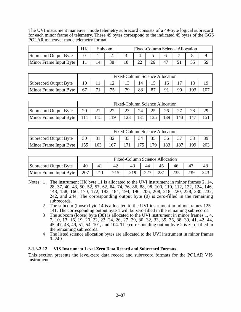
3–87
The UVI instrument maneuver mode telemetry subrecord consists of a 49-byte logical subrecordfor each minor frame of telemetry. These 49 bytes correspond to the indicated 49 bytes of the GGSPOLAR maneuver mode telemetry format.
HK Subcom Fixed-Column Science Allocation
Subrecord Output Byte 0 1 2 3 4 5 6 7 8 9
Minor Frame Input Byte 11 14 38 18 22 26 47 51 55 59
Fixed-Column Science Allocation
Subrecord Output Byte 10 11 12 13 14 15 16 17 18 19
Minor Frame Input Byte 67 71 75 79 83 87 91 99 103 107
Fixed-Column Science Allocation
Subrecord Output Byte 20 21 22 23 24 25 26 27 28 29
Minor Frame Input Byte 111 115 119 123 131 135 139 143 147 151
Fixed-Column Science Allocation
Subrecord Output Byte 30 31 32 33 34 35 36 37 38 39
Minor Frame Input Byte 155 163 167 171 175 179 183 187 199 203
Fixed-Column Science Allocation
Subrecord Output Byte 40 41 42 43 44 45 46 47 48
Minor Frame Input Byte 207 211 215 219 227 231 235 239 243
Notes: 1. The instrument HK byte 11 is allocated to the UVI instrument in minor frames 2, 14,28, 37, 40, 43, 50, 52, 57, 62, 64, 74, 76, 86, 88, 98, 100, 110, 112, 122, 124, 146,148, 158, 160, 170, 172, 182, 184, 194, 196, 206, 208, 218, 220, 228, 230, 232,242, and 244. The corresponding output byte (0) is zero-filled in the remainingsubrecords.
2. The subcom (loose) byte 14 is allocated to the UVI instrument in minor frames 125–141. The corresponding output byte 1 will be zero-filled in the remaining subrecords.
3. The subcom (loose) byte (38) is allocated to the UVI instrument in minor frames 1, 4,7, 10, 13, 16, 19, 20, 22, 23, 24, 26, 27, 29, 30, 32, 33, 35, 36, 38, 39, 41, 42, 44,45, 47, 48, 49, 51, 54, 101, and 104. The corresponding output byte 2 is zero-filled inthe remaining subrecords.
4. The listed science allocation bytes are allocated to the UVI instrument in minor frames0–249.
3.1.3.3.12 VIS Instrument Level-Zero Data Record and Subrecord Formats
This section presents the level-zero data record and subrecord formats for the POLAR VISinstrument.

3–88
3.1.3.3.12.1 VIS Instrument Science Telemetry Data Record and Subrecord Formats
The VIS instrument generates 54 bytes of telemetry in each POLAR minor frame during POLARscience telemetry mode. The following is the format of the level-zero-processed VIS data recordfor the POLAR science telemetry mode.
Item Description Length(bytes)
Record(bytes)
1 Data record header 300 0–299
2 Subrecord 1 containing VIS level-zero data from POLARminor frame 0
54 300–353
3 Subrecord 2 containing VIS level-zero data from POLARminor frame 1
54 354–407
4–250 Subrecord 3–249 containing VIS level-zero data fromPOLAR minor frames 2–248
13,338 408–13,745
251 Subrecord 250 containing VIS level-zero data fromPOLAR minor frame 249
54 13,746–13,799
Total record length: 13,800 bytes (3450 words)
The VIS instrument science telemetry subrecord format consists of a 54-byte logical subrecord foreach minor frame of telemetry. These 54 bytes correspond to the indicated 54 minor frame bytes ofthe GGS POLAR spacecraft telemetry format.
HK Subcom Fixed-Column Science Allocation
Subrecord Output Byte 0 1 2 3 4 5 6 7 8 9 10
Minor Frame Input Byte 11 12 13 16 24 25 27 29 35 45 46
Fixed-Column Science Allocation
Subrecord Output Byte 11 12 13 14 15 16 17 18 19 20
Minor Frame Input Byte 53 54 61 62 69 70 77 78 85 86
Fixed-Column Science Allocation
Subrecord Output Byte 21 22 23 24 25 26 27 28 29 30
Minor Frame Input Byte 101 102 109 110 117 118 125 126 133 134
Fixed-Column Science Allocation
Subrecord Output Byte 31 32 33 34 35 36 37 38 39 40
Minor Frame Input Byte 141 142 149 150 157 158 165 166 173 174

3–89
Fixed-Column Science Allocation
Subrecord Output Byte 41 42 43 44 45 46 47 48 49 50
Minor Frame Input Byte 181 182 189 190 236 237 238 240 241 242
Fixed-Column Science Allocation
Subrecord Output Byte 51 52 53
Minor Frame Input Byte 252 253 254
Notes: 1. The instrument HK byte 11 is allocated to the VIS instrument in minor frames 11, 12,25, 59, 60, 71, 72, 83, 84, 95, 96, 107, 108, 119, 120, 131, 132, 143, 144, 155,156, 167, 168, 179, 180, 191, 192, 203, 204, 215, 216, 227, 228, 239, and 240. TheHK byte 12 is allocated to the VIS instrument in minor frames 23, 35, and 47. Thecorresponding output bytes (0 and 1) will be zero-filled in the remaining records.
2. The subcom byte 13 is allocated to the VIS instrument in minor frames 0–141. Thecorresponding output byte 1 will be zero-filled in minor frames 142–249. The subcom(loose) byte 16 is allocated to the VIS instrument in minor frames 242–249. Thecorresponding output bytes (2 and 3) will be zero-filled in the remaining subrecords.
3. The listed science allocation bytes are allocated to the VIS instruments in minor frames0–249.
3.1.3.3.12.2 VIS Instrument Contingency Science Telemetry Data Record and SubrecordFormats
The VIS instrument generates 2 bytes of telemetry in each POLAR minor frame during POLARcontingency mode. The following is the format of the level-zero-processed VIS data record for thePOLAR contingency mode.
Item Description Length(bytes)
Record(bytes)
1 Data record header 300 0–299
2 Subrecord 1 containing UVI level-zero data from POLARminor frame 0
2 300–301
3 Subrecord 2 containing UVI level-zero data from POLARminor frame 1
2 302–303
4–250 Subrecord 3–249 containing UVI level-zero data fromPOLAR minor frames 2–248
494 304–797
251 Subrecord 250 containing UVI level-zero data fromPOLAR minor frame 249
2 798–799
252 Fill bytes to pad record out to 4-byte word boundary 1992 800–2791
Total record length: 2792 bytes (698 words)
The VIS instrument contingency science telemetry subrecord consists of a 2-byte logical subrecordcorresponding to the indicated bytes of the GGS POLAR instrument contingency subrecordformat.
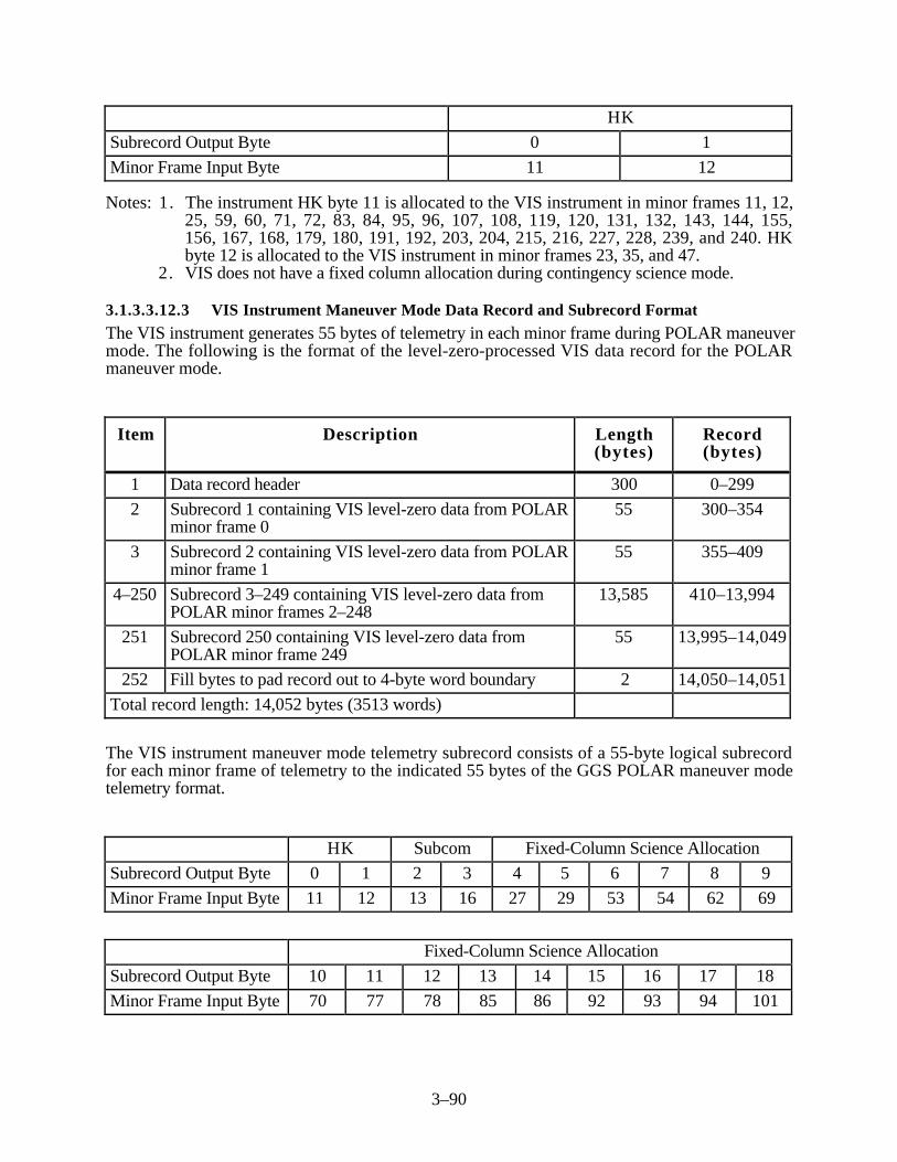
3–90
HK
Subrecord Output Byte 0 1
Minor Frame Input Byte 11 12
Notes: 1. The instrument HK byte 11 is allocated to the VIS instrument in minor frames 11, 12,25, 59, 60, 71, 72, 83, 84, 95, 96, 107, 108, 119, 120, 131, 132, 143, 144, 155,156, 167, 168, 179, 180, 191, 192, 203, 204, 215, 216, 227, 228, 239, and 240. HKbyte 12 is allocated to the VIS instrument in minor frames 23, 35, and 47.
2. VIS does not have a fixed column allocation during contingency science mode.
3.1.3.3.12.3 VIS Instrument Maneuver Mode Data Record and Subrecord Format
The VIS instrument generates 55 bytes of telemetry in each minor frame during POLAR maneuvermode. The following is the format of the level-zero-processed VIS data record for the POLARmaneuver mode.
Item Description Length(bytes)
Record(bytes)
1 Data record header 300 0–299
2 Subrecord 1 containing VIS level-zero data from POLARminor frame 0
55 300–354
3 Subrecord 2 containing VIS level-zero data from POLARminor frame 1
55 355–409
4–250 Subrecord 3–249 containing VIS level-zero data fromPOLAR minor frames 2–248
13,585 410–13,994
251 Subrecord 250 containing VIS level-zero data fromPOLAR minor frame 249
55 13,995–14,049
252 Fill bytes to pad record out to 4-byte word boundary 2 14,050–14,051
Total record length: 14,052 bytes (3513 words)
The VIS instrument maneuver mode telemetry subrecord consists of a 55-byte logical subrecordfor each minor frame of telemetry to the indicated 55 bytes of the GGS POLAR maneuver modetelemetry format.
HK Subcom Fixed-Column Science Allocation
Subrecord Output Byte 0 1 2 3 4 5 6 7 8 9
Minor Frame Input Byte 11 12 13 16 27 29 53 54 62 69
Fixed-Column Science Allocation
Subrecord Output Byte 10 11 12 13 14 15 16 17 18
Minor Frame Input Byte 70 77 78 85 86 92 93 94 101
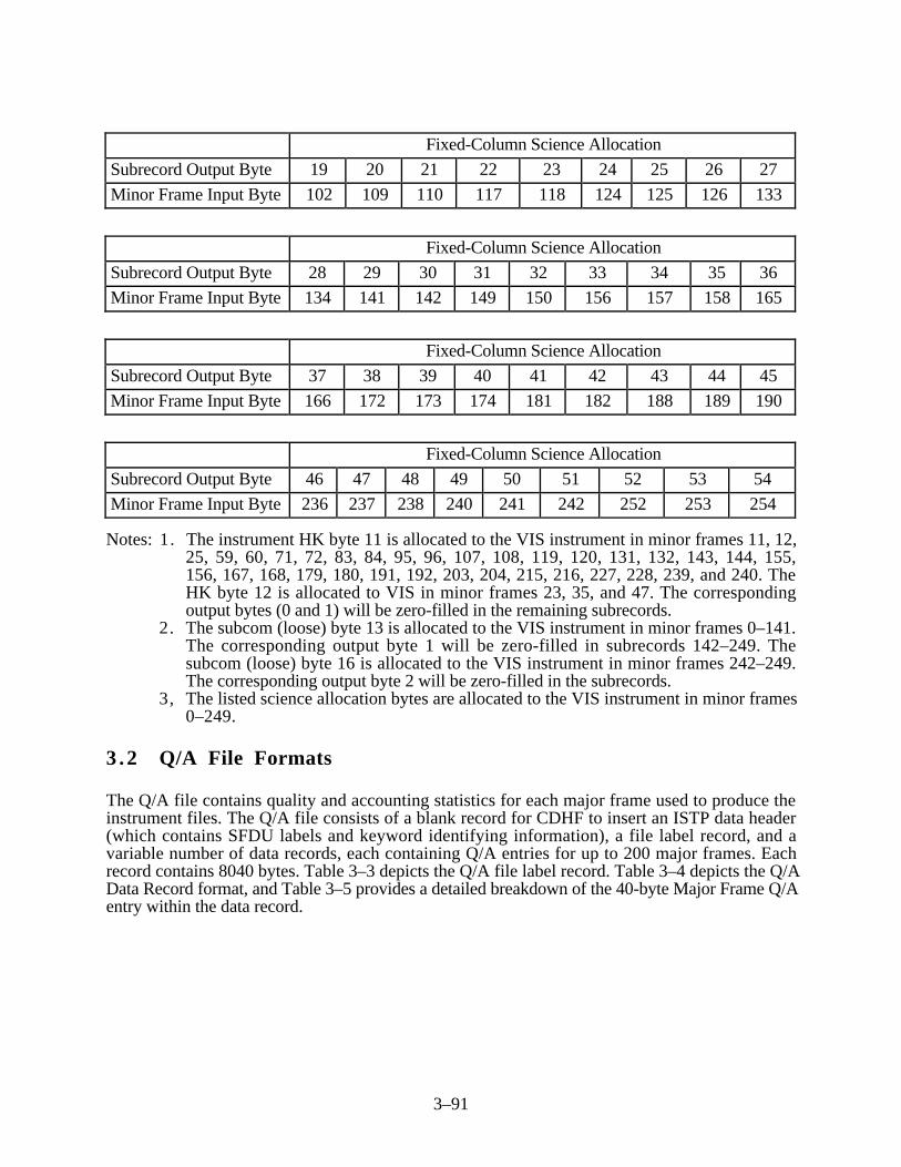
3–91
Fixed-Column Science Allocation
Subrecord Output Byte 19 20 21 22 23 24 25 26 27
Minor Frame Input Byte 102 109 110 117 118 124 125 126 133
Fixed-Column Science Allocation
Subrecord Output Byte 28 29 30 31 32 33 34 35 36
Minor Frame Input Byte 134 141 142 149 150 156 157 158 165
Fixed-Column Science Allocation
Subrecord Output Byte 37 38 39 40 41 42 43 44 45
Minor Frame Input Byte 166 172 173 174 181 182 188 189 190
Fixed-Column Science Allocation
Subrecord Output Byte 46 47 48 49 50 51 52 53 54
Minor Frame Input Byte 236 237 238 240 241 242 252 253 254
Notes: 1. The instrument HK byte 11 is allocated to the VIS instrument in minor frames 11, 12,25, 59, 60, 71, 72, 83, 84, 95, 96, 107, 108, 119, 120, 131, 132, 143, 144, 155,156, 167, 168, 179, 180, 191, 192, 203, 204, 215, 216, 227, 228, 239, and 240. TheHK byte 12 is allocated to VIS in minor frames 23, 35, and 47. The correspondingoutput bytes (0 and 1) will be zero-filled in the remaining subrecords.
2. The subcom (loose) byte 13 is allocated to the VIS instrument in minor frames 0–141.The corresponding output byte 1 will be zero-filled in subrecords 142–249. Thesubcom (loose) byte 16 is allocated to the VIS instrument in minor frames 242–249.The corresponding output byte 2 will be zero-filled in the subrecords.
3, The listed science allocation bytes are allocated to the VIS instrument in minor frames0–249.
3 .2 Q/A File Formats
The Q/A file contains quality and accounting statistics for each major frame used to produce theinstrument files. The Q/A file consists of a blank record for CDHF to insert an ISTP data header(which contains SFDU labels and keyword identifying information), a file label record, and avariable number of data records, each containing Q/A entries for up to 200 major frames. Eachrecord contains 8040 bytes. Table 3–3 depicts the Q/A file label record. Table 3–4 depicts the Q/AData Record format, and Table 3–5 provides a detailed breakdown of the 40-byte Major Frame Q/Aentry within the data record.

3–92
Table 3–3. Q/A Label Record Definition
Field Bytes Name Comments
1 0–3 Spacecraft ID
2 4–7 File ID ‘Q/A’
3 8–11 Number of Q/A data records
4 12–27 File process time
5 28–39 Time of first major frame
6 40–51 Time of last major frame
7 52–55 Production indicator ‘PROD’/’Q/L’
8 56–59 Decom sequence number
9 60–63 Total number of major frames
10 64–67 Total number of data gaps
11 68–71 Total number of perfect major frames
12 72–75 Total number of error-free major frames
13 76–79 Total number of major frames with errors
14 80–83 Experiment file flags Note 1
15 84–8039 Spares
Note: Experiment flags are set to indicate which experiments the operator requested for inclusionin this set.
The following items describe the Q/A Label Record Fields.
Field Name: Spacecraft IDType/Length: Integer/4Value(s): 24 = GEOTAIL
25 = WIND26 = POLAR
Description: This field identifies the satellite that transmitted the data containedin the associated level-zero files.
Field Name: File IDType/Length: Character/4Value(s): ‘Q/A’Description: This field identifies the type of data contained in this Decom Q/A
file.
Field Name: Number of Q/A Data RecordsType/Length: Integer/4

3–93
Description: This field identifies the number of physical Q/A data recordscontained in this Decom Q/A file.
Field Name: File Process TimeType/Length: Character/16Description: This field identifies the wall clock time (GMT) that this Decom Q/A
file was created. The time is in the following format:
YYYYDDDHHMMSSUUU, whereYYYY = 4-digit year identifierDDD = 3-digit day of yearHH = 2-digit hour of dayMM = 2-digit minute of hourSS = 2-digit second of minuteUUU = 3-digit millisecond of second
Field Name: Time of First Major Frame—File Start TimeType/Length: Integer/12Description: This field identifies the first major frame in the Decom Q/A
file and has the following format: 16-bit binary year, 16-bit binaryday count, 32-bit binary millisecond of day, and 32-bitmicroseconds. Note: microsecond of day = microseconds + 1000*millisecond of day.
Field Name: Time of Last Major Frame—File End TimeType/Length: Integer/12Description: This field identifies the ATC of the last major frame in the
Decom Q/A file and has the following format: 16-bit binaryyear, 16-bit binary day count, 32-bit binary millisecond of day,and 32-bit microseconds. Note: microsecond of day =microseconds + 1000* millisecond of day.
Field Name: Production IndicatorType/Length: Character/4Value(s): ‘PROD’ or ‘Q/L’Description: This identifies the type of production run requested; production
(PROD) or quicklook (Q/L).
Field Name: Decom Sequence NumberType/Length: Integer/4Value(s): Starts at 0 and increments by 1 each Decom rerun.Description: This field identifies the decom sequence number associated
with the level-zero files.
Field Name: Total Number of Major FramesType/Length: Integer/4Description: This field identifies the total number of major frames contained
in the associated level-zero files.

3–94
Field Name: Total Number of Data GapsType/Length: Integer/4Description: This field identifies the number of places in the Decom Q/A
file that have a gap of one or more consecutive major frames.
Field Name: Total Number of Perfect Major FramesType/Length: Integer/4Description: This field identifies the total number of major frames that
contain neither minor frames with errors nor fill minor framesin the associated level-zero files.
Field Name: Total Number of Error-Free Major FramesType/Length: Integer/4Description: This field identifies the total number of major frames that
contain no minor frames with frame sync errors or major orminor frame counter errors in the associated level-zero files.They will, however, contain fill minor frames.
Field Name: Total Number of Major Frames With ErrorsType/Length: Integer/4Description: This field identifies the total number of major frames
containing at least one minor frame with a minor and/or amajor frame counter error and/or a frame sync error in theassociated level-zero file. They may, however, also containfill minor frames.
Field Name: Experiment File FlagsType/Length: Integer/4Description: This field identifies the experiments that were requested for
processing by the Decom subsystem.
Field Name: SparesType/Length: Character/7956Description: This field identifies the spare bytes that fill out the remainder
of the Decom Q/A label record. The spare bytes are zero(null)-filled.
Table 3–4. Q/A Data Record Format (1 of 2)
Field Bytes Name Comments
1 0–3 Record count
2 4–7 Number of major frame Q/A entries 1–200
3 8–11 Count of Q/A entries with data gap flag set
4 12–15 Count of perfect major frame Q/A entries

3–95
Table 3–4. Q/A Data Record Format (2 of 2)
Field Bytes Name Comments
5 16–39 Spares
6 40–79 Major frame Q/A entry 1
205 8000–8039 Major frame Q/A entry 200
Table 3–5. Major Frame Q/A Entry Format
Field Bytes Name Comments
1 0–1 Time: year
2 2–3 Time: day of year
3 4–7 Time: milliseconds of day
4 8–11 Time: microseconds of milliseconds
5 12–13 ATC correction flag
6 14–15 Data gap flag
7 16–17 Spare
8 18–19 Telemetry mode
9 20–23 Major frame counter
10 24–27 Number of fill minor frames
11 28–31 Number of minor frame counter errors
12 32–35 Number of frame sync pattern errors
13 36–39 Number of minor frame counter jumps
Note: The data gap flag is set to indicate a data gap of one or more major frames precedes themajor frame corresponding to this entry.
Field Name: Record CountType/Length: Integer/4Description: The relative position of this physical Q/A data record from
within the Q/A file.
Field Name: Number of Major Frame Q/A Entries in This RecordType/Length: Integer/4Description: The number of the logical decom Q/A entries contained in this
data record. The maximum number is 200.

3–96
Field Name: Count of Q/A Entries With the Data Gap Flag SetType/Length: Integer/4Description: The number of Q/A entries contained in this data record that
have the data gap flag set.
Field Name: Count of Perfect Major Frame Q/A EntriesType/Length: Integer/4Description: The number of Q/A entries contained in this data record that
have perfect major frames.
Field Name: SparesType/Length: Character/24Description: This field contains zero (null)-filled spare bytes.
The following 13 fields constitute one logical Decom Q/A entry. There may be 200 of these logicalDecom Q/A entries within each physical Q/A data record. A logical Decom Q/A entry spans 40bytes.
Field Name: Time: Year of the Major FrameType/Length: Integer/2 (16 bits)Description: The corrected year for the absolute time code associated with
this Q/A data entry.
Field Name: Time: Day of YearType/Length: Integer/2 (16 bits)Description: The corrected day for the absolute time code associated with
this Q/A data entry.
Field Name: Time: Milliseconds of DayType/Length: Integer/4Description: The corrected millisecond of day for the absolute time code
associated with this Q/A data entry.
Field Name: Time: MicrosecondsType/Length: Integer/4Description: The corrected microseconds for the absolute time code
associated with this Q/A data entry. (Note that microsecondsof day = microseconds + 1000* milliseconds of day.)
Field Name: ATC Correction FlagType/Length: Integer/2Description: This field is used to indicate whether the ATC time was
corrected. A value of one indicates that correction occurredand a value of zero indicates that correction did not occur.

3–97
Field Name: Data Gap FlagType/Length: Integer/2 (16 bits)Description: This field is used to indicate a data gap of one or more major
frames precedes this Q/A data entry. A value of one indicates adata gap has occurred and a value of zero indicates that a datagap did not occur.
Field Name: SpareType/Length: Integer/2 (16 bits)Description: This field contains zero (null)-filled spare bytes.
Field Name: Telemetry Mode IndicatorType/Length: Integer/2 (16 bits)Description: This field indicates the spacecraft’s mode during the major
frame.
Field Name: Major Frame CounterType/Length: Integer/4Description: This field specifies the major frame counter value for the
major frame associated with this Q/A data entry.
Field Name: Number of Fill Minor FramesType/Length: Integer/4Description: The number of minor frames contained in the major frame for
this Q/A data entry that were zero-filled by the edit process.
Field Name: Number of Minor Frame Counter ErrorsType/Length: Integer/4Description: The number of minor frames contained in the major frame for
the Q/A data entry that have minor frame counter errors.
Field Name: Number of Frame Sync Pattern ErrorsType/Length: Integer/4Description: The number of minor frames within the major frame for this
Q/A data entry that have frame sync pattern errors.
Field Name: Number of Minor Counter JumpsType/Length: Integer/4Description: The number of minor frames contained in the major frame for
the Q/A data entry that have minor frame counter jumps.
3 .3 Housekeeping Data Format
Spacecraft housekeeping data is level-zero data that provides health and safety information aboutthe spacecraft. A housekeeping data file contains the housekeeping data for one spacecraft(GEOTAIL, WIND, or POLAR) for a given day (midnight-to-midnight GMT).
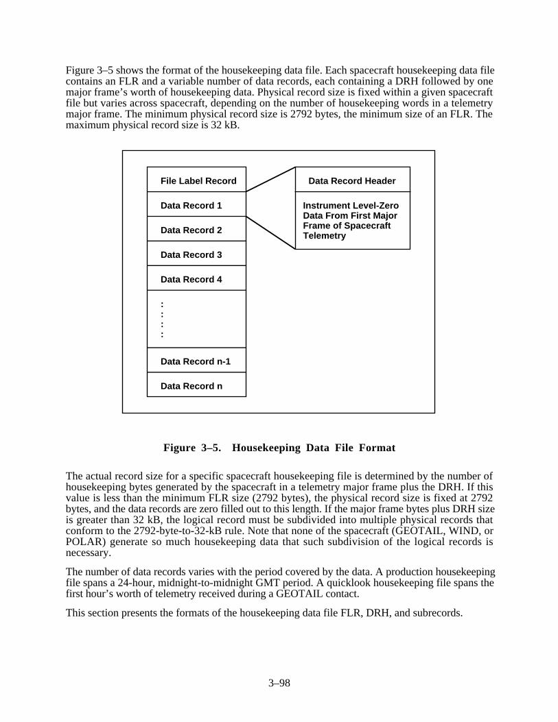
3–98
Figure 3–5 shows the format of the housekeeping data file. Each spacecraft housekeeping data filecontains an FLR and a variable number of data records, each containing a DRH followed by onemajor frame’s worth of housekeeping data. Physical record size is fixed within a given spacecraftfile but varies across spacecraft, depending on the number of housekeeping words in a telemetrymajor frame. The minimum physical record size is 2792 bytes, the minimum size of an FLR. Themaximum physical record size is 32 kB.
File Label Record
Data Record 1
Data Record 2
Data Record 4
Data Record 3
Data Record n-1
Data Record n
::::
Data Record Header
Instrument Level-Zero Data From First Major Frame of Spacecraft Telemetry
Figure 3–5. Housekeeping Data File Format
The actual record size for a specific spacecraft housekeeping file is determined by the number ofhousekeeping bytes generated by the spacecraft in a telemetry major frame plus the DRH. If thisvalue is less than the minimum FLR size (2792 bytes), the physical record size is fixed at 2792bytes, and the data records are zero filled out to this length. If the major frame bytes plus DRH sizeis greater than 32 kB, the logical record must be subdivided into multiple physical records thatconform to the 2792-byte-to-32-kB rule. Note that none of the spacecraft (GEOTAIL, WIND, orPOLAR) generate so much housekeeping data that such subdivision of the logical records isnecessary.
The number of data records varies with the period covered by the data. A production housekeepingfile spans a 24-hour, midnight-to-midnight GMT period. A quicklook housekeeping file spans thefirst hour’s worth of telemetry received during a GEOTAIL contact.
This section presents the formats of the housekeeping data file FLR, DRH, and subrecords.

3–99
3 . 3 . 1 Housekeeping Data File Label Record
An FLR is the first spacecraft housekeeping file record. The FLR occupies a minimum of 2792bytes. Table 3–1 defines each FLR field. The associated material in Section 3.1.1.2 describes eachFLR field. Note that the FLR for housekeeping data files is identical to the FLR for level-zero datafiles.
3 . 3 . 2 Housekeeping Data Subrecord Formats
Each data record in a housekeeping data file begins with a DRH. Note that the minor frame qualityfield (last field) consists of one byte of quality flags for each minor frame. This section defines anddescribes the DRH. Table 3–2 and its associated descriptive material define and describe each DRHfield. The DRH for a housekeeping data file is identical to the DRH for a level-zero data file.
3 . 3 . 3 Housekeeping Data Record and Subrecord Formats
The data (nonheader) part of each level-zero-processed data record for a given instrument issubdivided into fixed-length subrecords, each containing that instrument’s instrument data andinstrument housekeeping data from a minor, sometimes called sub, frame. The length of thesubrecord depends on the number of minor frame bytes allocated to spacecraft housekeeping.
The total length of the housekeeping record in bytes is the number of spacecraft housekeepingbytes per subrecord times the number of minor frames per major frame plus the DRH length plusany additional bytes needed to pad the record to the 4-byte word boundary. As indicated in Section3.3, the minimum data record size is 2792 bytes, the minimum size of an FLR. Note that forWIND/POLAR instruments, the DRH is 300 bytes long and there are 250 minor frames per majorframe. For GEOTAIL, the DRH is 560 bytes long and there are 512 minor frames per majorframe.
A zero-filled (null) subrecord is put in the output data record when the associated input minorframe is missing or cannot be interpreted. The DRH contains 1 byte of quality flags for each minorframe (subrecord). One quality flag indicates whether the associated subrecord is filled with zeros.Other quality flags denote frame counter and frame synchronization errors. The statisticalinformation in the Q/A file record associated with a major frame also indicates which minor frames(subrecords) are zero-filled.
The ISTP GDPS never outputs an entire major frame of zero fill. Thus, if the entire major frame ismissing from the input or is uninterpretable, the result will be a time gap in the output. The Q/A fileindicates which major frames are missing. A missing major frame also can be determined bycomparing the major frame count in the DRH of the previous data record to that of the current datarecord. The frame count increases monotonically from one record to the next when there is no gapbetween them.
Each housekeeping subrecord is presented as a horizontal table containing Subrecord Output Byte0 through the last byte in the subrecord. Multiple rows are used as necessary. Immediately beloweach row of Subrecord Output Bytes is a row depicting the corresponding minor frame input bytethat is the data source for the output byte. Commentary notes are used when necessary to describean unusual circumstance.
As applicable, multiple formats are shown for spacecraft to depict normal mode and maneuvermode formats.
NRT housekeeping data for WIND and POLAR is generated on the CDHF, but not distributed tothe DDF. The format of the NRT housekeeping data is identical to the format of the production

3–100
housekeeping data originating from the GDCF. Because of the NRT system operation, the recordsize for each mission’s NRT housekeeping data is set to the largest record size possible for themission. For example, if the production WIND housekeeping data record size is 4,052 bytesduring science telemetry mode and 17,300 bytes during maneuver telemetry mode, the record sizefor WIND NRT housekeeping data is always 17,300 bytes (the larger of the two record sizes). Incases where the NRT record size for the current telemetry mode is less than the maximum, theremaining bytes in the record are zero-filled.
The formats of the housekeeping data subrecords for the GEOTAIL, WIND, and POLARspacecraft are presented in the following subsections.
3.3.3.1 GEOTAIL Spacecraft Housekeeping Data Record and Subrecord Formats
This section presents the housekeeping data records and subrecord formats for the GEOTAILspacecraft. The GEOTAIL spacecraft generates 11 bytes of housekeeping telemetry in eachGEOTAIL minor frame during the GEOTAIL record observation (normal) and contingency modes.The following is the format of the level-zero-processed housekeeping data record for theGEOTAIL record observation and contingency modes.
Item Description Length(bytes)
Record(bytes)
1 Data record header 560 0–559
2 Subrecord 1 containing spacecraft housekeeping data fromGEOTAIL minor frame 0
11 560–570
3 Subrecord 2 containing spacecraft housekeeping data fromGEOTAIL minor frame 1
11 571–581
4–512 Subrecord 3–511 containing spacecraft housekeeping datafrom GEOTAIL minor frames 2–510
5599 582–6180
513 Subrecord 512 containing spacecraft housekeeping datafrom GEOTAIL minor frame 511
11 6181–6191
Total record length: 6192 bytes (1548 words)
The GEOTAIL spacecraft housekeeping record observation mode and contingency mode subrecordformat consists of an 11-byte logical subrecord for each minor frame in a major frame of telemetry.These 11 bytes correspond to the indicated 11 minor frame bytes of the GEOTAIL spacecraftrecord observation or contingency telemetry format.
Subrecord Output Byte 0 1 2 3 4 5 6 7 8 9 10
Minor Frame Input Byte 5 6 7 8 9 10 11 12 13 14 15
3.3.3.2 WIND Spacecraft Housekeeping Data Record and Subrecord Formats
This section presents the housekeeping data record and subrecord formats for the WINDspacecraft. The formats for two WIND telemetry modes are provided: science telemetry andmaneuver. Note that the maneuver mode record size applies for the entire day (midnight tomidnight) of a maneuver.

3–101
3.3.3.2.1 WIND Science Mode Housekeeping Data Record and Subrecord Formats
The WIND spacecraft instrument generates 13 bytes of telemetry in each WIND minor frameduring WIND science telemetry mode. In addition, the housekeeping record includes 2 bytes ofinstrument housekeeping data. Thus, the record contains 15 bytes. The following is the format ofthe level-zero-processed spacecraft housekeeping data record for the WIND science telemetrymode.
Note that the details regarding which minor frames of the instrument housekeeping bytes areallocated to a specific WIND instrument are provided in the subsections of Section 3.1.3.2, WINDSpacecraft Level-Zero Data Record and Subrecord Formats.
Item Description Length(bytes)
Record(bytes)
1 Data record header 300 0–299
2 Subrecord 1 containing spacecraft housekeeping data fromWIND minor frame 0
15 300–314
3 Subrecord 2 containing spacecraft housekeeping data fromWIND minor frame 1
15 315–329
4–250 Subrecord 3–249 containing spacecraft housekeeping datafrom WIND minor frames 2–248
3705 330–4034
251 Subrecord 250 containing spacecraft housekeeping datafrom WIND minor frame 249
15 4035–4049
252 Zero (null) bytes to pad record out to 4-byte wordboundary
2 4050–4051
Total record length: 4052 bytes (1013 words)
The WIND spacecraft science telemetry mode housekeeping format consists of a 15-byte logicalsubrecord for each minor frame of input telemetry. These 15 bytes correspond to the indicated15 minor frame bytes of the GGS WIND spacecraft telemetry format.
C&DH Status ACADS S/C HK Inst.HK
Subrecord Output Byte 0 1 2 3 4 5 6 7 8 9 10 11 12 13 14
Minor Frame Input Byte 4 5 6 7 8 9 10 11 12 13 14 15 16 17 18
3.3.3.2.2 WIND Maneuver Mode Housekeeping Data Record and Subrecord Formats
The WIND spacecraft generates 64 bytes of housekeeping telemetry in each WIND minor frameduring WIND maneuver mode. In addition, the housekeeping record includes 2 bytes ofinstrument housekeeping data. Thus, the record contains 66 bytes. The following is the format ofthe level-zero-processed spacecraft housekeeping data record for the WIND maneuver mode.
Note that the details regarding which minor frames of the instrument housekeeping bytes areallocated to a specific WIND instrument are provided in the subsections of Section 3.1.3.2, WINDSpacecraft Level-Zero Data Record and Subrecord Formats.
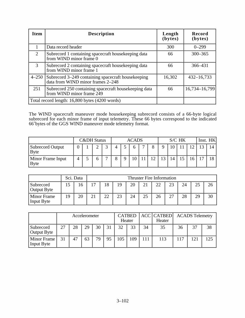
3–102
Item Description Length(bytes)
Record(bytes)
1 Data record header 300 0–299
2 Subrecord 1 containing spacecraft housekeeping datafrom WIND minor frame 0
66 300–365
3 Subrecord 2 containing spacecraft housekeeping datafrom WIND minor frame 1
66 366–431
4–250 Subrecord 3–249 containing spacecraft housekeepingdata from WIND minor frames 2–248
16,302 432–16,733
251 Subrecord 250 containing spacecraft housekeeping datafrom WIND minor frame 249
66 16,734–16,799
Total record length: 16,800 bytes (4200 words)
The WIND spacecraft maneuver mode housekeeping subrecord consists of a 66-byte logicalsubrecord for each minor frame of input telemetry. These 66 bytes correspond to the indicated66 bytes of the GGS WIND maneuver mode telemetry format.
C&DH Status ACADS S/C HK Inst. HK
Subrecord OutputByte
0 1 2 3 4 5 6 7 8 9 10 11 12 13 14
Minor Frame InputByte
4 5 6 7 8 9 10 11 12 13 14 15 16 17 18
Sci. Data Thruster Fire Information
SubrecordOutput Byte
15 16 17 18 19 20 21 22 23 24 25 26
Minor FrameInput Byte
19 20 21 22 23 24 25 26 27 28 29 30
Accelerometer CATBEDHeater
ACC CATBEDHeater
ACADS Telemetry
SubrecordOutput Byte
27 28 29 30 31 32 33 34 35 36 37 38
Minor FrameInput Byte
31 47 63 79 95 105 109 111 113 117 121 125

3–103
ACC ACADS Telemetry RCS ACC RCS Power ACC
Subrecord OutputByte
37 38 39 40 41 42 43 44 45 46 47
Minor Frame InputByte
127 129 133 137 141 143 145 149 153 157 159
LANYARDBoom Data
CAT-BED
Heater
LANYARD Boom
Data
CATBEDHeater
Accel. CAT-BED
Heater
PowerComm
SubrecordOutput Byte
48 49 50 51 52 53 54 55 56 57
Minor FrameInput Byte
161 165 166 169 170 173 174 175 177 178
Power PowerComm
Accelerometer
Subrecord Output Byte 58 59 60 61 62 63 64 65
Minor Frame Input Byte 181 185 189 191 207 223 239 255
3.3.3.3 POLAR Spacecraft Housekeeping Data Record and Subrecord Formats
This section presents the housekeeping data record and subrecord formats for the POLARspacecraft. Formats are provided for three telemetry modes: science telemetry, contingency, andmaneuver. Note that the record size for maneuver mode applies for the entire day of a maneuver.
3.3.3.3.1 POLAR Science and Contingency Modes Housekeeping Data Record and SubrecordFormats
The POLAR spacecraft generates 7 bytes of housekeeping telemetry in each POLAR minor frameduring both science telemetry and contingency modes. In addition, the housekeeping recordincludes 2 bytes of instrument housekeeping data. Thus, the record contains 9 bytes. Thefollowing is the format of the level-zero-processed spacecraft housekeeping data record for bothmodes.
Note that the details regarding which minor frames of the instrument housekeeping bytes areallocated to a specific POLAR instrument are provided in the subsections of Section 3.1.3.3,POLAR Spacecraft Level-Zero Data Record and Subrecord Formats.
Item Description Length(bytes)
Record(bytes)
1 Data record header 300 0–299
2 Subrecord 1 containing spacecraft housekeeping datafrom POLAR minor frame 0
9 300–308

3–104
Item Description Length(bytes)
Record(bytes)
3 Subrecord 2 containing spacecraft housekeeping datafrom POLAR minor frame 1
9 309–317
4–250 Subrecord 3–249 containing spacecraft housekeepingdata from POLAR minor frames 2–248
2,223 318–2540
251 Subrecord 250 containing spacecraft housekeeping datafrom POLAR minor frame 249
9 2541–2549
252 Zero (null) fill bytes to pad out to minimum record length 242 2550–2791
Total record length: 2792 bytes (698 words)
The POLAR spacecraft science telemetry housekeeping subrecord format consists of a 9-bytelogical subrecord for each minor frame of telemetry. These 9 bytes correspond to the indicated 9minor frame bytes of the GGS POLAR spacecraft telemetry format.
C&DHStatus
ACADS/DPM
Software
UplinkStatus
S/C HK Inst. HK
Subrecord Output Byte 0 1 2 3 4 5 6 7 8
Minor Frame Input Byte 4 5 6 7 8 9 10 11 12
Note: The POLAR MFE magnetometer (mag) data can be retrieved from the instrument HK asfollows:
• MNTSCALE (8-bit binary integer used for scaling the vectors) in minor frame inputbyte 12, minor frame 63
• BX (16-bit, two’s complement uncalibrated integer vector component) in minor frameinput bytes 11 and 12, minor frame 87
• BY (16-bit, two’s complement uncalibrated integer vector component) in minor frameinput bytes 11 and 12, minor frame 99
• BZ (16-bit, two’s complement uncalibrated integer vector component) in minor frameinput bytes 11 and 12, minor frame 111
To access the MFE magnetometer data from the POLAR spacecraft housekeeping file, a userwould call the ICSS routine to read in the spacecraft housekeeping file. The user would then usehis/her code for extracting the MFE magnetometer data. An example of such a code is given inFigure 3–6.
The magnitude range of the raw BX, BY, BZ values could extend to ±32767 data numbers (dn)depending on the instrument setup (sensor and scale factor). Under normal operations, the goal isto maintain less than full-scale values (i.e., ±25000 dn).
To compute the B components in nanoteslas (nT), the following operations are performed usingfloating-point arithmetic:
• Bxcal = Bx av/(Cnts/nT)• Bycal = By av/(Cnts/nT)• Bzcal = Bz av/(Cnts/nT)

3–105
c
c Example Code for Extracting MFE Data
c From the POLAR SPACECRAFT Housekeeping Data
c
subroutine get_polar_mag_data (major_frame, mntscale, bx, by, bz)
byte major_frame (*) ! Buffer containing major frame
integer*4 mntscale ! Magnetometer scale factor
integer*4 bx, by, bz ! Magnetometer vector
integer*4 frame_no, ! Minor frame number
. index, ! Index into major frame buffer
. frame_size / 9 / , ! Minor frame size
. iword ! Equivalenced variable used to
! transfer bytes to vector
byte bword (4) ! Equivalenced array
equivalence (iword, bword(1))
c
c Get the MNTSCALE value out of byte 7 (array index 8) of minor frame 63
c
frame_no = 63
index = 300 + (frame_no * frame_size) + 8
bword(1) = major_frame (index)
bword(2) = 0
mntscale = iword
c
c Get the BX value out of bytes 7 and 8 of minor frame 87
c
frame_no = 87
index = 300 + (frame_no * frame_size) + 8
bword(2) = major_frame (index)
bword(1) = major_frame (index+1)
bx = iword
c
Figure 3–6. Code To Extract MFE Magnetometer Data From POLARHousekeeping Data File (1 of 2)
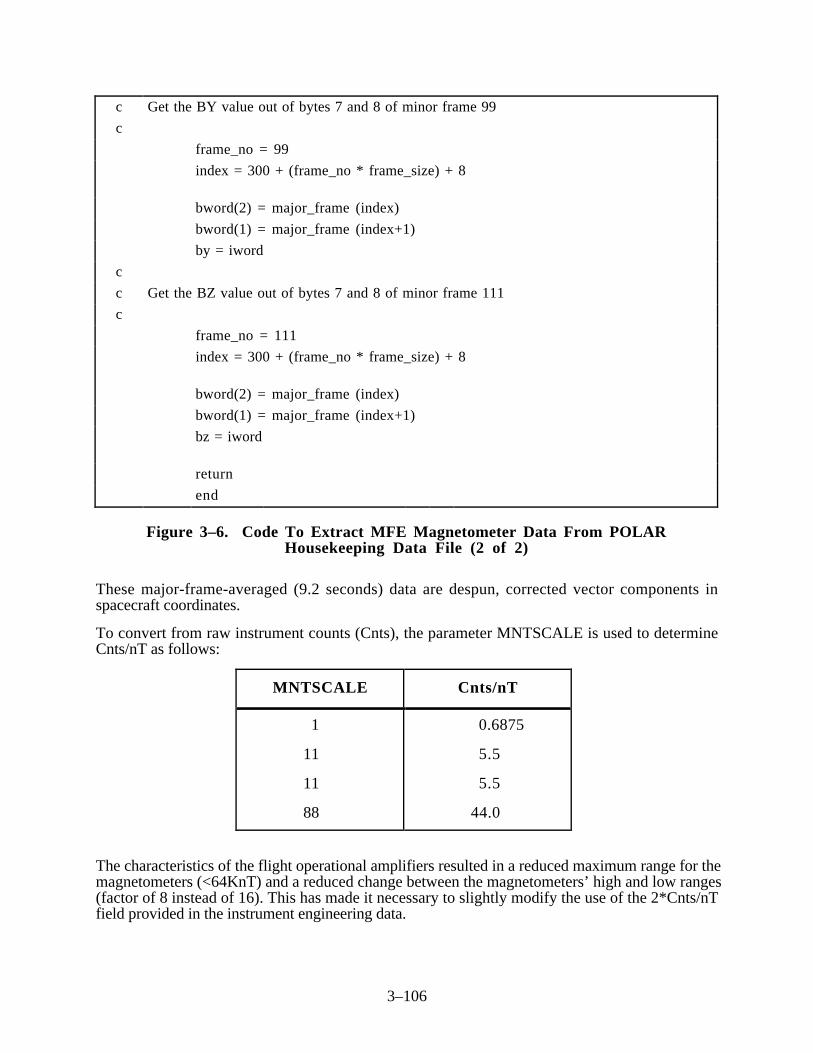
3–106
c Get the BY value out of bytes 7 and 8 of minor frame 99
c
frame_no = 99
index = 300 + (frame_no * frame_size) + 8
bword(2) = major_frame (index)
bword(1) = major_frame (index+1)
by = iword
c
c Get the BZ value out of bytes 7 and 8 of minor frame 111
c
frame_no = 111
index = 300 + (frame_no * frame_size) + 8
bword(2) = major_frame (index)
bword(1) = major_frame (index+1)
bz = iword
return
end
Figure 3–6. Code To Extract MFE Magnetometer Data From POLARHousekeeping Data File (2 of 2)
These major-frame-averaged (9.2 seconds) data are despun, corrected vector components inspacecraft coordinates.
To convert from raw instrument counts (Cnts), the parameter MNTSCALE is used to determineCnts/nT as follows:
MNTSCALE Cnts/nT
1
11
11
88
0.6875
5.5
5.5
44.0
The characteristics of the flight operational amplifiers resulted in a reduced maximum range for themagnetometers (<64KnT) and a reduced change between the magnetometers’ high and low ranges(factor of 8 instead of 16). This has made it necessary to slightly modify the use of the 2*Cnts/nTfield provided in the instrument engineering data.

3–107
The following table presents the values used:
Inst ModeSens-Range
Engr Word2*Cnts/nT
(MNTSCALE)Actual Cnts/nT Full-Scale Field
(32768 Cnts)
IN-HI
IN-LO
OUT-HI
OUT-LO
1
11
11
88
0.6875
5.5
5.5
44.0
47662.5nT
5957.82
5957.82
744.727
The Cnts/nT are prelaunch values that could change during on-orbit operations. Therefore, tofacilitate updating these values, the KPGS should access them from a parameter file.
3.3.3.3.2 POLAR Spacecraft Maneuver Mode Housekeeping Data Record and SubrecordFormats
The POLAR spacecraft generates 50 bytes of spacecraft housekeeping telemetry in each POLARminor frame during POLAR maneuver mode. In addition, the housekeeping record contains2 bytes of instrument housekeeping data. Thus, the housekeeping records contain 52 bytes. Thefollowing is the format of the level-zero-processed POLAR data record for the POLAR maneuvermode.
Note that the details regarding which minor frames of the instrument housekeeping bytes areallocated to a specific POLAR instrument are provided in the subsections of Section 3.1.3.3,POLAR Spacecraft Level-Zero Data Record and Subrecord Formats.
Item Description Length(bytes)
Record(bytes)
1 Data record header 300 0–299
2 Subrecord 1 containing spacecraft housekeeping datafrom POLAR minor frame 0
52 300–351
3 Subrecord 2 containing spacecraft housekeeping datafrom POLAR minor frame 1
52 352–403
4–250 Subrecord 3–249 containing spacecraft housekeepingdata from POLAR minor frames 2–248
12,844 404–13,247
251 Subrecord 250 containing spacecraft housekeeping datafrom POLAR minor frame 249
52 13,248–13,299
Total record length: 13,300 bytes (3325 words)
The POLAR spacecraft maneuver mode housekeeping subrecord format consists of a 52-bytelogical subrecord corresponding to the indicated 52 bytes of the GGS POLAR maneuver modescience telemetry format.

3–108
C&DHStatus
ACADS/DPM
UplinkStatus
S/C HK Inst. HK DPM
Subrecord OutputByte
0 1 2 3 4 5 6 7 8 9 10 11
Minor Frame InputByte
4 5 6 7 8 9 10 11 12 20 24 25
DPM ACC DPMS/C
Telem-etry
Subrecord Output Byte 12 13 14 15 16 17 18 19 20 21 22
Minor Frame Input Byte 28 31 34 35 36 42 43 44 45 46 52
S/CTelemetry
ACC S/C Telemetry ACC S/CTelemetry
ACADSFSW
Subrecord Output Byte 23 24 25 26 27 28 29 30 31 32
Minor Frame Input Byte 60 61 63 68 76 84 95 100 108 116
ACC S/C Telemetry ACC S/C Telemetry
Subrecord Output Byte 33 34 35 36 37 38 39 40 41
Minor Frame Input Byte 127 132 140 145 146 148 159 164 180
ACC S/C Telemetry ACC S/C Telemetry ACC
Subrecord Output Byte 42 43 44 45 46 47 48 49 50 51
Minor Frame Input Byte 191 196 197 198 223 247 248 250 251 255
3 .4 SIRIUS Data Format
This section describes the SIRIUS data format for nondecommutated telemetry data for theGEOTAIL mission. SIRIUS data is nondecommutated, quality checked, time-ordered telemetry inthe format utilized by ISAS. During GEOTAIL’s normal mode, the SIRIUS data for a day(24 hours, midnight-to-midnight GMT) is divided into four files. Each file covers approximately6 hours and contains the telemetry for an integral number of major frames.
During GEOTAIL’s high-rate (65 kbps) contingency mode, necessitated by a GEOTAIL spacecrafteditor failure, the SIRIUS data for a day is divided into files covering a maximum of 1-1/2 hourseach. This is a maximum of 16 files per day, but the coverage may not include the entire day(because of data gaps). Thus, there may be fewer than 16 files.
Figure 3–7 depicts the high-level format of a SIRIUS data file. A record in a SIRIUS data filecontains 144 bytes. The records are placed in blocks of 160 records (23040 bytes) each. As shownin Figure 3–7, a SIRIUS data file has three parts: message data, telemetry data, and control block.The message data part occupies the first 20 records (2880 bytes) of the first 23040-byte block.(The remainder of this block is used for telemetry.) The detailed format of the message data portionis presented in Figure 3–8.

3–109
Message Data Telemetry Data Control Block
2880 bytes
(20 records at144 bytes/record)
144 bytes/minor frame x N Records
[N = approximate number of telemetry records(minor frames) in 6 hours (normal mode,1-1/2 hours for contingency mode)]
160 records/block
23040 bytes
(160 records at144 bytes/record)
Note that the first block contains the message data (2880 bytes) followed by the first 140 records(20,160 bytes) of telemetry data.
Figure 3–7. SIRIUS Data Format for Telemetry Playback Data
BYTE NO. BYTE LENGTH MESSAGE DATA
1371721272931
24
104622
20
X “FFFF”SATELLITE CODE (GEOTAIL:0023)PATH NUMBER. YYMMDD9999BLANKNUMBER OF FRAMESSTATION IDDATA IDDATA NAME: EX. “GEOTAIL JKSC PLAYBACK DATA”
51 30 FIRST FRAME DATE:YYMMDDTIME:HHMMSSss0FI COUNTERTI COUNTERBLANK
(6C)(9C)(1C)(3C)(10C)(1C)
C:CHARACTERminor frame count
81 30 LAST FRAME DATE:YYMMDDTIME:HHMMSSss0FI COUNTERTI COUNTERBLANK
(6C)(9C)(1C)(3C)(10C)(1C)
C:CHARACTER32-bit time code
111 30 TIME CORRELATIONDATA
DATE:YYMMDDTIME:HHMMSSss0FI COUNTERTI COUNTERBLANK
(6C)(9C)(1C)(3C)(10C)(1C)
C:CHARACTER
141145153289433577
721
48
136144144144
2160
BLANKTI INTERVALBLANKCOMMENTBLANKMESSAGE DATA(RAW DATA)BLANK
4C(MILLISECOND)
Figure 3–8. Message Data Part of SIRIUS Data File
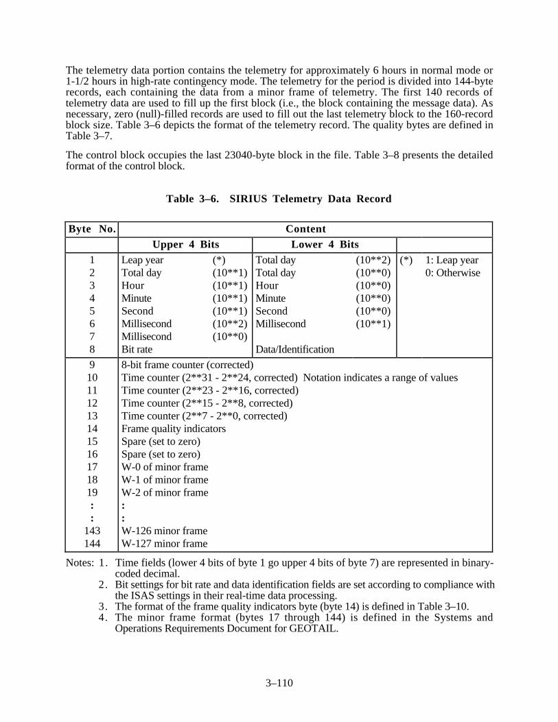
3–110
The telemetry data portion contains the telemetry for approximately 6 hours in normal mode or1-1/2 hours in high-rate contingency mode. The telemetry for the period is divided into 144-byterecords, each containing the data from a minor frame of telemetry. The first 140 records oftelemetry data are used to fill up the first block (i.e., the block containing the message data). Asnecessary, zero (null)-filled records are used to fill out the last telemetry block to the 160-recordblock size. Table 3–6 depicts the format of the telemetry record. The quality bytes are defined inTable 3–7.
The control block occupies the last 23040-byte block in the file. Table 3–8 presents the detailedformat of the control block.
Table 3–6. SIRIUS Telemetry Data Record
Byte No. ContentUpper 4 Bits Lower 4 Bits
12345678
Leap yearTotal dayHourMinuteSecondMillisecondMillisecondBit rate
(*)(10**1)(10**1)(10**1)(10**1)(10**2)(10**0)
Total dayTotal dayHourMinuteSecondMillisecond
Data/Identification
(10**2)(10**0)(10**0)(10**0)(10**0)(10**1)
(*) 1: Leap year0: Otherwise
910111213141516171819::
143144
8-bit frame counter (corrected)Time counter (2**31 - 2**24, corrected) Notation indicates a range of valuesTime counter (2**23 - 2**16, corrected)Time counter (2**15 - 2**8, corrected)Time counter (2**7 - 2**0, corrected)Frame quality indicatorsSpare (set to zero)Spare (set to zero)W-0 of minor frameW-1 of minor frameW-2 of minor frame::W-126 minor frameW-127 minor frame
Notes: 1. Time fields (lower 4 bits of byte 1 go upper 4 bits of byte 7) are represented in binary-coded decimal.
2. Bit settings for bit rate and data identification fields are set according to compliance withthe ISAS settings in their real-time data processing.
3. The format of the frame quality indicators byte (byte 14) is defined in Table 3–10.4. The minor frame format (bytes 17 through 144) is defined in the Systems and
Operations Requirements Document for GEOTAIL.

3–111
Table 3–7. GEOTAIL Frame Quality Indicators Format
Bit Number Content0
(MSB)Always 0
1 Always 0
2 Frame counter correction
This quality flag is set to a 1 if a fill minor frame (containing all zeros) wasinserted in the dataset to replace a minor frame which could not be placed in timeorder during level-zero processing because of errors in the fields.
3 Always 0
4 Frame sync error detected
This quality flag is set to a 1 if one or more bit errors in the frame sync patternwere detected for this particular minor frame.
5 Always 0
6
7(LSB)
Spare (set to 0)
Notes: 1. MSB is most significant bit; LSB is least significant byte.2. These frame quality indicators are set to zero for now as specified by ISAS.
Table 3–8. Control Block for SIRIUS Data
Byte No. Lengthin Bytes
Name/Short Description
1 2 Message data pattern, X “FEFE”
3 2 Number of data blocks (16-bit binary)
5 4 Spacecraft clock reading at first frame in first block (32-bit timecount)
9 4 Block address of first block (number of the block within the file)(32-bit binary)
13 4 Spacecraft clock reading at first frame in second block
17 4 Block address of second block
::
::
::
4 Spacecraft clock reading at first frame in nth block
4 Block address of nth block
Null bytes to fill the block to the 23,040-byte block size
Total block size = 23,040 bytes

3–112
MESSAGE DATA DESCRIPTION
Note that the character code used is Extended Binary-Coded Decimal Interchange Code (EBCDIC).
Field Name: Message Data PatternType/Length: X*2Definition: Fixed pattern to identify beginning of message data portion of file.Value(s): X “FFFF”
Field Name: Satellite CodeType/Length: C*4Definition: Identifies the spacecraftValue(s): “0023” for GEOTAIL
Field Name: File (Path) NumberType/Length: C*10Definition: The file identifier in the form YYMMDDXXXX where YY is the
2-digit year, MM is the 2-digit month, and XXXX identifies whichof the sixteen files for the day.
Value(s): For XXXX“0000” First file“0100” Second file“0200” Third file“0300” Fourth file
Field Name: Number of FramesType/Length: C*6Definition: Number of frames of telemetry in file.
Field Name: Station IDType/Length: C*2Definition: Station identification field (which DSN station is not
distinguished).Value(s): “20” (DSN)
Field Name: Data IDType/Length: C*2Definition: Type of data (always playback).Value(s): “02” (playback data)

3–113
Field Name: Data NameType/Length: C*20Definition: Name of the data, for example:
“GEOTAIL JKSC REAL-TIME DATA”
Field Name: First FrameType/Length: C*30Definition: First Frame comprises the following four subfields:
date, time, FI counter, and TI counter.
Field Name: Date of First FrameType/Length: C*6Definition: Date spacecraft generated first frame of telemetry in the form
YYMMDD where YY is the 2-digit year, MM is the 2-digit month,and DD is the 2-digit day of the month.
Field Name: Time of First FrameType/Length: C*9Definition: Time spacecraft generated first frame of telemetry in the form
HHMMSSsss where HH is the 2-digit hour, MM is the 2-digitminute, SS is the 2-digit seconds, and sss is the fractional (milli)seconds.
Field Name: FI Counter for First FrameType/Length: C*3Definition: Minor frame counter
Field Name: TI Counter for First FrameType/Length: C*10Definition: 32-bit time code in decimal expression (unsigned).
Field Name: Last FrameType/Length: C*30Definition: Last frame comprises the following four subfields:
date, time, FI counter, and TI counter.
Field Name: Date of Last FrameType/Length: C*6Definition: Date spacecraft generated last frame of telemetry in the form
YYMMDD where YY is the 2-digit year, MM is the 2-digit month,and DD is the 2-digit day of the month.

3–114
Field Name: Time of Last FrameType/Length: C*9Definition: Time spacecraft generated first frame of telemetry in the form
HHMMSSsss where HH is the 2-digit hour, MM is the 2-digitminute, SS is the 2-digit seconds, and sss is the fractional (milli)seconds.
Field Name: FI Counter for Last FrameType/Length: C*3Definition: Minor frame counter
Field Name: TI Counter for Last FrameType/Length: C*10Definition: 32-bit time code in decimal expression (unsigned)
Field Name: Time Correlation DataType/Length: C*30Definition: Time correlation data comprises the following four subfields: date,
time, FI counter, and TI counter.
Field Name: DateType/Length: C*6Definition: Date in the form YYMMDD where YY is the 2-digit year, MM is
the 2-digit month, and DD is the 2-digit day of the month.
Field Name: TimeType/Length: C*9Definition: Time in the form HHMMSSsss where HH is the 2-digit hour, MM
is the 2-digit minute, SS is the 2-digit seconds, and sss is thefractional (milli) seconds.
Field Name: FI CounterType/Length: C*3Definition: Minor frame counter
Field Name: TI CounterType/Length: C*10Definition: 32-bit time code in decimal expression (unsigned)

3–115
Field Name: TI IntervalType/Length: C*8Definition: TI interval in milliseconds.Value(s): “31.25000”
Field Name: CommentType/Length: C*144Definition: Free text comment, as appropriate
Field Name: Message (Raw) DataType/Length: C*144Definition: Always blank
CONTROL BLOCK DESCRIPTION
The purpose of the Control Block is for quick referencing of the SIRIUS data after it has beenstored on a disk by ISAS.
Field Name: Control Block Identifying PatternType/Length: X*2Definition: Fixed hexadecimal pattern to identify beginning of control block.Value(s): X “FEFE”
Field Name: Number of Data BlocksType/Length: I*2 (16 bits binary)Definition: Total number of 23040-byte data blocks in file.
Field Name: Time of First Frame in BlockType/Length: I*4 (32 bits binary)Definition: Time of first minor frame in the block (32-bit time code).
Field Name: Block AddressType/Length: I*4 (32-bit binary)Definition: Number of the block in file, beginning with 1, 2, 3, 4, ...

3–116
3 .5 Command History Format
A spacecraft command history file contains data covering a 24-hour, midnight-to-midnight GMTperiod. The file contains command history information in chronological order.
3 . 5 . 1 GEOTAIL Command History Format
This section provides the GEOTAIL command history format. Table 3–9 presents the GEOTAILcommand history data format.
3.5.1.1 Command History File Outline
The command history file will be generated when the spacecraft contact from UDSC is over. Itconsists of a transmitted command list with the answer-back status, an OP table contents and anOP executed command list (ASCII-code).
ISAS will transfer the command history file to the CDHF once a week. It includes one-week(nominal 5 or 6 pass) command history data.
Note: The WIND and POLAR command history formats are provided in the ICD between theISTP WIND/POLAR CMS and the POCC (Reference 11).
Table 3–9. GEOTAIL Command History File Configuration
TRANSMITTED COMMAND LIST
OP TABLE CONTENTS
OP EXECUTED COMAND LIST
TRANSMITTED COMMAND LIST
OP TABLE CONTENTS
OP EXECUTED COMMAND LIST
***
ONE PASS
ONE PASS +
+
(OMITTED) ONE WEEK (NOMINAL 5 OR 6 PASS)
3.5.1.2 Transmitted Command List
This section provides and explains the Transmitted Command List.
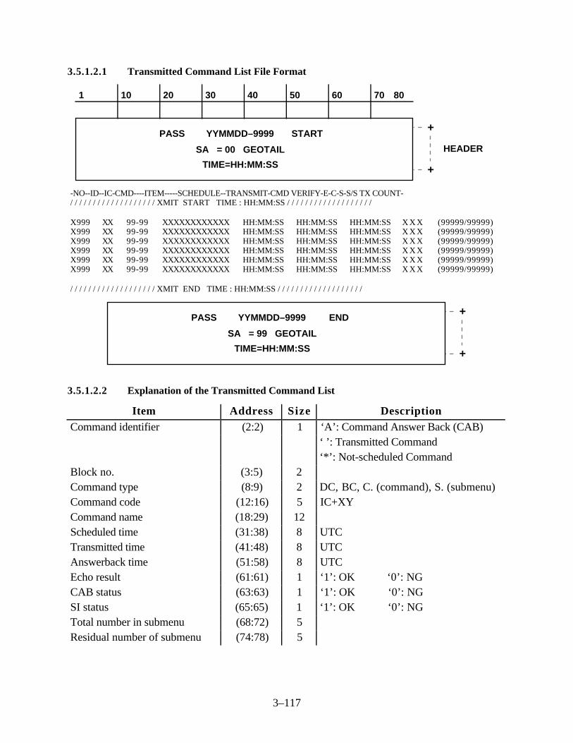
3–117
3.5.1.2.1 Transmitted Command List File Format
+
+
HEADER
PASS YYMMDD–9999 START
SA = 00 GEOTAIL
TIME=HH:MM:SS
1 10 20 30 40 50 60 70 80
-NO--ID--IC-CMD----ITEM-----SCHEDULE--TRANSMIT-CMD VERIFY-E-C-S-S/S TX COUNT-/ / / / / / / / / / / / / / / / / / / XMIT START TIME : HH:MM:SS / / / / / / / / / / / / / / / / / / /
X999 XX 99-99 XXXXXXXXXXXX HH:MM:SS HH:MM:SS HH:MM:SS X X X (99999/99999)X999 XX 99-99 XXXXXXXXXXXX HH:MM:SS HH:MM:SS HH:MM:SS X X X (99999/99999)X999 XX 99-99 XXXXXXXXXXXX HH:MM:SS HH:MM:SS HH:MM:SS X X X (99999/99999)X999 XX 99-99 XXXXXXXXXXXX HH:MM:SS HH:MM:SS HH:MM:SS X X X (99999/99999)X999 XX 99-99 XXXXXXXXXXXX HH:MM:SS HH:MM:SS HH:MM:SS X X X (99999/99999)X999 XX 99-99 XXXXXXXXXXXX HH:MM:SS HH:MM:SS HH:MM:SS X X X (99999/99999)
/ / / / / / / / / / / / / / / / / / / XMIT END TIME : HH:MM:SS / / / / / / / / / / / / / / / / / / /
+
+
PASS YYMMDD–9999 END
SA = 99 GEOTAIL
TIME=HH:MM:SS
3.5.1.2.2 Explanation of the Transmitted Command List
Item Address Size DescriptionCommand identifier (2:2) 1 ‘A’: Command Answer Back (CAB)
‘ ’: Transmitted Command‘*’: Not-scheduled Command
Block no. (3:5) 2Command type (8:9) 2 DC, BC, C. (command), S. (submenu)Command code (12:16) 5 IC+XYCommand name (18:29) 12Scheduled time (31:38) 8 UTCTransmitted time (41:48) 8 UTCAnswerback time (51:58) 8 UTCEcho result (61:61) 1 ‘1’: OK ‘0’: NGCAB status (63:63) 1 ‘1’: OK ‘0’: NGSI status (65:65) 1 ‘1’: OK ‘0’: NGTotal number in submenu (68:72) 5Residual number of submenu (74:78) 5

3–118
3.5.1.3 OP Table Contents
This section provides and explains the OP Table Contents.
3.5.1.3.1 OP Table Contents File Format
+
+
HEADER
OP TABLE CONTENTS
START DATE=YY.MM.DD
START TIME=YY.MM.DD
1 10 20 30 40 50 60 70 80
CE No. Mode CE/OG Address Loop No./Interval Date/Time999 XXXX 99 9999 YY.MM.DD HH.MM.SS999 XXXX 99 9999 YY.MM.DD HH.MM.SS999 XXXX 99 9999 YY.MM.DD HH.MM.SS999 XXXX 99 9999 YY.MM.DD HH.MM.SS999 XXXX 99 9999 YY.MM.DD HH.MM.SS999 XXXX 99 9999 YY.MM.DD HH.MM.SS999 XXXX 99 9999 YY.MM.DD HH.MM.SS999 XXXX 99 9999 YY.MM.DD HH.MM.SS
+
+
FOOTER
OP TABLE CONTENTS
END DATE=YY.MM.DD
END TIME=YY.MM.DD
3.5.1.3.2 Explanation of OP Table Contents
Item Address Size DescriptionCE no. (4:6) 2 ‘0’ ~ ‘127’Mode (16:19) 4 ‘----’: there is no mode
‘Jump’: Jump mode‘Loop’: Loop mode
CE/OG address (33:34) 2 Hexadecimal numeralLoop no./interval (50:53) 4 Loop count in case of back loop or the time
interval until the next OG is executed(binary numeral)
Date/time (63:79) 17 Executed date/time (UTC)
Note: ‘Jump’ and/or ‘Loop’ has already unfolded in this table

3–119
3.5.1.4 OP Executed Command List
This section provides and explains the OP Executed Command List.
3.5.1.4.1 OP Executed Command List File Format
+
+
HEADER OP EXECUTED COMMAND LIST
1 10 20 30 40 50 60 70 80
OG Address 99
No. ID IC+XY Command No. ID IC+XY Command
1 XX XX–XX XXXXXXXXXXXX 17 XX XX–XX XXXXXXXXXXXX
2 XX XX–XX XXXXXXXXXXXX 18 XX XX–XX XXXXXXXXXXXX
3 XX XX–XX XXXXXXXXXXXX 19 XX XX–XX XXXXXXXXXXXX
4 XX XX–XX XXXXXXXXXXXX 20 XX XX–XX XXXXXXXXXXXX
5 XX XX–XX XXXXXXXXXXXX 21 XX XX–XX XXXXXXXXXXXX
6 XX XX–XX XXXXXXXXXXXX 22 XX XX–XX XXXXXXXXXXXX
7 XX XX–XX XXXXXXXXXXXX 23 XX XX–XX XXXXXXXXXXXX
8 XX XX–XX XXXXXXXXXXXX 24 XX XX–XX XXXXXXXXXXXX
9 XX XX–XX XXXXXXXXXXXX 25 XX XX–XX XXXXXXXXXXXX
10 XX XX–XX XXXXXXXXXXXX 26 XX XX–XX XXXXXXXXXXXX
11 XX XX–XX XXXXXXXXXXXX 27 XX XX–XX XXXXXXXXXXXX
12 XX XX–XX XXXXXXXXXXXX 28 XX XX–XX XXXXXXXXXXXX
13 XX XX–XX XXXXXXXXXXXX 29 XX XX–XX XXXXXXXXXXXX
14 XX XX–XX XXXXXXXXXXXX 30 XX XX–XX XXXXXXXXXXXX
15 XX XX–XX XXXXXXXXXXXX 31 XX XX–XX XXXXXXXXXXXX
16 XX XX–XX XXXXXXXXXXXX 32 XX XX–XX XXXXXXXXXXXX
OG Address 99
No. ID IC+XY Command No. ID IC+XY Command
1 XX XX–XX XXXXXXXXXXXX 17 XX XX–XX XXXXXXXXXXXX
2 XX XX–XX XXXXXXXXXXXX 18 XX XX–XX XXXXXXXXXXXX
3 XX XX–XX XXXXXXXXXXXX 19 XX XX–XX XXXXXXXXXXXX

3–120
+
+
FOOTER OP EXECUTED COMMAND LIST
3.5.1.4.2 Explanation of OP Executed Command List
Item Address Size DescriptionOG Address (12:13) 2 Hexadecimal numeral
(7:8) 2 Command type : DC, BC(41:42) 2 Command type : DC, BC(11:15) 5(45:49) 5(18:29) 12 Command name(52:53) 12 Command name
Note: Organized Command (OG) includes maximum 32 items of OG Elements each of whichconsists of DC or BC with IC.
3 .6 Orbit Formats
Orbit files are provided in CDF. Refer to Reference 3 for information on extracting orbit data fromthe CDF. The CDF skeleton table for orbit data is shown in Table 3–10.
Note: The remainder of this section (i.e., 3.6) becomes effective with CDHF softwareRelease 6.2F.
POLAR orbit data files contain six additional variables:
• Calculated eccentric dipole magnetic local time• Calculated magnetic latitude• Computed L_SHELL parameter• Orbit rev number• Epoch of node crossing• Record number of next node crossing
These six variables are added when POLAR orbit CDF files are created as shown in Table 3–10a.
The information on the node crossings for the POLAR orbit was implemented as a linked list in theCDF file which provides a quicker mechanism to locate where the crossings occur rather thansearching through the file record by record.
The global section of the CDF has pointers to the first and last record in the linked list. In addition,the global section has the number of node crossings in the file, the orbit rev number for the firstand last crossings in the file.
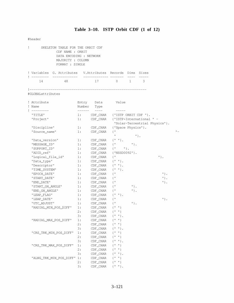
3–121
Table 3–10. ISTP Orbit CDF (1 of 12)
#header
! SKELETON TABLE FOR THE ORBIT CDF CDF NAME : ORBIT DATA ENCODING : NETWORK MAJORITY : COLUMN FORMAT : SINGLE
! Variables G. Attributes V.Attributes Records Dims Sizes! --------- ------------- ------------- ------- ---- ----- 14 48 17 0 1 3
!-------------------------------------------------------------#GLOBALattributes
! Attribute Entry Data Value! Name Number Type! --------- ------ ---- ----- "TITLE" 1: CDF_CHAR {"ISTP ORBIT CDF "}. "Project" 1: CDF_CHAR {"ISTP>International " - "Solar-Terrestrial Physics"}. "Discipline" 1: CDF_CHAR {"Space Physics"}. "Source_name" 1: CDF_CHAR {" "- " "}. "Data_version" 1: CDF_CHAR {" "}. "MESSAGE_ID" 1: CDF_CHAR {" "}. "SUPPORT_ID" 1: CDF_CHAR {" "}. "ADID_ref" 1: CDF_CHAR {"NSSD0092"}. "Logical_file_id" 1: CDF_CHAR {" "}. "Data_type" 1: CDF_CHAR {" "}. "Descriptor" 1: CDF_CHAR {" "}. "TIME_SYSTEM" 1: CDF_CHAR {" "}. "EPOCH_DATE" 1: CDF_CHAR {" "}. "START_DATE" 1: CDF_CHAR {" "}. "END_DATE" 1: CDF_CHAR {" "}. "START_GH_ANGLE" 1: CDF_CHAR {" "}. "END_GH_ANGLE" 1: CDF_CHAR {" "}. "LEAP_FLAG" 1: CDF_CHAR {" "}. "LEAP_DATE" 1: CDF_CHAR {" "}. "UTC_ADJUST" 1: CDF_CHAR {" "}. "RADIAL_MIN_POS_DIFF" 1: CDF_CHAR {" "} 2: CDF_CHAR {" "} 3: CDF_CHAR {" "}. "RADIAL_MAX_POS_DIFF" 1: CDF_CHAR {" "} 2: CDF_CHAR {" "} 3: CDF_CHAR {" "}. "CRS_TRK_MIN_POS_DIFF" 1: CDF_CHAR {" "} 2: CDF_CHAR {" "} 3: CDF_CHAR {" "}. "CRS_TRK_MAX_POS_DIFF" 1: CDF_CHAR {" "} 2: CDF_CHAR {" "} 3: CDF_CHAR {" "}. "ALNG_TRK_MIN_POS_DIFF" 1: CDF_CHAR {" "} 2: CDF_CHAR {" "} 3: CDF_CHAR {" "}.

3–122
Table 3–10. ISTP Orbit CDF (2 of 12)
"ALNG_TRK_MAX_POS_DIFF" 1: CDF_CHAR {" "} 2: CDF_CHAR {" "} 3: CDF_CHAR {" "}. "DELTA_R_MIN_POS_DIFF" 1: CDF_CHAR {" "} 2: CDF_CHAR {" "} 3: CDF_CHAR {" "}. "DELTA_R_MAX_POS_DIFF" 1: CDF_CHAR {" "} 2: CDF_CHAR {" "} 3: CDF_CHAR {" "}. "RADIAL_MIN_VEL_DIFF" 1: CDF_CHAR {" "} 2: CDF_CHAR {" "} 3: CDF_CHAR {" "}. "RADIAL_MAX_VEL_DIFF" 1: CDF_CHAR {" "} 2: CDF_CHAR {" "} 3: CDF_CHAR {" "}. "CRS_TRK_MIN_VEL_DIFF" 1: CDF_CHAR {" "} 2: CDF_CHAR {" "} 3: CDF_CHAR {" "}. "CRS_TRK_MAX_VEL_DIFF" 1: CDF_CHAR {" "} 2: CDF_CHAR {" "} 3: CDF_CHAR {" "}. "ALNG_TRK_MIN_VEL_DIFF" 1: CDF_CHAR {" "} 2: CDF_CHAR {" "} 3: CDF_CHAR {" "}. "ALNG_TRK_MAX_VEL_DIFF" 1: CDF_CHAR {" "} 2: CDF_CHAR {" "} 3: CDF_CHAR {" "}. "DELTA_V_MIN_VEL_DIFF" 1: CDF_CHAR {" "} 2: CDF_CHAR {" "} 3: CDF_CHAR {" "}. "DELTA_V_MAX_VEL_DIFF" 1: CDF_CHAR {" "} 2: CDF_CHAR {" "} 3: CDF_CHAR {" "}. "RADIAL_POS_RMS" 1: CDF_CHAR {" "}. "RADIAL_VEL_RMS" 1: CDF_CHAR {" "}. "CRS_TRK_POS_RMS" 1: CDF_CHAR {" "}. "CRS_TRK_VEL_RMS" 1: CDF_CHAR {" "}. "ALNG_TRK_POS_RMS" 1: CDF_CHAR {" "}. "ALNG_TRK_VEL_RMS" 1: CDF_CHAR {" "}. "TOTAL_POS_RMS" 1: CDF_CHAR {" "}. "TOTAL_VEL_RMS" 1: CDF_CHAR {" "}. "COMMENT1" 1: CDF_CHAR {" "- " "- " "}. "COMMENT2" 1: CDF_CHAR {" "- " "- " "}. "TEXT" 1: CDF_CHAR {"TBS"}. "MODS" 1: CDF_CHAR {"Originated Monday, May 13,1991"} 2: CDF_CHAR {"Modified June 13, 1991 "- "for version 2.1"} 3: CDF_CHAR {"Modified October 2,1991 for new"- " global attributes, incr sizes"}

3–123
Table 3–10. ISTP Orbit CDF (3 of 12)
4: CDF_CHAR {"Modified 11/11/91 Add sun "- "vector, replace space id with "- "support id"} 5: CDF_CHAR {"Modified 1992 Feb 11 to use the "- "variable name TIME and type "- "CDF_INT4 instead of "} 6: CDF_CHAR {"EPOCH and CDF_EPOCH for the "- "time tags CCR 490"} 7: CDF_CHAR {"Modified 6/2/92 add project, "- "discipline, source_name, "- "data_version, title, and "} 8: CDF_CHAR {"mods to global section; add "- "validmin, validmax, labl_ptr_1 "- "and monoton "} 9: CDF_CHAR {"attributes to some variables; "- "put epoch time back in, "- "rename time to "} 10: CDF_CHAR {"time_pb5; add label_time to "- "variables"} 11: CDF_CHAR {"Modified 11/07/92 to use Epoch "- "and Time_PB5 variable name"} 12: CDF_CHAR {"Modified 6/2/93 add ADID_ref "- "and Logical_file_id"} 13: CDF_CHAR {"7/5/94 - CCR ISTP 1852 "- "updated CDHF skeleton to "- "CDF standards - JT"} 14: CDF_CHAR {"9/21/94 - Added 24 new global " - "attributes to log the ephemeris "} 15: CDF_CHAR {"comparison summary report from " - "the definitive FDF orbit " - "file. CCR 1932"} 16: CDF_CHAR {"11/7/94 - Merged CCR 1852 " - "changes and corrected errors "} 17: CDF_CHAR {"made in CCR 1852. ICCR 1884"} 18: CDF_CHAR {"12/7/94 - Modified MODS to " - "follow ISTP standards. " - "ICCR 1885"} 19: CDF_CHAR {"01/05/95 - add heliocentric " - "coordinate system. CCR 1889"} 20: CDF_CHAR {"2/28/95 - added COMMENT1 and"- " COMMENT2 for CCR "}."FIRST_CROSSING" 1: CDF_INT4 {0}."LAST_CROSSING" 1: CDF_INT4 {0}."NUM_CROSSING" 1: CDF_INT4 {0}."INIT_ORB_REV" 1: CDF_INT4 {0}."LAST_ORB_REV" 1: CDF_INT4 {0}.
!-------------------------------------------------------------VARIABLEattributes
"FIELDNAM" "VALIDMIN"

3–124
Table 3–10. ISTP Orbit CDF (4 of 12)
"VALIDMAX" "SCALEMIN" "SCALEMAX" "LABLAXIS" "UNITS" "FORMAT" "LABL_PTR_1" "UNIT_PTR" "FORM_PTR" "MONOTON" "DEPEND_0" "DEPEND_1" "FILLVAL" "VAR_TYPE" "DICT_KEY"
!-------------------------------------------------------------#variables
! Variable Data Number Record Dim! Name Type Elements Variance Variance! ------- ---- -------- -------- -------- "Epoch" CDF_EPOCH 1 T F
! Attribute Data Value! Name Type!----------- ----- ------ "FIELDNAM" CDF_CHAR { "Orbit Epoch Time" } "VALIDMIN" CDF_EPOCH { 01-JUL-1992 00:00:00.000 } "VALIDMAX" CDF_EPOCH { 31-DEC-2020 23:59:59.000 } "SCALEMIN" CDF_EPOCH { 01-JUL-1992 00:00:00.000 } "SCALEMAX" CDF_EPOCH { 31-DEC-2020 23:59:59.000 } "LABLAXIS" CDF_CHAR { "Epoch" } "UNITS" CDF_CHAR { "ms" } "MONOTON" CDF_CHAR { "INCREASE" } "FILLVAL" CDF_REAL8 { -1.0E31 } "VAR_TYPE" CDF_CHAR { "data" } "DICT_KEY" CDF_CHAR { " " }.
!-------------------------------------------------------------! Variable Data Number Record Dim! Name Type Elements Variance Variance! ------- ---- -------- -------- -------- "Time_PB5" CDF_INT4 1 T T
! Attribute Data Value! Name Type!----------- ----- ------ "FIELDNAM" CDF_CHAR { "Orbit PB5 Time" } "VALIDMIN" CDF_INT4 { 1992, 183, 0 } "VALIDMAX" CDF_INT4 { 2020, 366, 86399000 } "SCALEMIN" CDF_INT4 { 1992, 183, 0 } "SCALEMAX" CDF_INT4 { 2020, 366, 86399000 } "LABL_PTR_1" CDF_CHAR { "label_time" }
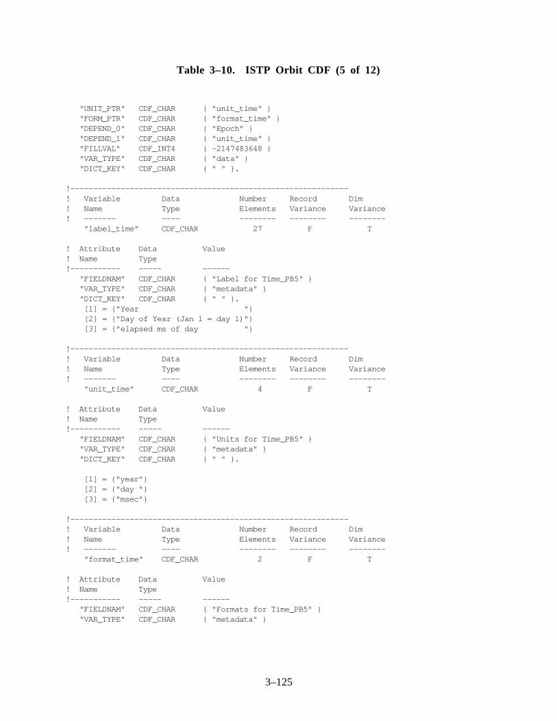
3–125
Table 3–10. ISTP Orbit CDF (5 of 12)
"UNIT_PTR" CDF_CHAR { "unit_time" } "FORM_PTR" CDF_CHAR { "format_time" } "DEPEND_0" CDF_CHAR { "Epoch" } "DEPEND_1" CDF_CHAR { "unit_time" } "FILLVAL" CDF_INT4 { -2147483648 } "VAR_TYPE" CDF_CHAR { "data" } "DICT_KEY" CDF_CHAR { " " }.
!-------------------------------------------------------------! Variable Data Number Record Dim! Name Type Elements Variance Variance! ------- ---- -------- -------- -------- "label_time" CDF_CHAR 27 F T
! Attribute Data Value! Name Type!----------- ----- ------ "FIELDNAM" CDF_CHAR { "Label for Time_PB5" } "VAR_TYPE" CDF_CHAR { "metadata" } "DICT_KEY" CDF_CHAR { " " }. [1] = {"Year "} [2] = {"Day of Year (Jan 1 = day 1)"} [3] = {"elapsed ms of day "}
!-------------------------------------------------------------! Variable Data Number Record Dim! Name Type Elements Variance Variance! ------- ---- -------- -------- -------- "unit_time" CDF_CHAR 4 F T
! Attribute Data Value! Name Type!----------- ----- ------ "FIELDNAM" CDF_CHAR { "Units for Time_PB5" } "VAR_TYPE" CDF_CHAR { "metadata" } "DICT_KEY" CDF_CHAR { " " }.
[1] = {"year"} [2] = {"day "} [3] = {"msec"}
!-------------------------------------------------------------! Variable Data Number Record Dim! Name Type Elements Variance Variance! ------- ---- -------- -------- -------- "format_time" CDF_CHAR 2 F T
! Attribute Data Value! Name Type!----------- ----- ------ "FIELDNAM" CDF_CHAR { "Formats for Time_PB5" } "VAR_TYPE" CDF_CHAR { "metadata" }

3–126
Table 3–10. ISTP Orbit CDF (6 of 12)
"DICT_KEY" CDF_CHAR { " " }.
[1] = {"I4"} [2] = {"I3"} [3] = {"I8"}
!-------------------------------------------------------------! Variable Data Number Record Dim! Name Type Elements Variance Variance! -------- ---- -------- -------- -------- "GCI_POS" CDF_REAL8 1 T T
! Attribute Data Value! Name Type!----------- ----- ------ "FIELDNAM" CDF_CHAR { "GCI Cartesian Position" } "VALIDMIN" CDF_REAL8 { -1800000.0 } "VALIDMAX" CDF_REAL8 { 1800000.0 } "SCALEMIN" CDF_REAL8 { -1800000.0 } "SCALEMAX" CDF_REAL8 { 1800000.0 } "LABLAXIS" CDF_CHAR { "Cart Pos" } "UNITS" CDF_CHAR { "km" } "FORMAT" CDF_CHAR { "F17.5" } "DEPEND_0" CDF_CHAR { "Epoch" } "DEPEND_1" CDF_CHAR { "cartesian" } "FILLVAL" CDF_REAL8 { -1.0E31 } "VAR_TYPE" CDF_CHAR { "data" } "DICT_KEY" CDF_CHAR { " " }.
!-------------------------------------------------------------! Variable Data Number Record Dim! Name Type Elements Variance Variance! ------- ---- -------- -------- -------- "GCI_VEL" CDF_REAL8 1 T T
! Attribute Data Value! Name Type!----------- ----- ------ "FIELDNAM" CDF_CHAR { "GCI Cartesian Velocity" } "VALIDMIN" CDF_REAL8 { -12.0 } "VALIDMAX" CDF_REAL8 { 12.0 } "SCALEMIN" CDF_REAL8 { -12.0 } "SCALEMAX" CDF_REAL8 { 12.0 } "LABL_PTR_1" CDF_CHAR { "label_v" } "UNITS" CDF_CHAR { "km/sec" } "FORMAT" CDF_CHAR { "F12.7" } "DEPEND_0" CDF_CHAR { "Epoch" } "DEPEND_1" CDF_CHAR { "cartesian" } "FILLVAL" CDF_REAL8 { -1.0E31 } "VAR_TYPE" CDF_CHAR { "data" } "DICT_KEY" CDF_CHAR { " " }.

3–127
Table 3–10. ISTP Orbit CDF (7 of 12)
!-------------------------------------------------------------! Variable Data Number Record Dim! Name Type Elements Variance Variance! ------- ---- -------- -------- -------- "label_v" CDF_CHAR 2 F T
! Attribute Data Value! Name Type!----------- ----- ------ "FIELDNAM" CDF_CHAR { "Label for velocity" } "VAR_TYPE" CDF_CHAR { "metadata" } "DICT_KEY" CDF_CHAR { " " }.
[1] = {"vx"} [2] = {"vy"} [3] = {"vz"}
!-------------------------------------------------------------! Variable Data Number Record Dim! Name Type Elements Variance Variance! ------- ---- -------- -------- -------- "cartesian" CDF_CHAR 1 F T
! Attribute Data Value! Name Type!----------- ----- ------ "FIELDNAM" CDF_CHAR { "Components in cartesian coord." } "VAR_TYPE" CDF_CHAR { "metadata" } "DICT_KEY" CDF_CHAR { "ISTP>vector>cartesian" }.
[1] = {"x"} [2] = {"y"} [3] = {"z"}
!-------------------------------------------------------------! Variable Data Number Record Dim! Name Type Elements Variance Variance! -------- ---- -------- -------- -------- "GSE_POS" CDF_REAL8 1 T T
! Attribute Data Value! Name Type!----------- ----- ------ "FIELDNAM" CDF_CHAR { "GSE Cartesian Position" } "VALIDMIN" CDF_REAL8 { -1800000.0 } "VALIDMAX" CDF_REAL8 { 1800000.0 } "SCALEMIN" CDF_REAL8 { -1800000.0 } "SCALEMAX" CDF_REAL8 { 1800000.0 } "LABLAXIS" CDF_CHAR { "Cart pos" } "UNITS" CDF_CHAR { "km" } "FORMAT" CDF_CHAR { "F17.5" } "DEPEND_0" CDF_CHAR { "Epoch" } "DEPEND_1" CDF_CHAR { "cartesian" } "FILLVAL" CDF_REAL8 { -1.0E31 }

3–128
Table 3–10. ISTP Orbit CDF (8 of 12)
"VAR_TYPE" CDF_CHAR { "data" } "DICT_KEY" CDF_CHAR { " " }.
!-------------------------------------------------------------! Variable Data Number Record Dim! Name Type Elements Variance Variance! ------- ---- -------- -------- -------- "GSE_VEL" CDF_REAL8 1 T T
! Attribute Data Value! Name Type!----------- ----- ------ "FIELDNAM" CDF_CHAR { "GSE Cartesian Velocity" } "VALIDMIN" CDF_REAL8 { -12.0 } "VALIDMAX" CDF_REAL8 { 12.0 } "SCALEMIN" CDF_REAL8 { -12.0 } "SCALEMAX" CDF_REAL8 { 12.0 } "LABL_PTR_1" CDF_CHAR { "label_v" } "UNITS" CDF_CHAR { "km/sec" } "FORMAT" CDF_CHAR { "F12.7" } "DEPEND_0" CDF_CHAR { "Epoch" } "DEPEND_1" CDF_CHAR { "cartesian" } "FILLVAL" CDF_REAL8 { -1.0E31 } "VAR_TYPE" CDF_CHAR { "data" } "DICT_KEY" CDF_CHAR { " " }.
!-------------------------------------------------------------! Variable Data Number Record Dim! Name Type Elements Variance Variance! -------- ---- -------- -------- -------- "GSM_POS" CDF_REAL8 1 T T
! Attribute Data Value! Name Type!----------- ----- ------ "FIELDNAM" CDF_CHAR { "GSM Cartesian Position" } "VALIDMIN" CDF_REAL8 { -1800000.0 } "VALIDMAX" CDF_REAL8 { 1800000.0 } "SCALEMIN" CDF_REAL8 { -1800000.0 } "SCALEMAX" CDF_REAL8 { 1800000.0 } "LABLAXIS" CDF_CHAR { "Cart pos" } "UNITS" CDF_CHAR { "km" } "FORMAT" CDF_CHAR { "F17.5" } "DEPEND_0" CDF_CHAR { "Epoch" } "DEPEND_1" CDF_CHAR { "cartesian" } "FILLVAL" CDF_REAL8 { -1.0E31 } "VAR_TYPE" CDF_CHAR { "data" } "DICT_KEY" CDF_CHAR { " " }
!-------------------------------------------------------------! Variable Data Number Record Dim! Name Type Elements Variance Variance! ------- ---- -------- -------- -------- "GSM_VEL" CDF_REAL8 1 T T

3–129
Table 3–10. ISTP Orbit CDF (9 of 12)
! Attribute Data Value! Name Type!----------- ----- ------ "FIELDNAM" CDF_CHAR { "GSM Cartesian Velocity" } "VALIDMIN" CDF_REAL8 { -12.0 } "VALIDMAX" CDF_REAL8 { 12.0 } "SCALEMIN" CDF_REAL8 { -12.0 } "SCALEMAX" CDF_REAL8 { 12.0 } "LABL_PTR_1" CDF_CHAR { "label_v" } "UNITS" CDF_CHAR { "km/sec" } "FORMAT" CDF_CHAR { "F12.7" } "DEPEND_0" CDF_CHAR { "Epoch" } "DEPEND_1" CDF_CHAR { "cartesian" } "FILLVAL" CDF_REAL8 { -1.0E31 } "VAR_TYPE" CDF_CHAR { "data" } "DICT_KEY" CDF_CHAR { " " }.
!-------------------------------------------------------------! Variable Data Number Record Dim! Name Type Elements Variance Variance! ------- ---- -------- -------- -------- "SUN_VECTOR" CDF_REAL8 1 T T
! Attribute Data Value! Name Type!----------- ----- ------ "FIELDNAM" CDF_CHAR { "GCI Sun Postion Vector" } "VALIDMIN" CDF_REAL8 { -1.6E8 } "VALIDMAX" CDF_REAL8 { 1.6E8 } "SCALEMIN" CDF_REAL8 { -1.6E8 } "SCALEMAX" CDF_REAL8 { 1.6E8 } "LABLAXIS" CDF_CHAR { "Sun pos V" } "UNITS" CDF_CHAR { "km" } "FORMAT" CDF_CHAR { "F17.5" } "DEPEND_0" CDF_CHAR { "Epoch" } "DEPEND_1" CDF_CHAR { "cartesian" } "FILLVAL" CDF_REAL8 { -1.0E31 } "VAR_TYPE" CDF_CHAR { "data" } "DICT_KEY" CDF_CHAR { " " }.
!-------------------------------------------------------------! Variable Data Number Record Dim! Name Type Elements Variance Variance! -------- ---- -------- -------- -------- "HEC_POS" CDF_REAL8 1 T T
! Attribute Data Value! Name Type!----------- ----- ------ "FIELDNAM" CDF_CHAR { "HEC Cartesian Position" } "VALIDMIN" CDF_REAL8 { -1800000.0 } "VALIDMAX" CDF_REAL8 { 1800000.0 } "SCALEMIN" CDF_REAL8 { -1800000.0 } "SCALEMAX" CDF_REAL8 { 1800000.0 }

3–130
Table 3–10. ISTP Orbit CDF (10 of 12)
"LABLAXIS" CDF_CHAR { "Cart Pos" } "UNITS" CDF_CHAR { "km" } "FORMAT" CDF_CHAR { "F17.5" } "DEPEND_0" CDF_CHAR { "Epoch" } "DEPEND_1" CDF_CHAR { "cartesian" } "FILLVAL" CDF_REAL8 { -1.0E31 } "VAR_TYPE" CDF_CHAR { "data" } "DICT_KEY" CDF_CHAR { " " }.
!-------------------------------------------------------------! Variable Data Number Record Dim! Name Type Elements Variance Variance! ------- ---- -------- -------- -------- "HEC_VEL" CDF_REAL8 1 T T
! Attribute Data Value! Name Type!----------- ----- ------ "FIELDNAM" CDF_CHAR { "HEC Cartesian Velocity" } "VALIDMIN" CDF_REAL8 { -12.0 } "VALIDMAX" CDF_REAL8 { 12.0 } "SCALEMIN" CDF_REAL8 { -12.0 } "SCALEMAX" CDF_REAL8 { 12.0 } "LABL_PTR_1" CDF_CHAR { "label_v" } "UNITS" CDF_CHAR { "km/sec" } "FORMAT" CDF_CHAR { "F12.7" } "DEPEND_0" CDF_CHAR { "Epoch" } "DEPEND_1" CDF_CHAR { "cartesian" } "FILLVAL" CDF_REAL8 { -1.0E31 } "VAR_TYPE" CDF_CHAR { "data" } "DICT_KEY" CDF_CHAR { " " }.
!-------------------------------------------------------------! Variable Data Number Record Dim! Name Type Elements Variance Variance! ------- ---- -------- -------- -------- "CRN" CDF_INT4 1 T F! Attribute Data Value! Name Type Carrington Rotation Number!----------- ----- ------ "FIELDNAM" CDF_CHAR { " " } "VALIDMIN" CDF_INT4 { 1857 } "VALIDMAX" CDF_INT4 { 2239 } "SCALEMIN" CDF_INT4 { 1857 } "SCALEMAX" CDF_INT4 { 2239 } "LABLAXIS" CDF_CHAR { "CRN" } "UNITS" CDF_CHAR { " " } "FORMAT" CDF_CHAR { "I4" } "DEPEND_0" CDF_CHAR { "Epoch" } "FILLVAL" CDF_INT4 { -2147483648 } "VAR_TYPE" CDF_CHAR { "data" } "DICT_KEY" CDF_CHAR { " " }.

3–131
Table 3–10. ISTP Orbit CDF (11 of 12)
!-------------------------------------------------------------! Variable Data Number Record Dim! Name Type Elements Variance Variance! ------- ---- -------- -------- -------- "LONG_EARTH" CDF_REAL8 1 T F
! Attribute Data Value! Name Type!----------- ----- ------ "FIELDNAM" CDF_CHAR { "Heliographic Long of the Earth" } "VALIDMIN" CDF_REAL8 { 0.0 } "VALIDMAX" CDF_REAL8 { 6.283185307 } "SCALEMIN" CDF_REAL8 { 0.0 } "SCALEMAX" CDF_REAL8 { 6.283185307 } "LABLAXIS" CDF_CHAR { "Helio Long" } "UNITS" CDF_CHAR { "rad" } "FORMAT" CDF_CHAR { "F7.3" } "DEPEND_0" CDF_CHAR { "Epoch" } "FILLVAL" CDF_REAL8 { -1.0E31 } "VAR_TYPE" CDF_CHAR { "data" } "DICT_KEY" CDF_CHAR { " " }.
!-------------------------------------------------------------! Variable Data Number Record Dim! Name Type Elements Variance Variance! ------- ---- -------- -------- -------- "LAT_EARTH" CDF_REAL8 1 T F
! Attribute Data Value! Name Type!----------- ----- ------ "FIELDNAM" CDF_CHAR { "Heliographic Lat of the Earth" } "VALIDMIN" CDF_REAL8 { -1.570796327 } "VALIDMAX" CDF_REAL8 { 1.570796327 } "SCALEMIN" CDF_REAL8 { -1.570796327 } "SCALEMAX" CDF_REAL8 { 1.570796327 } "LABLAXIS" CDF_CHAR { "Helio Lat" } "UNITS" CDF_CHAR { "rad" } "FORMAT" CDF_CHAR { "F7.3" } "DEPEND_0" CDF_CHAR { "Epoch" } "FILLVAL" CDF_REAL8 { -1.0E31 } "VAR_TYPE" CDF_CHAR { "data" } "DICT_KEY" CDF_CHAR { " " }.
!-------------------------------------------------------------! Variable Data Number Record Dim! Name Type Elements Variance Variance! ------- ---- -------- -------- -------- "LONG_SPACE" CDF_REAL8 1 T F
! Attribute Data Value! Name Type!----------- ----- ------ "FIELDNAM" CDF_CHAR { "Heliographic Long of Craft" }
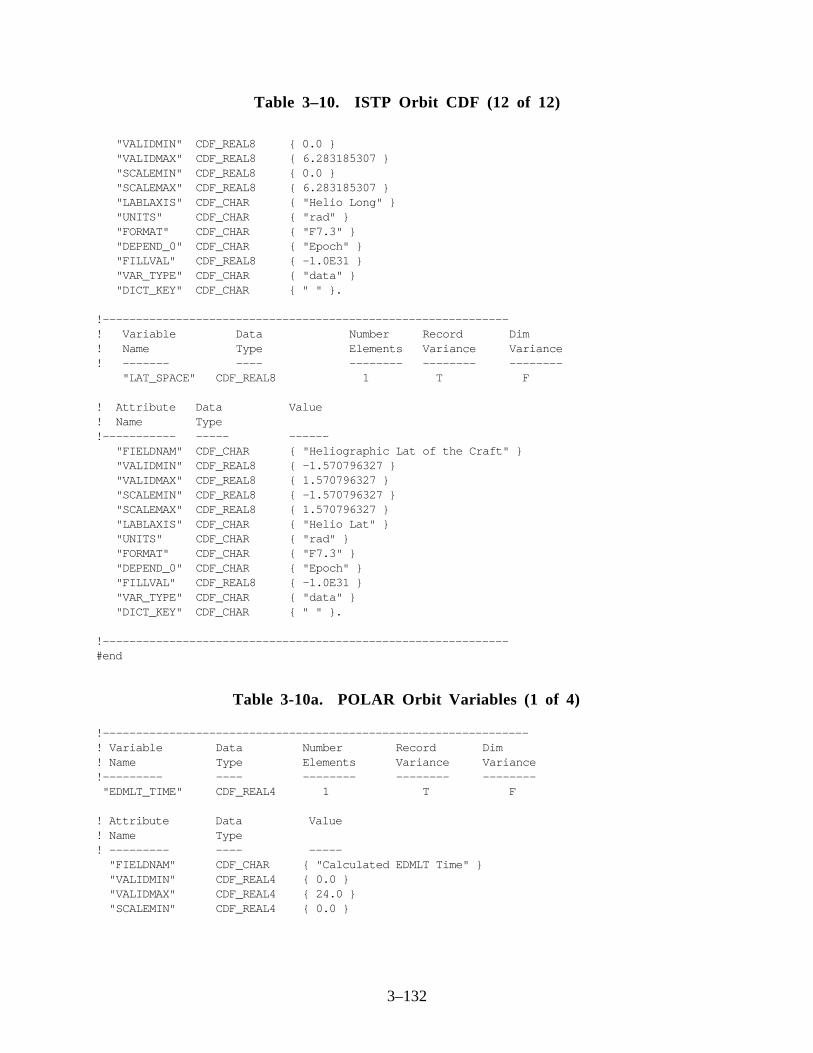
3–132
Table 3–10. ISTP Orbit CDF (12 of 12)
"VALIDMIN" CDF_REAL8 { 0.0 } "VALIDMAX" CDF_REAL8 { 6.283185307 } "SCALEMIN" CDF_REAL8 { 0.0 } "SCALEMAX" CDF_REAL8 { 6.283185307 } "LABLAXIS" CDF_CHAR { "Helio Long" } "UNITS" CDF_CHAR { "rad" } "FORMAT" CDF_CHAR { "F7.3" } "DEPEND_0" CDF_CHAR { "Epoch" } "FILLVAL" CDF_REAL8 { -1.0E31 } "VAR_TYPE" CDF_CHAR { "data" } "DICT_KEY" CDF_CHAR { " " }.
!-------------------------------------------------------------! Variable Data Number Record Dim! Name Type Elements Variance Variance! ------- ---- -------- -------- -------- "LAT_SPACE" CDF_REAL8 1 T F
! Attribute Data Value! Name Type!----------- ----- ------ "FIELDNAM" CDF_CHAR { "Heliographic Lat of the Craft" } "VALIDMIN" CDF_REAL8 { -1.570796327 } "VALIDMAX" CDF_REAL8 { 1.570796327 } "SCALEMIN" CDF_REAL8 { -1.570796327 } "SCALEMAX" CDF_REAL8 { 1.570796327 } "LABLAXIS" CDF_CHAR { "Helio Lat" } "UNITS" CDF_CHAR { "rad" } "FORMAT" CDF_CHAR { "F7.3" } "DEPEND_0" CDF_CHAR { "Epoch" } "FILLVAL" CDF_REAL8 { -1.0E31 } "VAR_TYPE" CDF_CHAR { "data" } "DICT_KEY" CDF_CHAR { " " }.
!-------------------------------------------------------------#end
Table 3-10a. POLAR Orbit Variables (1 of 4)
!----------------------------------------------------------------! Variable Data Number Record Dim! Name Type Elements Variance Variance!--------- ---- -------- -------- -------- "EDMLT_TIME" CDF_REAL4 1 T F
! Attribute Data Value! Name Type! --------- ---- ----- "FIELDNAM" CDF_CHAR { "Calculated EDMLT Time" } "VALIDMIN" CDF_REAL4 { 0.0 } "VALIDMAX" CDF_REAL4 { 24.0 } "SCALEMIN" CDF_REAL4 { 0.0 }

3–133
Table 3-10a. POLAR Orbit Variables (2 of 4)
"SCALEMAX" CDF_REAL4 { 24.0 } "LABLAXIS" CDF_CHAR { "CALC EDMLT" } "UNITS" CDF_CHAR { "HOUR" } "FORMAT" CDF_CHAR { "F8.4" } "DEPEND_0" CDF_CHAR { "Epoch" } "FILLVAL" CDF_REAL8 { -1.0E31 } "VAR_TYPE" CDF_CHAR { "data" } "DICT_KEY" CDF_CHAR { " " }.
!----------------------------------------------------------------! Variable Data Number Record Dim! Name Type Elements Variance Variance!--------- ---- -------- -------- -------- "MAG_LATITUDE" CDF_REAL4 1 T F
! Attribute Data Value! Name Type! --------- ---- ----- "FIELDNAM" CDF_CHAR { "MAGNETIC LATITUDE" } "VALIDMIN" CDF_REAL4 { -90.0 } "VALIDMAX" CDF_REAL4 { 90.0 } "SCALEMIN" CDF_REAL4 { -90.0 } "SCALEMAX" CDF_REAL4 { 90.0 } "LABLAXIS" CDF_CHAR { "MAG LAT" } "UNITS" CDF_CHAR { "DEG" } "FORMAT" CDF_CHAR { "F8.4" } "DEPEND_0" CDF_CHAR { "Epoch" } "FILLVAL" CDF_REAL8 { -1.0E31 } "VAR_TYPE" CDF_CHAR { "data" } "DICT_KEY" CDF_CHAR { " " }.
!----------------------------------------------------------------! Variable Data Number Record Dim! Name Type Elements Variance Variance!--------- ---- -------- -------- -------- "L_SHELL" CDF_REAL4 1 T F
! Attribute Data Value! Name Type! --------- ---- ----- "FIELDNAM" CDF_CHAR { "L_SHELL" } "VALIDMIN" CDF_REAL4 { 1.0 } "VALIDMAX" CDF_REAL4 { 20000.0 } "SCALEMIN" CDF_REAL4 { 1.0 } "SCALEMAX" CDF_REAL4 { 20000.0 } "LABLAXIS" CDF_CHAR { "L_SHELL" } "UNITS" CDF_CHAR { "EARTH RADI" } "FORMAT" CDF_CHAR { "F11.4" } "DEPEND_0" CDF_CHAR { "Epoch" } "FILLVAL" CDF_REAL8 { -1.0E31 }

3–134
Table 3-10a. POLAR Orbit Variables (3 of 4)
"VAR_TYPE" CDF_CHAR { "data" } "DICT_KEY" CDF_CHAR { " " }.
!----------------------------------------------------------------! Variable Data Number Record Dim! Name Type Elements Variance Variance!--------- ---- -------- -------- -------- "ORB_REV_NUM" CDF_INT 1 T F
! Attribute Data Value! Name Type! --------- ---- ----- "FIELDNAM" CDF_CHAR { "Orbit Revolution No." } "VALIDMIN" CDF_INT4 { 0 } "VALIDMAX" CDF_INT4 { 5000 } "SCALEMIN" CDF_INT4 { 0 } "SCALEMAX" CDF_INT4 { 5000 } "LABLAXIS" CDF_CHAR { "Orb Rev" } "UNITS" CDF_CHAR { " " } "FORMATS" CDF_CHAR { "I5" } "MONOTON" CDF_CHAR { " " } "DEPEND_O" CDF_CHAR { "Epoch" } "FILLVAL" CDF_INT4 { –2147483648 } "VAR_TYPE" CDF_CHAR { "data" }. "DICT_KEY" CDF_CHAR { " " }
----------------------------------------------------------------! Variable Data Number Record Dim! Name Type Elements Variance Variance!--------- ---- -------- -------- -------- "NEXT_CROSS" CDF_INT 1 T F
! Attribute Data Value! Name Type! --------- ---- ----- "FIELDNAM" CDF_CHAR { "Next Orbit Crossing" } "VALIDMIN" CDF_INT4 { 0 } "VALIDMAX" CDF_INT4 { 100 } "SCALEMIN" CDF_INT4 { 0 } "SCALEMAX" CDF_INT4 { 100 } "LABLAXIS" CDF_CHAR { "Next Cross" } "UNITS" CDF_CHAR { " " } "FORMATS" CDF_CHAR { "I5" } "MONOTON" CDF_CHAR { " " } "DEPEND_O" CDF_CHAR { "Epoch" } "FILLVAL" CDF_INT4 { –2147483648 } "VAR_TYPE" CDF_CHAR { "data" }. "DICT_KEY" CDF_CHAR { " " }

3–135
Table 3-10a. POLAR Orbit Variables (4 of 4)
----------------------------------------------------------------! Variable Data Number Record Dim! Name Type Elements Variance Variance!--------- ---- -------- -------- -------- "ORB_CROSSING CDF_INT 1 T F TIME"
! Attribute Data Value! Name Type! --------- ---- ----- "FIELDNAM" CDF_CHAR { "Crossing Time" } "VALIDMIN" CDF_EPOCH { 01-JUL-1992 00:00:00.000 } "VALIDMAX" CDF_EPOCH { 31–DEC–2020 23:59:59.000 } "SCALEMIN" CDF_EPOCH { 01–JUL–1992 00:00:00.000 } "SCALEMAX" CDF_EPOCH { 31–DEC–2020 23:59:59.000 } "LABLAXIS" CDF_CHAR { "Epoch" } "UNITS" CDF_CHAR { "ms" } "FORMATS" CDF_CHAR { "F8.4" } "MONOTON" CDF_CHAR { "INCREASE" } "DEPEND_O" CDF_CHAR { "Epoch" } "FILLVAL" CDF_INT4 { –1.0E31 } "VAR_TYPE" CDF_CHAR { "data" }. "DICT_KEY: CDF_CHAR { " " }
----------------------------------------------------------------#end
Note: The information in Table 3-10a becomes effective with the CDHF Release 6.2F software.
The data records referenced in the linked list have additional information related to the nodecrossing: orbit rev number, time of node crossing, and record number of next crossing. If therecord number is zero, then the linked list is terminated.
Listed below are the gAttributes for accessing the linked list:
attribute_name purposeFIRST_CROSSING Record number for first node crossing in the fileLAST_CROSSING Record number for last node crossing in the fileNUM_CROSSING Number of node crossings in the fileINIT_ORB_REV Orbit rev number for first node crossing in the fileLAST_ORB_REV Orbit rev number for last node crossing in the file
Listed below are the rVariables associated with node crossing:
variable_name purposeORB_REV_NUM Orbit rev numberORB_CROSSING_TIME Epoch of node crossingNEXT_CROSS Record number for next node crossing in the file

3–136
3 .7 Attitude Formats
ISTP attitude files are provided in CDF. Refer to Reference 3 for information on extracting attitudedata from the CDF. The CDF skeleton table for GEOTAIL, WIND, and POLAR spin-stablizedattitude data is presented in Table 3–11. The CDF skeleton table for SOHO attitude data is shownin Table 3–12, and the CDF skeleton table for POLAR despun attitude data is shown inTable 3–13.
Table 3–11. ISTP GEOTAIL, WIND, and POLAR Attitude Spin-StabilizedCDF (1 of 7)
#header
! SKELETON TABLE FOR THE ISTP ATTITUDE SPIN-STABILIZED CDF
CDF NAME : istp_attitude_spin_stabilized DATA ENCODING : NETWORK MAJORITY : COLUMN FORMAT : SINGLE
! Variables G. Attributes V.Attributes Records Dims Sizes! --------- ------------- ------------- ------- --- ----- 12 19 17 0 1 3
!-------------------------------------------------------------#GLOBALattributes
! Attribute Entry Data Value! Name Number Type! --------- ------ ---- ----- "TITLE" 1: CDF_CHAR {"ISTP attitude " - "spin-stabilized CDF"}. "Project" 1: CDF_CHAR {"ISTP>International " - "Solar-Terrestrial Physics"}. "Discipline" 1: CDF_CHAR {"Space Physics"}. "Source_name" 1: CDF_CHAR {" "}. "Data_version" 1: CDF_CHAR {" "}. "MESSAGE_ID" 1: CDF_CHAR {" "}. "SUPPORT_ID" 1: CDF_CHAR {" "}. "ADID_ref" 1: CDF_CHAR {"NSSD0093"}. "Logical_file_id" 1: CDF_CHAR {" "}. "Data_type" 1: CDF_CHAR {"AT>Attitude"}. "Descriptor" 1: CDF_CHAR {" "}. "STABILIZATION_TYPE" 1: CDF_CHAR {" "}. "START_DATE" 1: CDF_CHAR {" "}. "END_DATE" 1: CDF_CHAR {" "}. "STEP_SIZE" 1: CDF_CHAR {" "}. "GCI_RA_ERR" 1: CDF_CHAR {" "}. "GCI_DECL_ERR" 1: CDF_CHAR {" "}. "TEXT" 1: CDF_CHAR {"TBS"}. "MODS" 1: CDF_CHAR {"6/13/91 - Original " - "Implementation"} 2: CDF_CHAR {"9/18/91 - Modified for new " - "attitude file format changes." -

3–137
Table 3–11. ISTP GEOTAIL, WIND, and POLAR Attitude Spin-StabilizedCDF (2 of 7)
" ICCR 881"} 3: CDF_CHAR {"2/11/92 - Used the variable " - "name TIME and type CDF_INT4 " - "and size 3 instead of "} 4: CDF_CHAR {"EPOCH, CDF_EPOCH and 1 for " - "the time tags. CCR 490"} 5: CDF_CHAR {"6/1/92 - Added global " - "attributes TITLE, PROJECT, " - "DISCIPLINE, SOURCE_NAME, "} 6: CDF_CHAR {"DATA_VERSION, and MODS; " - "added variable attributes " - "VALIDMIN, VALIDMAX, "} 7: CDF_CHAR {"LABL_PTR_1, and MONOTON; " - "added variables EPOCH and " - "LABEL_TIME; "} 8: CDF_CHAR {"changed variable name TIME " - "to TIME_PB5. CCR 1066"} 9: CDF_CHAR {"11/07/92 - use cdf variable " - "Epoch and Time_PB5"} 10: CDF_CHAR {"6/8/93 - Added global " - "attributes ADID_ref and " - "Logical_file_id. CCR 1092"} 11: CDF_CHAR {"7/5/94 - CCR ISTP 1852, " - "updated CDHF skeleton to " - "CDF standards - JT"} 12: CDF_CHAR {"9/20/94 - Added global " - "attributes GCI_RA_ERR and " - "GCI_DECL_ERR. CCR 1932"} 13: CDF_CHAR {"11/7/94 - Merged CCR 1852 " - "changes and corrected errors "} 14: CDF_CHAR {"made in CCR 1852. ICCR 1884"} 15: CDF_CHAR {"12/7/94 - Modified MODS and " - "LABLAXIS to follow ISTP " - "standards. ICCR 1885"}.!-------------------------------------------------------------#VARIABLEattributes
"FIELDNAM" "VALIDMIN" "VALIDMAX" "SCALEMIN" "SCALEMAX" "LABLAXIS" "UNITS" "FORMAT" "LABL_PTR_1" "UNIT_PTR" "FORM_PTR" "MONOTON" "DEPEND_0" "DEPEND_1" "FILLVAL"

3–138
Table 3–11. ISTP GEOTAIL, WIND, and POLAR Attitude Spin-StabilizedCDF (3 of 7)
"VAR_TYPE" "DICT_KEY"
!-------------------------------------------------------------#variables
! Variable Data Number Record Dim! Name Type Elements Variance Variance! ------- ---- -------- -------- -------- "Epoch" CDF_EPOCH 1 T F
! Attribute Data Value! Name Type!----------- ----- ------ "FIELDNAM" CDF_CHAR { "Attitude EPOCH time" } "VALIDMIN" CDF_EPOCH { 01-JUL-1992 00:00:00.000 } "VALIDMAX" CDF_EPOCH { 31-DEC-2020 23:59:59.000 } "SCALEMIN" CDF_EPOCH { 01-JUL-1992 00:00:00.000 } "SCALEMAX" CDF_EPOCH { 31-DEC-2020 23:59:59.000 } "LABLAXIS" CDF_CHAR { "Epoch" } "UNITS" CDF_CHAR { "ms" } "MONOTON" CDF_CHAR { "INCREASE" } "FILLVAL" CDF_REAL8 { -1.0E31 } "VAR_TYPE" CDF_CHAR { "data" } "DICT_KEY" CDF_CHAR { " " }.
!-------------------------------------------------------------! Variable Data Number Record Dim! Name Type Elements Variance Variance! ------- ---- -------- -------- -------- "Time_PB5" CDF_INT4 1 T T
! Attribute Data Value! Name Type!----------- ----- ------ "FIELDNAM" CDF_CHAR { "Attitude PB5 time" } "VALIDMIN" CDF_INT4 { 1992, 183, 0 } "VALIDMAX" CDF_INT4 { 2020, 366, 86399000 } "SCALEMIN" CDF_INT4 { 1992, 183, 0 } "SCALEMAX" CDF_INT4 { 2020, 366, 86399000 } "LABL_PTR_1" CDF_CHAR { "label_time" } "UNIT_PTR" CDF_CHAR { "unit_time" } "FORM_PTR" CDF_CHAR { "format_time" } "DEPEND_0" CDF_CHAR { "Epoch" } "DEPEND_1" CDF_CHAR { "unit_time" } "FILLVAL" CDF_INT4 { -2147483648 } "VAR_TYPE" CDF_CHAR { "data" } "DICT_KEY" CDF_CHAR { " " }.

3–139
Table 3–11. ISTP GEOTAIL, WIND, and POLAR Attitude Spin-StabilizedCDF (4 of 7)
!-------------------------------------------------------------! Variable Data Number Record Dim! Name Type Elements Variance Variance! ------- ---- -------- -------- -------- "label_time" CDF_CHAR 27 F T
! Attribute Data Value! Name Type!----------- ----- ------ "FIELDNAM" CDF_CHAR { "Label for Time_PB5" } "VAR_TYPE" CDF_CHAR { "metadata" } "DICT_KEY" CDF_CHAR { " " }. [1] = { "Year " } [2] = { "Day of Year (Jan 1 = day 1)" } [3] = { "Elapsed ms of Day " }
!-------------------------------------------------------------! Variable Data Number Record Dim! Name Type Elements Variance Variance! ------- ---- -------- -------- -------- "unit_time" CDF_CHAR 4 F T
! Attribute Data Value! Name Type!----------- ----- ------ "FIELDNAM" CDF_CHAR { "Units for Time_PB5" } "VAR_TYPE" CDF_CHAR { "metadata" } "DICT_KEY" CDF_CHAR { " " }.
[1] = { "year" } [2] = { "day " } [3] = { "msec" }
!-------------------------------------------------------------! Variable Data Number Record Dim! Name Type Elements Variance Variance! ------- ---- -------- -------- -------- "format_time" CDF_CHAR 2 F T
! Attribute Data Value! Name Type!----------- ----- ------ "FIELDNAM" CDF_CHAR { "Formats for Time_PB5" } "VAR_TYPE" CDF_CHAR { "metadata" } "DICT_KEY" CDF_CHAR { " " }.
[1] = { "I4" } [2] = { "I3" } [3] = { "I8" }

3–140
Table 3–11. ISTP GEOTAIL, WIND, and POLAR Attitude Spin-StabilizedCDF (5 of 7)
!-------------------------------------------------------------! Variable Data Number Record Dim! Name Type Elements Variance Variance! -------- ---- -------- -------- -------- "BODY_SPIN_RATE" CDF_REAL4 1 T F
! Attribute Data Value! Name Type!----------- ----- ------ "FIELDNAM" CDF_CHAR { "Body spin rate" } "VALIDMIN" CDF_REAL4 { 0.0 } "VALIDMAX" CDF_REAL4 { 100.0 } "SCALEMIN" CDF_REAL4 { 0.0 } "SCALEMAX" CDF_REAL4 { 100.0 } "LABLAXIS" CDF_CHAR { "Spin Rate" } "UNITS" CDF_CHAR { "rpm" } "FORMAT" CDF_CHAR { "F9.3" } "DEPEND_0" CDF_CHAR { "Epoch" } "FILLVAL" CDF_REAL4 { -1.0E31 } "VAR_TYPE" CDF_CHAR { "data" } "DICT_KEY" CDF_CHAR { " " }.
!-------------------------------------------------------------! Variable Data Number Record Dim! Name Type Elements Variance Variance! -------- ---- -------- -------- -------- "GCI_R_ASCENSION" CDF_REAL4 1 T F
! Attribute Data Value! Name Type!----------- ----- ------ "FIELDNAM" CDF_CHAR { "GCI right ascension" } "VALIDMIN" CDF_REAL4 { 0.0 } "VALIDMAX" CDF_REAL4 { 6.283185307 } "SCALEMIN" CDF_REAL4 { 0.0 } "SCALEMAX" CDF_REAL4 { 6.283185307 } "LABLAXIS" CDF_CHAR { "GCI R Ascn" } "UNITS" CDF_CHAR { "rad" } "FORMAT" CDF_CHAR { "F7.3" } "DEPEND_0" CDF_CHAR { "Epoch" } "FILLVAL" CDF_REAL4 { -1.0E31 } "VAR_TYPE" CDF_CHAR { "data" } "DICT_KEY" CDF_CHAR { " " }.
!-------------------------------------------------------------! Variable Data Number Record Dim! Name Type Elements Variance Variance! ------- ---- -------- -------- -------- "GCI_DECLINATION" CDF_REAL4 1 T F

3–141
Table 3–11. ISTP GEOTAIL, WIND, and POLAR Attitude Spin-StabilizedCDF (6 of 7)
! Attribute Data Value! Name Type!----------- ----- ------ "FIELDNAM" CDF_CHAR { "GCI declination" } "VALIDMIN" CDF_REAL4 { -1.570796327 } "VALIDMAX" CDF_REAL4 { 1.570796327 } "SCALEMIN" CDF_REAL4 { -1.570796327 } "SCALEMAX" CDF_REAL4 { 1.570796327 } "LABLAXIS" CDF_CHAR { "GCI Decli" } "UNITS" CDF_CHAR { "rad" } "FORMAT" CDF_CHAR { "F7.3" } "DEPEND_0" CDF_CHAR { "Epoch" } "FILLVAL" CDF_REAL4 { -1.0E31 } "VAR_TYPE" CDF_CHAR { "data" } "DICT_KEY" CDF_CHAR { " " }.
!-------------------------------------------------------------! Variable Data Number Record Dim! Name Type Elements Variance Variance! -------- ---- -------- -------- -------- "GSE_R_ASCENSION" CDF_REAL4 1 T F
! Attribute Data Value! Name Type!----------- ----- ------ "FIELDNAM" CDF_CHAR { "GSE right ascension" } "VALIDMIN" CDF_REAL4 { 0.0 } "VALIDMAX" CDF_REAL4 { 6.283185307 } "SCALEMIN" CDF_REAL4 { 0.0 } "SCALEMAX" CDF_REAL4 { 6.283185307 } "LABLAXIS" CDF_CHAR { "GSE R Ascn" } "UNITS" CDF_CHAR { "rad" } "FORMAT" CDF_CHAR { "F7.3" } "DEPEND_0" CDF_CHAR { "Epoch" } "FILLVAL" CDF_REAL4 { -1.0E31 } "VAR_TYPE" CDF_CHAR { "data" } "DICT_KEY" CDF_CHAR { " " }.
!-------------------------------------------------------------! Variable Data Number Record Dim! Name Type Elements Variance Variance! ------- ---- -------- -------- -------- "GSE_DECLINATION" CDF_REAL4 1 T F
! Attribute Data Value! Name Type!----------- ----- ------ "FIELDNAM" CDF_CHAR { "GSE declination" } "VALIDMIN" CDF_REAL4 { -1.570796327 } "VALIDMAX" CDF_REAL4 { 1.570796327 } "SCALEMIN" CDF_REAL4 { -1.570796327 } "SCALEMAX" CDF_REAL4 { 1.570796327 } "LABLAXIS" CDF_CHAR { "GSE Decli" }

3–142
Table 3–11. ISTP GEOTAIL, WIND, and POLAR Attitude Spin-StabilizedCDF (7 of 7)
"UNITS" CDF_CHAR { "rad" } "FORMAT" CDF_CHAR { "F7.3" } "DEPEND_0" CDF_CHAR { "Epoch" } "FILLVAL" CDF_REAL4 { -1.0E31 } "VAR_TYPE" CDF_CHAR { "data" } "DICT_KEY" CDF_CHAR { " " }.!-------------------------------------------------------------! Variable Data Number Record Dim! Name Type Elements Variance Variance! -------- ---- -------- -------- -------- "GSM_R_ASCENSION" CDF_REAL4 1 T F! Attribute Data Value! Name Type!----------- ----- ------ "FIELDNAM" CDF_CHAR { "GSM right ascension" } "VALIDMIN" CDF_REAL4 { 0.0 } "VALIDMAX" CDF_REAL4 { 6.283185307 } "SCALEMIN" CDF_REAL4 { 0.0 } "SCALEMAX" CDF_REAL4 { 6.283185307 } "LABLAXIS" CDF_CHAR { "GSM R Ascn" } "UNITS" CDF_CHAR { "rad" } "FORMAT" CDF_CHAR { "F7.3" } "DEPEND_0" CDF_CHAR { "Epoch" } "FILLVAL" CDF_REAL4 { -1.0E31 } "VAR_TYPE" CDF_CHAR { "data" } "DICT_KEY" CDF_CHAR { " " }.
!-------------------------------------------------------------! Variable Data Number Record Dim! Name Type Elements Variance Variance! ------- ---- -------- -------- -------- "GSM_DECLINATION" CDF_REAL4 1 T F
! Attribute Data Value! Name Type!----------- ----- ------ "FIELDNAM" CDF_CHAR { "GSM declination" } "VALIDMIN" CDF_REAL4 { -1.570796327 } "VALIDMAX" CDF_REAL4 { 1.570796327 } "SCALEMIN" CDF_REAL4 { -1.570796327 } "SCALEMAX" CDF_REAL4 { 1.570796327 } "LABLAXIS" CDF_CHAR { "GSM Decli" } "UNITS" CDF_CHAR { "rad" } "FORMAT" CDF_CHAR { "F7.3" } "DEPEND_0" CDF_CHAR { "Epoch" } "FILLVAL" CDF_REAL4 { -1.0E31 } "VAR_TYPE" CDF_CHAR { "data" } "DICT_KEY" CDF_CHAR { " " }.
!-------------------------------------------------------------#end

3–143
Table 3–12. ISTP SOHO Attitude CDF (1 of 13)
#header
! SKELETON TABLE FOR THE ISTP SOHO ATTITUDE CDF
CDF NAME : istp_soho_attitude DATA ENCODING : NETWORK MAJORITY : COLUMN FORMAT : SINGLE
! Variables G. Attributes V.Attributes Records Dims Sizes! --------- ------------- ------------- ------- --- ----- 26 14 17 0 1 3
!-------------------------------------------------------------#GLOBALattributes
! Attribute Entry Data Value! Name Number Type! --------- ------ ---- ----- "TITLE" 1: CDF_CHAR {"ISTP SOHO 3-axis stabilized " - "attitude CDF"}. "Project" 1: CDF_CHAR {"ISTP>International " - "Solar-Terrestrial Physics"}. "Discipline" 1: CDF_CHAR {"Space Physics"}. "Source_name" 1: CDF_CHAR {"SOHO>Solar Heliospheric " - "Observatory"}. "Data_type" 1: CDF_CHAR {"AT>Attitude"}. "Descriptor" 1: CDF_CHAR {"DEF>Definitive data"}. "Data_version" 1: CDF_CHAR {" "}. "TEXT" 1: CDF_CHAR {"Data: 10 minute intervals"}. "STABILIZATION_TYPE" 1: CDF_CHAR {"A"}. "START_DATE" 1: CDF_CHAR {" "}. "END_DATE" 1: CDF_CHAR {" "}. "ADID_ref" 1: CDF_CHAR {"NSSD0208"}. "Logical_file_id" 1: CDF_CHAR {" "}. "MODS" 1: CDF_CHAR {"5/6/94 - Original " - "Implementation"}.
!-------------------------------------------------------------#VARIABLEattributes
"FIELDNAM" "VALIDMIN" "VALIDMAX" "SCALEMIN" "SCALEMAX" "LABLAXIS" "UNITS" "FORMAT" "MONOTON" "LABL_PTR_1" "UNIT_PTR" "FORM_PTR" "DEPEND_0"

3–144
Table 3–12. ISTP SOHO Attitude CDF (2 of 13)
"DEPEND_1" "FILLVAL" "VAR_TYPE" "DICT_KEY"
!-------------------------------------------------------------#variables
! Variable Data Number Record Dim! Name Type Elements Variance Variance! ------- ---- -------- -------- -------- "Epoch" CDF_EPOCH 1 T F
! Attribute Data Value! Name Type!----------- ----- ------ "FIELDNAM" CDF_CHAR { "SOHO attitude EPOCH time" } "VALIDMIN" CDF_EPOCH { 01-JUL-1992 00:00:00.000 } "VALIDMAX" CDF_EPOCH { 31-DEC-2020 23:59:59.000 } "SCALEMIN" CDF_EPOCH { 01-JUL-1992 00:00:00.000 } "SCALEMAX" CDF_EPOCH { 31-DEC-2020 23:59:59.000 } "LABLAXIS" CDF_CHAR { "Epoch" } "UNITS" CDF_CHAR { "ms" } "MONOTON" CDF_CHAR { "INCREASE" } "FILLVAL" CDF_REAL8 { -1.0E31 } "VAR_TYPE" CDF_CHAR { "data" } "DICT_KEY" CDF_CHAR { " " }.
!-------------------------------------------------------------! Variable Data Number Record Dim! Name Type Elements Variance Variance! ------- ---- -------- -------- -------- "Time_PB5" CDF_INT4 1 T T
! Attribute Data Value! Name Type!----------- ----- ------ "FIELDNAM" CDF_CHAR { "SOHO attitude PB5 time" } "VALIDMIN" CDF_INT4 { 1992, 183, 0 } "VALIDMAX" CDF_INT4 { 2020, 366, 86399000 } "SCALEMIN" CDF_INT4 { 1992, 183, 0 } "SCALEMAX" CDF_INT4 { 2020, 366, 86399000 } "LABL_PTR_1" CDF_CHAR { "label_time" } "UNIT_PTR" CDF_CHAR { "unit_time" } "FORM_PTR" CDF_CHAR { "format_time" } "DEPEND_0" CDF_CHAR { "Epoch" } "DEPEND_1" CDF_CHAR { "unit_time" } "FILLVAL" CDF_INT4 { -2147483648 } "VAR_TYPE" CDF_CHAR { "data" } "DICT_KEY" CDF_CHAR { " " }.
!-------------------------------------------------------------

3–145
Table 3–12. ISTP SOHO Attitude CDF (3 of 13)
! Variable Data Number Record Dim! Name Type Elements Variance Variance! ------- ---- -------- -------- -------- "label_time" CDF_CHAR 27 F T
! Attribute Data Value! Name Type!----------- ----- ------ "FIELDNAM" CDF_CHAR { "Label for Time_PB5" } "VAR_TYPE" CDF_CHAR { "metadata" } "DICT_KEY" CDF_CHAR { " " }.
[1] = { "Year " } [2] = { "Day of Year (Jan 1 = day 1)" } [3] = { "Elapsed ms of Day " }
!-------------------------------------------------------------! Variable Data Number Record Dim! Name Type Elements Variance Variance! ------- ---- -------- -------- -------- "unit_time" CDF_CHAR 4 F T
! Attribute Data Value! Name Type!----------- ----- ------ "FIELDNAM" CDF_CHAR { "Units for Time_PB5" } "VAR_TYPE" CDF_CHAR { "metadata" } "DICT_KEY" CDF_CHAR { " " }.
[1] = { "year" } [2] = { "day " } [3] = { "msec" }
!-------------------------------------------------------------! Variable Data Number Record Dim! Name Type Elements Variance Variance! ------- ---- -------- -------- -------- "format_time" CDF_CHAR 2 F T
! Attribute Data Value! Name Type!----------- ----- ------ "FIELDNAM" CDF_CHAR { "Format for Time_PB5" } "VAR_TYPE" CDF_CHAR { "metadata" } "DICT_KEY" CDF_CHAR { " " }.
[1] = { "I4" } [2] = { "I3" } [3] = { "I8" }

3–146
Table 3–12. ISTP SOHO Attitude CDF (4 of 13)
!-------------------------------------------------------------! Variable Data Number Record Dim! Name Type Elements Variance Variance! -------- ---- -------- -------- -------- "SAT_PITCH_AVG" CDF_REAL4 1 T F
! Attribute Data Value! Name Type!----------- ----- ------ "FIELDNAM" CDF_CHAR { "S/C body axis avg pitch angle" } "VALIDMIN" CDF_REAL4 { -3.141592654 } "VALIDMAX" CDF_REAL4 { 3.141592654 } "SCALEMIN" CDF_REAL4 { -3.141592654 } "SCALEMAX" CDF_REAL4 { 3.141592654 } "LABLAXIS" CDF_CHAR { "Sat p avg" } "UNITS" CDF_CHAR { "rad" } "FORMAT" CDF_CHAR { "F9.5" } "DEPEND_0" CDF_CHAR { "Epoch" } "FILLVAL" CDF_REAL4 { -1.0E31 } "VAR_TYPE" CDF_CHAR { "data" } "DICT_KEY" CDF_CHAR { " " }.
!-------------------------------------------------------------! Variable Data Number Record Dim! Name Type Elements Variance Variance! ------- ---- -------- -------- -------- "SAT_ROLL_AVG" CDF_REAL4 1 T F
! Attribute Data Value! Name Type!----------- ----- ------ "FIELDNAM" CDF_CHAR { "S/C body axis avg roll angle" } "VALIDMIN" CDF_REAL4 { -3.141592654 } "VALIDMAX" CDF_REAL4 { 3.141592654 } "SCALEMIN" CDF_REAL4 { -3.141592654 } "SCALEMAX" CDF_REAL4 { 3.141592654 } "LABLAXIS" CDF_CHAR { "Sat r avg" } "UNITS" CDF_CHAR { "rad" } "FORMAT" CDF_CHAR { "F9.5" } "DEPEND_0" CDF_CHAR { "Epoch" } "FILLVAL" CDF_REAL4 { -1.0E31 } "VAR_TYPE" CDF_CHAR { "data" } "DICT_KEY" CDF_CHAR { " " }.
!-------------------------------------------------------------! Variable Data Number Record Dim! Name Type Elements Variance Variance! ------- ---- -------- -------- -------- "SAT_YAW_AVG" CDF_REAL4 1 T F
! Attribute Data Value! Name Type!----------- ----- ------ "FIELDNAM" CDF_CHAR { "S/C body axis avg yaw angle" }

3–147
Table 3–12. ISTP SOHO Attitude CDF (5 of 13)
"VALIDMIN" CDF_REAL4 { -1.570796327 } "VALIDMAX" CDF_REAL4 { 1.570796327 } "SCALEMIN" CDF_REAL4 { -1.570796327 } "SCALEMAX" CDF_REAL4 { 1.570796327 } "LABLAXIS" CDF_CHAR { "Sat y avg" } "UNITS" CDF_CHAR { "rad" } "FORMAT" CDF_CHAR { "F9.5" } "DEPEND_0" CDF_CHAR { "Epoch" } "FILLVAL" CDF_REAL4 { -1.0E31 } "VAR_TYPE" CDF_CHAR { "data" } "DICT_KEY" CDF_CHAR { " " }.
!-------------------------------------------------------------! Variable Data Number Record Dim! Name Type Elements Variance Variance! -------- ---- -------- -------- -------- "SAR_PITCH_AVG" CDF_REAL4 1 T F
! Attribute Data Value! Name Type!----------- ----- ------ "FIELDNAM" CDF_CHAR { "Solar axis refer avg pitch angle" } "VALIDMIN" CDF_REAL4 { -3.141592654 } "VALIDMAX" CDF_REAL4 { 3.141592654 } "SCALEMIN" CDF_REAL4 { -3.141592654 } "SCALEMAX" CDF_REAL4 { 3.141592654 } "LABLAXIS" CDF_CHAR { "Sar r avg" } "UNITS" CDF_CHAR { "rad" } "FORMAT" CDF_CHAR { "F9.5" } "DEPEND_0" CDF_CHAR { "Epoch" } "FILLVAL" CDF_REAL4 { -1.0E31 } "VAR_TYPE" CDF_CHAR { "data" } "DICT_KEY" CDF_CHAR { " " }.
!-------------------------------------------------------------! Variable Data Number Record Dim! Name Type Elements Variance Variance! -------- ---- -------- -------- -------- "SAR_ROLL_AVG" CDF_REAL4 1 T F
! Attribute Data Value! Name Type!----------- ----- ------ "FIELDNAM" CDF_CHAR { "Solar axis refer avg roll angle" } "VALIDMIN" CDF_REAL4 { -3.141592654 } "VALIDMAX" CDF_REAL4 { 3.141592654 } "SCALEMIN" CDF_REAL4 { -3.141592654 } "SCALEMAX" CDF_REAL4 { 3.141592654 } "LABLAXIS" CDF_CHAR { "GCI p avg" } "UNITS" CDF_CHAR { "rad" } "FORMAT" CDF_CHAR { "F9.5" } "DEPEND_0" CDF_CHAR { "Epoch" } "FILLVAL" CDF_REAL4 { -1.0E31 }

3–148
Table 3–12. ISTP SOHO Attitude CDF (6 of 13)
"VAR_TYPE" CDF_CHAR { "data" } "DICT_KEY" CDF_CHAR { " " }.
!-------------------------------------------------------------! Variable Data Number Record Dim! Name Type Elements Variance Variance! -------- ---- -------- -------- -------- "GCI_PITCH_AVG" CDF_REAL4 1 T F
! Attribute Data Value! Name Type!----------- ----- ------ "FIELDNAM" CDF_CHAR { "GCI average pitch angle" } "VALIDMIN" CDF_REAL4 { -3.141592654 } "VALIDMAX" CDF_REAL4 { 3.141592654 } "SCALEMIN" CDF_REAL4 { -3.141592654 } "SCALEMAX" CDF_REAL4 { 3.141592654 } "LABLAXIS" CDF_CHAR { "GCI p avg" } "UNITS" CDF_CHAR { "rad" } "FORMAT" CDF_CHAR { "F9.5" } "DEPEND_0" CDF_CHAR { "Epoch" } "FILLVAL" CDF_REAL4 { -1.0E31 } "VAR_TYPE" CDF_CHAR { "data" } "DICT_KEY" CDF_CHAR { " " }.
!-------------------------------------------------------------! Variable Data Number Record Dim! Name Type Elements Variance Variance! ------- ---- -------- -------- -------- "GCI_ROLL_AVG" CDF_REAL4 1 T F
! Attribute Data Value! Name Type!----------- ----- ------ "FIELDNAM" CDF_CHAR { "GCI average roll angle" } "VALIDMIN" CDF_REAL4 { -3.141592654 } "VALIDMAX" CDF_REAL4 { 3.141592654 } "SCALEMIN" CDF_REAL4 { -3.141592654 } "SCALEMAX" CDF_REAL4 { 3.141592654 } "LABLAXIS" CDF_CHAR { "GCI r avg" } "UNITS" CDF_CHAR { "rad" } "FORMAT" CDF_CHAR { "F9.5" } "DEPEND_0" CDF_CHAR { "Epoch" } "FILLVAL" CDF_REAL4 { -1.0E31 } "VAR_TYPE" CDF_CHAR { "data" } "DICT_KEY" CDF_CHAR { " " }.
!-------------------------------------------------------------! Variable Data Number Record Dim! Name Type Elements Variance Variance! ------- ---- -------- -------- -------- "GCI_YAW_AVG" CDF_REAL4 1 T F
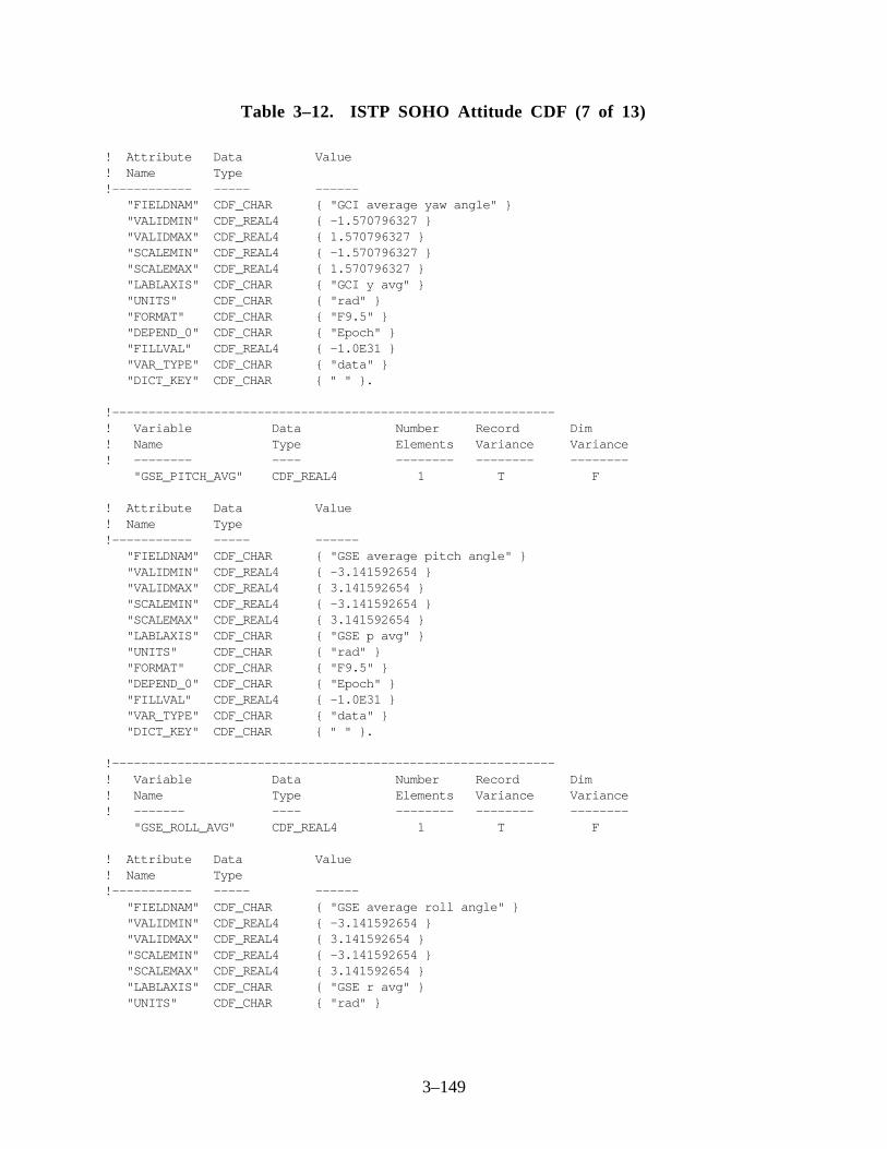
3–149
Table 3–12. ISTP SOHO Attitude CDF (7 of 13)
! Attribute Data Value! Name Type!----------- ----- ------ "FIELDNAM" CDF_CHAR { "GCI average yaw angle" } "VALIDMIN" CDF_REAL4 { -1.570796327 } "VALIDMAX" CDF_REAL4 { 1.570796327 } "SCALEMIN" CDF_REAL4 { -1.570796327 } "SCALEMAX" CDF_REAL4 { 1.570796327 } "LABLAXIS" CDF_CHAR { "GCI y avg" } "UNITS" CDF_CHAR { "rad" } "FORMAT" CDF_CHAR { "F9.5" } "DEPEND_0" CDF_CHAR { "Epoch" } "FILLVAL" CDF_REAL4 { -1.0E31 } "VAR_TYPE" CDF_CHAR { "data" } "DICT_KEY" CDF_CHAR { " " }.
!-------------------------------------------------------------! Variable Data Number Record Dim! Name Type Elements Variance Variance! -------- ---- -------- -------- -------- "GSE_PITCH_AVG" CDF_REAL4 1 T F
! Attribute Data Value! Name Type!----------- ----- ------ "FIELDNAM" CDF_CHAR { "GSE average pitch angle" } "VALIDMIN" CDF_REAL4 { -3.141592654 } "VALIDMAX" CDF_REAL4 { 3.141592654 } "SCALEMIN" CDF_REAL4 { -3.141592654 } "SCALEMAX" CDF_REAL4 { 3.141592654 } "LABLAXIS" CDF_CHAR { "GSE p avg" } "UNITS" CDF_CHAR { "rad" } "FORMAT" CDF_CHAR { "F9.5" } "DEPEND_0" CDF_CHAR { "Epoch" } "FILLVAL" CDF_REAL4 { -1.0E31 } "VAR_TYPE" CDF_CHAR { "data" } "DICT_KEY" CDF_CHAR { " " }.
!-------------------------------------------------------------! Variable Data Number Record Dim! Name Type Elements Variance Variance! ------- ---- -------- -------- -------- "GSE_ROLL_AVG" CDF_REAL4 1 T F
! Attribute Data Value! Name Type!----------- ----- ------ "FIELDNAM" CDF_CHAR { "GSE average roll angle" } "VALIDMIN" CDF_REAL4 { -3.141592654 } "VALIDMAX" CDF_REAL4 { 3.141592654 } "SCALEMIN" CDF_REAL4 { -3.141592654 } "SCALEMAX" CDF_REAL4 { 3.141592654 } "LABLAXIS" CDF_CHAR { "GSE r avg" } "UNITS" CDF_CHAR { "rad" }

3–150
Table 3–12. ISTP SOHO Attitude CDF (8 of 13)
"FORMAT" CDF_CHAR { "F9.5" } "DEPEND_0" CDF_CHAR { "Epoch" } "FILLVAL" CDF_REAL4 { -1.0E31 } "VAR_TYPE" CDF_CHAR { "data" } "DICT_KEY" CDF_CHAR { " " }.
!-------------------------------------------------------------! Variable Data Number Record Dim! Name Type Elements Variance Variance! -------- ---- -------- -------- -------- "GSE_YAW_AVG" CDF_REAL4 1 T F
! Attribute Data Value! Name Type!----------- ----- ------ "FIELDNAM" CDF_CHAR { "GSE average yaw angle" } "VALIDMIN" CDF_REAL4 { -1.570796327 } "VALIDMAX" CDF_REAL4 { 1.570796327 } "SCALEMIN" CDF_REAL4 { -1.570796327 } "SCALEMAX" CDF_REAL4 { 1.570796327 } "LABLAXIS" CDF_CHAR { "GSE y avg" } "UNITS" CDF_CHAR { "rad" } "FORMAT" CDF_CHAR { "F9.5" } "DEPEND_0" CDF_CHAR { "Epoch" } "FILLVAL" CDF_REAL4 { -1.0E31 } "VAR_TYPE" CDF_CHAR { "data" } "DICT_KEY" CDF_CHAR { " " }.
!-------------------------------------------------------------! Variable Data Number Record Dim! Name Type Elements Variance Variance! -------- ---- -------- -------- -------- "GSM_PITCH_AVG" CDF_REAL4 1 T F
! Attribute Data Value! Name Type!----------- ----- ------ "FIELDNAM" CDF_CHAR { "GSM average pitch angle" } "VALIDMIN" CDF_REAL4 { -3.141592654 } "VALIDMAX" CDF_REAL4 { 3.141592654 } "SCALEMIN" CDF_REAL4 { -3.141592654 } "SCALEMAX" CDF_REAL4 { 3.141592654 } "LABLAXIS" CDF_CHAR { "GSM p avg" } "UNITS" CDF_CHAR { "rad" } "FORMAT" CDF_CHAR { "F9.5" } "DEPEND_0" CDF_CHAR { "Epoch" } "FILLVAL" CDF_REAL4 { -1.0E31 } "VAR_TYPE" CDF_CHAR { "data" } "DICT_KEY" CDF_CHAR { " " }.

3–151
Table 3–12. ISTP SOHO Attitude CDF (9 of 13)
!-------------------------------------------------------------! Variable Data Number Record Dim! Name Type Elements Variance Variance! ------- ---- -------- -------- -------- "GSM_ROLL_AVG" CDF_REAL4 1 T F! Attribute Data Value! Name Type!----------- ----- ------ "FIELDNAM" CDF_CHAR { "GSM average roll angle" } "VALIDMIN" CDF_REAL4 { -3.141592654 } "VALIDMAX" CDF_REAL4 { 3.141592654 } "SCALEMIN" CDF_REAL4 { -3.141592654 } "SCALEMAX" CDF_REAL4 { 3.141592654 } "LABLAXIS" CDF_CHAR { "GSM r avg" } "UNITS" CDF_CHAR { "rad" } "FORMAT" CDF_CHAR { "F9.5" } "DEPEND_0" CDF_CHAR { "Epoch" } "FILLVAL" CDF_REAL4 { -1.0E31 } "VAR_TYPE" CDF_CHAR { "data" } "DICT_KEY" CDF_CHAR { " " }.
!-------------------------------------------------------------! Variable Data Number Record Dim! Name Type Elements Variance Variance! -------- ---- -------- -------- -------- "GSM_YAW_AVG" CDF_REAL4 1 T F
! Attribute Data Value! Name Type!----------- ----- ------ "FIELDNAM" CDF_CHAR { "GSM average yaw angle" } "VALIDMIN" CDF_REAL4 { -1.570796327 } "VALIDMAX" CDF_REAL4 { 1.570796327 } "SCALEMIN" CDF_REAL4 { -1.570796327 } "SCALEMAX" CDF_REAL4 { 1.570796327 } "LABLAXIS" CDF_CHAR { "GSM y avg" } "UNITS" CDF_CHAR { "rad" } "FORMAT" CDF_CHAR { "F9.5" } "DEPEND_0" CDF_CHAR { "Epoch" } "FILLVAL" CDF_REAL4 { -1.0E31 } "VAR_TYPE" CDF_CHAR { "data" } "DICT_KEY" CDF_CHAR { " " }.
!-------------------------------------------------------------! Variable Data Number Record Dim! Name Type Elements Variance Variance! -------- ---- -------- -------- -------- "SAT_PITCH_STDDEV" CDF_REAL4 1 T F
! Attribute Data Value! Name Type!----------- ----- ------ "FIELDNAM" CDF_CHAR { "S/C axis std dev of pitch ang" } "VALIDMIN" CDF_REAL4 { -3.141592654 }

3–152
Table 3–12. ISTP SOHO Attitude CDF (10 of 13)
"VALIDMAX" CDF_REAL4 { 3.141592654 } "SCALEMIN" CDF_REAL4 { -3.141592654 } "SCALEMAX" CDF_REAL4 { 3.141592654 } "LABLAXIS" CDF_CHAR { "Sat p stdv" } "UNITS" CDF_CHAR { "rad" } "FORMAT" CDF_CHAR { "F9.5" } "DEPEND_0" CDF_CHAR { "Epoch" } "FILLVAL" CDF_REAL4 { -1.0E31 } "VAR_TYPE" CDF_CHAR { "data" } "DICT_KEY" CDF_CHAR { " " }.
!-------------------------------------------------------------! Variable Data Number Record Dim! Name Type Elements Variance Variance! ------- ---- -------- -------- -------- "SAT_ROLL_STDDEV" CDF_REAL4 1 T F
! Attribute Data Value! Name Type!----------- ----- ------ "FIELDNAM" CDF_CHAR { "S/C axis std dev of roll ang" } "VALIDMIN" CDF_REAL4 { -3.141592654 } "VALIDMAX" CDF_REAL4 { 3.141592654 } "SCALEMIN" CDF_REAL4 { -3.141592654 } "SCALEMAX" CDF_REAL4 { 3.141592654 } "LABLAXIS" CDF_CHAR { "Sat r stdv" } "UNITS" CDF_CHAR { "rad" } "FORMAT" CDF_CHAR { "F9.5" } "DEPEND_0" CDF_CHAR { "Epoch" } "FILLVAL" CDF_REAL4 { -1.0E31 } "VAR_TYPE" CDF_CHAR { "data" } "DICT_KEY" CDF_CHAR { " " }.
!-------------------------------------------------------------! Variable Data Number Record Dim! Name Type Elements Variance Variance! ------- ---- -------- -------- -------- "SAT_YAW_STDDEV" CDF_REAL4 1 T F
! Attribute Data Value! Name Type!----------- ----- ------ "FIELDNAM" CDF_CHAR { "S/C axis std dev of yaw ang" } "VALIDMIN" CDF_REAL4 { -1.570796327 } "VALIDMAX" CDF_REAL4 { 1.570796327 } "SCALEMIN" CDF_REAL4 { -1.570796327 } "SCALEMAX" CDF_REAL4 { 1.570796327 } "LABLAXIS" CDF_CHAR { "Sat r stdv" } "UNITS" CDF_CHAR { "rad" } "FORMAT" CDF_CHAR { "F9.5" } "DEPEND_0" CDF_CHAR { "Epoch" } "FILLVAL" CDF_REAL4 { -1.0E31 } "VAR_TYPE" CDF_CHAR { "data" } "DICT_KEY" CDF_CHAR { " " }.
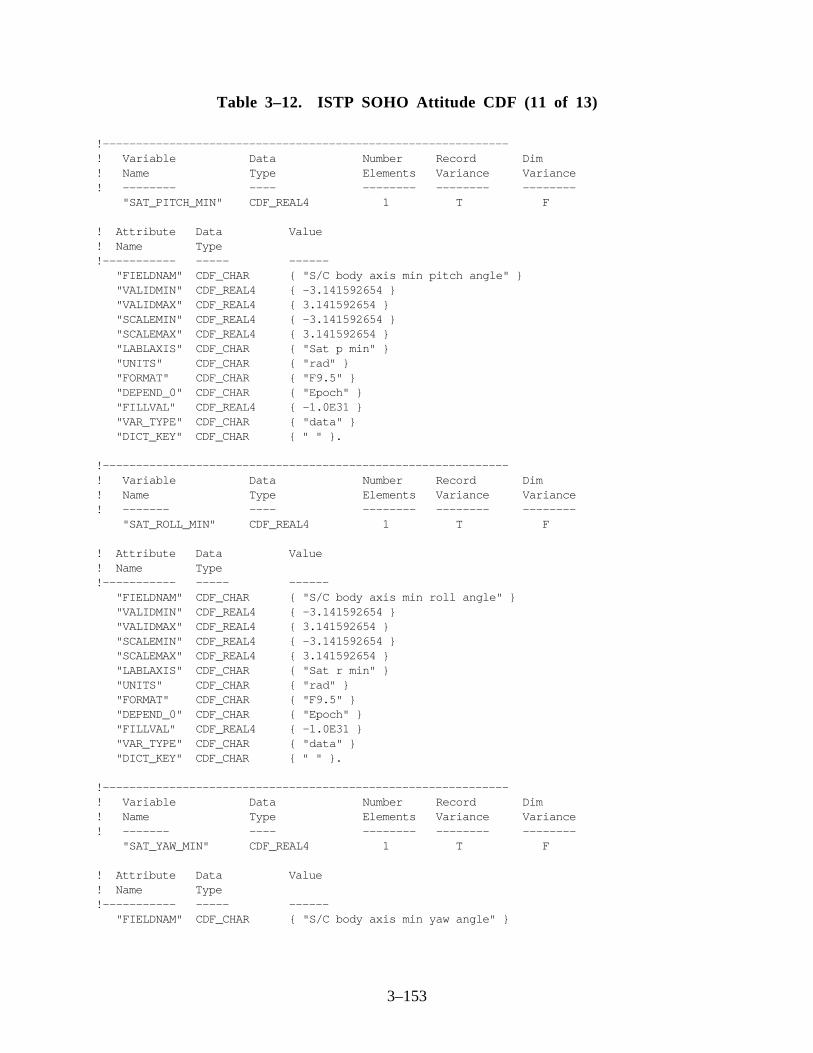
3–153
Table 3–12. ISTP SOHO Attitude CDF (11 of 13)
!-------------------------------------------------------------! Variable Data Number Record Dim! Name Type Elements Variance Variance! -------- ---- -------- -------- -------- "SAT_PITCH_MIN" CDF_REAL4 1 T F
! Attribute Data Value! Name Type!----------- ----- ------ "FIELDNAM" CDF_CHAR { "S/C body axis min pitch angle" } "VALIDMIN" CDF_REAL4 { -3.141592654 } "VALIDMAX" CDF_REAL4 { 3.141592654 } "SCALEMIN" CDF_REAL4 { -3.141592654 } "SCALEMAX" CDF_REAL4 { 3.141592654 } "LABLAXIS" CDF_CHAR { "Sat p min" } "UNITS" CDF_CHAR { "rad" } "FORMAT" CDF_CHAR { "F9.5" } "DEPEND_0" CDF_CHAR { "Epoch" } "FILLVAL" CDF_REAL4 { -1.0E31 } "VAR_TYPE" CDF_CHAR { "data" } "DICT_KEY" CDF_CHAR { " " }.
!-------------------------------------------------------------! Variable Data Number Record Dim! Name Type Elements Variance Variance! ------- ---- -------- -------- -------- "SAT_ROLL_MIN" CDF_REAL4 1 T F
! Attribute Data Value! Name Type!----------- ----- ------ "FIELDNAM" CDF_CHAR { "S/C body axis min roll angle" } "VALIDMIN" CDF_REAL4 { -3.141592654 } "VALIDMAX" CDF_REAL4 { 3.141592654 } "SCALEMIN" CDF_REAL4 { -3.141592654 } "SCALEMAX" CDF_REAL4 { 3.141592654 } "LABLAXIS" CDF_CHAR { "Sat r min" } "UNITS" CDF_CHAR { "rad" } "FORMAT" CDF_CHAR { "F9.5" } "DEPEND_0" CDF_CHAR { "Epoch" } "FILLVAL" CDF_REAL4 { -1.0E31 } "VAR_TYPE" CDF_CHAR { "data" } "DICT_KEY" CDF_CHAR { " " }.
!-------------------------------------------------------------! Variable Data Number Record Dim! Name Type Elements Variance Variance! ------- ---- -------- -------- -------- "SAT_YAW_MIN" CDF_REAL4 1 T F
! Attribute Data Value! Name Type!----------- ----- ------ "FIELDNAM" CDF_CHAR { "S/C body axis min yaw angle" }

3–154
Table 3–12. ISTP SOHO Attitude CDF (12 of 13)
"VALIDMIN" CDF_REAL4 { -1.570796327 } "VALIDMAX" CDF_REAL4 { 1.570796327 } "SCALEMIN" CDF_REAL4 { -1.570796327 } "SCALEMAX" CDF_REAL4 { 1.570796327 } "LABLAXIS" CDF_CHAR { "Sat y min" } "UNITS" CDF_CHAR { "rad" } "FORMAT" CDF_CHAR { "F9.5" } "DEPEND_0" CDF_CHAR { "Epoch" } "FILLVAL" CDF_REAL4 { -1.0E31 } "VAR_TYPE" CDF_CHAR { "data" } "DICT_KEY" CDF_CHAR { " " }.
!-------------------------------------------------------------! Variable Data Number Record Dim! Name Type Elements Variance Variance! -------- ---- -------- -------- -------- "SAT_PITCH_MAX" CDF_REAL4 1 T F
! Attribute Data Value! Name Type!----------- ----- ------ "FIELDNAM" CDF_CHAR { "S/C body axis max pitch angle" } "VALIDMIN" CDF_REAL4 { -3.141592654 } "VALIDMAX" CDF_REAL4 { 3.141592654 } "SCALEMIN" CDF_REAL4 { -3.141592654 } "SCALEMAX" CDF_REAL4 { 3.141592654 } "LABLAXIS" CDF_CHAR { "Sat p max" } "UNITS" CDF_CHAR { "rad" } "FORMAT" CDF_CHAR { "F9.5" } "DEPEND_0" CDF_CHAR { "Epoch" } "FILLVAL" CDF_REAL4 { -1.0E31 } "VAR_TYPE" CDF_CHAR { "data" } "DICT_KEY" CDF_CHAR { " " }.
!-------------------------------------------------------------! Variable Data Number Record Dim! Name Type Elements Variance Variance! ------- ---- -------- -------- -------- "SAT_ROLL_MAX" CDF_REAL4 1 T F
! Attribute Data Value! Name Type!----------- ----- ------ "FIELDNAM" CDF_CHAR { "S/C body axis max roll angle" } "VALIDMIN" CDF_REAL4 { -3.141592654 } "VALIDMAX" CDF_REAL4 { 3.141592654 } "SCALEMIN" CDF_REAL4 { -3.141592654 } "SCALEMAX" CDF_REAL4 { 3.141592654 } "LABLAXIS" CDF_CHAR { "Sat r max" } "UNITS" CDF_CHAR { "rad" }

3–155
Table 3–12. ISTP SOHO Attitude CDF (13 of 13)
"FORMAT" CDF_CHAR { "F9.5" } "DEPEND_0" CDF_CHAR { "Epoch" } "FILLVAL" CDF_REAL4 { -1.0E31 } "VAR_TYPE" CDF_CHAR { "data" } "DICT_KEY" CDF_CHAR { " " }.
!-------------------------------------------------------------! Variable Data Number Record Dim! Name Type Elements Variance Variance! ------- ---- -------- -------- -------- "SAT_YAW_MAX" CDF_REAL4 1 T F
! Attribute Data Value! Name Type!----------- ----- ------ "FIELDNAM" CDF_CHAR { "S/C body axis max yaw angle" } "VALIDMIN" CDF_REAL4 { -1.570796327 } "VALIDMAX" CDF_REAL4 { 1.570796327 } "SCALEMIN" CDF_REAL4 { -1.570796327 } "SCALEMAX" CDF_REAL4 { 1.570796327 } "LABLAXIS" CDF_CHAR { "Sat y max" } "UNITS" CDF_CHAR { "rad" } "FORMAT" CDF_CHAR { "F9.5" } "DEPEND_0" CDF_CHAR { "Epoch" } "FILLVAL" CDF_REAL4 { -1.0E31 } "VAR_TYPE" CDF_CHAR { "data" } "DICT_KEY" CDF_CHAR { " " }.
!-------------------------------------------------------------
#end

3–156
Table 3–13. ISTP POLAR Despun Platform Attitude CDF (1 of 9)
#header
! SKELETON TABLE FOR THE ISTP DESPUN PLATFORM ATTITUDE CDF
CDF NAME : istp_despun_platform_attitude DATA ENCODING : NETWORK MAJORITY : COLUMN FORMAT : SINGLE
! Variables G. Attributes V.Attributes Records Dims Sizes! --------- ------------- ------------- ------- --- ----- 18 19 17 0 1 3
!-------------------------------------------------------------#GLOBALattributes
! Attribute Entry Data Value! Name Number Type! --------- ------ ---- ----- "TITLE" 1: CDF_CHAR {"ISTP despun platform " - "attitude CDF"}. "Project" 1: CDF_CHAR {"ISTP>International " - "Solar-Terrestrial Physics"}. "Discipline" 1: CDF_CHAR {"Space Physics"}. "Source_name" 1: CDF_CHAR {"POLAR>Polar Plasma " - "Laboratory"}. "Data_version" 1: CDF_CHAR {" "}. "Data_type" 1: CDF_CHAR {"PA>Platform Attitude"}. "Descriptor" 1: CDF_CHAR {"DEF>Definitive data"}. "STABILIZATION_TYPE" 1: CDF_CHAR {"D"}. "ROTATION_SEQUENCE" 1: CDF_CHAR {"ZYZ"}. "MISALIGN_ANG_1" 1: CDF_CHAR {" "}. "MISALIGN_ANG_2" 1: CDF_CHAR {" "}. "MISALIGN_ANG_3" 1: CDF_CHAR {" "}. "START_DATE" 1: CDF_CHAR {" "}. "END_DATE" 1: CDF_CHAR {" "}. "STEP_SIZE" 1: CDF_CHAR {" "}. "ADID_ref" 1: CDF_CHAR {"NSSD0156"}. "Logical_file_id" 1: CDF_CHAR {" "}. "TEXT" 1: CDF_CHAR {"Based on the FDF DPA " - "algorithm"}. "MODS" 1: CDF_CHAR {"6/11/93 - Original " - "Implementation"} 2: CDF_CHAR {"4/1/94 - Modified VALIDMIN " - "and VALIDMAX for ORB_ROLL, "} 3: CDF_CHAR {"ORB_YAW, GCI_ROLL, GCI_YAW, " - "GSE_ROLL, GSE_YAW, GSM_ROLL, " - "and GSM_YAW"} 4: CDF_CHAR {"6/7/94 - CCR ISTP 1852, " - "updated CDHF skeleton to " - "CDF standards - JT"} 5: CDF_CHAR {"11/9/94 - Correct errors " - "made in ccr 1852. ICCR 1884"}.

3–157
Table 3–13. ISTP POLAR Despun Platform Attitude CDF (2 of 9)
!-------------------------------------------------------------#VARIABLEattributes
"FIELDNAM" "VALIDMIN" "VALIDMAX" "SCALEMIN" "SCALEMAX" "LABLAXIS" "UNITS" "FORMAT" "LABL_PTR_1" "UNIT_PTR" "FORM_PTR" "MONOTON" "DEPEND_0" "DEPEND_1" "FILLVAL" "VAR_TYPE" "DICT_KEY"
!-------------------------------------------------------------#variables
! Variable Data Number Record Dim! Name Type Elements Variance Variance! ------- ---- -------- -------- -------- "Epoch" CDF_EPOCH 1 T F
! Attribute Data Value! Name Type!----------- ----- ------ "FIELDNAM" CDF_CHAR { "DP attitude EPOCH time" } "VALIDMIN" CDF_EPOCH { 01-JUL-1992 00:00:00.000 } "VALIDMAX" CDF_EPOCH { 31-DEC-2020 23:59:59.000 } "SCALEMIN" CDF_EPOCH { 01-JUL-1992 00:00:00.000 } "SCALEMAX" CDF_EPOCH { 31-DEC-2020 23:59:59.000 } "LABLAXIS" CDF_CHAR { "Epoch" } "UNITS" CDF_CHAR { "ms" } "MONOTON" CDF_CHAR { "INCREASE" } "FILLVAL" CDF_REAL8 { -1.0E31 } "VAR_TYPE" CDF_CHAR { "data" } "DICT_KEY" CDF_CHAR { " " }.
!-------------------------------------------------------------! Variable Data Number Record Dim! Name Type Elements Variance Variance! ------- ---- -------- -------- -------- "Time_PB5" CDF_INT4 1 T T
! Attribute Data Value! Name Type!----------- ----- ------ "FIELDNAM" CDF_CHAR { "DP attitude PB5 time" }

3–158
Table 3–13. ISTP POLAR Despun Platform Attitude CDF (3 of 9)
"SCALEMIN" CDF_INT4 { 1992, 183, 0 } "SCALEMAX" CDF_INT4 { 2020, 366, 86399000 } "LABL_PTR_1" CDF_CHAR { "label_time" } "UNIT_PTR" CDF_CHAR { "unit_time" } "FORM_PTR" CDF_CHAR { "format_time" } "DEPEND_0" CDF_CHAR { "Epoch" } "DEPEND_1" CDF_CHAR { "unit_time" } "FILLVAL" CDF_INT4 { -2147483648 } "VAR_TYPE" CDF_CHAR { "data" } "DICT_KEY" CDF_CHAR { " " }.
!-------------------------------------------------------------! Variable Data Number Record Dim! Name Type Elements Variance Variance! ------- ---- -------- -------- -------- "label_time" CDF_CHAR 27 F T
! Attribute Data Value! Name Type "VALIDMIN" CDF_INT4 { 1992, 183, 0 } "VALIDMAX" CDF_INT4 { 2020, 366, 86399000 }!----------- ----- ------ "FIELDNAM" CDF_CHAR { "Label for Time_PB5" } "VAR_TYPE" CDF_CHAR { "metadata" } "DICT_KEY" CDF_CHAR { " " }.
[1] = { "Year " } [2] = { "Day of Year (Jan 1 = day 1)" } [3] = { "Elapsed ms of Day " }
!-------------------------------------------------------------! Variable Data Number Record Dim! Name Type Elements Variance Variance! ------- ---- -------- -------- -------- "unit_time" CDF_CHAR 4 F T
! Attribute Data Value! Name Type!----------- ----- ------ "FIELDNAM" CDF_CHAR { "Units for Time_PB5" } "VAR_TYPE" CDF_CHAR { "metadata" } "DICT_KEY" CDF_CHAR { " " }.
[1] = { "year" } [2] = { "day " } [3] = { "msec" }
!-------------------------------------------------------------! Variable Data Number Record Dim! Name Type Elements Variance Variance! ------- ---- -------- -------- -------- "format_time" CDF_CHAR 2 F T

3–159
Table 3–13. ISTP POLAR Despun Platform Attitude CDF (4 of 9)
! Attribute Data Value! Name Type!----------- ----- ------ "FIELDNAM" CDF_CHAR { "Formats for Time_PB5" } "VAR_TYPE" CDF_CHAR { "metadata" } "DICT_KEY" CDF_CHAR { " " }.
[1] = { "I4" } [2] = { "I3" } [3] = { "I8" }
!-------------------------------------------------------------! Variable Data Number Record Dim! Name Type Elements Variance Variance! -------- ---- -------- -------- -------- "ORB_PITCH" CDF_REAL4 1 T F
! Attribute Data Value! Name Type!----------- ----- ------ "FIELDNAM" CDF_CHAR { "Orbital pitch angle" } "VALIDMIN" CDF_REAL4 { -3.141592654 }
"VALIDMAX" CDF_REAL4 { 3.141592654 } "SCALEMIN" CDF_REAL4 { -3.141592654 } "SCALEMAX" CDF_REAL4 { 3.141592654 } "LABLAXIS" CDF_CHAR { "Orb Pitch" } "UNITS" CDF_CHAR { "rad" } "FORMAT" CDF_CHAR { "F9.5" } "DEPEND_0" CDF_CHAR { "Epoch" } "FILLVAL" CDF_REAL4 { -1.0E31 } "VAR_TYPE" CDF_CHAR { "data" } "DICT_KEY" CDF_CHAR { " "}.
!-------------------------------------------------------------! Variable Data Number Record Dim! Name Type Elements Variance Variance! ------- ---- -------- -------- -------- "ORB_ROLL" CDF_REAL4 1 T F
! Attribute Data Value! Name Type!----------- ----- ------ "FIELDNAM" CDF_CHAR { "Orbital roll angle" } "VALIDMIN" CDF_REAL4 { -3.141592654 } "VALIDMAX" CDF_REAL4 { 3.141592654 } "SCALEMIN" CDF_REAL4 { -3.141592654 } "SCALEMAX" CDF_REAL4 { 3.141592654 } "LABLAXIS" CDF_CHAR { "Orb Roll" } "UNITS" CDF_CHAR { "rad" } "FORMAT" CDF_CHAR { "F9.5" } "DEPEND_0" CDF_CHAR { "Epoch" } "FILLVAL" CDF_REAL4 { -1.0E31 } "VAR_TYPE" CDF_CHAR { "data" }

3–160
Table 3–13. ISTP POLAR Despun Platform Attitude CDF (5 of 9)
"DICT_KEY" CDF_CHAR { " " }.
!-------------------------------------------------------------! Variable Data Number Record Dim! Name Type Elements Variance Variance! ------- ---- -------- -------- -------- "ORB_YAW" CDF_REAL4 1 T F
! Attribute Data Value! Name Type!----------- ----- ------ "FIELDNAM" CDF_CHAR { "Orbital yaw angle" } "VALIDMIN" CDF_REAL4 { -1.570796327 } "VALIDMAX" CDF_REAL4 { 1.570796327 } "SCALEMIN" CDF_REAL4 { -1.570796327 } "SCALEMAX" CDF_REAL4 { 1.570796327 } "LABLAXIS" CDF_CHAR { "Orb Yaw" } "UNITS" CDF_CHAR { "rad" } "FORMAT" CDF_CHAR { "F9.5" } "DEPEND_0" CDF_CHAR { "Epoch" } "FILLVAL" CDF_REAL4 { -1.0E31 } "VAR_TYPE" CDF_CHAR { "data" } "DICT_KEY" CDF_CHAR { " " }.!-------------------------------------------------------------! Variable Data Number Record Dim! Name Type Elements Variance Variance! -------- ---- -------- -------- -------- "GCI_PITCH" CDF_REAL4 1 T F
! Attribute Data Value! Name Type!----------- ----- ------ "FIELDNAM" CDF_CHAR { "GCI pitch angle" } "VALIDMIN" CDF_REAL4 { -3.141592654 } "VALIDMAX" CDF_REAL4 { 3.141592654 } "SCALEMIN" CDF_REAL4 { -3.141592654 } "SCALEMAX" CDF_REAL4 { 3.141592654 } "LABLAXIS" CDF_CHAR { "GCI Pitch" } "UNITS" CDF_CHAR { "rad" } "FORMAT" CDF_CHAR { "F9.5" } "DEPEND_0" CDF_CHAR { "Epoch" } "FILLVAL" CDF_REAL4 { -1.0E31 } "VAR_TYPE" CDF_CHAR { "data" } "DICT_KEY" CDF_CHAR { " " }.
!-------------------------------------------------------------! Variable Data Number Record Dim! Name Type Elements Variance Variance! ------- ---- -------- -------- -------- "GCI_ROLL" CDF_REAL4 1 T F
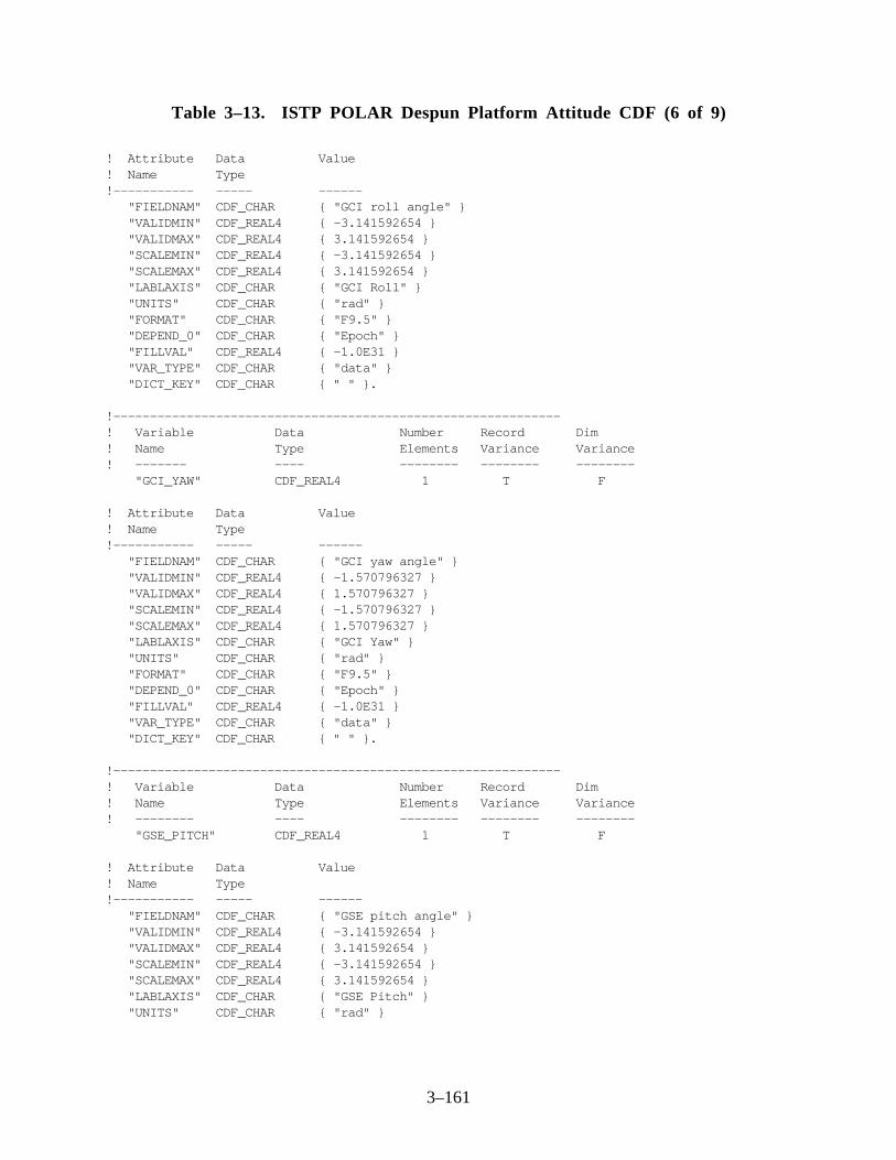
3–161
Table 3–13. ISTP POLAR Despun Platform Attitude CDF (6 of 9)
! Attribute Data Value! Name Type!----------- ----- ------ "FIELDNAM" CDF_CHAR { "GCI roll angle" } "VALIDMIN" CDF_REAL4 { -3.141592654 } "VALIDMAX" CDF_REAL4 { 3.141592654 } "SCALEMIN" CDF_REAL4 { -3.141592654 } "SCALEMAX" CDF_REAL4 { 3.141592654 } "LABLAXIS" CDF_CHAR { "GCI Roll" } "UNITS" CDF_CHAR { "rad" } "FORMAT" CDF_CHAR { "F9.5" } "DEPEND_0" CDF_CHAR { "Epoch" } "FILLVAL" CDF_REAL4 { -1.0E31 } "VAR_TYPE" CDF_CHAR { "data" } "DICT_KEY" CDF_CHAR { " " }.
!-------------------------------------------------------------! Variable Data Number Record Dim! Name Type Elements Variance Variance! ------- ---- -------- -------- -------- "GCI_YAW" CDF_REAL4 1 T F
! Attribute Data Value! Name Type!----------- ----- ------ "FIELDNAM" CDF_CHAR { "GCI yaw angle" } "VALIDMIN" CDF_REAL4 { -1.570796327 } "VALIDMAX" CDF_REAL4 { 1.570796327 } "SCALEMIN" CDF_REAL4 { -1.570796327 } "SCALEMAX" CDF_REAL4 { 1.570796327 } "LABLAXIS" CDF_CHAR { "GCI Yaw" } "UNITS" CDF_CHAR { "rad" } "FORMAT" CDF_CHAR { "F9.5" } "DEPEND_0" CDF_CHAR { "Epoch" } "FILLVAL" CDF_REAL4 { -1.0E31 } "VAR_TYPE" CDF_CHAR { "data" } "DICT_KEY" CDF_CHAR { " " }.
!-------------------------------------------------------------! Variable Data Number Record Dim! Name Type Elements Variance Variance! -------- ---- -------- -------- -------- "GSE_PITCH" CDF_REAL4 1 T F
! Attribute Data Value! Name Type!----------- ----- ------ "FIELDNAM" CDF_CHAR { "GSE pitch angle" } "VALIDMIN" CDF_REAL4 { -3.141592654 } "VALIDMAX" CDF_REAL4 { 3.141592654 } "SCALEMIN" CDF_REAL4 { -3.141592654 } "SCALEMAX" CDF_REAL4 { 3.141592654 } "LABLAXIS" CDF_CHAR { "GSE Pitch" } "UNITS" CDF_CHAR { "rad" }

3–162
Table 3–13. ISTP POLAR Despun Platform Attitude CDF (7 of 9)
"FORMAT" CDF_CHAR { "F9.5" } "DEPEND_0" CDF_CHAR { "Epoch" } "FILLVAL" CDF_REAL4 { -1.0E31 } "VAR_TYPE" CDF_CHAR { "data" } "DICT_KEY" CDF_CHAR { " " }.
!-------------------------------------------------------------! Variable Data Number Record Dim! Name Type Elements Variance Variance! ------- ---- -------- -------- -------- "GSE_ROLL" CDF_REAL4 1 T F
! Attribute Data Value! Name Type!----------- ----- ------ "FIELDNAM" CDF_CHAR { "GSE roll angle" } "VALIDMIN" CDF_REAL4 { -3.141592654 } "VALIDMAX" CDF_REAL4 { 3.141592654 } "SCALEMIN" CDF_REAL4 { -3.141592654 } "SCALEMAX" CDF_REAL4 { 3.141592654 } "LABLAXIS" CDF_CHAR { "GSE Roll" } "UNITS" CDF_CHAR { "rad" } "FORMAT" CDF_CHAR { "F9.5" } "DEPEND_0" CDF_CHAR { "Epoch" } "FILLVAL" CDF_REAL4 { -1.0E31 } "VAR_TYPE" CDF_CHAR { "data" } "DICT_KEY" CDF_CHAR { " " }.
!-------------------------------------------------------------! Variable Data Number Record Dim! Name Type Elements Variance Variance! -------- ---- -------- -------- -------- "GSE_YAW" CDF_REAL4 1 T F
! Attribute Data Value! Name Type!----------- ----- ------ "FIELDNAM" CDF_CHAR { "GSE yaw angle" } "VALIDMIN" CDF_REAL4 { -1.570796327 } "VALIDMAX" CDF_REAL4 { 1.570796327 } "SCALEMIN" CDF_REAL4 { -1.570796327 } "SCALEMAX" CDF_REAL4 { 1.570796327 } "LABLAXIS" CDF_CHAR { "GSE Yaw" } "UNITS" CDF_CHAR { "rad" } "FORMAT" CDF_CHAR { "F9.5" } "DEPEND_0" CDF_CHAR { "Epoch" } "FILLVAL" CDF_REAL4 { -1.0E31 } "VAR_TYPE" CDF_CHAR { "data" } "DICT_KEY" CDF_CHAR { " " }.

3–163
Table 3–13. ISTP POLAR Despun Platform Attitude CDF (8 of 9)
!-------------------------------------------------------------! Variable Data Number Record Dim! Name Type Elements Variance Variance! -------- ---- -------- -------- -------- "GSM_PITCH" CDF_REAL4 1 T F
! Attribute Data Value! Name Type!----------- ----- ------ "FIELDNAM" CDF_CHAR { "GSM pitch angle" } "VALIDMIN" CDF_REAL4 { -3.141592654 } "VALIDMAX" CDF_REAL4 { 3.141592654 } "SCALEMIN" CDF_REAL4 { -3.141592654 } "SCALEMAX" CDF_REAL4 { 3.141592654 } "LABLAXIS" CDF_CHAR { "GSM Pitch" } "UNITS" CDF_CHAR { "rad" } "FORMAT" CDF_CHAR { "F9.5" } "DEPEND_0" CDF_CHAR { "Epoch" } "FILLVAL" CDF_REAL4 { -1.0E31 } "VAR_TYPE" CDF_CHAR { "data" } "DICT_KEY" CDF_CHAR { " " }.
!-------------------------------------------------------------! Variable Data Number Record Dim! Name Type Elements Variance Variance! ------- ---- -------- -------- -------- "GSM_ROLL" CDF_REAL4 1 T F
! Attribute Data Value! Name Type!----------- ----- ------ "FIELDNAM" CDF_CHAR { "GSM roll angle" } "VALIDMIN" CDF_REAL4 { -3.141592654 } "VALIDMAX" CDF_REAL4 { 3.141592654 } "SCALEMIN" CDF_REAL4 { -3.141592654 } "SCALEMAX" CDF_REAL4 { 3.141592654 } "LABLAXIS" CDF_CHAR { "GSM Roll" } "UNITS" CDF_CHAR { "rad" } "FORMAT" CDF_CHAR { "F9.5" } "DEPEND_0" CDF_CHAR { "Epoch" } "FILLVAL" CDF_REAL4 { -1.0E31 } "VAR_TYPE" CDF_CHAR { "data" } "DICT_KEY" CDF_CHAR { " " }.
!-------------------------------------------------------------! Variable Data Number Record Dim! Name Type Elements Variance Variance! -------- ---- -------- -------- -------- "GSM_YAW" CDF_REAL4 1 T F

3–164
Table 3–13. ISTP POLAR Despun Platform Attitude CDF (9 of 9)
! Attribute Data Value! Name Type!----------- ----- ------ "FIELDNAM" CDF_CHAR { "GSM yaw angle" } "VALIDMIN" CDF_REAL4 { -1.570796327 } "VALIDMAX" CDF_REAL4 { 1.570796327 } "SCALEMIN" CDF_REAL4 { -1.570796327 } "SCALEMAX" CDF_REAL4 { 1.570796327 } "LABLAXIS" CDF_CHAR { "GSM Yaw" } "UNITS" CDF_CHAR { "rad" } "FORMAT" CDF_CHAR { "F9.5" } "DEPEND_0" CDF_CHAR { "Epoch" } "FILLVAL" CDF_REAL4 { -1.0E31 } "VAR_TYPE" CDF_CHAR { "data" } "DICT_KEY" CDF_CHAR { " " }.
!-------------------------------------------------------------! Variable Data Number Record Dim! Name Type Elements Variance Variance! -------- ---- -------- -------- -------- "DPA_INDICATOR" CDF_INT4 1 T F
! Attribute Data Value! Name Type!----------- ----- ------ "FIELDNAM" CDF_CHAR { "DPA accuracy indicator" } "VALIDMIN" CDF_INT4 { 0 } "VALIDMAX" CDF_INT4 { 1 } "SCALEMIN" CDF_INT4 { 0 } "SCALEMAX" CDF_INT4 { 1 } "LABLAXIS" CDF_CHAR { "DPA Ind" } "UNITS" CDF_CHAR { " " } "FORMAT" CDF_CHAR { "I1" } "DEPEND_0" CDF_CHAR { "Epoch" }
"FILLVAL" CDF_INT4 { -2147483648 } "VAR_TYPE" CDF_CHAR { "data" } "DICT_KEY" CDF_CHAR { " " }.
!-------------------------------------------------------------#end

3–165
3 .8 SOHO Full-Time Resolution Attitude
In addition to the standard CDF attitude file, the CDHF will extract the full-time resolution datafrom the SOHO telemetry and create a new attitude file for distribution to the SOHO investigators.The roll angle data will be repeated to fill in to match the 10 values per second of pitch and yawdata. The full-time resolution file will contain IEEE records at 10 samples per second. As shown inTable 3–14 and 3-14a, the file will contain the following fields in spacecraft body-axis coordinates:
Year, Day of Year, Millisecond of Day, Pitch Angle, Yaw Angle, Roll Angle, SunPresent Flag, and Validity Flag
The Sun present flag and the validity flag match the corresponding flags in the telemetry datastream. An example filename for a SOHO full-resolution file is as follows:
SO_AT_FTR_19940915_V01.TXT
Note that the file-naming convention is described in detail in Section 2.6.
Table 3–14. SOHO Full-Time Resolution Attitude Data Record Format
Field Bytes Type Length Description1 0–3 Integer 4 Year2 4–7 Integer 4 Day of Year
Table 3–14a. SOHO Full-Time Resolution Attitude Header Record Format
Field Bytes Type Length Description1 0–3 Integer 4 Milliseconds of Day2 4–7 Real 4 Pitch Angle (Degrees)3 4–11 Real 4 Yaw Angle (Degrees)4 12–15 Real 4 Roll Angle (Degrees)5 16–19 Integer 4 Data Flag: Sum of sun flag (0 = present, 1 = not
present) times 10 + validity flag (0 = valid data, 1=invalid data)
3 .9 GEOTAIL Spin-Phase Format
ISTP GEOTAIL spin-phase files are provided in CDF; Reference 3 provides information onextracting spin-phase data from CDF. Table 3–15 presents the CDF skeleton table for theGEOTAIL spin-phase data.

3–166
3.10 WIND and POLAR Spin-Phase Format
ISTP WIND and POLAR spin-phase files are provided in CDF; Reference 3 provides informationon extracting spin-phase data from CDF. Table 3–16 presents the CDF skeleton table for theWIND and POLAR spin-phase data.
Table 3–15. ISTP GEOTAIL Spin-Phase CDF (1 of 4)#header! SKELETON TABLE FOR THE ISTP GEOTAIL SPIN PHASE CDF CDF NAME : istp_geotail_spin_phase DATA ENCODING : NETWORK MAJORITY : COLUMN FORMAT : SINGLE! Variables G. Attributes V.Attributes Records Dims Sizes! --------- ------------- ------------ ------- ---- ----- 8 14 17 0 1 3!-------------------------------------------------------------#GLOBALattributes! Attribute Entry Data Value! Name Number Type! --------- ------ ---- ----- "TITLE" 1: CDF_CHAR {"ISTP GEOTAIL spin phase CDF"}. "Project" 1: CDF_CHAR {"ISTP>International " - "Solar-Terrestrial Physics"}. "Discipline" 1: CDF_CHAR {"Space Physics"}. "Source_name" 1: CDF_CHAR {"GEOTAIL>Geomagnetic Tail"}. "Data_version" 1: CDF_CHAR {" "}. "Data_type" 1: CDF_CHAR {"K0>Key Parameter"}. "Descriptor" 1: CDF_CHAR {"SPHA>Spin Phase"}. "ADID_ref" 1: CDF_CHAR {"NSSD0133"}. "Logical_file_id" 1: CDF_CHAR {" "}. "START_DATE" 1: CDF_CHAR {" "}. "END_DATE" 1: CDF_CHAR {" "}. "STEP_SIZE" 1: CDF_CHAR {"60000"}. "TEXT" 1: CDF_CHAR {"Geotail Prelaunch Report " - "April 1992"}. "MODS" 1: CDF_CHAR {"4/6/92 - Original " - "Implementation, CCR 935"} 2: CDF_CHAR {"6/12/92 - Added global " - "attributes TITLE, PROJECT, "} 3: CDF_CHAR {"DISCIPLINE, SOURCE_NAME, " - "DATA_VERSION, and MODS;"} 4: CDF_CHAR {"added variable attributes " - "VALIDMIN, VALIDMAX, " - "LABL_PTR_1, and MONOTON;"} 5: CDF_CHAR {"added variables EPOCH and " - "LABEL_TIME; "} 6: CDF_CHAR {"changed variable name " - "TIME to TIME_PB5. CCR 935"} 7: CDF_CHAR {"9/23/92 - Changed descriptor" - " value from SPAH to SPHA. " - "ICCR 1387"} 8: CDF_CHAR {"2/22/93 - Changed VALIDMAX " - "of FAULT. CCR 1361"} 9: CDF_CHAR {"6/10/93 - Added ADID_ref " - "and Logical_file_id. " - "CCR 1092"} 10: CDF_CHAR {"6/14/94 - CCR ISTP 1852, " - "updated CDHF skeleton to " -

3–167
Table 3–15. ISTP GEOTAIL Spin-Phase CDF (2 of 4)
"CDF standards - JT"} 11: CDF_CHAR {"11/9/94 - Correct errors " - "made in ccr 1852. ICCR 1884"}.!-------------------------------------------------------------#VARIABLEattributes "FIELDNAM" "VALIDMIN" "VALIDMAX" "SCALEMIN" "SCALEMAX" "LABLAXIS" "UNITS" "FORMAT" "LABL_PTR_1" "UNIT_PTR" "FORM_PTR" "MONOTON" "DEPEND_0" "DEPEND_1" "FILLVAL" "VAR_TYPE" "DICT_KEY"!-------------------------------------------------------------#variables! Variable Data Number Record Dim! Name Type Elements Variance Variance! ------- ---- -------- -------- -------- "Epoch" CDF_EPOCH 1 T F! Attribute Data Value! Name Type!----------- ----- ------ "FIELDNAM" CDF_CHAR { "Spin phase EPOCH time" } "VALIDMIN" CDF_EPOCH { 01-JUL-1992 00:00:00.000 } "VALIDMAX" CDF_EPOCH { 31-DEC-2020 23:59:59.000 } "SCALEMIN" CDF_EPOCH { 01-JUL-1992 00:00:00.000 } "SCALEMAX" CDF_EPOCH { 31-DEC-2020 23:59:59.000 } "LABLAXIS" CDF_CHAR { "Epoch" } "UNITS" CDF_CHAR { "ms" } "MONOTON" CDF_CHAR { "INCREASE" } "FILLVAL" CDF_REAL8 { -1.0E31 } "VAR_TYPE" CDF_CHAR { "data" } "DICT_KEY" CDF_CHAR { " " }.!-------------------------------------------------------------! Variable Data Number Record Dim! Name Type Elements Variance Variance! ------- ---- -------- -------- -------- "Time_PB5" CDF_INT4 1 T T! Attribute Data Value! Name Type!----------- ----- ------ "FIELDNAM" CDF_CHAR { "Spin phase PB5 time" } "VALIDMIN" CDF_INT4 { 1992, 183, 0 } "VALIDMAX" CDF_INT4 { 2020, 366, 86399000 } "SCALEMIN" CDF_INT4 { 1992, 183, 0 } "SCALEMAX" CDF_INT4 { 2020, 366, 86399000 } "LABL_PTR_1" CDF_CHAR { "label_time" } "UNIT_PTR" CDF_CHAR { "unit_time" } "FORM_PTR" CDF_CHAR { "format_time" } "DEPEND_0" CDF_CHAR { "Epoch" } "DEPEND_1" CDF_CHAR { "unit_time" }
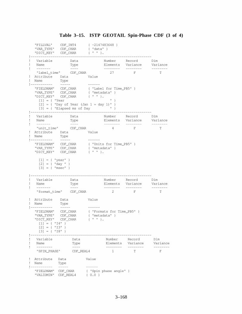
3–168
Table 3–15. ISTP GEOTAIL Spin-Phase CDF (3 of 4)
"FILLVAL" CDF_INT4 { -2147483648 } "VAR_TYPE" CDF_CHAR { "data" } "DICT_KEY" CDF_CHAR { " " }.!-------------------------------------------------------------! Variable Data Number Record Dim! Name Type Elements Variance Variance! ------- ---- -------- -------- -------- "label_time" CDF_CHAR 27 F T! Attribute Data Value! Name Type!----------- ----- ------ "FIELDNAM" CDF_CHAR { "Label for Time_PB5" } "VAR_TYPE" CDF_CHAR { "metadata" } "DICT_KEY" CDF_CHAR { " " }. [1] = { "Year " } [2] = { "Day of Year (Jan 1 = day 1)" } [3] = { "Elapsed ms of Day " }!-------------------------------------------------------------! Variable Data Number Record Dim! Name Type Elements Variance Variance! ------- ---- -------- -------- -------- "unit_time" CDF_CHAR 4 F T! Attribute Data Value! Name Type!----------- ----- ------ "FIELDNAM" CDF_CHAR { "Units for Time_PB5" } "VAR_TYPE" CDF_CHAR { "metadata" } "DICT_KEY" CDF_CHAR { " " }.
[1] = { "year" } [2] = { "day " } [3] = { "msec" }
!-------------------------------------------------------------! Variable Data Number Record Dim! Name Type Elements Variance Variance! ------- ---- -------- -------- -------- "format_time" CDF_CHAR 2 F T
! Attribute Data Value! Name Type!----------- ----- ------ "FIELDNAM" CDF_CHAR { "Formats for Time_PB5" } "VAR_TYPE" CDF_CHAR { "metadata" } "DICT_KEY" CDF_CHAR { " " }. [1] = { "I4" } [2] = { "I3" } [3] = { "I8" }!-------------------------------------------------------------! Variable Data Number Record Dim! Name Type Elements Variance Variance! -------- ---- -------- -------- -------- "SPIN_PHASE" CDF_REAL4 1 T F
! Attribute Data Value! Name Type!----------- ----- ------ "FIELDNAM" CDF_CHAR { "Spin phase angle" } "VALIDMIN" CDF_REAL4 { 0.0 }

3–169
Table 3–15. ISTP GEOTAIL Spin-Phase CDF (4 of 4)
"VALIDMAX" CDF_REAL4 { 6.283185307 } "SCALEMIN" CDF_REAL4 { 0.0 } "SCALEMAX" CDF_REAL4 { 6.283185307 } "LABLAXIS" CDF_CHAR { "SP Angle" } "UNITS" CDF_CHAR { "rad" } "FORMAT" CDF_CHAR { "F12.8" } "DEPEND_0" CDF_CHAR { "Epoch" } "FILLVAL" CDF_REAL4 { -1.0E31 } "VAR_TYPE" CDF_CHAR { "data" } "DICT_KEY" CDF_CHAR { " " }.
!-------------------------------------------------------------! Variable Data Number Record Dim! Name Type Elements Variance Variance! -------- ---- -------- -------- -------- "SPIN_RATE" CDF_REAL4 1 T F
! Attribute Data Value! Name Type!----------- ----- ------ "FIELDNAM" CDF_CHAR { "Spin rate" } "VALIDMIN" CDF_REAL4 { 0.0 } "VALIDMAX" CDF_REAL4 { 6.283185307 } "SCALEMIN" CDF_REAL4 { 0.0 } "SCALEMAX" CDF_REAL4 { 6.283185307 } "LABLAXIS" CDF_CHAR { "Spin Rate" } "UNITS" CDF_CHAR { "rad/sec" } "FORMAT" CDF_CHAR { "F12.8" } "DEPEND_0" CDF_CHAR { "Epoch" } "FILLVAL" CDF_REAL4 { -1.0E31 } "VAR_TYPE" CDF_CHAR { "data" } "DICT_KEY" CDF_CHAR { " " }.
!-------------------------------------------------------------! Variable Data Number Record Dim! Name Type Elements Variance Variance! -------- ---- -------- -------- -------- "FAULT" CDF_INT4 1 T F
! Attribute Data Value! Name Type!----------- ----- ------ "FIELDNAM" CDF_CHAR { "Fault level status indicator" } "VALIDMIN" CDF_INT4 { 0 } "VALIDMAX" CDF_INT4 { 4 } "SCALEMIN" CDF_INT4 { 0 } "SCALEMAX" CDF_INT4 { 4 } "LABLAXIS" CDF_CHAR { "Stat Ind" } "UNITS" CDF_CHAR { " " } "FORMAT" CDF_CHAR { "I1" } "DEPEND_0" CDF_CHAR { "Epoch" } "FILLVAL" CDF_INT4 { -2147483648 } "VAR_TYPE" CDF_CHAR { "data" } "DICT_KEY" CDF_CHAR { " " }.
!-------------------------------------------------------------
#end

3–170
Table 3–16. ISTP WIND Spin-Phase CDF (1 of 4)
#header
! SKELETON TABLE FOR THE ISTP WIND SPIN PHASE CDF
CDF NAME : istp_wind_spin_phase DATA ENCODING : NETWORK MAJORITY : COLUMN FORMAT : SINGLE
! Variables G. Attributes V.Attributes Records Dims Sizes! --------- ------------- ------------ ------- ---- ----- 9 13 17 0 1 3
!-------------------------------------------------------------#GLOBALattributes
! Attribute Entry Data Value! Name Number Type! --------- ------ ---- ----- "TITLE" 1: CDF_CHAR {"ISTP WIND spin phase CDF"}. "Project" 1: CDF_CHAR {"ISTP>International " - "Solar-Terrestrial Physics"}. "Discipline" 1: CDF_CHAR {"Space Physics"}. "Source_name" 1: CDF_CHAR {"WIND>Wind Interplanetary " - "Plasma Laboratory"}. "Data_version" 1: CDF_CHAR {" "}. "Data_type" 1: CDF_CHAR {"K0>Key Parameter"}. "Descriptor" 1: CDF_CHAR {"SPHA>Spin Phase"}. "START_DATE" 1: CDF_CHAR {" "}. "END_DATE" 1: CDF_CHAR {" "}. "ADID_ref" 1: CDF_CHAR {"NSSD0137"}. "Logical_file_id" 1: CDF_CHAR {" "}. "TEXT" 1: CDF_CHAR {"To be supplied"}. "MODS" 1: CDF_CHAR {"12/17/92 - Original " - "Implementation, CCR 87"} 2: CDF_CHAR {"6/14/94 - CCR ISTP 1852, " - "updated CDHF skeleton to " - "CDF standards - JT"} 3: CDF_CHAR {"11/9/94 - Correct errors " - "made in ccr 1852. CCR 1884"}.!-------------------------------------------------------------#VARIABLEattributes
"FIELDNAM" "VALIDMIN" "VALIDMAX" "SCALEMIN" "SCALEMAX" "LABLAXIS" "UNITS" "FORMAT" "LABL_PTR_1" "UNIT_PTR" "FORM_PTR" "MONOTON" "DEPEND_0" "DEPEND_1" "FILLVAL" "VAR_TYPE" "DICT_KEY"

3–171
Table 3–16. ISTP WIND Spin-Phase CDF (2 of 4)
!-------------------------------------------------------------#variables! Variable Data Number Record Dim! Name Type Elements Variance Variance! ------- ---- -------- -------- -------- "Epoch" CDF_EPOCH 1 T F! Attribute Data Value! Name Type!----------- ----- ------ "FIELDNAM" CDF_CHAR { "Spin phase EPOCH time" } "VALIDMIN" CDF_EPOCH { 01-JUL-1992 00:00:00.000 } "VALIDMAX" CDF_EPOCH { 31-DEC-2020 23:59:59.000 } "SCALEMIN" CDF_EPOCH { 01-JUL-1992 00:00:00.000 } "SCALEMAX" CDF_EPOCH { 31-DEC-2020 23:59:59.000 } "LABLAXIS" CDF_CHAR { "Epoch" } "UNITS" CDF_CHAR { "ms" } "MONOTON" CDF_CHAR { "INCREASE" } "FILLVAL" CDF_REAL8 { -1.0E31 } "VAR_TYPE" CDF_CHAR { "data" } "DICT_KEY" CDF_CHAR { " " }.!-------------------------------------------------------------! Variable Data Number Record Dim! Name Type Elements Variance Variance! ------- ---- -------- -------- -------- "Time_PB5" CDF_INT4 1 T T! Attribute Data Value! Name Type!----------- ----- ------ "FIELDNAM" CDF_CHAR { "Spin phase PB5 time" } "VALIDMIN" CDF_INT4 { 1992, 183, 0 } "VALIDMAX" CDF_INT4 { 2020, 366, 86399000 } "SCALEMIN" CDF_INT4 { 1992, 183, 0 } "SCALEMAX" CDF_INT4 { 2020, 366, 86399000 } "LABL_PTR_1" CDF_CHAR { "label_time" } "UNIT_PTR" CDF_CHAR { "unit_time" } "FORM_PTR" CDF_CHAR { "format_time" } "DEPEND_0" CDF_CHAR { "Epoch" } "DEPEND_1" CDF_CHAR { "unit_time" } "FILLVAL" CDF_INT4 { -2147483648 } "VAR_TYPE" CDF_CHAR { "data" } "DICT_KEY" CDF_CHAR { " " }.
!-------------------------------------------------------------! Variable Data Number Record Dim! Name Type Elements Variance Variance! ------- ---- -------- -------- -------- "label_time" CDF_CHAR 27 F T! Attribute Data Value! Name Type!----------- ----- ------ "FIELDNAM" CDF_CHAR { "Label for Time_PB5" } "VAR_TYPE" CDF_CHAR { "metadata" } "DICT_KEY" CDF_CHAR { " " }.
[1] = { "Year " } [2] = { "Day of Year (Jan 1 = day 1)" } [3] = { "Elapsed ms of Day " }!-------------------------------------------------------------

3–172
Table 3–16. ISTP WIND Spin-Phase CDF (3 of 4)
! Variable Data Number Record Dim! Name Type Elements Variance Variance! ------- ---- -------- -------- -------- "unit_time" CDF_CHAR 4 F T
! Attribute Data Value! Name Type!----------- ----- ------ "FIELDNAM" CDF_CHAR { "Units for Time_PB5" } "VAR_TYPE" CDF_CHAR { "metadata" } "DICT_KEY" CDF_CHAR { " " }.
[1] = { "year" } [2] = { "day " } [3] = { "msec" }
!-------------------------------------------------------------! Variable Data Number Record Dim! Name Type Elements Variance Variance! ------- ---- -------- -------- -------- "format_time" CDF_CHAR 2 F T
! Attribute Data Value! Name Type!----------- ----- ------ "FIELDNAM" CDF_CHAR { "Formats for Time_PB5" } "VAR_TYPE" CDF_CHAR { "metadata" } "DICT_KEY" CDF_CHAR { " " }.
[1] = { "I4" } [2] = { "I3" } [3] = { "I8" }
!-------------------------------------------------------------! Variable Data Number Record Dim! Name Type Elements Variance Variance! -------- ---- -------- -------- -------- "SPIN_PHASE" CDF_REAL4 1 T F! Attribute Data Value! Name Type!----------- ----- ------ "FIELDNAM" CDF_CHAR { "Spin phase angle" } "VALIDMIN" CDF_REAL4 { 0.0 } "VALIDMAX" CDF_REAL4 { 6.283185307 } "SCALEMIN" CDF_REAL4 { 0.0 } "SCALEMAX" CDF_REAL4 { 6.283185307 } "LABLAXIS" CDF_CHAR { "SP Angle" } "UNITS" CDF_CHAR { "rad" } "FORMAT" CDF_CHAR { "F12.8" } "DEPEND_0" CDF_CHAR { "Epoch" } "FILLVAL" CDF_REAL4 { -1.0E31 } "VAR_TYPE" CDF_CHAR { "data" } "DICT_KEY" CDF_CHAR { " " }.!-------------------------------------------------------------! Variable Data Number Record Dim! Name Type Elements Variance Variance! -------- ---- -------- -------- -------- "AVG_SPIN_RATE" CDF_REAL4 1 T F

3–173
Table 3–16. ISTP WIND Spin-Phase CDF (4 of 4)
! Attribute Data Value! Name Type!----------- ----- ------ "FIELDNAM" CDF_CHAR { "Average spin rate" } "VALIDMIN" CDF_REAL4 { 0.0 } "VALIDMAX" CDF_REAL4 { 6.283185307 } "SCALEMIN" CDF_REAL4 { 0.0 } "SCALEMAX" CDF_REAL4 { 6.283185307 } "LABLAXIS" CDF_CHAR { "Avg Spn Rt" } "UNITS" CDF_CHAR { "rad/sec" } "FORMAT" CDF_CHAR { "F12.8" } "DEPEND_0" CDF_CHAR { "Epoch" } "FILLVAL" CDF_REAL4 { -1.0E31 } "VAR_TYPE" CDF_CHAR { "data" } "DICT_KEY" CDF_CHAR { " " }.!-------------------------------------------------------------! Variable Data Number Record Dim! Name Type Elements Variance Variance! -------- ---- -------- -------- -------- "STNDEV_SPIN_RATE" CDF_REAL4 1 T F! Attribute Data Value! Name Type!----------- ----- ------ "FIELDNAM" CDF_CHAR { "Std dev of spin rate" } "VALIDMIN" CDF_REAL4 { 0 } "VALIDMAX" CDF_REAL4 { 0.62831853 } "SCALEMIN" CDF_REAL4 { 0 } "SCALEMAX" CDF_REAL4 { 0.62831853 } "LABLAXIS" CDF_CHAR { "Stdv Spn R" } "UNITS" CDF_CHAR { "rad/sec" } "FORMAT" CDF_CHAR { "F12.8" } "DEPEND_0" CDF_CHAR { "Epoch" } "FILLVAL" CDF_REAL4 { -1.0E31 } "VAR_TYPE" CDF_CHAR { "data" } "DICT_KEY" CDF_CHAR { " " }.!-------------------------------------------------------------! Variable Data Number Record Dim! Name Type Elements Variance Variance! -------- ---- -------- -------- -------- "FAULT" CDF_INT4 1 T F! Attribute Data Value! Name Type!----------- ----- ------ "FIELDNAM" CDF_CHAR { "Fault level status indicator" } "VALIDMIN" CDF_INT4 { 0 } "VALIDMAX" CDF_INT4 { 3 } "SCALEMIN" CDF_INT4 { 0 } "SCALEMAX" CDF_INT4 { 3 } "LABLAXIS" CDF_CHAR { "Stat Ind" } "UNITS" CDF_CHAR { " " } "FORMAT" CDF_CHAR { "I1" } "DEPEND_0" CDF_CHAR { "Epoch" } "FILLVAL" CDF_INT4 { -2147483648 } "VAR_TYPE" CDF_CHAR { "data" } "DICT_KEY" CDF_CHAR { " " }.!-------------------------------------------------------------#end
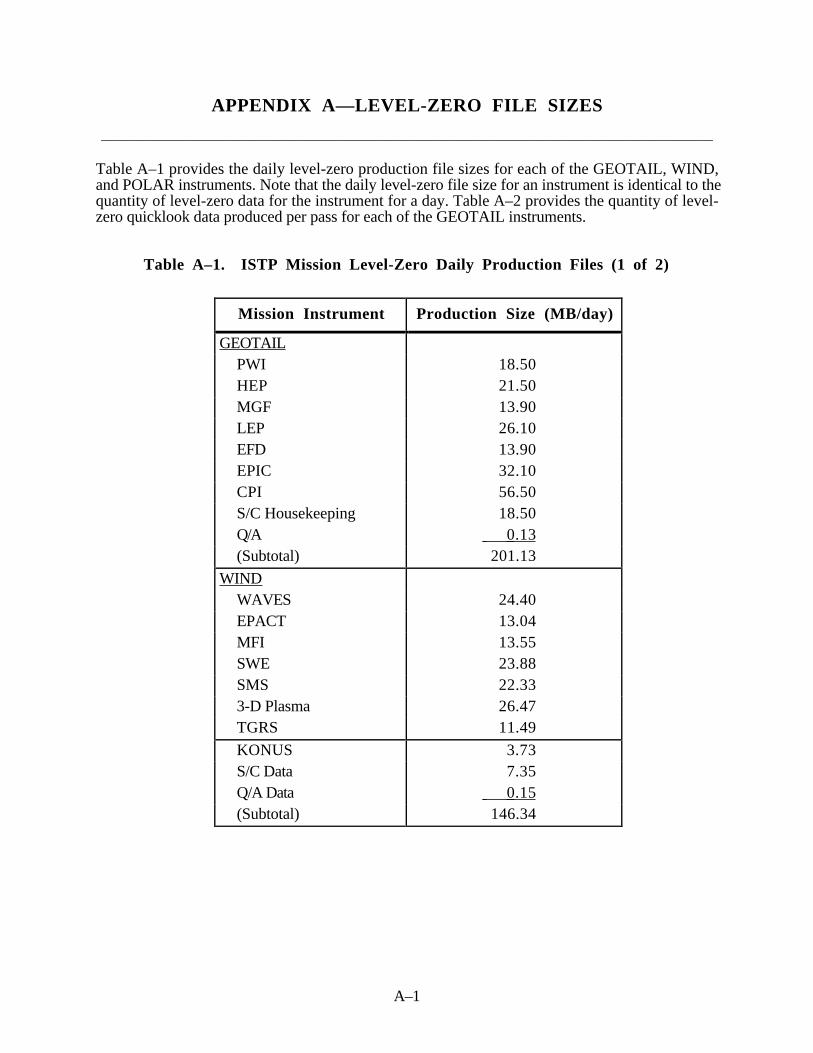
A–1
APPENDIX A—LEVEL-ZERO FILE SIZES
____________________________________________________________________________________________
Table A–1 provides the daily level-zero production file sizes for each of the GEOTAIL, WIND,and POLAR instruments. Note that the daily level-zero file size for an instrument is identical to thequantity of level-zero data for the instrument for a day. Table A–2 provides the quantity of level-zero quicklook data produced per pass for each of the GEOTAIL instruments.
Table A–1. ISTP Mission Level-Zero Daily Production Files (1 of 2)
Mission Instrument Production Size (MB/day)
GEOTAILPWI 18.50HEP 21.50MGF 13.90LEP 26.10EFD 13.90EPIC 32.10CPI 56.50S/C Housekeeping 18.50Q/A 0.13(Subtotal) 201.13
WINDWAVES 24.40EPACT 13.04MFI 13.55SWE 23.88SMS 22.333-D Plasma 26.47TGRS 11.49
KONUS 3.73S/C Data 7.35Q/A Data 0.15(Subtotal) 146.34

A–2
Table A–1. ISTP Mission Level-Zero Daily Production Files (2 of 2)
Mission Instrument Production Size (MB/day)
POLARPWI 57.38HYDRA 65.13MFE 18.64TIMAS 57.38TIDE 57.38UVI 152.95VIS 142.62PIXIE 65.13CAMMICE 28.98CEPPAD 47.05EFI 39.30SEPS (tbd)S/C Data 26.39Q/A Data 0.43(Subtotal) 758.76
Total 1106.30
Notes: 1. Production sizing is derived from telemetry formatand data rates.
2. Sizing estimates include 10-percent overhead.3. WIND and POLAR sizes are based on instrument
rates from the spacecraft contractor as provided inReference J.

A–3
Table A–2. GEOTAIL Level-Zero Quicklook Files
Mission Instrument Production Size (MB/pass)
PWI 0.78HEP 0.91MGF 0.60LEP 1.11EFD 0.91EPIC 1.37CPI 2.40S/C Data 0.78Q/A Data 0.02
Total 8.88

B–1
APPENDIX B—KEY PARAMETER VOLUMES
____________________________________________________________________________________________
Table B–1 presents the key parameter volumes for each of the ISTP GEOTAIL, WIND, POLAR,and ground-based experiments.
Table B–1. Key Parameter Volumes (1 of 2)
Mission Experiment Key Parameter Volume(MB/Day)
GEOTAIL PWI 0.078HEP 0.100MGF 0.034LEP 0.166EFD 0.056EPIC 0.342CPI 0.100
(subtotal) 0.876
WIND WAVES 0.133EPACT 0.111 *MFI 0.078SWE 0.111 *SMS 0.2763-D PLASMA 0.166TGRS 0.133KONUS 0.000
(subtotal) 1.008

B–2
Table B–1. Key Parameter Volumes (2 of 2)
Mission Experiment Key Parameter Volume(MB/Day)
POLAR PWI 0.111HYDRA 0.551 *MFE 1.101TIMAS 0.221TIDE 0.551UVI 26.511VIS 22.001PIXIE 2.696CAMMICE 0.551CEPPAD 0.815EFI 0.881SEPS 0.221 *
(subtotal) 56.211
Ground-Based CANOPUS 0.265DARN 0.749 **SESAME 0.098SONDRESTROMFJORD 0.221
(subtotal) 1.333
TOTAL 59.428
* Estimate, actual is TBS** 0.248 for first 2 yearsNote: All volumes include SFDU volume and 10-percent overhead.

C–1
APPENDIX C—EXTENDED MINOR FRAMES
____________________________________________________________________________________________
The GTDM DCF transfers extended minor frames of WIND and POLAR telemetry to the CDHFfor near–real–time processing.
The basic unit that provides data for ISTP processing is known as the minor frame. Satellitesproduce minor frames by incorporating data from instruments aboard satellites with header andtrailer data that uniquely identifies each minor frame. Some examples of header and trailer data arecounters, times associated with a minor frame, and the status of the satellite when it generated theminor frame. Each satellite produces a minor frame using formats specifically designed for thatsatellite. However every minor frame processed by ISTP can be divided into four basic fields. Thefour basic fields of a minor frame are defined as:
Minor Frame HeaderScientific Instrument DataFrame Frame WordMinor Frame Trailer
The minor frame header contains fields that indicates the status of the frame when the satellitegenerated the minor frame. The scientific instrument data field contains data from severalinstrument sensors on board the satellite multiplexed into a conglomeration of data based on aprespecified format. The frame synchronization word contains a bit pattern through which softwarekeeps minor frames in synchronization. The minor frame trailer contains minor frame identificationfields as well as the time that the minor frame was frame at the ground station.
Figure C–1 presents the WIND extended minor frame; Figure C–2 presents the POLAR frameminor frame.

C-2
0 1 2 3 4 5 6 7Minor Frame Counter
Format ID
Time Code
Major Frame Counter C&DH Status ACADS
Time Code
8 9 10 11 12 13 14 15
Space Housekeeping DataInstrument
Housekeeping DataACADS (cont’d)
16
SCIENTIFIC
INSTRUMENT
DATA
252 253 254 255Frame Synchronization
Word
byte number
256 257 258 259 260 261 262 263Milliseconds of Day
(27 bits)Microseconds of
MillisecondsAnalog/Digital Flags
(12 bits)Day of Year
(9 bits)
264 265 266 267 268 269 270 271
Physical Frame CounterCorrected
Major Frame Ctr.
Corrected Major
Frame Ctr.Edit Flags
Notes: 1.Each byte represents 8 bits. 2.Byte 1–Format ID/Time Code/C&DH Status Format ID subcommutated every 5 minor frames, starting with minor frame 0.
Time Code subcommutated every 25 minor frames, starting with minor frames 4, 9, and 14.
Byte 2–Major Frame Counter/Time Code/C&DH Status Major frame counter subcommutates every 25 minor frames, starting with
minor frame 0. Time Code subcommutated every 25 minor frames starting with minor frames 4, 9, and 14.
Figure C–1. WIND Extended Minor Frame

C–3
0 1 2 3 4 5 6 7Minor Frame Counter
C&DH Status Space Housekeeping Data
8 9 10
16
SCIENTIFIC
INSTRUMENT
DATA
252 253 254 255Frame Synchronization
Word
byte number
256 257 258 259 260 261 262 263Milliseconds of Day
(27 bits)Microseconds of
MillisecondsAnalog/Digital Flags
(12 bits)Day of Year
(9 bits)
264 265 266 267 268 269 270 271
Physical Frame CounterCorrected
Major Frame Ctr.
Corrected Major
Frame Ctr.Edit Flags
Notes:Each byte represents 8 bits.
Instrument Housekeeping Data
Figure C–2. POLAR Extended Minor Frame

D–1
APPENDIX D—FILE-NAMING CONVENTIONS, CD-ROMVOLUME IDENTIFIER, VOLUME DESCRIPTION AND INDEX
FILES, AND DIRECTORY STRUCTURE
____________________________________________________________________________________________
D . 1 File-Naming Conventions
In general, the ISTP data and associated SFDU files distributed by the DDF on physical mediaconform to the ISTP CDHF file-naming conventions described in detail in Section 2.6. However,two different file-naming conventions are used for SOHO data and SFDU files.
SOHO data files that are processed or used by the CDHF conform to the ISTP CDHF file-namingconventions, which are described in Section 2.6 and are summarized below. These files includethe G005 AOCS HK1, G007 Attitude 1, G008 Attitude 2, G013 CELIAS HK, G014 CEPACHK, G029 CELIAS Science, G030 CEPAC Science, G039 VIRGO Science, CELIAS KP,COSTEP KP, ERNE KP, all summary data, the as-run-plans, ancillary data, predictive anddefinitive orbit data, definitive attitude, full-time resolution attitude, and command history.
All other SOHO data files conform to the MOSDD Pacor II file-naming conventions, which aredescribed in Section 10 of Reference 12 and are summarized below. The following is anexplanation of the two file-naming conventions and their effect on the long and short (eight-character name with three-character extension) filenames of the SOHO data files.
Figure D–1 shows the Pacor II long file-naming convention, and Figure D–2 shows the Pacor IIshort file-naming convention. Figure D–3 shows the ISTP CDHF long file-naming convention,and Figure D–2 shows the ISTP CDHF short file-naming convention.
Filename Mission Name_Group_Data Type_Starttime_Version.File Extension
where:Mission Name SOHOGroup ID Gnnn (defined in Table D–1)Data Type QL (quick look) or LZ (level zero)Starttime YYYY-MM-DDThh:mm:ssZ, (where:
YYYY = Year (e.g., 1995)MM = Month (01–12)DD = Day of month (01–31)T = The alphabetic character “T” to separate the day from the timehh = Hour of the day (01–24)mm = Minute of the hour (01–60)ss = Second of the minute (01–60)Z = The alphabetic character “Z” for UTC
Version Vxx for version of the file (xx = 01 unless the file was reprocessed)File Extension DAT1 or SFDU (data file or associated SFDU file)
Figure D–1. Pacor II Long File-Naming Convention

D–2
Filename YDDD$$VV.File Extension
where:Y Last digit of year (e.g., 5 for 1995)DDD Julian date (001–366)$$ File number of day (e.g., 01 for first file of the day)VV Version number of file (VV = 01 for the first version of the file)File Extension Dxx or SFD, when SFDU references multiple files, xx will identify a specific
file.
Figure D–2. Pacor II Short File-Naming Convention
Filename Mission__Datatype_Descriptor_Date_Version.File Extension
where:Mission Identifies the mission or investigation (e.g., SO for SOHO)Datatype Identifies the type of data (e.g., LZ for level zero)Descriptor Describes or further qualifies the data (e.g., PRE for predictive data)Date Identifies the starting date of the data in the file, in the form YYYYMMDD,
where:YYYY = 4-digit year (e.g., 1995)MM = 2-digit month (01–12)DD = 2-digit day of month (01–31)
Version Identifies the version of the data (01–99)File Extension DAT = data file, SFD = SFDU file, CDF = Common Data Format
Sxx = data file segment, where xx= 01–99
Note: Missions, data types, and desciptors are listed in Section 2.6.
Figure D–3. ISTP CDHF Long File-Naming Convention
Filename YYMMDDVV.XXX
where:YY Last two digits of the year (e.g., 95 for 1995)MM Month (01–12)DD Day of the month (01–31)VV Version number of the file (01–99) (key parameters could be recomputed
several times)XXX File extension (e.g., DAT, CDF, SFD, S01-S99)
Figure D–4. ISTP CDHF Short File-Naming Convention

D–3
Table D–1. SOHO Group IDs
GROUP ID PACKET NAME GROUP ID PACKET NAME
G001 SVM HK1 G022 SUMER HKG002 SVM HK2 G023 SWAN HKG003 SVM HK3 G024 UVC HKG004 SVM HK4 G025 VIRGO HKG005 AOCS HK1 G026 CDS Science LRG006 AOCS HK2 G027 CDS Science MRG007 Attitude 1 G028 CDS Science HRG008 Attitude 2 G029 CELIAS ScienceG009 S/W G030 CEPAC ScienceG010 OBT G031 EIT/LASCO Science LRG011 Experiment HK G032 EIT/LASCO Science HRG012 CDS HK G033 GOLF ScienceG013 CELIAS HK G034 MDI ScienceG014 CEPAC HK G035 SUMER Science LRG015 EIT/LASCO HK1 G036 SUMER Science HRG016 EIT/LASCO HK2 G037 SWAN ScienceG017 EIT/LASCO HK3 G038 UVCS ScienceG018 GOLF HK G039 VIRGO ScienceG020 Reserved EGSE G0410 MDI HK
Thus the short Pacor II filename “51570101.D01” is equivalent to the ISTP CDHF filename“95060601.DAT.” That is Version 1 of a data file created on day 157 (June 6) of 1995.
The long filenames within the SFDU headers differ as follows:
Pacor II: SOHO_G001_LZ_1995-06-07T06-56-21Z_V01.DAT1;CDHF: SO_LZ_G001_19950607_V01.DAT
For more clarification, Figure D–5 contains a current SOHO SFDU received by the DDF from thePacor II system on June 7, 1995.
The Figure D–5 SFDU header and associated data file were then transferred to the CDHF and thenback to the DDF on June 8, 1995, with the SFDU header shown in Figure D–6; this headerconforms to the ISTP CDHF file-naming convention. Note the differences in the referenceparameters.

D–4
CCSD1Z00000100000552NSSD1K00021300000383
PROJECT=“ISTP>International Solar-Terrestrial Physics”;
DISCIPLINE=“Solar Physics>Solar and Heliospheric Observatory”;
SOURCE_NAME=“SOHO>Solar And Heliospheric Observatory”;
DATA_TYPE=“LZ>LevelZero”;
DESCRIPTOR=“G001>APID3”;
START_DATE=1995-06-07T06:56:21Z;
STOP_DATE=1995-06-07T15:58:22Z;
DATA_VERSION=1;
GENERATION_DATE=1995-06-07T21:01:29Z;
FILE_ID=SOHO_G001_LZ_1995-06-07T06-56-21Z_V01;
CCSD1R00000300000129
REFERENCETYPE=CCSDS0;
LABEL=NSSD3IE0R0010000000;
REFERENCE=(“$1=51570101.D01, $2=SOHO_G001_LZ_1995-06-07T06-56-21Z_V01.DAT1”);
Figure D–5. Pacor II SFDU Header
CCSD1Z00000100001004NSSD1K00006000000440
PROJECT = “ISTP>INTERNATIONAL SOLAR-TERRESTRIAL PHYSICS”;
DISCIPLINE = “SOLAR PHYSICS>SOLAR AND HELIOSPHERIC OBSERVATORY”;
SOURCE_NAME = “SOHO>SOLAR AND HELIOSPHERIC OBSERVATORY”;
DATA_TYPE = “LZ>LEVELZERO”;
DESCRIPTOR = “G001>APID3”;
START_DATE = 1995-06-07T06:56:21.555Z;
STOP_DATE = 1995-06-07T15:58:22.137Z;
DATA_VERSION = 1;
GENERATION_DATE = 1995-06-07T21:01:29Z;
FILE_ID = SO_LZ_G001_19950607_V01;
ICSS_RELEASE = “Release 5.1C”;
CCSD1R00000300000524
REFERENCETYPE = ($CCSDS3);
LABEL = NSSD3IE0000000000001;
REFERENCE = (“$1=95060701.DAT,$2=SO_LZ_G001_19950607_V01.DAT1”);
Figure D–6. ISTP CDHF SFDU Header
Note: Most of the rest of the information in this appendix has been extracted from Reference 3.
D.2. CD-ROM Description
The CD-ROMs used to distribute ISTP data conform to ISO 9660, which defines the physical andlogical formats of the CD-ROM. This ensures that most CD-ROM drives on most platforms will beable to read the ISTP CD-ROMs. Also, ISTP CD-ROMs follow other emerging NASA standards,guidelines, and practices, especially the use of CCSDS’s SFDUs and a file-naming and directory

D–5
structure that will be compatible with most platforms. For example, all copies of a CD-ROM areuniquely identified by one volume identifier. No other CD-ROM is labeled with the same identifier.Even an update has a different volume identifier from the volume it succeeds. Figure D–7 is avolume identifier description that illustrates how the CD-ROMs will be logically and physicallynamed, and it includes sample volume identifiers.
Every CD-ROM also contains several files that help describe its data. The root directory containsthe volume description file (VOLDESC.SFD). It is an ASCII SFDU-encapsulated file that lists theCD-ROM contents. Major VOLDESC.SFD items are a list of the distribution destinations and a listof files distributed to each destination. The filenames conform to the long file-naming conventionsspecified in Section D.1. A VOLDESC.SFD list of files can be parsed to allow for automatedselection of the desired file via the directory tree. The VOLDESC.SFD also contains the volumecreation date, product name, sequence number, and some SFDU information. Sections 2.4, 2.5,and D.1 describe the SFDUs. Figure D–8 is a sample VOLDESC.SFD file that illustrates thecontent of the file put on each CD-ROM to list its files.
Purpose: Name a CD-ROM carries.Format: USA_NASA_DDF_product_name_nnnn
where product_name is the name given to the product consisting of particular dataand nnnn is a 4-digit sequence number starting with 1 for the number of theCD-ROM set being distributed for that product.
Size: Up to 32 charactersExamples: USA_NASA_DDF_WI_LZ_0001
USA_NASA_DDF_GE_LEP_LZ_0001USA_NASA_DDF_PO_LZ_0001
Notes: 1. The sequence number identifies a specific distribution of a particular product.2. Every volume of a multivolume CD-ROM set has the same volume ID. The volume
number in the VOLDESC file of each CD-ROM volume identifies the specific volumeof a multivolume set.
Figure D–7. CD-ROM Volume ID Description
The root directory also contains subdirectories for documentation, indexes, and data. TheDOCUMENT subdirectory contains an abstract that provides a high-level description of the dataproduct. The INDEX subdirectory contains a file that allows the user to determine which CD-ROMcontains other files produced for the data product. This file provides a cumulative index of all filesdistributed to date on CD-ROM. The filenames conform to the long file-naming conventionsspecified in Section D.1. Figure D–9 is a sample of the Cumulative Index file put on eachCD-ROM to allow the user to determine which CD-ROM set contains other files produced for thedata product. The DATA subdirectory contains additional subdirectories that allow the data to begrouped logically, depending on the product.
The decision to distribute ISTP datasets using CD-ROMs has made it necessary to make sometechnical trade-offs regarding format and naming conventions and has resulted in a proposedextension to the SFDU standards. ISTP CD-ROMs will use the ISO 9660 Level 1 standard toprovide compatibility across major computing platforms. However, this standard has thedisadvantage of supporting only eight-character by three-character (8.3) filenames. As described in

D–6
CCSD3ZF0000100000001NSSD3KS00109VTOCMARK
DATE: 11-JAN-1993
PRODUCT NAME: ISTP DEMO
MEDIA CODE: CD
SEQUENCE NUMBER: 1
VOLUME NUMBER: 1
TYPE OF DISTRIBUTION:
DISTRIBUTION DESTINATIONS
WILLIAM MISH WM00 1
FILES DISTRIBUTED TO EACH DESTINATION
ABSTRACT.TXT DOCUMENT/ABSTRACT.TXT 2048
INDEX.TXT INDEX/INDEX.TXT 4096
CN_K0_BARS_19930106_V01.CDF DATA/CN/BARS/K0/93010601.CDF 64512 19930106000000 19930106235959
CN_K0_BARS_19930106_V01.SFDU DATA/CN/BARS/K0/93010601.SFD 1024 19930106000000 19930106235959
DN_K0_GBAY_19930104_V01.CDF DATA/DN/GBAY/K0/93010401.CDF 449024 19930104000000 19930104235959
DN_K0_GBAY_19930104_V01.SFDU DATA/DN/GBAY/K0/93010401.SFD 1024 19930104000000 19930104235959
DN_K0_PACE_19921229_V01.CDF DATA/DN/PACE/K0/92122901.CDF 480768 19921229000000 19921229235959
DN_K0_PACE_19921229_V01.SFDU DATA/DN/PACE/K0/92122901.SFD 1024 19921229000000 19921229235959
GE_AT_DEF_19921228_V01.CDF DATA/GE/DEF/AT/92122801.CDF 24064 19921228000000 19921228235959
GE_AT_DEF_19921228_V01.SFDU DATA/GE/DEF/AT/92122801.SFD 1024 19921228000000 19921228235959
GE_K0_EPI_19921226_V01.CDF DATA/GE/EPI/K0/92122601.CDF 349696 19921226000000 19921226235959
GE_K0_EPI_19921226_V01.SFDU DATA/GE/EPI/K0/92122601.SFD 1024 19921226000000 19921226235959
GE_K0_EPI_19930102_V01.DAT DATA/GE/EPI/LZ/93010201.DAT 289336332 19930102000000 19930102235959
GE_LZ_EPI_19930102_V01.SFDU DATA/GE/EPI/LZ/93010201.SFD 1024 19930102000000 19930102235959
GE_LZ_MGF_19930105_V01.DAT DATA/GE/MGF/LZ/93010501.DAT 12567040 19930105000000 19930105235959
GE_LZ_MGF_19930105_V01.SFDU DATA/GE/MGF/LZ/93010501.SFD 1024 19930105000000 19930105235959
CCSD$$MARKERVTOCMARKCCSD3RF0000300000001
REFERENCETYPE=$CCSDS3
LABEL = CCSD3SD0000200000001
REFERENCE = "$2=ABSTRACT.TXT,$1=DOCUMENT/ABSTRACT.TXT"
LABEL = NSSD3KF0013600000001
REFERENCE = "$2=INDEX.TXT,$1=INDEX/INDEX.TXT"
LABEL=ATTACHED
REFERENCE="$2=CN_K0_BARS_19930106_V01.SFDU,$1=DATA/CN/BARS/K0/93010601.SFD"
REFERENCE="$2=DN_K0_GBAY_19930104_V01.SFDU,$1=DATA/DN/GBAY/K0/93010401.SFD"
REFERENCE="$2=DN_K0_PACE_19921229_V01.SFDU,$1=DATA/DN/PACE/K0/92122901.SFD"
REFERENCE="$2=GE_AT_DEF_19921228_V01.SFDU,$1=DATA/GE/DEF/AT/92122801.SFD"
REFERENCE="$2=GE_K0_EPI_19921226_V01.SFDU,$1=DATA/GE/EPI/K0/92122601.SFD"
REFERENCE="$2=GE_LZ_EPI_19930102_V01.SFDU,$1=DATA/GE/EPI/LZ/93010201.SFD"
REFERENCE="$2=GE_LZ_MGF_19930105_V01.SFDU,$1=DATA/GE/MGF/LZ/93010501.SFD"
Figure D–8. Sample VOLDESC File

D–7
CN_K0_BARS_19920720_V01.SFDU USA_NASA_DDF_ISTP_DEMO_0001
DATA/CN/BARS/K0/92072001.SFD
DN_K0_GBAY_19930103_V01.SFDU USA_NASA_DDF_ISTP_DEMO_0001
DATA/DN/GBAY/K0/93010301.SFD
DN_K0_PACE_19921205_V01.SFDU USA_NASA_DDF_ISTP_DEMO_001
DATA/DN/PACE/K0/92120501.SFD
GE_AT_DEF_19920908_V01.SFDU USA_NASA_DDF_ISTP_DEMO_0001
DATA/GE/DEF/AT/92090801.SFD
GE_K0_EPI_19920908_V01.SFDU USA_NASA_DDF_ISTP_DEMO_0001
DATA/GE/EPI/K0/92090801.SFD
GE_LZ_EPI_19921231_V01.SFDU USA_NASA_DDF_ISTP_DEMO_0001
DATA/GE/EPI/LZ/92123101.SFD
GE_OR_DEF_19920727_V01.SFDU USA_NASA_DDF_ISTP_DEMO_0001
DATA/GE/DEF/OR/92072701.SFD
GE_OR_PRE_19920804_V01.SFDU USA_NASA_DDF_ISTP_DEMO_0001
DATA/GE/PRE/OR/92080401.SFD
GE_LZ_MGF_19930101_V01.SFDU USA_NASA_DDF_ISTP_DEMO_0001
DATA/GE/MGF/LZ/93010101.SFD
GE_SD_NUL_19930105_V01.SFDU USA_NASA_DDF_ISTP_DEMO_0001
DATA/GE/SD/93010501.SFD
I8_K0_MAG_19920825_V01.SFDU USA_NASA_DDF_ISTP_DEMO_0001
DATA/I8/MAG/K0/92082501.SFD
SE_K0_VLF_19921201_V01.SFDU USA_NASA_DDF_ISTP_DEMO_0001
DATA/SE/VLF/K0/92120101.SFD
GE_CH_NUL_19921201_V01.SFDU USA_NASA_DDF_ISTP_DEMO_001
DATA/GE/CH/93010101.SFD
Figure D–9. Sample Cumulative Index File
Section 2.6, the ISTP CDHF uses long filenames for conveying maximum informationrepresentation in the name. To provide CD-ROMs that continue to carry along the long filenames,the SFDUs have been modified such that both the long filenames and the corresponding short(8.3) filenames are present in the REFERENCE OBJECT portion of the SFDU. The shortfilenames are a subset of the long filenames (as described in Section D.1). The formats of the ISTPCDHF and Pacor II short and long filenames are given in Section D.1.
The CD-ROM has a directory structure that parallels the long filenames. The directory structureitself is used to convey the long filename information that is missing from the short filename. As aresult, a short filename, in combination with its position in the containing directory structure,conveys the same information as a long filename. Figure D–10 presents a schematic of a CD-ROMdirectory showing how the ISTP CDHF long filenames are used to develop a CD-ROM directory

D–8
.
Fig
ure
D–1
0. I
STP
CD
–RO
M D
irec
tory
Str
uctu
re (1
of
4)
VO
LDE
SC
.SF
D[IN
DE
X]
[DO
CU
ME
NT
][D
AT
A]
[RO
OT
]
[GE
][W
I][P
O]
[SO
][D
N]
[SE
][S
N]
[CN
][I8
][L
9]
[L0
][L
1]
[G6]
[G7]
[CL]
[PLA
][M
AG
]
[K0]
[K0]
[SO
PA
][M
PA
]
[K0]
[K0]
[MA
G]
[EP
S]
[K0]
[K0]
[CH
][C
PI]
[HP
L][H
PB
][E
PI]
[MG
F]
[EF
D]
[LE
P]
[PW
I][P
RE
][S
PH
A]
[QA
F]
[SC
R]
[SD
]
[OR
][A
T]
[OR
][A
T]
[DE
F]
[LZ
]
9208
020
1.S
FD
9208
0201
.DA
T
[K0]
[K1]
……
…[K
9]
920
8020
1.S
FD
9208
0201
.CD
F
= s
ubd
irect
ory
= i
nstr
umen
t di
rect
ory
pat
h =
0 th
roug
h 9
[XX
][S
L][S
X]
[IN]
[ ]
A, B
, Cn
AB
C[K
PQ
A]
[AN
]
[AU
XZ
]
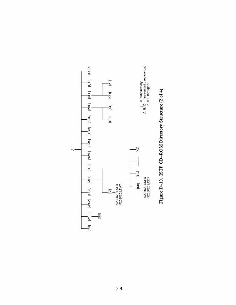
D–9
Fig
ure
D–1
0. I
STP
CD
–RO
M D
irec
tory
Str
uctu
re (
2 of
4)
A
[CH
][W
IFP
][W
AV
][E
PA
][M
FI]
[3D
P]
[SW
E]
[SM
S]
[TG
R]
[KO
N]
[DE
F]
[QA
F]
[SC
R]
[OR
][A
T]
[OR
][A
T]
[PR
E]
[LZ
]
9208
0201
.SF
D92
0802
01.D
AT
[K0]
[K1]
……
…[K
9]
9208
0201
.SF
D92
0802
01.C
DF
= s
ubdi
rect
ory
= i
nstr
umen
t dire
ctor
y pa
th =
0 th
roug
h 9
[ ]
A, B
, Cn
[SU
]

D–10
Fig
ure
D–1
0. I
STP
CD
–RO
M D
irec
tory
Str
uctu
re (
3 of
4)
B
[CH
][V
LT]
[PD
C]
[CA
M]
[EF
I][H
YD
][M
FE
][P
IX]
[PW
I][T
IM]
[UV
I][T
ID]
[LZ
]
9208
0201
.SF
D92
0802
01.D
AT
[K0]
[K1]
……
…[K
9]
9208
0201
.SF
D92
0802
01.C
DF
= s
ubdi
rect
ory
= i
nstr
umen
t dire
ctor
y pa
th =
0 th
roug
h 9
[ ]
A, B
, Cn
[AN
]
[VIS
][S
PH
A]
[PR
E]
[SC
R]
[SE
PS
]
[OR
][A
T]
[OR
][A
T]
[QA
F]
[DE
F]
[AN
]
[CE
P]
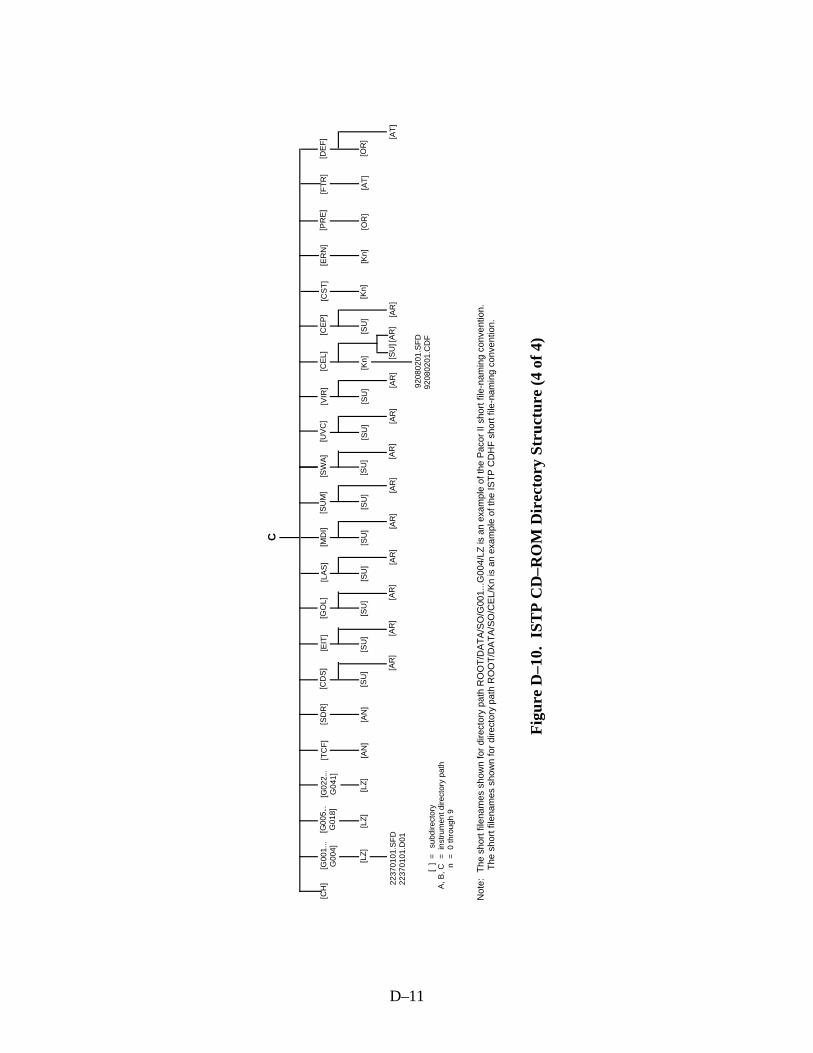
D–11
C
[CH
]
Fig
ure
D–1
0. I
STP
CD
–RO
M D
irec
tory
Str
uctu
re (
4 of
4)
[G00
1...
G00
4][G
005.
..G
018]
[G02
2...
G04
1][S
DR
][C
DS
][E
IT]
[GO
L][M
DI]
[SU
M]
[SC
R]
[LA
S]
=
subd
irect
ory
= i
nstr
umen
t dire
ctor
y pa
th =
0 th
roug
h 9
[ ]
A, B
, Cn
[LZ
]
[SW
A]
[UV
C]
[VIR
][E
RN
][P
RE
][C
ST
][C
EL]
[LZ
]
[FT
R]
[DE
F]
[LZ
][A
N]
[AN
][S
U]
[SU
][S
U]
[SU
][S
U]
[SU
][S
U]
[SU
][S
U]
[Kn]
[Kn]
[Kn]
[OR
][A
T]
[OR
]
[TC
F]
[AR
]
[CE
P]
[SU
]
[AR
][A
R]
[AR
][A
R]
[AR
][A
R]
[AR
][A
R]
[SU
][A
R]
[AT
][A
R]
2237
0101
.SF
D22
3701
01.D
01
9208
0201
.SF
D92
0802
01.C
DF
Not
e:
The
sho
rt fi
lena
mes
sho
wn
for
dire
ctor
y pa
th R
OO
T/D
AT
A/S
O/G
001.
..G00
4/LZ
is a
n ex
ampl
e of
the
Pac
or II
sho
rt fi
le-n
amin
g co
nven
tion.
T
he s
hort
file
nam
es s
how
n fo
r di
rect
ory
path
RO
OT
/DA
TA
/SO
/CE
L/K
n is
an
exam
ple
of th
e IS
TP
CD
HF
sho
rt fi
le-n
amin
g co
nven
tion.

D–12
structure and short filenames that are compatible with the ISO 9660 Level 1 standard. (Note thatthe directory structure names conform to the ISTP CDHF long file-naming convention althoughfilenames conform to either the ISTP CDHF or Pacor II short file-naming convention, asapplicable)
The directory structure has been updated to include directories for the following data files:
• Nonmission-specific key parameter quality ancillary data files• Fields and particles ancillary data files for the WIND mission• Color lookup table and pointing vector table ancillary data files for the VIS
experiment of the POLAR mission• Data files that support the SOHO mission• Data files for the Ulysses, SAMPEX, and the Interball missions
The nonmission-specific key parameter quality ancillary data files will reside in the directorydefined by the filename XX_AN_KPQA_yyyymmdd_Vnn under the DATA directory (e.g.,ROOT.DATA.XX.KPQA.AN).
The WIND fields and particles ancillary data files will reside in the directory defined by thefilename WI_SU_WIFP_yyyymmdd_Vnn under the DATA directory (e.g.,ROOT.DATA.WI.WIFP.SU).
The POLAR VIS experiment video color lookup table ancillary data files will reside in the directorydefined by the filename PO_AN_VLT_yyyymmdd_Vnn under the DATA directory (e.g.,ROOT.DATA.PO.VLT.AN).
The POLAR VIS experiment pointing vector table ancillary data files will reside in the directorydefined by the filename PO_AN_PDC_yyyymmdd_Vnn under the DATA directory (e.g.,ROOT.DATA.PO.PDC.AN).
The data files that support the SOHO mission include the following:
• SOHO level-zero and housekeeping data files• Key parameter data files for the CELIAS and the CEPAC (ERNE/COSTEP)
experiments• SOHO summary data and daily report files• SOHO ancillary data files for time correlation• SOHO command history files• SOHO definitive and predictive orbit data fields• SOHO definitive and full-time resolution attitude data files
The level-zero and housekeeping data files will reside in the directories defined by the filenameSO_LZ_Gnnn_yyyymmdd_Vnn under the DATA directory (e.g., ROOT.DATA.SO.G027.LZ).(Note that the files in these directories will be named using either the Pacor II or the ISTP CDHFshort filename, as applicable.)
The key parameter data files for the CELIAS experiment will reside in the directory definedby the filename SO_Kn_CEL_yyyymmdd_Vnn under the DATA directory (e.g.,ROOT.DATA.SO.CEL.Kn).

D–13
The key parameter data files for the CEPAC COSTEP experiment will reside in the directorydefined by the filename SO_Kn_CST_yyyymmdd_Vnn under the DATA directory (e.g.,ROOT.DATA.SO.CST.Kn)
The key parameter data files for the CEPAC ERNE experiment will reside in the directory definedby the filename SO_Kn_ERN_yyyymmdd_Vnn under the DATA directory (e.g.,ROOT.DATA.SO.ERN.Kn).
The SOHO summary data files will reside in the directory defined by the filenameSO_SU_<instrument/descriptor>_yyyymmdd_Vnn under the DATA directory (e.g.,ROOT.DATA.SO.CDS.SU).
The SOHO daily report data files will reside in the directory defined by the filenameSO_AR_<instrument/descriptor>_yyyymmdd_Vnn under the DATA directory (e.g.,ROOT.DATA.SO.LAS.AR).
The SOHO TCF ancillary data files will reside in the directory defined by the filenameSO_AN_TCF_yyyymmdd_Vnn under the DATA directory (e.g., ROOT.DATA.SO.TCF.AN).
The SOHO SDR ancillary data files will reside in the directory defined by the filenameSO_AN_SDR_yyyymmdd_Vnn under the DATA directory (e.g., ROOT.DATA.SO.SDR.AN).
The SOHO command history data files will reside in the directory defined by the filenameSO_CH_yyyymmdd_Vnn under the DATA directory (e.g., ROOT.DATA.SO.CH).
The SOHO predictive orbit data files will reside in the directory defined by the filenameSO_OR_PRE_yyyymmdd_Vnn under the DATA directory (e.g., ROOT.DATA.SO.PRE.OR).
The SOHO definitive orbit data files will reside in the directory defined by the filenameSO_OR_DEF_yyyymmdd_Vnn under the DATA directory (e.g., ROOT.DATA.SO.DEF.OR).
The SOHO definitive attitude data files will reside in the directory defined by the filenameSO_AT_DEF_yyyymmdd_Vnn under the DATA directory (e.g., ROOT.DATA.SO.DEF.AT).
The SOHO high-resolution attitude data files will reside in the directory defined by the filenameSO_AT_FTR_yyyymmdd_Vnn under the DATA directory (e.g., ROOT.DATA.SO.FTR.AT).
The data files for the Ulysses (UL), SAMPEX (SX), and Interball (IN) missions will reside in thedirectory defined by filenames of the form <mission short name>_Kn_<instrument/descriptor>_yyyymmdd_Vnn (e.g., ROOT.DATA.IN.TAIL.Kn).
It should be noted that this directory structure is based on the information that is currentlyavailable. The directory structure as it is currently designed can be easily expanded to adddirectories as required. There are three basic directories under the [ROOT.DATA] directory. Themission directories are the first-level directories under the [ROOT.DATA]. Under the missiondirectories are the instrument or descriptor directories. The lowest level directories are the data typedirectories. To set up directories for new data it is necessary to determine the mission, thedescriptor, and the data type. This information is provided in the data filename in the form< short mission name>_ <short data type name_<instrument/descriptor>_yyyymmdd_Vnn.
Note that even though the instrument/descriptor directory is under the short data type namedirectories, the descriptor comes after the data type in the data filename.
The two exceptions to adding new directories as described above are (1) the command historyfiles, and (2) the GEOTAIL SIRIUS data files, which always reside under the mission directory atthe same level as the instrument/descriptor directory.

E–1
APPENDIX E—POLAR WIDEBAND DATA
____________________________________________________________________________________________
This appendix provides the formats of the POLAR PWI wideband data.
E.1 Level-Zero Experiment File
The POLAR PWI wideband level-zero data are transferred in experiment files, each of whichcontains 1 hour of data segmented on the hour time boundary (01:00, 02:00, 03:00, etc.). Whentime-ordering is performed using the ground data capture time, segmentation will be at theprecision of one minor frame because each minor frame has an associated ground data capturetime. When time-ordering is performed using the PB5 clock in the data, segmentation will be at theprecision of one group of minor frames containing the PB5 clock. (For WBR, segmentation willbe at the precision of four minor frames. For HRP, segmentation will be at the precision of eightminor frames.) Each Experiment file, shown in Figure E–1, consists of a label record, containingdata quality and coverage information, followed by data records containing the actual spacecrafttelemetry. Detailed formats describing the Experiment file can be found in Figures E–1 throughE–7.
E.1 .1 Experiment File Label Record
Figure E–2 presents the Experiment file label record. The following entries describe each of thefields in the Experiment file label record:
a. Byte Location: 00000–00003Type/Length: Integer/4Description: The IPD Generic Data Capture Facility (GDCF) Satellite
Identification value used to identify POLAR data (always = 26)
b. Byte Location: 00004–00007Type/Length: Character/4Description: The PWI Wideband Instrument Name (always = “PWIW”)
c. Byte Location: 00008–00011Type/Length: Integer/4Description: The physical record number of the current record in the Experiment
file (for the label record, this value will always = 1)
d. Byte Location: 00012–00015Type/Length: Integer/4Description: The total number of physical records in the Experiment file
(including the label record)

E–2
Figure E–1. Experiment (EXP) File
Records
0001 - 0001 Label Records
0002 - n Data Records

E–3
Figure E–2. Experiment File Label Record (1 of 2)
Bytes
00000 - 00003 Spacecraft ID (=26)
00004 - 00007 Instrument Name (='PWIW')
00008 - 00011 Physical Record Number in File
00012 - 00015 Number of Physical Records in File
00016 - 00019 Raw Data Time – First Frame in File
00020 - 00023 Raw Data Time – First Frame in File (continued)
00024 - 00027 Raw Data Time – Last Frame in File
00028 - 00031 Raw Data Time – Last Frame in File (continued)
00032 - 00035 Corrected Data Time: Year – First Frame in File
00036 - 00039 Corrected Data Time: Day – First Frame in File
00040 - 00043 Corrected Data Time: Msec – First Frame in File
00044 - 00047 Corrected Data Time: Year – Last Frame in File
00048 - 00051 Corrected Data Time: Day – Last Frame in File
00052 - 00055 Corrected Data Time: Msec – Last Frame in File
00056 - 00059 Frame Counter – First Frame in File
00060 - 00063 Frame Counter – Last Frame in File
00064 - 00067 HRP Sequence Counter – First HRP Frame in File
00068 - 00071 HRP Sequence Counter – Last HRP Frame in File
00072 - 00075 Number of Frames Expected
00076 - 00079 Number of Frames in File

E–4
Figure E–2. Experiment File Label Record (2 of 2)
Bytes
00080 - 00083 Number of WBR Frames in File
00084 - 00087 Number of HRP Frames in File
00088 - 00091 Number of Perfect Frames in File
00092 - 00095 Spare
00096 - 00099 Spare
00100 - 00103 Number of Fill Frames in File
00104 - 00107 Number of Frames in File Flagged as Containing a Legitimate Mode Change
00108 - 00111 Number of Frames in File Flagged as Containing Mode Bits in Error
00112 - 00115 Number of Frames in File Flagged as Containing a Frame Counter Error
00116 - 00119 Number of Frames in File Flagged as Containing an HRP SequenceCounter Error
00120 - 00123 Number of Frames in File Flagged as Containing a Frame Synch Word Error
00124 - 00131 IPASS Program Version Number (8 Characters)
00132 - 00147 IPASS Program Run Date/Time (format = 'YYYY/DDDHHMNSS')(16 Characters)
00148 - 00151 IPASS Program Rerun Number
00152 - 00195 Experiment File Name as Catalogued on the LZPS (44 Characters)
00196 - 00239 SFDU File Name as Catalogued on the LZPS (44 Characters)
00240 - 00243 PB5/Ground Data Capture Time Processing Flag
00244 - 00247 IPASS Run Type
00248 - 00251 File-Level Sequence Number
00252 - 23231 Spare

E–5
Figure E–3. Experiment File Data Record
00000 - 00263
00264- 00527
00528 - 00791
00792 - 01055
01056 - 01319
22704 - 22967
22968 - 23231
Header
Frame #1
Frame #2
Frame #3
Frame #4
Frame #86
Frame #87
Note:Frame numbers correspond to physical frame number within a Data Record and do not bear any correlation to the 8-bit frame counter in the telemetry
•••
Bytes

E–6
Figure E–4. Experiment File Data Record Header
Notes: 1) Corrected Data Time is the time associated with the first frame in the record. 2) Raw Data Time is the uncorrected time associated with the first frame in the record. 3) When time-ordering is performed using ground data capture time, each minor frame has an associated data time. 4) When time-ordering is performed using the PB5 clock in the data, a group of frames is associated with a data time in the following manner: WBR Data – A data time is associated with up to four consecutive frames containing an 8-bit Frame Counter modulo 4 value that updates from 0 to 3 HRP Data – A data time is associated with up to eight consecutive frames containing an 11-bit HRP Sequence Counter modulo 8 value that updates from 0 to 7
Byte Number
Instrument Name ('PWIW')
0 1 2 3 4 5 6 7
Physical Record Number in File
Frame Counter - 1st Frame HRP Sequence Counter - 1st HRP Frame
Corrected Data Time -Year
Number of WBR Frames in Record
Raw Data Time
Number of Frames in Record
Number of Fill Frames in Record
Number of Frames in Record Containing Mode Bits in Error
Number of Frames in RecordContaining HRP Sequence Ctr Error
SPARE
Spare
Number of HRP Frames in Record
Number of Perfect Frames in Record
SPARE
Number of Frames in RecordIndicating Legitimate Mode Change
Number of Frames in Record Containing Frame Counter Error
Number of Frames in Record Containing Frame Sync Word (FSW) Error
Corrected Data Time -Day
8 9 10 11 12 13 14 15
16 17 18 19 20 21 22 23
24 25 26 27 28 29 30 31
32 33 34 35 36 37 38 39
40 41 42 43 44 45 46 47
48 49 50 51 52 53 54 55
56 57 58 59 60 61 62 63
64 65 66 67 68 69 70 71
72 73 74 75 76 77 78 79
256 257 258 259 260 261 262 263
Corrected Data Time -Milliseconds of Day

E–7
Figure E–5. Experiment File WBR Frame
Byte Number
0 1 2 3 4 5 6 7
FrameCounter
Mode
(5bits)
FIFO Data Clock
POLAR
Wideband
Instrument
Data
248 249 250 251 252 253 254 255
Frame SynchronizationWord
256 257 258 259 260 261 262 263
Ground Data Capture Time (11 bits Day of Year, 27 bitsMilliseconds of Day, 10 bits Microseconds of Millisecond)
StationID
QualityFlags
Notes:
1) Ground data capture time is extrapolated from the time tagged on the Nascom block
without correction (due to transmission errors, etc.).
2) Station ID is defined as follows:
1 = Canberra
2 = Goldstone
3 = Madrid

E–8
Figure E–6. Experiment File HRP Frame
Byte Number
0 1 2 3 4 5 6 7
FrameCounter
Mode
(5bits)
HRPSequenceCounter
DataClock
POLAR
Wideband
Instrument
Data
248 249 250 251 252 253 254 255
Frame Synchronization Word
256 257 258 259 260 261 262 263
Ground Data Capture Time (11 bits Day of Year, 27 bitsMilliseconds of Day, 10 bits Microseconds of Millisecond)
StationID
QualityFlags
Notes:
1) Ground data capture time is extrapolated from the time tagged on the Nascom block
without correction (due to transmission errors, etc.).
2) Station ID is defined as follows:
1 = Canberra
2 = Goldstone
3 = Madrid
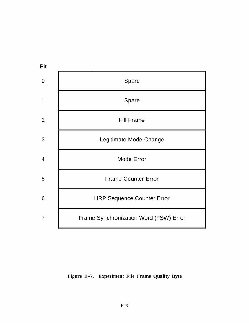
E–9
Figure E–7. Experiment File Frame Quality Byte
Bit
0 Spare
1 Spare
2 Fill Frame
3 Legitimate Mode Change
4 Mode Error
5 Frame Counter Error
6 HRP Sequence Counter Error
7 Frame Synchronization Word (FSW) Error

E–10
e. Byte Location: 00016–00023Type/Length: Byte/8Description: The uncorrected PB5 time code or ground data capture time
associated with the last frame in the Experiment file
f. Byte Location: 00024–00031Type/Length: Byte/8Description: The uncorrected PB5 time code or ground data capture time
associated with the last frame in the Experiment file
g. Byte Location: 00032–00035Type/Length: Integer/4Description: The corrected PB5/ground data capture time year associated with
the first frame in the Experiment file
h. Byte Location: 00036–00039Type/Length: Integer/4Description: The corrected PB5/ground data capture time day of year associated
with the first frame in the Experiment file
i. Byte Location: 00040–00043Type/Length: Integer/4Description: The corrected PB5/ground data capture time milliseconds of day
associated with the first frame in the Experiment file
j. Byte Location: 00044–00047Type/Length: Integer/4Description: The corrected PB5/ground data capture time year associated with
the last frame in the Experiment file
k. Byte Location: 00048–00051Type/Length: Integer/4Description: The corrected PB5/ground data capture time day of year associated
with the last frame in the Experiment file
l. Byte Location: 00052–00055Type/Length: Integer/4Description: The corrected PB5/ground data capture time milliseconds of day
associated with the last frame in the Experiment file

E–11
m. Byte Location: 00056–00059Type/Length: Integer/4Description: The corrected frame counter of the first frame in the Experiment file
n. Byte Location: 00060–00063Type/Length: Integer/4Description: The corrected frame counter of the last frame in the Experiment file
o. Byte Location: 00064–00067Type/Length: Integer/4Description: The corrected HRP sequence counter of the first HRP frame in the
Experiment file
p. Byte Location: 00068–00071Type/Length: Integer/4Description: The corrected HRP sequence counter of the last HRP frame in the
Experiment file
q. Byte Location: 00072–00075Type/Length: Integer/4Description: The number of frames expected to be in the Experiment file,
calculated using the corrected times of the first and last frame in thefile and the nominal time per frame
r. Byte Location: 00076–00079Type/Length: Integer/4Description: The total number of frames, including fill, in the Experiment file
s . Byte Location: 00080–00083Type/Length: Integer/4Description: The number of WBR frames, including fill, in the Experiment file
t. Byte Location: 00084–00087Type/Length: Integer/4Description: The number of HRP frames, including fill, in the Experiment file

E–12
u. Byte Location: 00088–00091Type/Length: Integer/4Description: The total number of non-fill frames in the Experiment file that did
not contain a mode error, a frame counter error, an HRP sequencecounter error, or a frame synch word error
v. Byte Location: 00092–00099Type/Length: Byte/8Description: Spare
w. Byte Location: 00100–00103Type/Length: Integer/4Description: The total number of fill frames in the Experiment file
x. Byte Location: 00104–00107Type/Length: Integer/4Description: The total number of frames in the Experiment file flagged as
signifying a legitimate mode change
y. Byte Location: 00108–00111Type/Length: Integer/4Description: The total number of frames in the Experiment file flagged as
containing mode bits in error
z. Byte Location: 00112–00115Type/Length: Integer/4Description: The total number of frames in the Experiment file flagged as
containing a frame counter error
aa. Byte Location: 00116–00119Type/Length: Integer/4Description: The total number of frames in the Experiment file flagged as
containing an HRP sequence counter error
bb. Byte Location: 00120–00123Type/Length: Integer/4Description: The total number of frames in the Experiment file flagged as
containing a frame synch word error

E–13
cc. Byte Location: 00124–00131Type/Length: Character/8Description: The version number of the IPASS software that was used to create
the Experiment file
dd. Byte Location: 00132–00147Type/Length: Character/16Description: The IPASS job run date and time in format “YYYY/DDD
HHMNSS”
ee. Byte Location: 00148–00151Type/Length: Integer/4Description: The IPASS job rerun number
ff. Byte Location: 00152–00195Type/Length: Character/44Description: The Experiment file name as catalogued on the LZPS
Format = “EXP.L26.RYYDDD.THHMNSS.IUU” (left justified)
Where:
L = Level Zero Processing System Database Level(Production, Test, or Development)
R = IPASS Run Type (Production or Quicklook)
YY = Experiment file generation time—year
DDD = Experiment file generation time—day of year
HH = Experiment file generation time—hour of day
MN = Experiment file generation time—minute of hour
SS = Experiment file generation time—second of minute
UU = Segment number (beginning with 1) of the datacontained in the Experiment file

E–14
gg. Byte Location: 00196–00239Type/Length: Character/44Description: The SFDU file name as catalogued on the LZPS
Format = “EXP.L26.RYYDDD.THHMNSS.SUU” (left justified)
Where:
L = Level Zero Processing System Database Level(Production, Test, or Development)
R = IPASS Run Type (Production or Quicklook)
YY = SFDU file generation time—year
DDD = SFDU file generation time—day of year
HH = SFDU file generation time—hour of day
MN = SFDU file generation time—minute of hour
SS = SFDU file generation time—second of minute
UU = Segment number (beginning with 1) of the datacontained in the Experiment file
hh. Byte Location: 00240–00243Type/Length: Integer/4Description: Flag indicating whether the data was time-ordered and segmented
using the PB5 time code present in the data or the ground datacapture time; all ancillary time-related fields present in theExperiment File Label Record and Data Record Headers reflect theindicated time-ordering method
ii. Byte Location: 00244–00247Type/Length: Character/4Description: The IPASS job run type
jj. Byte Location: 00248–00251Type/Length: Integer/4Description: The Experiment file version number (will be set to one for the first
Experiment file containing data for a given year, day, and hour andwill be incremented by one for each Experiment file createdthereafter containing data from the same year, day, and hour)
kk. Byte Location: 00252–23231Type/Length: Byte/22980Description: Spare
E.1 .2 Experiment File Data Record
Figure E–3 presents the Experiment file data record. The data record consists of a data recordheader and a number of frames.
E–15
E.1 .3 Experiment File Data Record Header
Figure E–4 presents the Experiment file data record header. The following entries describe each ofthe fields in the Experiment file data record header:
a. Byte Location: 000–003Type/Length: Character/4Description: The PWI Wideband Instrument Name (always = “PWIW”)
b. Byte Location: 004–007Type/Length: Integer/4Description: The physical record number within the Experiment file of the
current record
c. Byte Location: 008–011Type/Length: Integer/4Description: The corrected frame counter of the first frame in the record
d. Byte Location: 012–015Type/Length: Integer/4Description: The corrected HRP sequence counter of the first HRP frame in the
record
e. Byte Location: 016–017Type/Length: Integer/2Description: The corrected time year associated with the first frame in the record
f. Byte Location: 018–019Type/Length: Integer/2Description: The corrected time day of year associated with the first frame in the
record
g. Byte Location: 020–023Type/Length: Integer/4Description: The corrected time milliseconds of day associated with the first
frame in the record
h. Byte Location: 024–029Type/Length: Byte/6Description: The uncorrected time code associated with the first frame in the
record
i. Byte Location: 030–031Type/Length: Byte/2Description: Spare

E–16
j. Byte Location: 032–035Type/Length: Integer/4Description: The number of WBR frames, including fill, in the record
k. Byte Location: 036–039Type/Length: Integer/4Description: The number of HRP frames, including fill, in the record
l. Byte Location: 040–043Type/Length: Integer/4Description: The total number of frames, including fill, in the record
m. Byte Location: 044–047Type/Length: Integer/4Description: The number of non-fill frames in the record that are not flagged as
indicating a mode error, a frame counter error, an HRP sequencecounter error, or a frame synch word error
n. Byte Location: 048–055Type/Length: Byte/8Description: Spare
o. Byte Location: 056–059Type/Length: Integer/4Description: The number of fill frames in the record
p. Byte Location: 060–063Type/Length: Integer/4Description: The number of frames in the record flagged as indicating a
legitimate mode change
q. Byte Location: 064–067Type/Length: Integer/4Description: The number of frames in the record flagged as containing a mode
error
r. Byte Location: 068–071Type/Length: Integer/4Description: The number of frames in the record flagged as containing a frame
counter error
s . Byte Location: 072–075Type/Length: Integer/4Description: The number of frames in the record flagged as containing an HRP
sequence counter error

E–17
t. Byte Location: 076–079Type/Length: Integer/4Description: The number of frames in the record flagged as containing a frame
synch word error
u. Byte Location: 080–263Type/Length: Byte/184Description: Spare
E.1 .4 Experiment File Minor Frames
Figure E–5 presents the Experiment file WBR minor frame; Figure E–6 presents the Experimentfile HRP minor frame. The following entries describe each of the fields in an Experiment file minorframe:
a. Byte Location: 000–252Type/Length: Byte/253Description: Spacecraft telemetry as downlinked from the spacecraft
b. Byte Location: 253–255Type/Length: Byte/3Description: Frame Synchronization Word (=HEX ‘FAF320’)
c. Byte Location: 256–261Type/Length: Byte/6Description: The time that the minor frame was captured at the Deep Space
Network (DSN) site, formatted as follows:
Bits 00–10 = Day of year
Bits 11–37 = Milliseconds of day
Bits 38–47 = Microseconds of millisecond
This time is extrapolated from the time tagged on the Nascomblocks, without correction (due to transmission errors, etc.)
d. Byte Location: 262–262Type/Length: Byte/1Description: Station ID of the DSN site that captured the minor frame, specified
as follows:
Station ID # 1 = Canberra, Australia
Station ID # 2 = Goldstone, California
Station ID # 3 = Madrid, Spain

E–18
e. Byte Location: 263–263Type/Length: Byte/1Description: Flags describing the quality of the minor frame
E.1 .5 Experiment File Minor Frame Quality ByteFigure E–7 presents the Experiment file minor frame quality byte. The following entries describeeach of the flags in the Experiment file minor frame quality byte:
a. Bit Location: 0–1Type/Length: Binary digit/2Description: Spare
b. Bit Location: 2–2Type/Length: Binary digit/1Description: Flag indicating a fill frame
c. Bit Location: 3–3Type/Length: Binary digit/1Description: Flag indicating that a legitimate mode change (WBR to HRP or
HRP to WBR) has occurred
d. Bit Location: 4–4Type/Length: Binary digit/1Description: Flag indicating that the mode bits contain an error (A parameterized
number of continuous frames of the same mode must be found inorder for that mode to be recognized as valid)
e. Bit Location: 5–5Type/Length: Binary digit/1Description: Flag indicating that 1 or more bits of the frame counter were in
error
f. Bit Location: 6–6
Type/Length: Binary digit/1
Description: Flag indicating that 1 or more bits of the HRP sequence counterwere in error
g. Bit Location: 7–7Type/Length: Binary digit/1Description: Flag indicating that 1 or more bits of the frame synch word were in
error

E–19
E.2 Standard Formatted Data Unit File
Information describing a single Experiment file can be found in a detached header file known as thestandard formatted data unit (SFDU) file. One SFDU file is created for each Experiment file.Figure E–8 is an example of a typical SFDU file.

E–20
Record Bytes
1 000–039
042–096
099–148
151–190
193–235
238–268
271–302
305–335
338–374
377–392
395–427
430–449
452–475
478–504
507–509
2 000–059
062–509
CCSD1Z00000100001004NSSD1K0000600006000000390
PROJECT=“ISTP>International Solar-Terrestrial Physics”;
DISCIPLINE=“Space Physics>Interplanetary Studies”;
MISSION=“POLAR>Polar Plasma Laboratory”;
DESCRIPTOR=“PWI>Plasma Wave Investigation”;
DATA_TYPE=“WB>POLAR Wide Band”;
START_DATE=1993-04-10T00:00:00Z;
STOP_DATE=1993-04-10T00:59:59Z;
GENERATION_DATE=1993-12-02T20:43:57Z
DATA_VERSION=1;
FILE_I =PO_WB_PWI_1993041000_V01;
CCSD1R00000300000574
REFERENCETYPE=($CCSDS3);
LABEL=NSSD3IE0018600000001;
REFERENCE=(“$1=93041001.I00,$2=PO_WB_PWI_1993041000_V01.DAT”);
Notes: i) 1 SFDU File = 2 Records
ii) 1 Record = 512 Bytes iii) Each line is followed by:
Carriage Return (ASCII hex 0D) Line Feed (ASCII hex 0A)
Figure E–8. Example of an SFDU File
F–1
APPENDIX F—NEAR REAL TIME SERVER DATA
____________________________________________________________________________________________
The data messages from the CDHF NRT subsystem Server have the format shown in Figure F–1.An NRT Server data message is composed of three parts:
• Header (24 bytes)
• Body (variable length)
• Trailer (8 bytes)
The message header contains four items:
• Block start indicator (8 bytes)—ASCII string “STARTBLK”
• Experiment indicator (4 bytes) (see Table F–1 for possible indicator values)
• Byte count (4 bytes)—Total number of bytes in a data block—IEEE 4-byte binary integer
• Time of transmission (8 bytes)—64-bit binary time
The message body contains either control information or level-zero data for a WIND or POLARinvestigation. If the message is a control message in which the experiment indicator has a value of“CTL,” the message has three possible formats:
• Used to indicate beginning of data passMessage body: 11-character ASCII string “STARTOFPASS”
• Used to indicate end of data passMessage body: 9-character ASCII string “ENDOFPASS”
• Used to indicate resumption of data after a transmit gap within the passMessage body: 10-character ASCII string “RESUMEPASS”
Note: The NRT software handles the following interruptions:– Upstream disconnects– Failures in edit and decommutation recovery– KPGS floating-point traps
If the message contains level-zero data, the experiment indicator contains one of the values shownin Table F–1 and the message body contains the level-zero data for the corresponding WIND orPOLAR instrument, as described in Section 3.1 and its subsections. The message body beginswith an FLR, as described in Section 3.1.1. Each data record begins with a DRH, as described inSection 3.1.2, and contains the level-zero data for one major frame.
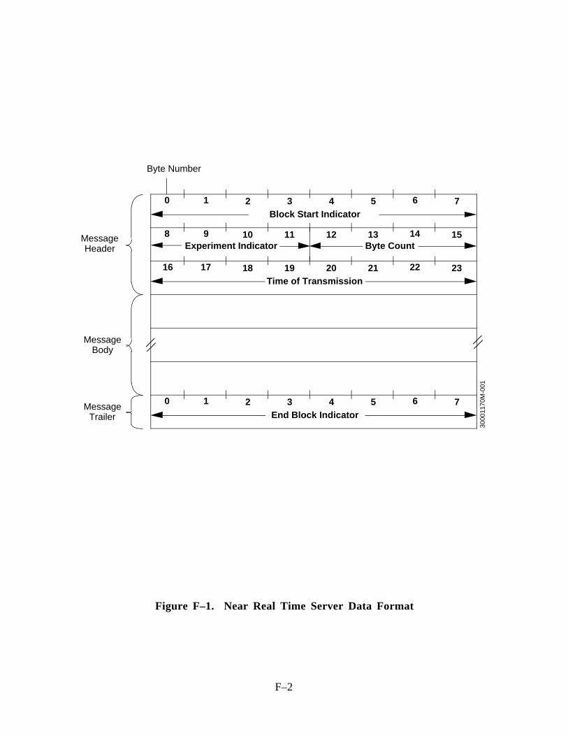
F–2
0 1 2 3 4 5 6 7Block Start Indicator
8 9 10 11 12 13 14 15
16 17 18 19 20 21 22 23
Experiment Indicator Byte Count
Time of Transmission
0 1 2 3 4 5 6 7End Block Indicator
MessageHeader
MessageBody
MessageTrailer
3000
1170
M-0
01
Byte Number
Figure F–1. Near Real Time Server Data Format
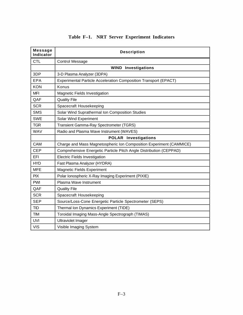
F–3
Table F–1. NRT Server Experiment Indicators
MessageIndicator
Description
CTL Control Message
WIND Investigations
3DP 3-D Plasma Analyzer (3DPA)
EPA Experimental Particle Acceleration Composition Transport (EPACT)
KON Konus
MFI Magnetic Fields Investigation
QAF Quality File
SCR Spacecraft Housekeeping
SMS Solar Wind Suprathermal Ion Composition Studies
SWE Solar Wind Experiment
TGR Transient Gamma-Ray Spectrometer (TGRS)
WAV Radio and Plasma Wave Instrument (WAVES)
POLAR Investigations
CAM Charge and Mass Magnetospheric Ion Composition Experiment (CAMMICE)
CEP Comprehensive Energetic Particle Pitch Angle Distribution (CEPPAD)
EFI Electric Fields Investigation
HYD Fast Plasma Analyzer (HYDRA)
MFE Magnetic Fields Experiment
PIX Polar Ionospheric X-Ray Imaging Experiment (PIXIE)
PWI Plasma Wave Instrument
QAF Quality File
SCR Spacecraft Housekeeping
SEP Source/Loss-Cone Energetic Particle Spectrometer (SEPS)
TID Thermal Ion Dynamics Experiment (TIDE)
TIM Toroidal Imaging Mass-Angle Spectrograph (TIMAS)
UVI Ultraviolet Imager
VIS Visible Imaging System

LA–1
LIST OF ACRONYMS
____________________________________________________________________________________________
3DPA 3-D Plasma AnalyzerADI authority and description identifierAIS Advanced Ionospheric SounderANSI American National Standards InstituteAPL Applied Physics LaboratoryARDB As-Run DatabaseASCII American Standard Code for Information InterchangeASI All Sky ImagerASPOC Active Spacecraft Potential ControlATC absolute time codeAUX auxiliaryBARS BARS VHF RadarBAS British Antarctic Surveybpi bits per inchCA control authorityCAID control authority identifierCAMMICE Charge and Mass Magnetospheric Ion Composition ExperimentCANOPUS Canadian Auroral Network for the Origin of Plasmas in Earth’s
Neighborhood Program Unified StudyCCB configuration control boardCCR change control reportCCSDS Consultative Committee for Space Data SystemsCCTV closed circuit televisionCD collision detectionCDF common data formatCDHF Central Data Handling FacilityCDR critical design reviewCD-ROM compact disc—read-only memoryCDS Coronal Diagnostic SpectrometerCELIAS Charge, Element, and Isotope Analysis SystemCEPAC COSTEP-ERNE Particle Analysis CollaborationCEPPAD Comprehensive Energetic Particle Pitch Angle DistributionCIO contents identifier objectCIS CLUSTER Ion Spectrometry ExperimentCMS Command Management SystemCnt countCo-I co-investigatorCOSTR Collaborative Solar-Terrestrial ResearchCPI Comprehensive Plasma InstrumentationCR carriage returnCRC cyclic redundancy check
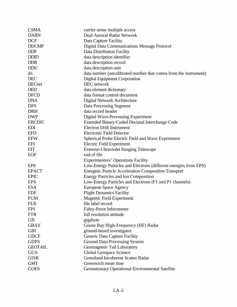
LA–2
CSMA carrier sense multiple accessDARN Dual Auroral Radar NetworkDCF Data Capture FacilityDDCMP Digital Data Communications Message ProtocolDDF Data Distribution FacilityDDID data description identifierDDR data description recordDDU data description unitdn data number (uncalibrated number that comes from the instrument)DEC Digital Equipment CorporationDECnet DEC networkDED data element dictionaryDFCD data format control documentDNA Digital Network ArchitectureDPS Data Processing SegmentDRH data record headerDWP Digital Wave-Processing ExperimentEBCDIC Extended Binary-Coded Decimal Interchange CodeEDI Electron Drift InstrumentEFD Electronic Field DetectorEFW Spherical Probe Electric Field and Wave ExperimentEFI Electric Field ExperimentEIT Extreme-Ultraviolet Imaging TelescopeEOF end of file
Experimentors’ Operations FacilityEP8 Low-Energy Particles and Electrons (different energies from EPS)EPACT Energetic Particle Acceleration Composition TransportEPIC Energy Particles and Ion CompositionEPS Low-Energy Particles and Electrons (F1 and P1 channels)ESA European Space AgencyFDF Flight Dynamics FacilityFGM Magnetic Field ExperimentFLR file label recordFPI Fabry-Perot InferometerFTR full resolution attitudeGB gigabyteGBAY Goose Bay High-Frequency (HF) RadarGBI ground-based investigatorGDCF Generic Data Capture FacilityGDPS Ground Data Processing SystemGEOTAIL Geomagnetic Tail LaboratoryGGS Global Geospace ScienceGISR Greenland Incoherent Scatter RadarGMT Greenwich mean timeGOES Geostationary Operational Environmental Satellite

LA–3
GOLF Global Oscillations at Low FrequenciesGSE Geocentric Solar EclipticGSFC Goddard Space Flight CenterGSM Geocentric Solar MagnetosphericGTDM generic time-division multiplexedHEP high-energy particlesHF high frequencyHYDRA Fast Plasma AnalyzerIBM International Business MachinesICD interface control documentID identifierIDU information data unitIEEE Institute of Electrical and Electronics EngineeringIMC Ionospheric-Magnetospheric CouplingIMSL International Mathematics and Statistics LibraryIMSS InfoLAN Mass Storage SystemInfoLAN IPD local area networkI/O input/outputIPD Information Processing DivisionIPLOT ISTP Plotting SystemISAS Institute of Space and Astronautical ScienceISO International Organization for StandardizationISTP International Solar-Terrestrial PhysicskB kilobytekbps kilobits per secondKPGS key parameter generation softwareLACN local area computing networkLAN local area networkLANL Los Alamos National LaboratoryLASCO Large-Angle Spectrometric CoronographLEP low-energy particlesLF line feedLVO label-value objectLZ level zeromag magnetometerMAG Fluxgate MagnetometerMARIA Magnetometer and Riometer ArrayMB megabyteMbps megabits per secondMCE Multicoordinate EphemerisMDI Michelson Doppler ImagerMFE Magnetic Field InvestigationMFI Magnetic Field InvestigationMGF magnetic fieldMOSDD Mission Operations and Systems Development Division

LA–4
MPA Meridian Photometer Arrayms millisecondµsec microsecondMSFC Marshall Space Flight CenterMVS multiple virtual storageNAG numerical algorithmsNASA National Aeronautics and Space AdministrationNOAA National Oceanic and Atmospheric AdministrationNRT near-real timeNSI NASA Science InternetNSN NASA Science NetworkNSP Network Services ProtocolNSSDC National Space Science Data CenterOSI Open Systems InterconnectionPACE Halley Station Polar Anglo-American Conjugate ExperimentPARL Lockheed Martin Palo Alto Research LaboratoryPacor II Packet Processor Data Capture Facility IIPEACE Plasma Electron and Current ExperimentPI principal investigatorPIXIE Polar Ionospheric X-ray Imaging ExperimentPLA Plasma InvestigationPOLAR Polar Plasma LaboratoryPWI Plasma Wave InstrumentQ/A quality and accountingRA Restricted ASCIIRAPID Imaging Energetic Particle SpectrometerRDAF remote data analysis facilityRID review item dispositionRIO riometerSABR Sabre VHF RadarSAKK Saskatoon-KapuskingSAMPEX Solar Anomalous and Magnetospheric Particle ExplorerSDPF Sensor Data Processing FacilitySDR SOHO Daily ReportSESAME Satellite Experiments Simultaneous with Antarctic MeasurementsSFDU standard formatted data unitSIRIUS Scientific Information Retrieval Integrated Utilization SystemSL Solar-Terrestrial Environment Laboratory, Nagoya UniversitySMS Solar Wind Suprathermal Ion Composition StudiesSOHO Solar and Heliospheric ObservatorySondrestrom Sondre Stromfjord RadarSPA Synchronous Orbit Particle AnalyzerSPAN Space Physics Analysis NetworkSPHA spin phase attitude dataSPOF Science Planning and Operations Facility

LA–5
SS substorm simulationSTAFF Spatio-Temporal Analysis of Field Fluctuations ExperimentSUMER Solar Ultraviolet Measurements of Emitted RadiationSWAN Solar Wind AnisotropiesSWE Solar Wind ExperimentSWIM Solar Wind Interplanetary MissionSWMC Solar Wind Magnetospheric CouplingTBD to be determinedTBS to be suppliedTCF time correlation fileTCP/IP Transmission Control Protocol/Internet ProtocolTED Total Energy DepositionTGRS Transient Gamma Ray SpectrometerTI theory investigatorTIDE Thermal Ion Dynamics ExperimentTIMAS Toroidal Imaging Mass-Angle SpectrographTLVO type-length-value-objectUCB University of California, BerkeleyUCLA University of California, Los AngelesUTC universal time coordinatedUVCS Ultraviolet Coronal SpectrometerUVI Ultraviolet ImagerVAX virtual address extensionVELOX VLF/ELF Logger ExperimentVHF very-high frequencyVIRGO Variability of Solar Irradiance Gravity OscillationsVIS Visible Imaging SystemVMS Virtual Memory SystemVOLDESC volume description fileWAVES Radio Plasma Wave InstrumentWHISPER Sounder and High-Frequency Wave Analyzer ExperimentWIND Interplanetary Physics Laboratory Mission
RF–1
REFERENCES
____________________________________________________________________________________________
CITED REFERENCES
1. National Aeronautics and Space Administration, Goddard Space Flight Center,IPD-8SRS/0389, System Requirements Specification for the International Solar-TerrestrialPhysics (ISTP) Program Data Processing Segment (DPS), Revision 3, August 1994
2. —, 560-1ICD/3490, Interface Control Document Between the International Solar-TerrestrialPhysics (ISTP) program Control Data Handling Facility (CDHF) and the Generic DataCapture Facility (GDCF) and the Data Distribution Facility (DDF), Revision 1, January 1996
3. —, ISTP Science Data Systems and Projects, William H. Mish, Mauricio Peredo, James L.Green, and Mary G. Reph, December 1993
4. Consultative Committee for Space Data Systems, Recommendation for Space Data SystemStandards, Standard Formatted Data Units—Structure and Construction Rules, CCSDS620.0.B–2, Blue Book, Issue 2, May 1992
5. National Aeronautics and Space Administration, Goddard Space Flight Center,NSSDC/WDC-A-R&S 19–31, NSSDC CDF User's Guide for VMS Systems, Version 2.1,December 1991
6. —, 560-7SUG/0290, ISTP CDHF Software System (ICSS) Programmer’s Guide to KeyParameter Generation Software, Revision 5, September 1995
7. —, 501-212/GEOTAIL, International Solar-Terrestrial Physics (ISTP) ProjectCollaborativeSolar-Terrestrial Research (COSTR) Initiative Systems & OperationsRequirements Document for GEOTAIL, Signature, January 1992
8. General Electric Company, Astro Space Division, Command and Telemetry Handbook,WIND, Revision 3.2, September 1, 1993
9. Martin-Marietta Astro Space, POLAR Command and Telemetry Handbook, Revision 3.0,May 1, 1993
10. Support Instrumentation Requirements Document (SIRD) for the WIND/POLAR Spacecraft,Signature, February 1992
11. National Aeronautics and Space Administration, Goddard Space Flight Center,514-4ICD/0690, Interface Control Document Between the International Solar-TerrestrialPhysics (ISTP) WIND/POLAR Command Management System (CMS) and the PayloadOperations Control Center (POCC), Revision 1, Review
12. —, Interface Control Document Between the Sensor Data Processing Facility (SDPF) and theSolar and Heliospheric Observatory (SOHO) Consumers, Revision 1, April 1995
ADDITIONAL REFERENCES
National Aeronautics and Space Administration, Goddard Space Flight Center, IPD-8SRS/0188,International Solar-Terrestrial Physics (ISTP) Program Central Data Handling Facility (CDHF)System Requirements Specification, Revision 6, January 1995
—, IPD-8SRS/0189, System Requirements Specifications for Data Distribution Facility Support ofthe International Solar-Terrestrial Physics (ISTP) Program, January 1990
RF–2
—, Support Instrumentation Requirements Document (SIRD) for GEOTAIL, Revision 1,Signature, February 1992
—, International Solar-Terrestrial Physics (ISTP) Program Data Capture Facility (DCF) SystemRequirements Specification, Revision 1, September 1991
Nippon Electric Company (NEC) Space Development Division, GEOTAIL Systems Design(GTL-100), Revision A, June 2, 1990
International Organization for Standardization, ISO 7498, Information Processing Systems—OpenSystems Interconnection Basic Reference Model, 1984
Consultative Committee for Space Data Systems, Report Concerning Space Data SystemStandards, Standard Formatted Data Units—A Tutorial, CCSDS 621.0.G–1, Green Book,Issue 1, May 1992
—, Report Concerning Space Data System Standards, Parameter Value Language—A Tutorial,CCSDS 641.0.G–1, Green Book, Issue 1, May 1992
—, Recommendation for Space Data System Standards, Parameter Value Language Specification(CCSD0006), CCSDS 641.0.B–1, Blue Book, Issue 1, May 1992
—, Recommendation for Space Data System Standards, ASCII Encoded English (CCSD0002),CCSDS 643.0.B–1, Blue Book, Issue 1, November 1992